KR20180048858A - Surgical burr - Google Patents
Surgical burr Download PDFInfo
- Publication number
- KR20180048858A KR20180048858A KR1020187008903A KR20187008903A KR20180048858A KR 20180048858 A KR20180048858 A KR 20180048858A KR 1020187008903 A KR1020187008903 A KR 1020187008903A KR 20187008903 A KR20187008903 A KR 20187008903A KR 20180048858 A KR20180048858 A KR 20180048858A
- Authority
- KR
- South Korea
- Prior art keywords
- surgical
- cutting edge
- trailing edge
- bur
- central axis
- Prior art date
Links
Images


Classifications
-
- A—HUMAN NECESSITIES
- A61—MEDICAL OR VETERINARY SCIENCE; HYGIENE
- A61B—DIAGNOSIS; SURGERY; IDENTIFICATION
- A61B17/00—Surgical instruments, devices or methods, e.g. tourniquets
- A61B17/16—Bone cutting, breaking or removal means other than saws, e.g. Osteoclasts; Drills or chisels for bones; Trepans
- A61B17/1613—Component parts
- A61B17/1615—Drill bits, i.e. rotating tools extending from a handpiece to contact the worked material
-
- A—HUMAN NECESSITIES
- A61—MEDICAL OR VETERINARY SCIENCE; HYGIENE
- A61B—DIAGNOSIS; SURGERY; IDENTIFICATION
- A61B17/00—Surgical instruments, devices or methods, e.g. tourniquets
- A61B17/16—Bone cutting, breaking or removal means other than saws, e.g. Osteoclasts; Drills or chisels for bones; Trepans
- A61B17/1613—Component parts
- A61B17/1628—Motors; Power supplies
-
- A—HUMAN NECESSITIES
- A61—MEDICAL OR VETERINARY SCIENCE; HYGIENE
- A61B—DIAGNOSIS; SURGERY; IDENTIFICATION
- A61B17/00—Surgical instruments, devices or methods, e.g. tourniquets
- A61B17/16—Bone cutting, breaking or removal means other than saws, e.g. Osteoclasts; Drills or chisels for bones; Trepans
- A61B17/1657—Bone breaking devices
-
- A—HUMAN NECESSITIES
- A61—MEDICAL OR VETERINARY SCIENCE; HYGIENE
- A61B—DIAGNOSIS; SURGERY; IDENTIFICATION
- A61B17/00—Surgical instruments, devices or methods, e.g. tourniquets
- A61B17/16—Bone cutting, breaking or removal means other than saws, e.g. Osteoclasts; Drills or chisels for bones; Trepans
- A61B17/1695—Trepans or craniotomes, i.e. specially adapted for drilling thin bones such as the skull
Abstract
절단 및 트레일링 에지들 및 연관된 플루트들 및 랜드들을 가진 수술용 버가 개시된다. 각각의 플루트는 절단 에지를 포함한다. 트레일링 에지들의 각각은 선택된 치수로 선행하는 절단 에지와 관련된다.Disclosed is a surgical bur with truncated and trailing edges and associated flutes and lands. Each flute includes a cutting edge. Each of the trailing edges is associated with a cutting edge preceding the selected dimension.
Description
본 발명은 뼈 절단 또는 성형을 위한 수술용 시스템들에 관한 것이며, 보다 특히 수술용 버들에 관한 것이다.BACKGROUND OF THE INVENTION 1. Field of the Invention The present invention relates to surgical systems for bone cutting or shaping, more particularly to surgical burrs.
본 섹션은 반드시 종래 기술인 것은 아닌 본 발명에 관련된 배경 정보를 제공한다. This section provides background information related to the present invention that is not necessarily prior art.
수술용 버들은 수술 절차 동안 뼈를 충분히 절개하고, 절단하며, 및/또는 성형하기 위해 날카롭고 내구성 있는 절단 에지들을 요구한다. 인간 몸은, 보호를 위해 뼈들 가까이에, 신경들 및 혈관들과 같은, 민감한 연 조직 구조들을 위치시키려는 경향이 있다. 이들 구조들은 경질막을 포함할 수 있다. 경질막, 또는 경막은 환자의 뇌 및 척주를 둘러싸는 보호성 연조직의 최외곽 층을 나타낸다. 두개골 및 척추 시술들 동안, 버의 원위 단부는 경질막과 접촉할 수 있다. 용어("원위")는 회전하는 버를 갖는 수술용 툴을 잡고 있는 의사로부터 멀리 떨어져 있음을 의미한다. 용어("근위")는 의사를 향하고 환자로부터 멀리 떨어짐을 의미한다. The surgical burrs require sharp and durable cutting edges to sufficiently cut, cut, and / or shape the bone during the surgical procedure. The human body tends to locate sensitive soft tissue structures, such as nerves and blood vessels, near the bones for protection. These structures may include a hard film. The dura mater, or dura, represents the outermost layer of the protective soft tissue surrounding the patient ' s brain and spinal column. During skull and spinal procedures, the distal end of the bur can contact the hard film. The term "distal" means away from the doctor holding a surgical tool having a rotating bur. The term ("proximal") refers to the distance to the physician and away from the patient.
수술용 버들이 축 방향으로 드릴링하는 동안 안정성을 제공하며 방사 방향으로 이동되는 동안 효율적으로 절단할 수 있는 것이 바람직하다. 축 방향은, 예를 들면, 수술용 버의 세로 축에 평행하고, 그것을 따르며, 및/또는 그것과 일직선인 방향일 수 있다. 방사 방향은 예를 들면, 수술용 버의 세로 축으로부터 멀리 떨어지며 그것에 평행하지 않는 방향일 수 있다. 방사 방향은 세로 축으로부터 멀리 떨어지며 및/또는 그것에 수직인 방향일 수 있다. It is desirable that the surgical burrs provide stability while drilling in the axial direction and that they can be efficiently cut while being moved in the radial direction. The axial direction may be, for example, parallel to, perpendicular to, and / or in line with the longitudinal axis of the surgical burr. The radial direction may be, for example, a direction away from the longitudinal axis of the surgical burr and not parallel to it. The radial direction may be a direction away from the longitudinal axis and / or perpendicular to it.
이 섹션은 본 발명에 대한 일반적인 요약을 제공하며, 그것의 전체 범위 또는 그것의 특징들 모두에 대한 포괄적 개시는 아니다.This section provides a general summary of the present invention and is not a comprehensive disclosure of its full scope or all of its features.
수술용 버가 개시되며, 상기 버는 플루트들 및 랜드들을 포함할 수 있다. 상기 플루트들의 각각은 절단 에지, 경사면(rake surface)들, 및 여유면(clearance surface)을 포함한다. 상기 랜드들의 각각은 한 쌍의 플루트들 사이에 배치된다. 상기 플루트들의 각각은 각각의 경사각들을 가진 다수의 경사면들을 가질 수 있다. 상기 랜드들의 각각은 한 쌍의 플루트들 사이에 배치된다.A surgical bur is initiated, and the bur can include flutes and lands. Each of the flutes includes a cutting edge, rake surfaces, and a clearance surface. Each of the lands is disposed between a pair of flutes. Each of the flutes may have a plurality of slopes with respective tilt angles. Each of the lands is disposed between a pair of flutes.
수술용 버는 절단 에지를 따르는 트레일링 에지를 추가로 포함할 수 있다. 동작 시, 상기 수술용 버는 수술용 버가 선택된 방향으로 회전함에 따라 절단 에지가 뼈를 절단하기 위해 구성되도록 회전할 수 있다. 상기 트레일링 에지는 수술용 버가 회전함에 따라 상기 절단 에지를 따를 수 있다. 상기 트레일링 에지는 또한 뼈에 맞물릴 수 있지만, 뼈를 절단하지 않는다.The surgical bur can further include a trailing edge along the cutting edge. In operation, the surgical bur can be rotated such that the cutting edge is configured to cut the bone as the surgical bur is rotated in a selected direction. The trailing edge may follow the cutting edge as the surgical bur is rotated. The trailing edge may also engage the bone, but not the bone.
적용 가능성의 추가 분야들은 여기에서 제공된 설명으로부터 명백해질 것이다. 본 요약에서 설명 및 특정 예들은 단지 예시의 목적들을 위해 의도되며 본 발명의 범위를 제한하도록 의도되지 않는다.Further fields of applicability will become apparent from the description provided herein. The description and specific examples in the present summary are intended for purposes of illustration only and are not intended to limit the scope of the invention.
여기에서 설명된 도면들은 모든 가능한 구현들이 아닌 선택된 실시예들만의 예시적인 목적들을 위한 것이며, 본 개시의 범위를 제한하도록 의도되지 않는다.
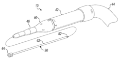
도 1은 본 개시의 실시예에 따른 수술용 버를 통합하며 환자에게 사용중인 수술용 절개 절단기 어셈블리의 투시 환경 뷰이다.
도 2는 도 1의 수술용 절개 절단기 어셈블리의 투시도이다.
도 3은 수술용 버의 상세한 정면 투시도이다.
도 4는 도 3의 수술용 버의 정면 상세도이다.
도 5는 도 3의 수술용 버의 측면도이다.
도 6은 수술용 버의 상세한 정면 투시도이다.
도 7은 도 6의 수술용 버의 정면 상세도이다.
도 8은 도 6의 수술용 버의 측면도이다.
도 9a는 제1 위치에서 사용 중인 도 3의 수술용 버의 상세한 환경 뷰이다.
도 9b는 제2 위치에서 사용 중인 도 3의 수술용 버의 상세한 환경 뷰이다.
대응하는 참조 번호들은 도면들의 여러 뷰들 전체에 걸쳐 대응하는 부분들을 나타낸다. The drawings described herein are for illustrative purposes only and not for all possible implementations, and are not intended to limit the scope of the present disclosure.
BRIEF DESCRIPTION OF THE DRAWINGS Figure 1 is a perspective environment view of a surgical incision cutter assembly incorporating a surgical bur according to an embodiment of the present disclosure and in use for a patient.
Figure 2 is a perspective view of the surgical incision cutter assembly of Figure 1;
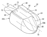
Figure 3 is a detailed front perspective view of the surgical bur.
Fig. 4 is a detailed front view of the surgical bur in Fig. 3;
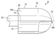
Figure 5 is a side view of the surgical burr of Figure 3;
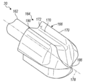
6 is a detailed frontal perspective view of the surgical bur.
Fig. 7 is a detailed front view of the surgical burr of Fig. 6;
8 is a side view of the surgical burr of Fig.
Figure 9a is a detailed environmental view of the surgical burr of Figure 3 in use in the first position.
Figure 9b is a detailed environmental view of the surgical burr of Figure 3 in use in the second position.
Corresponding reference numerals designate corresponding parts throughout the various views of the drawings.
다음의 설명은 회전 가능한 수술용 버들(또한 이하에서 수술용 버들로서 불리우는)의 개시를 포함한다. 이하에서 개시되는 바와 같이, 절단 에지들 및 트레일링 에지들. 미네소타주, 미니애폴리스에 사업장을 갖는, Medtronic, Inc.에 의해 판매된 Midas Rex® 수술용 바들과 같은, 수술용 바들은, 볼, 원통형, 타원형, 또는 다른 일반적으로 알려진 형태와 같은 복수의 외부 기하학적 구조들 중 하나 이상을 포함할 수 있다. 여기에서 개시된 것들을 포함한, 수술용 버들은 척추, 신경학, 및 이비인후과(ENT) 시술들을 포함한, 광범위한 수술들에 대해 적절할 수 있는 Midas Rex® Legend EHS 스타일러스 고속 수술용 드릴과 같은, 고속 드릴들에 의해 구동될 수 있다. 드릴들은 약 7,000 내지 70,000 rpm들을 포함하여, 분당 약 200 내지 75,000 회전(rpm)과 같은, 적절하고 선택 가능한 속도들에서 버들을 구동시킬 수 있다.The following description includes the disclosure of rotatable surgical burrows (also referred to hereinafter as surgical burrows). Cutting edges and trailing edges, as described below. Surgical bars, such as the Midas Rex® surgical bars sold by Medtronic, Inc., which have a business in Minneapolis, Minnesota, can have a plurality of external geometries, such as balls, cylinders, ellipses, Or < / RTI > The surgical burrs, including those disclosed herein, are driven by high speed drills, such as the Midas Rex® Legend EHS stylus high-speed surgical drill, which may be appropriate for a wide range of surgeries, including spinal, neurological, and ENT procedures. . Drills can drive the burrs at appropriate and selectable rates, such as about 200 to 75,000 revolutions per minute (rpm), including about 7,000 to 70,000 rpm.
예시적인 실시예들이 이제 수반되는 도면들을 참조하여 보다 완전하게 설명될 것이다. 다음의 설명은 사실상 단지 대표적이며 본 개시, 적용, 또는 사용들을 제한하도록 의도되지 않는다. 예를 들면, 인간 환자는 대상으로서 예시되지만, 대상은 임의의 적절한 대상일 수 있다는 것이 이해된다. 뿐만 아니라, 대상은 무생물이며 살아있지 않은 대상들을 포함할 수 있다. 살아있지 않은 대상들은 나무, 세라믹들, 금속 등으로 형성된 대상체들(objects)과 같은 고체 작업 재료들을 포함할 수 있다. 뼈 조직과 같은, 특정한 조직들은 단단할 수 있으며 절단 툴을 갖고 성형될 수 있다. 도면들 전체에 걸쳐, 대응하는 참조 번호들은 유사한 또는 대응하는 부분들 및 특징들을 나타낸다는 것이 이해되어야 한다.BRIEF DESCRIPTION OF THE DRAWINGS Exemplary embodiments will now be more fully described with reference to the accompanying drawings. The following description is merely exemplary in nature and is not intended to limit the present disclosure, application, or uses. For example, although a human patient is illustrated as a subject, it is understood that the subject can be any suitable subject. In addition, objects can be inanimate and include objects that are not alive. Non-living objects may include solid working materials such as objects formed of wood, ceramics, metals, and the like. Certain tissues, such as bone tissue, can be rigid and can be shaped with a cutting tool. It is to be understood that throughout the drawings, corresponding reference numerals denote similar or corresponding parts and features.
도 1은 수술용 접근 부위(32)에서 환자(30)에게 사용 중인 절개 툴(20)을 통합한 수술용 절개 절단기 어셈블리(10)를 도시한다. 환자(30)는 신경학적 수술을 받고 있는 것으로 예시된다. 환자(30)의 뇌 또는 다른 신경학적 구조들로의 접근은 종종 뼈(예로서, 두개골) 및 다른 조직들의 섬세한 절개를 요구한다. 도 1은 단지 예시적인 목적들만을 위해 제공되며; 여기에서 개시된 수술용 버들은 상이한 툴들 및/또는 절단기 어셈블리들에서 사용될 수 있으며 다른 시술들 및/또는 수술들을 위해 사용될 수 있다. 절개 절단기 어셈블리(10)는 절개 툴 드라이버(40)를 포함하며, 이것은 수술 접근 부위(32)에서 환자(30)의 뼈 및 인접한 조직의 일 부분을 절개하기 위해 이용되고 있다. 툴 드라이버는 상기 주지된 바와 같이, Midas Rex® Legend EHS 스타일러스 고속 수술용 드릴, 또는 다른 적절한 드라이버를 포함할 수 있다.Figure 1 illustrates a surgical
도 2는 수술용 절개 절단기 어셈블리(10)의 투시도이다. 절개 툴 드라이버(40)는 커넥터(44)에 연결된 모터 하우징(42)을 포함하며, 상기 커넥터는 호스 또는 케이블 어셈블리를 포함할 수 있다. 커넥터(44)는 모터 하우징(42) 내에 포함된 모터에 대한 외부 전력 및 제어를 공급한다. 절개 툴 드라이버(40)는 절개 툴(20)에 연결하는 부착 하우징(46)을 추가로 포함한다. 절개 툴 원위 단부는 수술용 버(64)를 포함한다. 절개 툴 근위 단부는 드라이버 연결(54)을 포함할 수 있다. 드라이버 연결(54)은 모터 하우징(42) 내에서 모터로부터 회전력을 수신하기 위해 부착 하우징(46) 내에서의 연결에 맞물릴 수 있다. 2 is a perspective view of a surgical
다음의 설명된 절개 툴들, 예를 들면, 수술용 버들은 특정한 수의 플루트들, 플루트당 경사면들, 플루트당 경사각들, 플루트당 여유면들, 랜드들, 축방향 부조면들, 여유면들 등을 가진 것으로서 도면들에 개시되고 설명되지만, 수술용 버들은 다른 양들의 이들 아이템들의 각각을 가질 수 있다.The following described dissection tools, e.g., surgical burrs, may be used to provide a specific number of flutes, inclinations per flute, inclinations per flute, per flight flutes, lands, axial apical surfaces, The surgical burr may have each of these items in different quantities.
도 3은 절개 툴(20)의 측면 및 투시도를 도시한다. 절개 툴(20)은 도 1의 절개 어셈블리(10)의 부분으로서 사용될 수 있다. 절개 툴(20)은 샤프트(62) 및 수술용 버(64)를 포함한다. 수술용 버(64)는 일반적으로 "매치 헤드(match head)", "신경" 또는 "성냥개비" 설계로서 불리울 수 있으며 설계를 가지며 몸체(66)를 포함한다. 몸체(66) 는 두 개의 볼록 랜드들(68) 및 두 개의 플루트들(70)을 갖는다. 플루트들(70)의 각각은 랜드들(68) 사이에 위치되며 대응하는 칩 공간(72)을 갖는다. 랜드들(68)은 볼록-형 및/또는 둥근형이며 절개 툴(20), 샤프트(62), 및/또는 수술용 버(64)의 세로 축(78)에 대해 각각의 180°위치들에 있을 수 있다. 수술용 버(64)는 세로 축(78) 주위에서 회전된다. 플루트들(70)은 또한 세로 축(78)에 대해 각각의 180°위치들에 있을 수 있다. 플루트들(70)의 각각은 절단 에지(76) 상에서 또는 그곳에서 하나 이상의 경사면들을 갖는다. 편평하거나 또는 오목한 표면일 수 있는 여유면(73)은 또한 절단 에지(76)에 대응할 수 있다. 여유면들(73)은 플루트들(70)에 대해 형성되며, 각각의 버 근위 단부(64a) 및 버 원위 단부(64b) 가까이에서, 플루트들(70)의 근위 및 원위 부분들 양쪽 모두 상에 있을 수 있다.Figure 3 shows a side view and perspective view of the
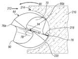
도 4 및 도 5를 추가로 참조하면, 수술용 버(64)는 절단 에지(76)를 추가로 포함한다. 절단 에지(76a)는 버(64)의 중심 또는 중심축(78)으로부터 거리(82)만큼 이격된다. 일반적으로, 절단 에지(76)는 중심축(78)으로부터 축방향으로 연장되며 그로부터 거리(82)만큼 이격된다. 뿐만 아니라, 절단 에지(76)는 일반적으로 플루트(70)의 에지 상에 놓여진다. 절단 에지(76)는 버(64)를 절단하는 동안 중심 포인트 또는 축(78) 주위를 화살표(80)의 방향으로 회전하는 리딩 에지이다. 거리(82)가 오프셋된 절단 에지(76)는 일반적으로 버(64)의 중심 포인트(78)로부터 최대 거리에서 절단 에지(76)를 위치시킨다. 즉 절단 에지(76)는 일반적으로, 여기에서 추가로 논의되는 바와 같이, 절단 에지(76)가 재료를 절단함에 따라 중심(78)으로부터 최대 외부 포인트 또는 거리에 있다. 리그(rig) 표면(84)은 버 원위 단부(64b)에서 절단 에지로부터 원위 팁(86)을 향해 연장되며, 그것을 통해 중심축(78)이 연장될 수 있다. 원위 팁(86)은 절개 툴(20)의 말단 원위 팁일 수 있다.4 and 5, the
버(64)의 트레일링 에지(90)는 곡선 랜드(68)의 에지에서 및 일반적으로 버(64)의 플루트(70)에 인접하여 형성될 수 있다. 트레일링 에지(90)는 일반적으로 버(64)가 화살표(80)의 방향으로 회전함에 따라 절단 에지(76)를 따르는 곡선 랜드(68)의 에지이다. 트레일링 에지(90)는 중심축(78)으로부터의 거리(94)에 있을 수 있다. 중심축(78)으로부터 절단 에지(76)의 거리(82) 및 중심축(78)으로부터 트레일링 에지(90)의 거리(94)는 대체로 같거나 또는 동일할 수 있다. 계속해서 도 4를 참조하면, 리딩 에지(76) 및 트레일링 에지(90)는 일반적으로 중심(78)으로부터의 거리들(82 및 94)과 대체로 같거나 또는 그것에 의해 정의되는 반경을 가진 원(96) 상에 있을 수 있다. 따라서, 절단 에지(76)는 원(96) 또는 트레일링 에지(90)를 지나 연장되지 않을 것이다. 절단 에지(76) 및 트레일링 에지(90) 양쪽 모두는 단지 원(96)으로 연장될 수 있다. 게다가, 절단 에지 및 트레일링 에지는, 여기에서 논의된 바와 같이, 각각의 하나 이상을 포함할 수 있다. 볼록 랜드(68)를 형성하는 표면의 제3 거리(95)는 제1 거리(82) 또는 제2 거리(94) 중 어느 하나보다 작을 수 있다. 뿐만 아니라, 여기에서 논의된 바와 같이, 플루트들의 여유 영역(73)은 제1, 제2 또는 제3 거리보다 작은 중심(78)으로부터의 제4 거리(73a)를 가질 수 있다. The trailing
도 4에서 추가로 예시되는 바와 같이, 두 개의 플루트들은 수술용 버(64)와 함께 포함될 수 있다. 제2 플루트(70a)는 제2 리딩 또는 절단 에지(76a) 및 제2 트레일링 에지(90a)를 포함할 수 있다. 따라서, 버(64)는 동등한 두 개의 절단 에지들(76, 76a) 및 두 개의 트레일링 에지들(90, 90a)을 가진 두 개의 플루트들(70, 70a)을 포함할 수 있다. 제2 절단 에지(76a) 및 제2 트레일링 에지(90a)는 또한 버(64)의 중심축(78) 상에 중심을 둔 원(96) 상에 형성될 수 있다.As further illustrated in FIG. 4, two flutes may be included with the
버(64)는 선택된 구조의 절개를 형성하기 위해 임의의 선택된 기하학적 구조를 포함할 수 있다. 예를 들면, 플루트는 약 5도(°) 내지 약 35°인 호(97)를 정의할 수 있다. 곡선 랜드(68)는 또한 호(99)를 정의할 수 있으며, 이것은 또한 약 175° 내지 약 145°인 트레일링 에지(90, 90a)로부터 절단 에지(76, 76a)까지의 아치형 거리일 수 있다. 호들(97, 99)은, 그러나, 임의의 선택된 아치형 각이도록 버(64)를 갖고 형성될 수 있다. 절단 에지들(76, 76a) 및 트레일링 에지(90, 90a)의 거리들(82, 94)은, 그러나, 모두 일반적으로 같을 수 있다.The
도 6 내지 도 8에 대한 참조로 가면, 수술용 버(164)가 예시된다. 수술용 버(164)는 상기 논의된 바와 같이, 수술용 버(64)와 유사한 방식으로 어셈블리(10)에서 절개 툴(20)로서 사용될 수 있다. 수술용 버(164)는 또한, 상기 논의된 바와 같이, 수술용 버(64)와 유사한 다양한 특징들 및 부분들을 포함할 수 있다. 따라서, 이러한 부분은 상당히 상세하게 설명되지 않을 것이며 100까지 증가된 상기 주지된 것들과 유사한 참조 번호들을 가질 것이다.6 to 8, a
수술용 버(164)는 수술용 버(164)의 샤프트(162)를 통해 연장되는 중심축(178)을 포함할 수 있다. 수술용 버(164)는 몸체(166)를 포함한다. 수술용 버(164)는 절단 에지(176)를 가진 플루트(170)를 포함할 수 있다. 뿐만 아니라, 트레일링 에지(190)는 몸체(166) 상에 형성될 수 있으며 수술용 버(164)가 화살표(180)의 방향으로 회전함에 따라 절단 에지(176)를 따를 수 있다. 뿐만 아니라, 칩 수집 영역(172)이 플루트(170)에 정의될 수 있다. 볼록 랜드(168)는 절단 에지(176) 및 트레일링 에지(190) 사이에 형성된다.The
수술용 버(164)는 수술용 버(164)가 3개의 절단 에지들(176, 176a 및 176b)을 포함한다는 점에서 수술용 버(64)와 상이할 수 있다. 따라서, 수술용 버(164)는 또한 3개의 플루트들(170, 170a 및 170b)을 포함할 수 있다. 뿐만 아니라, 수술용 버는 3개의 트레일링 에지들(190, 190a 및 190b)을 포함할 수 있다.The
수술용 버(64)와 유사하게, 수술용 버(164)는 수술용 버(164)의 외부 둘레 또는 에지를 정의하는 원(196)을 정의하거나 또는 가질 수 있다. 따라서, 절단 에지(176)는 중심축(178)으로부터의 거리(182)에 형성될 수 있다. 트레일링 에지(190)는 중심축(178)으로부터의 거리(194)에 형성될 수 있다. 거리(182)는 거리(194)와 실질적으로 동일하거나 또는 같을 수 있다. 그러므로, 절단 에지(176) 및 트레일링 에지(190)는 양쪽 모두 원(196) 상에 배치될 수 있다. 부가적으로, 수술용 버는 일반적으로 축(178) 상에 있는 원위 팁(186) 및 수술용 버(164)와 유사한 다른 피처들을 포함할 수 있다. 또한, 볼록 랜드(168)는 제1 거리(182) 또는 제2 거리(194) 중 어느 하나보다 작은 중심축(178)으로부터의 제3 거리(195)인 표면을 가질 수 있다.Similar to the
수술용 버(164)는, 그러므로, 3개의 플루트들(170, 170a, 170b)을 포함하는 반면 수술용 버(64)는 2개의 플루트들을 포함한다. 버(164) 상에서, 플루트들(170, 170a, 170b)의 아치형 거리 및 트레일링 에지로부터 다음 절단 에지(176, 176a, 176b)까지의 아치형 거리는 임의의 적절한 거리이도록 선택될 수 있다. 다양한 부분들 사이에서의 아치형 거리들은 버(164) 상에 보다 많은 수의 플루트들이 있음을 고려하면 버(64) 상에서보다 작을 수 있다. The
다양한 실시예들에 따른, 수술용 버는 임의의 적절한 수의 플루트들을 포함할 수 있다는 것이 추가로 이해된다. 어찌됐든, 절단 에지 및 트레일링 에지 양쪽 모두는 일반적으로 수술용 버의 외부 범위를 정의하는 원 상에 있을 수 있다. 그러므로, 중심축으로부터 절단 에지 및 트레일링 에지까지의 거리는 일반적으로, 상기 논의된 바와 같이, 실질적으로 같거나 또는 동일할 수 있다. 뿐만 아니라, 수술용 버는 볼 형태, 원통형 형태, 또는 다른 적절한 형태를 포함하는 것과 같은 임의의 적절한 형태로 형성될 수 있다는 것이 이해된다. 다양한 실시예들에 따른, 수술용 버는, 그러므로, 도 1에 예시되고 여기에서 추가로 논의되는 바와 같이 환자(30)와 같은, 대상의 적절한 부분의 절개 또는 절제를 형성하기 위해 사용될 수 있다.It is further understood that the surgical burr, according to various embodiments, may include any suitable number of flutes. In any event, both the cutting edge and the trailing edge may be in a circle that generally defines the outer extent of the surgical bur. Therefore, the distance from the central axis to the cutting edge and the trailing edge may be substantially the same or substantially the same, as discussed above. In addition, it is understood that the surgical bur can be formed in any suitable form such as a ball shape, a cylindrical shape, or any other suitable shape. In accordance with various embodiments, a surgical burr can therefore be used to form an incision or ablation of a suitable portion of the subject, such as the
도 9a 및 도 9b에 대한 참조로 가면, 수술용 버(64)는 뼈 구조 또는 질량(210)에 대하여 예시된다. 수술용 버(64)는, 상기 논의된 바와 같이, 절단 에지(76) 및 절단 에지(76a)를 포함한다. 수술용 버(64)는 일반적으로 절개 툴(20)의 축(78)을 따라 축방향으로 이동하거나 또는 구멍을 뚫을 수 있다. 따라서, 도 9a 및 도 9b에서 예시된 바와 같이, 수술용 버(64)는 축(78)을 따라 및 일반적으로 페이지의 평면 밖으로 바로 이동할 수 있다. 수술용 버(64)의 부가적인 움직임은, 화살표(212)의 방향으로와 같은, 방사상 또는 일반적으로 중심축(78)으로부터 멀리 절단될 수 있다. 수술용 버가 화살표(212)의 방향으로 골 질량(210)으로 이동됨에 따라, 채널 또는 트로프(trough)(214)가 형성될 수 있다. 채널(214)을 형성할 때, 절단 에지(76)는 골 질량(210)으로부터 하나 이상의 뼈 칩들(218)을 형성할 수 있다. 뼈 칩들(218)은 수술용 버(64)의 플루트(70)로 이동될 수 있다. 수술용 버(64)의 플루트(70)로 이동할 때, 뼈 칩(218)은, 일반적으로 화살표(212)의 방향인, 수술용 버(64)의 절단 경로 밖으로 이동될 수 있다. Referring to Figs. 9A and 9B, the
뼈(210)를 절단할 때, 수술용 버(64)는, 상기 논의된 바와 같이, 화살표(80)의 방향으로 회전하고 있다. 뿐만 아니라, 버(64)는 뼈(210)에 채널(214)을 형성하기 위해 화살표(212)의 방향으로 이동된다. 그러므로, 화살표(80)의 방향으로 이동하는, 절단 에지(76)는, 뼈 칩(218)을 절단하며 그 후 계속해서 화살표(80)의 방향으로 및 일반적으로 채널(214)의 정면 벽 또는 절단 영역(220)으로부터 떨어져 회전한다. 뼈 칩(218)을 형성할 때 절단 에지(76)는, 그러므로, 채널(214)의 이미 형성된 부분을 향해 뼈 칩(218)을 이동시킨다.When cutting
도 9b에 예시된 바와 같이, 뼈 칩(218)을 형성한 후, 절단 에지(76)는 채널의 형성 부분으로 또는 그것을 통해 지나가며 트레일링 에지(90)는 절단 에지(76)가 정면에 맞물리거나 또는 채널(214)의 벽(220)을 형성함에 따라 트레일링한다. 상기 논의된 바와 같이, 트레일링 에지(90)는 중심축(78)으로부터 절단 에지(76)의 거리(82)와 실질적으로 같거나 또는 동일한 중심축(78)으로부터의 거리(94)를 포함할 수 있다. 그러므로, 트레일링 에지(90)는 절단 에지(76) 및 곧 있을 제2 절단 에지(76a)와 중심축(78)으로부터 대체로 동일한 거리에서 벽(220)에 맞물릴 수 있다. 이것은 여기에서 추가로 논의되는 바와 같이, 절단 에지(76a)를 갖고 절단하는 동안 버(64)를 유도하며 및/또는 안정화시킨다. 9B, after forming the bone chips 218, the
절단 에지(76a)는 중심축(78)으로부터의 거리(82)와 대체로 동일한 거리(82a)를 포함한다. 그러므로, 절단 에지(76a)는, 벽(220)을 절단하기 전에, 일반적으로 트레일링 에지(90)와 대체로 동일한 위치에 있다. 중심축(78)으로부터 벽(220)까지의 반경 또는 거리가 트레일링 에지(90) 및 제2 절단 에지(76a)에 대해 대체로 동일하기 때문에, 제2 절단 에지(76a)가 뼈 칩(218)의 절단 또는 형성을 개시하기 전에 버(64)의 점프 또는 저킹(jerking)은 없다. 그러므로, 트레일링 에지(90)는 제2 절단 에지(76a)가 벽(220)을 절단하기 전에 채널(214)의 벽(220)에 대하여 안정화 에지 또는 표면을 형성하거나 또는 그로서 동작할 수 있다. 유사하게, 제2 트레일링 에지(90a)는 절단 에지(76)가 채널(214)의 전방향 벽(220)을 절단하기 전에 절단 에지(76)에 대하여 안정화 표면 또는 에지로서 동작할 수 있다.The
버(64)는 일반적으로, 약 700 내지 약 75,000 rpm과 같은, 선택된 회전율로 모터에 의해 회전할 수 있다. 예로서, 버(64)는 약 7,000 rpm으로 회전할 수 있다. 그러므로, 전방향 벽(220) 상에서 절단 에지들(76 및 76a)의 맞물림 및 트레일링 에지 서비스들(90, 90a)에 의한 안정화는 버(64)가 채널(214)을 형성할 때 버(64)를 대체로 안정화시킬 수 있다.The
도 9a에 대한 참조로 돌아가면, 버(64)는 방사상 절단 동안, 예를 들면, 절단 에지(76)가 뼈(210)를 절단하거나 또는 절개하기 위해 뼈 칩(218)을 형성할 때 안정화된다. 버(64)는 방사상 절단 동안 감소된 진동 및 힘들 및 채터를 경험할 수 있다. 일 예에서, 버(64)는 약 42%를 포함한, 약 20 내지 40%의 감소를 포함하여, 적어도 약 40%만큼 진동의 감소를 경험할 수 있다. 진동력들은 가속도계를 갖고 측정되며 m/s2와 같은 단위들을 사용하여 지-포스들(g-forces)로 보고될 수 있다. 9A, the
수술 동안, 안정화는 채널 내에서 회전하는 버(64)에 의해 발생할 수 있고, 절단 에지(76)는 채널(214)의 정면 벽(220)으로부터 멀리 이동한다. 절단 에지(76)가 정면 벽(220)으로부터 멀리 이동함에 따라, 트레일링 에지(90)는 다음 절단 에지(76a) 전에 벽(220)에 맞물릴 수 있다. 버(64)의 회전 속도로 인해, 벽(220)을 떠나는 절단 에지 및 벽에 맞물리는 트레일링 에지(90) 사이에서의 경과 시간은, 약 마이크로초들과 같이, 매우 짧을 수 있다.During surgery, stabilization may occur by rotating
트레일링 에지(90)는, 그러나, 제2 절단 에지(76a)가 정면 벽의 절단 및 뼈 칩(218)의 형성을 시작하기 전에 벽(220)에 맞물린다. 그러므로, 절단 에지(76a)가 채널(214)의 정면 벽(220)을 절단하기 시작함에 따라, 버(64)는 정면 벽(220)에 대하여 대체로 안정화될 수 있다. 이것은 적어도 트레일링 에지(90)가 절단 에지(76a)와 중심(78)으로부터 동일하거나 또는 대체로 동일한 거리이기 때문이다. The trailing
뿐만 아니라, 트레일링 에지(90)는 버(64)가 화살표(80)의 방향으로 회전하며 절단 에지(76a)가 벽(220)을 따라 뼈 칩들을 절단하고 형성함에 따라 버(64)를 안정화시키기 위해 벽(220)을 따라 계속해서 라이딩할 수 있다. 그러므로, 트레일링 에지는 버(64)를 안정화시키는 가이드로서 동작할 수 있다. 트레일링 에지(90)는 다음의 절단 에지, 예를 들면 절단 에지(76a)가 도 9b에 예시된 바와 같이 트레일링 에지(90)를 따름에 따라 버(64)를 안정화시킨다. 이것은 채널(214)을 절단하는 동안 버(64)의 안정을 돕는다.The trailing
절단 에지(76)와 실질적으로 동시에 또는 직전에 정면 벽과 트레일링 에지(90)의 접촉은 절단하거나 또는 절개하는 동안 버(64)의 채터 또는 진동을 감소시킬 수 있다. 이것은 버(64)를 포함한 어셈블리(10)의 사용 동안 사용자 피로를 감소시킬 수 있다. 이것은 또한 감소된 진동 및 채터로 인해 버(64)를 사용할 때 절개의 정밀도를 증가시킬 수 있다. 따라서, 사용자는 시술을 위해 요구된 시간을 감소시키고 절단의 정밀도를 증가시키기 위해 중단 없이 더 길게 절단할 수 있을 것이다. 따라서, 버(64)는 또한 마이크-컷(mic-cut)의 기회를 감소시킬 수 있다. 상기 논의된 바와 같이, 트레일링 에지 및 절단 에지는 에지들의 임의의 적절한 조합일 수 있으며 구체적으로 상기 참조 번호에 의해 참조된 것들일 필요는 없다는 것이 추가로 이해된다.Contacting the front wall with the trailing
채널(214)을 절단할 때, 다양한 수술 절차들이 발생할 수 있다. 예를 들면, 버 홀이 도 1에 예시된 바와 같이, 두피에 형성될 수 있다. 버 홀은 뇌심부 시뮬레이션 프로브의 배치, 종양의 절제 등과 같은, 다양한 절차들을 위해 뇌 경막 및 뇌 조직으로의 접근을 허용하기 위해 사용될 수 있다. 뿐만 아니라, 다른 절차들은 다른 두개골 조직들에 홀을 형성하는 것, 긴 뼈들 및 척추골을 포함한, 조직 및 다른 뼈 물질의 함몰 또는 제거를 형성하는 것, 및 다른 적절한 절차들을 포함할 수 있다. 특정 절차에 관계없이, 그러나, 버(64)는 절단 에지(76a)와 중심축(78)에 대해 대체로 동일한 방사 위치에서 트레일링 에지(90)의 위치 결정으로 인해 상당한 진동 없이 채널(214) 및 뼈(210)를 절단할 수 있다.When cutting
예시적인 실시예들이, 본 개시가 철저할 것이며, 이 기술분야에서 숙련된 자들에게 범위를 완전하게 전달하도록 제공된다. 특정 구성요소들, 디바이스들, 및 방법들의 예들과 같은, 다수의 특정 세부사항들이, 본 개시의 실시예들의 철저한 이해를 제공하기 위해 제시된다. 특정 세부사항들이 이용될 필요는 없고, 예시적인 실시예들이 많은 상이한 형태들로 구체화될 수 있으며 본 개시의 범위를 제한하도록 해석되지 않아야 한다는 것이 이 기술분야의 숙련자들에게 명백할 것이다. 몇몇 예시적인 실시예들에서, 잘 알려진 프로세스들, 잘 알려진 디바이스 구조들, 및 잘 알려진 기술들은 상세히 설명되지 않는다. 게다가, 수술용 버의 설계 및 구조는 상기 제공된 특정 예들로부터 변경될 수 있지만, 바로 이어지는 절단 에지와 같은, 다음과 같거나 또는 대체로 같은 중심으로부터의 거리를 갖는 트레일링 에지를 포함한다. 이것은 뼈 조직을 포함한, 조직의 실질적으로 부드러우며 지터 또는 점프가 없는 절개를 허용할 수 있다. Exemplary embodiments are provided so that this disclosure will be thorough and complete, and will fully convey the scope to those skilled in the art. Many specific details are set forth in order to provide a thorough understanding of embodiments of the present disclosure, such as examples of specific components, devices, and methods. It will be apparent to those skilled in the art that the specific details need not be utilized and that the illustrative embodiments may be embodied in many different forms and should not be construed as limiting the scope of the disclosure. In some exemplary embodiments, well-known processes, well-known device structures, and well-known techniques are not described in detail. In addition, the design and construction of the surgical bur includes trailing edges that may vary from the specific examples provided above, but have distances from the following or substantially the same center, such as immediately following cutting edge. This may allow a substantially smooth, jitter- or jumping-free incision of the tissue, including bone tissue.
여기에서 사용된 전문 용어는 단지 특정한 예시적인 실시예들을 설명할 목적을 위한 것이며 제한적이도록 의도되지 않는다. 여기에서 사용된 바와 같이, 단수형 형태들("a", "an", 및 "the")은, 맥락이 달리 명확하게 표시되지 않는다면, 또한 복수형 형태들을 포함하도록 의도될 수 있다.The terminology used herein is for the purpose of describing particular illustrative embodiments only and is not intended to be limiting. As used herein, singular forms ("a", "an", and "the") may also be intended to include plural forms unless the context clearly dictates otherwise.
실시예들의 앞서 말한 설명은 예시 및 설명의 목적들을 위해 제공되었다. 그것은 철저하거나 또는 개시를 제한하도록 의도되지 않는다. 특정한 실시예의 개개의 요소들 또는 특징들은 일반적으로 상기 특정한 실시예에 제한되지 않으며, 적용 가능한 경우, 구체적으로 도시되거나 또는 설명되지 않을지라도, 상호 교환 가능하며 선택된 실시예에서 사용될 수 있다. 그것은 또한 많은 방식들로 변경될 수 있다. 이러한 변화들은 본 개시로부터의 일탈로서 간주되지 않으며, 모든 이러한 수정들은 본 개시의 범위 내에 포함되도록 의도된다.The foregoing description of the embodiments has been presented for purposes of illustration and description. It is not intended to be exhaustive or to limit the disclosure. The individual elements or features of a particular embodiment are not generally limited to the specific embodiments described above and, if applicable, may be used interchangeably and in selected embodiments, even if not specifically shown or described. It can also be changed in many ways. Such variations are not to be regarded as a departure from this disclosure, and all such modifications are intended to be included within the scope of this disclosure.
Claims (20)
근위 단부로부터 원위 단부를 향해 연장된 가늘고 긴 샤프트;
상기 가늘고 긴 샤프트의 상기 원위 단부에서의 수술용 버(surgical bur)로서:
제1 플루트(flute),
제1 절단 에지, 및
제1 트레일링 에지를 포함하며,
상기 제1 절단 에지는 조직을 절단하도록 구성되며 상기 수술용 버의 중심축으로부터 제1 거리가 이격되고,
상기 제1 트레일링 에지는 상기 수술용 버의 상기 중심축으로부터 상기 제1 거리가 이격되는, 상기 수술용 버를 포함하며,
상기 수술용 버는 상기 중심축에 대하여 방사 방향으로 조직을 절개하도록 구성되는, 수술용 절개 어셈블리.A surgical incision assembly comprising:
An elongated shaft extending from the proximal end toward the distal end;
A surgical bur at said distal end of said elongate shaft,
The first flute,
A first cutting edge, and
A first trailing edge,
Wherein the first cutting edge is configured to cut tissue and is spaced a first distance from a central axis of the surgical bur,
Wherein the first trailing edge comprises the surgical bur, wherein the first distance from the central axis of the surgical bur is spaced apart,
Wherein the surgical bur is configured to incise tissue radially with respect to the central axis.
상기 중심축을 따라 상기 조직으로 축 방향으로 절개하도록 구성된 버 원위 팁을 더 포함하는, 수술용 절개 어셈블리.The method according to claim 1,
Further comprising a vertebral distal tip configured to axially incision into the tissue along the central axis.
상기 수술용 버는 상기 제1 트레일링 에지로부터 연장된 벽에 의해 형성된 볼록 랜드(convex land)를 더 포함하며, 상기 볼록 랜드는 상기 중심축으로부터 제2 거리이며 상기 제2 거리는 상기 제1 거리보다 작은, 수술용 절개 어셈블리.The method according to claim 1 or 2,
Wherein the surgical bur includes a convex land formed by a wall extending from the first trailing edge, wherein the convex land is a second distance from the central axis and the second distance is less than the first distance , Surgical incision assembly.
상기 수술용 버는 제2 절단 에지 및 제2 트레일링 에지를 가진 제2 플루트를 더 포함하며;
상기 볼록 랜드는 일반적으로 상기 제1 절단 에지 및 상기 제2 트레일링 에지 사이에서 상기 중심축 주위에서의 호 상에서 연장되는, 수술용 절개 어셈블리.The method of claim 3,
The surgical bur includes a second flute having a second cutting edge and a second trailing edge;
Wherein the convex land generally extends over the arc between the first cutting edge and the second trailing edge about the central axis.
상기 제1 플루트는 복수의 플루트를 포함하며, 상기 복수의 플루트의 각각의 플루트는 절단 에지 및 트레일링 에지를 포함하는, 수술용 절개 어셈블리.The method according to any one of claims 1 to 3,
Wherein the first flute comprises a plurality of flutes, each flute of the plurality of flutes comprising a cutting edge and a trailing edge.
상기 제1 플루트는 칩 클리어링 영역(chip clearing area)을 포함하는, 수술용 절개 어셈블리.The method according to any one of claims 1 to 5,
Wherein the first flute comprises a chip clearing area.
상기 제1 절단 에지 및 상기 제1 트레일링 에지는 안정된 방사상 절단을 허용하도록 구성되는, 수술용 절개 어셈블리.The method according to any one of claims 1 to 6,
Wherein the first cutting edge and the first trailing edge are configured to allow stable radial cutting.
상기 샤프트의 상기 근위 단부에 모터 연결부를 더 포함하는, 수술용 절개 어셈블리.The method according to any one of claims 1 to 7,
Further comprising a motor connection at the proximal end of the shaft.
상기 조직의 절개를 위해 상기 수술용 버를 구동하기 위한 모터를 더 포함하는, 수술용 절개 어셈블리.The method according to any one of claims 1 to 8,
Further comprising a motor for driving the surgical bur for incision of the tissue.
근위 단부로부터 원위 단부를 향해 연장된 가늘고 긴 샤프트;
상기 가늘고 긴 샤프트의 상기 원위 단부에서의 수술용 버로서:
제1 절단 에지 및 제1 트레일링 에지를 가진 제1 플루트,
제2 절단 에지 및 제2 트레일링 에지를 가진 제2 플루트를 포함하며,
상기 제1 절단 에지 및 상기 제2 절단 에지는 조직을 절단하도록 구성되며 양쪽 모두가 상기 수술용 버의 중심축으로부터 제1 거리가 이격되고,
상기 제1 트레일링 에지 및 상기 제2 트레일링 에지는 상기 수술용 버의 상기 중심축으로부터 상기 제1 거리가 이격되는, 상기 수술용 버를 포함하며,
상기 수술용 버는 상기 중심축에 대하여 방사 방향으로 이동하면서 안정된 방식으로 조직을 절개하도록 구성되는, 수술용 절개 어셈블리.A surgical incision assembly comprising:
An elongated shaft extending from the proximal end toward the distal end;
A surgical bur at said distal end of said elongated shaft;
A first flute having a first cutting edge and a first trailing edge,
A second flute having a second cutting edge and a second trailing edge,
Wherein the first cutting edge and the second cutting edge are configured to cut tissue and both are spaced a first distance from a central axis of the surgical bur,
Wherein the first trailing edge and the second trailing edge are spaced apart from the central axis of the surgical bur by a first distance,
Wherein the surgical bur is configured to incise the tissue in a stable manner while moving radially relative to the central axis.
상기 수술용 버를 구동하도록 구성된 모터; 및
상기 모터를 하우징하며 상기 수술용 버를 이용해서 상기 조직을 절개하기 위해 사용자에 의해 조작되도록 구성된 모터 하우징을 더 포함하는, 수술용 절개 어셈블리.The method of claim 10,
A motor configured to drive the surgical burr; And
Further comprising a motor housing configured to house the motor and to be manipulated by a user to incise the tissue using the surgical bur.
상기 모터는 제1 회전 방향으로 상기 수술 버를 구동하도록 구성되며;
상기 제1 트레일링 에지는 상기 제2 절단 에지가 상기 조직을 절단하기 전에 절단될 상기 조직의 표면에 맞물리는, 수술용 절개 어셈블리.The method of claim 11,
The motor is configured to drive the surgical burr in a first rotational direction;
Wherein the first trailing edge engages a surface of the tissue to be cut before the second cutting edge cuts the tissue.
상기 샤프트의 상기 근위 단부는 상기 모터로부터 상기 샤프트로 회전력을 전달하기 위해 모터 맞물림 섹션을 포함하는, 수술용 절개 어셈블리.The method according to any one of claims 10 to 12,
Wherein the proximal end of the shaft includes a motor engaging section for transmitting rotational force from the motor to the shaft.
상기 플루트는 상기 제1 거리 또는 상기 제2 거리보다 작은 상기 중심축으로부터의 제3 거리를 갖는 플루트 표면을 포함하며;
상기 플루트는 칩 클리어링 영역을 형성하는, 수술용 절개 어셈블리.The method according to any one of claims 10 to 13,
The flute comprising a flute surface having a first distance or a third distance from the center axis that is less than the second distance;
Wherein the flutes form a chip clearing area.
상기 수술용 버는 일반적으로 상기 제1 절단 에지로부터 상기 제1 트레일링 에지까지 상기 중심축 주위에서의 제1 호 상에서 연장된 제1 볼록 랜드 및 일반적으로 상기 제2 절단 에지로부터 상기 제2 트레일링 에지까지 상기 중심축 주위에서의 제2 호 상에서 연장된 제2 볼록 랜드를 더 포함하는, 수술용 절개 어셈블리.The method according to any one of claims 10 to 14,
The surgical burr generally has a first convex land extending from the first cutting edge to the first trailing edge on the first call around the central axis and a second convex land extending generally from the second cutting edge to the second trailing edge, Further comprising a second convex land extending on the second call around the central axis.
상기 버의 중심축 주위에서 상기 버를 회전 구동하기 위해 모터에 동력을 공급하는 단계;
상기 중심축으로부터 방사 방향으로 상기 수술용 버를 이동시키는 단계; 및
상기 버의 절단 에지와 정면 벽을 맞물리기 전에 상기 버의 트레일링 에지와 채널의 상기 정면 벽을 맞물리는 단계를 포함하며,
상기 버는 상기 정면 벽을 부드럽게 절단하도록 구성되는, 재료를 제거하는 방법.As a method of removing material in a radial direction from a central axis of a burr in general,
Powering the motor to rotationally drive the burr around the central axis of the burr;
Moving the surgical burr radially from the central axis; And
And engaging the front wall of the channel with the trailing edge of the bur before engaging the cutting edge of the bur with the front wall,
Wherein the bur is configured to smoothly cut the front wall.
상기 정면 벽을 절단하고 상기 정면 벽으로부터 상기 재료를 제거함으로써 상기 재료에 채널을 형성하는 단계를 더 포함하는, 재료를 제거하는 방법.18. The method of claim 16,
Further comprising forming a channel in the material by cutting the front wall and removing the material from the front wall.
상기 중심축을 따라 상기 재료로 축 방향으로 상기 버를 이동시킴으로써 상기 재료로 보어를 형성하는 단계를 더 포함하는, 재료를 제거하는 방법.The method according to claim 16 or 17,
Further comprising forming the bore with the material by moving the burr axially in the material along the central axis.
상기 버를 이용해서 홀을 형성하는 단계를 더 포함하는, 재료를 제거하는 방법.The method according to any one of claims 16 to 18,
≪ / RTI > further comprising forming the hole using the burr.
상기 홀을 통해 상기 재료로 대상체(object)를 삽입하는 단계를 더 포함하는, 재료를 제거하는 방법.The method of claim 19,
And inserting an object through the hole into the material.
Applications Claiming Priority (3)
| Application Number | Priority Date | Filing Date | Title |
|---|---|---|---|
| US14/840,217 US10265082B2 (en) | 2015-08-31 | 2015-08-31 | Surgical burs |
| US14/840,217 | 2015-08-31 | ||
| PCT/US2016/049464 WO2017040509A1 (en) | 2015-08-31 | 2016-08-30 | Surgical burs |
Publications (1)
| Publication Number | Publication Date |
|---|---|
| KR20180048858A true KR20180048858A (en) | 2018-05-10 |
Family
ID=56889238
Family Applications (1)
| Application Number | Title | Priority Date | Filing Date |
|---|---|---|---|
| KR1020187008903A KR20180048858A (en) | 2015-08-31 | 2016-08-30 | Surgical burr |
Country Status (8)
| Country | Link |
|---|---|
| US (3) | US10265082B2 (en) |
| EP (1) | EP3344164B1 (en) |
| JP (1) | JP2018526175A (en) |
| KR (1) | KR20180048858A (en) |
| CN (1) | CN108135624B (en) |
| AU (1) | AU2016315693A1 (en) |
| CA (1) | CA2997094A1 (en) |
| WO (1) | WO2017040509A1 (en) |
Families Citing this family (6)
| Publication number | Priority date | Publication date | Assignee | Title |
|---|---|---|---|---|
| US9232952B2 (en) | 2012-04-16 | 2016-01-12 | Medtronic Ps Medical, Inc. | Surgical bur with non-paired flutes |
| US9883873B2 (en) | 2013-07-17 | 2018-02-06 | Medtronic Ps Medical, Inc. | Surgical burs with geometries having non-drifting and soft tissue protective characteristics |
| US10335166B2 (en) | 2014-04-16 | 2019-07-02 | Medtronics Ps Medical, Inc. | Surgical burs with decoupled rake surfaces and corresponding axial and radial rake angles |
| US9955981B2 (en) | 2015-03-31 | 2018-05-01 | Medtronic Xomed, Inc | Surgical burs with localized auxiliary flutes |
| US10265082B2 (en) * | 2015-08-31 | 2019-04-23 | Medtronic Ps Medical, Inc. | Surgical burs |
| US11000305B2 (en) | 2017-08-02 | 2021-05-11 | Stryker Corporation | Surgical tool systems, and methods of use thereof |
Family Cites Families (145)
| Publication number | Priority date | Publication date | Assignee | Title |
|---|---|---|---|---|
| US372400A (en) | 1887-11-01 | Dental burring-tool | ||
| US533573A (en) | 1895-02-05 | John d | ||
| US1309706A (en) | 1919-07-15 | Twist-drill | ||
| US180554A (en) | 1876-08-01 | Improvement in metal-drill bits | ||
| US533673A (en) | 1895-02-05 | Process of ornamenting surfaces | ||
| US662349A (en) | 1900-04-09 | 1900-11-20 | Henry Burton | Carbureter. |
| US2847895A (en) | 1950-06-26 | 1958-08-19 | Frederick T Huntington | Combination bullet press and ammunition reloader tool |
| US2795979A (en) | 1954-07-14 | 1957-06-18 | Gen Motors Corp | Chatterless countersink cutter |
| US2847885A (en) | 1956-08-02 | 1958-08-19 | Cleveland Twist Drill Co | Deep hole drill |
| US2903922A (en) | 1957-06-24 | 1959-09-15 | Cincinnati Milling Machine Co | Self-centering drill |
| US3387511A (en) | 1966-05-02 | 1968-06-11 | Lockheed Aircraft Corp | Twist drill |
| US3387554A (en) | 1967-12-04 | 1968-06-11 | Vincent W. Cherre | Pressurizer unit for coffee percolator |
| US3937222A (en) | 1973-11-09 | 1976-02-10 | Surgical Design Corporation | Surgical instrument employing cutter means |
| US3872594A (en) | 1974-01-21 | 1975-03-25 | Jerome M Gerteisen | Rotary burnishers |
| US4602900A (en) | 1979-10-01 | 1986-07-29 | Arpaio Jr Jerry | Micro drill with modified drill point |
| US4740121A (en) | 1979-10-18 | 1988-04-26 | Rockwell International Corporation | Reamer with unequally spaced flutes |
| US4445509A (en) | 1982-02-04 | 1984-05-01 | Auth David C | Method and apparatus for removal of enclosed abnormal deposits |
| DE3233968A1 (en) | 1982-09-14 | 1984-03-15 | Hartmetallwerkzeugfabrik Andreas Maier GmbH + Co KG, 7959 Schwendi | MULTIPLE LIP DRILL |
| US4699550A (en) | 1984-01-31 | 1987-10-13 | Baker John W | Cranial perforator |
| US4600006A (en) | 1984-01-31 | 1986-07-15 | Baker John W | Cranial perforator |
| US4951690A (en) | 1984-01-31 | 1990-08-28 | Baker John W | Method of drilling through a bone structure |
| CH671150A5 (en) | 1986-10-13 | 1989-08-15 | Jaquet Orthopedie | |
| US4803982A (en) | 1987-03-26 | 1989-02-14 | Baker John W | Cranial perforator |
| DE3890886T1 (en) | 1987-10-14 | 1990-06-07 | John W Baker | DRILL HEAD FOR SKULL DRILLS |
| US4830000A (en) | 1987-12-31 | 1989-05-16 | Aspen Laboratories, Inc. | Surgical drill |
| JP2603993B2 (en) | 1988-03-11 | 1997-04-23 | 俊明 細井 | Drill |
| US5011342A (en) | 1988-03-14 | 1991-04-30 | 501 Greenfield Industries, Inc. | Twist drill |
| US5122134A (en) | 1990-02-02 | 1992-06-16 | Pfizer Hospital Products Group, Inc. | Surgical reamer |
| KR940000112B1 (en) | 1990-07-05 | 1994-01-05 | 주식회사 대웅제약 | 3-substituted cephem compounds |
| US5658305A (en) | 1990-08-31 | 1997-08-19 | Baker; John W. | Surgical router bit |
| US5190548A (en) | 1991-04-10 | 1993-03-02 | Linvatec Corporation | Surgical reamer |
| FR2676639A1 (en) | 1991-05-21 | 1992-11-27 | Peltier Patrick | IMPROVEMENTS ON HELICAL FORESTS FOR BONE SURGERY, PARTICULARLY FOR DENTAL SURGERY. |
| US5143490A (en) | 1991-07-26 | 1992-09-01 | Roto Zip Tool Corporation | Bit for cutting sheetrock |
| US5146669A (en) | 1991-07-31 | 1992-09-15 | Fabiano Joseph F | Method of manufacturing an insert drill |
| US5209612A (en) | 1992-03-27 | 1993-05-11 | The Budd Company | Cutting tool |
| US5236291A (en) | 1992-08-31 | 1993-08-17 | General Motors Corporation | Multi-tooth drill with improved chisel edge |
| US5514141A (en) | 1992-11-18 | 1996-05-07 | Howmedica, Inc. | Small joint reamer |
| JP2723768B2 (en) | 1992-11-27 | 1998-03-09 | 本田技研工業株式会社 | Ball end mill |
| JPH07108409A (en) | 1993-05-19 | 1995-04-25 | Dijet Ind Co Ltd | Varnishing drill |
| US5810517A (en) | 1993-06-28 | 1998-09-22 | Monroe Cutting Tool Inc. | Rotary milling cutters |
| US5467837A (en) | 1993-09-01 | 1995-11-21 | Kennametal Inc. | Rotary drill bit having an insert with leading and trailing relief portions |
| US5562673A (en) | 1994-03-03 | 1996-10-08 | Howmedica Inc. | Awls for sizing bone canals |
| USD378780S (en) | 1994-03-07 | 1997-04-08 | Arthrex Inc. | Cannulated headed reamer |
| FR2720017B1 (en) | 1994-05-19 | 1996-08-09 | Europ Propulsion | Removable copy cutter. |
| SE504339C2 (en) | 1994-06-13 | 1997-01-13 | Sandvik Ab | drilling Tools |
| SE509383C2 (en) | 1994-06-13 | 1999-01-18 | Sandvik Ab | drilling Tools |
| US5579185A (en) | 1994-09-28 | 1996-11-26 | Industrial Technology Research Institute | Video tape recording/reproducing apparatus having automatic predict and mode changing capability |
| WO1996012453A1 (en) | 1994-10-24 | 1996-05-02 | Smith & Nephew Inc. | Hollow surgical cutter with apertured flutes |
| US5575650A (en) | 1995-03-03 | 1996-11-19 | Core-Vent Corporation | Cutting drill for endosseous implants |
| US5618293A (en) | 1995-06-06 | 1997-04-08 | Smith & Nephews Dyonics, Inc. | Surgical instrument |
| US5913867A (en) | 1996-12-23 | 1999-06-22 | Smith & Nephew, Inc. | Surgical instrument |
| JPH10263914A (en) | 1997-03-28 | 1998-10-06 | Calsonic Corp | Ball end mill |
| US5846035A (en) | 1997-07-11 | 1998-12-08 | General Electric Company | Damage resistant drill |
| US5980525A (en) | 1997-10-27 | 1999-11-09 | Bristol-Myers Squibb Company | Bone reamer with impeller |
| US6068632A (en) | 1998-05-12 | 2000-05-30 | Carchidi; Joseph Edward | Bone tap apparatus |
| DE19826276C1 (en) | 1998-06-12 | 1999-11-04 | Brasseler Gmbh & Co Kg Geb | Dental drill bit |
| EP0965308B1 (en) | 1998-06-17 | 2007-08-01 | Precimed S.A. | Surgical reamer |
| US6132448A (en) | 1998-06-19 | 2000-10-17 | Stryker Corporation | Endoscopic irrigated bur |
| US6514258B1 (en) | 1998-11-04 | 2003-02-04 | Implant Innovations, Inc. | Penetration limiting stop elements for a drill bit used for bone tissue |
| AU2000226357A1 (en) | 1999-02-01 | 2000-08-18 | Garland U. Edwards | Surgical reamer cutter |
| EP1148825B1 (en) | 1999-02-03 | 2005-03-16 | SYNTHES AG Chur | Surgical reamer |
| US6682349B1 (en) | 1999-07-13 | 2004-01-27 | Dominique Logeart | Drill assembly for preparing a prosthetic crown-receiving tooth |
| US6287313B1 (en) | 1999-11-23 | 2001-09-11 | Sdgi Holdings, Inc. | Screw delivery system and method |
| CA2327937C (en) | 1999-12-10 | 2009-01-20 | Maxtech Manufacturing Inc. | Drill bit for non-linear drilling |
| US6511493B1 (en) | 2000-01-10 | 2003-01-28 | Hydrocision, Inc. | Liquid jet-powered surgical instruments |
| US6579298B1 (en) | 2000-02-29 | 2003-06-17 | Scimed Life Systems, Inc. | Method and apparatus for treating vein graft lesions |
| US6435780B1 (en) | 2000-07-07 | 2002-08-20 | Talbot Holdings Ltd. | Rotary cutting tool |
| US6547495B2 (en) | 2001-01-29 | 2003-04-15 | General Electric Company | Method for reaming hole and improved reamer |
| US6783533B2 (en) | 2001-11-21 | 2004-08-31 | Sythes Ag Chur | Attachable/detachable reaming head for surgical reamer |
| US20040057803A1 (en) | 2002-01-08 | 2004-03-25 | Walrath Richard J. | Rotary metal cutting tool |
| JP2003291024A (en) | 2002-03-29 | 2003-10-14 | Mitsubishi Materials Corp | Cutting edge part |
| NZ537852A (en) | 2002-08-08 | 2008-10-31 | Surgibit Ip Holdings Pty Ltd | A drill bit and method for producing a drill bit |
| US7832966B2 (en) | 2003-01-30 | 2010-11-16 | Kennametal Inc. | Drill for making flat bottom hole |
| WO2004073544A2 (en) | 2003-02-22 | 2004-09-02 | Peter Morris Stevens | Cannulated drill pin |
| WO2004093637A2 (en) | 2003-04-17 | 2004-11-04 | Secant Medical, Llc | Tool with deployable cutting blade |
| US20050053439A1 (en) | 2003-09-09 | 2005-03-10 | Yuhong Wang | Two-flute twist drill |
| JP4326301B2 (en) | 2003-10-27 | 2009-09-02 | オーエスジー株式会社 | End mill |
| US8221424B2 (en) | 2004-12-20 | 2012-07-17 | Spinascope, Inc. | Surgical instrument for orthopedic surgery |
| US8025662B2 (en) | 2004-03-25 | 2011-09-27 | Symmetry Medical, Inc. | Bidirectional reaming cutter |
| US20050272004A1 (en) | 2004-06-08 | 2005-12-08 | Ormco Corporation | Non-landed endodontic instrument and methods of making such endodontic instruments |
| US8167907B2 (en) | 2004-08-25 | 2012-05-01 | Encore Medical Asset Corporation | Chiropractic table with continuous passive motion |
| US20060045639A1 (en) | 2004-09-01 | 2006-03-02 | Berkshire Precision Tool, Llc | Multiple-axis cutting toroidal end mill |
| US7520703B2 (en) | 2004-09-07 | 2009-04-21 | Black & Decker Inc. | Twist drill with a pilot tip |
| US20060067797A1 (en) | 2004-09-28 | 2006-03-30 | Calamia Guy A | End mill |
| US20060085005A1 (en) | 2004-10-01 | 2006-04-20 | Kenealy James N Iii | Bone drill system with highly visible depth markings |
| JP4426430B2 (en) | 2004-12-15 | 2010-03-03 | 日東電工株式会社 | Catheter and manufacturing method thereof |
| US20060142775A1 (en) | 2004-12-29 | 2006-06-29 | Depuy Mitek, Inc. | Surgical tool with cannulated rotary tip |
| WO2006102555A2 (en) | 2005-03-22 | 2006-09-28 | Lesinski S George | Implanting a therapeutic appliance into the cochlea |
| JP2006326790A (en) | 2005-05-30 | 2006-12-07 | Nachi Fujikoshi Corp | Twist drill |
| US8273088B2 (en) | 2005-07-08 | 2012-09-25 | Depuy Spine, Inc. | Bone removal tool |
| JP2009501597A (en) | 2005-07-19 | 2009-01-22 | ストライカー・アイルランド・リミテッド | Surgical bar with anti-chatter ridge shape |
| US20080132929A1 (en) | 2005-07-19 | 2008-06-05 | O'sullivan Denis F | Surgical bur with anti-chatter flute geometry |
| US8414228B2 (en) | 2006-01-04 | 2013-04-09 | Sgs Tool Company | Rotary cutting tool |
| US20070163416A1 (en) | 2006-01-13 | 2007-07-19 | The M. K. Morse Company | Circular saw blade |
| US8029509B2 (en) | 2006-03-07 | 2011-10-04 | Orthohelix Surgical Designs, Inc. | Countersink for use in orthopedic surgery |
| ES2574086T3 (en) | 2006-03-10 | 2016-06-14 | Smith & Nephew, Inc. | Femoral reamer system with test neck |
| US20070280792A1 (en) | 2006-06-01 | 2007-12-06 | Onsrud Cutter Lp | Polycrystalline diamond tool for cutting |
| DE112006003941T5 (en) | 2006-06-23 | 2009-07-30 | Osg Corp., Toyokawa | drill |
| EP1872739B1 (en) | 2006-06-27 | 2009-12-02 | Straumann Holding AG | Dental implantology drill |
| US8137352B2 (en) | 2006-10-16 | 2012-03-20 | Depuy Spine, Inc. | Expandable intervertebral tool system and method |
| WO2008061711A2 (en) | 2006-11-21 | 2008-05-29 | Stryker Ireland, Ltd. | Surgical bur with anti-chatter flute geometry including a pair of symmetric flutes that emerge from the distal end tip of the bur head |
| JP2010510042A (en) | 2006-11-22 | 2010-04-02 | ソノマ・オーソペディック・プロダクツ・インコーポレイテッド | Tools for use in the placement of bone repair devices |
| US8460297B2 (en) | 2007-01-05 | 2013-06-11 | Biomet 3I, Llc | Drill bit assembly for bone tissue including depth limiting feature |
| SE530527C2 (en) | 2007-02-08 | 2008-07-01 | Seco Tools Ab | Cutting tools with multiple channels that define different profiles and method |
| US8714890B2 (en) | 2007-02-09 | 2014-05-06 | The Boeing Company | Cutter for drilling and reaming |
| US20090024129A1 (en) | 2007-07-19 | 2009-01-22 | Jeremy Gordon | Perforator with inner and outer drills and a drive head, the inner drill configured to move against the outer drill in order to disengage from the drive head |
| JP2009023055A (en) * | 2007-07-20 | 2009-02-05 | Toyota Motor Corp | Drill |
| DE502007003014D1 (en) | 2007-07-20 | 2010-04-15 | Wolf Gmbh Richard | Endoscopic instrument |
| US8460298B2 (en) | 2007-08-15 | 2013-06-11 | Stryker Ireland Ltd. | Surgical bur with unequally spaced flutes, flutes with different rake angles and flutes with alternating reliefs |
| US8926509B2 (en) | 2007-08-24 | 2015-01-06 | Hmicro, Inc. | Wireless physiological sensor patches and systems |
| EP2191421A4 (en) | 2007-09-17 | 2013-05-08 | Capfinder Aktiebolag | System for assisting in drafting applications |
| EP2207639B1 (en) | 2007-11-13 | 2012-08-15 | Maillefer Instruments Holding S.À.R.L. | Cutting instrument and methods for implementing same |
| US20090149959A1 (en) | 2007-11-19 | 2009-06-11 | Magellan Spine Technologies, Inc. | Spinal implants and methods |
| DE102008020178A1 (en) | 2008-04-22 | 2009-11-05 | Gebr. Brasseler Gmbh & Co. Kg | Bone graft drill |
| JP5013435B2 (en) | 2008-10-29 | 2012-08-29 | 住友電工ハードメタル株式会社 | Ball end mill |
| WO2010061933A1 (en) | 2008-11-27 | 2010-06-03 | ジーエヌツール株式会社 | End mill |
| US8226654B2 (en) | 2008-12-04 | 2012-07-24 | Aeton Medical Llc | Trocar-tipped drill bit |
| WO2010083114A1 (en) | 2009-01-13 | 2010-07-22 | Innovative Implant Technology, Llc | Maxillary bone cutting and injection system and method of using the same |
| US8491585B2 (en) | 2009-05-06 | 2013-07-23 | Kambiz Hannani | Methods and systems for minimally invasive lateral decompression |
| KR101288439B1 (en) | 2009-06-11 | 2013-07-26 | 가부시키가이샤 탕가로이 | Drilling tool |
| US20110015634A1 (en) | 2009-07-14 | 2011-01-20 | Biomet Manufacturing Corp. | Modular Reaming System for Femoral Revision |
| AU2010212441B2 (en) | 2009-08-20 | 2013-08-01 | Howmedica Osteonics Corp. | Flexible ACL instrumentation, kit and method |
| BR112012004183B1 (en) * | 2009-08-26 | 2019-12-03 | Stryker European Holdings I Llc | surgical drill to remove or remove tissue from a surgical site |
| US8613746B2 (en) | 2009-10-27 | 2013-12-24 | DePuy Synthes Products, LLC. | Preparatory reamers for orthopedic implants |
| IL202196A (en) | 2009-11-17 | 2015-03-31 | Kennametal Inc | Optimization of cutting edge geometry in rounded nose end mills |
| CN201565651U (en) | 2009-11-25 | 2010-09-01 | 厦门金鹭特种合金有限公司 | Chamfering end mill with different bottom edge heights |
| CN101745679A (en) | 2009-12-09 | 2010-06-23 | 苏州富莱克精密工具有限公司 | Short-blade milling cutter |
| DE102010006796B4 (en) | 2010-02-04 | 2011-12-08 | Kennametal Inc. | Method of making a drill, and drills |
| US20110238070A1 (en) | 2010-03-01 | 2011-09-29 | Accelerated Orthopedic Technologies, Inc. | Orthopedic Downcutting Instrument and Associated Systems and Methods |
| DE102010010589B4 (en) | 2010-03-08 | 2019-05-29 | Gebr. Brasseler Gmbh & Co. Kg | Dental or surgical tool |
| US20110238099A1 (en) | 2010-03-24 | 2011-09-29 | Smith & Nephew, Inc. | Arthroscopic Resection Devices |
| CN102946820B (en) | 2010-04-22 | 2015-04-29 | 尼尔生物技术有限公司 | Drill bit and drill equipped with same |
| US9301846B2 (en) | 2010-08-13 | 2016-04-05 | Smith & Nephew, Inc. | Instruments for knee placement |
| WO2012083468A1 (en) | 2010-12-24 | 2012-06-28 | Ao Technology Ag | Surgical instrument |
| US9345511B2 (en) | 2011-10-13 | 2016-05-24 | Atheromed, Inc. | Atherectomy apparatus, systems and methods |
| JP5939001B2 (en) * | 2012-01-16 | 2016-06-22 | 三菱日立ツール株式会社 | drill |
| US10130298B2 (en) | 2012-04-03 | 2018-11-20 | Carnegie Mellon University | Musculoskeletal activity recognition system and method |
| US9232952B2 (en) | 2012-04-16 | 2016-01-12 | Medtronic Ps Medical, Inc. | Surgical bur with non-paired flutes |
| JP2015527153A (en) | 2012-09-07 | 2015-09-17 | ストライカー・アイルランド・リミテッド | Surgical bar with a blade groove having a rake face that varies both in helix angle and rake angle |
| JP6070153B2 (en) | 2012-12-18 | 2017-02-01 | 日産自動車株式会社 | Power supply |
| US9883873B2 (en) | 2013-07-17 | 2018-02-06 | Medtronic Ps Medical, Inc. | Surgical burs with geometries having non-drifting and soft tissue protective characteristics |
| US10335166B2 (en) | 2014-04-16 | 2019-07-02 | Medtronics Ps Medical, Inc. | Surgical burs with decoupled rake surfaces and corresponding axial and radial rake angles |
| US9955981B2 (en) * | 2015-03-31 | 2018-05-01 | Medtronic Xomed, Inc | Surgical burs with localized auxiliary flutes |
| CN204562293U (en) * | 2015-04-03 | 2015-08-19 | 中国人民解放军第三军医大学第一附属医院 | Chondroconia acquisition device |
| US10265082B2 (en) * | 2015-08-31 | 2019-04-23 | Medtronic Ps Medical, Inc. | Surgical burs |
-
2015
- 2015-08-31 US US14/840,217 patent/US10265082B2/en active Active
-
2016
- 2016-08-30 JP JP2018530653A patent/JP2018526175A/en active Pending
- 2016-08-30 AU AU2016315693A patent/AU2016315693A1/en not_active Abandoned
- 2016-08-30 EP EP16763164.7A patent/EP3344164B1/en active Active
- 2016-08-30 KR KR1020187008903A patent/KR20180048858A/en not_active Application Discontinuation
- 2016-08-30 CN CN201680057692.0A patent/CN108135624B/en active Active
- 2016-08-30 CA CA2997094A patent/CA2997094A1/en not_active Abandoned
- 2016-08-30 WO PCT/US2016/049464 patent/WO2017040509A1/en active Application Filing
-
2019
- 2019-04-22 US US16/390,476 patent/US11406396B2/en active Active
-
2022
- 2022-08-04 US US17/881,050 patent/US20220378439A1/en active Pending
Also Published As
| Publication number | Publication date |
|---|---|
| CA2997094A1 (en) | 2017-03-09 |
| JP2018526175A (en) | 2018-09-13 |
| US20220378439A1 (en) | 2022-12-01 |
| US20170056026A1 (en) | 2017-03-02 |
| AU2016315693A1 (en) | 2018-03-22 |
| US20190239898A1 (en) | 2019-08-08 |
| EP3344164A1 (en) | 2018-07-11 |
| US11406396B2 (en) | 2022-08-09 |
| CN108135624B (en) | 2021-08-10 |
| EP3344164B1 (en) | 2022-11-23 |
| US10265082B2 (en) | 2019-04-23 |
| CN108135624A (en) | 2018-06-08 |
| WO2017040509A1 (en) | 2017-03-09 |
Similar Documents
| Publication | Publication Date | Title |
|---|---|---|
| US11406396B2 (en) | Surgical burs | |
| KR102310856B1 (en) | Surgical burs with geometries having non-drifting and soft tissue protective characteristics | |
| JP6840822B2 (en) | Surgical bar with separated rake face and corresponding axial and radial rake angles | |
| US10918397B2 (en) | Device for maintaining alignment of a cannulated shaft over a guide pin | |
| EP3590445B1 (en) | Precessional-motion drilling tool | |
| US6884245B2 (en) | Hardware for cutting bone cores | |
| KR101013285B1 (en) | Drill bit and drill provided with the same | |
| EP3169252A1 (en) | Anti-skid surgical instrument for use in preparing holes in bone tissue | |
| JP5731703B1 (en) | Bone drilling device | |
| JP2023030099A (en) | Surgical burr | |
| EP3442459B1 (en) | Anti-skid surgical instrument for use in preparing holes in bone tissue | |
| US9125670B1 (en) | Tilted blade hemispherical bone cutter | |
| US20190053814A1 (en) | Surgical reamer for removing bone | |
| JP2020078439A (en) | Drilling drill and operation control device for the same |
Legal Events
| Date | Code | Title | Description |
|---|---|---|---|
| A201 | Request for examination | ||
| E902 | Notification of reason for refusal | ||
| WITB | Written withdrawal of application |