KR20180042161A - Lockup device of torque converter - Google Patents
Lockup device of torque converter Download PDFInfo
- Publication number
- KR20180042161A KR20180042161A KR1020177036369A KR20177036369A KR20180042161A KR 20180042161 A KR20180042161 A KR 20180042161A KR 1020177036369 A KR1020177036369 A KR 1020177036369A KR 20177036369 A KR20177036369 A KR 20177036369A KR 20180042161 A KR20180042161 A KR 20180042161A
- Authority
- KR
- South Korea
- Prior art keywords
- oil
- piston
- chamber
- front cover
- oil chamber
- Prior art date
Links
Images


Classifications
-
- F—MECHANICAL ENGINEERING; LIGHTING; HEATING; WEAPONS; BLASTING
- F16—ENGINEERING ELEMENTS AND UNITS; GENERAL MEASURES FOR PRODUCING AND MAINTAINING EFFECTIVE FUNCTIONING OF MACHINES OR INSTALLATIONS; THERMAL INSULATION IN GENERAL
- F16H—GEARING
- F16H45/00—Combinations of fluid gearings for conveying rotary motion with couplings or clutches
- F16H45/02—Combinations of fluid gearings for conveying rotary motion with couplings or clutches with mechanical clutches for bridging a fluid gearing of the hydrokinetic type
-
- F—MECHANICAL ENGINEERING; LIGHTING; HEATING; WEAPONS; BLASTING
- F16—ENGINEERING ELEMENTS AND UNITS; GENERAL MEASURES FOR PRODUCING AND MAINTAINING EFFECTIVE FUNCTIONING OF MACHINES OR INSTALLATIONS; THERMAL INSULATION IN GENERAL
- F16H—GEARING
- F16H41/00—Rotary fluid gearing of the hydrokinetic type
- F16H41/24—Details
-
- F—MECHANICAL ENGINEERING; LIGHTING; HEATING; WEAPONS; BLASTING
- F16—ENGINEERING ELEMENTS AND UNITS; GENERAL MEASURES FOR PRODUCING AND MAINTAINING EFFECTIVE FUNCTIONING OF MACHINES OR INSTALLATIONS; THERMAL INSULATION IN GENERAL
- F16H—GEARING
- F16H61/00—Control functions within control units of change-speed- or reversing-gearings for conveying rotary motion ; Control of exclusively fluid gearing, friction gearing, gearings with endless flexible members or other particular types of gearing
- F16H61/14—Control of torque converter lock-up clutches
-
- F—MECHANICAL ENGINEERING; LIGHTING; HEATING; WEAPONS; BLASTING
- F16—ENGINEERING ELEMENTS AND UNITS; GENERAL MEASURES FOR PRODUCING AND MAINTAINING EFFECTIVE FUNCTIONING OF MACHINES OR INSTALLATIONS; THERMAL INSULATION IN GENERAL
- F16H—GEARING
- F16H41/00—Rotary fluid gearing of the hydrokinetic type
- F16H41/24—Details
- F16H2041/246—Details relating to one way clutch of the stator
-
- F—MECHANICAL ENGINEERING; LIGHTING; HEATING; WEAPONS; BLASTING
- F16—ENGINEERING ELEMENTS AND UNITS; GENERAL MEASURES FOR PRODUCING AND MAINTAINING EFFECTIVE FUNCTIONING OF MACHINES OR INSTALLATIONS; THERMAL INSULATION IN GENERAL
- F16H—GEARING
- F16H45/00—Combinations of fluid gearings for conveying rotary motion with couplings or clutches
- F16H45/02—Combinations of fluid gearings for conveying rotary motion with couplings or clutches with mechanical clutches for bridging a fluid gearing of the hydrokinetic type
- F16H2045/0205—Combinations of fluid gearings for conveying rotary motion with couplings or clutches with mechanical clutches for bridging a fluid gearing of the hydrokinetic type two chamber system, i.e. without a separated, closed chamber specially adapted for actuating a lock-up clutch
-
- F—MECHANICAL ENGINEERING; LIGHTING; HEATING; WEAPONS; BLASTING
- F16—ENGINEERING ELEMENTS AND UNITS; GENERAL MEASURES FOR PRODUCING AND MAINTAINING EFFECTIVE FUNCTIONING OF MACHINES OR INSTALLATIONS; THERMAL INSULATION IN GENERAL
- F16H—GEARING
- F16H45/00—Combinations of fluid gearings for conveying rotary motion with couplings or clutches
- F16H45/02—Combinations of fluid gearings for conveying rotary motion with couplings or clutches with mechanical clutches for bridging a fluid gearing of the hydrokinetic type
- F16H2045/0215—Details of oil circulation
-
- F—MECHANICAL ENGINEERING; LIGHTING; HEATING; WEAPONS; BLASTING
- F16—ENGINEERING ELEMENTS AND UNITS; GENERAL MEASURES FOR PRODUCING AND MAINTAINING EFFECTIVE FUNCTIONING OF MACHINES OR INSTALLATIONS; THERMAL INSULATION IN GENERAL
- F16H—GEARING
- F16H45/00—Combinations of fluid gearings for conveying rotary motion with couplings or clutches
- F16H45/02—Combinations of fluid gearings for conveying rotary motion with couplings or clutches with mechanical clutches for bridging a fluid gearing of the hydrokinetic type
- F16H2045/0221—Combinations of fluid gearings for conveying rotary motion with couplings or clutches with mechanical clutches for bridging a fluid gearing of the hydrokinetic type with damping means
-
- F—MECHANICAL ENGINEERING; LIGHTING; HEATING; WEAPONS; BLASTING
- F16—ENGINEERING ELEMENTS AND UNITS; GENERAL MEASURES FOR PRODUCING AND MAINTAINING EFFECTIVE FUNCTIONING OF MACHINES OR INSTALLATIONS; THERMAL INSULATION IN GENERAL
- F16H—GEARING
- F16H45/00—Combinations of fluid gearings for conveying rotary motion with couplings or clutches
- F16H45/02—Combinations of fluid gearings for conveying rotary motion with couplings or clutches with mechanical clutches for bridging a fluid gearing of the hydrokinetic type
- F16H2045/0273—Combinations of fluid gearings for conveying rotary motion with couplings or clutches with mechanical clutches for bridging a fluid gearing of the hydrokinetic type characterised by the type of the friction surface of the lock-up clutch
- F16H2045/0294—Single disk type lock-up clutch, i.e. using a single disc engaged between friction members
Landscapes
- Engineering & Computer Science (AREA)
- General Engineering & Computer Science (AREA)
- Mechanical Engineering (AREA)
- Control Of Fluid Gearings (AREA)
- Hydraulic Clutches, Magnetic Clutches, Fluid Clutches, And Fluid Joints (AREA)
Abstract
캔슬용의 유실(油室)을 구비한 록업(lockup) 장치에 있어서, 캔슬용 유실의 유압을, 안정적으로 원하는 유압으로 유지한다. 이 장치는, 클러치 디스크(28)와, 피스톤(30)과, 록업용 유실(C1)과, 캔슬용 유실(C2)과, 유압 유지 회로(58)를 구비하고 있다. 록업용 유실(C1)은, 피스톤(30)을 이동시켜 클러치 디스크(28)를 동력 전달 상태로 하기 위한 작동유가 공급된다. 캔슬용 유실(C2)은, 피스톤(30)을 협지하여 록업용 유실(C1)과는 반대측에 설치되고, 작동유가 공급된다. 유압 유지 회로(58)는, 캔슬용 유실(C2)로부터 배출된 작동유를 트랜스미션 측으로 인도하는 유로 (P4)에 설치되고, 캔슬용 유실(C2)을 소정의 유압으로 유지한다. In a lockup apparatus having an oil chamber for cancellation, the oil pressure of the oil chamber for cancellation is stably maintained at a desired oil pressure. This apparatus is provided with a clutch disc 28, a piston 30, a lockup oil chamber C1, a cancel oil chamber C2, and a hydraulic pressure holding circuit 58. The lockup chamber (C1) is supplied with operating oil for moving the piston (30) to bring the clutch disc (28) into a power transmitting state. The canceling oil chamber C2 is provided on the side opposite to the lockup oil chamber C1 with the piston 30 interposed therebetween, and the operating oil is supplied. The hydraulic pressure holding circuit 58 is provided in the oil passage P4 for guiding the hydraulic oil discharged from the oil mist canceling chamber C2 to the transmission side and maintains the oil mist chamber C2 at a predetermined oil pressure.
Description
본 발명은, 록업(lockup) 장치, 특히, 프론트 커버로부터의 토크(torque)를 트랜스미션 측의 부재에 전달하기 위한 토크 컨버터의 록업 장치에 관한 것이다.The present invention relates to a lock-up device, and more particularly to a lock-up device of a torque converter for transmitting torque from a front cover to a member on the transmission side.
토크 컨버터에는, 토크를 프론트 커버부터 터빈에 직접 전달하기 위한 록업 장치가 설치되어 있는 경우가 많다. 록업 장치는, 프론트 커버와 터빈의 사이에 배치된 클러치부와, 축 방향으로 이동 가능한 피스톤을 가지고 있다. 그리고, 피스톤을 유압에 의해 이동시킴으로써, 클러치부를 동력 전달 상태(클러치 온=록업 및 동력 전달의 해제 상태(클러치 오프=록업 오프)로 할 수 있다.In many cases, the torque converter is provided with a lock-up device for directly transmitting the torque from the front cover to the turbine. The lock-up device has a clutch portion disposed between the front cover and the turbine, and an axially movable piston. Then, by moving the piston by the hydraulic pressure, the clutch portion can be brought into the power transmitting state (clutch on = lockup and power off state (clutch off = lockup off)).
특허문헌 1에 나타낸 록업 장치로는, 프론트 커버와 피스톤의 사이에 피스톤을 작동시키기 위한 록업용의 유실(油室)이 형성되어 있다. 그리고, 피스톤을 협지하여 록업용의 유실과는 반대측에, 내압(內壓) 및 원심력에 의한 유압을 캔슬하기 위한 캔슬용의 유실이 형성되어 있다. 이 캔슬용 유실에 작동유가 공급되는 것에 의해, 토크 컨버터의 내압 변동에 의한 록업 클러치의 체결력 변동이 억제되고, 또한 클러치 오프시에 피스톤에 작용하는 원심 유압이 캔슬된다.In the lock-up device shown in
특허문헌 1의 장치에는, 캔슬용 유실의 외주부에 소경(小徑)의 연통공이 형성되어 있다. 그리고, 이 연통공을 통하여 캔슬용 유실에 작동유가 공급되고 있다. 일반적으로, 캔슬용 유실에 공급하는 작동유는 소량이므로, 특허문헌 1에 나타낸 바와 같이 연통공은 소경이다.In the device of
그러나, 소경의 연통공은, 이물질 등에 의해 막히면, 캔슬용 유실은, 트랜스미션의 입력 축의 내주부 또는 외주부 등을 통하여 드레인되어 있으므로, 연통공이 막히면, 캔슬용 유실에 작동유가 없어지게 되어, 원하는 유압을 얻을 수 없다. 그리고, 캔슬용 유실에 원하는 유압을 얻을 수 없는 경우에는, 내압이나 원심 유압의 캔슬을 할 수 없게 된다.However, if the small-diameter communication hole is clogged by foreign matter or the like, the cancellation oil chamber is drained through the inner peripheral portion or the outer peripheral portion of the input shaft of the transmission, and if the communication hole is clogged, the hydraulic oil in the cancellation oil chamber is lost, I can not get it. When the desired oil pressure can not be obtained in the cancellation oil chamber, it is impossible to cancel the internal pressure or the centrifugal oil pressure.
본 발명의 과제는, 캔슬용의 유실을 구비한 록업 장치에 있어서, 캔슬용 유실의 유압을, 안정적으로 원하는 유압으로 유지 가능하도록 하는 것에 있다.SUMMARY OF THE INVENTION An object of the present invention is to make it possible to stably maintain the oil pressure of the oil chamber for cancellation at a desired oil pressure in a lock-up device provided with an oil chamber for cancellation.
본 발명의 제1 측면에 관한 토크 컨버터의 록업 장치는, 프론트 커버에 입력된 토크를 트랜스미션 측의 부재에 전달하기 위한 장치로서, 클러치부와, 피스톤과, 록업용 유실과, 캔슬용 유실과, 캔슬 유압 유지 회로를 구비하고 있다. 클러치부는 프론트 커버와 트랜스미션 측의 부재의 동력 전달 경로에 배치되어 있다. 피스톤은 축 방향으로 이동 가능하게 설치되어 있다. 록업용 유실은, 피스톤을 이동시켜 클러치부를 동력 전달 상태로 하기 위한 작동유가 공급된다. 캔슬용 유실은, 피스톤을 협지하여 록업용 유실과 반대측에 설치되고, 작동유가 공급된다. 캔슬 유압 유지 회로는, 캔슬용 유실로부터 배출된 작동유를 트랜스미션 측으로 인도하는 유로에 설치되고, 캔슬용 유실을 소정의 유압으로 유지한다.A lock-up device for a torque converter according to a first aspect of the present invention is an apparatus for transmitting a torque input to a front cover to a member on a transmission side, comprising a clutch part, a piston, a lockup oil chamber, And a cancel hydraulic pressure holding circuit. The clutch portion is disposed in the power transmission path of the front cover and the member on the transmission side. The piston is provided so as to be movable in the axial direction. The lockup oil chamber is supplied with operating oil for moving the piston to bring the clutch portion into a power transmitting state. The oil chamber for cancellation is provided on the opposite side of the oil chamber for lock-up with the piston interposed therebetween, and the operating oil is supplied. The cancel oil pressure holding circuit is provided in a flow path for guiding the operating fluid discharged from the oil mist canceling chamber to the transmission side, and maintains the oil mist canceling chamber at a predetermined oil pressure.
여기서는, 록업용 유실에 작동유가 공급되고, 피스톤이 작동함으로써 클러치부가 동력 전달 상태가 된다. 또한, 피스톤을 협지하여 록업용 유실의 반대측에는 캔슬용 유실이 형성되어 있고, 이 캔슬용 유실에 작동유가 공급되고 있다. 그리고, 캔슬용 유실의 유압은, 록업용 유실의 유압보다 낮다. 캔슬용 유실에 작동유가 공급되는 것에 의해, 토크 컨버터의 내압 변동에 의한 록업 클러치의 체결력 변동이 억제되고, 또한 록업 오프 시에, 원심 유압에 의해 피스톤이 클러치부를 록업시키는 방향으로 이동하는 것이 방지된다.Here, the operating oil is supplied to the lockup oil chamber, and the piston is operated, so that the clutch portion is in the power transmitting state. In addition, an oil chamber for cancellation is formed on the opposite side of the lockup oil chamber with the piston interposed therebetween, and the oil for cancellation is supplied to the oil chamber for cancellation. The oil pressure of the oil mist chamber for canceling is lower than the oil pressure of the lockup oil mist chamber. By supplying the hydraulic oil to the canceling oil chamber, the engagement force variation of the lockup clutch due to the fluctuation of the internal pressure of the torque converter is suppressed, and the piston is prevented from moving in the direction of locking up the clutch portion by centrifugal hydraulic pressure .
캔슬용 유실에는, 소경의 구멍이나 간극 등을 통하여 작동유가 공급된다. 이물질 등에 의해 이들 구멍이나 간극이 막힌 경우라도, 캔슬 유압 유지 회로에 의해, 캔슬용 유실이 원하는 유압으로 유지된다. 이에 따라, 캔슬용 유실의 기능을 안정시킬 수 있다.The operating fluid is supplied to the canceling fluid chamber through a small-diameter hole or gap. Even if these holes or gaps are clogged by foreign substances or the like, the cancel oil chamber is maintained at the desired oil pressure by the cancel oil pressure holding circuit. Thus, the function of the cancellation chamber can be stabilized.
본 발명의 제2 측면에 관한 토크 컨버터의 록업 장치는, 제1 측면의 장치에 있어서, 캔슬용 유실의 외주부에 설치된 제1 실링 부재와, 캔슬용 유실의 내주부에 설치된 제2 실링 부재를 더 구비하고 있다. 그리고, 캔슬용 유실에는 제1 실링 부재의 간극을 통하여 작동유가 공급된다.A lock-up device for a torque converter according to a second aspect of the present invention is characterized in that, in the apparatus of the first aspect, a first sealing member provided on the outer peripheral portion of the canceling oil chamber and a second sealing member provided on the inner peripheral portion of the cancel oil chamber Respectively. The operating oil is supplied to the canceling oil chamber through the clearance of the first sealing member.
본 발명의 제3 측면에 관한 토크 컨버터의 록업 장치는, 제1 또는 제2 측면의 장치에 있어서, 환형(環形)의 지지용 보스와, 원판형의 유실 플레이트를 더 구비하고 있다. 지지용 보스는, 프론트 커버의 내주부에 축 방향으로 돌출되어 고정되고, 외주면에 피스톤이 축 방향으로 슬라이드 가능하게 지지되어 있다. 유실 플레이트는, 지지용 보스의 외주면에, 프론트 커버와의 사이에 피스톤을 협지하도록 고정되고, 피스톤과의 사이에 록업용 유실을 구성한다.The lock-up device of the torque converter according to the third aspect of the present invention further includes an annular support boss and a disc-shaped oil chamber plate in the apparatus of the first or second aspect. The support boss is fixed to an inner peripheral portion of the front cover in an axial direction and is supported on the outer peripheral surface of the piston so as to be slidable in the axial direction. The oil chamber plate is fixed to the outer peripheral surface of the support boss so as to sandwich the piston between the piston and the front cover, and forms a lock-up oil chamber between the oil chamber and the piston.
본 발명의 제4 측면에 관한 토크 컨버터의 록업 장치는, 제3 측면의 장치에 있어서, 캔슬용 유실은 프론트 커버와 피스톤의 사이에 배치되고, 지지용 보스에는, 록업용 유실 및 상기 캔슬용 유실의 각각과 연통하는 유로가 형성되어 있다.A lock-up device for a torque converter according to a fourth aspect of the present invention is the device according to the third aspect, wherein the cancellation oil chamber is disposed between the front cover and the piston, and the supporting boss includes a lock- Respectively.
본 발명의 제5 측면에 관한 토크 컨버터의 록업 장치는, 제1 내지 제4 측면 중 어느 하나의 장치에 있어서, 캔슬 유압 유지 회로는, 캔슬용 유실로부터 배출된 작동유를 트랜스미션 측으로 인도하는 유로에 설치된 조리개(restrictor)를 가진다.In the lock-up device for a torque converter according to the fifth aspect of the present invention, in the device according to any one of the first to fourth aspects, the cancel oil pressure holding circuit is provided in a flow path for guiding the hydraulic oil discharged from the oil mist- It has a restrictor.
이상과 같은 본 발명에서는, 캔슬용의 유실을 구비한 록업 장치에 있어서, 캔슬용 유실의 유압을, 안정적으로 원하는 유압으로 유지할 수 있다.According to the present invention as described above, in the lock-up device provided with the oil chamber for cancellation, the oil pressure of the oil chamber for cancellation can be stably maintained at a desired oil pressure.
도 1은 본 발명에 1실시형태에 의한 록업 장치를 구비한 토크 컨버터의 단면구성도면이다.
도 2는 도 1의 일부를 추출하여 나타낸 도면이다.
도 3은 프레셔 플레이트와 커버 플레이트의 걸어맞춤부를 나타낸 정면 부분도이다.
도 4는 피스톤과 커버 플레이트의 걸어맞춤부를 나타낸 정면 부분도이다.
도 5는 도 1의 일부를 추출하여 나타낸 확대도이다.
도 6은 피스톤과 커버 플레이트의 걸어맞춤 구조를 나타낸 외관 사시도이다.
도 7은 댐퍼 기구(機構)를 설명하기 위한 단면 구성도이다.
도 8은 본 발명의 다른 실시형태에 의한 도 1에 상당하는 도면이다. 1 is a sectional view of a torque converter including a lock-up device according to an embodiment of the present invention.
Fig. 2 is a drawing showing a part of Fig.
3 is a front partial view showing the engagement portion of the pressure plate and the cover plate;
4 is a front partial view showing the engaging portion of the piston and the cover plate;
5 is an enlarged view showing a part of FIG.
6 is an external perspective view showing the engagement structure of the piston and the cover plate.
Fig. 7 is a sectional structural view for explaining a damper mechanism (mechanism). Fig.
Fig. 8 is a view corresponding to Fig. 1 according to another embodiment of the present invention.
[토크 컨버터의 전체 구성][Overall configuration of torque converter]
도 1은 본 발명의 일 실시형태가 채용된 토크 컨버터(1)의 종단면도이다. 토크 컨버터(1)는, 엔진의 크랭크 샤프트(crankshaft)로부터 트랜스미션의 입력 샤프트에 토크를 전달하기 위한 장치이다. 도 1의 좌측에 도시하지 않은 엔진이 배치되고, 도 1의 우측에 도시하지 않은 트랜스미션이 배치되어 있다. 도 1에 나타내는 O-O가 토크 컨버터(1)의 회전축이다.1 is a longitudinal sectional view of a
토크 컨버터(1)는, 주로, 프론트 커버(2)와, 3종의 날개차(임펠러(impeller)(3), 터빈(4) 및 스테이터(5)로 이루어지는 토크 컨버터 본체(6)와, 록업 장치(7)를 구비하고 있다.The
[프론트 커버(2)][Front cover (2)]
프론트 커버(2)는, 원판형의 부재로서, 내주단(內周端)에는 센터 보스(8)가 용접에 의해 고정되어 있다. 센터 보스(8)는, 축 방향 엔진부로 연장되는 원기둥 형상의 부재이며, 크랭크 샤프트(도시하지 않음)의 중심공(中心孔) 내에 삽입되는 것이다. The
그리고, 도시하지 않지만, 프론트 커버(2)는 플렉시블 플레이트를 통하여 엔진의 크랭크 샤프트에 연결되도록 되어 있다. 즉, 프론트 커버(2)의 외주측 및 엔진측의 측면에는, 원주 방향에 등간격으로 복수의 볼트(9)가 고정되어 있고, 이 볼트(9)에 나사 결합하는 너트에 의해, 플렉시블 플레이트의 외주부가 프론트 커버(2)에 고정되어 있다.Though not shown, the
프론트 커버(2)의 외주부에는, 축방향 트랜스미션 측으로 연장되는 외주측 통형부(2a)가 형성되어 있다. 이 외주측 통형부(2a)의 선단에 임펠러(3)가 용접에 의해 고정되어 있다. 그 결과, 프론트 커버(2)와 임펠러(3)에 의해, 내부에 작동유가 충전되는 유체실이 형성되어 있다.Around the outer periphery of the
또한, 프론트 커버(2)의 직경 방향 중간부에 있어서, 터빈(4) 측의 측면에는, 환형의 평탄부(2b)가 형성되어 있다. 평탄부(2b)는, 그 내외주부에 비교하여 터빈측으로 돌출하여 형성되어 있고, 평탄부(2b)의 표면이 마찰면으로서 기능하는(이하, 평탄부(2b)를 「마찰면(2b)」이라고 함).An annular
[임펠러(3)][Impeller (3)]
임펠러(3)는, 주로, 임펠러 쉘(impeller shell)(10)과, 그 내측에 고정된 복수의 임펠러 블레이드(impeller blade)(11)로 구성되어 있다. 그리고, 임펠러 쉘(10)의 외주측 선단부가, 전술한 바와 같이, 프론트 커버(2)에 용접되어 있다. 그리고, 임펠러 쉘(10)의 내주단부(內周端部)에는, 트랜스미션 측으로 연장되는 통형부가 형성되어 있다.The
[터빈(4)][Turbine (4)]
터빈(4)은 유체실 내에서 임펠러(3)에 대하여 축 방향으로 대향하여 배치되어 있다. 터빈(4)은, 주로, 터빈 쉘(14)과, 그 내부에 고정된 복수의 터빈 플레이트(15)와, 터빈 쉘(14)의 내주단부에 고정된 터빈 허브(16)로 구성되어 있다. 터빈 쉘(14)과 터빈 허브(16)는 복수의 리벳(17)에 의해 고정되어 있다.The turbine (4) is disposed axially opposite the impeller (3) in the fluid chamber. The
터빈 허브(16)는, 플랜지부(flange part)(16a)와, 통형부(16b)와, 댐퍼 지지부(16c)를 가지고 있다. 플랜지부(16a)는, 원판형이며, 터빈 쉘(14)의 내주단부가 고정되어 있다. 통형부(16b)는, 플랜지부(16a)의 내주부로부터 트랜스미션 측으로 연장되어 형성되어 있다. 통형부(16b)의 내주부에는 스플라인 구멍(spline hole)(16d)이 형성되어 있고, 이 스플라인 구멍(16d)이, 트랜스미션의 입력 샤프트(도시하지 않음)의 선단에 형성된 스플라인 축과 맞물림 가능하다. 댐퍼 지지부(16c)는, 플랜지부(16a)의 외주부를 연장하여 형성되어 있다. 댐퍼 지지부(16c)의 상세한 것에 대해서는 후술한다.The
터빈 허브(16)의 내주단부에 있어서, 통형부(16b)와는 반대측(엔진측)에는, 칼라(collar)(18)가 고정되어 있다. 칼라(18)는, 터빈 허브(16)의 내주단부에 있어서, 직경 방향에 있어서 통형부(16b)와 대략 동일한 위치로부터 엔진측으로 연장되어 있다.A
[스테이터(5)][Stator (5)]
스테이터(5)는, 임펠러(3)의 내주부와 터빈(4)의 내주부의 사이에 배치되고, 터빈(4)으로부터 임펠러(3)로 되돌아가는 작동유의 흐름을 정류하기 위한 기구다. 스테이터(5)는 수지나 알루미늄 합금 등에서 주조(鑄造)에 의해 일체로 형성되어 있다. 스테이터(5)는, 주로, 원판형의 스테이터 쉘(20)과, 스테이터 쉘(20)의 외주측에 스테이터 쉘(20)과 일체로 형성된 복수의 스테이터 블레이드(21)를 가지고 있다. 스테이터 쉘(20)은, 원웨이 클러치(22)를 통하여 고정 샤프트(도시하지 않음)에 연결되어 있다.The
스테이터 쉘(20)과 임펠러 쉘(10)의 사이, 및 스테이터 쉘(20)과 터빈 허브(16)의 플랜지부(16a)의 사이에는, 각각 트러스트 베어링(23, 24)이 배치되어 있다.
[록업 장치(7)][Lockup device (7)]
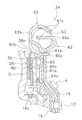
록업 장치(7)는, 프론트 커버(2)와 터빈(4)의 사이에 배치되고, 프론트 커버(2)로부터 터빈(4)에 동력을 직접 전달하는 것이다. 이 록업 장치(7)는, 도 2에 확대하여 나타낸 바와 같이, 클러치 디스크(28)와, 프레셔 플레이트(29)와, 피스톤(30)과, 피스톤 작동 기구(31)와, 댐퍼 기구(34)를 가지고 있다.The
<클러치 디스크(28)>≪
클러치 디스크(28)는, 환형으로 형성되어 있고, 프론트 커버(2)의 마찰면(2b)에 압접 가능하다. 클러치 디스크(28)는, 환형의 코어 플레이트(36)와, 코어 플레이트(36)의 양측면에 고정된 환형의 마찰 부재(37)를 가지고 있다. 코어 플레이트(36)의 외주부는, 마찰 부재(37)의 외경보다 크고, 마찰 부재(37)로부터 외주측으로 돌출한 부분이 터빈측에 소정 각도로 구부려져 있다. 그리고, 이 구부러진 부분에, 복수의 걸어맞춤 돌기(36a)가 형성되어 있다.The
<프레셔 플레이트(29)>≪ Pressure plate (29) >
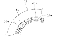
프레셔 플레이트(29)는, 클러치 디스크(28)과 피스톤(30)의 사이에 축 방향으로 이동 가능하도록 배치되어 있다. 프레셔 플레이트(29)는, 피스톤(30)에 의해 압압되고, 클러치 디스크(28)를 프론트 커버(2) 측으로 압압한다. 또한, 프레셔 플레이트(29)는, 환형으로 형성되어 있고, 외경은 클러치 디스크(28)의 마찰 부재(37)의 외경보다 크고, 내경(內徑)은 마찰 부재(37)의 내경보다 작다. 프레셔 플레이트(29)의 내주단부에는, 도 3에 확대하여 나타낸 바와 같이, 원주 방향에 소정의 간격으로 복수의 홈(29a)이 형성되어 있다. 각각의 홈(29a)은, 직경 방향으로 소정의 깊이를 가지고, 내주측이 개구되어 있다. 그리고, 도 4는 프레셔 플레이트(29)를 프론트 커버(2) 측로부터 본 도면이다.The
<피스톤(30)>≪
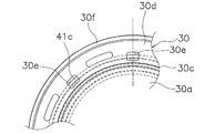
피스톤(30)은, 도 1 및 도 2에 나타낸 바와 같이, 프론트 커버(2)와 터빈(4)의 사이에 배치되고, 축 방향으로 이동 가능하다. 피스톤(30)은, 원판형의 수압부(受壓部)(30a)와, 제1 돌출부(30b)와, 제2 돌출부(30c)와, 외주 원판부(30d)를 가지고 있다. 그리고, 수압부(30a)와 외주 원판부(30d)에 의해 본체부가 형성되어 있다.1 and 2, the
수압부(30a)는 작동유의 압력을 받는 부분이며, 제1 돌출부(30b)는 수압부(30a)의 외주부에, 터빈(4) 측으로 돌출하여 형성되어 있다. 수압부(30a)의 외주단부는 프론트 커버(2) 측으로 경사지게 연장되어 있어, 제2 돌출부(30c)는, 이 경사지게 연장된 부분의 선단에, 프론트 커버(2) 측으로 더욱 돌출하여 형성되어 있다.The
외주 원판부(30d)는, 수압부(30a)와 일체로, 수압부(30a)에 대하여 프론트 커버측에 오프셋되어 있다. 도 4에 나타낸 바와 같이, 외주 원판부(30d)의 내주부에는, 원주 방향에 소정의 간격으로 복수의 개구(30e)가 형성되어 있다. 복수의 개구(30e)는 축 방향으로 관통하고 있다. 그리고, 도 4는 피스톤(30)을 프론트 커버(2) 측으로부터 본 도면이다.The outer
또한, 외주 원판부(30d)의 외주단부에는, 환형의 압압부(押壓部)(30f)가 형성되어 있다. 압압부(30f)는, 외주 원판부(30d)의 외주단부에, 프론트 커버(2) 측으로 돌출하여 형성되어 있다. 이 압압부(30f)는, 프레셔 플레이트(29)의 직경 방향의 폭의 대략 중앙부와 맞닿도록 형성되어 있다.An annular
<피스톤 작동 기구(31)>≪
피스톤(30)은, 피스톤 작동 기구(31)에 의해 축 방향으로 작동한다. 도 2에 나타낸 바와 같이, 피스톤 작동 기구(31)는, 지지용 보스(40)와, 커버 플레이트(유실 플레이트)(41)와, 리턴 기구(42)를 가지고 있다.The piston (30) is operated in the axial direction by the piston operating mechanism (31). 2, the
-지지용 보스(40)-- support boss (40) -
지지용 보스(40)는, 도 2 및 도 5에 나타낸 바와 같이, 프론트 커버(2)의 내주부에 고정되어 있다. 구체적으로는, 지지용 보스(40)는, 센터 보스(8)의 일부이며, 센터 보스(8)의 터빈(4) 측단부로부터 축 방향으로 연장되는 통형으로 형성되어 있다. 지지용 보스(40)는, 제1 고정부(40a)와, 피스톤 지지부(40b)와, 제2 고정부(40c)와, 제1 중간부(40d)와, 제2 중간부(40e)를 가지고 있다. 그리고, 도 5는 도 1의 확대 부분도이다.As shown in Figs. 2 and 5, the
제1 고정부(40a)는, 외주면에 프론트 커버(2)의 내주단면(內周端面)이 용접에 의해 고정되어 있다. 즉, 제1 고정부(40a)의 외주면에 프론트 커버(2)의 내주단면이 삽입되어 고정되어 있는 것에 의해, 센터 보스(8) 및 지지용 보스(40)에 대하여 프론트 커버(2)가 심출(芯出)되어 있다.The
피스톤 지지부(40b)는, 외경이 제1 고정부(40a)의 외경보다 크게 형성되어 있다. 피스톤 지지부(40b)의 외주면에는, 피스톤(30)의 내주단면이 축 방향으로 슬라이드 가능하게 지지되어 있다. 또한, 피스톤 지지부(40b)의 외주면에는, 실링 부재(45)가 장착되어 있다. 이 실링 부재(45)에 의해, 피스톤 지지부(40b)의 외주면과 피스톤(30)의 내주단면의 사이가 실링되어 있다. 그리고, 피스톤 지지부(40b)의 프론트 커버(2) 측의 측면은, 내주측으로 가는 것에 의해 프론트 커버(2) 측으로 근접하도록 경사지고 있다.The outer diameter of the
제2 고정부(40c)는, 외경이 피스톤 지지부(40b)의 외경보다 작다. 즉, 피스톤 지지부(40b)와 제2 고정부(40c)는 높이가 다르게 형성되어 있다. 이 제2 고정부(40c)의 외주면에, 커버 플레이트(41)의 내주단면이 용접에 의해 고정되어 있다. 제2 고정부(40c)의 외경을, 실링 부재(45)가 장착된 피스톤 지지부(40b)의 외경보다 작게 함으로써, 제2 고정부(40c)에 커버 플레이트(41)을 용접했을 때에도, 용접에 의한 피스톤 지지부(40b)의 불균일을 억제할 수 있다. 따라서, 피스톤 지지부(40b)와 피스톤(30)의 사이의 실링성(sealing performance)이 향상된다.The outer diameter of the
제1 중간부(40d)는, 제1 고정부(40a)와 피스톤 지지부(40b)의 사이에 형성되어 있다. 제1 중간부(40d)의 외주면은, 프론트 커버(2) 측으로부터 터빈(4) 측을 향하여 직경이 커지도록 경사지고 있다. 제1 중간부(40d)의 외주면의 최소 직경은 제1 고정부(40a)의 직경보다 크고, 최대 직경은 피스톤 지지부(40b)의 직경보다 작다.The first
제2 중간부(40e)는, 피스톤 지지부(40b)와 제2 고정부(40c)의 사이에 형성되어 있다. 제2 중간부(40e)의 외주면은, 프론트 커버(2) 측으로부터 터빈(4) 측을 향하여 직경이 작아지도록 경사지고 있다. 제2 중간부(40e)의 외주면의 최대 직경은 피스톤 지지부(40b)의 직경보다 작고, 최소 직경은 제2 고정부(40c)의 직경보다 크다.The second
그리고, 지지용 보스(40)의 터빈(4) 측의 단면과 터빈 허브(16)의 사이에는, 트러스트 와셔(46)가 배치되어 있다. 트러스트 와셔(46)의 표면에는, 적어도 하나의 직경 방향에 대한 홈이 형성되어 있다.A
-커버 플레이트(41)-- Cover plate (41) -
커버 플레이트(41)는, 프론트 커버(2)와의 사이에 피스톤(30)의 수압부(30a)를 협지하도록 배치되어 있다. 커버 플레이트(41)는, 도 2에 나타낸 바와 같이, 본체부(41a)와, 실링부(41b)와, 토크 전달부(41c)를 가지고 있다.The
본체부(41a)는, 원판형으로 형성되어 있고, 전술한 바와 같이, 내주단면이 지지용 보스(40)의 제2 고정부(40c)의 외주면에 용접에 의해 고정되어 있다.The
실링부(41b)는, 본체부(41a)의 외주부에 형성되어 있고, 터빈(4) 측으로 패인 오목부(41d)를 가지고 있다. 이 오목부(41d)에, 피스톤(30)의 제1 돌출부(30b)가 삽입되어 있다. 제1 돌출부(30b)의 외주부에는 실링 부재(47)가 장착되어 있고, 실링 부재(47)의 외주부가 오목부(41d)의 내주면과 맞닿아 있다. 따라서, 이 실링 부재(47)에 의해, 피스톤(30)과 커버 플레이트(41)의 사이에 록업용 유실(C1)이 형성되어 있다.The sealing
토크 전달부(41c)는, 실링부(41b)의 더욱 외주측에 형성되어 있다. 토크 전달부(41c)는, 실링부(41b)의 외주부으로부터 프론트 커버측으로 연장되는 복수의 걸어맞춤 돌기(이하, 「걸어맞춤 돌기(41c)」로 기재함)이다. 이 걸어맞춤 돌기(41c)는, 도 2 및 도 4에 나타낸 바와 같이, 피스톤(30)에 형성된 개구(30e)를 관통하고, 프레셔 플레이트(29)의 내주단부에 형성된 홈(29a)에 걸어맞추어져 있다. 도 6에, 커버 플레이트(41) 및 피스톤(30)을 터빈(4) 측로부터 본 사시도를 나타내고 있다.The
이와 같은 구성에 의해, 커버 플레이트(41)에 전달된 토크를, 프레셔 플레이트(29)에 전달할 수 있다. 또한, 토크 전달부로서의 걸어맞춤 돌기(41c)의 원주 방향의 치수와 피스톤(30)의 개구(30e)의 원주 방향의 치수를 적절하게 설정함으로써, 커버 플레이트(41)에 대한 피스톤(30)의 상대(相對) 회전을 규제할 수 있다.With this configuration, the torque transmitted to the
리턴 기구(42)는, 프론트 커버(2)와 피스톤(30)의 사이에 배치되어 있고, 피스톤(30)을 프론트 커버(2)의 마찰면으로부터 이격되는 방향으로 가압하는 기구이다. 또한, 리턴 기구(42)는, 피스톤(30)을 프론트 커버(2)로부터 이격하는 방향으로 가압하고, 또한 프론트 커버(2)의 마찰면(2b)과 피스톤(30)의 압압부(30f)의 사이의 간극을 조정하는 기능을 가지고 있다.The
구체적으로는, 분위기 온도가 저온인 경우에는, 피스톤(30)을 프론트 커버(2)로부터 이격하도록 이동시키고, 피스톤(30)과 프론트 커버(2)의 사이의 간극, 즉 클러치 디스크(28)가 설치된 부분의 간극(클러치 디스크(28)의 커팅 여유부)을 크게 한다. 따라서, 클러치 디스크(28) 부분에서의 드래그 토크를 작게 억제할 수 있다.Specifically, when the ambient temperature is low, the
한편, 분위기 온도가 높아지고, 예를 들면, 상온이 되면, 피스톤(30)을 프론트 커버(2)에 근접하도록 이동시킨다. 이에 따라, 피스톤(30)과 프론트 커버(2)의 사이의 간극, 즉 클러치 디스크(28)가 설치된 부분의 간극(클러치 디스크(28)의 커팅 여유부)이 작아진다. 따라서, 신속하게 록업시키는 것이 가능하다.On the other hand, when the ambient temperature becomes high, for example, at room temperature, the
<유압 회로><Hydraulic circuit>
피스톤 작동 기구(31)의 구성에 의해, 도 2에 나타낸 바와 같이, 피스톤(30)의 수압부(30a)와 커버 플레이트(41)의 본체부(41a)의 사이에는, 록업용 유실(C1)이 형성되어 있다. 또한, 프론트 커버(2)의 직경 방향 중간부와 내주부의 사이에는, 축 방향으로 연장되는 통형의 단차부(step part)(2c)가 형성되어 있고, 이 단차부(2c)의 외주면에는, 실링 부재(57)가 장착되어 있다. 실링 부재(57)는, 피스톤(30)의 제2 돌출부(30c)의 내주면과 맞닿아 있다. 따라서, 피스톤(30)의 수압부(30a)와 프론트 커버(2)의 사이에는, 록업 오프 시에 록업용 유실(C1)에서 발생하는 유압을 캔슬하기 위한 캔슬용 유실(C2)이 형성되어 있다.2, a lock-up oil chamber C1 is formed between the pressure-receiving
그리고, 프론트 커버(2)의 단차부(2c)에 장착된 실링 부재(57)는, 통상적인 실링 부재 (예를 들면, 제1 돌출부(30b)에 장착된 실링 부재(47)보다 실링 성능이 뒤떨어진다. 구체적으로는, 실링 부재(57)를 단차부(2c)에 장착한 상태에서도, 실링 부재(57)의 맞댐부의 간극이, 통상 설정되어 있는 간극보다 넓어지게 설정되어 있다. 이 때문에, 실링 부재(57)가 장착된 부분에서는, 다른 실링부에 비해 작동유의 누출량이 많아진다. 이로써, 캔슬용 유실(C2)에 작동유가 공급되고, 캔슬용 유실(C2)은 원하는 압력으로 설정된다.The sealing
지지용 보스(40)에는, 도 2 및 도 5에 나타낸 바와 같이, 직경 방향으로 관통하는 제1 유로(P1) 및 제2 유로(P2)가 형성되어 있다. 제1 유로(P1)는, 지지용 보스(40)의 제2 중간부(40e)의 경사면에 개구되고, 록업용 유실(C1)과 지지용 보스(40)의 내주부의 공간을 연통한다. 제2 유로(P2)는, 제1 중간부(40d)의 경사면에 개구되고, 캔슬용 유실(C2)과 지지용 보스(40)의 내주부의 공간을 연통한다. 칼라(18)에는, 환형의 홈(18a)이 형성되어 있고, 이 홈(18a)에, 직경 방향으로 관통하는 복수의 제3 유로(P3)가 형성되어 있다. 그리고, 제2 유로(P2)는 제3 유로(P3)와 연통되어 있다.As shown in Figs. 2 and 5, the
또한, 도 1에 나타낸 바와 같이, 제3 유로(P3)는, 트랜스미션의 입력축(도시하지 않음)의 내부를 관통하는 제4 유로(P4)와 연통되어 있다. 이 제4 유로(P4)는 트랜스미션의 배수 탱크(T)와 연통되어 있다. 제4 유로(P4)의 도중에는, 캔슬용 유실(C2)의 내부 압력을 소정의 압력으로 유지하기 위한 유압 유지 회로(캔슬 유압 유지 회로)(58)가 설치되어 있다.Further, as shown in Fig. 1, the third flow path P3 is in communication with a fourth flow path P4 passing through the inside of the input shaft (not shown) of the transmission. The fourth flow path P4 communicates with the drain tank T of the transmission. In the middle of the fourth flow path P4, there is provided a hydraulic pressure holding circuit (cancel hydraulic pressure holding circuit) 58 for keeping the internal pressure of the canceling oil chamber C2 at a predetermined pressure.
유압 유지 회로(58)는, 제4 유로(P4)의 출구 부분에 형성된 조리개(58a)와, 제4 유로(P4)에 연락 유로(P5)를 통하여 접속된 유압 공급원(58b)을 가지고 있다. 조리개(58a)는, 제4 유로(P4)의 일부를 소경으로 좁힌 오리피스(orifice) 등의 작동유의 흐름에 저항을 주는 구성이면 된다. 유압 공급원(58b)은, 유압 펌프나 압력 제어 밸브 등을 포함하고, 유로(P2, P3, P4) 및 캔슬용 유실(C2)이 소정의 압력으로 유지되도록 구성되어 있다.The hydraulic
<댐퍼 기구(34)>≪
댐퍼 기구(34)는, 클러치 디스크(28)와 터빈(4)의 사이에 배치되고, 클러치 디스크(28)로부터의 토크를 터빈(4)에 전달하는 것이다. 도 9에 나타낸 바와 같이, 댐퍼 기구(34)는, 걸어맞춤 부재(60)와, 드라이브 플레이트(61)와, 드리븐 플레이트(62)와, 복수의 토션 스프링(63)을 가지고 있다.The
걸어맞춤 부재(60)는, 고정부(60a)와, 각각 복수의 제1 걸어맞춤부(60b) 및 제2 걸어맞춤부(60c)를 가지고 있다. 고정부(60a)는, 환형으로 형성되고, 리벳(65)에 의해 드라이브 플레이트(61)에 고정되어 있다. 복수의 제1 걸어맞춤부(60b)는, 고정부(60a)의 외주단을 프론트 커버(2) 측으로 구부려서 형성되어 있고, 클러치 디스크(28)의 코어 플레이트(36)의 외주에 형성된 걸어맞춤 돌기(36a)에 맞물려 있다. 클러치 디스크(28)는, 제1 걸어맞춤부(60b)에 대하여, 축 방향으로는 이동 가능하며, 상대 회전은 금지되어 있다. 복수의 제2 걸어맞춤부(60c)는, 고정부(60a)의 외주단을 터빈(4) 측으로 구부려서 형성되어 있다.The engaging
드라이브 플레이트(61)는, 환형으로 형성되어 있고, 피스톤(30)과 터빈(4)의 사이에 배치되어 있다. 드라이브 플레이트(61)는, 걸어맞춤 부재(60)에 전달된 토크를 토션 스프링(63)에 전달한다. 드라이브 플레이트(61)는, 원판부(61a)와, 복수의 지지부(61b)와, 복수의 걸어맞춤부(61c)를 가지고 있다.The
원판부(61a)의 내주단면은, 터빈(4) 측으로 구부러져, 위치 결정부(61d)가 되어 있다. 이 위치 결정부(61d)가, 터빈 허브(16)의 외주단부에 형성된 댐퍼 지지부(16c)에 의해 지지되어, 직경 방향 및 축 방향으로 위치 결정되어 있다. 원판부(61a)의 외주부에는, 축 방향으로 관통하는 구멍(61e)이 형성되어 있다. 이 구멍(61e)을, 걸어맞춤 부재(60)의 제2 걸어맞춤부(60c)가 관통하고, 터빈(4) 측으로 연장되어 있다.The inner peripheral end surface of the
지지부(61b)는, 원판부(61a)의 외주부에 형성되고, 단면 C자형이다. 이 지지부(61b)에, 복수의 토션 스프링(63)이 수용되어 있고, 지지부(61b)에 의해, 토션 스프링(63)의 직경 방향 및 프론트 커버(2) 측으로의 이동이 규제되고 있다.The
걸어맞춤부(61c)는, 원판부(61a)의 외주부에 있어서, 인접하는 지지부(61b)의 사이에 형성되어 있다. 걸어맞춤부(61c)의 일부가, 지지부(61b)에 수용된 토션 스프링(63)의 양 단면에 걸어맞추어져 있다.The engaging
드리븐 플레이트(62)는, 대략 원판형으로 형성되어 있고, 드라이브 플레이트(61)과 터빈(4)의 사이에 배치되어 있다. 드리븐 플레이트(62)는, 토션 스프링(63)에 전달된 토크를 터빈 허브(16)에 전달하는 것이다. 드리븐 플레이트(62)는, 내주단부가 리벳(17)에 의해 터빈 쉘(14) 및 터빈 허브(16)에 고정되어 있다. 또한, 드리븐 플레이트(62)는, 터빈 쉘(14)의 측면을 따라 외주측으로 연장되어 있고, 외주부에 형성된 걸어맞춤부(62a)가 토션 스프링(63)의 양단면에 걸어맞추어져 있다.The
[동작][action]
록업 장치(7)에 있어서, 록업을 해제(클러치 오프=록업 오프)할 경우에는, 록업용 유실(C1)은 드레인에 접속된다. 따라서, 록업용 유실(C1) 내의 작동유는, 제1 유로(P1)를 통하여 탱크(T) 측으로 되돌려진다. 이와 같은 상태에서는, 피스톤(30)은, 리턴 기구(42)에 의해 터빈(4) 측으로 이동하고, 피스톤(30)의 압압부(30f)에 의한 프레셔 플레이트로의 압압력이 해제된다. 따라서, 록업 오프(동력 전달이 해제된 상태)이며, 프론트 커버(2)로부터의 토크는, 작동유를 통하여 임펠러(3)로부터 터빈(4)에 전달되고, 터빈 허브(16)를 통하여 트랜스미션의 입력 샤프트에 전달된다.In the
그리고, 이 록업 오프 시에, 록업용 유실(C1)에 잔존하는 작동유에 원심력이 작용하고, 이로써 피스톤(30)이 프론트 커버(2) 측으로 가압되는 경우가 있다. 피스톤(30)이 프론트 커버(2) 측으로 이동하면, 클러치 디스크(28)에 의한 드래그 토크가 커진다.In this case, centrifugal force acts on the operating fluid remaining in the lockup chamber C1, thereby pushing the
그래서, 이 장치에서는, 전술한 바와 같이, 실링 부재(57)로부터의 누출량이, 통상의 누출량보다 많아지도록 하고 있다. 이 때문에, 실링 부재(57)로부터 누출된 작동유가 캔슬용 유실(C2)로 침입하여, 피스톤(30)의 프론트 커버(2) 측으로의 이동을 억제하고 있다. 즉, 록업용 유실(C1)에서의 작동유의 원심력에 의해 작용하는 피스톤(30)으로의 압압력을, 실링 부재(57)로부터 캔슬용 유실(C2)로 누출되는 작동유에 의해 캔슬하도록 하고 있다. 캔슬용 유실(C2)에서는, 실링 부재(57)로부터 침입하는 작동유에 의해, 또한 유압 유지 회로(58)의 작용에 의해, 소정의 유압으로 유지된다.Thus, in this apparatus, as described above, the leakage amount from the sealing
그리고, 실링 부재(57)의 간극이 이물질 등에 의해 막혔을 경우, 캔슬용 유실(C2)에는 실링 부재(57)를 통하여 작동유가 침입하지 않게 된다. 그러나, 이러한 경우라도, 유압 유지 회로(58)에 의해, 제2∼제4 유로(P2, P3, P4) 및 캔슬용 유실(C2)의 유압은, 소정의 유압으로 유지된다.When the gap of the sealing
한편, 록업 장치(7)에 있어서, 록업 온(클러치 온=동력 전달 상태)으로 하는 경우에는, 록업용 유실(C1)에 작동유를 공급한다. 즉, 칼라(18)의 단면에 작동유를 공급하고, 또한 제1 유로(P1)를 통하여, 작동유를 록업용 유실(C1)에 공급한다. 이로써, 피스톤(30)은 프론트 커버(2) 측으로 이동하고, 프레셔 플레이트(29)를 프론트 커버(2) 측으로 이동시킨다. 이에 따라, 클러치 디스크(28)가 프론트 커버(2)와 프레셔 플레이트(29)의 사이에 협지되어, 록업 온의 상태가 된다.On the other hand, in the
록업 온의 상태에서는, 프론트 커버(2)로부터의 토크는, 지지용 보스(40)→커버 플레이트(41)→프레셔 플레이트(29)→클러치 디스크(28)의 경로를 통하여, 또한 프론트 커버(2)로부터 클러치 디스크(28)를 통하여 댐퍼 기구(34)에 전달된다.The torque from the
또한, 이 록업 온 상태의 경우에도, 실링 부재(57)를 통하여 캔슬용 유실(C2)에는 작동유가 침입한다. 이 때문에, 전술한 바와 같이, 캔슬용 유실(C2)은 소정의 유압이 되고, 토크 컨버터 본체(6)의 내압 변동에 의한 록업 클러치의 체결력 변동을 억제할 수 있다.Further, even in the lockup-on state, the working oil enters the cancellation oil chamber C2 through the sealing
그리고, 실링 부재(57)가 이물질 등에 의해 막힌 경우라도, 전술한 바와 마찬가지로, 유압 유지 회로(58)에 의해 캔슬용 유실(C2)의 압력을 소정의 압력으로 유지할 수 있다.Even when the sealing
댐퍼 기구(34)에 있어서는, 걸어맞춤 부재(60)에 입력된 토크는, 토션 스프링(63) 및 드리븐 플레이트(62)를 통하여 터빈(4)에 전달되고, 또한 터빈 허브(16)를 통하여 트랜스미션의 입력 샤프트에 전달된다.In the
[다른 실시형태][Other Embodiments]
본 발명은 이상과 같은 실시형태로 한정되지 않고, 본 발명의 범위를 일탈하지 않고 각종 변형 또는 수정이 가능하다.The present invention is not limited to the above-described embodiments, and various modifications and changes may be made without departing from the scope of the present invention.
(a) 다른 실시형태에 의한 유로 유지 회로(58')를 도 8에 나타내고 있다. 여기서는, 상기 실시형태의 제4 유로(P4) 대신, 제4 유로(P40)가 설치되어 있다. 제4 유로(P40)는, 제3 유로(P3)와 연통되고, 또한 트랜스미션의 입력축(도시하지 않음)의 내부에 설치되어 있다. 제4 유로(P40)는, 트랜스미션의 배수 탱크(T)와 연통되어 있고, 그 일부에 상부 유로(P40a)를 가지고 있다. 상부 유로(P40a)는, 토크 컨버터의 회전축 O-O보다 상방에 위치하도록 배치되어 있다.(a) A channel holding circuit 58 'according to another embodiment is shown in Fig. Here, a fourth flow path P40 is provided instead of the fourth flow path P4 in the above-described embodiment. The fourth flow path P40 communicates with the third flow path P3 and is provided inside the input shaft (not shown) of the transmission. The fourth flow path P40 communicates with the drain tank T of the transmission and has an upper flow path P40a in a part thereof. The upper flow path P40a is arranged so as to be located above the rotation axis O-O of the torque converter.
그리고, 유압 유지 회로(58')의 다른 구성은 상기 실시형태와 동일하다. 즉, 유압 유지 회로(58')는, 제4 유로(P40)의 출구 부분에 형성된 조리개(58a)와, 제4유로(P40)에 연락 유로(P5)를 통하여 접속된 유압 공급원(58b)을 가지고 있다. 조리개(58a)는, 제4 유로(P40)의 일부를 소경으로 좁힌 오리피스 등의 작동유의 흐름에 저항을 주는 구성이면 된다. 유압 공급원(58b)은, 유압 펌프나 압력 제어 밸브 등을 포함하고, 유로(P2, P3, P40) 및 캔슬용 유실(C2)이 소정의 압력으로 유지되도록 구성되어 있다.The other configuration of the hydraulic pressure holding circuit 58 'is the same as that of the above embodiment. That is, the oil pressure holding circuit 58 'includes a
이러한 실시형태에 있어서도, 상기 실시형태와 동일한 작용 효과를 얻을 수 있다.Also in this embodiment, the same operational effects as those of the above embodiment can be obtained.
(b) 록업용 유실 및 캔슬용 유실의 배치나, 이 유실과 연통하는 유로의 배치는, 상기 실시형태로 한정되지 않고, 상기 실시형태와는 축 방향에 있어서 반대로 배치되고 있어도 된다. (b) Arrangement of oil chamber for lock-up and cancellation and arrangement of oil passage for communicating with oil chamber is not limited to the above-described embodiment, but may be reversed in the axial direction from the above-described embodiment.
[산업상의 이용가능성][Industrial Availability]
본 발명에서는, 캔슬용의 유실을 구비한 록업 장치에 있어서, 캔슬용 유실의 유압을, 안정적으로 원하는 유압으로 유지할 수 있다. According to the present invention, in the lock-up device provided with the oil chamber for cancellation, the oil pressure of the oil chamber for cancellation can be stably maintained at a desired oil pressure.
2: 프론트 커버
2b: 마찰면
28: 클러치 디스크
30: 피스톤
40: 지지용 보스
41: 커버 플레이트(유실 플레이트)
58, 58': 유압 유지 회로
58a: 오리피스(조리개)
C1: 록업용 유실
C2: 캔슬용 유실
P1: 제1 유로
P2: 제2 유로
P3: 제3 유로
P4, P40: 제4 유로
P40a: 상부 유로2: Front cover
2b: friction surface
28: Clutch disc
30: Piston
40: support boss
41: Cover plate (oil chamber plate)
58, 58 ': Hydraulic holding circuit
58a: Orifice (aperture)
C1: Loss of lockup
C2: cancellation chamber
P1: First Euro
P2: the second channel
P3: Third Euro
P4, P40: the fourth channel
P40a:
Claims (6)
상기 프론트 커버와 상기 트랜스미션 측의 부재의 동력 전달 경로에 배치된 클러치부;
축 방향으로 이동 가능하게 설치된 피스톤;
상기 피스톤을 이동시켜 상기 클러치부를 동력 전달 상태로 하기 위한 작동유가 공급되는 록업용 유실(油室);
상기 피스톤을 협지하여 상기 록업용 유실과 반대측에 설치되고, 상기 작동유가 공급되는 캔슬용 유실(cancellation oil chamber); 및
상기 캔슬용 유실로부터 배출된 상기 작동유를 상기 트랜스미션 측으로 인도하는 유로(油路)에 설치되고, 상기 캔슬용 유실을 소정의 유압으로 유지하는 캔슬 유압 유지 회로;
를 포함하는 토크 컨버터의 록업 장치.A lockup device for a torque converter for transmitting a torque input to a front cover to a member on a transmission side,
A clutch portion disposed in the power transmission path of the front cover and the transmission side member;
A piston movably disposed in the axial direction;
A lockup oil chamber to which the operating oil is supplied for moving the piston to transmit the power to the clutch portion;
A cancellation oil chamber provided on the side opposite to the lock-up oil chamber with the piston interposed therebetween and supplied with the operating oil; And
A cancel oil pressure holding circuit which is provided in an oil path for leading the hydraulic oil discharged from the oil mist canceling chamber to the transmission side and holds the cancel oil mist chamber at a predetermined oil pressure;
Up device of the torque converter.
상기 캔슬용 유실의 외주부(外周部)에 설치된 제1 실링 부재; 및
상기 캔슬용 유실의 내주부(內周部)에 설치된 제2 실링 부재;
를 더 포함하고,
상기 캔슬용 유실에는 상기 제1 실링 부재의 간극을 통하여 상기 작동유가 공급되는, 토크 컨버터의 록업 장치.The method according to claim 1,
A first sealing member provided on an outer peripheral portion of the canceling oil chamber; And
A second sealing member provided on an inner circumferential portion of the canceling oil chamber;
Further comprising:
And the operating oil is supplied to the canceling oil chamber through the gap of the first sealing member.
상기 프론트 커버의 내주부에 축 방향으로 돌출되어 고정되고, 또한 외주면에 상기 피스톤이 축 방향으로 슬라이드 가능하게 지지된 환형(環形)의 지지용 보스(boss); 및
상기 지지용 보스의 외주면에, 상기 프론트 커버와의 사이에 상기 피스톤을 협지하도록 고정되고, 상기 피스톤과의 사이에 상기 록업용 유실을 구성하는 원판형의 유실 플레이트;
를 더 포함하는 토크 컨버터의 록업 장치.3. The method according to claim 1 or 2,
An annular support boss fixed to an inner circumferential portion of the front cover in an axial direction and fixed to the outer circumferential surface of the boss, the piston being slidably supported in an axial direction; And
A disk-shaped oil chamber plate fixed to an outer circumferential surface of the support boss so as to sandwich the piston between the front cover and the front cover, and constituting the lock-up oil chamber with the piston;
Up device of the torque converter.
상기 캔슬용 유실은 상기 프론트 커버와 상기 피스톤의 사이에 배치되고,
상기 지지용 보스에는, 상기 록업용 유실 및 상기 캔슬용 유실의 각각에
연통하는 유로가 형성되어 있는, 토크 컨버터의 록업 장치. The method of claim 3,
Wherein the canceling oil chamber is disposed between the front cover and the piston,
The supporting boss is provided with a lock bushing
Wherein a communication passage is formed.
상기 캔슬 유압 유지 회로는, 상기 캔슬용 유실로부터 배출된 상기 작동유를 상기 트랜스미션 측으로 인도하는 유로에 설치된 조리개(restrictor)를 포함하는, 토크 컨버터의 록업 장치.5. The method according to any one of claims 1 to 4,
Wherein the cancel hydraulic pressure holding circuit includes a restrictor provided in a flow path for guiding the hydraulic fluid discharged from the canceling oil chamber to the transmission side.
상기 캔슬 유압 유지 회로는, 상기 토크 컨버터의 회전축보다 상방(上方)에 위치하는 상부 유로를 가지고, 상기 상부 유로는, 상기 캔슬용 유실로부터 배출된 상기 작동유를 상기 트랜스미션 측으로 인도하는 유로의 일부에 설치되어 있는, 토크 컨버터의 록업 장치.6. The method of claim 5,
The cancel oil pressure holding circuit has an upper oil passage located above (above) the rotary shaft of the torque converter, and the upper oil passage is provided in a part of the oil passage leading the operating oil discharged from the cancellation oil chamber to the transmission side Up device of the torque converter.
Applications Claiming Priority (5)
| Application Number | Priority Date | Filing Date | Title |
|---|---|---|---|
| JP2015161941 | 2015-08-19 | ||
| JPJP-P-2015-161941 | 2015-08-19 | ||
| JP2016059035A JP6608317B2 (en) | 2015-08-19 | 2016-03-23 | Torque converter lockup device |
| JPJP-P-2016-059035 | 2016-03-23 | ||
| PCT/JP2016/071238 WO2017029927A1 (en) | 2015-08-19 | 2016-07-20 | Lock-up apparatus for torque converter |
Publications (1)
| Publication Number | Publication Date |
|---|---|
| KR20180042161A true KR20180042161A (en) | 2018-04-25 |
Family
ID=58206539
Family Applications (1)
| Application Number | Title | Priority Date | Filing Date |
|---|---|---|---|
| KR1020177036369A KR20180042161A (en) | 2015-08-19 | 2016-07-20 | Lockup device of torque converter |
Country Status (5)
| Country | Link |
|---|---|
| US (1) | US20180163837A1 (en) |
| JP (1) | JP6608317B2 (en) |
| KR (1) | KR20180042161A (en) |
| CN (1) | CN107923505A (en) |
| DE (1) | DE112016002688T5 (en) |
Families Citing this family (5)
| Publication number | Priority date | Publication date | Assignee | Title |
|---|---|---|---|---|
| JP7043312B2 (en) * | 2018-03-28 | 2022-03-29 | 株式会社エクセディ | Vehicle drive |
| US11187312B2 (en) * | 2019-06-13 | 2021-11-30 | Schaeffler Technologies AG & Co. KG | Torque converter with stacked plate four-pass clutch |
| CN110985663B (en) * | 2020-02-27 | 2020-07-14 | 盛瑞传动股份有限公司 | Hydraulic torque converter control system, transmission and automobile |
| JP7477370B2 (en) * | 2020-06-01 | 2024-05-01 | 株式会社エクセディ | Lock-up Device |
| US11592091B1 (en) * | 2022-02-09 | 2023-02-28 | Schaeffler Technologies AG & Co. KG | Torque converter assembly including thrust washer |
Family Cites Families (6)
| Publication number | Priority date | Publication date | Assignee | Title |
|---|---|---|---|---|
| DE19508613A1 (en) * | 1995-03-10 | 1996-09-12 | Fichtel & Sachs Ag | Hydrodynamic torque converter with pump impeller driven by IC engine |
| US6367605B1 (en) * | 1998-07-20 | 2002-04-09 | Luk Getriebe-Systeme Gmbh | Hydrokinetic torque converter with lockup clutch |
| JP2005282617A (en) * | 2004-03-26 | 2005-10-13 | Aisin Seiki Co Ltd | Torque converter with lock-up clutch |
| DE102004060257A1 (en) * | 2004-12-15 | 2006-07-06 | Zf Friedrichshafen Ag | Hydrodynamic coupling device |
| JP5584249B2 (en) * | 2012-04-10 | 2014-09-03 | 株式会社エクセディ | Torque converter lockup device |
| KR20140030762A (en) * | 2012-09-03 | 2014-03-12 | 현대자동차주식회사 | A hydraulic control apparatus for hydraulic torque converter |
-
2016
- 2016-03-23 JP JP2016059035A patent/JP6608317B2/en active Active
- 2016-07-20 US US15/576,753 patent/US20180163837A1/en not_active Abandoned
- 2016-07-20 CN CN201680046926.1A patent/CN107923505A/en active Pending
- 2016-07-20 KR KR1020177036369A patent/KR20180042161A/en unknown
- 2016-07-20 DE DE112016002688.9T patent/DE112016002688T5/en not_active Withdrawn
Also Published As
| Publication number | Publication date |
|---|---|
| JP2017040361A (en) | 2017-02-23 |
| JP6608317B2 (en) | 2019-11-20 |
| DE112016002688T5 (en) | 2018-03-08 |
| CN107923505A (en) | 2018-04-17 |
| US20180163837A1 (en) | 2018-06-14 |
Similar Documents
| Publication | Publication Date | Title |
|---|---|---|
| KR20180042161A (en) | Lockup device of torque converter | |
| JP5401821B2 (en) | Starting device | |
| KR102017093B1 (en) | Lock-up device for torque converter | |
| JP5258952B2 (en) | Torque converter lockup device | |
| JP2017040361A5 (en) | ||
| JP5202718B1 (en) | Torque converter lockup device | |
| JP2013117283A (en) | Lockup device for torque converter | |
| KR102323869B1 (en) | Lock-up device for torque converter | |
| JP6173814B2 (en) | clutch | |
| KR20180011088A (en) | Lockup device of torque converter | |
| KR102327513B1 (en) | Lock-up device for torque converter | |
| JP6639807B2 (en) | Lockup device for torque converter | |
| WO2017029927A1 (en) | Lock-up apparatus for torque converter | |
| JP2016153659A (en) | Fluid joint | |
| US10634228B2 (en) | Torque converter | |
| JP2016217447A (en) | Lock-up device of torque converter | |
| JP6473044B2 (en) | Torque converter lockup device | |
| JP7099870B2 (en) | Hydraulic clutch device | |
| WO2016163172A1 (en) | Fluid coupling | |
| JP2016217446A (en) | Lock-up device of torque converter | |
| JP4978536B2 (en) | Starting device | |
| JP2021071124A (en) | Starting device |