JP6608317B2 - Torque converter lockup device - Google Patents
Torque converter lockup device Download PDFInfo
- Publication number
- JP6608317B2 JP6608317B2 JP2016059035A JP2016059035A JP6608317B2 JP 6608317 B2 JP6608317 B2 JP 6608317B2 JP 2016059035 A JP2016059035 A JP 2016059035A JP 2016059035 A JP2016059035 A JP 2016059035A JP 6608317 B2 JP6608317 B2 JP 6608317B2
- Authority
- JP
- Japan
- Prior art keywords
- oil
- oil chamber
- piston
- front cover
- lockup
- Prior art date
- Legal status (The legal status is an assumption and is not a legal conclusion. Google has not performed a legal analysis and makes no representation as to the accuracy of the status listed.)
- Active
Links
Images

Classifications
-
- F—MECHANICAL ENGINEERING; LIGHTING; HEATING; WEAPONS; BLASTING
- F16—ENGINEERING ELEMENTS AND UNITS; GENERAL MEASURES FOR PRODUCING AND MAINTAINING EFFECTIVE FUNCTIONING OF MACHINES OR INSTALLATIONS; THERMAL INSULATION IN GENERAL
- F16H—GEARING
- F16H45/00—Combinations of fluid gearings for conveying rotary motion with couplings or clutches
- F16H45/02—Combinations of fluid gearings for conveying rotary motion with couplings or clutches with mechanical clutches for bridging a fluid gearing of the hydrokinetic type
-
- F—MECHANICAL ENGINEERING; LIGHTING; HEATING; WEAPONS; BLASTING
- F16—ENGINEERING ELEMENTS AND UNITS; GENERAL MEASURES FOR PRODUCING AND MAINTAINING EFFECTIVE FUNCTIONING OF MACHINES OR INSTALLATIONS; THERMAL INSULATION IN GENERAL
- F16H—GEARING
- F16H41/00—Rotary fluid gearing of the hydrokinetic type
- F16H41/24—Details
-
- F—MECHANICAL ENGINEERING; LIGHTING; HEATING; WEAPONS; BLASTING
- F16—ENGINEERING ELEMENTS AND UNITS; GENERAL MEASURES FOR PRODUCING AND MAINTAINING EFFECTIVE FUNCTIONING OF MACHINES OR INSTALLATIONS; THERMAL INSULATION IN GENERAL
- F16H—GEARING
- F16H61/00—Control functions within control units of change-speed- or reversing-gearings for conveying rotary motion ; Control of exclusively fluid gearing, friction gearing, gearings with endless flexible members or other particular types of gearing
- F16H61/14—Control of torque converter lock-up clutches
-
- F—MECHANICAL ENGINEERING; LIGHTING; HEATING; WEAPONS; BLASTING
- F16—ENGINEERING ELEMENTS AND UNITS; GENERAL MEASURES FOR PRODUCING AND MAINTAINING EFFECTIVE FUNCTIONING OF MACHINES OR INSTALLATIONS; THERMAL INSULATION IN GENERAL
- F16H—GEARING
- F16H41/00—Rotary fluid gearing of the hydrokinetic type
- F16H41/24—Details
- F16H2041/246—Details relating to one way clutch of the stator
-
- F—MECHANICAL ENGINEERING; LIGHTING; HEATING; WEAPONS; BLASTING
- F16—ENGINEERING ELEMENTS AND UNITS; GENERAL MEASURES FOR PRODUCING AND MAINTAINING EFFECTIVE FUNCTIONING OF MACHINES OR INSTALLATIONS; THERMAL INSULATION IN GENERAL
- F16H—GEARING
- F16H45/00—Combinations of fluid gearings for conveying rotary motion with couplings or clutches
- F16H45/02—Combinations of fluid gearings for conveying rotary motion with couplings or clutches with mechanical clutches for bridging a fluid gearing of the hydrokinetic type
- F16H2045/0205—Combinations of fluid gearings for conveying rotary motion with couplings or clutches with mechanical clutches for bridging a fluid gearing of the hydrokinetic type two chamber system, i.e. without a separated, closed chamber specially adapted for actuating a lock-up clutch
-
- F—MECHANICAL ENGINEERING; LIGHTING; HEATING; WEAPONS; BLASTING
- F16—ENGINEERING ELEMENTS AND UNITS; GENERAL MEASURES FOR PRODUCING AND MAINTAINING EFFECTIVE FUNCTIONING OF MACHINES OR INSTALLATIONS; THERMAL INSULATION IN GENERAL
- F16H—GEARING
- F16H45/00—Combinations of fluid gearings for conveying rotary motion with couplings or clutches
- F16H45/02—Combinations of fluid gearings for conveying rotary motion with couplings or clutches with mechanical clutches for bridging a fluid gearing of the hydrokinetic type
- F16H2045/0215—Details of oil circulation
-
- F—MECHANICAL ENGINEERING; LIGHTING; HEATING; WEAPONS; BLASTING
- F16—ENGINEERING ELEMENTS AND UNITS; GENERAL MEASURES FOR PRODUCING AND MAINTAINING EFFECTIVE FUNCTIONING OF MACHINES OR INSTALLATIONS; THERMAL INSULATION IN GENERAL
- F16H—GEARING
- F16H45/00—Combinations of fluid gearings for conveying rotary motion with couplings or clutches
- F16H45/02—Combinations of fluid gearings for conveying rotary motion with couplings or clutches with mechanical clutches for bridging a fluid gearing of the hydrokinetic type
- F16H2045/0221—Combinations of fluid gearings for conveying rotary motion with couplings or clutches with mechanical clutches for bridging a fluid gearing of the hydrokinetic type with damping means
-
- F—MECHANICAL ENGINEERING; LIGHTING; HEATING; WEAPONS; BLASTING
- F16—ENGINEERING ELEMENTS AND UNITS; GENERAL MEASURES FOR PRODUCING AND MAINTAINING EFFECTIVE FUNCTIONING OF MACHINES OR INSTALLATIONS; THERMAL INSULATION IN GENERAL
- F16H—GEARING
- F16H45/00—Combinations of fluid gearings for conveying rotary motion with couplings or clutches
- F16H45/02—Combinations of fluid gearings for conveying rotary motion with couplings or clutches with mechanical clutches for bridging a fluid gearing of the hydrokinetic type
- F16H2045/0273—Combinations of fluid gearings for conveying rotary motion with couplings or clutches with mechanical clutches for bridging a fluid gearing of the hydrokinetic type characterised by the type of the friction surface of the lock-up clutch
- F16H2045/0294—Single disk type lock-up clutch, i.e. using a single disc engaged between friction members
Landscapes
- Engineering & Computer Science (AREA)
- General Engineering & Computer Science (AREA)
- Mechanical Engineering (AREA)
- Control Of Fluid Gearings (AREA)
- Hydraulic Clutches, Magnetic Clutches, Fluid Clutches, And Fluid Joints (AREA)
Description
本発明は、ロックアップ装置、特に、フロントカバーからのトルクをトランスミッション側の部材に伝達するためのトルクコンバータのロックアップ装置に関する。 The present invention relates to a lockup device, and more particularly, to a torque converter lockup device for transmitting torque from a front cover to a member on a transmission side.
トルクコンバータには、トルクをフロントカバーからタービンに直接伝達するためのロックアップ装置が設けられている場合が多い。ロックアップ装置は、フロントカバーとタービンとの間に配置されたクラッチ部と、軸方向に移動自在なピストンと、を有している。そして、ピストンを油圧によって移動させることにより、クラッチ部を動力伝達状態(クラッチオン=ロックアップ)及び動力伝達の解除状態(クラッチオフ=ロックアップオフ)にすることができる。 In many cases, the torque converter is provided with a lock-up device for transmitting torque directly from the front cover to the turbine. The lockup device includes a clutch portion disposed between the front cover and the turbine, and a piston that is movable in the axial direction. Then, by moving the piston by hydraulic pressure, the clutch portion can be brought into a power transmission state (clutch on = lock up) and a power transmission released state (clutch off = lock up off).
特許文献1に示されたロックアップ装置では、フロントカバーとピストンとの間にピストンを作動させるためのロックアップ用の油室が形成されている。そして、ピストンを挟んでロックアップ用の油室とは反対側に、内圧及び遠心力による油圧をキャンセルするためのキャンセル用の油室が形成されている。このキャンセル用油室に作動油が供給されることにより、トルクコンバータの内圧の変動によるロックアップクラッチの締結力の変動が抑制され、またクラッチオフ時にピストンに作用する遠心油圧がキャンセルされる。
In the lockup device disclosed in
特許文献1の装置では、キャンセル用油室の外周部に小径の連通孔が形成されている。そして、この連通孔を介してキャンセル用油室に作動油が供給されるようになっている。一般的に、キャンセル用油室に供給すべき作動油は少量であるために、特許文献1に示されるように連通孔は小径である。
In the device of
しかし、小径の連通孔は、異物等によって詰まりやすい。キャンセル用油室は、トランスミッションの入力軸の内周部又は外周部等を介してドレンされているので、連通孔が詰まってしまうと、キャンセル用油室に作動油がなくなってしまい、所望の油圧を得ることができない。そして、キャンセル用油室に所望の油圧が得られない場合は、内圧や遠心油圧のキャンセルをすることができなくなる。 However, the small-diameter communication holes are easily clogged with foreign substances. Since the cancellation oil chamber is drained via the inner or outer peripheral portion of the input shaft of the transmission, if the communication hole is clogged, the hydraulic oil disappears in the cancellation oil chamber and the desired hydraulic pressure is lost. Can't get. If the desired oil pressure cannot be obtained in the canceling oil chamber, the internal pressure and the centrifugal oil pressure cannot be canceled.
本発明の課題は、キャンセル用の油室を備えたロックアップ装置において、キャンセル用油室の油圧を、安定して所望の油圧に維持できるようにすることにある。 SUMMARY OF THE INVENTION An object of the present invention is to enable the oil pressure in a canceling oil chamber to be stably maintained at a desired oil pressure in a lock-up device having a canceling oil chamber.
本発明の第1側面に係るトルクコンバータのロックアップ装置は、フロントカバーに入力されたトルクをトランスミッション側の部材に伝達するための装置であって、クラッチ部と、ピストンと、ロックアップ用油室と、キャンセル用油室と、キャンセル油圧維持回路と、を備えている。クラッチ部はフロントカバーとトランスミッション側の部材との動力伝達経路に配置されている。ピストンは軸方向に移動自在に設けられている。ロックアップ用油室は、ピストンを移動させてクラッチ部を動力伝達状態にするための作動油が供給される。キャンセル用油室は、ピストンを挟んでロックアップ用油室と反対側に設けられ、作動油が供給される。キャンセル油圧維持回路は、キャンセル用油室から排出された作動油をトランスミッション側に導く油路に設けられ、キャンセル用油室を所定の油圧に維持する。 A torque converter lockup device according to a first aspect of the present invention is a device for transmitting torque input to a front cover to a member on a transmission side, and includes a clutch portion, a piston, and a lockup oil chamber. And a cancel oil chamber and a cancel oil pressure maintaining circuit. The clutch portion is disposed in a power transmission path between the front cover and the transmission side member. The piston is provided so as to be movable in the axial direction. The lockup oil chamber is supplied with hydraulic oil for moving the piston to bring the clutch portion into a power transmission state. The cancellation oil chamber is provided on the opposite side of the lockup oil chamber across the piston, and is supplied with hydraulic oil. The cancel hydraulic pressure maintaining circuit is provided in an oil passage that guides hydraulic oil discharged from the cancel oil chamber to the transmission side, and maintains the cancel oil chamber at a predetermined hydraulic pressure.
ここでは、ロックアップ用油室に作動油が供給され、ピストンが作動することによってクラッチ部が動力伝達状態になる。また、ピストンを挟んでロックアップ用油室の反対側にはキャンセル用油室が設けられており、このキャンセル用油室に作動油が供給されている。なお、キャンセル用油室の油圧は、ロックアップ用油室の油圧よりも低い。キャンセル用油室に作動油が供給されることによって、トルクコンバータの内圧の変動によるロックアップクラッチの締結力の変動が抑制され、またロックアップオフ時に、遠心油圧によってピストンがクラッチ部をロックアップさせる方向に移動することが防止される。 Here, the hydraulic oil is supplied to the lockup oil chamber, and the clutch is brought into a power transmission state by operating the piston. A canceling oil chamber is provided on the opposite side of the lockup oil chamber across the piston, and hydraulic oil is supplied to the canceling oil chamber. The oil pressure in the canceling oil chamber is lower than the oil pressure in the lockup oil chamber. By supplying hydraulic oil to the canceling oil chamber, fluctuations in the fastening force of the lockup clutch due to fluctuations in the internal pressure of the torque converter are suppressed, and when the lockup is off, the piston locks up the clutch part by centrifugal hydraulic pressure. It is prevented from moving in the direction.
キャンセル用油室には、小径の孔や隙間等を介して作動油が供給される。異物等によってこれらの孔や隙間が詰まった場合であっても、キャンセル油圧維持回路によって、キャンセル用油室が所望の油圧に維持される。このため、キャンセル用油室の機能を安定させることができる。 The canceling oil chamber is supplied with hydraulic oil through a small-diameter hole or gap. Even when these holes and gaps are clogged by foreign matter or the like, the cancel oil pressure maintaining circuit maintains the cancel oil chamber at a desired oil pressure. For this reason, the function of the cancellation oil chamber can be stabilized.
本発明の第2側面に係るトルクコンバータのロックアップ装置は、第1側面の装置において、キャンセル用油室の外周部に設けられた第1シール部材と、キャンセル用油室の内周部に設けられた第2シール部材と、をさらに備えている。そして、キャンセル用油室には第1シール部材の隙間を介して作動油が供給される。 The lock-up device for a torque converter according to the second aspect of the present invention is the first seal device provided in the outer peripheral portion of the canceling oil chamber and the inner peripheral portion of the canceling oil chamber in the first side device. A second sealing member. Then, the hydraulic oil is supplied to the canceling oil chamber through the gap of the first seal member.
本発明の第3側面に係るトルクコンバータのロックアップ装置は、第1又は第2側面の装置において、環状の支持用ボスと、円板状の油室プレートと、をさらに備えている。支持用ボスは、フロントカバーの内周部に軸方向に突出して固定されるとともに、外周面にピストンが軸方向に摺動可能に支持されている。油室プレートは、支持用ボスの外周面に、フロントカバーとの間にピストンを挟むように固定され、ピストンとの間にロックアップ用油室を構成する。 The torque converter lock-up device according to the third aspect of the present invention is the device of the first or second aspect, further comprising an annular support boss and a disk-shaped oil chamber plate. The support boss projects and is fixed in an axial direction to the inner peripheral portion of the front cover, and a piston is supported on the outer peripheral surface so as to be slidable in the axial direction. The oil chamber plate is fixed to the outer peripheral surface of the supporting boss so as to sandwich the piston between the oil cover plate and the front cover, and constitutes a lockup oil chamber between the piston and the piston.
本発明の第4側面に係るトルクコンバータのロックアップ装置は、第3側面の装置において、キャンセル用油室はフロントカバーとピストンとの間に配置され、支持用ボスには、ロックアップ用油室及び前記キャンセル用油室のそれぞれに連通する油路が形成されている。 A lockup device for a torque converter according to a fourth aspect of the present invention is the third aspect, wherein the canceling oil chamber is disposed between the front cover and the piston, and the supporting boss includes a lockup oil chamber. And an oil passage communicating with each of the cancellation oil chambers.
本発明の第5側面に係るトルクコンバータのロックアップ装置は、第1から第4側面のいずれかの装置において、キャンセル油圧維持回路は、キャンセル用油室から排出された作動油をトランスミッション側に導く油路に設けられた絞りを有する。 In the torque converter lockup device according to the fifth aspect of the present invention, in any one of the first to fourth aspects, the cancel hydraulic pressure maintaining circuit guides the hydraulic oil discharged from the cancel oil chamber to the transmission side. It has a restriction provided in the oil passage.
本発明の第6側面に係るトルクコンバータのロックアップ装置は、第5側面の装置において、キャンセル油圧維持回路は、トルクコンバータの回転軸より上方に位置する上部油路を有し、上部油路は、キャンセル用油室から排出された作動油をトランスミッション側に導く油路の一部に設けられている。 A lockup device for a torque converter according to a sixth aspect of the present invention is the fifth aspect of the device according to the fifth aspect, wherein the cancel hydraulic pressure maintaining circuit has an upper oil passage located above the rotation shaft of the torque converter, The hydraulic oil discharged from the canceling oil chamber is provided in a part of the oil passage that guides the hydraulic oil to the transmission side.
以上のような本発明では、キャンセル用の油室を備えたロックアップ装置において、キャンセル用油室の油圧を、安定して所望の油圧に維持することができる。 In the present invention as described above, in the lockup device including the canceling oil chamber, the oil pressure in the canceling oil chamber can be stably maintained at a desired oil pressure.
[トルクコンバータの全体構成]
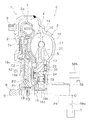
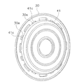
図1は本発明の一実施形態が採用されたトルクコンバータ1の縦断面図である。トルクコンバータ1は、エンジンのクランクシャフトからトランスミッションの入力シャフトにトルクを伝達するための装置である。図1の左側に図示しないエンジンが配置され、図1の右側に図示しないトランスミッションが配置されている。図1に示すO−Oがトルクコンバータ1の回転軸である。
[Overall configuration of torque converter]
FIG. 1 is a longitudinal sectional view of a
トルクコンバータ1は、主に、フロントカバー2と、3種の羽根車(インペラ3,タービン4及びステータ5)からなるトルクコンバータ本体6と、ロックアップ装置7と、を備えている。
The
[フロントカバー2]
フロントカバー2は、円板状の部材であって、内周端にはセンタボス8が溶接により固定されている。センタボス8は、軸方向エンジン側に延びる円柱形状の部材であり、クランクシャフト(図示せず)の中心孔内に挿入されるものである。
[Front cover 2]
The
なお、図示していないが、フロントカバー2はフレキシブルプレートを介してエンジンのクランクシャフトに連結されるようになっている。すなわち、フロントカバー2の外周側かつエンジン側の側面には、円周方向に等間隔で複数のボルト9が固定されており、このボルト9に螺合するナットによって、フレキシブルプレートの外周部がフロントカバー2に固定されている。
Although not shown, the
フロントカバー2の外周部には、軸方向トランスミッション側に延びる外周側筒状部2aが形成されている。この外周側筒状部2aの先端にインペラ3が溶接によって固定されている。この結果、フロントカバー2とインペラ3とによって、内部に作動油が充填される流体室が形成されている。
An outer peripheral
また、フロントカバー2の径方向中間部において、タービン4側の側面には、環状の平坦部2bが形成されている。平坦部2bは、その内外周部に比較してタービン側に突出して形成されており、平坦部2bの表面が摩擦面として機能する(以下、平坦部2bを「摩擦面2b」と記す)。
In addition, an annular
[インペラ3]
インペラ3は、主に、インペラシェル10と、その内側に固定された複数のインペラブレード11と、から構成されている。そして、インペラシェル10の外周側先端部が、前述のように、フロントカバー2に溶接されている。なお、インペラシェル10の内周端部には、トランスミッション側に延びる筒状部が形成されている。
[Impeller 3]
The
[タービン4]
タービン4は流体室内でインペラ3に対して軸方向に対向して配置されている。タービン4は、主に、タービンシェル14と、その内部に固定された複数のタービンブレード15と、タービンシェル14の内周端部に固定されたタービンハブ16と、から構成されている。タービンシェル14とタービンハブ16とは複数のリベット17によって固定されている。
[Turbine 4]
The
タービンハブ16は、フランジ部16aと、筒状部16bと、ダンパ支持部16cと、を有している。フランジ部16aは、円板状であり、タービンシェル14の内周端部が固定されている。筒状部16bは、フランジ部16aの内周部からトランスミッション側に延びて形成されている。筒状部16bの内周部にはスプライン孔16dが形成されており、このスプライン孔16dが、トランスミッションの入力シャフト(図示せず)の先端に形成されたスプライン軸と噛合可能である。ダンパ支持部16cは、フランジ部16aの外周部を延長して形成されている。ダンパ支持部16cの詳細については後述する。
The
タービンハブ16の内周端部において、筒状部16bと逆側(エンジン側)には、カラー18が固定されている。カラー18は、タービンハブ16の内周端部において、径方向において筒状部16bとほぼ同じ位置からエンジン側に延びている。
A
[ステータ5]
ステータ5は、インペラ3の内周部とタービン4の内周部との間に配置され、タービン4からインペラ3に戻る作動油の流れを整流するための機構である。ステータ5は樹脂やアルミ合金等で鋳造により一体に形成されている。ステータ5は、主に、円板状のステータシェル20と、ステータシェル20の外周側にステータシェル20と一体で形成された複数のステータブレード21と、を有している。ステータシェル20は、ワンウェイクラッチ22を介して固定シャフト(図示せず)に連結されている。
[Stator 5]
The
ステータシェル20とインペラシェル10との間、及びステータシェル20とタービンハブ16のフランジ部16aとの間には、それぞれスラストベアリング23,24が配置されている。
[ロックアップ装置7]
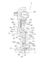
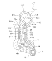
ロックアップ装置7は、フロントカバー2とタービン4との間に配置され、フロントカバー2からタービン4に動力を直接伝達するものである。このロックアップ装置7は、図2に拡大して示すように、クラッチディスク28と、プレッシャプレート29と、ピストン30と、ピストン作動機構31と、ダンパ機構34と、を有している。
[Lock-up device 7]
The
<クラッチディスク28>
クラッチディスク28は、環状に形成されており、フロントカバー2の摩擦面2bに圧接可能である。クラッチディスク28は、環状のコアプレート36と、コアプレート36の両側面に固定された環状の摩擦部材37と、を有している。コアプレート36の外周部は、摩擦部材37の外径よりも大きく、摩擦部材37から外周側に突出した部分がタービン側に所定の角度で折り曲げられている。そして、この折曲げ部分に、複数の係合突起36aが形成されている。
<
The
<プレッシャプレート29>
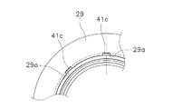
プレッシャプレート29は、クラッチディスク28とピストン30との間に軸方向に移動自在に配置されている。プレッシャプレート29は、ピストン30により押圧されて、クラッチディスク28をフロントカバー2側に押圧する。また、プレッシャプレート29は、環状に形成されており、外径はクラッチディスク28の摩擦部材37の外径よりも大きく、内径は摩擦部材37の内径より小さい。プレッシャプレート29の内周端部には、図3に拡大して示すように、円周方向に所定の間隔で複数の溝29aが形成されている。各溝29aは、径方向に所定の深さを有し、内周側が開口している。なお、図3はプレッシャプレート29をフロントカバー2側から視た図である。
<
The
<ピストン30>
ピストン30は、図1及び図2に示すように、フロントカバー2とタービン4との間に配置され、軸方向に移動自在である。ピストン30は、円板状の受圧部30aと、第1突出部30bと、第2突出部30cと、外周円板部30dと、を有している。なお、受圧部30aと外周円板部30dによって本体部が形成されている。
<
As shown in FIGS. 1 and 2, the
受圧部30aは作動油の圧力を受ける部分であり、第1突出部30bは受圧部30aの外周部に、タービン4側に突出して形成されている。受圧部30aの外周端部はフロントカバー2側に傾斜して延びており、第2突出部30cは、この傾斜して延びた部分の先端に、さらにフロントカバー2側に突出して形成されている。
The
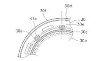
外周円板部30dは、受圧部30aと一体で、受圧部30aに対してフロントカバー側にオフセットされている。図4に示すように、外周円板部30dの内周部には、円周方向に所定の間隔で複数の開口30eが形成されている。複数の開口30eは軸方向に貫通している。なお、図4はピストン30をフロントカバー2側から視た図である。
The outer
また、外周円板部30dの外周端部には、環状の押圧部30fが形成されている。押圧部30fは、外周円板部30dの外周端部に、フロントカバー2側に突出して形成されている。この押圧部30fは、プレッシャプレート29の径方向の幅のほぼ中央部に当接するように形成されている。
An annular
<ピストン作動機構31>
ピストン30は、ピストン作動機構31によって軸方向に作動する。図2に示すように、ピストン作動機構31は、支持用ボス40と、カバープレート(油室プレート)41と、リターン機構42と、を有している。
<
The
−支持用ボス40−
支持用ボス40は、図2及び図5に示すように、フロントカバー2の内周部に固定されている。具体的には、支持用ボス40は、センタボス8の一部であり、センタボス8のタービン4側端部から軸方向に延びる筒状に形成されている。支持用ボス40は、第1固定部40aと、ピストン支持部40bと、第2固定部40cと、第1中間部40dと、第2中間部40eと、を有している。なお、図5は図1の拡大部分図である。
-Support boss 40-
The supporting
第1固定部40aは、外周面にフロントカバー2の内周端面が溶接により固定されている。すなわち、第1固定部40aの外周面にフロントカバー2の内周端面が挿入されて固定されていることにより、センタボス8及び支持用ボス40に対してフロントカバー2が芯出しされている。
As for the 1st fixing |
ピストン支持部40bは、外径が第1固定部40aの外径よりも大きく形成されている。ピストン支持部40bの外周面には、ピストン30の内周端面が軸方向に摺動自在に支持されている。また、ピストン支持部40bの外周面には、シール部材45が装着されている。このシール部材45によって、ピストン支持部40bの外周面とピストン30の内周端面との間がシールされている。なお、ピストン支持部40bのフロントカバー2側の側面は、外周側に行くにしたがってフロントカバー2側に近づくように傾斜している。
The
第2固定部40cは、外径がピストン支持部40bの外径よりも小さい。すなわち、ピストン支持部40bと第2固定部40cとは段違いになっている。この第2固定部40cの外周面に、カバープレート41の内周端面が溶接により固定されている。第2固定部40cの外径を、シール部材45が装着されたピストン支持部40bの外径よりも小さくすることによって、第2固定部40cにカバープレート41を溶接した際にも、溶接によるピストン支持部40bの歪を抑えることができる。したがって、ピストン支持部40bとピストン30との間のシール性が向上する。
The second fixed
第1中間部40dは、第1固定部40aとピストン支持部40bとの間に形成されている。第1中間部40dの外周面は、フロントカバー2側からタービン4側に向けて径が大きくなるように傾斜している。第1中間部40dの外周面の最小径は第1固定部40aの直径よりも大きく、最大径はピストン支持部40bの直径よりも小さい。
The first
第2中間部40eは、ピストン支持部40bと第2固定部40cとの間に形成されている。第2中間部40eの外周面は、フロントカバー2側からタービン4側に向けて径が小さくなるように傾斜している。第2中間部40eの外周面の最大径はピストン支持部40bの直径よりも小さく、最小径は第2固定部40cの直径よりも大きい。
The second
なお、支持用ボス40のタービン4側の端面とタービンハブ16との間には、スラストワッシャ46が配置されている。スラストワッシャ46の表面には、径方向に関する溝が形成されている。
A
−カバープレート41−
カバープレート41は、フロントカバー2との間にピストン30の受圧部30aを挟むように配置されている。カバープレート41は、図2に示すように、本体部41aと、シール部41bと、トルク伝達部41cと、を有している。
-Cover plate 41-
The
本体部41aは、円板状に形成されており、前述のように、内周端面が支持用ボス40の第2固定部40cの外周面に溶接によって固定されている。
The
シール部41bは、本体部41aの外周部に形成されており、タービン4側に窪む凹部41dを有している。この凹部41dに、ピストン30の第1突出部30bが挿入されている。第1突出部30bの外周部にはシール部材47が装着されており、シール部材47の外周部が凹部41dの内周面に当接している。したがって、このシール部材47によって、ピストン30とカバープレート41との間にロックアップ用油室C1が形成されている。
The
トルク伝達部41cは、シール部41bのさらに外周側に形成されている。トルク伝達部41cは、シール部41bの外周部からフロントカバー側に延びる複数の係合突起(以下、「係合突起41c」と記す)である。この係合突起41cは、図2及び図4に示すように、ピストン30に形成された開口30eを貫通し、プレッシャプレート29の内周端部に形成された溝29aに係合している。図6に、カバープレート41及びピストン30をタービン4側から視た斜視図を示している。
The
このような構成により、カバープレート41に伝達されたトルクを、プレッシャプレート29に伝達することが可能である。また、トルク伝達部としての係合突起41cの円周方向の寸法とピストン30の開口30eの円周方向の寸法とを適切に設定することによって、カバープレート41に対するピストン30の相対回転を規制することができる。
With such a configuration, the torque transmitted to the
リターン機構42は、フロントカバー2とピストン30との間に配置されており、ピストン30をフロントカバー2の摩擦面から離れる方向に付勢する機構である。また、リターン機構42は、ピストン30をフロントカバー2から離れる方向に付勢するとともに、フロントカバー2の摩擦面2bとピストン30の押圧部30fとの間の隙間を調整する機能を有している。
The
具体的には、雰囲気温度が低温の場合は、ピストン30をフロントカバー2から離れるように移動させ、ピストン30とフロントカバー2との間の隙間、すなわち、クラッチディスク28が設けられた部分の隙間(クラッチディスク28の切れ代)を大きくする。したがって、クラッチディスク28部分におけるドラグトルクを小さく抑えることができる。
Specifically, when the ambient temperature is low, the
一方、雰囲気温度が高くなって、例えば常温になると、ピストン30をフロントカバー2に近づくように移動させる。このため、ピストン30とフロントカバー2との間の隙間、すなわち、クラッチディスク28が設けられた部分の隙間(クラッチディスク28の切れ代)が小さくなる。したがって、素早くロックアップさせることができる。
On the other hand, when the ambient temperature becomes high, for example, at room temperature, the
<油圧回路>
ピストン作動機構31の構成によって、図2に示すように、ピストン30の受圧部30aとカバープレート41の本体部41aとの間には、ロックアップ用油室C1が形成されている。また、フロントカバー2の径方向中間部と内周部との間には、軸方向に延びる筒状の段付き部2cが形成されており、この段付き部2cの外周面には、シール部材57が装着されている。シール部材57は、ピストン30の第2突出部30cの内周面に当接している。したがって、ピストン30の受圧部30aとフロントカバー2との間には、ロックアップオフ時にロックアップ用油室C1で発生する油圧をキャンセルするためのキャンセル用油室C2が形成されている。
<Hydraulic circuit>
Due to the configuration of the
なお、フロントカバー2の段付き部2cに装着されたシール部材57は、通常のシール部材(例えば第1突出部30bに装着されたシール部材47)よりもシール性能が劣る。具体的には、シール部材57を段付き部2cに装着した状態でも、シール部材57の突き合わせ部の隙間が、通常設定されている隙間よりも広くなるように設定されている。このため、シール部材57が装着された部分では、他のシール部に比較して作動油の漏れ量が多くなる。これにより、キャンセル用油室C2に作動油が供給され、キャンセル用油室C2は所望の圧力に設定される。
The
支持用ボス40には、図2及び図5に示すように、径方向に貫通する第1油路P1及び第2油路P2が形成されている。第1油路P1は、支持用ボス40の第2中間部40eの傾斜面に開口し、ロックアップ用油室C1と支持用ボス40の内周部の空間とを連通する。第2油路P2は、第1中間部40dの傾斜面に開口し、キャンセル用油室C2と支持用ボス40の内周部の空間とを連通する。カラー18には、環状の溝18aが形成されており、この溝18aに、径方向に貫通する複数の第3油路P3が形成されている。そして、第2油路P2は第3油路P3と連通している。
As shown in FIGS. 2 and 5, the
また、図1に示すように、第3油路P3は、トランスミッションの入力軸(図示せず)の内部を貫通する第4油路P4に連通している。この第4油路P4はトランスミッションのドレンタンクTに連通している。第4油路P4の途中には、キャンセル用油室C2の内部圧力を所定の圧力に維持するための油圧維持回路(キャンセル油圧維持回路)58が設けられている。 Further, as shown in FIG. 1, the third oil passage P3 communicates with a fourth oil passage P4 that penetrates the inside of the input shaft (not shown) of the transmission. The fourth oil passage P4 communicates with a drain tank T of the transmission. A hydraulic pressure maintenance circuit (cancellation hydraulic pressure maintenance circuit) 58 for maintaining the internal pressure of the cancellation oil chamber C2 at a predetermined pressure is provided in the middle of the fourth oil passage P4.
油圧維持回路58は、第4油路P4の出口部分に形成された絞り58aと、第4油路P4に連絡油路P5を介して接続された油圧供給源58bと、を有している。絞り58aは、第4油路P4の一部を小径に絞ったオリフィス等の作動油の流れに抵抗を与える構成であればよい。油圧供給源58bは、油圧ポンプや圧力制御弁等を含み、油路P2,P3,P4及びキャンセル用油室C2が所定の圧力に維持されるように構成されている。
The hydraulic
<ダンパ機構34>
ダンパ機構34は、クラッチディスク28とタービン4との間に配置され、クラッチディスク28からのトルクをタービン4に伝達するものである。図7に示すように、ダンパ機構34は、係合部材60と、ドライブプレート61と、ドリブンプレート62と、複数のトーションスプリング63と、を有している。
<
The
係合部材60は、固定部60aと、それぞれ複数の第1係合部60b及び第2係合部60cと、を有している。固定部60aは、環状に形成され、リベット65によってドライブプレート61に固定されている。複数の第1係合部60bは、固定部60aの外周端をフロントカバー2側に折り曲げて形成されており、クラッチディスク28のコアプレート36の外周に形成された係合突起36aに噛み合っている。クラッチディスク28は、第1係合部60bに対して、軸方向には移動自在であり、相対回転は禁止されている。複数の第2係合部60cは、固定部60aの外周端をタービン4側に折り曲げて形成されている。
The engaging
ドライブプレート61は、環状に形成されており、ピストン30とタービン4との間に配置されている。ドライブプレート61は、係合部材60に伝達されたトルクをトーションスプリング63に伝達する。ドライブプレート61は、円板部61aと、複数の支持部61bと、複数の係合部61cと、を有している。
The
円板部61aの内周端面は、タービン4側に折り曲げられて、位置決め部61dとなっている。この位置決め部61dが、タービンハブ16の外周端部に形成されたダンパ支持部16cによって、支持され、径方向及び軸方向に位置決めされている。円板部61aの外周部には、軸方向に貫通する孔61eが形成されている。この孔61eを、係合部材60の第2係合部60cが貫通し、タービン4側に延びている。
The inner peripheral end surface of the
支持部61bは、円板部61aの外周部に形成され、断面C字状である。この支持部61bに、複数のトーションスプリング63が収容されており、支持部61bによって、トーションスプリング63の径方向及びフロントカバー2側への移動が規制されている。
The
係合部61cは、円板部61aの外周部において、隣接する支持部61bの間に形成されている。係合部61cの一部が、支持部61bに収容されたトーションスプリング63の両端面に係合している。
The engaging
ドリブンプレート62は、概略円板状に形成されており、ドライブプレート61とタービン4との間に配置されている。ドリブンプレート62は、トーションスプリング63に伝達されたトルクをタービンハブ16に伝達するものである。ドリブンプレート62は、内周端部がリベット17によってタービンシェル14及びタービンハブ16に固定されている。また、ドリブンプレート62は、タービンシェル14の側面に沿って外周側に延びており、外周部に形成された係合部62aがトーションスプリング63の両端面に係合している。
The driven
[動作]
ロックアップ装置7において、ロックアップを解除(クラッチオフ=ロックアップオフ)する場合には、ロックアップ用油室C1はドレンに接続される。したがって、ロックアップ用油室C1内の作動油は、第1油路P1を介してタンクT側に戻される。このような状態では、ピストン30は、リターン機構42によってタービン4側に移動し、ピストン30の押圧部30fによるプレッシャプレート29への押圧力が解除される。したがって、ロックアップオフ(動力伝達が解除された状態)であり、フロントカバー2からのトルクは、作動油を介してインペラ3からタービン4に伝達され、タービンハブ16を介してトランスミッションの入力シャフトに伝達される。
[Operation]
When the
なお、このロックアップオフのときに、ロックアップ用油室C1に残った作動油に遠心力が作用し、これによってピストン30がフロントカバー2側に押される場合がある。ピストン30がフロントカバー2側に移動すると、クラッチディスク28によるドラグトルクが大きくなる。
When the lock-up is off, centrifugal force may act on the hydraulic oil remaining in the lock-up oil chamber C1, which may push the
そこで、この装置では、前述のように、シール部材57からの漏れ量が、通常の漏れ量より多くなるようにしている。このため、シール部材57から漏れた作動油がキャンセル用油室C2に侵入し、ピストン30のフロントカバー2側への移動を抑えている。すなわち、ロックアップ用油室C1における作動油の遠心力によって作用するピストン30への押圧力を、シール部材57からキャンセル用油室C2に漏れる作動油によってキャンセルするようにしている。キャンセル用油室C2では、シール部材57から侵入する作動油によって、また油圧維持回路58の作用によって、所定の油圧に維持される。
Therefore, in this apparatus, as described above, the leakage amount from the
なお、シール部材57の隙間が異物等によって詰まった場合、キャンセル用油室C2にはシール部材57を介して作動油が侵入しなくなる。しかし、このような場合であっても、油圧維持回路58によって、第2〜第4油路P2,P3,P4及びキャンセル用油室C2の油圧は、所定の油圧に維持される。
When the gap between the
一方、ロックアップ装置7において、ロックアップオン(クラッチオン=動力伝達状態)にする場合は、ロックアップ用油室C1に作動油を供給する。すなわち、カラー18の端面に作動油を供給するとともに、第1油路P1を介して、作動油をロックアップ用油室C1に供給する。これにより、ピストン30はフロントカバー2側に移動し、プレッシャプレート29をフロントカバー2側に移動させる。このため、クラッチディスク28がフロントカバー2とプレッシャプレート29との間に挟持され、ロックアップオンの状態になる。
On the other hand, in the
ロックアップオンの状態では、フロントカバー2からのトルクは、支持用ボス40→カバープレート41→プレッシャプレート29→クラッチディスク28の経路を介して、またフロントカバー2からクラッチディスク28を介してダンパ機構34に伝達される。
In the lock-up-on state, the torque from the
また、このロックアップオン状態の場合にも、シール部材57を介してキャンセル用油室C2には作動油が侵入する。このため、前述のように、キャンセル用油室C2は所定の油圧になり、トルクコンバータ本体6の内圧の変動によるロックアップクラッチの締結力の変動を抑制することができる。
Even in the lock-up on state, the hydraulic oil enters the canceling oil chamber C <b> 2 through the
なお、シール部材57が異物等によって詰まった場合であっても、前記同様に、油圧維持回路58によってキャンセル用油室C2の圧力を所定の圧力に維持することができる。
Even when the
ダンパ機構34においては、係合部材60に入力されたトルクは、トーションスプリング63及びドリブンプレート62を介してタービン4に伝達され、さらにタービンハブ16を介してトランスミッションの入力シャフトに伝達される。
In the
[他の実施形態]
本発明は以上のような実施形態に限定されるものではなく、本発明の範囲を逸脱することなく種々の変形又は修正が可能である。
[Other Embodiments]
The present invention is not limited to the above-described embodiments, and various changes or modifications can be made without departing from the scope of the present invention.
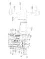
(a)他の実施形態による油圧維持回路58’を図8に示している。ここでは、前記実施形態の第4油路P4に代わり、第4油路P40が設けられている。第4油路P40は、第3油路P3に連通し、かつトランスミッションの入力軸(図示せず)の内部に設けられている。第4油路P40は、トランスミッションのドレンタンクTに連通しており、その一部に上部油路P40aを有している。上部油路P40aは、トルクコンバータ1の回転軸O−Oより上方に位置するように配置されている。
(A) FIG. 8 shows a hydraulic
なお、油圧維持回路58’の他の構成は前記実施形態と同様である。すなわち、油圧維持回路58’は、第4油路P40の出口部分に形成された絞り58aと、第4油路P40に連絡油路P5を介して接続された油圧供給源58bと、を有している。絞り58aは、第4油路P40の一部を小径に絞ったオリフィス等の作動油の流れに抵抗を与える構成であればよい。油圧供給源58bは、油圧ポンプや圧力制御弁等を含み、油路P2,P3,P40及びキャンセル用油室C2が所定の圧力に維持されるように構成されている。
Other configurations of the hydraulic pressure maintaining circuit 58 'are the same as those in the above embodiment. That is, the hydraulic
このような実施形態においても、前記実施形態と同様の作用効果を得ることができる。 Also in such an embodiment, the same operational effects as in the above embodiment can be obtained.
(b)ロックアップ用油室及びキャンセル用油室の配置や、これらの油室に連通する油路の配置は、前記実施形態に限定されず、前記実施形態とは軸方向において逆に配置されていてもよい。 (B) The arrangement of the lockup oil chamber and the cancellation oil chamber, and the arrangement of the oil passages communicating with these oil chambers are not limited to the above-described embodiment, and are arranged opposite to the above-described embodiment in the axial direction. It may be.
2 フロントカバー
2b 摩擦面
28 クラッチディスク
30 ピストン
40 支持用ボス
41 カバープレート(油室プレート)
58,58’ 油圧維持回路
58a オリフィス(絞り)
C1 ロックアップ用油室
C2 キャンセル用油室
P1 第1油路
P2 第2油路
P3 第3油路
P4,P40 第4油路
P40a 上部油路
2
58, 58 'Oil
C1 Lock-up oil chamber C2 Cancel oil chamber P1 First oil passage P2 Second oil passage P3 Third oil passage P4, P40 Fourth oil passage P40a Upper oil passage
Claims (5)
前記フロントカバーと前記トランスミッション側の部材との動力伝達経路に配置されたクラッチ部と、
軸方向に移動自在に設けられたピストンと、
前記ピストンを移動させて前記クラッチ部を動力伝達状態にするための作動油が供給されるロックアップ用油室と、
前記ピストンを挟んで前記ロックアップ用油室と反対側に設けられ、作動油が供給されるキャンセル用油室と、
前記キャンセル用油室から排出された作動油を前記トランスミッション側に導く油路に設けられ、前記キャンセル用油室を所定の油圧に維持するキャンセル油圧維持回路と、
前記キャンセル用油室の外周部に設けられた第1シール部材と、
前記キャンセル用油室の内周部に設けられた第2シール部材と、
を備え、
前記キャンセル用油室には前記第1シール部材の隙間を介して作動油が供給される、
トルクコンバータのロックアップ装置。 A torque converter lockup device for transmitting torque input to a front cover to a member on a transmission side,
A clutch portion disposed in a power transmission path between the front cover and the transmission-side member;
A piston provided so as to be movable in the axial direction;
A lockup oil chamber to which hydraulic oil for moving the piston to bring the clutch portion into a power transmission state is supplied;
A canceling oil chamber provided on the opposite side of the lockup oil chamber across the piston, to which hydraulic oil is supplied;
A cancel oil pressure maintaining circuit that is provided in an oil passage that guides hydraulic oil discharged from the cancel oil chamber to the transmission side, and maintains the cancel oil chamber at a predetermined oil pressure;
A first seal member provided on the outer periphery of the cancellation oil chamber;
A second seal member provided on the inner periphery of the canceling oil chamber;
With
Hydraulic oil is supplied to the cancellation oil chamber through the gap of the first seal member.
Torque converter lockup device.
前記支持用ボスの外周面に、前記フロントカバーとの間に前記ピストンを挟むように固定され、前記ピストンとの間に前記ロックアップ用油室を構成する円板状の油室プレートと、
をさらに備えた、請求項1に記載のトルクコンバータのロックアップ装置。 An annular support boss, which is axially projected and fixed to the inner peripheral portion of the front cover, and the piston is slidably supported on the outer peripheral surface in the axial direction;
A disk-like oil chamber plate that is fixed to the outer peripheral surface of the supporting boss so as to sandwich the piston between the front cover and that constitutes the lock-up oil chamber between the piston and the piston;
Further comprising a torque converter lock-up device according to claim 1.
前記支持用ボスには、前記ロックアップ用油室及び前記キャンセル用油室のそれぞれに連通する油路が形成されている、
請求項2に記載のトルクコンバータのロックアップ装置。 The cancellation oil chamber is disposed between the front cover and the piston;
The supporting boss is formed with an oil passage communicating with each of the lockup oil chamber and the cancellation oil chamber.
The lockup device for a torque converter according to claim 2 .
The cancel hydraulic pressure maintaining circuit has an upper oil passage positioned above the rotation shaft of the torque converter, and the upper oil passage is an oil passage for guiding hydraulic oil discharged from the cancel oil chamber to the transmission side. The torque converter lockup device according to claim 4 , which is provided in a part.
Priority Applications (5)
| Application Number | Priority Date | Filing Date | Title |
|---|---|---|---|
| CN201680046926.1A CN107923505A (en) | 2015-08-19 | 2016-07-20 | The locking device of fluid torque-converter |
| KR1020177036369A KR20180042161A (en) | 2015-08-19 | 2016-07-20 | Lockup device of torque converter |
| DE112016002688.9T DE112016002688T5 (en) | 2015-08-19 | 2016-07-20 | Lock-up device for a torque converter |
| US15/576,753 US20180163837A1 (en) | 2015-08-19 | 2016-07-20 | Lock-up device for torque converter |
| PCT/JP2016/071238 WO2017029927A1 (en) | 2015-08-19 | 2016-07-20 | Lock-up apparatus for torque converter |
Applications Claiming Priority (2)
| Application Number | Priority Date | Filing Date | Title |
|---|---|---|---|
| JP2015161941 | 2015-08-19 | ||
| JP2015161941 | 2015-08-19 |
Publications (3)
| Publication Number | Publication Date |
|---|---|
| JP2017040361A JP2017040361A (en) | 2017-02-23 |
| JP2017040361A5 JP2017040361A5 (en) | 2019-02-14 |
| JP6608317B2 true JP6608317B2 (en) | 2019-11-20 |
Family
ID=58206539
Family Applications (1)
| Application Number | Title | Priority Date | Filing Date |
|---|---|---|---|
| JP2016059035A Active JP6608317B2 (en) | 2015-08-19 | 2016-03-23 | Torque converter lockup device |
Country Status (5)
| Country | Link |
|---|---|
| US (1) | US20180163837A1 (en) |
| JP (1) | JP6608317B2 (en) |
| KR (1) | KR20180042161A (en) |
| CN (1) | CN107923505A (en) |
| DE (1) | DE112016002688T5 (en) |
Families Citing this family (7)
| Publication number | Priority date | Publication date | Assignee | Title |
|---|---|---|---|---|
| JP7043312B2 (en) * | 2018-03-28 | 2022-03-29 | 株式会社エクセディ | Vehicle drive |
| US11187312B2 (en) * | 2019-06-13 | 2021-11-30 | Schaeffler Technologies AG & Co. KG | Torque converter with stacked plate four-pass clutch |
| CN110985663B (en) * | 2020-02-27 | 2020-07-14 | 盛瑞传动股份有限公司 | Hydraulic torque converter control system, transmission and automobile |
| JP7477370B2 (en) * | 2020-06-01 | 2024-05-01 | 株式会社エクセディ | Lock-up Device |
| US12270447B2 (en) * | 2021-11-18 | 2025-04-08 | Schaeffler Technologies AG & Co. KG | Vibration damper with intermediate flange travel stop and torque converter with vibration damper having intermediate flange travel stop |
| US11592091B1 (en) * | 2022-02-09 | 2023-02-28 | Schaeffler Technologies AG & Co. KG | Torque converter assembly including thrust washer |
| CN114934989A (en) * | 2022-05-10 | 2022-08-23 | 陕西航天动力高科技股份有限公司 | Hydraulic torque converter with high locking performance |
Family Cites Families (10)
| Publication number | Priority date | Publication date | Assignee | Title |
|---|---|---|---|---|
| JPS58180870A (en) * | 1982-04-16 | 1983-10-22 | Aisin Warner Ltd | Direct coupled clutch controlling mechanism for automatic automotive speed change gear |
| DE19508613A1 (en) * | 1995-03-10 | 1996-09-12 | Fichtel & Sachs Ag | Hydrodynamic torque converter with pump impeller driven by IC engine |
| US6367605B1 (en) * | 1998-07-20 | 2002-04-09 | Luk Getriebe-Systeme Gmbh | Hydrokinetic torque converter with lockup clutch |
| JP2005282617A (en) * | 2004-03-26 | 2005-10-13 | Aisin Seiki Co Ltd | Torque converter with lock-up clutch |
| DE102004060257A1 (en) * | 2004-12-15 | 2006-07-06 | Zf Friedrichshafen Ag | Hydrodynamic coupling device |
| JP5202718B1 (en) * | 2011-12-05 | 2013-06-05 | 株式会社エクセディ | Torque converter lockup device |
| JP5584249B2 (en) * | 2012-04-10 | 2014-09-03 | 株式会社エクセディ | Torque converter lockup device |
| KR20140030762A (en) * | 2012-09-03 | 2014-03-12 | 현대자동차주식회사 | A hydraulic control apparatus for hydraulic torque converter |
| JP5998896B2 (en) * | 2012-12-10 | 2016-09-28 | マツダ株式会社 | Automatic transmission |
| JP5878893B2 (en) * | 2013-07-11 | 2016-03-08 | 株式会社エクセディ | Torque converter lockup device |
-
2016
- 2016-03-23 JP JP2016059035A patent/JP6608317B2/en active Active
- 2016-07-20 US US15/576,753 patent/US20180163837A1/en not_active Abandoned
- 2016-07-20 DE DE112016002688.9T patent/DE112016002688T5/en not_active Withdrawn
- 2016-07-20 KR KR1020177036369A patent/KR20180042161A/en not_active Withdrawn
- 2016-07-20 CN CN201680046926.1A patent/CN107923505A/en active Pending
Also Published As
| Publication number | Publication date |
|---|---|
| JP2017040361A (en) | 2017-02-23 |
| DE112016002688T5 (en) | 2018-03-08 |
| US20180163837A1 (en) | 2018-06-14 |
| CN107923505A (en) | 2018-04-17 |
| KR20180042161A (en) | 2018-04-25 |
Similar Documents
| Publication | Publication Date | Title |
|---|---|---|
| JP6608317B2 (en) | Torque converter lockup device | |
| JP2017040361A5 (en) | ||
| JP5401821B2 (en) | Starting device | |
| CN104204616B (en) | Locking device for torque converter | |
| WO2013084637A1 (en) | Lockup device for torque converter | |
| JP2005282617A (en) | Torque converter with lock-up clutch | |
| CN103958936A (en) | Lockup device for torque converter | |
| WO2013084636A1 (en) | Lockup device for torque converter | |
| KR102327513B1 (en) | Lock-up device for torque converter | |
| JP6173814B2 (en) | clutch | |
| US8042666B2 (en) | Hydrodynamic clutch device | |
| JP6639807B2 (en) | Lockup device for torque converter | |
| WO2016186125A1 (en) | Torque converter lock-up device | |
| WO2017029927A1 (en) | Lock-up apparatus for torque converter | |
| JP5012808B2 (en) | Fluid transmission device | |
| JP6328184B2 (en) | Transmission unit | |
| JP2016217447A (en) | Lock-up device of torque converter | |
| JP6779083B2 (en) | Torque converter | |
| JP6473044B2 (en) | Torque converter lockup device | |
| JP2018028338A (en) | Torque converter | |
| JP2016217446A (en) | Torque converter lockup device | |
| JP2021071124A (en) | Starting device | |
| WO2016163172A1 (en) | Fluid coupling | |
| JP4265469B2 (en) | Fluid transmission device with lock-up clutch | |
| JP2018028339A (en) | Torque converter |
Legal Events
| Date | Code | Title | Description |
|---|---|---|---|
| A621 | Written request for application examination |
Free format text: JAPANESE INTERMEDIATE CODE: A621 Effective date: 20181221 |
|
| A521 | Request for written amendment filed |
Free format text: JAPANESE INTERMEDIATE CODE: A523 Effective date: 20181226 |
|
| A131 | Notification of reasons for refusal |
Free format text: JAPANESE INTERMEDIATE CODE: A131 Effective date: 20190806 |
|
| A521 | Request for written amendment filed |
Free format text: JAPANESE INTERMEDIATE CODE: A523 Effective date: 20190920 |
|
| TRDD | Decision of grant or rejection written | ||
| A01 | Written decision to grant a patent or to grant a registration (utility model) |
Free format text: JAPANESE INTERMEDIATE CODE: A01 Effective date: 20191008 |
|
| A61 | First payment of annual fees (during grant procedure) |
Free format text: JAPANESE INTERMEDIATE CODE: A61 Effective date: 20191023 |
|
| R150 | Certificate of patent or registration of utility model |
Ref document number: 6608317 Country of ref document: JP Free format text: JAPANESE INTERMEDIATE CODE: R150 |
|
| R250 | Receipt of annual fees |
Free format text: JAPANESE INTERMEDIATE CODE: R250 |
|
| R250 | Receipt of annual fees |
Free format text: JAPANESE INTERMEDIATE CODE: R250 |