KR20180023195A - Smart sunlight security street light system - Google Patents
Smart sunlight security street light system Download PDFInfo
- Publication number
- KR20180023195A KR20180023195A KR1020160108103A KR20160108103A KR20180023195A KR 20180023195 A KR20180023195 A KR 20180023195A KR 1020160108103 A KR1020160108103 A KR 1020160108103A KR 20160108103 A KR20160108103 A KR 20160108103A KR 20180023195 A KR20180023195 A KR 20180023195A
- Authority
- KR
- South Korea
- Prior art keywords
- image
- post
- branch
- solar panel
- unit
- Prior art date
Links
- 238000004146 energy storage Methods 0.000 claims abstract description 15
- 230000001815 facial effect Effects 0.000 claims abstract description 7
- 238000003384 imaging method Methods 0.000 claims description 14
- 239000000779 smoke Substances 0.000 claims description 13
- 238000004891 communication Methods 0.000 claims description 10
- 230000033001 locomotion Effects 0.000 claims description 9
- 238000000034 method Methods 0.000 claims description 9
- 238000005259 measurement Methods 0.000 claims description 5
- 230000008878 coupling Effects 0.000 description 7
- 238000010168 coupling process Methods 0.000 description 7
- 238000005859 coupling reaction Methods 0.000 description 7
- 238000001514 detection method Methods 0.000 description 5
- 238000010248 power generation Methods 0.000 description 5
- 230000007613 environmental effect Effects 0.000 description 3
- 238000004519 manufacturing process Methods 0.000 description 3
- 241001465754 Metazoa Species 0.000 description 2
- 230000008859 change Effects 0.000 description 2
- 238000010586 diagram Methods 0.000 description 2
- 230000005611 electricity Effects 0.000 description 2
- 238000009434 installation Methods 0.000 description 2
- 238000012986 modification Methods 0.000 description 2
- 230000004048 modification Effects 0.000 description 2
- WHXSMMKQMYFTQS-UHFFFAOYSA-N Lithium Chemical compound [Li] WHXSMMKQMYFTQS-UHFFFAOYSA-N 0.000 description 1
- BNOODXBBXFZASF-UHFFFAOYSA-N [Na].[S] Chemical compound [Na].[S] BNOODXBBXFZASF-UHFFFAOYSA-N 0.000 description 1
- 238000013459 approach Methods 0.000 description 1
- 230000008901 benefit Effects 0.000 description 1
- 230000005540 biological transmission Effects 0.000 description 1
- 230000004397 blinking Effects 0.000 description 1
- 239000003990 capacitor Substances 0.000 description 1
- 230000003203 everyday effect Effects 0.000 description 1
- 238000007667 floating Methods 0.000 description 1
- 238000005286 illumination Methods 0.000 description 1
- 229910052744 lithium Inorganic materials 0.000 description 1
- 239000011159 matrix material Substances 0.000 description 1
- 230000002093 peripheral effect Effects 0.000 description 1
- 238000004321 preservation Methods 0.000 description 1
- 230000002265 prevention Effects 0.000 description 1
- 238000012545 processing Methods 0.000 description 1
- 230000001131 transforming effect Effects 0.000 description 1
- 230000003442 weekly effect Effects 0.000 description 1
Images

Classifications
-
- F—MECHANICAL ENGINEERING; LIGHTING; HEATING; WEAPONS; BLASTING
- F21—LIGHTING
- F21S—NON-PORTABLE LIGHTING DEVICES; SYSTEMS THEREOF; VEHICLE LIGHTING DEVICES SPECIALLY ADAPTED FOR VEHICLE EXTERIORS
- F21S8/00—Lighting devices intended for fixed installation
- F21S8/08—Lighting devices intended for fixed installation with a standard
- F21S8/085—Lighting devices intended for fixed installation with a standard of high-built type, e.g. street light
-
- F—MECHANICAL ENGINEERING; LIGHTING; HEATING; WEAPONS; BLASTING
- F21—LIGHTING
- F21S—NON-PORTABLE LIGHTING DEVICES; SYSTEMS THEREOF; VEHICLE LIGHTING DEVICES SPECIALLY ADAPTED FOR VEHICLE EXTERIORS
- F21S9/00—Lighting devices with a built-in power supply; Systems employing lighting devices with a built-in power supply
- F21S9/02—Lighting devices with a built-in power supply; Systems employing lighting devices with a built-in power supply the power supply being a battery or accumulator
- F21S9/03—Lighting devices with a built-in power supply; Systems employing lighting devices with a built-in power supply the power supply being a battery or accumulator rechargeable by exposure to light
-
- F—MECHANICAL ENGINEERING; LIGHTING; HEATING; WEAPONS; BLASTING
- F21—LIGHTING
- F21V—FUNCTIONAL FEATURES OR DETAILS OF LIGHTING DEVICES OR SYSTEMS THEREOF; STRUCTURAL COMBINATIONS OF LIGHTING DEVICES WITH OTHER ARTICLES, NOT OTHERWISE PROVIDED FOR
- F21V23/00—Arrangement of electric circuit elements in or on lighting devices
- F21V23/04—Arrangement of electric circuit elements in or on lighting devices the elements being switches
- F21V23/0442—Arrangement of electric circuit elements in or on lighting devices the elements being switches activated by means of a sensor, e.g. motion or photodetectors
-
- F—MECHANICAL ENGINEERING; LIGHTING; HEATING; WEAPONS; BLASTING
- F21—LIGHTING
- F21V—FUNCTIONAL FEATURES OR DETAILS OF LIGHTING DEVICES OR SYSTEMS THEREOF; STRUCTURAL COMBINATIONS OF LIGHTING DEVICES WITH OTHER ARTICLES, NOT OTHERWISE PROVIDED FOR
- F21V33/00—Structural combinations of lighting devices with other articles, not otherwise provided for
- F21V33/0004—Personal or domestic articles
- F21V33/0052—Audio or video equipment, e.g. televisions, telephones, cameras or computers; Remote control devices therefor
-
- F—MECHANICAL ENGINEERING; LIGHTING; HEATING; WEAPONS; BLASTING
- F21—LIGHTING
- F21V—FUNCTIONAL FEATURES OR DETAILS OF LIGHTING DEVICES OR SYSTEMS THEREOF; STRUCTURAL COMBINATIONS OF LIGHTING DEVICES WITH OTHER ARTICLES, NOT OTHERWISE PROVIDED FOR
- F21V33/00—Structural combinations of lighting devices with other articles, not otherwise provided for
- F21V33/0064—Health, life-saving or fire-fighting equipment
- F21V33/0076—Safety or security signalisation, e.g. smoke or burglar alarms, earthquake detectors; Self-defence devices
-
- G—PHYSICS
- G08—SIGNALLING
- G08B—SIGNALLING OR CALLING SYSTEMS; ORDER TELEGRAPHS; ALARM SYSTEMS
- G08B25/00—Alarm systems in which the location of the alarm condition is signalled to a central station, e.g. fire or police telegraphic systems
- G08B25/14—Central alarm receiver or annunciator arrangements
-
- G—PHYSICS
- G08—SIGNALLING
- G08B—SIGNALLING OR CALLING SYSTEMS; ORDER TELEGRAPHS; ALARM SYSTEMS
- G08B5/00—Visible signalling systems, e.g. personal calling systems, remote indication of seats occupied
- G08B5/22—Visible signalling systems, e.g. personal calling systems, remote indication of seats occupied using electric transmission; using electromagnetic transmission
- G08B5/36—Visible signalling systems, e.g. personal calling systems, remote indication of seats occupied using electric transmission; using electromagnetic transmission using visible light sources
-
- H—ELECTRICITY
- H02—GENERATION; CONVERSION OR DISTRIBUTION OF ELECTRIC POWER
- H02S—GENERATION OF ELECTRIC POWER BY CONVERSION OF INFRARED RADIATION, VISIBLE LIGHT OR ULTRAVIOLET LIGHT, e.g. USING PHOTOVOLTAIC [PV] MODULES
- H02S20/00—Supporting structures for PV modules
- H02S20/30—Supporting structures being movable or adjustable, e.g. for angle adjustment
-
- H—ELECTRICITY
- H02—GENERATION; CONVERSION OR DISTRIBUTION OF ELECTRIC POWER
- H02S—GENERATION OF ELECTRIC POWER BY CONVERSION OF INFRARED RADIATION, VISIBLE LIGHT OR ULTRAVIOLET LIGHT, e.g. USING PHOTOVOLTAIC [PV] MODULES
- H02S40/00—Components or accessories in combination with PV modules, not provided for in groups H02S10/00 - H02S30/00
- H02S40/30—Electrical components
- H02S40/38—Energy storage means, e.g. batteries, structurally associated with PV modules
-
- F—MECHANICAL ENGINEERING; LIGHTING; HEATING; WEAPONS; BLASTING
- F21—LIGHTING
- F21W—INDEXING SCHEME ASSOCIATED WITH SUBCLASSES F21K, F21L, F21S and F21V, RELATING TO USES OR APPLICATIONS OF LIGHTING DEVICES OR SYSTEMS
- F21W2131/00—Use or application of lighting devices or systems not provided for in codes F21W2102/00-F21W2121/00
- F21W2131/10—Outdoor lighting
- F21W2131/103—Outdoor lighting of streets or roads
-
- Y—GENERAL TAGGING OF NEW TECHNOLOGICAL DEVELOPMENTS; GENERAL TAGGING OF CROSS-SECTIONAL TECHNOLOGIES SPANNING OVER SEVERAL SECTIONS OF THE IPC; TECHNICAL SUBJECTS COVERED BY FORMER USPC CROSS-REFERENCE ART COLLECTIONS [XRACs] AND DIGESTS
- Y02—TECHNOLOGIES OR APPLICATIONS FOR MITIGATION OR ADAPTATION AGAINST CLIMATE CHANGE
- Y02B—CLIMATE CHANGE MITIGATION TECHNOLOGIES RELATED TO BUILDINGS, e.g. HOUSING, HOUSE APPLIANCES OR RELATED END-USER APPLICATIONS
- Y02B20/00—Energy efficient lighting technologies, e.g. halogen lamps or gas discharge lamps
- Y02B20/72—Energy efficient lighting technologies, e.g. halogen lamps or gas discharge lamps in street lighting
-
- Y—GENERAL TAGGING OF NEW TECHNOLOGICAL DEVELOPMENTS; GENERAL TAGGING OF CROSS-SECTIONAL TECHNOLOGIES SPANNING OVER SEVERAL SECTIONS OF THE IPC; TECHNICAL SUBJECTS COVERED BY FORMER USPC CROSS-REFERENCE ART COLLECTIONS [XRACs] AND DIGESTS
- Y02—TECHNOLOGIES OR APPLICATIONS FOR MITIGATION OR ADAPTATION AGAINST CLIMATE CHANGE
- Y02E—REDUCTION OF GREENHOUSE GAS [GHG] EMISSIONS, RELATED TO ENERGY GENERATION, TRANSMISSION OR DISTRIBUTION
- Y02E10/00—Energy generation through renewable energy sources
- Y02E10/50—Photovoltaic [PV] energy
-
- Y—GENERAL TAGGING OF NEW TECHNOLOGICAL DEVELOPMENTS; GENERAL TAGGING OF CROSS-SECTIONAL TECHNOLOGIES SPANNING OVER SEVERAL SECTIONS OF THE IPC; TECHNICAL SUBJECTS COVERED BY FORMER USPC CROSS-REFERENCE ART COLLECTIONS [XRACs] AND DIGESTS
- Y02—TECHNOLOGIES OR APPLICATIONS FOR MITIGATION OR ADAPTATION AGAINST CLIMATE CHANGE
- Y02E—REDUCTION OF GREENHOUSE GAS [GHG] EMISSIONS, RELATED TO ENERGY GENERATION, TRANSMISSION OR DISTRIBUTION
- Y02E70/00—Other energy conversion or management systems reducing GHG emissions
- Y02E70/30—Systems combining energy storage with energy generation of non-fossil origin
Landscapes
- Engineering & Computer Science (AREA)
- General Engineering & Computer Science (AREA)
- Physics & Mathematics (AREA)
- General Physics & Mathematics (AREA)
- Electromagnetism (AREA)
- Computer Security & Cryptography (AREA)
- Environmental & Geological Engineering (AREA)
- Multimedia (AREA)
- Business, Economics & Management (AREA)
- Emergency Management (AREA)
- Circuit Arrangement For Electric Light Sources In General (AREA)
Abstract
Description
본 발명은 태양광 보안 가로등 시스템에 관한 것으로, 보다 상세하게는 영상 촬영 및 인식 기능, 상황 전파 기능, 측위 기능, 기상측정 기능 등 다양한 기능을 수행할 수 있는 스마트 태양광 보안 가로등 시스템에 관한 것이다.The present invention relates to a solar street light streetlight system, and more particularly, to a smart street light streetlight system capable of performing various functions such as image shooting and recognition, a situation propagation function, a positioning function, a weather measurement function and the like.
가로등은 도로나 인도에 소정 높이로 설치되어 야간에 빛을 발함으로써 사람이나 차량 운전자가 시야를 확보할 수 있도록 하여 이들 사람이나 차량 운전자가 안전하고 편하게 이동할 수 있게 하는 대표적 수단이다. The streetlight is installed at a predetermined height on a road or a ledge so that a person or a vehicle driver can secure a vision by emitting light at night, thereby making it possible for the person or the vehicle driver to move safely and comfortably.
이러한 가로등은 전국 어디에서든 흔히 볼 수 있으며, 공원, 등산로, 산책로, 버스정류장, 산간 도서지역 주요 통행로, 전원주택단지, 생태보전지역, 학교 등 매우 다양한 공간에 설치된다. 그리고 최근에는 이렇듯 어디에서나 쉽게 찾아볼 수 있는 가로등의 활용 범위를 보다 넓히기 위한 방안들이 강구되고 있다. 예컨대 CCTV를 가로등에 장착하여 주변 영상을 획득함으로써 보안이나 범죄 예방 기능을 부여한다거나, 범죄자가 차고 있는 무선식별태그를 식별하게 함으로써 범죄자 감지 기능을 부여한다거나 하는 시도들이 그것이다. 이들 기술들에 대해서는 특허문헌 1,2에 개시되어 있다. These street lamps are commonly found anywhere in the country and are installed in a wide variety of spaces such as parks, trails, trails, bus stops, main roads in the mountains, rural housing complexes, ecological preservation areas, and schools. In recent years, there have been plans to broaden the range of street lighting that can be easily found everywhere. For example, the CCTV is mounted on a streetlight to acquire peripheral images to provide security or crime prevention functions, or to allow a criminal to identify a radio identification tag garage, thereby giving a criminal detection function. These techniques are disclosed in Patent Documents 1 and 2.
다른 한편으로는 가로등의 효율성을 증대시키기 위해 신재생 에너지 발전 수단을 가로등에 결합시키는 시도도 많이 이루어지고 있다. 대표적으로 태양광 발전 수단을 가로등에 결합시켜 상기 태양광 발전 수단에 의해 생성되는 전력을 가로등에 공급하거나, 풍력발전장치를 가로등에 결합시켜 상기 풍력발전장치에서 얻어지는 전력을 가로등에 공급하는 등의 시도들이 그것이다. 이들 기술들에 대해서는 상기 특허문헌 1,2를 포함하여 특허문헌 3에 개시되어 있다.On the other hand, attempts have been made to combine renewable energy sources with street lights to increase the efficiency of streetlights. Typically, an attempt is made to supply the power generated by the solar power generation means to the street lamp by coupling the solar power generation means to the street lamp, or to supply the electric power obtained from the wind power generation device to the street lamp by coupling the wind power generation device to the street lamp That's it. These techniques are disclosed in Patent Document 3 including Patent Documents 1 and 2 above.
본 발명은 영상 촬영 및 인식 기능, 상황 전파 기능, 측위 기능, 기상측정 기능 등 다양한 기능을 수행할 수 있는 스마트 태양광 보안 가로등 시스템을 제공하고자 한다.The present invention provides a smart solar light security streetlight system capable of performing various functions such as image shooting and recognition function, situation propagation function, positioning function, weather measurement function, and the like.
본 발명의 일 측면에 따르면, 지면에 직립 설치되고 컨트롤박스가 결합되는 메인 포스트; 상기 메인 포스트 상단에 경사각을 조정 가능하도록 결합되는 태양광 패널; 상기 메인 포스트 상단측 측부로부터 연장 형성되는 분기 포스트; 상기 태양광 패널로부터 생성되는 전력을 저장하는 에너지 저장 장치; 상기 분기 포스트에 설치되고, 상기 에너지 저장 장치로부터 메인 전력을 공급 받는 가로등; 상기 분기 포스트에 설치되어 영상을 촬영하며, 영상인식기능, 안면인식기능 및 글자인식기능을 갖추고 있어 기 설정된 조건에 따라 촬영한 영상의 인식 메시지를 지정된 수신처로 전송하는 영상장치; 상기 영상장치 및 컨트롤박스에 상시 전력을 공급하는 제1 전력공급부; 및 필요에 따라 상기 가로등에 보조 전력을 공급하는 제2 전력공급부를 포함하는 스마트 태양광 보안 가로등 시스템이 제공될 수 있다. According to an aspect of the present invention, there is provided an electronic device comprising: a main post installed upright on the ground and coupled with a control box; A solar panel coupled to an upper end of the main post so as to be able to adjust an inclination angle; A branch post extending from the side portion on the upper side of the main post; An energy storage device for storing power generated from the solar panel; A street lamp installed in the branch post and supplied with main power from the energy storage device; An imaging device installed in the branch post for capturing an image and having an image recognition function, a facial recognition function, and a character recognition function to transmit a recognition message of an image photographed according to predetermined conditions to a designated destination; A first power supply unit for supplying constant power to the image device and the control box; And a second power supply unit for supplying auxiliary power to the street lamp as needed.
또한, 상기 메인 포스트 상단의 앞쪽에 직립 설치되고 상기 태양광 패널의 하부 앞쪽과 결합하는 제1 포스트; 및 상기 메인 포스트 상단의 뒤쪽에 직립 설치되는 것으로, 하단부가 내부에 삽입되어 높이 조절이 가능한 높이조절부재가 측부에 형성된 복수의 높이조절홀을 통해 결합되고, 상기 높이조절부재의 상단부가 상기 태양광 패널의 하부 뒤쪽과 힌지 결합하는 제2 포스트를 포함하고, 상기 태양광 패널은 상기 높이조절부재의 높이 조절에 의해 기울기가 조정될 수 있다. A first post installed upright on a front side of an upper end of the main post and engaged with a lower front side of the solar panel; And a height adjusting member which is inserted into the lower end of the main post and is adjustable in height, is coupled through a plurality of height adjusting holes formed in the side portion, and the upper end of the height adjusting member is connected to the sunlight And a second post hinged to the lower rear of the panel, wherein the solar panel can be tilted by height adjustment of the height adjustment member.
또한, 상기 분기 포스트는 상기 메인 포스트에 수직 방향으로 연장 형성되는 제1 분기 포스트와, 상기 제1 분기 포스트와 소정 각도를 형성하도록 상기 메인 포스트에 연장 형성되는 제2 분기 포스트를 포함하고, 상기 제1 분기 포스트의 하부에는 영상을 획득하는 렌즈가 제1 방향을 향하도록 배치되는 제1 영상장치와, 렌즈가 상기 제1 방향과는 다른 제2 방향을 향하도록 배치되는 제2 영상장치가 각각 설치되고, 상기 제2 분기 포스트의 바깥쪽 단부에는 상기 가로등이 설치될 수 있다. The branch post may include a first branch post extending in a direction perpendicular to the main post and a second branch post extending from the main post to form an angle with the first branch post, A first image device in which a lens for acquiring an image is arranged in a first direction and a second image device in which a lens is arranged in a second direction different from the first direction, And the street lamp may be installed at an outer end of the second branch post.
또한, 상기 제1 영상장치 및 제2 영상장치는, 영상을 획득하는 카메라 모듈과, 기 설정된 알고리즘에 따라 획득된 영상에서 불꽃, 연기, 안면 및 차량 번호판 중 적어도 1 이상을 인식하는 영상인식부와, 상기 불꽃, 연기, 안면 및 차량 번호판 중 적어도 1 이상이 인식되는 경우에는 인식된 부분을 확대하여 이미지로 저장하는 저장부와, 특정 안면 및 차량 번호판에 대한 정보가 기록되는 DB부와, 상기 저장부에 저장된 이미지와 상기 DB부에 기록된 정보를 상호 비교하여 상기 이미지와 정보의 일치 여부를 판단하는 판단부와, 상기 판단부에서 상기 이미지와 정보가 일치한다고 판단하는 경우에 인식 메시지를 지정된 수신처로 전송하거나 상기 저장부에 불꽃, 연기 이미지가 저장되는 경우 지정된 수신처로 전송하는 통신 모듈을 포함할 수 있다. The first image device and the second image device may include a camera module for acquiring an image, an image recognition part for recognizing at least one of flame, smoke, face, and license plate in an image obtained according to a predetermined algorithm, A storage unit for storing the enlarged recognized portion as an image when at least one of the flame, smoke, face, and license plate is recognized, a DB unit for storing information about the specific face and the license plate, A determination unit for comparing the image stored in the storage unit with the information stored in the DB unit to determine whether the image matches the information; And a communication module for transmitting the image to the designated destination when the flame or smoke image is stored in the storage unit.
또한, 인체나 물체의 움직임을 감지하는 센서, 무선식별태그 인식 센서, 일조량 측정 센서, 온도 센서, 풍속 센서, 풍량 센서, 습도 센서, 진동 센서 중 적어도 1 이상이 장착되고, 상기 컨트롤박스는 상기 센서들로부터 획득된 데이터를 수신하는 수신부와, 상기 데이터를 정해진 수신처로 전송하는 통신부를 포함할 수 있다.At least one of a sensor for detecting movement of a human body or an object, a wireless identification tag recognition sensor, a sunshine measurement sensor, a temperature sensor, an wind speed sensor, an airflow sensor, a humidity sensor and a vibration sensor is mounted, And a communication unit for transmitting the data to a predetermined destination.
본 발명의 구체예들에 따른 스마트 태양광 보안 가로등 시스템은 보안에 필요한 영상장치 및 컨트롤박스에는 상시 전력을 공급하고, 밤에만 점등하는 가로등은 태양광 패널 및 보조 전력을 병행하여 전력을 공급함으로써 안정적으로 전력 공급이 가능하다. The smart solar security streetlight system according to embodiments of the present invention can provide a constant power to the video equipment and control box required for security, and the streetlight that lights only at night can supply the solar panel and the auxiliary power in parallel, Power supply is possible.
또한, 설치되는 한 쌍의 영상장치를 통해 불꽃, 연기, 안면 및 차량 번호판을 인식하고 기록된 정보와 상호 비교하여 그 결과를 지정된 수신처로 전송하게 함으로써, 주변의 화재 감지, 사전에 입력된 범죄자 내지 수배 차량 등을 인식 가능하다. In addition, by recognizing the flame, the smoke, the face, and the license plate through a pair of installed image devices and comparing the information with the recorded information, the result is sent to the designated destination, so that the surrounding fire detection, And the like can be recognized.
또한, 1 이상의 센서를 장착하여 가로등이 설치된 주변의 환경 및 위치 정보 등을 획득할 수 있고, 이들 정보들을 이용하여 다양한 방식으로 활용될 수 있다.In addition, it is possible to acquire environment and location information of the surroundings in which the streetlight is installed by mounting one or more sensors, and can be utilized in various ways using the information.
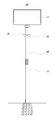
도 1은 본 발명의 일 구체예에 따른 스마트 태양광 보안 가로등 시스템의 정면도이다.
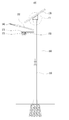
도 2는 본 발명의 일 구체예에 따른 스마트 태양광 보안 가로등 시스템의 측면도이다.
도 3은 도 2에 표시된 Ⅲ을 확대하여 도시한 도면이다.
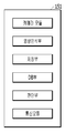
도 4는 도 1의 스마트 태양광 보안 가로등 시스템의 영상장치의 구성을 나타내는 블록도이다.1 is a front view of a smart sunlight security streetlight system in accordance with an embodiment of the present invention.
2 is a side view of a smart sunlight security streetlight system in accordance with an embodiment of the present invention.
3 is an enlarged view of III shown in Fig.
4 is a block diagram illustrating the configuration of an imaging apparatus of the smart solar light security streetlight system of FIG.
이하, 첨부된 도면을 참조하여 본 발명을 구체적으로 설명한다. 하기의 설명은 본 발명을 구체적인 예시를 들어 기술하는 것으로 이해되어야 하며, 본 발명의 기술적 사상이 하기의 설명에 한정되는 것은 아니다. 그리고 첨부된 도면은 본 발명의 이해를 돕기 위해 제공되는 것으로, 본 발명의 기술적 사상이 첨부된 도면에 한정되는 것은 아니다. Hereinafter, the present invention will be described in detail with reference to the accompanying drawings. It is to be understood that the following description is illustrative of the present invention, and the technical spirit of the present invention is not limited to the following description. BRIEF DESCRIPTION OF THE DRAWINGS The accompanying drawings, which are included to provide a further understanding of the invention and are incorporated in and constitute a part of this application, illustrate embodiments of the invention and, together with the description, serve to explain the principles of the invention.
도 1은 본 발명의 일 구체예에 따른 스마트 태양광 보안 가로등 시스템(100, 이하 가로등시스템으로 칭하기로 함)의 정면도이고, 도 2는 측면도이다. 1 is a front view of a smart sunlight security streetlight system 100 (hereinafter referred to as a streetlight system) according to one embodiment of the present invention, and Fig. 2 is a side view.
도 1 및 도 2를 참조하면, 가로등 시스템(100)은 메인 포스트(110), 태양광 패널(120), 분기 포스트(131,132), 에너지 저장 장치(미도시), 가로등(140), 영상장치(151,152), 제1 전력공급부(미도시), 제2 전력공급부(미도시)를 포함할 수 있다. 1 and 2, a
메인 포스트(110)는 지면에 직립 설치되고, 내부가 비어 있는 기둥형으로 형성될 수 있다. 메인 포스트(110)에는 컨트롤박스(160)가 설치될 수 있다. 컨트롤박스(160)는 가로등(140)을 비롯한 가로등 시스템(100)에 설치된 각종 장치들에 공급되는 전력을 제어하거나, 설정을 변경하기 위한 회로패널 및 사용자 인터페이스를 실장할 수 있다. The
태양광 패널(120)은 메인 포스트(110) 상단에 결합되는 것으로, 경사각을 조정 가능하도록 결합된다. 여기에서 경사각은 메인 포스트(110)의 상단을 기준으로 태양광 패널(120)의 면 부분이 기울어진 정도를 의미한다. 태양광 패널(120)의 경사각 조정에 대해서는 다른 도면을 참조하여 후술한다. 태양광 패널(120)은 태양광을 집적하는 복수의 솔라셀과, 상기 복수의 솔라셀이 배열되는 모듈판 등을 포함하며, 상용화 된 태양광 패널을 이용할 수 있는 바 구체적인 설명은 생략한다. 태양광 패널(120)은 태양에너지를 이용하여 전기를 생산한다. The
분기 포스트(131,132)는 메인 포스트(110) 상단측 측부로부터 연장 형성된다. 일 구체예에 있어서 도 1,2에 도시된 바와 같이 분기 포스트(131,132)는 메인 포스트(110)에 수직 방향으로 연장 형성되는 제1 분기 포스트(131)와, 제1 분기 포스트(132)와 소정 각도를 형성하도록 메인 포스트(110)에 연장 형성되는 제2 분기 포스트(132)를 포함할 수 있다. 필요에 따라 제1 분기 포스트(131)와 제2 분기 포스트(132) 사이를 연결하는 연결부재(미표기)가 추가 형성될 수 있다. 상기 연결부재는 제1 분기 포스트(131)에 의해 지지되어 제2 분기 포스트(132)를 지지하는 역할을 할 수 있다. 제1 분기 포스트(131)와 제2 분기 포스트(132)가 이루는 소정 각도는 특정되지 않는다. The branch posts 131 and 132 extend from the side of the upper end side of the
일 구체예에 있어서, 제1 분기 포스트(131)에는 영상장치(151,152)가 설치되고, 제2 분기 포스트(132)의 단부에는 가로등(140)이 설치될 수 있다. In one embodiment, the
영상장치(151,152)는 영상을 촬영하는 기능을 하며, 영상장치(151,152)의 구체적 구성에 대해서는 다른 도면을 참조하여 후술한다. 제1 분기 포스트(131)에 설치되는 영상장치(151,152)는 두 대일 수 있다. 예를 들어 도 1,2에 도시된 바와 같이 제1 분기 포스트(131)의 하부에는 영상을 획득하는 렌즈가 제1 방향을 향하도록 배치되는 제1 영상장치(151)와, 렌즈가 상기 제1 방향과는 다른 제2 방향을 향하도록 배치되는 제2 영상장치(152)가 각각 설치될 수 있다. 상기 제1 방향 및 제2 방향은 서로 반대되는 방향일 수 있다. 즉, 제1 영상장치(151)가 제1 분기 포스트(131)의 우측을 촬영하도록 설치될 때, 제2 영상장치(152)는 제1 분기 포스트(131)의 좌측을 촬영하도록 설치될 수 있다. 이 경우, 인간, 동물, 사물 등이 가로등 시스템(100)을 기준으로 우측에서 좌측으로 이동할 때에, 제1 영상장치(151)는 상기 인간, 동물, 사물(예컨대 차량) 등의 전면을 촬영할 수 있고, 제2 영상장치(152)는 후면을 촬영할 수 있다. 영상장치가 하나만 설치된 기존 보안 가로등의 경우에는 고정된 특정 뷰(view)만을 촬영할 수 있고, 영상장치를 제어에 의해 회전 가능하도록 설치하는 경우에도 뷰를 변경하는 것이 가능한 것이지 여전히 특정 뷰를 촬영하는 것은 변함이 없다. 하지만 본 발명에서와 같이 두 대의 영상장치를 서로 반대되는 방향으로 설치하는 경우에는 두 개의 특정 뷰를 촬영할 수 있으므로 보다 풍부한 정보를 획득할 수 있으며, 영상장치의 회전을 위한 별도의 구성이 요구되지 않으므로 회전구동부품, 전자제어부품 설치 등에 따른 제작비용 상승 요인이 없다는 장점이 있다. The
가로등(140)은 제2 분기 포스트(132)의 바깥쪽 단부에 설치될 수 있다. 가로등(140)은 상용화 된 가로등을 이용할 수 있으므로(예컨대 LED 가로등), 구체적인 설명은 생략한다. 일 구체예에 있어서, 가로등(140)은 디밍 제어될 수 있다. 디밍 제어는 주변 밝기 또는 배터리 잔량에 따라 조명의 밝기 등을 조절하여 제어하는 기술 일반을 의미한다. 또한 가로등(140)은 일몰 이후에 점등될 수 있도록 제어될 수 있다. 예를 들어 컨트롤박스(160)에는 타이머와, 상기 타이머에 따라 가로등(140)을 점등 또는 점멸시키는 제어회로가 설치될 수 있다. 이 경우 타이머에 설정된 시간에 따라 가로등(140)을 점등 또는 점멸시키도록 세팅할 수 있다. The
에너지 저장 장치(미도시)는 태양광 패널(120)로부터 생성되는 전력을 저장하는 기능을 한다. 그리고 저장된 전력을 가로등(140)에 공급하는 기능을 한다. 상기 에너지 저장 장치는 메인 포스트(110)의 내부, 또는 메인 포스트(110)에 설치된 컨트롤 박스의 내부, 또는 지중에 설치될 수 있다. 상기 에너지 저장 장치는 상용화 된 리튬전지, 나트륨황전지, 레독스플로우 전지 또는 슈퍼캐패시터 전지와 같은 배터리 방식이 사용될 수 있다. 상기 에너지 저장 장치는 태양광 패널(120)로부터 생성되는 전력을 저장함으로써 충전되고, 저장된 전력을 가로등(140)에 공급함으로써 방전될 수 있다. 가로등(140)은 상기 에너지 저장 장치로부터 공급받는 전력을 메인 전력으로 할 수 있다. An energy storage device (not shown) functions to store power generated from the
제1 전력공급부(미도시)는 영상장치(151,152) 및 컨트롤박스(160)에 상시 전력을 공급하는 기능을 할 수 있다. 상기 제1 전력공급부는 상용 전원과 연결될 수 있다. 영상장치(151,152)나 컨트롤박스(160)에는 전력 공급이 계속해서 이루어져야 한다. 영상장치(151,152)는 보안 목적으로 설치되는 것이므로 전력 문제로 작동이 중지되어서는 안되며, 컨트롤박스(160)에는 가로등 시스템(100)에서 수행하는 기능들을 제어하기 위한 각종 회로패널 등이 설치되기 때문이다. 따라서 상용 전원과 연결된 상기 제1 전력공급부를 통해 영상장치(151,152) 및 컨트롤박스(160)에 중단 없는 전력을 공급한다. The first power supply unit (not shown) may function to supply power to the
한편 제2 전력공급부(미도시)는 필요에 따라 가로등(140)에 보조 전력을 공급하는 기능을 할 수 있다. 가로등(140)은 상술한 것과 같이 태양광 패널(120)로부터 생성되는 전력을 상기 에너지 저장 장치를 통해 공급받게 되며, 태양광 패널(120)을 공급원으로 하는 전력이 메인 전력이다. 그러나 태양광 패널(120)의 전기 생산 프로세스 상, 에너지 저장 장치에 저장된 전력량이 부족할 수도 있다. 이를 테면 흐린 날이 계속되거나 장마철과 같이 일조량이 충분하지 않은 경우 태양광 패널(120)을 통해 생성되는 전력량이 불충분할 수 있기 때문이다. 그러나 이런 경우에도 가로등(140)은 점등되어야 하므로 상기 에너지 저장 장치의 충전량이 충분하지 않을 때에 보조적으로 제2 전력공급부를 통해 가로등(140)에 보조 전력을 공급할 수 있다. On the other hand, the second power supply unit (not shown) may function to supply auxiliary power to the
상기 제1 전력공급부 및 제2 전력공급부는 지중에 설치될 수 있으며, 이들과 연결된 전력선이 메인 포스트(110)의 내부를 통해 가설되어 가로등(140) 등에 연결될 수 있다. 일 구체예에 있어서, 상기 제1 전력공급부 및 제2 전력공급부는 하나의 전력공급부로 구성될 수도 있다. 이와 같은 경우에 있어서는 전력 공급 회로부에 릴레이 등의 회로 구성을 추가함으로써 필요에 따라 가로등(140)에 보조 전력을 공급하게 할 수 있다. The first power supply unit and the second power supply unit may be installed in the ground. Power lines connected to the first power supply unit and the second power supply unit may be installed through the interior of the
도면에 도시되지는 않았으나, 가로등 시스템(100)에는 각종 센서들이 설치될 수 있다. 예를 들어 가로등 시스템(100)에는 인체나 물체의 움직임을 감지하는 센서, 무선식별태그 인식 센서, 일조량 측정 센서, 온도 센서, 풍속 센서, 풍량 센서, 습도 센서, 진동 센서 중 적어도 1 이상이 장착될 수 있다. 상기 센서들은 메인 포스트(110), 분기 포스트(131,132) 또는 컨트롤박스(160)의 내외부에 선택적으로 설치될 수 있다. 이 때, 컨트롤박스(160)는 상기 센서들로부터 획득된 데이터를 수신하는 수신부와, 상기 데이터를 가공하거나 상기 데이터를 기반으로 정보를 생성하는 정보생성부와, 상기 데이터 내지 상기 정보를 정해진 수신처로 전송하는 통신부와, 가로등 시스템(100)에 설치된 각종 장치들을 제어하는 제어부를 포함할 수 있다. 상기 통신부는 상기 수신처로부터 데이터 또는 정보를 수신할 수도 있다. Although not shown in the drawings, various sensors may be installed in the
또한, 가로등 시스템(100)에는 스피커(미도시)가 설치될 수 있다. 일 예로 상기 스피커는 가로등 시스템(100)의 메인 포스트(110)에 설치될 수 있다. In addition, a speaker (not shown) may be installed in the
또한, 가로등 시스템(100)에는 전광판(미도시)가 설치될 수 있다. 일 예로 상기 전광판은 가로등 시스템(100)의 메인 포스트(110)에 세로 방향으로 설치되거나, 분기 포스트(131,132)에 가로 방향으로 설치될 수 있다. In addition, an electric signboard (not shown) may be installed in the
상술한 센서들, 스피커, 전광판을 통해 가로등 시스템(100)은 다음의 기능들을 수행할 수 있다. The
(1) 무선식별태그 인식 기능: 가로등 시스템(100)은 컨트롤박스(160) 등에 설치된 무선식별태그 인식 센서를 통해, 가로등 시스템(100)에 근접하는 무선식별태그를 인식할 수 있다. 상기 무선식별태그는 범죄자에게 착용되는 전자발찌에 부착된 무선식별태그, 영유아에게 부착되는 무선식별태그, 특정 목적을 위해 차량에 부착되는 무선식별태그 등일 수 있다. 일 구체예에 있어서, 무선식별태그가 부착된 전자발찌를 착용한 범죄자가 가로등 시스템(100)에 근접하면, 가로등 시스템(100)에 설치된 무선식별태그 인식 센서는 상기 무선식별태그를 인식할 수 있다. 그리고 상기 무선식별태그 인식 센서는 무선식별태그를 인식했음을 알리는 취지의 신호 데이터를 컨트롤박스(160)에 설치된 수신부로 전송할 수 있다. 상기 수신부에서 상기 신호 데이터를 수신하면, 통신부를 통해 정해진 수신처(예를 들면, 경찰서)로 전송할 수 있다. 또는 상기 수신부에서 상기 신호 데이터를 수신하면, 제어부를 통해 기 지정된 음성이 스피커를 통해 외부로 출력되게 하거나, 기 지정된 메시지가 전광판에 표시되도록 할 수 있다. (1) Wireless identification tag recognition function : The
(2) 인체/물체 움직임 감지: 가로등 시스템(100)은 컨트롤박스(160) 등에 설치된 인체나 물체의 움직임을 감지하는 센서(이하, 움직임 감지 센서)를 통해, 가로등 시스템(100)에 근접하는 인체, 물체 등을 감지할 수 있다. 일 구체예에 있어서, 인체, 물체 등이 가로등 시스템(100)에 근접할 때에 가로등 시스템(100)에 설치된 움직임 감지 센서는 인체, 물체 등의 움직임을 인식할 수 있다. 그리고 상기 움직임 감지 센서는 인체, 물체 등이 움직임을 알리는 취지의 신호 데이터를 컨트롤박스(160)에 설치된 수신부로 전송할 수 있다. 그리고 상기 수신부에서 상기 신호 데이터를 수신하면, 제어부를 통해 기 지정된 음성(예를 들어 국가 재난 방송 등)이 스피커를 통해 외부로 출력되게 하거나, 기 지정된 메시지가 전광판에 표시되도록 할 수 있다. (2) Human Body / Object Movement Detection : The
또는, 움직임 감지 센서를 통해 인체 또는 물체 등을 감지할 수 있으므로, 가로등 시스템(100)에 근접하는 인원수나 물체수에 대한 정보를 정보생성부에서 생성할 수 있는 바, 가로등 시스템(100)의 일간, 주간 등 설정된 주기에 따른 유동 인구 내지 유동 차량 등에 관련된 정보를 획득할 수 있다. Since information on the number of people or the number of objects in proximity to the
(3) 기상 관측 데이터 수집: 가로등 시스템(100)은 컨트롤박스(160) 등에 설치된 일조량 측정 센서, 온도 센서, 풍속 센서, 풍량 센서, 습도 센서, 진동 센서 등을 통해 가로등 시스템(100)이 설치된 위치를 포함하는 주변 환경의 기상 관측 데이터들을 수집할 수 있다. 일 구체예에 있어서, 상기 센서들은 가로등 시스템(100)이 설치된 위치를 포함하는 주변의 일조량, 온도, 풍속, 풍량, 습도, 진동량 등을 측정하고, 환경 데이터들을 컨트롤박스(160)에 설치된 수신부로 전송할 수 있다. 상기 수신부에서 상기 환경 데이터를 수신하면, 정보생성부를 통해 상기 환경 데이터들을 기반으로 기상 정보를 생성하거나, 통신부를 통해 상기 환경 데이터들을 정해진 수신처로 전송할 수 있다. 상기 전송은 특정 주기(매일 정해진 시간, 또는 매주 정해진 날짜)로 전송될 수 있다. 이와 같이 각종 센서들을 통해 수집된 환경 데이터들을 기반으로 해당 지역의 기상 정보를 생성하는 것이 가능하다. 경우에 따라, 컨트롤박스(160)의 제어부는 상기 환경 데이터들을 가로등 시스템(100)에 설치된 전광판을 통해 외부로 표시할 수도 있다. (3) Weather Observation Data Acquisition : The
상술한 기능들 이외에도 가로등 시스템(100)은 상술한 센서들, 스피커, 전광판을 통해 다양한 기능들을 수행할 수 있을 것이다. In addition to the functions described above, the
이하, 가로등 시스템(100)에서 태양광 패널(120)의 경사각 조정 구성에 대해 설명한다. 관련하여, 도 3은 도 2에 표시된 Ⅲ을 확대하여 도시한 도면이다. Hereinafter, a configuration for adjusting the inclination angle of the
도 3을 참조하면, 가로등 시스템(100)은 태양광 패널(120)의 경사각 조정을 위해 메인 포스트(110) 상단의 앞쪽에 직립 설치되고 태양광 패널(120)의 하부 앞쪽과 결합하는 제1 포스트(111)와, 메인 포스트(110) 상단의 뒤쪽에 직립 설치되는 것으로, 하단부가 내부에 삽입되어 높이 조절이 가능한 높이조절부재(113)가 측부에 형성된 복수의 높이조절홀(112a)을 통해 결합되고, 높이조절부재(113)의 상단부가 태양광 패널(120)의 하부 뒤쪽과 힌지(113a)를 통해 결합하는 제2 포스트(112)를 포함할 수 있다.3, the
일 구체예에 있어서, 제2 포스트(112)에는 도 3에 도시된 바와 같이 측부에 일렬로 배열된 3개의 높이조절홀(112a)이 있고, 높이조절부재(113)는 이 중 어느 하나의 높이조절홀(112a)과 볼팅 결합될 수 있다(높이조절부재(113)의 양측부에는 높이조절홀(112a)과 결합을 위한 결합홀(미도시)가 형성될 수 있음). 예컨대 높이조절부재(113)의 측부 아래쪽에 결합홀이 형성되어 있고, 상기 결합홀과 가장 위쪽에 위치한 높이조절홀(112a)이 볼팅 결합하는 경우에 태양광 패널(120)의 경사각은 최대가 된다. 그리고 상기 결합홀과 가장 아래쪽에 위치한 높이조절홀(112a)이 볼팅 결합하는 경우에 태양광 패널(120)의 경사각은 최소가 된다. 이렇듯 높이조절부재(113)를 높이조절홀(112a)과의 결합 위치에 따라 높이를 조절함으로써 태양광 패널(120)의 경사각을 조절할 수 있으며, 이에 따라 계절별로 태양광 패널(120)의 경사각을 조절할 수 있다. 태양 고도와 태양의 방위각에 따라 최적의 태양광 패널(120)의 설치 각도를 갖도록 태양광 패널(120)의 경사각을 조절함으로써 발전효율을 향상시킬 수 있기 때문이다. 태양광 패널이 설치된 종래 가로등의 경우 태양광 패널을 구동모터, 자동제어회로 등을 통해 자동적으로 태양광 패널의 경사각을 조절하는 기술이 공지된 바 있다. 그러나 이러한 방식은 제작비용 상승의 원인이 되는 바, 본 발명에 따른 가로등 시스템(100)에서는 높이조절부재(112a)를 높이조절홀(112a)과의 결합 위치에 따라 높이를 조절하는 상대적으로 간단한 방식을 통해 태양광 패널(120)의 경사각을 조정함으로써, 제작비용을 절감시키면서도 태양광 패널(120)의 경사각을 계절이나 태양의 위치 등에 따라 최적으로 조정시키는 것이 가능하다. 태양광 패널(120)의 최적 경사각 산출은 공지된 방식에 의할 수 있고, 상기 경사각을 맞출 수 있도록 높이조절부재(113)의 사이즈나 높이조절홀(112a)의 개수, 간격 등을 조정할 수 있을 것이다. In one embodiment, the
이하, 영상장치(151,152)의 세부 구성에 대해 설명하도록 한다. 관련하여, 도 4는 도 1의 가로등 시스템(100)의 영상장치(151)의 구성을 나타내는 블록도이다. 상술하였듯 가로등 시스템(100)은 두 대의 영상장치(151,152)가 설치될 수 있으며, 제1 영상장치(151) 및 제2 영상장치(152)는 세부구성이 동일 또는 유사할 수 있으므로, 이하에서는 제1 영상장치(151)를 중심으로 설명하도록 한다(이하에서는 제1 영상장치(151)를 영상장치(151)로 기재한다).Hereinafter, the detailed configuration of the
영상장치(151)는 영상을 획득하는 카메라 모듈과, 기 설정된 알고리즘에 따라 획득된 영상에서 불꽃, 연기, 안면 및 차량 번호판 중 적어도 1 이상을 인식하는 영상인식부와, 상기 불꽃, 연기, 안면 및 차량 번호판 중 적어도 1 이상이 인식되는 경우에는 인식된 부분을 확대하여 이미지로 저장하는 저장부와, 특정 안면 및 차량 번호판에 대한 정보가 기록되는 DB부와, 상기 저장부에 저장된 이미지와 상기 DB부에 기록된 정보를 상호 비교하여 상기 이미지와 정보의 일치 여부를 판단하는 판단부와, 상기 판단부에서 상기 이미지와 정보가 일치한다고 판단하는 경우에 인식 메시지를 지정된 수신처로 전송하거나 상기 저장부에 불꽃, 연기 이미지가 저장되는 경우 지정된 수신처로 전송하는 통신 모듈을 포함할 수 있다. The
상기 카메라 모듈은 일반적으로 영상을 획득하는 카메라 모듈에 해당한다. 상기 영상인식부는 기 설정된 알고리즘에 따라 획득된 영상에서 불꽃, 연기, 안면 및 차량 번호판 중 적어도 1 이상을 인식한다. 상기 알고리즘은 영상 인식과 관련된 공지의 알고리즘을 이용할 수 있으며, 예를 들면 획득한 영상에서 특징점(feature point)들을 추출하고, 상기 특징점들로 이루어진 매트릭스를 획득하고 변환함으로써 영상에서 불꽃, 연기, 안면 및 차량 번호판 들을 인식할 수 있다. 상기 저장부에서는 상기 영상인식부에서 인식된 영상을 저장하되, 인식된 불꽃, 연기, 안면 및 차량 번호판 부분을 확대하여 이미지로 저장하게 된다. 이미지 포맷은 특정되지 않는다. 상기 DB부에는 특정 안면 및 차량 번호판에 대한 정보가 기록된다. 예를 들면 특정 인물의 안면 이미지나, 특정 차량 번호판에 대한 정보가 기록될 수 있으며, 상기 정보는 상기 통신 모듈을 통해 수신될 수 있다. 상기 판단부에서는 상기 저장부에 저장된 이미지와 상기 DB부에 기록된 정보를 상호 비교하여 상기 이미지와 정보의 일치 여부를 판단한다. 상기 판단은 공지의 이미지 비교 알고리즘, 영상 비교 알고리즘을 통해 이루어질 수 있다. 상기 판단부에서 일치 여부를 판단한 결과, 상기 이미지와 정보가 일치하는 경우에는 획득된 이미지의 정보 가치가 높아질 수 있으므로 상기 통신 모듈에서는 인식 메시지(이미지와 DB에 기록된 정보가 일치한다는 취지를 기재함)를 지정된 수신처로 전송할 수 있다. 경우에 따라서는 상기 인식 메시지와 상기 저장부에 저장되어 있는 이미지를 함께 전송할 수 있다. 또는 저장부에 불꽃, 연기 이미지가 저장되는 경우 지정된 수신처로 상기 이미지를 전송할 수 있다. The camera module generally corresponds to a camera module for acquiring an image. The image recognition unit recognizes at least one of flame, smoke, face, and license plate in the acquired image according to a predetermined algorithm. The algorithm can use a known algorithm related to image recognition, for example, extracting feature points from an acquired image, acquiring and transforming a matrix of the feature points, thereby generating sparks, smoke, Vehicle license plates can be recognized. In the storage unit, the image recognized by the image recognition unit is stored, and the recognized flame, smoke, face, and license plate portion are enlarged and stored as an image. The image format is not specified. In the DB unit, information about a specific face and a license plate is recorded. For example, a face image of a specific person or information about a specific license plate may be recorded, and the information may be received through the communication module. The determination unit compares the image stored in the storage unit and the information recorded in the DB unit to determine whether the image matches the information. The determination may be made through a known image comparison algorithm or an image comparison algorithm. As a result of the determination by the determination unit, if the image and the information match, the information value of the obtained image may be increased. Therefore, the communication module records a recognition message ) To the designated destination. In some cases, the recognition message and the image stored in the storage unit may be transmitted together. Or when the flame or smoke image is stored in the storage unit, the image can be transferred to the designated destination.
상술한 바와 같이 구성되는 영상장치(151)를 통해, 특정 수신처에서는 가로등 시스템(100)에 근접하는 인물, 차량 번호판에 대해 가치 있는 정보를 획득할 수 있다. 예를 들어 수배 중인 범죄자가 가로등 시스템(100)에 근접하고, 상기 범죄자의 안면 정보가 영상장치(151)의 DB부에 저장되어 있을 경우 영상장치(151)는 상기 범죄자의 안면을 인식하고, 상기 안면 이미지를 확대하여 저장하고 상기 DB부에 기록된 안면 정보와 비교하여 일치 여부를 판단하고, 인식 메시지를 특정 수신처로 전송할 수 있으므로, 범죄 예방 또는 범죄자 검거에 도움이 될 수 있다. 뿐만 아니라 가로등 시스템(100)이 설치된 위치를 포함하여 근접 거리에서 화재가 발생하였을 경우, 영상장치(151)를 통해 불꽃, 연기 등을 인식하여 특정 수신처로 보낼 수 있으므로 화재 발생 사실이 빠르게 전파됨으로써 신속하게 후속 조치들을 취할 수 있다.Through the
상술한 바와 같이, 본 발명의 구체예들에 따른 스마트 태양광 보안 가로등 시스템은 보안에 필요한 영상장치 및 컨트롤박스에는 상시 전력을 공급하고, 밤에만 점등하는 가로등은 태양광 패널 및 보조 전력을 병행하여 전력을 공급함으로써 안정적으로 전력 공급이 가능하다. 또한, 설치되는 한 쌍의 영상장치를 통해 불꽃, 연기, 안면 및 차량 번호판을 인식하고 기록된 정보와 상호 비교하여 그 결과를 지정된 수신처로 전송하게 함으로써, 주변의 화재 감지, 사전에 입력된 범죄자 내지 수배 차량 등을 인식 가능하다. 또한, 1 이상의 센서를 장착하여 가로등이 설치된 주변의 환경 및 위치 정보 등을 획득할 수 있고, 이들 정보들을 이용하여 다양한 방식으로 활용될 수 있다.As described above, the smart solar security streetlight system according to embodiments of the present invention can provide a constant power to an image device and a control box necessary for security, and a streetlight that lights only at night can be operated in parallel with a solar panel and auxiliary power It is possible to supply electric power stably by supplying electric power. In addition, by recognizing the flame, the smoke, the face, and the license plate through a pair of installed image devices and comparing the information with the recorded information, the result is sent to the designated destination, so that the surrounding fire detection, And the like can be recognized. In addition, it is possible to acquire environment and location information of the surroundings in which the streetlight is installed by mounting one or more sensors, and can be utilized in various ways using the information.
이상, 본 발명의 구현예들에 대하여 설명하였다. 그러나 본 발명이 속하는 기술분야에서 통상의 지식을 가진 자라면 청구범위에 기재된 본 발명의 기술적 사상의 범위 내에서 기술의 구체적 적용에 따른 단순한 설계변경, 일부 구성요소의 생략, 단순한 용도의 변경 등 본 발명을 다양하게 변형할 수 있을 것이며, 이러한 변형 역시 본 발명의 권리범위 내에 포함됨은 자명하다.Embodiments of the present invention have been described above. However, it will be understood by those skilled in the art that various changes in form and details may be made therein without departing from the spirit and scope of the present invention as defined by the appended claims. It will be understood that various modifications may be made in the invention, and that such modifications are also included within the scope of the present invention.
100: 스마트 태양광 보안 가로등 시스템
110: 메인 포스트
120: 태양광 패널
131,132: 분기 포스트
140: 가로등
151,152: 영상장치
160: 컨트롤박스100: Smart solar security streetlight system
110: main post 120: solar panel
131, 132: branch post 140: streetlight
151, 152: Imaging device 160: Control box
Claims (5)
상기 메인 포스트 상단에 경사각을 조정 가능하도록 결합되는 태양광 패널;
상기 메인 포스트 상단측 측부로부터 연장 형성되는 분기 포스트;
상기 태양광 패널로부터 생성되는 전력을 저장하는 에너지 저장 장치;
상기 분기 포스트에 설치되고, 상기 에너지 저장 장치로부터 메인 전력을 공급 받는 가로등;
상기 분기 포스트에 설치되어 영상을 촬영하며, 영상인식기능, 안면인식기능 및 글자인식기능을 갖추고 있어 기 설정된 조건에 따라 촬영한 영상의 인식 메시지를 지정된 수신처로 전송하는 영상장치;
상기 영상장치 및 컨트롤박스에 상시 전력을 공급하는 제1 전력공급부; 및
필요에 따라 상기 가로등에 보조 전력을 공급하는 제2 전력공급부를 포함하는 스마트 태양광 보안 가로등 시스템.A main post mounted upright on the ground and coupled with the control box;
A solar panel coupled to an upper end of the main post so as to be able to adjust an inclination angle;
A branch post extending from the side portion on the upper side of the main post;
An energy storage device for storing power generated from the solar panel;
A street lamp installed in the branch post and supplied with main power from the energy storage device;
An imaging device installed in the branch post for capturing an image and having an image recognition function, a facial recognition function, and a character recognition function to transmit a recognition message of an image photographed according to predetermined conditions to a designated destination;
A first power supply unit for supplying constant power to the image device and the control box; And
And a second power supply unit for supplying auxiliary power to the street lamp as needed.
상기 메인 포스트 상단의 앞쪽에 직립 설치되고 상기 태양광 패널의 하부 앞쪽과 결합하는 제1 포스트; 및
상기 메인 포스트 상단의 뒤쪽에 직립 설치되는 것으로, 하단부가 내부에 삽입되어 높이 조절이 가능한 높이조절부재가 측부에 형성된 복수의 높이조절홀을 통해 결합되고, 상기 높이조절부재의 상단부가 상기 태양광 패널의 하부 뒤쪽과 힌지 결합하는 제2 포스트를 포함하고,
상기 태양광 패널은 상기 높이조절부재의 높이 조절에 의해 기울기가 조정되는 스마트 태양광 보안 가로등 시스템.The method according to claim 1,
A first post mounted upright on a front side of an upper end of the main post and engaged with a lower front side of the solar panel; And
A height adjustment member having a lower end portion inserted therein and being adjustable in height is coupled through a plurality of height adjustment holes formed in a side portion of the main post, And a second post hinged to the lower rear side of the second post,
Wherein the solar panel is tilted by height adjustment of the height adjustment member.
상기 분기 포스트는 상기 메인 포스트에 수직 방향으로 연장 형성되는 제1 분기 포스트와, 상기 제1 분기 포스트와 소정 각도를 형성하도록 상기 메인 포스트에 연장 형성되는 제2 분기 포스트를 포함하고,
상기 제1 분기 포스트의 하부에는 영상을 획득하는 렌즈가 제1 방향을 향하도록 배치되는 제1 영상장치와, 렌즈가 상기 제1 방향과는 다른 제2 방향을 향하도록 배치되는 제2 영상장치가 각각 설치되고,
상기 제2 분기 포스트의 바깥쪽 단부에는 상기 가로등이 설치되는 스마트 태양광 보안 가로등 시스템.The method according to claim 1 or 2,
Wherein the branch post includes a first branch post extending in a direction perpendicular to the main post and a second branch post extending from the main post to form an angle with the first branch post,
A first image device disposed at a lower portion of the first branch post such that a lens for acquiring an image is disposed in a first direction and a second image device disposed in a second direction different from the first direction, Respectively,
And the streetlight is installed at an outer end of the second branch post.
상기 제1 영상장치 및 제2 영상장치는, 영상을 획득하는 카메라 모듈과, 기 설정된 알고리즘에 따라 획득된 영상에서 불꽃, 연기, 안면 및 차량 번호판 중 적어도 1 이상을 인식하는 영상인식부와, 상기 불꽃, 연기, 안면 및 차량 번호판 중 적어도 1 이상이 인식되는 경우에는 인식된 부분을 확대하여 이미지로 저장하는 저장부와, 특정 안면 및 차량 번호판에 대한 정보가 기록되는 DB부와, 상기 저장부에 저장된 이미지와 상기 DB부에 기록된 정보를 상호 비교하여 상기 이미지와 정보의 일치 여부를 판단하는 판단부와, 상기 판단부에서 상기 이미지와 정보가 일치한다고 판단하는 경우에 인식 메시지를 지정된 수신처로 전송하거나 상기 저장부에 불꽃, 연기 이미지가 저장되는 경우 지정된 수신처로 전송하는 통신 모듈을 포함하는 스마트 태양광 보안 가로등 시스템.The method of claim 3,
Wherein the first image device and the second image device include a camera module for acquiring an image, an image recognizer for recognizing at least one of flame, smoke, face, and license plate in an image obtained according to a predetermined algorithm, A DB unit for storing information on a specific face and a license plate, and a storage unit for storing information on a specific face and a license plate, A determination unit for comparing the stored image with the information recorded in the DB unit to determine whether or not the image matches the information; and a determination unit for determining whether the image matches the information, Or a communication module for transmitting a fire image to a designated destination when a fire image or smoke image is stored in the storage unit As a system.
인체나 물체의 움직임을 감지하는 센서, 무선식별태그 인식 센서, 일조량 측정 센서, 온도 센서, 풍속 센서, 풍량 센서, 습도 센서, 진동 센서 중 적어도 1 이상이 장착되고, 상기 컨트롤박스는 상기 센서들로부터 획득된 데이터를 수신하는 수신부와, 상기 데이터를 정해진 수신처로 전송하는 통신부를 포함하는 스마트 태양광 보안 가로등 시스템.The method according to claim 1 or 2,
At least one of a sensor for detecting movement of a human body or an object, a wireless identification tag recognition sensor, a sunshine measurement sensor, a temperature sensor, an wind speed sensor, an airflow sensor, a humidity sensor and a vibration sensor is mounted, A reception unit for receiving the acquired data; and a communication unit for transmitting the data to a predetermined destination.
Priority Applications (1)
| Application Number | Priority Date | Filing Date | Title |
|---|---|---|---|
| KR1020160108103A KR20180023195A (en) | 2016-08-25 | 2016-08-25 | Smart sunlight security street light system |
Applications Claiming Priority (1)
| Application Number | Priority Date | Filing Date | Title |
|---|---|---|---|
| KR1020160108103A KR20180023195A (en) | 2016-08-25 | 2016-08-25 | Smart sunlight security street light system |
Publications (1)
| Publication Number | Publication Date |
|---|---|
| KR20180023195A true KR20180023195A (en) | 2018-03-07 |
Family
ID=61689080
Family Applications (1)
| Application Number | Title | Priority Date | Filing Date |
|---|---|---|---|
| KR1020160108103A KR20180023195A (en) | 2016-08-25 | 2016-08-25 | Smart sunlight security street light system |
Country Status (1)
| Country | Link |
|---|---|
| KR (1) | KR20180023195A (en) |
Cited By (7)
| Publication number | Priority date | Publication date | Assignee | Title |
|---|---|---|---|---|
| CN108282744A (en) * | 2018-03-30 | 2018-07-13 | 浙江方大智控科技有限公司 | Wisdom traffic system based on wisdom lamp stand |
| CN108758512A (en) * | 2018-04-03 | 2018-11-06 | 芜湖孺子牛节能环保技术研发有限公司 | A kind of environment protection solar street lamp that daylighting effect is good |
| KR20200095698A (en) | 2019-02-01 | 2020-08-11 | 광주대학교산학협력단 | ESS System for Stand-alone Photovoltaic Streetlight equipped with IoT Module |
| KR20210088784A (en) * | 2020-01-06 | 2021-07-15 | (주)에이엘씨 | System for Operating Smart Street Light with Safety based on Location |
| KR20210101910A (en) | 2020-02-11 | 2021-08-19 | (주)큐디 | Smart Solar Street Light |
| KR20220129297A (en) | 2021-03-16 | 2022-09-23 | 주식회사 늘디딤 | Solar street light controller with dimming function and broadcasting function |
| KR20220129262A (en) | 2021-03-16 | 2022-09-23 | 주식회사 에니텍시스 | Solar street light that can wash the upper surface of the solar panel |
-
2016
- 2016-08-25 KR KR1020160108103A patent/KR20180023195A/en not_active Application Discontinuation
Cited By (8)
| Publication number | Priority date | Publication date | Assignee | Title |
|---|---|---|---|---|
| CN108282744A (en) * | 2018-03-30 | 2018-07-13 | 浙江方大智控科技有限公司 | Wisdom traffic system based on wisdom lamp stand |
| CN108282744B (en) * | 2018-03-30 | 2023-09-15 | 浙江方大智控科技有限公司 | Intelligent traffic system based on intelligent lamp post |
| CN108758512A (en) * | 2018-04-03 | 2018-11-06 | 芜湖孺子牛节能环保技术研发有限公司 | A kind of environment protection solar street lamp that daylighting effect is good |
| KR20200095698A (en) | 2019-02-01 | 2020-08-11 | 광주대학교산학협력단 | ESS System for Stand-alone Photovoltaic Streetlight equipped with IoT Module |
| KR20210088784A (en) * | 2020-01-06 | 2021-07-15 | (주)에이엘씨 | System for Operating Smart Street Light with Safety based on Location |
| KR20210101910A (en) | 2020-02-11 | 2021-08-19 | (주)큐디 | Smart Solar Street Light |
| KR20220129297A (en) | 2021-03-16 | 2022-09-23 | 주식회사 늘디딤 | Solar street light controller with dimming function and broadcasting function |
| KR20220129262A (en) | 2021-03-16 | 2022-09-23 | 주식회사 에니텍시스 | Solar street light that can wash the upper surface of the solar panel |
Similar Documents
| Publication | Publication Date | Title |
|---|---|---|
| KR20180023195A (en) | Smart sunlight security street light system | |
| KR101956529B1 (en) | Multi-function smart type streetlamp | |
| JP4418012B1 (en) | Outdoor lights that can be installed immediately at the selected installation location | |
| CN107575820A (en) | A kind of Multifunctional City intelligent control solar LED street lamp | |
| KR101074116B1 (en) | Streetlight apparatus | |
| CN206055509U (en) | A kind of multi-functional street lamp | |
| KR101459528B1 (en) | Video surveillance system using street light | |
| KR20160124504A (en) | A multi-functional street light system | |
| CN209371087U (en) | A kind of multifunctional intellectual street lamp based on Internet of Things | |
| CN109915776A (en) | The detection system and detection method of a kind of pavement of road average brightness and average illumination | |
| KR102259813B1 (en) | Security CCTV system for smart street light | |
| KR20210031273A (en) | Functional iot street lamp | |
| KR101837005B1 (en) | Apparatus for Safety Notice Solar light | |
| CN106482931A (en) | road light source monitoring device, monitoring method and monitoring system | |
| CN215868160U (en) | Take lighting apparatus's wisdom parking video stake | |
| CN213152184U (en) | Animal identification type field monitoring system based on convolutional neural network | |
| CN208983206U (en) | Intelligent road-lamp | |
| KR20230016741A (en) | Hybrid smartpole management system | |
| CN206100581U (en) | Street lamp automatic control system | |
| CN207880616U (en) | Outdoor multifunctional landscape lamp structure | |
| CN210627487U (en) | Traffic prompting system | |
| KR20090035393A (en) | Violation car enforcement system | |
| JP3221685U (en) | 24 hour surveillance camera device for street light | |
| CN207491254U (en) | Intelligent and safe lighting circuit | |
| CN101915410A (en) | Intelligent solar photovoltaic power supply lighting device |
Legal Events
| Date | Code | Title | Description |
|---|---|---|---|
| A201 | Request for examination | ||
| E902 | Notification of reason for refusal | ||
| E601 | Decision to refuse application |