KR20180020249A - Vehicle air conditioning system - Google Patents
Vehicle air conditioning system Download PDFInfo
- Publication number
- KR20180020249A KR20180020249A KR1020187001914A KR20187001914A KR20180020249A KR 20180020249 A KR20180020249 A KR 20180020249A KR 1020187001914 A KR1020187001914 A KR 1020187001914A KR 20187001914 A KR20187001914 A KR 20187001914A KR 20180020249 A KR20180020249 A KR 20180020249A
- Authority
- KR
- South Korea
- Prior art keywords
- water temperature
- temperature data
- cooling water
- mode
- air
- Prior art date
- Legal status (The legal status is an assumption and is not a legal conclusion. Google has not performed a legal analysis and makes no representation as to the accuracy of the status listed.)
- Granted
Links
Images


Classifications
-
- B—PERFORMING OPERATIONS; TRANSPORTING
- B60—VEHICLES IN GENERAL
- B60H—ARRANGEMENTS OF HEATING, COOLING, VENTILATING OR OTHER AIR-TREATING DEVICES SPECIALLY ADAPTED FOR PASSENGER OR GOODS SPACES OF VEHICLES
- B60H1/00—Heating, cooling or ventilating devices
- B60H1/00642—Control systems or circuits; Control members or indication devices for heating, cooling or ventilating devices
- B60H1/00814—Control systems or circuits characterised by their output, for controlling particular components of the heating, cooling or ventilating installation
- B60H1/00878—Control systems or circuits characterised by their output, for controlling particular components of the heating, cooling or ventilating installation the components being temperature regulating devices
- B60H1/00885—Controlling the flow of heating or cooling liquid, e.g. valves or pumps
-
- B—PERFORMING OPERATIONS; TRANSPORTING
- B60—VEHICLES IN GENERAL
- B60H—ARRANGEMENTS OF HEATING, COOLING, VENTILATING OR OTHER AIR-TREATING DEVICES SPECIALLY ADAPTED FOR PASSENGER OR GOODS SPACES OF VEHICLES
- B60H1/00—Heating, cooling or ventilating devices
- B60H1/00642—Control systems or circuits; Control members or indication devices for heating, cooling or ventilating devices
- B60H1/00735—Control systems or circuits characterised by their input, i.e. by the detection, measurement or calculation of particular conditions, e.g. signal treatment, dynamic models
- B60H1/00807—Control systems or circuits characterised by their input, i.e. by the detection, measurement or calculation of particular conditions, e.g. signal treatment, dynamic models the input being a specific way of measuring or calculating an air or coolant temperature
-
- B—PERFORMING OPERATIONS; TRANSPORTING
- B60—VEHICLES IN GENERAL
- B60H—ARRANGEMENTS OF HEATING, COOLING, VENTILATING OR OTHER AIR-TREATING DEVICES SPECIALLY ADAPTED FOR PASSENGER OR GOODS SPACES OF VEHICLES
- B60H1/00—Heating, cooling or ventilating devices
- B60H1/00314—Arrangements permitting a rapid heating of the heating liquid
-
- B—PERFORMING OPERATIONS; TRANSPORTING
- B60—VEHICLES IN GENERAL
- B60H—ARRANGEMENTS OF HEATING, COOLING, VENTILATING OR OTHER AIR-TREATING DEVICES SPECIALLY ADAPTED FOR PASSENGER OR GOODS SPACES OF VEHICLES
- B60H1/00—Heating, cooling or ventilating devices
- B60H1/00642—Control systems or circuits; Control members or indication devices for heating, cooling or ventilating devices
- B60H1/00814—Control systems or circuits characterised by their output, for controlling particular components of the heating, cooling or ventilating installation
- B60H1/00821—Control systems or circuits characterised by their output, for controlling particular components of the heating, cooling or ventilating installation the components being ventilating, air admitting or air distributing devices
- B60H1/00828—Ventilators, e.g. speed control
-
- B—PERFORMING OPERATIONS; TRANSPORTING
- B60—VEHICLES IN GENERAL
- B60H—ARRANGEMENTS OF HEATING, COOLING, VENTILATING OR OTHER AIR-TREATING DEVICES SPECIALLY ADAPTED FOR PASSENGER OR GOODS SPACES OF VEHICLES
- B60H1/00—Heating, cooling or ventilating devices
- B60H1/02—Heating, cooling or ventilating devices the heat being derived from the propulsion plant
- B60H1/04—Heating, cooling or ventilating devices the heat being derived from the propulsion plant from cooling liquid of the plant
- B60H1/08—Heating, cooling or ventilating devices the heat being derived from the propulsion plant from cooling liquid of the plant from other radiator than main radiator
- B60H1/10—Heating, cooling or ventilating devices the heat being derived from the propulsion plant from cooling liquid of the plant from other radiator than main radiator the other radiator being situated in a duct capable of being connected to atmosphere outside vehicle
- B60H1/12—Heating, cooling or ventilating devices the heat being derived from the propulsion plant from cooling liquid of the plant from other radiator than main radiator the other radiator being situated in a duct capable of being connected to atmosphere outside vehicle using an air blower
-
- B—PERFORMING OPERATIONS; TRANSPORTING
- B60—VEHICLES IN GENERAL
- B60H—ARRANGEMENTS OF HEATING, COOLING, VENTILATING OR OTHER AIR-TREATING DEVICES SPECIALLY ADAPTED FOR PASSENGER OR GOODS SPACES OF VEHICLES
- B60H1/00—Heating, cooling or ventilating devices
- B60H1/00007—Combined heating, ventilating, or cooling devices
- B60H1/00021—Air flow details of HVAC devices
- B60H1/00064—Air flow details of HVAC devices for sending air streams of different temperatures into the passenger compartment
-
- B—PERFORMING OPERATIONS; TRANSPORTING
- B60—VEHICLES IN GENERAL
- B60H—ARRANGEMENTS OF HEATING, COOLING, VENTILATING OR OTHER AIR-TREATING DEVICES SPECIALLY ADAPTED FOR PASSENGER OR GOODS SPACES OF VEHICLES
- B60H1/00—Heating, cooling or ventilating devices
- B60H1/00642—Control systems or circuits; Control members or indication devices for heating, cooling or ventilating devices
- B60H1/00814—Control systems or circuits characterised by their output, for controlling particular components of the heating, cooling or ventilating installation
- B60H1/00878—Control systems or circuits characterised by their output, for controlling particular components of the heating, cooling or ventilating installation the components being temperature regulating devices
- B60H1/00892—Devices specially adapted for avoiding uncomfortable feeling, e.g. sudden temperature changes
-
- B—PERFORMING OPERATIONS; TRANSPORTING
- B60—VEHICLES IN GENERAL
- B60H—ARRANGEMENTS OF HEATING, COOLING, VENTILATING OR OTHER AIR-TREATING DEVICES SPECIALLY ADAPTED FOR PASSENGER OR GOODS SPACES OF VEHICLES
- B60H1/00—Heating, cooling or ventilating devices
- B60H1/02—Heating, cooling or ventilating devices the heat being derived from the propulsion plant
- B60H1/04—Heating, cooling or ventilating devices the heat being derived from the propulsion plant from cooling liquid of the plant
- B60H1/08—Heating, cooling or ventilating devices the heat being derived from the propulsion plant from cooling liquid of the plant from other radiator than main radiator
-
- B—PERFORMING OPERATIONS; TRANSPORTING
- B60—VEHICLES IN GENERAL
- B60H—ARRANGEMENTS OF HEATING, COOLING, VENTILATING OR OTHER AIR-TREATING DEVICES SPECIALLY ADAPTED FOR PASSENGER OR GOODS SPACES OF VEHICLES
- B60H1/00—Heating, cooling or ventilating devices
- B60H1/32—Cooling devices
- B60H1/3204—Cooling devices using compression
- B60H1/3205—Control means therefor
- B60H1/3219—Control means therefor for improving the response time of a vehicle refrigeration cycle
-
- B—PERFORMING OPERATIONS; TRANSPORTING
- B60—VEHICLES IN GENERAL
- B60H—ARRANGEMENTS OF HEATING, COOLING, VENTILATING OR OTHER AIR-TREATING DEVICES SPECIALLY ADAPTED FOR PASSENGER OR GOODS SPACES OF VEHICLES
- B60H1/00—Heating, cooling or ventilating devices
- B60H1/32—Cooling devices
- B60H2001/3286—Constructional features
- B60H2001/3292—Compressor drive is electric only
Landscapes
- Engineering & Computer Science (AREA)
- Physics & Mathematics (AREA)
- Thermal Sciences (AREA)
- Mechanical Engineering (AREA)
- Chemical & Material Sciences (AREA)
- Combustion & Propulsion (AREA)
- Air-Conditioning For Vehicles (AREA)
Abstract
엔진 냉각수의 흐름을 전환 설정하는 차량에 탑재되는 공조 장치에 있어서, 냉각수의 온도를 검출하는 수온 센서를 추가하지 않고, 쾌적성을 향상시킨다. 차량용 공조 장치는, 차실내로 공기를 보내는 송풍기(16)와, 내연 기관(50)의 냉각수가 순환하는 순환로에 배치되는 히터 코어(55)와, 히터 코어를 바이패스하여 냉각수를 순환시키는 바이패스로(56)와, 냉각수가 바이패스로를 흐름으로써 히터 코어를 바이패스하여 내연 기관으로 되돌아가는 제 1 모드 및 냉각수가 히터 코어에 흐르는 제 2 모드를 전환 설정하는 전환 장치(54)와, 제 1, 제 2 모드의 양쪽에서 냉각수가 흐르는 부위에서 냉각수의 온도를 검출하는 수온 센서(53)와, 제어용 수온 데이터에 기초하여 송풍기의 작동을 제어하는 제어부(S104)와, 제 1, 제 2 모드인 때의 제어용 수온 데이터를 산출하는 제 1, 제 2 수온 데이터 산출부를 구비한다. 제 1 수온 데이터 산출부는 내연 기관의 시동 시에 검출된 냉각수의 온도에 기초하여 제어용 수온 데이터를 산출하고, 제 2 수온 데이터 산출부는 검출된 냉각수의 온도보다도 낮은 온도를 제어용 수온 데이터로 한다.In an air conditioner mounted on a vehicle for switching the flow of engine cooling water, comfortability is improved without adding a water temperature sensor for detecting the temperature of the cooling water. A vehicle air conditioning system includes a blower (16) for sending air to a passenger compartment, a heater core (55) disposed in a circulation path for circulating cooling water of the internal combustion engine (50), bypass A switching device 54 for switching between a first mode in which the cooling water flows through the bypass path to return to the internal combustion engine by bypassing the heater core and a second mode in which the cooling water flows to the heater core, A water temperature sensor 53 for detecting the temperature of the cooling water at a region where cooling water flows in both the first and second modes, a control unit S104 for controlling the operation of the blower based on the control water temperature data, And the first and second water temperature data calculation units for calculating the control water temperature data when the water temperature data is " 1 " The first water temperature data calculation unit calculates the control water temperature data based on the temperature of the cooling water detected at the start of the internal combustion engine and the second water temperature data calculation unit uses the temperature lower than the detected cooling water temperature as the control water temperature data.
Description
본 출원은 2015년 10월 1일에 출원된 일본 특허출원번호 제2015―196073호에 기초하는 것으로, 여기에 그 기재 내용이 참조에 의해 편입된다.This application is based on Japanese Patent Application No. 2015-196073 filed on October 1, 2015, the content of which is incorporated herein by reference.
본 개시는 내연 기관을 냉각하기 위한 냉각수에 의해 차실내로 송풍되는 공기를 가열하는 차량용 공조 장치에 관한 것이다.The present disclosure relates to a vehicle air conditioning apparatus for heating air blown into a vehicle interior by cooling water for cooling an internal combustion engine.
종래부터, 내연 기관(이하, 엔진이라 한다)을 냉각하기 위한 냉각수가 히터 코어를 바이패스하여 순환하는 제 1 모드와, 냉각수가 히터 코어에 흐르는 제 2 모드를 전환 설정하는 차량이 알려져 있다. 그리고, 냉간 시동 시와 같이, 냉각수의 온도가 낮은 때에는 제 1 모드로 설정되고, 냉각수의 온도가 상승하면 제 2 모드로 전환된다.BACKGROUND ART Conventionally, a vehicle is known which switches between a first mode in which cooling water for cooling an internal combustion engine (hereinafter referred to as an engine) bypasses a heater core and a second mode in which cooling water flows to the heater core. When the temperature of the cooling water is low, as in the cold start, the first mode is set. When the temperature of the cooling water rises, the second mode is switched.
또한, 이와 같은 차량에서는 냉각수의 온도를 검출하는 수온 센서는 항상 냉각수가 흐르는 부위에 배치되어 있다. 이와 같은 기술은 예를 들면, 특허 문헌 1에 기재된다.Further, in such a vehicle, the water temperature sensor for detecting the temperature of the cooling water is always disposed at a region where the cooling water flows. Such a technique is described, for example, in Patent Document 1.
또한, 일반적인 차량용 공조 장치에 있어서는, 수온 센서에서 검출한 냉각수의 온도가 제어용 수온 데이터로 되고, 제어용 수온 데이터에 기초하여 풍량이나 분출 공기 온도 등의 제어가 실시된다. 또한, 냉각수가 히터 코어에 항상 흐르는 차량의 공조 장치에 있어서는, 제어용 수온 데이터는 히터 코어의 추정 온도에 상당한다.Further, in a general automotive air conditioner, the temperature of the cooling water detected by the water temperature sensor becomes the control water temperature data, and the air flow rate, the temperature of the blown air, and the like are controlled based on the control water temperature data. Further, in the air conditioner of the vehicle in which the cooling water always flows in the heater core, the control water temperature data corresponds to the estimated temperature of the heater core.
그러나, 냉각수의 흐름을 제 1 모드 또는 제 2 모드로 전환 설정하는 차량에 있어서는, 제 1 모드인 때에는 엔진측 냉각수 회로와 히터 코어측 회로로 냉각수 회로가 나뉘고, 각각의 냉각수 회로 내의 냉각수는 다른 온도로 된다. 엔진측 냉각수 회로는 제 1 모드인 때에 엔진 발열의 영향을 받아서 냉각수가 승온하는 회로이다. 히터 코어측 회로는 제 1 모드인 때에 엔진 발열의 영향을 받지 않고 냉각수가 승온하지 않는 회로이다.However, in the vehicle in which the flow of the cooling water is switched to the first mode or the second mode, the cooling water circuit is divided into the engine-side cooling water circuit and the heater core-side circuit in the first mode, . The engine-side cooling water circuit is a circuit in which the cooling water is heated by the influence of engine heat generation in the first mode. The heater core circuit is a circuit which is not influenced by the engine heat generation in the first mode and does not raise the cooling water.
그리고, 수온 센서는 항상 냉각수가 흐르는 부위에 배치되기 때문에 제 1 모드인 때에는 히터 코어측 회로의 냉각수 온도는 검출되지 않는다. 만일, 수온 센서에서 검출한 엔진측 냉각수 회로의 냉각수 온도를 제어용 수온 데이터로 하면, 이 제어용 수온 데이터와 히터 코어의 온도의 차이가 커져 버린다. 따라서, 이 경우, 풍량이나 분출 공기 온도 등의 제어가 적절히 실시되지 않아서 쾌적성이 손상된다.Since the water temperature sensor is always disposed at the region where the cooling water flows, the cooling water temperature of the heater core side circuit is not detected in the first mode. If the cooling water temperature of the engine-side cooling water circuit detected by the water temperature sensor is the control water temperature data, the difference between the temperature of the control water temperature and the temperature of the heater core becomes large. Therefore, in this case, the control of the air volume, the temperature of the blown air, and the like are not appropriately performed, and the comfort is impaired.
또한, 모드가 제 2 모드로 전환되고나서 엔진측 회로의 고온 냉각수가 히터 코어에 도달하기까지는 시간차가 있고, 이 사이에, 수온 센서에서 검출한 냉각수 온도와 히터 코어 내의 냉각수의 온도에는 차이가 발생한다.There is a time difference between the time when the high temperature cooling water of the engine side circuit reaches the heater core after the mode is switched to the second mode and there is a difference between the cooling water temperature detected by the water temperature sensor and the cooling water temperature in the heater core do.
따라서, 수온 센서에서 검출한 엔진측 냉각수 회로의 냉각수 온도를 제어용 수온 데이터로 하는 경우에는, 제어용 수온 데이터와 히터 코어의 온도의 차이가 커져 버리고, 풍량이나 분출 공기 온도 등의 제어가 적절히 실시되지 않아서 쾌적성이 손상된다.Therefore, when the cooling water temperature of the engine-side cooling water circuit detected by the water temperature sensor is used as control water temperature data, the difference between the control water temperature data and the temperature of the heater core becomes large, and the control of the air volume, The comfort is impaired.
또한, 동계의 냉간 시동 시에는, 엔진 조기 워밍업(warming up)을 목적으로 하여 제 1 모드로 설정되고, 제 1 모드인 때에는 히터 코어 내의 냉각수의 온도는 외기 온도 상당의 저온이다(예를 들면, -30℃).In the cold start of the winter, the first mode is set for early warm-up of the engine. In the first mode, the temperature of the cooling water in the heater core is low (for example, -30 C).
그 후, 엔진 워밍업이 종료되어 제 2 모드로 전환되고, 엔진측 회로의 고온 냉각수가 히터 코어측 회로로 유입된다. 그리고 제 2 모드로 전환되고나서 사전에 결정된 시간이 경과하면, 엔진측 회로의 고온 냉각수가 히터 코어에 도달하기 때문에 히터 코어의 온도가 예를 들면, 80℃까지 상승한다.Thereafter, the engine warm-up is terminated and the mode is switched to the second mode, and the high temperature cooling water of the engine side circuit flows into the heater core side circuit. When the predetermined time has elapsed since the switching to the second mode, the temperature of the heater core rises to, for example, 80 DEG C because the high temperature cooling water of the engine side circuit reaches the heater core.
한편, 제 2 모드로 전환된 직후에는, 히터 코어측 회로의 저온 냉각수가 엔진측 회로에 유입되고, 일시적으로 엔진측 회로 내의 냉각수의 온도가 저하한다. 그리고 그 일시적으로 온도가 저하한 냉각수가 히터 코어에 도달하면, 히터 코어 온도가 예를 들면, 50∼60℃까지 저하한다.On the other hand, immediately after switching to the second mode, the low temperature cooling water of the heater core side circuit flows into the engine side circuit, and the temperature of the cooling water temporarily falls in the engine side circuit. When the temporarily cooled cooling water reaches the heater core, the temperature of the heater core drops to, for example, 50 to 60 占 폚.
그 후, 회로 내의 모든 냉각수의 온도는 냉각수의 목표 온도로 상승하고, 등온화되어간다.Thereafter, the temperature of all the cooling water in the circuit rises to the target temperature of the cooling water and becomes isothermal.
그 결과, 히터 코어 내를 유통하는 냉각수를 열원으로 하여 공기를 가열하는 공조 장치에서는 상기 현상, 즉, 제 2 모드로 전환된 후의 히터 코어 온도의 변동에 따라서 분출 공기 온도의 변동이 일어나서 쾌적성이 손상된다.As a result, in the air conditioner that uses the cooling water circulating in the heater core as the heat source and heats the air, the temperature of the blowing air varies in accordance with the above phenomenon, that is, the heater core temperature change after switching to the second mode, It is damaged.
또한, 일반적인 차량용 공조 장치에 있어서는, 냉각수의 온도가 낮은 경우에는 풍량을 제한하는 웜업(warm-up) 제어가 실시된다. 이 경우, 제 2 모드로 전환된 후의 수온 센서에서 검출한 냉각수 온도의 변동에 따라서 풍량의 변동이 일어나서 쾌적성이 손상된다. 마찬가지로, 제 2 모드로 전환된 후의 수온 센서에서 검출한 냉각수 온도의 변동에 따라서 제어용 수온 데이터에 기초하여 실시하는 각종 제어의 헌팅(hunting)이 일어나서 쾌적성이 손상된다.Further, in a general automotive air conditioner, when the temperature of the cooling water is low, a warm-up control for limiting the air volume is performed. In this case, fluctuation of the air volume occurs in accordance with the variation of the cooling water temperature detected by the water temperature sensor after switching to the second mode, and the comfort is impaired. Likewise, hunting of various controls performed based on the control water temperature data occurs in accordance with the variation of the cooling water temperature detected by the water temperature sensor after switching to the second mode, and the comfort is impaired.
또한, 히터 코어측 회로에 수온 센서를 추가 배치하면, 상기한 문제는 발생하지 않지만, 그 경우에는, 수온 센서 추가에 의해 비용 상승으로 된다.Further, if the water temperature sensor is additionally disposed on the heater core side circuit, the aforementioned problem does not occur. However, in this case, the cost is increased by adding the water temperature sensor.
본 개시는 엔진 냉각수의 흐름을 전환 설정하는 차량에 탑재되는 공조 장치에 있어서, 냉각수의 온도를 검출하는 수온 센서를 추가하지 않고, 쾌적성을 향상시키는 것을 목적으로 한다.The present disclosure aims at improving the comfort without adding a water temperature sensor for detecting the temperature of cooling water in an air conditioner installed in a vehicle for switching the flow of engine cooling water.
본 개시의 하나의 관점에 따르면, 차실내의 공조를 실시하는 차량용 공조 장치는 차실내로 공기를 송풍하는 송풍기와, 내연 기관을 냉각하기 의한 냉각수가 순환하는 순환로와, 순환로에 배치되어, 냉각수에 의해 차실내로 송풍되는 공기를 가열하는 히터 코어와, 순환로에 접속되어, 히터 코어를 바이패스해서 냉각수를 순환시키는 바이패스로와, 내연 기관으로부터 유출된 냉각수가 바이패스로를 흐름으로써 히터 코어를 바이패스하여 내연 기관으로 되돌아가는 제 1 모드 및 내연 기관으로부터 유출된 냉각수가 히터 코어에 흐르는 제 2 모드를 전환 설정하는 전환 장치와, 순환로 내에, 제 1 모드 및 제 2 모드의 어느 때에도 냉각수가 흐르는 부위에서 냉각수의 온도를 검출하는 수온 센서와, 제어용 수온 데이터에 기초하여 송풍기의 작동을 제어하는 제어부와, 제 1 모드인 때의 제어용 수온 데이터를 산출하는 제 1 수온 데이터 산출부와, 제 2 모드로 전환되고나서 사전에 결정된 시간이 경과하는 동안의 제어용 수온 데이터를 산출하는 제 2 수온 데이터 산출부를 구비한다. 제 1 수온 데이터 산출부는 내연 기관이 시동되었을 때에 수온 센서에서 검출된 냉각수의 온도에 기초하여 제어용 수온 데이터를 산출하고, 제 2 수온 데이터 산출부는 수온 센서에서 검출한 냉각수의 온도보다도 낮은 온도를 제어용 수온 데이터로 한다.According to one aspect of the present disclosure, a vehicle air conditioner for performing air conditioning in a passenger compartment is provided with an air blower for blowing air into a passenger compartment, a circulation path through which cooling water for cooling the internal combustion engine circulates, A bypass pipe connected to the circulation path for bypassing the heater core to circulate the cooling water, and a cooling water flowing out from the internal combustion engine flows through the bypass path to the heater core A switching device for switching between a first mode for bypassing and returning to the internal combustion engine and a second mode in which the cooling water flowing out of the internal combustion engine flows to the heater core; A water temperature sensor for detecting the temperature of the cooling water at the site, and a control unit for controlling the operation of the blower based on the control water temperature data A first water temperature data calculation unit for calculating water temperature data for control at the time of the first mode, a second water temperature data calculation unit for calculating control water temperature data for a predetermined period of time after switching to the second mode, . The first water temperature data calculation unit calculates control water temperature data based on the temperature of the cooling water detected by the water temperature sensor when the internal combustion engine is started and the second water temperature data calculation unit calculates a temperature lower than the temperature of the cooling water detected by the water temperature sensor, Data.
이에 따르면, 제 1 모드가 설정되어 있는 동안에는 내연 기관을 시동했을 때에 수온 센서에서 검출한 냉각수의 온도에 기초하여 제어용 수온 데이터를 산출함으로써 제어용 수온 데이터와 실제의 히터 코어의 온도의 차이를 작게 할 수 있다. 따라서, 풍량이나 분출 공기 온도 등의 제어가 적절히 실시되어 쾌적성이 향상된다.According to this configuration, while the first mode is being set, the control water temperature data is calculated based on the temperature of the cooling water detected by the water temperature sensor when the internal combustion engine is started, so that the difference between the control water temperature data and the actual heater core temperature have. Therefore, control of the air volume, the temperature of the air blown, and the like are appropriately performed to improve the comfort.
또한, 제 2 모드로 전환되고나서 사전에 결정된 시간이 경과하는 동안에는 수온 센서에서 검출한 냉각수의 온도보다도 낮은 온도를 제어용 수온 데이터로 함으로써 제어용 수온 데이터와 실제의 히터 코어의 온도의 차이를 작게 할 수 있다. 따라서, 풍량이나 분출 공기 온도 등의 제어가 적절히 실시되어 쾌적성이 향상된다.Further, during the elapse of a predetermined time after switching to the second mode, the temperature lower than the temperature of the cooling water detected by the water temperature sensor is set as the control water temperature data, so that the difference between the control water temperature data and the actual temperature of the heater core have. Therefore, control of the air volume, the temperature of the air blown, and the like are appropriately performed to improve the comfort.
또한, 제 2 모드로 전환되고나서 사전에 결정된 시간이 경과하는 동안에는 제어용 수온 데이터의 변동이 억제되어, 풍량의 변동이나 각종 제어의 헌팅이 억제된다.In addition, while the predetermined time has elapsed since the switch to the second mode, the fluctuation of the control water temperature data is suppressed, and the fluctuation of the air volume and hunting of various controls are suppressed.
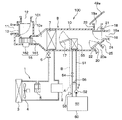
도 1은 일 실시 형태에 관련되는 차량용 공조 장치의 전체 구성을 도시한 도면이다.
도 2는 도 1의 차량용 공조 장치의 전기적 구성을 도시한 블록도이다.
도 3은 일 실시 형태에 관련되는 차량용 공조 장치의 작동 설명에 제공하는 도면이다.
도 4는 도 2의 공조 제어 장치가 실행하는 제어 처리를 도시한 흐름도이다.BRIEF DESCRIPTION OF DRAWINGS FIG. 1 is a diagram showing the overall configuration of a vehicle air conditioner according to an embodiment; FIG.
2 is a block diagram showing an electrical configuration of the automotive air conditioner of FIG.
Fig. 3 is a diagram provided for explaining an operation of a vehicle air conditioner according to an embodiment. Fig.
4 is a flowchart showing the control process executed by the air conditioning control apparatus of Fig.
이하, 일 실시 형태에 대하여 설명한다.Hereinafter, one embodiment will be described.
도 1, 도 2에 도시한 바와 같이, 차량용 공조 장치(100)는 주행용의 구동원인 내연 기관(이하, 엔진이라 한다)(50)으로부터 차량 주행용의 구동력을 얻는 차량에 탑재된다.As shown in Figs. 1 and 2, a
엔진(50)은 엔진(50)을 냉각하기 위한 엔진 냉각수가 순환하는 순환로(51)를 구비한다.The
순환로(51)에는 냉각수 펌프(52), 수온 센서(53), 전환 밸브(54) 및 히터 코어(55)가 배치된다. 냉각수 펌프(52)는 엔진 냉각수를 순환로(51) 내에서 순환시킨다. 수온 센서(53)는 엔진 냉각수의 온도를 검출하여, 그 온도에 따른 전기 신호를 출력한다. 전환 밸브(54)는 순환로(51)를 개폐하는 전환 장치이다.A
또한, 냉각수 펌프(52)는 전동기에 의해 구동된다. 그리고, 냉각수 펌프(52)의 전동기에 공급되는 전력 공급량이 엔진 제어 장치(57)에 의하여 제어됨으로써 순환로(51)를 순환하는 냉각수의 유량이 제어된다. 전환 밸브(54)는 전자 솔레노이드 또는 전동기로 구동되고, 엔진 제어 장치(57)에 의하여 제어된다. 또한, 수온 센서(53)는 예를 들면, 서미스터 등의 감온 소자가 사용되고, 수온 센서(53)로부터 출력되는 전기 신호는 엔진 제어 장치(57)에 입력된다.Further, the
순환로(51)에는 히터 코어(55)를 바이패스하여 엔진 냉각수를 순환시키는 바이패스로(56)가 접속된다. 구체적으로, 바이패스로(56)의 일단측은 순환로(51)에서의 엔진(50)과 전환 밸브(54)의 사이에 접속되고, 바이패스로(56)의 타단측은 순환로(51)에서의 엔진(50)과 히터 코어(55)의 사이에 접속되어 있다.A
그리고 전환 밸브(54)가 순환로(51)를 닫고 있을 때에는 부호 A를 붙인 파선 화살 표시로 나타내는 바와 같이, 엔진(50)으로부터 유출된 엔진 냉각수는 바이패스로(56)를 흐름으로써 히터 코어(55)를 바이패스하여 엔진(50)으로 되돌아간다.When the
한편, 전환 밸브(54)가 순환로(51)를 열고 있을 때에는 히터 코어(55)로의 엔진 냉각수의 흐름이 허용된다. 따라서, 이때에는 부호 B를 붙인 파선 화살 표시로 나타내는 바와 같이, 엔진(50)으로부터 유출된 엔진 냉각수는 히터 코어(55)를 지나서 엔진(50)으로 되돌아간다.On the other hand, when the
수온 센서(53)는 전환 밸브(54)가 순환로(51)를 닫고 있을 때 및 전환 밸브(54)가 순환로(51)를 열고 있을 때의 어느 때에도 엔진 냉각수가 흐르는 부위에 배치된다. 구체적으로, 수온 센서(53)는 엔진(50)과 바이패스로(56)의 상기 일단측의 사이에 배치된다.The
차량용 공조 장치(100)는 냉동 사이클(1), 공조 유닛(8) 및 공조 제어 장치(61) 등을 구비한다. 차량용 공조 장치(100)는 차실내를 공조하는 오토 에어컨 시스템이다. 즉, 차량용 공조 장치(100)는 차실내를 공조하는 공조 유닛(8)을 공조 제어 장치(61)에 의하여 제어하도록 구성된다.The vehicle
공조 유닛(8)은 차실내 최전방부의 인스트루먼트 패널(instrument panel)의 내측에 배치된다. 이 공조 유닛(8)은 차실내의 공기인 내기와 차실외의 공기인 외기의 한쪽 또는 양쪽을 흡입하고, 또한 그 흡입한 공기의 온도를 조절하여 차실내로 분출한다.The air conditioning unit 8 is disposed inside the instrument panel at the foremost part of the vehicle interior. The air conditioning unit 8 sucks one or both of the air inside the vehicle cabin and the outside air which is air outside the cabin, and also adjusts the temperature of the air sucked into the cabin and ejects the air into the cabin.
공조 유닛(8)은 증발기(7), 공조 케이스(10), 내외기 전환 도어(13), 송풍기(16), 에어믹스 도어(17), 복수의 분출구 전환 도어(21, 22) 및 히터 코어(55) 등을 가지고 있다. 또한, 증발기(7)는 이 공조 유닛(8)에 포함되고, 냉동 사이클(1)에도 포함된다.The air conditioning unit 8 includes an
공조 케이스(10)는 공조 유닛(8)의 하우징을 이루고, 공조 케이스(10)의 일측에는 공기 흡입구(11, 12)가 형성되고, 타측에는 차실내를 향하는 공기가 통과하는 복수의 분출구가 형성된다. 그리고, 공조 케이스(10)는, 그 공기 흡입구(11, 12)와 분출구의 사이에 송풍 공기가 통과하는 통풍로(10a)를 가진다.The
또한, 공조 케이스(10)는 2개의 공기 흡입구(11, 12)가 형성된 공기 흡입부(101)를 공조 케이스(10)의 상류측(즉, 일측)에 가지고 있다. 그 2개의 공기 흡입구(11, 12)의 한쪽은 내기를 흡입하는 내기 흡입구(11)이고, 다른쪽은 외기를 흡입하는 외기 흡입구(12)이다.The
내외기 전환 도어(13)는 내기 흡입구(11)의 개도와 외기 흡입구(12)의 개도를 증감하는 흡입구 개폐 장치이다. 내외기 전환 도어(13)는 공기 흡입부(101) 내에서 회전 이동 동작하고, 서보 모터(servo-motor) 등의 액추에이터에 의하여 구동된다. 상세하게는, 내외기 전환 도어(13)는 내기 흡입구(11)와 외기 흡입구(12)의 한쪽을 여는 만큼 다른 쪽을 닫도록 회전 이동하고, 공기 흡입부(101) 내에 유입되는 내기와 외기의 유량 비율을 조정한다. 또한, 내기 흡입구(11)의 개도란, 내기 흡입구(11)의 열림 정도이고, 외기 흡입구(12)의 개도란, 외기 흡입구(12)의 열림 정도이다.The inside / outside switching
송풍기(16)는 공기 흡입부(101)에 유입된 공기를 증발기(7)로 흘리고, 그 증발기(7)를 통과한 공기를 차실내로 유출시키도록 송풍한다. 그 때문에, 송풍기(16)는 원심식 팬인 임펠러(impeller)(161)와, 그 임펠러(161)에 연결된 송풍용 전동기(162)를 가지고 있다.The
송풍기(16)의 임펠러(161)는 공조 케이스(10) 내의 공기 흐름에 있어서, 공기 흡입부(101)보다도 하류측이고, 또한 증발기(7)보다도 상류측에 배치된다. 그리고 임펠러(161)는 복수의 팬 블레이드를 가지고, 공조 제어 장치(61)에 의하여 제어되는 송풍용 전동기(162)에 의해 회전 구동되어, 공조 케이스(10) 내에서 차실내를 향하는 공기류를 발생시킨다. 예를 들면, 송풍기(16)는 임펠러(161)의 회전수가 공조 제어 장치(61)에 의하여 제어됨으로써 각 분출구로부터 차실내를 향하여 각각 분출되는 공기의 풍량이 증감된다.The
증발기(7)는 공조 케이스(10) 내에서 송풍기(16)의 임펠러(161)에 대해 공기 흐름 하류측에 배치된다. 증발기(7)는 공기 냉각용의 열교환기이다. 즉, 증발기(7)는 팽창 밸브(6)에 의해 감압된 냉매와 송풍기(16)로부터 보내어지는 송풍 공기를 열교환시키고, 그 열교환에 의해 냉매를 증발 기화시키고, 또한 송풍 공기를 냉각한다.The
히터 코어(55)는 공조 케이스(10) 내에서 증발기(7)에 대해 공기 흐름 하류측에 배치되고, 또한 통풍로(10a)를 부분적으로 막도록 설치된다. 히터 코어(55)는 통풍로(10a)를 통과하는 송풍 공기를 엔진 냉각수와 열교환시킴으로써 가열한다.The
에어믹스 도어(17)는 히터 코어(55)에 대한 공기 흐름 상류측이고, 또한 증발기(7)에 대한 공기 흐름 하류측에 배치된다. 에어믹스 도어(17)는 서보 모터 등의 액추에이터에 의해 구동되고, 각 분출구로부터 차실내를 향하여 분출되는 공기의 온도를 변경한다. 바꾸어 말하면, 에어믹스 도어(17)는, 그 에어믹스 도어(17)의 회전 이동 위치에 따라서 증발기(7)를 통과하고, 히터 코어(55)를 우회하여 흐르는 냉풍과, 증발기(7)를 통과한 후에 히터 코어(55)를 통과하는 온풍의 풍량 비율을 조정한다.The
냉동 사이클(1)은 냉동 사이클(1)을 순환하는 냉매에 증발기(7)로 흡열시키고, 또한 콘덴서(3)로 방열시킨다. 냉동 사이클(1)은 압축기(2), 콘덴서(3), 리시버(5), 팽창 밸브(6), 증발기(7) 및 이들을 고리 모양으로 접속하는 냉매 배관 등으로 구성된다.The refrigeration cycle 1 absorbs heat to the refrigerant circulating in the refrigeration cycle 1 by the
압축기(2)는 엔진(50)에 대해 도시하지 않는 전자 클러치를 통하여 연결된다. 압축기(2)는 엔진(50)으로부터 구동력을 얻고, 냉매를 흡입하고, 압축하여 토출한다. 압축기(2)와 엔진(50)의 사이에 끼워진 전자 클러치의 단속(intermittence)은 공조 제어 장치(61)에 의하여 제어된다.The compressor (2) is connected to the engine (50) through an electromagnetic clutch (not shown). The compressor (2) obtains the driving force from the engine (50), sucks the refrigerant, compresses it and discharges it. The intermittence of the electromagnetic clutch sandwiched between the
콘덴서(3)는 엔진 룸 등의 차량이 주행할 때에 발생하는 주행풍을 받기 쉬운 장소에 설치된다. 콘덴서(3)에는 압축기(2)에서 압축된 냉매가 유입되고, 콘덴서(3)는, 그 압축된 냉매를 응축 액화시킨다. 즉, 콘덴서(3)는, 그 콘덴서(3)의 내부를 흐르는 냉매와 실외 팬(4)에 의해 송풍되는 외기 및 주행풍을 열교환시킨다.The
리시버(5)는 콘덴서(3)로부터 유출된 냉매에 포함되는 액상 냉매와 기상 냉매를 분리하는 것이다. 리시버(5)는, 그 분리한 액상 냉매를 팽창 밸브(6)로 유출시킨다.The receiver (5) separates the liquid refrigerant contained in the refrigerant discharged from the condenser (3) from the gaseous refrigerant. The receiver (5) causes the separated liquid refrigerant to flow out to the expansion valve (6).
팽창 밸브(6)는 리시버(5)로부터의 냉매를 감압 팽창시키고, 그 감압 팽창시킨 냉매를 증발기(7)로 유출시킨다. 그리고 증발기(7)는 팽창 밸브(6)로부터의 냉매를 증발 기화시킨다. 그 증발기(7)에서 증발 기화된 냉매는 압축기(2)에 흡입된다.The expansion valve (6) expands the refrigerant from the receiver (5) under reduced pressure and causes the refrigerant that has been decompressed and expanded to flow out to the evaporator (7). The evaporator (7) evaporates the refrigerant from the expansion valve (6). The refrigerant evaporated in the evaporator (7) is sucked into the compressor (2).
공조 케이스(10)에는 디프로스터(defroster) 개구부(18), 페이스(face) 개구부(19) 및 풋(foot) 개구부(20)가 형성되어 있고, 그들의 개구부(18, 19, 20)는 공조 케이스(10) 내의 공기 흐름에 있어서 가장 하류측의 부위에 배치된다.The
그리고 디프로스터 개구부(18)에는 디프로스터 덕트(23)가 접속되어 있고, 이 디프로스터 덕트(23)의 최하류단에는 디프로스터 분출구(18a)가 개구된다. 그 디프로스터 분출구(18a)는 차량의 프런트 창유리(49a)의 내면, 즉, 프런트 창유리(49a)의 내면을 향하여 주로 온풍을 분출한다.A defroster duct (23) is connected to the defroster opening (18), and a defroster air outlet (18a) is opened at the most downstream end of the defroster duct (23). The
페이스 개구부(19)에는 페이스 덕트(24)가 접속되어 있고, 이 페이스 덕트(24)의 최하류단에는 페이스 분출구(19a)가 개구된다. 그 페이스 분출구(19a)는 탑승자의 두흉부(head and chest)를 향하여 주로 냉풍을 분출한다.A
또한, 풋 개구부(20)에는 풋 덕트(25)가 접속되어 있고, 이 풋 덕트(25)의 최하류단에는 탑승자의 발밑부(foot)를 향하여 주로 온풍을 분출하는 풋 분출구(20a)가 개구된다.A
각 개구부(18, 19, 20)의 내측에는 2개의 분출구 전환 도어(21, 22)가 회전 이동 가능하게 부착된다. 2개의 분출구 전환 도어(21, 22)는 서보 모터 등의 액추에이터에 의해 각각 구동된다. 그리고 그 2개의 분출구 전환 도어(21, 22)는 공조 유닛(8)의 분출구 모드를 페이스 모드와 바이레벨(bi-level) 모드와 풋 모드와 풋 디프로스터 모드와 디프로스터 모드로 택일적으로 전환하는 것이 가능하다.Two air outlet switching doors (21, 22) are rotatably attached to the inside of the respective openings (18, 19, 20). The two
다음으로, 차량용 공조 장치(100)의 전기적 구성에 관하여 설명한다. 도 2에 도시한 바와 같이, 공조 제어 장치(61)에는 차실내 전면에 설치된 조작 패널(70) 상의 각 스위치로부터의 스위치 신호, 각 센서로부터의 센서 신호 및 엔진 제어 장치(57)로부터 출력되는 통신 신호 등이 입력된다.Next, the electrical configuration of the
여기에서, 조작 패널(70)에 관하여 설명한다. 조작 패널(70)은 인스트루먼트 패널에 일체적으로 설치된다. 조작 패널(70)은 도시는 생략하지만, 예를 들면, 액정 디스플레이, 내외기 전환 스위치, 디프로스터 스위치, 분출 모드 전환 스위치, 분출 풍량 전환 스위치, 오토 스위치, 온도 설정 스위치 및 에어컨 스위치(70a) 등을 포함하여 구성된다.Here, the
액정 디스플레이에는 설정 온도, 분출 모드 및 분출 풍량 등을 시각 표시하는 표시 영역이 설치된다. 또한, 액정 디스플레이에는 예를 들면, 외기 온도, 흡입 모드 및 시각 등을 시각 표시하는 표시 영역이 설치될 수 있다.The liquid crystal display is provided with a display area for displaying a set temperature, an ejection mode, and an ejection air amount, etc., in a time display. Further, the liquid crystal display may be provided with a display area for displaying the outside air temperature, the suction mode and the time, for example.
조작 패널(70)의 각종 스위치에 관하여 설명한다. 디프로스터 스위치는 분출 모드를 디프로스터 모드로 설정하여 프런트 창유리(49a)의 김서림 방지 능력을 올리는 것을 지령하는 스위치이다. 모드 전환 스위치는 탑승자의 매뉴얼 조작에 따라서 분출 모드를 페이스 모드, 바이레벨 모드, 풋 모드, 풋 디프로스터 모드 중 어느 하나로 설정하도록 요구하는 스위치이다. 온도 설정 스위치는 온도를 원하는 온도로 설정하기 위한 스위치이다.Various switches of the
또한, 에어컨 스위치(70a)는 냉동 사이클(1)의 압축기(2)의 가동 또는 정지를 지령하는 스위치이다. 그리고 이그니션(ignition) 온(on) 시에 있어서 에어컨 스위치(70a)가 온으로 전환된 경우에, 공조 유닛(8)은 증발기(7)에서 냉각된 공기 또는 증발기(7)에서 냉각된 후에 히터 코어(55)에서 가열된 공기를 차실내로 분출하는 공조 운전을 실시한다. 또한, 오토 스위치는 차실내를 자동적으로 공조하는 오토 에어컨 제어의 실행을 지령하는 스위치이다.The
공조 제어 장치(61)의 내부에는 도시는 생략하지만, 연산 처리나 제어 처리를 실시하는 CPU(즉, 중앙 연산 장치), ROM이나 RAM 등의 메모리 및 I/O포트(즉, 입력/출력 회로) 등의 기능을 포함하여 구성되는 주지의 마이크로컴퓨터가 설치된다. ROM 및 RAM은 모두 비천이적 실체적 기억 매체이다. 각종 센서로부터의 센서 신호가 I/O포트 또는 A/D변환 회로에 의하여 A/D변환된 후에 마이크로컴퓨터에 입력된다.Although not shown in the drawing, the air
공조 제어 장치(61)에는 차실내에서의 운전석 주위의 공기 온도인 내기 온도를 검출하는 내기 센서(71) 및 차실외 온도인 외기 온도를 검출하는 외기 센서(72)가 접속된다.The air
내기 센서(71) 및 외기 센서(72)는 예를 들면, 서미스터 등의 감온 소자가 사용되고 있다. 내기 센서(71)는 운전석 부근(예를 들면, 스티어링 휠 부근의 인스트루먼트 패널 내부)의 운전석 이외의 분출구를 닫아도 거의 영향받지 않는 부위에 설정된다.For the
또한, 공조 제어 장치(61)에는 이그니션 스위치(73)가 접속되어 있고, 그 이그니션 스위치(73)의 스위치 위치를 나타내는 스위치 전환 신호도 입력된다. 그 이그니션 스위치(73)는 운전석의 근처에 설치되어 탑승자가 조작하는 스위치이고, 엔진(50)의 운전에 대한 허가와 비허가를 전환하기 위한 주지의 스위치이다. 예를 들면, 이그니션 스위치(73)의 온은 엔진(50)의 운전을 허가하는 스위치 전환 상태이고, 이그니션 스위치(73)의 오프(off)는 엔진(50)의 운전을 비허가로 하고, 또한 오디오 등의 사전에 결정된 액세서리 기기를 오프로 하는 스위치 전환 상태이다. 따라서, 탑승자는 차량의 사용을 끝낸 경우에는, 이그니션 스위치(73)를 오프로 전환한다.An
또한, 공조 제어 장치(61)에는 엔진 제어 장치(57)로부터 출력되는 통신 신호 등이 입력된다. 구체적으로는, 순환로(51)를 순환하는 냉각수의 유량에 관한 정보, 수온 센서(53)에서 검출한 엔진 냉각수 온도에 관한 정보 및 전환 밸브(54)의 작동 상태에 관한 정보 등이 입력된다. 또한, 엔진 제어 장치(57)는 냉각수 펌프(52)의 전동기에 공급되는 전력 공급량에 기초하여 순환로(51)를 순환하는 냉각수의 유량을 산출한다.A communication signal or the like output from the
다음으로, 엔진 제어 장치(57)가 실행하는 엔진 냉각수 제어 처리에 대하여 설명한다.Next, the engine cooling water control process executed by the
우선, 엔진(50)이 시동되면, 엔진 제어 장치(57)로부터의 제어 신호를 받아서 전환 밸브(54)는 순환로(51)를 닫는다. 또한, 엔진 제어 장치(57)로부터의 제어 신호를 받아서, 냉각수 펌프(52)는 엔진 냉각수를 순환로(51) 내에서 순환시킨다.First, when the
그리고, 전환 밸브(54)가 순환로(51)를 닫고 있을 때에는, 엔진(50)으로부터 유출된 엔진 냉각수는 바이패스로(56)를 흐름으로써 히터 코어(55)를 바이패스하여 엔진(50)으로 되돌아간다.When the switching
이하, 전환 밸브(54)가 순환로(51)를 닫고 있을 때의 냉각수 회로 모드를 제 1 모드라 한다. 또한, 순환로(51)에서, 제 1 모드인 때에 엔진 냉각수가 흐르는 냉각수 회로를 엔진측 냉각수 회로라 한다. 또한, 순환로(51)에서, 제 1 모드인 때에 엔진 냉각수가 흐르지 않는 냉각수 회로를 히터 코어측 회로라 한다.Hereinafter, the cooling water circuit mode when the switching
여기에서, 도 3에서 파선은 수온 센서(53)에서 검출한 엔진 냉각수의 온도, 즉, 엔진측 냉각수 회로의 엔진 냉각수의 온도를 나타내고 있다. 이 도 3에 도시한 바와 같이, 엔진(50)의 시동 후, 시간의 경과에 따라서 엔진측 냉각수 회로의 엔진 냉각수의 온도가 상승하고, 그 엔진 냉각수의 온도가 설정 온도에 도달하면, 엔진 제어 장치(57)로부터의 제어 신호를 받아서 전환 밸브(54)는 순환로(51)를 연다.3, the broken line indicates the temperature of the engine cooling water detected by the
그리고 전환 밸브(54)가 순환로(51)를 열고 있을 때에는, 엔진(50)으로부터 유출된 엔진 냉각수는 히터 코어측 회로에도 흐르고, 히터 코어(55)를 지나서 엔진(50)으로 되돌아간다. 이하, 전환 밸브(54)가 순환로(51)를 열고 있을 때의 냉각수 회로 모드를 제 2 모드라 한다.When the switching
다음으로, 공조 제어 장치(61)가 실행하는 제어 처리에 대하여, 도 3, 도 4를 기초해서 설명한다. 또한, 도 3에서 일점쇄선은 히터 코어(55)의 온도를 나타내고, 도 3에서 실선은 제어용 수온 데이터를 나타내고 있다.Next, the control processing executed by the air
공조 제어 장치(61)는 이하 상세히 서술하는 바와 같이, 이 제어 처리에 있어서, 제어용 수온 데이터를 산출하고, 그 제어용 수온 데이터에 기초하여 송풍기(16) 등의 공조 제어 기기의 작동을 제어하게 된다.The air
공조 제어 장치(61)는 차량의 이그니션 스위치(73)가 온으로 전환되고, 또한 에어컨 스위치(70a)가 온으로 전환된 경우에, 도 4의 흐름도에 도시한 제어 처리를 주기적으로 반복 실행한다. 따라서, 도 4의 제어 처리는 공조 유닛(8)의 공조 운전의 실행 중에 그 공조 운전과 병렬적으로 실행된다. 즉, 도 4의 제어 처리는 공조 유닛(8)의 공조 운전에 관한 다른 제어 처리, 예를 들면, 오토 에어컨 제어에 포함되는 제어 처리와 병렬적으로 실행되는 것이다.The air
우선, 도 4의 단계 S101에서 공조 제어 장치(61)는 엔진 제어 장치(57)로부터 출력되는 전환 밸브(54)의 작동 상태에 관한 정보에 기초하여 냉각수 회로 모드가 제 1 모드인지의 여부를 판정한다.4, the air
엔진(50)의 시동 직후와 같이, 수온 센서(53)에서 검출한 엔진 냉각수의 온도가 설정 온도 미만의 저온역인 때에는 전환 밸브(54)가 순환로(51)를 닫고 있어서 제 1 모드가 설정되어 있기 때문에, 이 단계 S101에서 긍정 판정되고, 단계 S102로 진행한다.When the temperature of the engine cooling water detected by the
단계 S102에서는 엔진 제어 장치(57)로부터 출력되는 수온 센서(53)에서 검출한 엔진 냉각수에 관한 정보에 기초하여 히터 코어(55)의 추정 온도(이하, 히터 코어 추정 온도라 한다)를 산출한다.In step S102, the estimated temperature of the heater core 55 (hereinafter referred to as the heater core estimated temperature) is calculated based on the information on the engine cooling water detected by the
구체적으로, 냉간 시동 시에는 수온 센서(53)에서 검출한 엔진 냉각수의 온도와 히터 코어(55)의 온도는 대략 동등하기 때문에 엔진(50)을 시동했을 때에 수온 센서(53)에서 검출한 엔진 냉각수의 온도를 히터 코어 추정 온도로 한다. 이에 따르면, 히터 코어 추정 온도와 실제의 히터 코어(55)의 온도의 차이를 작게 할 수 있다.Specifically, at the time of cold start, the temperature of the engine cooling water detected by the
이어서, 단계 S102에서 단계 S103으로 진행한다. 이 단계 S103에서는 제어용 수온 데이터를 산출한다. 구체적으로는, 제 1 모드가 설정되어 있어서 단계 S101에서 긍정 판정되어 있는 경우에는, 단계 S102에서 산출한 히터 코어 추정 온도를 제어용 수온 데이터로 한다. 또한, 단계 S102 및 단계 S103은 제 1 수온 데이터 산출부를 구성한다.Subsequently, the process proceeds from step S102 to step S103. In this step S103, control water temperature data is calculated. Specifically, when the first mode is set and an affirmative determination is made in step S101, the heater core estimated temperature calculated in step S102 is used as control water temperature data. In addition, steps S102 and S103 constitute a first water temperature data calculation unit.
이어서, 단계 S103에서 단계 S104로 진행한다. 제어부로서의 단계 S104에서는 송풍기(16) 등의 공조 제어 기기의 작동 목표값을 단계 S103에서 산출한 제어용 수온 데이터에 기초하여 산출하고, 산출한 작동 목표값에 대응하는 제어 신호를 공조 제어 기기에 출력한다. 또한, 송풍기(16) 이외의 공조 제어 기기로서는, 내외기 전환 도어(13), 에어믹스 도어(17), 분출구 전환 도어(21, 22)를 포함할 수 있다.Subsequently, the process proceeds from step S103 to step S104. In step S104 as the control unit, an operation target value of the air conditioning control device such as the
상기와 같이 하여 제 1 모드가 설정되어 있는 동안의 제어용 수온 데이터를 산출함으로써 도 3에 도시한 바와 같이, 제 1 모드가 설정되어 있는 동안의 제어용 수온 데이터와 실제의 히터 코어(55)의 온도의 차이를 작게 할 수 있다. 따라서, 제 1 모드가 설정되어 있는 동안의 풍량이나 분출 공기 온도 등의 제어가 적절히 실시되어 쾌적성이 향상된다.3, the control water temperature data while the first mode is being set and the actual temperature of the
한편, 제 1 모드가 설정되어 있는 상태에서 엔진(50)이 운전되어, 수온 센서(53)에서 검출한 엔진 냉각수의 온도가 설정 온도에 도달하면, 전환 밸브(54)가 순환로(51)를 열어서 제 2 모드로 전환되기 때문에 단계 S101에서 부정 판정되어 단계 S105로 진행한다.On the other hand, when the
그리고, 제 1 모드로부터 제 2 모드로 전환되었을 때에는 단계 S105에서 긍정 판정되고, 단계 S106으로 진행한다.When the mode is switched from the first mode to the second mode, an affirmative determination is made in step S105, and the process proceeds to step S106.
단계 S106에서는 제어용 수온 데이터로서 후술하는 억제 수온을 이용하는 시간, 즉, 목표 억제 시간(T)을 산출한다.In step S106, the time for using the suppression water temperature to be described later, that is, the target suppression time T, is calculated as the control water temperature data.
이 목표 억제 시간(T)은 도 3에 도시한 바와 같이, 제 2 모드로 전환되고나서 히터 코어(5)의 온도와 수온 센서(53)에서 검출한 엔진 냉각수의 온도가 대략 동등해지기까지의 시간(이하, 등온화 시간이라 한다)에 상당한다.As shown in Fig. 3, the target suppression time T is a time period from the switching to the second mode until the temperature of the
구체적으로, 목표 억제 시간(T)은 이하와 같이 하여 산출한다. 또한, 목표 억제 시간(T)은 본 개시의 사전에 결정된 시간에 상당한다.Specifically, the target suppression time T is calculated as follows. Further, the target suppression time T corresponds to a predetermined time of the present disclosure.
우선, 제 2 모드로 전환되었을 때의 히터 코어(55)의 온도는 단계 S103에서 산출한 제어용 수온 데이터와 대략 동등하다. 그리고, 제 2 모드로 전환되었을 때의 히터 코어(55)의 온도와 제 2 모드로 전환되었을 때의 수온 센서(53)에서 검출한 엔진 냉각수의 온도의 차가 클수록 등온화 시간은 길어진다.First, the temperature of the
그래서, 단계 S103에서 산출한 제어용 수온 데이터와, 제 2 모드로 전환되었을 때에 수온 센서(53)에서 검출한 엔진 냉각수의 온도의 차가 클수록 목표 억제 시간(T)을 길게 한다. 이에 따라, 히터 코어(55)의 온도와 수온 센서(53)에서 검출한 엔진 냉각수의 온도가 대략 동등해지는 타이밍과, 목표 억제 시간(T)이 종료되는 타이밍의 차이를 작게 할 수 있다.Thus, the larger the difference between the control water temperature data calculated in step S103 and the temperature of the engine cooling water detected by the
또한, 순환로(51)를 순환하는 냉각수의 유량이 적을수록 등온화 시간은 길어진다. 그래서 엔진 제어 장치(57)로부터 출력되는 순환로(51)를 순환하는 냉각수의 유량에 관한 정보에 기초하여, 순환로(51)를 순환하는 냉각수의 유량이 적을수록 목표 억제 시간(T)을 길게 한다. 이에 따라, 히터 코어(55)의 온도와 수온 센서(53)에서 검출한 엔진 냉각수의 온도가 대략 동등해지는 타이밍과, 목표 억제 시간(T)이 종료되는 타이밍의 차이를 작게 할 수 있다.In addition, the smaller the flow rate of the cooling water circulating through the
또한, 송풍기(16)에 의한 송풍량이 많을수록 엔진 냉각수로부터의 흡열량이 커져서, 엔진 냉각수의 온도 상승이 완만해진다. 그래서, 송풍기(16)의 회전수에 기초하여 송풍기(16)에 의한 송풍량을 산출하고, 송풍기(16)에 의한 송풍량이 많을수록 목표 억제 시간(T)을 길게 한다. 이에 따라, 히터 코어(55)의 온도와 수온 센서(53)에서 검출한 엔진 냉각수의 온도가 대략 동등해지는 타이밍과, 목표 억제 시간(T)이 종료되는 타이밍의 차이를 작게 할 수 있다.Further, the larger the blowing amount by the
또한, 내기를 히터 코어(55)에서 가열하여 차실내로 송풍하는 내기 모드인 때에는 내기 온도가 낮을수록 엔진 냉각수로부터의 흡열량이 커져서, 엔진 냉각수의 온도 상승이 완만해진다. 그래서, 내기 모드인 때에는 내기 센서(71)에서 검출한 내기 온도가 낮을수록 목표 억제 시간(T)을 길게 한다. 이에 따라, 히터 코어(55)의 온도와 수온 센서(53)에서 검출한 엔진 냉각수의 온도가 대략 동등해지는 타이밍과, 목표 억제 시간(T)이 종료되는 타이밍의 차이를 작게 할 수 있다.Further, when the inside air is heated by the
또한, 외기를 히터 코어(55)에서 가열하여 차실내로 송풍하는 외기 모드인 때에는 외기 온도가 낮을수록 엔진 냉각수로부터의 흡열량이 커져서, 엔진 냉각수의 온도 상승이 완만해진다. 그래서, 외기 모드인 때에는 외기 센서(72)에서 검출한 외기 온도가 낮을수록 목표 억제 시간(T)을 길게 한다. 이에 따라, 히터 코어(55)의 온도와 수온 센서(53)에서 검출한 엔진 냉각수의 온도가 대략 동등해지는 타이밍과, 목표 억제 시간(T)이 종료되는 타이밍의 차이를 작게 할 수 있다.Further, when the outside air is heated in the
이어서, 단계 S106에서 단계 S107로 진행한다. 이 단계 S107에서는 제 2 모드로 전환되고나서의 경과 시간인 억제 시간을 계측하기 위해, 억제 시간의 타이머를 클리어하여 0으로 한다.Then, the process proceeds from step S106 to step S107. In this step S107, the timer of the suppression time is cleared to 0 to measure the suppression time which is the elapsed time since switching to the second mode.
이어서, 단계 S107에서 단계 S108로 진행한다. 이 단계 S108에서는 억제 수온을 산출한다. 구체적으로, 억제 수온은 수온 센서(53)에서 검출한 엔진 냉각수의 온도보다도 낮은 온도로 설정된다. 보다 상세하게는, 단계 S103에서 산출한 제어용 수온 데이터를 억제 수온으로 한다. 이 억제 수온은 엔진 냉각수의 온도가 크게 변동하고 있는 동안, 제어용 수온 데이터의 변동을 방지하기 위해 이용한다.Subsequently, the process proceeds from step S107 to step S108. In this step S108, the suppression water temperature is calculated. Specifically, the suppression water temperature is set to a temperature lower than the temperature of the engine cooling water detected by the
이어서, 단계 S108에서 단계 S109로 진행한다. 이 단계 S109에서는 억제 시간이 목표 억제 시간(T)을 넘었는지의 여부를 판정한다. 그리고 억제 시간이 목표 억제 시간(T) 이하인 경우에는, 단계 S109에서 부정 판정되어 단계 S110으로 진행한다.Then, the process proceeds from step S108 to step S109. In this step S109, it is determined whether or not the suppression time exceeds the target suppression time (T). If the suppression time is less than or equal to the target suppression time T, a negative determination is made in step S109 and the process proceeds to step S110.
단계 S110에서는 제어용 수온 데이터를 산출한다. 구체적으로는, 억제 시간이 목표 억제 시간(T) 이하이고, 단계 S109에서 부정 판정되어 있는 경우에는, 단계 S108에서 산출한 억제 수온을 제어용 수온 데이터로 한다. 여기에서, 단계 S108에서 산출한 억제 수온은 단계 S103에서 산출한 제어용 수온 데이터와 같다. 따라서, 도 3에 도시한 바와 같이, 제 1 모드가 설정되어 있는 동안의 제어용 수온 데이터와, 억제 시간이 목표 억제 시간(T) 이하인 때의 제어용 수온 데이터는 동등해져 있다. 또한, 단계 S106, 단계 S108 및 단계 S110은 제 2 수온 데이터 산출부를 구성한다.In step S110, control water temperature data is calculated. Specifically, when the suppression time is equal to or less than the target suppression time T and the negative determination is made in step S109, the suppression water temperature calculated in step S108 is used as control water temperature data. Here, the suppression water temperature calculated in step S108 is the same as the control water temperature data calculated in step S103. Therefore, as shown in Fig. 3, the control water temperature data during the first mode is equal to the control water temperature data when the suppression time is equal to or less than the target suppression time T. In addition, steps S106, S108, and S110 constitute a second water temperature data calculation unit.
이어서, 단계 S110에서 단계 S111로 진행한다. 이 단계 S111에서는 억제 시간을 계측하기 위해, 억제 시간을 카운트 업한다. 이에 따라, 억제 시간의 값이 1카운트만큼 증가한다.Subsequently, the process proceeds from step S110 to step S111. In this step S111, the suppression time is counted up to measure the suppression time. Thereby, the value of the suppression time increases by one count.
이어서, 단계 S111에서 단계 S104로 진행한다. 단계 S104에서는 송풍기(16) 등의 공조 제어 기기의 작동 목표값을 단계 S110에서 산출한 제어용 수온 데이터에 기초하여 산출하고, 산출한 작동 목표값에 대응하는 제어 신호를 공조 제어 기기로 출력한다.Then, the process proceeds from step S111 to step S104. In step S104, the operation target value of the air conditioning control device such as the
다음으로, 제 2 모드에서의 엔진(50)의 운전이 계속되고 있는 경우에는, 단계 S105에서 부정 판정되어 단계 S109로 진행한다.Next, when the operation of the
그리고, 억제 시간이 목표 억제 시간(T) 이하인 경우에는, 단계 S110 및 단계 S111을 거쳐서 단계 S104로 진행하고, 단계 S104에서는 상기한 바와 같이 제어 신호를 공조 제어 기기로 출력한다.If the suppression time is equal to or less than the target suppression time T, the process proceeds to step S104 through steps S110 and S111, and in step S104, the control signal is output to the air conditioning control device as described above.
상기와 같이, 제 2 모드로 전환되고나서 목표 억제 시간(T)이 경과하는 동안에는 수온 센서(53)에서 검출한 엔진 냉각수의 온도보다도 낮은 온도를 제어용 수온 데이터로 함으로써 제어용 수온 데이터와 실제의 히터 코어(55)의 온도의 차이를 작게 할 수 있다. 따라서, 풍량이나 분출 공기 온도 등의 제어가 적절하게 실시되어 쾌적성이 향상된다.As described above, the temperature lower than the temperature of the engine cooling water detected by the
또한, 제 2 모드로 전환되고나서 목표 억제 시간(T)이 경과하는 동안에는, 제어용 수온 데이터의 변동이 억제됨으로써 풍량의 변동이나 각종 제어의 헌팅이 억제된다.Further, while the target suppression time T elapses after the mode is switched to the second mode, the variation of the control water temperature data is suppressed, so that the fluctuation of the air volume and hunting of various controls are suppressed.
한편, 억제 시간이 목표 억제 시간(T)을 넘은 경우에는, 단계 S109에서 긍정 판정되어 단계 S112로 진행한다.On the other hand, if the suppression time has exceeded the target suppression time T, the determination in step S109 is affirmative and the process proceeds to step S112.
단계 S112에서는 제어용 수온 데이터를 산출한다. 억제 시간이 목표 억제 시간(T)을 넘은 경우에는, 히터 코어(55)의 온도와 수온 센서(53)에서 검출한 엔진 냉각수의 온도가 대략 동등해져 있다고 추정된다. 따라서, 단계 S112에서는 수온 센서(53)에서 검출한 엔진 냉각수의 온도를 제어용 수온 데이터로 한다.In step S112, control water temperature data is calculated. It is estimated that the temperature of the
이어서, 단계 S112에서 단계 S104로 진행하고, 단계 S104에서는 송풍기(16) 등의 공조 제어 기기의 작동 목표값을 단계 S112에서 산출한 제어용 수온 데이터에 기초하여 산출하고, 산출한 작동 목표값에 대응하는 제어 신호를 공조 제어 기기로 출력한다.Subsequently, the process proceeds from step S112 to step S104. In step S104, the operation target value of the air conditioning control device such as the
본 실시 형태에 따르면, 제 1 모드가 설정되어 있는 동안에는, 엔진(50)을 시동했을 때에 수온 센서(53)에서 검출한 엔진 냉각수의 온도에 기초하여 제어용 수온 데이터를 산출함으로써 제어용 수온 데이터와 실제의 히터 코어(55)의 온도의 차이를 작게 할 수 있다. 따라서, 풍량이나 분출 공기 온도 등의 제어가 적절하게 실시되어 쾌적성이 향상된다.According to the present embodiment, while the first mode is being set, the control water temperature data is calculated based on the temperature of the engine cooling water detected by the
또한, 제 2 모드로 전환되고나서 목표 억제 시간(T)이 경과하는 동안에는, 수온 센서(53)에서 검출한 엔진 냉각수의 온도보다도 낮은 온도를 제어용 수온 데이터로 함으로써 제어용 수온 데이터와 실제의 히터 코어(55)의 온도의 차이를 작게 할 수 있다. 따라서, 풍량이나 분출 공기 온도 등의 제어가 적절하게 실시되어 쾌적성이 향상된다.Further, during the elapse of the target suppression time T after switching to the second mode, the temperature lower than the temperature of the engine cooling water detected by the
또한, 제 2 모드로 전환되고나서 목표 억제 시간(T)이 경과하는 동안에는, 제어용 수온 데이터의 변동이 억제됨으로써 풍량의 변동이나 각종 제어의 헌팅이 억제된다.Further, while the target suppression time T elapses after the mode is switched to the second mode, the variation of the control water temperature data is suppressed, so that the fluctuation of the air volume and hunting of various controls are suppressed.
(변형예 1) 상기 실시 형태의 단계 S102에서 공조 제어 장치(61)는 엔진(50)을 시동했을 때에 수온 센서(53)에서 검출한 엔진 냉각수의 온도를 히터 코어 추정 온도로 했다. 그러나 이에 대신하여, 공조 제어 장치(61)는 단계 S102에서는 엔진(50)을 시동했을 때에 수온 센서(53)에서 검출한 엔진 냉각수의 온도를 보정하여, 보정 후의 온도를 히터 코어 추정 온도로 할 수 있다. 공조 제어 장치(61)는, 이 보정을, 엔진(50)을 시동했을 때에 외기 센서(72)에서 검출한 외기의 온도가 높을수록 보정 후의 온도가 높아지도록 실시한다.(Modification 1) In step S102 of the above embodiment, the air
(변형예 2) 공조 제어 장치(61)는 상기 실시 형태의 단계 S108에서는 단계 S103에서 산출한 제어용 수온 데이터를 억제 수온으로 했다. 그러나 공조 제어 장치(61)는 이에 대신하여, 단계 S108에서는 단계 S103에서 산출한 제어용 수온 데이터를 제 2 모드로 전환하고나서의 시간 경과에 따라서 커지도록 보정할 수 있다. 그리고 공조 제어 장치(61)는, 그 보정 후의 제어용 수온 데이터를 억제 수온으로 할 수 있다. 다만, 이 변형예의 경우에도, 억제 수온은 수온 센서(53)에서 검출한 엔진 냉각수의 온도보다도 낮은 온도로 설정된다.(Variation 2) The air
(변형예 3) 변형예 2에 있어서, 공조 제어 장치(61)는 순환로(51)를 순환하는 엔진 냉각수의 유량이 적을수록 제어용 수온 데이터의 값의 시간당 변화량을 작게 할 수 있다.(Modification 3) In Modified Example 2, the air
(변형예 4) 변형예 2에 있어서, 공조 제어 장치(61)는 송풍기(16)에 의한 송풍량이 많을수록 제어용 수온 데이터의 값의 시간당 변화량을 작게 할 수 있다.(Modification 4) In Modified Example 2, the air
(변형예 5) 변형예 2에 있어서, 공조 제어 장치(61)는 내기 모드인 때에는 내기 센서(71)에서 검출한 내기 온도가 낮을수록 제어용 수온 데이터의 값의 시간당 변화량을 작게 할 수 있다.(Modification 5) In Modified Example 2, in the air-conditioning mode, the air
(변형예 6) 변형예 2에 있어서, 공조 제어 장치(61)는 외기 모드인 때에는 외기 센서(72)에서 검출한 외기 온도가 낮을수록 제어용 수온 데이터의 값의 시간당 변화량을 작게 할 수 있다.(Modification 6) In Modified Example 2, in the air
(다른 실시 형태)(Other Embodiments)
또한, 본 개시는 상기한 실시 형태에 한정되는 것은 아니고, 적절히 변경이 가능하다.Note that the present disclosure is not limited to the above-described embodiment, and can be appropriately changed.
또한, 상기 실시 형태에 있어서, 실시 형태를 구성하는 요소는 특별히 필수라고 명시한 경우 및 원리적으로 명백히 필수라고 생각되는 경우 등을 제외하고, 반드시 필수는 아니다.In addition, in the above-described embodiment, the elements constituting the embodiment are not necessarily essential except when it is stated that they are particularly necessary, and in cases where they are considered to be essential in principle.
또한, 상기 실시 형태에 있어서, 실시 형태의 구성 요소의 개수, 수치, 양, 범위 등의 수치가 언급되어 있는 경우, 특별히 필수라고 명시한 경우 및 원리적으로 명백히 특정한 수에 한정되는 경우 등을 제외하고, 그 특정한 수에 한정되는 것은 아니다.In addition, in the above-described embodiments, the numerical values such as the number, numerical value, amount and range of the constituent elements of the embodiment are mentioned, except for cases where it is specifically stated as essential, and in principle, , But is not limited to the specific number.
또한, 상기 실시 형태에 있어서, 구성 요소 등의 형상, 위치 관계 등에 언급할 때는, 특별히 명시한 경우 및 원리적으로 특정한 형상, 위치 관계 등에 한정되는 경우 등을 제외하고, 그 형상, 위치 관계 등에 한정되는 것은 아니다.In addition, in the above-described embodiment, when referring to the shape, positional relationship, and the like of constituent elements and the like, they are limited to shapes and positional relationships except for cases specifically specified and in principle limited to specific shapes and positional relationships It is not.
또한, 상기 실시 형태 및 변형예는 조합이 명백히 불가능한 경우를 제외하고, 적절히 조합이 가능하다.Furthermore, the above-described embodiment and modifications can be combined appropriately, except where the combination is clearly impossible.
Claims (14)
상기 차실내로 공기를 송풍하는 송풍기(16)와,
내연 기관(50)을 냉각하기 위한 냉각수가 순환하는 순환로(51)와,
상기 순환로에 배치되어, 냉각수에 의해 상기 차실내로 송풍되는 공기를 가열하는 히터 코어(55)와, 상기 순환로에 접속되어, 상기 히터 코어를 바이패스해서 냉각수를 순환시키는 바이패스로(56)와,
상기 내연 기관으로부터 유출된 냉각수가 상기 바이패스로를 흐름으로써 상기 히터 코어를 바이패스하여 상기 내연 기관으로 되돌아가는 제 1 모드 및 상기 내연 기관으로부터 유출된 냉각수가 상기 히터 코어에 흐르는 제 2 모드를 전환 설정하는 전환 장치(54)와,
상기 순환로 내에, 상기 제 1 모드 및 상기 제 2 모드의 어느 때에도 냉각수가 흐르는 부위에서 냉각수의 온도를 검출하는 수온 센서(53)와,
제어용 수온 데이터에 기초하여 상기 송풍기의 작동을 제어하는 제어부(S104)와,
상기 제 1 모드인 때의 상기 제어용 수온 데이터를 산출하는 제 1 수온 데이터 산출부(S102, S103)와,
상기 제 2 모드로 전환되고나서 사전에 결정된 시간이 경과하는 동안의 상기 제어용 수온 데이터를 산출하는 제 2 수온 데이터 산출부(S106, S108, S110)를 구비하고,
상기 제 1 수온 데이터 산출부는 상기 내연 기관이 시동되었을 때에 상기 수온 센서에서 검출된 냉각수의 온도에 기초하여 상기 제어용 수온 데이터를 산출하고,
상기 제 2 수온 데이터 산출부는 상기 수온 센서에서 검출한 냉각수의 온도보다도 낮은 온도를 상기 제어용 수온 데이터로 하는
차량용 공조 장치.
A vehicle air conditioning system for performing air conditioning in a car interior,
An air blower (16) for blowing air into the vehicle interior,
A circulation path (51) through which cooling water for cooling the internal combustion engine (50) circulates,
A heater core 55 disposed in the circulation path for heating the air blown into the car by the cooling water, a bypass path 56 connected to the circulation path for bypassing the heater core to circulate the cooling water, ,
A first mode in which cooling water flowing out of the internal combustion engine flows through the bypass path to return to the internal combustion engine by bypassing the heater core and a second mode in which cooling water flowing out of the internal combustion engine flows into the heater core A switching device 54 for setting,
A water temperature sensor (53) for detecting the temperature of the cooling water in a region where the cooling water flows in either of the first mode and the second mode,
A control unit (S104) for controlling the operation of the blower based on the control water temperature data,
A first water temperature data calculation unit (S102, S103) for calculating the control water temperature data in the first mode,
And a second water temperature data calculation unit (S106, S108, S110) for calculating the control water temperature data during a lapse of a predetermined time after switching to the second mode,
The first water temperature data calculation unit calculates the control water temperature data based on the temperature of the cooling water detected by the water temperature sensor when the internal combustion engine is started,
Wherein the second water temperature data calculation unit uses a temperature lower than the temperature of the cooling water detected by the water temperature sensor as the control water temperature data
Automotive air conditioning system.
상기 제 1 수온 데이터 산출부는 상기 내연 기관이 시동되었을 때에 상기 수온 센서에서 검출된 냉각수의 온도를 상기 제어용 수온 데이터로 하는
차량용 공조 장치.
The method according to claim 1,
Wherein the first water temperature data calculation unit uses the temperature of the cooling water detected by the water temperature sensor as the control water temperature data when the internal combustion engine is started
Automotive air conditioning system.
외기의 온도를 검출하는 외기 센서(72)를 구비하고,
상기 제 1 수온 데이터 산출부는 상기 내연 기관이 시동되었을 때에 상기 수온 센서에서 검출된 냉각수의 온도를, 상기 내연 기관이 시동되었을 때에 상기 외기 센서에서 검출된 외기의 온도가 높은만큼, 높아지도록 보정하여, 상기 제어용 수온 데이터로 하는
차량용 공조 장치.
The method according to claim 1,
And an outside air sensor 72 for detecting the temperature of the outside air,
The first water temperature data calculation unit corrects the temperature of the cooling water detected by the water temperature sensor so that the temperature of the outside air detected by the outside air sensor becomes higher when the internal combustion engine is started when the internal combustion engine is started, The control water temperature data
Automotive air conditioning system.
상기 제 2 수온 데이터 산출부는 상기 제 1 수온 데이터 산출부에서 산출한 상기 제어용 수온 데이터를 상기 제 2 수온 데이터 산출부의 상기 제어용 수온 데이터로 하는
차량용 공조 장치.
4. The method according to any one of claims 1 to 3,
And the second water temperature data calculation unit uses the control water temperature data calculated by the first water temperature data calculation unit as the control water temperature data of the second water temperature data calculation unit
Automotive air conditioning system.
상기 제 2 수온 데이터 산출부는 상기 제어용 수온 데이터의 값을 상기 제 2 모드로 전환되고나서의 시간 경과에 따라서 크게 하는
차량용 공조 장치.
4. The method according to any one of claims 1 to 3,
The second water temperature data calculation unit may increase the value of the control water temperature data in accordance with the passage of time after switching to the second mode
Automotive air conditioning system.
상기 제 2 수온 데이터 산출부는 상기 제 2 모드로 전환되었을 때에 상기 제 1 수온 데이터 산출부에서 산출한 상기 제어용 수온 데이터와, 상기 제 2 모드로 전환되었을 때에 상기 수온 센서에서 검출한 냉각수의 온도의 차가 클수록 상기 사전에 결정된 시간을 길게 하는
차량용 공조 장치.
6. The method according to any one of claims 1 to 5,
Wherein the second water temperature data calculation unit calculates the difference between the control water temperature data calculated by the first water temperature data calculation unit when the mode is switched to the second mode and the temperature of the cooling water detected by the water temperature sensor when the mode is switched to the second mode The larger the predetermined time is
Automotive air conditioning system.
상기 제 2 수온 데이터 산출부는 상기 순환로를 순환하는 냉각수의 유량이 적을수록 상기 사전에 결정된 시간을 길게 하는
차량용 공조 장치.
6. The method according to any one of claims 1 to 5,
The second water temperature data calculation unit may calculate the second water temperature data based on the second water temperature data,
Automotive air conditioning system.
상기 제 2 수온 데이터 산출부는 상기 송풍기에 의한 송풍량이 많을수록 상기 사전에 결정된 시간을 길게 하는
차량용 공조 장치.
6. The method according to any one of claims 1 to 5,
Wherein the second water temperature data calculation unit calculates the second water temperature data based on the air temperature data,
Automotive air conditioning system.
상기 차실내의 온도를 검출하는 내기 센서(71)를 구비하고,
상기 제 2 수온 데이터 산출부는 상기 차실내의 공기를 상기 히터 코어에서 가열하여 상기 차실내로 송풍하는 내기 모드인 때에는 상기 내기 센서에서 검출한 상기 차실내의 온도가 낮을수록 상기 사전에 결정된 시간을 길게 하는
차량용 공조 장치.
6. The method according to any one of claims 1 to 5,
(71) for detecting the temperature of the vehicle interior,
Wherein the second water temperature data calculation unit calculates the predetermined time as the temperature of the vehicle interior detected by the inside sensor is lower when the air in the vehicle interior is heated by the heater core and blown into the vehicle interior doing
Automotive air conditioning system.
외기의 온도를 검출하는 외기 센서(72)를 구비하고,
상기 제 2 수온 데이터 산출부는 외기를 상기 히터 코어에서 가열하여 상기 차실내로 송풍하는 외기 모드인 때에는 상기 외기 센서에서 검출한 외기의 온도가 낮을수록 상기 사전에 결정된 시간을 길게 하는
차량용 공조 장치.
6. The method according to any one of claims 1 to 5,
And an outside air sensor 72 for detecting the temperature of the outside air,
The second water temperature data calculation unit may increase the predetermined time as the temperature of the outside air detected by the outside air sensor is lower in the outside air mode in which the outside air is heated by the heater core and blown into the vehicle interior
Automotive air conditioning system.
상기 제 2 수온 데이터 산출부는 상기 순환로를 순환하는 냉각수의 유량이 적을수록 상기 제어용 수온 데이터의 값의 시간당 변화량을 작게 하는
차량용 공조 장치.
6. The method of claim 5,
Wherein the second water temperature data calculation unit calculates a change amount of the value of the control water temperature data per unit time as the flow rate of the cooling water circulating in the circulation path is smaller
Automotive air conditioning system.
상기 제 2 수온 데이터 산출부는 상기 송풍기에 의한 송풍량이 많을수록 상기 제어용 수온 데이터의 값의 시간당 변화량을 작게 하는
차량용 공조 장치.
6. The method of claim 5,
Wherein the second water temperature data calculation unit calculates the amount of change in the value of the control water temperature data over time as the blowing amount by the blower increases
Automotive air conditioning system.
상기 차실내의 온도를 검출하는 내기 센서(71)를 구비하고,
상기 제 2 수온 데이터 산출부는 상기 차실내의 공기를 상기 히터 코어에서 가열하여 상기 차실내로 송풍하는 내기 모드인 때에는 상기 내기 센서에서 검출한 상기 차실내의 온도가 낮을수록 상기 제어용 수온 데이터의 값의 시간당 변화량을 작게 하는
차량용 공조 장치.
6. The method of claim 5,
(71) for detecting the temperature of the vehicle interior,
Wherein the second water temperature data calculation unit calculates the value of the control water temperature data as the temperature of the vehicle interior detected by the inside sensor is lower when the air in the vehicle interior is heated by the heater core and blown into the vehicle interior To reduce the amount of change per hour
Automotive air conditioning system.
외기의 온도를 검출하는 외기 센서(72)를 구비하고,
상기 제 2 수온 데이터 산출부는 외기를 상기 히터 코어에서 가열하여 상기 차실내로 송풍하는 외기 모드인 때에는 상기 외기 센서에서 검출한 외기의 온도가 낮을수록 상기 제어용 수온 데이터의 값의 시간당 변화량을 작게 하는
차량용 공조 장치.6. The method of claim 5,
And an outside air sensor 72 for detecting the temperature of the outside air,
The second water temperature data calculation unit reduces the amount of change in the value of the control water temperature data per unit time as the temperature of the outside air detected by the outside air sensor is lower when the outside air is heated in the heater core to blow air into the vehicle interior
Automotive air conditioning system.
Applications Claiming Priority (3)
| Application Number | Priority Date | Filing Date | Title |
|---|---|---|---|
| JPJP-P-2015-196073 | 2015-10-01 | ||
| JP2015196073 | 2015-10-01 | ||
| PCT/JP2016/074964 WO2017056806A1 (en) | 2015-10-01 | 2016-08-26 | Vehicular air-conditioning device |
Publications (2)
| Publication Number | Publication Date |
|---|---|
| KR20180020249A true KR20180020249A (en) | 2018-02-27 |
| KR102043401B1 KR102043401B1 (en) | 2019-11-12 |
Family
ID=58423201
Family Applications (1)
| Application Number | Title | Priority Date | Filing Date |
|---|---|---|---|
| KR1020187001914A Active KR102043401B1 (en) | 2015-10-01 | 2016-08-26 | Car air conditioner |
Country Status (6)
| Country | Link |
|---|---|
| US (1) | US10787057B2 (en) |
| JP (1) | JP6406459B2 (en) |
| KR (1) | KR102043401B1 (en) |
| CN (1) | CN108136873B (en) |
| DE (1) | DE112016004505B4 (en) |
| WO (1) | WO2017056806A1 (en) |
Families Citing this family (3)
| Publication number | Priority date | Publication date | Assignee | Title |
|---|---|---|---|---|
| CN106949615B (en) * | 2017-03-17 | 2019-06-07 | 珠海格力电器股份有限公司 | Air outlet structure, air outlet method of air conditioner and air conditioner |
| US20240208301A1 (en) * | 2021-04-28 | 2024-06-27 | Valeo Japan Co., Ltd. | Heating control device, control program, fluid heating unit, heating cycle device, and vehicle air conditioner including the same |
| JP7708072B2 (en) * | 2022-11-07 | 2025-07-15 | トヨタ自動車株式会社 | Vehicle air conditioning device and vehicle air conditioning method |
Citations (5)
| Publication number | Priority date | Publication date | Assignee | Title |
|---|---|---|---|---|
| KR19980020245A (en) * | 1996-09-06 | 1998-06-25 | 박병재 | Chiller of water-cooled engine |
| KR20050105664A (en) * | 2004-05-03 | 2005-11-08 | 한라공조주식회사 | Method for controlling air temperature of air conditioner by temperature of coolant |
| JP2007223418A (en) | 2006-02-22 | 2007-09-06 | Toyota Motor Corp | Vehicle heat utilization device |
| JP2009298239A (en) * | 2008-06-11 | 2009-12-24 | Mazda Motor Corp | Vehicular air-conditioning control device |
| JP2015081027A (en) * | 2013-10-23 | 2015-04-27 | スズキ株式会社 | Heating control device |
Family Cites Families (22)
| Publication number | Priority date | Publication date | Assignee | Title |
|---|---|---|---|---|
| US4673031A (en) * | 1983-11-01 | 1987-06-16 | Sundstrand Corporation | Variable speed integrator |
| JP3119281B2 (en) * | 1991-10-14 | 2000-12-18 | 株式会社デンソー | Vehicle air conditioner |
| JPH06171339A (en) * | 1992-12-08 | 1994-06-21 | Nippondenso Co Ltd | Air-conditioner for vehicle |
| JP4410902B2 (en) * | 2000-03-15 | 2010-02-10 | 株式会社日本クライメイトシステムズ | Air conditioning control device for vehicles |
| WO2003048548A1 (en) * | 2001-11-30 | 2003-06-12 | Delphi Technologies, Inc. | Cylinder deactivation to improve vehicle interior heating |
| JP2005262948A (en) * | 2004-03-17 | 2005-09-29 | Calsonic Kansei Corp | Vehicular air-conditioner |
| US8347642B2 (en) | 2007-12-10 | 2013-01-08 | Honda Motor Co., Ltd. | HVAC controller for vehicle |
| JP2010047100A (en) * | 2008-08-21 | 2010-03-04 | Toyota Motor Corp | Heating device of vehicle |
| RU2479731C1 (en) * | 2009-05-07 | 2013-04-20 | Тойота Дзидося Кабусики Кайся | Transport vehicle heat exchange control device |
| DE102010052019A1 (en) * | 2009-11-25 | 2011-06-09 | Denso Corporation, Kariya-City | Air conditioning for vehicle |
| JP5533812B2 (en) * | 2011-07-28 | 2014-06-25 | 株式会社デンソー | Air conditioner for vehicles |
| EP2602135B1 (en) * | 2011-12-05 | 2015-10-21 | C.R.F. Società Consortile per Azioni | Control of an automotive air conditioning system with air reheating based on internal combustion engine coolant flow control |
| JP5445569B2 (en) * | 2011-12-09 | 2014-03-19 | 株式会社デンソー | Air conditioner for vehicles |
| JP5594281B2 (en) | 2011-12-15 | 2014-09-24 | 株式会社デンソー | Air conditioner for vehicles |
| JP6019776B2 (en) * | 2012-06-07 | 2016-11-02 | マツダ株式会社 | Air conditioner for vehicles |
| US9080796B2 (en) * | 2012-08-27 | 2015-07-14 | Ford Global Technologies, Llc | Motor vehicle climate control system |
| JP2014125148A (en) * | 2012-12-27 | 2014-07-07 | Denso Corp | Control device |
| JP6201421B2 (en) * | 2013-05-22 | 2017-09-27 | スズキ株式会社 | Control device for vehicle air conditioning system |
| JP5987848B2 (en) * | 2014-02-04 | 2016-09-07 | トヨタ自動車株式会社 | Exhaust heat recovery control device |
| DE102014102078B4 (en) | 2014-02-19 | 2021-09-30 | Hanon Systems | Method for defrosting a heat exchanger of an air conditioning system of a motor vehicle |
| JP6397207B2 (en) | 2014-04-03 | 2018-09-26 | キヤノン株式会社 | Round-trip car, its control method, and program |
| JP6221917B2 (en) * | 2014-04-16 | 2017-11-01 | トヨタ自動車株式会社 | vehicle |
-
2016
- 2016-08-26 US US15/743,867 patent/US10787057B2/en not_active Expired - Fee Related
- 2016-08-26 KR KR1020187001914A patent/KR102043401B1/en active Active
- 2016-08-26 WO PCT/JP2016/074964 patent/WO2017056806A1/en not_active Ceased
- 2016-08-26 DE DE112016004505.0T patent/DE112016004505B4/en active Active
- 2016-08-26 JP JP2017543025A patent/JP6406459B2/en active Active
- 2016-08-26 CN CN201680056130.4A patent/CN108136873B/en active Active
Patent Citations (5)
| Publication number | Priority date | Publication date | Assignee | Title |
|---|---|---|---|---|
| KR19980020245A (en) * | 1996-09-06 | 1998-06-25 | 박병재 | Chiller of water-cooled engine |
| KR20050105664A (en) * | 2004-05-03 | 2005-11-08 | 한라공조주식회사 | Method for controlling air temperature of air conditioner by temperature of coolant |
| JP2007223418A (en) | 2006-02-22 | 2007-09-06 | Toyota Motor Corp | Vehicle heat utilization device |
| JP2009298239A (en) * | 2008-06-11 | 2009-12-24 | Mazda Motor Corp | Vehicular air-conditioning control device |
| JP2015081027A (en) * | 2013-10-23 | 2015-04-27 | スズキ株式会社 | Heating control device |
Also Published As
| Publication number | Publication date |
|---|---|
| JP6406459B2 (en) | 2018-10-17 |
| CN108136873B (en) | 2021-02-23 |
| DE112016004505B4 (en) | 2026-01-15 |
| US20180201093A1 (en) | 2018-07-19 |
| KR102043401B1 (en) | 2019-11-12 |
| US10787057B2 (en) | 2020-09-29 |
| CN108136873A (en) | 2018-06-08 |
| WO2017056806A1 (en) | 2017-04-06 |
| DE112016004505T5 (en) | 2018-06-14 |
| JPWO2017056806A1 (en) | 2018-02-22 |
Similar Documents
| Publication | Publication Date | Title |
|---|---|---|
| US10018401B2 (en) | Vehicle heat pump with defrosting mode | |
| JP5445514B2 (en) | Air conditioner for vehicles | |
| JP6019720B2 (en) | Vehicle air conditioning control device | |
| JP6019776B2 (en) | Air conditioner for vehicles | |
| WO2013088727A1 (en) | Vehicle air-conditioning device | |
| KR20180020249A (en) | Vehicle air conditioning system | |
| JP5549639B2 (en) | Air conditioner for vehicles | |
| JP3781612B2 (en) | Air conditioner for vehicles | |
| JP5649122B2 (en) | Vehicle control device | |
| JP2015189422A (en) | Vehicular cooling device | |
| JP2015143037A (en) | Air conditioning controller | |
| JP5995193B2 (en) | Anti-fogging device for vehicles | |
| JP2014104901A (en) | Air conditioner for vehicle | |
| JP5763945B2 (en) | Vehicle control device | |
| JP5548024B2 (en) | Vehicle control device | |
| JP6390364B2 (en) | Air conditioner for vehicles | |
| JP5466992B2 (en) | Air conditioner for vehicles | |
| JP2013203252A (en) | Air conditioning system for electric automobile | |
| JP4306102B2 (en) | Air conditioner for vehicles | |
| JP6513416B2 (en) | Vehicle air conditioner | |
| JP6513403B2 (en) | Vehicle control device | |
| JP2004106671A (en) | Vehicle air conditioner | |
| JP6498062B2 (en) | Air conditioning control device for vehicles | |
| JP6449582B2 (en) | Air conditioner for vehicles | |
| JP2014084049A (en) | Vehicular air-conditioner |
Legal Events
| Date | Code | Title | Description |
|---|---|---|---|
| A201 | Request for examination | ||
| PA0105 | International application |
Patent event date: 20180119 Patent event code: PA01051R01D Comment text: International Patent Application |
|
| PA0201 | Request for examination |
Patent event code: PA02012R01D Patent event date: 20180119 Comment text: Request for Examination of Application |
|
| PG1501 | Laying open of application | ||
| E902 | Notification of reason for refusal | ||
| PE0902 | Notice of grounds for rejection |
Comment text: Notification of reason for refusal Patent event date: 20190221 Patent event code: PE09021S01D |
|
| E701 | Decision to grant or registration of patent right | ||
| PE0701 | Decision of registration |
Patent event code: PE07011S01D Comment text: Decision to Grant Registration Patent event date: 20190828 |
|
| GRNT | Written decision to grant | ||
| PR0701 | Registration of establishment |
Comment text: Registration of Establishment Patent event date: 20191105 Patent event code: PR07011E01D |
|
| PR1002 | Payment of registration fee |
Payment date: 20191106 End annual number: 3 Start annual number: 1 |
|
| PG1601 | Publication of registration | ||
| FPAY | Annual fee payment |
Payment date: 20221028 Year of fee payment: 4 |
|
| PR1001 | Payment of annual fee |
Payment date: 20221028 Start annual number: 4 End annual number: 4 |