KR20180020153A - METHOD FOR CONTROLLING CONTROL UNIT AND CONSUMPTION MEASURING DEVICE WITH THAT CONTROL UNIT - Google Patents
METHOD FOR CONTROLLING CONTROL UNIT AND CONSUMPTION MEASURING DEVICE WITH THAT CONTROL UNIT Download PDFInfo
- Publication number
- KR20180020153A KR20180020153A KR1020177036170A KR20177036170A KR20180020153A KR 20180020153 A KR20180020153 A KR 20180020153A KR 1020177036170 A KR1020177036170 A KR 1020177036170A KR 20177036170 A KR20177036170 A KR 20177036170A KR 20180020153 A KR20180020153 A KR 20180020153A
- Authority
- KR
- South Korea
- Prior art keywords
- temperature
- control
- control unit
- consumption
- medium
- Prior art date
Links
Images


Classifications
-
- H—ELECTRICITY
- H01—ELECTRIC ELEMENTS
- H01M—PROCESSES OR MEANS, e.g. BATTERIES, FOR THE DIRECT CONVERSION OF CHEMICAL ENERGY INTO ELECTRICAL ENERGY
- H01M8/00—Fuel cells; Manufacture thereof
- H01M8/04—Auxiliary arrangements, e.g. for control of pressure or for circulation of fluids
-
- F—MECHANICAL ENGINEERING; LIGHTING; HEATING; WEAPONS; BLASTING
- F02—COMBUSTION ENGINES; HOT-GAS OR COMBUSTION-PRODUCT ENGINE PLANTS
- F02D—CONTROLLING COMBUSTION ENGINES
- F02D33/00—Controlling delivery of fuel or combustion-air, not otherwise provided for
- F02D33/003—Controlling the feeding of liquid fuel from storage containers to carburettors or fuel-injection apparatus ; Failure or leakage prevention; Diagnosis or detection of failure; Arrangement of sensors in the fuel system; Electric wiring; Electrostatic discharge
-
- G—PHYSICS
- G05—CONTROLLING; REGULATING
- G05D—SYSTEMS FOR CONTROLLING OR REGULATING NON-ELECTRIC VARIABLES
- G05D23/00—Control of temperature
- G05D23/19—Control of temperature characterised by the use of electric means
- G05D23/1919—Control of temperature characterised by the use of electric means characterised by the type of controller
-
- G—PHYSICS
- G01—MEASURING; TESTING
- G01F—MEASURING VOLUME, VOLUME FLOW, MASS FLOW OR LIQUID LEVEL; METERING BY VOLUME
- G01F1/00—Measuring the volume flow or mass flow of fluid or fluent solid material wherein the fluid passes through a meter in a continuous flow
-
- G—PHYSICS
- G01—MEASURING; TESTING
- G01F—MEASURING VOLUME, VOLUME FLOW, MASS FLOW OR LIQUID LEVEL; METERING BY VOLUME
- G01F1/00—Measuring the volume flow or mass flow of fluid or fluent solid material wherein the fluid passes through a meter in a continuous flow
- G01F1/05—Measuring the volume flow or mass flow of fluid or fluent solid material wherein the fluid passes through a meter in a continuous flow by using mechanical effects
- G01F1/34—Measuring the volume flow or mass flow of fluid or fluent solid material wherein the fluid passes through a meter in a continuous flow by using mechanical effects by measuring pressure or differential pressure
- G01F1/50—Correcting or compensating means
-
- G—PHYSICS
- G01—MEASURING; TESTING
- G01F—MEASURING VOLUME, VOLUME FLOW, MASS FLOW OR LIQUID LEVEL; METERING BY VOLUME
- G01F15/00—Details of, or accessories for, apparatus of groups G01F1/00 - G01F13/00 insofar as such details or appliances are not adapted to particular types of such apparatus
- G01F15/02—Compensating or correcting for variations in pressure, density or temperature
-
- G—PHYSICS
- G05—CONTROLLING; REGULATING
- G05B—CONTROL OR REGULATING SYSTEMS IN GENERAL; FUNCTIONAL ELEMENTS OF SUCH SYSTEMS; MONITORING OR TESTING ARRANGEMENTS FOR SUCH SYSTEMS OR ELEMENTS
- G05B17/00—Systems involving the use of models or simulators of said systems
- G05B17/02—Systems involving the use of models or simulators of said systems electric
-
- G—PHYSICS
- G05—CONTROLLING; REGULATING
- G05D—SYSTEMS FOR CONTROLLING OR REGULATING NON-ELECTRIC VARIABLES
- G05D16/00—Control of fluid pressure
- G05D16/20—Control of fluid pressure characterised by the use of electric means
- G05D16/2006—Control of fluid pressure characterised by the use of electric means with direct action of electric energy on controlling means
- G05D16/2013—Control of fluid pressure characterised by the use of electric means with direct action of electric energy on controlling means using throttling means as controlling means
-
- G—PHYSICS
- G05—CONTROLLING; REGULATING
- G05D—SYSTEMS FOR CONTROLLING OR REGULATING NON-ELECTRIC VARIABLES
- G05D23/00—Control of temperature
- G05D23/185—Control of temperature with auxiliary non-electric power
-
- G—PHYSICS
- G05—CONTROLLING; REGULATING
- G05D—SYSTEMS FOR CONTROLLING OR REGULATING NON-ELECTRIC VARIABLES
- G05D23/00—Control of temperature
- G05D23/19—Control of temperature characterised by the use of electric means
- G05D23/1917—Control of temperature characterised by the use of electric means using digital means
-
- G—PHYSICS
- G05—CONTROLLING; REGULATING
- G05D—SYSTEMS FOR CONTROLLING OR REGULATING NON-ELECTRIC VARIABLES
- G05D23/00—Control of temperature
- G05D23/19—Control of temperature characterised by the use of electric means
- G05D23/1919—Control of temperature characterised by the use of electric means characterised by the type of controller
- G05D23/1923—Control of temperature characterised by the use of electric means characterised by the type of controller using thermal energy, the cost of which varies in function of time
-
- F—MECHANICAL ENGINEERING; LIGHTING; HEATING; WEAPONS; BLASTING
- F02—COMBUSTION ENGINES; HOT-GAS OR COMBUSTION-PRODUCT ENGINE PLANTS
- F02M—SUPPLYING COMBUSTION ENGINES IN GENERAL WITH COMBUSTIBLE MIXTURES OR CONSTITUENTS THEREOF
- F02M27/00—Apparatus for treating combustion-air, fuel, or fuel-air mixture, by catalysts, electric means, magnetism, rays, sound waves, or the like
- F02M27/04—Apparatus for treating combustion-air, fuel, or fuel-air mixture, by catalysts, electric means, magnetism, rays, sound waves, or the like by electric means, ionisation, polarisation or magnetism
-
- G—PHYSICS
- G01—MEASURING; TESTING
- G01F—MEASURING VOLUME, VOLUME FLOW, MASS FLOW OR LIQUID LEVEL; METERING BY VOLUME
- G01F15/00—Details of, or accessories for, apparatus of groups G01F1/00 - G01F13/00 insofar as such details or appliances are not adapted to particular types of such apparatus
- G01F15/02—Compensating or correcting for variations in pressure, density or temperature
- G01F15/04—Compensating or correcting for variations in pressure, density or temperature of gases to be measured
-
- Y—GENERAL TAGGING OF NEW TECHNOLOGICAL DEVELOPMENTS; GENERAL TAGGING OF CROSS-SECTIONAL TECHNOLOGIES SPANNING OVER SEVERAL SECTIONS OF THE IPC; TECHNICAL SUBJECTS COVERED BY FORMER USPC CROSS-REFERENCE ART COLLECTIONS [XRACs] AND DIGESTS
- Y02—TECHNOLOGIES OR APPLICATIONS FOR MITIGATION OR ADAPTATION AGAINST CLIMATE CHANGE
- Y02E—REDUCTION OF GREENHOUSE GAS [GHG] EMISSIONS, RELATED TO ENERGY GENERATION, TRANSMISSION OR DISTRIBUTION
- Y02E60/00—Enabling technologies; Technologies with a potential or indirect contribution to GHG emissions mitigation
- Y02E60/30—Hydrogen technology
- Y02E60/50—Fuel cells
Abstract
본 발명은 조절 유닛(3)에 관한 것인데, 이는 베이스 바디부(20)와 버퍼 저장소(21)를 포함하고, 매체는 베이스 바디부(20)를 통해 공급되고, 제1 가열 표면(24)과 제2 가열 표면(25)을 가진 온도 제어 유닛(23)은 버퍼 저장소(21)와 베이스 바디부(20) 사이에 배치되며, 온도 확산은 온도 제어 유닛(23)에 의해 제1 가열 표면(24)과 제2 가열 표면(25) 사이에서 설정된다. 가스 또는 액체 매체의 온도가 매체의 강한 흐름 속도와 압력 오실레이션에도 불구하고 정확하게 설정되고 일정하게 유지되도록 하기 위하여, 조절 유닛(3)은 매체의 미리정한 설정점 온도(Tsoll)를 유지하기 위한 제어로 동작되고, 조절 유닛(3)의 제어를 위한 제어 변수(Y)는, 조절 유닛(3) 내의 매체의 온도 제어를 위해 요구되는 전력(Pv)을 계산하는 모델 파트(A) 및 상기 모델 파트(A)에 의해 계산된 전력(Pv)을 교정하는 제어 파트(R)로 구성되고, 제어 오차(F)는 설정점 온도(Tsoll)에 기초하고, 실제 온도(Tist)는 지수 형태로 제어 파트(R) 내로 도입된다.The present invention relates to a regulating unit 3 which comprises a base body part 20 and a buffer reservoir 21 which are fed through a base body part 20 and which have a first heating surface 24, A temperature control unit 23 having a second heating surface 25 is disposed between the buffer reservoir 21 and the base body portion 20 and the temperature diffusion is controlled by the temperature control unit 23 to the first heating surface 24 ) And the second heating surface (25). In order to ensure that the temperature of the gas or liquid medium is accurately set and constant in spite of the strong flow rate and pressure oscillation of the medium, the regulating unit 3 is arranged to maintain a predetermined set point temperature T soll of the medium controlled variable (Y) for the control of and operation to the control, control unit 3, electric power required for the temperature control of the medium in the control unit 3 (P v), the calculation model part (a) and said to model part (a) the power (P v) a is composed of a control part (R) for correcting the control error (F) is, and the actual temperature (T ist) based on the set point temperature (T soll) calculated by the And is introduced into the control part R in an exponential form.
Description
본 발명은 베이스 바디부와 버퍼 저장소를 포함하는 조절 유닛을 제어하기 위한 방법에 관한 것인데, 매체는 베이스 바디부를 통해 공급되고, 버퍼 저장소와 베이스 바디부 사이에, 제1 가열 표면과 제2 가열 표면이 있는 온도 제어 유닛이 배치되며, 온도 제어 유닛에 의해, 온도 확산이 제1 및 제2 가열 표면 사이에 설정되며, 본 발명은 가스 매체의 소비를 측정하기 위한 소비 측정 장치에서 이러한 방법의 사용에 관한 것이다. 또한, 본 발명은, 가스 매체가 소비 측정 장치로 공급되는 흡입 연결부 및 가스 매체가 소비 측정 장치로부터 제공되는 배출 연결부를 가진 가스 매체의 소비를 측정하기 위한 소비 측정 장치에 관한 것인데, 흡입 연결부와 배출 연결부 사이에, 가스 경로가 제공되며, 가스 경로 안에 소비 센서가 배치되고, 소비 센서 이전에, 조절 유닛이 가스 매체의 온도를 제어하기 위해 위치되고, 조절 유닛과 소비 센서 사이에, 압력 제어 유닛이 배치되고, 가스 매체가 팽창된다.The present invention relates to a method for controlling a conditioning unit comprising a base body part and a buffer reservoir, the medium being supplied through a base body part, and between the buffer reservoir and the base body part, a first heating surface and a second heating surface And the temperature diffusion is set between the first and second heating surfaces by means of the temperature control unit and the present invention relates to the use of this method in a consumption measuring apparatus for measuring consumption of a gaseous medium . The present invention also relates to a consumption measuring device for measuring the consumption of a gaseous medium having a suction connection to which the gaseous medium is supplied to the consumption measuring device and a discharge connection to which the gaseous medium is supplied from the consumption measuring device, Between the connections, a gas path is provided, in which a consumption sensor is arranged, before the consumption sensor, the adjustment unit is positioned to control the temperature of the gaseous medium, and between the adjustment unit and the consumption sensor, And the gas medium is inflated.
테스트 베드 상의 연소 엔진의 연료 소비를 정확히 측정하기 위해, 연소 엔진으로 공급되는 연료의 온도와 압력의 정확한 조절이 요구된다. 연료 소비의 측정은 종종 알려진 코리올리 흐름 센서에 의해 생긴다. 그렇게 하기 위해, 사전-회로 및 측정 회로가 액체 연료를 위해 형성되고, 액체 연료는 순환된다. 흐름 센서는 사전-회로와 측정 회로 사이에 배치된다. 측정 회로는 연료가 공급될 연소 엔진을 통해 폐쇄된다. 그러므로, 액체 연료 공급 시스템 내의 보통의 퍼징 양은 측정 회로 내로 다시 피드백된다. 사전-회로는 연소 엔진 내에서 탄 연료 양을 측정 회로에 제공하는데 사용된다. 그러므로, 삽입된 흐름 센서는 액체 연료의 소비된 양을 정확히 측정한다. 액체 연료가 상당한 열 팽창 계수를 가지기 때문에, 측정 회로 내의 연료의 온도 오실레이션에 의한 체적 변동 때문에 가능한 측정 오차를 방지하기 위해, 측정 회로 내의 온도는 가능한 일정하게 유지되어야 한다. 측정 회로 내로 피드백되는 퍼지 양이 연소 엔진의 연료 공급 시스템에 의해 가열되기 때문에, 연소 엔진으로의 흡입부에서 연료의 온도를 제어하는 것이 요구된다. 또한, 사전-회로에서, 정확한 소비 측정을 획득하기 위하여, 온도 오실레이션에 의한 체적 변동이 예방되어야 한다. 그러므로, 사전-회로 내의 연료는 또한 온도-제어된다. 게다가, 연소 엔진으로 공급되는 액체 연료의 압력은 압력 조정 유닛에 의해 일정한 레벨로 가능한 많이 유지된다. 또한, 연료의 온도와 압력은 실제 흐름에 의존한다. 연료 소비의 이러한 측정의 예시는 US 2014/0123742 A1 및 EP 1 729 100 A1에서 제공되는데, 이들은 액체 연료의 조절에 관한 것이다. 여기서, 연료의 온도는 냉각 액체가 있는 열교환기에 의해 조절된다. 그러나, 이러한 열교환기는 느리고, 온도 변동을 느리게 하도록 하나, 이는 액체 연료에 대하여 충분한데, 왜냐하면, 온도는 가능한 일정하게만 유지하기 때문이다. 이를 차치하고는, 이러한 열교환기는 추가적인 구성 및 열교환기를 작동시키기 위한 제어부를 필요로 하는데, 이에 의해 시스템은 더욱 비싸지게 된다.Accurate adjustment of the temperature and pressure of the fuel supplied to the combustion engine is required to accurately measure the fuel consumption of the combustion engine on the test bed. Measurements of fuel consumption are often made by known Coriolis flow sensors. To do so, a pre-circuit and a measuring circuit are formed for the liquid fuel, and the liquid fuel is circulated. The flow sensor is disposed between the pre-circuit and the measurement circuit. The measuring circuit is closed through the combustion engine to which the fuel is to be supplied. Therefore, the normal purging amount in the liquid fuel supply system is fed back into the measurement circuit. The pre-circuit is used to provide the amount of fuel burned in the combustion engine to the measurement circuit. Therefore, the inserted flow sensor accurately measures the consumed amount of liquid fuel. Since the liquid fuel has a considerable thermal expansion coefficient, the temperature in the measuring circuit should be kept as constant as possible in order to avoid possible measurement errors due to volume variations due to temperature oscillation of the fuel in the measuring circuit. Since the amount of purge fed back into the measurement circuit is heated by the fuel supply system of the combustion engine, it is required to control the temperature of the fuel at the intake to the combustion engine. Also, in pre-circuits, to obtain accurate consumption measurements, volume fluctuations due to temperature oscillations must be prevented. Therefore, the fuel in the pre-circuit is also temperature-controlled. In addition, the pressure of the liquid fuel supplied to the combustion engine is maintained as much as possible at a constant level by the pressure regulating unit. In addition, the temperature and pressure of the fuel depend on the actual flow. Examples of such measurements of fuel consumption are provided in US 2014/0123742 Al and
연소 엔진의 연료 소비를 측정하기 위한 상기 기술된 시스템은 가령, 가스 엔진을 위한 가스 연료에도 기본적으로 사용될 수 있다. 그러나, 이러한 시스템은 가스 연료의 경우에 바람직하지 않은데, 왜냐하면, 대응되는 압축기나 팬이 사전-회로와 측정 회로 내의 가스 연료를 순환시키기 위해 요구될 것이고, 이는 이러한 시스템의 비용과 크기를 상당히 증가시킬 것이기 때문이다. 이를 제외하고도, 압축기는 가스 매체의 온도에 매우 큰 영향을 다시 줄 것인데, 이는 요구되는 온도 조절과 관련하여 역효과가 난다.The system described above for measuring the fuel consumption of a combustion engine can also be used basically for gaseous fuels, for example, for gas engines. However, such a system is undesirable in the case of gaseous fuels, because a corresponding compressor or fan would be required to circulate the gaseous fuel in the pre-circuit and the measurement circuit, which would significantly increase the cost and size of such a system It is because it is. Apart from this, the compressor will again have a very large effect on the temperature of the gaseous medium, which is counterproductive in relation to the required temperature regulation.
천연 가스나 수소와 같은 가스 연료의 경우에, 추가적인 문제점이 발생하는데, 가스 연료가 대개 고압하에 존재하거나 공급되어서, 연소 엔진에서 연료로 사용되기 위해, 더 낮은 압력으로 이전에 팽창되어야 한다(가스 엔진의 경우에). 그러나, 가스 연료의 팽창 동안에, 연료는 강한 냉각(줄-톰슨 효과)을 경험할 수 있고, 이는, 가령, 가스 파이프나 가스 라인 내의 다른 구성에 응축물과 얼음의 형성 때문에, 조절 시스템의 이후 구성에 문제가 될 수 있다. 그러므로, 가스 연료는 팽창 이전에 대게 가열되어서, 팽창에 의해 연료의 원하는 온도가 달성된다. 공급된 가스 연료의 압력 변동 때문에, 또한, 가스 연료의 조성으로부터 팽창 이후에, 온도 의존성 때문에, 팽창 이후의 온도는 매우 크게 가변될 수 있다. 그러나, 흡입부에서 이처럼 강하게 가변하는 온도에 대하여, US 2014/0123742 A1 또는 EP 1 729 100 A1에서 기술된 시스템은 부적절하다. 기술된 느린 열교환기는 정상적으로 큰 온도 오실레이션을 보상할 수 없다.In the case of gas fuels such as natural gas or hydrogen, additional problems arise, in which the gaseous fuel is usually present or supplied under high pressure and must be previously expanded to a lower pressure to be used as fuel in the combustion engine in case of). However, during the expansion of the gaseous fuel, the fuel may experience intense cooling (line-thomson effect), which may result in the subsequent configuration of the regulating system, for example due to the formation of condensate and ice in the gas pipe or other configuration in the gas line It can be a problem. Therefore, the gaseous fuel is usually heated before expansion, so that the desired temperature of the fuel is achieved by expansion. Because of the pressure fluctuations of the supplied gaseous fuel, and also after expansion from the composition of the gaseous fuel, due to the temperature dependence, the temperature after expansion can vary greatly. However, for such strongly varying temperatures at the intake, the systems described in US 2014/0123742 Al or
열교환기는 느리고, 오직 느린 온도 변화만 허용한다. 그러므로, 열교환기에 의한 상기 조절은 큰 부하 변동에 대해 부적절하다.The heat exchanger is slow, allowing only slow temperature changes. Therefore, the adjustment by the heat exchanger is inadequate for large load fluctuations.
이는, 기술 분야에서, 이처럼 큰 부하 변동 이후에, 특정한 안정 시간이 관측되어야 한다는 것을 의미한다. 이러한 시간 동안에, 온도는 불안정하고, 흐름 센서는 매우 정확한 측정을 수행할 수 없다. 흡입 온도 변동과 무관한 동작을 위해, 열교환기의 전력 밀도는 증가되어야 할 것이다. 그러나, 이는 기술적 관점에서 그리 쉽게 달성되지 않고, 가능하더라도 열교환기의 재설계가 요구된다. 전력 밀도를 일정하게 하고, 더 큰 공간이 요구된다. 추가적인 가능성이 열교환기의 좀 더 공격적인 제어 행동에 적용될 수 있다. 그러나, 이는 결국 더 높은 오버슈팅과 언더슈팅을 의미하여서, 설정점 온도의 가능한 동작 변화를 악화시킨다. 그러나, 열교환기의 크기 증가는 액체의 경우에만 유용할 것이다. 가스 매체의 경우에, 흐름 변동은 압력 변동 및 설정점 온도에서의 변화를 직접 야기한다. 그러므로, 열교환기는 설정점 온도에서의 극도로 빠른 변화를 야기할 것이나, 냉각 액체로 동작하는 열교환기에 실제적으로 가능하지 않다. 이를 위해, 사용가능한 전력은 더욱 증가되어야 하는 반면, 질량은 일정하게 유지된다. 전력만 증가시키는 것은 이러한 경우에 유용하지 않을 것이다. 대안적으로, 마지막 선택은 열교환기의 제어기를 좀 더 공격적으로 설정하는 것이나, 이는 더 높은 오버슈팅과 언더슈팅을 야기한다. 정확하고 빠른 온도 조절이 그러므로 불가능하다.This means, in the art, that after such a large load change, a certain settling time must be observed. During this time, the temperature is unstable and the flow sensor can not perform very accurate measurements. For operation independent of suction temperature fluctuations, the power density of the heat exchanger will have to be increased. However, this is not so easily achieved from a technical point of view, and a redesign of the heat exchanger is required, if at all possible. The power density is made constant, and a larger space is required. Additional possibilities can be applied to the more aggressive control actions of the heat exchanger. However, this implies higher overshooting and undershooting, eventually worsening possible motion variations of the set point temperature. However, increasing the size of the heat exchanger will only be useful for liquids. In the case of a gaseous medium, the flow variation directly induces a change in pressure variation and set point temperature. Therefore, the heat exchanger will cause an extremely rapid change at set point temperature, but is practically not possible for a heat exchanger operating with a cooling liquid. To this end, the available power must be increased further, while the mass remains constant. Increasing power only would not be useful in this case. Alternatively, the last choice is to set the controller of the heat exchanger more aggressive, but this results in higher overshooting and undershooting. Accurate and fast temperature control is therefore impossible.
가스 매체의 경우, 흐름 변동은 압력 변동 및 설정점 온도에서의 변화를 직접 야기한다. 그러므로, 열교환기는 설정점 온도에서 극도로 빠른 변화가 가능해야 하나, 이는 냉각 액체로 동작하는 열교환기에 실제로 가능하지 않다. 이를 차치하고, 순수한 전력은 동적인 것에 기여하지 못하는데, 왜냐하면, 오직 전력 밀도는, 절대 전력이 아닌 설정점 값의 변동에 필수적이기 때문이다. 그러므로, 강한 흐름 오실레이션의 경우에 정확하고 빠른 온도 제어는 열교환기를 사용하는 조절로 불가능하다. 이는 조절될 액체 매체는 물론 가스에도 유효하다.In the case of a gaseous medium, the flow variation directly induces a change in pressure variation and set point temperature. Therefore, the heat exchanger must be capable of extremely rapid changes at set point temperatures, but this is not practically possible in a heat exchanger that operates with a cooling liquid. Apart from this, pure power does not contribute to dynamic, because only power density is essential to the variation of the set point value, not the absolute power. Accurate and rapid temperature control in the case of strong flow oscillations is therefore not possible with adjustments using heat exchangers. This is valid for the gas as well as for the liquid medium to be controlled.
본 발명의 제1 목적은 그러므로, 상기 타입의 조절 유닛을 제어하기 위한 방법을 제안하는 것인데, 가스 또는 액체 매체의 온도가 정확하게 설정되고, 매체의 큰 흐름이나 압력 오실레이션에도 불구하고 일정하게 유지되는 것이다.A first object of the present invention therefore is to propose a method for controlling a regulating unit of this type in which the temperature of the gas or liquid medium is accurately set and maintained constant despite the large flow or pressure oscillation of the medium will be.
가스 매체의 사전설정된 설정점 온도를 유지하기 위하여, 조절 유닛이 제어되는 방법으로 이러한 목적이 달성되는데, 조절 유닛의 제어를 위한 제어 변수는, 조절 유닛 내의 가스 매체의 온도 제어를 위해 요구되는 전력을 계산하는 모델 파트 및 모델 파트로 계산된 전력을 교정하는 제어 파트로 구성되는데, 설정점과 실제 온도에 기초한 제어 오차가 지수 형태로 제어 파트 내로 도입된다. 모델 파트를 사용하여, 가스 매체의 온도 제어를 위해 요구되는 전력이 대략적으로 계산될 수 있다. 정확한 제어를 위해, 모델 파트를 교정하는 제어 파트가 사용된다. 제어 파트에 제어 오차의 지수적 기여 때문에, 조절 유닛 내의 열 전파가 근사화되고, 조절 유닛의 특히 정확한 제어가 가능해진다.In order to maintain a predetermined set point temperature of the gaseous medium, this object is achieved in such a way that the regulating unit is controlled, the control variable for the control of the regulating unit being such that the power required for temperature control of the gaseous medium in the regulating unit And a control part for calibrating the power calculated by the model part and the model part. The control error based on the set point and the actual temperature is introduced into the control part in an exponential form. Using the model part, the power required for temperature control of the gaseous medium can be roughly calculated. For accurate control, a control part for calibrating the model part is used. Due to the exponential contribution of the control error to the control part, the heat propagation in the control unit is approximated and particularly precise control of the control unit becomes possible.
본 발명에 따라, 조절 유닛에는, 가스 매체의 흐름을 위한 매체 라인이 배치된 베이스 바디부 및 열을 저장하기 위한 버퍼 저장소가 제공되는데, 온도 제어 유닛은 베이스 바디부와 버퍼 저장소 사이에 배치된다. 이러한 조절 유닛은 빠른 제어 간섭을 가능하게 하고, 이는 조절 유닛에서 빠르고 정확하며 안정한 온도 제어를 위해 요구된다.According to the invention, the regulating unit is provided with a base body part in which a media line for the flow of the gaseous medium is arranged and a buffer reservoir for storing the heat, the temperature control unit being arranged between the base body part and the buffer reservoir. This control unit enables fast control interference, which is required for fast, accurate and stable temperature control in the control unit.
가스 엔진에서, 가스 연료의 흐름 속도는 가스 엔진의 부하에 대해 강하게 의존할 수 있다. 이는 결국, 사전가열 회로 및 측정 회로 내의 가스 연료의 온도 제어를 위한 US 2014/0123742 A1 또는 EP 1 729 100 A1에서의 열 교환기가 흐름 속도의 이들 강한 오실레이션을 관리할 수 있어야 한다는 것을 의미한다. 그러나, 개시된 느린 열교환기는 대개 이러한 목적에 적합하지 않거나 대응되는 크기이어야 하는데, 이는 열교환기의 복잡성과 단가를 증가시킬 것이다.In a gas engine, the flow rate of the gaseous fuel can be strongly dependent on the load of the gas engine. This means that the heat exchanger in US 2014/0123742 Al or
이를 차치하고, 이러한 열교환기로 가스 연료에 대한 온도 제어는 부정확할 것인데, 특히 흐름 속도나 압력의 변동 이후에 현저한 오버제어(과열 또는 과냉각)이 발생할 것이다.Apart from this, temperature control of the gaseous fuel with such heat exchangers will be inaccurate, especially after a change in flow rate or pressure, a significant overcontrol (overheating or subcooling) will occur.
게다가, 액체 연료에 대한 일반적인 시스템은 10 bar 까지만 정상적으로 압력-밀봉이다. 가스 연료에 대하여, 사전 가열의 경우, 300 bar 까지의 압력 밀봉성이 요구된다. 이는 가스 연료를 사용하는 다수의 응용 분야에 대하여 종래의 초기 시스템을 배제시킨다.In addition, a typical system for liquid fuels is normally pressure-tight up to 10 bar. For gas fuels, in case of pre-heating, pressure sealing up to 300 bar is required. This excludes conventional early systems for many applications using gaseous fuels.
그러므로, 연소 엔진의 액체 연료의 소비의 정확한 측정에 대한 알려진 장치는 가스 연료에 대해 덜 적합하거나 조건적으로 덜 적합하다. 그러므로, 가스 연료는 정확한 방식이고 합리적인 자원으로 가스 연료의 소비를 측정하기 위해, 또 다른 접근법을 요구한다.Therefore, a known apparatus for accurate measurement of the consumption of liquid fuel in a combustion engine is less suitable or conditionally less suitable for gaseous fuel. Therefore, gaseous fuels require another approach to measure the consumption of gaseous fuels in an accurate manner and with reasonable resources.
요구되는 소비 압력까지 높은 전송 압력의 압력 감소를 위해 천연 가스 네트워크에서의 가스 압력 제어 시스템이 알려져 있는데, 가스 흐름 측정도 통합될 수 있다. 이러한 가스 압력 제어 시스템은 흡입측에, 물 가열 배스(bath)의 형태인 천연 가스 사전가열기를 대개 포함하고, 이를 통해 천연 가스는 파이프 내에 또는 물/천연 가스 열교환기에 공급된다. 천연 가스 사전가열기는 팽창 이전에 소비 압력까지 천연 가스를 가열하여서, 줄-톰슨 효과에 의한 냉각을 보상한다. 그러나, 이러한 가스 압력 제어 시스템은 초기 압력의 높은 정확성을 가지도록 요구되지 않고, 초기 온도에 관한 특별한 요구사항에 순응할 것을 요구하지도 않는다. 이러한 압력 제어 시스템에서, 느리게 가변하는 흐름 속도의 효과도 무시된다. 빠르고, 갑작스러운 흐름 속도 변화는 이들 가스 압력 제어 시스템에서 아무튼 발생하지 않는다.Gas pressure control systems in natural gas networks are known for reducing pressure at high transmission pressures up to the required consumption pressure, and gas flow measurements can also be integrated. This gas pressure control system usually includes a natural gas preheater on the suction side in the form of a water heating bath through which natural gas is fed into the pipe or into the water / natural gas heat exchanger. The natural gas preheater heats the natural gas to the consumption pressure before expansion, compensating for the cooling by the line-Thomson effect. However, such a gas pressure control system is not required to have high accuracy of the initial pressure, nor does it require compliance with the special requirements of the initial temperature. In this pressure control system, the effects of slow varying flow rates are also neglected. Fast, abrupt flow rate changes do not occur in these gas pressure control systems anyway.
팽창 이후에 원하는 온도에 도달하기 위해 공급된 가스 연료의 가스 사전 가열을 위해 요구되는 열 전력은 알려진 공식으로 계산될 수 있고, 천연 가스 사전가열기를 제어하기 위해 이러한 가스 압력 제어 시스템에서 사용된다. 이러한 공식도 가스 연료의 온도를 제어하기 위해 열교환기의 온도 제어에서 사용될 수 있다. 그러나, 비교적 느린 흐름 속도 변동에 대하여, 충분한 제어 정확성은 그것에 의해 획득될 수 있다. 가스 압력 제어 시스템에 있어서, 흐름 속도는 약간만 변하고, 오직 느리다면, 이는 충분할 수 있다. 응용예에서, 흐름 속도는 매우 동적인 변화(가령, 연소 엔진이나 가스 터빈)를 겪게될 수 있고, 이러한 알려진 접근법을 사용하여 온도 제어의 달성가능한 정확성은 불충분하다.The thermal power required for gas preheating of the fed gaseous fuel to reach the desired temperature after expansion can be calculated by a known formula and used in this gas pressure control system to control the natural gas preheater. This formula can also be used in temperature control of the heat exchanger to control the temperature of the gaseous fuel. However, for relatively slow flow rate fluctuations, sufficient control accuracy can be obtained thereby. For gas pressure control systems, if the flow rate changes slightly, and only slowly, this may be sufficient. In an application, the flow rate can be subjected to very dynamic changes (such as combustion engines or gas turbines), and the achievable accuracy of temperature control using these known approaches is insufficient.
가스 매체가 부하에 공급될 때, 부하를 동작시키기 위해, 소비의 정확한 측정 동안에 유사한 문제점이 항상 발생하는데, 가스 매체에는 부하 내에서 요구되는 압력보다 더 큰 압력이 제공된다. 연소 엔진 이외에, 정확성과 관련하여 유사한 요구사항은 부과되는 추가적인 예시는 수소가 공급되는 연료 셀, 로켓 추진 유닛 또는 제트 엔진을 포함한다.When the gas medium is supplied to the load, a similar problem always occurs during an accurate measurement of consumption to operate the load, wherein the gas medium is provided with a pressure greater than the pressure required in the load. In addition to the combustion engine, a further example imposed with similar requirements in terms of accuracy includes a hydrogen powered fuel cell, a rocket propulsion unit or a jet engine.
가스 매체의 압력의 제어는 종래의 압력 제어 유닛으로 비교적 쉽게 달성된다. 이와 반대로, 매체의 온도의 제어는 상기 문제점 때문에, 극히 달성하기 어렵다.Control of the pressure of the gas medium is relatively easily accomplished with a conventional pressure control unit. Conversely, the control of the temperature of the medium is extremely difficult to achieve due to the above problems.
그러므로, 흐름 속도 및/또는 압력의 매우 동적인 변화에도 불구하고, 가능한 일정한 온도에서 배출부에서의 가스 연료를 제공하는, 부하의 가스 연료의 소비를 측정하기 위한 방법을 제공하는 것이 본 발명의 추가 목적이다.It is therefore an object of the present invention to provide a method for measuring the consumption of a gaseous fuel of a load that provides gaseous fuel at the outlet at a constant temperature, regardless of the very dynamic variation of the flow rate and / Purpose.
이러한 목적은, 가스 매체가 가스 경로를 따라 소비 측정 장치를 통해 흐르고, 소비는 소비 센서로 측정되며, 가스 매체의 온도는 소비 센서 이전에 조절 유닛으로 제어되고, 가스 매체는 조절 유닛과 소비 센서 사이에서 팽창하고 조절 유닛은 창의적인 제어 방법에 따라 제어된다는 사실에 의해, 본 발명에 따라 달성된다.This object is achieved in that the gas medium flows through the consumption measuring device along the gas path, the consumption is measured by the consuming sensor, the temperature of the gas medium is controlled by the regulating unit before the consuming sensor, And the control unit is controlled according to a creative control method.
본 방법 및 조절 유닛의 선호되고 바람직한 추가적인 실시예는 독립항 및 본 발명의 상세한 설명에서 제공된다.Additional preferred and preferred embodiments of the present method and regulating unit are provided in the independent claims and the detailed description of the invention.
본 발명은 도 1 내지 도 5를 참조하여 이하에서 설명되는데, 이들은 본 발명의 예시적, 개략적 및 비제한적인 바람직한 실시예를 나타낸다. 특히,
도 1은 창의적인 소비 측정 장치의 흐름도를 나타낸다.
도 2는 대안적인 실시예의 소비 측정 장치를 나타낸다.
도 3은 조절 유닛을 나타낸다.
도 4는 버퍼 저장소 내의 능동 냉각부를 가진 조절 유닛을 나타낸다.
도 5는 소비 측정 장치의 바람직한 실시예를 나타낸다.The present invention is described below with reference to Figures 1 to 5, which illustrate exemplary, schematic and non-limiting preferred embodiments of the present invention. Especially,
Figure 1 shows a flow chart of an inventive consumption measuring device.
Figure 2 shows a consumption measuring device of an alternative embodiment.
Figure 3 shows the regulating unit.
Figure 4 shows a conditioning unit with an active cooling section in the buffer reservoir.
Fig. 5 shows a preferred embodiment of the consumption measuring apparatus.
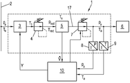
본 발명은 도 1에 도시된 것과 같은 알려진 가스 압력 제어 시스템과 유사한 구조물에 기초한다. 소비 측정 장치(1)는 매체 공급부(2)로부터 가스 매체를 끌어들인다. 매체 공급부(2)는 가령, 가스 보틀과 같은 가스 라인이나 매체 용기일 수 있다. 가스 매체는 대개 가변적인 흡입 압력(pe)에서 매체 공급부(2)로부터 끌려와서, 가스 경로(17)를 따라 소비 측정 장치(1)를 통과한다. 흡입 압력(pe)은 300 bar 이상까지의 값을 취할 수 있다. 끌려온 가스 매체는 가스 경로(17) 내의 조절 유닛(3)으로 공급되는데, 가스 매체는 결정된 온도(T1)로 가열된다. 그리고 나서, 가열된 가스 매체는 압력 제어 유닛(4)으로 공급되는데, 가스 매체는 팽창 압력(pred)으로 팽창된다. 압력 제어 유닛(4) 내의 팽창 때문에, 가스 매체의 온도도 팽창 온도(Tred)로 변한다. 가스 매체와 같은 천연 가스의 경우에, 줄-톰슨 효과 때문에, 가스 매체의 냉각이 발생한다. 수소의 경우에, 팽창은 심지어 가스 매체의 가열도 야기할 수 있다. 압력 제어 유닛(4)에서의 팽창 이후에, 매스(mass) 흐름 센서나 흐름 속도 센서와 같이, 가령 알려진 코리올리 센서와 같은 소비 센서(5)로 공급된다. 가스 매체는 배출 압력(pa)과 배출 온도(Ta)에서 소비 측정 장치(1)로부터 떠나고, 연소 엔진, 가스 터빈 또는 연료 셀과 같은 부하(6)로 공급된다. 그러므로, 부하(6)에 의한 가스 매체의 소비는 소비 센서(5)에 의해 측정된다. 정확한 측정치를 얻기 위하여, 높은 온도와 압력 안정성이 요구된다.The present invention is based on a structure similar to a known gas pressure control system such as that shown in Fig. The
도 1의 예시적인 실시예에서, 배출 압력(pa) 및 배출 온도(Ta)는, 압력 제어 유닛(4) 이후의 팽창 압력(pred)과 팽창 온도(Tred)와 본질적으로 일치한다. 대안적인 실시예에서, 팽창은 도 2와 관련하여 설명되는 바와 같이, 두 개의 단계(또는 복수의 단계)로 실행될 수도 있다. 본 명세서에서, 가스 매체는 소비가 측정되는 소비 센서(5) 이전에, 팽창 압력(pred)과 팽창 온도(Tred)로 전해진다. 소비 센서(5) 이후에 흐름의 방향으로, 제2 압력 제어 유닛(7)이 배치되는데, 이는 가스 매체를 배출 압력(pa)으로 팽창시켜서, 배출 온도(Ta)에 도달하게 한다. 바람직한 코리올리 센서와 같은 특정한 소비 센서(5)는 높은 압력에서, 그래서, 가스 매체의 더 높은 밀도에서 더 높은 정확성을 나타낸다. 그러므로, 충분히 높은 측정 정확성을 제공하는 압력까지 초기에 팽창하고, 이후에 요구되는 낮은 배출 압력(pa)으로만 팽창하는 것이 바람직하다.In the exemplary embodiment of Figure 1, the discharge pressure p a and the discharge temperature T a essentially correspond to the expansion pressure p red and the expansion temperature T red after the
부하(6)에 의해 가스 매체의 정확한 소비 측정을 얻기 위해, 배출 압력(pa) 및 배출 온도(Ta)는 가능한 일정하게 유지되어야 한다. 그러나, 배출 압력(pa)과 배출 온도(Ta)는 흡입 압력과 흡입 온도(Te), 공급된 가스 매체의 조성(줄-톰슨 효과 때문)은 물론 시간에 따라 강하에 가변하는 흐름 속도와 진폭에 강하게 의존한다. 이들 효과를 보상하기 위하여, 한 편으로, 배출 압력(pa)의 제어 및 특히 조절 유닛(3)의 매우 동적인 온도 제어가 요구된다.In order to obtain an accurate consumption measurement of the gaseous medium by the
배출 압력(pa)의 제어는, 가령 조절가능한 압력 제어 밸브와 같은 종래의 압력 제어 유닛(4, 7)에 의해 허용가능한 정확도로 수행될 수 있다. 그러므로, 배출 압력(pa)은 더 높은 레벨의 압력 제어 루프로 제어된다. 이를 위해, 소비 측정 장치(1)의 배출부에, 압력 센서(8)가 제공될 수 있으며, 이는 배출 압력(pa)을 검출하고 바람직하게는 디지털 형태로, 제어 유닛(10)으로 이를 공급한다. 제어 유닛(10)은, 원하는 또는 미리정한 배출 압력(pa)을 조절하기 위하여, 제1 압력 제어 유닛(4)(도 1) 또는 제1 및/또는 제2 압력 제어 유닛(4, 7)(도 2)을 제어한다. 도 2의 예시에서, 제1 압력 제어 유닛(4)이 가령, 일정한 팽창 압력(pred)으로 설정되고, 배출 압력(pa)은 오직 제2 압력 제어 유닛(7)에 의해서만 제어된다.The control of the discharge pressure p a can be carried out with an allowable accuracy by a conventional
온도를 제어하기 위하여, 배출 온도(Ta)는 온도 센서(9)에 의해 검출될 수 있고 제어 유닛(10)으로 바람직하게는 디지털 형태로 공급될 수 있다. 본 발명은 배출 온도(Ta)의 측정의 경우에 이하에 기술되는데, 다만 원칙적으로, 소비 측정 장치(1) 내의 임의의 위치에서의 온도가 사용될 수 있다는 것에 유의해야 한다. 특히, 배출 온도(Ta) 대신에, 조절 유닛(3) 이후의 온도(T1) 또는 소비 센서(5) 내의 온도(TS)는 물론 팽창 온도(Tred)도 사용될 수 있다. 제어 유닛(10)은, 가령 배출 온도(Ta), 조절 유닛(3) 이후의 온도(T1), 팽창 온도(Tred) 또는 소비 센서(5) 내의 온도(TS)와 같은 측정된 온도에 기초하여, 조절 유닛(3)을 위한 제어 변수(Y)를 계산하는데, 이에 의해 조절 유닛(3)이 제어된다. 이를 위해, 제어 유닛(10)에는 소비 센서(5)에 의해 측정된 실제 흐름 속도(![]()
![]()
![]()
![]()
![]()
![]()
도 3에 개략적으로 도시된 조절 유닛(3)에는 베이스 바디부(20)가 제공되는데, 이를 통해 매체 라인(22)이 안내되고, 이를 통해 조절될 가스 매체가 흐른다. 베이스 바디부(20)에, 온도 제어 유닛(23)이 배치되고, 결국 열을 저장하기 위한 버퍼 저장소(21)가 배치된다. 베이스 바디부(20)는 버퍼 저장소(21)와 직접적으로 접촉하지 않으나 온도 제어 유닛(23)에 의해 열적으로 분리된다. 버퍼 저장소(21)는 특정한 저장 매스를 가진 냉각 바디부로서 바람직하게 실행된다. 그러므로, 냉각 바디부는 일반적인 냉각 바디부와 같이 최대 열 발산을 위해 설계되지 않으나, 발산될 특정한 양의 열을 적어도 일정한 시간 동안 저장하게 된다. 온도 제어 유닛(23)은 베이스 바디부(20), 따라서 흐름 매체의 온도를 냉각하는데 사용된다. 이를 위해, 온도 제어 유닛(23)은 베이스 바디부(20)를 가열 및 냉각할 수 있다.The regulating
온도 제어 유닛(23)은 적어도 하나의 열전기 모듈(펠티에 소자), 바람직하게는 복수의 열전기 모듈로서 실행된다. 열전기 모듈은 유명한 반도체 소자인데, 이는 제1 가열 표면(24)과 제2 가열 표면(25) 사이에 배치된다. 반도체 소자에 공급되는 전기 전압의 극성에 따라, 제1 가열 표면(24)이 제2 가열 표면(25)보다 더 따뜻하거나 그 반대이다. 그러므로, 이러한 열전기 모듈은 공급 전압의 극성에 따라 베이스 바디부(20)를 가열하거나 냉각시킬 수 있다. 이러한 열전기 모듈의 구조와 기능은 충분히 알려져 있고, 이러한 열전기 모듈은 다양한 전력 클래스에서 시판되기 때문에, 자세한 설명은 생략한다.The
전기 공급 전압이 열전기 모듈에 인가되면, 열전기 모듈의 가열 표면들(24, 25) 중 하나는 알려진 바와 같이 냉각되고, 반대편 가열 표면은 따뜻해 진다. 두 가열 표면들(24, 25) 사이의 최대 온도 확산은 열전기 모듈의 동작 온도(더 따뜻한 가열 표면상의 온도)에 의존한다. 동작 온도가 높을수록, 냉각 가열 표면과 따뜻한 가열 표면 사이의 최대 가능한 온도 확산이 높아진다. 그러므로, 사용가능한 열전기 모듈로, 따뜻한 가열 표면상의 200℃까지의 온도가 달성될 수 있는 반면, 냉각 가열 표면은 100℃를 넘지 못한다. 공급된 전압의 극성의 간단한 변경에 의해, 냉각과 가열 사이의 빠른 스위칭이 달성될 수 있다. 조절 유닛(3)을 통과하는 가스 매체가 온도-제어되기 때문에, 가열은, 베이스 바디부(20)와 접촉하는 가열 표면(24)이 반대편 가열 표면(25)보다 더 따뜻하다는 것을 의미한다. 그러므로, 냉각은, 가열 표면(25)이 따뜻한 가열 표면이고, 베이스 바디부와 접촉하는 가열 표면(24)이 더 차가운 표면이라는 것을 의미한다.When an electrical supply voltage is applied to the thermoelectric module, one of the heating surfaces 24, 25 of the thermoelectric module is cooled as known, and the opposite heating surface is warmed. The maximum temperature spread between the two
그러나, 가스 매체의 온도를 제어하기 위하여, 가스 매체의 온도가 감소되거나 증가된다면, 공급 전압의 극성을 변화시키는 것이 반드시 필요한 것은 아니다. 이를 위해, 가열 표면들(24, 25) 사이의 온도 확산이 사용될 수도 있다. 그리고 나서, 더 작은 제어 간섭이 온도 확산을 통해 발생할 수 있는 반면, 바람직하게 열전기 모듈로 공급되는 전압의 극성을 반전시킴에 의해 더 강한 제어 간섭이 발생한다.However, to control the temperature of the gaseous medium, it is not necessary to change the polarity of the supply voltage if the temperature of the gaseous medium is reduced or increased. To this end, a temperature diffusion between the heating surfaces 24, 25 may be used. Then, while lesser control interference can occur through temperature diffusion, stronger control interference is generated by reversing the polarity of the voltage preferably supplied to the thermoelectric module.
온도 확산에 걸친 제어는, 가열 동작 동안에, 즉, 매체 라인(22) 내의 매체가 가열될 때, 버퍼 저장소(21)가 가열 저장소로서 사용된다는 사실에 의해 지지된다. 열전기 모듈로의 일정한 전압 공급의 경우에, 안정한 온도 확산은 열전기 모듈에서 설정된다. 더 적은 열 에너지나 열이 매체의 온도를 제어하는데 요구되고, 열전기 모듈상의 공급 전압이 감소되며, 온도 확산이 감소된다. 그러므로, 열전기 모듈의 베이스 바디부(20)와 접촉하는 가열 표면(24)상의 온도가 감소된다. 이와 동시에, 반대편 가열 표면(25)상의 온도가 증가된다. 그러므로, 온도 그래디언트가 가열 표면(25) 및 접촉하는 버퍼 저장소(21) 사이에서 형성되고, 버퍼 저장소(21) 내로의 열 흐름(열 흐름은 ![]()
![]()
![]()
![]()
조절 유닛(3)이 열전기 모듈을 가진 온도 제어 유닛(23)으로 기술되었더라도, 온도 제어 유닛(23)의 다른 실시예도 고려될 수 있다는 것은 명백하다. 온도 제어 유닛(23)은 가열 표면들(24, 25) 사이의 온도 확산을 가변시킬 수 있어야 한다. 물리적 관점에서 보면, 열전기 모듈의 동작은 열 펌프에 해당하고, 이는 더 낮은 온도에서의 영역으로부터 열 에너지를 끌어와서, 이를 더 높은 온도로 가열될 시스템으로 전송한다. 공급된 전압의 극성의 변경은 두 개의 열 펌프의 제공에 해당하고, 이는 상호 반대의 방법으로 동작한다. 그러므로, 원칙적으로, 열 펌프로서 형성될 수 있는 임의의 장비는 온도 제어 유닛(23)으로 고려될 수 있다.It is clear that another embodiment of the
본 발명에 따른, 빠르고 정확한 제어를 위한 전제 조건을 나타내는, 제어 관점으로부터 조절 유닛(3)의 이러한 이점을 사용하기 위하여, 버퍼 저장소(21)와 베이스 바디부(20) 사이의 기술된 열 흐름(![]()
![]()
제어 변수(Y)는 모델 파트(A)와 제어 파트(R)로 구성되는데, 즉, Y = A + R. 모델 파트(A)는 조절 유닛(3)을 모델링하고, 조절 유닛(3) 내의 매체의 온도를 제어하는데 요구되는 에너지나 전력(Pv)을 가능한 최적의 방법으로 계산하고, 이를 제어를 수행하기 위한 제어 변수로 변환한다. 팽창 이후에 획득하기 위한 가스 매체, 설정점 온도(Tsoll)의 조절을 위해 요구되는 전력(PG)은 알려진 수학식에 기초하여 계산될 수 있다.The control parameter Y is composed of a model part A and a control part R, i.e. Y = A + R. The model part A models the

줄-톰슨 효과 없이, 전력(PG)은 매체의 온도(가열 또는 냉각)를 제어하는데 요구되는 전력으로 감소된다. 실제 흐름 속도(![]()
![]()
선택적으로, 조절 유닛(3) 내의 전력 손실(PL)이 고려될 수도 있다. 매우 정확하고 빠른 제어를 위해, 전력 손실(PL)은 고려되어야 한다. 전력 손실(PL)은 가령, 조절 유닛(3)에서 주변 온도(Tamb)에서의 환경으로 열 발산되는 것으로 모델링될 수 있다. 주변 온도(Tamb)는 PT100 센서와 같은 적절한 온도 센서(13)에 의해 측정될 수도 있다. 그리고 나서, 전력 손실(PL)은 조절 유닛(3)의 구체적인 실시예로부터 획득되고 이하의 수학식에 따라 알려진 바와 같이 고려된 실험적 상수에 기초할 수 있다.Alternatively, the power loss (P L ) in the

조절 유닛(3) 내의 온도를 제어하기 위해 요구되는 전력(Pv)은 Pv = PG [+PL]로부터 획득되고, 이는 모델 파트(A)로서 사용될 수 있다. 용이하게 프로세스가능한 제어 변수로부터 얻기 위하여, 요구되는 전력(Pv)은 조절 유닛(3) 내에서 사용가능한 최대 전력(Pvmax)과 관련될 수도 있어서, 모델 파트는 
온도 제어 유닛(23)으로서 열전기 모듈을 가진 조절 유닛(3)의 구체적인 실시예에서, 요구되는 전력(Pv)은 공급 전압(Uv)으로도 변환될 수 있는데, 이는 열전기 모듈에 인가되어야 한다.In the
온도 제어 유닛(23)으로서 열전기 모듈을 가진 조절 유닛(3)의 구체적인 실시예에서, 요구되는 전력(Pv)은 공급 전압(Uv)으로 변환될 수 있는데, 이는 열전기 모듈에 인가되어야 한다. 조절 유닛(3) 내의 열전기 모듈의 옴 레지스턴스로, 공급 전압(Uv)은 알려진 관계식 ![]()

![]()
그러나, 열전기 모듈의 옴 레지스턴스(RCU)는 대개 알려지지 않고, 온도에 종속적이다. 옴 레지스턴스(RCU)를 결정하기 위해, 실험적 관계식이 실험에 기초하여 발견되었다.However, the ohmic resistance (R CU ) of the thermoelectric module is largely unknown and temperature dependent. To determine the ohmic resistance (R CU ), an experimental relationship was found based on the experiment.

열전기 모듈의 실제 온도(Tist)(용이하게 측정될 수 있음)가 알려진다면, 이로부터, 옴 레지스턴스(RCU)가 계산될 수 있다. 여기서 RCU20 및 RCU150은 실험적 상수이고, 이는 20℃ 및 150℃에서 열전기 모듈의 옴 레지스턴스(RCU)를 나타낸다.From this, the ohmic resistance (R CU ) can be calculated if the actual temperature of the thermoelectric module (T ist ) (which can be easily measured) is known. Where R CU20 and R CU150 are experimental constants, which represent the ohmic resistance (R CU ) of the thermoelectric module at 20 ° C and 150 ° C.
제어 변수(Y)의 제어 파트(R)는, 버퍼 저장소(21) 내의 사용가능한 양의 열를 사용함에 의해 배출 온도(Ta)(또는 언급된 바와 같은 또 다른 온도)의 매우 동적이고 정확한 제어를 가능하게 한다. 모델 파트(A)로, 설정점 온도(Tsoll)를 획득하기 위해, 온도 제어에 요구된 전력(Pv)은 이미 대략 조절되고, 제어 파트(R)는 원하는 정확한 제어 행동을 획득하기 위해, 제어 변수(Y)의 작은 교정만 수행한다.The control part R of the control variable Y has very dynamic and precise control of the discharge temperature T a (or another temperature as mentioned) by using a usable amount of heat in the
이미 언급된 바와 같이, 본 발명에 따른 조절 유닛(3)에서, 베이스 바디부(20)와 버퍼 저장소(21) 사이의 열 흐름(![]()
![]()
![]()
![]()
이와 관련하여, 설정점 온도(Tsoll)와 실제 온도(Tist) 모두가 그러므로, 가령, 배출 온도(Ta), 조절 유닛(3) 이후의 온도(T1), 팽창 온도(Tred) 또는 소비 센서(5) 내의 온도(TS)와 같이 제어될 온도를 말한다는 것에 유의해야 한다. 그러나, 모델 파트(A)와 제어 파트(R) 내의 설정점 온도(Tsoll)와 실제 온도(Tist)가 서로 다른 온도라고할 수 있는데, 가령, 모델 파트(A) 내의 소비 센서(5)의 TS 및 제어 파트(R) 내의 배출 온도(Ta)이다.In this regard, both the set point temperature T soll and the actual temperature T ist can therefore be determined, for example, by the discharge temperature T a , the temperature T 1 after the
제어 파트(R)에 대하여, 전통적인 제어 관련 접근법이 선택될 수 있는데, 이에 의해, 제어 파트(R)는 PI 제어기를 형성하기 위해, 비례 파트(YP)와 통합 파트(YI)으로 구성되어서, R = YP + YI이다. 이하에서는, 제어 파트(R)의 가능한 구체적인 실시예, 또는 비례 파트(YP)와 통합 파트(YI)가 기술된다.For the control part R a conventional control related approach can be selected whereby the control part R is composed of a proportional part Y P and an integral part Y I to form a PI controller , R = Y P + Y I. In the following, possible specific embodiments of the control part R, or proportional part Y P and integral part Y I , are described.
종래의 비례 제어기는 제어 오차(F)를 가중하는 증폭 인자(KP)로 구성되어서, KP·F이다. 종래의 통합 제어기는 시간의 함수로서 제어 오차(F)를 가중하는 증폭 인자(KI)로 구성되어서, KI·F·t이고, 여기서 증폭 인자(KI)는 리셋 시간(Tn)의 역수이다.The conventional proportional controller consists of an amplification factor (K P ) that weights the control error (F), and is K P · F. The conventional integrated controller is composed of an amplification factor K I that weighs the control error F as a function of time and is K I占 t t where the amplification factor K I is the reset time T n It is a reciprocal.
창의적인 제어기의 비례 파트(YP)에서, 그리고 통합 파트(YI)에서, 제어 오차(F)는 제어 오차(F)의 지수 함수 fP(eF) 또는 fI(eF)로서 도입된다. 그러므로, 가장 간단한 경우에, 비례 파트(YP)는 YP = KP·fP(eF)으로 획득되고, 통합 파트(YI)는 YI = KI·fI(eF)·t으로 획득된다. (가령, 10 ms의) 샘플링 시간(Δt)을 가진 시간-이산 제어기에 대하여, 통합 제어기는 YI(n) = YI(n-1) + ΔYI, 여기서, ΔYI = KI·fI(eF)·Δt으로 기술될 수도 있다. 제어 오차(R)의 지수 함수를 사용하여, 조절 유닛(3) 내의 열 전파가 근사화된다.In the proportional part (Y P ) of the creative controller and in the integral part (Y I ), the control error F is introduced as an exponential function f P (e F ) or f I (e F ) of the control error F . Thus, in the simplest case, the proportional part (Y P) is Y P = K P · f P (e F) is obtained, the integration part (Y I) is Y I = K I · f I (e F) · t. (E.g., the 10 ms) of time with a sampling time (Δt) - with respect to the discrete-controller, an integrated controller Y I (n) = Y I (n-1) + ΔY I, where, ΔY I = K I · f I (e F )? T. Using the exponential function of the control error R, the heat propagation in the
이미 기술된 바와 같이, 조절 유닛(3)으로 도입된 에너지는 한 편으로 가스 매체를 가열하는데 사용되고, 다른 면에는 전체 조절 유닛(3)을 가열하는데 사용된다. 주어진 에너지 공급으로, 가스 매체의 온도 증가는 가스 매체의 온도 감소보다 더 느리다. 언급한 바와 같이, 온도 증가는 버퍼 저장소(21) 내에 저장된 열에 의해 지지되어서, 이러한 효과는 이러한 사실에 의해 이미 약해진다.As already described, the energy introduced into the regulating
조절 유닛(3)의 이러한 비대칭 특성을 보상하기 위해, 비례 파트(YP)와 통합 파트(YI)는 적절한 교정 함수(YPowerCor)에 의해 교정될 수 있고, 이는 교정된 비례 파트(YPcor)와 교정된 통합 파트(YIcor)를 생성한다.To compensate for this asymmetric property of the

여기서, H(x)는 헤비사이드 함수이고, 이는, x < 0 에 대해 H(x) = 0 및 x ≥ 0 에 대해 H(x) = 1로, 실수를 세트 {0, 1}로 맵핑한다. 이는 교정 때문에, Tsoll > Tist 라면, 즉, 가스 매체 내의 온도가 증가되어야 할 때, 비례 파트(YP)와 통합 파트(YI)가 증폭된다는 것을 의미한다. Tist > Tsoll, 즉, 가스 매체의 온도가 감소되어야 할 때, 비례 파트와 통합 파트는 약해진다. 교정 함수(YPowerCor)로서, 가령, 
바람직한 실시예에서, 비례 파트(YP)는 수학식으로 획득된다.In a preferred embodiment, the proportional part (Y P ) is obtained in the form of:

통합 파트(YI)에서의 지수 함수(fI(eF))는 수학식과 같은 바람직한 실시예에서 획득된다.The exponential function f I (e F ) in the integrated part YI is obtained in a preferred embodiment such as the equation.

여기서, 간단하게 하기 위해, 통합 파트(YI)에서, 비례 제어기의 증폭 인자(KP)가 사용되는데, 이는 명백하게 필수적이지 않다는 것에 유의한다. 대신에, 통합 제어기의 증폭 인자(KI)가 명백하게 사용될 수 있다.Here, for the sake of simplicity, in the integrated part (Y I ), it is noted that the amplification factor (K P ) of the proportional controller is used, which is obviously not essential. Instead, the amplification factor (K I ) of the integrated controller can be used explicitly.
시간-이산 경우에, 통합 파트(YI)는 YI(n) = YI(n-1) + ΔYI, 여기서, ΔYI = KI·fI(eF)·Δt으로 다시 표현될 수 있다.Time - the discrete case, the integration part (Y I) is Y I (n) = Y I (n-1) + ΔY I, where, ΔY I = K I · f I (e F) · again be expressed as Δt .
여기서, H(x)는 다시 헤비사이드 함수인데, 부호는 부호 함수이고, 이는, x < 0 에 대해 sign(x) = -1, x = 0 에 대해 sign(x) = 0 및 x ≥ 0 에 대해 sign(x) = 1로, 실수를 세트 {-1, 0, 1}로 맵핑한다. 파라미터(σ)는 
제어기에 의해 결정되는 제어 변수(Y)는 Y = A + R = A + YP + YI을 따른다. 여기서, 비례 파트(YP)와 통합 파트(YI)의 사용이 선호되나 요구되지는 않다는 것에 유의한다. 비례 파트(YP) 또는 통합 파트(YI)만 사용될 수도 있다. 게다가, 제어 변수(Y)에서, 댐핑 인자(YDf)도 고려될 수 있다. 댐핑 인자(YDf)는 조절 유닛(3)의 과열을 막기 위해, 제1 댐핑 인자(YDf1)(가령, 실험치)를 포함할 수 있다. 게다가, 댐핑 인자(YDf)는 가령, 최대값 댐핑의 원리에 따라 설정점 값 오버슈팅을 댐핑할 수 있는 제2 댐핑 인자(YDf2)를 포함할 수 있다. 그리고 나서, 댐핑 인자(YDf)는 YDf = YDf1 + YDf2와 같다. 두 댐핑 인자들은 선택적이고, 서로 독립적으로 사용될 수 있다. 댐핑 인자(YDf)의 사용의 경우, 계산된 제어 변수(Y)는 ![]()
![]()
특수하게 설계된 조절 유닛(3)과 결합된 이러한 제어기를 사용하여, 원하는 온도가 매우 정확하게 설정될 수 있고, 높은 온도 안정성이 달성될 수 있는데, 이는 매체의 동적 흐름의 경우에, 소비 값(매스 흐름, 부피 흐름)의 정확한 결정을 위한 전제조건이다.With this controller combined with the specially designed
여기서, 상기 제어는 구체적인 응용예와 독립적이라는 것에 유의한다. 제어가 가스 매체의 소비 측정과 관련하여 기술되었더라도, 조절 유닛(3)은 상기 기술된 바와 같이, 일반항으로 제어될 수 있고, 그래서 다른 응용예에 대해서도 적절할 수 있는데, 특히 액체 매체는 온도 제어된다. 제어가 임의의 온도에 대해 가해질 수 있고, 즉, 가령, 조절 유닛(3) 이후의 온도(T1)에 가해질 수 있기 때문에, 가능하다.Note that the control is independent of the specific application. Although the control has been described in relation to the consumption measurement of the gaseous medium, the regulating
그러나, 이러한 제어기를 사용하여, 배출 압력(pa) 또는 흡입 압력(pe)의 함수 및 흐름 속도(![]()
![]()
![]()
![]()
![]()
![]()
![]()
![]()
여기서, 설정점 온도(Tsoll)는 소비 측정 장치(1) 내의 임의의 온도일 수 있으나, 소비 측정 장치(1)의 외부의 온도일 수도 있다는 것에 다시 한 번 유의한다. 그러나, 배출 온도(Ta)는 바람직한 설정점 온도(Tsoll)이다. 마찬가지로, 배출 압력(pa)은 소비 측정 장치(1) 내부 또는 외부, 가령 부하(6) 부근에서 측정될 수 있다.It is once again noted that the set point temperature T soll may be any temperature in the
기술된 제어는 온도 확산에 기초한 제어 및 교호하는 가열 및 냉각으로의 제어 모두에 적합하다. 온도 제어 유닛(23)으로 열전기 모듈의 경우, 공급 전압 극성은 제어 변수(Y)가 부호를 바꾸면, 스위칭된다. 제어 변수(Y)는 기술된 바와 같이, 범위 [-1, 1] 내에서 바람직하게 정규화된다.The described control is suitable for both control based on temperature diffusion and control for alternating heating and cooling. In the case of a thermoelectric module as the
가스 매체로서 수소의 경우, 압력 제어 유닛(4) 내에서의 팽창 때문에, 열이 발생한다. 이러한 경우, 흡입 온도(Te)는 조절 유닛(3)이 냉각되거나 가열되어야 하는지를 결정하다. 본질적으로 액체 매체에도 동일하게 유효하다.In the case of hydrogen as a gaseous medium, heat is generated due to expansion in the
냉각을 지원하기 위하여, 추가적인 냉각 장치(26)가 가령, 냉각 매체가 흐르는 냉각 라인(27)으로서 조절 유닛(3)의 버퍼 저장소(21) 내에 제공될 수 있다. 그리고 나서, 제어는 냉각 장치(26)의 제어로 확장될 수 있는데, 이를 통해 냉각 장치(26)에 의한 능동 냉각부가 고려된다. 그리고 나서, 가령, 흐름 속도(![]()
![]()
능동 냉각부의 제어는 바람직하게, 어떤 특징으로 제공된다. 냉각 장치(26)에 의한 능동 냉각부는 기본 부하를 커버하는 반면, 온데 제어 유닛(28)은 매우 동적인 교란을 보상해야 한다. 그러나, 온도 제어 유닛(28)이 영점 주위에서 동작해야 하는 것을 피하기 위해(이는 가열과 냉각 사이를 연속적으로 스위칭하는 것을 야기할 수 있음), 온도 제어 유닛(28)은 항상 냉각 부하의 파트를 견디는 것을 목적으로 한다. 온도 제어 유닛(28)으로서 펠티에 소자의 경우, 이는 극성의 연속적인 스위칭을 의미하는데, 이는 펠티에 소자에 영구적인 손상을 야기할 수 있다. 이를 차치하고서라도, 영 주위에서의 동작의 경우, 조절 유닛(3)을 제어하기 위한 버퍼 저장소의 이점도 놓칠 것이다. 마지막으로, 그러나 중요한 것은, 이러한 제어에 대한 부정적인 영향을 피하기 위해, 능동 냉각부의 제어는 조절 유닛(3)의 제어와 가능한 분리될 것이다.The control of the active cooling section is preferably provided with certain features. The active cooling by the cooling
이들 요구사항을 이행하기 위하여, 제어기가 제안되는데, 온도 차이(ΔTK)가 지수 형태로 도입된다. 제어가 발생하는 온도 차이(ΔTK)는, 온도 제어 유닛(28)(이는 측정될 수 있음), 바람직하게는 버퍼 저장소(21)의 면(가열 표면(25))의 온도(TTE)와 냉각 매체의 실제 온도(TK) 사이의 차이이다. 온도 제어 유닛(28)이 영 주위에서 동작하는 것을 방지하기 위해, 미리정한 데드 밴드(Ttotb)도 정의될 수 있는데, 이는 온도 제어 유닛(28)의 온도(TTE)를 교정한다. 그러므로, 온도 제어 유닛(28)의 교정된 온도(TKH)가 획득되고, TKH = TTE - TTotb와 같으며, 온도 차이는 ΔTK = TKH - TK이다. 그러므로, P-제어기는 설계될 수 있고, 이는 다음과 같이, 냉각 장치(26)에 대한 제어 변수(YCP)를 결정한다.In order to fulfill these requirements, a controller is proposed in which the temperature difference (T K ) is introduced in exponential form. The temperature difference (ΔT K) for controlling the generation, the temperature control unit 28 (which can be measured), preferably a surface of the buffer store (21) temperature (T TE) of the (heated surface (25)) and Is the difference between the actual temperature of the cooling medium (T K ). In order to prevent the temperature control unit 28 from operating in the vicinity of zero, a predetermined dead band T totb may also be defined, which corrects the temperature T TE of the temperature control unit 28. Therefore, the calibrated temperature T KH of the temperature control unit 28 is obtained, and is equal to T KH = T TE - T Totb, and the temperature difference is T K = T KH - T K. Thus, a P-controller can be designed, which determines the control variable (Y CP ) for the

여기서, H는 다시 헤비사이드 함수이고, Y는 조절 유닛(3)의 제어로부터온 제어 변수이다. KCP는 P-제어기의 증폭 인자이다.Where H is again the Heavy Side function and Y is the control variable from the control of the
조절 유닛(3)의 제어와 냉각 장치(26)의 제어를 분리시키는 것을 보장하기 위하여, 냉각 장치(26)를 제어하는 것에 대한 반응 시간은 조절 유닛(3)을 제어하는 것에 대한 반응 시간보다 더 길어야 한다. 정의된 지연 시간을 가진 냉각 장치(26)의 제어를 제공하기 위하여, 필터(G)가 사용될 수 있다. 필터(G)는 입력 신호로서 냉각 장치(26)에 대한 제어 변수(YCP)를 수신하고, 필터링된 제어 변수(YCPF)를 계산하고, 그리고 나서, 이는 냉각 장치(26)에 대한 실제 제어 변수로서 사용되어서, YCPF = G(YCP)이다.In order to ensure that the control of the
이를 위해, 다양하게 알려진 필터(G)가 사용될 수 있다. 이러한 맥락에서, 이미징 분야에서 알려진 가우스 필터는 성공적인데, 왜냐하면, 이러한 필터는 어떠한 오버슈팅 및 최대 증가 시간이 결여된 것이 유명하기 때문이다. 게다가, 스레숄드를 넘는 모든 주파수가 댐핑된다. 이러한 가우스 필터가 잘 알려져서, 가우스 필터에 대한 세부사항은 본 명세서에서 생략된다. 가우스 필터를 기초로한 계산은 복잡하고, 많은 연산 능력을 요구하며, 이는 제어 응용예의 경우에 단점이라는 점도 잘 알려져 있다. 그러나, 연산 시간을 최소로하기 위한 해결책이 이미 기술 분양에 알려져 있다. 소위 이산 가우스 핵(Gauss nuclei) 또는 샘플링된 가우스 핵이 이러한 경우에 사용된다.For this purpose, various known filters (G) can be used. In this context, Gaussian filters known in the imaging arts are successful, because such filters are known to lack any overshooting and maximum increase time. In addition, all frequencies above the threshold are damped. As such Gaussian filters are well known, details of the Gaussian filters are omitted herein. Computation based on Gaussian filters is complex and requires a lot of computing power, which is also a drawback in the case of control applications. However, a solution for minimizing the computation time is already known in the technical publications. So-called discrete Gaussian nuclei or sampled Gaussian nuclei are used in this case.
버퍼 저장소 내의 능동 냉각부가 있는 실시예는 특히 액체에 관심이 있으나, 가스 매체에도 있다. 가령 -40 내지 150℃의 큰 제어 범위가, 온도 제어 유닛(28)으로서 펠티에 소자를 사용하여 조절 유닛(3)에 이러한 방식으로 달성된다. 조절 유닛(3)은 전체 제어 범위에서 요구되는 성능을 제공할 수 있고, 여전히 매우 동적이고 극도로 정확한 방식으로 온도를 제어할 수 있다.Embodiments with active cooling in the buffer reservoir are of particular interest to liquids, but also to gaseous media. A large control range of, for example, -40 to 150 DEG C is achieved in this manner in the
소비 측정 장치(1)의 바람직한 실시예가 도 5에 의해 가스 매체에 대해 이제 기술된다. 흡입 압력(pe)에서의 가스 매체는 매체 공급부(2)로부터 끌려오고 흡읍 라인(14)과 흡입 연결부(15)를 통해 소비 측정 장치(1)로 공급된다. 흡입 측에서, 소비 측정 장치(1)의 내부 혹은 외부에서, 가스 필터(30)도 제공될 수 있다. 가스 매체의 온도는 조절 유닛(3) 내에서, 그리고 이후의 압력 제어 유닛(4) 내에서 제어되고, 가스 매체의 압력은 팽창 압력(pred)으로 팽창된다. 그리고 나서, 팽창된 가스 매체는 소비 센서(5)를 통과하고, 소비량(매스 흐름, 부피 흐름)이 측정된다. 제2 압력 제어 유닛(7)은 소비 센서(5) 이후에 위치되고, 원하는 배출 압력(pa)을 설정한다. 그리고 나서, 조절된 가스 매체는 배출(16)을 통해 끌려져서, 가령, 부하(6)로 공급된다.A preferred embodiment of the
이하에 기술된 모든 함수와 구성은 마스터 제어 유닛(40)에 의해 제어되는데, 제어 유닛(10)도 실행된다. 센서도 이들 측정값을 마스터 제어 유닛으로 제공한다. 간결성을 위해, 요구된 제어 라인 및 측정 라인은 도 4에서 생략되었다.All the functions and configurations described below are controlled by the
소비 센서(5)는 이러한 경우, 두 개 이상의 직렬 연결된 코리올리 센서(31, 32)로 구성된다. 두 코리올리 센서(31, 32)는 서로 다른 측정 범위를 가진다. 그러므로, 소비량에 의존하여, 측정치는 최적의 코리올리 센서(측정 정확성의 의미)에 스위칭될 수 있다. 이는 바이패스 밸브(33)를 통해 본 명세서에서 발생하는데, 이는 제2 코리올리 센서(32) 주위의 바이패스 라인(34)에 배치된다. 본 명세서에서 스위칭 밸브(33)는 압축 공기에 의해 작동된다. 이를 위해, 압축 공기 밸브 블록(35)이 제공되는데, 이는 압축 공기 연결부(36)를 통해 외부의 압축 공기 공급부에 연결된다. 그러므로, 제2 코리올리 센서(32)는 바이패스 스위칭 밸브(33)를 작동시킴에 의해 추가 또는 제거될 수 있다. 두 코리올리 센서(31, 32)가 활성화되면, 측정 결과의 타당성 확인이 가로지르는 측정 범위에서 획득될 수 있고, 이는 자가-진단에 사용될 수 있다.In this case, the
소비 측정 장치(1)에서, 과흐름 라인(37)도 제공되는데, 이는 과흐름 연결부(38)에 연결된다. 과흐름 라인(37)은 소비 측정 장치(1)에서 과압 밸브를 통해 가스 매체를 위한 가스 경로에 연결된다. 이러한 방식으로 소비 측정 장치(1)는 이상적인 과압으로부터 보호될 수 있다.In the
소비 센서(5)의 다운스트림 측에, 영-조절 밸브(39)가 배치된다. 그러므로, 소비 센서(5)의 영점은 확인될 수 있다. 이를 위해, 영-조절 밸브(39)는 폐쇄되고(여기서, 압축 공기에 의해 다시), 소비 센서(5)의 측정 밸브는 부피 흐름이 영으로 평가된다. 측정된 값이 스레숄드를 초과하면, 영점을 설정하기 위해 내부 센서 조절은 활성화될 수 있다. 소비 센서(5)의 영점 드리프트는 그러므로 보상될 수 있다.On the downstream side of the
소비 측정 장치(1)에서, 도시된 예시에서, 비활성 가스 퍼징(41)도 제공된다. 이를 위해, 비활성 가스 압력 저장소(42)가 제공되는데, 이는 비활성 스위치 밸브(43)를 통해, 소비 측정 장치(1)로 통하는 가스 매체의 가스 경로에 연결될 수 있다. 비활성 가스 압력 저장소(42)는 비활성 가스 연결부(44)를 통해 채워질 수 있다. 소비 측정 장치(1)를 퍼징하는데 사용되는 비활성 가스(가령, 질소)는 비활성 가스 연결부(44)를 통해 직접 공급될 수도 있다.In the
비활성 가스로 소비 측정 장치(1)를 퍼징하기 위하여, 흡입 측 확인 밸브(45)가 폐쇄되고, 배출측 스위치 밸브(46)가 과흐름 라인(37)을 스위칭 온한다. 이와 동시에, 비활성 가스 스위치 밸브(43)는 개방된다. 그러므로, 소비 측정 장치(1) 내에 남아 있는 가압된 가스 매체는 과흐름 라인(37)을 통해 달아날 수 있다. 압력이 충분히 감소되면, 비활성 가스 압력 저장소(42)가 비워질때 까지, 또는 일정한 시간 동안, 논-리턴 밸브(47)가 개방되고, 소비 측정 장치(1)는 비활성 가스에 의해 퍼징된다. 퍼징 이후에, 소비 측정 장치(1)는 비활성 가스, 바람직하게는 약간 과압된 가스로 채워지고, 안전한 상태에 있다. 흡입 가스 퍼징은 소비 측정 장치(1)의 안전성을 증가시키고, 가령, 장비의 비활성이나 긴급 정지의 경우에도 활성화될 수 있다.In order to purge the
Claims (28)


으로부터 계산되는, 조절 유닛을 제어하기 위한 방법.6. The method according to claim 5, wherein the proportional part (Y P )
≪ / RTI >

으로부터 계산되는, 조절 유닛을 제어하기 위한 방법.8. The method of claim 7, wherein the calibrated proportional part (Y Pcor )
≪ / RTI >

으로부터 계산되는, 조절 유닛을 제어하기 위한 방법.11. The method according to claim 9 or 10, wherein the exponential function f I (e F ) in the integrated part (Y I )
≪ / RTI >

으로부터 계산되는, 조절 유닛을 제어하기 위한 방법.13. The method of claim 12, wherein the calibrated integral part (YIcor)
≪ / RTI >

에 따라 계산되는, 조절 유닛을 제어하기 위한 방법.17. The method of claim 16, wherein the control variable (Y CP )
≪ / RTI >
Applications Claiming Priority (3)
| Application Number | Priority Date | Filing Date | Title |
|---|---|---|---|
| ATA50530/2015A AT517215B1 (en) | 2015-06-23 | 2015-06-23 | Method for controlling a conditioning unit and consumption meter with such a conditioning unit |
| ATA50530/2015 | 2015-06-23 | ||
| PCT/EP2016/063122 WO2016206983A2 (en) | 2015-06-23 | 2016-06-09 | Method for the feed-back control of a conditioning unit and consumption measuring device having such a conditioning unit |
Publications (1)
| Publication Number | Publication Date |
|---|---|
| KR20180020153A true KR20180020153A (en) | 2018-02-27 |
Family
ID=56132914
Family Applications (1)
| Application Number | Title | Priority Date | Filing Date |
|---|---|---|---|
| KR1020177036170A KR20180020153A (en) | 2015-06-23 | 2016-06-09 | METHOD FOR CONTROLLING CONTROL UNIT AND CONSUMPTION MEASURING DEVICE WITH THAT CONTROL UNIT |
Country Status (7)
| Country | Link |
|---|---|
| US (1) | US20180275697A1 (en) |
| EP (1) | EP3314348A2 (en) |
| JP (1) | JP2018520436A (en) |
| KR (1) | KR20180020153A (en) |
| CN (1) | CN108027622A (en) |
| AT (1) | AT517215B1 (en) |
| WO (1) | WO2016206983A2 (en) |
Families Citing this family (8)
| Publication number | Priority date | Publication date | Assignee | Title |
|---|---|---|---|---|
| JP6732391B2 (en) * | 2018-06-12 | 2020-07-29 | 日本電信電話株式会社 | Calculating device, calculating method and program |
| AT521899B1 (en) * | 2018-12-12 | 2020-11-15 | Avl List Gmbh | Measuring system and method for measuring a mass flow rate, a density, a temperature or a flow rate |
| AT522357B1 (en) * | 2019-03-18 | 2020-11-15 | Avl List Gmbh | Measuring system for measuring a mass flow rate, a density, a temperature and / or a flow rate |
| AT523401B1 (en) * | 2020-04-30 | 2021-08-15 | Avl List Gmbh | Measuring system for measuring a flow rate |
| EP4030149A1 (en) * | 2021-01-13 | 2022-07-20 | Linde GmbH | System and method for determining a mass flow |
| CN113447087B (en) * | 2021-06-25 | 2022-08-23 | 北京航空航天大学 | Flow measurement method based on dynamic optimization of three pressure sensors |
| CN113419584B (en) * | 2021-07-21 | 2022-05-20 | 中国人民解放军63798部队 | Rocket fairing internal environment rapid recovery method based on model predictive control |
| CN113717757B (en) * | 2021-11-03 | 2022-02-08 | 华能(天津)煤气化发电有限公司 | Variable proportion feedback adjustment method for pulverized coal pressurized conveying |
Family Cites Families (8)
| Publication number | Priority date | Publication date | Assignee | Title |
|---|---|---|---|---|
| AT4978U1 (en) * | 2000-11-22 | 2002-01-25 | Avl List Gmbh | METHOD FOR CONDITIONING THE INTAKE AIR AND THE EXHAUST GAS PRESSURE OF AN INTERNAL COMBUSTION ENGINE |
| AT7888U3 (en) * | 2005-05-27 | 2006-07-15 | Avl List Gmbh | METHOD AND DEVICE FOR CONTINUOUS MEASUREMENT OF DYNAMIC FLUID CONSUMPTION |
| JP4497191B2 (en) * | 2007-11-06 | 2010-07-07 | トヨタ自動車株式会社 | Control device for internal combustion engine |
| CN101470020B (en) * | 2007-12-25 | 2011-06-29 | 清华大学 | Detection system and method for mesomeric state hydrogen gas consumption |
| AT10955U3 (en) * | 2009-10-01 | 2010-09-15 | Avl List Gmbh | DEVICE FOR DETERMINING THE FUEL CONSUMPTION OF AN INTERNAL COMBUSTION ENGINE |
| US8682149B2 (en) * | 2009-11-19 | 2014-03-25 | Gaumer Company, Inc. | Flow measurement with electric heaters |
| DE112011101398B4 (en) * | 2010-04-20 | 2016-12-15 | Suzuki Motor Corporation | Fuel supply control device for internal combustion engine |
| DE102010042013A1 (en) * | 2010-10-06 | 2012-04-12 | Robert Bosch Gmbh | Method for adjusting a temperature of a sensor element |
-
2015
- 2015-06-23 AT ATA50530/2015A patent/AT517215B1/en not_active IP Right Cessation
-
2016
- 2016-06-09 KR KR1020177036170A patent/KR20180020153A/en unknown
- 2016-06-09 JP JP2017566851A patent/JP2018520436A/en active Pending
- 2016-06-09 CN CN201680037331.XA patent/CN108027622A/en active Pending
- 2016-06-09 US US15/739,506 patent/US20180275697A1/en not_active Abandoned
- 2016-06-09 EP EP16729533.6A patent/EP3314348A2/en not_active Withdrawn
- 2016-06-09 WO PCT/EP2016/063122 patent/WO2016206983A2/en active Application Filing
Also Published As
| Publication number | Publication date |
|---|---|
| AT517215B1 (en) | 2016-12-15 |
| WO2016206983A3 (en) | 2017-03-02 |
| CN108027622A (en) | 2018-05-11 |
| WO2016206983A2 (en) | 2016-12-29 |
| US20180275697A1 (en) | 2018-09-27 |
| JP2018520436A (en) | 2018-07-26 |
| EP3314348A2 (en) | 2018-05-02 |
| AT517215A4 (en) | 2016-12-15 |
Similar Documents
| Publication | Publication Date | Title |
|---|---|---|
| KR20180020153A (en) | METHOD FOR CONTROLLING CONTROL UNIT AND CONSUMPTION MEASURING DEVICE WITH THAT CONTROL UNIT | |
| US10443784B2 (en) | System for controlling gas supply unit | |
| JP5172615B2 (en) | Temperature control device | |
| KR102384035B1 (en) | Flow rate control apparatus, storage medium storing program for flow rate control apparatus and flow rate control method | |
| US20130056194A1 (en) | Motor vehicle cooling device | |
| US6554196B2 (en) | Temperature control device | |
| US6993418B2 (en) | Method and apparatus for latent temperature control for a device under test | |
| KR20070106653A (en) | Circulation cooling system for cryogenic cable | |
| JP2018520436A5 (en) | ||
| JP6509866B2 (en) | Improved flow control system for supplying propellant fluid to spacecraft electric thrusters | |
| KR20140135185A (en) | System and method for improving the accuracy of a rate of decay measurement for real time correction in a mass flow controller or mass flow meter by using a thermal model to minimize thermally induced error in the rod measurement | |
| KR20180100391A (en) | Method of controlling cooling system for transporting coolant to a heat exchanger in a vehicle | |
| CN105960513B (en) | Thermostat device for a motor vehicle cooling system, cooling system equipped with such a thermostat device and method for controlling a heating module | |
| Wolf et al. | Investigation of temperature control characteristics of loop heat pipes | |
| EP2890940B1 (en) | A method for controlling a chiller system | |
| KR20180062240A (en) | fuel supply apparatus | |
| US20190085752A1 (en) | Method and system for coolant flow control for a prime mover in a vehicle propulsion system | |
| US20190165387A1 (en) | Partial derivative based feedback controls for pid | |
| JPWO2006075406A1 (en) | Flow rate measuring method and flow rate measuring device | |
| KR20200142017A (en) | Conditioning device for controlling gas or liquid to a certain target temperature | |
| JP5871745B2 (en) | Fuel temperature control device | |
| KR20150093127A (en) | Method for functional testing of arrangement for dynamic fuel consumption measurement | |
| JP6129760B2 (en) | Temperature control device | |
| US20170027082A1 (en) | Aircraft heat exchange system including a thermoelectric device | |
| JP2013004205A (en) | Control method and control device for cooling water flowing in fuel cell |