KR20180018268A - Apparatus and method for scheduling uplink data in mobile communication system - Google Patents
Apparatus and method for scheduling uplink data in mobile communication system Download PDFInfo
- Publication number
- KR20180018268A KR20180018268A KR1020170037144A KR20170037144A KR20180018268A KR 20180018268 A KR20180018268 A KR 20180018268A KR 1020170037144 A KR1020170037144 A KR 1020170037144A KR 20170037144 A KR20170037144 A KR 20170037144A KR 20180018268 A KR20180018268 A KR 20180018268A
- Authority
- KR
- South Korea
- Prior art keywords
- resource
- buffer
- allocated
- base station
- data
- Prior art date
Links
Images


Classifications
-
- H—ELECTRICITY
- H04—ELECTRIC COMMUNICATION TECHNIQUE
- H04W—WIRELESS COMMUNICATION NETWORKS
- H04W72/00—Local resource management
- H04W72/20—Control channels or signalling for resource management
- H04W72/21—Control channels or signalling for resource management in the uplink direction of a wireless link, i.e. towards the network
-
- H04W72/1284—
-
- H—ELECTRICITY
- H04—ELECTRIC COMMUNICATION TECHNIQUE
- H04W—WIRELESS COMMUNICATION NETWORKS
- H04W72/00—Local resource management
- H04W72/12—Wireless traffic scheduling
- H04W72/1263—Mapping of traffic onto schedule, e.g. scheduled allocation or multiplexing of flows
- H04W72/1268—Mapping of traffic onto schedule, e.g. scheduled allocation or multiplexing of flows of uplink data flows
-
- H—ELECTRICITY
- H04—ELECTRIC COMMUNICATION TECHNIQUE
- H04W—WIRELESS COMMUNICATION NETWORKS
- H04W28/00—Network traffic management; Network resource management
- H04W28/02—Traffic management, e.g. flow control or congestion control
- H04W28/0278—Traffic management, e.g. flow control or congestion control using buffer status reports
-
- H—ELECTRICITY
- H04—ELECTRIC COMMUNICATION TECHNIQUE
- H04W—WIRELESS COMMUNICATION NETWORKS
- H04W72/00—Local resource management
- H04W72/04—Wireless resource allocation
- H04W72/044—Wireless resource allocation based on the type of the allocated resource
- H04W72/0446—Resources in time domain, e.g. slots or frames
-
- H04W72/14—
-
- H—ELECTRICITY
- H04—ELECTRIC COMMUNICATION TECHNIQUE
- H04W—WIRELESS COMMUNICATION NETWORKS
- H04W72/00—Local resource management
- H04W72/20—Control channels or signalling for resource management
- H04W72/23—Control channels or signalling for resource management in the downlink direction of a wireless link, i.e. towards a terminal
Abstract
Description
본 발명은 이동 통신 시스템에서 단말과 기지국 간 상향링크 데이터를 송수신하는 방법 및 장치에 관한 것이다.The present invention relates to a method and apparatus for transmitting and receiving uplink data between a terminal and a base station in a mobile communication system.
단말에게 기지국으로 전송이 필요한 데이터가 발생하였을 경우, 단말은 기지국으로부터 데이터 전송에 필요한 자원을 할당받아야 한다. 이때, 단말은 기지국에게 SR (scheduling request) 정보를 전송하여 데이터 전송을 위한 자원을 할당받을 수 있다. When data that needs to be transmitted to the BS occurs in the MS, the MS needs to be allocated resources necessary for data transmission from the BS. At this time, the MS can receive SR (scheduling request) information and allocate resources for data transmission to the BS.
단말이 SR 정보를 전송하는데 사용되는 자원은 기지국으로부터 사전에 설정될 수 있다. 예를 들어, LTE 시스템의 경우, 단말은 상향링크 제어 정보 채널(PUCCH) 영역 중 일부를 스케줄링 요청 전송을 위해 사용할 수 있다. 단말로부터 스케줄링 요청을 받은 기지국은 해당 단말에게 상향 링크 자원을 설정하여 통지할 수 있다. The resources used by the terminal to transmit SR information can be preset from the base station. For example, in the case of an LTE system, a UE can use a part of an uplink control information channel (PUCCH) region for scheduling request transmission. The base station receiving the scheduling request from the UE can set up the uplink resource to the UE and notify the UE of the uplink resource.
단말은 이후 BSR (Buffer Status Report)을 전송하여 자신이 보내야 할 데이터가 더 있음을 기지국으로 알릴 수 있다. 다만, 기지국은 단말에게 몇 byte의 상향링크 데이터가 발생하였는지 BSR을 수신하기 전까지 알 수 없는 문제점이 있다.The MS may then transmit a BSR (Buffer Status Report) to inform the BS that there is more data to send. However, the base station has a problem that it can not be known until several bytes of uplink data have been generated to the terminal before receiving the BSR.
본 발명이 이루고자 하는 기술적인 과제는, 이동 통신 시스템에서 단말과 기지국 간 상향링크 데이터 송수신 시 발생하는 지연을 감소시킬 수 있는 방법 및 장치를 제공한다.SUMMARY OF THE INVENTION The present invention provides a method and apparatus for reducing delay occurring in uplink data transmission / reception between a terminal and a base station in a mobile communication system.
본 발명의 실시예에 따른 이동 통신 시스템에서 단말의 상향링크 스케줄링 방법은, 버퍼에 저장된 데이터량을 확인하는 단계와. SR(scheduling request)을 생성하는 단계와, 기지국으로부터 상향링크 자원을 할당받도록 상기 기지국으로 상기 확인된 데이터량에 기반하여 상기 SR을 전송하는 단계를 포함한다.A method for uplink scheduling of a UE in a mobile communication system according to an exemplary embodiment of the present invention includes: checking an amount of data stored in a buffer; Generating a scheduling request (SR), and transmitting the SR based on the determined amount of data to the base station to receive uplink resources from the base station.
상기 SR을 전송하는 단계는, 상기 확인된 데이터량에 기반하여 상기 SR의 전송 시점을 설정하는 단계와, 상기 설정된 전송 시점에 따라 상기 SR을 상기 기지국으로 전송하는 단계를 포함한다.The step of transmitting the SR includes setting a transmission time point of the SR based on the confirmed data amount, and transmitting the SR to the BS according to the set transmission time point.
상기 SR을 전송하는 단계는, 상기 확인된 데이터량에 기반하여 상기 SR의 전송 횟수를 설정하는 단계와, 상기 설정된 전송 횟수에 따라 상기 SR을 상기 기지국으로 전송하는 단계를 포함한다.The step of transmitting the SR includes setting a number of times of transmission of the SR based on the amount of the confirmed data and transmitting the SR to the BS according to the set number of times of transmission.
상기 SR을 전송하는 단계는, 상기 SR의 연속 전송 횟수를 설정하고, 상기 연속 전송 횟수에 대한 비트맵(bitmap)을 생성하는 단계와, 상기 확인된 데이터량과 상기 비트맵을 매핑하는 단계와, 상기 매핑 결과에 따라 상기 SR을 상기 기지국으로 전송하는 단계를 포함한다. The step of transmitting the SR may include the steps of: setting a number of consecutive transmissions of the SR and generating a bitmap for the number of consecutive transmissions; mapping the verified amount of data to the bitmap; And transmitting the SR to the BS according to the mapping result.
실시예에 따라, 상기 SR은 복수의 비트들(multi-bits)로 구성되고, 상기 확인된 데이터량과 상기 복수의 비트들이 매핑될 수 있다.According to an embodiment, the SR may be composed of a plurality of bits, and the determined amount of data and the plurality of bits may be mapped.
실시예에 따라, 상기 단말의 상향링크 스케줄링 방법은, 상기 SR이 발생할 수 있는 임의의 서브프레임 내의 서브프레임 인덱스와 상기 버퍼의 상태를 나타내는 버퍼 상태 인덱스를 매핑하는 단계를 포함하고, 상기 버퍼 상태 인덱스는 상기 버퍼에 저장된 데이터량에 따라 설정될 수 있다.According to an embodiment, the UL scheduling method of the UE includes mapping a sub-frame index in an arbitrary subframe in which the SR can occur to a buffer state index indicating a state of the buffer, May be set according to the amount of data stored in the buffer.
실시예에 따라, 상기 SR은 임의의 서브프레임(subframe) 내에서 제1 TTI(transmission time interval) 내의 제1 자원 및 제2 TTI 내의 제2 자원 적어도 하나에 할당될 수 있다.According to an embodiment, the SR may be assigned to at least one of a first resource in a first transmission time interval (TTI) and a second resource in a second TTI within an arbitrary subframe.
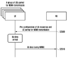
본 발명의 실시예에 따른 이동 통신 시스템에서 기지국의 상향링크 스케줄링 방법은, 단말로부터 SR(scheduling request)을 수신하는 단계와, 상기 SR을 이용하여 상기 단말의 버퍼에 저장된 데이터량을 확인하는 단계와, 상기 확인된 데이터량에 기반하여 상기 단말로 상향링크 자원을 할당하는 단계를 포함한다.A method for uplink scheduling of a base station in a mobile communication system according to an embodiment of the present invention includes receiving a scheduling request (SR) from a terminal, checking the amount of data stored in the buffer of the terminal using the SR, And allocating uplink resources to the UE based on the determined amount of data.
본 발명의 실시예에 따른 상향링크 데이터 스케줄링 방법 및 장치는, 단말과 기지국 간 상향링크 데이터 송수신 시 발생하는 지연을 감소시킬 수 있는 효과가 있다.The method and apparatus for uplink data scheduling according to the embodiment of the present invention can reduce the delay occurring in uplink data transmission / reception between the subscriber station and the base station.
도 1은 이동통신 시스템에서 상향링크 데이터를 송수신하는 제1 방법을 설명하는 순서도이다.
도 2는 이동통신 시스템에서 상향링크 데이터를 송수신하는 제2 방법을 설명하는 순서도이다.
도 3은 본 발명의 제1 실시예에 따른 상향링크 데이터 송수신 방법을 설명하는 도면이다.
도 4는 본 발명의 제1 실시예에 따라 버퍼 상태 인덱스와 상향링크 데이터의 매핑 관계의 예시를 나타낸다.
도 5는 본 발명의 제1 실시예에 따른 기지국과 단말 간 상향링크 자원 할당을 설명하는 순서도이다.
도 6은 본 발명의 제1 실시예에 따른 단말의 동작을 나타내는 순서도이다.
도 7은 본 발명의 제2-1 실시예에 따른 상향링크 데이터 송수신 방법을 설명하는 도면이다.
도 8은 본 발명의 제2-1 실시예에 따라 SR 전송 횟수와 상향링크 데이터 크기의 매핑 관계의 예시를 나타낸다.
도 9는 본 발명의 제2-1 실시예에 따라 SR 전송을 금지하는 타이머를 설정하는 과정을 나타낸다.
도 10은 본 발명의 제2-2 실시예에 따른 상향링크 데이터 송수신 방법을 설명하는 도면이다.
도 11은 본 발명의 제2-2 실시예에 따라 SR 전송과 관련된 비트맵와 상향링크 데이터의 매핑 관계의 예시를 나타낸다.
도 12는 본 발명의 제3 실시예에 따른 상향링크 데이터 송수신 방법을 설명하는 도면이다.
도 13a는 본 발명의 제3-1 실시예에 따라 다수의 비트로 구성된 SR과 상향링크 데이터의 매핑 관계의 예시를 나타낸다.
도 13b는 본 발명의 제3-2 실시예에 따라 코드 기반 SR과 상향링크 데이터의 매핑 관계의 예시를 나타낸다.
도 13c는 본 발명의 실시예에 따라 SR 전송 방법과 SR 전송 방법이 포함하는 정보의 대응 관계를 나타낸다.
도 14는 본 발명의 실시예에 따라 SR 자원에 버퍼 상태 인덱스를 설정하는 과정을 나타낸다.
도 15는 본 발명의 다른 실시예에 따라 SR 자원에 버퍼 상태 인덱스를 설정하는 과정을 나타낸다.
도 16은 본 발명의 또 다른 실시예에 따라 SR 자원에 버퍼 상태 인덱스를 설정하는 과정을 나타낸다.
도 17은 본 발명의 또 다른 실시예에 따라 SR 자원에 버퍼 상태 인덱스를 설정하는 과정을 나타낸다.
도 18은 본 발명의 또 다른 실시예에 따라 SR 자원에 버퍼 상태 인덱스를 설정하는 과정을 나타낸다.
도 19는 본 발명의 또 다른 실시예에 따라 SR 자원에 버퍼 상태 인덱스를 설정하는 과정을 나타낸다.
도 20은 본 발명의 또 다른 실시예에 따라 SR 자원에 버퍼 상태 인덱스를 설정하는 과정을 나타낸다.
도 21은 본 발명의 제4-1 실시예에 따른 상향링크 데이터 송수신 방법을 설명하는 도면이다.
도 22는 본 발명의 제4-2 실시예에 따른 상향링크 데이터 송수신 방법을 설명하는 도면이다.
도 23은 본 발명의 제5-1 실시예에 따른 상향링크 송수신 방법을 설명하는 도면이다.
도 24는 본 발명의 제5-2 실시예에 따른 상향링크 송수신 방법을 설명하는 도면이다.
도 25는 본 발명의 제5-3 실시예에 따른 상향링크 송수신 방법을 설명하는 도면이다.
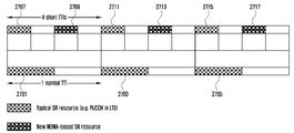
도 26은 본 발명의 실시예에 따라 SR 자원과 NOMA 기반 SR 자원이 공존하는 상황을 나타내는 도면이다.
도 27은 본 발명의 다른 실시예에 따라 SR 자원과 NOMA 기반 SR 자원이 공존하는 상황을 나타내는 도면이다.
도 28은 본 발명의 실시예에 따라 서비스 별로 SR 자원이 사용되는 것을 설명하는 도면이다.
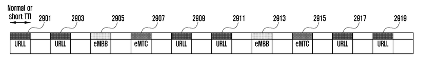
도 29는 본 발명의 다른 실시예에 따라 서비스 별로 SR 자원이 사용되는 것을 설명하는 도면이다.
도 30은 본 발명의 또 다른 실시예에 따라 서비스 별로 SR 자원이 사용되는 것을 설명하는 도면이다.
도 31은 본 발명의 실시예에 따른 SR 송수신 절차를 설명하는 도면이다.
도 32는 본 발명의 실시예에 따라 멀티-비트 SR 신호에 관련된 정보를 송수신하는 과정을 설명하는 도면이다.
도 33은 본 발명의 실시예에 따라 최소 초기 UL 자원 크기에 관한 정보를 송수신하는 과정을 설명하는 도면이다.
도 34는 본 발명의 실시예에 따른 기지국을 나타내는 도면이다.
도 35는 본 발명의 실시예에 따른 기지국을 나타내는 도면이다.1 is a flowchart illustrating a first method of transmitting and receiving uplink data in a mobile communication system.
2 is a flowchart illustrating a second method of transmitting and receiving uplink data in a mobile communication system.
3 is a view for explaining an uplink data transmission / reception method according to the first embodiment of the present invention.
FIG. 4 illustrates an example of a mapping relationship between a buffer state index and uplink data according to the first embodiment of the present invention.
5 is a flowchart illustrating uplink resource allocation between a BS and a UE according to the first embodiment of the present invention.
6 is a flowchart showing the operation of a terminal according to the first embodiment of the present invention.
7 is a view for explaining a method for transmitting and receiving uplink data according to a second embodiment of the present invention.
FIG. 8 illustrates an example of a mapping relationship between an SR transmission count and an uplink data size according to the second embodiment of the present invention.
FIG. 9 shows a process of setting a timer for prohibiting SR transmission according to the second embodiment of the present invention.
10 is a view for explaining a method for transmitting and receiving uplink data according to a second embodiment of the present invention.
11 illustrates an example of a mapping relationship between a bitmap and uplink data related to an SR transmission according to a second embodiment of the present invention.
12 is a view for explaining a method of transmitting and receiving uplink data according to a third embodiment of the present invention.
FIG. 13A shows an example of a mapping relationship between an SR composed of a plurality of bits and uplink data according to the embodiment 3-1 of the present invention.
FIG. 13B shows an example of a mapping relationship between a code-based SR and uplink data according to the embodiment 3-2 of the present invention.
13C shows a correspondence relationship between information included in the SR transmission method and the SR transmission method according to the embodiment of the present invention.
FIG. 14 illustrates a process of setting a buffer status index on an SR resource according to an embodiment of the present invention.
FIG. 15 illustrates a process of setting a buffer status index on an SR resource according to another embodiment of the present invention.
16 illustrates a process of setting a buffer status index on an SR resource according to another embodiment of the present invention.
17 illustrates a process of setting a buffer status index on an SR resource according to another embodiment of the present invention.
18 shows a process of setting a buffer status index on an SR resource according to another embodiment of the present invention.
FIG. 19 shows a process of setting a buffer status index on an SR resource according to another embodiment of the present invention.
FIG. 20 illustrates a process of setting a buffer state index on an SR resource according to another embodiment of the present invention.
FIG. 21 is a view for explaining a method for transmitting and receiving uplink data according to the 4-1 embodiment of the present invention.
22 is a view for explaining a method for transmitting and receiving uplink data according to a fourth embodiment of the present invention.
23 is a view for explaining an uplink transmission / reception method according to the fifth embodiment of the present invention.
24 is a view for explaining an uplink transmission / reception method according to a fifth embodiment of the present invention.
FIG. 25 is a view for explaining an uplink transmission / reception method according to the fifth to third embodiments of the present invention. FIG.
26 is a diagram illustrating a situation where SR resources and NOMA-based SR resources co-exist according to an embodiment of the present invention.
FIG. 27 is a diagram illustrating a situation where SR resources and NOMA-based SR resources co-exist according to another embodiment of the present invention.
28 is a view for explaining that SR resources are used for each service according to an embodiment of the present invention.
29 is a view for explaining that SR resources are used for each service according to another embodiment of the present invention.
30 is a view for explaining the use of SR resources on a service-by-service basis according to another embodiment of the present invention.
31 is a view for explaining an SR transmission / reception procedure according to an embodiment of the present invention.
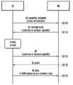
32 is a diagram illustrating a process of transmitting and receiving information related to a multi-bit SR signal according to an embodiment of the present invention.
33 is a view for explaining a process of transmitting and receiving information on a minimum initial UL resource size according to an embodiment of the present invention.
34 is a diagram illustrating a base station according to an embodiment of the present invention.
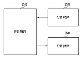
35 is a diagram illustrating a base station according to an embodiment of the present invention.
이하, 첨부된 도면을 참조하여 본 발명의 바람직한 실시 예들을 상세히 설명한다. 이 때, 첨부된 도면에서 동일한 구성 요소는 가능한 동일한 부호로 나타내고 있음에 유의해야 한다. 또한 본 발명의 요지를 흐리게 할 수 있는 공지 기능 및 구성에 대한 상세한 설명은 생략할 것이다. Hereinafter, preferred embodiments of the present invention will be described in detail with reference to the accompanying drawings. Note that, in the drawings, the same components are denoted by the same reference symbols as possible. Further, the detailed description of well-known functions and constructions that may obscure the gist of the present invention will be omitted.
본 명세서에서 실시 예를 설명함에 있어서 본 발명이 속하는 기술 분야에 익히 알려져 있고 본 발명과 직접적으로 관련이 없는 기술 내용에 대해서는 설명을 생략한다. 이는 불필요한 설명을 생략함으로써 본 발명의 요지를 흐리지 않고 더욱 명확히 전달하기 위함이다.In the following description of the exemplary embodiments of the present invention, descriptions of known techniques that are well known in the art and are not directly related to the present invention will be omitted. This is for the sake of clarity of the present invention without omitting the unnecessary explanation.
마찬가지 이유로 첨부 도면에 있어서 일부 구성요소는 과장되거나 생략되거나 개략적으로 도시되었다. 또한, 각 구성요소의 크기는 실제 크기를 전적으로 반영하는 것이 아니다. 각 도면에서 동일한 또는 대응하는 구성요소에는 동일한 참조 번호를 부여하였다.For the same reason, some of the components in the drawings are exaggerated, omitted, or schematically illustrated. Also, the size of each component does not entirely reflect the actual size. In the drawings, the same or corresponding components are denoted by the same reference numerals.
본 발명의 이점 및 특징, 그리고 그것들을 달성하는 방법은 첨부되는 도면과 함께 상세하게 후술되어 있는 실시 예들을 참조하면 명확해질 것이다. 그러나 본 발명은 이하에서 개시되는 실시 예들에 한정되는 것이 아니라 서로 다른 다양한 형태로 구현될 수 있으며, 단지 본 실시 예들은 본 발명의 개시가 완전하도록 하고, 본 발명이 속하는 기술분야에서 통상의 지식을 가진 자에게 발명의 범주를 완전하게 알려주기 위해 제공되는 것이며, 본 발명은 청구항의 범주에 의해 정의될 뿐이다. 명세서 전체에 걸쳐 동일 참조 부호는 동일 구성 요소를 지칭한다.BRIEF DESCRIPTION OF THE DRAWINGS The advantages and features of the present invention, and the manner of achieving them, will be apparent from and elucidated with reference to the embodiments described hereinafter in conjunction with the accompanying drawings. The present invention may, however, be embodied in many different forms and should not be construed as being limited to the embodiments set forth herein. Rather, these embodiments are provided so that this disclosure will be thorough and complete, and will fully convey the scope of the invention to those skilled in the art. Is provided to fully convey the scope of the invention to those skilled in the art, and the invention is only defined by the scope of the claims. Like reference numerals refer to like elements throughout the specification.
이 때, 처리 흐름도 도면들의 각 블록과 흐름도 도면들의 조합들은 컴퓨터 프로그램 인스트럭션들에 의해 수행될 수 있음을 이해할 수 있을 것이다. 이들 컴퓨터 프로그램 인스트럭션들은 범용 컴퓨터, 특수용 컴퓨터 또는 기타 프로그램 가능한 데이터 프로세싱 장비의 프로세서에 탑재될 수 있으므로, 컴퓨터 또는 기타 프로그램 가능한 데이터 프로세싱 장비의 프로세서를 통해 수행되는 그 인스트럭션들이 흐름도 블록(들)에서 설명된 기능들을 수행하는 수단을 생성하게 된다. 이들 컴퓨터 프로그램 인스트럭션들은 특정 방식으로 기능을 구현하기 위해 컴퓨터 또는 기타 프로그램 가능한 데이터 프로세싱 장비를 지향할 수 있는 컴퓨터 이용 가능 또는 컴퓨터 판독 가능 메모리에 저장되는 것도 가능하므로, 그 컴퓨터 이용가능 또는 컴퓨터 판독 가능 메모리에 저장된 인스트럭션들은 흐름도 블록(들)에서 설명된 기능을 수행하는 인스트럭션 수단을 내포하는 제조 품목을 생산하는 것도 가능하다. 컴퓨터 프로그램 인스트럭션들은 컴퓨터 또는 기타 프로그램 가능한 데이터 프로세싱 장비 상에 탑재되는 것도 가능하므로, 컴퓨터 또는 기타 프로그램 가능한 데이터 프로세싱 장비 상에서 일련의 동작 단계들이 수행되어 컴퓨터로 실행되는 프로세스를 생성해서 컴퓨터 또는 기타 프로그램 가능한 데이터 프로세싱 장비를 수행하는 인스트럭션들은 흐름도 블록(들)에서 설명된 기능들을 실행하기 위한 단계들을 제공하는 것도 가능하다.At this point, it will be appreciated that the combinations of blocks and flowchart illustrations in the process flow diagrams may be performed by computer program instructions. These computer program instructions may be loaded into a processor of a general purpose computer, special purpose computer, or other programmable data processing apparatus, so that those instructions, which are executed through a processor of a computer or other programmable data processing apparatus, Thereby creating means for performing functions. These computer program instructions may also be stored in a computer usable or computer readable memory capable of directing a computer or other programmable data processing apparatus to implement the functionality in a particular manner so that the computer usable or computer readable memory The instructions stored in the block diagram (s) are also capable of producing manufacturing items containing instruction means for performing the functions described in the flowchart block (s). Computer program instructions may also be stored on a computer or other programmable data processing equipment so that a series of operating steps may be performed on a computer or other programmable data processing equipment to create a computer- It is also possible for the instructions to perform the processing equipment to provide steps for executing the functions described in the flowchart block (s).
또한, 각 블록은 특정된 논리적 기능(들)을 실행하기 위한 하나 이상의 실행 가능한 인스트럭션들을 포함하는 모듈, 세그먼트 또는 코드의 일부를 나타낼 수 있다. 또, 몇 가지 대체 실행 예들에서는 블록들에서 언급된 기능들이 순서를 벗어나서 발생하는 것도 가능함을 주목해야 한다. 예컨대, 잇달아 도시되어 있는 두 개의 블록들은 사실 실질적으로 동시에 수행되는 것도 가능하고 또는 그 블록들이 때때로 해당하는 기능에 따라 역순으로 수행되는 것도 가능하다.In addition, each block may represent a portion of a module, segment, or code that includes one or more executable instructions for executing the specified logical function (s). It should also be noted that in some alternative implementations, the functions mentioned in the blocks may occur out of order. For example, two blocks shown in succession may actually be executed substantially concurrently, or the blocks may sometimes be performed in reverse order according to the corresponding function.
이 때, 본 실시 예에서 사용되는 '~부'라는 용어는 소프트웨어 또는 FPGA또는 ASIC과 같은 하드웨어 구성요소를 의미하며, '~부'는 어떤 역할들을 수행한다. 그렇지만 '~부'는 소프트웨어 또는 하드웨어에 한정되는 의미는 아니다. '~부'는 어드레싱할 수 있는 저장 매체에 있도록 구성될 수도 있고 하나 또는 그 이상의 프로세서들을 재생시키도록 구성될 수도 있다. 따라서, 일 예로서 '~부'는 소프트웨어 구성요소들, 객체지향 소프트웨어 구성요소들, 클래스 구성요소들 및 태스크 구성요소들과 같은 구성요소들과, 프로세스들, 함수들, 속성들, 프로시저들, 서브루틴들, 프로그램 코드의 세그먼트들, 드라이버들, 펌웨어, 마이크로코드, 회로, 데이터, 데이터베이스, 데이터 구조들, 테이블들, 어레이들, 및 변수들을 포함한다. 구성요소들과 '~부'들 안에서 제공되는 기능은 더 작은 수의 구성요소들 및 '~부'들로 결합되거나 추가적인 구성요소들과 '~부'들로 더 분리될 수 있다. 뿐만 아니라, 구성요소들 및 '~부'들은 디바이스 또는 보안 멀티미디어카드 내의 하나 또는 그 이상의 CPU들을 재생시키도록 구현될 수도 있다.Herein, the term " part " used in the present embodiment means a hardware component such as software or an FPGA or an ASIC, and 'part' performs certain roles. However, 'part' is not meant to be limited to software or hardware. &Quot; to " may be configured to reside on an addressable storage medium and may be configured to play one or more processors. Thus, by way of example, 'parts' may refer to components such as software components, object-oriented software components, class components and task components, and processes, functions, , Subroutines, segments of program code, drivers, firmware, microcode, circuitry, data, databases, data structures, tables, arrays, and variables. The functions provided in the components and components may be further combined with a smaller number of components and components or further components and components. In addition, the components and components may be implemented to play back one or more CPUs in a device or a secure multimedia card.
이하 본 발명의 실시 예를 첨부한 도면과 함께 상세히 설명한다. 또한 본 발명을 설명함에 있어서 관련된 기능 혹은 구성에 대한 구체적인 설명이 본 발명의 요지를 불필요하게 흐릴 수 있다고 판단된 경우 그 상세한 설명은 생략한다. 그리고 후술되는 용어들은 본 발명에서의 기능을 고려하여 정의된 용어들로서 이는 사용자, 운용자의 의도 또는 관례 등에 따라 달라질 수 있다. 그러므로 그 정의는 본 명세서 전반에 걸친 내용을 토대로 내려져야 할 것이다. Hereinafter, embodiments of the present invention will be described in detail with reference to the accompanying drawings. In the following description of the present invention, detailed description of known functions and configurations incorporated herein will be omitted when it may make the subject matter of the present invention rather unclear. The following terms are defined in consideration of the functions of the present invention, and these may be changed according to the intention of the user, the operator, or the like. Therefore, the definition should be based on the contents throughout this specification.
이하, 기지국은 단말의 자원할당을 수행하는 주체로서, eNode B, Node B, BS (Base Station), 무선 접속 유닛, 기지국 제어기, 또는 네트워크 상의 노드 중 적어도 하나일 수 있다. 단말은 UE (User Equipment), MS (Mobile Station), 셀룰러폰, 스마트폰, 컴퓨터, 또는 통신기능을 수행할 수 있는 멀티미디어시스템을 포함할 수 있다. 본 발명에서 하향링크(Downlink; DL)는 기지국이 단말에게 전송하는 신호의 무선 전송경로이고, 상향링크는(Uplink; UL)는 단말이 기국에게 전송하는 신호의 무선 전송경로를 의미한다. 또한, 이하에서 LTE 혹은 LTE-A 시스템을 일례로서 본 발명의 실시예를 설명하지만, 유사한 기술적 배경 또는 채널형태를 갖는 여타의 통신시스템에도 본 발명의 실시예가 적용될 수 있다.Hereinafter, the base station may be at least one of an eNode B, a Node B, a base station (BS), a wireless access unit, a base station controller, or a node on a network. The terminal may include a user equipment (UE), a mobile station (MS), a cellular phone, a smart phone, a computer, or a multimedia system capable of performing communication functions. In the present invention, a downlink (DL) is a wireless transmission path of a signal transmitted from a base station to a mobile station, and an uplink (UL) is a wireless transmission path of a signal transmitted from a mobile station to a base station. In the following, embodiments of the present invention will be described as an example of an LTE or LTE-A system, but embodiments of the present invention may be applied to other communication systems having a similar technical background or channel form.
도 1은 이동통신 시스템에서 상향링크 데이터를 송수신하는 제1 방법을 설명하는 순서도이다.1 is a flowchart illustrating a first method of transmitting and receiving uplink data in a mobile communication system.
도 1에 도시된 방법은 LTE 또는 5G 이동통신 시스템에서 단말과 기지국 간 상향링크 데이터 송수신 절차를 나타낸다.The method shown in FIG. 1 shows an uplink data transmission / reception procedure between a UE and a base station in an LTE or 5G mobile communication system.
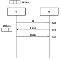
먼저, 단말에서 기지국으로 전송해야 할 상향링크 데이터가 발생하였다고 가정한다. 예를 들어, 상기 상향링크 데이터는 900 byte일 수 있다.First, it is assumed that uplink data to be transmitted from the mobile station to the base station is generated. For example, the uplink data may be 900 bytes.
S100 단계에서, 단말은 자신에게 할당된 SR (scheduling request) 기회에서 기지국으로 SR을 전송할 수 있다.In step S100, the MS can transmit the SR to the BS from the SR (scheduling request) opportunity assigned to the MS.
S110 단계에서, 상기 기지국은 상기 단말이 전송한 SR을 수신하고, 상기 SR에 응답하여 상기 단말로 상향링크 그랜트(uplink grant)를 전송함으로써 상기 단말로 상향링크 자원을 할당할 수 있다. In step S110, the BS may allocate uplink resources to the MS by receiving an SR transmitted by the MS and transmitting an uplink grant to the MS in response to the SR.
이때, 상기 기지국은 상기 단말에게 몇 byte의 상향링크 데이터가 발생하였는지 알지 못한다. 따라서, 상기 기지국은 상기 단말에게 임의의 크기에 해당하는 상향링크 자원을 할당할 수 있다. 예를 들어, 상기 기지국은 상기 단말에게 BSR (buffer status report)을 전송할 수 있을 만큼의 상향링크 자원을 할당할 수 있다.At this time, the BS does not know how many bytes of uplink data are generated in the MS. Accordingly, the BS can allocate uplink resources corresponding to an arbitrary size to the MS. For example, the BS may allocate an uplink resource sufficient to transmit a BSR (buffer status report) to the MS.
도 1에서는 상기 기지국이 300 byte의 상향링크 데이터를 전송할 수 있는 상향링크 자원을 상기 단말에게 할당하였다고 가정한다.In FIG. 1, it is assumed that the BS allocates uplink resources for transmitting uplink data of 300 bytes to the MS.
S120 단계에서, 상기 단말은 상기 기지국으로부터 상향링크 그랜트(uplink grant)을 수신하여 할당된 상향링크 자원을 통해 상향링크 데이터를 상기 기지국으로 전송할 수 있다.In step S120, the MS receives an uplink grant from the BS and transmits uplink data to the BS through the allocated uplink resource.
도 1에서는 단말에게 900 byte의 상향링크 데이터가 발생하였지만 기지국은 상기 단말에게 300 byte의 상향링크 데이터를 전송할 수 있는 자원을 할당하였으므로 상기 단말은 발생한 상향링크 데이터 전부(즉, 900 byte)를 전송하지 못한다.1, uplink data of 900 bytes is generated in the terminal, but the base station has allocated resources for transmitting the uplink data of 300 bytes to the terminal, the terminal transmits all the uplink data (i.e., 900 bytes) can not do it.
S120 단계에서, 단말은 기지국에게 BSR (Buffer Status Report)을 전송하여 자신이 보내야 할 상향링크 데이터가 600 byte 존재한다는 사실을 상기 기지국으로 알릴 수 있다.In step S120, the MS transmits a BSR (Buffer Status Report) to the BS to inform the BS of the existence of 600 bytes of uplink data to be transmitted.
S130 단계에서, 기지국은 단말로부터 BSR을 수신하고 BSR에 포함된 정보, 즉 단말이 보내야 할 상향링크 데이터가 600 byte 존재한다는 사실에 기반하여 추가적으로 단말에게 자원을 할당할 수 있다.In step S130, the BS receives the BSR from the MS and allocates resources to the MS in addition to the information included in the BSR, that is, the fact that the MS has 600 bytes of uplink data to be transmitted.
S140 단계에서, 단말은 기지국으로부터 상향링크 그랜트를 수신한 후 할당된 자원을 통해서 잔여 상향링크 데이터(즉, 600 byte)를 상기 기지국으로 전송할 수 있다.In step S140, the MS receives the uplink grant from the BS and then transmits the remaining uplink data (i.e., 600 bytes) to the BS through the allocated resources.
도 2는 이동통신 시스템에서 상향링크 데이터를 송수신하는 제2 방법을 설명하는 순서도이다.2 is a flowchart illustrating a second method of transmitting and receiving uplink data in a mobile communication system.
도 2에 도시된 방법은 LTE 또는 5G 이동통신 시스템에서 단말과 기지국 간 상향링크 데이터 송수신 절차를 나타낸다.The method shown in FIG. 2 shows an uplink data transmission / reception procedure between a terminal and a base station in an LTE or 5G mobile communication system.
먼저, 단말에서 기지국으로 전송해야 할 상향링크 데이터가 발생하였다고 가정한다. 예를 들어, 상기 상향링크 데이터는 900 byte일 수 있다.First, it is assumed that uplink data to be transmitted from the mobile station to the base station is generated. For example, the uplink data may be 900 bytes.
S200 단계에서, 단말은 자신에게 할당된 SR (scheduling request) 기회에서 기지국으로 SR을 전송할 수 있다.In step S200, the UE can transmit the SR to the BS from the SR (scheduling request) opportunity allocated thereto.
S210 단계에서, 상기 기지국은 상기 단말이 전송한 SR을 수신하고, 상기 SR에 응답하여 상기 단말로 상향링크 그랜트(uplink grant)를 전송함으로써 상기 단말로 상향링크 자원을 할당할 수 있다. In step S210, the BS may allocate uplink resources to the MS by receiving an SR transmitted by the MS and transmitting an uplink grant to the MS in response to the SR.
이때, 상기 기지국은 상기 단말에게 몇 byte의 상향링크 데이터가 발생하였는지 알 수 있다. 따라서, 상기 기지국은 상기 상향링크 데이터에 상응하는 정확한 크기의 상향링크 자원을 상기 단말에게 할당할 수 있다. 예를 들어, 상기 기지국은 상기 단말에게 900 byte의 상향링크 자원을 할당할 수 있다.At this time, the BS can know how many bytes of uplink data are generated in the MS. Therefore, the BS can allocate uplink resources of the correct size corresponding to the uplink data to the MS. For example, the BS may allocate uplink resources of 900 bytes to the MS.
S220 단계에서, 상기 단말은 상기 기지국으로부터 상향링크 그랜트(uplink grant)을 수신하여 할당된 상향링크 자원을 통해 상향링크 데이터를 상기 기지국으로 전송할 수 있다.In step S220, the MS receives an uplink grant from the BS and transmits uplink data to the BS through the allocated uplink resource.
도 2에서는 단말에게 900 byte의 상향링크 데이터가 발생함을 인지한 기지국이 상기 단말에게 900 byte의 상향링크 데이터를 전송할 수 있는 자원을 할당한다. 따라서, 도 1에 도시된 방법과 비교하여 도 2에 도시된 방법은 상향링크 데이터 송수신 절차에 소요되는 시간이 감소하는 효과가 있다.In FIG. 2, a base station recognizing that 900 bytes of uplink data is generated in the terminal allocates resources capable of transmitting 900 bytes of uplink data to the terminal. Therefore, compared with the method shown in FIG. 1, the method shown in FIG. 2 has an effect of reducing the time required for the uplink data transmission / reception procedure.
(서브프레임)delay
(Sub-frame)
상기 표 1을 참조하면, 제1 방법은 도 1에 도시된 방법에 따른 지연 시간을 나타내고, 제2 방법은 도 2에 도시된 방법에 따른 지연 시간을 나타낸다.Referring to Table 1, the first method represents the delay time according to the method shown in FIG. 1, and the second method shows the delay time according to the method shown in FIG.
여기서, 단말이 자신에게 할당된 SR 기회를 기다리는 시간은 제외하였고 ㅍ프로세싱(processing) 시간은 3 subframe (TTI와 동일)으로 가정하였다. Here, the processing time is assumed to be 3 subframes (equal to the TTI), except for the time for which the terminal waits for the SR opportunity allocated to the terminal.
도 1에 도시된 제1 방법은 기지국이 단말이 전송하려는 상향링크 데이터의 크기를 알지 못하므로 2 회에 걸쳐 상향링크 그랜트를 수행함으로써, 총 17 subframe의 소요 시간이 발생됨을 알 수 있다.In the first method shown in FIG. 1, since the base station does not know the size of the uplink data to be transmitted by the mobile station, the uplink grant is performed twice to find that a total time of 17 subframes is generated.
즉, 제1 방법의 동작에 따르면 기지국은 단말에게 몇 byte의 UL 데이터가 발생하였는지 BSR을 수신하기 전까지 알 수 없다. 따라서 첫 번째 UL grant을 통해서 할당된 자원에서 UL 송수신을 완료할 수 없게 된다. 또한 BSR을 송수신하는 동작 및 두 번째 UL grant 및 데이터 송수신 동작에서 지연이 발생함을 알 수 있다.That is, according to the operation of the first method, the BS can not know how many bytes of UL data are generated to the UE until it receives the BSR. Therefore, UL transmission and reception can not be completed in the resources allocated through the first UL grant. Also, it can be seen that a delay occurs in the operation of transmitting / receiving the BSR and the second UL grant and data transmission / reception operations.
도 2에 도시된 제2 방법은 기지국이 단말이 전송하려는 상향링크 데이터의 크기를 알고 있으므로 한 번의 상향링크 그랜트를 수행함으로써, 총 9 subframe의 소요 시간이 발생됨을 알 수 있다.In the second method shown in FIG. 2, since the base station knows the size of the uplink data to be transmitted by the mobile station, it performs one uplink grant, so that a total time of 9 subframes is generated.
즉, 기지국이 단말에게 발생한 UL 데이터의 크기를 알 수 있다면 단말로부터 SR을 수신한 후 첫 번째 UL grant에 단말이 모든 UL 데이터를 한 번에 전송할 수 있도록 충분한 양의 자원을 할당해 줄 수 있다. 따라서, 단말과 기지국 사이에 BSR 절차가 수행되기 전에 UL 송수신이 완료되는 것이다.That is, if the BS knows the size of the UL data generated by the UE, the UE can allocate a sufficient amount of resources to the UE in order to transmit all the UL data to the first UL grant after receiving the SR from the UE. Therefore, the UL transmission / reception is completed before the BSR procedure is performed between the UE and the BS.
본 발명에서는 상향링크 송수신의 지연을 줄이기 위한 방법을 제안한다. 특히, 5G 이동통신 시스템에서는 저지연 서비스를 지원하는 것이 중요한 성능 지표 중의 하나이다. 이를 위해서 피지컬 레이어(physical layer)에서는 short TTI 및 NOMA (Non-Orthogonal Multiple Access) 기술을 연구하고 있다. 이들은 전송 관점에서 지연을 줄이기 위한 핵심적인 기술이지만 단말에게 발생한 UL 데이터의 크기까지는 고려하고 있지 않다.The present invention proposes a method for reducing the delay of uplink transmission / reception. Particularly, in the 5G mobile communication system, supporting low-delay service is one of important performance indicators. To this end, short TTI and non-orthogonal multiple access (NOMA) technologies are being studied in the physical layer. These are key technologies for reducing delay from the viewpoint of transmission, but do not consider the size of UL data generated in the UE.
또한 서비스 측면에서는 단말이 첫 번째 전송을 빨리 수행하는 것보다 현재 단말이 보내야 하는 저지연 서비스 관련 UL 데이터 전부를 한번에 신속히 전송하는 것이 더 중요하다. 이러한 관점에서 본 발명에서는 기지국이 단말로부터 BSR을 수신하지 않고도 단말에게 발생한 UL 데이터의 크기를 대략적으로 파악할 수 있도록 한다. 이는 단말이 SR 전송 후 첫 번째 UL 전송에서 자신에게 발생한 모든 UL 데이터를 기지국에게 전송할 수 있는 가능성을 제공함으로써 전체적인 UL 송수신 지연을 줄이는 효과가 있다.Also, in terms of service, it is more important to transmit all the UL data related to the low delay service that the present terminal should send at once, rather than the terminal performing the first transmission fast. From this point of view, the present invention enables the BS to roughly grasp the size of the UL data generated in the UE without receiving the BSR from the UE. This has the effect of reducing the overall UL transmission / reception delay by providing the possibility that the UE transmits all the UL data generated in itself in the first UL transmission after the SR transmission to the base station.
기지국이 단말로부터 BSR을 수신하지 않고도 단말에게 발생한 UL 데이터의 크기를 파악할 수 있는 방법으로써 본 발명에서는 SR 송수신 동작을 개선하는 방법을 제안한다. The present invention proposes a method of improving the SR transmission / reception operation by allowing the BS to grasp the size of the UL data generated in the UE without receiving the BSR from the UE.
본 발명에서 제안하는 방법은 다음과 같다.The method proposed in the present invention is as follows.
본 발명의 제1 실시예는 기지국이 단말로부터 BSR을 수신하지 않고도 SR 전송 시점에 기반하여 단말에게 발생한 UL 데이터의 크기를 파악할 수 있는 방법에 관한 것이다.A first embodiment of the present invention relates to a method for determining a size of UL data generated in a mobile station based on an SR transmission time without receiving a BSR from a mobile station.
본 발명의 제2-1 실시예는 기지국이 단말로부터 BSR을 수신하지 않고도 SR 전송 횟수에 기반하여 단말에게 발생한 UL 데이터의 크기를 파악할 수 있는 방법에 관한 것이다.The embodiment 2-1 of the present invention relates to a method of determining the size of UL data generated in the UE based on the number of SR transmissions without receiving a BSR from the UE.
본 발명의 제2-2 실시예는 기지국이 단말로부터 BSR을 수신하지 않고도 SR 전송 횟수의 해석 방법에 기반하여 단말에게 발생한 UL 데이터의 크기를 파악할 수 있는 방법에 관한 것이다.The embodiment 2-2 of the present invention relates to a method of determining the size of UL data generated in the UE based on an analysis method of the number of SR transmissions without receiving a BSR from the UE.
본 발명의 제3 실시예는 기지국이 단말로부터 BSR을 수신하지 않고도 Multi-bit SR에 기반하여 단말에게 발생한 UL 데이터의 크기를 파악할 수 있는 방법에 관한 것이다.A third embodiment of the present invention relates to a method for determining a size of UL data generated in a UE based on a Multi-bit SR without receiving a BSR from the UE.
본 발명에서는 다음을 가정한다. 이는 설명의 편의를 위한 것으로 다른 가정이 적용된 경우에도 동일한 원리로 적용될 수 있다.The present invention assumes the following. This is for convenience of explanation and can be applied to the same principle even when other assumptions are applied.
1. 각 단말은 매 subframe 마다 SR 기회를 갖는다. 이는 저지연 서비스를 사용하는 단말에게 합리적인 가정으로 볼 수 있다. 1. Each terminal has an SR opportunity per subframe. This can be viewed as a reasonable assumption for terminals using low-latency services.
2. 각 단말은 UL 데이터가 발생한 시점에 UL synchronized 상태여서 SR 전송 전에 별도의 RACH 절차를 수행할 필요가 없다.2. Each UE is in the UL synchronized state at the time when the UL data is generated and it is not necessary to perform a separate RACH procedure before the SR transmission.
[제1 실시예][First Embodiment]
도 3 내지 도 6은 본 발명의 제1 실시예를 설명하기 위한 도면들이다. 상기 제1 실시예는 단말의 SR 전송 시점과 버퍼 상태(buffer status) 사이의 관계를 설정하고 단말은 자신의 버퍼 상태에 따라서 SR 전송 시점을 조절하는 방법에 관한 것이다.3 to 6 are views for explaining the first embodiment of the present invention. The first embodiment relates to a method of setting a relation between an SR transmission time and a buffer status of a mobile station and adjusting the SR transmission time according to a buffer status of the mobile station.
여기서 버퍼 상태(buffer status)라는 용어는 단말에게 발생한 UL 데이터의 크기 또는 단말이 보내야 하는 UL 데이터의 크기를 의미한다. 이는 LTE 표준에서 사용되는 용어이다.Here, the term 'buffer status' refers to the size of UL data generated by the UE or the size of UL data to be transmitted by the UE. This is the term used in the LTE standard.
단말 및 기지국은 현재 서브프레임 인덱스(subframe index)에 대응하는 예비적 버퍼 상태 인덱스(preliminary buffer status index, 이하 P-BSI라 한다)을 정의한다. 여기서 P-BSI는 아래의 수학식 1처럼 모듈로(modulo) 연산을 통해서 M 단계로 표현될 수 있다.A terminal and a base station define a preliminary buffer status index (P-BSI) corresponding to a current subframe index. Here, P-BSI can be represented by M steps through a modulo operation as shown in
[수학식 1][Equation 1]
P-BSI [k-th subframe] = (10*SFN + subframe index) modulo (M)P-BSI [k-th subframe] = (10 * SFN + subframe index) modulo (M)
예를 들어, P-BSI는 도 3 및 도 4와 같이 4단계 (M = 4)로 표현될 수 있다.For example, P-BSI can be expressed in four steps (M = 4) as shown in FIG. 3 and FIG.
단말 및 기지국은 RRC signaling 등을 통해서 각 단계 (m)의 P-BSI에 해당하는 buffer status를 설정한다.The terminal and the base station set the buffer status corresponding to the P-BSI of each step (m) through RRC signaling.
도 3은 본 발명의 제1 실시예에 따른 상향링크 데이터 송수신 방법을 설명하는 도면이다.3 is a view for explaining an uplink data transmission / reception method according to the first embodiment of the present invention.
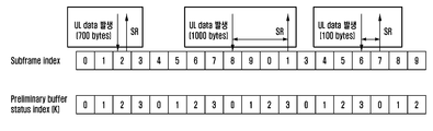
도 3을 참조하면, 10 개의 서브프레임이 구성되어 10 개의 서브프레임 인덱스(0 ~ 9)가 설정되고, 미리 정의된 4 개의 P-BSI가 설정될 수 있다. 이때, P-BSI와 상향링크 데이터의 관계는 미리 설정되어 있다.Referring to FIG. 3, ten subframes are configured, ten subframe indices (0 to 9) are set, and four predefined P-BSIs can be set. At this time, the relationship between P-BSI and uplink data is set in advance.
도 4는 본 발명의 제1 실시예에 따라 버퍼 상태 인덱스와 상향링크 데이터의 매핑 관계의 예시를 나타낸다.FIG. 4 illustrates an example of a mapping relationship between a buffer state index and uplink data according to the first embodiment of the present invention.
도 4를 참조하면, m = 0이면 단말의 buffer에 0에서 300 byte의 UL 데이터가 존재하고, m = 1이면 단말의 buffer에 300에서 600 byte의 UL 데이터가 존재하고, m = 2이면 단말의 buffer에 600에서 900 byte의 UL 데이터가 존재하고, m = 3이면 단말의 buffer에 900에서 1200 byte의 UL 데이터가 존재함을 의미한다.Referring to FIG. 4, when m = 0, UL data of 0 to 300 bytes exist in the buffer of the UE. If m = 1, UL data of 300 to 600 bytes exist in the buffer of the UE. the UL data of 600 to 900 bytes exists in the buffer and if m = 3, the UL buffer of 900 to 1200 bytes exists in the buffer of the UE.
도 3 및 도 4를 참조하면, 제3 서브프레임(m=2)에서 상향링크 데이터(예를 들어, 700 bytes)가 발생하면, 제3 서브프레임(m=2)은 제3 P-BSI(k=2)에 매핑되므로, 단말은 제3 서브프레임(m=2)에서 바로 SR을 전송할 수 있다.3 and 4, when uplink data (for example, 700 bytes) is generated in the third sub-frame m = 2, the third sub-frame m = k = 2), the UE can transmit the SR directly in the third sub-frame (m = 2).
또한, 제9 서브프레임(m=8)에서 상향링크 데이터(예를 들어, 1000 bytes)가 발생하면, 제9 서브프레임(m=8)은 제1 P-BSI(k=0)에 매핑되므로, 단말은 제9 서브프레임(m=8)에서 SR을 전송하지 않는다. 상기 단말은 상향링크 데이터(예를 들어, 1000 bytes)에 상응하는 제4 P-BSI(k=3)를 인지하고, 제4 P-BSI(k=3)에 상응하는 제2 서브프레임(m=1)에서 SR을 전송할 수 있다.When uplink data (for example, 1000 bytes) is generated in the ninth sub-frame (m = 8), the ninth sub-frame m = 8 is mapped to the first P-BSI (k = 0) , The terminal does not transmit the SR in the ninth sub-frame (m = 8). The terminal recognizes a fourth P-BSI (k = 3) corresponding to the uplink data (for example, 1000 bytes) and a second subframe m (k = 3) corresponding to the fourth P- = 1). ≪ / RTI >
또한, 제7 서브프레임(m=6)에서 상향링크 데이터(예를 들어, 100 bytes)가 발생하면, 제7 서브프레임(m=6)은 제4 P-BSI(k=3)에 매핑되므로, 단말은 제7 서브프레임(m=6)에서 SR을 전송하지 않는다. 상기 단말은 상향링크 데이터(예를 들어, 100 bytes)에 상응하는 제1 P-BSI(k=0)를 인지하고, 제1 P-BSI(k=0)에 상응하는 제8 서브프레임(m=7)에서 SR을 전송할 수 있다.Further, when uplink data (for example, 100 bytes) is generated in the seventh sub-frame (m = 6), the seventh sub-frame m = 6 is mapped to the fourth P-BSI , The terminal does not transmit the SR in the seventh sub-frame (m = 6). The terminal recognizes a first P-BSI (k = 0) corresponding to uplink data (for example, 100 bytes) and recognizes an eighth sub-frame m (k = 0) corresponding to a first P- = 7).
도 5는 본 발명의 제1 실시예에 따른 기지국과 단말 간 상향링크 자원 할당을 설명하는 순서도이다.5 is a flowchart illustrating uplink resource allocation between a BS and a UE according to the first embodiment of the present invention.
제1 실시예에 따라 단말 및 기지국이 각 단계의 P-BSI에 해당하는 buffer status을 설정할 수 있다.The UE and the BS can set the buffer status corresponding to the P-BSI of each step according to the first embodiment.
S500 단계에서, 단말은 자신이 저지연 서비스를 지원한다는 profile 정보를 기지국에게 알릴 수 있다. 또는 단말은 기지국에게 P-BSI을 설정해 줄 것을 요청할 수도 있다.In step S500, the UE can inform the BS of the profile information indicating that the UE supports the low-delay service. Alternatively, the terminal may request the base station to set the P-BSI.
S510 단계에서, 기지국은 단말에게 버퍼 상태 레벨(P-BSI를 몇 단계로 설정할 것인지에 대한 정보 (즉, M 값))을 알릴 수 있다. 여기서 RRC 메시지 내 MAC-MainConfig IE 등이 사용될 수 있다.In step S510, the base station can inform the terminal of the buffer status level (information on how many P-BSIs to set (i.e., M value)). Here, the MAC-MainConfig IE in the RRC message may be used.
S520 단계에서, 단말은 기지국에게 선호하는 버퍼 상태 레벨(즉, P-BSI를 몇 단계로 설정할 것인지에 대한 정보 (즉, M 값))을 알릴 수 있다. 여기서 새로 정의된 new IE 등이 사용될 수 있다.In step S520, the terminal may notify the base station of a preferred buffer state level (i.e., information on how many P-BSIs to set (i.e., M value)). Here, a newly defined new IE can be used.
S530 단계에서, 단말은 SR과 함께 각 단계의 P-BSI에 해당하는 버퍼 상태(buffer status) 정보를 결정하여 기지국에게 보고한다.In step S530, the UE determines the buffer status information corresponding to the P-BSI of each stage together with the SR, and reports the buffer status information to the BS.
여기서 각 단계의 P-BSI에 해당하는 buffer status 정보는 다음에 의해서 표현될 수 있다.Here, the buffer status information corresponding to the P-BSI of each stage can be represented by the following.
1. Buffer status의 lower bound 및 upper bound One. Lower bound and upper bound of the buffer status
(예시) m = 1: Xlower_bound < buffer status < Xupper_bound(Example) m = 1: Xlower_bound <buffer status <Xupper_bound
2. Buffer status의 중간 값 및 범위2. Medium value and range of Buffer status
(예시) m = 2: median = Xmedian 및 range = R → Xmedian - R/2 < buffer status < Xmedian + R/2(Example) m = 2: median = Xmedian and range = R → Xmedian - R / 2 <buffer status <Xmedian + R / 2
따라서 단말은 기지국에게 각 단계의 P-BSI에 해당하는 buffer status의 lower bound 및 upper bound 또는 중간 값 및 범위 등을 결정하여 보고할 수 있다.Accordingly, the UE can determine and report the lower bound and upper bound, the intermediate value, and the range of the buffer status corresponding to the P-BSI of each stage to the BS.
다른 방법으로써 단말은 각 단계의 P-BSI에 해당하는 buffer status 정보로써 기존의 LTE MAC 표준 (TS 36.321)에 정의되어 있는 buffer size levels for BSR (table 6.1.3.1-1) 및 extended buffer size levels for BSR (table 6.1.3.1-2)에 있는 index을 기지국에게 보고할 수도 있다. As another method, the UE stores the buffer status information corresponding to the P-BSI of each step, the buffer size levels for BSR (table 6.1.3.1-1) defined in the existing LTE MAC standard (TS 36.321) An index in the BSR (table 6.1.3.1-2) may also be reported to the base station.
S540 단계에서, 기지국은 단말이 전송한 버퍼 상태(buffer status) 정보에 상응하는 상향링크 그랜트(UL grant)를 단말로 전송할 수 있다. 기지국은 자신과 P-BSI을 설정한 단말로부터 SR을 수신하면 SR을 수신한 subframe의 P-BSI을 확인하여 단말의 buffer status을 파악한다. 그리고 단말의 buffer status을 고려하여 UL scheduling을 수행한다.In step S540, the BS may transmit an uplink grant (UL grant) corresponding to the buffer status information transmitted by the UE to the UE. When the base station receives the SR from the P-BSI and the P-BSI, the P-BSI of the subframe receiving the SR is checked to determine the buffer status of the terminal. Then, UL scheduling is performed considering the buffer status of the UE.
기지국의 UL scheduling은 구현 사항이지만 본 발명이 효과를 얻기 위해서는 기지국의 scheduler가 단말이 모든 UL 데이터를 첫 번째 UL grant을 통해서 전송할 수 있을 만큼의 자원을 할당하여 주는 것이 바람직하다.The UL scheduling of the base station is an implementation matter. However, in order to obtain the effect of the present invention, the scheduler of the base station preferably allocates resources enough for the UE to transmit all the UL data through the first UL grant.
도 6은 본 발명의 제1 실시예에 따른 단말의 동작을 나타내는 순서도이다.6 is a flowchart showing the operation of a terminal according to the first embodiment of the present invention.
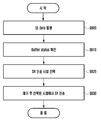
S600 단계에서, 단말이 기지국에게 보내야 할 UL 데이터가 발생한다. S610 단계에서, 상기 단말은 자신의 버퍼 상태(buffer status)를 확인한다.In step S600, the terminal generates UL data to be transmitted to the base station. In step S610, the UE confirms its buffer status.
S620 단계에서, 상기 단말은 확인된 buffer status가 어떤 P-BSI에 대응되는지 확인하고, 확인된 P-BSI에 대응하는 subframe을 선택할 수 있다.In step S620, the UE determines which P-BSI corresponds to the confirmed buffer status, and selects a subframe corresponding to the identified P-BSI.
S630 단계에서, 상기 단말은 현재 시점에서부터 확인된 subframe까지 대기하고 해당 subframe에서 SR을 전송할 수 있다.In step S630, the UE waits until the subframe identified from the current point of time and transmits the SR in the corresponding subframe.
본 발명의 제1 실시예에 소요되는 시간이 총 9 ~ 12 subframe이 소요됨을 알 수 있다. P-BSI을 4단계로 설정한 예에서는 SR 전송 지연이 최대 4 subframe까지 발생할 수 있기 때문이다. 상기 표 1을 참조하면, 제1 실시예에서 소요되는 9 ~ 12 subframe은 제1 방법에서 소요되었던 17 subframe 대비 약 30 ~ 47 % 감소한 값에 해당한다.It can be seen that the total time required for the first embodiment of the present invention is 9 to 12 subframes. In the example of setting P-BSI to 4 levels, SR transmission delay can occur up to 4 subframes. Referring to Table 1, the 9 to 12 subframes used in the first embodiment correspond to the values reduced by about 30 to 47% compared to the 17 subframes used in the first method.
제1 실시예에서는 각 P-BSI에 해당하는 buffer status가 모두 lower limit 및 upper limit이 존재하는 예시에 대해서 설명하였다. 하지만 단말에게 발생하는 트래픽(traffic)의 크기는 랜덤(random)이므로 이에 대응하는 P-BSI가 존재하지 않을 수도 있다. 예를 들어, 단말에게 발생한 traffic의 크기가 2000 bytes인 경우에는 이에 대응하는 P-BSI가 존재하지 않는다. 이러한 경우 단말은 아래와 같이 동작하도록 한다. In the first embodiment, an example in which the buffer status corresponding to each P-BSI exists in the lower limit and the upper limit is described. However, since the size of traffic generated in the UE is random, the corresponding P-BSI may not exist. For example, when the size of traffic generated in the terminal is 2000 bytes, there is no corresponding P-BSI. In this case, the terminal operates as follows.
- 각 SR 자원에 할당된 P-BSI와 상관없이 traffic 발생 시점으로부터 가장 빠른 SR 자원에서 SR을 전송한다.- The SR is transmitted from the earliest SR resource from the point of time of the traffic regardless of the P-BSI allocated to each SR resource.
- 단말에게 발생한 traffic의 크기와 정확하게 일치하지는 않지만 이와 가장 유사한 P-BSI에 해당하는 SR 자원에서 SR을 전송한다.- It transmits the SR in the SR resource corresponding to the P-BSI which does not exactly match the size of the traffic generated in the mobile station.
제안 방안에서 단말은 기존 방안과 마찬가지로 SR 전송 후 수신한 UL grant을 통해서 기지국에게 데이터 및 BSR을 전송하게 된다. 이때 기지국은 단말로부터 BSR을 수신함으로써 단말의 buffer status을 파악할 수 있다. 따라서 단말에게 발생하는 traffic의 크기에 대응하는 P-BSI가 존재하지 않더라도 제안 방안은 문제없이 동작할 수 있다.In the proposed scheme, the MS transmits data and BSR to the BS through the UL grant received after the SR transmission as in the conventional scheme. At this time, the BS can determine the buffer status of the UE by receiving the BSR from the UE. Therefore, even if there is no P-BSI corresponding to the size of traffic generated in the UE, the proposed scheme can operate without any problem.
[제2-1 실시예][Example 2-1]
도 7 내지 도 9는 본 발명의 제2-1 실시예를 설명하기 위한 도면들이다. 상기 제2-1 실시예는 단말의 연속된 SR 전송 횟수와 buffer status 사이의 관계를 설정하고 단말은 자신의 buffer status에 따라서 연속된 SR 전송 횟수를 조절하는 방법에 관한 것이다.Figs. 7 to 9 are views for explaining the second embodiment of the present invention. The embodiment 2-1 described above relates to a method of setting a relation between the number of consecutive SR transmissions and a buffer status of the UE and adjusting the number of consecutive SR transmissions according to the buffer status of the UE.
도 7은 본 발명의 제2-1 실시예에 따른 상향링크 데이터 송수신 방법을 설명하는 도면이다.7 is a view for explaining a method for transmitting and receiving uplink data according to a second embodiment of the present invention.
단말 및 기지국은 RRC signaling 등을 통해서 연속된 SR 전송 횟수(N)에 대응하는 P-BSI을 설정한다. 여기서 P-BSI은 제1 실시예에서의 P-BSI와 동일한 의미를 지닌다. 즉, 단말이 보내야 하는 UL 데이터의 크기가 어느 범위에 속하는가에 대한 정보를 나타낸다.The terminal and the base station set the P-BSI corresponding to the number of consecutive SR transmissions (N) through RRC signaling. Here, P-BSI has the same meaning as P-BSI in the first embodiment. That is, it indicates information on the range in which the size of the UL data to be transmitted by the terminal belongs to.
도 8은 본 발명의 제2-1 실시예에 따라 SR 전송 횟수와 상향링크 데이터 크기의 매핑 관계의 예시를 나타낸다.FIG. 8 illustrates an example of a mapping relationship between an SR transmission count and an uplink data size according to the second embodiment of the present invention.
도 8을 참조하면, 해당 예시에서 연속된 SR 전송 횟수가 1 (N = 1)이라면 단말의 버퍼에 0에서 300 bytes의 UL 데이터가 존재함을 의미하고, 연속된 SR 전송 횟수가 2 (N = 2)이라면 단말의 버퍼에 300에서 600 bytes의 UL 데이터가 존재함을 의미하고, 연속된 SR 전송 횟수가 3 (N = 3)이라면 단말의 버퍼에 600에서 900 bytes의 UL 데이터가 존재함을 의미한다.Referring to FIG. 8, if the number of consecutive SR transmissions is 1 (N = 1) in the example, it means that UL data of 0 to 300 bytes exist in the buffer of the UE. If the number of consecutive SR transmissions is 2 (N = 2 means that there are 300 to 600 bytes of UL data in the buffer of the UE. If the number of consecutive SR transmissions is 3 (N = 3), it means that there are 600 to 900 bytes of UL data in the UE buffer do.
도 7 내지 도 8을 참조하면, 단말이 기지국으로 SR을 1회 전송함으로써 상기 단말은 0에서 300 bytes의 UL 데이터가 존재함을 상기 기지국으로 알릴 수 있다. 또한, 단말이 기지국으로 SR을 2회 전송함으로써 상기 단말은 300에서 600 bytes의 UL 데이터가 존재함을 상기 기지국으로 알릴 수 있다. 또한, 단말이 기지국으로 SR을 3회 전송함으로써 상기 단말은 600에서 900 bytes의 UL 데이터가 존재함을 상기 기지국으로 알릴 수 있다. Referring to FIG. 7 to FIG. 8, the UE transmits an SR to the BS once, thereby informing the BS of UL data of 0 to 300 bytes. In addition, by transmitting the SR twice to the base station, the terminal can notify the base station of the existence of 300 to 600 bytes of UL data. Also, by transmitting the SR to the base station three times, the terminal can notify the base station of the existence of 600 to 900 bytes of UL data.
기지국은 단말의 SR 전송 횟수에 기반하여 상기 단말이 전송하고자 하는 상향링크 데이터의 크기를 파악하고, 상기 상향링크 데이터의 크기에 상응하는 UL grant를 상기 단말로 전송할 수 있다. 상기 단말은 상기 UL grant에 응답하여 상기 상향링크 데이터를 상기 기지국으로 전송할 수 있다. The BS can determine the size of the uplink data to be transmitted by the MS based on the number of SR transmissions of the MS and transmit the UL grant corresponding to the size of the uplink data to the MS. The MS may transmit the uplink data to the BS in response to the UL grant.
단말 및 기지국이 연속된 SR 전송 횟수에 대응하는 P-BSI을 설정하는 동작은 제1 실시예와 유사하게 도 5의 절차를 통해서 이루어진다. 우선, 기지국은 단말에게 최대 연속 SR 전송 횟수에 대한 정보를 제공한다. The operation of setting the P-BSI corresponding to the number of consecutive SR transmissions by the terminal and the base station is performed through the procedure of FIG. 5 similarly to the first embodiment. First, the BS provides information on the maximum number of continuous SR transmissions to the MS.
만약 단말이 기지국에게 보내야 할 UL 데이터가 발생하면 다음과 같이 동작한다.If UL data to be transmitted to the base station occurs, the terminal operates as follows.
단말은 자신의 buffer status을 확인하고, 확인된 buffer status가 어떤 P-BSI에 대응되는지 확인한다. 상기 단말은 확인된 P-BSI에 대응하는 연속된 SR 전송 횟수를 확인한다. 상기 단말은 현재 subframe에서부터 확인된 연속된 SR 전송 횟수만큼 SR을 전송한다.The UE checks its buffer status and checks which P-BSI corresponds to the confirmed buffer status. The UE confirms the number of consecutive SR transmissions corresponding to the identified P-BSI. The UE transmits an SR for the number of consecutive SR transmissions confirmed from the current subframe.
지국은 자신과 P-BSI을 설정한 단말로부터 SR을 수신하면 몇 회 연속 SR이 수신되었는지 확인하여 단말의 buffer status을 파악한다. 그리고 단말의 buffer status을 고려하여 UL scheduling을 수행한다.When the station receives the SR from the terminal that has set the P-BSI and the P-BSI, the station checks the buffer status of the terminal by checking how many times the SR has been received continuously. Then, UL scheduling is performed considering the buffer status of the UE.
기지국의 UL scheduling은 구현 사항이지만 본 발명이 효과를 얻기 위해서는 기지국의 scheduler가 단말의 모든 UL 데이터를 첫 번째 UL grant을 통해서 전송할 수 있을 만큼의 자원을 할당하여 주는 것이 바람직하다.The UL scheduling of the BS is an implementation matter. However, in order to obtain the effect of the present invention, it is preferable that a scheduler of the BS allocates enough resources to transmit all the UL data of the UE through the first UL grant.
도 9는 본 발명의 제2-1 실시예에 따라 SR 전송을 금지하는 타이머를 설정하는 과정을 나타낸다.FIG. 9 shows a process of setting a timer for prohibiting SR transmission according to the second embodiment of the present invention.
LTE을 기반으로 제2-1 실시예를 구현하기 위해서는 표준에서 단말의 연속된 SR 전송이 허용되어야 한다. 현재 LTE 표준에서는 단말이 1회 SR을 전송하면 sr-ProhibitTimer가 작동하여 해당 timer가 만료되기 전까지 다시 SR을 전송할 수 없게 정의되어 있다. In order to implement Embodiment 2-1 based on LTE, consecutive SR transmissions of the terminal in the standard should be allowed. In the current LTE standard, the SR-ProhibitTimer is defined when the UE transmits an SR once, and it is defined that the SR can not be transmitted again until the timer expires.
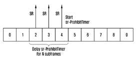
따라서 제2-1 실시예에서는 단말의 연속된 SR 전송이 허용되도록 sr-ProhibitTimer의 작동 시작 시점이 도 9와 같이 변경되어야 한다.Therefore, in the second embodiment, the starting point of operation of the sr-ProhibitTimer should be changed as shown in FIG. 9 so that continuous SR transmission of the terminal is allowed.
- sr-ProhibitTimer 작동 시작 시점 = 첫 SR 전송 시점으로부터 최대 연속 SR 전송 횟수만큼 지연된 시점- sr-ProhibitTimer Start of operation = delayed by the maximum number of consecutive SR transmissions from the first SR transmission point
-
도 7 및 도 8에서는 최대 연속 SR 전송 횟수가 3으로 설정되어 있기 때문에 도 9와 같이 subframe 2에서 첫 SR 전송이 이루어진 경우 3 subframe이 지연된 시점인 subframe 5부터 sr-ProhibitTimer가 작동하기 시작한다.-
In FIGS. 7 and 8, since the maximum number of consecutive SR transmissions is set to 3, when the first SR transmission is performed in
[제2-2 실시예][Example 2-2]
도 10 내지 도 11은 본 발명의 제2-2 실시예를 설명하기 위한 도면들이다. 상기 제2-2 실시예는 단말의 일정 구간 내 SR 전송을 비트맵(bitmap)으로 형성한 후 해당 bitmap과 버퍼 상태(buffer status) 사이의 관계를 설정하여 활용하는 방법이다. 단말은 자신의 buffer status에 따라서 SR 전송을 제어한다.10 to 11 are views for explaining a second embodiment of the present invention. The embodiment 2-2 is a method of forming a bitmap of an SR transmission within a certain period of a terminal and then setting and using a relation between the corresponding bitmap and a buffer status. The terminal controls the SR transmission according to its buffer status.
도 10은 본 발명의 제2-2 실시예에 따른 상향링크 데이터 송수신 방법을 설명하는 도면이다.10 is a view for explaining a method for transmitting and receiving uplink data according to a second embodiment of the present invention.
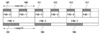
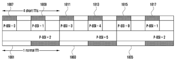
도 10을 참조하면, 일정 구간 내 SR 전송을 bitmap으로 형성하는 구성이 개시되어 있다. 만약 단말에 2 subframe 동안 SR 전송이 허용된다면 SR 전송의 유무에 따라 00, 01, 10, 11의 bitmap이 표현 가능하다. 예를 들어, 첫 번째 서브프레임에서 SR이 전송되고 두 번째 서브프레임에서 SR이 전송되지 않으면, 상기 비트맵은 "10"으로 표현될 수 있다.Referring to FIG. 10, a configuration for forming SR transmissions within a predetermined interval as a bitmap is disclosed. If the terminal is allowed to transmit SRs during 2 subframes, bitmaps of 00, 01, 10, and 11 can be expressed according to the presence or absence of SR transmission. For example, if the SR is transmitted in the first sub-frame and the SR is not transmitted in the second sub-frame, the bitmap may be represented by "10 ".
또한, 만약 단말이 3 subframe 동안 SR 전송이 허용된다면 마찬가지로 000, 001, 010, 011, 100, 101, 110, 111의 bitmap이 표현 가능하다. 예를 들어, 첫 번째 서브프레임에서 SR이 전송되고 두 번째 서브프레임에서 SR이 전송되지 않고 세 번째 서브프레임에서 SR이 전송되면, 상기 비트맵은 "101"로 표현될 수 있다.Also, if the terminal is allowed to transmit SRs during 3 subframes, bitmaps of 000, 001, 010, 011, 100, 101, 110 and 111 can be expressed. For example, if SR is transmitted in the first subframe, SR is not transmitted in the second subframe, and SR is transmitted in the third subframe, the bitmap may be represented by "101 ".
단말 및 기지국은 RRC signaling 등을 통해서 일정 구간 내 SR 전송 기반 bitmap에 대응하는 P-BSI을 설정한다. 여기서 P-BSI은 제1 실시예에서의 P-BSI와 동일한 의미를 지닌다. 즉, 단말이 보내야 하는 UL 데이터의 크기가 어느 범위에 속하는가에 대한 정보를 나타낸다.The terminal and the base station set the P-BSI corresponding to the SR transmission-based bitmap within a certain interval through the RRC signaling. Here, P-BSI has the same meaning as P-BSI in the first embodiment. That is, it indicates information on the range in which the size of the UL data to be transmitted by the terminal belongs to.
도 11은 본 발명의 제2-2 실시예에 따라 SR 전송과 관련된 비트맵와 상향링크 데이터의 매핑 관계의 예시를 나타낸다. 도 11을 참조하면, bitmap에 단말의 buffer status을 대응시킬 수 있다. 11 illustrates an example of a mapping relationship between a bitmap and uplink data related to an SR transmission according to a second embodiment of the present invention. Referring to FIG. 11, a buffer status of a terminal can be associated with a bitmap.
도 11을 참조하면, 3 subframe 내 SR 전송 기반 bitmap이 100 (SR 전송 on → off → off)이라면 단말의 buffer에 1200에서 1500 byte의 UL 데이터가 존재함을 의미한다.Referring to FIG. 11, if the SR transmission based bitmap in 3 subframes is 100 (SR transmission on → off → off), it means that UL data of 1200 to 1500 bytes exist in the buffer of the UE.
단말 및 기지국이 일정 구간 내 SR 전송 기반 bitmap에 대응하는 P-BSI을 설정하는 동작은 제1 실시예와 유사하게 도 5의 절차를 통해서 이루어진다. 기지국은 단말에게 SR 전송이 수행되는 일정 구간에 대한 정보를 제공한다.The operation of setting the P-BSI corresponding to the SR transmission-based bitmap within the predetermined interval by the terminal and the base station is performed through the procedure of FIG. 5 similarly to the first embodiment. The base station provides information on a certain period in which the SR transmission is performed to the UE.
만약 단말이 기지국에게 보내야 할 UL 데이터가 발생하면 다음과 같이 동작한다.If UL data to be transmitted to the base station occurs, the terminal operates as follows.
단말은 자신의 buffer status을 확인하고, 확인된 buffer status가 어떤 P-BSI에 대응되는지 확인한다.상기 단말은 확인된 P-BSI에 대응하는 일정 구간 내 SR 전송 기반 bitmap을 확인한다. 상기 단말은 현재 subframe에서부터 일정 구간 동안 확인된 bitmap과 같이 SR을 전송한다.The UE checks its buffer status and confirms which P-BSI corresponds to the confirmed buffer status. The UE checks the SR transmission-based bitmap within a predetermined interval corresponding to the confirmed P-BSI. The terminal transmits an SR as a bitmap that has been checked for a predetermined period from the current subframe.
만약 단말의 buffer status가 1200에서 1500 byte 사이인 경우 단말은 앞으로 3 subframe 동안 SR 전송을 on → off → off 형태로 수행한다.If the buffer status of the UE is between 1200 and 1500 bytes, the UE shall perform SR transmission for 3 subframes in the order of on → off → off.
기지국은 자신과 P-BSI을 설정한 단말로부터 SR을 수신하면 일정 구간 동안 어떤 bitmap 형태로 SR이 수신되었는지 확인하여 단말의 buffer status을 파악한다. 그리고 단말의 buffer status을 고려하여 UL scheduling을 수행한다.When the base station receives the SR from the P-BSI and the P-BSI, the BS checks the bit status of the received SR to determine the buffer status of the UE. Then, UL scheduling is performed considering the buffer status of the UE.
기지국의 UL scheduling은 구현 사항이지만 본 발명이 효과를 얻기 위해서는 기지국의 scheduler가 단말의 모든 UL 데이터를 첫 번째 UL grant을 통해서 전송할 수 있을 만큼의 자원을 할당하여 주는 것이 바람직하다.The UL scheduling of the BS is an implementation matter. However, in order to obtain the effect of the present invention, it is preferable that a scheduler of the BS allocates enough resources to transmit all the UL data of the UE through the first UL grant.
[제3 실시예][Third Embodiment]
도 12 내지 도 13은 본 발명의 제3 실시예를 설명하기 위한 도면들이다. 상기 제3 실시예는 다수의 bit으로 구성된 SR 신호를 이용하여 상향링크 송수신 절차를 수행하는 방법에 관한 것이다.12 to 13 are views for explaining a third embodiment of the present invention. The third embodiment relates to a method for performing an uplink transmission / reception procedure using an SR signal composed of a plurality of bits.
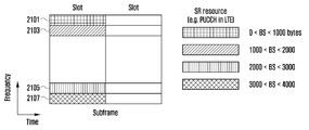
도 12는 본 발명의 제3 실시예에 따른 상향링크 데이터 송수신 방법을 설명하는 도면이다. 도 12를 참조하면, PUCCH 포맷 4에서 버퍼 상태 정보를 나타내는 SR을 다수의 bit으로 설정할 수 있다.12 is a view for explaining a method of transmitting and receiving uplink data according to a third embodiment of the present invention. Referring to FIG. 12, in the
현재 LTE는 SR 신호로써 on-off keying based signaling을 사용한다. 이와 달리 본 발명에서는 SR 신호로써 다수의 bit으로 구성된 SR 신호를 제안한다. 이는 단말의 SR bit와 buffer status 사이의 관계를 설정하고 단말은 자신의 buffer status에 따라서 특정 SR bit을 전송하는 방법이다. 이를 위해서 다양한 code, sequence 등이 활용될 수 있다. 본 발명은 이에 활용되는 SR bit, code, sequence 등에 한정되지 않는다.Currently, LTE uses on-off keying based signaling as an SR signal. In contrast, the present invention proposes an SR signal composed of a plurality of bits as an SR signal. This establishes the relationship between the SR bit and the buffer status of the UE, and the UE transmits a specific SR bit according to its buffer status. Various codes and sequences can be used for this purpose. The present invention is not limited to SR bits, codes, sequences, and the like used in the present invention.
단말 및 기지국은 RRC signaling 등을 통해서 SR bit에 대응하는 P-BSI을 설정한다. 여기서 P-BSI은 제1 실시예에서의 P-BSI와 동일한 의미를 지닌다. 즉, 단말이 보내야 하는 UL 데이터의 크기가 어느 범위에 속하는가에 대한 정보를 나타낸다.The terminal and the base station set the P-BSI corresponding to the SR bit through the RRC signaling. Here, P-BSI has the same meaning as P-BSI in the first embodiment. That is, it indicates information on the range in which the size of the UL data to be transmitted by the terminal belongs to.
도 13a는 본 발명의 제3-1 실시예에 따라 다수의 비트로 구성된 SR과 상향링크 데이터의 매핑 관계의 예시를 나타낸다.FIG. 13A shows an example of a mapping relationship between an SR composed of a plurality of bits and uplink data according to the embodiment 3-1 of the present invention.
도 13a를 참조하면, 해당 예시에서 SR bit이 "0100"이라면 단말의 buffer에 2000에서 2500 byte의 UL 데이터가 존재함을 의미한다.Referring to FIG. 13A, if the SR bit is "0100 " in the example, it means that there are 2000 to 2500 bytes of UL data in the buffer of the UE.
단말 및 기지국이 SR bit에 대응하는 P-BSI을 설정하는 동작은 제1 실시예와 유사하게 도 5의 절차를 통해서 이루어진다. 기지국은 단말에게 SR 신호가 몇 bit으로 구성되어 있는지에 대한 정보를 제공한다.The operation of the terminal and the base station to set the P-BSI corresponding to the SR bit is performed through the procedure of FIG. 5 similarly to the first embodiment. The base station provides the terminal with information on how many bits the SR signal is composed of.
만약 단말이 기지국에게 보내야 할 UL 데이터가 발생하면 다음과 같이 동작한다. 단말은 자신의 buffer status을 확인하고, 확인된 buffer status가 어떤 P-BSI에 대응되는지 확인한다. 상기 단말은 확인된 P-BSI에 대응하는 SR bit을 확인하고, 확인된 SR bit으로 구성된 SR 신호를 전송한다.If UL data to be transmitted to the base station occurs, the terminal operates as follows. The UE checks its buffer status and checks which P-BSI corresponds to the confirmed buffer status. The UE confirms the SR bit corresponding to the confirmed P-BSI and transmits the SR signal composed of the confirmed SR bits.
상기
단말이 보내야 할 UL 데이터가 2000에서 2500 byte 범위 내에 존재하면 단말은 SR bit 0100으로 구성된 SR 신호를 전송한다.remind
If the UL data to be transmitted by the UE is within the range of 2000 to 2500 bytes, the UE transmits an SR signal composed of
본 발명에서 단말이 다수의 bit으로 구성된 SR 신호를 전송할 때 BPSK, QPSK, QAM 등 다양한 modulation 방법이 적용될 수 있다. 본 발명은 이를 전송할 때 적용되는 modulation 및 coding 방법에 의해서 한정되지 않는다.In the present invention, various modulation methods such as BPSK, QPSK, and QAM may be applied when a terminal transmits an SR signal composed of a plurality of bits. The present invention is not limited by the modulation and coding methods applied in the transmission.
기지국은 SR 신호를 수신하고 SR bit을 확인하여 단말의 buffer status을 파악한다. 그리고 단말의 buffer status을 고려하여 UL scheduling을 수행한다.The base station receives the SR signal and checks the SR bit to determine the buffer status of the UE. Then, UL scheduling is performed considering the buffer status of the UE.
본 발명에서는 scheduling request 신호가 다수의 bit으로 구성되어 있을 때 해당 bit의 조합을 단말의 buffer status에 대응시키는 방안을 제안하였다. 따라서 기지국이 scheduling request 신호를 수신하였을 때 단말의 UL 전송 필요 여부뿐만 아니라 buffer status 정보까지 파악할 수 있도록 하여 기지국이 단말에게 적합한 크기의 UL 자원을 신속히 할당할 수 있도록 하였다. 이와 동일한 원리로 본 발명에서는 scheduling request 신호를 구성하는 다수 bit의 조합을 buffer status 뿐만 아니라 다양한 정보에 대응될 수 있도록 한다. 이는 다음의 예를 포함한다.In the present invention, when a scheduling request signal is composed of a plurality of bits, a combination of corresponding bits is associated with a buffer status of the UE. Therefore, when the BS receives the scheduling request signal, it can grasp not only the necessity of UL transmission but also the buffer status information, so that the BS can allocate the UL resource of the proper size to the UE quickly. According to the same principle, in the present invention, a combination of a plurality of bits constituting a scheduling request signal can correspond to various information as well as a buffer status. This includes the following example.
- Scheduling request 신호를 구성하는 다수 bit의 조합은 단말이 전송하고자 하는 traffic의 종류에 대응될 수 있다.The combination of the bits constituting the scheduling request signal may correspond to the type of traffic that the terminal desires to transmit.
● 여기서 traffic 종류란 voice, video, text message, FTP, HTTP 등이 될 수 있다.● Traffic type can be voice, video, text message, FTP, HTTP, etc.
● 기지국이 특정 traffic 종류에 대응하는 scheduling request 신호를 단말로부터 수신하면 기지국은 단말이 해당 traffic을 전송하는데 적합한 시간/주파수/공간/numerology/TTI 자원을 단말에게 할당한다.When a base station receives a scheduling request signal corresponding to a specific traffic type from a mobile station, the base station allocates a time / frequency / space / numerology / TTI resource suitable for the mobile station to transmit the traffic.
- Scheduling request 신호를 구성하는 다수 bit의 조합은 단말이 전송하고자 하는 UL data을 생성한 서비스 또는 application의 종류에 대응될 수 있다.The combination of the bits constituting the scheduling request signal may correspond to the type of service or application that generated the UL data to be transmitted by the UE.
● 여기서 서비스 또는 application 종류란 예를 들면 SNS (Social Networking Service), V2V (Vehicle-to-Vehicle), V2I (Vehicle-to-Infra structure), V2P (Vehicle-to-Person), 뉴스 등이 될 수 있다.Here, the service or application type can be, for example, a social networking service (SNS), a vehicle-to-vehicle (V2V), a vehicle-to-infra structure (V2I), a vehicle- have.
● 기지국이 특정 서비스 또는 application 종류에 대응하는 scheduling request 신호를 단말로부터 수신하면 기지국은 단말이 해당 서비스 또는 application으로부터 발생한 data을 전송하는데 적합한 시간/주파수/공간/numerology/TTI 자원을 단말에게 할당한다.When a base station receives a scheduling request signal corresponding to a specific service or application type from a mobile station, the base station allocates time / frequency / space / numerology / TTI resources suitable for transmitting data generated from the corresponding service or application.
- Scheduling request 신호를 구성하는 다수 bit의 조합은 단말이 전송하고자 하는 UL data가 속한 logical channel에 대응될 수 있다.The combination of the bits constituting the scheduling request signal may correspond to the logical channel to which the UL data to be transmitted by the UE belongs.
● 기지국이 특정 logical channel에 대응하는 scheduling request 신호를 단말로부터 수신하면 기지국은 단말이 해당 logical channel에서 발생한 data을 전송하는데 적합한 시간/주파수/공간/numerology/TTI 자원을 단말에게 할당한다.When a base station receives a scheduling request signal corresponding to a specific logical channel from a mobile station, the base station allocates time / frequency / space / numerology / TTI resources suitable for transmitting data generated in the logical channel to the mobile station.
- Scheduling request 신호를 구성하는 다수 bit의 조합은 단말이 전송하고자 하는 UL data가 속한 logical channel group에 대응될 수 있다.The combination of the bits constituting the scheduling request signal may correspond to the logical channel group to which the UL data to be transmitted by the UE belongs.
● 기지국이 특정 logical channel group에 대응하는 scheduling request 신호를 단말로부터 수신하면 기지국은 단말이 해당 logical channel group에서 발생한 data을 전송하는데 적합한 시간/주파수/공간/numerology/TTI 자원을 단말에게 할당한다.When a base station receives a scheduling request signal corresponding to a specific logical channel group from a mobile station, the base station allocates time / frequency / space / numerology / TTI resources suitable for transmitting data generated in the logical channel group.
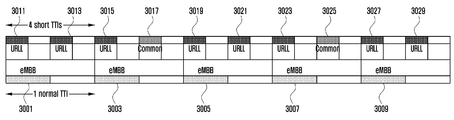
● Scheduling request 신호를 구성하는 다수 bit의 조합은 단말이 전송하고자 하는 UL data가 속한 network slice에 대응될 수 있다.여기서 network slice란 예를 들면 eMBB (enhanced Mobile BroadBand) slice, URLLC (Ultra Reliable & Low Latency Communication) slice, mMTC (massive Machine Type Communication) slice 등이 될 수 있다.The combination of the multiple bits constituting the scheduling request signal may correspond to a network slice to which UL data to be transmitted by the UE belongs. Herein, the network slice refers to an enhanced Mobile Broadband (eMBB) slice, an Ultra Reliable & Low Latency communication slice, massive machine type communication (mMTC) slice, and the like.
● 기지국이 특정 network slice에 대응하는 scheduling request 신호를 단말로부터 수신하면 기지국은 단말이 해당 network slice에서 발생한 data을 전송하는데 적합한 시간/주파수/공간/numerology/TTI 자원을 단말에게 할당한다.When the BS receives a scheduling request signal corresponding to a specific network slice from the MS, the BS allocates time / frequency / space / numerology / TTI resources suitable for transmitting data generated in the corresponding network slice to the MS.
- Scheduling request 신호를 구성하는 다수 bit의 조합은 단말이 전송하고자 하는 UL data의 송수신에 적합한 numerology에 대응될 수 있다.The combination of the bits constituting the scheduling request signal may correspond to a numerology suitable for transmission / reception of UL data to be transmitted by the UE.
● 여기서 numerology란 subcarrier spacing 등을 의미하는데 15*2m kHz, 즉 15 kHz (m = 0), 30 kHz (m = 1), 60 kHz (m = 2), 120 kHz (m = 3) 등이 될 수도 있고 15*n kHz, 즉 15 kHz (n = 1), 30 kHz (n = 2), 45 kHz (n = 3), 60 kHz (n = 4) 등 다양한 방법으로 표현되는 값 중 일부가 될 수 있다.● Here, numerology means subcarrier spacing and so on. It is 15 * 2m kHz, that is 15kHz (m = 0), 30kHz (m = 1), 60kHz (m = 2), 120kHz (N = 1), 30 kHz (n = 2), 45 kHz (n = 3), and 60 kHz (n = 4) .
● 기지국이 특정 numerology에 대응하는 scheduling request 신호를 단말로부터 수신하면 기지국은 해당 numerology에 대응하는 시간/주파수/공간 자원을 단말에게 할당한다.When a base station receives a scheduling request signal corresponding to a particular numerology from a terminal, the base station allocates time / frequency / spatial resources corresponding to the corresponding numerology to the terminal.
- Scheduling request 신호를 구성하는 다수 bit의 조합은 단말이 전송하고자 하는 UL data의 송수신에 적합한 TTI 길이에 대응될 수 있다.The combination of the bits constituting the scheduling request signal may correspond to a TTI length suitable for transmission / reception of UL data to be transmitted by the UE.
● 여기서 TTI 길이란 subframe 길이, slot 길이, mini-slot 길이, PDCCH와 같은 제어 채널의 전송 주기 등을 의미하는데 예를 들면 1/2m ms, 즉 1 ms (m = 0), 0.5 ms (m = 1), 0.25 ms (m = 2), 0.125 ms (m = 3) 등 다양한 방법으로 표현되는 값 중 일부가 될 수 있다.● Here, TTI length means subframe length, slot length, mini-slot length, transmission period of control channel such as PDCCH, for example 1 / 2m ms, 1), 0.25 ms (m = 2), and 0.125 ms (m = 3).
● 기지국이 특정 TTI 길이에 대응하는 scheduling request 신호를 단말로부터 수신하면 기지국은 해당 TTI 길이에 대응하는 시간/주파수/공간 자원을 단말에게 할당한다.When a base station receives a scheduling request signal corresponding to a specific TTI length from a mobile station, the base station allocates a time / frequency / spatial resource corresponding to the corresponding TTI length to the mobile station.
- Scheduling request 신호를 구성하는 다수 bit의 조합은 단말이 전송하고자 하는 UL data의 latency 요구 사항에 대응될 수 있다.- The combination of multiple bits constituting the scheduling request signal may correspond to the latency requirement of UL data to be transmitted by the UE.
● 여기서 latency 요구 사항은 시간 단위 (s 또는 ms) 또는 subframe 단위 등으로 표현될 수 있다. 이는 (i) 단말이 scheduling request 신호를 전송하는 시점부터 기지국으로부터 UL 자원을 할당 받는 시점 사이의 최대 허용 시간 또는 (ii) 단말이 scheduling request 신호를 전송하는 시점부터 단말이 UL data을 전송하는 시점 사이의 최대 허용 시간 등을 의미할 수 있다.● The latency requirement can be expressed in time units (s or ms) or subframe units. (I) the maximum allowed time between when the UE transmits the scheduling request signal and when the UL resource is allocated from the BS, or (ii) when the UE transmits the UL data, The maximum permissible time of the mobile terminal, and the like.
● 기지국이 특정 latency 요구 사항에 대응하는 scheduling request 신호를 단말로부터 수신하면 기지국은 단말이 UL data 전송 시 latency 요구 사항을 만족하는데 적합한 시간/주파수/공간/numerology/TTI 자원을 단말에게 할당한다.When the BS receives a scheduling request signal corresponding to a specific latency requirement from the MS, the BS allocates time / frequency / space / numerology / TTI resources suitable for the terminal to satisfy the latency requirement when transmitting UL data.
- Scheduling request 신호를 구성하는 다수 bit의 조합은 단말이 전송하고자 하는 UL data의 QCI (QoS Class Identifier)에 대응될 수 있다.The combination of the bits constituting the scheduling request signal may correspond to the QCI (QoS Class Identifier) of UL data to be transmitted by the UE.
● 여기서 QCI는 아래의 표와 같이 LTE에 정의되어 있는 QCI을 포함할 수 있다.● QCI can include QCI defined in LTE as shown in the table below.

● 기지국이 특정 QCI에 대응하는 scheduling request 신호를 단말로부터 수신하면 기지국은 단말이 해당 QCI을 만족하는데 적합한 시간/주파수/공간/numerology/TTI 자원을 단말에게 할당한다.When a base station receives a scheduling request signal corresponding to a specific QCI from a terminal, the base station allocates time / frequency / space / numerology / TTI resources suitable for the terminal to satisfy the corresponding QCI.
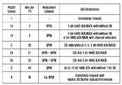
본 발명에서는 scheduling request 신호가 다수의 bit으로 구성되어 있을 때 해당 bit의 조합을 단말의 buffer status에 대응시키는 방법을 제안하였다. 또한 <추가 1>에서 scheduling request 신호를 구성하는 다수 bit의 조합이 다양한 정보에 대응될 수 있도록 하였다. 이러한 확장을 본 발명에서 제안한 모든 방법에 적용하고자 한다.In the present invention, when a scheduling request signal is composed of a plurality of bits, a combination of corresponding bits is associated with a buffer status of the UE. In addition, in <
본 발명에서는 다수의 bit으로 구성된 scheduling request 신호를 사용하는 방법 외에도 (a) SR 신호를 서로 다른 시간 또는 주파수 또는 code 자원을 통해서 전송하는 방법 및 (b) SR 신호를 연속적으로 전송하는 방법을 제안하였다. 따라서 본 발명에서는 서로 다른 SR 시간 또는 주파수 또는 code 자원 각각이 단말의 buffer status, UL traffic 종류, service 또는 application 종류, logical channel, logical channel group, network slice, numerology, TTI 길이, latency 요구 사항, QoS class identifier 등에 대응될 수 있다. 또한 SR 신호의 연속 전송 횟수가 단말의 buffer status, UL traffic 종류, service 또는 application 종류, logical channel, logical channel group, network slice, numerology, TTI 길이, latency 요구 사항, QoS class identifier 등에 대응될 수 있다. 이러한 대응 관계가 도 13c에 표현되어 있다.The present invention proposes a method of transmitting a SR signal through different time or frequency or code resources and (b) a method of continuously transmitting an SR signal in addition to a method of using a scheduling request signal composed of a plurality of bits . Therefore, according to the present invention, each of different SR time, frequency, or code resources is allocated to the buffer status, UL traffic type, service or application type, logical channel, logical channel group, network slice, numerology, TTI length, identifier and so on. Also, the number of consecutive transmissions of the SR signal may correspond to the buffer status, UL traffic type, service or application type, logical channel, logical channel group, network slice, numerology, TTI length, latency requirement and QoS class identifier of the UE. This correspondence is shown in Fig. 13C.
기지국의 UL scheduling은 구현 사항이지만 본 발명이 효과를 얻기 위해서는 기지국의 scheduler가 단말의 모든 UL 데이터를 첫 번째 UL grant을 통해서 전송할 수 있을 만큼의 자원을 할당하여 주는 것이 바람직하다.The UL scheduling of the BS is an implementation matter. However, in order to obtain the effect of the present invention, it is preferable that a scheduler of the BS allocates enough resources to transmit all the UL data of the UE through the first UL grant.
지금까지 본 발명을 설명할 때 매 subframe 마다 단말에게 할당된 SR 자원이 있음을 가정하였다. 하지만 본 발명은 매 subframe 마다 단말에게 할당된 SR 자원이 존재하지 않더라도 SR 자원마다 P-BSI을 할당함으로써 적용할 수 있다. In the description of the present invention, it is assumed that there is an SR resource allocated to the UE for each subframe. However, the present invention can be applied by allocating P-BSI for each SR resource even if there is no SR resource allocated to the UE for each subframe.
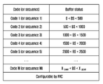
도 13b는 본 발명의 제3-2 실시예에 따라 코드 기반 SR과 상향링크 데이터의 매핑 관계의 예시를 나타낸다.FIG. 13B shows an example of a mapping relationship between a code-based SR and uplink data according to the embodiment 3-2 of the present invention.
도 13b를 참조하면, code 기반 SR을 활용하여 자신의 buffer status에 따라서 특정 code를 전송할 수 있다. 예컨대, Code 2가 SR로 사용된다면 단말의 buffer에 500에서 1000 byte의 UL 데이터가 존재함을 의미한다. Referring to FIG. 13B, it is possible to transmit a specific code according to its buffer status using a code-based SR. For example, if
단말 및 기지국은 RRC signaling 등을 통해서 code 기반 SR에 대응하는 P-BSI을 설정한다. 여기서 P-BSI는 제1 실시예에서의 P-BSI와 동일한 의미를 지닌다. 즉, 단말이 보내야 하는 UL 데이터의 크기가 어느 범위에 속하는가에 대한 정보를 나타낸다.The terminal and the base station set the P-BSI corresponding to the code-based SR through RRC signaling. Here, P-BSI has the same meaning as P-BSI in the first embodiment. That is, it indicates information on the range in which the size of the UL data to be transmitted by the terminal belongs to.
단말 및 기지국이 각 code에 대응하는 P-BSI을 설정하는 동작은 제안 동작 1과 같이 아래의 절차를 통해서 이루어진다.The operation of setting the P-BSI corresponding to each code by the terminal and the base station is performed as follows in the
기지국은 단말에게 SR-based BS level 수 및 각 BS level에 대응하는 code를 할당한다. 단말은 각 BS level에 대응하는 buffer status의 범위를 기지국에게 알린다.The BS allocates the number of SR-based BS levels and code corresponding to each BS level to the MS. The terminal informs the base station of the range of the buffer status corresponding to each BS level.
만약 단말이 기지국에게 보내야 할 UL 데이터가 발생하면 다음과 같이 동작한다. 단말은 자신의 buffer status을 확인하고, 확인된 buffer status가 어떤 P-BSI에 대응되는지 확인한다. 상기 단말은 확인된 P-BSI에 대응하는 SR용 code을 확인하고, 확인된 code로 구성된 SR 신호를 전송한다.If UL data to be transmitted to the base station occurs, the terminal operates as follows. The UE checks its buffer status and checks which P-BSI corresponds to the confirmed buffer status. The MS confirms the SR code corresponding to the identified P-BSI and transmits the SR signal composed of the confirmed code.
기지국은 SR용 code를 수신하고 이를 확인하여 단말의 buffer status을 파악한다. 그리고 단말의 buffer status을 고려하여 UL scheduling을 수행한다.The base station receives the SR code and checks it to determine the buffer status of the terminal. Then, UL scheduling is performed considering the buffer status of the UE.
기지국의 UL scheduling은 구현 사항이지만 본 발명이 효과를 얻기 위해서는 기지국의 scheduler가 단말의 모든 UL 데이터를 첫 번째 UL grant을 통해서 전송할 수 있을 만큼의 자원을 할당하여 주는 것이 바람직하다.The UL scheduling of the BS is an implementation matter. However, in order to obtain the effect of the present invention, it is preferable that a scheduler of the BS allocates enough resources to transmit all the UL data of the UE through the first UL grant.
도 14 내지 도 20은 본 발명의 실시예들에 따라 SR 자원에 버퍼 상태 인덱스를 설정하는 과정을 설명하는 도면들이다.FIGS. 14 through 20 are diagrams illustrating a process of setting a buffer status index on an SR resource according to embodiments of the present invention.
도 14는 본 발명의 실시예에 따라 SR 자원에 버퍼 상태 인덱스를 설정하는 과정을 나타낸다. 이때, 상기 버퍼 상태 인덱스는 앞서 설명한 P-BSI를 의미한다.FIG. 14 illustrates a process of setting a buffer status index on an SR resource according to an embodiment of the present invention. At this time, the buffer status index means the P-BSI described above.
도 14에서는 단말에게 2 subframe 마다 SR 자원이 할당된 상태를 보여준다. subframe 내에서 할당되는 SR 자원들(1401 ~ 1411) 각각에 순차적으로 P-BSI가 할당될 수 있다.FIG. 14 shows a state in which an SR resource is allocated to the terminal every 2 subframes. P-BSI can be sequentially allocated to each of the
도 15는 본 발명의 다른 실시예에 따라 SR 자원에 버퍼 상태 인덱스를 설정하는 과정을 나타낸다. FIG. 15 illustrates a process of setting a buffer status index on an SR resource according to another embodiment of the present invention.
도 15에서는 normal TTI와 short TTI가 하나의 subframe에 공존하고 1 normal TTI 마다 SR 자원(1501 ~ 1505)이 할당되고, 2 short TTI 마다 SR 자원(1507 ~ 1517)이 할당된 상태를 보여준다. 만약 총 P-BSI level의 수가 6인 경우에는 하나의 subframe 내에서 short TTI의 SR 자원(예컨대, 1507, 1509)에 P-BSI가 우선적으로 할당되고, normal TTI의 SR 자원(예컨대, 1501)에 P-BSI가 나중에 할당될 수 있다.In FIG. 15, normal TTIs and short TTIs coexist in one subframe,
도 16은 본 발명의 또 다른 실시예에 따라 SR 자원에 버퍼 상태 인덱스를 설정하는 과정을 나타낸다.16 illustrates a process of setting a buffer status index on an SR resource according to another embodiment of the present invention.
도 16에서는 normal TTI와 short TTI가 하나의 subframe에 공존하고 1 normal TTI 마다 SR 자원(1601 ~ 1605)이 할당되고, 2 short TTI 마다 SR 자원(1604 ~ 1617)이 할당된 상태를 보여준다. 만약 총 P-BSI level의 수가 6인 경우에는 하나의 subframe 내에서 normal TTI의 SR 자원(예컨대, 1601)에 P-BSI가 우선적으로 할당되고, short TTI의 SR 자원(예컨대, 1607, 1609)에 P-BSI가 나중에 할당될 수 있다.In FIG. 16, normal TTIs and short TTIs coexist in one subframe, and
도 17은 본 발명의 또 다른 실시예에 따라 SR 자원에 버퍼 상태 인덱스를 설정하는 과정을 나타낸다.17 illustrates a process of setting a buffer status index on an SR resource according to another embodiment of the present invention.
도 17은 normal TTI와 short TTI가 하나의 subframe에 공존하고 1 normal TTI 마다 SR 자원(1701 ~ 1705)이 할당되고, 2 short TTI 마다 SR 자원(1707 ~ 1717)이 할당된 상태를 보여준다. 17 shows a state in which normal TTIs and short TTI coexist in one subframe and
만약 총 P-BSI level의 수가 6인 경우에는 하나의 subframe 내에서 시간적으로 먼저 존재하는 SR 자원 중 short TTI의 SR 자원(예컨대, 1707)에 P-BSI가 우선적으로 할당되고 normal TTI의 SR 자원(예컨대, 1701)에 P-BSI가 나중에 할당될 수 있다. If the total number of P-BSI levels is 6, P-BSI is preferentially allocated to an SR resource (for example, 1707) of a short TTI among SR resources that exist in time in one subframe in advance, and SR resources For example, P-BSI may be assigned to 1701 later.
도 18은 본 발명의 또 다른 실시예에 따라 SR 자원에 버퍼 상태 인덱스를 설정하는 과정을 나타낸다.18 shows a process of setting a buffer status index on an SR resource according to another embodiment of the present invention.
도 18은 normal TTI와 short TTI가 하나의 subframe에 공존하고 1 normal TTI 마다 SR 자원(1801 ~ 1805)이 할당되고, 2 short TTI 마다 SR 자원(1807 ~ 1817)이 할당된 상태를 보여준다. 18 shows a state in which normal TTIs and short TTI coexist in one subframe and
만약 총 P-BSI level의 수가 6인 경우에는 시간적으로 먼저 존재하는 SR 자원(예컨대, 1807, 1809)에 P-BSI가 우선적으로 할당되고 시간적으로 나중에 존재하는 SR 자원에 P-BSI(예컨대, 1801)가 나중에 할당될 수 있다.If the total number of P-BSI levels is 6, then P-BSI is preferentially allocated to SR resources (e.g., 1807 and 1809) that are present in time, and P-BSI ) May be assigned later.
도 19는 본 발명의 또 다른 실시예에 따라 SR 자원에 버퍼 상태 인덱스를 설정하는 과정을 나타낸다.FIG. 19 shows a process of setting a buffer status index on an SR resource according to another embodiment of the present invention.
도 19에서는 normal TTI와 short TTI가 하나의 subframe에 공존하고 1 normal TTI 마다 SR 자원(1901 ~ 1905)이 할당되고, 2 short TTI 마다 SR 자원(1907 ~ 1917)이 할당된 상태를 보여준다. 만약 총 P-BSI level의 수가 4인 경우에는 short TTI에 존재하는 SR 자원(예컨대, 1907, 1909)에는 P-BSI가 할당되고 normal TTI에 존재하는 SR 자원(예컨대, 1901)에는 P-BSI가 할당되지 않지 않을 수 있다.FIG. 19 shows a state in which normal TTIs and short TTI coexist in one subframe and SR resources (1901 to 1905) are allocated to one normal TTI and SR resources (1907 to 1917) are allocated to two short TTIs. If the total number of P-BSI levels is 4, P-BSI is allocated to SR resources (e.g., 1907 and 1909) existing in short TTIs and P-BSI is allocated to SR resources (e.g., 1901) It may not be allocated.
도 20은 본 발명의 또 다른 실시예에 따라 SR 자원에 버퍼 상태 인덱스를 설정하는 과정을 나타낸다.FIG. 20 illustrates a process of setting a buffer state index on an SR resource according to another embodiment of the present invention.
도 20에서는 normal TTI와 short TTI가 하나의 subframe에 공존하고 1 normal TTI 마다 SR 자원(2001 ~ 2005)이 할당되고, 2 short TTI 마다 SR 자원(2007 ~ 2017)이 할당된 상태를 보여준다. 만약 총 P-BSI level의 수가 4인 경우에는 위의 그림과 같이 normal TTI에 존재하는 SR 자원(예컨대, 2001)에는 P-BSI가 할당되고 short TTI에 존재하는 SR 자원(예컨대, 2007, 2009)에는 P-BSI가 할당되지 않지 않을 수 있다.In FIG. 20, the normal TTI and the short TTI coexist in one subframe, the SR resources (2001 to 2005) are allocated to one normal TTI, and the SR resources (2007 to 2017) are allocated to every two short TTIs. If the total number of P-BSI levels is 4, the P-BSI is allocated to the SR resources (eg, 2001) existing in the normal TTI and the SR resources (eg, 2007 and 2009) The P-BSI may not be allocated.
도 14 내지 도 20에서는 normal TTI와 short TTI가 공존할 때 P-BSI가 어떠한 규칙에 의해서 할당되는지에 대한 다양한 예시를 설명하였다. 이를 요약하면 다음과 같다. 14 to 20, various examples of how the P-BSI is allocated according to the rule when the normal TTI and the short TTI coexist are described. The summary is as follows.
<하나의 TTI 종류만 사용되는 경우><When only one TTI type is used>
할당된 SR 자원 순서대로 P-BSI을 할당한다.Allocate P-BSI in the order of allocated SR resources.
<Normal TTI와 short TTI가 함께 사용되는 경우><When normal TTI and short TTI are used together>
규칙 1: 하나의 subframe (또는 하나의 normal TTI) 내에서 우선 short TTI에 할당된 SR 자원 순서대로 P-BSI을 할당하고 그 후 normal TTI에 할당된 SR 자원 순서대로 P-BSI을 할당한다.Rule 1: In a subframe (or one normal TTI), P-BSI is allocated in the order of the SR resources allocated to the short TTI, and then P-BSI is allocated in the order of the SR resources allocated to the normal TTI.
규칙 2: 하나의 subframe (또는 하나의 normal TTI) 내에서 우선 normal TTI에 할당된 SR 자원 순서대로 P-BSI을 할당하고 그 후 short TTI에 할당된 SR 자원 순서대로 P-BSI을 할당한다.Rule 2: Within a subframe (or one normal TTI), P-BSI is first allocated in the order of the SR resources allocated to the normal TTI, and then P-BSI is allocated in the order of the SR resources allocated to the short TTI.
규칙 3: 하나의 subframe (또는 하나의 normal TTI) 내에서 시간적으로 먼저 할당된 SR 자원 순서대로 P-BSI을 할당하되 short TTI의 SR 자원과 normal TTI의 SR 자원이 동시에 존재할 경우 short TTI의 SR 자원에 먼저 P-BSI을 할당한다.Rule 3: If P-BSI is allocated in the order of SR resources allocated first in time in one subframe (or one normal TTI), if SR resources of short TTI and SR resources of normal TTI exist simultaneously, SR resources P-BSI < / RTI >
규칙 4: 하나의 subframe (또는 하나의 normal TTI) 내에서 시간적으로 먼저 할당된 SR 자원 순서대로 P-BSI을 할당하되 short TTI의 SR 자원과 normal TTI의 SR 자원이 동시에 존재할 경우 normal TTI의 SR 자원에 먼저 P-BSI을 할당한다.Rule 4: If P-BSI is allocated in the order of SR resources allocated first in time within one subframe (or one normal TTI), if the SR resources of the short TTI and the SR resources of the normal TTI are present at the same time, P-BSI < / RTI >
규칙 5: Short TTI에 할당된 SR 자원에만 그 순서대로 P-BSI을 할당한다.Rule 5: Only P-BSIs are allocated to SR resources allocated to Short TTIs in that order.
규칙 6: Normal TTI에 할당된 SR 자원에만 그 순서대로 P-BSI을 할당한다.Rule 6: Only P-BSIs are allocated to SR resources allocated to normal TTIs in that order.
본 발명에서는 기지국과 단말이 위의 규칙을 서로 공유하도록 한다. 이는 RRC signaling (RRCConnectionReconfiguration 메시지 등) 등을 통해서 기지국이 현재 운영 중인 frame structure 및 단말에게 할당된 SR 자원에 따라서 규칙 index을 단말에게 전달하여 주도록 한다. 여기서 기지국과 단말은 각 index에 해당하는 규칙의 내용을 미리 정해진 규격 등을 통해서 사전에 알고 있을 수도 있다.In the present invention, the base station and the terminal share the above rules. The RRC signaling (RRCConnectionReconfiguration message, etc.) or the like allows the base station to transmit the rule index to the UE according to the currently operating frame structure and the SR resource allocated to the UE. Here, the BS and the UE may know the contents of the rule corresponding to each index in advance through a predetermined standard or the like.
[제4 실시예][Fourth Embodiment]
도 21 내지 도 22는 본 발명의 제4 실시예를 설명하기 위한 도면들이다. 21 to 22 are views for explaining a fourth embodiment of the present invention.
지금까지 본 발명은 시간 영역에서 SR 전송 시점과 P-BSI 사이의 관계를 설정하여 단말이 자신의 buffer status에 따라서 SR 전송 시점을 조절하도록 하였다. 동일한 원리를 통해서 본 발명은 주파수 영역에서 단말에게 할당된 다수의 SR 자원이 존재할 때 동일 시점 및 서로 다른 주파수에 존재하는 각 SR 자원과 P-BSI 사이의 관계를 설정하여 단말이 자신의 buffer status에 따라서 SR 전송 자원을 선택하도록 한다. Up to this point, according to the present invention, the relation between the SR transmission time and the P-BSI in the time domain is set so that the UE adjusts the SR transmission time according to its buffer status. In the same principle, when there are a plurality of SR resources allocated to a UE in the frequency domain, a relationship between each SR resource and a P-BSI existing at the same point in time and different frequencies is set, Therefore, the SR transmission resource is selected.
도 21은 본 발명의 제4-1 실시예에 따른 상향링크 데이터 송수신 방법을 설명하는 도면이다.FIG. 21 is a view for explaining a method for transmitting and receiving uplink data according to the 4-1 embodiment of the present invention.
도 21을 참조하면, 단말은 한 subframe 내 동일 시점 및 서로 다른 주파수에 4개의 SR 자원을 할당받을 수 있다. 각 SR 자원은 0 < BS (buffer status) < 1000 bytes, 1000 < BS < 2000 bytes, 2000 < BS < 3000 bytes, 3000 < BS < 4000 bytes의 P-BSI 각각에 대응된다. Referring to FIG. 21, the UE can receive four SR resources at the same time and different frequencies in a subframe. Each SR resource corresponds to a P-BSI of 0 <BS (buffer status) <1000 bytes, 1000 <BS <2000 bytes, 2000 <BS <3000 bytes, and 3000 <BS <4000 bytes.
만약 단말에 2500 bytes의 UL 데이터가 발생한 경우 단말은 4개의 자원들(2101 ~ 2107) 중에서 제3 SR 자원(2105)을 통해서 SR을 전송한다. 기지국은 단말로부터 제3 SR 자원(2015)을 통해서 SR을 수신하면 단말의 buffer status을 파악하고 이를 고려하여 UL scheduling을 수행할 수 있다.If UL data of 2500 bytes occurs in the UE, the UE transmits the SR through the
여기서 단말 및 기지국은 제1 실시예의 도 5과 같이 각각의 SR 자원에 대응하는 P-BSI을 설정하는 과정을 수행할 수 있다. 이때 기지국은 단말에게 주파수 영역으로 총 몇 개의 SR 자원이 할당되는지에 대한 정보를 알려주도록 한다.Herein, the UE and the BS can perform the process of setting the P-BSI corresponding to each SR resource as shown in FIG. 5 of the first embodiment. At this time, the base station informs the terminal of information on how many SR resources are allocated in the frequency domain.
도 22는 본 발명의 제4-2 실시예에 따른 상향링크 데이터 송수신 방법을 설명하는 도면이다.22 is a view for explaining a method for transmitting and receiving uplink data according to a fourth embodiment of the present invention.
동일한 원리를 통해서 본 발명은 시간 및 주파수 영역에서 단말에게 할당된 다수의 SR 자원이 존재할 때 서로 다른 시간 및 주파수에 존재하는 각 SR 자원과 P-BSI 사이의 관계를 설정하여 단말이 자신의 buffer status에 따라서 SR 전송 자원을 선택하도록 할 수 있다. In the same principle, the present invention sets a relation between each SR resource and P-BSI existing in different time and frequency when there are a plurality of SR resources allocated to the UE in the time and frequency domain, The SR transmission resource can be selected according to the size of the SR transmission resource.
도 22를 참조하면, 단말은 한 subframe 내 서로 다른 시간 및 주파수에 8개의 SR 자원을 할당 받았다. 또한 각 SR 자원들(2201 ~ 2215)은 0 < BS < 500 bytes, 500 < BS < 1000 bytes, 1000 < BS < 1500 bytes, 1500 < BS < 2000 bytes, 2000 < BS < 2500 bytes, 2500 < BS < 3000 bytes, 3000 < BS < 3500 bytes, 3500 < BS < 4000 bytes의 P-BSI에 대응된다. Referring to FIG. 22, the UE has allocated 8 SR resources at different times and frequencies within a subframe. In addition, each of the
만약 단말이 3300 bytes의 UL 데이터가 발생한 경우 8개의 SR 자원들(2201 ~ 2215) 중에서 제7 SR 자원(2213)을 통해서 SR을 전송하게 된다. 기지국은 단말로부터 제7 SR 자원(2213)을 통해서 SR을 수신하면 단말의 buffer status을 파악하고 이를 고려하여 UL scheduling을 수행한다.If the UE generates 3300 bytes of UL data, it transmits the SR through the
이때, 단말 및 기지국은 제1 실시예의 도 5와 같이 각각의 SR 자원에 대응하는 P-BSI을 설정하는 과정을 수행할 수 있다. 이때 기지국은 단말에게 시간 및 주파수 영역으로 총 몇 개의 SR 자원이 할당되는지에 대한 정보를 알려주도록 한다.At this time, the UE and the BS can perform the process of setting the P-BSI corresponding to each SR resource as shown in FIG. 5 of the first embodiment. At this time, the base station informs the terminal of information on how many SR resources are allocated in the time and frequency domain.
[제5 실시예][Fifth Embodiment]
도 23 내지 도 27은 본 발명의 제5 실시예를 설명하기 위한 도면들이다. 23 to 27 are views for explaining a fifth embodiment of the present invention.
본 발명에서 단말은 SR 전송 후 기지국으로부터 UL grant을 수신하여 자신에게 할당된 UL 자원을 통해서 BSR 또는 데이터를 전송하는 동작을 고려하였다. 하지만 최근 non-orthogonal multiple access (NOMA, power domain, code domain, 기타 다른 domain NOMA 모두 포함) 기술이 활발히 연구되고 있으므로 단말은 SR 전송 없이도 기지국에게 BSR 또는 데이터를 전송할 수도 있다. In the present invention, a UE receives an UL grant from a base station after transmitting an SR, and considers an operation of transmitting BSR or data through a UL resource allocated to the UE. However, since non-orthogonal multiple access (including NOMA, power domain, code domain, and other domain NOMA) technologies have been actively studied recently, a UE may transmit BSR or data to a BS without SR transmission.
도 23은 본 발명의 제5-1 실시예에 따른 상향링크 송수신 방법을 설명하는 도면이다. 제5-1 실시예는 NOMA를 이용한 SR을 전송하고 UL grant를 수신하는 방법에 관한 것이다. 23 is a view for explaining an uplink transmission / reception method according to the fifth embodiment of the present invention. The fifth embodiment relates to a method for transmitting an SR using NOMA and receiving an UL grant.
도 23을 참조하면, 각 단말에게 SR 자원을 dedicated 하게 할당하는 것이 아니라 다수의 단말들이 (기지국에 의해서 사전에 pairing 된 단말 group 또는 사전에 pairing 되지 않은 임의의 단말들) 공통의 자원을 통해서 SR 신호를 전송하는 동작을 보여주고 있다. 각 단말에게 SR 자원을 dedicated 하게 할당하는 것은 자원 활용 측면에서 overhead로 볼 수 있다. 따라서 SR 자원을 NOMA 기반으로 전송하게 되면 이러한 overhead를 줄일 수 있다는 장점이 있다.Referring to FIG. 23, instead of allocating SR resources to each terminal, a plurality of terminals (a terminal group paired by a base station or arbitrary terminals that are not previously paired with each other) And the like. The dedicated allocation of SR resources to each terminal can be seen as an overhead in terms of resource utilization. Therefore, if the SR resource is transmitted based on the NOMA, the overhead can be reduced.
도 24는 본 발명의 제5-2 실시예에 따른 상향링크 송수신 방법을 설명하는 도면이다. 제5-2 실시예는 NOMA를 이용한 BSR을 전송하고 UL grant를 수신하는 방법에 관한 것이다. 24 is a view for explaining an uplink transmission / reception method according to a fifth embodiment of the present invention. A fifth embodiment relates to a method for transmitting a BSR using a NOMA and receiving an UL grant.
도 25는 본 발명의 제5-3 실시예에 따른 상향링크 송수신 방법을 설명하는 도면이다. 제5-3 실시예는 NOMA를 이용하여 모든 데이터를 전송하는 방법에 관한 것이다. FIG. 25 is a view for explaining an uplink transmission / reception method according to the fifth to third embodiments of the present invention. FIG. The fifth to third embodiments relate to a method for transmitting all data using NOMA.
이러한 동작을 위해서 먼저 기지국은 하나 이상의 단말들을 pairing 하는 동작을 수행한다. Pairing 된 단말들은 동일한 시간 및 주파수 자원을 통해서 신호를 전송해도 기지국이 code domain, power domain 또는 기타 다른 domain에서 SIC (Successive Interference Cancellation)을 수행하여 pairing 된 단말들이 보낸 신호를 서로 구분한 후 decoding 할 수 있다. 하지만 NOMA 기술에 따라서 단말 pairing 과정이 필요하지 않은 경우도 있을 수 있다.For this operation, the BS performs an operation of pairing one or more UEs. Even if the paired terminals transmit a signal through the same time and frequency resources, the base station performs successive interference cancellation (SIC) in the code domain, power domain, or other domain to distinguish signals transmitted from the paired terminals, have. However, according to NOMA technology, the terminal pairing process may not be necessary.
NOMA 기술을 사용하면 SR 및 UL grant 절차 없이도 UL 데이터를 전송할 수 있다. 만약 전송해야 하는 UL 데이터의 크기가 첫 번째 NOMA 전송을 위해서 할당된 자원에서 전송하기에 상대적으로 크다면 단말은 전송해야 하는 UL 데이터의 일부와 BSR을 NOMA 전송을 통해서 기지국에게 보낸다. 이를 수신한 기지국은 BSR에 포함된 단말의 buffer status 정보를 기반으로 단말에게 충분한 양의 자원을 할당하여 단말이 신속히 UL 전송을 완료할 수 있도록 한다. With NOMA technology, UL data can be transmitted without SR and UL grant procedures. If the size of the UL data to be transmitted is relatively large to transmit in the resource allocated for the first NOMA transmission, the UE sends a part of the UL data to be transmitted and the BSR to the base station through the NOMA transmission. The BS receives the buffer status information of the UE included in the BSR and allocates a sufficient amount of resources to the UE so that the UE can quickly complete the UL transmission.
도 26은 본 발명의 실시예에 따라 SR 자원과 NOMA 기반 SR 자원이 공존하는 상황을 나타내는 도면이고, 도 27은 본 발명의 다른 실시예에 따라 SR 자원과 NOMA 기반 SR 자원이 공존하는 상황을 나타내는 도면이다.FIG. 26 is a diagram illustrating a situation where an SR resource and a NOMA-based SR resource coexist according to an embodiment of the present invention. FIG. 27 illustrates a situation in which an SR resource and a NOMA-based SR resource coexist according to another embodiment of the present invention. FIG.
이때, (a) 특정 단말에게 전용으로 할당된 기존의 SR 자원과 (b) NOMA 기반으로 하나 이상의 단말에게 공통으로 할당된 신규 SR 자원이 subframe 별로(도 26) 또는 subframe 내 short/normal TTI 별로(도 27) 공존하는 상황을 보여준다. 이를 위해서 기지국은 단말에게 (a)와 같은 SR 자원에 대한 configuration 정보와 (b)와 같은 SR 자원에 대한 configuration 정보를 알려준다. 여기서 configuration 정보란 SR 자원이 존재하는 시간 (symbol, slot, TTI, subframe, frame 등), 주파수 (subcarrier, RE, RB, subband 등), 주기 및 종류 (a 또는 b) 등이 될 수 있다.At this time, (a) existing SR resources allocated exclusively to a specific UE, and (b) new SR resources allocated in common to one or more UEs on the basis of NOMA are allocated for each subframe (FIG. 26) Fig. 27). To do this, the BS informs the UE of configuration information of the SR resource and configuration information of the SR resource such as (a) and (b). Here, the configuration information may be a time (symbol, slot, TTI, subframe, frame, etc.), frequency (subcarrier, RE, RB, subband, etc.), period and type (a or b) of the SR resource.
본 발명에서는 5G 이동통신시스템에서의 scheduling request 동작에 대해서 알아보고 있다. 5G 이동통신시스템에서는 하나의 radio access network 및 core network에서 다수의 서비스가 지원될 것으로 예상된다. 예를 들면 서비스 1은 eMBB (enhanced mobile broadband), 서비스 2은 URLLC (ultra-reliable and low-latency communications), 서비스 3은 eMTC (enhanced MTC)가 될 수 있다. 이 외에도 다른 서비스가 추가로 지원될 수도 있다. 이들 각각의 서비스는 서로 다른 physical layer 특성을 가질 수도 있다 (예를 들면 subcarrier spacing). 따라서 기지국은 단말에게 서비스 별로 독립적인 SR 자원을 할당할 수도 있고 모든 서비스에 공통적으로 사용될 수 있는 SR 자원을 할당할 수도 있다. In the present invention, a scheduling request operation in a 5G mobile communication system is studied. In the 5G mobile communication system, it is expected that a number of services will be supported in one radio access network and core network. For example,
도 28은 본 발명의 실시예에 따라 서비스 별로 SR 자원이 사용되는 것을 설명하는 도면이다. 도 28을 참조하면, 단말에게 할당된 모든 SR 자원(2801 ~ 2819)은 모든 서비스에 공통적으로 사용될 수 있다.28 is a view for explaining that SR resources are used for each service according to an embodiment of the present invention. Referring to FIG. 28, all the SR resources (2801 to 2819) allocated to the UE can be commonly used for all services.
도 29는 본 발명의 다른 실시예에 따라 서비스 별로 SR 자원이 사용되는 것을 설명하는 도면이다. 도 29를 참조하면, 단말에게 할당된 각각의 SR 자원(2901 ~ 2919)은 해당 서비스에 대응되어 사용될 수 있다.29 is a view for explaining that SR resources are used for each service according to another embodiment of the present invention. Referring to FIG. 29, each of the SR resources (2901 to 2919) allocated to the UE can be used corresponding to the corresponding service.
도 30은 본 발명의 또 다른 실시예에 따라 서비스 별로 SR 자원이 사용되는 것을 설명하는 도면이다. 도 30을 참조하면, 서로 다른 종류의 TTI에 존재하는 SR 자원 중 일부는 모든 서비스에 공통적으로 사용될 수 있도록 설정되어 있고, 일부는 각 서비스에 대응하여 사용될 수 있도록 설정될 수 있다.30 is a view for explaining the use of SR resources on a service-by-service basis according to another embodiment of the present invention. Referring to FIG. 30, some of the SR resources existing in different types of TTIs may be set to be commonly used for all services, and some of them may be set to be used corresponding to each service.
도 31은 본 발명의 실시예에 따른 SR 송수신 절차를 설명하는 도면이다.31 is a view for explaining an SR transmission / reception procedure according to an embodiment of the present invention.
도 31을 참조하면, S3100 단계에서 단말은 UE capability 정보 교환 시 자신이 사용하는 (혹은 사용할 수 있는) 서비스 정보를 기지국에게 제공한다.Referring to FIG. 31, in step S3100, the UE provides the BS with service information that the UE uses (or can use) when exchanging UE capability information.
S3110 단계에서, 기지국은 단말이 사용하는 서비스를 파악한 후 common SR 또는 service-specific SR configuration 정보를 단말에게 제공한다. 이는 아래의 SchedulingRequestConfig와 같은 형식을 통해서 이루어질 수 있다.In step S3110, the BS determines the service used by the UE and provides common SR or service-specific SR configuration information to the UE. This can be done in the same format as SchedulingRequestConfig below.

만약 단말이 N개의 서로 다른 서비스를 사용한다면 기지국은 단말에게 각 서비스 별로 1개 또는 그 이상 또는 그 이하의 service-specific SR 자원을 할당할 수 있다. 또한 0개 또는 1개 또는 그 이상의 common SR 자원을 할당할 수 있다.If the UE uses N different services, the BS can allocate one or more service-specific SR resources to the UE for each service. You can also allocate zero or one or more common SR resources.
S3120 단계에서, 단말은 기지국으로부터 SR configuration 정보를 수신한 후 특정 서비스에 해당하는 UL traffic이 발생하면 자신에게 할당된 SR 자원 중 하나를 선택하여 기지국에게 SR을 전송한다.In step S3120, if the UE receives the SR configuration information from the BS and then generates UL traffic corresponding to the specific service, the MS selects one of the SR resources allocated to the UE and transmits the SR to the BS.
<단말이 1개의 서비스를 사용하는 경우><When the terminal uses one service>
단말은 해당 서비스를 위해서 할당된 service-specific SR 자원을 통해서 기지국에게 SR을 전송할 수 있다. 또한 단말은 common SR 자원을 통해서 기지국에게 SR을 전송할 수 있다.The MS can transmit the SR to the BS through the service-specific SR resource allocated for the corresponding service. Also, the UE can transmit the SR to the BS through the common SR resource.
Common SR 자원의 활용 예로써 단말에게 T1 subframe 후 service-specific SR 자원이 할당되어 있는데 T1보다 짧은 T2 subframe 후 common SR 자원이 할당되어 있다면 단말은 service-specific SR 자원의 대기 시간을 줄이기 위해서 common SR을 사용한다.If the common SR resource is allocated after the T1 subframe and the service-specific SR resource is allocated after the T2 subframe shorter than the T1, the UE requests a common SR to reduce the waiting time of the service- use.
<단말이 2개 이상의 서비스를 사용하고 단말의 buffer에 1개 서비스의 traffic이 존재하는 경우>≪ Case where the terminal uses two or more services and the traffic of one service exists in the buffer of the terminal >
단말은 해당 서비스를 위해서 할당된 service-specific SR 자원을 통해서 기지국에게 SR을 전송할 수 있다. 또한 단말은 common SR 자원을 통해서 기지국에게 SR을 전송할 수 있다.The MS can transmit the SR to the BS through the service-specific SR resource allocated for the corresponding service. Also, the UE can transmit the SR to the BS through the common SR resource.
<단말이 2개 이상의 서비스를 사용하고 단말의 buffer에 2개 서비스 이상의 traffic이 존재하는 경우><When the terminal uses two or more services and there are more than two services in the buffer of the terminal>
단말은 우선 순위가 높은 서비스의 service-specific SR 자원을 통해서 기지국에게 SR을 전송할 수 있다.The MS can transmit the SR to the BS through the service-specific SR resource of the high-priority service.
기지국은 서비스 별 우선 순위를 설정하여 단말에게 알려줄 수 있다. 예를 들면 서비스 1이 첫 번째 우선 순위에 해당하고, 서비스 2가 두 번째 우선 순위, 서비스 3이 세 번째 우선 순위에 해당할 수 있다.The base station can set a priority for each service and inform the terminal of the priority. For example,
단말은 서비스 별 우선 순위를 설정하여 기지국에게 알려줄 수 있다.The UE can set a priority for each service and inform the BS.
단말은 현재 자신의 buffer에 존재하는 모든 서비스 종류에 해당하는 service-specific SR 자원 중 가장 먼저 존재하는 SR 자원에서 기지국에게 SR을 전송할 수 있다.The MS can transmit the SR to the BS from the SR resource existing first among the service-specific SR resources corresponding to all service types present in the buffer of the MS.
또한 단말은 현재 자신의 buffer에 존재하는 모든 서비스 종류에 해당하는 service-specific SR 자원 중 임의로 하나를 선택하여 기지국에게 SR을 전송할 수 있다. 또한 단말은 현재 자신의 buffer에 존재하는 모든 서비스 종류에 해당하는 service-specific SR 자원 각각에서 기지국에게 SR을 전송할 수 있다.In addition, the UE may select one of service-specific SR resources corresponding to all service types present in its buffer and transmit the SR to the BS. Also, the UE can transmit an SR to the BS in each service-specific SR resource corresponding to all service types present in its buffer.
단말은 common SR 자원을 통해서 기지국에게 SR을 전송할 수 있다.The MS can transmit SR to the BS through the common SR resource.
S3130 단계에서, 기지국은 단말로부터 SR을 수신한 후 단말에게 UL grant을 할당한다.In step S3130, the BS allocates an UL grant to the UE after receiving the SR from the UE.
<기지국이 SR을 service-specific SR 자원에서 수신한 경우><When the base station receives the SR on the service-specific SR resource>
기지국은 단말이 특정 서비스를 사용하고 있음을 파악할 수 있고 이에 적합한 UL grant을 단말에게 할당한다.The BS can recognize that the UE is using a specific service and allocate an appropriate UL grant to the UE.
<기지국이 SR을 common SR 자원에서 수신한 경우><When the base station receives the SR from the common SR resource>
기지국은 단말이 사용하고 있는 서비스 종류를 파악할 수 없으므로 임의의 자원 크기를 포함한 UL grant을 단말에게 할당한다.The BS can not grasp the type of service used by the UE, and thus allocates an UL grant including an arbitrary resource size to the UE.
단말은 기지국으로부터 UL grant을 수신한 후 기지국에게 데이터를 전송한다.After receiving the UL grant from the base station, the terminal transmits data to the base station.
단말은 서비스 별 우선 순위에 따라서 우선 순위가 높은 서비스의 traffic 먼저 할당 받은 자원에 포함시킨다.The MS includes the resources allocated to the traffic of the higher priority service according to the service priority.
또한 단말이 특정 서비스의 traffic을 전송하기 위해서 해당 서비스를 위한 service-specific SR 자원을 통해서 기지국에게 SR을 전송한 경우, 단말은 해당 서비스의 traffic 먼저 할당 받은 자원에 포함시킨다.In addition, when a mobile station transmits an SR to a base station through a service-specific SR resource for the service in order to transmit traffic of the specific service, the mobile station includes the resource in the resource allocated to the traffic of the corresponding service first.
본 발명에서는 단말이 기지국에게 BSR을 보낼 때 기지국이 각 서비스 별 BSR을 구분할 수 있도록 한다. 이에 대한 예시는 아래와 같다.In the present invention, when a terminal sends a BSR to a BS, the BS can distinguish BSR for each service. An example of this is shown below.
아래의 표 2는 단말이 기지국에게 자신이 사용하고 있는 모든 서비스 및 해당 서비스에 속한 모든 LCG에 대한 buffer size을 보고할 때 적용되는 format의 예시이다.Table 2 below is an example of a format applied when the UE reports to the BS all the services it uses and the buffer sizes of all the LCGs belonging to the service.
[표 2][Table 2]

아래의 표 3은 단말이 기지국에게 자신이 사용하고 있는 일부 서비스 및 해당 서비스에 속한 모든 LCG에 대한 buffer size을 보고할 때 적용되는 format의 예시이다.Table 3 below is an example of a format applied when a terminal reports a buffer size for some services that it uses and all LCGs belonging to the service.
[표 3][Table 3]

아래의 표 4는 단말이 기지국에게 자신이 사용하고 있는 하나의 서비스 및 해당 서비스에 속한 모든 LCG에 대한 buffer size을 보고할 때 적용되는 format의 예시이다.Table 4 below is an example of a format applied when the UE reports to the BS a buffer size of one service and all LCGs belonging to the service.
[표 4][Table 4]

아래의 표 5는 단말이 기지국에게 자신이 사용하고 있는 하나의 서비스 및 해당 서비스에 속한 하나 또는 일부 LCG에 대한 buffer size을 보고할 때 적용되는 format의 예시이다.Table 5 below is an example of a format applied when a terminal reports a buffer size to one base station and one or a few LCGs belonging to the base station.
[표 5][Table 5]

단말은 모든 서비스에 대한 BSR을 기지국에게 보고할 수도 있고 아래와 같은 방법에 의해서 선택된 서비스에 대한 BSR을 기지국에게 보고할 수도 있다.The UE may report the BSR of all services to the BS or may report the BSR of the selected service to the BS in the following manner.
단말은 padding BSR 전송 시 현재 사용하고 있는 서비스 종류에 해당하는 BSR을 기지국에게 보고할 수 있다. 또한 서비스 별 우선 순위가 존재하고 BSR을 보낼 자원 크기가 한정되어 있다면 우선 순위가 높은 서비스 순서대로 BSR을 보낼 수도 있다. 또한 각 서비스에 대한 BSR을 동일한 빈도로 기지국에게 보고할 수도 있다.The UE can report the BSR corresponding to the service type currently used in the padding BSR to the BS. Also, if service priority is present and resource size to send BSR is limited, BSR may be sent in order of priority. The BSR for each service may also be reported to the base station at the same frequency.
본 발명에서는 단말이 기지국에게 buffer status을 보고할 때 현재 사용하고 있는 모든 서비스에 대한 buffer status을 보고하는 방법 및 형식, 특정 서비스에 대한 buffer status을 보고하는 방법 및 형식, 특정 LCG (Logical Channel Group)에 대한 buffer status을 보고하는 방법 및 형식 등에 대해서 알아보았다. LTE에서는 LCG, 즉 다수의 logical channel로 구성되는 하나의 group 단위로 buffer status을 보고한다. 본 발명에서는 단말이 좀 더 세밀한 buffer status 정보를 기지국에게 제공하기 위해서 LCG 보다 하위 개념이라고 볼 수 있는 LCH (Logical CHannel) 단위로 buffer status을 보고하는 방법을 포함한다. 이는 LCG 단위로 buffer status을 보고하는 방법과 원리는 동일하나 보고 단위가 LCG에서 LCH로 변경되었다고 볼 수 있다.In the present invention, a method and a format for reporting buffer status of all services currently used when a UE reports a buffer status to a BS, a method and a format for reporting a buffer status for a specific service, a specific LCG (Logical Channel Group) And how to report the buffer status for the buffer. In LTE, the buffer status is reported in a group consisting of LCG, that is, a plurality of logical channels. The present invention includes a method of reporting the buffer status in units of LCH (Logical CHannel), which is considered to be a lower concept than the LCG, in order for the UE to provide more detailed buffer status information to the BS. This is because the principle and method of reporting the buffer status in LCG units are the same, but the reporting unit is changed from LCG to LCH.
아래는 단말이 기지국에게 자신이 사용하고 있는 모든 서비스 및 해당 서비스에 속한 모든 LCG 및 LCH에 대한 buffer status을 보고할 때 적용되는 format의 예시이다.The following is an example of a format applied when the terminal reports to the base station all the services it uses and the buffer status for all LCGs and LCHs belonging to the service.

아래는 단말이 기지국에게 자신이 사용하고 있는 일부 서비스 및 해당 서비스에 속한 모든 LCG 및 LCH에 대한 buffer status을 보고할 때 적용되는 format의 예시이다.The following is an example of a format applied when the terminal reports to the base station some of the services it uses and the buffer status for all LCGs and LCHs belonging to the service.

아래는 단말이 기지국에게 자신이 사용하고 있는 일부 서비스 및 해당 서비스에 속한 일부 LCG 및 그 LCG에 속한 모든 LCH에 대한 buffer status을 보고할 때 적용되는 format의 예시이다.The following is an example of a format applied when a terminal reports to a base station some of the services it uses and some LCGs belonging to the service and buffer statuses of all LCHs belonging to the LCG.

아래는 단말이 기지국에게 자신이 사용하고 있는 일부 서비스 및 해당 서비스에 속한 일부 LCG 및 그 LCG에 속한 일부 LCH에 대한 buffer status을 보고할 때 적용되는 format의 예시이다.The following is an example of a format applied when a terminal reports to a base station some of the services it uses, and some LCGs belonging to the service and buffer statuses of some LCHs belonging to the LCG.

본 발명에서는 단말이 지금까지 설명한 여러 BSR format 중 어떤 것을 사용하여 buffer status을 보고할 것인지에 관한 내용을 포함한다.In the present invention, the UE includes information on which of the various BSR formats described above to report the buffer status.
- 단말이 BSR 전송을 위해서 기지국으로부터 할당 받은 UL 자원의 numerology 또는 subcarrier spacing에 따라서 BSR format을 결정한다.- The BS determines the BSR format according to the numerology or subcarrier spacing of UL resources allocated from the BS for BSR transmission.
● 예를 들어 단말이 subcarrier spacing이 60 kHz인 UL 자원을 할당 받았으면 해당 subcarrier spacing에 대응하는 BSR format을 이용하여 기지국에게 buffer status을 보고한다. 여기서 numerology (또는 subcarrier spacing)와 BSR format 사이의 대응 관계는 규격에 미리 정해져 있거나 기지국이 단말에게 RRC message 등을 통해서 미리 알려주도록 한다.For example, if the UE has allocated a UL resource with a subcarrier spacing of 60 kHz, it reports the buffer status to the base station using the BSR format corresponding to the corresponding subcarrier spacing. Here, the correspondence between the numerology (or subcarrier spacing) and the BSR format is predetermined in the standard, or the base station informs the mobile station of the correspondence through the RRC message.
- 단말이 BSR 전송을 위해서 기지국으로부터 할당 받은 UL 자원의 TTI 길이에 따라서 BSR format을 결정한다.- The BS determines the BSR format according to the TTI length of the UL resource allocated from the BS for BSR transmission.
● 예를 들어 단말이 TTI 길이 0.25 ms인 UL 자원을 할당 받았으면 해당 TTI 길이에 대응하는 BSR format을 이용하여 기지국에게 buffer status을 보고한다. 여기서 TTI 길이와 BSR format 사이의 대응 관계는 규격에 미리 정해져 있거나 기지국이 단말에게 RRC message 등을 통해서 미리 알려주도록 한다.For example, if the UE has been allocated a UL resource with a TTI length of 0.25 ms, the BS reports the buffer status to the BS using the BSR format corresponding to the TTI length. Here, the correspondence between the TTI length and the BSR format is predetermined in the standard, or the base station informs the UE of the RRC message in advance.
- 단말이 BSR 전송을 위해서 기지국으로부터 할당 받은 UL 자원의 크기에 따라서 BSR format을 결정한다.- The BS determines the BSR format according to the size of the UL resource allocated from the BS for BSR transmission.
● 예를 들어 단말이 10개의 RB (Resource Block)를 할당 받았으면 해당 RB 수에 대응하는 BSR format을 이용하여 기지국에게 buffer status을 보고한다. 여기서 UL 자원의 크기와 BSR format 사이의 대응 관계는 규격에 미리 정해져 있거나 기지국이 단말에게 RRC message 등을 통해서 미리 알려주도록 한다.For example, if the UE has allocated 10 Resource Blocks (RBs), it reports the buffer status to the BS using the BSR format corresponding to the number of RBs. Here, the correspondence between the size of the UL resource and the BSR format is predetermined in the standard, or the base station informs the UE through RRC message or the like in advance.
- 단말이 SR 신호를 전송할 때 사용한 UL 자원의 numerology 또는 subcarrier spacing에 따라서 BSR format을 결정한다.- The BSR format is determined according to the numerology or subcarrier spacing of the UL resource used by the UE in transmitting the SR signal.
● 예를 들어 단말이 subcarrier spacing이 60 kHz인 UL 자원을 사용하여 SR 신호를 전송하였다면 추후 해당 subcarrier spacing에 대응하는 BSR format을 이용하여 기지국에게 buffer status을 보고한다. 여기서 numerology (또는 subcarrier spacing)와 BSR format 사이의 대응 관계는 규격에 미리 정해져 있거나 기지국이 단말에게 RRC message 등을 통해서 미리 알려주도록 한다.For example, if the UE transmits an SR signal using a UL resource having a subcarrier spacing of 60 kHz, the BS reports the buffer status to the BS using a BSR format corresponding to the corresponding subcarrier spacing. Here, the correspondence between the numerology (or subcarrier spacing) and the BSR format is predetermined in the standard, or the base station informs the mobile station of the correspondence through the RRC message.
- 단말이 SR 신호를 전송할 때 사용한 UL 자원의 TTI 길이에 따라서 BSR format을 결정한다.- The BSR format is determined according to the TTI length of the UL resource used when the terminal transmits the SR signal.
● 예를 들어 단말이 TTI 길이 0.25 ms인 UL 자원을 할당 받았으면 해당 TTI 길이에 대응하는 BSR format을 이용하여 기지국에게 buffer status을 보고한다. 여기서 TTI 길이와 BSR format 사이의 대응 관계는 규격에 미리 정해져 있거나 기지국이 단말에게 RRC message 등을 통해서 미리 알려주도록 한다.For example, if the UE has been allocated a UL resource with a TTI length of 0.25 ms, the BS reports the buffer status to the BS using the BSR format corresponding to the TTI length. Here, the correspondence between the TTI length and the BSR format is predetermined in the standard, or the base station informs the UE of the RRC message in advance.
- 기지국이 단말이 buffer status을 보고할 때 사용할 BSR format을 RRC message 또는 MAC CE (Control Element) 등을 통해서 알려준다.- The BS informs the BSR format to be used when the BS reports the buffer status through RRC message or MAC CE (Control Element).
- 단말이 이전에 전송했던 BSR과 현재의 buffer status을 비교하여 buffer status의 변화에 따라서 BSR format을 결정한다.- The BSR format is determined according to the change of the buffer status by comparing the current buffer status with the previous BSR.
● 단말은 자신이 이전에 기지국에게 보고한 BSR로부터 X byte 이상 변화가 발생한 LCH의 buffer status 정보를 현재 기지국에게 보고할 BSR에 포함시킨다.● The UE shall include the buffer status information of the LCH in which the change of X bytes or more from the BSR reported to the BS in the previous time, to the BSR to be reported to the current BS.
● 단말은 자신이 이전에 기지국에게 보고한 BSR로부터 Y byte 이상 변화가 발생한 LCG에 속한 LCH의 buffer status 정보를 현재 기지국에게 보고할 BSR에 포함시킨다. 여기서 LCG의 buffer status은 해당 LCG에 속한 모든 LCH의 buffer status의 합으로 표현된다.● The UE shall include the buffer status information of the LCH belonging to the LCG that has changed more than Y byte from the BSR reported to the base station by the UE in the BSR to be reported to the current BS. Here, the buffer status of the LCG is represented by the sum of the buffer statuses of all the LCHs belonging to the corresponding LCG.
● 단말은 자신이 이전에 기지국에게 보고한 BSR로부터 Z byte 이상 변화가 발생한 service에 속한 LCG 및 해당 LCG에 속한 LCH의 buffer status 정보를 현재 기지국에게 보고할 BSR에 포함시킨다. 여기서 service의 buffer status은 해당 service에 속한 모든 LCG의 buffer status의 합으로 표현된다.● The UE shall include the buffer status information of the LCG belonging to the service in which the change of Z bytes or more from the BSR previously reported to the base station by itself and the LCH belonging to the corresponding LCG to the BSR to be reported to the current base station. Here, the buffer status of the service is represented by the sum of the buffer statuses of all the LCGs belonging to the service.
- 여기서 X, Y, Z는 기지국이 단말에게 RRC message 또는 MAC CE 등을 통해서 알려주도록 한다.- Here, X, Y, and Z let the base station inform the terminal through RRC message or MAC CE.
- 단말이 BSR을 전송하는 시점으로부터 일정 시간 내에 UL data을 발생시킨 서비스 또는 LCG 또는 LCH의 종류에 따라서 BSR format을 결정한다.- Determine the BSR format according to the type of service or LCG or LCH that generated the UL data within a certain period of time after the terminal transmits the BSR.
● 단말이 BSR을 전송하는 시점으로부터 일정 시간 내에 일정 크기 이상의 UL data을 발생시킨 서비스 또는 LCG 또는 LCH의 buffer status 정보를 기지국에게 보고할 BSR에 포함시킨다.● Include the service status or the buffer status information of the LCG or LCH that generates UL data of a certain size or more within a certain time from the time when the terminal transmits the BSR to the BSR to be reported to the base station.
본 발명에서는 scheduling request 신호가 다수의 bit으로 구성되어 있을 때 해당 bit의 조합을 단말의 buffer status에 대응시키는 방안을 제안하였다. 따라서 기지국은 다수의 bit으로 구성된 scheduling request 신호를 수신하였을 때 단말의 UL 전송 필요 여부뿐만 아니라 buffer status 정보까지 파악할 수 있다는 장점이 있다. 하지만 이는 1 bit으로 구성된 scheduling request 신호 대비 더 많은 시간/주파수 무선 자원 (예를 들면 PUCCH 또는 PUSCH, PRACH 등)을 필요로 한다는 단점이 있다.In the present invention, when a scheduling request signal is composed of a plurality of bits, a combination of corresponding bits is associated with a buffer status of the UE. Therefore, when the BS receives a scheduling request signal composed of a plurality of bits, it is able to grasp not only the necessity of UL transmission of the UE but also the buffer status information. However, it has a disadvantage in that it needs more time / frequency radio resources (for example, PUCCH, PUSCH, PRACH, etc.) as compared with a scheduling request signal composed of 1 bit.
또한 본 발명에서는 1 bit으로 구성된 scheduling request 신호를 서로 다른 시간 또는 주파수 또는 code 자원에 전송하게 함으로써 기지국이 1-bit scheduling request을 수신했을 때 이를 수신한 시간 또는 주파수 또는 code 자원을 확인함으로써 단말의 buffer status 정보를 파악하는 방법을 제안하였다. 여기서 1-bit scheduling request 신호를 송수신하는 시간 또는 주파수 또는 code 자원과 단말의 buffer status report 사이의 대응 관계는 단말과 기지국이 RRC message 또는 MAC control element 등을 통해서 서로 협상하는 방법을 제안하였다. 이는 1 bit으로 구성된 scheduling request 신호를 전송하는 것은 다수의 bit으로 구성된 scheduling request 신호를 전송하는 것보다 더 적은 시간/주파수 무선 자원을 필요로 하는 장점이 있다. 하지만 1-bit scheduling request 신호와 이를 송수신하는 시간 또는 주파수 또는 code 자원 사이의 대응을 통해서 표현할 수 있는 buffer status의 resolution 또는 granularity는 multi-bit scheduling request 신호를 통해서 표현할 수 있는 buffer status의 resolution 또는 granularity 보다 덜 세밀하다는 단점이 있다.Also, according to the present invention, when a 1-bit scheduling request is received by a base station by transmitting a 1-bit scheduling request signal to different time, frequency, or code resources, We propose a method to grasp status information. Here, the correspondence between the time and frequency of transmitting and receiving the 1-bit scheduling request signal or the buffer status report of the UE and the code resource is proposed by negotiating between the UE and the BS through RRC message or MAC control element. This has the advantage of requiring less time / frequency radio resources than transmitting a scheduling request signal composed of 1 bit. However, the resolution or granularity of the buffer status that can be expressed through the correspondence between the 1-bit scheduling request signal and the time or frequency or code resource for transmitting and receiving the buffer status can be expressed by the resolution or granularity of the buffer status that can be expressed through the multi- There is a drawback that it is less detailed.
위의 내용을 정리하면 multi-bit scheduling request 신호를 사용하는 방법은 buffer status을 세밀하게 표현할 수 있는 장점이 있지만 overhead가 크다는 단점이 있다. 반면 1-bit scheduling request 신호와 이를 송수신하는 시간/주파수/code 자원의 대응 관계를 활용하는 방법은 overhead가 작다는 장점이 있지만 buffer status을 세밀하게 표현할 수 없다는 단점이 있다. 따라서 본 발명에서는 이러한 두 가지 방법을 함께 사용하는 실시 예를 포함하도록 한다. 이를 위해서 기지국과 단말은 다음의 동작을 수행한다.In summary, the method of using the multi-bit scheduling request signal is advantageous in that it can express the buffer status finely, but it has a disadvantage that the overhead is large. On the other hand, the method of utilizing the correspondence relationship between the 1-bit scheduling request signal and the time / frequency / code resource for transmitting and receiving it has an advantage that the overhead is small, but the buffer status can not be expressed in detail. Therefore, the present invention includes embodiments in which these two methods are used together. To this end, the BS and the UE perform the following operations.
기지국과 단말은 먼저 multi-bit scheduling request 신호를 설정한다. 이를 위해서 기지국은 단말에게 아래의 정보를 RRC message 등을 통해서 제공한다.The BS and the UE first set up a multi-bit scheduling request signal. To this end, the BS provides the UE with the following information through an RRC message or the like.
- Multi-bit scheduling request 신호를 구성하는 bit 수- The number of bits constituting the multi-bit scheduling request signal
- Multi-bit scheduling request 신호를 전송하기 위한 무선 자원 할당 정보 (자원 할당 주기 포함)- (Including a resource allocation cycle) for transmitting a multi-bit scheduling request signal,
- 기타 LTE에서 scheduling request 신호를 설정하는데 기지국이 단말에게 제공하는 정보: sr-PUCCH-ResourceIndex, sr-ConfigIndex, dsr-TransMax, sr-ProhibitTimer, logicalChannelSR-ProhibitTimer 등- SR-PUCCH-ResourceIndex, sr-ConfigIndex, dsr-TransMax, sr-ProhibitTimer, logicalChannelSR-ProhibitTimer, etc.
여기서 기지국은 multi-bit scheduling request 신호의 각 bit 조합이 어떤 buffer status을 의미하는지 단말에게 지시할 수 있다. 예를 들어 4 bit으로 구성된 scheduling request 신호의 경우 기지국은 단말에게 아래의 [도 13a]와 같은 정보를 제공할 수 있다.Herein, the BS can indicate to the UE which buffer status each bit combination of the multi-bit scheduling request signal means. For example, in the case of a scheduling request signal having 4 bits, the BS can provide the MS with the following information [FIG. 13A].

도 32는 본 발명의 실시예에 따라 멀티-비트 SR 신호에 관련된 정보를 송수신하는 과정을 설명하는 도면이다.32 is a diagram illustrating a process of transmitting and receiving information related to a multi-bit SR signal according to an embodiment of the present invention.
기지국과 단말은 multi-bit scheduling request 신호의 각 bit 조합이 어떤 buffer status을 의미하는지 협상할 수도 있다. 이는 도 32에 표현되어 있다.The BS and the UE may negotiate which buffer status each bit combination of the multi-bit scheduling request signal means. This is shown in Fig.
도 32에서 먼저 기지국이 단말에게 scheduling request 신호를 구성하는 bit의 수를 알려주고 단말이 기지국에게 RRC message 또는 MAC control element 등을 통해서 도 13a와 같이 multi-bit scheduling request의 각 bit 조합이 어떤 buffer status에 속하는지를 기지국에게 알려주는 동작에 해당한다.32, the BS informs the UE of the number of bits constituting the scheduling request signal, and the MS transmits a RRC message or a MAC control element to the BS to determine the buffer status of each bit combination of the multi-bit scheduling request, To the base station.
다음으로 기지국과 단말은 1-bit scheduling request 신호를 설정한다.Next, the BS and the UE establish a 1-bit scheduling request signal.
- 1-bit scheduling request 신호를 전송하기 위한 무선 자원 할당 정보 (자원 할당 주기 포함)- Radio resource allocation information (including a resource allocation period) for transmitting a 1-bit scheduling request signal
- 기타 LTE에서 scheduling request 신호를 설정하는데 기지국이 단말에게 제공하는 정보: sr-PUCCH-ResourceIndex, sr-ConfigIndex, dsr-TransMax, sr-ProhibitTimer, logicalChannelSR-ProhibitTimer 등- The information that the base station provides to the UE in setting the scheduling request signal in other LTE: sr-PUCCH-ResourceIndex, sr-ConfigIndex, dsr-TransMax, sr-ProhibitTimer, logicalChannelSR-ProhibitTimer
도 33은 본 발명의 실시예에 따라 최소 초기 UL 자원 크기에 관한 정보를 송수신하는 과정을 설명하는 도면이다.33 is a view for explaining a process of transmitting and receiving information on a minimum initial UL resource size according to an embodiment of the present invention.
기지국과 단말은 기지국이 1-bit scheduling request을 수신하였을 때 단말에게 할당하는 UL 자원의 최소 크기를 협상할 수 있다. 이는 기지국과 단말이 서로 RRC message 또는 MAC control element을 교환하여 수행될 수 있다. 이는 도 33에 표현되어 있다.The BS and the MS can negotiate the minimum size of the UL resource allocated to the MS when the BS receives the 1-bit scheduling request. This can be performed by exchanging RRC messages or MAC control elements between the BS and the MS. This is shown in FIG.
하나의 실시 예로써 기지국은 단말에게 단말이 1-bit scheduling request 신호를 전송하였을 때 할당 받기를 희망하는 최소 초기 UL 자원 크기 정보를 제공하여 줄 것을 요청한다. 이를 수신한 단말은 자신이 1-bit scheduling request 신호를 기지국에게 전송하였을 때 할당 받기를 희망하는 최소 초기 UL 자원 크기 정보를 기지국에게 제공한다. 이는 단말이 발생시키는 UL traffic의 pattern (발생 크기, 발생 시간, inter-arrival time 등)을 분석함으로써 구현적으로 파악 및 결정 가능하다. 단말로부터 최소 초기 UL 자원 크기 정보를 수신한 기지국은 이 정보와 기지국의 무선 자원 소요 현황 등을 고려하여 단말에게 실제로 할당하여 줄 수 있는 최소 초기 UL 자원 크기를 결정하고 그 값을 단말에게 알려주도록 한다.In one embodiment, the BS requests the UE to provide minimum initial UL resource size information that the UE desires to receive when transmitting a 1-bit scheduling request signal. Upon receiving the 1-bit scheduling request signal, the UE provides the BS with the initial UL resource size information that it desires to receive. This can be implemented and determined by analyzing the patterns (occurrence size, occurrence time, inter-arrival time, etc.) of the UL traffic generated by the UE. The base station that has received the minimum initial UL resource size information from the terminal determines the minimum initial UL resource size that can be actually allocated to the terminal in consideration of the information and the radio resource requirement status of the base station and informs the terminal of the minimum initial UL resource size .
추가적인 실시 예로써 단말은 multi-bit으로 구성된 SR 신호를 전송할 때 multi-bit 중 일부는 UL traffic의 종류와 관련된 정보를 표현하고 나머지 bit은 buffer status와 관련된 정보를 표현하게 할 수도 있다. 하나의 예로써, 만약 6 bit으로 구성된 SR 신호의 경우 2 bit은 UL traffic의 종류 (LCH, LCG, network slice, QoS class, numerology, TTI, application 종류 등)를, 나머지 4 bit은 해당 UL traffic의 종류에 대응하는 buffer status을 표현하는 것이다. 기지국이 단말로부터 UL traffic의 종류 및 해당 UL traffic의 buffer status 정보를 포함하고 있는 SR 신호를 수신하였다면 기지국은 단말이 해당 UL traffic을 전송하는데 적합한 UL 자원을 할당하여 준다.In a further embodiment, when transmitting a multi-bit SR signal, the UE may display some information related to the type of UL traffic and the remaining bits may represent information related to the buffer status. For example, if the SR signal consists of 6 bits, the 2 bits are the type of UL traffic (LCH, LCG, network slice, QoS class, numerology, TTI, It represents the buffer status corresponding to the type. If the base station receives an SR signal including the type of UL traffic and the buffer status information of the corresponding UL traffic from the terminal, the base station allocates UL resources suitable for transmitting the UL traffic.
지금까지 기지국이 단말에게 multi-bit scheduling request 신호 및 1-bit scheduling request 신호를 설정하여 두 종류의 scheduling request 신호를 함께 사용하는 방법을 알아보았다. 일반적으로 URLLC 서비스와 같은 경우에는 단말이 scheduling request 신호를 전송할 수 있는 기회가 짧은 시간 간격으로 자주 있어야 한다. 단말이 scheduling request 신호를 전송하기 위해서 대기하는 시간 역시 latency에 포함되기 때문이다. 이러한 측면에서 URLLC 서비스를 위해서는 1-bit scheduling request 신호 전송 기회를 자주 할당하는 것이 multi-bit scheduling request 신호 전송 기회를 자주 할당하는 것보다 더 적은 무선 자원 overhead을 야기한다. 마찬가지로 eMBB 서비스와 같은 경우에는 latency가 가장 중요한 요소가 아니기 때문에 scheduling request 신호 전송 기회가 매우 자주 있을 필요는 없다. 따라서 eMBB 서비스를 위해서는 multi-bit scheduling request 전송 기회를 적당한 (너무 짧지 않은) 시간 간격으로 할당하는 것이 유리하다. 이처럼 서비스 별로 적절한 종류의 scheduling request 신호가 서로 다를 수 있다. 이러한 점을 고려하여 기지국은 단말에게 scheduling request 신호를 설정하여 줄 때 어떤 scheduling request 신호는 어떤 서비스에 대해서 사용할 수 있는지 여부를 지시하여 줄 수도 있다. 여기서 서비스는 logical channel에 대응될 수도 있기 때문에 결국 기지국은 단말에게 scheduling request 신호를 설정하여 줄 때 어떤 scheduling request 신호는 어떤 logical channel (또는 logical channel group 또는 network slice 또는 QoS class identifier 등)에 대해서 사용할 수 있는지 여부를 지시하여 줄 수도 있다. 이에 관한 정보는 아래에 나타나 있다.So far, we have studied how to use two types of scheduling request signals by setting up a multi-bit scheduling request signal and a 1-bit scheduling request signal to a mobile station. Generally, in the case of the URLLC service, the opportunity for the UE to transmit the scheduling request signal frequently exists at a short time interval. This is because latency is also included in the latency of the UE waiting to transmit the scheduling request signal. In this respect, frequent allocation of a 1-bit scheduling request signal transmission opportunity for the URLLC service results in less radio resource overhead than frequently allocating a multi-bit scheduling request signal transmission opportunity. Likewise, in the case of eMBB service, latency is not the most important factor, so there is no need for frequent transmission of scheduling request signal. Therefore, it is advantageous for eMBB service to allocate multi-bit scheduling request transmission opportunities at appropriate (not too short) time intervals. In this way, the scheduling request signals of the appropriate kinds may be different from each other. Considering this point, when the BS sets a scheduling request signal to the UE, the BS may indicate which scheduling request signal can be used for which service. In this case, since the service may correspond to a logical channel, when the BS sets a scheduling request signal to the MS, the scheduling request signal may be used for a certain logical channel (or a logical channel group, a network slice, or a QoS class identifier) It is also possible to indicate whether or not it exists. Information on this is shown below.

위의 SchedulingRequestConfig에서 볼 수 있듯이 sr-NumberOfBits 항목은 scheduling request 신호의 bit 수를 말하는 것이다. 이 값이 1로 설정된다면 1-bit scheduling request 신호에 해당하는 것이고 1보다 큰 값으로 설정된다면 multi-bit scheduling request 신호에 해당하는 것이다. 또한 sr-Period는 scheduling request 전송 자원이 할당되는 주기 (subframe 또는 TTI 또는 시간 단위)를 말한다. 또한 sr-ServiceMapping은 각 scheduling request type을 활용하는 service 종류를 말한다. 위의 예는 service 1, 3, 5는 SchedulingRequestConfigType1을 따르고 service 2, 4, 6은 SchedulingRequestConfigType2을 따른다는 것을 보여준다. 또한 sr-LogicalChannelMapping은 각 scheduling request type을 활용하는 logical channel의 종류를 말한다. 위의 예는 logical channel 1, 3, 5는 SchedulingRequestConfigType1을 따르고 service 2, 4, 6은 SchedulingRequestConfigType2을 따른다는 것을 보여준다. 이와 유사한 방식으로 기지국은 단말에게 각 scheduling request type을 활용하는 logical channel group의 종류, 또는 network slice의 종류, 또는 QoS class identifier의 종류, 또는 UL traffic의 종류, 또는 numerology의 종류, 또는 TTI의 종류, 또는 application의 종류 등을 지시하여 줄 수 있다.As shown in SchedulingRequestConfig above, the sr-NumberOfBits field is the number of bits of the scheduling request signal. If this value is set to 1, it corresponds to a 1-bit scheduling request signal and if it is set to a value larger than 1, it corresponds to a multi-bit scheduling request signal. The sr-Period is a period (subframe or TTI or time unit) in which a scheduling request transmission resource is allocated. Also, sr-ServiceMapping refers to the service type that utilizes each scheduling request type. The above example shows that
위의 확장된 형태로써 기지국은 단말에게 default SR configuration과 special SR configuration을 설정하여 줄 수 있다. 여기서 special SR configuration 이란 기지국이 단말에게 지정한 특정 LCH (또는 특정 LCG, network slice, QoS class, UL traffic 종류, numerology, TTI, application 종류 등)에게만 적용되는 SR configuration을 말하고 default SR configuration 이란 special SR configuration을 통해서 지정된 LCH (또는 LCG, network slice, QoS class, UL traffic 종류, numerology, TTI, application 종류 등)를 제외한 나머지 LCH (또는 LCG, network slice, QoS class, UL traffic 종류, numerology, TTI, application 종류 등)에게 적용되는 SR configuration을 말한다.In the above extended form, the BS can set the default SR configuration and the special SR configuration to the UE. Here, the special SR configuration refers to the SR configuration applied only to the specific LCH (or specific LCG, network slice, QoS class, UL traffic type, numerology, TTI, application type, etc.) (LCG, network slice, QoS class, UL traffic type, numerology, TTI, application type, etc.) except the designated LCH (or LCG, network slice, QoS class, UL traffic type, numerology, TTI, ) Of the SR configuration.
예를 들어, 기지국은 단말에게 아래와 같이 default SR configuration과 service 2 또는 LCH 2 및 LCH 4에 적용되는 special SR configuration을 설정하여 주었다고 가정하자. 그렇다면 단말은 service 2 또는 LCH 2 및 LCH 4에서 발생한 UL data을 전송할 때에는 special SR configuration에 포함된 정보, 즉 PUCCH resource index, SR configuration index, maximum transmission 횟수, SR bit 수, SR period 등에 따라서 SR 신호를 전송한다. 또한 단말은 service 2 또는 LCH 및 LCH 4 외의 다른 service 또는 LCH에서 발생한 UL data을 전송할 때에는 default SR configuration에 포함된 정보, 즉 PUCCH resource index, SR configuration index, maximum transmission 횟수, SR bit 수, SR period 등에 따라서 SR 신호를 전송한다.For example, it is assumed that the base station sets up a special SR configuration applicable to the default SR configuration and
위의 예에서 기지국은 단말로부터 SR 신호를 수신하면 해당 SR 신호가 어떤 SR configuration에 따라서 전송되었는지 파악한다. 즉, 기지국은 수신된 SR 신호의 PUCCH resource index, SR config index, SR bit 수, SR period 등을 통해서 해당 SR 신호가 default SR configuration을 따라서 전송되었는지 아니면 special SR configuration을 따라서 전송되었는지 파악한다. 만약 SR 신호가 special SR configuration을 따라서 전송되었다면 단말은 special SR configuration이 할당된 service 또는 LCH (또는 LCG, network slice, QoS class, UL traffic 종류, numerology, TTI, application 종류 등)을 파악할 수 있고, 이에 따라서 기지국은 단말에게 해당 UL data을 전송하는데 적합한 UL 자원을 할당하여 줄 수 있다.In the above example, when the base station receives the SR signal from the UE, the BS determines which SR configuration the SR signal is transmitted according to. That is, the BS determines whether the corresponding SR signal is transmitted according to the default SR configuration or the special SR configuration through the PUCCH resource index, the SR config index, the number of SR bits, and the SR period of the received SR signal. If the SR signal is transmitted according to the special SR configuration, the UE can recognize the service or LCH (or LCG, network slice, QoS class, UL traffic type, numerology, TTI, application type, etc.) Therefore, the BS can allocate a UL resource suitable for transmitting the UL data to the UE.

도 34는 본 발명에 따른 기지국의 구성을 나타낸 도면이다.34 is a diagram showing a configuration of a base station according to the present invention.
본 발명의 실시예에 따른 기지국 처리부(3410)는 기지국 수신부(3420) 및 기지국 송신부(3430)를 통해 송수신되는 정보를 이용하여 이동 통신 시스템에서 상향링크 스케줄링 방법을 수행할 수 있다. 기지국 처리부(3410)는 기지국 수신부(3420)를 제어하여 단말로부터 SR(scheduling request)을 수신하고, 상기 SR을 이용하여 상기 단말의 버퍼에 저장된 데이터량을 확인하고, 상기 확인된 데이터량에 기반하여 상기 단말로 상향링크 자원을 할당할 수 있다.The
제어부로도 표현될 수 있는 기지국 처리부(810)는 기지국 수신부(820) 및 기지국 송신부(830)를 제어할 수 있고, 도 1 내지 도 33에 도시된 실시예들에서의 기지국 동작을 수행할 수 있다. 이때, 기지국 수신부(820) 및 기지국 송신부(830)는 송수신부로 표현될 수도 있다. The base station processor 810, which may also be represented as a controller, can control the base station receiver 820 and the base station transmitter 830 and can perform the base station operation in the embodiments shown in FIGS. 1 to 33 . At this time, the base station receiving unit 820 and the base station transmitting unit 830 may be expressed as a transmitting / receiving unit.
도 35는 본 발명에 따른 단말의 구성을 나타낸 도면이다.35 is a diagram showing a configuration of a terminal according to the present invention.
본 발명의 실시예에 따른 단말 처리부(3510)는 단말 수신부(3520) 및 단말 송신부(3530)를 통해 송수신되는 정보를 이용하여 이동 통신 시스템에서 상향링크 스케줄링 방법을 수행할 수 있다. 단말 처리부(3510)는 버퍼에 저장된 데이터량을 확인하고, SR(scheduling request)을 생성하고, 기지국으로부터 상향링크 자원을 할당받도록 상기 기지국으로 상기 확인된 데이터량에 기반하여 상기 SR을 전송하도록 제어할 수 있다.The
제어부로도 표현될 수 있는 단말 처리부(3510)는 단말 수신부(3520) 및 단말 송신부(3530)를 제어할 수 있고, 도 1 내지 도 33에 도시된 실시예들에서의 단말 동작을 수행할 수 있다. 이때, 단말 수신부(3520) 및 단말 송신부(3530)는 송수신부로 표현될 수도 있다. The
한편, 본 명세서와 도면에는 본 발명의 바람직한 실시예에 대하여 개시하였으며, 비록 특정 용어들이 사용되었으나, 이는 단지 본 발명의 기술 내용을 쉽게 설명하고 발명의 이해를 돕기 위한 일반적인 의미에서 사용된 것이지, 본 발명의 범위를 한정하고자 하는 것은 아니다. 여기에 개시된 실시예 외에도 본 발명의 기술적 사상에 바탕을 둔 다른 변형 예들이 실시 가능하다는 것은 본 발명이 속하는 기술 분야에서 통상의 지식을 가진 자에게 자명한 것이다.While the present invention has been particularly shown and described with reference to exemplary embodiments thereof, it is to be understood that the invention is not limited to the disclosed embodiments, but, on the contrary, And is not intended to limit the scope of the invention. It is to be understood by those skilled in the art that other modifications based on the technical idea of the present invention are possible in addition to the embodiments disclosed herein.
1401 ~ 1411, 1501 ~ 1505, 1601 ~ 1605: normal TTI에서 SR 자원들
1507 ~ 1517, 1607 ~ 1617: short TTI에서 SR 자원들
2101 ~ 2107: 서로 다른 주파수에서 SR 자원들
2201 ~ 2215: 서로 다른 시간 및 주파수에서 SR 자원들1401 to 1411, 1501 to 1505, 1601 to 1605: SR resources in a normal TTI
1507 to 1517, 1607 to 1617: SR resources in short TTI
2101 to 2107: SR resources at different frequencies
2201 to 2215: SR resources at different times and frequencies
Claims (30)
버퍼에 저장된 데이터량을 확인하는 단계;
SR(scheduling request)을 생성하는 단계; 및
기지국으로부터 상향링크 자원을 할당받도록 상기 기지국으로 상기 확인된 데이터량에 기반하여 상기 SR을 전송하는 단계를 포함하는 것을 특징으로 하는 방법.A method for uplink scheduling of a mobile station in a mobile communication system,
Checking the amount of data stored in the buffer;
Generating a scheduling request (SR); And
And transmitting the SR based on the determined amount of data to the base station so as to be allocated uplink resources from the base station.
상기 확인된 데이터량에 기반하여 상기 SR의 전송 시점을 설정하는 단계; 및
상기 설정된 전송 시점에 따라 상기 SR을 상기 기지국으로 전송하는 단계를 포함하는 것을 특징으로 하는 방법.2. The method of claim 1, wherein transmitting the SR comprises:
Setting a transmission time point of the SR based on the confirmed data amount; And
And transmitting the SR to the BS according to the set transmission time.
상기 확인된 데이터량에 기반하여 상기 SR의 전송 횟수를 설정하는 단계; 및
상기 설정된 전송 횟수에 따라 상기 SR을 상기 기지국으로 전송하는 단계를 포함하는 것을 특징으로 하는 방법.2. The method of claim 1, wherein transmitting the SR comprises:
Setting the number of transmissions of the SR based on the determined amount of data; And
And transmitting the SR to the BS according to the set number of transmissions.
상기 SR의 연속 전송 횟수를 설정하고, 상기 연속 전송 횟수에 대한 비트맵(bitmap)을 생성하는 단계;
상기 확인된 데이터량과 상기 비트맵을 매핑하는 단계; 및
상기 매핑 결과에 따라 상기 SR을 상기 기지국으로 전송하는 단계를 포함하는 것을 특징으로 하는 방법.2. The method of claim 1, wherein transmitting the SR comprises:
Setting a number of consecutive transmissions of the SR and generating a bitmap for the number of consecutive transmissions;
Mapping the bitmap to the identified amount of data; And
And transmitting the SR to the base station according to the mapping result.
상기 SR은 복수의 비트들(multi-bits)로 구성되고, 상기 확인된 데이터량과 상기 복수의 비트들이 매핑되는 것을 특징으로 하는 방법.The method according to claim 1,
Wherein the SR is comprised of a plurality of bits, and the determined amount of data and the plurality of bits are mapped.
상기 SR이 발생할 수 있는 임의의 서브프레임 내의 서브프레임 인덱스와 상기 버퍼의 상태를 나타내는 버퍼 상태 인덱스를 매핑하는 단계를 포함하고,
상기 버퍼 상태 인덱스는 상기 버퍼에 저장된 데이터량에 따라 설정되는 것을 특징으로 하는 방법.The method according to claim 1,
And mapping a subframe index in any subframe in which the SR may occur to a buffer state index indicating a state of the buffer,
Wherein the buffer status index is set according to the amount of data stored in the buffer.
상기 SR은 임의의 서브프레임(subframe) 내에서 제1 TTI(transmission time interval) 내의 제1 자원 및 제2 TTI 내의 제2 자원 적어도 하나에 할당되고, 상기 제1 TTI는 상기 제2 TTI 보다 긴 것을 특징으로 하는 방법. The method according to claim 1,
Wherein the SR is allocated to at least one of a first resource in a first transmission time interval (TTI) and a second resource in a second TTI in an arbitrary subframe, the first TTI being longer than the second TTI Lt; / RTI >
상기 SR은 상기 제1 자원에 할당된 이후에 상기 제2 자원에 할당되거나, 상기 제2 자원에 할당된 이후에 상기 제1 자원에 할당되는 것을 특징으로 하는 방법.8. The method of claim 7,
Wherein the SR is allocated to the second resource after being allocated to the first resource or allocated to the second resource after being allocated to the second resource.
상기 SR은 상기 제1 자원 및 상기 제2 자원 중에서 시간적으로 우선하는 자원부터 순차적으로 할당되는 것을 특징으로 하는 방법.8. The method of claim 7,
Wherein the SR is sequentially allocated from a temporally prioritized resource among the first resource and the second resource.
상기 SR은 상기 제1 자원에만 할당되거나, 상기 제2 자원에만 할당되는 것을 특징으로 하는 방법.8. The method of claim 7,
Wherein the SR is allocated only to the first resource or only to the second resource.
단말로부터 SR(scheduling request)을 수신하는 단계;
상기 SR을 이용하여 상기 단말의 버퍼에 저장된 데이터량을 확인하는 단계; 및
상기 확인된 데이터량에 기반하여 상기 단말로 상향링크 자원을 할당하는 단계를 포함하는 것을 특징으로 하는 방법.A method for uplink scheduling of a base station in a mobile communication system,
Receiving a scheduling request (SR) from a terminal;
Checking the amount of data stored in the buffer of the terminal using the SR; And
And allocating uplink resources to the UE based on the determined amount of data.
상기 버퍼에 저장된 데이터량에 기반하여 설정된 상기 SR의 전송 시점에 따라 상기 단말로부터 상기 SR을 수신하는 단계를 포함하는 것을 특징으로 하는 방법.12. The method of claim 11, wherein receiving the SR comprises:
And receiving the SR from the terminal according to a transmission time point of the SR set based on an amount of data stored in the buffer.
상기 버퍼에 저장된 데이터량에 기반하여 설정된 상기 SR의 전송 횟수에 따라 상기 SR을 상기 단말로부터 수신하는 단계를 포함하는 것을 특징으로 하는 방법.12. The method of claim 11, wherein receiving the SR comprises:
And receiving the SR from the terminal according to the number of transmissions of the SR set based on the amount of data stored in the buffer.
상기 버퍼에 저장된 데이터량과, 상기 SR의 연속 전송 횟수에 기반하여 생성된 비트맵(bitmap)의 매핑 결과에 따라 상기 단말로부터 상기 SR을 수신하는 단계를 포함하는 것을 특징으로 하는 방법.12. The method of claim 11, wherein receiving the SR comprises:
And receiving the SR from the terminal according to a mapping result of a bitmap generated based on the amount of data stored in the buffer and the number of consecutive transmissions of the SR.
상기 SR은 복수의 비트들(multi-bits)로 구성되고, 상기 확인된 데이터량과 상기 복수의 비트들이 매핑되는 것을 특징으로 하는 방법.12. The method of claim 11,
Wherein the SR is comprised of a plurality of bits, and the determined amount of data and the plurality of bits are mapped.
상기 SR이 발생할 수 있는 임의의 서브프레임 내의 서브프레임 인덱스와 상기 버퍼의 상태를 나타내는 버퍼 상태 인덱스가 매핑되고,
상기 버퍼 상태 인덱스는 상기 버퍼에 저장된 데이터량에 따라 설정되는 것을 특징으로 하는 방법.12. The method of claim 11,
A subframe index in an arbitrary subframe in which the SR can occur is mapped to a buffer state index indicating a state of the buffer,
Wherein the buffer status index is set according to the amount of data stored in the buffer.
상기 SR은 임의의 서브프레임(subframe) 내에서 제1 TTI(transmission time interval) 내의 제1 자원 및 제2 TTI 내의 제2 자원 적어도 하나에 할당되고, 상기 제1 TTI는 상기 제2 TTI 보다 긴 것을 특징으로 하는 방법. 12. The method of claim 11,
Wherein the SR is allocated to at least one of a first resource in a first transmission time interval (TTI) and a second resource in a second TTI in an arbitrary subframe, the first TTI being longer than the second TTI Lt; / RTI >
상기 SR은 상기 제1 자원에 할당된 이후에 상기 제2 자원에 할당되거나, 상기 제2 자원에 할당된 이후에 상기 제1 자원에 할당되는 것을 특징으로 하는 방법.18. The method of claim 17,
Wherein the SR is allocated to the second resource after being allocated to the first resource or allocated to the second resource after being allocated to the second resource.
상기 SR은 상기 제1 자원 및 상기 제2 자원 중에서 시간적으로 우선하는 자원부터 순차적으로 할당되는 것을 특징으로 하는 방법.18. The method of claim 17,
Wherein the SR is sequentially allocated from a temporally prioritized resource among the first resource and the second resource.
상기 SR은 상기 제1 자원에만 할당되거나, 상기 제2 자원에만 할당되는 것을 특징으로 하는 방법.18. The method of claim 17,
Wherein the SR is allocated only to the first resource or only to the second resource.
신호를 송수신하는 송수신부; 및
버퍼에 저장된 데이터량을 확인하고, SR(scheduling request)을 생성하고, 기지국으로부터 상향링크 자원을 할당받도록 상기 기지국으로 상기 확인된 데이터량에 기반하여 상기 SR을 전송하도록 제어하는 제어부를 포함하는 것을 특징으로 하는 단말.In a mobile station scheduling an uplink in a mobile communication system,
A transmitting and receiving unit for transmitting and receiving signals; And
And a control unit for checking the amount of data stored in the buffer, generating a scheduling request (SR), and controlling the base station to transmit the SR based on the amount of data confirmed by the base station so as to be allocated uplink resources from the base station .
상기 확인된 데이터량에 기반하여 상기 SR의 전송 시점을 설정하고, 상기 설정된 전송 시점에 따라 상기 SR을 상기 기지국으로 전송하도록 제어하는 것을 특징으로 하는 단말.22. The apparatus of claim 21,
Sets the transmission time point of the SR based on the confirmed data amount, and controls the SR to be transmitted to the base station according to the set transmission time point.
상기 SR은 복수의 비트들(multi-bits)로 구성되고, 상기 확인된 데이터량과 상기 복수의 비트들이 매핑되는 것을 특징으로 하는 단말.22. The method of claim 21,
Wherein the SR is comprised of a plurality of bits, and the determined amount of data and the plurality of bits are mapped.
상기 SR이 발생할 수 있는 임의의 서브프레임 내의 서브프레임 인덱스와 상기 버퍼의 상태를 나타내는 버퍼 상태 인덱스를 매핑하고,
상기 버퍼 상태 인덱스는 상기 버퍼에 저장된 데이터량에 따라 설정되는 것을 특징으로 하는 단말.22. The apparatus of claim 21,
A sub-frame index in an arbitrary sub-frame in which the SR can occur, and a buffer state index indicating a state of the buffer,
Wherein the buffer status index is set according to an amount of data stored in the buffer.
상기 SR은 임의의 서브프레임(subframe) 내에서 제1 TTI(transmission time interval) 내의 제1 자원 및 제2 TTI 내의 제2 자원 적어도 하나에 할당되고, 상기 제1 TTI는 상기 제2 TTI 보다 긴 것을 특징으로 하는 단말.22. The method of claim 21,
Wherein the SR is allocated to at least one of a first resource in a first transmission time interval (TTI) and a second resource in a second TTI within an arbitrary subframe, the first TTI being longer than the second TTI Terminal.
신호를 송수신하는 송수신부; 및
단말로부터 SR(scheduling request)을 수신하고, 상기 SR을 이용하여 상기 단말의 버퍼에 저장된 데이터량을 확인하고, 상기 확인된 데이터량에 기반하여 상기 단말로 상향링크 자원을 할당하도록 제어하는 제어부를 포함하는 것을 특징으로 하는 기지국.1. A base station for scheduling uplink in a mobile communication system,
A transmitting and receiving unit for transmitting and receiving signals; And
A control unit receiving a scheduling request (SR) from a terminal, checking the amount of data stored in the buffer of the terminal using the SR, and allocating uplink resources to the terminal based on the determined amount of data And the base station.
상기 버퍼에 저장된 데이터량에 기반하여 설정된 상기 SR의 전송 시점에 따라 상기 단말로부터 상기 SR을 수신하도록 제어하는 것을 특징으로 하는 기지국.27. The apparatus of claim 26,
And controls to receive the SR from the terminal according to a transmission time point of the SR set based on an amount of data stored in the buffer.
상기 SR은 복수의 비트들(multi-bits)로 구성되고, 상기 확인된 데이터량과 상기 복수의 비트들이 매핑되는 것을 특징으로 하는 기지국.27. The method of claim 26,
Wherein the SR is comprised of a plurality of bits, and the determined amount of data and the plurality of bits are mapped.
상기 SR이 발생할 수 있는 임의의 서브프레임 내의 서브프레임 인덱스와 상기 버퍼의 상태를 나타내는 버퍼 상태 인덱스가 매핑되고,
상기 버퍼 상태 인덱스는 상기 버퍼에 저장된 데이터량에 따라 설정되는 것을 특징으로 하는 기지국.27. The method of claim 26,
A subframe index in an arbitrary subframe in which the SR can occur is mapped to a buffer state index indicating a state of the buffer,
Wherein the buffer status index is set according to an amount of data stored in the buffer.
상기 SR은 임의의 서브프레임(subframe) 내에서 제1 TTI(transmission time interval) 내의 제1 자원 및 제2 TTI 내의 제2 자원 적어도 하나에 할당되고, 상기 제1 TTI는 상기 제2 TTI 보다 긴 것을 특징으로 하는 기지국.
27. The method of claim 26,
Wherein the SR is allocated to at least one of a first resource in a first transmission time interval (TTI) and a second resource in a second TTI in an arbitrary subframe, the first TTI being longer than the second TTI Characterized in that the base station.
Priority Applications (10)
| Application Number | Priority Date | Filing Date | Title |
|---|---|---|---|
| KR1020170092953A KR102368781B1 (en) | 2016-08-11 | 2017-07-21 | Apparatus and method for scheduling uplink data in mobile communication system |
| JP2019507100A JP7315457B2 (en) | 2016-08-11 | 2017-08-03 | UL data scheduling method and apparatus in mobile communication system |
| EP17839728.7A EP3459313B1 (en) | 2016-08-11 | 2017-08-03 | Method and apparatus for scheduling uplink data in mobile communication system |
| EP21185182.9A EP3917260A1 (en) | 2016-08-11 | 2017-08-03 | Method and apparatus for scheduling uplink data in mobile communication system |
| PCT/KR2017/008406 WO2018030710A1 (en) | 2016-08-11 | 2017-08-03 | Method and apparatus for scheduling uplink data in mobile communication system |
| CN201780041629.2A CN109417812B (en) | 2016-08-11 | 2017-08-03 | Method and apparatus for scheduling uplink data in mobile communication system |
| US15/674,452 US10172153B2 (en) | 2016-08-11 | 2017-08-10 | Method and apparatus for scheduling uplink data in mobile communication system |
| US16/233,569 US10873961B2 (en) | 2016-08-11 | 2018-12-27 | Method and apparatus for scheduling uplink data in mobile communication system |
| US16/694,888 US11109403B2 (en) | 2016-08-11 | 2019-11-25 | Method and apparatus for scheduling uplink data in mobile communication system |
| JP2022113778A JP7411026B2 (en) | 2016-08-11 | 2022-07-15 | UL data scheduling method and device in mobile communication system |
Applications Claiming Priority (2)
| Application Number | Priority Date | Filing Date | Title |
|---|---|---|---|
| KR1020160102597 | 2016-08-11 | ||
| KR20160102597 | 2016-08-11 |
Publications (1)
| Publication Number | Publication Date |
|---|---|
| KR20180018268A true KR20180018268A (en) | 2018-02-21 |
Family
ID=61525395
Family Applications (2)
| Application Number | Title | Priority Date | Filing Date |
|---|---|---|---|
| KR1020170037144A KR20180018268A (en) | 2016-08-11 | 2017-03-23 | Apparatus and method for scheduling uplink data in mobile communication system |
| KR1020170092953A KR102368781B1 (en) | 2016-08-11 | 2017-07-21 | Apparatus and method for scheduling uplink data in mobile communication system |
Family Applications After (1)
| Application Number | Title | Priority Date | Filing Date |
|---|---|---|---|
| KR1020170092953A KR102368781B1 (en) | 2016-08-11 | 2017-07-21 | Apparatus and method for scheduling uplink data in mobile communication system |
Country Status (4)
| Country | Link |
|---|---|
| EP (2) | EP3917260A1 (en) |
| JP (2) | JP7315457B2 (en) |
| KR (2) | KR20180018268A (en) |
| CN (1) | CN109417812B (en) |
Cited By (1)
| Publication number | Priority date | Publication date | Assignee | Title |
|---|---|---|---|---|
| KR20200134261A (en) * | 2018-03-27 | 2020-12-01 | 후아웨이 테크놀러지 컴퍼니 리미티드 | Communication method and related device |
Families Citing this family (7)
| Publication number | Priority date | Publication date | Assignee | Title |
|---|---|---|---|---|
| CA3038835C (en) * | 2016-11-04 | 2021-08-31 | Guangdong Oppo Mobile Telecommunications Corp., Ltd. | Method for transmitting data, terminal device and network device |
| CN112312557B (en) * | 2019-08-02 | 2023-03-24 | 北京华为数字技术有限公司 | Method for sending and receiving scheduling request and communication device |
| CN114765831A (en) * | 2021-01-12 | 2022-07-19 | 华为技术有限公司 | Method and related equipment for pre-applying uplink resources |
| CN116346736A (en) * | 2021-12-24 | 2023-06-27 | 中移(成都)信息通信科技有限公司 | Communication method, device, related equipment and storage medium |
| WO2023212074A1 (en) * | 2022-04-28 | 2023-11-02 | Qualcomm Incorporated | Reduced latency scheduling request procedures |
| WO2023211241A1 (en) * | 2022-04-29 | 2023-11-02 | 엘지전자 주식회사 | Method, user equipment, and processing device for transmitting uplink signal, and storage medium, and method and base station for receiving uplink signal |
| WO2024034307A1 (en) * | 2022-08-09 | 2024-02-15 | 株式会社デンソー | Device and method |
Family Cites Families (13)
| Publication number | Priority date | Publication date | Assignee | Title |
|---|---|---|---|---|
| DE602005022502D1 (en) * | 2005-08-22 | 2010-09-02 | Ericsson Telefon Ab L M | COMMUNICATION SYSTEM AND METHOD FOR TRANSMITTING DATA BETWEEN A TERMINAL AND NETWORK OPERATING AGENTS |
| RU2009130369A (en) * | 2007-01-08 | 2011-02-20 | Интердиджитал Текнолоджи Корпорейшн (Us) | METHOD AND DEVICE FOR SIGNALING PLANNING OF THE RISING COMMUNICATION LINE IN WIRELESS COMMUNICATION |
| JP5572149B2 (en) * | 2008-03-21 | 2014-08-13 | テレフオンアクチーボラゲット エル エム エリクソン(パブル) | How to prohibit useless scheduling requests for uplink grants |
| US20100329204A1 (en) * | 2009-06-29 | 2010-12-30 | Yu-Hsuan Guo | Method and Apparatus for Handling Scheduling Information Report in Wireless Communication System |
| CN102014442B (en) * | 2009-09-29 | 2014-01-08 | 电信科学技术研究院 | Method for sending uplink resource scheduling request and user equipment |
| JP5626476B2 (en) * | 2011-08-15 | 2014-11-19 | 富士通株式会社 | Wireless communication system, base station, mobile station, and wireless communication method |
| WO2013064194A1 (en) * | 2011-11-04 | 2013-05-10 | Fujitsu Limited | Buffer status indication in wireless communication |
| KR101616220B1 (en) * | 2011-12-23 | 2016-05-11 | 블랙베리 리미티드 | A method implemented in an enodeb base station |
| CN103548405A (en) * | 2012-03-16 | 2014-01-29 | 华为技术有限公司 | Method, device, and system for scheduling-request resource allocation |
| EP2661138A1 (en) * | 2012-05-04 | 2013-11-06 | Panasonic Corporation | Threshold-based and power-efficient scheduling request procedure |
| WO2013186594A1 (en) * | 2012-06-14 | 2013-12-19 | Telefonaktiebolaget L M Ericsson (Publ) | Systems and methods for prioritizing a ue in an uplink scheduler |
| MX355829B (en) * | 2013-03-29 | 2018-05-02 | Huawei Tech Co Ltd | Method for controlling request on uplink authorization resource, user equipment and base station. |
| CN104661316A (en) * | 2015-01-28 | 2015-05-27 | 中兴通讯股份有限公司 | Sending method and device for scheduling request under carrier aggregation, and terminal |
-
2017
- 2017-03-23 KR KR1020170037144A patent/KR20180018268A/en unknown
- 2017-07-21 KR KR1020170092953A patent/KR102368781B1/en active IP Right Grant
- 2017-08-03 JP JP2019507100A patent/JP7315457B2/en active Active
- 2017-08-03 EP EP21185182.9A patent/EP3917260A1/en active Pending
- 2017-08-03 CN CN201780041629.2A patent/CN109417812B/en active Active
- 2017-08-03 EP EP17839728.7A patent/EP3459313B1/en active Active
-
2022
- 2022-07-15 JP JP2022113778A patent/JP7411026B2/en active Active
Cited By (2)
| Publication number | Priority date | Publication date | Assignee | Title |
|---|---|---|---|---|
| KR20200134261A (en) * | 2018-03-27 | 2020-12-01 | 후아웨이 테크놀러지 컴퍼니 리미티드 | Communication method and related device |
| US11812461B2 (en) | 2018-03-27 | 2023-11-07 | Huawei Technologies Co., Ltd. | Communication method and related device |
Also Published As
| Publication number | Publication date |
|---|---|
| CN109417812A (en) | 2019-03-01 |
| KR102368781B1 (en) | 2022-03-03 |
| EP3459313B1 (en) | 2021-07-14 |
| JP2022132486A (en) | 2022-09-08 |
| CN109417812B (en) | 2023-02-28 |
| JP7315457B2 (en) | 2023-07-26 |
| EP3459313A4 (en) | 2019-05-01 |
| JP2019532538A (en) | 2019-11-07 |
| EP3917260A1 (en) | 2021-12-01 |
| KR20180018324A (en) | 2018-02-21 |
| JP7411026B2 (en) | 2024-01-10 |
| EP3459313A1 (en) | 2019-03-27 |
Similar Documents
| Publication | Publication Date | Title |
|---|---|---|
| US10993095B2 (en) | Method for selecting, in selection period, subframe excluding subframe relating to subframe in which transmission has been performed during sensing period in wireless communication system, and terminal using same | |
| US10536826B2 (en) | Method for selecting resource to be used for performing V2X communication within range satisfying latency requirement in wireless communication system, and terminal using same | |
| US11595991B2 (en) | Method for indicating the allocated resources for a HARQ message in a random access procedure for a low-complexity, narrowband terminal | |
| KR102181920B1 (en) | Communications device and method for improving the transmission of random access messages | |
| US20180049227A1 (en) | Method and apparatus for scheduling uplink data in mobile communication system | |
| KR20180018268A (en) | Apparatus and method for scheduling uplink data in mobile communication system | |
| EP2995147B1 (en) | Compact dci for machine type communications | |
| CA3036351A1 (en) | Method for reserving finite number of resources used for performing v2x communication in wireless communication system, and terminal using same | |
| CN114375606A (en) | Method and apparatus for sharing channel occupancy time on unlicensed spectrum | |
| US11743760B2 (en) | Method and device in a radio network | |
| US11917659B2 (en) | Telecommunications apparatus and methods including selecting a TBS based on an indicated maximum TBS | |
| WO2019105434A1 (en) | Resource allocation method, terminal, and base station |