JP7315457B2 - UL data scheduling method and apparatus in mobile communication system - Google Patents
UL data scheduling method and apparatus in mobile communication system Download PDFInfo
- Publication number
- JP7315457B2 JP7315457B2 JP2019507100A JP2019507100A JP7315457B2 JP 7315457 B2 JP7315457 B2 JP 7315457B2 JP 2019507100 A JP2019507100 A JP 2019507100A JP 2019507100 A JP2019507100 A JP 2019507100A JP 7315457 B2 JP7315457 B2 JP 7315457B2
- Authority
- JP
- Japan
- Prior art keywords
- terminal
- base station
- resources
- logical channel
- uplink
- Prior art date
- Legal status (The legal status is an assumption and is not a legal conclusion. Google has not performed a legal analysis and makes no representation as to the accuracy of the status listed.)
- Active
Links
Images


Classifications
-
- H—ELECTRICITY
- H04—ELECTRIC COMMUNICATION TECHNIQUE
- H04W—WIRELESS COMMUNICATION NETWORKS
- H04W72/00—Local resource management
- H04W72/12—Wireless traffic scheduling
- H04W72/1263—Mapping of traffic onto schedule, e.g. scheduled allocation or multiplexing of flows
- H04W72/1268—Mapping of traffic onto schedule, e.g. scheduled allocation or multiplexing of flows of uplink data flows
-
- H—ELECTRICITY
- H04—ELECTRIC COMMUNICATION TECHNIQUE
- H04W—WIRELESS COMMUNICATION NETWORKS
- H04W72/00—Local resource management
- H04W72/20—Control channels or signalling for resource management
- H04W72/21—Control channels or signalling for resource management in the uplink direction of a wireless link, i.e. towards the network
-
- H—ELECTRICITY
- H04—ELECTRIC COMMUNICATION TECHNIQUE
- H04W—WIRELESS COMMUNICATION NETWORKS
- H04W72/00—Local resource management
- H04W72/20—Control channels or signalling for resource management
- H04W72/23—Control channels or signalling for resource management in the downlink direction of a wireless link, i.e. towards a terminal
-
- H—ELECTRICITY
- H04—ELECTRIC COMMUNICATION TECHNIQUE
- H04W—WIRELESS COMMUNICATION NETWORKS
- H04W28/00—Network traffic management; Network resource management
- H04W28/02—Traffic management, e.g. flow control or congestion control
- H04W28/0278—Traffic management, e.g. flow control or congestion control using buffer status reports
-
- H—ELECTRICITY
- H04—ELECTRIC COMMUNICATION TECHNIQUE
- H04W—WIRELESS COMMUNICATION NETWORKS
- H04W72/00—Local resource management
- H04W72/04—Wireless resource allocation
- H04W72/044—Wireless resource allocation based on the type of the allocated resource
- H04W72/0446—Resources in time domain, e.g. slots or frames
Description
本発明は、移動通信システムにおいて端末と基地局間のULデータを送受信する方法及び装置に関する。 The present invention relates to a method and apparatus for transmitting and receiving UL data between a terminal and a base station in a mobile communication system.
4G通信システムの商用化以後にも増加趨勢にある無線データトラフィックに対するニーズを満たすため、改善された5G又はプレ5G(pre-5G)通信システムを開発するための努力がなされつつある。このような理由で、5G通信システム又はプレ5G通信システムは、4Gネットワーク越え(Beyond 4G Network)通信システム又はポストLTE(Post LTE)システムと呼ばれている。
高いデータ送信率を達成するために、5G通信システムは超高周波(mmWave)帯域(例えば、60ギガ(60GHz)帯域)での具現が考慮されている。超高周波帯域での電波の経路損失を緩和し、電波の伝達距離を増加するために、5G通信システムでは、ビームフォーミング(beam-forming)、巨大配列の多重入出力(massive MIMO)、及び全次元の多重入出力(Full Dimensional MIMO:FD-MIMO)、並びにこれらに係る、アレイアンテナ(array antenna)、アナログビームフォーミング(analog beam-forming)、及び大規模アンテナ(large scale antenna)技術が論議されている。
また、システムのネットワーク改善のために、5G通信システムでは進化した小型セル、先進的小型セル(advanced small cell)、クラウド無線アクセスネットワーク(cloud radio access network:cloud RAN)、超高密度ネットワーク(ultra-dense network)、機器間の通信(Device to Device communication:D2D)、無線バックホール(wireless backhaul)、移動ネットワーク(moving network)、協力通信(cooperative communication)、CoMP(Coordinated Multi-Points)、及び受信干渉除去(interference cancellation)などの技術開発が成されつつある。
この以外にも、5Gシステムでは先進的コーディング変調(Advanced Coding Modulation:ACM)方式であるFQAM(Hybrid FSK and QAM Modulation)及びSWSC(Sliding Window Superposition Coding)と、先進的接続技術であるFBMC(Filter Bank Multi Carrier)、NOMA(non orthogonal multiple access)、及びSCMA(sparse code multiple access)などが開発されている。
Efforts are being made to develop improved 5G or pre-5G communication systems to meet the growing need for wireless data traffic even after the commercialization of 4G communication systems. For this reason, the 5G communication system or pre-5G communication system is called Beyond 4G Network communication system or Post LTE system.
In order to achieve high data transmission rates, 5G communication systems are being considered for implementation in the ultra-high frequency (mmWave) band (eg, 60 Giga (60 GHz) band). In order to alleviate the path loss of radio waves in the ultra-high frequency band and increase the transmission distance of radio waves, 5G communication systems employ beam-forming, massive MIMO, and full dimensional MIMO (FD-MIMO), as well as array antennas and analog beam forming. m-forming), and large scale antenna technologies are discussed.
In addition, in order to improve the network of the system, the 5G communication system includes advanced small cells, advanced small cells, cloud radio access networks (cloud RAN), ultra-dense networks, and device to device communication. Technologies such as D2D), wireless backhaul, moving network, cooperative communication, CoMP (Coordinated Multi-Points), and interference cancellation are being developed.
In addition, in the 5G system, FQAM (Hybrid FSK and QAM Modulation) and SWSC (Sliding Window Superposition Coding), which are advanced coding modulation (ACM) methods, and FBMC (Filter Bank Mu), which is an advanced connection technology. lti Carrier), NOMA (non-orthogonal multiple access), SCMA (sparse code multiple access), etc. have been developed.
一方、インタネットは人間が情報を生成して消費する人間中心の接続網から、事物など分散した構成要素が情報を取り交わして処理するIoT(Internet of Things、事物インタネット)網に進化しつつある。クラウドサーバなどとの接続を通じるビッグデータ(Big Data)処理技術などがIoT技術に結合されたIoE(Internet of Everything)技術も台頭している。IoTを具現するため、センシング技術、有無線通信及びネットワークインフラ、サービスインタフェース技術、及びセキュリティ(security、保安)技術のような技術要素が要求され、最近には事物間の接続のためのセンサネットワーク(sensor network)、マシンツーマシン(Machine-to-Machine、M2M)、MTC(Machine Type Communication)などの技術が研究されている。
IoT環境では接続された事物で生成されたデータを収集、分析して人間の生活に新しい価値を創出する知能型IT(Internet Technology)サービスが提供できる。IoTは既存のIT(information technology)技術と多様な産業間の融合及び複合を介してスマートホーム、スマートビルディング、スマートシティ、スマートカー又はコネクテッドカー、スマートグリッド、ヘルスケア、スマート家電、先端医療サービスなどの分野に応用できる。
On the other hand, the Internet is evolving from a human-centered connection network in which people generate and consume information to an Internet of Things (IoT) network in which distributed elements such as things exchange and process information. Internet of Everything (IoE) technology, which combines IoT technology with big data processing technology through connection with a cloud server, is also emerging. In order to implement the IoT, technological elements such as sensing technology, wired/wireless communication and network infrastructure, service interface technology, and security technology are required. Recently, technologies such as sensor network, machine-to-machine (M2M), and MTC (Machine Type Communication) for connecting things are being researched. .
In the IoT environment, intelligent IT (Internet Technology) services that create new value in human life by collecting and analyzing data generated by connected things can be provided. IoT can be applied to fields such as smart homes, smart buildings, smart cities, smart cars or connected cars, smart grids, healthcare, smart home appliances, and advanced medical services through the integration and combination of existing IT (information technology) technologies and various industries.
これに合わせて、5G通信システムをIoT網に適用するための多様な試みがなされている。例えば、センサネットワーク(sensor network)、マシンツーマシン(Machine to Machine、M2M)、MTC(Machine Type Communication)などの技術が5G通信技術がビームフォーミング、MIMO、及びアレイアンテナなどの技法によって具現されていることである。前述したビックデータ処理技術としてクラウド無線アクセスネットワーク(cloud RAN)が適用されることも5G技術とIoT技術融合の一例と言えるであろう。 Accordingly, various attempts have been made to apply the 5G communication system to the IoT network. For example, technologies such as sensor networks, machine to machine (M2M), and machine type communication (MTC) are implemented by techniques such as beamforming, MIMO, and array antennas in 5G communication technologies. The application of the cloud radio access network (cloud RAN) as the aforementioned big data processing technology is also an example of the fusion of 5G technology and IoT technology.
端末において、基地局へ送信されるべきデータが発生した場合、端末は基地局からデータ送信に必要なリソースの割り当てを受けなければならない。この時、端末は基地局にSR(scheduling request、スケジューリング要求)情報を送信してデータ送信のためのリソースが割り当てられる。 When a terminal generates data to be transmitted to the base station, the terminal must receive allocation of resources necessary for data transmission from the base station. At this time, the terminal transmits SR (scheduling request) information to the base station and resources for data transmission are allocated.
端末がSR情報を送信するのに用いられるリソースは基地局から事前に決定できる。例えば、LTEシステムの場合、端末はUL制御情報チャンネル(PUCCH)領域中の一部をスケジューリングリクエスト送信のために使用できる。端末からスケジューリングリクエストを受けた基地局は当該端末にULリソースを決定して通知できる。 The resource used by the terminal to transmit the SR information can be pre-determined by the base station. For example, in the LTE system, a terminal can use part of the UL control information channel (PUCCH) region for scheduling request transmission. A base station that receives a scheduling request from a terminal can determine and notify the UL resource to the terminal.
端末は以後BSR(バッファ状態報告、Buffer Status Report)を送信して自分が送信すべきデータがさらにあることを基地局で通知できる。ただし、基地局は端末に何バイト(byte)の量のULデータが発生したかBSRを受信する迄分からないという問題点がある。 The terminal can then send a BSR (Buffer Status Report) to inform the base station that it has more data to send. However, there is a problem that the base station does not know how many bytes of UL data have been generated in the terminal until it receives the BSR.
本発明が達成しようとする技術的な課題は、移動通信システムにおいて端末と基地局間のULデータ送受信時に発生する遅延を低減できる方法及び装置を提供する。 A technical problem to be solved by the present invention is to provide a method and apparatus capable of reducing delays occurring during UL data transmission/reception between a terminal and a base station in a mobile communication system.
本発明の実施形態による移動通信システムにおいて、端末のULスケジューリング方法は、バッファに記憶されたデータ量を識別する段階と、SR(scheduling request)を生成する段階と、基地局からULリソースが割り当てられるように前記基地局で前記識別されたデータ量に基づいて前記SRを送信する段階と、を含む。 In a mobile communication system according to an embodiment of the present invention, a UL scheduling method for a terminal includes: identifying an amount of data stored in a buffer; generating an SR (scheduling request); and transmitting the SR based on the identified amount of data at the base station so that a UL resource is allocated from the base station.
前記SRを送信する段階は、前記識別されたデータ量に基づいて前記SRの送信時点を決定する段階と、前記決定された送信時点によって前記SRを前記基地局へ送信する段階と、を含む。
前記SRを送信する段階は、前記識別されたデータ量に基づいて前記SRの送信回数を決定する段階と、前記決定された送信回数によって前記SRを前記基地局へ送信する段階と、を含む。
前記SRを送信する段階は、前記SRの連続送信回数を決定し、前記連続送信回数に対するビットマップ(bitmap)を生成する段階と、前記識別されたデータ量と前記ビットマップをマッピングする段階と、前記マッピング結果によって前記SRを前記基地局へ送信する段階と、を含む。
実施形態によって、前記SRは多重SRビット(multiple_SR_bits)から構成され、前記識別されたデータ量と前記多重ビットがマッピングできる。
実施形態によって、前記端末のULスケジューリング方法は、前記SRが発生できる任意のサブフレーム内のサブフレームインデクスと前記バッファの状態を示すバッファ状態(以下、BSと略す)インデクスをマッピングする段階を含み、前記BSインデクスは前記バッファに記憶されたデータ量によって設定され得る。
実施形態によって、前記SRは任意のサブフレーム(サブフレーム)内で第1TTI(transmission time interval、送信時間間隔)内の第1リソース及び第2TTI内の第2リソースの少なくとも一つに割り当てできる。
Transmitting the SR includes determining a transmission time point of the SR based on the identified data amount, and transmitting the SR to the base station according to the determined transmission time point.
Transmitting the SR includes determining a transmission number of the SR based on the identified data amount, and transmitting the SR to the base station according to the determined transmission number.
The step of transmitting the SR includes determining the number of consecutive transmissions of the SR, generating a bitmap for the number of consecutive transmissions, mapping the identified data amount and the bitmap, and transmitting the SR to the base station according to the mapping result.
According to an embodiment, the SR is composed of multiple SR bits (multiple_SR_bits), and the identified data amount and the multiple bits can be mapped.
According to an embodiment, the UL scheduling method of the terminal includes mapping a subframe index in an arbitrary subframe in which the SR can occur and a buffer state (hereinafter abbreviated as BS) index indicating the state of the buffer, and the BS index can be set according to the amount of data stored in the buffer.
According to an embodiment, the SR can be allocated to at least one of a first resource within a first TTI (transmission time interval) and a second resource within a second TTI within an arbitrary subframe (subframe).
本発明の実施形態による移動通信システムにおいて、基地局のULスケジューリング方法は、端末からSR(scheduling request)を受信する段階と、前記SRを用いて前記端末のバッファに記憶されたデータ量を識別する段階と、前記識別されたデータ量に基づいて前記端末でULリソースを割り当てる段階と、を含む。 In a mobile communication system according to an embodiment of the present invention, a UL scheduling method for a base station includes receiving a scheduling request (SR) from a terminal, identifying an amount of data stored in a buffer of the terminal using the SR, and allocating UL resources in the terminal based on the identified amount of data.
本開示の特徴によって、ULデータのスケジューリング方法及び装置は、端末と基地局間のULデータの送受信遅延を低減できる。 According to the features of the present disclosure, the UL data scheduling method and apparatus can reduce transmission/reception delay of UL data between a terminal and a base station.
以下の詳細な説明をする前に、この特許文献全体にわたって用いられた特定単語及び語句の定義を記述することが有益であろう: “含む”という用語及びその派生語は、制限無し含むことを意味する; “又は”という用語は包括的であり、“及び/又は”という意味を有する; “関連される”及び“関連ある”という文言及びその派生語は、その中に含まれるか、含むか、相互に連結されるか、並行するか、並べるか、並置されるか、近接するか、バインディングされるか、有しているか、所有しているか、などの属性を意味する;“制御部”という用語は、少なくとも一つの動作を制御する任意の装置、システム又はその一部を意味し、それらの装置はハードウェア、ファームウエア又はソフトウェア、又はこれらのうちの少なくとも2つの組み合わせで具現できる。 特定のコントローラに係る機能はローカル又は遠隔で中央集中式又は分散型であり得る。 Before proceeding to the following detailed description, it may be helpful to set out definitions of certain words and phrases used throughout this patent document: The term "comprising" and derivatives thereof means including without limitation; the term "or" is inclusive and has the meaning of "and/or"; The term “controller” means any device, system, or part thereof that controls at least one action, which devices can be embodied in hardware, firmware or software, or a combination of at least two of the same. Functions associated with a particular controller may be local or remote, centralized or distributed.
また、以下で説明される様々な機能は一つ以上のコンピュータプログラムによって具現されるか、又はサポートされ得、各々のコンピュータプログラムはコンピュータ読取り可能プログラムコードでもって形成され、コンピュータ読取り可能媒体に具現される。“アプリケーション”及び“プログラム”という用語は、適切なコンピュータ読取り可能プログラムで具現するために適応された一つ以上のコンピュータプログラム、ソフトウェア構成要素、コマンドセット、手続き、機能、客体、クラス、インスタンス、関連データ又はその一部を示す。
“コンピュータ読取り可能プログラムコード”という文言は、ソースコード、オブジェクトコード及び実行可能コードを含み、あらゆる類型のコンピュータコードを含む。“コンピュータ読取り可能媒体”という文言は、読取り専用メモリ(ROM)、ランダムアクセスメモリ(RAM)、ハードディスクドライブ、コンパクトディスク(CD)、デジタルビデオディスク(DVD)、又は任意の異なる類型のメモリなどの、コンピュータによりアクセスできる任意の類型の媒体を含む。“一時的でない(non-transitory)”コンピュータ読取り可能媒体は、一時的な電気又は異なる信号を送信する有線、無線、光学又は他の通信リンクを排除する。非一時的なコンピュータ判読可能媒体は、データを永久に記憶できる媒体、及び再記録可能な光ディスク又は消去可能メモリ装置のようにデータを記憶し、後で上書き可能な媒体を含む。
Also, the various functions described below can be embodied or supported by one or more computer programs, each of which is formed of computer readable program code and embodied on a computer readable medium. The terms "application" and "program" refer to one or more computer programs, software components, command sets, procedures, functions, objects, classes, instances, associated data, or portions thereof adapted for implementation in any suitable computer-readable program.
The phrase "computer readable program code" includes source code, object code and executable code, and includes all types of computer code. The term "computer-readable medium" includes any type of medium that can be accessed by a computer, such as read-only memory (ROM), random-access memory (RAM), hard disk drive, compact disc (CD), digital video disc (DVD), or any different type of memory. A “non-transitory” computer-readable medium excludes wired, wireless, optical or other communication links that transmit transitory electrical or dissimilar signals. Non-transitory computer readable media include media that can permanently store data and media that can store data and be overwritten at a later time, such as re-recordable optical discs or erasable memory devices.
特定の単語及び語句に対する定義がこの特許文献全体にわたって提供され、当業者は殆どの場合ではないが多くの場合、そのような定義がそのように定義された単語及び語句の過去及び未来使用に適用されるものと理解しなければならない。 Definitions for specific words and phrases are provided throughout this patent document, and those skilled in the art should understand that in most cases, but not most, such definitions apply to past and future uses of the words and phrases so defined.
本発明の実施形態によるULデータスケジューリング方法及び装置は、端末と基地局間のULデータ送受信時に発生する遅延を低減できる効果がある。 A UL data scheduling method and apparatus according to an embodiment of the present invention can reduce delays occurring during UL data transmission/reception between a terminal and a base station.
以下で議論される図1乃至図35、及び本特許文献において本開示の原理を説明するために使用された様々な実施形態は、ただ説明のためのもので、本発明の範囲を制限するものと解釈されてはならない。当業者は本開示の原理が任意の適切に配列されたシステム又は装置として具現できることを理解するであろう。 1-35 discussed below and the various embodiments used to explain the principles of the present disclosure in this patent document are for illustration only and should not be construed as limiting the scope of the invention. Those skilled in the art will appreciate that the principles of the present disclosure may be embodied in any suitably arranged system or device.
以下、添付された図面を参照して本発明の好ましい実施形態を詳しく説明する。この時、添付された図面で同一構成要素は可能な同一符号に付している事に留意すべきである。また、本発明の要旨を不明瞭にしかねない公知機能及び構成に対する詳細な説明は省略する。 Hereinafter, preferred embodiments of the present invention will be described in detail with reference to the accompanying drawings. At this time, it should be noted that the same components in the attached drawings are given the same reference numerals where possible. Also, detailed descriptions of well-known functions and configurations that may obscure the gist of the present invention will be omitted.
本明細書で実施形態を説明するにあたり本発明が属する技術分野によく知られており、発明と直接的に関連がない技術内容に対しては説明を省略する。これは不必要な説明を省略することによって本発明の要旨を明瞭にしてより明確に伝達するためである。 In describing the embodiments in this specification, descriptions of technical contents that are well known in the technical field to which the present invention belongs and are not directly related to the present invention will be omitted. This is to clarify the gist of the present invention and convey it more clearly by omitting unnecessary explanations.
同じ理由で添付図面において一部構成要素は、誇張されるか省略されるか、又は概略的に図示された。また、各構成要素の大きさは実際の大きさを全的に反映するのではない。各図面で同一又は対応する構成要素には同一参照番号を付した。 For the same reason, some components have been exaggerated, omitted, or illustrated schematically in the accompanying drawings. Also, the size of each component does not entirely reflect its actual size. The same reference numerals are used for the same or corresponding components in each drawing.
本発明の利点及び特徴、そして、それらを達成する方法は添付される図面と共に詳細に後述されている実施形態を参照すれば明確になるであろう。しかし、本発明は以下で開示される実施形態に限定されるのではなく互いに異なる多様な形態で具現でき、本実施形態は、単に、本発明の開示を完全にし、本発明が属する技術分野で通常の知識を有する者に発明の範疇を完全に報らせるために提供されるものであり、本発明は請求項の範疇によって定義されるだけである。明細書全体にかけて同一参照符号は同一構成要素を指称する。 Advantages and features of the present invention, as well as the manner in which they are achieved, will become apparent with reference to the embodiments described in detail below in conjunction with the accompanying drawings. However, the present invention is not limited to the embodiments disclosed below, but can be embodied in various forms different from each other, and the embodiments are provided merely for the purpose of complete disclosure of the present invention and to fully inform those of ordinary skill in the art to which the present invention pertains, and the present invention is defined only by the scope of the claims. Like numbers refer to like elements throughout the specification.
このとき、処理フローチャートの各ブロックとフローチャートの図面の組合せは、コンピュータプログラムインストラクションによって実行できることを理解できるであろう。これらコンピュータプログラムインストラクションは、汎用コンピュータ、特殊用コンピュータ又はその他のプログラム可能なデータプロセッシング装備のプロセッサに搭載できるので、コンピュータ又はその他のプログラム可能なデータプロセッシング装備のプロセッサを介して行われるそのインストラクションが、フローチャートブロックで説明された機能を行う手段を生成するようになる。これらコンピュータプログラムインストラクションは、特定方式で機能を具現するためにコンピュータ又はその他のプログラム可能なデータプロセッシング装備を志向できるコンピュータ利用可能、又はコンピュータ判読可能メモリに記憶されることも可能であるので、そのコンピュータ利用可能又はコンピュータ判読可能メモリに記憶されたインストラクションは、フローチャートブロックで説明された機能を行うインストラクション手段を内包する製造品目を生産することも可能である。コンピュータプログラムインストラクションは、コンピュータ又はその他のプログラム可能なデータプロセッシング装備上に搭載されることも可能であるので、コンピュータ又はその他のプログラム可能なデータプロセッシング装備上で一連の動作段階が行われ、コンピュータで実行されるプロセスを生成してコンピュータ又はその他のプログラム可能なデータプロセッシング装備を行うインストラクションはフローチャートブロックで説明された機能を行うための段階を提供することも可能である。 At this time, it will be understood that each block of the process flow charts and combinations of the flow chart figures can be implemented by computer program instructions. These computer program instructions can be implemented on a general purpose computer, special purpose computer or other programmable data processing equipped processor such that the instructions executed via the computer or other programmable data processing equipped processor produce the means for performing the functions illustrated in the flowchart blocks. These computer program instructions may be stored in a computer usable or computer readable memory that may direct a computer or other programmable data processing equipment to implement the functions in a particular manner such that the instructions stored in the computer usable or computer readable memory may produce an item of manufacture containing instruction means for performing the functions illustrated in the flowchart blocks. The computer program instructions may be embodied on a computer or other programmable data processing equipment such that a series of operational steps are performed on the computer or other programmable data processing equipment to generate a computer-executable process to cause the computer or other programmable data processing equipment to provide the steps for performing the functions illustrated in the flowchart blocks.
また、各ブロックは、特定された論理的機能を行うための1つ以上の実行可能なインストラクションを含むモジュール、セグメント、又はコードの一部を表示できる。また、幾つか代替実行例ではブロックで言及された機能が段階を外れて発生することも可能であることを注目しなければならない。例えば、連接して示されている2つのブロックは、実は同時に行われることも可能で、又は、そのブロックは、その時の該当する機能によっては逆順に行われることも可能である。 Also, each block can represent a module, segment, or portion of code containing one or more executable instructions for performing the specified logical function. It should also be noted that in some alternative implementations, the functionality noted in the blocks may occur out of step. For example, two blocks shown contiguously may in fact be performed concurrently or the blocks may be performed in the reverse order, depending on the functionality involved at the time.
このとき、本実施例に用いられる‘ユニット’、‘モジュール’、又はその類似物という用語(以下、総称して‘~ユニット’という)は、何らかの機能又は動作を実行する、ソフトウェア構成要素、又はFPGA、並びにASICのようなハードウェア構成要素を意味する。しかし、‘~ユニット’は、ソフトウェア又はハードウェアに限定されない。‘~ユニット’はアドレシング可能な記憶媒体に存在するようにも構成でき、1つ又はその以上のプロセッサを駆動するようにも構成できる。
従って、一例として‘~ユニット’はソフトウェア構成要素、客体(オブジェクト)志向ソフトウェア構成要素、クラス構成要素及びタスク構成要素などの構成要素と、プロセス、関数、属性、プロシージャ、サブルーティン、プログラムコードのセグメント、ドライバ、ファームウエア、マイクロコード、回路、データ、データベース、データ構造、テーブル、アレイ、及び変数を含む。構成要素と‘~ユニット’のうちで提供される機能は、より小さい数の構成要素及び‘~ユニット’に結合されるか、及び/又は、追加的な構成要素と‘~ユニット’にさらに分解できる。それだけでなく、構成要素及び‘~ユニット’はセキュア(secure、機密性の確保された)マルチメディアカード内のデバイス或いは1つ又はその以上のCPUを駆動するようにも具現できる。
As used herein, the terms 'unit', 'module', or the like (hereinafter collectively referred to as 'unit') refer to hardware components such as software components or FPGAs, as well as ASICs, that perform some function or operation. However, 'unit' is not limited to software or hardware. A 'unit' may also be configured to reside on an addressable storage medium and may be configured to drive one or more processors.
Thus, by way of example, 'unit' includes components such as software components, object-oriented software components, class components and task components, processes, functions, attributes, procedures, subroutines, segments of program code, drivers, firmware, microcode, circuits, data, databases, data structures, tables, arrays, and variables. The functions provided in the components and 'units' may be combined into smaller numbers of components and 'units' and/or further decomposed into additional components and 'units'. In addition, the components and 'units' can also be embodied to drive one or more CPUs or devices within a secure multimedia card.
以下、本発明の実施例を添付した図面とともに詳しく説明する。さらに、本発明を説明するにおいて関連する機能あるいは構成に対する具体的な説明が本発明の要旨を不必要に不明瞭にしかねないと判断された場合、その詳細な説明は省略する。そして、後述される用語は、本発明での機能を考慮して定義された用語であって、ユーザ、運用者の意図又は慣例などによって変化できる。従って、その定義は本明細書全般にわたった内容に基づいて下されなければならないであろう。 Hereinafter, embodiments of the present invention will be described in detail with reference to the accompanying drawings. Further, when it is determined that a detailed description of related functions or configurations in describing the present invention may unnecessarily obscure the gist of the present invention, the detailed description will be omitted. Also, the terms described below are terms defined in consideration of functions in the present invention, and may vary according to the user's or operator's intentions or customs. Accordingly, the definition will have to be made on the basis of the content throughout this specification.
以下、基地局NBは、端末へのリソース割り当てを行う主体とし、eNodeB、NodeB(NB)、BS(Base Station)、無線接続ユニット、基地局制御機、又はネットワーク上のノードのうちの少なくとも一つであり得、これらを総称して‘NB’とする。端末は、UE(User Equipment、ユーザ装置)、MS(Mobile Station、移動局)、セルラフォン、スマートフォン、コンピュータ、又は通信機能を実行できる マルチメディアステムを包含できる。本発明において、ダウンリンク(Downlink;以下、DLという)は基地局が端末に送信する信号の無線送信経路で、(Uplink;以下、ULという)は端末が基地局に送信する信号の無線送信経路を意味する。さらに、以下でLTE或いはLTE-Aシステムを一例として本発明の実施形態を説明するが、類似の技術的背景又はチャンネル形態を有するそのほかの通信システムにも本発明の実施形態が適用できる。 Hereinafter, the base station NB is an entity that allocates resources to terminals, and can be at least one of an eNodeB, a NodeB (NB), a BS (Base Station), a radio connection unit, a base station controller, or a node on a network, and these are collectively referred to as 'NB'. A terminal may comprise a User Equipment (UE), a Mobile Station (MS), a cellular phone, a smart phone, a computer, or a multimedia system capable of performing communication functions. In the present invention, Downlink (hereinafter referred to as DL) is a wireless transmission path for signals transmitted from a base station to a terminal, and Uplink (hereinafter referred to as UL) is a wireless transmission path for signals transmitted from a terminal to a base station. Furthermore, although the LTE or LTE-A system is taken as an example to describe the embodiments of the present invention, the embodiments of the present invention can also be applied to other communication systems with similar technical backgrounds or channel configurations.
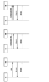
図1は、移動通信システムでULデータを送受信する第1方法を説明するフローチャートである。 FIG. 1 is a flowchart illustrating a first method for transmitting and receiving UL data in a mobile communication system.
図1に示された方法はLTE又は5G移動通信システムで端末と基地局間のULULデータ送受信手続きを示す。 The method shown in FIG. 1 shows a ULUL data transmission/reception procedure between a terminal and a base station in an LTE or 5G mobile communication system.
先ず、端末UEで基地局NBに送信すべきULデータが発生したと仮定する。例えば、前記ULデータは900byteであれば良い。 First, it is assumed that the terminal UE has generated UL data to be transmitted to the base station NB. For example, the UL data should be 900 bytes.
S100段階で、端末UEは自分に割り当てられたSR(scheduling request、スケジューリング要求)機会に基地局NBへSR(Scheduling_Request、スケジューリング要求、以下、SRと略す)を送信できる。 In step S100, the terminal UE can transmit an SR (Scheduling_Request, hereinafter abbreviated as SR) to the base station NB at an SR (scheduling request) opportunity assigned to the terminal UE.
S110段階で、前記基地局NBは前記端末UEが送信したSRを受信し、前記SRに応答して前記端末UEへULグラント(uplink grant(許可))を送信することによって前記端末UEに対してULリソースを割り当てできる。 In step S110, the base station NB receives the SR transmitted by the terminal UE and can allocate UL resources to the terminal UE by transmitting a UL grant (uplink grant) to the terminal UE in response to the SR.
この時、前記基地局NBは前記端末UEに何バイト(byte)のULデータが発生したのか分からない。
従って、前記基地局NBは前記端末UEに所定の(given)大きさに該当するULリソースを割り当てできる。例えば、前記基地局NBは前記端末UEにBSR(バッファ状況報告)を送信できるほどのULリソースを割り当てできる。
At this time, the base station NB does not know how many bytes of UL data are generated in the terminal UE.
Therefore, the base station NB can allocate UL resources corresponding to a given size to the terminal UE. For example, the base station NB can allocate enough UL resources to transmit a BSR (buffer status report) to the terminal UE.
図1では前記基地局NBが300byteのULデータを送信できるULリソースを前記端末UEに割り当てたと仮定する。 In FIG. 1, it is assumed that the base station NB has allocated a UL resource capable of transmitting 300 bytes of UL data to the terminal UE.
S120段階で、前記端末は前記基地局からULグラント(uplink grant)を受信して割り当てられたULリソースを介してULULデータを前記基地局へ送信できる。 In step S120, the terminal may receive a UL grant (uplink grant) from the base station and transmit UL UL data to the base station through the allocated UL resource.
図1では端末UEに900byteのULデータが発生したが、基地局NBは前記端末UEに300byteのULデータを送信できるリソースを割り当てたので、前記端末UEは発生したULデータ全部(即ち、900byte)を送信できない。 In FIG. 1, 900 bytes of UL data is generated at the terminal UE, but the base station NB has allocated resources for transmitting 300 bytes of UL data to the terminal UE, so the terminal UE cannot transmit all of the generated UL data (that is, 900 bytes).
S120段階で、端末UEは基地局NBにBSR(バッファ状態報告)を送信して自分が送信すべきULデータが600byte存在するという事実を前記基地局で通知できる。 In step S120, the terminal UE may transmit a BSR (buffer status report) to the base station NB to inform the base station that there are 600 bytes of UL data to be transmitted.
S130段階で、基地局NBは、端末UEからBSRを受信してBSRに含まれた情報、即ち、端末UEが送信すべきULデータが600byte存在するという事実に基づいて追加的に端末UEにリソースを割り当てできる。 In step S130, the base station NB receives the BSR from the terminal UE and additionally allocates resources to the terminal UE based on the fact that there are 600 bytes of UL data to be transmitted by the terminal UE, which is information included in the BSR.
S140段階で、端末UEは基地局NBからULグラントを受信した後に割り当てられたリソースを介して残余のULデータ(即ち、600byte)を前記基地局NBへ送信できる。 In step S140, the terminal UE can transmit remaining UL data (ie, 600 bytes) to the base station NB through the allocated resources after receiving the UL grant from the base station NB.
図2は、移動通信システムでULデータを送受信する第2方法を説明するフローチャートである。 FIG. 2 is a flowchart illustrating a second method for transmitting and receiving UL data in a mobile communication system.
図2に示された方法はLTE又は5G移動通信システムにおける端末と基地局間のULデータ送受信手続きを示す。 The method shown in FIG. 2 shows a UL data transmission/reception procedure between a terminal and a base station in an LTE or 5G mobile communication system.
先ず、端末で基地局に送信すべきULデータが発生したと仮定する。例えば、前記ULデータは900byteであるとする。 First, it is assumed that the terminal generates UL data to be transmitted to the base station. For example, assume that the UL data is 900 bytes.
S200段階で、端末は自分に割り当てられたSR機会で基地局にSRを送信できる。 In step S200, the terminal can send an SR to the base station at the SR opportunity assigned to it.
S210段階で、前記基地局は前記端末が送信したSRを受信し、前記SRに応答して前記端末へULグラントを送信することによって前記端末にULリソースを割り当てできる。 In step S210, the base station receives the SR transmitted by the terminal and can allocate UL resources to the terminal by transmitting a UL grant to the terminal in response to the SR.
この時、前記基地局は前記端末に何バイトのULデータが発生したのか分かる。従って、前記基地局は前記ULデータに相応する正確な大きさのULリソースを前記端末に割り当てできる。例えば、前記基地局は前記端末に900byteのULリソースを割り当てできる。 At this time, the base station knows how many bytes of UL data are generated in the terminal. Therefore, the base station can allocate UL resources of the correct size corresponding to the UL data to the terminal. For example, the base station can allocate UL resources of 900 bytes to the terminal.
S220段階で、前記端末は前記基地局からULグラントを受信して割り当てられたULリソースを介してULデータを前記基地局へ送信できる。 In step S220, the terminal may receive the UL grant from the base station and transmit UL data to the base station through the allocated UL resource.
図2では端末に900byteのULデータが発生することを認知した基地局が前記端末に900byteのULデータを送信できるリソースを割り当てる。 In FIG. 2, the base station, which recognizes that 900 bytes of UL data will be generated in the terminal, allocates a resource capable of transmitting 900 bytes of UL data to the terminal.
従って、図1に示された方法と比べて図2に示された方法はULデータ送受信手続きに要する時間を低減する効果がある。 Therefore, compared to the method shown in FIG. 1, the method shown in FIG. 2 has the effect of reducing the time required for the UL data transmission/reception procedure.

前記表1を参照すれば、第1方法は図1に示された方法による遅延(delay)又はレイテンシ(latency)を示し、第2方法は図2に示された方法による遅延又はレイテンシを示す。 Referring to Table 1, the first method indicates the delay or latency according to the method shown in FIG. 1, and the second method indicates the delay or latency according to the method shown in FIG.
ここで、端末が自分に割り当てられたSR機会を待つ時間を除いて、プロセッシング(processing)時間は3サブフレーム(TTI(送信時間間隔)と同一)と仮定した。 Here, it is assumed that the processing time is 3 subframes (the same as the TTI (Transmission Time Interval)) except for the time the terminal waits for its assigned SR opportunity.
図1に示された第1方法では、基地局は、端末が送信しようとするULデータの大きさが分からないので2回にわたってULグラントを行うので、総計17サブフレームの所要時間が発生することが分かる。 In the first method shown in FIG. 1, since the base station does not know the size of the UL data that the terminal intends to transmit, the UL grant is performed twice, so a total of 17 subframes is required.
即ち、第1方法の動作によれば基地局は端末に何バイトのULデータが発生したのかBSRを受信する迄分からない。従って、第1のULグラントを介して割り当てられたリソースでUL送受信を完了できなくなる。さらに、BSRを送受信する動作及び第2のULグラント及びデータ送受信動作で遅延が発生することを分かる。 That is, according to the operation of the first method, the base station does not know how many bytes of UL data have been generated in the terminal until it receives the BSR. Therefore, UL transmission/reception cannot be completed with the resources allocated via the first UL grant. Furthermore, it can be seen that delays occur in the operation of transmitting and receiving the BSR and the operation of transmitting and receiving the second UL grant and data.
図2に示された第2方法では、基地局は端末が送信しようとするULデータの大きさが分かっているので一回のULグラントを行うことによって、総計9サブフレームの所要時間が発生することが分かる。 In the second method shown in FIG. 2, since the base station knows the size of the UL data that the terminal intends to transmit, it can be seen that a total of 9 subframes are required by performing one UL grant.
即ち、基地局は、端末に発生したULデータの大きさが分かっているならば、端末からSRを受信した後に第1ULグラントを介して、端末が全てのULデータを一回に送信するように十分な量のリソースを割り当てできる。従って、端末と基地局間にBSR手続きが行われる前にUL送受信が完了される。 That is, if the base station knows the size of the UL data generated by the terminal, it can allocate a sufficient amount of resources for the terminal to transmit all UL data at once via the first UL grant after receiving the SR from the terminal. Therefore, UL transmission/reception is completed before the BSR procedure is performed between the terminal and the base station.
本発明ではUL送受信の遅延を減らすための方法を提案する。特に、5G移動通信システムでは低レイテンシ(low_latency)サービスをサポートするのが重要な性能指標中の一つである。このためにフィジカルレイヤー(physical layer)ではshort TTI及びNOMA(Non-Orthogonal Multiple Access)技術が研究されている。これらは送信の観点からレイテンシを減らすための核心的な技術であるが、端末に発生したULデータの大きさまでは考慮していない。 The present invention proposes a method for reducing the delay of UL transmission and reception. In particular, in a 5G mobile communication system, one of the important performance indicators is to support low latency (low_latency) services. For this reason, short TTI and NOMA (Non-Orthogonal Multiple Access) technologies are being studied in the physical layer. Although these are core techniques for reducing latency from the perspective of transmission, they do not consider the size of UL data generated in a terminal.
さらに、端末のサービス側面では、端末が初期の送信を速く行うことより、現在端末が送信しなければならない低レイテンシサービス関連ULデータ全部を一度に迅速に送信するのがより重要である。 Furthermore, in the service aspect of the terminal, it is more important for the terminal to quickly transmit all low-latency service-related UL data that the terminal currently has to transmit at once, rather than for the terminal to perform initial transmissions quickly.
このような観点から、本発明では基地局が端末からBSRを受信しなくても端末に発生したULデータの大きさを大略的に把握するようにする。 From this point of view, the present invention allows the base station to roughly grasp the size of UL data generated in the terminal without receiving the BSR from the terminal.
これは端末がSR送信後の第1のUL送信で自分に発生した全てのULデータを基地局に送信できる可能性を提供することによって全体的なUL送受信遅延を減らす効果がある。 This has the effect of reducing the overall UL transmission/reception delay by providing the possibility for the terminal to transmit all its generated UL data to the base station in the first UL transmission after the SR transmission.
基地局が端末からBSRを受信しなくても端末に発生したULデータの大きさの把握を可能にすることにより、本発明ではSR送受信動作を改善する方法を提案する。 The present invention proposes a method for improving the SR transmission/reception operation by enabling the base station to grasp the size of UL data generated in the terminal without receiving the BSR from the terminal.
本発明で提案する方法は次の通りである。 The method proposed by the present invention is as follows.
本発明の第1実施形態は、基地局が端末からBSRを受信しなくてもSR送信時点に基づいて端末に発生したULデータの大きさの把握を可能にする方法に関する。 A first embodiment of the present invention relates to a method for enabling a base station to grasp the size of UL data generated in a terminal based on the SR transmission time without receiving a BSR from the terminal.
本発明の第2-1実施形態は、基地局が端末からBSRを受信しなくてもSR送信回数に基づいて端末に発生したULデータの大きさの把握を可能にする方法に関する。 Embodiment 2-1 of the present invention relates to a method for enabling a base station to grasp the size of UL data generated in a terminal based on the number of SR transmissions without receiving a BSR from the terminal.
本発明の第2-2実施形態は、基地局が端末からBSRを受信しなくてもSR送信回数の解釈方法に基づいて端末に発生したULデータの大きさの把握を可能にする方法に関する。 Embodiment 2-2 of the present invention relates to a method for recognizing the size of UL data generated in a terminal based on the method of interpreting the number of SR transmissions even if the base station does not receive the BSR from the terminal.
本発明の第3実施形態は、基地局が端末からBSRを受信しなくても「Multiple_SR_bit」(以下、「多重SRビット」ともいう)に基づいて端末に発生したULデータの大きさの把握を可能にする方法に関するものである。 The third embodiment of the present invention relates to a method for enabling a base station to grasp the size of UL data generated in a terminal based on 'Multiple_SR_bit' (hereinafter also referred to as 'multiple SR bit') without receiving a BSR from the terminal.
本発明では次を仮定する。これは説明の便宜のためであって、他の仮定も同様な原理に基づいて適用できる。 The present invention assumes the following. This is for convenience of explanation and other assumptions can be applied based on similar principles.
1. 各端末はサブフレーム(subframe)ごとにSR機会を有する。これは低レイテンシサービスを用いる端末に対する妥当な仮定と見られる。 1. Each terminal has an SR opportunity every subframe. This seems a reasonable assumption for terminals using low-latency services.
2. 各端末はULデータが発生した時点において、ULに同期した(synchronized)状態なのでSR送信前に別途のRACH(Random_Access_Channel)手続きを行う必要がない。 2. Since each terminal is synchronized with the UL when the UL data is generated, there is no need to perform a separate RACH (Random_Access_Channel) procedure before transmitting the SR.
[第1実施形態] [First embodiment]
図3乃至図6は本発明の第1実施形態を説明するための図面である。前記第1実施形態は、端末のSR送信時点とバッファ状態(buffer status、以下、BSと略す)との間の関係を設定して端末は自分のバッファ状態BSに従ってSR送信時点を調節する方法に関する。 3 to 6 are drawings for explaining the first embodiment of the present invention. The first embodiment relates to a method of setting a relationship between an SR transmission time point and a buffer status (BS) of a terminal so that the terminal adjusts the SR transmission time point according to its own buffer status BS.
ここで「バッファ状態」(buffer status、BS)という用語は端末に発生したULデータの大きさ又は端末が送信すべきULデータの大きさを意味する。これはLTE標準で用いられる用語である。 Here, the term 'buffer status' (BS) means the size of UL data generated by the terminal or the size of UL data to be transmitted by the terminal. This is the terminology used in the LTE standard.
端末及び基地局は現在サブフレームインデクス(subframe index)に対応する予備的バッファ状態インデクス(preliminary buffer status index、以下 P-BSIと言う)を定義する。ここで、P-BSIは以下の数1のようにモジュロ(modulo)演算を介してM段階で表現できる。
The UE and the BS define a preliminary buffer status index (P-BSI) corresponding to the current subframe index. Here, the P-BSI can be expressed in M stages through a modulo operation as shown in
![]()
![]()
例えば、P-BSIは図3及び図4のように4段階(M=4)で表現できる。 For example, P-BSI can be expressed in four stages (M=4) as shown in FIGS.
端末及び基地局はRRC(Radio_Resourse_Control) signalingなどを介して各段階(m)のP-BSIに該当するバッファ状態BSを設定する。 The terminal and the base station set the buffer status BS corresponding to the P-BSI of each stage (m) through RRC (Radio_Resource_Control) signaling.
図3は、本発明の第1実施形態によるULデータ送受信方法を説明する図面である。 FIG. 3 is a diagram illustrating a UL data transmission/reception method according to a first embodiment of the present invention.
図3を参照すれば、10個のサブフレームが構成されて10個のサブフレームインデクス(0~9)が設定され、予め定義された4個のP-BSIが設定され得る。この時、P-BSIとULデータの関係は例えばマッピング関係により予め設定されている。 Referring to FIG. 3, 10 subframes are configured, 10 subframe indexes (0 to 9) are set, and 4 predefined P-BSIs can be set. At this time, the relationship between the P-BSI and UL data is preset by, for example, a mapping relationship.
図4は、本発明の第1実施形態によってバッファ状態(BS)インデクスとULデータのマッピング関係の例示を示す。 FIG. 4 shows an example of mapping relationship between Buffer Status (BS) index and UL data according to the first embodiment of the present invention.
図4を参照すれば、m=0であれば端末のバッファ(buffer)に0~300バイト(bytes)のULデータが存在し、m=1であれば端末のバッファに300~600バイトのULデータが存在し、m=2であれば端末のバッファに600~900バイトのULデータが存在し、m=3であれば端末のバッファに900~1200バイトのULデータが存在することを意味する。 Referring to FIG. 4, if m = 0, UL data of 0 to 300 bytes exists in the buffer of the terminal, if m = 1, UL data of 300 to 600 bytes exists in the buffer of the terminal, if m = 2, UL data of 600 to 900 bytes exists in the buffer of the terminal, and if m = 3, it means that UL data of 900 to 1200 bytes exists in the buffer of the terminal.
図3及び図4を参照すれば、第3サブフレーム(m=2)でULデータ(例えば、700バイト)が発生すれば、第3サブフレーム(m=2)は第3P-BSI(k=2)にマッピングされるので、端末は第3サブフレーム(m=2)で直ちにSR(スケジューリング要求)を送信できる。 3 and 4, if UL data (eg, 700 bytes) occurs in the third subframe (m = 2), the third subframe (m = 2) is mapped to the third P-BSI (k = 2), so the terminal can immediately transmit an SR (scheduling request) in the third subframe (m = 2).
さらに、第9サブフレーム(m=8)でULデータ(例えば、1000バイト)が発生すれば、第9サブフレーム(m=8)は第1P-BSI(k=0)にマッピングされるので、端末は第9サブフレーム(m=8)でSRを送信しない。前記端末はULデータ(例えば、1000バイト)に相応する第4P-BSI(k=3)を認知し、第4P-BSI(k=3)に相応する第2サブフレーム(m=1)でSRを送信できる。 Furthermore, if UL data (e.g., 1000 bytes) occurs in the 9th subframe (m = 8), the 9th subframe (m = 8) is mapped to the 1st P-BSI (k = 0), so the terminal does not transmit SR in the 9th subframe (m = 8). The terminal can recognize the 4th P-BSI (k=3) corresponding to UL data (eg, 1000 bytes) and transmit SR in the 2nd subframe (m=1) corresponding to the 4th P-BSI (k=3).
さらに、第7サブフレーム(m=6)でULデータ(例えば、100バイト)が発生すれば、第7サブフレーム(m=6)は第4P-BSI(k=3)にマッピングされるので、端末は、第7サブフレーム(m=6)でSRを送信しない。前記端末はULデータ(例えば、100バイト)に相応する第1P-BSI(k=0)を認知し、第1P-BSI(k=0)に相応する第8サブフレーム(m=7)でSRを送信できる。 Furthermore, if UL data (e.g., 100 bytes) occurs in the 7th subframe (m = 6), the 7th subframe (m = 6) is mapped to the 4th P-BSI (k = 3), so the terminal does not transmit SR in the 7th subframe (m = 6). The terminal can recognize the first P-BSI (k=0) corresponding to UL data (eg, 100 bytes) and transmit SR in the eighth subframe (m=7) corresponding to the first P-BSI (k=0).
図5は、本発明の第1実施形態による基地局と端末間のULリソース割り当てを説明するフローチャートである。 FIG. 5 is a flowchart illustrating UL resource allocation between a base station and terminals according to the first embodiment of the present invention.
第1実施形態によって端末及び基地局が各段階のP-BSIに該当するバッファ状態BSを設定できる。 According to the first embodiment, the terminal and the base station can set the buffer status BS corresponding to each stage of P-BSI.
S500段階で、端末は自身が低レイテンシサービスをサポートするというprofile情報を基地局に通知できる。又は、端末は基地局にP-BSIの設定をリクエストできる。 In step S500, the terminal can notify the base station of profile information indicating that the terminal supports the low-latency service. Alternatively, the terminal can request the base station to configure the P-BSI.
S510段階で、基地局は端末にバッファ状態レベル(即ち、P-BSIレベル、M値)を通知できる。ここで、RRCメッセージ内のMAC-MainConfig IEなどが使用できる。 In step S510, the base station can inform the terminal of the buffer status level (ie, P-BSI level, M value). Here, the MAC-MainConfig IE, etc. in the RRC message can be used.
S520段階で、端末は基地局に好むバッファ状態レベル(即ち、P-BSIレベル、M値)を通知できる。ここで、新たに定義されたnew IEなどが使用できる。 In step S520, the terminal can notify the base station of its preferred buffer status level (ie, P-BSI level, M value). Here, a newly defined new IE, etc. can be used.
S530段階で、端末はSRのように各段階のP-BSIに該当するBSR(バッファ状態情報)を決定して基地局に報告する。 In step S530, the terminal determines BSR (buffer status information) corresponding to the P-BSI of each step like SR and reports it to the base station.
ここで、各段階のP-BSIに該当するバッファ状態情報BSRは次によって表現できる。 Here, the buffer status information BSR corresponding to each stage of P-BSI can be expressed as follows.
1. バッファ状態BSのlower bound及びupper bound 1. lower bound and upper bound of buffer state BS
(例示) m=1:Xlower_bound<バッファ状態BS<Xupper_bound (Example) m=1: Xlower_bound<buffer state BS<Xupper_bound
2. バッファ状態BSの中間値及び範囲 2. Intermediate value and range of buffer status BS
(例示) m=2:median=Xmedian及びrange=R →
Xmedian-R/2<バッファ状態BS<Xmedian+R/2
(Example) m = 2: median = X median and range = R →
Xmedian-R/2<buffer state BS<Xmedian+R/2
従って、端末は基地局に各段階のP-BSIに該当するバッファ状態BSのlower bound及びupper bound又は中間値及び範囲などを決定して報告できる。 Therefore, the terminal can determine and report the lower bound and upper bound or the intermediate value and range of the buffer status BS corresponding to the P-BSI of each stage to the base station.
他の方法として端末は各段階のP-BSIに該当するバッファ状態情報BSRとして既存の LTE MAC標準(TS36.321)に定義されているBSR向けバッファサイズ(table6.1.3.1-1)及びBSR向け拡張バッファサイズ(table6.1.3.1-2)にあるインデクスを基地局に報告できる。 As another method, the terminal is defined in the existing LTE MAC standard (TS36.321) as the buffer status information BSR corresponding to the P-BSI of each stage, the buffer size for BSR (table6.1.3.1-1) and the index in the extended buffer size for BSR (table6.1.3.1-2) can be reported to the base station.
S540段階で、基地局は端末が送信したバッファ状態情報BSRに相応するULグラントを端末で送信できる。基地局は自分とP-BSIを設定した端末からSRを受信すればSRを受信したサブフレームのP-BSIを識別して端末のバッファ状態BSを把握する。そして、端末のバッファ状態BSを考慮してUL schedulingを行う。 In step S540, the base station can transmit to the terminal a UL grant corresponding to the buffer status information BSR transmitted by the terminal. When the base station receives an SR from a terminal that has set up a P-BSI with itself, the base station identifies the P-BSI of the subframe in which the SR is received and grasps the buffer status BS of the terminal. Then, UL scheduling is performed in consideration of the buffer state BS of the terminal.
基地局のUL schedulingは具現事項だが本発明が效果を得るためには、基地局のschedulerが端末に対して全てのULデータを第1のULグラントを介して送信できるほどのリソースを割り当てられることが好ましい。 UL scheduling of the base station is a matter of implementation, but in order for the present invention to be effective, it is preferable that the scheduler of the base station is allocated enough resources to transmit all UL data to the terminal via the first UL grant.
図6は、本発明の第1実施形態による端末の動作を示すフローチャートである。 FIG. 6 is a flow chart showing the operation of the terminal according to the first embodiment of the present invention.
S600段階で、端末が基地局に送信すべきULデータが発生する。S610段階で、前記端末は自分のバッファ状態BSを識別する。 In step S600, UL data to be transmitted from the terminal to the base station is generated. At step S610, the terminal identifies its buffer status BS.
S620段階で、前記端末は識別されたバッファ状態BSがどんなP-BSIに対応されるか識別し、識別されたP-BSIに対応するサブフレームを選択できる。 In step S620, the terminal can identify which P-BSI the identified buffer status BS corresponds to and select a subframe corresponding to the identified P-BSI.
S630段階で、前記端末は現在時点から識別されたサブフレームまで待機して当該サブフレームでSRを送信できる。 In step S630, the terminal can wait until the identified subframe from the current time and transmit the SR in that subframe.
本発明の第1実施形態に必要となる時間が総9~12サブフレームが所要されることを分かる。
P-BSIを4段階で設定した例ではSR送信遅延が最大4サブフレームまで発生ができるからである。前記表1を参照すれば、第1実施形態で所要される9~12サブフレームは第1方法で所要された17サブフレーム対比約30~47%減少した値に該当する。
It can be seen that a total of 9 to 12 subframes are required for the first embodiment of the present invention.
This is because an SR transmission delay of up to four subframes can occur in an example in which P-BSI is set in four stages. Referring to Table 1, 9 to 12 subframes required in the first embodiment correspond to 30 to 47% less than 17 subframes required in the first method.
第1実施形態では各P-BSIに該当するバッファ状態BSが全てlower limit及びupper limitが存在する例示に対して説明した。しかし、端末に発生するトラフィック(traffic)の大きさはランダム(random)であるのでここに対応するP-BSIが存在しないこともある。例えば、端末に発生したtrafficの大きさが2000バイトの場合にはここに対応するP-BSIが存在しない。このような場合、端末は下記のように動作するようにする。 In the first embodiment, all the buffer status BSs corresponding to each P-BSI have the lower limit and the upper limit. However, since the amount of traffic generated in the terminal is random, there may be no corresponding P-BSI. For example, when the size of traffic generated in a terminal is 2000 bytes, there is no corresponding P-BSI. In such a case, the terminal should operate as follows.
-各SRリソースに割り当てられたP-BSIと関係なくtraffic発生時点から最も早いSRリソースでSRを送信する。 - Transmit SR using the earliest SR resource from when traffic occurs regardless of the P-BSI allocated to each SR resource.
-端末に発生したtrafficの大きさと正確に一致しないがこれと最も類似なP-BSIに該当するSRリソースで SRを送信する。 - Transmit SR on the SR resource corresponding to the P-BSI that is most similar to, but does not exactly match, the amount of traffic generated by the terminal.
提案方案で端末は既存方案と同様にSR送信後に受信したULグラントを介して基地局にデータ及びBSRを送信するようになる。この時、基地局は端末からBSRを受信することによって端末のバッファ状態BSを把握できる。 In the proposed scheme, the terminal transmits data and BSR to the base station through the received UL grant after transmitting the SR, as in the existing scheme. At this time, the base station can grasp the buffer status BS of the terminal by receiving the BSR from the terminal.
従って、端末に発生するtrafficの大きさに対応するP-BSIが存在しなくても提案方案は問題なく動作できる。 Therefore, even if there is no P-BSI corresponding to the amount of traffic generated in the terminal, the proposed scheme can operate without problems.
[第2-1実施形態] [2-1 embodiment]
図7乃至図9は、本発明の第2-1実施形態を説明するための図面である。前記第2-1実施形態は端末の連続されたSR送信回数とバッファ状態BSとの間の関係を設定して端末は自分のバッファ状態BSによって連続されたSR送信回数を調節する方法に関するものである。 7 to 9 are drawings for explaining the 2-1 embodiment of the present invention. The 2-1 embodiment relates to a method for setting the relationship between the number of consecutive SR transmissions of the terminal and the buffer status BS, and allowing the terminal to adjust the number of consecutive SR transmissions according to its own buffer status BS.
図7は、本発明の第2-1実施形態によるULデータ送受信方法を説明する図面である。 FIG. 7 is a diagram for explaining the UL data transmission/reception method according to the 2-1 embodiment of the present invention.
端末及び基地局はRRC signalingなどを介して連続されたSR送信回数(N)に対応するP-BSIを設定する。ここで、P-BSIは第1実施形態でのP-BSIと同一の意味を有する。即ち、端末が送信すべきULデータの大きさがどの範囲に属するかに対する情報を示す。 The terminal and the base station configure P-BSI corresponding to the number of consecutive SR transmissions (N) through RRC signaling. Here, P-BSI has the same meaning as P-BSI in the first embodiment. That is, it indicates information about the size range of UL data to be transmitted by the terminal.
図8は、本発明の第2-1実施形態によってSR送信回数とULデータ大きさのマッピング関係の例示を示す。 FIG. 8 shows an example of the mapping relationship between the number of SR transmissions and the UL data size according to the 2-1 embodiment of the present invention.
図8を参照すれば、当該例示で連続されたSR送信回数が1(N=1)であれば端末のバッファに0~300バイトのULデータが存在することを意味し、連続されたSR送信回数が2(N=2)であれば端末のバッファに300~600バイトのULデータが存在することを意味し、連続されたSR送信回数が3(N=3)であれば端末のバッファに600~900バイトのULデータが存在することを意味する。 Referring to FIG. 8, if the number of consecutive SR transmissions is 1 (N=1), it means that UL data of 0 to 300 bytes exists in the terminal buffer, if the number of consecutive SR transmissions is 2 (N=2), it means that UL data of 300 to 600 bytes exists in the buffer of the terminal, and if the number of consecutive SR transmissions is 3 (N=3), it means that UL data of 600 to 900 bytes exists in the buffer of the terminal. do.
図7乃至図8を参照すれば、端末が基地局でSRを1回送信することで前記端末は0~300バイトのULデータが存在することを前記基地局に通知できる。また、端末が基地局でSRを2回送信することによって前記端末は300~600バイトのULデータが存在することを前記基地局に通知できる。また、端末が基地局でSRを3回送信することによって前記端末は600~900バイトのULデータが存在することを前記基地局に通知できる。 Referring to FIGS. 7 and 8, the terminal can notify the base station of the presence of UL data of 0 to 300 bytes by transmitting the SR once to the base station. In addition, the terminal can notify the base station that 300 to 600 bytes of UL data exist by transmitting the SR twice at the base station. In addition, the terminal can inform the base station that there is UL data of 600 to 900 bytes by transmitting the SR three times to the base station.
基地局は端末のSR送信回数に基づいて前記端末が送信しようとするULデータの大きさを把握し、前記ULデータの大きさに相応するULグラントを前記端末で送信できる。前記端末は前記ULグラントに応答して前記ULデータを前記基地局へ送信できる。 The base station can determine the size of UL data that the terminal intends to transmit based on the number of SR transmissions of the terminal, and transmit a UL grant corresponding to the size of the UL data from the terminal. The terminal can transmit the UL data to the base station in response to the UL grant.
端末及び基地局が連続されたSR送信回数に対応するP-BSIを設定する動作は第1実施形態と類似に図5の手続きを介して成る。先ず、基地局は端末に最大連続SR送信回数に対する情報を提供する。 The operation of setting the P-BSI corresponding to the number of consecutive SR transmissions by the terminal and the base station is performed through the procedure of FIG. 5, similar to the first embodiment. First, the base station provides the terminal with information on the maximum number of consecutive SR transmissions.
もし、端末が基地局に送信すべきULデータが発生すれば次のように動作する。 If the terminal has UL data to be transmitted to the base station, it operates as follows.
端末は自分のバッファ状態BSを識別し、識別されたバッファ状態BSがどんなP-BSIに対応されるか識別する。前記端末は識別されたP-BSIに対応する連続されたSR送信回数を識別する。前記端末は現在サブフレームから識別された連続されたSR送信回数ほどSRを送信する。 The terminal identifies its buffer state BS and identifies to what P-BSI the identified buffer state BS corresponds. The terminal identifies the number of consecutive SR transmissions corresponding to the identified P-BSI. The terminal transmits SRs for the number of consecutive SR transmissions identified from the current subframe.
基地局は自分とP-BSIを設定した端末からSRを受信すれば何回連続SRが受信されたか識別して端末のバッファ状態BSを把握する。そして、端末のバッファ状態BSを考慮してUL schedulingを行う。 If the base station receives SRs from the terminals that have set up the P-BSI with itself, the base station recognizes how many consecutive SRs have been received and grasps the buffer status BS of the terminals. Then, UL scheduling is performed in consideration of the buffer state BS of the terminal.
基地局のUL schedulingは具現事項であるが本発明が効果を得るためには基地局のschedulerが、端末の全てのULデータを第1のULグラントを介して送信できるほどのリソースを端末に対して割り当てられることが好ましい。 Although the UL scheduling of the base station is a matter of implementation, in order for the present invention to be effective, the scheduler of the base station preferably allocates enough resources to the terminal to transmit all UL data of the terminal through the first UL grant.
図9は、本発明の第2-1実施形態によってSR送信を禁止するタイマーを設定する過程を示す。 FIG. 9 shows a process of setting a timer for prohibiting SR transmission according to the 2-1 embodiment of the present invention.
LTEに基づく第2-1実施形態を具現するためには標準で端末の連続されたSR送信が許容されなければならない。現在LTE標準では端末が1回SRを送信すればsr-ProhibitTimerが作動して当該timerが満了する前までさらにSRを送信できないように定義されている。 In order to implement the 2-1 embodiment based on LTE, the standard should allow continuous SR transmission of the terminal. Currently, the LTE standard defines that if a terminal transmits an SR once, an sr-ProhibitTimer is activated and no more SRs can be transmitted until the timer expires.
従って、第2-1実施形態では端末の連続されたSR送信が許容されるようにsr-ProhibitTimerの作動開始時点が図9のように変更されなければならない。 Therefore, in the 2-1 embodiment, the operation start point of the sr-ProhibitTimer should be changed as shown in FIG. 9 so as to allow continuous SR transmission of the terminal.
-sr-ProhibitTimer作動開始時点=初SR送信時点から最大連続SR送信回数ほど遅延された時点 - sr-ProhibitTimer activation start time = time delayed by the maximum number of consecutive SR transmissions from the time of first SR transmission
-図7及び図8では最大連続SR送信回数が3と設定されているから図9のようにサブフレーム2で初SR送信が成る場合、3サブフレームが遅延された時点であるサブフレーム5からsr-ProhibitTimerが作動し始める。
- Since the maximum number of consecutive SR transmissions is set to 3 in FIGS. 7 and 8, when the first SR transmission occurs in
[第2-2実施形態] [2-2 Embodiment]
図10乃至図11は、本発明の第2-2実施形態を説明するための図面である。 10 and 11 are drawings for explaining the second-second embodiment of the present invention.
前記第2-2実施形態は端末の一定区間内SR送信をビットマップ(bitmap)で形成した後、当該ビットマップとバッファ状態BSとの間の関係を設定して活用する方法である。端末は自分のバッファ状態BSによってSR送信を制御する。 The 2-2 embodiment is a method of forming the SR transmission within a certain period of the terminal as a bitmap, and then setting and utilizing the relationship between the bitmap and the buffer status BS. A terminal controls SR transmission by its buffer status BS.
図10は、本発明の第2-2実施形態によるULデータ送受信方法を説明する図面である。 FIG. 10 is a diagram for explaining the UL data transmission/reception method according to the 2-2 embodiment of the present invention.
図10を参照すれば、一定区間内のSR送信をビットマップで形成する構成が開示されている。もし、端末に2サブフレーム間のSR送信が許容されると、SR送信の有無によって00、01、10、11のビットマップが表現可能である。例えば、第1のサブフレームでSRが送信されて第2のサブフレームでSRが送信されなければ、前記ビットマップは“10”と表現できる。 Referring to FIG. 10, there is disclosed a configuration for forming SR transmission within a certain interval as a bitmap. If the terminal is allowed to transmit SR for two subframes, bitmaps of 00, 01, 10, and 11 can be expressed depending on whether or not SR transmission is performed. For example, if SR is transmitted in the first subframe and SR is not transmitted in the second subframe, the bitmap can be expressed as '10'.
さらに、もし、端末が3サブフレーム間のSR送信が許容されると、同様に000、001、010、011、100、101、110、111のビットマップが表現可能である。例えば、第1のサブフレームでSRが送信されて第2のサブフレームでSRが送信されず第3のサブフレームでSRが送信されると、前記ビットマップは“101”と表現できる。 In addition, if the terminal is allowed to transmit SR for three subframes, bitmaps of 000, 001, 010, 011, 100, 101, 110, and 111 can be expressed as well. For example, if SR is transmitted in the first subframe, SR is not transmitted in the second subframe, and SR is transmitted in the third subframe, the bitmap can be expressed as '101'.
端末及び基地局はRRC signalingなどを介して一定区間内のSR送信基盤ビットマップに対応するP-BSIを設定する。ここで、P-BSIは第1実施形態でのP-BSIと同一の意味を有する。即ち、端末が送信すべきULデータの大きさがどの範囲に属するかに対する情報を示す。 The terminal and the base station configure P-BSI corresponding to the SR transmission-based bitmap within a certain interval through RRC signaling. Here, P-BSI has the same meaning as P-BSI in the first embodiment. That is, it indicates information about the size range of UL data to be transmitted by the terminal.
図11は、本発明の第2-2実施形態によってSR送信に係るビットマップULデータのマッピング関係の例示を示す。図11を参照すれば、ビットマップに端末のバッファ状態BSを対応できる。 FIG. 11 shows an example of mapping relationship of bitmap UL data for SR transmission according to the 2-2 embodiment of the present invention. Referring to FIG. 11, the bitmap can correspond to the buffer status BS of the terminal.
図11を参照すれば、3サブフレーム内のSR送信基盤ビットマップが100(SR送信on → off → off)であれば端末のバッファに1200~1500バイトのULデータが存在することを意味する。 Referring to FIG. 11, if the SR transmission based bitmap in 3 subframes is 100 (SR transmission on→off→off), it means that 1200 to 1500 bytes of UL data exist in the buffer of the terminal.
端末及び基地局が一定区間内のSR送信基盤ビットマップに対応するP-BSIを設定する動作は第1実施形態と類似に図5の手続きを介して成る。基地局は端末にSR送信が行なわれる一定区間に対する情報を提供する。 The operation of the terminal and the base station setting the P-BSI corresponding to the SR transmission-based bitmap within a certain interval is performed through the procedure of FIG. 5, similar to the first embodiment. The base station provides the terminal with information on a certain interval in which SR transmission is performed.
もし、端末が基地局に送信すべきULデータが発生すれば次のように動作する。 If the terminal has UL data to be transmitted to the base station, it operates as follows.
端末は自分のバッファ状態BSを識別し、識別されたバッファ状態BSがどんなP-BSIに対応されるか識別する。前記端末は識別されたP-BSIに対応する一定区間内のSR送信基盤ビットマップを識別する。前記端末は現在サブフレームから一定区間の間の識別されたビットマップのようにSRを送信する。 The terminal identifies its buffer state BS and identifies to what P-BSI the identified buffer state BS corresponds. The terminal identifies an SR transmission basis bitmap within a certain interval corresponding to the identified P-BSI. The terminal transmits SR as a bitmap identified for a certain period from the current subframe.
もし、端末のバッファ状態BSが1200~1500バイト間の場合、端末はこれから3サブフレーム間のSR送信をon →off→off形態で行う。 If the buffer status BS of the terminal is between 1200 and 1500 bytes, the terminal performs SR transmission for the next three subframes in the form of on→off→off.
基地局は自分とP-BSIを設定した端末からSRを受信すると、一定区間の間のどんなビットマップ形態でSRが受信されたか識別して端末のバッファ状態BSを把握する。 When the base station receives the SR from the terminal that has set up the P-BSI with itself, the base station identifies the bitmap form in which the SR was received during a certain period, and grasps the buffer status BS of the terminal.
そして、端末のバッファ状態BSを考慮してUL schedulingを行う。 Then, UL scheduling is performed in consideration of the buffer state BS of the terminal.
基地局のUL schedulingは具現事項であるが本発明が効果を得るためには、基地局のschedulerが、端末の全てのULデータを第1のULグラントを介して送信できるほどのリソースを端末に対して割り当てられることが好ましい。 Although the UL scheduling of the base station is a matter of implementation, in order for the present invention to be effective, it is preferable that the scheduler of the base station allocate enough resources to the terminal to transmit all UL data of the terminal via the first UL grant.
[第3実施形態] [Third embodiment]
図12乃至図13は、本発明の第3実施形態を説明するための図面である。前記第3実施形態は多重ビットから構成されたSR信号を用いてUL送受信手続きを行う方法に関する。 12 and 13 are drawings for explaining the third embodiment of the present invention. The third embodiment relates to a method of performing a UL transmission/reception procedure using an SR signal composed of multiple bits.
図12は、本発明の第3実施形態によるULデータ送受信方法を説明する図面である。図12を参照すれば、PUCCHフォーマット4でバッファ状態情報BSRを示すSRを多重ビットで設定できる。
FIG. 12 is a diagram illustrating a UL data transmission/reception method according to a third embodiment of the present invention. Referring to FIG. 12, in
現在LTEはSR信号としてon-off keying based signalingを用いる。これと異なり本発明ではSR信号として多重ビットから構成されたSR信号を提案する。これは端末のSRビットとバッファ状態BSとの間の関係を設定して端末は自分のバッファ状態BSによって特定SRビットを送信する方法である。このために多様なcode、sequenceなどを活用できる。本発明はここに活用されるSRビット、code、sequenceなどに限定されない。 Currently, LTE uses on-off keying based signaling as the SR signal. Unlike this, the present invention proposes an SR signal composed of multiple bits as the SR signal. This is a method of setting the relationship between the SR bit of the terminal and the buffer status BS, and the terminal transmits a specific SR bit according to its own buffer status BS. For this purpose, various codes, sequences, etc. can be used. The present invention is not limited to the SR bits, codes, sequences, etc. utilized herein.
端末及び基地局はRRC signalingなどを介してSRビットに対応するP-BSIを設定する。ここで、P-BSIは第1実施形態でのP-BSIと同一意味を有する。即ち、端末が送信すべきULデータの大きさがどの範囲に属するかに対する情報を示す。 The terminal and the base station configure the P-BSI corresponding to the SR bit through RRC signaling. Here, P-BSI has the same meaning as P-BSI in the first embodiment. That is, it indicates information about the size range of UL data to be transmitted by the terminal.
図13(A)は、本発明の第3-1実施形態によって多重ビットから構成されたSRとULデータのマッピング関係の例示を示す図面である。 FIG. 13A is a drawing showing an example of mapping relationship between SR and UL data composed of multiple bits according to the 3-1 embodiment of the present invention.
図13(A)を参照すれば、当該例示でSRビットが“0100”であれば端末のバッファに2000~2500バイトのULデータが存在することを意味する。 Referring to FIG. 13A, if the SR bit is "0100" in this example, it means that 2000 to 2500 bytes of UL data exist in the buffer of the terminal.
端末及び基地局がSRビットに対応するP-BSIを設定する動作は第1実施形態と類似に図5の手続きを介してなる。基地局は端末にSR信号が何のビットから構成されているかに対する情報を提供する。 The operation of setting the P-BSI corresponding to the SR bit by the terminal and the base station is performed through the procedure of FIG. 5, similar to the first embodiment. The base station provides the terminal with information about what bits the SR signal consists of.
もし、端末が基地局に送信すべきULデータが発生すれば次のように動作する。端末は自分のバッファ状態BSを識別し、識別されたバッファ状態BSがどんなP-BSIに対応されるか識別する。前記端末は識別されたP-BSIに対応するSRビットを識別し、識別されたSRビットから構成されたSR信号を送信する。 If the terminal has UL data to be transmitted to the base station, it operates as follows. The terminal identifies its buffer state BS and identifies to what P-BSI the identified buffer state BS corresponds. The terminal identifies SR bits corresponding to the identified P-BSI and transmits an SR signal composed of the identified SR bits.
端末が送信すべきULデータが2000~2500バイト範囲内に存在すれば端末はSRビット0100から構成されたSR信号を送信する。
If the UL data to be transmitted by the terminal exists within the range of 2000 to 2500 bytes, the terminal transmits an SR signal composed of
本発明で端末が多重ビットから構成されたSR信号を送信する時、BPSK、QPSK、QAM など多様なmodulation方法を適用できる。本発明はこれを送信する時、適用されるmodulation 及びcoding方法によって限定されない。 In the present invention, various modulation methods such as BPSK, QPSK, and QAM can be applied when a terminal transmits an SR signal composed of multiple bits. The present invention is not limited by the modulation and coding method applied when transmitting it.
基地局はSR信号を受信してSRビットを識別して端末のバッファ状態BSを把握する。 The base station receives the SR signal, identifies the SR bit, and grasps the buffer status BS of the terminal.
そして、端末のバッファ状態BSを考慮してUL schedulingを行う。 Then, UL scheduling is performed in consideration of the buffer state BS of the terminal.
<追加1>
<
本発明ではSR信号が多重ビットから構成されている時、当該ビットの組合せを端末のバッファ状態BSに対応させる方案を提案した。従って、基地局がSR信号を受信した時端末のUL送信必要可否だけではなくバッファ状態情報BSRまで把握するようにして基地局が端末に適合した大きさのULリソースを迅速に割り当てできるようにした。これと同様な原理で本発明ではSR信号を構成する多重ビットの組合せをバッファ状態BSだけでなく多様な情報に対応できるようにする。これは次の例を含む。 In the present invention, when the SR signal is composed of multiple bits, a scheme is proposed in which the combination of the corresponding bits corresponds to the buffer status BS of the terminal. Therefore, when the base station receives the SR signal, the base station knows not only whether the terminal needs to transmit UL but also the buffer status information BSR, so that the base station can quickly allocate UL resources suitable for the terminal. Based on the same principle, the present invention allows the combination of multiple bits forming the SR signal to correspond to various information as well as the buffer status BS. This includes the following examples:
I.SR信号を構成する多数ビットの組合せは端末が送信しようとするtrafficの種類に対応できる。 I. A combination of multiple bits forming the SR signal can correspond to the type of traffic that the terminal intends to transmit.
a.ここでtraffic種類とは、voice、video、text message、FTP、HTTPなどになり得る。 a. Here, the traffic type can be voice, video, text message, FTP, HTTP, and the like.
b.基地局が特定traffic種類に対応するSR信号を端末から受信すれば基地局は端末が当該trafficを送信するのに適合した時間/周波数/空間/numerology/TTIリソースを端末に割り当てる。 b. When a base station receives an SR signal corresponding to a specific traffic type from a terminal, the base station allocates time/frequency/space/numerology/TTI resources suitable for the terminal to transmit the traffic to the terminal.
II.SR信号を構成する多重ビットの組合せは端末が送信しようとするUL dataを生成したサービス又はapplicationの種類に対応できる。 II. A combination of multiple bits forming the SR signal can correspond to the type of service or application that generated the UL data that the terminal intends to transmit.
a.ここでサービス又はapplication種類とは、例えば、SNS(Social Networking Service)、V2V(Vehicle-to-Vehicle)、V2I(Vehicle-to-Infra structure)、V2P (Vehicle-to-Person)、ニュースなどになり得る。 a. Here, the service or application type can be, for example, SNS (Social Networking Service), V2V (Vehicle-to-Vehicle), V2I (Vehicle-to-Infrastructure), V2P (Vehicle-to-Person), news, and the like.
b.基地局が特定サービス又はapplication種類に対応するSR信号を端末から受信すれば基地局は端末が当該サービス又はapplicationから発生したdataを送信するのに適合した時間/周波数/空間/numerology/TTIリソースを端末に割り当てる。 b. When a base station receives an SR signal corresponding to a specific service or application type from a terminal, the base station allocates time/frequency/space/numerology/TTI resources suitable for the terminal to transmit data generated from the service or application to the terminal.
III.SR信号を構成する多重ビットの組合せは端末が送信しようとするUL dataが属した Logical channelに対応できる。 III. A combination of multiple bits forming an SR signal can correspond to a logical channel to which UL data to be transmitted by a terminal belongs.
a.基地局が特定Logical channelに対応するSR信号を端末から受信すれば基地局は端末が当該logical channelで発生したdataを送信するのに適合した時間/周波数/空間/numerology/TTIリソースを端末に割り当てる。 a. When a base station receives an SR signal corresponding to a specific logical channel from a terminal, the base station allocates time/frequency/space/numerology/TTI resources suitable for the terminal to transmit data generated in the corresponding logical channel to the terminal.
IV.SR信号を構成する多重ビットの組合せは端末が送信しようとするUL dataが属したlogical channel groupに対応できる。 IV. A combination of multiple bits forming an SR signal can correspond to a logical channel group to which UL data to be transmitted by the terminal belongs.
a.基地局が特定logical channel groupに対応するSR信号を端末から受信すれば基地局は端末が当該logical channel groupで発生したdataを送信するのに適合した時間/周波数/空間/numerology/TTIリソースを端末に割り当てる。 a. When a base station receives an SR signal corresponding to a specific logical channel group from a terminal, the base station allocates time/frequency/space/numerology/TTI resources suitable for the terminal to transmit data generated in the corresponding logical channel group to the terminal.
V.SR信号を構成する多重ビットの組合せは端末が送信しようとするUL dataが属したnetwork sliceに対応できる。ここでnetwork sliceとは、例えば、eMBB(enhanced Mobile BroadBand) slice、URLLC(Ultra Reliable&Low Latency(低レイテンシ) Communication)slice、mMTC (massive Machine Type Communication)slice などになり得る。 V. A combination of multiple bits forming an SR signal can correspond to a network slice to which UL data to be transmitted by a terminal belongs. Here, the network slice includes, for example, eMBB (enhanced Mobile BroadBand) slice, URLLC (Ultra Reliable & Low Latency Communication) slice, mMTC (massive Machine Type Communication) slice. on) slice and so on.
a.基地局が特定network sliceに対応するSR信号を端末から受信すれば基地局は端末が当該network sliceで発生したdataを送信するのに適合した時間/周波数/空間/numerology/TTIリソースを端末に割り当てる。 a. When a base station receives an SR signal corresponding to a specific network slice from a terminal, the base station allocates time/frequency/space/numerology/TTI resources suitable for the terminal to transmit data generated in the corresponding network slice to the terminal.
VI.SR信号を構成する多重ビットの組合せは端末が送信しようとするUL dataの送受信に適合したnumerologyに対応できる。 VI. A combination of multiple bits forming an SR signal can correspond to a numerology suitable for transmission/reception of UL data to be transmitted by a terminal.
a.ここで、numerologyとはsubcarrier spacingなどを意味するのに(15*2)mkHz、即ち、15kHz(m=0)、30kHz(m=1)、60kHz(m=2)、120kHz(m=3)などになり得、15*nkHz、即ち、15kHz(n=1)、30kHz(n=2)、45kHz(n=3)、60kHz(n=4)など多様な方法に表現される値のうちの一部となり得る。 a. Here, numerology means subcarrier spacing, etc., and can be (15*2)mkHz, i.e., 15kHz (m=0), 30kHz (m=1), 60kHz (m=2), 120kHz (m=3), etc.; n=3), 60 kHz (n=4), etc., can be some of the values expressed in various ways.
b.基地局が特定numerologyに対応するSR信号を端末から受信すれば基地局は当該numerologyに対応する時間/周波数/空間リソースを端末に割り当てる。 b. When a base station receives an SR signal corresponding to a specific numerology from a terminal, the base station allocates time/frequency/spatial resources corresponding to the corresponding numerology to the terminal.
VII.SR信号を構成する多重ビットの組合せは端末が送信しようとするUL dataの送受信に適合したTTI長さに対応できる。 VII. A combination of multiple bits forming an SR signal can correspond to a TTI length suitable for transmission/reception of UL data to be transmitted by a terminal.
a.ここで、TTI長さとはサブフレーム長さ、slot長さ、mini-slot長さ、PDCCHのような制御チャンネルの送信周期などを意味するのに例えば 1/2mms、即ち、1ms(m=0)、0.5ms(m=1)、0.25ms(m=2)、0.125ms(m=3)など多様な方法に表現される値のうちの一部となり得る。 a. Here, the TTI length means subframe length, slot length, mini-slot length, transmission period of a control channel such as PDCCH, etc., and can be a part of values expressed in various ways such as 1/2mms, that is, 1ms (m=0), 0.5ms (m=1), 0.25ms (m=2), 0.125ms (m=3).
b.基地局が特定TTI長さに対応するSR信号を端末から受信すれば基地局は当該TTI長さに対応する時間/周波数/空間リソースを端末に割り当てる。 b. When the base station receives an SR signal corresponding to a specific TTI length from the terminal, the base station allocates time/frequency/spatial resources corresponding to the TTI length to the terminal.
VIII.SR信号を構成する多重ビットの組合せは端末が送信しようとするUL dataのレイテンシ(latency)要求事項に対応できる。 VIII. A combination of multiple bits forming the SR signal can meet latency requirements of UL data that the terminal intends to transmit.
a.ここで、レイテンシ要求事項は時間単位(s又はms)又はサブフレーム単位などで表現できる。これは(i)端末がSR信号を送信する時点から基地局からULリソースを割り当てられる時点の間の最大許容時間又は(ii)端末がSR信号を送信する時点から端末がUL dataを送信する時点の間の最大許容時間などを意味し得る。 a. Here, the latency requirement can be expressed in units of time (s or ms) or subframes. This may mean (i) the maximum allowable time between when the terminal transmits the SR signal and the time when the UL resource is allocated from the base station or (ii) the maximum allowable time between when the terminal transmits the SR signal and when the terminal transmits UL data.
b.基地局が特定のレイテンシ要求事項に対応するSR信号を端末から受信すれば基地局は端末がUL data送信時のレイテンシ要求事項を満足するのに適合した時間/周波数/空間/numerology/TTIリソースを端末に割り当てる。 b. If the base station receives an SR signal corresponding to a specific latency requirement from the terminal, the base station allocates time/frequency/space/numerology/TTI resources suitable for the terminal to satisfy the latency requirement when transmitting UL data to the terminal.
IX.SR信号を構成する多重ビットの組合せは端末が送信しようとするUL dataのQCI(QoS Class Identifier)に対応できる。 IX. A combination of multiple bits forming an SR signal can correspond to QoS Class Identifier (QCI) of UL data to be transmitted by the terminal.
a.ここで、QCIは以下の表6のようにLTEに定義されているQCIを包含できる。 a. Here, QCI may include QCI defined in LTE as shown in Table 6 below.

b.基地局が特定QCIに対応するSR信号を端末から受信すれば基地局は端末が当該QCIを満足するのに適合した時間/周波数/空間/numerology/TTIリソースを端末に割り当てる。 b. When the base station receives an SR signal corresponding to a specific QCI from the terminal, the base station allocates time/frequency/space/numerology/TTI resources suitable for the terminal to satisfy the corresponding QCI to the terminal.
X.SR信号を構成する多重ビットの組合せは今まで説明した多様な要素(即ち、端末のバッファ状態BS、UL traffic種類、service又はapplication 種類、logical channel、logical channel group、network slice、numerology、TTI 長さ、レイテンシ要求事項、QoS class identifier)の組合せに対応できる。 X. The combination of multiple bits forming the SR signal includes various elements described above (namely, terminal buffer status BS, UL traffic type, service or application type, logical channel, logical channel group, network slice, numerology, TTI length, latency requirements, QoS class ident ifier) combination.
<追加2>
<
本発明ではSR信号が多重ビットから構成されている時に当該ビットの組合せを端末のバッファ状態BSに対応させる方法を提案した。また<追加1>でSR信号を構成する多重ビットの組合せが多様な情報に対応できるようにした。 このような拡張を本発明で提案した全ての方法に適用しようとする。
The present invention proposes a method of making the combination of bits correspond to the buffer status BS of the terminal when the SR signal is composed of multiple bits. In <
本発明では多重ビットから構成されたSR信号を用いる方法外にも(a)SR信号を互いに異なる時間又は周波数又はcodeリソースを介して送信する方法及び(b)SR信号を連続的に送信する方法を提案した。
従って、本発明では互いに異なるSR時間又は周波数又はcodeリソース各々が端末のバッファ状態BS、UL traffic 種類、service又はapplication種類、logical channel、logical channel group、network slice、numerology、TTI 長さ、レイテンシ要求事項、QoS class identifier又はこれらの組合せなどに対応できる。
In addition to the method using the SR signal composed of multiple bits, the present invention proposes (a) a method of transmitting the SR signal through different times or frequencies or code resources, and (b) a method of continuously transmitting the SR signal.
Therefore, in the present invention, each different SR time or frequency or code resource is a terminal buffer status BS, UL traffic type, service or application type, logical channel, logical channel group, network slice, numerology, TTI length, latency requirements, QoS class identifier er or a combination thereof.
さらに、SR信号の連続送信回数が端末のバッファ状態BS、UL traffic種類、service又はapplication種類、logical channel、logical channel group、network slice、numerology、TTI長さ、レイテンシ要求事項、QoS class identifier又はこれらの組合せなどに対応できる。このような対応関係が図13(C)に表現されている。 Furthermore, the number of continuous transmission of the SR signal is the buffer status BS, UL TRAFFIC type, Service or Application type, Logical Cannnel, Logical Cannnel Group, Network Slic, Network Slic. E, NUMEROLOGY, TTI length, latency requirements, QOS Class Identifier or these combinations can be used. Such correspondence is expressed in FIG. 13(C).
基地局のULスケジューリングは、システムの具現化状況に依存する事項だが、本発明が効果を得るためには、基地局のスケジューラが、端末の全てのULデータを最初のULグラントを介して送信できるほどのリソースを端末に対して割り当てられることが好ましい。 UL scheduling of the base station is a matter of system implementation, but for the present invention to be effective, the scheduler of the base station preferably allocates enough resources to the terminal to transmit all the UL data of the terminal via the first UL grant.
今まで本発明を説明する時、毎サブフレームごとに端末に割り当てられたSRリソースがあることを仮定した。しかし、本発明はサブフレームごとに端末に割り当てられたSRリソースが存在しなくてもSRリソースごとにP-BSIを割り当てることによって適用できる。 So far, when describing the present invention, it is assumed that there are SR resources allocated to the terminal every subframe. However, the present invention can be applied by allocating P-BSI for each SR resource even if there is no SR resource allocated to the terminal for each subframe.
図13(B)は、本発明の第3-2実施形態によってコード基盤SRとULデータのマッピング関係の例示を示す。 FIG. 13B shows an example of the mapping relationship between code-based SR and UL data according to the 3-2 embodiment of the present invention.
図13(B)を参照すれば、code基盤SRを活用して自分のバッファ状態BSに従って特定codeを送信できる。例えば、Code2がSRで用いられる端末のバッファに500~1000バイトのULデータが存在することを意味する。 Referring to FIG. 13B, a specific code can be transmitted according to its own buffer status BS using the code-based SR. For example, it means that UL data of 500 to 1000 bytes exists in the buffer of the terminal whose Code2 is used in SR.
端末及び基地局はRRC signalingなどを介してcode基盤SRに対応するP-BSIを設定する。ここで、P-BSIは第1実施形態でのP-BSIと同一の意味を有する。即ち、端末が送信すべきULデータの大きさがどの範囲に属するかに対する情報を示す。 A terminal and a base station configure P-BSI corresponding to code-based SR through RRC signaling. Here, P-BSI has the same meaning as P-BSI in the first embodiment. That is, it indicates information about the size range of UL data to be transmitted by the terminal.
端末及び基地局が各codeに対応するP-BSIを設定する動作は実施形態1と同様に以下の手続きを介してなる。 The operation of setting the P-BSI corresponding to each code by the terminal and the base station is performed through the following procedures as in the first embodiment.
基地局は端末にSR-based BS level数を決定して各BS levelに対応するcodeを割り当てる。端末は各BSlevelに対応するバッファ状態BSの範囲を基地局に通知する。 The base station determines the number of SR-based BS levels for the terminal and assigns a code corresponding to each BS level. The terminal informs the base station of the buffer status BS range corresponding to each BSLevel.
もし、端末が基地局に送信すべきULデータが発生すれば次のように動作する。端末は自分のバッファ状態BSを識別し、識別されたバッファ状態BSがどんなP-BSIに対応されるか識別する。前記端末は識別されたP-BSIに対応するSR用codeを識別し、識別されたcodeから構成されたSR信号を送信する。 If the terminal has UL data to be transmitted to the base station, it operates as follows. The terminal identifies its buffer state BS and identifies to what P-BSI the identified buffer state BS corresponds. The terminal identifies an SR code corresponding to the identified P-BSI and transmits an SR signal composed of the identified code.
基地局はSR用codeを受信してこれを識別して端末のバッファ状態BSを把握する。そして、端末のバッファ状態BSを考慮してUL schedulingを行う。 The base station receives the code for SR, identifies it, and grasps the buffer state BS of the terminal. Then, UL scheduling is performed in consideration of the buffer state BS of the terminal.
基地局のUL schedulingは具現事項だが本発明が効果を得るためには、基地局のschedulerが、端末の全てのULデータを第1のULグラントを介して送信できるほどのリソースを端末に対して割り当てられることが好ましい。 Although the UL scheduling of the base station is a matter of implementation, in order for the present invention to be effective, it is preferable that the scheduler of the base station allocate enough resources to the terminal to transmit all the UL data of the terminal via the first UL grant.
図14乃至図20は、本発明の実施形態によってSRリソースにバッファ状態(BS)インデクスを設定する過程を説明する図面である。 14 to 20 are diagrams illustrating a process of setting a buffer status (BS) index in an SR resource according to an embodiment of the present invention.
図14は、本発明の実施形態によってSRリソースにBSインデクスを設定する過程を示す。この時、前記BSインデクスは前述したP-BSIを意味する。 FIG. 14 shows a process of setting a BS index on SR resources according to an embodiment of the present invention. At this time, the BS index means the P-BSI described above.
図14では端末に2サブフレームごとにSRリソースが割り当てられた状態を示す。サブフレーム内で割り当てられるSRリソース(1401~1411)各々に順次にP-BSIを割り当てできる。 FIG. 14 shows a state in which SR resources are allocated to terminals every two subframes. A P-BSI can be assigned to each of the SR resources (1401-1411) assigned within a subframe in sequence.
図15は、本発明の他の実施形態によってSRリソースにBSインデクスを設定する過程を示す図面である。 FIG. 15 illustrates a process of setting a BS index in SR resources according to another embodiment of the present invention.
図15ではnormal TTIとshort TTIが一つのサブフレームに共存して1normal TTIごとにSRリソース(1501~1505)が割り当てられ、2short TTI ごとにSRリソース(1507~1517)が割り当てられた状態を示す。もし、総P-BSI levelの数が6の場合には一つのサブフレーム内でshort TTIのSRリソース(例えば、1507、1509)にP-BSIが優先的に割り当てられ、normal TTIのSRリソース(例えば、1501)にP-BSIを後で割り当てできる。 FIG. 15 shows a state in which normal TTI and short TTI coexist in one subframe, SR resources (1501 to 1505) are allocated for each normal TTI, and SR resources (1507 to 1517) are allocated for every two short TTIs. If the total number of P-BSI levels is 6, P-BSI can be preferentially allocated to SR resources of short TTI (eg, 1507, 1509) within one subframe, and P-BSI can be allocated later to SR resource of normal TTI (eg, 1501).
図16は、本発明のまた他の実施形態によってSRリソースにBSインデクスを設定する過程を示す。 FIG. 16 shows a process of setting a BS index on SR resources according to another embodiment of the present invention.
図16ではnormal TTIとshort TTIが一つのサブフレームに共存して1normal TTIごとにSRリソース(1601~1605)が割り当てられ、2short TTIごとにSRリソース(1604~1617)が割り当てられた状態を示す。総P-BSI levelの数が6の場合には一つのサブフレーム内でnormal TTIのSRリソース(例えば、1601)にP-BSIが優先的に割り当てられ、short TTIのSRリソース(例えば、1607、1609)に P-BSIを後で割り当てできる。 FIG. 16 shows a state in which normal TTI and short TTI coexist in one subframe, SR resources (1601 to 1605) are allocated for each normal TTI, and SR resources (1604 to 1617) are allocated for every two short TTIs. When the total number of P-BSI levels is 6, P-BSI is preferentially allocated to SR resources (eg, 1601) of normal TTI within one subframe, and P-BSI can be allocated later to SR resources (eg, 1607, 1609) of short TTIs.
図17は、本発明のまた他の実施形態によってSRリソースにBSインデクスを設定する過程を示す。 FIG. 17 shows a process of setting a BS index on SR resources according to another embodiment of the present invention.
図17は、normal TTIとshort TTIが一つのサブフレームに共存して1normal TTIごとにSRリソース(1701~1705)が割り当てられ、2short TTIごとにSRリソース(1707~1717)が割り当てられた状態を示す。 FIG. 17 shows a state in which normal TTI and short TTI coexist in one subframe, SR resources (1701-1705) are allocated for each normal TTI, and SR resources (1707-1717) are allocated for every two short TTIs.
もし、総P-BSIlevelの数が6の場合には一つのサブフレーム内で時間的に先ず存在するSRリソースのうちでshort TTIのSRリソース(例えば、1707)にP-BSIが優先的に割り当てられてnormal TTIのSRリソース(例えば、1701)にP-BSIを後で割り当てできる。 If the total number of P-BSI levels is 6, the P-BSI can be preferentially allocated to the SR resource (eg, 1707) of the short TTI among the SR resources temporally existing in one subframe, and the P-BSI can be allocated later to the SR resource (eg, 1701) of the normal TTI.
図18は、本発明のまた他の実施形態によってSRリソースにBSインデクスを設定する過程を示す図面である。 FIG. 18 is a diagram illustrating a process of setting a BS index to SR resources according to another embodiment of the present invention.
図18はnormal TTIとshort TTIが一つのサブフレームに共存して1normal TTIごとにSRリソース(1801~1805)が割り当てられ、2short TTIごとにSRリソース(1807~1817)が割り当てられた状態を示す。 FIG. 18 shows a state in which normal TTI and short TTI coexist in one subframe, SR resources (1801-1805) are allocated for each normal TTI, and SR resources (1807-1817) are allocated for every two short TTIs.
もし、総P-BSI levelの数が6の場合には時間的に先ず存在するSRリソース(例えば、1807、1809)にP-BSIが優先的に割り当てられて時間的に後で存在するSRリソースに P-BSI(例えば、1801)を後で割り当てできる。 If the total number of P-BSI levels is 6, P-BSIs are preferentially allocated to SR resources (eg, 1807, 1809) that exist temporally first, and P-BSIs (eg, 1801) can be allocated later to SR resources that exist temporally later.
図19は、本発明のまた他の実施形態によってSRリソースにBSインデクスを設定する過程を示す図面である。 FIG. 19 illustrates a process of setting a BS index to SR resources according to another embodiment of the present invention.
図19ではnormal TTIとshort TTIが一つのサブフレームに共存して1normal TTIごとにSRリソース(1901~1905)が割り当てられ、2short TTIごとにSRリソース(1907~1917)が割り当てられた状態を示す。もし、総P-BSI levelの数が4の場合にはshort TTIに存在するSRリソース(例えば、1907、1909)には P-BSIが割り当てられてnormal TTIに存在するSRリソース(例えば、1901)には P-BSIが割り当てられないこともある。 FIG. 19 shows a state in which normal TTI and short TTI coexist in one subframe, SR resources (1901 to 1905) are allocated for each normal TTI, and SR resources (1907 to 1917) are allocated for every two short TTIs. If the total number of P-BSI levels is 4, P-BSI may be allocated to SR resources (eg, 1907, 1909) existing in short TTIs and no P-BSI may be allocated to SR resources (eg, 1901) existing in normal TTIs.
図20は、本発明のまた他の実施形態によってSRリソースにBSインデクスを設定する過程を示す図面である。 FIG. 20 illustrates a process of setting a BS index to SR resources according to another embodiment of the present invention.
図20ではnormal TTIとshort TTIが一つのサブフレームに共存して1normal TTIごとにSRリソース(2001~2005)が割り当てられ、2short TTIごとにSRリソース(2007~2017)が割り当てられた状態を示す。 FIG. 20 shows a state in which normal TTI and short TTI coexist in one subframe, SR resources (2001 to 2005) are allocated for each normal TTI, and SR resources (2007 to 2017) are allocated for every two short TTIs.
もし、総P-BSI levelの数が4の場合には前記の図のようにnormal TTIに存在するSRリソース(例えば、2001)にはP-BSIが割り当てられてshort TTIに存在するSRリソース(例えば、2007、2009)にはP-BSIが割り当てられないこともある。 If the total number of P-BSI levels is 4, P-BSI may be allocated to SR resources (eg, 2001) existing in normal TTI as shown in the above figure, and P-BSI may not be allocated to SR resources (eg, 2007, 2009) existing in short TTI.
図14乃至図20ではnormal TTIとshort TTIが共存する時、P-BSIがどんな規則によって割り当てられるかに対する多様な例示を説明した。 FIGS. 14 to 20 have described various examples of how the P-BSI is assigned when the normal TTI and the short TTI coexist.
これを要約すれば次の通りである。 This can be summarized as follows.
<一つのTTI種類だけ用いられる場合> <When only one TTI type is used>
割り当てられたSRリソース順にP-BSIを割り当てる。 Assign P-BSIs in the order of assigned SR resources.
<Normal TTIとshort TTIが共に用いられる場合> <When both normal TTI and short TTI are used>
規則1:一つのサブフレーム(又は一つのnormal TTI)内で先ずshort TTIに割り当てられたSRリソース順にP-BSIを割り当てて、その後にnormal TTIに割り当てられたSRリソース順にP-BSIを割り当てる。 Rule 1: Within one subframe (or one normal TTI), P-BSIs are first allocated in the order of SR resources allocated to the short TTI, and then P-BSIs are allocated in the order of SR resources allocated to the normal TTI.
規則2:一つのサブフレーム(又は一つのnormal TTI)内で先ずnormal TTIに割り当てられたSRリソース順にP-BSIを割り当てて、その後にshort TTIに割り当てられたSRリソース順にP-BSIを割り当てる。 Rule 2: Within one subframe (or one normal TTI), first assign P-BSIs in the order of SR resources assigned to the normal TTI, and then assign P-BSIs in the order of SR resources assigned to the short TTI.
規則3:一つのサブフレーム(又は一つのnormal TTI)内で時間的に先ず割り当てられたSRリソース順にP-BSIを割り当てるがshort TTIのSRリソースとnormal TTIのSRリソースが同時に存在する場合、short TTIのSRリソースに先ずP-BSIを割り当てる。 Rule 3: In one subframe (or one normal TTI), P-BSI is allocated in the order of SR resources allocated first in terms of time, but if SR resources of short TTI and SR resources of normal TTI exist at the same time, P-BSI is allocated first to SR resources of short TTI.
規則4:一つのサブフレーム(又は一つのnormal TTI)内で時間的に先ず割り当てられたSRリソース順にP-BSIを割り当てるがshort TTIのSRリソースとnormal TTIのSRリソースが同時に存在する場合、normal TTIのSRリソースに先ずP-BSIを割り当てる。 Rule 4: P-BSI is allocated in the order of SR resources allocated first in time within one subframe (or one normal TTI), but if SR resources of short TTI and SR resources of normal TTI exist at the same time, P-BSI is first allocated to SR resources of normal TTI.
規則5:Short TTIに割り当てられたSRリソースにだけその順にP-BSIを割り当てる。 Rule 5: Assign P-BSI only to SR resources assigned to Short TTI, in that order.
規則6:Normal TTIに割り当てられたSRリソースにだけその順にP-BSIを割り当てる。 Rule 6: Assign P-BSI only to SR resources assigned to Normal TTI, in that order.
本発明では基地局と端末が前記の規則を互いに共有するようにする。これはRRCsignaling(RRCConnectionReconfigurationメッセージなど)などを介して基地局が現在運営中のframe structure及び端末に割り当てられたSRリソースに従って規則インデクスを端末に伝達されるようにする。 The present invention allows the base station and the terminal to share the above rules with each other. This allows the base station to transmit the rule index to the terminal according to the frame structure currently being operated by the base station and the SR resources allocated to the terminal through RRC signaling (RRCConnectionReconfiguration message, etc.).
ここで、基地局と端末は各インデクスに該当する規則の内容を予め定められた規格などを介して事前に分かっている場合もある。 Here, the base station and the terminal may know the content of the rule corresponding to each index in advance through a predetermined standard.
[第4実施形態] [Fourth embodiment]
図21乃至図22は、本発明の第4実施形態を説明するための図面である。 21 and 22 are drawings for explaining the fourth embodiment of the present invention.
今まで本発明は時間領域でSR送信時点とP-BSI間の関係を設定して端末が自分のバッファ状態BSによってSR送信時点を調節するようにした。 So far, the present invention sets the relationship between the SR transmission time and the P-BSI in the time domain so that the terminal adjusts the SR transmission time according to its buffer status BS.
同様な原理を介して本発明は周波数領域で端末に割り当てられた多重SRリソースが存在する時に同一時点及び互いに異なる周波数に存在する各SRリソースとP-BSI間の関係を設定して端末が自分のバッファ状態BSに従ってSR送信リソースを選択するようにする。 Based on the same principle, the present invention sets the relationship between each SR resource existing at the same time and different frequency and P-BSI when there are multiple SR resources allocated to the terminal in the frequency domain, so that the terminal selects the SR transmission resource according to its buffer status BS.
図21は、本発明の第4-1実施形態によるULデータ送受信方法を説明する図面である。 FIG. 21 is a diagram for explaining the UL data transmission/reception method according to the 4-1 embodiment of the present invention.
図21を参照すれば、端末は一つのサブフレーム 私の同一時点及び互いに異なる周波数に4個のSRリソースを割り当てできる。各SRリソースは 0<BS(バッファ状態)<1000バイト、1000<BS<2000バイト、2000<BS<3000バイト、3000<BS<4000バイトの P-BSI各々に対応される。 Referring to FIG. 21, a terminal can allocate 4 SR resources at the same time and different frequencies in one subframe. Each SR resource corresponds to a P-BSI of 0<BS (buffer status)<1000 bytes, 1000<BS<2000 bytes, 2000<BS<3000 bytes, and 3000<BS<4000 bytes.
もし、端末に2500バイトのULデータが発生した場合、端末は4個のリソース(2101~2107)のうちで第3SRリソース2105を介してSRを送信する。基地局は端末から第3SRリソース2015を介してSRを受信すれば端末のバッファ状態BSを把握し、これを考慮してUL schedulingを行うことができる。
If UL data of 2500 bytes is generated in the terminal, the terminal transmits SR through the
ここで端末及び基地局は第1実施形態の図5のように各々のSRリソースに対応するP-BSIを設定する過程を行うことができる。この時、基地局は端末に周波数領域で総幾のSRリソースが割り当てられるかに対する情報を通知するようにする。 Here, the terminal and the base station can perform the process of setting P-BSI corresponding to each SR resource as shown in FIG. 5 of the first embodiment. At this time, the base station notifies the terminal of information on how many SR resources are allocated in the frequency domain.
図22は、本発明の第4-2実施形態によるULデータ送受信方法を説明する図面である。 FIG. 22 is a diagram for explaining the UL data transmission/reception method according to the 4-2 embodiment of the present invention.
同様な原理を介して本発明は時間及び周波数領域で端末に割り当てられた多重SRリソースが存在する時、互いに異なる時間及び周波数に存在する各SRリソースとP-BSI間の関係を設定して端末が自分のバッファ状態BSによってSR送信リソースを選択するようにできる。 Through a similar principle, when there are multiple SR resources allocated to a terminal in the time and frequency domain, the present invention sets the relationship between each SR resource existing in different time and frequency and P-BSI so that the terminal can select an SR transmission resource according to its buffer status BS.
図22を参照すれば、端末は一つのサブフレーム内の互いに異なる時間及び周波数に8個のSRリソースを割り当てられた。また、各SRリソース(2201~2215)は0<BS<500バイト、500<BS<1000バイト、1000<BS<1500バイト、1500<BS<2000バイト、2000<BS<2500バイト、2500<BS<3000バイト、3000<BS<3500バイト、3500<BS<4000バイトの P-BSIに対応される。 Referring to FIG. 22, a terminal is allocated 8 SR resources at different times and frequencies within one subframe. Each SR resource (2201 to 2215) is a P-BSI of 0<BS<500 bytes, 500<BS<1000 bytes, 1000<BS<1500 bytes, 1500<BS<2000 bytes, 2000<BS<2500 bytes, 2500<BS<3000 bytes, 3000<BS<3500 bytes, 3500<BS<4000 bytes. corresponds to
もし、端末が3300バイトのULデータが発生した場合、8個のSRリソース(2201~2215)のうちの第7SRリソース2213を介してSRを送信するようになる。基地局は端末から第7SRリソース2213を介してSRを受信すれば端末のバッファ状態BSを把握し、これを考慮してUL schedulingを行う。
If the terminal generates UL data of 3300 bytes, it will transmit SR through the
この時、端末及び基地局は第1実施形態の図5のように各々のSRリソースに対応するP-BSIを設定する過程を行うことができる。 At this time, the terminal and the base station can perform the process of setting P-BSI corresponding to each SR resource as shown in FIG. 5 of the first embodiment.
この時、基地局は端末に時間及び周波数領域で総幾のSRリソースが割り当てられるかに対する情報を通知するようにする。 At this time, the base station notifies the terminal of information on how many SR resources are allocated in the time and frequency domains.
[第5実施形態] [Fifth embodiment]
図23乃至図27は、本発明の第5実施形態を説明するための図面である。 23 to 27 are drawings for explaining the fifth embodiment of the present invention.
本発明で端末はSR送信後に基地局からULグラントを受信して自分に割り当てられたULリソースを介してBSR又はデータを送信する動作を考慮した。しかし、最近non-orthogonal multiple access(NOMA、power domain、code domain、その他のdomain NOMA全部含み) 技術が活発に研究されているので端末はSR送信なしに基地局にBSR又はデータを送信なし得る。 In the present invention, the terminal receives a UL grant from the base station after transmitting the SR and considers the operation of transmitting the BSR or data through the UL resource allocated to itself. However, since non-orthogonal multiple access (NOMA, power domain, code domain, and all other domain NOMAs) technology has been actively researched recently, the terminal can transmit BSR or data to the base station without transmitting SR.
図23は、本発明の第5-1実施形態によるUL送受信方法を説明する図面である。第5-1実施形態はNOMAを用いたSRを送信してULグラントを受信する方法に関する。 FIG. 23 is a diagram for explaining the UL transmission/reception method according to the 5-1 embodiment of the present invention. The 5-1 embodiment relates to a method of transmitting an SR using NOMA and receiving a UL grant.
図23を参照すれば、各端末にSRリソースをdedicatedするように割り当てるのではなく多重端末が(基地局によって事前にpairingされた端末group又は事前にpairingされない任意の端末)共通のリソースを介してSR信号を送信する動作を示す。各端末にSRリソースをdedicatedするように割り当てることはリソース活用側面でoverheadと見られる。従って、SRリソースをNOMA基盤で送信するようになればこのようなoverheadを減らすことができるという長所がある。 Referring to FIG. 23, instead of allocating dedicated SR resources to each terminal, multiple terminals (a terminal group pre-paired by the base station or any terminal not pre-paired) transmit an SR signal via a common resource. Dedicated allocation of SR resources to each terminal is considered an overhead in terms of resource utilization. Therefore, if the SR resource is transmitted based on NOMA, there is an advantage that such overhead can be reduced.
図24は、本発明の第5-2実施形態によるUL送受信方法を説明する図面である。第5-2実施形態はNOMAを用いたBSRを送信してULグラントを受信する方法に関する。 FIG. 24 is a diagram for explaining the UL transmission/reception method according to the 5-2 embodiment of the present invention. The 5-2 embodiment relates to a method of transmitting a BSR using NOMA and receiving a UL grant.
図25は、本発明の第5-3実施形態によるUL送受信方法を説明する図面である。第5-3実施形態はNOMAを用いて全てのデータを送信する方法に関する。 FIG. 25 is a diagram for explaining the UL transmission/reception method according to the 5-3 embodiment of the present invention. The fifth-third embodiment relates to a method of transmitting all data using NOMA.
このような動作のために先ず基地局は一つ以上の端末をpairingする動作を行う。Pairingされた端末は同一時間及び周波数リソースを介して信号を送信しても基地局がcode domain、power domain又はその他のdomainでSIC(Successive Interference Cancellation)を行ってpairingされた端末が送信した信号を互いに区分した後にdecodingできる。しかし、NOMA技術によって端末pairing 過程が必要ではない場合もあり得る。 For this operation, the base station first pairs one or more terminals. Even if paired terminals transmit signals through the same time and frequency resources, the base station performs SIC (Successive Interference Cancellation) in a code domain, power domain, or other domain, and the signals transmitted by the paired terminals can be separated from each other and then decoded. However, the NOMA technology may not require the terminal pairing process.
NOMA技術を用いると、SR及びULグラント手続きなしでもULデータを送信できる。もし、送信すべきULデータの大きさが第1のNOMA送信のために割り当てられたリソースで送信するのに相対的に大きければ端末は送信すべきULデータの一部とBSRを、NOMA送信を介して基地局に送信する。これを受信した基地局はBSRに含まれた端末のバッファ状態情報BSRを基盤で端末に十分な量のリソースを割り当てて端末が迅速にUL送信を完了するようにする。 With NOMA technology, UL data can be transmitted without SR and UL grant procedures. If the size of the UL data to be transmitted is relatively large to transmit on the resources allocated for the first NOMA transmission, the terminal transmits part of the UL data to be transmitted and the BSR to the base station via NOMA transmission. Upon receiving this, the base station allocates a sufficient amount of resources to the terminal based on the terminal's buffer status information BSR included in the BSR so that the terminal can quickly complete UL transmission.
図26は、本発明の実施形態によってSRリソースとNOMA基盤SRリソースが共存する状況を示す図面であり、図27は、本発明の他の実施形態によってSRリソースとNOMA基盤SRリソースが共存する状況を示す図面である。 FIG. 26 illustrates the coexistence of SR resources and NOMA-based SR resources according to an embodiment of the present invention, and FIG. 27 illustrates the coexistence of SR resources and NOMA-based SR resources according to another embodiment of the present invention.
この時、(a)特定端末に専用に割り当てられた既存のSRリソースと(b)NOMA基盤とするが1つ以上の端末に共通に割り当てられた新規SRリソースが サブフレーム別に(図26)又はサブフレーム内のshort/normal TTI別に(図27)共存する状況を示す。このために基地局は端末に(a)のようなSRリソースに対するconfiguration情報と(b)のようなSRリソースに対するconfiguration情報を通知する。ここで、configuration情報とはSRリソースが存在する時間(symbol、slot、TTI、サブフレーム、frameなど)、周波数(subcarrier、RE、RB、subbandなど)、周期及び種類 (a又はb)などであり得る。 At this time, (a) existing SR resources dedicated to a specific terminal and (b) new SR resources based on NOMA but commonly allocated to one or more terminals coexist for each subframe (FIG. 26) or for each short/normal TTI within a subframe (FIG. 27). To this end, the base station notifies the terminal of configuration information for SR resources such as (a) and configuration information for SR resources such as (b). Here, the configuration information may include time (symbol, slot, TTI, subframe, frame, etc.) in which SR resources exist, frequency (subcarrier, RE, RB, subband, etc.), period and type (a or b).
本発明では5G移動通信システムでのSR動作に対して説明している。5G移動通信システムでは一つのradio access network及びcore networkで多数のサービスがサポートされることで予想される。例えば、サービス1はeMBB(enhanced mobile broadband)、サービス2はURLLC (ultra-reliable and low-Latency(低レイテンシ) communications)、サービス3はeMTC (enhanced MTC)であり得る。この外にも他のサービスが追加にサポートされ得る。これら各々のサービスは互いに異なるphysical layer特性を有し得る(例えば、subcarrier spacing)。従って、基地局は端末にサービス別の独立的なSRリソースが割り当てでき、全てのサービスに共通的に使用できるSRリソースを割り当てできる。
The present invention describes an SR operation in a 5G mobile communication system. A 5G mobile communication system is expected to support multiple services in a single radio access network and core network. For example,
図28は、本発明の実施形態によってサービス別でSRリソースが用いられることを説明する図面である。図28を参照すれば、端末に割り当てられた全てのSRリソース(2801~2819)は全てのサービスに共通的に使用できる。 FIG. 28 is a diagram illustrating that SR resources are used for each service according to an embodiment of the present invention. Referring to FIG. 28, all SR resources (2801-2819) allocated to the terminal can be commonly used for all services.
図29は、本発明の他の実施形態によってサービス別でSRリソースが用いられることを説明する図面である。図29を参照すれば、端末に割り当てられた各々のSRリソース(2901~2919)を当該サービスに対応して使用できる。 FIG. 29 is a diagram illustrating that SR resources are used for each service according to another embodiment of the present invention. Referring to FIG. 29, each SR resource (2901-2919) allocated to the terminal can be used corresponding to the service.
図30は、本発明のまた他の実施形態によってサービス別でSRリソースが用いられることを説明する図面である。図30を参照すれば、互いに異なる種類のTTIに存在するSRリソースのうちの一部は全てのサービスに共通的に用いられるように設定されており、一部は各サービスに対応して用いられるように設定できる。 FIG. 30 is a diagram illustrating that SR resources are used for each service according to another embodiment of the present invention. Referring to FIG. 30, some of the SR resources existing in different types of TTIs can be set to be commonly used for all services, and some can be set to be used corresponding to each service.
図31は、本発明の実施形態によるSR送受信手続きを説明する図面である。 FIG. 31 is a diagram illustrating an SR transmission/reception procedure according to an embodiment of the present invention.
図31を参照すれば、S3100段階で端末はUEcapability情報交換時自分が使用する(又は使用できる)サービス情報を基地局に提供する。 Referring to FIG. 31, in step S3100, the terminal provides the base station with service information that it uses (or can use) when exchanging UE capability information.
S3110段階で、基地局は端末が用いるサービスを把握した後、common SR又はservice-specific SR configuration情報を端末に提供する。これは以下の表6に示す「SchedulingRequestConfig」(SR(スケジューリング要求)構成)のような形式を介して実行できる。
In step S3110, the base station provides common SR or service-specific SR configuration information to the terminal after identifying the service used by the terminal. This can be done via a form such as the "SchedulingRequestConfig" (SR (scheduling request) configuration) shown in Table 6 below.

もし、端末がN個の互いに異なるサービスを用いると、基地局は端末に各サービス別で1個又はその以上又はその以下のservice-specific SRリソースを割り当てできる。 If a terminal uses N different services, the base station can allocate one, more, or less service-specific SR resources to the terminal for each service.
また、0個又は1個又はその以上のcommon SRリソースを割り当てできる。 Also, 0 or 1 or more common SR resources can be allocated.
S3120段階で、端末は基地局からSR configuration情報を受信した後、特定サービスに該当するUL trafficが発生すれば自分に割り当てられたSRリソースのうちで一つを選択して基地局にSRを送信する。 In step S3120, after receiving the SR configuration information from the base station, the terminal selects one of the SR resources allocated to itself and transmits an SR to the base station if UL traffic corresponding to a specific service occurs.
<端末が1個のサービスを用いる場合> <When one terminal uses a service>
端末は当該サービスのために割り当てられたservice-specific SRリソースを介して基地局にSRを送信できる。 A terminal can send an SR to a base station through a service-specific SR resource allocated for the service.
また、端末はcommon SRリソースを介して基地局にSRを送信できる。 Also, the terminal can transmit the SR to the base station through common SR resources.
Common SRリソースの活用は、例えば、端末にT1サブフレーム後のservice-specific SRリソースが割り当てられているのにT1より短いT2サブフレーム後のcommon SRリソースが割り当てられていると、端末はservice-specific SRリソースの待機時間を減らすためにcommon SRを用いる。 Utilization of common SR resources, for example, if the terminal is assigned a service-specific SR resource after T1 subframe, but is assigned a common SR resource after T2 subframe shorter than T1, the terminal uses common SR to reduce the waiting time of the service-specific SR resource.
<端末が2個以上のサービスを用いて端末のバッファに1個サービスのtrafficが存在する場合> <When the terminal uses two or more services and traffic of one service exists in the buffer of the terminal>
端末は当該サービスのために割り当てられたservice-specific SRリソースを介して基地局にSRを送信できる。 A terminal can send an SR to a base station through a service-specific SR resource allocated for the service.
また、端末はcommon SRリソースを介して基地局にSRを送信できる。 Also, the terminal can transmit the SR to the base station through common SR resources.
<端末が2個以上のサービスを用いて端末のバッファに2個サービス以上のtrafficが存在する場合> <When the terminal uses two or more services and traffic of two or more services exists in the buffer of the terminal>
端末は優先順位が高いサービスのservice-specific SRリソースを介して基地局にSRを送信できる。 A terminal can send an SR to a base station through a service-specific SR resource of a higher priority service.
基地局はサービス別で優先順位を設定して端末に通知できる。 The base station can set priorities for each service and notify the terminals.
例えば、サービス1が第1の優先順位に該当し、サービス2が第2の優先順位、サービス3が第3の優先順位に該当し得る。
For example,
端末はサービス別で優先順位を設定して基地局に通知できる。 A terminal can set a priority for each service and notify the base station.
端末は現在自分のバッファに存在する全てのサービス種類に該当するservice-specific SRリソースのうちで最も先ずに存在するSRリソースで基地局にSRを送信できる。 A terminal can transmit an SR to a base station using the first existing SR resource among service-specific SR resources corresponding to all service types currently existing in its buffer.
また、端末は現在自分のバッファに存在する全てのサービス種類に該当するservice-specific SRリソースのうちで任意に一つを選択して基地局にSRを送信できる。 In addition, the terminal can arbitrarily select one of service-specific SR resources corresponding to all service types currently existing in its buffer and transmit the SR to the base station.
また、端末は現在自分のバッファに存在する全てのサービス種類に該当するservice-specific SRリソース各々で基地局にSRを送信できる。 In addition, the terminal can transmit the SR to the base station using each service-specific SR resource corresponding to all service types currently existing in its buffer.
端末はcommon SRリソースを介して基地局にSRを送信できる。 A terminal can transmit an SR to a base station through common SR resources.
S3130段階で、基地局は端末からSRを受信した後に端末にULグラントを割り当てる。 In step S3130, the base station allocates a UL grant to the terminal after receiving the SR from the terminal.
<基地局がSRをservice-specific SRリソースで受信した場合> <When the base station receives the SR using the service-specific SR resource>
基地局は端末が特定サービスを用いていることを把握できるしここに相応しいULグラントを端末に割り当てる。 The base station can recognize that the terminal is using a specific service, and allocates an appropriate UL grant to the terminal.
<基地局がSRをcommon SRリソースで受信した場合> <When the base station receives the SR using the common SR resource>
基地局は端末が用いているサービス種類を把握できないので任意のリソース大きさを含んだULグラントを端末に割り当てる。 Since the base station cannot grasp the type of service used by the terminal, it allocates a UL grant containing an arbitrary resource size to the terminal.
端末は基地局からULグラントを受信した後に基地局にデータを送信する。 A terminal transmits data to a base station after receiving a UL grant from the base station.
端末はサービス別で優先順位によって優先順位が高いサービスのtraffic先ず割り当てられたリソースに含ませる。 The terminal first includes the traffic of the service with the highest priority in the allocated resource according to the priority of each service.
また、端末が特定サービスのtrafficを送信するために当該サービスのためのservice-specific SRリソースを介して基地局にSRを送信した場合、端末は当該サービスのtraffic先ず割り当てられたリソースに含ませる。 In addition, when a terminal transmits an SR to a base station through a service-specific SR resource for the corresponding service in order to transmit traffic of a specific service, the terminal includes the traffic of the corresponding service in the allocated resources first.
本発明では端末が基地局にBSRを送信する時、基地局が各サービス別でBSRを区分するようにする。これに対する例示は以下の通りである。 In the present invention, when the terminal transmits the BSR to the base station, the base station distinguishes the BSR for each service. An example for this is as follows.
以下の表2は端末が基地局に自分が使用している全てのサービス及び当該サービスに属した全てのLCGに対するバッファのサイズを報告する時に適用されるformatの例示である。 Table 2 below is an example of a format applied when a terminal reports buffer sizes for all services it uses and all LCGs belonging to the service to the base station.

以下の表3は、端末が基地局に自分が使用している一部サービス及び当該サービスに属した全ての LCGに対するバッファのサイズを報告する時に適用されるformatの例示である。
Table 3 below is an example of a format applied when a terminal reports to the base station the buffer sizes for some services it uses and all LCGs belonging to the service.

以下の表4は端末が基地局に自分が使用している一つのサービス及び当該サービスに属した全ての LCGに対するバッファのサイズを報告する時に適用されるformatの例示である。 Table 4 below is an example of a format applied when a terminal reports to the base station the size of buffers for one service it is using and all LCGs belonging to the service.

以下の表5は端末が基地局に自分が使用している一つのサービス及び該当サービスに属した一つ又は一部 LCGに対するバッファのサイズを報告する時に適用されるformatの例示である。
Table 5 below is an example of a format applied when a terminal reports to the base station the buffer size for one service it is using and one or some LCGs belonging to the corresponding service.

端末は全てのサービスに対するBSRを基地局に報告でき、又は、以下のような方法によって選択されたサービスに対するBSRを基地局に報告できる。 A terminal can report BSRs for all services to the base station, or report BSRs for selected services to the base station in the following manner.
端末はpadding BSR送信時に現在用いているサービス種類に該当するBSRを基地局に報告できる。 The terminal can report the BSR corresponding to the currently used service type to the base station when transmitting the padding BSR.
さらに、サービス別で優先順位が存在してBSRを送信するリソースの大きさが限定されていると、優先順位が高いサービス順にBSRを送信できる。 Furthermore, if there is a priority for each service and the size of resources for transmitting BSRs is limited, BSRs can be transmitted in the order of services with higher priority.
さらに、各サービスに対するBSRを同一の頻度で基地局に報告できる。 Furthermore, the BSR for each service can be reported to the base station with the same frequency.
<追加3>
<
本発明では端末が基地局にバッファ状態BSを報告する時に現在使用している全てのサービスに対するバッファ状態BSを報告する方法及び形式、特定サービスに対するバッファ状態BSを報告する方法及び形式、特定LCG (logical Channel Group)に対するバッファ状態BSを報告する方法及び形式などについて述べた。 In the present invention, when the terminal reports the buffer status BS to the base station, the method and format for reporting the buffer status BS for all services currently used, the method and format for reporting the buffer status BS for a specific service, the method and format for reporting the buffer status BS for a specific LCG (Logical Channel Group), etc. have been described.
LTEではLCG、即ち、多重logical channelから構成される一つのgroup単位でバッファ状態BSを報告する。 In LTE, the buffer status BS is reported in units of LCG, that is, one group composed of multiple logical channels.
本発明では端末がより細密なバッファ状態BSの情報を基地局に提供するためにLCGより下位概念と見られるLCH (logical CHannel)単位でバッファ状態BSを報告する方法を含む。 The present invention includes a method for a terminal to report a buffer status BS in units of LCH (Logical CHannel), which is regarded as a lower concept than LCG, in order to provide more detailed buffer status BS information to the base station.
これはLCG単位でバッファ状態BSを報告する方法と原理は同一であるが単位がLCGからLCHに変更されたと見られる。 Although the principle is the same as the method of reporting the buffer status BS in units of LCG, the unit is changed from LCG to LCH.
以下は端末が基地局に自分が使用している全てのサービス及び当該サービスに属した全てのLCG及びLCHに対するバッファ状態BSを報告する時に適用されるformatの例示である。 The following is an example of a format applied when a terminal reports buffer status BS for all services it uses and all LCGs and LCHs belonging to the service to the base station.

以下は端末が基地局に自分が使用している一部サービス及び当該サービスに属した全てのLCG及びLCHに対するバッファ状態BSを報告する時に適用されるformatの例示である。
The following is an example of a format applied when the terminal reports to the base station the buffer status BS for some services it uses and all LCGs and LCHs belonging to the service.

以下は端末が基地局に自分が使用している一部サービス及び当該サービスに属した一部LCG及びそのLCGに属した全てのLCHに対するバッファ状態BSを報告する時に適用されるformatの例示である。 The following is an example of the format applied when the terminal reports to the base station the buffer status BS for some services it uses, some LCGs belonging to the services, and all LCHs belonging to the LCGs.

以下は端末が基地局に自分が使用している一部サービス及び当該サービスに属した一部LCG及びそのLCGに属した一部LCHに対するバッファ状態BSを報告する時に適用されるformatの例示である。 The following is an example of a format applied when the terminal reports to the base station the buffer status BS for some services it uses, some LCGs belonging to the services, and some LCHs belonging to the LCGs.

本発明では端末が今まで説明した多くのBSR formatのうちのいずれかを用いてバッファ状態BSを報告することかに関する内容を含む。 The present invention includes content regarding whether the terminal reports the buffer status BS using any one of the many BSR formats described above.
I.端末がBSR送信のために基地局から割り当てられたULリソースのnumerology又はsubcarrier spacingに従ってBSR formatを決定する。 I. The terminal determines the BSR format according to the numerology or subcarrier spacing of UL resources allocated by the base station for BSR transmission.
a.例えば、端末がsubcarrier spacingが60kHzであるULリソースが割り当てられると、当該subcarrier spacingに対応するBSR formatを用いて基地局にバッファ状態BSを報告する。ここで、numerology(又はsubcarrier spacing)とBSR format間の対応関係は規格に予め定められているか基地局が端末にRRC messageなどを介して予め通知するようにする。 a. For example, when a terminal is allocated a UL resource with a subsidiary spacing of 60 kHz, it reports the buffer status BS to the base station using a BSR format corresponding to the subsidiary spacing. Here, the correspondence relationship between the numerology (or subcarrier spacing) and the BSR format is predetermined in the standard, or the base station notifies the terminal in advance through an RRC message or the like.
II.端末がBSR送信のために基地局から割り当てられたULリソースのTTI長さに従ってBSR formatを決定する。 II. A terminal determines a BSR format according to the TTI length of UL resources allocated by a base station for BSR transmission.
a.例えば、端末がTTI長さ0.25msであるULリソースを割り当てられると、当該TTI 長さに対応するBSR formatを用いて基地局にバッファ状態BSを報告する。
ここで、TTI長さとBSR format間の対応関係は規格に予め定められているか基地局が端末にRRC messageなどを介して予め通知するようにする。
a. For example, when a terminal is allocated a UL resource with a TTI length of 0.25 ms, it reports the buffer status BS to the base station using the BSR format corresponding to the TTI length.
Here, the correspondence relationship between the TTI length and the BSR format is predetermined in the standard, or the base station notifies the terminal in advance through an RRC message or the like.
III.端末がBSR送信のために基地局から割り当て受けたULリソースの大きさに従ってBSR formatを決定する。 III. The terminal determines the BSR format according to the size of UL resources allocated by the base station for BSR transmission.
a.例えば、端末が10個のRB(Resource Block)が割り当て受けたら当該RB数に対応するBSR formatを用いて基地局にバッファ状態BSを報告する。ここで、ULリソースの大きさとBSR format間の対応関係は規格に予め定められているか基地局が端末に RRC message などを介して予め通知するようにする。 a. For example, when a terminal is assigned 10 RBs (Resource Blocks), it reports the buffer status BS to the base station using a BSR format corresponding to the number of RBs. Here, the correspondence relationship between the size of the UL resource and the BSR format is predetermined in the standard, or the base station notifies the terminal in advance through RRC message or the like.
IV.端末がSR信号を送信する時に用いたULリソースの numerology又はsubcarrier spacingに従ってBSR formatを決定する。 IV. The BSR format is determined according to UL resource numerology or subcarrier spacing used when the terminal transmits the SR signal.
a.例えば、端末がsubcarrier spacingが60kHzであるULリソースを用いてSR信号を送信すると、追後当該subcarrier spacingに対応するBSR formatを用いて基地局にバッファ状態BSを報告する。ここで、numerology(又はsubcarrier spacing)とBSR format間の対応関係は規格に予め定められているか基地局が端末にRRC messageなどを介して予め通知するようにする。 a. For example, when a terminal transmits an SR signal using a UL resource with a subsidiary spacing of 60 kHz, the terminal subsequently reports the buffer status BS to the base station using a BSR format corresponding to the subsidiary spacing. Here, the correspondence relationship between the numerology (or subcarrier spacing) and the BSR format is predetermined in the standard, or the base station notifies the terminal in advance through an RRC message or the like.
V.端末がSR信号を送信する時に用いたULリソースのTTI長さに従ってBSR formatを決定する。 V. The BSR format is determined according to the TTI length of the UL resource used when the terminal transmits the SR signal.
a.例えば、端末がTTI長さ0.25msであるULリソースを割り当てられると、当該TTI 長さに対応するBSR formatを用いて基地局にバッファ状態BSを報告する。ここで、TTI長さとBSR format間の対応関係は規格に予め定められているか基地局が端末にRRC messageなどを介して予め通知するようにする。 a. For example, when a terminal is allocated a UL resource with a TTI length of 0.25 ms, it reports the buffer status BS to the base station using the BSR format corresponding to the TTI length. Here, the correspondence relationship between the TTI length and the BSR format is predetermined in the standard, or the base station notifies the terminal in advance through an RRC message or the like.
VI.基地局が端末がバッファ状態BSを報告する時に用いるBSR formatをRRC message又はMACCE(Control Element)などを介して通知する。 VI. The base station notifies the BSR format used when the terminal reports the buffer status BS through RRC message or MACCE (Control Element).
VII.端末が以前に送信したBSRと現在のバッファ状態BSを比べてバッファ状態BSの変化に従ってBSR formatを決定する。 VII. The UE compares the previously transmitted BSR with the current buffer status BS and determines the BSR format according to the change in the buffer status BS.
a.端末は自分が以前に基地局に報告したBSRからXバイト以上変化が発生したLCHのバッファ状態BSの情報を現在基地局に報告するBSRに含ませる。 a. The terminal includes the information of the buffer status BS of the LCH, which has changed by X bytes or more from the BSR previously reported to the base station, in the BSR currently reported to the base station.
b.端末は自分が以前に基地局に報告したBSRからYバイト以上変化が発生したLCGに属したLCHのバッファ状態BSの情報を現在基地局に報告するBSRに含ませる。ここで、LCGのバッファ状態BSは当該LCGに属した全てのLCHのバッファ状態BSの合計で表現される。 b. The terminal includes information on the buffer status BS of the LCH belonging to the LCG that has changed from the BSR previously reported to the base station by Y bytes or more in the BSR currently reported to the base station. Here, the buffer status BS of an LCG is represented by the sum of the buffer status BS of all LCHs belonging to the LCG.
c.端末は自分が以前に基地局に報告したBSRからZバイト以上変化が発生したserviceに属したLCG及び当該LCGに属したLCHの バッファ状態BSの情報を現在基地局に報告するBSRに含ませる。ここで、serviceの バッファ状態BSは当該serviceに属した全てのLCGのバッファ状態BSの合計で表現される。 c. The terminal includes the information of the LCG belonging to the service that has changed by more than Z bytes from the BSR previously reported to the base station and the buffer status BS of the LCH belonging to the relevant LCG in the BSR currently reported to the base station. Here, the buffer status BS of a service is represented by the total buffer status BS of all LCGs belonging to the service.
VIII.ここで、X、Y、Zは基地局が端末に RRC message又はMAC CEなどを介して通知するようにする。 VIII. Here, X, Y, and Z are notified by the base station to the terminal through RRC message or MAC CE.
IX.端末がBSRを送信する時点から一定時間内にUL dataを発生させたサービス又はLCG又はLCHの種類によってBSR formatを決定する。 IX. The BSR format is determined according to the type of service, LCG, or LCH that generated UL data within a certain period of time from when the UE transmits the BSR.
a.端末がBSRを送信する時点から一定時間内に一定大きさ以上のUL dataを発生させたサービス又はLCG又はLCHのバッファ状態BSの情報を基地局に報告するBSRに含ませる。 a. Information on the buffer status BS of the service or LCG or LCH that has generated UL data of a certain size or more within a certain period of time from the time the terminal transmits the BSR is included in the BSR that is reported to the base station.
<追加4>
<
本発明ではSR信号が複数のビットから構成されている時に当該ビットの組合せを端末のバッファ状態BSに対応させる方案を提案した。従って、基地局は多重ビットから構成されたSR信号を受信した時の端末のUL送信必要可否だけではなくバッファ状態BSの情報まで把握できるという長所がある。しかし、これは1ビットから構成されたSR信号対比より多い時間/周波数無線リソース(例えば、PUCCH又はPUSCH、PRACHなど)を要するという短所がある。 In the present invention, when the SR signal is composed of a plurality of bits, a method is proposed in which the combination of the bits corresponds to the buffer status BS of the terminal. Therefore, the base station has the advantage of being able to know the buffer state of the BS as well as whether or not the terminal needs UL transmission when receiving the SR signal composed of multiple bits. However, this has the disadvantage of requiring more time/frequency radio resources (eg, PUCCH, PUSCH, PRACH, etc.) than the SR signal composed of 1 bit.
また、本発明では1ビットから構成されたSR信号を互いに異なる時間又は周波数又はcodeリソースに送信するようにすることで基地局が「1-bit_SR」(以下、単一ビットSRともいう)を受信した時、これを受信した時間又は周波数又はcodeリソースを識別することによって端末のバッファ状態BSの情報を把握する方法を提案した。ここで、単一ビットSR信号を送受信する時間又は周波数又はcodeリソースと端末のバッファ状態報告BSR間の対応関係は、端末と基地局がRRC message又はMAC control elementなどを介した交渉により決定する方法を提案した。 In addition, the present invention proposes a method of grasping information on the buffer status BS of the terminal by identifying the time or frequency or code resource at which the base station receives the '1-bit_SR' (hereinafter also referred to as single-bit SR) by transmitting the SR signal composed of 1 bit to different times or frequencies or code resources. Here, a method is proposed in which the terminal and the base station determine the correspondence between the time, frequency, or code resource for transmitting and receiving the single-bit SR signal and the buffer status report BSR of the terminal through negotiation through RRC message or MAC control element.
これは、単一ビットから構成されたSR信号を送信することは多重ビットから構成されたSR信号を送信するより、更により少ない時間/周波数無線リソースを要する長所がある。しかし、単一ビットSR信号とこれを送受信する時間又は周波数又はcodeリソースの間の対応を介して表現できるバッファ状態BSのresolution又はgranularityは「multi-bit scheduling request」(以下、多重ビットSR又は多重SRビットともいう)信号を介して表現できるバッファ状態BSのresolution又はgranularityより不十分であるという短所がある。 This has the advantage that transmitting an SR signal composed of a single bit requires much less time/frequency radio resources than transmitting an SR signal composed of multiple bits. However, the resolution or granularity of the buffer status BS that can be expressed through the time or frequency or CODE resource to send and receive a single bit SR signal and this is "MULTI -BIT SCHEDULING REQUEST" It is also insufficient than the resolution or granularity of the buffer status BS that can be expressed through a signal) that can be expressed through a signal.
前記の内容を整理すれば、多重ビットSR信号を用いる方法はバッファ状態BSを細密に表現できる長所があるがoverheadが大きいという短所がある。一方、単一ビットSR信号とこれを送受信する時間/周波数/codeリソースの対応関係を活用する方法はoverheadが小さいという長所があるがバッファ状態BSを細密に表現できないという短所がある。従って、本発明ではこのような2つの方法を共に用いる実施例を含むようにする。このために基地局と端末は次の動作を行う。 In summary, the method using the multi-bit SR signal has the advantage of being able to precisely express the buffer state BS, but has the disadvantage of large overhead. On the other hand, the method of utilizing the correspondence relationship between the single-bit SR signal and the time/frequency/code resources for transmitting/receiving it has the advantage that the overhead is small, but has the disadvantage that the buffer state BS cannot be precisely expressed. Therefore, the present invention includes embodiments that use both of these methods. For this purpose, the base station and the terminal perform the following operations.
基地局と端末は先ず、多重ビットSR信号を設定する。このために基地局は端末に以下の情報をRRC messageなどを介して提供する。 A base station and a terminal first set up a multi-bit SR signal. For this purpose, the base station provides the terminal with the following information through an RRC message or the like.
-多重ビットSR信号を構成するビット数 - the number of bits that make up the multi-bit SR signal;
-多重ビットSR信号を送信するための無線リソース割り当て情報(リソース割り当て周期含み) - radio resource allocation information (including resource allocation period) for transmitting multi-bit SR signals;
-その他のLTEでSR信号を設定するのに基地局が端末に提供する情報:sr-PUCCH-ResourceIndex、sr-ConfigIndex、dsr-TransMax、sr-ProhibitTimer、logicalChannelSR-ProhibitTimerなど - Other information provided by the base station to the terminal to configure the SR signal in LTE: sr-PUCCH-ResourceIndex, sr-ConfigIndex, dsr-TransMax, sr-ProhibitTimer, logicalChannelSR-ProhibitTimer, etc.
ここで、基地局は、多重ビットSR信号の各ビット組合せがどんなバッファ状態BSを意味するか端末に指示できる。例えば、4ビットから構成されたSR信号の場合、基地局は端末に図13(A)に示すような情報を提供できる。 Here, the base station can indicate to the terminal what buffer state BS means for each bit combination of the multi-bit SR signal. For example, in the case of an SR signal composed of 4 bits, the base station can provide the terminal with information as shown in FIG. 13(A).

図32は、本発明の実施形態によってマルチ-ビットSR信号に係わる情報を送受信する過程を説明する図面である。 FIG. 32 is a diagram illustrating a process of transmitting and receiving information related to multi-bit SR signals according to an embodiment of the present invention.
基地局と端末は多重ビットSR信号の各ビットの組合せがどんなバッファ状態BSを意味するか交渉により決定できる。これは図32に表現されている。 The base station and the terminal can determine by negotiation what buffer state BS is meant by each bit combination of the multi-bit SR signal. This is represented in FIG.
図32で先ず基地局が端末にSR信号を構成するビットの数を通知し、端末が基地局にRRC message又はMACcontrolelementなどを介して図13(A)のようにビット多重ビットSRの各ビットの組合せがどんなバッファ状態BSに属するかを基地局に通知する動作に該当する。 In FIG. 32, the base station first notifies the terminal of the number of bits constituting the SR signal, and the terminal notifies the base station of which buffer status BS each bit combination of the bit multiplexed bit SR belongs to as shown in FIG. 13(A) through RRC message or MAC control element.
次に基地局と端末は単一ビットSR信号を設定する。 The base station and terminal then establish a single-bit SR signal.
- 単一ビットSR信号を送信するための無線リソース割り当て情報(リソース割り当て周期含み) - radio resource allocation information (including resource allocation period) for transmitting single-bit SR signals;
- その他のLTEでSR信号を設定するのに基地局が端末に提供する情報:sr-PUCCH-ResourceIndex、sr-ConfigIndex、dsr-TransMax、sr-ProhibitTimer、logicalChannelSR-ProhibitTimerなど - Other information provided by the base station to the terminal to configure the SR signal in LTE: sr-PUCCH-ResourceIndex, sr-ConfigIndex, dsr-TransMax, sr-ProhibitTimer, logicalChannelSR-ProhibitTimer, etc.
図33及び図34は各々、本発明の実施形態によって最小初期ULリソース大きさに関する情報を送受信する過程を説明する図面及びフローチャートである。 33 and 34 are diagrams and flowcharts, respectively, illustrating a process of transmitting and receiving information about the minimum initial UL resource size according to an embodiment of the present invention.
基地局と端末は基地局が単一ビットSRを受信した時端末に割り当てるULリソースの最小大きさを交渉により決定できる。これは基地局と端末が互いにRRC message又はMAC controlelementを交換して実行できる。これは図33に表現されている。 The base station and the terminal can negotiate the minimum amount of UL resource to allocate to the terminal when the base station receives a single-bit SR. This can be done by exchanging RRC messages or MAC control elements between the base station and the terminal. This is represented in FIG.
一つの実施形態として基地局は端末に端末が単一ビットSR信号を送信した時に割り当てられることを希望する最小初期ULリソース大きさ情報の提供をリクエストする。これを受信した端末は自分が単一ビットSR信号を基地局に送信した時に割り当てられることを希望する最小初期ULリソース大きさ情報を基地局に提供する。これは端末が発生させるUL trafficのpattern(発生大きさ、発生時間、inter-arrivaltimeなど)を分析することによって経験的に識別及び決定可能である。端末から最小初期ULリソース大きさ情報を受信した基地局はこの情報と基地局の無線リソース所要現況などを考慮して端末に実際に割り当てできる最小初期ULリソース大きさを決定し、その値を端末に通知するようにする。 In one embodiment, the base station requests the terminal to provide information on the minimum initial UL resource size that it wishes to be allocated when the terminal transmits a single-bit SR signal. A terminal receiving this provides the base station with information on the minimum initial UL resource size that it wishes to be allocated when it transmits a single-bit SR signal to the base station. This can be empirically identified and determined by analyzing the UL traffic pattern (generated magnitude, generated time, inter-arrival time, etc.) generated by the terminal. The base station that receives the minimum initial UL resource size information from the terminal determines the minimum initial UL resource size that can be actually allocated to the terminal in consideration of this information and the radio resource requirement status of the base station, and notifies the terminal of the value.
追加的な実施形態として、端末は多重ビットから構成されたSR信号を送信する時の多重ビットのうちの一部はUL trafficの種類に係る情報を表現して残りビットはバッファ状態BSに係る情報を表現するようにできる。一つの例として、もし、6ビットから構成されたSR信号の場合、2ビットはUL trafficの種類(LCH、LCG、network slice、QoS class、numerology、TTI、application種類など)を、残り4ビットは当該UL trafficの種類に対応するバッファ状態BSを表現することである。基地局が端末からUL trafficの種類及び当該UL trafficのバッファ状態BSの情報を含んでいるSR信号を受信すると、基地局は端末が当該UL trafficを送信するのに適合したULリソースが割り当てられる。 As an additional embodiment, when the UE transmits an SR signal composed of multiple bits, some of the multiple bits represent information on the type of UL traffic, and the remaining bits represent information on the buffer status BS. As an example, if an SR signal consists of 6 bits, 2 bits represent the type of UL traffic (LCH, LCG, network slice, QoS class, numerology, TTI, application type, etc.), and the remaining 4 bits represent the buffer status BS corresponding to the type of UL traffic. When a base station receives from a terminal an SR signal containing information about the type of UL traffic and the buffer status BS of the UL traffic, the base station is allocated UL resources suitable for the terminal to transmit the UL traffic.
今まで基地局が端末に多重ビットSR信号及び単一ビットSR信号を設定して2種類のSR信号を共に用いる方法を述べた。一般的に、URLLCサービスのような場合には端末がSR信号を送信できる機会が短い時間間隔でよくなければならない。端末がSR信号を送信するために待機する時間もレイテンシに含まれるからである。このような側面でURLLCサービスのためには単一ビットSR信号送信機会をよく割り当てることが多重ビットSR信号送信機会をよく割り当てることより、更に少ない無線リソースoverheadを引き起こす。同様にeMBBサービスのような場合にはレイテンシが最も重要な要素ではないからSR信号送信機会が非常によくある必要はない。従って、eMBBサービスのためには多重ビットSR送信機会を適当な(あまり短くない)時間間隔に割り当てることが有利である。このようにサービス別で適切な種類のSR信号が互いに異なり得る。このような点を考慮して基地局は端末にSR信号を設定する時のどんなSR信号はどんなサービスに対して使用できるか否かを指示して与えることもできる。ここで、サービスはlogical channelに対応されることもできるから、結局、基地局は端末にSR信号を設定する時のどんなSR信号はどんなlogical channel(又はlogical channel group又はnetwork slice又はQoS class identifier など)に対して使用できるか否かを指示する場合もある。ここに関する情報は以下に表されている。
So far, a method has been described in which a base station sets a multi-bit SR signal and a single-bit SR signal in a terminal and uses the two types of SR signals together. In general, in the case of URLLC service, the opportunity for the terminal to transmit the SR signal should be short time intervals. This is because the latency includes the time the terminal waits to transmit the SR signal. In this aspect, allocating single-bit SR signaling opportunities well for URLLC services causes less radio resource overhead than allocating multi-bit SR signaling opportunities well. Similarly, in cases such as eMBB service, SR signaling opportunities need not be very frequent since latency is not the most important factor. Therefore, it is advantageous to allocate multi-bit SR transmission opportunities to suitable (not too short) time intervals for eMBB services. In this way, appropriate types of SR signals may be different for each service. Considering this point, the base station can indicate to the terminal which SR signal can be used for which service when setting up the SR signal. Here, since the service can correspond to a logical channel, the base station may indicate whether any SR signal can be used for any logical channel (or logical channel group, network slice, QoS class identifier, etc.) when setting the SR signal in the terminal. Information about this is presented below.

前記の「SchedulingRequestConfig」(スケジューリング要求構成、以下、sr構成と略す)で見られるようにsr-NumberOfBits項目はSR信号のビット数を言うことである。この値が1と設定されると、単一ビットSR信号に該当することで、1より大きい値と設定されると、多重ビットSR信号に該当することである。また、sr-PeriodはSR送信リソースが割り当てられる周期(サブフレーム又はTTI又は時間単位)を言う。また、sr-ServiceMappingは各sr構成-typeを活用するservice種類を言う。前記の例では、service1、3、5はSRConfigType1を従ってservice2、4、6はSRConfigType2を従うということを示す。また、sr-logicalChannelMappingは各SR typeを活用するlogical channelの種類を言う。前記の例はlogical channel1、3、5はSRConfigType1を従ってservice2、4、6はSRConfigType2を従うということを示す。これと類似の方式で基地局は端末に各SR typeを活用するlogical channelgroupの種類、又はnetwork sliceの種類、又はQoS class identifierの種類、又はUL trafficの種類、又はnumerologyの種類、又はTTIの種類、又はapplicationの種類などを指示できる。
As seen in the above "SchedulingRequestConfig" (scheduling request configuration, hereinafter abbreviated as sr configuration), the sr-NumberOfBits item refers to the number of bits in the SR signal. If this value is set to 1, it corresponds to a single-bit SR signal, and if it is set to a value greater than 1, it corresponds to a multi-bit SR signal. Also, sr-Period refers to a period (subframe, TTI, or time unit) in which SR transmission resources are allocated. Also, sr-ServiceMapping refers to service types that utilize each sr configuration-type. The above example indicates that service1,3,5 follow SRConfigType1 and service2,4,6 follow SRConfigType2. Also, sr-logicalChannelMapping refers to the type of logical channel that utilizes each SR type. The above example shows that
前記の拡張された形態として基地局は端末にdefault SR configurationとspecial SR configurationを設定できる。ここで、special SR configurationとは基地局が端末に指定した特定LCH(又は特定LCG、network slice、QoS class、ULtraffic種類、numerology、TTI、application 種類など)にだけ適用されるSR configurationを言い、default SR configurationとは、special SR configurationを介して指定されたLCH(又はLCG、network slice、QoS class、UL traffic種類、numerology、TTI、application種類など)を除いた残りLCH(又はLCG、network slice、QoS class、UL traffic種類、numerology、TTI、application種類など)に適用されるSR configurationを言う。 As an extension of the above, the base station can set default SR configuration and special SR configuration for the terminal. Here, the special SR configuration is an SR configuration that is applied only to a specific LCH (or a specific LCG, network slice, QoS class, UL traffic type, numerology, TTI, application type, etc.) designated by the base station to the terminal, and is the default. SR configuration is the remaining LCH (or LCG, network sli ce, QoS class, UL traffic type, numerology, TTI, application type, etc.).
例えば、基地局は端末に以下のようにdefault SR configurationとservice2又はLCH2及びLCH4に適用されるspecial SR configurationを設定して周期と仮定しよう。それなら端末はservice2又はLCH2及びLCH4で発生したUL dataを送信する時にはspecial SR configurationに含まれた情報、即ち、PUCCH resource index、SR configuration index、maximum transmission 回数、SR ビット数、SR periodなどに従ってSR信号を送信する。また、端末はservice2又はLCH及びLCH4以外の他のservice又はLCHで発生したUL dataを送信する時にはdefault SR configurationに含まれた情報、即ち、PUCCH resourceindex、SR configuration index、maximum transmission回数、SR ビット数、SR periodなどによってSR信号を送信する。
For example, the base station sets the default SR configuration and the special SR configuration applied to service2 or LCH2 and LCH4 to the UE as follows and assumes periodicity. Then, when the terminal transmits UL data generated by service2 or LCH2 and LCH4, the information included in the special SR configuration, i.e., PUCCH resource index, SR configuration index, maximum transmission count, SR bit count, SR An SR signal is transmitted according to period or the like. In addition, when the terminal transmits UL data generated by
前記の例で基地局は端末からSR信号を受信すると、当該SR信号がどんなSR configurationに従って送信されたか把握する。即ち、基地局は受信されたSR信号のPUCCH resource index、SRconfigration index、SRビット数、SR period などを調べて、当該SR信号がdefault SR configurationに従って送信されたか、それともspecial SR configurationに従って送信されたかを決定する。もし、SR信号がspecial SR configurationに従って送信されたと決定したら、端末はspecialSR configurationが割り当てられたservice又はLCH(又はLCG、network slice、QoS class、ULtraffic種類、numerology、TTI、application種類など)を把握でき、これによって基地局は端末に当該UL dataを送信するのに適合したULリソースが割り当てできる。
In the above example, when the base station receives the SR signal from the terminal, it knows what SR configuration the corresponding SR signal is transmitted. That is, the base station checks the PUCCH resource index, SR configuration index, SR bit number, SR period, etc. of the received SR signal to determine whether the SR signal is transmitted according to the default SR configuration or according to the special SR configuration. determine whether the If it is determined that the SR signal is transmitted according to the special SR configuration, the terminal selects the service or LCH (or LCG, network slice, QoS class, UL traffic type, numerology, TTI, application type) to which the special SR configuration is assigned. etc.), which allows the base station to allocate UL resources suitable for transmitting the UL data to the terminal.

<追加5>
<
本発明ではSR configurationとサービス又はlogical channel間の対応関係を定義して特定サービス又は特定logical channelでデータが発生した時に端末がここに対応するSR configurationを介してSR信号を送信する方法を提案した。 The present invention proposes a method of defining a corresponding relationship between an SR configuration and a service or a logical channel, and transmitting an SR signal through the SR configuration corresponding to the terminal when data is generated in a specific service or a specific logical channel.
このような概念をLTEに定義されているBSR 及びSR手続きにそのまま適用すれば基地局と端末は次のように動作する。 If this concept is directly applied to the BSR and SR procedures defined in LTE, the base station and terminal operate as follows.
これは[図33(B)]に表されている。 This is shown in [Fig. 33(B)].
I.基地局は端末にSR configurationとLCH間の対応関係を提供する。 I. The base station provides the terminal with the correspondence between the SR configuration and the LCH.
A.ここに関する情報はRRCIEのうちのSRConfig又はlogicalChannelConfigなどを介して送信できる。即ち、SRConfigに各SR configurationに対応されるLCH IDなどを追加でき、logicalChannelConfigに各LCHに対応されるSR configuration IDなどを追加できる。 A. Information about this can be sent through SRConfig or logicalChannelConfig in RRCIE. That is, an LCH ID corresponding to each SR configuration can be added to SRConfig, and an SR configuration ID corresponding to each LCH can be added to LogicalChannelConfig.
B.端末は特定LCHでデータが発生した時の現在端末のバッファに他のLCHで発生したデータが予め存在するか否かを識別する。 B. The terminal identifies whether data generated in another LCH already exists in the current buffer of the terminal when data is generated in a specific LCH.
i.もし、端末のバッファに他のLCHで発生したデータが存在しなかったら端末はregular BSR送信手続きを開始する。RegularBSR送信手続きが開始されたが端末に割り当てられたULリソースがなくlogicalChannelSR-ProhibitTimerが動作していなかったら端末はSR送信手続きを開始する。 i. If there is no other LCH-generated data in the terminal's buffer, the terminal initiates a regular BSR transmission procedure. If the RegularBSR transmission procedure has been initiated but there are no UL resources allocated to the terminal and the logicalChannelSR-ProhibitTimer is not running, the terminal initiates the SR transmission procedure.
1.ここで、SR送信手続きはregular SR送信手続きを開始したデータが発生したLCHに対応されるSR configurationに従って行われる。 1. Here, the SR transmission procedure is performed according to the SR configuration corresponding to the LCH generated by the data that started the regular SR transmission procedure.
ii.もし、端末のバッファに他のLCHで発生したデータが予め存在したら端末はデータが発生したLCHの優先順位とデータが予め存在するLCHの優先順位を比べる。 ii. If data generated in another LCH already exists in the buffer of the terminal, the terminal compares the priority of the LCH in which the data is generated and the priority of the LCH in which the data already exists.
1.もし、データが発生したLCHの優先順位がデータが予め存在するLCHの優先順位より高ければ端末はregular BSR送信手続きを開始する。Regular BSR手続きが開始されたが端末に割り当てられたULリソースがなくlogicalChannelSR-ProhibitTimerが動作していなかったら端末はSR送信手続きを開始する。 1. If the priority of the LCH where the data originates is higher than the priority of the LCH where the data pre-exists, the UE initiates a regular BSR transmission procedure. If the Regular BSR procedure has been initiated but there are no UL resources allocated to the terminal and the logicalChannelSR-ProhibitTimer is not running, the terminal initiates the SR transmission procedure.
A.ここで、SR送信手続きはregular BSR送信手続きを開始したデータが発生したLCHに対応されるSR configurationによって行われる。 A. Here, the SR transmission procedure is performed according to the SR configuration corresponding to the LCH generated by the data that started the regular BSR transmission procedure.
2.もし、データが発生したLCHの優先順位がデータがもう存在するLCHの優先順位より高くなければ端末は regular BSR 手続きを開始しない。 2. If the priority of the LCH where the data originated is higher than the priority of the LCH where the data is already present, the UE does not initiate the regular BSR procedure.
LTEに定義されているlogicalChannelConfig IEにSRConfigのインデクスを含ませる方法でlogical channelとSR configuration間の対応関係を表現する場合、logicalChannelConfig IEとSRConfig IEには次のように表現されることができる。
When expressing the correspondence relationship between the logical channel and the SR configuration by including the SRConfig index in the logicalChannelConfig IE defined in LTE, the logicalChannelConfig IE and the SRConfig IE can be expressed as follows.


前述したlogical channelとSR configuration間の対応関係は、先ず各々のSR configurationに固有のID(SRConfigIndex)を割り当てて各々のlogical channel configurationに該当するlogical channelに対応されるSR configurationのIDを挿入する形態で成る。 The correspondence relationship between the above-mentioned logical channels and SR configurations is obtained by first assigning a unique ID (SRConfigIndex) to each SR configuration and inserting the ID of the SR configuration corresponding to the logical channel corresponding to each logical channel configuration. Consists of form.
また、別の例示としてLTE規格に既に定義されているlogical channelのID(logicalChannelIdentity)をSR configurationに含ませることによってlogical channelとSR configuration間の対応関係を表現することもできる。このような例示は以下に表現されている。 Also, as another example, the correspondence between the logical channel and the SR configuration can be expressed by including the logical channel ID (logical channel identity) already defined in the LTE standard in the SR configuration. Examples of such are presented below.


図34は、本発明による基地局の構成を示す図面である。 FIG. 34 is a diagram showing the configuration of a base station according to the present invention.
本発明の実施形態による基地局処理部3410は基地局受信部3420及び基地局送信部3430を介して送受信される情報を用いて移動通信システムでULスケジューリング方法を行うことができる。基地局処理部3410は基地局受信部3420を制御して端末からSR(SR)を受信し、前記SRを用いて前記端末のバッファに記憶されたデータ量を識別し、前記識別されたデータ量に基づいて前記端末でULリソースを割り当てできる。
The
制御部とも表現され得る基地局処理部810は基地局受信部820及び基地局送信部830を制御でき、図1乃至図33に示された実施形態での基地局動作を行うことができる。この時、基地局受信部820及び基地局送信部830は送受信部とも表現され得る。 A base station processor 810, which can also be referred to as a controller, can control a base station receiver 820 and a base station transmitter 830, and can perform base station operations in the embodiments shown in FIGS. At this time, the base station receiver 820 and the base station transmitter 830 may also be referred to as a transmitter/receiver.
図35は、本発明による端末の構成を示す図面である。 FIG. 35 is a diagram showing the configuration of a terminal according to the present invention.
本発明の実施形態による端末処理部3510は端末受信部3520及び端末送信部3530を介して送受信される情報を用いて移動通信システムでULスケジューリング方法を行うことができる。端末処理部3510はバッファに記憶されたデータ量を識別し、SR(SR)を生成し、基地局からULリソースが割り当てられるように前記基地局で前記識別されたデータ量に基づいて前記SRを送信するように制御できる。
The
制御部とも表現され得る端末処理部3510は端末受信部3520及び端末送信部3530を制御でき、図1乃至図33に示された実施形態での端末動作を行うことができる。この時、端末受信部3520及び端末送信部3530は送受信部とも表現され得る。
The
一方、本明細書と図面には本発明の好ましい実施形態に対して開示し、たとえ特定用語が使用されたが、これはただ本発明の技術内容を容易に説明して発明の理解を助けるための一般的な意味で使用したもので、本発明の範囲を限定しようとするのではない。ここに開示された実施形態外にも本発明の技術的思想に基づいた他の変形例が実施可能ということは本発明が属する技術分野で通常の知識を有した者に自明なものである。 On the other hand, although preferred embodiments of the present invention are disclosed in the specification and drawings, and specific terms are used, they are only used in a general sense to facilitate understanding of the technical content of the present invention and are not intended to limit the scope of the present invention. It is obvious to those who have ordinary knowledge in the technical field to which the present invention belongs that other modifications based on the technical idea of the present invention can be implemented in addition to the embodiments disclosed herein.
本開示が例示的な実施形態で述べたが、様々な変更や修正が当業者に提案され得る。本開示は添付された請求範囲の範疇内に属するそのような変更及び修正を含めることで意図される。 Although the present disclosure has been described with exemplary embodiments, various changes and modifications may be suggested to those skilled in the art. This disclosure is intended to embrace such changes and modifications that fall within the scope of the appended claims.
BS バッファ状態(Buffer_Status)
BSR バッファ状態報告
DL ダウンリンク
LTE 携帯端末の第4世代データ通信仕様
NB 基地局
P-BSI 予備的バッファ状態インデクス
PUCCH UL制御情報チャンネル
SR スケジューリング要求
RACH ランダムアアクセスチャネル
RRC 無線リソース制御(レイヤ)
TTI 送信時間間隔
UE ユーザ装置、端末
UL アップリンク
BS buffer status (Buffer_Status)
BSR Buffer status report DL Downlink LTE 4th generation data communication specifications for mobile terminals NB Base station P-BSI Preliminary buffer status index PUCCH UL control information channel SR Scheduling request RACH Random access channel RRC Radio resource control (layer)
TTI Transmission Time Interval UE User Equipment, Terminal UL Uplink
Claims (16)
基地局から、第1スケジューリング要求(SR:scheduling request)設定が第1ロジカルチャネルに適用されることを指示するために用いられる第1情報と、第2SR設定が第2ロジカルチャネルに適用されることを指示するために用いられる第2情報と、各ロジカルチャネルのためのサブキャリア間隔に関する第3情報と、を含む無線リソース制御(RRC:radio resource control)メッセージを受信する段階と、
前記第1SR設定に基づいて前記第1ロジカルチャネルに関するSRを生成する段階と、
前記第1SR設定に基づいて前記第1ロジカルチャネルに関するSRを送信するのに使われるアップリンクリソースを確認する段階と、
前記基地局に、前記アップリンクリソースを用いて前記第1ロジカルチャネルに関するSRを送信する段階と、を有することを特徴とする方法。 A method performed by a terminal of a wireless communication system, comprising:
From a base station, a radio resource control (RRC) message including first information used to indicate that a first scheduling request (SR) configuration is applied to a first logical channel, second information used to indicate that a second SR configuration is applied to a second logical channel, and third information about subcarrier spacing for each logical channel. receiving;
generating an SR for the first logical channel based on the first SR setting;
determining uplink resources used to transmit SRs for the first logical channel based on the first SR configuration ;
and transmitting SRs for the first logical channel using the uplink resource to the base station.
前記アップリンクリソースは、周期及びオフセットによって識別されることを特徴とする請求項1に記載の方法。 The SR is transmitted using the uplink resource on a physical uplink control channel (PUCCH),
2. The method of claim 1, wherein the uplink resource is identified by period and offset.
前記アップリンクグラントは、前記アップリンクデータを送信するための時間リソース、周波数リソース、空間リソース、及びTTI(transmission time interval)リソースのうちの少なくとも一つを割り当て、
前記アップリンクデータは、前記第3情報によって識別された前記第1ロジカルチャネルに関するサブキャリア間隔に基づいて前記リソース上で送信されることを特徴とする請求項1に記載の方法。 further comprising receiving from the base station an uplink grant allocating resources for transmitting uplink data on the first logical channel;
The uplink grant allocates at least one of time resources, frequency resources, space resources, and TTI (transmission time interval) resources for transmitting the uplink data;
2. The method of claim 1, wherein the uplink data is sent on the resource based on subcarrier spacing for the first logical channel identified by the third information.
前記タイマーは、前記SRの送信に基づいて始まることを特徴とする請求項1に記載の方法。 A timer is set to prohibit transmission of the SR based on the RRC message;
2. The method of claim 1, wherein the timer is started based on transmission of the SR.
端末に、第1スケジューリング要求(SR:scheduling request)設定が第1ロジカルチャネルに適用されることを指示するために用いられる第1情報と、第2SR設定が第2ロジカルチャネルに適用されることを指示するために用いられる第2情報と、各ロジカルチャネルのためのサブキャリア間隔に関する第3情報と、を含む無線リソース制御(RRC:radio resource control)メッセージを送信する段階と、
前記端末から、前記第1SR設定に基づいて前記第1ロジカルチャネルに関するSRをアップリンクリソース上で受信する段階と、を有し、
前記第1ロジカルチャネルに関するSRを送信する前記アップリンクリソースは、前記第1SR設定に基づいて決定されることを特徴とする方法。 A method performed by a base station of a wireless communication system, comprising:
Sending to the terminal a radio resource control (RRC) message including first information used to indicate that a first scheduling request (SR) configuration is applied to a first logical channel, second information used to indicate that a second SR configuration is applied to a second logical channel, and third information about subcarrier spacing for each logical channel. and
receiving from the terminal on uplink resources an SR for the first logical channel based on the first SR configuration;
The method , wherein the uplink resource for transmitting SR for the first logical channel is determined based on the first SR configuration .
前記アップリンクリソースは、周期及びオフセットによって識別されることを特徴とする請求項5に記載の方法。 The SR is received using the uplink resource on a physical uplink control channel (PUCCH),
6. The method of claim 5, wherein the uplink resources are identified by period and offset.
前記アップリンクグラントは、前記アップリンクデータを受信するための時間リソース、周波数リソース、空間リソース、及びTTI(transmission time interval)リソースのうちの少なくとも一つを割り当て、
前記アップリンクデータは、前記第3情報によって識別された前記第1ロジカルチャネルに関するサブキャリア間隔に基づいて前記リソース上で受信されることを特徴とする請求項5に記載の方法。 further comprising transmitting to the terminal an uplink grant allocating resources for receiving uplink data on the first logical channel;
The uplink grant allocates at least one of time resources, frequency resources, space resources, and TTI (transmission time interval) resources for receiving the uplink data;
6. The method of claim 5, wherein the uplink data is received on the resource based on subcarrier spacing for the first logical channel identified by the third information.
信号を送信又は受信するように設定された送受信部と、
前記送受信部に連結された制御部と、を備え、
前記制御部は、
基地局から、第1スケジューリング要求(SR:scheduling request)設定が第1ロジカルチャネルに適用されることを指示するために用いられる第1情報と、第2SR設定が第2ロジカルチャネルに適用されることを指示するために用いられる第2情報と、各ロジカルチャネルのためのサブキャリア間隔に関する第3情報と、を含む無線リソース制御(RRC:radio resource control)メッセージを受信し、
前記第1SR設定に基づいて前記第1ロジカルチャネルに関するSRを生成し、
前記第1SR設定に基づいて前記第1ロジカルチャネルに関するSRを送信するのに使われるアップリンクリソースを確認し、
前記基地局に、前記アップリンクリソースを用いて前記第1ロジカルチャネルに関するSRを送信するように設定されることを特徴とする端末。 A terminal of a wireless communication system,
a transceiver configured to transmit or receive signals;
a control unit coupled to the transmitting/receiving unit;
The control unit
From a base station, a radio resource control (RRC) message including first information used to indicate that a first scheduling request (SR) configuration is applied to a first logical channel, second information used to indicate that a second SR configuration is applied to a second logical channel, and third information about subcarrier spacing for each logical channel. receive and
generating an SR for the first logical channel based on the first SR setting;
determine uplink resources used to transmit SRs for the first logical channel based on the first SR configuration ;
A terminal configured to the base station to transmit an SR on the first logical channel using the uplink resource.
前記アップリンクリソースは、周期及びオフセットによって識別されることを特徴とする請求項9に記載の端末。 The SR is transmitted using the uplink resource on a physical uplink control channel (PUCCH),
10. The terminal of claim 9, wherein the uplink resources are identified by period and offset.
前記アップリンクグラントは、前記アップリンクデータを送信するための時間リソース、周波数リソース、空間リソース、及びTTI(transmission time interval)リソースのうちの少なくとも一つを割り当て、
前記アップリンクデータは、前記第3情報によって識別された前記第1ロジカルチャネルに関するサブキャリア間隔に基づいて前記リソース上で送信されることを特徴とする請求項9に記載の端末。 The control unit is further configured to receive an uplink grant for allocating resources for transmitting uplink data on the first logical channel from the base station,
The uplink grant allocates at least one of time resources, frequency resources, space resources, and TTI (transmission time interval) resources for transmitting the uplink data;
10. The terminal of claim 9, wherein the uplink data is sent on the resource based on subcarrier spacing for the first logical channel identified by the third information.
前記タイマーは、前記SRの送信に基づいて始まることを特徴とする請求項9に記載の端末。 A timer is set to prohibit transmission of the SR based on the RRC message;
10. The terminal of claim 9, wherein the timer is started based on transmission of the SR.
信号を送信又は受信するように設定された送受信部と、
前記送受信部に連結された制御部と、を備え、
前記制御部は、
端末に、第1スケジューリング要求(SR:scheduling request)設定が第1ロジカルチャネルに適用されることを指示するために用いられる第1情報と、第2SR設定が第2ロジカルチャネルに適用されることを指示するために用いられる第2情報と、各ロジカルチャネルのためのサブキャリア間隔に関する第3情報と、を含む無線リソース制御(RRC:radio resource control)メッセージを送信し、
前記端末から、前記第1SR設定に基づいて前記第1ロジカルチャネルに関するSRをアップリンクリソース上で受信するように設定され、
前記第1ロジカルチャネルに関するSRを送信する前記アップリンクリソースは、前記第1SR設定に基づいて決定されることを特徴とする基地局。 A base station for a wireless communication system,
a transceiver configured to transmit or receive signals;
a control unit coupled to the transmitting/receiving unit;
The control unit
Sending to the terminal a radio resource control (RRC) message including first information used to indicate that a first scheduling request (SR) configuration is applied to a first logical channel, second information used to indicate that a second SR configuration is applied to a second logical channel, and third information about subcarrier spacing for each logical channel. and
configured to receive an SR for the first logical channel on an uplink resource from the terminal based on the first SR configuration;
The base station , wherein the uplink resource for transmitting SR for the first logical channel is determined based on the first SR configuration .
前記アップリンクリソースは、周期及びオフセットによって識別されることを特徴とする請求項13に記載の基地局。 The SR is received using the uplink resource on a physical uplink control channel (PUCCH),
14. The base station of claim 13, wherein the uplink resources are identified by period and offset.
前記アップリンクグラントは、前記アップリンクデータを受信するための時間リソース、周波数リソース、空間リソース、及びTTI(transmission time interval)リソースのうちの少なくとも一つを割り当て、
前記アップリンクデータは、前記第3情報によって識別された前記第1ロジカルチャネルに関するサブキャリア間隔に基づいて前記リソース上で受信されることを特徴とする請求項13に記載の基地局。 The control unit is further configured to transmit to the terminal an uplink grant that allocates resources for receiving uplink data on the first logical channel;
The uplink grant allocates at least one of time resources, frequency resources, space resources, and TTI (transmission time interval) resources for receiving the uplink data;
14. The base station of claim 13, wherein the uplink data is received on the resource based on subcarrier spacing for the first logical channel identified by the third information.
14. The base station of claim 13, wherein a timer is set for the terminal to prohibit transmission of the SR based on the RRC message.
Priority Applications (1)
| Application Number | Priority Date | Filing Date | Title |
|---|---|---|---|
| JP2022113778A JP7411026B2 (en) | 2016-08-11 | 2022-07-15 | UL data scheduling method and device in mobile communication system |
Applications Claiming Priority (7)
| Application Number | Priority Date | Filing Date | Title |
|---|---|---|---|
| KR20160102597 | 2016-08-11 | ||
| KR10-2016-0102597 | 2016-08-11 | ||
| KR1020170037144A KR20180018268A (en) | 2016-08-11 | 2017-03-23 | Apparatus and method for scheduling uplink data in mobile communication system |
| KR10-2017-0037144 | 2017-03-23 | ||
| KR1020170092953A KR102368781B1 (en) | 2016-08-11 | 2017-07-21 | Apparatus and method for scheduling uplink data in mobile communication system |
| KR10-2017-0092953 | 2017-07-21 | ||
| PCT/KR2017/008406 WO2018030710A1 (en) | 2016-08-11 | 2017-08-03 | Method and apparatus for scheduling uplink data in mobile communication system |
Related Child Applications (1)
| Application Number | Title | Priority Date | Filing Date |
|---|---|---|---|
| JP2022113778A Division JP7411026B2 (en) | 2016-08-11 | 2022-07-15 | UL data scheduling method and device in mobile communication system |
Publications (3)
| Publication Number | Publication Date |
|---|---|
| JP2019532538A JP2019532538A (en) | 2019-11-07 |
| JP2019532538A5 JP2019532538A5 (en) | 2020-09-17 |
| JP7315457B2 true JP7315457B2 (en) | 2023-07-26 |
Family
ID=61525395
Family Applications (2)
| Application Number | Title | Priority Date | Filing Date |
|---|---|---|---|
| JP2019507100A Active JP7315457B2 (en) | 2016-08-11 | 2017-08-03 | UL data scheduling method and apparatus in mobile communication system |
| JP2022113778A Active JP7411026B2 (en) | 2016-08-11 | 2022-07-15 | UL data scheduling method and device in mobile communication system |
Family Applications After (1)
| Application Number | Title | Priority Date | Filing Date |
|---|---|---|---|
| JP2022113778A Active JP7411026B2 (en) | 2016-08-11 | 2022-07-15 | UL data scheduling method and device in mobile communication system |
Country Status (4)
| Country | Link |
|---|---|
| EP (2) | EP3459313B1 (en) |
| JP (2) | JP7315457B2 (en) |
| KR (2) | KR20180018268A (en) |
| CN (1) | CN109417812B (en) |
Families Citing this family (8)
| Publication number | Priority date | Publication date | Assignee | Title |
|---|---|---|---|---|
| AU2016428456B2 (en) * | 2016-11-04 | 2021-11-04 | Guangdong Oppo Mobile Telecommunications Corp., Ltd. | Method for transmitting data, terminal device and network device |
| CN110312285B (en) | 2018-03-27 | 2023-02-07 | 华为技术有限公司 | Communication method and related equipment |
| CN112312557B (en) * | 2019-08-02 | 2023-03-24 | 北京华为数字技术有限公司 | Method for sending and receiving scheduling request and communication device |
| CN114765831A (en) * | 2021-01-12 | 2022-07-19 | 华为技术有限公司 | Method and related equipment for pre-applying uplink resources |
| CN116346736A (en) * | 2021-12-24 | 2023-06-27 | 中移(成都)信息通信科技有限公司 | Communication method, device, related equipment and storage medium |
| WO2023212074A1 (en) * | 2022-04-28 | 2023-11-02 | Qualcomm Incorporated | Reduced latency scheduling request procedures |
| WO2023211241A1 (en) * | 2022-04-29 | 2023-11-02 | 엘지전자 주식회사 | Method, user equipment, and processing device for transmitting uplink signal, and storage medium, and method and base station for receiving uplink signal |
| WO2024034307A1 (en) * | 2022-08-09 | 2024-02-15 | 株式会社デンソー | Device and method |
Citations (1)
| Publication number | Priority date | Publication date | Assignee | Title |
|---|---|---|---|---|
| JP2016519879A (en) | 2013-03-29 | 2016-07-07 | ▲ホア▼▲ウェイ▼技術有限公司Huawei Technologies Co.,Ltd. | Method, user equipment, and base station for controlling uplink grant resource request |
Family Cites Families (12)
| Publication number | Priority date | Publication date | Assignee | Title |
|---|---|---|---|---|
| DE602005022502D1 (en) * | 2005-08-22 | 2010-09-02 | Ericsson Telefon Ab L M | COMMUNICATION SYSTEM AND METHOD FOR TRANSMITTING DATA BETWEEN A TERMINAL AND NETWORK OPERATING AGENTS |
| US7724773B2 (en) * | 2007-01-08 | 2010-05-25 | Interdigital Technology Corporation | Method and apparatus for uplink scheduling signaling in a wireless communication |
| JP5572149B2 (en) * | 2008-03-21 | 2014-08-13 | テレフオンアクチーボラゲット エル エム エリクソン(パブル) | How to prohibit useless scheduling requests for uplink grants |
| TW201110754A (en) * | 2009-06-29 | 2011-03-16 | Innovative Sonic Corp | Method and apparatus for handling scheduling information report in wireless communication system |
| CN102014442B (en) * | 2009-09-29 | 2014-01-08 | 电信科学技术研究院 | Method for sending uplink resource scheduling request and user equipment |
| JP5626476B2 (en) * | 2011-08-15 | 2014-11-19 | 富士通株式会社 | Wireless communication system, base station, mobile station, and wireless communication method |
| WO2013064194A1 (en) * | 2011-11-04 | 2013-05-10 | Fujitsu Limited | Buffer status indication in wireless communication |
| CA2859961C (en) * | 2011-12-23 | 2017-05-16 | Blackberry Limited | A method implemented in an enodeb base station |
| WO2013134952A1 (en) * | 2012-03-16 | 2013-09-19 | 华为技术有限公司 | Method, device, and system for scheduling-request resource allocation |
| EP2661138A1 (en) * | 2012-05-04 | 2013-11-06 | Panasonic Corporation | Threshold-based and power-efficient scheduling request procedure |
| WO2013186594A1 (en) * | 2012-06-14 | 2013-12-19 | Telefonaktiebolaget L M Ericsson (Publ) | Systems and methods for prioritizing a ue in an uplink scheduler |
| CN104661316A (en) * | 2015-01-28 | 2015-05-27 | 中兴通讯股份有限公司 | Sending method and device for scheduling request under carrier aggregation, and terminal |
-
2017
- 2017-03-23 KR KR1020170037144A patent/KR20180018268A/en unknown
- 2017-07-21 KR KR1020170092953A patent/KR102368781B1/en active IP Right Grant
- 2017-08-03 EP EP17839728.7A patent/EP3459313B1/en active Active
- 2017-08-03 CN CN201780041629.2A patent/CN109417812B/en active Active
- 2017-08-03 JP JP2019507100A patent/JP7315457B2/en active Active
- 2017-08-03 EP EP21185182.9A patent/EP3917260A1/en active Pending
-
2022
- 2022-07-15 JP JP2022113778A patent/JP7411026B2/en active Active
Patent Citations (1)
| Publication number | Priority date | Publication date | Assignee | Title |
|---|---|---|---|---|
| JP2016519879A (en) | 2013-03-29 | 2016-07-07 | ▲ホア▼▲ウェイ▼技術有限公司Huawei Technologies Co.,Ltd. | Method, user equipment, and base station for controlling uplink grant resource request |
Non-Patent Citations (1)
| Title |
|---|
| Ericsson,"Uplink dynamic scheduling in NR",3GPP TSG-RAN WG2 #97 Tdoc R2-1700838,[online],2017年02月03日アップロード,インターネット<URL:https://www.3gpp.org/ftp/tsg_ran/WG2_RL2/TSGR2_97/Docs/R2-1700838.zip> |
Also Published As
| Publication number | Publication date |
|---|---|
| KR102368781B1 (en) | 2022-03-03 |
| CN109417812A (en) | 2019-03-01 |
| EP3459313A4 (en) | 2019-05-01 |
| EP3459313B1 (en) | 2021-07-14 |
| CN109417812B (en) | 2023-02-28 |
| JP7411026B2 (en) | 2024-01-10 |
| JP2022132486A (en) | 2022-09-08 |
| EP3917260A1 (en) | 2021-12-01 |
| KR20180018324A (en) | 2018-02-21 |
| EP3459313A1 (en) | 2019-03-27 |
| KR20180018268A (en) | 2018-02-21 |
| JP2019532538A (en) | 2019-11-07 |
Similar Documents
| Publication | Publication Date | Title |
|---|---|---|
| US11109403B2 (en) | Method and apparatus for scheduling uplink data in mobile communication system | |
| JP7315457B2 (en) | UL data scheduling method and apparatus in mobile communication system | |
| US11711801B2 (en) | Method and user equipment for transmitting uplink signals | |
| US11683838B2 (en) | Method and apparatus for transmitting and receiving data using plurality of carriers in mobile communication system | |
| EP3395114B1 (en) | Channel access procedure and qos provisioning for uplink laa | |
| KR102451580B1 (en) | Method and apparatus for determining transmission resources in V2X communication | |
| WO2017128878A1 (en) | Resource allocation method, network side device, terminal and computer storage medium | |
| WO2017128275A1 (en) | Method for transmitting data via sidelink and terminal | |
| WO2018006313A1 (en) | Improved semi-persistent resource allocation behavior for v2x transmissions | |
| KR20220138873A (en) | Method and equipment for determining transmitting resources in v2x communication | |
| KR102087656B1 (en) | Method and apparatus for distributed scheduling of resources in a device to divice communication system | |
| US11950301B2 (en) | Telecommunications apparatus and methods | |
| JP2020501449A (en) | Uplink information processing method and apparatus | |
| KR20160114606A (en) | Communications device and method | |
| JP7166282B2 (en) | COMMUNICATION DEVICE AND METHOD IN WIRELESS NETWORKS | |
| CN112398632B (en) | Uplink transmission method and user equipment | |
| CN111034297A (en) | V2X communication method and terminal | |
| JP2023182692A (en) | User equipment and method with improved critical communication notification in wireless communication | |
| KR102488339B1 (en) | Method and apparatus for configuring multiple scheduling request | |
| EP3136781B1 (en) | Resource scheduling method, device and system | |
| CN114651505A (en) | Method and apparatus for determining transmission time point of type 1 configuration grant in wireless communication system | |
| US10291445B2 (en) | Method and system for minimizing channel preservation time in cellular communications on un-licensed band | |
| WO2024032565A1 (en) | Resource exclusion method and related product |
Legal Events
| Date | Code | Title | Description |
|---|---|---|---|
| A521 | Request for written amendment filed |
Free format text: JAPANESE INTERMEDIATE CODE: A523 Effective date: 20200803 |
|
| A621 | Written request for application examination |
Free format text: JAPANESE INTERMEDIATE CODE: A621 Effective date: 20200803 |
|
| A977 | Report on retrieval |
Free format text: JAPANESE INTERMEDIATE CODE: A971007 Effective date: 20210622 |
|
| A131 | Notification of reasons for refusal |
Free format text: JAPANESE INTERMEDIATE CODE: A131 Effective date: 20210713 |
|
| A521 | Request for written amendment filed |
Free format text: JAPANESE INTERMEDIATE CODE: A523 Effective date: 20211013 |
|
| A02 | Decision of refusal |
Free format text: JAPANESE INTERMEDIATE CODE: A02 Effective date: 20220315 |
|
| A521 | Request for written amendment filed |
Free format text: JAPANESE INTERMEDIATE CODE: A523 Effective date: 20220715 |
|
| C60 | Trial request (containing other claim documents, opposition documents) |
Free format text: JAPANESE INTERMEDIATE CODE: C60 Effective date: 20220715 |
|
| A911 | Transfer to examiner for re-examination before appeal (zenchi) |
Free format text: JAPANESE INTERMEDIATE CODE: A911 Effective date: 20220725 |
|
| C21 | Notice of transfer of a case for reconsideration by examiners before appeal proceedings |
Free format text: JAPANESE INTERMEDIATE CODE: C21 Effective date: 20220726 |
|
| A912 | Re-examination (zenchi) completed and case transferred to appeal board |
Free format text: JAPANESE INTERMEDIATE CODE: A912 Effective date: 20220909 |
|
| C211 | Notice of termination of reconsideration by examiners before appeal proceedings |
Free format text: JAPANESE INTERMEDIATE CODE: C211 Effective date: 20220913 |
|
| C22 | Notice of designation (change) of administrative judge |
Free format text: JAPANESE INTERMEDIATE CODE: C22 Effective date: 20221115 |
|
| C22 | Notice of designation (change) of administrative judge |
Free format text: JAPANESE INTERMEDIATE CODE: C22 Effective date: 20230110 |
|
| C13 | Notice of reasons for refusal |
Free format text: JAPANESE INTERMEDIATE CODE: C13 Effective date: 20230117 |
|
| A521 | Request for written amendment filed |
Free format text: JAPANESE INTERMEDIATE CODE: A523 Effective date: 20230417 |
|
| A61 | First payment of annual fees (during grant procedure) |
Free format text: JAPANESE INTERMEDIATE CODE: A61 Effective date: 20230713 |
|
| R150 | Certificate of patent or registration of utility model |
Ref document number: 7315457 Country of ref document: JP Free format text: JAPANESE INTERMEDIATE CODE: R150 |