KR20180008739A - Separating device - Google Patents
Separating device Download PDFInfo
- Publication number
- KR20180008739A KR20180008739A KR1020177036377A KR20177036377A KR20180008739A KR 20180008739 A KR20180008739 A KR 20180008739A KR 1020177036377 A KR1020177036377 A KR 1020177036377A KR 20177036377 A KR20177036377 A KR 20177036377A KR 20180008739 A KR20180008739 A KR 20180008739A
- Authority
- KR
- South Korea
- Prior art keywords
- roller
- toner
- electrode
- respect
- electrode roller
- Prior art date
Links
Images


Classifications
-
- G—PHYSICS
- G03—PHOTOGRAPHY; CINEMATOGRAPHY; ANALOGOUS TECHNIQUES USING WAVES OTHER THAN OPTICAL WAVES; ELECTROGRAPHY; HOLOGRAPHY
- G03G—ELECTROGRAPHY; ELECTROPHOTOGRAPHY; MAGNETOGRAPHY
- G03G15/00—Apparatus for electrographic processes using a charge pattern
- G03G15/06—Apparatus for electrographic processes using a charge pattern for developing
- G03G15/08—Apparatus for electrographic processes using a charge pattern for developing using a solid developer, e.g. powder developer
- G03G15/0806—Apparatus for electrographic processes using a charge pattern for developing using a solid developer, e.g. powder developer on a donor element, e.g. belt, roller
- G03G15/0815—Apparatus for electrographic processes using a charge pattern for developing using a solid developer, e.g. powder developer on a donor element, e.g. belt, roller characterised by the developer handling means after the developing zone and before the supply, e.g. developer recovering roller
-
- G—PHYSICS
- G03—PHOTOGRAPHY; CINEMATOGRAPHY; ANALOGOUS TECHNIQUES USING WAVES OTHER THAN OPTICAL WAVES; ELECTROGRAPHY; HOLOGRAPHY
- G03G—ELECTROGRAPHY; ELECTROPHOTOGRAPHY; MAGNETOGRAPHY
- G03G15/00—Apparatus for electrographic processes using a charge pattern
- G03G15/06—Apparatus for electrographic processes using a charge pattern for developing
- G03G15/10—Apparatus for electrographic processes using a charge pattern for developing using a liquid developer
- G03G15/104—Preparing, mixing, transporting or dispensing developer
-
- G—PHYSICS
- G03—PHOTOGRAPHY; CINEMATOGRAPHY; ANALOGOUS TECHNIQUES USING WAVES OTHER THAN OPTICAL WAVES; ELECTROGRAPHY; HOLOGRAPHY
- G03G—ELECTROGRAPHY; ELECTROPHOTOGRAPHY; MAGNETOGRAPHY
- G03G15/00—Apparatus for electrographic processes using a charge pattern
- G03G15/14—Apparatus for electrographic processes using a charge pattern for transferring a pattern to a second base
- G03G15/16—Apparatus for electrographic processes using a charge pattern for transferring a pattern to a second base of a toner pattern, e.g. a powder pattern, e.g. magnetic transfer
- G03G15/1605—Apparatus for electrographic processes using a charge pattern for transferring a pattern to a second base of a toner pattern, e.g. a powder pattern, e.g. magnetic transfer using at least one intermediate support
-
- G—PHYSICS
- G03—PHOTOGRAPHY; CINEMATOGRAPHY; ANALOGOUS TECHNIQUES USING WAVES OTHER THAN OPTICAL WAVES; ELECTROGRAPHY; HOLOGRAPHY
- G03G—ELECTROGRAPHY; ELECTROPHOTOGRAPHY; MAGNETOGRAPHY
- G03G9/00—Developers
- G03G9/08—Developers with toner particles
- G03G9/12—Developers with toner particles in liquid developer mixtures
-
- G—PHYSICS
- G03—PHOTOGRAPHY; CINEMATOGRAPHY; ANALOGOUS TECHNIQUES USING WAVES OTHER THAN OPTICAL WAVES; ELECTROGRAPHY; HOLOGRAPHY
- G03G—ELECTROGRAPHY; ELECTROPHOTOGRAPHY; MAGNETOGRAPHY
- G03G15/00—Apparatus for electrographic processes using a charge pattern
- G03G15/06—Apparatus for electrographic processes using a charge pattern for developing
- G03G15/10—Apparatus for electrographic processes using a charge pattern for developing using a liquid developer
Landscapes
- Physics & Mathematics (AREA)
- General Physics & Mathematics (AREA)
- Wet Developing In Electrophotography (AREA)
- Electrostatic Separation (AREA)
Abstract
분리 장치는 전극 롤러, 전극 부재, 액체 현상제 공급부, 캐리어 액 회수부, 회수 롤러 및 블레이드 부재를 포함한다. 중력 방향에 관하여 전극 롤러의 최상부 및 중심을 통과하는 선이 0°일 때, 전극 롤러와 전극 부재 사이의 간극의 상류 단부가 전극 롤러 회전 방향에 관하여 0° 이상 180° 미만의 범위에 위치설정된다. 중력 방향에 관하여 회수 롤러의 최상부 및 중심을 통과하는 선이 0°일 때, 블레이드 부재의 회수 롤러와의 접촉 위치는 회수 롤러 회전 방향에 관하여 회수 롤러와 전극 롤러 사이의 접촉 위치의 상류측의 35°이상의 범위에 있다.The separation device includes an electrode roller, an electrode member, a liquid developer supply portion, a carrier liquid recovery portion, a collection roller, and a blade member. The upstream end of the gap between the electrode roller and the electrode member is positioned in the range of 0 DEG to 180 DEG with respect to the direction of rotation of the electrode roller when the line passing through the top and center of the electrode roller with respect to the gravity direction is 0 DEG . When the line passing through the uppermost portion and the center of the collecting roller is 0 DEG with respect to the direction of gravity, the contact position of the blade member with the collecting roller is equal to 35 Lt; / RTI >
Description
본 발명은 액체 현상제로부터 토너 및 캐리어 액을 분리하는 분리 장치, 및 액체 현상제에 의해 화상을 형성하는, 분리 장치를 포함하는 화상 형성 장치에 관한 것이다.The present invention relates to a separation device for separating a toner and a carrier liquid from a liquid developer, and an image forming apparatus including a separation device for forming an image by a liquid developer.
종래, 토너 및 액체 현상제를 포함하는 액체 현상제에 의해 화상을 형성하는 화상 형성 장치가 알려져 있다. 화상 형성 장치에서, 화상 형성 단계에 사용되지 않은 액체 현상제는 회수 및 재활용된다. 액체 현상제의 이러한 재활용 프로세스에서, 액체 현상제(액체 재료) 중의 분산질인 토너 입자 및 액체 현상제 중의 분산매인 캐리어 액이 분리되고, 그 후 캐리어 액은 다시 사용된다.Conventionally, an image forming apparatus for forming an image by a liquid developer including a toner and a liquid developer is known. In the image forming apparatus, the liquid developer not used in the image forming step is recovered and recycled. In this recycling process of the liquid developer, the carrier liquid, which is the dispersion medium in the liquid developer (liquid material), which is the dispersion medium in the liquid developer, is separated, and then the carrier liquid is used again.
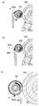
예를 들어, 전극 롤러, 대밍 롤러(damming roller), 블레이드 부재 및 액체 수용 용기가 제공되는 구성이 제안되었다(일본 공개 특허 출원 (JP-A) 2008-242436). JP-A 2008-242436에 기재된 구성에서는, 도 15의 (a)에 도시된 바와 같이, 액체 현상제는 전극 롤러(942)와 액체 수용 용기(941) 사이에 공급된다. 그리고, 전극 롤러(942)와 액체 수용 용기(941) 사이에 전압이 인가되는 상태에서 전극 롤러(942)가 회전함으로써, 토너가 전극 롤러(942)를 향해 끌어 당겨진다. 여기서, 액체 현상제가 통해서 공급되는 공급구(946a)가 실질적 수평 방향으로 위치설정되고, 전극 롤러(942)와 액체 수용 용기(941) 사이를 통과한 현상제는 중력 방향에 관해 공급구(946a)의 상방에 위치설정된 배출구(946b)를 통해 배출된 후 캐리어 탱크(도시되지 않음)에 보내진다.For example, a configuration has been proposed in which an electrode roller, a damming roller, a blade member, and a liquid accommodation container are provided (Japanese Laid Open Patent Application (JP-A) 2008-242436). In the configuration described in JP-A 2008-242436, as shown in Fig. 15A, a liquid developer is supplied between the
전극 롤러(942)의, 전극 롤러(942)의 회전 방향에 관한 배출구(946b)의 하류 측에서, 대밍 롤러(943)는 전극 롤러(942)와 접촉하여 배치되며, 따라서 전극 롤러(942)에 의해 반송(이송)된 액체 현상제가 대밍 롤러(943)에 의해 대밍된다. 대밍 롤러(943)의 더 하류의 위치에서, 블레이드 부재(944)는 전극 롤러(942)와 접촉하여 배치되고, 대밍 롤러(943)에 의해 대밍되지 않고 전극 롤러(942)의 회전에 의해 반송된 액체 현상제를 전극 롤러(942)의 표면으로부터 긁어낸다.On the downstream side of the
또한, 공급부(946a) 및 배출구(946b) 사이에는, 액체 현상제를 그 자체와 공급구(946a) 사이에서 순환시키는 다른 배출구(946c)가 제공된다. 액체 현상제는, 캐리어 액의 토너 함량(농도)이 미리결정된 값 이하가 될 때까지 배출구(946c)와 공급구(946a) 사이에서 순환되며 그 후 배출구(946b)를 통해 배출된다.Between the
JP-A 2008-242436에 기재된 구성의 경우에, 도 15의 (b)에 도시된 바와 같이, 액체 수용 용기(941)와 전극 롤러(942) 사이를 통해 액체 현상제가 통과하는 동안, 전극 롤러(942)의 표면에는, 가압된 토너(T) 층과 토너(T) 층 외측의 캐리어 액(C) 층이 형성된다. 전극 롤러(942)의 회전에 의해 반송되는 토너(T) 층 및 캐리어 액(C) 층은 전극 롤러(942)와 대밍 롤러(943) 사이를 통과한다. 이때, 캐리어 액(C) 층은 대밍 롤러(943) 측의 부분과 전극 롤러(942) 측의 부분으로 미리결정된 비율로 분할된다.In the case of the configuration described in JP-A 2008-242436, while the liquid developer passes through between the
여기서, 분리되어 대밍 롤러(943) 측에 반송된 캐리어 액(C) 층은 대밍 롤러(943)에 보유되고, 전극 롤러(942)와 대밍 롤러(943) 사이를 통과한 토너(T) 층은 블레이드 부재(944)에 의해 회수된다.Here, the layer of the carrier liquid (C), which is separated and conveyed to the side of the advancing
캐리어 액의 재사용 효율을 향상시키기 위해서, 현상제가 대밍 롤러(943)에 공급되는 위치가 전극 롤러의 표면이 상방으로부터 하방을 향해 이동하는 영역(0시 위치로부터 6시 위치까지)에 배치된다. 이 경우, 전극 롤러 상의 토너가 직접적으로 긁어내지는 구성이 채용되는 경우, 블레이드의 접촉 위치는 6시 위치 또는 그 이후이다. 일반적으로, 블레이드는 회수성을 향상시키기 위해서 전극 롤러의 회전 방향과 반대 방향으로 전극 롤러와 접촉하여 제공된다. 이런 이유 때문에, 블레이드에 의해 회수된 토너는 일부 경우에 블레이드를 따라 전극 롤러로 거꾸로 유동한다. 또한, 블레이드의 접촉 위치가 억제되고, 따라서 수평 방향에 관한 블레이드의 경사 각도가 작아진다. 결과적으로, 토너는 블레이드에 정체되고, 따라서 토너 회수성이 저하될 우려가 있었다.In order to improve the reuse efficiency of the carrier liquid, the position where the developer is supplied to the thickening
본 발명은 상술한 상황의 관점에서 달성되었으며, 본 발명의 주 목적은 캐리어 액과 토너 사이의 분리성을 향상시키는 것이다.The present invention has been achieved in view of the above-described situation, and the main object of the present invention is to improve the separability between the carrier liquid and the toner.
본 발명의 양태에 따르면, 전계를 사용하여 토너와 캐리어 액을 포함하는 액체 현상제로부터 토너와 캐리어 액을 분리하는 분리 장치가 제공되며, 상기 분리 장치는, 미리결정된 방향으로 회전가능한 전기전도성 전극 롤러; 상기 전극 롤러의 외주면과 자신 사이에 간극이 있는 상태로 제공되는 전극 부재로서, 상기 전극 부재는 상기 전극 롤러와 상기 전극 부재 사이에서 상기 전극 롤러를 향해 상기 토너를 이동시키기 위한 전계를 발생시키기 위해 전압을 인가할 수 있고, 상기 전극 롤러의 회전 방향에 관한 상기 간극의 상류 단부가 상기 중력 방향에 관하여 상기 회전 방향에 관한 상기 간극의 하류 단부의 상방에 제공되는, 전극 부재; 상기 간극의 상류 단부로부터 상기 간극 안으로 상기 액체 현상제를 공급하도록 구성되는 공급부; 상기 중력 방향에 관하여 상기 간극의 상류 단부 하방에 제공되고 상기 회전 방향에 관하여 상기 전극 부재의 하류 측에서 상기 전극 롤러로부터 상기 캐리어 액을 회수하도록 구성되는 회수부; 상기 회전 방향에 관하여 상기 전극 부재의 하류에 제공되고, 상기 전극 롤러에 대향하는 위치에서 상기 전극 롤러와 접촉하는 상태에서 상기 전극 롤러와 동일한 둘레 이동 방향으로 회전가능한 회수 롤러로서, 상기 회수 롤러는 상기 회수 롤러와 상기 전극 롤러 사이에서 상기 회수 롤러를 향해 상기 토너를 이동시키기 위한 전계를 발생시키기 위해 전압을 인가할 수 있는, 회수 롤러; 및 상기 회수 롤러의 회전 방향에 관하여 반대 방향으로 상기 회수 롤러에 접촉하는 상태에서 상기 회수 롤러로부터 상기 토너를 회수하도록 구성되는 블레이드 부재로서, 상기 중력 방향에 관하여 상기 전극 롤러의 최상부와 상기 전극 롤러의 중심을 통과하는 선이 0°일 경우, 상기 간극의 상류 단부는 상기 전극 롤러의 회전 방향에 관하여 0° 이상 180° 미만의 범위에 위치설정되며, 상기 중력 방향에 관한 상기 회수 롤러의 최상부 및 상기 회수 롤러의 중심을 통과하는 선이 0°일 때, 상기 회수 롤러와의 상기 블레이드 부재의 접촉 위치가 상기 회수 롤러의 회전 방향에 관하여 상기 전극 롤러와 상기 회수 롤러 사이의 접촉 위치의 상류 측의 35° 이상의 범위에 있는, 블레이드 부재를 포함한다. According to an aspect of the present invention, there is provided a separating device for separating a toner and a carrier liquid from a liquid developer containing a toner and a carrier liquid using an electric field, the separating device comprising an electroconductive electrode roller rotatable in a predetermined direction, ; Wherein the electrode member is provided between the electrode roller and the electrode roller so as to generate an electric field for moving the toner toward the electrode roller, And an upstream end of the gap with respect to the rotational direction of the electrode roller is provided above the downstream end of the gap with respect to the rotational direction with respect to the gravity direction; A supply configured to supply the liquid developer from the upstream end of the gap into the gap; A recovery unit provided below the upstream end of the gap with respect to the gravity direction and configured to recover the carrier liquid from the electrode roller at a downstream side of the electrode member with respect to the rotation direction; A recovery roller provided downstream of the electrode member with respect to the rotation direction and rotatable in the same circumferential movement direction as the electrode roller in a state of being in contact with the electrode roller at a position opposite to the electrode roller, A collecting roller capable of applying a voltage between the collecting roller and the electrode roller so as to generate an electric field for moving the toner toward the collecting roller; And a blade member configured to recover the toner from the collection roller in a state of being in contact with the collection roller in the opposite direction with respect to the rotation direction of the collection roller, The upstream end of the gap is positioned in a range of 0 占 to 180 占 with respect to the rotation direction of the electrode roller when the line passing through the center is 0 占 and the uppermost portion of the recovery roller with respect to the gravity direction, When the line passing through the center of the collection roller is at 0 °, the contact position of the blade member with the collection roller is set to be 35 ° on the upstream side of the contact position between the electrode roller and the collection roller with respect to the rotation direction of the collection roller Of the blade member.
본 발명의 추가적인 특징은 첨부된 도면을 참고한 예시적인 실시예에 대한 이하의 설명으로부터 명확해질 것이다.Further features of the present invention will become apparent from the following description of exemplary embodiments with reference to the accompanying drawings.
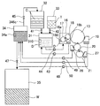
도 1은 본 발명의 실시예에서의 화상 형성 장치의 개략도이다.
도 2는 본 실시예의 화상 형성 장치에서의 액체 현상제의 반송 경로를 도시하는 개략도이다.
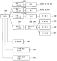
도 3은 본 실시예의 화상 형성 장치에서의 액체 현상제의 반송 동작의 제어 블록도이다.
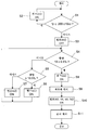
도 4는 본 실시예의 화상 형성 장치에서의 액체 현상제의 반송 동작의 제어를 도시하는 흐름도이다.
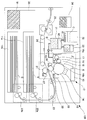
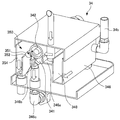
도 5는 본 실시예의 분리 및 추출 장치의 사시도이다.
도 6은 본 실시예의 분리 및 추출 장치를 도시하는 부분 절취 사시도이다.
도 7은 본 실시예의 분리 및 추출 장치의 일부를 도시하는 개략도이다.
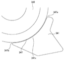
도 8은 도 7의 A 부분의 확대도이다.
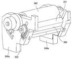
도 9는 본 실시예의 분리 및 추출 장치의 일부를 도시하는 사시도이다.
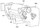
도 10은 도 9의 각도와 상이한 각도에서 본 본 실시예의 분리 및 추출 장치의 일부를 도시하는 사시도이다.
도 11은 본 실시예의 액체 현상제의 분리 및 추출 동작의 제어를 도시하는 흐름도이다.
도 12는 토너의 유동을 도시하기 위한 본 실시예의 분리 및 추출 장치의 일부를 도시하는 단면도이다.
도 13은 회수 롤러의 둘레부가 도시되어 있는 본 실시예의 분리 및 추출 장치의 다른 예를 도시하는 단면도이다.
도 14에서, (a) 내지 (c)는 각각 회수 롤러의 둘레부가 제1 내지 제3 예의 각각으로 도시되어 있는 본 실시예의 분리 및 추출 장치의 제1 내지 제3 예를 도시하는 단면도이다.
도 15에서, (a)는 종래예의 분리 및 추출 장치의 단면도이고, (b) 및 (c)는 각각 토너와 캐리어 액 사이의 관계를 각각 도시하는 도 15의 (a)의 B 부분 및 C 부분의 확대도이다.1 is a schematic view of an image forming apparatus in an embodiment of the present invention.
Fig. 2 is a schematic view showing the conveyance path of the liquid developer in the image forming apparatus of this embodiment. Fig.
3 is a control block diagram of the liquid developer conveyance operation in the image forming apparatus of this embodiment.
4 is a flow chart showing the control of the liquid developer conveyance operation in the image forming apparatus of this embodiment.
5 is a perspective view of the separating and extracting apparatus of this embodiment.
6 is a partially cutaway perspective view showing the separating and extracting apparatus of this embodiment.
7 is a schematic view showing a part of the separation and extraction apparatus of the present embodiment.
8 is an enlarged view of a portion A in Fig.
9 is a perspective view showing a part of the separating and extracting apparatus of this embodiment.
10 is a perspective view showing a part of the separating and extracting apparatus of the present embodiment seen from an angle different from the angle of FIG.
11 is a flow chart showing the control of the separation and extraction operation of the liquid developer in this embodiment.
12 is a sectional view showing a part of the separating and extracting apparatus of this embodiment for showing the flow of the toner.
13 is a sectional view showing another example of the separating and extracting apparatus of the present embodiment in which the peripheral portion of the collection roller is shown.
14, (a) to (c) are cross-sectional views showing first to third examples of the separation and extraction apparatus of this embodiment, in which the periphery of the collection roller is shown as each of the first to third examples, respectively.
15A and 15B are sectional views of the separating and extracting apparatus of the conventional example. Fig. 15B and Fig. 15C are a sectional view of the portion B and the portion C of Fig. 15A showing the relationship between the toner and the carrier liquid, As shown in FIG.
본 발명의 실시예를 도 1 내지 도 14를 사용하여 설명한다. 먼저, 본 실시예의 화상 형성 장치의 일반적인 구성을 도 1을 사용하여 설명한다. Embodiments of the present invention will be described with reference to Figs. 1 to 14. Fig. First, a general configuration of the image forming apparatus of this embodiment will be described with reference to Fig.
(화상 형성 장치)(Image forming apparatus)
본 실시예의 화상 형성 장치(100)는 기록재(시트, OHP 시트 등의 시트재 등)에 토너상을 형성하는 전자 사진 방식의 디지털 프린터이다. 화상 형성 장치(100)는 화상 신호에 기초하여 동작되고, 화상 형성부(12)에 의해 형성된 토너상이 카세트(11a, 11b) 각각으로부터 연속적으로 반송되는 기록재로서의 시트에 전사된 후 시트(S)에 정착됨으로써, 화상이 획득된다. 화상 신호는 도시되지 않은 스캐너 또는 도시되지 않은 퍼스널 컴퓨터 같은 외부 단말기로부터 보내진다.The
화상 형성부(12)는 상 담지체로서의 감광 드럼, 대전기(14), 레이저 노광 장치(15), 현상 장치(16) 및 드럼 클리너(19)를 포함한다. 대전기(14)에 의해 전기적으로 대전된 감광 드럼(13)의 표면이 제1 신호에 따라 레이저 노광 장치(15)로부터의 레이저 광(E)에 의해 조사됨으로써, 감광 드럼(13)에 정전 잠상이 형성된다. 이 정전 잠상은 현상 장치(16)에 의해 토너상으로서 현상된다. 본 실시예에서, 현상 장치(16)에는, 분산질인 분체 토너가 분산매인 캐리어 액에 분산되어 있는 액체 재료로서의 액체 현상제(D)가 수용되어 있고, 이 액체 현상제(D)를 사용하여 현상이 행해진다.The
액체 현상제(D)는 혼합 장치로서의 믹서(31)에서 미리결정된 비율로 캐리어 액(C)에 토너(T)를 혼합하고 분산시킴으로써 발생되며, 그 후 현상 장치(16)에 공급된다. 캐리어 액(C)은 캐리어 용기(회수 용기)로서의 캐리어 탱크(32)에 수용되며, 토너(T)는 토너 용기로서의 토너 탱크(33)에 수용된다. 그 후, 믹서(31)에서의 캐리어 액(C) 및 토너(T)의 혼합 상태에 따라, 캐리어 액(C) 또는 토너(T)가 연관된 탱크로부터 공급된다. 믹서(31)에는, 도시되지 않은 모터에 의해 구동되는 교반 블레이드가 수용되어 있으며, 현상제 액(D)이 교반에 의해 캐리어 액(C) 또는 토너(T)와 혼합됨으로서, 토너가 캐리어 액에 분산된다.The liquid developer D is generated by mixing and dispersing the toner T in the carrier liquid C at a predetermined ratio in the
믹서(31)로부터 현상 장치(16)에 공급되는 액체 현상제는 현상제 담지체로서의 현상 롤러(18)에 코팅(공급)되며 현상을 위해 사용된다. 현상 롤러(18)는 그 표면에서 액체 현상제(D)를 보유 및 반송하며, 토너에 의해 감광 드럼(13)(제1 담지체)에 형성된 정점 잠상을 현상한다. 현상 후에 현상 롤러(18)에 잔류하는 토너(T) 및 캐리어 액(C)은 현상 장치(16)의 회수 구간(16b)에서 회수된다. 여기서, 코팅 롤러(17)로부터 현상 롤러(18)에의 액체 현상제의 코팅과 현상 롤러(18)에 의한 감광 드럼(13)의 정전 잠상의 현상의 각각은 전계를 이용하여 이루어진다.The liquid developer supplied from the
감광 드럼(13)에 형성된 토너상은 전계를 이용하여 중간 전사 롤러(20)에 전사된 후에, 중간 전사 롤러(20) 및 전사 롤러(21)에 의해 형성되는 닙부에 반송된다. 중간 전사 롤러(20)에의 토너상 전사 후에 감광 드럼(13)에 잔류하는 캐리어 액(C) 및 토너(T)는 드럼 클리너(19)에 의해 회수된다. 또한, 중간 전사 롤러(20) 및 전사 롤러(21) 중 적어도 하나는 무단 벨트일 수도 있다.The toner image formed on the
카세트(11a, 11b) 각각에 수용된 시트(S)는 반송 롤러로 구성되는 연관된 반송부(22a 또는 22b)에 의해 레지스트레이션 반송부(23)를 향해 반송된다. 레지스트레이션 반송부(23)는 중간 전사 롤러(20)에 전사된 토너상의 타이밍에 맞춰 중간 전사 롤러(20)와 전사 롤러(21) 사이의 닙부에 시트(S)를 반송한다.The sheet S accommodated in each of the
중간 전사 롤러(20)와 전사 롤러(21) 사이의 닙부에서, 토너상은 닙부를 통과하는 시트(S)에 전사되며, 토너상이 전사된 시트(S)는 반송 벨트(24)에 의해 정착 장치(25)에 반송되며, 따라서 시트(S)에 전사된 토너상이 정착된다. 토너상이 정착된 시트(S)는 화상 형성 장치 외부로 배출됨으로써, 화상 형성 단계가 완료된다.At the nip between the
중간 전사 롤러(20) 및 전사 롤러(21)에는 각각 연관된 롤러에 잔류하는 캐리어 액(C) 및 토너(T)를 회수하기 위해 중간 전사 롤러 클리너(26) 및 전사 롤러 클리너(27)가 제공된다.The
(액체 현상제)(Liquid developer)
이어서, 액체 현상제에 대해 설명한다. 액체 현상제(D)로서, 종래 사용되는 액체 현상제가 사용될 수도 있지만, 본 실시예에서는 자외선경화성 액체 현상제(D)가 사용되며 이하에서 설명하다.Next, the liquid developer will be described. As the liquid developer (D), a conventionally used liquid developer may be used, but in this embodiment, an ultraviolet curable liquid developer (D) is used and will be described below.
액체 현상제(D)는 양이온-중합성 액체 단량체, 광중합 개시제, 및 양이온-중합성 액체 단량체에 불용성인 토너 입자를 포함하는 자외선경화성 액체 현상제이다. 양이온-중합성 액체 단량체는 비닐 에테르 화합물이며, 광중합 개시제는 이하의 화학식 1에 의해 표현되는 화합물이다.The liquid developer (D) is an ultraviolet curable liquid developer containing toner particles insoluble in a cation-polymerizable liquid monomer, a photopolymerization initiator, and a cation-polymerizable liquid monomer. The cation-polymerizable liquid monomer is a vinyl ether compound, and the photopolymerization initiator is a compound represented by the following formula (1).

구체적으로는, 먼저, 토너 입자는 착색제 및 착색제가 통합되는 토너 수지 재료를 포함한다. 토너 수지 재료 및 착색제와 함께, 대전 제어제 같은 다른 재료도 포함될 수 있다. 토너 입자의 제조 방법으로서는, 착색제가 분산되고 수지 재료가 서서히 중합되어 착색제가 중합체에 통합되는 코아세르베이션(coacervation) 또는 수지 재료 등이 용융되고 착색제가 용융된 수지 재료에 통합되는 내 분쇄법 같은 공지의 기술이 사용될 수도 있다. 토너 수지 재료로서, 에폭시 수지, 스티렌-아크릴 수지 등이 사용된다. 착색제는 범용 유기 및 무기 착색제일 수 있다. 상기 제조 방법에서, 토너 분산성을 향상시키기 위해서, 분산제가 사용되지만 상승작용제도 사용될 수 있다.Specifically, first, the toner particles include a toner resin material into which a colorant and a colorant are incorporated. In addition to the toner resin material and the colorant, other materials such as charge control agents may also be included. Examples of the method for producing the toner particles include a coacervation method in which a colorant is dispersed and a resin material is gradually polymerized to integrate a colorant into a polymer or a known method such as a crushing method in which a resin material is melted and a colorant is incorporated into a molten resin material May be used. As the toner resin material, an epoxy resin, a styrene-acrylic resin, or the like is used. The colorant may be a general organic or inorganic colorant. In the above production method, in order to improve the toner dispersibility, a dispersant is used, but a synergistic system can be used.
이어서, 캐리어 액인 경화성 액체는 토너 표면에 전하를 부여하기 위한 대전 제어제, 자외선(UV) 조사에 의해 산을 발생시키기 위한 광중합제(개시제), 및 상기 산에 의해 결합가능한 단량체로 구성된다. 단량체는 양이온 중합 반응에 의해 중합가능한 비닐 에테르 화합물이다. 광중합 개시제와 별도로, 증감제를 함유할 수도 있다. 광중합에 의해, 보존성이 저하하기 때문에, 양이온 중합 금지제를 10 내지 5000ppm의 양으로 첨가할 수도 있다. 이외에, 일부 경우에 대전 제어 보조제, 다른 첨가제 등을 사용할 수도 있다.Next, the curable liquid, which is a carrier liquid, is composed of a charge control agent for imparting a charge to the toner surface, a photopolymerization initiator (initiator) for generating an acid by ultraviolet (UV) irradiation, and a monomer capable of bonding by the acid. Monomers are vinyl ether compounds that can be polymerized by cationic polymerization. Apart from the photopolymerization initiator, a sensitizer may be contained. Since the preservability is lowered by photopolymerization, the cationic polymerization inhibitor may be added in an amount of 10 to 5000 ppm. In addition, in some cases, a charge control aid, other additives, or the like may be used.
현상제의 UV 경화제(단량체)는, 하나의 비닐 에테르 기를 갖는 약 10%(중량%)의 일관능성 단량체(이하의 화학식 2) 및 두 개의 비닐 에테르 기를 갖는 약 90%(중량%)의 이관능성 단량체(이하의 화학식 3)의 혼합물이다.The UV curing agent (monomer) of the developer contains about 10% (wt%) of a monofunctional monomer having one vinyl ether group (the following formula 2) and about 90% (wt%) of a difunctional Monomer (the following formula 3).
![]()
![]()

광중합 개시제로서, 이하의 화학식 4로 나타내는 0.1%의 화합물이 혼합된다. 이 광중합 개시제를 사용함으로써, 만족스러운 정착을 가능하게 하면서도, 이온성 광산 발생제를 사용하는 경우와 달리, 고저항의 액체 현상제가 얻어진다.As a photopolymerization initiator, 0.1% of a compound represented by the following formula (4) is mixed. By using this photopolymerization initiator, a liquid developer of high resistance can be obtained, unlike the case of using an ionic photoacid generator, while allowing satisfactory fixation.

또한, 양이온 중합성 액상 단량체는, 디클로로펜타디엔 비닐 에테르, 시클로헥산디메탄올 디비닐 에테르, 트리시클로데칸 비닐 에테르, 트리메틸올프로판 트리비닐 에테르, 2-에틸-1,3-헥사메디올 디비닐 에테르, 2,4-디에틸-1,5-펜탄디올 디비닐 에테르, 2-부틸-2-에틸-1,3-프로판디올 디비닐 에테르, 네오펜틸글리콜 디비닐 에테르, 펜타에리트리톨 테트라비닐 에테르, 및 1,2-데칸디올 디비닐 에테르를 포함하는 군으로부터 선택되는 화합물인 것이 바람직하다.Further, the cationic polymerizable liquid monomer may be at least one selected from the group consisting of dichloropentadiene vinyl ether, cyclohexanedimethanol divinyl ether, tricyclodecane vinyl ether, trimethylolpropane trivinyl ether, 2-ethyl-1,3-hexamediol divinyl ether Butyl 2,4-diethyl-1,5-pentanediol divinyl ether, 2-butyl-2-ethyl-1,3-propanediol divinyl ether, neopentyl glycol divinyl ether, pentaerythritol tetravinyl ether, And 1,2-decanediol divinyl ether.
또한, 대전 제어제로서는, 공지의 화합물을 이용할 수 있다. 구체적인 화합물로서는, 아마인유 및 대두유 같은 지방 및 오일; 할로겐 중합체; 방향족 폴리카르복실산, 산성기함유 수용성 염료 및 방향족 폴리아민 같은 산화 축합물; 나프텐산 코발트, 나프텐산 니켈, 나프텐산철, 나프텐산 아연, 옥틸산 코발트, 옥틸산 니켈, 옥틸산 아연, 도데실산 코발트, 도데실산 니켈, 도데실산 아연, 스테아르산 알루미늄, 및 2-에틸헥실산 코발트 등의 금속 비누류; 석유계 산 금속염 및 술포숙신산 금속염 등의 술폰산 금속염류; 레시틴 등의 인 지질; t-부틸살리실산 금속 착체 등의 살리실산 금속염류; 폴리비닐 피롤리돈 수지; 폴리아미드 수지; 술폰산함유 수지; 및 히드록시벤조산 유도체를 사용할 수 있다.As the charge control agent, known compounds can be used. Specific compounds include fats and oils such as linseed oil and soybean oil; Halogen polymers; Oxidative condensates such as aromatic polycarboxylic acids, water-soluble dyes containing an acidic group and aromatic polyamines; Cobalt naphthenate, cobalt naphthenate, nickel naphthenate, iron naphthenate, zinc naphthenate, cobalt octylate, nickel octylate, zinc octylate, cobalt dodecylate, dodecylic acid nickel, dodecanoic acid, aluminum stearate, Metal soaps such as cobalt; Metal salts of sulfonic acids such as petroleum-based metal salts and sulfosuccinic acid metal salts; Phospholipids such as lecithin; salicylic acid metal salts such as t-butylsalicylic acid metal complex; Polyvinyl pyrrolidone resins; Polyamide resins; Sulfonic acid-containing resin; And hydroxybenzoic acid derivatives can be used.
(액체 현상제의 반송)(Conveying liquid developer)
이어서, 본 실시예에서의 액체 현상제(D)의 반송에 대해서 도 2 내지 도 4를 사용하여 설명한다. 먼저, 상술한 바와 같이, 드럼 클리너(19), 중간 전사 롤러 클리너(26) 및 전사 롤러 클리너(27)를 포함하는 화상 형성부(12)에서 회수한 현상제는 토너와 캐리어 액 사이의 분리가 행해져서, 캐리어 액이 재이용된다. 또한, 현상 후에 현상 롤러(18) 상에 잔류하고, 현상 장치의 회수 구간(16b) 안으로 회수된 현상제는, 믹서(31)로 복귀되지만, 분리 및 추출 장치(34)에 반송될 수도 있다.Next, the conveyance of the liquid developer D in this embodiment will be described with reference to Figs. 2 to 4. Fig. First, as described above, the developer recovered in the
분리 및 추출 장치(34)는, 상세하게 후술하지만, 캐리어 액과 토너를 서로 분리할 때에, 재이용 가능한 캐리어 액과, 토너 및 종이 가루 등의 불순물을 포함하는 폐액(W)을 분리하고, 따라서 분리된 폐액(W)은 폐액 회수 용기(35)에 회수된다.The separating and extracting
구체적으로는, 캐리어 탱크(32)로부터 믹서(31)에의 수송관과 토너 탱크(33)로부터 믹서(31)에의 수송관에는 각각 전자기 밸브(41, 42)가 제공되고, 믹서(31)에의 캐리어 액(C)의 공급량과 믹서(31)에의 토너(T)의 공급량을 조정한다. 믹서(31)로부터는, 펌프(44)를 사용해서 현상에 필요한 액체 현상제(D)가 공급된다.Specifically, the transport pipe from the
현상 장치(16)의 회수 용기(16b)에 회수한 현상제는 펌프(43)에 의해 믹서(31)로 복귀된다. 이는 회수 용기(16b)에 회수된 현상제는 현상 등에 거의 사용되지 않고 따라서 거의 열화되어 있지 않기 때문이다.The developer recovered in the
드럼 클리너(19), 중간 전사 롤러 클리너(26) 및 전사 롤러 클리너(27)에 의해 회수된 잔류 캐리어 액 및 잔류 토너는 각각 펌프(48, 49, 50)에 의해 분리 및 추출 장치(34)에 반송된다.The residual carrier liquid and the residual toner recovered by the
분리 및 추출 장치(34)에 의해 분리된 재이용가능한 캐리어 액은 전자기 밸브(45)에 의해 캐리어 탱크(32)에 반송된다. 한편, 분리 및 추출 장치(34)에 의해 분리된 폐액은 자중 낙하를 통해 수송관에 제공된 전자기 밸브(47)에 의해 폐액 회수 용기(35)에 적절히 반송된다.The reusable carrier liquid separated by the separating and extracting
액체 현상제 등의 수송은, 펌프의 사용 이외에, 예를 들어 액체 현상제 등을 자중 낙하에 의해 반송할 수 있는 경우에는 액체 현상제의 자중을 사용한 반송 방식으로 이루어질 수도 있다.In addition to the use of a pump, for example, when the liquid developer or the like can be conveyed by self-falling, the conveyance of the liquid developer may be carried out using a self-weight of the liquid developer.
도 3에 도시한 바와 같이, 상술한 펌프(43, 44, 48, 49, 50) 및 전자기 밸브(41, 42, 45, 47)는 제어부로서의 CPU(200)에 의해 각각 펌프 드라이버(201) 및 전자기 밸브 드라이버(202)를 통해 제어된다. CPU(200)는, 현상제량 검출 장치(160), 고형 성분 함량 검출 장치(310), 및 캐리어 액 함량 검출 장치(34a)의 검출값에 기초하여 각 펌프 등을 제어하고 있다.3, the above-described
액체 현상제의 반송 동작에 대해서 도 2 및 도 3을 참조하면서 도 4를 사용해서 설명한다. 먼저, 도 2 및 도 3에 도시한 바와 같이, 현상 장치(16)에는 현상제량 검출 장치(160)가 제공되고, 현상제량 검출 장치(160)에 의해 현상 장치(16) 내의 액체 현상제의 양을 검출하고 있다. 또한, 믹서(31)에는 고형 성분 함량 검출 장치(310)가 제공되고, 따라서 믹서(31) 내의 토너 등의 고형 성분 함량을 검출하고 있다. 고형 성분 함량 검출 장치(310)는, 예를 들어 발광부와 수광부를 구비하고, 믹서(31) 내의 액체가 통과하는 부분에 발광부로부터 광을 조사하고, 이 부분을 투과한 광을 수광부에 의해 수광한다. 이 부분의 고형 성분의 양에 따라, 수광부에서 수광하는 광량이 변화하기 때문에, 이 광량의 변화에 따라 믹서(31) 내의 고형 성분의 함량을 검출할 수 있다.The conveying operation of the liquid developer will be described with reference to Figs. 2 and 3, with reference to Fig. 4. Fig. 2 and 3, the developing
도 4에 도시한 바와 같이, 현상 장치(16) 내의 현상제량을 현상제량 검출 장치(160)에 의해 검출한다(S1). 그리고, 현상 장치(16) 내의 현상제량이 미리결정된 양(예를 들어, 200±10cc) 이하인 경우에는, CPU(200)이 펌프(44)를 구동해서(S2), 현상 장치(16) 내의 액체 현상제량의 조정을 행한다. 조정 후에는, 펌프(44)의 구동을 정지한다(S3).As shown in Fig. 4, the amount of the developer in the developing
계속해서, 믹서(31) 내의 고형 성분의 함량을 고형 성분 함량 검출 장치(310)에 의해 검출한다(S4). 믹서(31) 내의 고형 성분의 함량이 미리결정된 범위(예를 들어, 10±0.5%)로부터 벗어날 경우에는, CPU(200)는 고형 성분 함량이 10.5% 이상인지의 여부를 판단한다(S5). 고형 성분 함량이 10.5% 이상인 경우에는, 전자기 밸브(41)를 개방하여, 캐리어 탱크(32)로부터 믹서(31) 내에 캐리어 액을 공급한다(S6). 한편, 고형 성분 함량이 10.5% 이상이 아닌 경우, 즉 고형 성분 함량이 9.5% 이하인 경우에는, 전자기 밸브(42)를 개방하여, 토너 탱크(33)로부터 믹서(31) 내에 토너를 공급한다(S7). 결과적으로, 믹서(31) 내의 액체 현상제의 함량 조정을 행한다.Subsequently, the content of the solid component in the
즉, 토너 함량(고형 성분 함량)이 높은 경우에는, 캐리어 액이 캐리어 탱크(32)로부터 전자기 밸브(41)를 통해 믹서(31)에 공급된다. 또한, 토너 함량이 낮은 경우에는, 믹서(31)에서 사용되는 액체 현상제보다 토너 함량이 높은 액체 현상제가 전자기 밸브(42)를 통해 토너 탱크(33)로부터 믹서(31)에 공급된다.That is, when the toner content (solid component content) is high, the carrier liquid is supplied from the
믹서(31) 내의 고형 성분 함량이 미리결정된 범위 내이면, 필요에 따라 펌프(44)를 구동하고, 함량 조정이 이루어진 액체 현상제를 믹서(31)로부터 현상 장치(16)에 공급한다(S8). 그리고, 화상 형성이 개시되고(S9), 동시에 펌프(43, 48, 49, 50)의 구동도 개시되며(S10), 또한 분리 및 추출 장치(34)의 구동도 개시된다(S11).If the solid component content in the
(분리 및 추출 장치)(Separation and extraction device)
다음에, 도 5 내지 도 11을 사용하여, 분리 장치로서의 분리 및 추출 장치(34)에 대해서 상세하게 설명한다. 분리 및 추출 장치(34)는, 전계를 사용하여 액체 현상제를 토너와 캐리어 액으로 분리하고, 캐리어 액과 토너를 따로따로 추출하는 장치이다.Next, the separation and
상술한 바와 같이, 드럼 클리너(19) 등의 화상 형성부(12)에서 회수된 액체 현상제는 도 5 및 도 6에 화살표로 나타낸 바와 같이 분리 및 추출 장치(34)의 입구(34b)로부터 액체 수용 용기(346) 내에 반송된다. 그리고, 액체 현상제는 액체 수용 용기(346) 내의 버퍼 용기(348)에 공급된다. 본 실시예에서는, 버퍼 용기(348)는 분리 및 추출 장치(34)에 제공되지만, 단일 부재로서 별도로 제공될 수도 있다. 버퍼 용기(348)에 공급된 액체 현상제는 펌프(34c)에 의해 반송되고, 필터(34d)를 통과한다.As described above, the liquid developer recovered in the
필터(34d)를 통과한 액체 현상제는, 도 6에 도시한 바와 같이, 공급부로서의 공급 트레이(346a)에 주입된다. 상세하게는 후술하는 바와 같이, 공급 트레이(346a)에 주입된 액체 현상제는 분리 및 추출 장치(34)에 의해 토너와 캐리어 액으로 분리된다. 그리고, 추출된 토너는 폐액 회수 용기(35)에 보내지고, 추출된 캐리어 액은 캐리어 탱크(32)에 반송된다.The liquid developer that has passed through the
이어서, 이러한 분리 및 추출 장치(34)에서의 토너와 캐리어 액의 분리 및 추출의 구성에 대해서 설명한다. 도 6 및 도 7에 도시한 바와 같이, 액체 수용 용기(346) 내에는, 외부 전극 부재로서의 코팅 전극 부재(341), 도전성의 롤러로서의 전극 롤러(342), 토너 회수 장치(350) 등이 제공된다. 액체 수용 용기(346)는, 액체 현상제를 수용할 수 있는 용기이며, 상술한 공급 트레이(346a), 후술하는 바와 같이 재이용가능한 캐리어 액이 배출되는 배출부(346b), 및 폐액인 현상제를 회수하는 회수부(354)를 갖고 있다.Next, the configuration of separation and extraction of the toner and carrier liquid in the separation and
전극 롤러(342)는, 예를 들어 중실 스테인리스강 재료에 의해 40 mm의 외경으로 형성된 코어 금속 표층을 코어 금속의 표면에 형성된 우레탄 고무 탄성층과 일체로 성형함으로써 형성되는 전도성 롤러이다. 도 3에 도시한 바와 같이, 구동력이 구동 모터(205)에 의해 전극 롤러(342)에 외부에서 입력되고, 따라서 전극 롤러(342)는 미리결정된 방향(도 6 및 도 7의 화살표 방향)으로 회전한다. 본 실시예에서는, 구동 모터(205)의 회전 속도는 2000rpm이다. 그리고, 전극 롤러(342)는, 구동 모터(205)의 회전 속도를 감속기에 의해 감속시킴으로써 예를 들어 400rpm의 회전 속도로 회전한다. 또한, 전압 인가 장치(345)는 고전압 드라이버(204)를 통해 CPU(200)에 의해 제어되며, 구동 모터(205)는 모터 드라이버(203)를 통해 CPU(200)에 의해 제어된다.The
코팅 전극 부재(341)는, 도 7 및 도 8에 도시한 바와 같이, 전극 롤러(342)의 일부와 간극(347)을 두고 배치된다. 전극 롤러(342)의 회전 방향에 관해 간극(347)의 상류 단부(347a)에는, 공급 트레이(346a)가 연결되어 있다. 또한, 상술한 바와 같이 공급 트레이(346a)에 주입된 액체 현상제는 상류 단부(347a)를 통해 간극(347) 내에 공급된다. 간극(347)은 전극 롤러(342)의 회전 축선 방향에 관해 그 양 단부에서 밀봉되어 있고, 따라서 간극(347) 안으로 공급된 액체 현상제는 단부 롤러(342)의 회전에 따라 전극 롤러(342)의 회전 방향에 관한 간극(347)의 하류측을 향해 간극(347)을 통해 반송된다. 간극(347)의 전극 롤러(342)의 회전 방향에 관한 하류 단부(347a)에는, 배출부(346b)가 연결되어 있다(도 6 참조). 또한, 간극(347)을 통과한 액체 현상제가 수송관(346c)을 경유하여 배출부(346b)를 통해 캐리어 탱크(32)로 보내진다(도 2 및 도 6).The
또한, 수송관(346c)은, 배출된 액체 현상제를 다시 분리 및 추출 장치(34)로 복귀시키는 경로에도 연결되어 있다. 배출부(346b)에는 캐리어 액 함량 검출 장치(34a)가 제공되고, 따라서 배출부(346b) 내에 보내진 액체 현상제의 캐리어 액 중의 토너 함량이 검출된다. 캐리어 액 함량 검출 장치(34a)의 구성은 전술한 고형 성분 함량 검출 장치(310)의 구성과 동일하다. 또한, 배출부(346b)에 보내진 액체 현상제의 토너 함량이 미리결정된 값(예를 들어, 0.02%)보다 큰 경우에는, 액체 현상제는 다시 분리 및 추출 장치(34)로 복귀되고, 따라서 토너와 캐리어 액으로의 액체 현상제의 분리가 행해진다.The
이것은, 예를 들어 분리 및 추출 장치(34)의 작동 중에 전원이 중단되는 등의 이상 상황이 발생하고, 따라서 캐리어 액 및 토너가 분리 및 추출 장치(34)에 의해 서로 충분히 분리될 수 없는 경우가 상정되기 때문이다. 이러한 경우, 배출부(346b)에 보내지는 액체 현상제의 토너 함량은 미리결정된 값보다 크기 때문에, 이 경우에는 액체 현상제가 분리 및 추출 장치(34)로 복귀된다. 통상은, 후술하는 바와 같이, 액체 현상제가 간극(347)을 통과함으로써, 토너와 캐리어 액이 서로로부터 분리되고, 추출된 캐리어 액이 배출부(346b)에 보내진다. 따라서, 배출부(346b)에 보내진 액체 현상제의 토너 함량은 미리결정된 값 이하이고, 따라서 캐리어 액은 분리 및 추출 장치(34)로 복귀되지 않고 캐리어 탱크(32)로 보내진다. 또한, 캐리어 액을 분리 및 추출 장치(34)로 복귀시키는 이러한 경로는 생략해도 된다.This is because, for example, an abnormal situation such as power interruption occurs during operation of the separating and extracting
상술한 바와 같이, 간극(347)을 두고 전극 롤러(342)에 대향하여 배치되는 코팅 전극 부재(341)는, 적어도 액체가 간극(347)을 통과하는 부분(341x)의 표면에서 도전성 재료로 형성된다. 코팅 전극 부재(341)는 예를 들어 400 mm 폭의 중실 스테인리스강 재료로 형성된다. 액체가 통과하는 부분(341x)은, 전극 롤러(342)의 일부를 수용하는 형상을 갖고, 이 부분(341x)의 전극 롤러(342)에 대한 대향 면은, 전극 롤러(342)의 표면과 대향 면 사이에 미리결정된 거리(즉, 간극(347))을 유지하도록 만곡된 형상을 갖는다. 이 미리결정된 거리는 예를 들어 0.2 mm이다.As described above, the
도 3에 도시한 바와 같이, 코팅 전극 부재(341)와 전극 롤러(342)에는, 전압 인가 수단으로서의 전압 인가 장치(345)가 연결되어 있다. 또한, 코팅 전극 부재(341)와 전극 롤러(342) 사이에는, 토너를 전극 롤러(342) 측을 향해 이동시키는 전계가 발생하도록 전압 인가 장치(345)에 의해 전압이 인가된다. 즉, 간극(347)에는, 토너를 전극 롤러(342)에 끌어당기는 전계가 발생하도록 하는 전압이 인가된다.As shown in Fig. 3, a
본 실시예에서는, 대전 제어제에 의해 토너가 음으로 대전되기 때문에, 예를 들어 전극 롤러(342)에는 -300V의 전압이 인가되며, 코팅 전극 부재(341)에는 -1000V의 전압이 인가된다. 따라서, 간극(347)을 통과하는 액체 현상제 중의 토너가 코팅 전극 부재(341)로부터 전극 롤러(342)에 이동된다. 이 결과, 액체 현상제가 간극(347)을 통과하고 있는 동안에, 토너가 전극 롤러(342)에 담지되어, 토너와 캐리어 액이 서로 분리된다. 분리된 캐리어 액은, 간극(347)의 하류 단부(347b)에 연결되는 배출부(346b)에 배출되고, 상술한 바와 같이 회수 용기로서의 캐리어 탱크(32)에 보내진다.In this embodiment, since the toner is negatively charged by the charge control agent, for example, a voltage of -300 V is applied to the
토너 회수 장치(350)는, 전극 롤러(342)의 회전 방향에 관해서 코팅 전극 부재(341)의 하류 측에 위치결정되고, 전극 롤러(342)에 담지된 토너를 회수한다. 토너 회수 장치(350)는, 회수 롤러(351), 회수 전압 인가 수단으로서의 전압 인가 장치(345), 및 긁어내기 부재로서의 블레이드 부재(352)를 갖는다.The
회수 롤러(351)는, 예를 들어 외경 20 mm의 중실 스테인리스강 재료로 형성된 도전성 롤러이며, 전극 롤러(342)에 접촉하도록 제공된다. 또한, 회수 롤러(351)는, 전극 롤러(342)에 접촉하고, 도 6 및 도 7의 화살표 방향으로 전극 롤러(342)에 의해 회전된다. 또한, 회수 롤러(351)의 회전 속도는 예를 들어 800rpm이다.The
전극 롤러(342) 및 회수 롤러(351)는, 도 9 및 도 10에 도시한 바와 같이, 서로 실질적으로 평행하게 배치되고, 회전 축선 방향에 관한 이들 롤러(342, 351)의 양 단부는 액체 수용 용기(346)를 구성하는 프레임(346e)에 의해 회전가능하게 지지된다. 회수 롤러(351)의 양 단부에는, 스프링 등의 가압 기구(353)가 제공된다. 회수 롤러(351)는, 가압 기구(353)에 의해 전극 롤러(342)를 향해서 가압되어, 전극 롤러(342)를 탄성 변형시키고 있다. 가압 기구(353)에 의한 회수 롤러(351)를 전극 롤러(342)를 향해 가압하는 가압력은 예를 들어 3kgf(29.4N)이다.The
코팅 전극 부재(341) 및 회수 롤러(351)는 전극 롤러(342)에 기초하여 위치결정되므로, 전극 롤러(342)는 이들 부재(341, 351)에 기초하여 위치결정된다.The
전압 인가 장치(345)는, 도 3에 도시한 바와 같이, 전극 롤러(342)와 회수 롤러(351)에 연결되어 있고, 토너를 회수 롤러(351)를 향해 이동시키는 전계가 발생하도록 회수 롤러(351)와 전극 롤러(342) 전압을 인가한다. 본 실시예에서는, 전극 롤러(342)와 회수 롤러(351)에 연결되는 전압 인가 장치 및 전극 롤러(342)와 코팅 전극 부재(341)에 연결되는 전압 인가 장치는 공통으로 사용되지만, 별도로 제공될 수도 있다. 본 실시예에서는, 예를 들어 전극 롤러(342)에는 -300V의 전압이 인가되며, 회수 롤러(351)에는 -200V의 전압이 인가된다. 따라서, 전극 롤러(342)에 담지되고, 회수 롤러(351)를 향해 반송되는 토너는 전극 롤러(342)로부터 회수 롤러(351)에 이동된다.3, the
블레이드 부재(352)는, 회수 롤러(351)에 접촉해서 회수 롤러(351) 상의 토너를 긁어낸다. 블레이드 부재(352)는, 블레이드 부재(352)가 회수 롤러(351)의 회전 방향에 대해 반대 방향으로 회수 롤러(351)에 접촉하도록, 회수 롤러(351)의 회전 방향에 관해 전극 롤러(342)와 회수 롤러(351) 사이의 접촉 위치의 하류 위치에 배치된다. 블레이드 부재(352)는 그 자유 단부(351a)가 회수 롤러(351)의 표면에 접촉하도록 가압된다. 또한, 반대 방향이란, 회수 롤러(351)의 표면에 접촉하는 자유 단부(352a)가 연장되는 방향이 회수 롤러(351)의 회전 방향을 따르는 접선 방향과 반대 방향이 되는 방향이다. 또한, 블레이드 부재(352)는 회수 롤러(351)의 길이 방향(회전 축선 방향)을 따라 연장하는 판(상) 부재이며, 예를 들어 스테인리스강 재료가 회수 롤러(351)의 재료로서 사용된다.The
상술한 바와 같이, 전극 롤러(342)로부터 회수 롤러(351)에 이동된 토너는 블레이드 부재(352)에 의해 긁어내지고, 토너 회수부로서의 회수부(354)에 보내진다. 회수부(354)에 회수된 토너는 상술한 바와 같이 폐액 회수 용기(35)에 보내진다. 또한, 회수 롤러(351)로부터 토너를 긁어내는 긁어내기 부재는 블레이드 부재로 한정되지 않는다. 예를 들어, 블레이드 부재는 또한 블레이드 형상 이외의 브러시 형상으로 형성될 수 있다.As described above, the toner moved from the
(간극의 양 단부 사이의 위치 관계)(Positional relationship between both ends of the clearance)
본 실시예의 경우, 상술한 바와 같이, 화상 형성부(12)에 회수되고, 공급 트레이(346a)로부터 간극(347)에 공급된 액체 현상제는 간극(347)을 통과함으로써, 액체 현상제는 토너와 캐리어 액으로 분리된다. 여기서, 액체는 중력 방향을 따라서 상방으로부터 하방으로 흐른다. 이로 인해, 간극(347)을 통과한 액체 현상제가 배출되는 하류 단부(347b)(출구)는 액체 현상제가 간극(347)에 공급되는 상류 단부(347a)(입구)보다 중력 방향에 관한 상방에 위치결정되는 것은 바람직하지 않다. 유사한 이유로, 대출부(346b)은 중력 방향에 관해 상류 단부(347a)(입구) 상방에 위치설정된다.In the case of this embodiment, as described above, the liquid developer recovered in the
특히, 캐리어 액의 재이용률을 향상시키기 위해서는, 토너를 긁어내기 부분(블레이드 부재(352)의 접촉 위치)의 현상제의 T/D비(토너와 캐리어 액 사이의 혼합비)가 최대한으로 증가되는 것이 바람직하다. 그러나, T/D비가 높은 액체 현상제는 높은 점도를 갖기 때문에, 현상제 반송성이 저하되고, 따라서 간극(347)의 출구가 간극(347)의 상방에 위치결정될 때, 재활용 효율이 저하된다.Particularly, in order to improve the reusability of the carrier liquid, it is necessary to maximize the T / D ratio (mixing ratio between the toner and the carrier liquid) of the developer at the portion where the toner is scratched (the contact position of the blade member 352) desirable. However, since the liquid developer having a high T / D ratio has a high viscosity, the conveyability of the developer is lowered, and when the outlet of the
그래서, 본 실시예에서는, 도 7에 도시한 바와 같이, 중력 방향에 관해 전극 롤러(342)의 중심(O)과 전극 롤러(342)의 최상부를 통과하는 선(α)이 0°인 경우에, 간극(347)의 상류 단부(347a)는 전극 롤러(342)의 회전 방향에 관해 0° 이상 180° 미만의 범위에 위치결정된다. 즉, 간극(347)의 상류 단부(347a)와 중심(O)을 통과하는 선(β)과 선(α) 사이에 형성되는 각도가 θ인 경우, 상류 단부(347a)는 각도(θ)가 0° 이상 180° 미만이 되도록 위치결정된다. 바람직한 예에서, 간극(347)의 상류 단부(347a)는, 전극 롤러(342)의 회전 방향에 관해 60° 이상 120° 이하의 범위에 위치결정된다. 본 실시예에서는, 상류 단부(347a)가 전극 롤러(342)의 회전 방향에 관해 90° 내지 120°의 범위에 위치결정된다.7, in the case where the line alpha passing through the center O of the
간극(347)의 하류 단부(347b)는 중력 방향에 관해 상류 단부(347a)보다 하방에 위치결정된다. 바람직한 예에서, 간극(347)의 하류 단부(347b)는 전극 롤러(342)의 회전 방향에 관해서 180° 이하의 범위에 위치결정된다. 즉, 하류 단부(347b)는 180°의 위치를 포함하는 범위에 위치결정되고, 하류 단부(347b)는 전극 롤러(342)의 회전 방향에 관해 180°의 위치의 상류에 위치결정되는 것이 바람직하다. 결과적으로, 간극(347)을 통과하는 액체 현상제가 중력에 대항하여 반송되는 것이 방지되므로, 재이용 효율이 더 향상될 수 있다. 본 실시예에서는, 하류 단부(347b)는 전극 롤러(342)의 회전 방향에 관해 180°의 위치에 있다.The
또한, 간극(347)의 길이, 즉 전극 롤러(342)를 따른 상류 단부(347a)로부터 하류 단부(347b)까지의 길이는 전극 롤러(342)의 외주면의 둘레 길이의 1/5 이상인 것이 바람직하다. 이 간극(347)의 길이는 전극 롤러(342)의 회전 속도에 따라서 설정될 수도 있다. 예를 들어, 전극 롤러(342)의 회전 속도가 느린 경우에는, 간극(347)의 길이를 짧게 할 수 있다. 요컨대, 액체 현상제가 간극(347)을 통과하는 동안에 토너와 캐리어 액이 서로 분리되는 길이가 확보되면 된다.The length of the
(액체 현상제의 분리 및 추출의 동작의 제어 플로우)(Control flow of operation of separation and extraction of liquid developer)
이어서, 상술한 바와 같이 구성되는 본 실시예에서의 액체 현상제의 분리 및 추출의 동작의 제어 플로우에 대해서 도 11 및 도 12를 사용해서 설명한다. 먼저, 각 펌프(48, 49, 50)가 구동됨으로써, 드럼 클리너(19), 중간 전사 롤러 클리너(26) 및 전사 롤러 클리너(27)에 의해 회수된 현상제가 분리 및 추출 장치(34)에 반송된다. 그리고, 미리결정된 양의 현상제가 분리 및 추출 장치(34)에 보내진 후, 펌프(48, 49, 50)의 구동은 정지된다(S21).Next, the control flow of the operation of separating and extracting the liquid developer in the present embodiment constituted as described above will be described with reference to Figs. 11 and 12. Fig. The developer recovered by the
계속해서, 구동 모터(205)의 구동을 개시하여, 전극 롤러(342)를 회전시킨다(S22). 이에 의해, 액체 현상제가 전극 롤러(342)의 회전에 따라 반송된다. 이때, 회수 롤러(351)는 전극 롤러(342)에 의해 회전된다. 또한, 전압 인가 장치(345)가 ON된다(S23). 이에 의해, 토너를 전극 롤러(342)를 향해 이동시키기 위한 전계가 발생되도록 코팅 전극 부재(341)와 전극 롤러(342) 사이에 전압이 인가되며, 토너를 회수 롤러(351)를 향해 이동시키기 위한 전계가 발생되도록 회수 롤러(351)와 전극 롤러(342) 사이에 전압이 인가된다. 이 때문에, 액체 현상제 중의 토너는 먼저 전극 롤러(342)를 향해 이동된 후에 회수 롤러(351)를 향해 이동된다. 전하를 갖지 않은 캐리어 액은 코팅 전극 부재(341) 측에 잔류한다.Subsequently, the driving of the driving
즉, 도 12에 도시된 바와 같이, 간극(347)을 통과하는 액체 현상제 중의 토너(T)(도 12에서 실선)는, 전극 롤러(342)에 전기적으로 끌어당겨 질 뿐만 아니라 코팅 전극 부재(341)로부터 전기적인 반발력을 받는다. 이에 의해, 토너(T)는 전극 롤러(342)를 향해 전기적으로 가압된다. 이때, 도 15의 (b)에 도시된 상술한 경우와 마찬가지로, 토너(T) 층은 전극 롤러(342) 측에 위치설정되며, 캐리어 액(C) 층은 토너(T) 층에 위치설정된다. 전극 롤러(342)의 회전에 의해, 토너(T) 층 및 캐리어 액(C) 층을 포함하는 액체는 회수 롤러(351)에 대향하는 위치에 반송되며, 그 후 토너(T) 층은 전계에 의해 회수 롤러(351)에 이동된다.12, the toner T (solid line in Fig. 12) in the liquid developer passing through the
간극(347)을 통과하고 전극 롤러(342)에 의해 회수 롤러(351)에 반송된 토너(T)는 회수 롤러(351)에 전기적으로 끌어당겨 질 뿐만 아니라 전극 롤러(342)로부터 전기적 반발력을 받는다. 결과적으로, 토너는 전극 롤러(342)로부터 이격되는 방향, 즉 회수 롤러(351)를 향하는 방향으로 전기적으로 가압된다. 이때, 캐리어 액(C)은 미리결정된 비율로 전극 롤러(342) 측의 부분과 회수 롤러(351) 측의 부분으로 분할되고, 따라서 전극 롤러(342) 측의 분할된 캐리어 액(C) 층(도 12의 쇄선)은 전극 롤러(342)의 회전에 의해 간극(347)의 상류 단부(347a)에 반송된다. 즉, 전극 롤러(342)와 회수 롤러(351) 사이의 전극 롤러(342) 측의 분할된 캐리어 액(C)은 입구에 복귀된다. 그 후, 캐리어 액(C)은 공급 트레이(346a)로부터 공급되는 액체 현상제와 합쳐지고 그 후 간극(347) 안으로 다시 반송된다.The toner T that has passed through the
회수 롤러(351)에 전기적으로 부착된 토너는 블레이드 부재(352)에 의해 긁어내어 진다. 여기서, 전자기 밸브(47)가 개방된다(S24). 이에 의해, 블레이드 부재(352)에 의해 긁어내진 토너는, 그 자중에 의해 낙하하고 회수부(354)를 통해 폐액 회수 용기(35)에 회수된다. 또한, 토너는 폐기되거나 재이용될 수 있다.The toner electrically attached to the
또한, 간극(347)의 하류 단부(347b)를 통해 배출부(346b)에 배출된 캐리어 액은 캐리어 액 함량 검출 장치(34a)에 의해 토너 함량이 검출되고, 검출된 토너 함량이 미리결정된 값(예를 들어, 0.02%) 이하인지의 여부가 판단된다(S25). 토너 함량이 미리결정된 값 이하이면, 전자기 밸브(45)가 개방되어, 캐리어 액이 캐리어 탱크(32)에 보내진다(S26).The carrier liquid discharged to the
그리고, 분리 및 추출 장치(34)로부터의 캐리어 액의 분리 및 추출이 완료되면(S27), 전자기 밸브(45, 47)가 폐쇄되고(S28), 전압 인가 장치(345) 및 구동 모터(205)가 순차 정지된다(S29, S30).When the separation and extraction of the carrier liquid from the separation and
계속해서, 펌프(48, 49, 50)에 의해 미리결정된 양의 잔류 현상제가 다시 분리 및 추출 장치(34)에 반송되고, 후속 분리 처리가 행하여진다. 그 후, 이러한 동작이 반복된다.Subsequently, a predetermined amount of the residual developer is returned to the separating and extracting
본 실시예의 분리 및 추출 장치(34)에서는, 액체 현상제 100.0cc(캐리어 액 90.0cc 및 토너 10.0cc 함유)로부터, 88.0cc의 캐리어 액을 추출할 수 있다. 1회의 분리 처리에서의 요구 시간은 예를 들어 30초이며, 이 경우 800 mm/s의 처리 속도를 충족할 수 있다.In the separation and
(블레이드 부재의 배치)(Arrangement of blade member)
블레이드 부재(352)의 배치에 대해서 도 12 내지 도 14를 사용하여 설명한다. 상술한 바와 같이, 블레이드 부재(352)는 회수 롤러(351)에 이동된 토너를 긁어낸다. 블레이드 부재(352)는 블레이드 부재(352)가 회수 롤러(351)에 대해 반대 방향으로 연장되고 블레이드 부재(352)가 회수 롤러(351)의 접선 방향을 따라 회수 롤러(351)에 접촉하도록 제공된다. 회수 롤러(351)에 접촉하는, 블레이드 부재(352)의 자유 단부(352a)가 중력 방향에 관해 회수 롤러(351)의 상위 절반 표면(부분)에 있는 경우, 블레이드 부재(352)는 이하의 방식으로 배치된다. 즉, 중력에 의해 블레이드 부재(352)에 토너(T)를 이동시키기 위해서, 블레이드 부재(352)는 블레이드 부재(352)가 지지되는 자유 단부(352a)가 상위 측에 위치설정되고 그 기부 단부가 중력 방향에 관한 하위 측에 위치설정되도록 배치된다. 즉, 블레이드 부재(352)는 자유 단부(352a)가 중력 방향에 관해 기부 단부 상방에 위치되도록 배치된다.The arrangement of the
이때, 블레이드 부재(352)가 회수 롤러(351)에 접촉하는 각도에 따라 토너(T) 층이 블레이드 부재(352)에 정체될 가능성이 있다. 예를 들어, 도 13에 도시된 바와 같이, 블레이드 부재(352)가 수평 방향에 관한 블레이드 부재(352)의 각도(θ1)가 대략 35° 이하(θ1≤35°)가 되는 자세에 있는 경우, 토너는 블레이드 부재(352) 상에서 쉽게 움직이지 않는다. 또한, 도 13의 화살표 방향(반시계 방향)으로 회전하는 회수 롤러(351)에서는, 블레이드 부재(352)의 자유 단부(352a)의 상류 부분에서, 토너(T)가 응집부(T-t)를 형성하면서 정체되기 쉽다.At this time, there is a possibility that the toner (T) layer stagnates on the
상술한 바와 같은 토너(T)의 정체를 억제하기 위해서, 블레이드 부재(352)의 자유 단부(352a)가 중력 방향에 관하여 회수 롤러(351)의 상위(-절반) 표면에 있을 때, 블레이드 부재(352)는 수평 방향에 관한 그 각도가 35°보다 크도록 배치되는 것이 바람직하다. 즉, 블레이드 부재(352)의 자세는 수평 방향에 관한 대략 35°의 각도보다 중력 방향에 관하여 수직 측에 더 가까운 측에 배치되는 것이 바람직할 수 있다(즉, θ1>35°).When the
여기서, 회수 롤러(351)와의 블레이드 부재(352)의 자유 단부(352a)의 접촉 위치가 도 14의 (a)에 도시된 바와 같은 위치인 경우, 블레이드 부재(352)의 자세는 수평 방향에 관해 약 35°이다. 도 14의 (a)에 도시된 위치는, 중력 방향에 관하여 회수 롤러(351)의 최상부 및 중심(O1)을 통과하는 선(α1)(도 12)이 0°인 경우에, 회수 롤러(351)에 접촉하는 자유 단부(352a)의 위치가 회수 롤러(351)의 회전 방향을 따라 35°의 위치가 되도록 하는 것이다. 즉, 중심(O1) 및 회수 롤러(351)와의 자유 단부(352a)의 접촉 위치를 통과하는 선(β1)과 선(α1) 사이에 형성되는 각도가 θ2인 경우(도 12), θ2가 35°이면, 블레이드 부재(352)의 자세는 수평 방향에 관하여 약 35°이다. 따라서, 블레이드 부재(352)는 회수 롤러(351)에 접촉하는 자유 단부(352a)의 위치가 회수 롤러(351)의 회전 방향을 따라 35° 이상의 위치가 되도록 배치되는 것이 바람직할 수 있다.Here, when the contact position of the
또한, 도 14의 (b)에 도시된 바와 같이, 회수 롤러(51)에 접촉하는 자유 단부(352a)의 위치가 회수 롤러(351)의 회전 방향을 따라 90°의 위치인 경우에, 블레이드 부재(352)의 자세는 수평 방향에 관하여 약 90°(수직)이다. 따라서, 블레이드 부재(352)의 자유 단부(352a)가 중력 방향에 관하여 회수 롤러(351)의 상위 절반 표면에 있는 경우, 자유 단부(352a)의 위치는 회수 롤러(351)의 회전 방향을 따라 35° 이상 90° 이하의 위치인 것이 바람직할 수 있다. 이 경우, 블레이드 부재(352)는, 수평 방향에 관한 그 각도가 약 35°보다 크도록 배치되며, 따라서 토너(T)가 블레이드 부재(352)의 자유 단부(352a) 부근의 회수 롤러(351)에 정체되는 것을 억제할 수 있다. 결과적으로, 블레이드 부재(352)에 의한 토너의 긁어내기가 만족스럽게 행해질 수 있다.14 (b), when the position of the
한편, 도 14의 (c)에 도시된 바와 같이, 회수 롤러(351)에 접촉하는, 블레이드 부재(352)의 자유 단부(352a)가 중력 방향에 관하여 회수 롤러(351)의 하위 절반 표면에 있는 경우, 블레이드 부재(352)는 이하와 같이 배치된다. 즉, 자유 단부(352a)가 회수 롤러(351)의 하위 절반 부분에서 회수 롤러(351)에 접촉하는 경우, 자유 단부(352a)의 위치는 자유 단부(352a)의 위치가 회수 롤러(351)와 전극 롤러(342) 사이의 접촉 위치에 대해 소정 범위에 있다면 어떠한 위치이어도 된다. 이 경우, 자유 단부(352a)의 어떠한 위치에서도, 블레이드 부재(352)에 의해 긁어내지는 토너(T)는 중력에 의해 하방으로 낙하한다. 따라서, 회수 롤러(351)에 접촉하는 자유 단부(352a)가 회수 롤러(351)의 회전 방향을 따른 90° 이상인 자유 단부(352a)의 위치로부터 회수 롤러(351)와 전극 롤러(342) 사이의 접촉 위치까지의 범위에 위치설정되는 경우, 블레이드 부재(352)에 의한 토너 긁어내기는 만족스럽게 실행될 수 있다.14 (c), the
상기로부터, 블레이드 부재(352)에 의한 토너(T)의 긁어내기를 만족스럽게 실행하기 위해서는, 먼저 블레이드 부재(352)는 회수 롤러(351)에 대항하는 역 방향을 따라 그리고 회수 롤러(351)의 접선 방향을 따라 배치된다. 또한, 회수 롤러(351)에 접촉하는 자유 단부(352a)는 회수 롤러(351)의 회전 방향을 따른 35° 이상의 위치로부터 회수 롤러(351)와 전극 롤러(342) 사이의 접촉 위치까지의 범위에 위치설정되는 것이 바람직할 수 있다. 추가의 바람직한 예에서, 블레이드 부재(352)의 자세는 수평 방향에 관하여 약 90°(수직)의 위치, 즉 회수 롤러(351)에 접촉하는 자유 단부(352a)가 회수 롤러(351)의 회전 방향을 따라 약 90°가 되는, 위치에 있다.From the above, in order to satisfactorily perform the scraping of the toner T by the
또한, 회수 롤러(351)는, 중력 방향에 관하여 전극 롤러(342)의 최상부와 전극 롤러(342)의 중심(O)을 통과하는 선(α)이 0°인 경우(도 7), 전극 롤러(342)의 회전 방향을 따라 180°(바람직하게는 270°) 이상 360° 이하의 범위에 위치설정된다.7) when the line a passing through the center O of the
(토너 회수부)(Toner collecting unit)
이어서, 상술한 바와 같이 블레이드 부재(352)에 의해 긁어내지는 토너를 회수하기 위한 회수부(354)가 대해서 도 12를 사용하여 설명한다. 회수부(354)는, 블레이드 부재(352)에 의해 긁어내지는 토너를 중력 방향에 관하여 하방으로 안내하기 위한, 블레이드 부재(352)의 기부 단부가 고정되는 벽부(354a)를 포함한다. 벽부(354a)는, 중력 방향에 관한 블레이드 부재(352)의 각도가 미리결정된 각도인 경우, 중력 방향에 관하여 미리결정된 각도 이하인 각도로 배치된다. 예를 들어, 블레이드 부재(352)가 중력 방향에 관하여 30°(미리결정된 각도)의 각도로 기울어지는 경우, 벽부(354a)는 중력 방향에 관하여 30° 이하(즉, 0° 내지 30°)의 각도로 배치된다. 바람직한 예에서, 벽부(354a)는 중력 방향에 관하여 실질적으로 0°(수직)의 각도로 배치된다.Next, the
결과적으로, 블레이드 부재(352)에 의해 긁어내지고 블레이드 부재(352)의 표면을 따라 이동하는 토너는 벽부(3534a)를 따라 원활하게 안내된다. 즉, 벽부(354a)가 블레이드 부재(352)가 기울어진 것보다 큰 정도로 중력 방향에 관해 기울어지는 경우, 블레이드 부재(352)의 표면을 따라 이동한 토너가 블레이드 부재(352)와 벽부(354a) 사이의 연결부에 정체될 가능성이 있다. 한편, 본 실시예에서와 같이, 벽부(354a)는 블레이드 부재(352)가 접근하는 것보다 수직 방향(중력 방향)으로 접근하게 되고, 따라서 이러한 토너의 정체가 억제될 수 있고 따라서 긁어내진 토너는 원활하게 회수될 수 있다. 또한, 토너 정체를 억제하기 위해서, 벽부(354a)의 토너 안내 표면은 토너 안내면이 블레이드 부재(352)에 의한 토너 긁어내기 위치로부터 토너 회수 방향(원주 방향)에 관하여 하류 측을 향해 연장됨에 따라 수직 방향에 접근하는 것이 바람직하고, 이러한 구성에서 상술한 구성 이외의 구성이 채용될 수도 있다. 예를 들어, 벽부(354a)는 또한 벽부(354a)가 블레이드 부재(352)에 의한 토너의 회수 방향에 관하여 하류 단부로부터 수직 방향에 서서히 접근하도록 만곡될 수도 있다.As a result, the toner scraped by the
상술한 바와 같은 본 실시예의 경우에, 캐리어 액의 회수율(비율)은 향상될 수 있다. 즉, 도 12에 도시된 바와 같이, 전극 롤러(342)와 코팅 전극 부재(351) 사이의 간극(347) 안으로 공급되는 액체 현상제의 토너(T)는 먼저 전계에 의해 전극 롤러(342) 측을 향해 이동된다. 이때, 캐리어 액(C)의 일부는 토너(T)와 함께 전극 롤러(342) 측을 향해 이동되고, 잔류하는 캐리어 액(C)은 배출부(346b)에 배출된다.In the case of this embodiment as described above, the recovery rate (ratio) of the carrier liquid can be improved. 12, the toner T of the liquid developer supplied into the
전극 롤러(342)에 이동되는 캐리어 액(C)의 일부와 토너(T)는 회수 롤러(351)에 대향하는 위치에 반송되고, 그 후 토너(T) 층은 전계에 의해 회수 롤러(351)에 이동된다. 이때, 캐리어 액(C)은 미리결정된 비율로 전극 롤러(342) 측의 부분과 회수 롤러(351) 측의 부분으로 분할되고, 전극 롤러(342) 측의 분할된 캐리어 액(C)은 전극 롤러(342)의 회전에 의해 간극(347)의 상류 단부(347a)에 반송된다. 즉, 전극 롤러(342)와 회수 롤러(351) 사이의 전극 롤러(342) 측의 분할된 캐리어 액(C)은 간극(347)의 입구에 복귀된다. 그 후, 캐리어 액(C)은 공급 트레이(346a)로부터 공급된 액체 현상제와 합쳐지고, 그 후 다시 간극(347)을 통과한다. 이때, 상술한 바와 같이, 캐리어 액(C)의 일부는 토너(T)와 함께 전극 롤러(342) 측을 향해 이동되고, 잔류하는 캐리어 액(C)은 배출부(346b)에 배출된다.A part of the carrier liquid C which is moved to the
따라서, 본 실시예의 경우에, 회수 롤러(351)와 전극 롤러(342) 사이에 반송되는 캐리어 액(C)은 양이 거의 증가하지 않는다. 즉, 회수 롤러(351)에 대향하는 위치에 반송되고 전극 롤러(342) 측에 잔류하는 캐리어 액은 간극(347) 안으로 다시 반송된다. 그로 인해, 간극(347)을 통과하며 전극 롤러(346)의 회전에 의해 회수 롤러(351)에 대향하는 위치에 반송되는 캐리어 액(C)의 양은 거의 증가하지 않는다. 그로 인해, 또한 토너와 함께 긁어내지는 캐리어 액의 양의 증가를 억제할 수 있고, 따라서 캐리어 액의 회수율을 증가시킬 수 있다.Therefore, in the case of this embodiment, the amount of the carrier liquid C conveyed between the
또한, 회수 롤러(351)에 이동되는 토너는 블레이드 부재(352)에 의해 긁어내지지만, 블레이드 부재(352는 상술한 바와 같이 배치되고, 따라서 토너 긁어내기는 만족스럽게 실행될 수 있다. 또한, 블레이드 부재(352)의 기부 단부가 고정되는 회수부(354)의 벽부(354a)의 중력 방향에 관한 각도는 상술한 바와 같이 설정되며, 다라서 긁어내진 토너의 회수는 원활하게 실행될 수 있다.Further, the toner that is moved to the
[다른 실시예][Other Embodiments]
상술한 실시예에서, 토너가 분산질로서 사용되며 캐리어 액이 분산매로서 사용되는 예를 설명하였지만, 본 발명은 분산질 및 분산매가 전계에 의해 분리될 수 있는 경우에 적용될 수 있다. 예를 들어, 분산질이 대전 제어제이고 분산매가 캐리어 액인 구성도 채용될 수 있다.In the above-described embodiment, although the toner is used as the dispersion medium and the carrier liquid is used as the dispersion medium, the present invention can be applied when the dispersion medium and the dispersion medium can be separated by the electric field. For example, a configuration in which the dispersion quality is a charge control agent and the dispersion medium is a carrier liquid may be employed.
본 발명을 예시적인 실시예를 참고하여 설명하였지만, 본 발명은 개시된 예시적인 실시예로 한정되지 않음을 이해해야 한다. 이하의 청구항의 범위는 이러한 모든 변형과 동등한 구조 및 기능을 포함하도록 최광의로 해석되어야 한다.While the present invention has been described with reference to exemplary embodiments, it is to be understood that the invention is not limited to the disclosed exemplary embodiments. The scope of the following claims is to be accorded the broadest interpretation so as to encompass all such modifications and equivalent structures and functions.
[산업상 이용가능성][Industrial applicability]
본 발명에 따르면, 캐리어 액과 토너 사이의 분리성이 향상될 수 있다.According to the present invention, the separability between the carrier liquid and the toner can be improved.
Claims (7)
미리결정된 방향으로 회전가능한 전기전도성 전극 롤러;
상기 전극 롤러의 외주면과 자신 사이에 간극이 있는 상태로 제공되는 전극 부재로서,
상기 전극 부재는 상기 전극 롤러와 상기 전극 부재 사이에서 상기 전극 롤러를 향해 상기 토너를 이동시키기 위한 전계를 발생시키기 위해 전압을 인가할 수 있고,
상기 전극 롤러의 회전 방향에 관한 상기 간극의 상류 단부가 상기 중력 방향에 관하여 상기 회전 방향에 관한 상기 간극의 하류 단부의 상방에 제공되는, 전극 부재;
상기 간극의 상류 단부로부터 상기 간극 안으로 상기 액체 현상제를 공급하도록 구성되는 공급부;
상기 중력 방향에 관하여 상기 간극의 상류 단부 하방에 제공되고 상기 회전 방향에 관하여 상기 전극 부재의 하류 측에서 상기 전극 롤러로부터 상기 캐리어 액을 회수하도록 구성되는 회수부;
상기 회전 방향에 관하여 상기 전극 부재의 하류에 제공되고, 상기 전극 롤러에 대향하는 위치에서 상기 전극 롤러와 접촉하는 상태에서 상기 전극 롤러와 동일한 둘레 이동 방향으로 회전가능한 회수 롤러로서,
상기 회수 롤러는 상기 회수 롤러와 상기 전극 롤러 사이에서 상기 회수 롤러를 향해 상기 토너를 이동시키기 위한 전계를 발생시키기 위해 전압을 인가할 수 있는, 회수 롤러; 및
상기 회수 롤러의 회전 방향에 관하여 반대 방향으로 상기 회수 롤러에 접촉하는 상태에서 상기 회수 롤러로부터 상기 토너를 회수하도록 구성되는 블레이드 부재로서,
상기 중력 방향에 관하여 상기 전극 롤러의 최상부와 상기 전극 롤러의 중심을 통과하는 선이 0°일 경우, 상기 간극의 상류 단부는 상기 전극 롤러의 회전 방향에 관하여 0° 이상 180° 미만의 범위에 위치설정되며,
상기 중력 방향에 관한 상기 회수 롤러의 최상부 및 상기 회수 롤러의 중심을 통과하는 선이 0°일 때, 상기 회수 롤러와의 상기 블레이드 부재의 접촉 위치가 상기 회수 롤러의 회전 방향에 관하여 상기 전극 롤러와 상기 회수 롤러 사이의 접촉 위치의 상류 측의 35° 이상의 범위에 있는, 블레이드 부재를 포함하는 분리 장치.A separating apparatus for separating a toner and a carrier liquid from a liquid developer containing a toner and a carrier liquid by using an electric field,
An electrically conductive electrode roller rotatable in a predetermined direction;
An electrode member provided in a state in which there is a gap between an outer peripheral surface of the electrode roller and itself,
The electrode member may apply a voltage between the electrode roller and the electrode member to generate an electric field for moving the toner toward the electrode roller,
Wherein the upstream end of the gap with respect to the rotational direction of the electrode roller is provided above the downstream end of the gap with respect to the rotational direction with respect to the gravity direction;
A supply configured to supply the liquid developer from the upstream end of the gap into the gap;
A recovery unit provided below the upstream end of the gap with respect to the gravity direction and configured to recover the carrier liquid from the electrode roller at a downstream side of the electrode member with respect to the rotation direction;
A recovery roller provided downstream of the electrode member with respect to the rotation direction and rotatable in the same circumferential moving direction as the electrode roller in a state of being in contact with the electrode roller at a position opposed to the electrode roller,
Wherein the collection roller is capable of applying a voltage between the collection roller and the electrode roller to generate an electric field for moving the toner toward the collection roller; And
A blade member configured to recover the toner from the collection roller in a state of being in contact with the collection roller in an opposite direction with respect to the rotation direction of the collection roller,
When the line passing through the center of the electrode roller and the uppermost portion of the electrode roller with respect to the gravity direction is 0 °, the upstream end of the gap is located within a range of 0 ° or more and less than 180 ° with respect to the rotation direction of the electrode roller Is set,
Wherein when the line passing through the center of the collection roller and the uppermost part of the collection roller with respect to the gravity direction is 0 DEG, the contact position of the blade member with the collection roller is the same as the rotation direction of the collection roller, Wherein the blade member is in the range of 35 degrees or more on the upstream side of the contact position between the collection rollers.
상기 토너부는 상기 블레이드 부재에 의해 긁어내지는 토너를 상기 중력 방향에 관하여 하방으로 안내하도록 구성되는 벽부를 포함하고, 상기 블레이드 부재의 기부 단부는 상기 벽부에 고정되며, 상기 중력 방향에 관한 상기 블레이드 부재의 각도가 미리결정된 각도일 때 상기 벽부는 상기 미리결정된 각도 이하의 각도로 제공되는 분리 장치.The image forming apparatus according to claim 1, further comprising a toner recovery unit configured to recover the toner scraped off by the blade member,
Wherein the toner portion includes a wall portion configured to guide the toner scraped by the blade member downward with respect to the gravity direction, the base end portion of the blade member being fixed to the wall portion, Wherein the wall portion is provided at an angle of less than the predetermined angle when the angle is a predetermined angle.
Applications Claiming Priority (7)
| Application Number | Priority Date | Filing Date | Title |
|---|---|---|---|
| JP2015107895 | 2015-05-27 | ||
| JPJP-P-2015-107896 | 2015-05-27 | ||
| JPJP-P-2015-107895 | 2015-05-27 | ||
| JP2015107896 | 2015-05-27 | ||
| JPJP-P-2016-092779 | 2016-05-02 | ||
| JP2016092779A JP6765850B2 (en) | 2015-05-27 | 2016-05-02 | Separator |
| PCT/JP2016/066515 WO2016190449A1 (en) | 2015-05-27 | 2016-05-27 | Separating device |
Publications (1)
| Publication Number | Publication Date |
|---|---|
| KR20180008739A true KR20180008739A (en) | 2018-01-24 |
Family
ID=57748653
Family Applications (1)
| Application Number | Title | Priority Date | Filing Date |
|---|---|---|---|
| KR1020177036377A KR20180008739A (en) | 2015-05-27 | 2016-05-27 | Separating device |
Country Status (7)
| Country | Link |
|---|---|
| US (1) | US10310418B2 (en) |
| EP (1) | EP3304212A4 (en) |
| JP (1) | JP6765850B2 (en) |
| KR (1) | KR20180008739A (en) |
| CN (1) | CN107615180A (en) |
| BR (1) | BR112017019663A2 (en) |
| RU (1) | RU2666524C1 (en) |
Families Citing this family (7)
| Publication number | Priority date | Publication date | Assignee | Title |
|---|---|---|---|---|
| JP6906931B2 (en) * | 2016-11-28 | 2021-07-21 | キヤノン株式会社 | Image forming device |
| JP2018138981A (en) * | 2017-02-24 | 2018-09-06 | キヤノン株式会社 | Developing device |
| JP7086733B2 (en) * | 2018-06-07 | 2022-06-20 | キヤノン株式会社 | Developing equipment and separation / extraction equipment |
| JP7130478B2 (en) * | 2018-07-13 | 2022-09-05 | キヤノン株式会社 | Separator |
| JP2020012905A (en) * | 2018-07-13 | 2020-01-23 | キヤノン株式会社 | Separation device |
| JP7062541B2 (en) * | 2018-07-13 | 2022-05-06 | キヤノン株式会社 | Separator |
| JP7130477B2 (en) * | 2018-07-13 | 2022-09-05 | キヤノン株式会社 | Separator |
Family Cites Families (17)
| Publication number | Priority date | Publication date | Assignee | Title |
|---|---|---|---|---|
| US4985732A (en) * | 1989-03-08 | 1991-01-15 | Spectrum Sciences B.V. | Electrostatic separator |
| JPH0572907A (en) * | 1991-09-17 | 1993-03-26 | Toppan Printing Co Ltd | Washing liquid recovering device for washing stage by electrophotographic system |
| JPH08179632A (en) * | 1994-12-20 | 1996-07-12 | Ricoh Co Ltd | Wet-type image forming device |
| JPH0922238A (en) * | 1995-07-05 | 1997-01-21 | Ricoh Co Ltd | Wet type image forming device |
| KR100269117B1 (en) * | 1997-07-16 | 2000-10-16 | 윤종용 | Apparatus for measuring concentration of developer |
| JP3875577B2 (en) * | 2002-03-13 | 2007-01-31 | 株式会社Pfu | Carrier liquid recycling equipment |
| JP4659485B2 (en) | 2005-02-28 | 2011-03-30 | 京セラミタ株式会社 | Cleaning device for liquid image forming apparatus |
| JP4280772B2 (en) | 2006-12-28 | 2009-06-17 | キヤノン株式会社 | Process cartridge and electrophotographic image forming apparatus |
| JP5055148B2 (en) | 2007-01-30 | 2012-10-24 | 京セラドキュメントソリューションズ株式会社 | Liquid sample separation and extraction apparatus and image forming apparatus |
| US7831179B2 (en) * | 2007-01-30 | 2010-11-09 | Kyocera Mita Corporation | Liquid separator, liquid mixture supplying system adopting such liquid separator and image forming apparatus |
| US7844204B2 (en) * | 2007-02-27 | 2010-11-30 | Kyocera Mita Corporation | Liquid separator, liquid mixture supplying system adopting such liquid separator and image forming apparatus |
| JP2010217689A (en) * | 2009-03-18 | 2010-09-30 | Brother Ind Ltd | Developing device |
| JP5549241B2 (en) * | 2009-06-17 | 2014-07-16 | 株式会社リコー | Photocurable liquid developer, developing device and image forming apparatus. |
| JP5495714B2 (en) | 2009-10-28 | 2014-05-21 | 京セラドキュメントソリューションズ株式会社 | Extraction apparatus and image forming apparatus to which the extraction apparatus is applied |
| DE102009060334B4 (en) | 2009-12-23 | 2012-02-16 | OCé PRINTING SYSTEMS GMBH | Device for developing charge images generated on a charge image carrier in an electrophoretic pressure device |
| JP2012230187A (en) * | 2011-04-25 | 2012-11-22 | Seiko Epson Corp | Collecting device and image forming device |
| CN102645876A (en) * | 2011-02-22 | 2012-08-22 | 精工爱普生株式会社 | Image forming apparatus, image forming method, and recovery device |
-
2016
- 2016-05-02 JP JP2016092779A patent/JP6765850B2/en active Active
- 2016-05-27 US US15/558,299 patent/US10310418B2/en active Active
- 2016-05-27 CN CN201680029578.7A patent/CN107615180A/en active Pending
- 2016-05-27 KR KR1020177036377A patent/KR20180008739A/en not_active Application Discontinuation
- 2016-05-27 EP EP16800153.5A patent/EP3304212A4/en not_active Withdrawn
- 2016-05-27 RU RU2017135440A patent/RU2666524C1/en active
- 2016-05-27 BR BR112017019663A patent/BR112017019663A2/en not_active Application Discontinuation
Also Published As
| Publication number | Publication date |
|---|---|
| RU2666524C1 (en) | 2018-09-10 |
| BR112017019663A2 (en) | 2018-05-15 |
| JP6765850B2 (en) | 2020-10-07 |
| US20180059581A1 (en) | 2018-03-01 |
| US10310418B2 (en) | 2019-06-04 |
| EP3304212A1 (en) | 2018-04-11 |
| JP2016224424A (en) | 2016-12-28 |
| EP3304212A4 (en) | 2019-02-06 |
| CN107615180A (en) | 2018-01-19 |
Similar Documents
| Publication | Publication Date | Title |
|---|---|---|
| KR20180008739A (en) | Separating device | |
| US10451991B2 (en) | Image forming apparatus | |
| KR20180008737A (en) | Image forming apparatus and separating apparatus | |
| JP6421608B2 (en) | Collection device, image forming device | |
| US10139756B2 (en) | Image forming apparatus | |
| WO2016190449A1 (en) | Separating device | |
| JP7130477B2 (en) | Separator | |
| WO2019087887A1 (en) | Image forming apparatus | |
| WO2019235641A1 (en) | Developer supply device, developing device and separation extracting device | |
| JP2017040771A (en) | Separation device and image forming apparatus | |
| JP7062541B2 (en) | Separator | |
| JP2007249164A (en) | Liquid developing apparatus and image forming apparatus | |
| JP7130478B2 (en) | Separator | |
| WO2019098030A1 (en) | Image forming apparatus | |
| WO2020013342A1 (en) | Separator | |
| JP4978952B2 (en) | Liquid developing device and image forming apparatus having the same |
Legal Events
| Date | Code | Title | Description |
|---|---|---|---|
| A201 | Request for examination | ||
| E902 | Notification of reason for refusal | ||
| E90F | Notification of reason for final refusal | ||
| E601 | Decision to refuse application |