DE102009060334B4 - Device for developing charge images generated on a charge image carrier in an electrophoretic pressure device - Google Patents
Device for developing charge images generated on a charge image carrier in an electrophoretic pressure device Download PDFInfo
- Publication number
- DE102009060334B4 DE102009060334B4 DE102009060334A DE102009060334A DE102009060334B4 DE 102009060334 B4 DE102009060334 B4 DE 102009060334B4 DE 102009060334 A DE102009060334 A DE 102009060334A DE 102009060334 A DE102009060334 A DE 102009060334A DE 102009060334 B4 DE102009060334 B4 DE 102009060334B4
- Authority
- DE
- Germany
- Prior art keywords
- application
- developer
- toner particles
- electrode
- charge
- Prior art date
- Legal status (The legal status is an assumption and is not a legal conclusion. Google has not performed a legal analysis and makes no representation as to the accuracy of the status listed.)
- Expired - Fee Related
Links
Images
Classifications
-
- G—PHYSICS
- G03—PHOTOGRAPHY; CINEMATOGRAPHY; ANALOGOUS TECHNIQUES USING WAVES OTHER THAN OPTICAL WAVES; ELECTROGRAPHY; HOLOGRAPHY
- G03G—ELECTROGRAPHY; ELECTROPHOTOGRAPHY; MAGNETOGRAPHY
- G03G17/00—Electrographic processes using patterns other than charge patterns, e.g. an electric conductivity pattern; Processes involving a migration, e.g. photoelectrophoresis, photoelectrosolography; Processes involving a selective transfer, e.g. electrophoto-adhesive processes; Apparatus essentially involving a single such process
Abstract
Vorrichtung zum Entwickeln von auf einem Ladungsbildträger erzeugten Ladungsbildern von zu druckenden Bildern unter Verwendung einer zumindest Trägerflüssigkeit und auf eine vorgegebene Ladung aufgeladene Tonerteilchen aufweisenden Entwicklerflüssigkeit bei einem elektrophoretischen Druckgerät, – bei der ein rotierendes, an einem ersten elektrischen Potential (U8) liegendes Antragsmittel (8) vorgesehen ist, das Entwicklerflüssigkeit in einem Entwicklerspalt (2) übernimmt und diese am Ladungsbildträger vorbeitransportiert, – bei der benachbart dem Antragsmittel (8) eine an einem zweiten elektrischen Potential (U10) liegende Gegenelektrode (10) angeordnet ist, zwischen der und dem Antragsmittel (8) der Entwicklerspalt (2) besteht, wobei zwischen Gegenelektrode (10) und Antragsmittel (8) aufgrund des ersten elektrischen Potentials ((38) und des zweiten elektrischen Potentials (U10) ein elektrisches Feld besteht, das die Tonerpartikel der vorgegebenen Ladung (17) in Richtung zum Antragsmittel (8) zieht, – bei der am Ausgang des Entwicklerspalts (2) in Rotationsrichtung des Antragsmittels (8) gesehen benachbart der Gegenelektrode (10) und dem Antragsmittel (8) eine...Device for developing charge images of images to be printed on a charge image carrier using an at least carrier liquid and developer liquid having toner particles charged on a predetermined charge in an electrophoretic printing device, - in which a rotating application means (8) connected to a first electrical potential (U8) ) is provided, the developer liquid takes over in a developer gap (2) and transports it past the charge image carrier, - in which a counterelectrode (10) located at a second electrical potential (U10) is arranged adjacent to the application means (8), between the and the application means (8) the developer gap (2) exists, an electrical field between the counter electrode (10) and application means (8) due to the first electrical potential ((38) and the second electrical potential (U10), which detects the toner particles of the given charge ( 17) towards m application means (8), - at the exit of the developer gap (2) seen in the direction of rotation of the application means (8) adjacent to the counter electrode (10) and the application means (8) ...
Description
Elektrografische Druck- oder Kopiergeräte sind bekannt, siehe z. B.
Zum Einfärben der Ladungsbilder kann dabei eine mindestens Tonerpartikel und Trägerflüssigkeit aufweisende Entwicklerflüssigkeit verwendet werden. Mögliche Trägerflüssigkeiten sind u. a. Silikonöl oder Kohlenwasserstoffe. Ein Verfahren zu einer derartigen elektrophoretischen Flüssigentwicklung in digitalen Druckgeräten ist z. B. aus
Die Zufuhr der Entwicklerflüssigkeit zum Ladungsbildträger kann durch ein Antragsmittel, z. B. eine Antragswalze oder Entwicklerwalze oder ein Antragsband, erfolgen, die die Entwicklerflüssigkeit an dem Ladungsbildträger vorbeibewegt. Dem Antragsmittel kann die Entwicklerflussigkeit z. B. durch eine Einfarbewalze über einen zwischen Einfarbewalze und Antragsmittel bestehenden Entwicklerspalt zugeführt werden. Dazu kann zwischen der Einfärbewalze und dem Antragsmittel über den Entwicklerspalt ein elektrisches Feld erzeugt werden, durch das die elektrisch geladenen Tonerpartikel zum Antragsmittel gezogen werden.The supply of the developer liquid to the charge image carrier can be achieved by an application agent, for. Example, a request roller or developer roller or a request tape, carried by the developer liquid past the charge image carrier. The application can the developer fluid z. B. be fed by a Einfarbewalze on a present between Einfarbewalze and application developer gap. For this purpose, an electric field can be generated between the inking roller and the application means via the developer gap, through which the electrically charged toner particles are drawn to the application medium.
Bedeutungsvoll fur die Entwicklung der Ladungsbilder sind eine ausreichende elektrophoretische Mobilität der Tonerpartikel in der Trägerflüssigkeit und eine gleichmaßige Schicht an Entwicklerflüssigkeit auf dem Antragsmittel. Dabei wird die Mobilität der Tonerpartikel durch deren Ladung beeinflusst, wobei die Ladung über die Konzentration von Ladungssteuerstoffen in der Entwicklerflüssigkeit eingestellt werden kann. Bei einem Entwicklungsprinzip, bei dem die Entwicklerflüssigkeit ausschließlich aus Trägerflüssigkeit, Tonerpartikeln und Ladungssteuerstoffen besteht, hängt die elektrische Leitfähigkeit der Entwicklerflüssigkeit von der Konzentration der Ladungssteuerstoffe in der Entwicklerflüssigkeit ab, diese kann durch Messung festgestellt werden. Sollte dann z. B. im Betrieb die elektrische Leitfähigkeit der Entwicklerflüssigkeit unter einen Sollwert sinken, kann durch Zugabe von Ladungssteuerstoffen die gewünschte Konzentration nachgeregelt werden und die Mobilität der Tonerpartikel geändert werden. Ein Nachteil dieses Verfahrens liegt darin, dass die Mobilitat der Tonerteilchen nur indirekt und integral beurteilt wird und daher auch schlecht geladene (bzw. an Oberflächen entladene) Tonerpartikel auf die Antragsmittel gelangen können. Daher können ionische Kontaminationen, Injektionen von Ladungsträgern von Grenzflächen, die ein Differenzpotential gegenüber mindestens einer benachbarten Fläche aufweisen, und laufzeitbedingte Degradationen der Tonerpartikel zu einer ungewollten Änderung der Korrelation zwischen Leitfahigkeit und entsprechender Änderung der Partikelladung bzw. der elektrophoretischen Mobilität führen. Eine derartige Modifikation dieser Korrelation führt dann zu einer Fehlregelung der Ladungssteuerstoffe, die eine Änderung des Tonerverhaltens im Druckprozess und damit eine Beeinträchtigung der Druckqualität implizieren kann.Significant for the development of the charge images are sufficient electrophoretic mobility of the toner particles in the carrier liquid and a uniform layer of developer liquid on the application medium. The mobility of the toner particles is influenced by their charge, wherein the charge can be adjusted by the concentration of charge control substances in the developer liquid. In a development principle in which the developer liquid consists exclusively of carrier liquid, toner particles and charge control substances, the electrical conductivity of the developer liquid depends on the concentration of the charge control substances in the developer liquid, which can be determined by measurement. Should then z. B. decrease in operation, the electrical conductivity of the developer liquid below a target value, the desired concentration can be readjusted by the addition of charge control substances and the mobility of the toner particles are changed. A disadvantage of this method is that the mobility of the toner particles is judged only indirectly and integrally and therefore also poorly loaded (or discharged to surfaces) toner particles can reach the application means. Therefore, ionic contaminations, injections of carriers of interfaces that have a potential difference with respect to at least one adjacent surface, and run-time degradations of the toner particles can result in an unwanted change in the correlation between conductivity and corresponding change in particle charge or electrophoretic mobility. Such a modification of this correlation then leads to a misregulation of the charge control substances, which may imply a change of the toner behavior in the printing process and thus an impairment of the print quality.
Aus
Die von der Erfindung zu lösende Aufgabe besteht darin, eine Vorrichtung und ein Verfahren zur Entwicklung von Ladungsbildern unter Verwendung einer Entwicklerflüssigkeit bei einem elektrophoretischen Druckgerät anzugeben, bei der die oben geschilderten Probleme nicht auftreten. The problem to be solved by the invention is to provide an apparatus and a method for developing charge images using a developing liquid in an electrophoretic printing apparatus in which the above-described problems do not occur.
Diese Aufgabe wird gemäß den Merkmalen der neben geordneten Ansprüche 1 und 8 gelöst.This object is achieved according to the features of the next to
Ziel der Erfindung ist es somit, Tonerpartikel ungenügender elektrophoretischer Mobilität auszuselektieren und gleichzeitig eine gleichmäßige Schicht an Entwicklerflüssigkeit auf dem Antragsmittel zu gewährleisten.The aim of the invention is thus to select out toner particles of insufficient electrophoretic mobility and at the same time to ensure a uniform layer of developer liquid on the application medium.
Das erfindungsgemäße Verfahren zum Entwickeln von auf einem Ladungsbildträger erzeugten Ladungsbildern mit zumindest geladene Tonerpartikel und Trägerflüssigkeit aufweisender Entwicklerflüssigkeit verwendet ein rotierendes Antragsmittel, z. B. eine Antragswalze oder ein Antragsband, das die Entwicklerflüssigkeit am Ladungsbildträger vorbeibewegt. Die Entwicklerflüssigkeit wird in einem Entwicklerspalt zwischen dem Antragsmittel und einer Gegenelektrode hindurch bewegt und dort werden durch ein zwischen Gegenelektrode und Antragsmittel bestehendes elektrisches Feld die Tonerpartikel in Abhängigkeit ihrer Ladung in Richtung zum Antragsmittel hin bewegt. Durch eine in den Entwicklerspalt an dessen Ausgang hineinragende Separationselektrode wird die Entwicklerflüssigkeit aufgeteilt in einen ersten Teilfluss, in dem die aufgrund ihrer Ladung zum Antragsmittel weit genug hin gezogenen Tonerpartikel (Tonerpartikel mit ausreichender elektrophoretischer Mobilitat = mobile Tonerpartikel) enthalten sind und in einen zweiten Teilfluss, in dem die ubrigen nicht weit genug zum Antragsmittel bewegten Tonerpartikel (Tonerpartikel mit ungenugender elektrophoretischer Mobilität = immobile Tonerpartikel) enthalten sind. Der zweite Teilfluss kann dann in die Entwicklerstation zurück geleitet werden und dort durch Zugabe von Ladungssteuerstoffen nachgeladen werden oder in den regulären Tonerpartikelkreislauf rückgeführt werden oder aus dem Tonerpartikelkreislauf aussortiert werden und dann verworfen werden.The process according to the invention for developing charge images formed on a charge image carrier with developer fluid having at least charged toner particles and carrier liquid uses a rotating application agent, e.g. B. an applicator roll or an application tape that moves the developer liquid on the charge image carrier. The developer liquid is moved in a developer gap between the application medium and a counterelectrode and there the toner particles are moved in the direction of the application medium as a function of their charge by means of an electric field existing between the counter electrode and the application medium. By a projecting into the developer gap at the output of the separation electrode, the developer liquid is divided into a first partial flow in which due to their charge to the application far drawn toner particles (toner particles with sufficient electrophoretic mobility = mobile toner particles) are included and in a second partial flow, in which the other not sufficiently far to the application moved toner particles (toner particles with insufficient electrophoretic mobility = immobile toner particles) are included. The second sub-flow can then be returned to the developer station and reloaded there by the addition of charge control agents, or recycled to the regular toner particle loop, or discarded from the toner particle loop and then discarded.
Weiterbildungen der Erfindung ergeben sich aus den abhängigen Ansprüchen.Further developments of the invention will become apparent from the dependent claims.
Somit wird die in das Antragssystem mit dem Antragsmittel einfließende Entwicklerflüssigkeit allein mit Hilfe der Gegenelektrode und der Separationselektrode unter Verwendung von elektrischen Feldern entsprechend aufgeteilt in den ersten Teilfluss, in dem angereichert elektrophoretisch mobile Tonerpartikel enthalten sind und in den zweiten Teilfluss, in dem angereichert elektrophoretisch immobile Tonerpartikel enthalten sind. Dieser zweite Teilfluss kann dann abgeleitet werden, so dass elektrophoretisch immobile Tonerpartikel weitgehend nicht zum Antragsmittel gelangen.Thus, the developer liquid flowing into the application system with the application medium alone is divided into electric fields corresponding to the counterpart electrode and the separation electrode, respectively, into the first partial flow, which contains electrophoretically mobile toner particles and into the second partial flow, in which electrophoretically immobile Toner particles are included. This second partial flow can then be derived, so that electrophoretically immobile toner particles largely do not reach the application medium.
An Hand eines Ausführungsbeispiels, das in der Figur dargestellt ist, wird die Erfindung weiter erläutert.With reference to an embodiment, which is shown in the figure, the invention will be further explained.
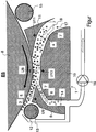
Die Figur zeigt einen Ausschnitt aus einer Entwicklerstation ES, von der nur eine rotierende Antragswalze
Benachbart der Antragswalze
Dieses Verfahren zur Trennung von elektrophoretisch mobilen Tonerpartikeln von elektrophoretisch immobilen Tonerpartikeln kann noch verbessert werden, wenn ein zusätzliches Elektrodenpaar am Einlauf
An die Separationselektrode
Zusatzlich konnen die elektrischen Potentiale U8, U10 entsprechend gewählt werden.In addition, the electrical potentials U8, U10 can be selected accordingly.
Wenn die Separationselektrode
Zusatzlich kann am Eingang des Entwicklerspalts
Wenn am Ausgang des Ableitkanals
Um eine Ablagerung von Tonerpartikeln auf den Elektroden
In der Figur sind noch zusätzliche bekannte Komponenten einer Entwicklerstation ES dargestellt. Z. B. kann vor den Einlauf in den Separator
Bei einem Ausführungsbeispiel der Vorrichtung gemaß der Figur soll z. B. die vorgegebene Ladung der Tonerpartikel positiv sein. Die elektrischen Potentiale an der Antragswalze
Die im Eingangsfluss
- – Die positiv geladenen Tonerpartikel
17 mit der vorgesehenen Mindestladung (in der Figur durch ein „+”-Zeichen gekennzeichnet) werden in Richtung des elektrischen Feldes auf dieAntragswalze 8 hin bewegt, lagern sich ander Antragswalze 8 an oder gelangen in einen ersten Bereich, der benachbart derAntragswalze 8 liegt. - – Die schwach positiv geladenen Tonerpartikel
18 (mit einer Ladung geringer als der vorgegebenen Mindestladung; in der Figur durch „o” gezeichnet) werden vom elektrischen Feld wenig beeinflusst und bewegen sich nur wenig inRichtung zur Antragswalze 8 . - – Nicht geladene Tonerpartikel
18 (in der Figur ebenfalls durch „o” gezeichnet) bleiben unbeeinflusst vom elektrischen Feld in einem Bereich, indem sieim Eingangsfluss 4 positioniert waren. - – Evtl. vorhandene negativ geladene Tonerpartikel
18 (in der Figur ebenfalls durch „o” gezeichnet) werden vom elektrischenFeld zur Gegenelektrode 10 hin abgestoßen.
- - The positively charged
toner particles 17 with the envisaged minimum charge (indicated by a "+" sign in the figure) in the direction of the electric field on the applicator roll8th moved, stored on the application roller8th or enter a first area adjacent to the applicator roll8th lies. - - The weakly positively charged toner particles
18 (with a charge less than the predetermined minimum charge, indicated by "o" in the figure) are little affected by the electric field and move only slightly towards the applicator roll8th , - - Unloaded toner particles
18 (also drawn in the figure by "o") remain unaffected by the electric field in an area by being in theinput flow 4 were positioned. - - Possibly. existing negatively charged toner particles
18 (Also drawn in the figure by "o") are from the electric field to thecounter electrode 10 repelled.
Somit verbleiben schwach positiv geladene Tonerpartikel und nicht geladene Tonerpartikel in einem zweiten Bereich benachbart der Gegenelektrode
Die Tonerpartikel dagegen, die sich auf der Antragswalze
Um einen ungehinderten Fluss der Entwicklerflüssigkeit durch die Entwicklerstation ES zu gewährleisten, ist es zweckmäßig, die Separationselektrode
Der wesentliche Vorteil der Erfindung liegt in der Verbesserung der Druckqualität. Erreicht wird dies:
- – Durch die Ableitung von Tonerpartikeln mit unzureichender oder fehlerhafter (falsch geladene Tonerpartikel) elektrophoretischer Mobilität.
- – Durch die Selektion der Tonerpartikel wird die Schicht auf der
Antragswalze 8 durch die Elektroden9 und10 gleichmäßiger kompaktiert, wodurch sich eine gleichmäßigere Schicht nach der Glättwalze12 ergibt.
- By removing toner particles with insufficient or defective (incorrectly charged toner particles) electrophoretic mobility.
- - By selecting the toner particles, the layer on the applicator roll
8th through theelectrodes 9 and10 more uniformly compacted, resulting in a more uniform layer after the smoothingroll 12 results.
BezugszeichenlisteLIST OF REFERENCE NUMBERS
- ESIT
- Entwicklerstationdeveloper station
- UU
- elektrisches Potentialelectrical potential
- 11
- Separatorseparator
- 22
- Entwicklerspaltdeveloper gap
- 33
- Entwicklerspaltdeveloper gap
- 44
- Angeförderte Entwicklerflussigkeit = EingangsflussPromoted developer flux = input flow
- 55
- Erster Teilfluss (Tonerpartikel mit ausreichender elektrophoretischer Mobilität)First partial flow (toner particles with sufficient electrophoretic mobility)
- 66
- Zweiter Teilfluss (Tonerpartikel mit ungenügender elektrophoretischer Mobilität)Second partial flow (toner particles with insufficient electrophoretic mobility)
- 77
- Elektrisch isolierendes MaterialElectrically insulating material
- 88th
- Antragswalze, z. B. EntwicklerwalzeApplication roller, z. B. developer roller
- 99
- Separationselektrodeseparation electrode
- 1010
- Gegenelektrodecounter electrode
- 1111
- Antragselektrodeapplication electrode
- 1212
- Glättwalzesmoothing roll
- 1313
- Reinigungsrakelcleaning blade
- 1414
- Ableitkanaldischarge channel
- 1515
- Reinigungswalzecleaning roller
- 1616
- Absaugeinheitsuction
- 1717
- Tonerpartikel mit der vorgesehenen MindestladungToner particles with the intended minimum charge
- 1818
- Tonerpartikel ohne die vorgesehene MindestladungToner particles without the intended minimum charge
Claims (8)
Priority Applications (3)
| Application Number | Priority Date | Filing Date | Title |
|---|---|---|---|
| DE102009060334A DE102009060334B4 (en) | 2009-12-23 | 2009-12-23 | Device for developing charge images generated on a charge image carrier in an electrophoretic pressure device |
| US12/970,481 US8509656B2 (en) | 2009-12-23 | 2010-12-16 | Device to develop charge images generated on a charge image carrier in an electrophoretic printing apparatus |
| JP2010287437A JP5679802B2 (en) | 2009-12-23 | 2010-12-24 | Apparatus and method for developing an electrostatic latent image formed on an electrostatic latent image carrier in an electrophoretic printer |
Applications Claiming Priority (1)
| Application Number | Priority Date | Filing Date | Title |
|---|---|---|---|
| DE102009060334A DE102009060334B4 (en) | 2009-12-23 | 2009-12-23 | Device for developing charge images generated on a charge image carrier in an electrophoretic pressure device |
Publications (2)
| Publication Number | Publication Date |
|---|---|
| DE102009060334A1 DE102009060334A1 (en) | 2011-06-30 |
| DE102009060334B4 true DE102009060334B4 (en) | 2012-02-16 |
Family
ID=44151320
Family Applications (1)
| Application Number | Title | Priority Date | Filing Date |
|---|---|---|---|
| DE102009060334A Expired - Fee Related DE102009060334B4 (en) | 2009-12-23 | 2009-12-23 | Device for developing charge images generated on a charge image carrier in an electrophoretic pressure device |
Country Status (3)
| Country | Link |
|---|---|
| US (1) | US8509656B2 (en) |
| JP (1) | JP5679802B2 (en) |
| DE (1) | DE102009060334B4 (en) |
Families Citing this family (31)
| Publication number | Priority date | Publication date | Assignee | Title |
|---|---|---|---|---|
| DE102012103343A1 (en) | 2012-04-17 | 2013-10-17 | Océ Printing Systems GmbH & Co. KG | A method of operating a digital printer by exposing a record carrier to ions and associated digital printers |
| DE102012103329A1 (en) | 2012-04-17 | 2013-10-17 | Océ Printing Systems GmbH & Co. KG | Digital printer has cleaning which transports removed residual liquid developer to developer roller to expose toner particles in outer flow channel, such that adhesion of toner particles at cleaning roller is loosened |
| DE102012103328A1 (en) | 2012-04-17 | 2013-10-17 | Océ Printing Systems GmbH & Co. KG | Digital printer for printing on a record carrier |
| DE102012103342A1 (en) | 2012-04-17 | 2013-10-17 | Océ Printing Systems GmbH & Co. KG | Method for operating digital printer, involves applying electrical charge having same polarity as polarity of electrical charge of toner particles of liquid developer to outer surface of back pressure roll of printing element |
| DE102012103333A1 (en) | 2012-04-17 | 2013-10-17 | Océ Printing Systems GmbH & Co. KG | Digital printer i.e. high speed printer, for printing web or sheet-shaped recording carrier, has station units interchangeable by one side plate while drive units are interchangeable by another side plate irrespective of station units |
| DE102012103336B4 (en) | 2012-04-17 | 2016-12-08 | Océ Printing Systems GmbH & Co. KG | Method for operating a digital printer and determining the toner concentration and associated digital printer |
| DE102012103340A1 (en) | 2012-04-17 | 2013-10-17 | Océ Printing Systems GmbH & Co. KG | Method for operating digital printer for printing recording medium with toner particles, involves inking intermediate image carrier with latent image by printing unit, and transferring inked image to transfer roller |
| DE102012103326B4 (en) | 2012-04-17 | 2016-11-17 | Océ Printing Systems GmbH & Co. KG | Digital printer for printing on a record carrier |
| DE102012103338B4 (en) | 2012-04-17 | 2014-05-15 | Océ Printing Systems GmbH & Co. KG | Method for operating a digital printer for printing on a recording medium and associated digital printer with mixing container |
| DE102012111041A1 (en) | 2012-11-16 | 2014-05-22 | Océ Printing Systems GmbH & Co. KG | Digital printer for printing on a record carrier |
| DE102012111791B4 (en) | 2012-12-05 | 2015-01-22 | Océ Printing Systems GmbH & Co. KG | Digital printer for printing on a record carrier |
| DE102013100843B3 (en) | 2013-01-29 | 2014-02-27 | Océ Printing Systems GmbH & Co. KG | High-speed digital printer i.e. roll-roll-printer, for printing e.g. web-like recording medium, has dosing unit providing spring unit, which exerts pressure force that is adjustable in direction of developer roller, on dosing roller |
| DE102013201549B3 (en) | 2013-01-30 | 2014-06-18 | Océ Printing Systems GmbH & Co. KG | Printing arrangement for double-sided printing of a recording medium and printing method |
| DE102013201552B4 (en) | 2013-01-30 | 2017-03-30 | Océ Printing Systems GmbH & Co. KG | Printing arrangement for double-sided printing of a recording medium and printing method |
| DE102013101446B4 (en) | 2013-02-14 | 2015-09-03 | Océ Printing Systems GmbH & Co. KG | Method for adjusting the print quality of an electrophotographic printer |
| DE102013105050B3 (en) | 2013-05-16 | 2014-07-31 | Océ Printing Systems GmbH & Co. KG | Method for adjusting tone value of print images in electrophotographic printer, involves providing dots of print image such that exposed area corresponding to image comprises total of resultant potential and deposition of toner on surface |
| DE102014114585A1 (en) | 2014-10-08 | 2016-04-14 | Océ Printing Systems GmbH & Co. KG | Method for operating a control panel for a production system and control system for a production system |
| DE102014114584A1 (en) | 2014-10-08 | 2016-04-14 | Océ Printing Systems GmbH & Co. KG | Method for operating a control panel for a production system and control system for a production system |
| DE102014114586B4 (en) | 2014-10-08 | 2020-08-20 | Canon Production Printing Germany Gmbh & Co. Kg | Method for operating a control panel for a production system and control device for a production system |
| DE102014118290A1 (en) | 2014-12-10 | 2016-06-16 | Océ Printing Systems GmbH & Co. KG | Method for configuring a control device for a production system and such a production system |
| DE102014118298B4 (en) | 2014-12-10 | 2019-12-05 | Océ Printing Systems GmbH & Co. KG | Method and apparatus for verifying the configuration of a production system |
| DE102014118293A1 (en) | 2014-12-10 | 2016-06-16 | Océ Printing Systems GmbH & Co. KG | System and method for monitoring a production system |
| DE102014118297A1 (en) | 2014-12-10 | 2016-06-16 | Océ Printing Systems GmbH & Co. KG | System for displaying control devices in a production system |
| DE102015101851B4 (en) | 2015-02-10 | 2016-10-13 | Océ Printing Systems GmbH & Co. KG | Method for adjusting the print quality of print images in an electrophoretic digital printer |
| DE102015102341A1 (en) | 2015-02-19 | 2016-08-25 | Océ Printing Systems GmbH & Co. KG | Method and device for the digital printing of a recording medium with liquid color |
| US9523946B2 (en) | 2015-02-19 | 2016-12-20 | Océ Printing Systems GmbH & Co. KG | Method and device for digital printing to a recording medium with liquid ink |
| DE102015017058A1 (en) | 2015-02-19 | 2016-08-25 | Océ Printing Systems GmbH & Co. KG | Method and device for the digital printing of a recording medium with liquid color |
| DE102015105818B4 (en) | 2015-04-16 | 2017-11-02 | Océ Printing Systems GmbH & Co. KG | A method of visually verifying a print data stream present in a print data language |
| JP6765850B2 (en) | 2015-05-27 | 2020-10-07 | キヤノン株式会社 | Separator |
| DE102015117479A1 (en) | 2015-10-14 | 2017-04-20 | Océ Printing Systems GmbH & Co. KG | Method for synchronizing control panels of a production system |
| WO2019160544A1 (en) | 2018-02-14 | 2019-08-22 | Hewlett-Packard Development Company, L.P. | Establishing distances between developer roller surfaces and electrodes |
Citations (2)
| Publication number | Priority date | Publication date | Assignee | Title |
|---|---|---|---|---|
| US5036365A (en) * | 1988-11-21 | 1991-07-30 | Benzion Landa | Field assisted filter and electrophotographic copying machine using the same |
| DE102005055156B3 (en) * | 2005-11-18 | 2007-05-31 | OCé PRINTING SYSTEMS GMBH | Apparatus and method for developing potential images formed on an intermediate image carrier in an electrographic printing or copying device |
Family Cites Families (17)
| Publication number | Priority date | Publication date | Assignee | Title |
|---|---|---|---|---|
| US3972305A (en) * | 1969-04-11 | 1976-08-03 | Xerox Corporation | Imaging system |
| US3633544A (en) * | 1969-07-03 | 1972-01-11 | Xerox Corp | Turbocloud development |
| US3782818A (en) * | 1972-11-17 | 1974-01-01 | Savin Business Machines Corp | System for reducing background developer deposition in an electrostatic copier |
| US4050806A (en) * | 1974-05-10 | 1977-09-27 | Ricoh Co., Ltd. | Method and apparatus for electrically biasing developing electrode of electrophotographic device |
| USRE31964E (en) * | 1974-06-17 | 1985-08-06 | Savin Corporation | Automatic development electrode bias control system |
| US4678317A (en) * | 1985-11-04 | 1987-07-07 | Savin Corporation | Charge and bias control system for electrophotographic copier |
| IL113235A (en) * | 1995-04-03 | 2006-07-17 | Hewlett Packard Indigo Bv | Double sided imaging |
| JPH08297417A (en) * | 1995-04-27 | 1996-11-12 | Minolta Co Ltd | Liquid developer carrying device |
| JPH08305091A (en) * | 1995-05-08 | 1996-11-22 | Minolta Co Ltd | Electrophotographic liquid developer |
| JPH0915982A (en) * | 1995-06-28 | 1997-01-17 | Minolta Co Ltd | Monitoring device for physical property of liquid |
| US5752143A (en) * | 1997-01-21 | 1998-05-12 | Xerox Corporation | Liquid immersion development apparatus having efficient charge dissipating development electrode |
| DE59702478D1 (en) | 1997-03-03 | 2000-11-16 | Oce Printing Systems Gmbh | PRINTING AND COPYING MACHINE FOR PERFORMANCE-ADJUSTED, MONOCHROME AND / OR COLORED, SINGLE OR DOUBLE-SIDED PRINTING OF A RECORDING MEDIUM |
| KR100396574B1 (en) * | 2002-01-15 | 2003-09-02 | 삼성전자주식회사 | Liquid developer imaging system |
| US7437104B2 (en) * | 2005-01-07 | 2008-10-14 | Hewlett-Packard Development Company, L.P. | Developer cleaning |
| US7356287B2 (en) * | 2005-01-10 | 2008-04-08 | Hewlett-Packard Development Company, L.P. | Ink developer foil |
| JP2006235176A (en) * | 2005-02-24 | 2006-09-07 | Konica Minolta Business Technologies Inc | Liquid development apparatus, liquid development method, and method of cleaning developing roller |
| DE102006001648B3 (en) | 2006-01-12 | 2007-09-20 | OCé PRINTING SYSTEMS GMBH | Apparatus for developing potential images of images to be printed on an intermediate image carrier with selectable custom colors in an electrographic printing or copying device |
-
2009
- 2009-12-23 DE DE102009060334A patent/DE102009060334B4/en not_active Expired - Fee Related
-
2010
- 2010-12-16 US US12/970,481 patent/US8509656B2/en not_active Expired - Fee Related
- 2010-12-24 JP JP2010287437A patent/JP5679802B2/en not_active Expired - Fee Related
Patent Citations (2)
| Publication number | Priority date | Publication date | Assignee | Title |
|---|---|---|---|---|
| US5036365A (en) * | 1988-11-21 | 1991-07-30 | Benzion Landa | Field assisted filter and electrophotographic copying machine using the same |
| DE102005055156B3 (en) * | 2005-11-18 | 2007-05-31 | OCé PRINTING SYSTEMS GMBH | Apparatus and method for developing potential images formed on an intermediate image carrier in an electrographic printing or copying device |
Also Published As
| Publication number | Publication date |
|---|---|
| DE102009060334A1 (en) | 2011-06-30 |
| JP5679802B2 (en) | 2015-03-04 |
| US20110150534A1 (en) | 2011-06-23 |
| JP2011133895A (en) | 2011-07-07 |
| US8509656B2 (en) | 2013-08-13 |
Similar Documents
| Publication | Publication Date | Title |
|---|---|---|
| DE102009060334B4 (en) | Device for developing charge images generated on a charge image carrier in an electrophoretic pressure device | |
| DE102005055156B3 (en) | Apparatus and method for developing potential images formed on an intermediate image carrier in an electrographic printing or copying device | |
| DE102010015985B4 (en) | Arrangement for cleaning a liquid developer transport means from a liquid developer layer adhering to its surface in an electrophoretic pressure apparatus | |
| DE102013201549B3 (en) | Printing arrangement for double-sided printing of a recording medium and printing method | |
| DE102012111791B4 (en) | Digital printer for printing on a record carrier | |
| DE2428734A1 (en) | LIQUID DEVELOPMENT DEVICE FOR ELECTROPHOTOGRAPHY | |
| DE3029254A1 (en) | ELECTROPHOTOGRAPHIC COPIER | |
| DE2325962C3 (en) | Electrophotographic copier working with liquid developer | |
| DE102010000549A1 (en) | Apparatus and method for developing potential images formed on an intermediate image carrier in an electrographic printing or copying device | |
| DE2803618C2 (en) | Method and device for developing electrostatic charge images | |
| DE2202673A1 (en) | Device for stripping fluids from sheet materials | |
| DE1237901B (en) | Method and device for developing charge images | |
| DE2128813A1 (en) | Developing electrophotographic latent images | |
| DE2739104C2 (en) | Device for wiping off developer liquid in an electrophotographic copier | |
| DE2528371C3 (en) | Developing device | |
| DE102004032922A1 (en) | Device and method for developing potential images previously contained on a potential image carrier containing the images to be printed in an electrographic printing or copying device | |
| EP0653077B1 (en) | Developer station for an electro-photographic printer or copier | |
| DE102012103328A1 (en) | Digital printer for printing on a record carrier | |
| DE102015110155B4 (en) | Method and device for carrying out an electrophoretic printing process and device for preparing a liquid therefor | |
| DE3118995A1 (en) | DEVICE FOR ADJUSTING THE HEIGHT OF A DEVELOPMENT MIXTURE MADE OF TONER AND CARRIER PARTICLES ON A DEVELOPER ROLLER | |
| DE2046004A1 (en) | Device for photoelectropnore tables image generation | |
| DE102012111041A1 (en) | Digital printer for printing on a record carrier | |
| DE102008018226B4 (en) | Method for determining the wear of a developer mixture used in a developer station for the development of charge images in an electrographic printing device | |
| DE2021386A1 (en) | Method and device for electrophoretic imaging | |
| DE102011081113B3 (en) | Functional element useful for electrophoretic printing system, comprises liquid developer circuit containing carrier liquid and dispersed with toner particles, where surface portion of functional element forms functional surface |
Legal Events
| Date | Code | Title | Description |
|---|---|---|---|
| R016 | Response to examination communication | ||
| R016 | Response to examination communication | ||
| R020 | Patent grant now final |
Effective date: 20120517 |
|
| R082 | Change of representative |
Representative=s name: PATENTANWAELTE SCHAUMBURG, THOENES, THURN, LAN, DE |
|
| R081 | Change of applicant/patentee |
Owner name: OCE PRINTING SYSTEMS GMBH & CO. KG, DE Free format text: FORMER OWNER: OCE PRINTING SYSTEMS GMBH, 85586 POING, DE Effective date: 20130820 |
|
| R082 | Change of representative |
Representative=s name: SCHAUMBURG UND PARTNER PATENTANWAELTE MBB, DE Effective date: 20130820 Representative=s name: SCHAUMBURG & PARTNER PATENTANWAELTE GBR, DE Effective date: 20130820 Representative=s name: SCHAUMBURG & PARTNER PATENTANWAELTE MBB, DE Effective date: 20130820 Representative=s name: PATENTANWAELTE SCHAUMBURG, THOENES, THURN, LAN, DE Effective date: 20130820 |
|
| R082 | Change of representative |
Representative=s name: SCHAUMBURG UND PARTNER PATENTANWAELTE MBB, DE Representative=s name: SCHAUMBURG & PARTNER PATENTANWAELTE GBR, DE Representative=s name: SCHAUMBURG & PARTNER PATENTANWAELTE MBB, DE |
|
| R119 | Application deemed withdrawn, or ip right lapsed, due to non-payment of renewal fee |