KR20170141069A - steel reinforcement fastening device with protective cap and tighten - Google Patents
steel reinforcement fastening device with protective cap and tighten Download PDFInfo
- Publication number
- KR20170141069A KR20170141069A KR1020160074072A KR20160074072A KR20170141069A KR 20170141069 A KR20170141069 A KR 20170141069A KR 1020160074072 A KR1020160074072 A KR 1020160074072A KR 20160074072 A KR20160074072 A KR 20160074072A KR 20170141069 A KR20170141069 A KR 20170141069A
- Authority
- KR
- South Korea
- Prior art keywords
- outer diameter
- circumferential surface
- inclined surface
- rebar
- fastened
- Prior art date
Links
Images


Classifications
-
- E—FIXED CONSTRUCTIONS
- E02—HYDRAULIC ENGINEERING; FOUNDATIONS; SOIL SHIFTING
- E02D—FOUNDATIONS; EXCAVATIONS; EMBANKMENTS; UNDERGROUND OR UNDERWATER STRUCTURES
- E02D5/00—Bulkheads, piles, or other structural elements specially adapted to foundation engineering
- E02D5/74—Means for anchoring structural elements or bulkheads
- E02D5/80—Ground anchors
-
- E—FIXED CONSTRUCTIONS
- E02—HYDRAULIC ENGINEERING; FOUNDATIONS; SOIL SHIFTING
- E02D—FOUNDATIONS; EXCAVATIONS; EMBANKMENTS; UNDERGROUND OR UNDERWATER STRUCTURES
- E02D17/00—Excavations; Bordering of excavations; Making embankments
- E02D17/20—Securing of slopes or inclines
-
- E—FIXED CONSTRUCTIONS
- E02—HYDRAULIC ENGINEERING; FOUNDATIONS; SOIL SHIFTING
- E02D—FOUNDATIONS; EXCAVATIONS; EMBANKMENTS; UNDERGROUND OR UNDERWATER STRUCTURES
- E02D2200/00—Geometrical or physical properties
- E02D2200/14—Geometrical or physical properties resilient or elastic
- E02D2200/146—Springs
-
- E—FIXED CONSTRUCTIONS
- E02—HYDRAULIC ENGINEERING; FOUNDATIONS; SOIL SHIFTING
- E02D—FOUNDATIONS; EXCAVATIONS; EMBANKMENTS; UNDERGROUND OR UNDERWATER STRUCTURES
- E02D2600/00—Miscellaneous
- E02D2600/40—Miscellaneous comprising stabilising elements
Abstract
Description
본 발명의 실시예는 비탈면(사면) 보호를 위한 보호캡과 조임구를 이용한 철근 체결장치에 관한 것으로, 보다 상세하게는 시공간편과 유지보수 간단 그리고 작업능률의 향상을 꾀할 수 있도록 한 것이고, 이로 인해 체결장치의 품질과 신뢰성을 대폭 향상시키므로 작업자들의 다양한 욕구(니즈)를 충족시켜 좋은 이미지를 심어줄 수 있도록 한 것이다.BACKGROUND OF THE INVENTION 1. Field of the Invention The present invention relates to a reinforced concrete fastening apparatus using a protective cap and a fastener for slope protection, and more particularly, to simplify construction, simplify maintenance, and improve work efficiency. This greatly improves the quality and reliability of the clamping device, so that it meets various needs (needs) of the worker and can give a good image.
주지하다시피 암반이나 비탈진 사면의 붕괴를 방지하기 위하여 체결되는 락볼트는 돌출된 형상으로 고정되어 야외에 방치된다. 이로 인하여 체결된 락볼트와 너트는 눈, 비 등에 장시간 노출되어 쉽게 산화되며 부식됨에 따라 수명이 단축되고 암반 붕괴를 방지할 수 있는 체결력 또한 저하될 뿐만 아니라 주위 자연경관과 어울리지 못하게 된다.As it is known, the rock bolt fastened to prevent the collapse of the rock slope or the sloping slope is fixed to the protruded shape and left outdoors. As a result, the rock bolts and nuts fastened to them are exposed to snow and rain for a long time and are easily oxidized and corroded, shortening the life span and deteriorating the fastening force to prevent rock collapse,
아래 종래기술로서 체결된 락볼트 및 너트의 지표면상의 노출을 방지하기 위한 커버는 국내 등록특허공보(등록번호10-0466491)에서 소개된 바 있으나, 상기의 커버는 외부에 노출된 락볼트 부위와 너트를 덮어주는 고깔형상의 단순한 덮개이며, 부식현상을 일으키는 빗물이나 눈이 덮개의 틈새로 침투하여 내부로 유입되는 것을 원천적으로 방지할 수는 없는 형태이다.A cover for preventing exposure on the ground surface of the rock bolt and nut fastened as the conventional art is disclosed in Korean Patent Registration No. 10-0466491, but the cover has a rock bolt portion exposed to the outside and a nut And it is a form that can not prevent the intrusion of rainwater or snow that may cause corrosion phenomenon into the gap and penetrate into the inside.
종래 기술로서 볼트와 너트를 체결한 후 돌출된 부위를 보호하기 위한 착탈가능한 볼트 너트캡은 국내 공개실용신안공보(공개번호 실1998-024854)에서 소개된바 있으나, 상기의 착탈가능한 볼트 너트캡은 노출된 볼트와 너트를 수용할 수 있는 볼트너트수용부를 구비한 덮개를 단순히 체결시켜 주는 형태이다. A detachable bolt nut cap for protecting a protruded portion after a bolt and a nut are fastened is disclosed in Korean Utility Model Publication No. 1998-024854. However, the detachable bolt nut cap And a cover having a bolt nut accommodating portion capable of accommodating the exposed bolt and nut is simply fastened.
보다 상세히는 노출된 볼트 및 너트와의 끼움과 탈락방지를 위하여 덮개 내부의 볼트너트수용부에 직접 탈락방지돌기를 형성하여 볼트 및 너트와 덮개를 바로 체결시킬 수 있도록 구성되어 있다. 그러나, 볼트 너트캡의 덮개부를 노출된 볼트와 너트에 직접 억지맞춤시켜 체결시켜 주는 상기의 형태는 체결과정에서 노출된 볼트산과 너트가 마모될 수 있을 뿐만 아니라 체결과정의 어려움으로 인하여 고정된 볼트와 너트가 흔들릴 수 있어 체결력의 저하를 초래할 수 있으며, 상기 볼트 너트캡과 볼트 및 너트 사이의 밀폐의 한계로 인하여 볼트 너트캡과 볼트 및 너트 틈새로 빗물이나 눈이 침투되어 내부의 볼트와 너트가 부식될 수 있다.More specifically, bolts and nuts are directly fastened to bolts and nuts by forming anti-falling protrusions directly in the bolt nut accommodating portion in the lid to prevent the bolts and nuts from being inserted and removed. However, in the above-described configuration in which the lid portion of the bolt nut cap is directly tightened to the exposed bolt and nut, the exposed bolt mount and the nut may be worn during the fastening process, Due to the limitation of the tightness between the bolt nut cap and the bolt and nut, rainwater or snow penetrates through the gap between the bolt nut cap and the bolt and nut, and the internal bolt and nut are corroded .
특히 상기 종래 기술은 수지로 보호캡을 체결시 수지가 경화되기 전에 보호캡이 이탈하는 문제점이 있고, 또한 접착력이 우수하지 못하다는 문제점 아울러 유지 보수시에 수지를 제거하기 어려운 문제점이 발생되어 전체적으로 시공이 어렵고, 유지 보수하기 어렵고 특히 작업능률이 저하되는 커다란 문제점이 발생 되었다.Particularly, when the protective cap is fastened to the resin by the resin, the protective cap detaches before the resin is cured. Further, since the resin is not easily removed during maintenance, it is difficult to remove the resin. Which is difficult to maintain, and particularly, the work efficiency is deteriorated.
상기한 문제점을 해결하기 위해 종래에는 아래와 같은 선행기술문헌들이 개발되었으나, 여전히 상기한 종래 기술들의 문제점을 일거에 해결하지 못하는 커다란 문제점이 발생 되었다.In order to solve the above-described problems, the following prior art documents have been developed in the prior art. However, there have been major problems that can not solve the problems of the conventional techniques.
본 발명은 상기와 같은 종래 기술의 제반 문제점을 해소하기 위하여 안출한 것으로, 철근과 너트, 풀림방지 및 보강철근지지구 그리고 스프링과 조임구 및 차단보호캡이 구비됨을 제1목적으로 한 것이고, 상기한 기술적 구성에 의한 본 발명의 제2목적은 비탈면(사면) 보호를 위한 보호캡과 조임구를 이용하여 철근의 체결시 시공이 간편하도록 한 것이고, 제3목적은 수지를 사용하고 보호캡을 철근에 부착 고정 시키는 방법을 배제하므로 내부 외형돌기의 나사부를 형성하여 유지보수가 간단하도록 한 것이며, 제4목적은 체결장치의 작업능률의 향상을 꾀할 수 있도록 한 것이고, 제5목적은 풀림방지 및 보강철근지지구 그리고 너트 및 철근의 부식을 방지할 수 있도록 한 것이며, 제6목적은 이로 인해 체결장치의 품질과 신뢰성을 대폭 향상시키므로 작업자들의 다양한 욕구(니즈)를 충족시켜 좋은 이미지를 심어줄 수 있도록 한 보호캡과 조임구를 이용한 철근 체결장치를 제공한다.SUMMARY OF THE INVENTION The present invention has been made in order to solve the problems of the prior art as described above, and it is a first object of the present invention to provide a reinforcing bar, a nut, an anti-loosening and reinforcing bar support, a spring, A second object of the present invention is to provide a method of manufacturing a reinforced concrete structure, which is simple in construction when a reinforcing bar is fastened using a protective cap and a fastener for protecting a slope (slope) The fourth object is to improve the working efficiency of the fastening device, and the fifth object is to prevent the fastening and reinforcement The purpose of the sixth purpose is to improve the quality and reliability of the fastening device, And a reinforcing clamping device using a protective cap and a fastening port to provide a good image by satisfying various needs of the users.
이러한 목적 달성을 위하여 본 발명은 외주면 리브에 일정 간격으로 수평마디가 돌출 형성된 철근; 철근의 외주면에 체결되며, 외주면에 외경나사돌기가 형성된 한 쌍의 풀림방지 및 보강철근지지구; 풀림방지 및 보강철근지지구의 외주면에 체결되며, 내경나사홈이 외경나사홈에 체결되도록 한 너트; 철근의 외주면에 체결되며, 상부는 좁고 하부는 넓게 외경테이퍼경사면이 형성되고, 이 경사면에 외경나사돌기가 돌출 형성된 조임구; 및 조임구의 외주면에 체결되며, 외경테이퍼경사면과 같은 경사 각도로 형성된 내경테이퍼경사면에 내경나사홈이 형성된 차단보호캡;이 포함됨을 특징으로 하는 보호캡과 조임구를 이용한 철근 체결장치를 제공한다.In order to achieve the above object, the present invention provides a reinforcing bar comprising: a reinforcing bar having a horizontal bar protruding at regular intervals on an outer circumferential rib; A pair of unblocking and rebar reinforcing bars fastened to the outer circumferential surface of the reinforcing bar and having outer diameter screw projections formed on the outer circumferential surface thereof; A nut secured to the outer peripheral surface of the reinforcement reinforcement retaining member so that the inner diameter thread groove is engaged with the outer diameter thread groove; A fastening member which is fastened to the outer peripheral surface of the reinforcing bar and has an upper portion narrowed and a lower portion formed to have an outer diameter tapered inclined surface and an outer diameter screw projection projecting from the inclined surface; And a shielding cap fastened to an outer circumferential surface of the tightening tool and having an inner diameter thread groove formed in an inner diameter tapered inclined surface formed at an oblique angle such as an outer diameter tapered inclined surface.
상기에서 상세히 살펴본 바와 같이 본 발명은 철근과 너트, 풀림방지 및 보강철근지지구 그리고 스프링과 조임구 및 차단보호캡이 구비되도록 한 것이다.As described in detail above, the present invention includes a reinforcing bar and a nut, an anti-loosening and reinforcing steel bar, and a spring, a fastener, and a barrier cap.
상기한 기술적 구성에 의한 본 발명은 비탈면(사면) 보호를 위한 보호캡과 조임구를 이용하여 철근의 체결시 시공이 간편하도록 한 것이다.The present invention according to the technical construction described above is intended to simplify the construction when fastening a reinforcing bar by using a protective cap and a fastener for protecting slopes (slopes).
또한 본 발명은 수지를 사용하고 보호캡을 철근에 부착 고정 시키는 방법을 배제하므로 내부 외형돌기의 나사부를 형성하여 유지보수가 간단하도록 한 것이다.Further, the present invention excludes a method of using a resin and fixing a protective cap to a reinforcing bar, so that a screw portion of the internal protrusion is formed to simplify maintenance.
아울러 본 발명은 체결장치의 작업능률의 향상을 꾀할 수 있도록 한 것이다.In addition, the present invention can improve the working efficiency of the fastening device.
더하여 본 발명은 풀림방지 및 보강철근지지구 그리고 너트 및 철근의 부식을 방지할 수 있도록 한 것이다.In addition, the present invention is intended to prevent corrosion of the anti-loosening and reinforcing bars and nuts and rebars.
본 발명은 상기한 효과로 인해 체결장치의 품질과 신뢰성을 대폭 향상시키므로 작업자들의 다양한 욕구(니즈)를 충족시켜 좋은 이미지를 심어줄 수 있도록 한 매우 유용한 발명인 것이다.The present invention greatly improves the quality and reliability of the fastening device due to the above-mentioned effects, and is a very useful invention that can provide a good image by satisfying various needs of workers.
이하에서는 이러한 효과 달성을 위한 본 발명의 바람직한 실시 예를 첨부된 도면에 따라 상세히 설명하면 다음과 같다.Hereinafter, preferred embodiments of the present invention will be described in detail with reference to the accompanying drawings.
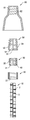
도 1 은 본 발명에 적용된 보호캡과 조임구를 이용한 철근 체결장치의 분해
사시도.
도 2 는 본 발명에 적용된 보호캡과 조임구를 이용한 철근 체결장치의 분해
단면도.
도 3 은 본 발명에 적용된 차단보호캡의 단면도.
도 4 는 본 발명에 적용된 조임구의 단면도.
도 5 는 본 발명에 적용된 풀림방지 및 보강철근지지구의 단면도.
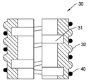
도 6 은 본 발명에 적용된 보호캡과 조임구를 이용한 철근 체결장치의 결합
상태 단면도.1 is an exploded perspective view illustrating a disassembly of a reinforcing fastening apparatus using a protective cap and a fastening port according to the present invention.
A perspective view.
Fig. 2 is an exploded perspective view showing a disassembly of a reinforcing fastening apparatus using a protective cap and a fastening port according to the present invention.
Cross-section.
3 is a cross-sectional view of a barrier protective cap applied to the present invention.
4 is a cross-sectional view of a fastener applied to the present invention.
5 is a cross-sectional view of the unblocking and reinforcing bar reinforcement applied to the present invention.
FIG. 6 is a perspective view showing a combination of a reinforcing clamping device using a protective cap and a tightening tool,
State profile.
본 발명에 적용된 보호캡과 조임구를 이용한 철근 체결장치는 도 1 내지 도 6 에 도시된 바와 같이 구성되는 것이다.The reinforcing bar fastening device using the protective cap and fastener applied to the present invention is constructed as shown in FIGS. 1 to 6.
하기에서 본 발명을 설명함에 있어, 관련된 공지 기능 또는 구성에 대한 구체적인 설명이 본 발명의 요지를 불필요하게 흐릴 수 있다고 판단되는 경우에는 그 상세한 설명은 생략할 것이다.In the following description of the present invention, detailed description of known functions and configurations incorporated herein will be omitted when it may make the subject matter of the present invention rather unclear.
그리고 후술되는 용어들은 본 발명에서의 기능을 고려하여 설정된 용어들로서 이는 생산자의 의도 또는 관례에 따라 달라질 수 있으므로 그 정의는 본 명세서 전반에 걸친 내용을 토대로 내려져야 할 것이다.It is to be understood that both the foregoing general description and the following detailed description are exemplary and explanatory and are intended to provide further explanation of the invention as claimed.
또한 도면에서 나타난 각 구성의 크기 및 두께는 설명의 편의를 위해 임의로 나타내었으므로, 본 발명이 반드시 도면에 도시된 바에 한정되지 않는다.Also, the size and thickness of each component shown in the drawings are arbitrarily shown for convenience of explanation, and the present invention is not necessarily limited to those shown in the drawings.
먼저, 본 발명은 외주면 리브(11)에 일정 간격으로 수평마디(12)가 돌출 형성된 철근(10)이 구비된다.First, according to the present invention, a reinforcing
또한 본 발명은 상기 철근(10)의 외주면에 체결되며, 외주면에 외경나사돌기(32)가 형성된 한 쌍의 풀림방지 및 보강철근지지구(30)가 구비된다.Also, the present invention is provided with a pair of anti-loosening and reinforcing bar supports 30, which are fastened to the outer circumferential surface of the reinforcing
본 발명에서는 상기 풀림방지 및 보강철근지지구(30)를 2개가 분리된 것을 도시하였으나, 이는 설명의 편의상 도시한 것이고, 필요에 따라 2개 이상의 복수개로 구성하여 사용할 수 있음은 물론이다.In the present invention, two of the release preventing and reinforcing bar supports 30 are shown as separated from each other for convenience of explanation. It is needless to say that a plurality of bars may be used.
그리고 본 발명은 상기 풀림방지 및 보강철근지지구(30)의 외주면에 체결되며, 내경나사홈(21)이 외경나사홈(32)에 체결되도록 한 너트(20)가 구비된다.The present invention further includes a
아울러 본 발명은 상기 철근(10)의 외주면에 체결되며, 상부는 좁고 하부는 넓게 외경테이퍼경사면(53)이 형성되고, 이 경사면에 외경나사돌기(54)가 돌출 형성된 조임구(50)가 구비된다.The present invention is also equipped with a tightening
더하여 본 발명은 상기 조임구(50)의 외주면에 체결되며, 외경테이퍼경사면(53)과 같은 경사 각도로 형성된 내경테이퍼경사면(61)에 내경나사홈(62)이 형성된 차단보호캡(60)이 구비된 보호캡과 조임구를 이용한 철근 체결장치를 제공한다.In addition, the present invention is characterized in that a cut-off
상기 차단보호캡(60)은 이 차단보호캡의 내부에 설치되는 다수의 부품을 보호하는 역할을 하게 된다.The
한편, 본 발명에 적용된 상기 한 쌍의 풀림방지 및 보강철근지지구(30)에는 내주면에 철근(10)의 수평마디(12)가 끼워지도록 수평마디끼움홈(31)이 형성된다.In the meantime, in the pair of the anti-loosening and
또한 본 발명에 적용된 상기 한 쌍의 풀림방지 및 보강철근지지구(30)에는 외경나사돌기(32)의 각 나사돌기 사이에 한 쌍의 풀림방지 및 보강철근지지구(30)의 이탈방지 및 유동방지를 위해 스프링(40)이 조립 설치된다.In addition, the pair of anti-loosening and reinforcing bar supports 30, which are applied to the present invention, are provided with a pair of anti-loosening and anti- The
그리고 본 발명에 적용된 상기 조임구(50)에는 내주면에 철근(10)의 리브 및 수평마디가 끼워지도록 리브끼움홈(51)과 수평마디끼움홈(52)이 형성된다.The
아울러 본 발명에 적용된 상기 조임구(50)에는 플라스틱재질의 조임구가 오무려지거나 펴지도록 작동하는 일직선 또는 경사진 절개부(55)가 형성된다.In addition, the
더하여 본 발명은 상기 조임구(50)를 최대한 긴밀히 조일 수 있도록 하기 위해 너트(20)와 상호 맞닿지 않도록 하고, 차단보호캡(60)은 긴밀히 조일 시 철판(70)과 상호 긴밀히 맞닿아 기밀을 유지시키도록 구성함이 바람직하다.In addition, the present invention prevents the
한편 본 발명은 상기의 구성부를 적용함에 있어 다양하게 변형될 수 있고 여러 가지 형태를 취할 수 있다.While the present invention has been particularly shown and described with reference to exemplary embodiments thereof, it is to be understood that the invention is not limited to the disclosed exemplary embodiments.
그리고 본 발명은 상기의 상세한 설명에서 언급되는 특별한 형태로 한정되는 것이 아닌 것으로 이해되어야 하며, 오히려 첨부된 청구범위에 의해 정의되는 본 발명의 정신과 범위 내에 있는 모든 변형물과 균등물 및 대체물을 포함하는 것으로 이해되어야 한다.It is to be understood that the invention is not to be limited to the specific forms thereof which are to be described in the foregoing description, but on the contrary, the intention is to cover all modifications, equivalents, and alternatives falling within the spirit and scope of the invention as defined by the appended claims. .
상기와 같이 구성된 본 발명 보호캡과 조임구를 이용한 철근 체결장치의 작용효과를 설명하면 다음과 같다.Hereinafter, the operation and effect of the reinforcing fastening apparatus using the protective cap and fastener according to the present invention will be described.
우선, 본 발명은 시공간편과 유지보수 간단 그리고 작업능률의 향상을 꾀할 수 있도록 한 것이다.First, the present invention can simplify construction, simplify maintenance, and improve work efficiency.
이를 위해 본 발명에 적용된 도 1 은 보호캡과 조임구를 이용한 철근 체결장치의 분해 사시도를 나타낸 것으로, 특히 조임구의 절개부를 나타내고, 풀림방지 및 보강철근지지구가 2개로 분리된 것을 도시한 것이다.FIG. 1 is an exploded perspective view of a reinforcing bar fastening apparatus using a protective cap and a fastening port, and particularly shows a cut-out portion of a fastening fastening bar, and shows two fastening and reinforcing bar retaining portions separated from each other.
그리고 도 2 는 본 발명에 적용된 보호캡과 조임구를 이용한 철근 체결장치의 분해 단면도를 타나내 것으로, 특히 내부 나사홈과 끼움홈을 도시한 것이다.FIG. 2 is an exploded cross-sectional view of a reinforcing fastening apparatus using a protective cap and a fastening port according to an embodiment of the present invention, in particular, showing internal screw grooves and fitting grooves.
또한 도 3 은 본 발명에 적용된 차단보호캡의 확대 단면도를 나타낸 것이다.3 is an enlarged cross-sectional view of a barrier protective cap applied to the present invention.
그리고 도 4 는 본 발명에 적용된 조임구의 확대 단면도를 타나낸 것이다.And Figure 4 is an enlarged cross-sectional view of a fastener applied to the present invention.
또한 도 5 는 본 발명에 적용된 풀림방지 및 보강철근지지구의 확대 단면도를 나타낸 것이다.5 is an enlarged cross-sectional view of the anti-loosening and reinforcing bar reinforcement applied to the present invention.
마지막으로 도 6 은 본 발명에 적용된 보호캡과 조임구를 이용한 철근 체결장치의 결합 상태 단면도를 나타낸 것이다.6 is a cross-sectional view of a reinforcing fastening apparatus using a protective cap and a fastener applied to the present invention.
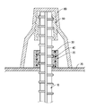
본 발명은 암반이나 경사면(사면) 공사 후 암반의 붕괴를 막고 사면을 지지하기 위하여 철근(10)이 철판(70)을 관통하여 체결된다.In the present invention, the rebar (10) penetrates through the steel plate (70) to support the slope after the rock and slope (slope) construction is prevented.
이후 본 발명은 상기 철근(10)의 외주면에는 한 쌍의 풀림방지 및 보강철근지지구(30)가 조립 설치되는 것으로, 이때 상기 풀림방지 및 보강철근지지구(30)의 외주면 즉, 외경나사돌기(32)의 각 사이에는 풀림방지 및 보강철근지지구(30)의 이탈방지 및 유동방지를 위해 스프링(40)이 조립 설치되는 것이다.In the present invention, a pair of loosening preventing and reinforcing
이때 본 발명에 적용된 상기 스프링(40)은 자체 텐션력을 갖고 있기 때문에절토면의 지지판이 지면에서 이격 등을 방지함과 아울러 풀림방지 및 보강철근지지구(30)의 상호 약간의 유격 움직임을 돕는 동시에 풀림방지 및 보강철근지지구(30)의 이탈방지 및 유동방지 그리고 덜렁거림을 방지하게 된다.At this time, since the
이어서 본 발명에 적용된 상기 풀림방지 및 보강철근지지구(30)의 외주면에는 너트(20)가 체결되는 것으로, 이 너트(20)의 내경나사홈(21)은 풀림방지 및 보강철근지지구(30)의 외주면에 형성된 외경나사돌기(32)에 체결된다.The
이후 본 발명에 적용된 상기 철근(10)의 외주면 선단에는 조임구(50)가 조립 설치된다.Then, a
이때 상기 조임구(50)의 내주면에 형성된 리브끼움홈(51)에는 철근(10)의 리브(11)가 끼워지고, 수평마디끼움홈(52)에는 철근(10)의 수평마디(12)가 각각 끼워지게 된다.The
상기한 상태에서 본 발명은 상기 조임구(50)의 외주면에 차단보호캡(60)을 조립 설치한다.In the above-described state of the present invention, the shielding
이때 상기 차단보호캡(60)의 내주면에 형성된 내경나사홈(62)에는 조임구(50)의 외주면에 돌출된 외경나사돌기(54)가 조립 설치된다.At this time, an outer
특히 본 발명은 조임구(50)의 외경테이퍼경사면(53)과 차단보호캡(60)의 내경테이퍼경사면(61)이 상호 상부는 좁고 하부는 넓게 형성되어 차단보호캡(60)을 조이게 되면 안쪽으로 밀려들어가게 되는 동시에 조임구(50)에 형성된 절개부(55)는 상호 좁혀지면서 조임구(50)가 철근(10)에 긴밀히 밀착되어 결과적으로 차단보호캡(60)과 조임구(50) 그리고 철근(10)이 상호 긴밀한 체결력을 유지하게 되며 탄성을 가진 소재를 사용함으로 인해 풀림을 방지하게 된다.The outer diameter taper inclined
즉, 본 발명은 철근(10)은 그대로 있는 상태에서 차단보호캡(60)을 회전시키게 되면 내경나사홈(62)이 외경나사돌기(54)를 따라 회전하여 차단보호캡(60)이 앞으로 전진 이동하게 되고, 따라서 차단보호캡(60)의 전진 이동에 의해 조임구(50)는 좁혀지게 되는 것이고, 이 과정에서 내경테이퍼경사면(61)은 외경테이퍼경사면(53)을 따라 이동하여 결과적으로 차단보호캡(60) 및 조임구(50)가 철근(10)에 긴밀히 조여질 수 있도록 하게 된다.That is, according to the present invention, when the
아울러 본 발명은 상기 조임구(50)를 최대한 긴밀히 조일 수 있도록 하기 위해 너트(20) 또는 풀림방지 및 보강철근지지구(30)와 상호 맞닿지 않도록 하고, 차단보호캡(60)은 긴밀히 조일 시 철판(70)과 상호 긴밀히 맞닿아 기밀을 유지시키도록 함이 바람직하다.In addition, in order to tighten the
본 발명 보호캡과 조임구를 이용한 철근 체결장치의 기술적 사상은 실제로 동일결과를 반복 실시 가능한 것으로, 특히 이와 같은 본원발명을 실시함으로써 기술발전을 촉진하여 산업발전에 이바지할 수 있어 보호할 가치가 충분히 있다.The technical idea of the reinforcing fastening apparatus using the protective cap and fastener of the present invention is that the same result can be repeatedly practically practiced. In particular, by implementing the present invention as described above, it is possible to contribute to industrial development by promoting technological development, have.
<도면의 주요 부분에 대한 부호의 설명>
10: 철근
20: 너트
30: 풀림방지 및 보강철근지지구
40: 스프링
50: 조임구
60: 차단보호캡Description of the Related Art
10: Rebar
20: Nut
30: Anti-loosening and rebar
40: spring
50: Fastener
60: Blocking protection cap
Claims (6)
풀림방지 및 보강철근지지구의 외주면에 체결되며, 내경나사홈이 외경나사홈에 체결되도록 한 너트;
철근의 외주면에 체결되며, 상부는 좁고 하부는 넓게 외경테이퍼경사면이 형성되고, 이 경사면에 외경나사돌기가 돌출 형성된 조임구; 및
조임구의 외주면에 체결되며, 외경테이퍼경사면과 같은 경사 각도로 형성된 내경테이퍼경사면에 내경나사홈이 형성된 차단보호캡;이 포함됨을 특징으로 하는 보호캡과 조임구를 이용한 철근 체결장치.
A pair of unblocking and rebar reinforcing bars fastened to the outer circumferential surface of the reinforcing bar and having outer diameter screw projections formed on the outer circumferential surface thereof;
A nut secured to the outer peripheral surface of the reinforcement reinforcement retaining member so that the inner diameter thread groove is engaged with the outer diameter thread groove;
A fastening member which is fastened to the outer peripheral surface of the reinforcing bar and has an upper portion narrowed and a lower portion formed to have an outer diameter tapered inclined surface and an outer diameter screw projection projecting from the inclined surface; And
And a shielding cap fastened to an outer circumferential surface of the fastener and having an inner diameter thread groove formed in an inner diameter tapered inclined surface formed at an oblique angle such as an outer diameter tapered inclined surface.
상기 한 쌍의 풀림방지 및 보강철근지지구에는,
내주면에 철근의 수평마디가 끼워지도록 수평마디끼움홈;이 더 포함됨을 특징으로 하는 보호캡과 조임구를 이용한 철근 체결장치.
The method according to claim 1,
In the pair of the anti-loosening and rebar reinforcing bars,
And a horizontal fitting groove is formed on the inner circumferential surface so that the horizontal bar of the reinforcing bar is inserted into the inner circumferential surface of the reinforcing bar.
상기 한 쌍의 풀림방지 및 보강철근지지구에는,
외경나사돌기의 각 나사돌기 사이에 한 쌍의 풀림방지 및 보강철근지지구의 이탈방지 및 유동방지를 위해 스프링;이 더 포함됨을 특징으로 하는 보호캡과 조임구를 이용한 철근 체결장치.
The method according to claim 1 or 2,
In the pair of the anti-loosening and rebar reinforcing bars,
And a spring for preventing a pair of loosening prevention and a prevention of breakage of the reinforcement reinforcement and preventing the movement of the reinforcement reinforcement between the screw projections of the outer diameter screw projections.
상기 조임구에는,
내주면에 철근의 리브 및 수평마디가 끼워지도록 리브끼움홈과 수평마디끼움홈;이 더 포함됨을 특징으로 하는 보호캡과 조임구를 이용한 철근 체결장치.
The method according to claim 1,
In the fastening port,
Wherein the ribs and the horizontal joints are inserted into the ribs and the horizontal joints so that the ribs and the horizontal joints of the reinforcing bars are inserted into the inner peripheral surface of the reinforcing bars.
상기 조임구에는,
플라스틱재질의 조임구가 오무려지거나 펴지도록 작동하는 일직선 또는 경사진 절개부;가 더 포함됨을 특징으로 하는 보호캡과 조임구를 이용한 철근 체결장치.
The method according to claim 1 or 4,
In the fastening port,
The apparatus of claim 1, further comprising a straight or sloped incision cutter which is operated to open or close the plastic fastener.
상기 조임구를 최대한 긴밀히 조일 수 있도록 하기 위해 너트와 상호 맞닿지 않도록 하고, 차단보호캡은 긴밀히 조일 시 철판과 상호 긴밀히 맞닿아 기밀을 유지시키도록 구성함을 특징으로 하는 보호캡과 조임구를 이용한 철근 체결장치.The method according to claim 1,
Wherein the tightening cap is tightly fitted to the steel plate so as to closely contact the steel plate to maintain the airtightness so that the tightening hole can be tightened as tightly as possible. Rebar tightening device.
Priority Applications (1)
| Application Number | Priority Date | Filing Date | Title |
|---|---|---|---|
| KR1020160074072A KR101890918B1 (en) | 2016-06-14 | 2016-06-14 | steel reinforcement fastening device with protective cap and tighten |
Applications Claiming Priority (1)
| Application Number | Priority Date | Filing Date | Title |
|---|---|---|---|
| KR1020160074072A KR101890918B1 (en) | 2016-06-14 | 2016-06-14 | steel reinforcement fastening device with protective cap and tighten |
Publications (2)
| Publication Number | Publication Date |
|---|---|
| KR20170141069A true KR20170141069A (en) | 2017-12-22 |
| KR101890918B1 KR101890918B1 (en) | 2018-08-22 |
Family
ID=60936445
Family Applications (1)
| Application Number | Title | Priority Date | Filing Date |
|---|---|---|---|
| KR1020160074072A KR101890918B1 (en) | 2016-06-14 | 2016-06-14 | steel reinforcement fastening device with protective cap and tighten |
Country Status (1)
| Country | Link |
|---|---|
| KR (1) | KR101890918B1 (en) |
Cited By (2)
| Publication number | Priority date | Publication date | Assignee | Title |
|---|---|---|---|---|
| WO2023215327A1 (en) * | 2022-05-03 | 2023-11-09 | Zenobia International Investments Inc. | Radiator cap safety cover |
| WO2023215324A1 (en) * | 2022-05-03 | 2023-11-09 | Zenobia International Investments Inc | Safety radiator cap cover with valve releaser |
Citations (7)
| Publication number | Priority date | Publication date | Assignee | Title |
|---|---|---|---|---|
| KR100466491B1 (en) | 2001-11-30 | 2005-01-15 | 심석래 | Rock bolt linking reinforcement equipment |
| KR100638645B1 (en) | 2005-11-04 | 2006-10-31 | 심석래 | A rock anchor for multistage grouting |
| KR100712476B1 (en) | 2005-11-04 | 2007-04-27 | 심석래 | A rock anchor for multistage grouting |
| KR101112052B1 (en) | 2009-02-24 | 2012-03-13 | 심석래 | Connected equipmentes for reinforcing rock bolt |
| KR101317332B1 (en) | 2011-03-22 | 2013-10-11 | 심석래 | A protective cap for bolt and nut having connection component and sealing part |
| KR101370954B1 (en) * | 2013-04-04 | 2014-03-10 | (주) 효창이엔지 | Site surface pressure reinforced structure and method associated soil nailing |
| KR101378793B1 (en) * | 2013-10-22 | 2014-03-27 | 김정태 | Retaining wall system for planting and the construction method |
-
2016
- 2016-06-14 KR KR1020160074072A patent/KR101890918B1/en active IP Right Grant
Patent Citations (7)
| Publication number | Priority date | Publication date | Assignee | Title |
|---|---|---|---|---|
| KR100466491B1 (en) | 2001-11-30 | 2005-01-15 | 심석래 | Rock bolt linking reinforcement equipment |
| KR100638645B1 (en) | 2005-11-04 | 2006-10-31 | 심석래 | A rock anchor for multistage grouting |
| KR100712476B1 (en) | 2005-11-04 | 2007-04-27 | 심석래 | A rock anchor for multistage grouting |
| KR101112052B1 (en) | 2009-02-24 | 2012-03-13 | 심석래 | Connected equipmentes for reinforcing rock bolt |
| KR101317332B1 (en) | 2011-03-22 | 2013-10-11 | 심석래 | A protective cap for bolt and nut having connection component and sealing part |
| KR101370954B1 (en) * | 2013-04-04 | 2014-03-10 | (주) 효창이엔지 | Site surface pressure reinforced structure and method associated soil nailing |
| KR101378793B1 (en) * | 2013-10-22 | 2014-03-27 | 김정태 | Retaining wall system for planting and the construction method |
Cited By (2)
| Publication number | Priority date | Publication date | Assignee | Title |
|---|---|---|---|---|
| WO2023215327A1 (en) * | 2022-05-03 | 2023-11-09 | Zenobia International Investments Inc. | Radiator cap safety cover |
| WO2023215324A1 (en) * | 2022-05-03 | 2023-11-09 | Zenobia International Investments Inc | Safety radiator cap cover with valve releaser |
Also Published As
| Publication number | Publication date |
|---|---|
| KR101890918B1 (en) | 2018-08-22 |
Similar Documents
| Publication | Publication Date | Title |
|---|---|---|
| KR101890918B1 (en) | steel reinforcement fastening device with protective cap and tighten | |
| KR101317332B1 (en) | A protective cap for bolt and nut having connection component and sealing part | |
| KR20180102343A (en) | Double thread bolt and double combination nut | |
| JPH10252278A (en) | Level adjusting fitting for column base and sill | |
| JP5366593B2 (en) | Drain plug and water drain treatment method using this drain plug | |
| JP6773308B2 (en) | Waterproof door structure | |
| JP2000179053A (en) | Connecting metal | |
| KR102089552B1 (en) | A bolt assembly | |
| JP2018096531A (en) | Lock nut structure fastened into bolt | |
| KR200428458Y1 (en) | Anchorbolt protection cap | |
| JP4815520B2 (en) | Fixing hardware, slope stabilization structure and slope stabilization method using the same | |
| KR102060876B1 (en) | Loose stopper bolt and plate | |
| US20080304933A1 (en) | Bolt holding member | |
| JP2001162549A (en) | Wrench | |
| JP2009108546A (en) | Nut for rockbolt | |
| JP3604225B2 (en) | Temporary fixing device for steel plate for building structure reinforcement | |
| KR200478182Y1 (en) | Screw | |
| JP7451054B2 (en) | One-touch lock bolt | |
| KR101688187B1 (en) | Long square head bolt assembling for panels of assembly type water tank | |
| JP5877453B2 (en) | Housing for underground structures | |
| KR200375123Y1 (en) | Concrete matrix interval regulation structure | |
| KR20000034764A (en) | Reinforced manhole having double cover | |
| JP3144051U (en) | Locking special nut | |
| KR200345022Y1 (en) | a bolt cover for a fixed mold | |
| JP2005351062A (en) | Protective cap device for lock bolt for fixing cover receiving frame of manhole |
Legal Events
| Date | Code | Title | Description |
|---|---|---|---|
| A201 | Request for examination | ||
| E902 | Notification of reason for refusal | ||
| AMND | Amendment | ||
| E601 | Decision to refuse application | ||
| AMND | Amendment | ||
| X701 | Decision to grant (after re-examination) | ||
| GRNT | Written decision to grant |