KR20170140497A - Mold device using high-frequency induction heating - Google Patents
Mold device using high-frequency induction heating Download PDFInfo
- Publication number
- KR20170140497A KR20170140497A KR1020160072857A KR20160072857A KR20170140497A KR 20170140497 A KR20170140497 A KR 20170140497A KR 1020160072857 A KR1020160072857 A KR 1020160072857A KR 20160072857 A KR20160072857 A KR 20160072857A KR 20170140497 A KR20170140497 A KR 20170140497A
- Authority
- KR
- South Korea
- Prior art keywords
- core
- cooling
- cavity
- heat
- heating
- Prior art date
Links
Images


Classifications
-
- B—PERFORMING OPERATIONS; TRANSPORTING
- B29—WORKING OF PLASTICS; WORKING OF SUBSTANCES IN A PLASTIC STATE IN GENERAL
- B29C—SHAPING OR JOINING OF PLASTICS; SHAPING OF MATERIAL IN A PLASTIC STATE, NOT OTHERWISE PROVIDED FOR; AFTER-TREATMENT OF THE SHAPED PRODUCTS, e.g. REPAIRING
- B29C33/00—Moulds or cores; Details thereof or accessories therefor
- B29C33/02—Moulds or cores; Details thereof or accessories therefor with incorporated heating or cooling means
- B29C33/06—Moulds or cores; Details thereof or accessories therefor with incorporated heating or cooling means using radiation, e.g. electro-magnetic waves, induction heating
-
- B—PERFORMING OPERATIONS; TRANSPORTING
- B29—WORKING OF PLASTICS; WORKING OF SUBSTANCES IN A PLASTIC STATE IN GENERAL
- B29C—SHAPING OR JOINING OF PLASTICS; SHAPING OF MATERIAL IN A PLASTIC STATE, NOT OTHERWISE PROVIDED FOR; AFTER-TREATMENT OF THE SHAPED PRODUCTS, e.g. REPAIRING
- B29C33/00—Moulds or cores; Details thereof or accessories therefor
- B29C33/76—Cores
-
- B—PERFORMING OPERATIONS; TRANSPORTING
- B29—WORKING OF PLASTICS; WORKING OF SUBSTANCES IN A PLASTIC STATE IN GENERAL
- B29C—SHAPING OR JOINING OF PLASTICS; SHAPING OF MATERIAL IN A PLASTIC STATE, NOT OTHERWISE PROVIDED FOR; AFTER-TREATMENT OF THE SHAPED PRODUCTS, e.g. REPAIRING
- B29C45/00—Injection moulding, i.e. forcing the required volume of moulding material through a nozzle into a closed mould; Apparatus therefor
- B29C45/17—Component parts, details or accessories; Auxiliary operations
- B29C45/72—Heating or cooling
- B29C45/73—Heating or cooling of the mould
Abstract
Description
본 발명은 급속가열 및 급속냉각 금형장치에 관한 것으로서, 더욱 상세하게는 <1> 고주파유도가열을 이용하여 국부The present invention relates to a rapid heating and rapid cooling mold apparatus, and more particularly, to a rapid heating and rapid cooling mold apparatus using <1>
적으로 급속가열과 급속냉각을 단시간내에 절환 실시할 수 있도록 하여 성형품의 품질을 대폭 높이면서 안정된Rapid heating and rapid cooling can be performed within a short period of time, thereby significantly improving the quality of the molded article,
열정 성형조건의 조성을 가능하게 하는 급속가열 및 급속냉각 금형장치에 관한 것이다.To a rapid heating and rapid cooling mold apparatus capable of forming passive molding conditions.
일반적으로 사출 금형은 코어를 내장하는 상형판과 하형판이 상호 형합되어 성형하고자 하는 제품의 형상과 동In general, the injection mold is formed by interlacing the upper and lower mold plates with the core,
일한 캐비티가 형성되도록 하고, 이 캐비티에 고체화(입자, 펠릿)되어 있는 용융된 수지를 고압으로 주입하여And a molten resin solidified (particles, pellets) is injected into the cavity at a high pressure
제품을 성형한다. 이러한 사출금형은 성형을 하는데 있어 여러 성형 조건이 요구되는데, 그 중 수지의 온도를Mold the product. Injection molds require various molding conditions for molding, in which the temperature of the resin
설정해야 하며, 그런 다음 금형의 캐비티 내부로 수지가 적정한 사출 압력과 속도로서 주입되도록 설정해야 한And then set the resin into the cavity of the mold to inject at the proper injection pressure and speed
다.All.
<3> 한편, 주지된 바와 같이, 플라스틱 재질의 제품을 사출성형 과정에서 동일한 성형품임에도 불구하고 색상차이가≪ 3 > Meanwhile, as is well known, although plastic products are the same in the injection molding process,
선명하게 나타나거나 미세한 선이 형성되는 것과 같은 웰드라인이 발생하게 된다.A weld line such as a sharp appearance or a fine line is formed.
<4> 일예로, LCD 패널 등에 채용되는 도광판이나 광디스크 등과 같이 두께가 얇은 박판의 성형품들은 수지의 유동<4> For example, thin plate thin plates such as a light guide plate and an optical disk, which are used in LCD panels and the like,
특성에 따라 생산 수율이 결정되는데, 이러한 수지의 유동특성이 불량하게 되면, 금형의 캐비티내에 용융 수지The yield of production is determined according to the characteristics. When the flow characteristics of such resin become poor, the molten resin
가 골고루 퍼지는데 있어 시간차가 발생하게 되고 이는 결과적으로 상기 캐비티내에 충진된 수지가 부분적으로A time difference is generated in uniformly spreading the resin. As a result, the resin filled in the cavity is partially
불균일하게 응고되는 현상을 야기하여 웰드라인과 미성형을 발생시키게 되는 것이다. 이러한 웰드라인 또는 미Causing a phenomenon of non-uniformly solidifying, resulting in weld lines and unformed. These weld lines or
성형은 외관상 좋지 않을 뿐만 아니라 성형품의 강도가 저하되는 등의 단점으로 인해 고급 성형품의 경우에는The molding is not only bad in appearance but also has a disadvantage in that the strength of the molded article is lowered,
불량품으로 처리하고 있는 실정이다.And it is treated as a defective product.
상기와 같이 웰드라인 또는 미성형을 최소화하기 위해서는 상기 수지 유동특성에 <5> 영향을 미치는 요소를 개선해As described above, in order to minimize the weld line or non-molding, it is necessary to improve the factors affecting the resin flow characteristics
야 하는데, 이때 상기 수지 유동특성에 영향을 미치는 요소로는 사출압력과 사출속도 그리고 낮은 점성의 수지At this time, factors influencing the resin flow characteristics include injection pressure and injection speed, and low viscosity resin
를 사용하는 것이나 현실적으로 적용이 어려운 문제점이 있다.Which is difficult to apply in practice.
<6> 이러한 문제점을 개선하고자 종래에는 금형을 유리전이 온도 이상으로 가열하여 수지의 고화를 완화시킴으로써In order to solve this problem, conventionally, by heating the mold to a temperature higher than the glass transition temperature to alleviate solidification of the resin
유동특성을 양호하게 할 수 있도록 금형에 히터를 설치하거나 또는 화염이나 고온의 가스를 직접 분사하는 방법A heater may be installed in the mold so as to improve flow characteristics, or a method of directly spraying a flame or a high temperature gas
이 제안되었다.Lt; / RTI >
<7> 그러나, 상기 히터를 설치하는 방법은 금형의 캐비티에 대한 균일한 가열조건을 설계 및 적용하기가 대단히 어However, in the method of installing the heater, it is very difficult to design and apply a uniform heating condition to the cavity of the mold
려운 문제점이 있으며, 상기 화염이나 고온의 가스를 직접 분사하는 경우에는 그을음 등을 유발하여 초정밀 성And when the flame or high-temperature gas is injected directly, it causes soot and the like,
형품의 경우 성형품의 오염 원인이 되는 문제점이 있다.In the case of molded articles, there is a problem that the articles are contaminated.
<8> 또한, 상기 히터를 설치하거나 또는 화염이나 가스를 분사하는 방법은 금형의 가열과 냉각에 소요되는 시간이The method of installing the heater or spraying a flame or a gas is not limited to the time required for heating and cooling the mold
상대적으로 길어지는 것에 의해 생산성이 크게 떨어질 뿐만 아니라 입열량의 정확한 제어와 추정이 곤란하여 도As a result, the productivity is greatly lowered and it is difficult to precisely control and estimate the heat input amount
광판이나 광디스크와 같은 정밀 성형품이 성형에는 적합하지 않는 단점이 있다.There is a disadvantage in that precision molded articles such as optical disks and optical disks are not suitable for molding.
본 발명은 상기와 같은 종래 기술의 문제점을 해결하기 위하여 창출된 것으로서, 본 발명은 고주파 유도가열을SUMMARY OF THE INVENTION The present invention has been made in order to solve the above problems of the prior art,
이용하여 금형에 국부적으로 짧은 시간에 가열을 실시하고 냉각수단을 통해 급속냉각을 가능하게 하여 상기 금The metal mold is locally heated for a short time, and rapid cooling is enabled through the cooling means,
형의 캐비티 내의 수지 유동특성을 양호하게 하면서 생산성을 높일 수 있도록 한 급속가열 및 급속냉각 금형장Rapid heating and rapid cooling molds capable of improving productivity while improving resin flow characteristics in a mold cavity
치를 제공하는데 그 목적이 있다.The purpose is to provide value.
상기의 목적을 실현하기 위한 본 발명의 일 실시예에 따른 급속가열 및 급속냉각 금형장치는, 노즐로부터 용융In order to accomplish the above object, the rapid heating and rapid cooling mold apparatus according to an embodiment of the present invention includes:
된 수지를 공급받는 캐비티가 형성된 성형 코어를 갖는 금형장치에 있어서, 상기 성형 코어는 상기 캐비티의 반And a molding core having a cavity for receiving the resin, wherein the molding core has a half of the cavity
대면에 대응되는 면적에 국부 가열을 하는 것으로 코일홈을 따라 워크 코일이 권선되어 이루어진 발열By locally heating the area corresponding to the facing surface, heat generated by winding the work coil along the coil groove
코어부와, 상기 워크 코일에 선택적으로 유도전류를 인가하여 발열 코어부를 발열시키는 고주파 발진기와, 상기A high frequency oscillator which generates heat by selectively applying an induction current to the work coil,
성형 코어의 내부에 형성되어 냉각수가 순환되는 냉각채널을 포함하여 구성되는 것을 그 특징으로 한다.And a cooling channel formed inside the molded core to circulate the cooling water.
<11> 본 발명의 바람직한 한 특징으로서, 상기 발열 코어부는 일측 외면으로 알루미늄 또는 구리 계열의 열전도성 금According to a preferred aspect of the present invention, the heat generating core portion is made of aluminum or a copper-based thermally conductive gold
속재로 된 열평형판이 부착 구비되고, 이 열평형판은 그 내부에 냉각수가 순환되는 냉각채널이 형성된 것에 있The heat plate is provided with a cooling channel in which cooling water is circulated.
다.All.
<12> 본 발명의 바람직한 다른 특징으로서, 상기 성형 코어는 일측에 알루미늄 또는 구리계열의 열전도성 금속재로As another preferred feature of the present invention, the molded core is formed of an aluminum or copper-based thermally conductive metal material on one side
된 열평형관이 매립 또는 끼움구조에 의해 구비되는 것에 있다.Wherein the heat-equalizing pipe is provided by a buried or fitting structure.
<13> 본 발명의 다른 실시예에 따른 급속가열 및 급속냉각 금형장치는, 노즐로부터 용융된 수지를 공급받는 캐비티가According to another aspect of the present invention, there is provided a rapid heating and rapid cooling mold apparatus comprising a cavity for receiving molten resin from a nozzle,
형성된 성형 코어를 갖는 금형장치에 있어서, 상기 성형 코어는 상기 캐비티의 반대면에 대응되는 면적에 국부A mold apparatus having a formed core, wherein the molded core has an area corresponding to the opposite surface of the cavity,
가열을 하는 것으로 워크 코일이 권선된 발열 코어와, 상기 워크 코일에 선택적으로 유도전류를 인가하여 발열A heat generating core in which a work coil is wound by heating, and a heating coil
코어를 발열시키는 고주파 발진기와, 상기 성형 코어의 내부에 형성되어 냉각수가 순환되는 냉각채널을 포함하A high frequency oscillator for generating heat of the core, and a cooling channel formed inside the molding core for circulating cooling water
여 구성되는 것을 그 특징으로 한다.Which is characterized in that it is constituted.
<14> 본 발명의 바람직한 한 특징으로서, 상기 발열 코어는 일측면에 알루미늄 또는 구리계열의 열전도성 금속재로In a preferred aspect of the present invention, the heat generating core is made of an aluminum or copper-based thermally conductive metal material
된 열평형판이 부착 구비되는 것에 있다.And the heat plate is attached.
<15> 본 발명의 바람직한 다른 특징으로서, 상기 열평형판은 그 내부에 냉각수가 순환되는 냉각채널이 형성된 것에In another preferred aspect of the present invention, the thermal equilibrium plate has a cooling channel in which cooling water is circulated,
있다.have.
<16> 본 발명의 바람직한 또 다른 특징으로서, 상기 성형 코어는 일측에 알루미늄 또는 구리계열의 열전도성 금속재According to still another preferred aspect of the present invention, the molded core is made of aluminum or a copper-based thermally conductive metal material
로 된 열평형관이 매립 또는 끼움구조에 의해 구비되는 것에 있다.Is provided by an embedding or fitting structure.
본 발명의 바람직한 또 다른 특징으로서, 상기 발열 코어는 적어도 2개 이상으로 구비되고 하나의 워크 코일로In another preferred aspect of the present invention, the heat generating core comprises at least two heat cores,
권선되는 것에 있다.It is in being coiled.
<18> 본 발명의 또 다른 실시예에 따른 급속가열 및 급속냉각 금형장치는, 노즐로부터 용융된 수지를 공급받는 캐비티가 형성된 성형 코어를 갖는 금형장치에 있어서, 상기 성형 코어는 상기 캐비티의 반대면에 부착되어 캐비티According to another embodiment of the present invention, there is provided a rapid heating and rapid cooling mold apparatus having a molding core in which a cavity for receiving molten resin from a nozzle is formed, wherein the molding core has an opposite surface And the cavity
에 대응되는 면적에 대한 국부가열을 하는 것으로 단일의 코일을 평면상으로 연속적으로 굽힘 성형하여 된 워크By performing local heating with respect to an area corresponding to the workpiece W, a single coil is continuously bent in a plane,
코일 시트와, 상기 워크 코일시트에 선택적으로 유도전류를 인가하여 발열 코어를 발열시키는 고주파 발진기와,A high frequency oscillator which generates heat by selectively applying an induction current to the work coil sheet,
상기 성형 코어의 내부에 형성되어 냉각수가 순환되는 냉각채널을 포함하여 구성되는 것을 그 특징으로 한다.And a cooling channel formed inside the molded core to circulate the cooling water.
본 발명의 또 다른 실시예에 따른 급속가열 및 급속냉각 금형장치는, 노즐로부터 <19> 용융된 수지를 공급받는 캐비According to another embodiment of the present invention, there is provided a rapid heating and rapid cooling mold apparatus, comprising: a cuvette
티가 형성된 성형 코어를 갖는 금형장치에 있어서, 상기 성형 코어는 상기 캐비티의 반대면에 부착되어 캐비티A mold apparatus having a molded core formed with a tee, wherein the molding core is attached to an opposite surface of the cavity,
에 대응되는 면적에 대한 국부가열을 하는 것으로 평면상에 소용돌이 모양으로 가공되는 코일 설치홈과, 상기A coil mounting groove formed in a plane on a plane by performing local heating with respect to an area corresponding to the area
코일 설치홈에 끼움 구비되는 것으로 코일을 연속적으로 굽힘 성형하여 된 워크 코일체와, 상기 성형 코어의 내A work coil integral with the coil mounting groove and formed by continuously bending a coil;
부에 형성되어 냉각수가 순환되는 냉각채널를 포함하여 구성되는 것을 그 특징으로 한다.And a cooling channel which is formed in the cooling passage and through which the cooling water is circulated.
<20> 본 발명의 바람직한 한 특징으로서, 상기 워크 코일체는 일측면에 알루미늄 또는 구리계열의 열전도성 금속재로<20> In a preferred aspect of the present invention, the work coils are made of an aluminum or copper-based thermally conductive metal material
된 열평형판이 부착 구비되고, 이 열평형판의 내부에는 냉각수가 순환되는 냉각채널이 형성된 것에 있다.And a cooling channel through which cooling water is circulated is formed in the inside of the thermal equilibrium plate.
<21> 본 발명의 바람직한 한 특징으로서, 상기 성형 코어는 일측에 알루미늄 또는 구리계열의 열전도성 금속재로 된In a preferred aspect of the present invention, the molded core is made of a thermally conductive metal material of aluminum or copper series on one side
열평형관이 매립 또는 끼움구조에 의해 구비되는 것에 있다.And a thermal equilibrium tube is provided by an embedding or fitting structure.
<22> 본 발명의 특징 및 이점들은 첨부도면에 의거한 다음의 상세한 설명으로 더욱 명백해질 것이다. 이에 앞서 본The features and advantages of the present invention will become more apparent from the following detailed description based on the attached drawings. Prior to this,
명세서 및 청구범위에 사용된 용어나 단어는 통상적이고 사전적인 의미로 해석되어서는 아니 되며, 발명자가 그The terms and words used in the specification and claims should not be construed in a conventional and dictionary sense,
자신의 발명을 가장 최선의 방법으로 설명하기 위해 용어의 개념을 적절하게 정의할 수 있다는 원칙에 입각하여Based on the principle that the concept of a term can be properly defined to describe its invention in the best way possible
본 발명의 기술적 사상에 부합되는 의미와 개념으로 해석되어야만 한다.And should be construed in light of the meanings and concepts consistent with the technical idea of the present invention.
본 발명에 따른 급속가열 및 급속냉각 금형장치는, 고주파 유도가열을 이용하여 금형의 캐비티에 대한 순간 가In the rapid heating and rapid cooling mold apparatus according to the present invention, by using high frequency induction heating, a moment about the cavity of the mold
열이 가능하여 수지의 유동특성이 대단히 양호하게 할 수 있을 뿐만 아니라 금형의 캐비티에 대한 국부 표면을It is possible to make the resin flow characteristics very good, and the local surface to the cavity of the mold
순간적으로 가열하기 때문에 냉각에 소요되는 시간도 종전의 히터 또는 화염이나 고온가스 방식에 비하여 크게Since the heating is instantaneous, the time required for cooling is significantly larger than that of the conventional heater or flame or high temperature gas system
단축시킬 수 있게 된다..
<24> 또한, 열전달 특성이 우수하면서 경제적인 구리 또는 알루미늄 계열의 금속재로 된 열평형판을 부가 구성하는In addition, a thermally balanced plate made of a copper or aluminum-based metal material having an excellent heat transfer characteristic and being economical is additionally constituted
구조를 통해 금형의 캐비티 부분에 대한 균일한 급속가열을 가능하게 하는 것은 물론이고 효율적인 냉각채널의Structure to enable uniform rapid heating of the cavity portion of the mold, as well as an efficient cooling channel
구성을 통해 급속한 냉각을 실현시킬 수 있으므로 결과적으로 고품질의 성형품을 빠른 시간내에 양산할 수 있어The rapid cooling can be realized through the constitution, and as a result, a high-quality molded article can be mass-produced in a short time
산업상 대단히 유용한 효과를 제공한다.It provides a very useful effect in industry.
도 1은 본 발명의 제1실시예에 따른 급속가열 및 급속냉각 금형장치의 구성을 개략적으로 나타낸 단면도,
<105> 도 2는 도 1의 급속가열 및 급속냉각 금형장치의 분해 단면도,
<106> 도 3은 도 2의 ″A-A″선을 나타낸 단면도,
<107> 도 4는 본 발명의 제2실시예에 따른 급속가열 및 급속냉각 금형장치의 구성을 개략적으로 나타낸 단면도,
<108> 도 5는 도 4의 ″B-B″방향에서 바라본 요부 구성을 나탄낸 도면,
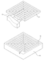
<109> 도 6은 도 4의 급속가열 및 급속냉각 금형장치의 요부 구성을 나타낸 사시도,
<110> 도 7은 도 4의 변형된 다른 실시예를 나타낸 단면도,
<111> 도 8은 본 발명의 제3실시예에 따른 급속가열 및 급속냉각 금형장치의 구성을 개략적으로 나타낸 단면도,
<112> 도 9는 도 8에 적용되는 유도가열 코일시트를 나타낸 평면도,
<113> 도 10은 본 발명의 제4실시예에 따른 급속가열 및 급속냉각 금형장치의 구성을 개략적으로 나타낸 단면도,
<114> 도 11은 도 10의 ″C-C″ 방향에서 바라본 요부 구성을 나타낸 사시도,1 is a sectional view schematically showing the structure of a rapid heating and rapid cooling mold apparatus according to a first embodiment of the present invention,
FIG. 2 is an exploded cross-sectional view of the rapid heating and rapid cooling mold apparatus of FIG. 1,
FIG. 3 is a sectional view showing the line "AA" in FIG. 2,
FIG. 4 is a cross-sectional view schematically showing the structure of a rapid heating and rapid cooling mold apparatus according to a second embodiment of the present invention. FIG.
FIG. 5 is a view showing a recessed configuration viewed from the direction of "BB" in FIG. 4,
FIG. 6 is a perspective view showing the essential structure of the rapid heating and rapid cooling mold apparatus of FIG. 4;
FIG. 7 is a sectional view showing another modified embodiment of FIG. 4,
8 is a cross-sectional view schematically showing a configuration of a rapid heating and rapid cooling mold apparatus according to a third embodiment of the present invention,
FIG. 9 is a plan view of the induction heating coil sheet applied to FIG. 8,
10 is a cross-sectional view schematically showing the structure of a rapid heating and rapid cooling mold apparatus according to a fourth embodiment of the present invention. FIG.
FIG. 11 is a perspective view showing the configuration of a recess viewed from the direction of "CC" in FIG. 10;
이하, 첨부된 도면을 참조하여 본 발명에 따른 급속가열 및 급속냉각 금형장치를 설명하면 다음과 같다.Hereinafter, a rapid heating and rapid cooling mold apparatus according to the present invention will be described with reference to the accompanying drawings.
<26> 먼저, 도면들 중 동일한 구성요소 또는 부품들은 가능한 동일한 참조부호로 나타내고 있음을 유의하여야 한다.First, it should be noted that the same components or parts among the drawings are denoted by the same reference numerals as possible.
본 발명을 설명함에 있어 관련된 공지의 기능 혹은 구성에 대한 구체적인 설명은 본 발명의 요지를 모호하지 않In the following description of the present invention, a detailed description of known functions and configurations incorporated herein will be omitted when it may make the subject matter of the present invention rather unclear.
게 하기 위하여 생략한다.It is omitted for the sake of simplicity.
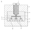
<27> 도 1은 본 발명의 제1실시예에 따른 급속가열 및 급속냉각 금형장치의 구성을 개략적으로 나타낸 단면도이고,1 is a cross-sectional view schematically showing the structure of a rapid heating and rapid cooling mold apparatus according to a first embodiment of the present invention,
도 2는 도 1의 급속가열 및 급속냉각 금형장치의 분해 단면도이며, 도 3은 도 2의 ″A-A″선을 나타낸 단면도이Fig. 2 is an exploded cross-sectional view of the rapid heating and rapid cooling mold apparatus of Fig. 1, and Fig. 3 is a cross-sectional view of " A-
다.All.
<28> 도면에서 보는 바와 같이 금형장치(1)는 성형 코어(3c.4c)를 내장하는 상형판(3)과 하형판(4)으로 대별되고, 이As shown in the figure, the
들 상형판(3)과 하형판(4)은 선택적으로 형합 및 분리되는 것에 의해 상기 성형 코어(3c.4c)에 용융 수지를 주The
입할 수 있도록 하거나 또는 주입된 수지가 고화된 성형품을 취출할 수 있도록 이루어진다. 이와 같은 구성은So that the injected resin can take out the solidified molded article. Such a configuration
공지의 금형장치와 대동소이하므로 상세한 설명은 생략한다.And thus the detailed description thereof will be omitted.
<29> 다만, 본 발명은 상기 성형 코어(3c.4c)에 형성된 캐비티(c)에 대하여 유도가열을 통한 급속가열을 실시하여 상However, the present invention is characterized in that the cavity (c) formed in the molded core (3c.4c) is rapidly heated by induction heating,
기 캐비티(c)에 주입된 수지의 유동특성을 양호하게 하여 웰드라인이나 미성형을 방지하고, 아울러 열전달 특성The flow characteristics of the resin injected into the cavity (c) are improved to prevent the weld line and the unformed, and the heat transfer characteristic
이 우수한 금속재를 개재시키고 적절한 냉각채널을 배치하는 구성을 통해 급속냉각을 실시하여 생산 수율성을Rapid cooling is carried out through the arrangement of the superior metal material and the arrangement of the appropriate cooling channels,
높일 수 있도록 하는 것을 특징이 있다.So that it can be increased.
<30> 도 1 내지 도 3을 참조하여 본 발명의 제1실시예에 따른 금형장치의 구성을 살펴보면 다음과 같다.1 to 3, a mold apparatus according to a first embodiment of the present invention will now be described.
<31> 먼저, 금형장치(1)는 앞서 설명한 바와 같이, 상형판(3)과 하형판(4)으로 구성되고, 이들 상형판(3)과 하형판(4)은 상호 대향하는 방향으로 각각의 성형 코어(3c.4c)가 구비되는 구조로서, 여기서, 상기 성형 코어(3c.4c)First, as described above, the
는 서로 형합되는 것에 성형하고자 하는 제품의 형상과 동일한 형상의 공간으로 된 캐비티(c)가 형성되어 있으A cavity c having a shape identical to the shape of the product to be molded is formed in the cavity
며, 이때의 상기 캐비티(c)는 상기 상형판(3)의 일측에 연결된 노즐(7)로부터 수지를 공급받도록 구성된다.The cavity (c) is configured to receive resin supplied from a nozzle (7) connected to one side of the upper plate (3).
한편, 상기 성형 코어(3c.4c) 중 적어도 어느 하나 또는 둘 모두는 상기 캐비티(<32> c)의 반대면에 대응되는 면적에On the other hand, at least one or both of the molded
대하여 국부 가열을 실시할 수 있도록 코일홈(11)을 따라 워크 코일(25)이 권선된 발열 코어부(20)가 제공되며,There is provided a
상기 캐비티(c)에 대한 급속냉각을 실시하도록 냉각채널(13)이 형성된다. 또한, 급속가열과 급속냉각의 효율성A cooling channel (13) is formed to effect rapid cooling of the cavity (c). In addition, the efficiency of rapid heating and rapid cooling
을 높이기 위하여 열전달 특성이 우수한 구리 또는 알루미늄 계열의 금속재로 된 열평형판(40)이 부가The
설치된다.Respectively.
<33> 이하, 본 발명의 제1실시예에 따른 주요 구성 요소를 살펴본다.Hereinafter, main components according to the first embodiment of the present invention will be described.
<34> 상기 코일홈(11)은 상기 성형 코어(4c)에서 캐비티(c)의 반대측면에 소정의 깊이로서 가공되며, 도면에서 보는The
바와 같이 중심부에 발열 코어부(20)가 구비되게 형성된다.The heat
<35> 이러한 코일홈(11)은 상기 캐비티(c)에 근접한 깊이로 형성되는 것이 바람직하며, 공지의 밀링머신 등을 이용하It is preferable that the
여 가공될 수 있을 것이다.It can be processed.
<36> 상기 워크 코일(25)은 가열대상 즉, 발열 코어부(20)의 주위에 일회전 또는 다회전 권선되는 것으로 후술할 고The
주파 발진기(30)로부터 변환되는 전기적 에너지에 의해 발열 코어부(20)의 온도를 올리게 된다. 이러한 워크 코The temperature of the heat generating
일(25)은 동관이 사용될 수 있으며 이외에도 공지의 다양한 유도코일이 사용되어도 무방하므로 상세한 설명은A copper pipe may be used as the
생략한다.It is omitted.
<37> 상기 발열 코어부(20)는 도면에서 보는 바와 같이 외주부에 코일홈(11)이 형성되는 것에 의해 관형상으로 구비As shown in the drawing, the heat generating
되며, 상기 코일홈(11)을 따라 권선된 워크 코일(25)에 흐르는 전류에 의해 와전류 손실과 히스테리시스And currents flowing in the work coils 25 wound along the
(Hysteresis) 손실(磁性體의 경우)의 저항(抵抗)에 의하여 열(熱)이 발생한다. 이렇게 발생된 열에 의해 상기Hysteresis Heat (heat) is generated by the resistance (resistance) of the loss (in the case of the magnetic body). By the generated heat,
발열 코어부(20)를 구비한 성형 코어가 국부적으로 가열된다.The molded core having the
한편, 상기 발열 코어부(20)는 상기 성형 코어에 하나 또는 소정의 간격을 두고 복수개 구비될 수 있으며, 이는A plurality of the heat generating
캐비티(c)의 형상이나 면적 그리고 후술할 고주파 발진기(30)의 효율을 감안하여 적절하게 설계될 수 있을 것이The shape and the area of the cavity c and the efficiency of the high-
다.All.
<39> 상기 고주파 발진기(30)는 상기 워크 코일(25)에 선택적으로 유도전류를 인가하여 상기 발열 코어부(20)가 고주The high-
파 가열에 의해 발열되도록 하는 요소이다.It is an element that causes heat to be generated by wave heating.
<40> 여기서, 상기 고주파가열(高周波加熱)은 정확하게는 고주파유도가열이라 칭하는 것으로 전자유도(電磁誘導) 작Here, the high-frequency heating (high-frequency heating) is precisely referred to as high-frequency induction heating,
용에 의한 것으로 교류(고주파) 전류가 흐르는 코일속에 위치하는 금속 도전체 즉, 본 발명의 발열 코어부(20)A metal conductor located in a coil through which an alternating current (high frequency) current flows, that is, the heat generating
는 와전류 손실과 히스테리시스(Hysteresis) 손실(磁性體의 경우)의 저항 (抵抗)에 의하여 열(熱)이 발생하게(Heat) is generated by the resistance (resistance) of the eddy current loss and the hysteresis loss (in the case of the magnetic body)
된다. 이러한 고주파 발진기(30)는 입력전압을 이용하여 제어회로를 구동시키고 그 제어회로가 입력전원을 고주do. This high-
파로 단속(chopper)하여 그 단속전압을 인버터 변압기(고주파 변압기)에 전달하는 것에 의해 원하는 출력을 얻Chopper and transferring the intermittent voltage to an inverter transformer (high frequency transformer) to obtain a desired output
는 장치로서, 순간적으로 국부를 가열하므로 에너지의 효율화와 설비 비용이 경제적이며, 접촉전극을 필요로 하Is an apparatus that instantaneously heats a local part, so that energy efficiency and facility cost are economical, and a contact electrode is required
지 않아 운전이 극히 안정되고 고장 발생 빈도가 낮으며 부품 교환이 용이하다. 이러한 고주파 발진기(30)는 공Operation is extremely stable, fault frequency is low, and parts are easy to replace. The high-frequency oscillator (30)
지의 다양한 고주파 발진기가 사용되거나 또는 고주파 발생 인버터가 사용되어도 무방하므로 상세한 설명은 생A variety of high-frequency oscillators may be used, or high-frequency generators may be used.
략한다..
<41> 냉각채널(13)은 상기 성형 코어(4c)의 내부에 냉각수가 순환될 수 있게 냉각홀을 가공하여 된 것으로서, 도시하The cooling
지는 않았으나 외부로부터 냉각수를 공급받도록 구성된다. 이러한 냉각채널(13)은 상기 고주파 발진기(30)의 동But is supplied with cooling water from the outside. The cooling
작시에는 냉각수가 순환되지 않으며, 이와 반대로 상기 고주파 발진기(30)의 가동이 중단된 상태에서는 냉각수Cooling water is not circulated when the high-
가 공급 순환된다.Is supplied and circulated.
<42> 한편, 본 발명에서는 상기 성형 코어(4c)에만 냉각채널(13)을 형성한 구조를 도시하였으나, 본 발명은 이에 한In the present invention, a cooling
정하지 않고 상기 상형판(3)에 구비된 성형 코어(3c)에도 냉각채널이 형성되어도 무방할 것이다.The cooling channel may be formed in the formed
열평형판(40)은 상기 발열 코어부(20)의 가열시 그 열을 캐비티(c)의 표면으로 균일하게 전달할 수 있도록 하여The
상기 캐비티(c)내의 수지유동 특성을 최적의 조건을 조성하기 위한 것으로서, 상기 발열 코어부(20)의 일측면The heat
즉, 도면을 기준으로 살펴보면 상기 발열 코어부(20)의 하면측에 부착 구비된다.That is, when viewed from the drawing, it is attached to the lower face side of the heat generating
<44> 이러한, 상기 열평형판(40)은 열전도성이 대단히 우수한 금속재로 사용되며, 본 발명에서는 경제적이면서 가공이 용이한 구리 또는 알루미늄 계열의 금속재의 사용을 제안한다.The
한편, 상기 열평형판(40)은 도면에서 보는 바와 같이 상기 성형 코어(4c)에 <45> 형성된 냉각채널(13)과 마찬가지로Meanwhile, as shown in the drawing, the
외부로부터 냉각수를 공급받아 그 내부에서 순환되도록 한 냉각채널(43)이 마련되며, 이러한 냉각채널(43)을 통A cooling
해 급속냉각이 가능하게 된다.So that rapid cooling is possible.
<46> 즉, 상기 열평형판(40)은 상기 고주파 발진기(30)를 통한 발열 코어부(20)의 가열시 그 열을 캐비티(c)의 표면That is, the
으로 빠른 시간내에 균일하게 전달하여 상기 캐비티(c)의 표면 온도가 균일하게 가열 될 수 있게 할 뿐만 아니So that the surface temperature of the cavity (c) can be uniformly heated
라 냉각수를 이용한 냉각시에는 상기 캐비티(c)의 표면 온도를 빠른 시간내에 균일하게 냉각시키게 된다.The surface temperature of the cavity (c) is uniformly cooled in a short period of time during cooling using the cooling water.
<47> 이러한 열평형판(40)은 상기 캐비티(c)의 온도 환경을 균일하게 하는 것은 물론이고 급가열·급냉각 효율을 높The
이는 역할을 한다.It plays a role.
<48> 한편, 상기 성형 코어(4c)는 도시하지는 않았으나 냉각채널(13)과 위치 간섭되지 않게 홀 또는 홈을 가공하여Meanwhile, although not shown, the formed
길이재의 열평형관을 구비시켜 성형 코어(4c)의 전체적인 열분포도를 균일하게 할 수 있을 것이다.A longitudinal thermal equilibrium pipe may be provided so that the overall thermal distribution of the molded
<49> 또한, 상기 캐비티(c)에 용융된 수지를 공급하는 노즐(7) 역시 그 외주면에 유도코일인 워크 코일이 감겨지는The
것에 의해 발열되도록 구성될 수 있을 것이다.The heat generated by the heat source may be generated.
<50> 상기와 같이 구성되는 제 1실시예에 따른 급속가열 및 급속냉각 금형장치의 작용을 설명하면 다음과 같다.The operation of the rapid heating and rapid cooling mold apparatus according to the first embodiment will now be described.
<51> 금형장치(1)를 구성하는 상형판(3)과 하형판(4)이 형합되어 성형 코어(3c)와 성형 코어(4c)가 서로 밀폐된 캐비The
티(c)를 형성한 상태에서, 상기 상형판(3)의 일측에 연결된 노즐(7)로부터 캐비티(c) 내로 용융 수지가 주입됨The molten resin is injected into the cavity c from the
과 동시에 상기 고주파 발진기(30)를 가동시킨다.And simultaneously operates the high-frequency oscillator (30).
<52> 이어서, 상기 고주파 발진기(30)로부터 고주파 전류를 인가받는 워크 코일(25)은 그 중심에 위치한 발열 코어부Then, the
(20)를 발열시키고, 상기 발열 코어부(20)를 일체로 구비한 성형 코어(4c)가 열을 전도받아 가열된다. 여기서,And the molded
상기 발열 코어부(20)는 상기 금형장치(1)의 캐비티(c) 면적에 대응하여 설치되어 있으므로 상기 캐비티(c)의Since the heat generating
표면에 대한 국부 가열을 실시하게 된다.And a local heating is performed on the surface.
한편, 상기 발열 코어부(20)의 일측에 구비되는 열평형판(40)은 열전도 특성이 대단히 우수한 구리 또는 알루미On the other hand, the thermal
늄 계열의 금속재로 제공됨에 따라 상기 발열 코어부(20)와의 접촉에 의해 전체적으로 균일한 온도로서 가열되And is heated to a uniform temperature as a whole by contact with the heat generating
는 것에 의해 결과적으로 상기 캐비티(c)의 표면에 대한 온도분포를 균일하게 조성하게 된다.As a result, the temperature distribution on the surface of the cavity (c) is uniformly formed.
<54> 상기 캐비티(c)내에 수지의 주입이 완료되면, 상기 고주파 발진기(30)의 가동이 중단됨과 동시에 상기 성형 코When injection of the resin into the cavity (c) is completed, the operation of the high frequency oscillator (30) is stopped, and at the same time,
어에 형성된 냉각채널(13)과, 상기 열평형판(40)에 형성된 냉각채널(43)에 냉각수를 공급 순환시키면, 상기 냉When the cooling water is circulated through the cooling
각채널(13,43)을 순환하는 냉각수에 의해 성형 코어가 급속하게 냉각됨에 따라 수지의 고화속도를 높일 수 있게As the formed core is rapidly cooled by the cooling water circulating through each of the
된다.do.
<55> 따라서, 상기 고주파 유도가열을 이용하여 금형장치(1)의 국부 즉, 캐비티(c)의 표면에 대한 국부 가열을 순간Therefore, by using the high-frequency induction heating, local heating of the local portion of the
적으로 실시하여 상기 캐비티(c)내의 수지 유동특성을 양호하게 조성함과 동시에 냉각시에는 성형 코어 및 열평(C). In addition, at the time of cooling, the molded core and the thermocycles
형판에 형성된 냉각채널(13,43)에 냉각수를 순환공급시키는 구성을 통해 급속한 냉각을 실시하여 상기 캐비티The cooling water is circulated and supplied to the
(c)내의 수지 고화속도를 단축시켜 생산성을 높일 수 있다.the resin solidification rate in the step (c) can be shortened and the productivity can be increased.
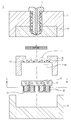
<56> 도 4는 본 발명의 제2실시예에 따른 급속가열 및 급속냉각 금형장치의 구성을 개략적으로 나타낸 단면도이고,FIG. 4 is a cross-sectional view schematically showing the structure of a rapid heating and rapid cooling mold apparatus according to a second embodiment of the present invention,
도 5는 도 4의 ″B-B″방향에서 바라본 요부 구성을 나탄낸 도면이며, 도 6은 도 4의 급속가열 및 급속냉각 금Fig. 5 is a view showing a recessed configuration viewed from the direction of " B-B " in Fig. 4. Fig. 6 is a cross-
형장치의 요부 구성을 나타낸 사시도이다. 그리고, 도 7은 도 4의 변형된 다른 실시예를 나타낸 단면도이다.Type device according to the present invention. 7 is a cross-sectional view showing another modified embodiment of FIG.
<57> 본 실시예에서의 금형장치(1)는 전술한 제1실시예에서와 마찬가지로 상형판(3)과 하형판(4)으로 구성되고, 이들The
상형판(3)과 하형판(4)은 상호 대향하는 방향으로 각각의 성형 코어(3c.4c)가 구비되는 구조로서, 여기서, 상기The
성형 코어(3c.4c)는 서로 형합되는 것에 성형하고자 하는 제품의 형상과 동일한 형상의 공간으로 된 캐비티(c)The formed
가 형성되어 있으며, 이때의 상기 캐비티(c)는 상기 상형판(3)의 일측에 연결된 노즐(7)로부터 수지를 공급받도(C) is supplied with resin from the nozzle (7) connected to one side of the upper plate (3), and the cavity
록 구성되며, 이러한 구성은 공지의 기술에 의해 실시되는 것이므로 상세한 설명은 생략한다.And this configuration is implemented by a known technique, and thus a detailed description thereof will be omitted.
다만, 본 실시예에서의 금형장치(1)는 상기 성형 코어(3c.4c)중 적어도 어느 하나 또는 둘 모두는 상기 캐비티However, in the
(c)의 반대면에 대응되는 면적에 대하여 국부 가열을 실시할 수 있도록 발열 코어(21)가 부착 구성되며, 상기(21) is attached so that local heating can be applied to the area corresponding to the opposite surface of the heat-generating core (c)
발열 코어(21)에 외주면에 감겨진 워크 코일(25)에 고주파 전류를 인가하는 고주파 발진기(30)가 구성된다. 또A high-frequency oscillator (30) for applying a high-frequency current to the work coil (25) wound on the outer peripheral surface of the heat generating core (21) is constituted. In addition
한 상기 성형 코어(3c,4c)의 내부에는 냉각수가 순환될 수 있게 냉각채널(13)이 형성되고, 상기 발열 코어(21)A cooling channel (13) is formed inside the formed cores (3c, 4c) so that cooling water can be circulated. The cooling core (13)
의 일측면에는 열전도성이 우수한 금속재로 된 열평형판(40)이 부착 구비된다.A
상기 발열 코어(21) 도면에서 보는 바와 같이 외주면에 워크 코일(25)이 일회전 <59> 또는 여러 회전 감길 수 있도록As shown in the drawing of the
소정의 길이를 갖는 관형상의 부재로서, 별도로 제작되어 상기 성형 코어 중 어느 하나 또는 양측 모두에 장착A tubular member having a predetermined length, which is separately manufactured and attached to either or both of the molded cores
될 수 있으며, 도면에서 보는 바와 같이 성형 코어(4c)의 일측 즉, 캐비티(c)의 반대면측에 캐비티(c)을 수용할And as shown in the figure, the cavity c is accommodated on one side of the molded
수 있을 정도의 면적을 갖는 장착홈(mh)을 형성하고, 이 장착홈(mh)내에 끼움구조로 구비시키거나 또는 후술할It is possible to form the mounting groove mh having an area enough to allow the mounting groove mh to be fitted in the mounting groove mh,
열평형판(40)과 함께 용접으로 구비시킬 수 있을 것이다.It may be provided by welding together with the
<60> 이러한 발열 코어(21)는 외주면에 나선형의 홈을 형성하여 후술할 워크 코일(25)이 감겨지는 구성이며, 발열면The
적의 크기에 따라 하나 또는 적어도 2개 이상으로 구비될 수 있으며, 복수개 구비되는 경우에는 하나의 워크 코One or at least two or more of them may be provided depending on the size of the enemy,
일(25)로 권선되는 것이 바람직하다.It is preferable that the winding is performed at the
<61> 이러한 발열 코어(21)는 외주면에 권선된 워크 코일(25)에 흐르는 전류에 의해 와전류 손실과 히스테리시스The
(Hysteresis) 손실(磁性體의 경우)의 저항(抵抗)에 의하여 열(熱)이 발생하게 되고, 이렇게 발생된 열에 의해(Heat) is generated by the resistance (resistance) of the hysteresis loss (in the case of the magnetic body), and by the generated heat
상기 발열 코어(21)를 구비한 성형 코어(4c)가 국부적으로 가열된다.The molded
<62> 한편, 상기 발열 코어(21)는 상기 성형 코어에 하나 또는 소정의 간격을 두고 복수개 구비될 수 있으며, 도면에The
서 보는 바와 같이 볼트와 같은 나사부재를 이용하여 후술할 열평형판(40)에 마운팅될 수 있도록 구비되거나 또And may be mounted on a thermal
는 도시하지는 않았으나 용접이나 끼움구조를 통해 구비될 수 있을 것이다. 이러한 구성의 상기 발열 코어(21)May be provided through a welding or fitting structure, though not shown. The heat-generating
는 캐비티(c)의 형상이나 면적 그리고 후술할 고주파 발진기(30)의 효율을 감안하여 그 크기나 형태, 위치, 개Considering the shape and the area of the cavity (c) and the efficiency of the high-frequency oscillator (30) to be described later,
수 등이 설계시 고려되어야 할 것이다.And so on should be considered in design.
<63> 상기 워크 코일(25)은 가열대상 즉, 발열 코어부(20)의 주위에 일회전 또는 다회전 권선되는 것으로 후술할 고The
주파 발진기(30)로부터 변환되는 전기적 에너지에 의해 발열 코어(21)의 온도를 올리게 된다. 이러한 워크 코일The temperature of the
(25)은 동관이 사용될 수 있으며 이외에도 공지의 다양한 유도코일이 사용되어도 무방하므로 상세한 설명은 생(25) may be a copper tube, or a variety of known induction coils may be used.
략한다..
<64> 상기 고주파 발진기(30)는 상기 워크 코일(25)에 선택적으로 유도전류를 인가하여 상기 발열 코어부(20)가 고주The
파 가열에 의해 발열되도록 하는 요소로서, 전술한 제1실시예와 대동소이하다.This is an element that causes heat to be generated by wave heating, and is similar to the first embodiment described above.
즉, 상기 고주파가열(高周波加熱)은 정확하게는 고주파유도가열이라 칭하는 것으로 전자유도(電磁誘導) 작용에That is, the high-frequency heating (high-frequency heating) is precisely referred to as high-frequency induction heating,
의한 것으로 교류(고주파) 전류가 흐르는 코일속에 위치하는 금속 도전체 즉, 본 발명의 발열 코어부(20)는 와A metal conductor located in a coil through which an alternating current (high frequency) current flows, that is, the heat generating
전류 손실과 히스테리시스(Hysteresis) 손실(磁性體의 경우)의 저항 (抵抗)에 의하여 열(熱)이 발생하게 된다.Heat is generated by resistance (resistance) of current loss and hysteresis loss (in the case of a magnetic body).
이러한 고주파 발진기(30)는 입력전압을 이용하여 제어회로를 구동시키고 그 제어회로가 입력전원을 고주파로The high-
단속(chopper)하여 그 단속전압을 인버터 변압기(고주파 변압기)에 전달하는 것에 의해 원하는 출력을 얻는 장(Chopper) to transfer the intermittent voltage to an inverter transformer (high-frequency transformer)
치로서, 순간적으로 국부를 가열하므로 에너지의 효율화와 설비 비용이 경제적이며, 접촉전극을 필요로 하지 않Since the local heating is instantaneously performed, the energy efficiency and the facility cost are economical, and the contact electrode is not required
아 운전이 극히 안정되고 고장 발생 빈도가 낮으며 부품 교환이 용이하다. 이러한 고주파 발진기(30)는 공지의Operation is extremely stable, fault frequency is low, and parts are easy to replace. The high-frequency oscillator (30)
다양한 고주파 발진기가 사용되거나 또는 고주파 발생 인버터가 사용되어도 무방하므로 상세한 설명은A variety of high-frequency oscillators may be used or high-frequency generators may be used.
생략한다.It is omitted.
<66> 냉각채널(13)은 상기 성형 코어(4c)의 내부에 냉각수가 순환될 수 있게 냉각홀을 가공하여 된 것으로서, 도시하The cooling
지는 않았으나 외부로부터 냉각수를 공급받도록 구성된다. 이러한 냉각채널(13)은 상기 고주파 발진기(30)의 동But is supplied with cooling water from the outside. The cooling
작시에는 냉각수가 순환되지 않으며, 이와 반대로 상기 고주파 발진기(30)의 가동이 중단된 상태에서는 냉각수Cooling water is not circulated when the high-
가 공급 순환된다.Is supplied and circulated.
<67> 한편, 본 발명에서는 상기 성형 코어(4c)에만 냉각채널(13)을 형성한 구조를 도시하였으나, 본 발명은 이에 한In the present invention, a cooling
정하지 않고 상기 상형판(3)에 구비된 성형 코어(3c)에도 냉각채널이 형성되어도 무방할 것이다.The cooling channel may be formed in the formed
<68> 열평형판(40)은 상기 발열 코어(21)의 일측면에 부착되어 열을 전도받아 균일한 발열을 실시하여 상기 캐비티The
(c)의 열적환경을 안정화시키거나 또는 내부에 형성된 냉각채널(43)을 순환하는 냉각수에 의해 균일한 냉각을(c), or by uniform cooling by cooling water circulating in the cooling
빠른 시간내에 실시할 수 있는 구성요소로서, 열전도성이 대단히 우수한 금속재로 사용되며 바람직하게는 경제As a component that can be carried out quickly, it is used as a metal material with excellent thermal conductivity,
적이면서도 가공이 용이한 구리 또는 알루미늄 계열의 금속재가 사용된다.A copper or aluminum-based metal material that is easy to process and is used is used.
<69> 이러한, 열평형판(40)은 도면에서 보는 바와 같이, 상기 발열 코어(21)의 상면과 상기 성형 코어(4c)의 하면 사As shown in the figure, the
이에 구비되는 구성이며, 그 상·하면이 발열 코어(21)와 성형 코어(4c)에 접촉되는 열전달 매질의 역할을The upper and lower surfaces serve as a heat transfer medium in contact with the
한다.do.
즉, 상기 열평형판(40)은 상기 발열 코어(21)를 통해 열을 전달받으면, 그 열전도성 금속재가 갖는 고유의 특성That is, when the heat-balanced
에 의해 전체가 균일하게 가열된다. 이와 같이 열평형판(40)이 균일하게 가열되는 것에 의해 그 일측면에 접촉된 성형 코어(4c) 역시 균일하게 가열됨에 따라 상기 캐비티(c)의 표면의 온도차를 최소화시킬 수 있게 된다.The whole is uniformly heated. As the
한편, 상기 열평형판(40)은 도면에서 보는 바와 같이 상기 성형 코어(4c)에 <71> 형성된 냉각채널(13)과 마찬가지로Meanwhile, as shown in the figure, the
외부로부터 냉각수를 공급받아 그 내부에서 순환되도록 한 냉각채널(43)이 형성하는 것에 의해 급속냉각을 가능The cooling water is supplied from the outside to be circulated in the cooling
하게 한다. 이때의 상기 열평형판(40)의 냉각채널(43)을 통과하는 냉각수에 의해 상기 캐비티(c)는 단시간내에. At this time, by the cooling water passing through the cooling channel (43) of the thermal equilibrium plate (40), the cavity (c)
급속냉각이 이루어진다.Rapid cooling is achieved.
<72> 즉, 상기 열평형판(40)은 상기 고주파 발진기(30)를 통한 발열 코어(21)의 가열시 그 열을 캐비티(c)의 표면으That is, the
로 빠른 시간내에 균일하게 전달하여 상기 캐비티(c)의 표면 온도가 균일하게 가열 될 수 있게 할 뿐만 아니라So that the surface temperature of the cavity (c) can be uniformly heated
냉각채널(43)을 순환하는 냉각수를 이용한 냉각시에는 상기 캐비티(c)의 표면 온도를 빠른 시간내에 균일하게When cooling is performed using the cooling water circulating through the cooling
냉각시키게 된다.And cooled.
<73> 이러한 열평형판(40)은 상기 캐비티(c)의 온도 환경을 균일하게 하는 것은 물론이고 급가열·급냉각 효율을 높The
이는 역할을 한다.It plays a role.
<74> 한편, 도 7에서 보는 바와 같이, 상기 성형 코어(4c)는 냉각채널(13)과 위치 간섭되지 않게 홀 또는 홈을 가공7, the molded
하여 길이재의 열평형관(45)을 구비시켜 성형 코어(4c)의 전체적인 온도 평형을 도모할 수 있을 것이다.A longitudinal
<75> 또한, 본 발명에서는 하형판(4)의 성형 코어(4c)에만 상기 발열 코어(21)와 열평형판(40) 그리고 열평형관(45)In the present invention, the
을 구비한 구조를 예시하였으나, 본 발명은 이에 한정하지 않고 성형 코어(3c)에도 동일하게 적용하여도 무방할However, the present invention is not limited to this, and it is also possible to apply the same to the molded
것이다.will be.
<76> 상기와 같이 구성되는 제 2실시예에 따른 급속가열 및 급속냉각 금형장치의 작용을 설명하면 다음과 같다.Hereinafter, the operation of the rapid heating and rapid cooling mold apparatus according to the second embodiment will be described.
<77> 금형장치(1)를 구성하는 상형판(3)과 하형판(4)이 형합되어 성형 코어(3c)와 성형 코어(4c)가 서로 밀폐된 캐비The
티(c)를 형성한 상태에서, 상기 상형판(3)의 일측에 연결된 노즐(7)로부터 캐비티(c) 내로 용융 수지가 주입되The molten resin is injected into the cavity c from the
면, 상기 금형장치(1)는 고주파 발진기(30)를 가동시킨다.The
<78> 이어서, 상기 고주파 발진기(30)로부터 고주파 전류를 인가받는 워크 코일(25)은 그 중심에 위치한 발열 코어Then, the
(21)를 발열시키고, 상기 발열 코어(21)를 구비한 성형 코어(4c)가 열을 전도받아 가열된다.And the molded
여기서, 상기 발열 코어(21)는 상기 금형장치(1)의 캐비티(c) 면적에 대응하여 설치되므로 상기 캐비티(c)의 표Since the
면에 대한 국부 가열을 하게 된다.Local heating is performed on the surface.
<80> 한편, 상기 발열 코어(21)의 일측에 구비되는 열평형판(40)은 앞서 설명한 바와 같이 열전도 특성이 대단히 우Meanwhile, as described above, the
수한 구리 또는 알루미늄 계열의 금속재로 제공됨에 따라 상기 발열 코어(21)의 열을 전도받아 전체적으로 균일The heat generated by the
한 온도로 가열되는 것에 의해 결과적으로 상기 캐비티(c)의 표면에 대한 온도분포를 균일하게 조성하게 된다.As a result, the temperature distribution to the surface of the cavity (c) is uniformly formed.
<81> 이어서, 상기 캐비티(c)내에 수지의 주입이 완료되면, 상기 고주파 발진기(30)의 가동이 중단됨과 동시에 상기Then, when injection of the resin into the cavity (c) is completed, the operation of the high-frequency oscillator (30) is stopped, and at the same time,
성형 코어(4c)에 형성된 냉각채널(13)과, 상기 열평형판(40)에 형성된 냉각채널(43)에 냉각수를 공급 순환시킨Cooling water is circulated through the cooling
다. 그러면, 상기 냉각채널(13,43)을 순환하는 냉각수에 의해 성형 코어가 급속하게 냉각됨에 따라 수지의 고화All. Then, as the formed core is rapidly cooled by the cooling water circulating through the cooling
속도를 높일 수 있게 되어 결과적으로 성형품의 고화시간 단축에 따른 생선성이 높아진다.The speed can be increased, and as a result, the fish property due to the shortening of the solidification time of the molded article is increased.
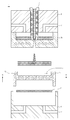
<82> 도 8은 본 발명의 제3실시예에 따른 급속가열 및 급속냉각 금형장치의 구성을 개략적으로 나타낸 단면도이고,8 is a cross-sectional view schematically showing the configuration of a rapid heating and rapid cooling mold apparatus according to a third embodiment of the present invention,
도 9는 도 8에 적용되는 유도가열 코일시트를 나타낸 평면도이다.Fig. 9 is a plan view showing an induction heating coil sheet applied to Fig. 8. Fig.
<83> 본 실시예에서의 금형장치(1)는 전술한 제2실시예에서와 대동소이하며, 동일한 구성요소에 대해서는 동일한 부The
호를 부여하였다. 다만, 본 실시예에서는 전술한 제2실시예와 달리 유도전류가 인가되는 단일의 워크 코일을 평. However, in this embodiment, unlike the above-described second embodiment, a single work coil to which an induction current is applied is flat
면상으로 연속적으로 굽힘 성형하여 시트 형태로 된 워크 코일시트(22)를 사용한다.A work-
<84> 이러한 워크 코일시트(22)는 나사부재 또는 용접을 통해 성형 코어(4c)의 일측면, 즉, 캐비티(c)가 형성된 반대The
면측에 부착구비되며, 상기 캐비티(c)와의 거리를 최소화 될 수 있게 상기 캐비티(c)의 반대측면에 상기 캐비티(C) is provided on the opposite side of the cavity (c) so as to minimize the distance from the cavity (c)
(c)를 수용할 수 있을 정도의 면적을 갖는 장착홈(mh)을 형성하고, 이 장착홈(mh)에 일면이 접촉될 수 있게 구(mh) having an area enough to accommodate the mounting groove (c), and a mounting groove
비되는 것이 바람직하다..
<85> 미설명 부호 (ch)는 상형판(3)과 하형판(4)에 형성되는 냉각홀을 나타낸 것이다.The reference character ch denotes a cooling hole formed in the
<86> 상기와 같이 구성되는 제3실시예에 따른 급속가열 및 급속냉각 금형장치의 작용을 설명하면 다음과 같다.The operation of the rapid heating and rapid cooling mold apparatus according to the third embodiment will be described as follows.
금형장치(1)를 구성하는 상형판(3)과 하형판(4)이 형합되어 성형 코어(3c)와 성형 코어(4c)가 서로 밀폐된 캐비The
티(c)를 형성한 상태에서, 상기 상형판(3)의 일측에 연결된 노즐(7)로부터 캐비티(c) 내로 용융 수지가 주입되면, 상기 금형장치(1)는 고주파 발진기(30)를 가동시켜 워크 코일시트(22)에 고주파 전류를 인가한다.When molten resin is injected into the cavity c from the
이어서, 상기 성형 코어(4c)는 워크 코일시트(22)와 접촉되는 면을 통해 <88> 국부 가열을 통해 결과적으로 전술한Subsequently, the shaped
실시예들과 마찬가지로 캐비티(c)의 표면에 대한 가열이 이루어지므로, 상기 캐비티(c)내에 주입된 수지의 유동Since the heating is performed on the surface of the cavity (c) as in the embodiments, the flow of the resin injected into the cavity (c)
특성 환경을 양호하게 조성할 수 있게 된다.The characteristic environment can be favorably formed.
<89> 따라서, 상기 고주파 유도가열을 이용하여 금형장치(1)의 국부 즉, 캐비티(c)의 표면에 대한 국부 가열을 순간Therefore, local heating of the local portion of the
적으로 실시하여 상기 캐비티(c)내의 수지 유동특성을 양호하게 조성함과 동시에 냉각시에는 성형 코어(4c)와So that the resin flow characteristics in the cavity (c) are favorably formed and at the time of cooling, the
상형판(3) 및 하형판(4)에 형성된 냉각홀(ch)을 통해 급속한 냉각을 실시하여 상기 캐비티(c)내의 수지 고화속(C) through the cooling holes (ch) formed in the upper mold plate (3) and the lower mold plate (4)
도를 단축시켜 생산성을 높일 수 있다.The productivity can be improved.
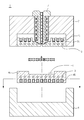
<90> 도 10은 본 발명의 제4실시예에 따른 급속가열 및 급속냉각 금형장치의 구성을 개략적으로 나타낸 단면도이고,10 is a cross-sectional view schematically showing the structure of a rapid heating and rapid cooling mold apparatus according to a fourth embodiment of the present invention,
도 11은 도 10의 ″C-C″ 방향에서 바라본 요부 구성을 나타낸 사시도이다.11 is a perspective view showing a configuration of a recess as viewed from the direction of " C-C " in Fig.
<91> 도면에서 보는 바와 같이, 본 실시예에서의 금형장치(1)는 전술한 제1실시예와 마찬가지로 상형판(3)과 하형판As shown in the figure, the
(4)으로 구성되고, 이들 상형판(3)과 하형판(4)은 상호 대향하는 방향으로 각각의 성형 코어(3c.4c)가 구비되는And the
구조로서, 여기서, 상기 성형 코어(3c.4c)는 서로 형합되는 것에 성형하고자 하는 제품의 형상과 동일한 형상의Wherein the formed cores (3c, 4c) have the same shape as the shape of the product to be molded
공간으로 된 캐비티(c)가 형성되어 있으며, 이때의 상기 캐비티(c)는 상기 상형판(3)의 일측에 연결된 노즐(7)The cavity (c) is formed with a nozzle (7) connected to one side of the upper plate (3)
로부터 수지를 공급받도록 구성되며, 이러한 구성은 공지의 기술에 의해 실시되는 것이므로 상세한 설명은 생략And this configuration is implemented by a known technique, so that a detailed description thereof will be omitted
한다.do.
<92> 다만, 본 실시예에서의 금형장치(1)는 상기 성형 코어(3c.4c)중 적어도 어느 하나 또는 둘 모두는 상기 캐비티However, in the
(c)의 반대면에 대응되는 면적에 대하여 국부 가열을 실시할 수 있도록 발열 코어(21)가 부착 구성되며, 본 발a
명의 도면에서는 성형 코어(3c.4c) 모두에 적용된 상태를 예시하고 있다.The figures show the state applied to all of the molded cores 3c.4c.
한편, 상기 성형 코어(3c.4c)는 상기 캐비티(c)의 반대면측에, 상기 캐비티(c)와 대응되는 면적에 대한 국부 가On the other hand, the molding core 3c.4c is provided on the opposite side of the cavity c with a local portion corresponding to the area corresponding to the cavity c
열을 하는 것으로 평면상으로 소용돌이 모양으로 가공되는 코일 설치홈(14)을 형성하는 구성이며, 상기 코일 설(14) which is formed into a spiral shape in a planar shape by performing heat,
치홈(14)에는 단일의 코일을 연속적으로 굽힙 성형하여서 된 소용돌이 모양을 갖는 워크 코일체(23)가A
구비된다.Respectively.
<94> 이러한 워크 코일체(23)는 전술한 실시예들과 마찬가지로 고주파 발진기(30)를 통해 고주파 전류를 인가받는 구As in the above-described embodiments, the work coils 23 are connected to the high-
성이며, 상기 성형 코어(3c.4c) 역시 전술한 실시예들과 동일하게 냉각수가 순환될 수 있게 냉각채널(13)이 형And the molded core 3c.4c also has the
성되는 구조이다.It is a structure to be built.
<95> 즉, 본 발명의 제 4실시예에 따른 급속가열 및 급속냉각 금형장치는, 전술한 제1실시예의 구성과 대동소이하다.That is, the rapid heating and rapid cooling mold apparatus according to the fourth embodiment of the present invention is similar to the structure of the first embodiment described above.
다만, 본 실시예에서는 전술한 제1실시예와 달리 유도전류가 인가되는 단일의 유도코일을 평면상으로 소용돌이However, unlike the first embodiment described above, in this embodiment, a single induction coil to which an induction current is applied,
모양으로 굽힘 성형하여 된 워크 코일체(23)를 적용하는 것이다.Shaped
<96> 이러한 워크 코일체(23)를 성형 코어(3c.4c)에 장착하기 위하여, 상기 성형 코어(3c.4c)는 캐비티(c)의 반대측In order to mount such a
면에 상기 워크 코일체(23)가 끼움될 수 있게 대응되는 형상으로 코일 설치홈(14)이 형성되는 것이며, 상기 워A
크 코일체(23)는 상기 코일 설치홈(14)에 끼워 맞춤으로 구비되거나 또는 용접 등을 통해 위치 고정될 수 있을The
것이다.will be.
<97> 한편 도시하지는 않았으나, 상기 워크 코일체(23)는 전술한 제2실시예와 마찬가지로 일측면에 알루미늄 또는 구Although not shown, the work coils 23 are made of aluminum or a spherical body on one side in the same manner as in the second embodiment described above,
리계열의 열전도성 금속재로 된 열평형판이 부착 구비될 수 있으며, 이 열평형판의 내부에는 냉각수가 순환되는A heat plate made of a heat conductive metal material may be attached to the heat plate, and cooling water is circulated inside the heat plate
냉각채널이 형성될 수 있으며, 이외에도 상기 성형 코어는 일측에 알루미늄 또는 구리계열의 열전도성 금속재로A cooling channel may be formed, and in addition, the formed core may be formed of aluminum or a copper-based thermally conductive metal material
된 열평형관이 매립 또는 끼움구조에 의해 구비될 수 있을 것이다.The thermal equilibrium tube may be provided by an embedding or fitting structure.
<98> 상기와 같이 구성되는 제4실시예에 따른 급속가열 및 급속냉각 금형장치의 작용을 설명하면 다음과 같다.Hereinafter, the operation of the rapid heating and rapid cooling mold apparatus according to the fourth embodiment will be described.
<99> 금형장치(1)를 구성하는 상형판(3)과 하형판(4)이 형합되어 성형 코어(3c)와 성형 코어(4c)가 서로 밀폐된 캐비The
티(c)를 형성한 상태에서, 상기 상형판(3)의 일측에 연결된 노즐(7)로부터 캐비티(c) 내로 용융 수지가 주입되The molten resin is injected into the cavity c from the
면, 상기 금형장치(1)는 고주파 발진기(30)를 가동시켜 워크 코일체(23)에 고주파 전류를 인가한다.The
이어서, 상기 성형 코어(4c)는 워크 코일시트(22)와 접촉되는 면을 통해 국부 가열을 통해 결과적으로 전술한The shaped
실시예들과 마찬가지로 캐비티(c)의 표면에 대한 가열이 이루어짐에 따라 수지의 유동특성 환경을 양호하게 조As in the embodiments, as the heating of the surface of the cavity (c) is performed, the flow characteristic environment of the resin is satisfactorily adjusted
성할 수 있게 된다.It is possible to grow.
<101> 또한, 성형 코어(3c.4c)에 형성된 냉각채널(13)을 순환하는 냉각수에 의해 신속한 냉각이 이루어진다.Also, the cooling water circulating through the cooling
따라서, 상기 고주파 유도가열을 이용하여 금형장치(1)의 국부 즉, 캐비티(<102> c)의 표면에 대한 국부 가열을 순간Therefore, by using the high-frequency induction heating, the local heating of the local portion of the
적으로 실시하여 상기 캐비티(c)내의 수지 유동특성을 양호하게 조성함과 동시에 냉각시에는 성형 코어(3c.4c)So that the resin flow characteristics in the cavity (c) are favorably formed, and at the time of cooling, the molded core (3c.4c)
에 형성된 냉각채널(13)에 냉각수를 순환공급시키는 구성을 통해 급속한 냉각을 실시하여 상기 캐비티(c)내의The cooling water is circulated through the cooling
수지 고화속도를 단축시켜 생산성을 높일 수 있다.The resin solidification rate can be shortened and the productivity can be increased.
<103> 한편, 본 발명은 기재된 실시예에 한정되는 것이 아니고, 본 발명의 사상 및 범위를 벗어나지 않고 다양하게 수While the present invention has been described with reference to exemplary embodiments, it is to be understood that the invention is not limited to the disclosed exemplary embodiments, but, on the contrary,
정 및 변형을 할 수 있음은 이 기술 분야에서 통상의 지식을 가진 자에게는 자명하다. 따라서, 그러한 변형예It will be apparent to those skilled in the art that various modifications, additions and substitutions are possible, without departing from the scope of the invention. Therefore,
또는 수정예들은 본 발명의 특허청구범위에 속한다 해야 할 것이다.Or modifications are intended to fall within the scope of the appended claims.
1 : 금형장치 3 : 상형판
<117> 3c : 성형 코어 4 : 하형판
<118> 4c : 성형 코어 7 : 노즐
<119> 11 : 코일홈 13 : 냉각채널
<120> 14 : 코일 설치홈 20 : 발열 코어부
<121> 21 : 발열 코어 22 : 워크 코일시트
<122> 23 : 워크 코일체 25 : 워크 코일
<123> 30 : 고주파 발진기 40 : 열평형판
<124> 43 : 냉각채널 c : 캐비티
<125> mh : 장착홈1: mold apparatus 3: upper mold plate
3c: Molded core 4: Lower mold plate
4c: forming core 7: nozzle
11: coil groove 13: cooling channel
14: coil mounting groove 20: heating core part
21: heat generating core 22: work coil sheet
23: work coils 25: work coils
30: high frequency oscillator 40: thermal equilibrium plate
43: cooling channel c: cavity
<125> mh: Mounting groove
Claims (12)
상기 성형 코어는 상기 캐비티의 반대면에 대응되는 면적에 국부 가열을 하는 것으로 코일홈을 따라 워크 코일
이 권선되어 이루어진 발열 코어부와;
상기 워크 코일에 선택적으로 유도전류를 인가하여 발열 코어부를 발열시키는 고주파 발진기와;
상기 성형 코어의 내부에 형성되어 냉각수가 순환되는 냉각채널;
을 포함하여 구성되는 것을 특징으로 하는 급속가열 및 급속냉각 금형장치.A mold apparatus comprising a molding core in which a cavity for receiving molten resin from a nozzle is formed,
The molding core is subjected to local heating at an area corresponding to the opposite surface of the cavity,
A heat generating core portion wound on the heat generating core portion;
A high frequency oscillator for selectively generating an induction current to the work coil to generate heat in the heat generating core;
A cooling channel formed inside the molding core to circulate cooling water;
Wherein the fast cooling and rapid cooling mold apparatus comprises:
판이 부착 구비되고, 이 열평형판은 그 내부에 냉각수가 순환되는 냉각채널이 형성된 것을 특징으로 하는 급속
가열 및 급속냉각 금형장치.The heat-generating core according to claim 1, wherein the heat-generating core portion is a heat-balanced core made of an aluminum or copper-
And a cooling channel through which cooling water is circulated is formed in the thermal equilibrium plate,
Heating and rapid cooling mold devices.
또는 끼움구조에 의해 구비되는 것을 특징으로 하는 급속가열 및 급속냉각 금형장치.The method according to claim 1, wherein the molded core comprises a thermally-balanced tube made of a thermally conductive metal material of aluminum or copper series on one side,
Or a fastening structure for fast cooling the mold.
상기 성형 코어는 상기 캐비티의 반대면에 대응되는 면적에 국부 가열을 하는 것으로 워크 코일이 권선된 발열
코어와;
상기 워크 코일에 선택적으로 유도전류를 인가하여 발열 코어를 발열시키는 고주파 발진기와;
상기 성형 코어의 내부에 형성되어 냉각수가 순환되는 냉각채널;
을 포함하여 구성되는 것을 특징으로 하는 급속가열 및 급속냉각 금형장치.A mold apparatus comprising a molding core in which a cavity for receiving molten resin from a nozzle is formed,
The molding core is subjected to local heating at an area corresponding to the opposite surface of the cavity,
A core;
A high frequency oscillator which generates heat by selectively applying an induction current to the work coil;
A cooling channel formed inside the molding core to circulate cooling water;
Wherein the fast cooling and rapid cooling mold apparatus comprises:
구비되는 것을 특징으로 하는 급속가열 및 급속냉각 금형장치.The heat generating core according to claim 4, wherein the heat generating core has a heat-balanced plate made of aluminum or a copper-based thermally conductive metal material on one side
Wherein the fast cooling and rapid cooling mold apparatus is provided with a fast cooling mechanism.
열 및 급속냉각 금형장치.[6] The apparatus of claim 5, wherein the thermal equilibrium plate is formed with a cooling channel through which cooling water is circulated.
Thermal and rapid cooling mold devices.
또는 끼움구조에 의해 구비되는 것을 특징으로 하는 급속가열 및 급속냉각 금형장치.The method according to claim 4, wherein the molded core comprises a thermally-balanced tube made of an aluminum or copper-based thermally conductive metal material,
Or a fastening structure for fast cooling the mold.
하는 급속가열 및 급속냉각 금형장치[5] The apparatus of claim 4, wherein the heat generating core comprises at least two heating coils and is wound with one work coil
Rapid heating and rapid cooling mold apparatus
일의 코일을 평면상으로 연속적으로 굽힘 성형하여 된 워크 코일 시트와;
상기 워크 코일시트에 선택적으로 유도전류를 인가하여 발열 코어를 발열시키는 고주파 발진기와;
상기 성형 코어의 내부에 형성되어 냉각수가 순환되는 냉각채널;
을 포함하여 구성되는 것을 특징으로 하는 급속가열 및 급속냉각 금형장치.And a molding core in which a cavity for receiving molten resin from the nozzle is formed, wherein the molding core is attached to the opposite surface of the cavity to perform local heating with respect to the area corresponding to the cavity,
A work coil sheet formed by continuously bending a work coil in a plane;
A high frequency oscillator which generates heat by selectively applying an induction current to the work coil sheet;
A cooling channel formed inside the molding core to circulate cooling water;
Wherein the fast cooling and rapid cooling mold apparatus comprises:
상기 성형 코어는 상기 캐비티의 반대면에 부착되어 캐비티에 대응되는 면적에 대한 국부가열을 하는 것으로 평
면상에 소용돌이 모양으로 가공되는 코일 설치홈과;
상기 코일 설치홈에 끼움 구비되는 것으로 코일을 연속적으로 굽힘 성형하여 된 워크 코일체와;
상기 성형 코어의 내부에 형성되어 냉각수가 순환되는 냉각채널;
를 포함하여 구성되는 것을 특징으로 하는 급속가열 및 급속냉각 금형장치A mold apparatus comprising a molding core in which a cavity for receiving molten resin from a nozzle is formed,
The molding core is attached to the opposite surface of the cavity to perform local heating with respect to the area corresponding to the cavity.
A coil mounting groove machined into a spiral shape on the surface;
A work coil integral with the coil mounting groove and continuously bending the coil;
A cooling channel formed inside the molding core to circulate cooling water;
Wherein the rapid heating and rapid cooling mold device
부착 구비되고, 이 열평형판의 내부에는 냉각수가 순환되는 냉각채널이 형성된 것을 특징으로 하는 급속가열 및
급속냉각 금형장치The workpiece assembly according to claim 10, wherein the work coils comprise a heat flat plate made of aluminum or a copper-based thermally conductive metal material on one side,
And a cooling channel through which cooling water is circulated is formed in the inside of the thermal equilibrium plate.
Rapid cooling mold device
또는 끼움구조에 의해 구비되는 것을 특징으로 하는 급속가열 및 급속냉각 금형장치
The method according to claim 4, wherein the molded core comprises a thermally-balanced tube made of an aluminum or copper-based thermally conductive metal material,
Or fastening structure, characterized in that the fast heating and rapid cooling mold device
Priority Applications (1)
| Application Number | Priority Date | Filing Date | Title |
|---|---|---|---|
| KR1020160072857A KR20170140497A (en) | 2016-06-13 | 2016-06-13 | Mold device using high-frequency induction heating |
Applications Claiming Priority (1)
| Application Number | Priority Date | Filing Date | Title |
|---|---|---|---|
| KR1020160072857A KR20170140497A (en) | 2016-06-13 | 2016-06-13 | Mold device using high-frequency induction heating |
Publications (1)
| Publication Number | Publication Date |
|---|---|
| KR20170140497A true KR20170140497A (en) | 2017-12-21 |
Family
ID=60936047
Family Applications (1)
| Application Number | Title | Priority Date | Filing Date |
|---|---|---|---|
| KR1020160072857A KR20170140497A (en) | 2016-06-13 | 2016-06-13 | Mold device using high-frequency induction heating |
Country Status (1)
| Country | Link |
|---|---|
| KR (1) | KR20170140497A (en) |
Cited By (2)
| Publication number | Priority date | Publication date | Assignee | Title |
|---|---|---|---|---|
| CN107891580A (en) * | 2017-12-27 | 2018-04-10 | 宁波秦鼎材料科技有限公司 | A kind of core can heat the high polymer material injection mold of the refrigeration demoulding |
| CN108687329A (en) * | 2018-08-13 | 2018-10-23 | 华南理工大学广州学院 | Has the casting device of temperature control core |
-
2016
- 2016-06-13 KR KR1020160072857A patent/KR20170140497A/en unknown
Cited By (3)
| Publication number | Priority date | Publication date | Assignee | Title |
|---|---|---|---|---|
| CN107891580A (en) * | 2017-12-27 | 2018-04-10 | 宁波秦鼎材料科技有限公司 | A kind of core can heat the high polymer material injection mold of the refrigeration demoulding |
| CN107891580B (en) * | 2017-12-27 | 2019-09-17 | 宁波秦鼎材料科技有限公司 | A kind of type core can heat the high molecular material injection mold of refrigeration demoulding |
| CN108687329A (en) * | 2018-08-13 | 2018-10-23 | 华南理工大学广州学院 | Has the casting device of temperature control core |
Similar Documents
| Publication | Publication Date | Title |
|---|---|---|
| TWI389600B (en) | Coaxial cooling and rapid conductive coil construction and molds with cobalt cooling and rapid conductive coil construction | |
| JP6770505B2 (en) | A device for heating the molding surface of a mold | |
| TWI415729B (en) | Mold with the uniform heating and cooling structure | |
| KR100850308B1 (en) | Synthetic resin molding mold | |
| US6846445B2 (en) | Method for rapid mold heating and cooling | |
| US8963058B2 (en) | System and method of adjusting the equilibrium temperature of an inductively-heated susceptor | |
| CN101909839B (en) | System and method for forming polymer | |
| US20100201040A1 (en) | Induction heating device and method for making parts using same | |
| JP5467774B2 (en) | Tire vulcanizer | |
| JP2007531200A (en) | Heating system and method | |
| KR20070008630A (en) | Method of heating materials in order to produce objects and device for implementing said method | |
| US20090014439A1 (en) | Non-Contact High-Frequency Induction Heating Apparatus for Plastic Mold and Injection Nozzle Thereof | |
| CN102245365A (en) | Device for converting materials using induction heating that enables preheating of the device | |
| KR20170140497A (en) | Mold device using high-frequency induction heating | |
| US10232530B2 (en) | Induction heating device and method for making a workpiece using such a device | |
| JP3896461B2 (en) | Precision mold | |
| KR20090029318A (en) | Quick heating and quick cooling for mold | |
| JP2013000947A (en) | Workpiece forming mold | |
| JP6691649B2 (en) | Electromagnetic induction heating type resin molding die and method of manufacturing resin molding using the die | |
| CN108322946B (en) | Electric heating type full-closed loop heating device | |
| TW201417984A (en) | Uniformly rapid heating of the mold equipment | |
| CN1988997A (en) | Heater unit and thermal fusion apparatus for synthetic resin members and thermal fusion method for synthetic resin members | |
| TWI353293B (en) | ||
| KR20170002435A (en) | Device for heating a mold | |
| TW201302411A (en) | Mold equipment with uniform and fast heating |
Legal Events
| Date | Code | Title | Description |
|---|---|---|---|
| N231 | Notification of change of applicant |