KR20170140233A - Electronic modules for transmission control devices - Google Patents
Electronic modules for transmission control devices Download PDFInfo
- Publication number
- KR20170140233A KR20170140233A KR1020177030978A KR20177030978A KR20170140233A KR 20170140233 A KR20170140233 A KR 20170140233A KR 1020177030978 A KR1020177030978 A KR 1020177030978A KR 20177030978 A KR20177030978 A KR 20177030978A KR 20170140233 A KR20170140233 A KR 20170140233A
- Authority
- KR
- South Korea
- Prior art keywords
- sensor
- dome
- sensor element
- casting compound
- conductor foil
- Prior art date
Links
Images


Classifications
-
- H—ELECTRICITY
- H05—ELECTRIC TECHNIQUES NOT OTHERWISE PROVIDED FOR
- H05K—PRINTED CIRCUITS; CASINGS OR CONSTRUCTIONAL DETAILS OF ELECTRIC APPARATUS; MANUFACTURE OF ASSEMBLAGES OF ELECTRICAL COMPONENTS
- H05K5/00—Casings, cabinets or drawers for electric apparatus
- H05K5/0026—Casings, cabinets or drawers for electric apparatus provided with connectors and printed circuit boards [PCB], e.g. automotive electronic control units
- H05K5/0082—Casings, cabinets or drawers for electric apparatus provided with connectors and printed circuit boards [PCB], e.g. automotive electronic control units specially adapted for transmission control units, e.g. gearbox controllers
-
- H—ELECTRICITY
- H05—ELECTRIC TECHNIQUES NOT OTHERWISE PROVIDED FOR
- H05K—PRINTED CIRCUITS; CASINGS OR CONSTRUCTIONAL DETAILS OF ELECTRIC APPARATUS; MANUFACTURE OF ASSEMBLAGES OF ELECTRICAL COMPONENTS
- H05K7/00—Constructional details common to different types of electric apparatus
- H05K7/20—Modifications to facilitate cooling, ventilating, or heating
- H05K7/2039—Modifications to facilitate cooling, ventilating, or heating characterised by the heat transfer by conduction from the heat generating element to a dissipating body
- H05K7/20436—Inner thermal coupling elements in heat dissipating housings, e.g. protrusions or depressions integrally formed in the housing
- H05K7/20445—Inner thermal coupling elements in heat dissipating housings, e.g. protrusions or depressions integrally formed in the housing the coupling element being an additional piece, e.g. thermal standoff
- H05K7/20463—Filling compound, e.g. potted resin
Abstract
본 발명은 전자 회로(14)를 가진 변속기 제어 유닛(12), 적어도 하나의 캐리어 요소(16) 및 적어도 하나의 센서 돔(18)을 포함하는, 자동차의 변속기 제어 장치용 전자 모듈(10)에 관한 것이다. 센서 돔은 일 단부(24)에 전자 센서 요소(26)를 포함하며, 상기 센서 요소는 적어도 2개의 전기 라인(30)을 포함하고, 상기 전리 라인들은 각각 접촉점(32)에서 커버 층과 베이스 층 사이에 배치된 도체 포일(28)의 도체 트랙(34)에 전기 전도 방식으로 연결된다. 센서 요소는 적어도 센서 요소의 외주에 센서 요소를 전체적으로 둘러싸는 주조 화합물(38)로 오버몰딩된다. 본 발명에 따른 전자 모듈은 특히, 센서 요소의 적어도 2개의 전기 라인들, 접촉점들 및 도체 포일의 영역(40)이 주조 화합물에 의해 오버 몰딩되어, 전기 라인들 및 접촉점들이 주조 화합물에 의해 서로 분리되어 있는 것을 특징으로 한다. 이로 인해, 전자 모듈의 견고성이 전체적으로 증가될 수 있다. The present invention relates to an electronic module 10 for a transmission control device of a motor vehicle comprising a transmission control unit 12 with electronic circuitry 14, at least one carrier element 16 and at least one sensor dome 18, . The sensor dome includes an electronic sensor element 26 at one end 24 that includes at least two electrical lines 30 which are respectively at the contact point 32 and a cover layer, To the conductor track 34 of the conductor foil 28 disposed between the conductor foil 28 and the conductor foil 28. The sensor element is overmolded with at least a casting compound (38) that entirely surrounds the sensor element on the periphery of the sensor element. In particular, the electronic module according to the invention is characterized in that at least two electrical lines, contact points and areas of the conductor foil of the sensor element are overmolded by the casting compound so that the electrical lines and contact points are separated . As a result, the robustness of the electronic module can be increased as a whole.
Description
본 발명은 일반적으로 전자 모듈에 관한 것이다. 특히, 본 발명은 자동차의 변속기 제어 장치용 센서 요소를 갖는 전자 모듈에 관한 것이다.The present invention relates generally to electronic modules. In particular, the present invention relates to an electronic module having a sensor element for a transmission control device of an automobile.
자동차 내의 변속기, 특히 자동 변속기의 제어를 위해, 일반적으로 전자 회로를 갖는 변속기 제어 유닛("transmission control unit", TCU), 차량 케이블 하니스에 연결하기 위한 적어도 하나의 플러그 연결부, 액추에이터를 작동시키기 위한 전기 인터페이스, 및 적어도 하나의 센서 요소를 포함하는 전자 모듈이 사용된다.A transmission control unit (TCU) generally having electronic circuitry, at least one plug connection for connection to a vehicle cable harness, an electric motor for actuating the actuator, An interface, and at least one sensor element.
센서 요소들은 특히 회전 속도를 결정하도록 및/또는 변속기 내의 경로들 또는 위치들을 결정하도록 설계될 수 있다. 예를 들어, 이러한 센서 요소는 홀 센서로서, 예를 들어 집적 회로("Integrated Circuits", IC)의 형태로 또는 주문형 집적 회로("Application-Specific Integrated Circuits", ASIC)의 형태로 구현될 수 있다.The sensor elements may be specifically designed to determine the rotational speed and / or determine the paths or positions within the transmission. For example, such sensor elements may be implemented as Hall sensors, for example in the form of integrated circuits ("ICs") or in the form of "Application-Specific Integrated Circuits" (ASICs) .
일반적으로, 센서 요소의 접속 와이어들 또는 전기 라인들은 중간 리드 프레임에 용접되며, 상기 서브 어셈블리는 플라스틱 돔 또는 돔 본체에 장착된 다음 주조 화합물로, 예컨대 에폭시수지 기반, 실리콘 기반 및/또는 폴리우레탄 기반 주조 화합물로 성형되어 소위 센서 돔을 형성할 수 있다. 대안으로서, 상기 서브 어셈블리는 센서 요소의 영역에서 열경화성 재료로 오버몰딩될 수 있으며, 실제 센서 돔은 예를 들어 열가소성 재료로 다른 공정 단계에서 성형될 수 있다.Generally, the connecting wires or electrical lines of the sensor element are welded to an intermediate leadframe, which is mounted on a plastic dome or dome body and is then cast as a casting compound, for example epoxy based, silicon based and / or polyurethane based So that a so-called sensor dome can be formed. Alternatively, the subassembly may be overmolded with a thermosetting material in the region of the sensor element, and the actual sensor dome may be molded, for example, with a thermoplastic material at another process step.
그런 다음 센서 돔은 전자 모듈에 장착되고 전자 모듈의 컴포넌트들, 특히 변속기 제어 유닛의 전자 회로와 전기적으로 접촉될 수 있다.The sensor dome can then be mounted on the electronic module and electrically contact the components of the electronic module, particularly the electronic circuitry of the transmission control unit.
EP 1 239 710 A2는 센서 요소가 용접에 의해 도체 포일에 전기 전도 방식으로 연결되는 전자 서브 어셈블리를 개시한다.EP 1 239 710 A2 discloses an electronic subassembly in which a sensor element is electrically connected to a conductor foil by welding.
본 발명의 과제는 자동차의 변속기 제어 장치를 위한 강하고, 신뢰성 있고, 경제적으로 생산 가능한 전자 모듈을 제공하는 것이다.An object of the present invention is to provide a strong, reliable and economically producible electronic module for a transmission control device of an automobile.
본 발명의 실시 예들은 바람직하게는 자동차의 변속기 제어 장치를 위한 강하고, 신뢰성 있고, 경제적으로 생산 가능한 전자 모듈을 제공하는 것을 허용한다.Embodiments of the present invention preferably allow for providing a robust, reliable, and economically producible electronic module for a transmission control device of an automobile.
본 발명의 일 양상에 따르면, 전자 회로를 가진 변속기 제어 유닛, 적어도 하나의 캐리어 요소 및 적어도 하나의 센서 돔을 포함하는, 자동차의 변속기 제어 장치용 전자 모듈이 제공된다. 센서 돔은 길게 형성된 돔 본체를 포함하고, 상기 돔 본체의 제 1 단부는 캐리어 요소 상에 배치되며, 상기 돔 본체는 인쇄 회로 기판 요소로부터 돌출하고, 상기 센서 돔은 제 1 단부에 대향하는 제 2 단부에 전자 센서 요소를 포함하며, 상기 전자 센서 요소는 적어도 2개의 전기 라인을 포함하고, 상기 전리 라인들은 각각 접촉점에서 커버 층과 베이스 층 사이에 배치된 도체 포일의 도체 트랙에 전기 전도 방식으로 연결된다. 도체 포일의 도체 트랙은 각각 변속기 제어 유닛의 전자 회로에 전기 전도 방식으로 연결되고, 센서 요소는 적어도 센서 요소의 외주에서 센서 요소를 전체적으로 둘러싸는 주조 화합물로 오버몰딩된다. 본 발명에 따른 전자 모듈은 특히, 센서 요소의 적어도 2개의 전기 라인들, 접촉점들 및 도체 포일의 영역이 주조 화합물에 의해 오버 몰딩되어, 전기 라인들 및 접촉점들이 주조 화합물에 의해 서로 분리되어 있는 것을 특징으로 한다. 주조 화합물은 센서 요소와 함께 센서 돔의 커버 요소를 형성할 수 있다. 주조 화합물은 센서 요소들, 접촉점들 및 라인들용 일종의 캡슐을 제공할 수 있고, 상기 캡슐은 전자 모듈 주위로 흐르는 변속기 유체에 대해 밀봉할 수 있다.According to an aspect of the invention, there is provided an electronic module for a transmission control device of a vehicle, comprising a transmission control unit with electronic circuitry, at least one carrier element and at least one sensor dome. The sensor dome includes a long dome body, the first end of the dome body being disposed on a carrier element, the dome body protruding from a printed circuit board element, and the sensor dome having a second Wherein the ionization element comprises at least two electrical lines, each of the ionization lines electrically connected to a conductor track of a conductor foil disposed between the cover layer and the base layer at a contact point, do. The conductor tracks of the conductor foil are each electrically conductively connected to the electronic circuit of the transmission control unit and the sensor element is overmolded with a casting compound which entirely surrounds the sensor element at least at the periphery of the sensor element. In particular, the electronic module according to the invention is characterized in that at least two electrical lines of the sensor element, contact points and regions of the conductor foil are overmolded by the casting compound so that the electrical lines and contact points are separated from each other by the casting compound . The casting compound may form a cover element of the sensor dome with the sensor element. The cast compound can provide a kind of capsule for sensor elements, contact points and lines, and the capsule can seal against the transmission fluid flowing around the electronic module.
캐리어 요소는 기계적 캐리어 요소, 예컨대 센서 돔이 고정될 수 있는 기계적 캐리어 구조일 수 있다. 캐리어 요소는 적어도 하나의 리드 프레임을 포함할 수 있고 및/또는 나타낼 수 있다. 또한, 캐리어 요소는 적어도 하나의 인쇄 회로 기판 요소 및/또는 인쇄 회로 기판, 예컨대 HDI("High-Density Interconnect") 인쇄 회로 기판 요소 및/또는 PCB("Printed Circuit Board") 인쇄 회로 기판 요소를 포함할 수 있다.The carrier element may be a mechanical carrier element, such as a mechanical carrier structure to which the sensor dome may be fixed. The carrier element may and / or may include at least one lead frame. The carrier element also includes at least one printed circuit board element and / or a printed circuit board, such as a High-Density Interconnect (HDI) printed circuit board element and / or a printed circuit board (PCB) can do.
제조 기술적으로, 접촉점들에서 도체 포일의 도체 트랙들에 접촉될 수 있는 전기 라인들을 가진 센서 요소는 예컨대 열 경화성 재료 및/또는 열 가소성 재료로 예비 제조된 돔 본체의 제 2 단부 상에 포지셔닝된 다음, 센서 요소, 접촉점을 가진 라인 및 도체 포일의 영역이 주조 화합물로 오버몰딩될 수 있다. 이 경우, 라인들과 접촉점들은 주조 화합물로 특히 완전히 오버몰딩됨으로써, 라인들과 접촉점들은 주조 화합물 내에 완전히 매립되거나 주조 화합물 내에 주조될 수 있다. 접촉점들 및/또는 라인들은 주조 화합물에 의해 밀봉 방식으로 둘러싸일 수 있다. 도체 포일의 일 면이 돔 본체 상에 놓이고, 대향 측면 상에 접촉점들이 배치될 수 있다. 따라서, 주조 화합물로 오버몰딩된 도체 포일의 영역은 예컨대 도체 포일의 일 단부의 적어도 하나의 면일 수 있다. 센서 요소의 라인들 및 접촉점들을 본 발명에 따라 오버몰딩함으로써, 전자 모듈 주위로 흐르는 변속기 유체 내에 존재할 수 있는 예컨대 전기 전도성 칩, 도전성 침적물, 예컨대 황화구리 및/또는 도전성 매체에 의해 야기될 수 있는 라인들 사이의 단락 및/또는 분로가 바람직하게 방지될 수 있다. 이러한 방식으로, 주조 화합물에 의한 오버몰딩은 특히 센서 돔 및/또는 전자 모듈을 칩으로부터 보호할 수 있는데, 그 이유는 예컨대 변속기 유체가 센서 요소의 라인들 및/또는 접촉점들까지 침투할 수 없기 때문이다. 전체적으로, 센서 돔 및/또는 전자 모듈의 강성이 증가될 수 있다.Manufacturing Technically, a sensor element having electrical lines that can be contacted with the conductor tracks of the conductor foil at the contact points is positioned on the second end of the dome body, e.g., made of thermosetting material and / or thermoplastic material, , The sensor element, the line with the contact point and the area of the conductor foil can be overmolded with the casting compound. In this case, the lines and contact points can be completely embedded in the casting compound or cast into the casting compound, especially by being completely overmolded with the casting compound. The contact points and / or lines may be encapsulated by the casting compound. One side of the conductor foil is placed on the dome body, and the contact points can be placed on opposite sides. Thus, the area of the conductor foil overmoulded with the casting compound may be at least one side of one end of the conductor foil, for example. By overmolding the lines and contact points of the sensor element in accordance with the present invention, it is possible to overcome the problems of the present invention by, for example, electrically conductive chips, conductive deposits, such as copper sulfide, which may be present in the transmission fluid flowing around the electronic module, and / A short circuit and / or a shunt can be preferably prevented. In this way, overmolding by the casting compound can in particular protect the sensor dome and / or the electronic module from the chip, for example because the transmission fluid can not penetrate into the lines and / or contact points of the sensor element to be. Overall, the stiffness of the sensor dome and / or electronic module can be increased.
또한, 센서 요소의 라인과 도체 포일의 도체 트랙과의 직접적인 접촉에 의해 중간 리드 프레임이 생략될 수 있어서, 전자 모듈의 제조 비용 및 부품들이 줄어들 수 있다.Further, the direct contact between the line of the sensor element and the conductor track of the conductor foil can eliminate the intermediate lead frame, so that the manufacturing cost and parts of the electronic module can be reduced.
센서 요소는 예를 들어 SMD("Surface Mounted Device") 모듈, ASIC 및/또는 IC일 수 있다. 센서 요소는 열 경화성 재료 또는 다른 적합한 재료로 오버몰딩된 회로를 포함할 수 있고, 센서 요소의 라인들은 하우징의 재료 내로 반드시 밀봉 방식으로 매립될 필요는 없다. 주조 화합물로 센서 요소의 오버몰딩에 의해, 상기 영역들이 확실하게 그리고 포괄적으로 밀봉될 수 있다. 또한 주조 화합물에 의한 오버몰딩에 의해, 라인의 주석 도금이 생략될 수 있고, 이는 위스커(Wisker) 경향을 없애고 주석과 같은 비싼 재료의 사용을 줄일 수 있다. 주조 화합물은 구리로 제조될 수 있는 센서 요소의 라인들 및 센서 요소의 하우징에, 특히 이것이 플라즈마 세척되고 및/또는 활성화되면, 밀봉 방식으로 그리고 견고하게 접착될 수 있다. 이로 인해 견고하고 확실하게 밀봉된 센서 돔이 제공될 수 있다.The sensor element may be, for example, an SMD ("Surface Mounted Device") module, an ASIC and / or an IC. The sensor element may comprise a circuit overmolded with a thermosetting material or other suitable material, and the lines of the sensor element need not necessarily be filled in a sealed manner into the material of the housing. By overmolding the sensor element with the casting compound, the areas can be reliably and comprehensively sealed. Also, by overmolding by the casting compound, tin plating of the lines can be omitted, which can eliminate the tendency of the whisker and reduce the use of expensive materials such as tin. The casting compound can be bonded to the housing of the sensor element and the lines of the sensor element, which can be made of copper, in a sealed manner and firmly, especially when it is plasma cleaned and / or activated. This makes it possible to provide a sensor dome that is firmly and reliably sealed.
센서 요소는 도체 포일과 함께 표준 공정에서 예비 제작될 수 있고, 상기 서브 어셈블리는 경우에 따라 자동화되어 전자 모듈의 제조 동안 돔 본체 상에 포지셔닝되고 주조 화합물로 주조된다. 이로 인해, 전자 모듈의 제조 비용이 더 줄어들 수 있다. 또한, 센서 요소 및/또는 센서 돔의 모듈 맞춤형 변형 예가 예비 제조 및/또는 형성될 수 있고, 이는 전자 모듈의 제조를 더욱 단순화할 수 있다.The sensor element may be pre-fabricated in a standard process with a conductor foil, which is optionally automated and positioned on the dome body during the manufacture of the electronic module and cast into a casting compound. As a result, the manufacturing cost of the electronic module can be further reduced. Also, a module customized variant of the sensor element and / or the sensor dome can be preliminarily manufactured and / or formed, which can further simplify the manufacture of the electronic module.
본 발명의 일 실시 예에 따라, 도체 포일은 센서 리세스를 포함하고, 센서 요소는 센서 본체를 포함한다. 상기 센서 본체는 도체 포일의 센서 리세스 내에 배치되므로, 도체 포일의 부분 영역이 외주에서 센서 본체를 둘러싼다. 센서 리세스는 주조 화합물로 적어도 부분적을 분무될 수 있다. 이는 돔 본체 상에 센서 요소의 포지셔닝을 단순화 및/또는 개선할 수 있는데, 그 이유는 예컨대 도체 포일의 적어도 하나의 가장자리가 예컨대 도체 포일의 적어도 하나의 가장자리와 돔 본체의 가장자리 또는 외부 에지의 동일 평면 정렬에 의해, 돔 본체 상에 센서 요소의 정렬 및/또는 포지셔닝에 사용될 수 있기 때문이다.According to one embodiment of the invention, the conductor foil comprises a sensor recess, and the sensor element comprises a sensor body. Since the sensor body is disposed in the sensor recess of the conductor foil, a partial region of the conductor foil surrounds the sensor body at the outer periphery. The sensor recess can be at least partially sprayed with the casting compound. This can simplify and / or improve the positioning of the sensor element on the dome body, since at least one edge of the conductor foil can be positioned, for example, on at least one edge of the conductor foil and in the same plane of the edge or outer edge of the dome body Or alignment of the sensor elements on the dome body.
본 발명의 일 실시 예에 따라, 도체 포일의 부분 영역 상에 배치된 도체 포일의 외부 에지 및/또는 가장자리는 돔 본체 상에 센서 요소를 배치하기 위해 돔 본체의 외부 에지와 동일 평면으로 끝난다. 돔 본체의 외부 에지는 예컨대 센서 요소 및 도체 포일의 부분 영역이 적어도 부분적으로 놓일 수 있는 돔 본체의 지지면의 외부 에지일 수 있다. 도체 포일의 다수의 가장자리 또는 외부 에지가 돔 본체의 외부 에지와 동일 평면으로 끝나므로, 센서 요소는 돔 본체의 지지면 상에 2개의 직교하는 공간 방향으로 배치될 수 있다. 센서 본체를 둘러싸는 도체 포일의 부분 영역은 주조 화합물 내로 적어도 부분적으로 매립 또는 주입될 수 있다.According to one embodiment of the present invention, the outer edge and / or the edge of the conductor foil disposed on the partial area of the conductor foil end flush with the outer edge of the dome body to place the sensor element on the dome body. The outer edge of the dome body may be, for example, the outer edge of the support surface of the dome body, where the sensor element and the partial area of the conductor foil may be at least partially resting. The sensor elements can be arranged in two orthogonal spatial directions on the support surface of the dome body, since a plurality of edges or outer edges of the conductor foil end flush with the outer edges of the dome body. The partial area of the conductor foil surrounding the sensor body may be at least partially buried or injected into the casting compound.
본 발명의 일 실시 예에 따라, 센서 리세스는 접촉점들 사이에 배치된 도체 포일의 리세스와 함께 도체 포일의 연속하는 리세스를 형성하고, 상기 연속하는 리세스는 주조 화합물로 적어도 부분적으로 분무된다. 센서 리세스 및/또는 상기 리세스는 예컨대 도체 포일 내에 펀칭된 구멍일 수 있다. 접촉점들 사이의 리세스는 한편으로는 도체 포일이 주조 화합물 내에 확실하게 지지되는 것을 보장할 수 있고, 다른 한편으로는 주조 화합물로 분무된 리세스를 통해 접촉점들 사이에 칩들 및/또는 도전성 침적물에 대한 배리어가 제공될 수 있다. 전체적으로, 칩들 및/또는 침적물에 의해 야기되는 단락에 대한 및/또는 기계적 부하에 대한 센서 돔 및/또는 전자 모듈의 강성이 증가될 수 있다.According to one embodiment of the present invention, the sensor recess forms a continuous recess of the conductor foil with the recess of the conductor foil disposed between the contact points, and the continuous recess is at least partially atomized with the casting compound . The sensor recess and / or said recess may be, for example, a hole punched in a conductor foil. The recesses between the contact points can on the one hand ensure that the conductor foil is reliably supported in the casting compound and on the other hand to the chips and / or conductive deposits between the contact points through the recesses sprayed with the casting compound A barrier may be provided. Overall, the stiffness of the sensor dome and / or electronic module for shorts and / or mechanical loads caused by chips and / or deposits can be increased.
본 발명의 일 실시 예에 따라 도체 포일은 도체 포일의 도체 트랙과 전기 라인의 접촉점들 사이에 리세스를 포함하고, 상기 리세스는 접촉점들 사이에서 주조 화합물로 적어도 부분적으로, 바람직하게는 완전히 분무 및/또는 충전된다. 이러한 방식으로, 예컨대 주조 화합물 자체가 도체 포일 또는 도체 포일의 표면에 접착되지 않는 경우에도, 도체 포일은 주조 화합물 내로 확실하게 고정될 수 있고, 칩에 대한 보호는 접촉점들 사이에 그리고 리세스 내에 배치된 주조 화합물에 의해 제공될 수 있다.According to one embodiment of the present invention, the conductor foil comprises a recess between the contact points of the conductor track and the electrical line of the conductor foil, said recess being at least partially, preferably completely, And / or charged. In this way, even if, for example, the casting compound itself is not adhered to the surface of the conductor foil or conductor foil, the conductor foil can be securely fixed into the casting compound, and protection against chips can be placed between the contact points and within the recess ≪ / RTI >
본 발명의 일 실시 예에 따라, 주조 화합물은 돔 본체의 제 2 단부 상에서 돔 본체에 의해 형성된 적어도 하나의 언더컷에 형상 끼워 맞춤 방식으로 지지된다. 주조 화합물은 예컨대 돔 본체의 언더컷 상에 클로 고정될 수 있고 및/또는 언더컷을 적어도 부분적으로 둘러쌀 수 있으므로, 견고한 센서 돔이 제공될 수 있다. 주조 화합물 및 돔 본체의 재료에 따라, 주조 화합물은 돔 본체와 재료 결합 방식으로 연결되거나, 또는 주조 화합물이 돔 본체에 재료 결합 방식으로 고정될 수 있다.According to one embodiment of the invention, the cast compound is supported in a shape-fitting manner on at least one undercut formed by the dome body on the second end of the dome body. The casting compound can be clawed, for example, on the undercut of the dome body and / or at least partially surround the undercut, so that a solid sensor dome can be provided. Depending on the casting compound and the material of the dome body, the casting compound may be connected to the dome body in a material-bonded manner, or the casting compound may be fixed to the dome body in a material bonded manner.
본 발명의 일 실시 예에 따라, 주조 화합물은 열 경화성 재료, 열 가소성 재료, 에폭시수지 기반 재료, 실리콘 기반 재료, 폴리우레탄 및 알크릴 접착제로 이루어진 그룹으로부터 선택된 하나의 재료를 포함한다. 주조 화합물의 재료는 예컨대 센서 요소가 보호되어야 하는 매체에 따라 선택될 수 있다. 특히 아크릴 접착제는 도체 포일의 표면에 대한 그 접착으로 인해 바람직할 수 있다. 주조 화합물은 특히 열 경화성 및/또는 광 경화성일 수 있고, 예컨대 센서 요소의 틱소트로픽 주조 시에 방열기 및/또는 UV 광원에 의해 경화될 수 있다.According to one embodiment of the invention, the casting compound comprises a material selected from the group consisting of a thermosetting material, a thermoplastic material, an epoxy resin-based material, a silicon-based material, a polyurethane and an alkaline adhesive. The material of the casting compound may be selected, for example, depending on the medium in which the sensor element is to be protected. In particular, acrylic adhesives may be desirable due to their adhesion to the surface of the conductor foil. The casting compound may in particular be thermosetting and / or photo-curable and may be cured, for example, by a radiator and / or a UV light source during thixotropic casting of the sensor element.
본 발명의 일 실시 예에 따라 센서 돔 또는 돔 본체의 길이 방향으로 향한 센서 요소의 외부면은 주조 화합물의 외부면과 동일 평면으로 끝난다. 달리 표현하면, 센서 요소의 외부면은 센서 돔의 외부면을 형성할 수 있다. 이는 센서 요소의 기능을 개선할 수 있는데, 그 이유는 상기 외부면과 센서 요소에 의해 감지될 변속기의 요소 사이의 갭이 커질 수 있기 때문이다. 이로 인해 주조 화합물의 재료가 절감될 수 있고, 센서 돔의 중량이 줄어들 수 있다.In accordance with one embodiment of the present invention, the outer surface of the sensor dome or the sensor element oriented in the longitudinal direction of the dome body ends flush with the outer surface of the casting compound. In other words, the outer surface of the sensor element can form the outer surface of the sensor dome. This can improve the function of the sensor element because the gap between the outer surface and the element of the transmission to be sensed by the sensor element can be large. As a result, the material of the casting compound can be saved, and the weight of the sensor dome can be reduced.
본 발명의 일 실시 예에 따라, 센서 돔 또는 돔 본체의 길이 방향으로 향한 센서 요소의 외부면은 주조 화합물로 이루어진 층으로 커버되며, 상기 층은 최대 2 ㎜, 바람직하게는 최대 1 ㎜의 층 두께를 갖는다. 이는 주조 화합물에 의한 센서 요소의 보호를 더욱 개선한다.According to an embodiment of the invention, the outer surface of the sensor dome or of the sensor element towards the longitudinal direction of the dome body is covered with a layer of a cast compound, said layer having a layer thickness of at most 2 mm, preferably at most 1 mm . This further improves the protection of the sensor element by casting compounds.
본 발명의 일 실시 예에 따라, 센서 돔은 단부 캡을 포함하고, 상기 단부 캡은 센서 요소의 외부면을 적어도 부분적으로 커버한다. 단부 캡은 열 경화성 재료, 폴리아미드, 폴리아미드이미드 및/또는 다른 플라스틱으로 이루어진 성형 부품일 수 있다. 단부 캡은 최대 1 ㎜, 예컨대 수 1/10 밀리미터, 바람직하게는 2/10 밀리미터의 벽 두께를 가질 수 있다. According to one embodiment of the invention, the sensor dome includes an end cap, which at least partially covers the outer surface of the sensor element. The end cap can be a thermosetting material, a molded part made of polyamide, polyamideimide, and / or other plastic. The end cap can have a wall thickness of up to 1 mm, for example 1/10 mm, preferably 2/10 mm.
본 발명의 일 실시 예에 따라, 돔 본체는 돔 본체 상에 센서 요소의 포지셔닝을 위한 적어도 하나의 안내 웨브를 제 2 단부에 포함한다. 안내 웨브는 예컨대 돔 본체의 플랭크 및/또는 외부 에지에 대해 평행하게 연장한다. 센서 요소는 예컨대 안내 웨브를 따른 포지셔닝을 위해 돔 본체 상의 미리 정해진 위치로 이동된다. 예컨대 각각 2개의 안내 웨브로 이루어진 2쌍의 안내 웨브가 제공될 수 있고, 한 쌍의 안내 웨브들은 평행하고, 상이한 쌍의 안내 웨브들은 서로 실질적으로 직교하도록 연장될 수 있으므로, 센서 요소는 돔 본체 상에 2개의 서로 직교하는 공간 방향으로 배치될 수 있다.According to one embodiment of the invention, the dome body comprises at least one guide web at the second end for positioning the sensor element on the dome body. The guide web extends parallel to the flank and / or the outer edge of the dome body, for example. The sensor element is moved, for example, to a predetermined position on the dome body for positioning along the guide web. For example, two pairs of guide webs may be provided, each comprising two guide webs, the pair of guide webs being parallel, and the different pairs of guide webs may be extended substantially orthogonally to each other, As shown in Fig.
본 발명의 다른 양상은 전술한 그리고 후술하는 바와 같이, 전자 모듈의 제조 방법에 관한 것이다. 또한, 본 발명의 다른 양상은 전술한 그리고 후술하는 바와 같이, 전자 모듈을 구비한 변속기 제어 장치에 관한 것이다.Another aspect of the present invention relates to a method of manufacturing an electronic module, as described above and below. Further, another aspect of the present invention relates to a transmission control apparatus having an electronic module, as described above and below.
전자 모듈의 가능한 특징들 및 장점들의 몇몇은 상이한 실시 예와 관련해서 설명될 것이다. 당업자는 본 발명의 다른 실시 예에 이르기 위해 상기 특징들이 적합한 방식으로 조합, 조정 또는 교환될 수 있다는 것을 알 수 있을 것이다.Some of the possible features and advantages of the electronic module will be described with respect to different embodiments. Those skilled in the art will appreciate that the features may be combined, adjusted, or swapped in a suitable manner to reach another embodiment of the present invention.
이하, 첨부된 도면들을 참조하여 본 발명의 실시 예들이 설명되지만, 도면들 또는 설명들은 본 발명을 제한하는 것으로 해석되어서는 안된다.BRIEF DESCRIPTION OF THE DRAWINGS Embodiments of the present invention will now be described, by way of example only, with reference to the accompanying drawings, in which: Fig.
도 1은 본 발명의 일 실시 예에 따른 전자 모듈을 나타낸 도면.
도 2a는 본 발명의 일 실시 예에 따른 전자 모듈용 센서 돔의 종단면도.
도 2b는 도 2a의 센서 돔의 평면도.
도 3a는 본 발명의 일 실시 예에 따른 전자 모듈용 센서 돔의 종단면도.
도 3b는 도 3a의 센서 돔의 평면도.
도 4a는 본 발명의 일 실시 예에 따른 전자 모듈용 센서 돔의 종단면도.
도 4b 및 도 4c는 각각 본 발명의 실시 예들에 따른 도 4a의 센서 돔의 평면도.
도 5는 본 발명의 일 실시 예에 따른 전자 모듈용 센서 돔의 평면도.
도 6, 도 7 및 도 8은 각각 본 발명의 실시 예들에 따른 전자 모듈용 센서 돔의 종단면도. 1 illustrates an electronic module according to an embodiment of the present invention.
FIG. 2A is a longitudinal sectional view of a sensor dome for an electronic module according to an embodiment of the present invention; FIG.
Figure 2b is a top view of the sensor dome of Figure 2a.
FIG. 3A is a longitudinal sectional view of a sensor dome for an electronic module according to an embodiment of the present invention; FIG.
Figure 3b is a top view of the sensor dome of Figure 3a;
4a is a longitudinal section of a sensor dome for an electronic module according to an embodiment of the present invention.
Figures 4b and 4c are plan views of the sensor dome of Figure 4a, respectively, in accordance with embodiments of the present invention;
5 is a plan view of a sensor dome for an electronic module in accordance with an embodiment of the present invention.
6, 7 and 8 are longitudinal sectional views of a sensor dome for an electronic module according to embodiments of the present invention, respectively.
도면들은 개략적이며 축척에 맞지 않는다. 도면들에서 동일한 도면 부호들은 동일하거나 동등한 특징을 나타낸다.The figures are schematic and do not scale. In the drawings, the same reference numerals denote the same or equivalent features.
도 1은 본 발명의 일 실시 예에 따른 자동차의 변속기 제어 장치용 전자 모듈(10)을 도시한다. 1 shows an
전자 모듈(10)은 인쇄 회로 기판 요소(16) 상에 배치되어 고정된 전자 회로(14)를 갖는 변속기 제어 유닛("Transmission Control Unit", TCU)(12)을 포함한다. 인쇄 회로 기판 요소(16)는 예컨대 HDI("High-Density Interconnect") 인쇄 회로 기판 요소 및/또는 PCB("Printed Circuit Board") 인쇄 회로 기판 요소일 수 있다. 전자 모듈(10)은 다수의 인쇄 회로 기판 요소(16), 예컨대 변속기 제어 유닛(12)이 배치되는 인쇄 회로 기판 요소(16), 및 전자 모듈(10)의 다른 컴포넌트들이 배치되며 인쇄 회로 기판 요소(16)를 예컨대 원주를 따라 환형으로 둘러싸는 추가의 인쇄 회로 기판 요소를 포함할 수 있다.
인쇄 회로 기판 요소(16)는 캐리어 플레이트(17) 상에 배치 및/또는 고정된다. 캐리어 플레이트(17)는 특히 알루미늄과 같은 금속 및/또는 세라믹 재료로부터 열을 제거하도록 제조된다. 캐리어 플레이트(17)는 예컨대 변속기 제어 플레이트에 고정될 수 있거나, 또는 변속기 제어 플레이트가 캐리어 플레이트의 기능을 동시에 할 수 있다.The printed
또한, 전자 모듈(10)은 긴 돔 본체(20)를 갖는 센서 돔(18)을 포함하고, 상기 센서 돔(18)의 제 1 단부(22)는 인쇄 회로 기판 요소(16)에 배치 및/또는 고정된다. 센서 돔(18)은 인쇄 회로 기판 요소(16)로부터 인쇄 회로 기판 요소(16)의 면 법선 벡터에 대해 실질적으로 평행하게 돌출한다. 센서 돔(18)은 제 1 단부(22)에 대향하는 제 2 단부(24)에, 예컨대 ASIC, IC, SMD 모듈 및/또는 다른 센서 요소와 같은 전자 센서 요소(26)(도 2 참조)를 포함한다.The
센서 요소(26)는 후속 도면에서 상세하게 설명되는 바와 같이, 도체 포일(28)에 전기 전도 방식으로 연결된다. 또한, 도체 포일(28)은 변속기 제어 유닛(12) 및/또는 전자 회로(14)에 전기 전도 방식으로 연결된다.The
또한, 전자 모듈(10)은 추가의 센서 돔(19)을 포함하고, 상기 추가의 센서 돔(19)은 센서 돔(18)과 유사하게 형성되며 도체 포일과 전기적으로 접촉될 수 있거나 또는 다른 방식으로 전기적으로 접촉될 수 있다.The
또한, 전자 모듈(10)은 자동차의 전기 라인에, 예컨대 케이블 하니스에 연결될 수 있는 커넥터(21)를 포함한다.The
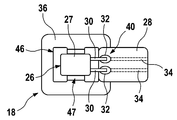
도 2a는 본 발명의 일 실시 예에 따른 전자 모듈(10)용 센서 돔(18)의 종단면도를 도시한다. 도 2b는 도 2a의 센서 돔(18)의 평면도를 도시한다. 2A shows a longitudinal section view of a
센서 요소(26)는 센서 본체(27) 및 적어도 2개의 전기 라인(30)을 포함하고, 상기 전기 라인들은 각각 접촉점(32)에서 도체 포일(28)의 도체 트랙(34)에 전기 전도 방식으로 연결된다. 라인들(32)과 도체 트랙들(34)은 예컨대 납땜되고, 용접되며 및/또는 전도성 접착제에 의해 접착될 수 있다. 이 경우, 도체 포일(28)의 도체 트랙들(34)은 도체 포일(28)의 베이스 층과 커버 층 사이에 수용 및/또는 배치되며, 접촉점들(32)의 영역에서 베이스 층 또는 커버 층은 도체 트랙들(34)과 라인들(32)의 전기적 접촉을 위해 제거될 수 있다. 또한, 도체 트랙들(34)은 변속기 제어 유닛(12) 및/또는 전자 회로(14)에 전기 전도 방식으로 연결될 수 있으며, 도체 포일(28)은 돔 본체(20)로부터 대략 측면으로 돌출할 수 있거나 또는 돔 본체(20)의 플랭크에 놓일 수 있다. The
센서 요소(26) 및/또는 센서 본체(27)는 돔 본체(20)의 제 2 단부(24)에 배치된 지지면(36) 상에 놓이고, 센서 요소(26) 및/또는 센서 본체(27)를 외주에서 둘러싸는 주조 화합물로 오버몰딩된다. 주조 화합물(38)은 열경화성 재료, 열가소성 재료, 에폭시 수지 기반 재료, 실리콘 기반 재료, 폴리우레탄 및/또는 아크릴 접착제를 함유할 수 있다. 주조 화합물(38)은 센서 요소(26)의 적어도 2개의 전기 라인(30) 및 접촉점들(32)을 완전히 둘러싸므로, 라인들(30) 및 접촉점들은 전자 모듈(10) 및/또는 센서 돔(18) 주위로 흐르는 변속기 유체에 대해 밀봉된다. 따라서, 변속기 유체의 칩들, 침적물들 및/또는 도전성 컴포넌트들에 의해 야기될 수 있는, 접촉점들(32) 및/또는 라인들(30) 사이의 단락 및/또는 분로(shunt)가 방지될 수 있다. 또한, 도체 포일(28)의 영역(40)은 주조 화합물(38)로 오버몰딩되고, 상기 영역(40)은 예컨대 주조 화합물(38)과 접촉하는 도체 포일(28)의 일 단부의 면일 수 있다. 상기 면에 대향하는 도체 포일(28)의 단부의 면은 돔 본체(20)의 지지면(36) 상에 놓일 수 있다. 또한, 도체 포일(28)의 단부의 양 면들은 주조 화합물(38)로 오버몰딩될 수 있다. 즉, 지지면(36)과 도체 포일(28) 사이에 주조 화합물(38)이 배치될 수도 있다.The
도 2a에 명확히 나타나는 바와 같이, 주조 화합물(38)은 적어도 부분적으로 매립된 센서 요소(26)와 함께, 돔 본체(20)의 제 2 단부(24)에 배치된 센서 돔(18)의 커버 요소(39)를 형성할 수 있다. 명확화를 위해, 도 2b에는 주조 화합물(38)이 도시되어 있지 않다. 2a, the
바람직하게는, 대략 센서 표면일 수 있는, 센서 요소(26) 및/또는 센서 본체(27)의 외부면(42)은 주조 화합물(38)의 외부면(44)과 동일한 평면으로 끝나므로, 예컨대 홀 센서와 같은 센서 전자 장치들(sensor electronics)이 변속기의 감지될 요소에 가장 가깝게 배치될 수 있다. 즉, 센서 요소(26) 및/또는 센서 본체(27)의 외부면들(42) 사이의 가능한 에어 갭이 플라스틱 층으로 덮인 센서 요소들의 경우보다 크게 형성될 수 있다. 이러한 실시 예는 예컨대, 주조 화합물(38)이 센서 요소(26) 및/또는 센서 본체(27) 또는 센서 요소(26)의 하우징에 접착될 수 있어서, 변속기 유체가 주조 화합물(38)과 센서 요소(26) 사이에 이를 수 없는 경우 바람직할 수 있다. 반면에, 주조 화합물(38)이 센서 요소(26) 또는 그 하우징에 부착되지 않는다면, 센서 요소(26)의 외부면(42)은 주조 화합물(38)로 이루어진 얇은 층으로, 예컨대 0.2 mm의 층 두께로 커버될 수 있다. Preferably, the
돔 본체(20) 상에 또는 돔 본체(20)의 지지면(36) 상에 센서 요소(26)를 포지셔닝하기 위해, 센서 돔(18)은 서로 실질적으로 평행하게 연장하는 한 쌍의 안내 리브(46)를 포함하고, 상기 안내 리브를 따라 센서 요소(26)는 센서 돔(18)의 제조 중에 이동 및/또는 변위될 수 있다. 추가의 공간 방향으로 포지셔닝하기 위해, 센서 돔(18)이 서로 실질적으로 평행하게 연장하는 추가 쌍의 안내 리브(47)를 포함하므로, 센서 요소(26)가 2개의 서로 직교하는 공간 방향들로 지지면(36) 상에 포지셔닝될 수 있다. 센서 요소(26)의 적어도 하나의 부분 영역은 안내 웨브들(46, 47) 중 하나의 안내 웨브의 적어도 하나의 부분 영역에 그 포지셔닝을 위해 놓일 수 있다. 안내 웨브(47) 및/또는 안내 웨브(46)는 적어도 부분 영역에서 예컨대 지지면(36)의 오목부 또는 돌출부로서 형성될 수 있다.In order to position the
또한, 센서 돔(18) 및/또는 돔 본체(20)는 돔 본체(20)의 길이 방향으로 지지면(36)을 통해 연장되는 적어도 하나의 리세스(49)를 포함하며, 상기 리세스(49)는 관통구라고 할 수 있다. 예컨대, 돔 본체(20)는 2개의 리세스(49)를 포함하며, 안내 웨브들(46, 47)의 적어도 일부는 각각 리세스(49)의 부분 영역, 예컨대 리세스(49)의 에지 및/또는 가장자리에 의해 형성될 수 있다. 리세스(49)는 주조 화합물(38)로 적어도 부분적으로 채워지거나 및/또는 분무될 수 있는, 지지면(36)을 관통하는 관통구로서 형성될 수 있다. 바람직하게는, 리세스(49)가 주조 화합물(38)로 완전히 충전된다. 따라서, 돔 본체(20)의 내부 체적 중 적어도 하나의 부분 영역은 주조 화합물(38)로 분무될 수 있고, 주조 화합물(38)은 돔 본체(20), 예컨대 돔 본체(20) 및/또는 리세스(49)에 의해 형성된 적어도 하나의 언더컷(20)에 형상 끼워 맞춤 방식으로 고정될 수 있다. 결과적으로, 주조 화합물(38) 및 그 안에 적어도 부분적으로 수용된 센서 요소(26)가 돔 본체에 확실하게 고정될 수 있다. 주조 화합물(38) 및 돔 본체(20)의 재료에 따라, 주조 화합물(38)은 돔 본체(20)에 재료 결합 방식으로 연결될 수 있다.The
도 2a 및 도 2b에 도시된 센서 돔(18)을 제조하기 위해, 센서 요소(26)는 접촉점들(32)에 연결된 도체 포일(28)과 함께 지지면(36) 상에 놓일 수 있고, 센서 요소(26)의 외부면(42)에 놓일 수 있는 공구에 의해 센서 요소(26)는 지지면(36)의 방향으로 지지될 수 있다. 돔 본체(20)의 제 1 단부(22)를 통해, 펀치 공구가 돔 본체의 내부 용적 내로 이동될 수 있어서, 주조 화합물(38)로 충전, 분무 및/또는 성형될 수 있는 캐비티가 형성될 수 있다. 대안으로서, 센서 요소(26)를 갖는 돔 본체(20)가 장치 내에 배치될 수 있고, 주조 화합물(38)이 돔 본체(20)의 내부 용적 내로 충전됨으로써, 주조 화합물(38)이 지구 중력장에서 유지된다.To fabricate the
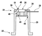
도 3a는 본 발명의 일 실시 예에 따른 전자 모듈(10)용 센서 돔(18)의 종단면도를 도시한다. 도 3b는 도 3A의 센서 돔(18)의 평면도를 도시한다. 다른 설명이 없는 한, 도 3a 및 도 3b의 센서 돔들(18)은 이전 도면들에서 설명된 센서 돔(18)과 동일한 요소들 및 특징들을 포함할 수 있다.Figure 3a shows a longitudinal section view of a
도 3a 및 도 3b에 도시된 실시 예들의 경우, 돔 본체(20)의 길이 방향으로 지지면(36)으로부터 돌출하는 정지 요소(51)가 안내 웨브들(46) 중 하나의 안내 웨브의 영역에 형성된다. 센서 요소(26)를 지지면(36) 상에 포지셔닝하기 위해, 센서 요소(26)의 적어도 하나의 부분 영역, 예컨대 플랭크가 상기 정지 요소(51)에 접촉할 수 있다. 정지 요소(51)는 주조 화합물(38)로 적어도 부분적으로, 바람직하게는 완전하게 오버몰딩될 수 있다. 정지 요소(51)의 표면은 주조 화합물(38)로부터 돌출하거나 또는 주조 화합물(38)로 커버될 수 있다. 다수의 이러한 정지 요소들(51)이 센서 돔(18) 상에 형성될 수도 있다.3A and 3B, a
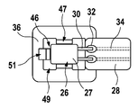
도 4a는 본 발명의 일 실시 예에 따른 전자 모듈(10)용 센서 돔(18)의 종단면도를 도시한다. 도 4b 및 도 4c는 각각 본 발명의 실시예에 따른 도 4a의 센서 돔의 평면도를 도시한다. 주조 화합물(38)은 명확화를 위해 도 4b 및 도 4c에 도시되어 있지 않다. 다른 설명이 없는 한, 도 4a 내지 도 4c의 센서 돔들(18)은 이전 도면들에서 설명된 센서 돔(18)과 동일한 요소들 및 특징들을 포함할 수 있다.4a shows a longitudinal section view of a
도 4a 내지 도 4c에 도시된 실시 예들에서, 도체 포일(28)은 센서 리세스(50)를 포함하며, 상기 센서 리세스 내에서 센서 요소(26)의 센서 본체(27)는 도체 포일(28)의 부분 영역(52)이 센서 본체(27)의 외주 상에서 센서 본체(27)를 둘러싸도록 배치된다. 센서 리세스(50)는 도체 포일(28) 내로 펀칭된 구멍일 수 있고 및/또는 센서 리세스(50)는 주조 화합물(38)로 적어도 부분적으로, 바람직하게는 완전히 채워질 수 있다. 돔 본체(20) 상에 및/또는 돔 본체(20)의 지지면(36) 상에 센서 요소(26)를 포지셔닝하기 위해, 도체 포일(28)의 적어도 하나의 가장자리 또는 외부 에지(54)는 지지면(36) 및/또는 돔 본체(20)의 외부 에지(56)와 동일 평면으로 끝날 수 있다.4A-4C, the
도 4c에 도시된 바와 같이, 센서 본체(27)를 둘러싸는 도체 포일(28)의 부분 영역(52)은 실질적으로 지지면(36)의 형상 또는 윤곽을 가질 수 있어서, 도체 포일(28)의 다수의 가장자리들 또는 외부 에지들(54), 예컨대 2개 또는 3개의 외부 에지들(54)이 지지면(36) 및/또는 돔 본체(20)의 외부 에지(56)와 동일 평면으로 끝날 수 있다. 이러한 방식으로, 센서 요소(26)는 높은 정확도로 돔 본체(20)의 지지면(36) 상에 2개의 서로 직교하는 공간 방향으로 포지셔닝될 수 있고, 후속해서 주조 화합물(38)로 고정 및/또는 보호될 수 있다.4C, the
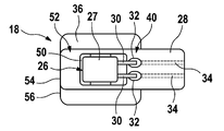
도 5는 본 발명의 일 실시 예에 따른 전자 모듈(10)용 센서 돔(18)의 평면도를 도시하며, 주조 화합물(38)은 명료화를 위해 도 5에 도시되어 있지 않다. 다른 설명이 없는 한, 도 5의 센서 돔(18)은 이전의 도면들에서 설명된 센서 돔들(18)과 동일한 요소들 및 특징들을 포함할 수 있다.Figure 5 shows a top view of a
도 5에 도시된 실시 예에서, 도체 포일(28)은 도체 포일(28)의 도체 트랙들 (34) 사이에 및/또는 접촉점들(32) 사이에 배치된 리세스(58)를 포함하며, 이 리세스는 도체 포일(28) 내로 펀칭된 구멍으로서 형성될 수 있다. 5, the
리세스(58)는 도 5에서 센서 리세스(50)와 별개로 도시되어 있다. 대안으로서, 리세스(58)는 센서 리세스(50)와 함께 연속하는 리세스를 형성할 수 있다.The
접촉점들(32) 사이에 배치된 리세스(58)는 주조 화합물(38)로 적어도 부분적으로 채워지고 및/또는 분무된다. 바람직하게, 리세스(58)는 주조 화합물(38)로 완전히 충전 및/또는 분무된다. 한편으로, 도체 포일(28)은 주조 화합물(38) 내에 고정될 수 있고, 다른 한편으로는 리세스(58) 내에 배치된 주조 화합물(38)은 라인들(30) 및/또는 접촉점들 및/또는 도체 트랙들(34) 사이의 배리어를 제공할 수 있고, 상기 배리어에 의해 단락 및/또는 분로가 방지될 수 있다. 즉, 라인들(30), 접촉점들(32) 및/또는 도체 트랙들(34)은 주조 화합물(38)에 의해 분리될 수 있으므로, 도체 포일(28)의 표면 위의 도전성 침적물들(Cu 부식), 칩들 및/또는 전자 이동 등에 의한 전기적 연결이 형성될 수 없다.The
도 6은 본 발명의 일 실시예에 따른 전자 모듈(10)용 센서 돔(18)의 종단면도를 도시한다. 다른 설명이 없는 한, 도 6의 센서 돔(18)은 이전 도면들에서 설명된 센서 돔(18)과 동일한 요소들 및 특징들을 포함할 수 있다.Figure 6 shows a longitudinal section view of a
도 6에 도시된 실시 예에서, 센서 본체(27) 및/또는 센서 요소(26)의 외부면(42)은 주조 화합물(38)로 이루어진 층(45)으로 커버된다. 상기 층(45)은 2mm 미만, 예컨대 1mm 미만의 두께를 가진다. 바람직하게, 상기 층(45)은 약 0.3mm 내지 0.6 mm의 두께를 갖는다.6, the
제조 공정의 결과로서 층(45) 내에 리세스(60)가 배치될 수 있는데, 상기 리세스(60)는 센서 본체(27)가 주조 화합물(38) 내에서 부유하는 것을 방지하기 위해 센서 본체(27)가 제조 중에 플런저에 의해 지지면(36) 상에 지지됨으로써 형성될 수 있다.A
또한, 도체 포일(28)은 돔 본체(20)의 측면에서 아래로 접혀서, 적어도 부분 영역에서 돔 본체(20)의 플랭크에 놓인다. 도체 포일(28)은 돔 본체(20)의 플랭크에 고정 장치(62)에 의해, 예컨대 추가로 핫 리벳팅될 수 있는 센서 돔(18) 또는 돔 본체(20) 상의 핀에 꿰는 것을 통해 고정될 수 있다.In addition, the
도 7은 본 발명의 일 실시 예에 따른 전자 모듈(10)용 센서 돔(18)의 종단면도를 도시한다. 다른 설명이 없는 한, 도 7의 센서 돔(18)은 이전 도면들에서 설명된 센서 돔(18)과 동일한 요소들 및 특징들을 포함할 수 있다.Figure 7 shows a longitudinal section view of a
도 7의 센서 돔(18)은 센서 요소(26)의 외부면(42)을 적어도 부분적으로 커버하는 단부 캡(64)을 포함한다. 단부 캡(64)은 플라스틱 성형 부품일 수 있다. 센서 돔(18)의 제조를 위해, 단부 캡(64)은 공구의 형태로 삽입되거나 센서 요소(26) 상에 배치될 수 있고, 센서 돔(18)은 단부 캡(64)과 함께 포지셔닝될 수 있어서, 주조 화합물(38)이 센서 돔(18)의 제 1 단부(22)를 통해 돔 본체의 내부 용적(29) 내로 도입될 수 있다. 주조 화합물(38)이 공구에 접착되는 것을 방지하고 센서 요소(26)를 보호하기 위해, 단부 캡(64)은 센서 돔(18) 상에 남아 있을 수 있다.The
도 8은 본 발명의 일 실시 예에 따른 전자 모듈(10)용 센서 돔(18)의 종단면도를 도시한다. 다른 설명이 없는 한, 도 8의 센서 돔(18)은 이전 도면들에서 설명된 센서 돔(18)과 동일한 요소들 및 특징들을 포함할 수 있다.8 shows a longitudinal section view of a
도 8에 도시된 실시 예에서, 외부면(42)은 돔 본체(20)의 지지면(36)과 동일 평면으로 끝난다. 이를 위해, 센서 본체(27)는 주조 화합물(38)로 적어도 부분적으로, 바람직하게는 완전히 충전 및/또는 분무되는, 돔 본체(20)의 오목부(66) 내에 수용된다.In the embodiment shown in FIG. 8, the
센서 돔(18)을 제조하기 위해, 센서 요소(26) 및/또는 센서 본체(27)는 오목부(66) 내로 삽입될 수 있으며 공구 펀치는 단부(22)를 통해 돔 본체(20)의 내부 용적 내로 이동될 수 있다. 단부(24)로부터 주조 화합물(38)이 주입될 수 있고 및/또는 센서 요소(26)가 주조 또는 성형될 수 있다. 주조 화합물(38)이 삽입되는 동안, 도체 포일(28)이 측면으로 도출될 수 있고 돔 본체(20)와 공구 사이에 고정될 수 있기 때문에, 도체 포일(28)의 두께 및 폭은 매우 작은 치수 변동으로 제조될 수 있다.The
끝으로, "갖는", "포함하는" 등의 표현들은 다른 요소들 또는 단계들을 배제하지 않으며 "a" 또는 "an" 등의 표현들은 다수를 배제하지 않는다. 청구 범위에서의 도면 부호들은 제한으로서 간주되어서는 안된다.Finally, the expressions "having", "including" and the like do not exclude other elements or steps, and expressions such as "a" or "an" do not exclude the majority. The reference signs in the claims should not be construed as limitations.
10 : 전자 모듈
12 : 변속기 제어 유닛
14 : 전자 회로
18 : 센서 돔
20 : 돔 본체
26 : 센서 요소
28 : 도체 포일
30 : 전기 라인
32 : 접촉점
34 : 도체 트랙
36 : 지지면
38 : 주조 화합물
50 : 센서 리세스10: Electronic module
12: Transmission control unit
14: Electronic circuit
18: Sensor dome
20: Dome body
26: Sensor element
28: Conductor foil
30: Electric line
32: contact point
34: Conductor track
36: Support surface
38: casting compound
50: Sensor recess
Claims (10)
적어도 하나의 캐리어 요소(16); 및
적어도 하나의 센서 돔(18)을 포함하는, 자동차의 변속기 제어 장치용 전자 모듈(10)로서,
상기 센서 돔은 길게 형성된 돔 본체(20)를 포함하고, 상기 돔 본체(20)의 제 1 단부(22)는 캐리어 요소(16) 상에 배치되며, 상기 돔 본체(20)는 상기 캐리어 요소로부터 돌출하고,
상기 센서 돔은 상기 제 1 단부에 대향하는 제 2 단부(24)에 전자 센서 요소(26)를 포함하며, 상기 전자 센서 요소(26)는 적어도 2개의 전기 라인(30)을 포함하고, 상기 전기 라인들은 각각 접촉점(32)에서 커버 층과 베이스 층 사이에 배치된 도체 포일(28)의 도체 트랙(34)에 전기 전도 방식으로 연결되며,
상기 도체 포일의 상기 도체 트랙들은 각각 상기 변속기 제어 유닛의 상기 전자 회로에 전기 전도 방식으로 연결되고,
상기 센서 요소는 적어도 상기 센서 요소의 외주에서 상기 센서 요소를 완전히 둘러싸는 주조 화합물(38)로 오버몰딩되는, 상기 전자 모듈(10)에 있어서,
상기 센서 요소의 상기 적어도 2개의 전기 라인들, 상기 접촉점들 및 상기 도체 포일의 영역(40)은 상기 전기 라인들 및 접촉점들이 상기 주조 화합물에 의해 서로 분리되도록, 상기 주조 화합물에 의해 오버몰딩되는 것을 특징으로 하는 전자 모듈(10).A transmission control unit (12) having an electronic circuit (14);
At least one carrier element (16); And
An electronic module (10) for a transmission control device of a vehicle, comprising at least one sensor dome (18)
Wherein the sensor dome comprises a elongated dome body 20 and a first end 22 of the dome body 20 is disposed on a carrier element 16 and the dome body 20 extends from the carrier element Protruding,
The sensor dome includes an electronic sensor element (26) at a second end (24) opposite the first end, the electronic sensor element (26) comprising at least two electrical lines (30) The lines are each electrically conductively connected to a conductor track 34 of a conductor foil 28 disposed between the cover layer and the base layer at a contact point 32,
Each of the conductor tracks of the conductor foil being electrically conductively connected to the electronic circuit of the transmission control unit,
Wherein the sensor element is overmolded with at least a casting compound (38) that completely surrounds the sensor element at the periphery of the sensor element,
The at least two electrical lines of the sensor element, the contact points and the area of the conductor foil (40) are such that the electrical lines and contact points are overmolded by the casting compound so that they are separated from each other by the casting compound (10).
상기 리세스(58)는 상기 접촉점들 사이에서 적어도 부분적으로 상기 주조 화합물(38)로 충전되는 것을 특징으로 하는 전자 모듈(10).5. A method according to any one of claims 1 to 4, wherein the conductor foil comprises a recess (58) between the contact points (32)
Characterized in that the recess (58) is filled at least partially between the contact points with the casting compound (38).
상기 센서 돔(18)은 상기 센서 요소의 상기 외부면(42)을 적어도 부분적으로 커버하는 단부 캡(54)을 포함하는 것을 특징으로 하는 전자 모듈(10).9. A sensor element according to any one of the preceding claims, wherein the outer surface (42) of the sensor element is covered by a layer (45) of a casting compound, the layer has a layer thickness of up to 2 mm and / or
Characterized in that the sensor dome (18) comprises an end cap (54) at least partially covering the outer surface (42) of the sensor element.
Applications Claiming Priority (3)
| Application Number | Priority Date | Filing Date | Title |
|---|---|---|---|
| DE102015207873.6A DE102015207873A1 (en) | 2015-04-29 | 2015-04-29 | Electronic module for a gearbox control unit |
| DE102015207873.6 | 2015-04-29 | ||
| PCT/EP2016/054362 WO2016173746A1 (en) | 2015-04-29 | 2016-03-02 | Electronics module for a transmission control unit |
Publications (1)
| Publication Number | Publication Date |
|---|---|
| KR20170140233A true KR20170140233A (en) | 2017-12-20 |
Family
ID=55453163
Family Applications (1)
| Application Number | Title | Priority Date | Filing Date |
|---|---|---|---|
| KR1020177030978A KR20170140233A (en) | 2015-04-29 | 2016-03-02 | Electronic modules for transmission control devices |
Country Status (5)
| Country | Link |
|---|---|
| EP (1) | EP3289840B1 (en) |
| KR (1) | KR20170140233A (en) |
| CN (1) | CN107535059B (en) |
| DE (1) | DE102015207873A1 (en) |
| WO (1) | WO2016173746A1 (en) |
Families Citing this family (3)
| Publication number | Priority date | Publication date | Assignee | Title |
|---|---|---|---|---|
| DE102015219005A1 (en) | 2015-10-01 | 2017-04-06 | Robert Bosch Gmbh | Electronic module, in particular for transmission control, with sensor connection by means of flexible conductor foil positioned via centering pins |
| DE102017209179A1 (en) * | 2017-05-31 | 2018-12-06 | Conti Temic Microelectronic Gmbh | electronics assembly |
| DE102018211503A1 (en) * | 2018-07-11 | 2020-01-16 | Robert Bosch Gmbh | Method and measuring head |
Family Cites Families (2)
| Publication number | Priority date | Publication date | Assignee | Title |
|---|---|---|---|---|
| DE10110620A1 (en) | 2001-03-06 | 2002-09-26 | Conti Temic Microelectronic | Electronic assembly |
| DE102008043169A1 (en) * | 2008-10-24 | 2010-04-29 | Endress + Hauser Gmbh + Co. Kg | Measuring device and method for producing the measuring device |
-
2015
- 2015-04-29 DE DE102015207873.6A patent/DE102015207873A1/en not_active Withdrawn
-
2016
- 2016-03-02 KR KR1020177030978A patent/KR20170140233A/en unknown
- 2016-03-02 CN CN201680024498.2A patent/CN107535059B/en not_active Expired - Fee Related
- 2016-03-02 EP EP16707727.0A patent/EP3289840B1/en active Active
- 2016-03-02 WO PCT/EP2016/054362 patent/WO2016173746A1/en active Application Filing
Also Published As
| Publication number | Publication date |
|---|---|
| EP3289840A1 (en) | 2018-03-07 |
| CN107535059B (en) | 2019-12-10 |
| DE102015207873A1 (en) | 2016-11-03 |
| CN107535059A (en) | 2018-01-02 |
| WO2016173746A1 (en) | 2016-11-03 |
| EP3289840B1 (en) | 2020-12-16 |
Similar Documents
| Publication | Publication Date | Title |
|---|---|---|
| CN107926120B (en) | Electronic device module with components that can be flexibly placed via socket elements and method for manufacturing the same | |
| US8035208B2 (en) | Integrated circuit package | |
| KR20130128410A (en) | Control module and method for producing same | |
| US10964623B2 (en) | Electronic module and method for encapsulation thereof | |
| KR20170140233A (en) | Electronic modules for transmission control devices | |
| CN107954393B (en) | Sensor with single electric support | |
| CN108139239B (en) | Method for producing a sensor arrangement for a transmission control device | |
| KR20180002651A (en) | Electrical connection device | |
| KR20170048359A (en) | Module assembly and transmission control module | |
| KR100788858B1 (en) | Structure and assembly method of integrated circuit package | |
| CN107006126A (en) | Utilize the electronic apparatus module particularly for automotive drive control device of face contact sandwich building block technique | |
| CN107079583B (en) | Transmission control module for use in contaminated media, TCU assembly for use in such a transmission control module, and method for manufacturing such a transmission control module | |
| JP4864742B2 (en) | Modular equipment | |
| CN107660089B (en) | Electronic controller with laser welding sealed housing | |
| CN109219246B (en) | Packaged integrated circuit component | |
| US7791891B2 (en) | Enclosure including an electrical module | |
| WO2014208080A1 (en) | Electronic apparatus | |
| CN107295741B (en) | Electronic unit with ESD protection device | |
| JP2012129306A (en) | Electronic apparatus | |
| JP5392243B2 (en) | Electronic device and manufacturing method thereof | |
| EP2996145B1 (en) | Inter-connection of a lead frame with a passive component intermediate structure | |
| JP5384883B2 (en) | Electronic hydraulic control module | |
| JP2012129305A (en) | Electronic apparatus | |
| JP6149982B2 (en) | Electronic equipment | |
| KR20170138433A (en) | Electronic modules for transmission control devices |