KR20170139934A - Structure of drive-shaft - Google Patents
Structure of drive-shaft Download PDFInfo
- Publication number
- KR20170139934A KR20170139934A KR1020160072568A KR20160072568A KR20170139934A KR 20170139934 A KR20170139934 A KR 20170139934A KR 1020160072568 A KR1020160072568 A KR 1020160072568A KR 20160072568 A KR20160072568 A KR 20160072568A KR 20170139934 A KR20170139934 A KR 20170139934A
- Authority
- KR
- South Korea
- Prior art keywords
- race
- cage
- ball
- inner race
- shape
- Prior art date
Links
Images


Classifications
-
- F—MECHANICAL ENGINEERING; LIGHTING; HEATING; WEAPONS; BLASTING
- F16—ENGINEERING ELEMENTS AND UNITS; GENERAL MEASURES FOR PRODUCING AND MAINTAINING EFFECTIVE FUNCTIONING OF MACHINES OR INSTALLATIONS; THERMAL INSULATION IN GENERAL
- F16D—COUPLINGS FOR TRANSMITTING ROTATION; CLUTCHES; BRAKES
- F16D3/00—Yielding couplings, i.e. with means permitting movement between the connected parts during the drive
- F16D3/16—Universal joints in which flexibility is produced by means of pivots or sliding or rolling connecting parts
- F16D3/20—Universal joints in which flexibility is produced by means of pivots or sliding or rolling connecting parts one coupling part entering a sleeve of the other coupling part and connected thereto by sliding or rolling members
- F16D3/22—Universal joints in which flexibility is produced by means of pivots or sliding or rolling connecting parts one coupling part entering a sleeve of the other coupling part and connected thereto by sliding or rolling members the rolling members being balls, rollers, or the like, guided in grooves or sockets in both coupling parts
-
- F—MECHANICAL ENGINEERING; LIGHTING; HEATING; WEAPONS; BLASTING
- F16—ENGINEERING ELEMENTS AND UNITS; GENERAL MEASURES FOR PRODUCING AND MAINTAINING EFFECTIVE FUNCTIONING OF MACHINES OR INSTALLATIONS; THERMAL INSULATION IN GENERAL
- F16C—SHAFTS; FLEXIBLE SHAFTS; ELEMENTS OR CRANKSHAFT MECHANISMS; ROTARY BODIES OTHER THAN GEARING ELEMENTS; BEARINGS
- F16C33/00—Parts of bearings; Special methods for making bearings or parts thereof
- F16C33/30—Parts of ball or roller bearings
- F16C33/38—Ball cages
- F16C33/3837—Massive or moulded cages having cage pockets surrounding the balls, e.g. machined window cages
- F16C33/3843—Massive or moulded cages having cage pockets surrounding the balls, e.g. machined window cages formed as one-piece cages, i.e. monoblock cages
-
- F—MECHANICAL ENGINEERING; LIGHTING; HEATING; WEAPONS; BLASTING
- F16—ENGINEERING ELEMENTS AND UNITS; GENERAL MEASURES FOR PRODUCING AND MAINTAINING EFFECTIVE FUNCTIONING OF MACHINES OR INSTALLATIONS; THERMAL INSULATION IN GENERAL
- F16C—SHAFTS; FLEXIBLE SHAFTS; ELEMENTS OR CRANKSHAFT MECHANISMS; ROTARY BODIES OTHER THAN GEARING ELEMENTS; BEARINGS
- F16C2208/00—Plastics; Synthetic resins, e.g. rubbers
- F16C2208/20—Thermoplastic resins
-
- F—MECHANICAL ENGINEERING; LIGHTING; HEATING; WEAPONS; BLASTING
- F16—ENGINEERING ELEMENTS AND UNITS; GENERAL MEASURES FOR PRODUCING AND MAINTAINING EFFECTIVE FUNCTIONING OF MACHINES OR INSTALLATIONS; THERMAL INSULATION IN GENERAL
- F16D—COUPLINGS FOR TRANSMITTING ROTATION; CLUTCHES; BRAKES
- F16D3/00—Yielding couplings, i.e. with means permitting movement between the connected parts during the drive
- F16D3/16—Universal joints in which flexibility is produced by means of pivots or sliding or rolling connecting parts
- F16D3/20—Universal joints in which flexibility is produced by means of pivots or sliding or rolling connecting parts one coupling part entering a sleeve of the other coupling part and connected thereto by sliding or rolling members
- F16D3/22—Universal joints in which flexibility is produced by means of pivots or sliding or rolling connecting parts one coupling part entering a sleeve of the other coupling part and connected thereto by sliding or rolling members the rolling members being balls, rollers, or the like, guided in grooves or sockets in both coupling parts
- F16D3/223—Universal joints in which flexibility is produced by means of pivots or sliding or rolling connecting parts one coupling part entering a sleeve of the other coupling part and connected thereto by sliding or rolling members the rolling members being balls, rollers, or the like, guided in grooves or sockets in both coupling parts the rolling members being guided in grooves in both coupling parts
- F16D2003/22303—Details of ball cages
Landscapes
- Engineering & Computer Science (AREA)
- General Engineering & Computer Science (AREA)
- Mechanical Engineering (AREA)
- Rolling Contact Bearings (AREA)
Abstract
Description
본 발명은 종래의 구조 대비 마찰력을 저감시킬 수 있는 드라이브샤프트의 구조에 관한 것으로써, 더욱 상세하게는 볼과의 접촉면적을 줄일 수 있고 자기 윤활성을 갖는 케이지를 구비하여 마찰저항에 따른 에너지 손실을 방지할 수 있는 드라이브샤프트의 구조에 관한 것이다.The present invention relates to a structure of a drive shaft capable of reducing a frictional force compared with a conventional structure, and more particularly, to a structure of a drive shaft capable of reducing a contact area with a ball and having a cage having self- And more particularly to a structure of a drive shaft.
드라이브샤프트는 트랜스미션(또는 디퍼련셜기어박스나 트랜스퍼케이스)과 휠을 연결하여 엔진에서 생성된 구동력을 휠로 전달하되, 차량의 선회시 양측의 각속도의 변화없이 회전력을 전달할 수 있는 자재 이음(universal joint)로써 등속 조인트(constant velocity joint)라고도 불린다.The drive shaft connects a transmission (or a differential gear box or transfer case) to a wheel to transmit the driving force generated by the engine to the wheel. It is a universal joint that can transmit the rotational force without changing the angular speed of both sides when the vehicle is turning. It is also called a constant velocity joint.
이와 같은 드라이브샤프트는 여러가지 타입이 상용화된 바 있으나, 이중 크로스 그루브 조인트(CROSS GROOVE JOINT)는 도 1, 2 에 도시된 바와 같이, 일단은 휠이나 트랜스미션(또는 디퍼련셜기어박스나 트랜스퍼케이스) 중 어느 한 쪽으로 연결되고 타단에는 이너레이스(11)가 장착된 제1샤프트(10)와 일단은 휠이나 트랜스미션 중 다른 한 쪽으로 연결되고 타단에는 이너레이스(11)가 내부로 진입가능하도록 컵모양의 아우터레이스(21)가 형성된 제2샤프트(20)와 상기 이너레이스(11)의 외주면에 형성된 내측구속홈들(12)과 아우터레이스(21)의 내주면에 형성된 외측구속홈들(22) 사이에서 구름운동이 가능하게 장착되는 다수 개의 볼(30) 및 각각의 볼들(30)이 놓이는 다수 개의 안착홀들(41)이 둘레를 따라 형성되며, 이너레이스(11)와 아우터레이스(21) 사이에 장착되어 볼(30)의 이탈을 방지하는 케이지(40)를 포함한다.Various types of such drive shafts have been commercialized. However, as shown in FIGS. 1 and 2, a double cross groove joint may be formed at one end of a wheel or a transmission (or a differential gear box or a transfer case) A
즉, 아우터레이스(21)는 트랜스미션으로부터 전달받은 구동력을 볼(30)에 전달하고, 상기 볼(30)은 이너레이스(11)의 내측구속홈들(12)과 아우터레이스(21)의 외측구속홈들(22) 사이에서 구동력을 전달하며 내측구속홈들(12)과 외측구속홈들(22)을 활주하여 작동각을 확보할 수 있다. 이때, 케이지(40)는 볼(30)의 이탈을 방지함과 동시에 이너레이스(11)의 축 방향 및 반경방향의 위치를 규제하는 기능을 한다.That is, the
그러나, 상기 케이지(40)는 볼(30) 위치를 유지시키며 원활한 구름 운동이 이뤄지도록 가이드 역할을 하나 볼(30)과의 상시 접촉으로 마찰력을 발생시켜 에너지의 손실을 유발한다. However, the
이러한 종래 구조의 문제점을 더 상세히 살펴보면, 첫째로 종래의 케이지(40)는 금속재로 제조되어 프레스 또는 주물을 통해 제조된 후 2차 가공이 추가적으로 요구되었었다. 이에 따라, 두께 및 형상 변경이 어려웠으며, 형상의 변경이 필요할 때 추가적인 가공이 요구되어 제품 단가가 상승하고 품질 편차가 발생하여 일정한 특성을 유지하기 어려웠다(이는 제품 성능 큰 영향 미쳐 소음, 진동을 유발할 수 있었다).First, the
그리고, 구름저항 감소를 위해 케이지(40)와 볼(30)의 표면처리를 추가하면 원가 상승 및 내구성에 문제가 발생할 가능성이 있었으며, 무엇보다도 케이지(40)와 볼(30) 모두는 금속재로 제조되어 안착홀(41)의 내주면(41a)에 접촉 시(도 3 참조) 진동 및 이음을 발생시킬 가능성이 증대되었고 이는 볼(30)의 구름 저항(마찰력)을 증가시켜 연비에 악영향을 미칠 수 있었다.Further, if the surface treatment of the
따라서, 본 발명은 2차가공이 요구되지 않고 사출성형을 통해 용이하게 형상 제작이 가능한 고분자재료(예를 들면, 열가소성 엔지니어링 플라스틱 등)로 케이지가 제작되어, 볼과 케이지 사이에서 마찰력을 현저히 감소시킴으로써 상기와 같은 종래 구조의 문제점을 원천적으로 해소할 수 있는 드라이브샤프트의 구조를 제공하는 것에 주목적이 있다. Therefore, the present invention is based on the fact that the cage is made of a polymeric material (e.g., thermoplastic engineering plastic, etc.) that can be easily shaped through injection molding without requiring secondary processing, thereby significantly reducing the frictional force between the ball and the cage It is a main object of the present invention to provide a structure of a drive shaft that can solve the problems of the conventional structure as described above.
전술한 바와 같은 목적을 달성하기 위한 본 발명은, (일측 끝단은 휠 또는 트랜스미션 중 어느 쪽으로 연결되되 반대쪽의) 끝단에 이너레이스가 장착된 제1샤프트;와 (일측 끝단은 휠 또는 트랜스미션 중 나머지 다른 한쪽으로 연결되되 반대쪽의) 끝단에서 이너레이스가 내부로 진입가능하도록 컵모양의 아우터레이스가 형성된 제2샤프트;와 상기 이너레이스의 외주면에 형성된 내측구속홈들과 아우터레이스의 내주면에 형성된 외측구속홈들 사이에서 구름운동이 가능하게 장착되는 다수 개의 볼; 및 각각의 볼들이 놓이는 다수 개의 안착홀들이 둘레를 따라 형성되며, 이너레이스와 아우터레이스 사이에 장착되어 볼의 이탈을 방지하는 케이지;를 포함하고, 상기 케이지는 고분자재료로 제조된 것을 특징으로 한다.In order to achieve the above-mentioned object, the present invention provides a vehicle comprising: a first shaft having an inner race mounted on an end of a vehicle (one end connected to either a wheel or a transmission but opposite) A second shaft connected to one end of the inner race and formed with a cup-like outer race so that the inner race can enter the inside of the inner race, and an inner limiting groove formed on the outer peripheral surface of the inner race and an outer limiting groove formed on an inner peripheral surface of the outer race, A plurality of balls on which rolling motions are possible to be mounted; And a cage formed between the inner race and the outer race to prevent the balls from coming off, wherein the cage is made of a polymeric material .
상기 케이지는 금속재인 볼과 접촉시 마찰계수가 0.4 이하가 되는 자기 윤활성(self-lubricative)을 갖는 고분자재료 예를 들어, 열가소성수지(thermoplastic resin)로 제조된다.The cage is made of a thermoplastic resin such as a self-lubricating polymeric material having a coefficient of friction of 0.4 or less on contact with a metal ball.
아울러, 본 발명에서는 볼을 지지할 때 마찰력을 추가적으로 감소시킬 수 있도록(볼과의 접촉면적을 줄일 수 있도록) 상기 안착홀 내주면(볼이 맞닿는 면)의 어느 한쪽은 볼을 향하는 끝단쪽으로 갈수록 두께가 좁아지는 모양(가령, '▶' 와 같이 끝단이 뾰족한 단면을 갖는 모양 또는 사다리꼴 단면을 갖는 모양 등)을 갖거나, 상기 안착홀 내주면의 어느 한쪽은 볼을 향하는 끝단이 호형(弧形)으로 볼록하게 형성된 모양(즉, '⊃' 와 같은 단면을 갖는 모양 등)을 갖는다.In addition, in the present invention, either one of the inner circumferential surface of the mounting hole (the surface on which the balls come into contact with each other) becomes thicker toward the end toward the ball so as to further reduce the frictional force when supporting the ball (For example, a shape having a pointed end or a trapezoidal cross-sectional shape such as a cross-sectional shape such as a cross-sectional shape such as a cross-sectional shape such as a cross-sectional shape), or one of the inner circumferential surfaces of the placement hole has a convex- (That is, a shape having a cross section such as '⊃', etc.).
또한, 선택적 실시예로써, 상기 안착홀 내주면의 어느 한쪽의 모양과 볼을 사이에 두고 다른 한쪽의 모양은 서로 다르게 형성될 수도 있다.Also, as an alternative embodiment, the shape of either one of the inner circumferential surfaces of the mounting holes may be different from the shape of the other one with the ball interposed therebetween.
상기와 같은 구성을 갖는 본 발명은 케이지가 고분자재료로 제조되어 사출성형 등과 같은 방식으로 제조가능하므로 형상변경이 필요할 때 용이하게 대처할 수 있으며, 다양한 형상 및 치수를 갖도록 제작이 가능하다(즉, 종래의 금속재 케이지 보다 훨씬 용이하게 제조가 가능하며 중량을 저감할 수 있다).Since the cage is made of a polymer material and can be manufactured by a method such as injection molding or the like, the cage can be easily handled when the shape change is required, and can be manufactured to have various shapes and dimensions (i.e., The metal cage can be manufactured much easier and the weight can be reduced).
아울러, 본 발명의 고분자재료는 자기윤활성을 가짐에 따라 추가적인 표면처리가 불필요하며 윤활제의 사용을 줄일 수 있고, 마찰력을 최소화하여 소음 및 진동 발생을 억제할 수 있다.In addition, since the polymer material of the present invention has self-lubricating property, additional surface treatment is unnecessary, use of the lubricant can be reduced, friction can be minimized, and noise and vibration can be suppressed.
또한, 본 발명에서는 안착홀 내주면은 볼을 향하는 끝단쪽으로 갈수록 두께가 좁아지는 모양을 갖거나 또는 볼을 향하는 끝단이 호형(弧形)으로 볼록하게 형성되어 (종래의 구조에서는 볼이 면접촉하던 구성과는 다르게) 볼과 선접촉하게 되므로 접촉면적을 줄여 마찰력을 더욱 감소시킬 수 있다.In addition, in the present invention, the inner circumferential surface of the mounting hole has a shape in which the thickness becomes narrower toward the end toward the ball, or an end toward the ball is convex in an arcuate shape (in the conventional structure, The contact area is reduced and the frictional force can be further reduced.
참고적으로, 본 발명에서는 케이지가 고분자재료(예를 들어, 열가소성 엔지니어링 플라스틱)로 제조됨에 따라 케이지에 작용하는 (좌우, 전후, 상하 방향의) 비틀림력에 대한 연성 및 복원력이 종래의 금속재 보다 증가하여 충격 및 외력을 탄력적으로 수용할 수 있으므로 내구성을 증대할 수 있고, 사출 성형 후 바로 사용가능하므로 생산원가를 절감시킬 수 있다. For reference, in the present invention, since the cage is made of a polymer material (for example, a thermoplastic engineering plastic), the ductility and restoring force against the twisting force acting on the cage (left, right, So that the durability can be increased, and since it can be used immediately after the injection molding, the production cost can be reduced.
도 1 은 차체에 드라이브샤프트가 장착되는 위치를 나타내는 도면,
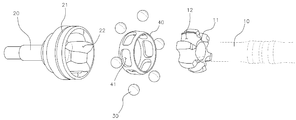
도 2 는 드라이브샤프트가 분해됐을 때의 모습을 도시한 도면,
도 3 은 도 2 의 케이지를 확대하여 도시한 도면,
도 4 는 케이지의 안착홀에 볼이 위치했을 때의 단면 모습들을 도시한 것으로써, 도 1 에서 A-A 부분의 단면상태(종래 구조의 단면상태)<a>, 본 발명의 실시예들에 따라 안착홀 내주면이 볼을 향하는 끝단쪽으로 갈수록 두께가 좁아지는 모양을 갖도록 형성된 상태<b, c>, 안착홀 내주면의 상단 또는 하단의 모서리가 절삭된 상태<d>, 안착홀 내주면이 호형으로 형성된 상태<e>, 안착홀 내주면이 사다리꼴로 형성된 상태<f>, 서로 마주하는 안착홀 내주면의 양측 각각이 다른 모양으로 형성된 상태<g> 를 각각 도시한 도면.1 is a view showing a position where a drive shaft is mounted on a vehicle body,
2 is a view showing a state when the drive shaft is disassembled,
Figure 3 is an enlarged view of the cage of Figure 2,
FIG. 4 is a cross-sectional view of the cage when the ball is placed in the seating hole. FIG. 4 is a cross-sectional view of the AA portion in FIG. 1 (a cross-sectional view of the conventional structure) B "," b "," b "," d ", and " e >, a state <f> in which the inner circumferential surface of the seating hole is formed in a trapezoid, and a state <g> in which the opposite sides of the inner circumferential surface of the seating hole facing each other have different shapes.
이하, 첨부된 도면에 의거하여 본 발명에 대하여 본 발명이 속하는 기술 분야에서 통상의 지식을 가진 자가 용이하게 실시할 수 있도록 상세히 설명한다. 그러나 본 발명은 여러 가지 상이한 형태로 구현될 수 있으며 여기에서 설명하는 실시예에 한정되지 않는다.Hereinafter, embodiments of the present invention will be described in detail with reference to the accompanying drawings in order that the present invention can be easily carried out by those skilled in the art. The present invention may, however, be embodied in many different forms and should not be construed as limited to the embodiments set forth herein.
본 발명을 명확하게 설명하기 위해서 설명과 관계없는 부분은 생략하였으며, 명세서 전체를 통하여 동일 또는 유사한 구성요소에 대해서는 동일한 참조 부호를 붙이도록 한다.In order to clearly illustrate the present invention, parts not related to the description are omitted, and the same or similar components are denoted by the same reference numerals throughout the specification.
또한, 본 명세서 및 특허청구범위에 사용된 용어나 단어는 통상적이거나 사전적인 의미로 한정하여 해석되어서는 안되며, 발명자는 그 자신의 발명을 가장 최선의 방법으로 설명하기 위해 용어의 개념을 적절하게 정의할 수 있다는 원칙에 입각하여 본 발명의 기술적 사상에 부합하는 의미와 개념으로 해석되어야만 한다.In addition, terms and words used in the present specification and claims should not be construed as limited to ordinary or dictionary meanings, and the inventor should properly define the concept of the term to describe its invention in the best way. It should be construed as meaning and concept consistent with the technical idea of the present invention.
본 발명의 드라이브샤프트는 종래 구성과 마찬가지로 제1샤프트(10)와 제2샤프트(20)가 결합되어 구성되되, 상기 제1샤프트(10)와 제2샤프트(20)에 사이에 배치된 케이지(40)는 고분자재료로 제조되는 것을 특징으로 하며, 이하, 본 발명의 바람직한 실시예에 따른 드라이브샤프트의 구조를 더욱 상세하게 설명한다.The drive shaft of the present invention is constructed in such a manner that a
도면들에 도시된 바와 같이, 상기 제1샤프트(10)는 일단은 트랜스미션(또는 디퍼련셜기어박스나 트랜스퍼케이스)이나 휠 중 어느 한쪽으로 연결되고 타단에는 이너레이스(11)가 장착되며, 상기 이너레이스(11)의 외주면에는 둘레를 따라 볼(30)의 갯수와 동일한 갯수의 내측구속홈들(12)이 형성된다.As shown in the drawings, the
상기 제2샤프트(20)는 일단은 트랜스미션(또는 디퍼련셜기어박스나 트랜스퍼케이스)이나 휠 중 다른 한쪽으로 연결되고 타단에는 이너레이스(11)가 내부로 진입가능하도록 컵모양의 아우터레이스(21)가 형성된다. 그리고, 상기 아우터레이스(21)의 내주면에는 둘레를 따라서 볼(30)의 갯수와 동일한 갯수의 외측구속홈들(22) 형성된다.The
상기 볼(30)은 각각의 내측구속홈들(12)과 외측구속홈들(22) 사이에서 구름운동이 가능하게 케이지(40)와 함께 장착된다. 즉, 상기 케이지(40)는 이너레이스(11)와 아우터레이스(21) 사이에 장착될 수 있는 모양과 크기를 갖되 각각의 볼들(30)이 놓이는 다수 개의 안착홀들(41)이 둘레를 따라 형성되고, 이너레이스(11)와 아우터레이스(21) 사이에서 볼(30)의 이탈을 방지하며 이너레이스(11)의 축 방향 및 반경방향의 위치를 규제한다. The
그리고, 본 발명의 케이지(40)는 엔지니어링 플라스틱과 같은 고분자재료(가령, 스틸보다 더 낮은 마찰계수를 갖는 열가소성 엔지니어링 플라스틱)로 제조된다. 특히, 상기 케이지(40)는 금속재인 볼(30)과 접촉시 마찰계수가 0.4 이하가 되는 자기 윤활성(self-lubricative)을 갖는 고분자재료 예를 들어, 열가소성수지(thermoplastic resin)로 제조된다. And, the
가령, 종래의 금속재 케이지의 경우, 금속재인 볼(30)과 접촉할 때 윤활유가 있으면 대략 0.16 정도의 마찰계수를 가지며 윤활유가 없으면 대략 0.5 내지 0.8 정도의 마찰계수를 가지는 반면에, 본 발명과 같이 케이지(40)가 열가소성 엔지니어링 플라스틱으로 제조되는 경우, 윤활유가 없을 때도 대략 0.2 내지 0.4 정도의 마찰계수를 가지며 윤활유가 있을 때는 대략 0.01 내지 0.05 정도의 마찰계수를 가질 수 있다. For example, in the case of a conventional metal cage, when there is lubricating oil in contact with the
또한, 본 발명에서는 볼(30)을 지지할 때 마찰력을 추가적으로 감소시킬 수 있게 볼(30)과 케이지(40)의 접촉면적을 줄일 수 있도록(즉, 종래의 면접촉 구조에서 선접촉 구조로 변경되도록) 상기 안착홀 내주면(41a)의 어느 한쪽은 볼(30)을 향하는 끝단쪽으로 갈수록 두께가 좁아지는 모양으로 형성된다.Further, in the present invention, in order to further reduce the frictional force when the
예를 들어, 도 4 에 도시된 바와 같이 안착홀 내주면(41a)의 볼(30)을 향하는 끝단의 단면 모양은 도 4 의 <b, c> 와 같이 '▶' 와 같이 뾰족한 형태로 형성될 수 있다. 또는, 도 4 의 <e> 와 같이 '⊃' 와 같이 볼록한 호형(弧形)으로 형성될 수도 있다. For example, as shown in FIG. 4, the cross-sectional shape of the end of the
물론, 안착홀 내주면(41a)의 볼(30)을 향하는 끝단의 단면 모양은 선접촉이 가능한 모양에 한정되지 않으며 사다리꼴(도 4 의 <f>), 직사각 또는 다각형(도 4 의 <d>) 단면 모양을 갖게 구성될 수도 있고, 일측과 타측의 단면 모양을 다르게 형성할 수도 있다(도 4 의 <g>). 즉, 안착홀 내주면(41a)의 어느 한쪽의 모양과 볼을 사이에 두고 다른 한쪽의 모양은 서로 다르게 형성될 수도 있다.Of course, the cross-sectional shape of the end of the
상기와 같은 구성을 갖는 본 발명은 사출성형 등과 같은 방식으로 케이지(40)를 제조가능하므로 형상변경이 필요할 때 사출금형의 수정을 통해 용이하고 보다 신속하게 대처할 수 있고, 다양한 형상 및 치수를 갖도록 제작이 가능하다. 그리고, 종래의 금속재 케이지 보다 중량을 저감할 수 있다.Since the
또한, 본 발명에서 고분자재료는 자기윤활성을 갖도록 구성됨에 따라 추가적인 표면처리가 불필요하며 윤활제의 사용을 줄일 수 있고, 마찰력을 최소화하여 소음 및 진동 발생을 억제할 수 있으며, 안착홀 내주면은 볼을 향하는 끝단쪽으로 갈수록 두께가 좁아지는 모양을 갖거나 또는 볼을 향하는 끝단이 호형(弧形)으로 볼록하게 형성되어 종래의 구조에서는 볼이 면접촉하던 구성과는 다르게 볼과 선접촉하게 되므로 접촉면적을 줄여 마찰력을 더욱 감소시킬 수 있다.In addition, since the polymer material of the present invention is configured to have self-lubricating properties, additional surface treatment is unnecessary, use of a lubricant can be reduced, frictional force can be minimized, noise and vibration can be suppressed, The thickness is narrowed toward the end, or the tip toward the ball is formed convexly in an arcuate shape. Thus, unlike the structure in which the ball is in surface contact in the conventional structure, The frictional force can be further reduced.
이상에서 설명한 본 발명은 전술한 실시예 및 첨부된 도면에 의해 한정되는 것이 아니고, 본 발명의 기술적 사상을 벗어나지 않는 범위 내에서 여러 가지 치환, 변형 및 변경이 가능하다는 것이 본 발명이 속하는 기술분야에서 통상의 지식을 가진 자에게 있어 명백할 것이다.It will be apparent to those skilled in the art that various modifications and variations can be made in the present invention without departing from the spirit or scope of the invention. Will be apparent to those of ordinary skill in the art.
10 : 제1샤프트
11 : 이너레이스
12 : 내측구속홈
20 : 제2샤프트
21 : 아우터레이스
22 : 외측구속홈
30 : 볼
40 : 케이지
41 : 안착홀10: First shaft
11: Inner race
12: inner restraining groove
20: Second shaft
21: Outer race
22: outer restraint groove
30: view
40: Cage
41: Seated hole
Claims (7)
상기 이너레이스가 내부로 진입가능하도록 일측 끝단에서 컵모양의 아우터레이스가 형성된 제2샤프트;
상기 이너레이스의 외주면에 형성된 내측구속홈들과 아우터레이스의 내주면에 형성된 외측구속홈들 사이에서 구름운동이 가능하게 장착되는 다수 개의 볼;
각각의 볼들이 놓이는 다수 개의 안착홀들이 둘레를 따라 형성되며, 이너레이스와 아우터레이스 사이에 장착되어 볼의 이탈을 방지하는 케이지;를 포함하고,
상기 케이지는 고분자재료로 제조된 것을 특징으로 하는 드라이브샤프트의 구조.
A first shaft having an inner race at one end;
A second shaft having a cup-like outer race formed at one end thereof so that the inner race can enter into the inner race;
A plurality of balls mounted in a rolling motion between inner confining grooves formed on an outer circumferential surface of the inner race and outer confining grooves formed on an inner circumferential surface of the outer race;
And a cage formed between the inner race and the outer race to prevent the balls from being separated from each other,
Wherein the cage is made of a polymeric material.
The structure of drive shaft according to claim 1, characterized in that either one of the inner circumferential surfaces of the mounting holes has a shape that becomes narrower toward an end toward a ball.
상기 이너레이스가 내부로 진입가능하도록 일측 끝단에서 컵모양의 아우터레이스가 형성된 제2샤프트;
상기 이너레이스의 외주면에 형성된 내측구속홈들과 아우터레이스의 내주면에 형성된 외측구속홈들 사이에서 구름운동이 가능하게 장착되는 다수 개의 볼;
각각의 볼들이 놓이는 다수 개의 안착홀들이 둘레를 따라 형성되며, 이너레이스와 아우터레이스 사이에 장착되어 볼의 이탈을 방지하는 케이지;를 포함하고,
상기 안착홀 내주면의 어느 한쪽은 볼을 향하는 끝단쪽으로 갈수록 두께가 좁아지는 모양을 갖는 것을 특징으로 하는 드라이브샤프트의 구조.
A first shaft having an inner race at one end;
A second shaft having a cup-like outer race formed at one end thereof so that the inner race can enter into the inner race;
A plurality of balls mounted in a rolling motion between inner confining grooves formed on an outer circumferential surface of the inner race and outer confining grooves formed on an inner circumferential surface of the outer race;
And a cage formed between the inner race and the outer race to prevent the balls from being separated from each other,
And one of the inner circumferential surfaces of the seating holes has a shape that becomes narrower toward an end toward the ball.
The drive shaft according to any one of claims 1 to 3, wherein the cage is made of a polymer material having a self-lubricative property with a frictional coefficient of 0.4 or less upon contact with a metal ball. Structure.
The structure of drive shaft according to claim 4, wherein the polymer material having self-lubricating property is a thermoplastic resin.
4. The drive shaft structure according to any one of claims 1 to 3, wherein one of the inner circumferential surfaces of the mounting hole has a shape in which an end portion of the inner circumferential surface facing the ball is convex in an arcuate shape.
Priority Applications (1)
| Application Number | Priority Date | Filing Date | Title |
|---|---|---|---|
| KR1020160072568A KR20170139934A (en) | 2016-06-10 | 2016-06-10 | Structure of drive-shaft |
Applications Claiming Priority (1)
| Application Number | Priority Date | Filing Date | Title |
|---|---|---|---|
| KR1020160072568A KR20170139934A (en) | 2016-06-10 | 2016-06-10 | Structure of drive-shaft |
Publications (1)
| Publication Number | Publication Date |
|---|---|
| KR20170139934A true KR20170139934A (en) | 2017-12-20 |
Family
ID=60931614
Family Applications (1)
| Application Number | Title | Priority Date | Filing Date |
|---|---|---|---|
| KR1020160072568A KR20170139934A (en) | 2016-06-10 | 2016-06-10 | Structure of drive-shaft |
Country Status (1)
| Country | Link |
|---|---|
| KR (1) | KR20170139934A (en) |
Cited By (2)
| Publication number | Priority date | Publication date | Assignee | Title |
|---|---|---|---|---|
| CN111623047A (en) * | 2020-06-08 | 2020-09-04 | 杭州杭海实业有限公司 | Ball cage retainer of automobile driving shaft assembly and preparation process thereof |
| CN111678495A (en) * | 2020-06-08 | 2020-09-18 | 杭州杭海实业有限公司 | Precision automatic quick detection system and detection method of ball cage retainer |
-
2016
- 2016-06-10 KR KR1020160072568A patent/KR20170139934A/en not_active Application Discontinuation
Cited By (4)
| Publication number | Priority date | Publication date | Assignee | Title |
|---|---|---|---|---|
| CN111623047A (en) * | 2020-06-08 | 2020-09-04 | 杭州杭海实业有限公司 | Ball cage retainer of automobile driving shaft assembly and preparation process thereof |
| CN111678495A (en) * | 2020-06-08 | 2020-09-18 | 杭州杭海实业有限公司 | Precision automatic quick detection system and detection method of ball cage retainer |
| CN111623047B (en) * | 2020-06-08 | 2021-07-30 | 杭州杭海实业有限公司 | Ball cage retainer of automobile driving shaft assembly and preparation process thereof |
| CN111678495B (en) * | 2020-06-08 | 2022-05-17 | 杭州杭海实业有限公司 | Ball cage retainer, automatic precision quick detection system of ball cage retainer and detection method of ball cage retainer |
Similar Documents
| Publication | Publication Date | Title |
|---|---|---|
| US8944693B2 (en) | Rolling bearing cage and rolling bearing | |
| US7775722B2 (en) | Double-row antifriction bearing | |
| JP6922928B2 (en) | Cage for rolling bearings and rolling bearings | |
| CN100400907C (en) | Rotation support device for compressor pulley | |
| US20070116395A1 (en) | Ball bearing | |
| EP2811188B1 (en) | Ball bearing | |
| US20090290826A1 (en) | Rolling element bearing with different guide pockets | |
| US20130337953A1 (en) | Pulley device for an air conditioning compressor | |
| US20160290398A1 (en) | Rolling bearing | |
| KR20170139934A (en) | Structure of drive-shaft | |
| JP2007292093A (en) | Deep groove ball bearing | |
| JP2000291662A (en) | Ball bearing | |
| JP2012255479A5 (en) | ||
| JP2011149551A (en) | Tripod constant-velocity universal joint | |
| JP4554306B2 (en) | Constant velocity joint | |
| JP2012189190A (en) | Sliding-type constant-velocity universal joint | |
| JP2021143716A (en) | Rotation transmission slide spline shaft and constant velocity universal joint | |
| JP2009115224A (en) | Crown-shaped cage for ball bearing and deep groove ball bearing | |
| JP6790517B2 (en) | Tapered roller bearing | |
| US9447824B2 (en) | Universal joint | |
| JP2013117238A (en) | Ball bearing retainer, and ball bearing | |
| JP7250577B2 (en) | Separate inner ring type angular contact ball bearing | |
| CN113195915B (en) | Tripod constant velocity universal joint | |
| JP6904891B2 (en) | Vehicle constant velocity universal joint | |
| JP2006097758A (en) | Constant velocity joint |
Legal Events
| Date | Code | Title | Description |
|---|---|---|---|
| E902 | Notification of reason for refusal | ||
| E601 | Decision to refuse application |