KR20170134174A - A vessel having a retractable cursor frame assembly - Google Patents
A vessel having a retractable cursor frame assembly Download PDFInfo
- Publication number
- KR20170134174A KR20170134174A KR1020167030908A KR20167030908A KR20170134174A KR 20170134174 A KR20170134174 A KR 20170134174A KR 1020167030908 A KR1020167030908 A KR 1020167030908A KR 20167030908 A KR20167030908 A KR 20167030908A KR 20170134174 A KR20170134174 A KR 20170134174A
- Authority
- KR
- South Korea
- Prior art keywords
- guide rail
- shaped guide
- track
- vessel
- crossbar
- Prior art date
Links
Images


Classifications
-
- B—PERFORMING OPERATIONS; TRANSPORTING
- B63—SHIPS OR OTHER WATERBORNE VESSELS; RELATED EQUIPMENT
- B63B—SHIPS OR OTHER WATERBORNE VESSELS; EQUIPMENT FOR SHIPPING
- B63B27/00—Arrangement of ship-based loading or unloading equipment for cargo or passengers
- B63B27/08—Arrangement of ship-based loading or unloading equipment for cargo or passengers of winches
-
- B—PERFORMING OPERATIONS; TRANSPORTING
- B63—SHIPS OR OTHER WATERBORNE VESSELS; RELATED EQUIPMENT
- B63B—SHIPS OR OTHER WATERBORNE VESSELS; EQUIPMENT FOR SHIPPING
- B63B27/00—Arrangement of ship-based loading or unloading equipment for cargo or passengers
- B63B27/14—Arrangement of ship-based loading or unloading equipment for cargo or passengers of ramps, gangways or outboard ladders ; Pilot lifts
- B63B27/146—Pilot ladders or similar outboard ladders, e.g. bathing ladders; Pilot lifts
-
- B—PERFORMING OPERATIONS; TRANSPORTING
- B63—SHIPS OR OTHER WATERBORNE VESSELS; RELATED EQUIPMENT
- B63B—SHIPS OR OTHER WATERBORNE VESSELS; EQUIPMENT FOR SHIPPING
- B63B27/00—Arrangement of ship-based loading or unloading equipment for cargo or passengers
- B63B27/16—Arrangement of ship-based loading or unloading equipment for cargo or passengers of lifts or hoists
-
- B—PERFORMING OPERATIONS; TRANSPORTING
- B63—SHIPS OR OTHER WATERBORNE VESSELS; RELATED EQUIPMENT
- B63B—SHIPS OR OTHER WATERBORNE VESSELS; EQUIPMENT FOR SHIPPING
- B63B27/00—Arrangement of ship-based loading or unloading equipment for cargo or passengers
- B63B27/14—Arrangement of ship-based loading or unloading equipment for cargo or passengers of ramps, gangways or outboard ladders ; Pilot lifts
- B63B27/146—Pilot ladders or similar outboard ladders, e.g. bathing ladders; Pilot lifts
- B63B2027/148—Pilot lifts
-
- B—PERFORMING OPERATIONS; TRANSPORTING
- B63—SHIPS OR OTHER WATERBORNE VESSELS; RELATED EQUIPMENT
- B63B—SHIPS OR OTHER WATERBORNE VESSELS; EQUIPMENT FOR SHIPPING
- B63B27/00—Arrangement of ship-based loading or unloading equipment for cargo or passengers
- B63B27/16—Arrangement of ship-based loading or unloading equipment for cargo or passengers of lifts or hoists
- B63B2027/165—Deployment or recovery of underwater vehicles using lifts or hoists
-
- B63B2708/00—
-
- B—PERFORMING OPERATIONS; TRANSPORTING
- B63—SHIPS OR OTHER WATERBORNE VESSELS; RELATED EQUIPMENT
- B63G—OFFENSIVE OR DEFENSIVE ARRANGEMENTS ON VESSELS; MINE-LAYING; MINE-SWEEPING; SUBMARINES; AIRCRAFT CARRIERS
- B63G8/00—Underwater vessels, e.g. submarines; Equipment specially adapted therefor
- B63G8/001—Underwater vessels adapted for special purposes, e.g. unmanned underwater vessels; Equipment specially adapted therefor, e.g. docking stations
- B63G2008/002—Underwater vessels adapted for special purposes, e.g. unmanned underwater vessels; Equipment specially adapted therefor, e.g. docking stations unmanned
Landscapes
- Chemical & Material Sciences (AREA)
- Engineering & Computer Science (AREA)
- Combustion & Propulsion (AREA)
- Mechanical Engineering (AREA)
- Ocean & Marine Engineering (AREA)
- Earth Drilling (AREA)
- Vehicle Step Arrangements And Article Storage (AREA)
- Support Devices For Sliding Doors (AREA)
- Connection Of Plates (AREA)
- Jib Cranes (AREA)
Abstract
본 발명은, 다른 베셀들을 바다로 배치하기 위한 연장가능하고 수축가능한 커서 프레임 조립체를 갖는 선박에 관한 것이다. 주 선박 상의 수축가능한 커서 프레임 조립체는, 주 선박이 이동 중일 때 주 선박의 모듈 상에서 수축되고 고정될 수 있다. 다른 베셀이 주 선박으로부터 바다로 배치되는 경우, 커서 프레임 조립체가 바다로 연장되어 다른 베셀의 진수를 용이하게 한다.The present invention relates to a vessel having an extensible and retractable cursor frame assembly for placing other vessels into the sea. The retractable cursor frame assembly on the main vessel may be retracted and secured on the module of the primary vessel when the primary vessel is moving. When another vessel is placed into the sea from the main vessel, the cursor frame assembly extends into the sea to facilitate launching of the other vessel.
Description
본 발명은, 다른 베셀(vessel)들을 바다(a body of water)로 배치하기 위한 연장가능하고 수축가능한 커서(cursor) 프레임 조립체를 갖는 선박에 관한 것이다. 더 상세하게는, 본 발명은, 주 선박이 이동 중일 때 주 선박의 모듈 상에서 수축되고 고정되는, 주 선박 상의 수축가능한 커서 프레임 조립체에 관한 것이다. 다른 베셀이 주 선박으로부터 인접한 바다로 배치되는 경우, 커서 프레임 조립체가 바다로 연장되어 다른 베셀의 진수(launch)를 용이하게 한다.The present invention relates to a vessel having an extendable and retractable cursor frame assembly for placing other vessels in the body of water. More particularly, the present invention relates to a shrinkable cursor frame assembly on a main vessel, wherein the main vessel is contracted and secured on the module of the main vessel when the main vessel is moving. When another vessel is positioned from the main vessel to the adjacent sea, the cursor frame assembly extends into the sea to facilitate launching of the other vessels.
심해 또는 연안 위치들에서와 같이 준-위험 조건들 하에서 탐험하는 경우, 특정 사이트(site) 또는 위치에 대한 접근하기 위해 원격무인장비(Remotely Operated Vehicles, ROV)들이 통상적으로 활용된다. ROV들은, 먼바다에서 선박들의 항해를 위해 그리고 다양한 상이한 수중 작업들의 완료를 위해 이용될 수 있다. 이러한 ROV들은 통상적으로 자체 추진되고, 통상적으로 다양한 연결장치들을 포함하여, 장비의 회수와 같은 활동들이 달성되게 한다. ROV들에는 또한 통상적으로 비디오 기록 장비 및 조명이 제공되어, ROV의 제어기가 ROV를 더 양호하게 조작하게 하여, ROV가 자신의 수중 작업들을 달성할 수 있게 한다. Remotely Operated Vehicles (ROVs) are routinely used to access specific sites or locations when exploring under sub-hazardous conditions, such as at deep sea or coastal locations. ROVs can be used for navigating ships in distant lands and for completing a variety of different underwater tasks. These ROVs are typically self-propelled, typically including a variety of connection devices, such that activities such as the return of equipment are achieved. The ROVs are also typically provided with video recording equipment and lighting, allowing the ROV's controller to better manipulate the ROV so that the ROV can achieve its own underwater tasks.
먼바다에서, ROV들은 종종 테더(tether) 및 윈치(winch) 시스템들을 이용하여 배치된다. 테더 및 윈치 시스템은, 내부에 ROV를 운반할 수 있는 케이지(cage) 또는 캐리지(carriage), 또는 ROV가 아래에 저장되는 톱 햇(top hat) 타입의 캐리지를 포함할 수 있다. 그 다음, ROV를 운반하는 캐리지는, 윈치 시스템을 이용하여 주 선박으로부터 바다로 하강된다. 캐리지가 해수면에 도달하는 경우, ROV는 캐리지로부터 분리되고, 그 다음, 제어기에 의해 작업 사이트로 향한다. 수중에서 ROV의 동작을 용이하게 하기 위해, ROV는 통상적으로 긴 케이블을 통해 주 선박에 묶인다. 이러한 케이블을 통해, ROV는, 주 선박으로부터 ROV로 전송되는 전력 및 신호들을 수신할 것이다.In the distance, ROVs are often deployed using tether and winch systems. The tether and winch system may include a cage or carriage that can carry the ROV inside, or a top hat type carriage in which the ROV is stored below. The carriage carrying the ROV is then lowered from the main vessel to the sea using a winch system. When the carriage reaches the sea level, the ROV is detached from the carriage and then directed to the job site by the controller. In order to facilitate the operation of the ROV in water, the ROV is typically tied to the main vessel via a long cable. Through this cable, the ROV will receive the power and signals transmitted from the main vessel to the ROV.
이러한 배치(deployment) 시스템은 오직 양호한 날씨 조건들에서만 활용될 수 있다. 폭풍우가 있는 바다, 강한 바람 및 거친 파도가 존재하는 열악한 날씨 조건들에서는, 캐리지가 바다로 윈치될 때, ROV를 운반하는 캐리지가 출렁거리게(tossed and spun around) 될 것이어서, 이러한 배치 시스템은 이용될 수 없다. 이러한 조건들 하에서는, ROV를 바다로 배치하기 위해 커서 프레임 조립체가 통상적으로 활용된다. 대부분의 선박들의 경우, 커서 프레임은, 선박의 주 갑판으로부터 용골선(keel line)까지 선박의 선체(hull) 측면에 부착될 것이다. ROV가 배치되는 경우, ROV는 커서 프레임에 연결된 캐리지에 배치될 것이다. 그 다음, 윈치 또는 크레인이 이용되어, 캐리지 및 그에 포함된 ROV를 바다로 하강시킬 것이다. 캐리지는 오직 커서 프레임의 방향을 따라서만 이동할 수 있기 때문에, 캐리지의 제한된 수직 이동으로 인해 가장 거친 바다 조건 하에서도, 캐리지는 ROV를 안전하게 바다에 배치할 수 있다. 커서 프레임이 이용되지 않는 경우 또는 선박이 이동 중인 경우, 커서 프레임은 선박의 선체로부터 제거되어야 한다. 이것은, 커서 프레임이 선체에 부착되어 남아있으면, 선박의 이동 속력이 심각하게 감소되기 때문이다. 예를 들어, 선박의 통상적인 이동 속력은 12 내지 14 노트이다. 커서 프레임이 선체에 부착되어 있으면, 선박은 통상적으로 3.5 노트의 이동 속력으로 제한될 것이다. 선박의 이동 속력을 증가시키면, 커서 프레임이 선박의 선체로부터 이탈되는 것을 초래할 것이다. 커서 프레임을 제거하기 위해, 선박의 선체 상에 제공되는 리그(rig) 크레인들이 통상적으로 배치되어, 커서 프레임을 들어올려 커서 프레임을 선박의 갑판 상에 배치한다. 이에 따른 문제점은, 커서 프레임이 매우 길고 부피가 커서, 프레임은 선박 상의 중요한 갑판 공간의 상당한 영역을 차지할 것이라는 점이다. This deployment system can only be utilized in good weather conditions. In harsh weather conditions where stormy seas, strong winds and rough waves are present, as the carriage is winch into the sea, the carriage carrying the ROV will be tossed and spun around, I can not. Under these conditions, a cursor frame assembly is commonly utilized to place ROVs into the ocean. For most ships, the cursor frame will be attached to the hull side of the ship from the ship's main deck to the keel line. If the ROV is deployed, the ROV will be placed in the carriage connected to the cursor frame. A winch or crane is then used to lower the carriage and the ROV contained therein to the sea. Because the carriage can only move along the direction of the cursor frame, due to the limited vertical movement of the carriage, the carriage can safely place the ROV in the sea even under the harshest sea conditions. If the cursor frame is not used or the ship is moving, the cursor frame shall be removed from the ship's hull. This is because if the cursor frame remains attached to the hull, the speed of movement of the ship is seriously reduced. For example, the typical speed of a ship is 12 to 14 knots. If the cursor frame is attached to the hull, the vessel will normally be limited to a traveling speed of 3.5 knots. Increasing the speed of movement of the ship will cause the cursor frame to deviate from the hull of the ship. To remove the cursor frame, rig cranes provided on the ship's hull are typically positioned to lift the cursor frame and place the cursor frame on the ship's deck. A problem with this is that the cursor frame is very long and bulky, so that the frame will occupy a significant area of the important deck space on the ship.
갑판 공간의 부족은 해안 드릴링 리그들에 의해 통상적으로 직면되는 문제인데, 이는, 이러한 시스템들에 이용가능하게 되는 갑판 공간의 양이 통상적으로 제한되기 때문이다. 또한, 주 ROV에 추가로, 대부분의 선박들은 선박에 대체 ROV를 탑재하는 경향이 있을 것이다. 이것은, 주 ROV가 기술적 문제들에 직면하는 경우, 대체 ROV가 그 대신 활용될 수 있게 하기 위함이다. 추가적인 ROV를 탑재하는 것의 단점은, 대체 유닛이 또한 주 선박 상에서 추가적인 갑판 공간을 차지할 것이라는 점이다.The lack of deck space is a problem typically encountered by coastal drilling rigs because the amount of deck space available to such systems is typically limited. Also, in addition to the main ROV, most vessels will tend to load alternative ROVs on their vessels. This is so that if the primary ROV is faced with technical problems, an alternative ROV can be utilized instead. A disadvantage of having additional ROVs is that alternate units will also occupy additional deck space on the main vessel.
기존의 ROV 배치 시스템들은, 이러한 시스템들이 비효율적이고, 부피가 크고, 열악한 날씨에서 이용하기에 위험하고 그리고/또는 선박의 선체로부터 분리되는 경우 중요한 갑판 공간을 점유하기 때문에 불리하다. 따라서, 당업자들은, 선박이 이동 중인 경우 선박으로부터 분리될 필요가 없고, 모든 날씨 조건들에서 이용하기에 본질적으로 안전하며, 기존의 배치 시스템들에 의해 직면되는 문제점들을 처리하는 선박용 커서 프레임을 고안하기 위한 방법들을 지속적으로 찾고 있다.Conventional ROV placement systems are disadvantageous because such systems are inefficient, bulky, dangerous to use in harsh weather and / or occupy important deck space when separated from the ship's hull. Those skilled in the art will therefore appreciate that there is a need in the art to devise a vessel cursor frame that does not need to be separated from the vessel when the vessel is moving and is inherently safe for use in all weather conditions and addresses the problems faced by existing batch systems We are constantly looking for ways to.
본 발명에 따르면, 본 기술분야의 상기 문제점들 및 다른 문제점들이 해결되며 본 기술분야에서의 진보가 달성된다. 본 발명에 따른 연장가능하고 수축가능한 커서 프레임 조립체를 갖는 선박의 제 1 이점은, 선박이 이동 중인 경우 커서 프레임이 선박으로부터 분리될 필요가 없다는 점이다. 이것은, 선박의 갑판 상의 중요한 공간을 비워 둔다. 본 발명에 따른 커서 프레임 조립체의 제 2 이점은, 나쁜 날씨 조건들에서도 ROV들을 배치하기 위해 커서 프레임이 이용될 수 있다는 점이다. 본 발명에 따른 커서 프레임 조립체의 제 3 이점은, C-형상 안내 레일들이 슬라이딩가능하게 T-형상 트랙들과 맞물리는 방식으로 인해, 프레임 조립체의 안내 레일들이 이들 각각의 트랙들과 단단한 그리고 견고한 방식으로 맞물린다는 점이다.In accordance with the present invention, the above and other problems in the art are addressed and progress in the art is achieved. A first advantage of a vessel with an extendible and retractable cursor frame assembly according to the present invention is that the cursor frame need not be separated from the vessel when the vessel is moving. This leaves the crucial space on the deck of the ship empty. A second advantage of the cursor frame assembly in accordance with the present invention is that a cursor frame can be used to place ROVs even in bad weather conditions. A third advantage of the cursor frame assembly in accordance with the present invention is that the manner in which the C-shaped guide rails engage the T-shaped tracks slidably engages the guide rails of the frame assembly with their respective tracks in a rigid and rigid manner .
본 발명의 실시예들에 따르면, 연장가능하고 수축가능한 커서 프레임 조립체를 갖는 선박은 제 1 트랙 및 제 2 트랙을 포함하고, 각각의 트랙은 베이스(base) 부분 및 베이스 부분으로부터 돌출되는 블레이드(blade) 부분을 갖는다. 각각의 트랙의 경우, 트랙의 상측 절반은 트랙의 블레이드 부분을 통해 선박의 선체 상측에 제공되는 모듈에 부착되고, 트랙의 하측 절반은 트랙의 블레이드 부분을 통해 선박의 선체에 부착된다. 커서 프레임 조립체는 또한, 제 1 트랙과 슬라이딩가능하게 맞물리는 제 1 C-형상 안내 레일 및 제 2 트랙과 슬라이딩가능하게 맞물리는 제 2 C-형상 안내 레일을 포함한다. 제 1 C-형상 안내 레일은 제 1 트랙의 길이보다 짧은 길이를 갖고, 제 2 C-형상 안내 레일은 제 2 트랙의 길이보다 짧은 길이를 갖는다. 추가로, 조립체는 또한, 제 1 C-형상 안내 레일을 고정시키기 위해 제 1 트랙의 제 1 단부에 인접한 모듈 상에 제공되는 제 1 고정 구조물 및 제 2 C-형상 안내 레일을 고정시키기 위해 제 2 트랙의 제 1 단부에 인접한 모듈 상에 제공되는 제 2 고정 구조물을 포함한다. 제 1 C-형상 안내 레일을 완충(buffering)시키기 위해 제 1 트랙의 제 2 단부에 제공되는 제 1 브레이스(brace) 및 제 2 C-형상 안내 레일을 지지(supporting)하기 위해 제 2 트랙의 제 2 단부에 제공되는 제 2 브레이스가 또한 커서 프레임 조립체에 포함된다. 본 발명의 실시예들에 따르면, 제 1 및 제 2 C-형상 안내 레일들의 길이는 선박의 선체 상측의 모듈의 높이와 동일하다. According to embodiments of the present invention, a vessel having an extensible and retractable cursor frame assembly includes a first track and a second track, each track having a base portion and a blade ) Portion. For each track, the upper half of the track is attached to the module provided on the ship's hull over the blade portion of the track, and the lower half of the track is attached to the hull of the ship through the blade portion of the track. The cursor frame assembly also includes a first C-shaped guide rail slidably engaged with the first track and a second C-shaped guide rail slidably engaged with the second track. The first C-shaped guide rail has a length less than the length of the first track and the second C-shaped guide rail has a length less than the length of the second track. Additionally, the assembly may also include a first fastening structure provided on the module adjacent the first end of the first track for securing the first C-shaped guide rail and a second fastening structure provided on the module adjacent the first end of the first track for securing the second C- And a second securing structure provided on the module adjacent the first end of the track. Shaped guide rails to support a first brace and a second C-shaped guide rail provided on the second end of the first track for buffering the first C-shaped guide rails, A second brace provided at the two ends is also included in the cursor frame assembly. According to embodiments of the present invention, the length of the first and second C-shaped guide rails is the same as the height of the module above the hull of the ship.
본 발명의 실시예들에 따르면, 제 1 고정 구조물은, 제 1 트랙의 제 1 단부의 제 1 측면에 제공되는 제 1 브래킷(bracket) 및 제 1 트랙의 제 1 단부의 제 2 측면에 제공되는 제 2 브래킷을 포함한다. 상기 고정 구조물은 또한, 제 1 C-형상 안내 레일을 모듈에 고정시키기 위해, 제 1 C-형상 안내 레일의 제 1 단부에 제공되는 개구부 및 제 1 및 제 2 브래킷들을 통과하는 고정 부재를 포함한다.According to embodiments of the present invention, the first fixing structure is provided with a first bracket provided on the first side of the first end of the first track and a second bracket provided on the second side of the first end of the first track And a second bracket. The fastening structure also includes an opening provided in the first end of the first C-shaped guide rail and a fastening member passing through the first and second brackets to fasten the first C-shaped guide rail to the module .
본 발명의 실시예들에 따르면, 제 2 고정 구조물은, 제 2 트랙의 제 1 단부의 제 1 측면에 제공되는 제 3 브래킷 및 제 2 트랙의 제 1 단부의 제 2 측면에 제공되는 제 4 브래킷을 포함한다. 상기 고정 구조물은 또한, 제 2 C-형상 안내 레일을 모듈에 고정시키기 위해 제 2 C-형상 안내 레일의 제 1 단부에 제공되는 개구부 및 제 3 및 제 4 브래킷들을 통과하는 고정 부재를 포함한다.According to embodiments of the present invention, the second fixing structure includes a third bracket provided on a first side of the first end of the second track, and a third bracket provided on a second side of the first end of the second track, . The fastening structure also includes an opening provided in the first end of the second C-shaped guide rail for securing the second C-shaped guide rail to the module and a fastening member passing through the third and fourth brackets.
본 발명의 실시예들에 따르면, 선박은, 제 1 및 제 2 C-형상 안내 레일들을 상승 또는 하강시키기 위해 모듈의 상부 표면 상에 제공되는 윈치를 더 포함한다. 본 발명의 실시예들에서, 윈치는 일정 장력 타입(constant tension type) 윈치일 수 있다.According to embodiments of the present invention, the vessel further comprises a winch provided on an upper surface of the module for raising or lowering the first and second C-shaped guide rails. In embodiments of the present invention, the winch may be a constant tension type winch.
본 발명의 실시예들에 따르면, 프레임 조립체는, 제 1 C-형상 안내 레일을 제 2 C-형상 안내 레일에 연결시키는 제 1 가로대(crosspiece)를 포함하고, 제 1 가로대는 제 1 및 제 2 C-형상 안내 레일들에 수직이 되도록 제공된다. 본 발명의 추가적인 실시예들에 따르면, 프레임 조립체는, 제 1 C-형상 안내 레일을 제 2 C-형상 안내 레일에 연결시키는 제 2 가로대를 포함하고, 제 2 가로대는 제 1 가로대와 평행이 되도록 제공된다. 본 발명의 또한 추가적인 실시예들에 따르면, 프레임 조립체는, 제 1 C-형상 안내 레일을 제 2 C-형상 안내 레일에 연결시키는 제 3 가로대를 포함하여, 제 3 가로대의 제 1 단부는, 제 1 C-형상 안내 레일에 연결되는 제 1 가로대의 단부에 연결되고, 제 3 가로대의 제 2 단부는, 제 2 C-형상 안내 레일에 연결되는 제 2 가로대의 단부에 연결된다.According to embodiments of the present invention, the frame assembly includes a first crosspiece connecting the first C-shaped guide rail to the second C-shaped guide rail, and the first crossbar includes first and second And is provided to be perpendicular to the C-shaped guide rails. According to further embodiments of the present invention, the frame assembly includes a second crossbar connecting the first C-shaped guide rail to the second C-shaped guide rail, and the second crossbar is parallel to the first crossbar / RTI > According to still further embodiments of the present invention, the frame assembly includes a third crossbar connecting the first C-shaped guide rail to the second C-shaped guide rail, wherein the first end of the third crossbar Shaped guide rail, and the second end of the third crossbar is connected to the end of the second crossbar connected to the second C-shaped guide rail.
본 발명의 실시예들에 따르면, 프레임 조립체는 원격무인장비를 수용하기 위한 캐리지, 캐리지의 제 1 프레임을 제 1 C-형상 안내 레일에 연결시키기 위한 제 1 캐리지 안내부 및 캐리지의 제 2 프레임을 제 2 C-형상 안내 레일에 연결시키기 위한 제 2 캐리지 안내부를 포함한다.According to embodiments of the present invention, the frame assembly includes a carriage for receiving remote unattended equipment, a first carriage guide for connecting the first frame of the carriage to the first C-shaped guide rail, And a second carriage guide for connecting to the second C-shaped guide rail.
본 발명에 따른 방법 및 장치의 상기 이점들 및 특징들은 하기 상세한 설명에서 설명되고 도면들에 도시된다.
도 1은, 커서 프레임의 안내 레일들이 수축 위치에 있는 본 발명의 실시예에 따른 커서 프레임을 갖는 선박의 측면도를 나타낸다.
도 2는, 커서 프레임의 안내 레일들이 수축 위치에 있는 본 발명의 실시예에 따른 커서 프레임을 갖는 선박의 사시도를 나타낸다.
도 3은, 커서 프레임의 안내 레일들이 배치 위치에 있는 본 발명의 실시예에 따른 커서 프레임을 갖는 선박의 측면도를 나타낸다.
도 4는, 커서 프레임의 안내 레일들이 배치 위치에 있는 본 발명의 실시예에 따른 커서 프레임을 갖는 선박의 사시도를 나타낸다.
도 5a는, 본 발명의 실시예에 따른 수축 위치의 커서 프레임 조립체를 나타낸다.
도 5b는, 본 발명의 실시예에 따라, ROV를 포함한 캐리지가 커서 프레임 조립체 상으로 이동되기 전에 연장 위치에 있는 커서 프레임 조립체를 나타낸다.
도 6은, 본 발명의 실시예에 따라, ROV가 캐리지로부터 배치된 후에 연장 위치에 있는 커서 프레임 조립체를 나타낸다.
도 7은, 본 발명의 실시예에 따라 트랙과 맞물린 안내 레일의 단면도를 나타낸다.
도 8은, 본 발명의 실시예에 따른 고정 구조물들을 나타낸다.
도 9는, 본 발명의 실시예에 따른 고정 구조물의 측면도를 나타낸다.
도 10은, 본 발명의 실시예에 따른 캐리지의 측면도를 나타낸다.
도 11은, 본 발명의 실시예에 따른 캐리지의 정면도를 나타낸다. The advantages and features of the method and apparatus according to the invention are described in the following detailed description and illustrated in the drawings.
Figure 1 shows a side view of a vessel with a cursor frame according to an embodiment of the invention in which the guide rails of the cursor frame are in the retracted position.
Figure 2 shows a perspective view of a vessel with a cursor frame according to an embodiment of the present invention in which the guide rails of the cursor frame are in the retracted position.
Figure 3 shows a side view of a vessel with a cursor frame according to an embodiment of the present invention in which the guide rails of the cursor frame are in an arranged position.
Figure 4 shows a perspective view of a vessel with a cursor frame according to an embodiment of the present invention in which the guide rails of the cursor frame are in an arranged position.
Figure 5a shows a cursor frame assembly in a retracted position according to an embodiment of the present invention.
Figure 5b shows a cursor frame assembly in an extended position before the carriage, including the ROV, is moved onto the cursor frame assembly, in accordance with an embodiment of the present invention.
Figure 6 illustrates a cursor frame assembly in an extended position after the ROV is disposed from the carriage, in accordance with an embodiment of the present invention.
7 shows a cross-sectional view of a guide rail engaged with a track according to an embodiment of the present invention.
Figure 8 shows fastening structures according to embodiments of the present invention.
9 shows a side view of a fixing structure according to an embodiment of the present invention.
10 shows a side view of a carriage according to an embodiment of the present invention.
11 shows a front view of a carriage according to an embodiment of the present invention.
본 발명은, 다른 베셀들을 바다로 배치하기 위한 연장가능하고 수축가능한 커서 프레임 조립체를 갖는 선박에 관한 것이다. 더 상세하게는, 본 발명은, 주 선박이 이동 중일 때 주 선박의 모듈 상에서 수축되고 고정되는, 주 선박 상의 수축가능한 커서 프레임 조립체에 관한 것이다. 다른 베셀이 주 선박으로부터의 인접한 바다로 배치되는 경우, 커서 프레임 조립체가 바다로 연장되어 다른 베셀의 진수를 용이하게 한다.The present invention relates to a vessel having an extensible and retractable cursor frame assembly for placing other vessels into the sea. More particularly, the present invention relates to a shrinkable cursor frame assembly on a main vessel, wherein the main vessel is contracted and secured on the module of the main vessel when the main vessel is moving. When the other vessel is placed into an adjacent sea from the main vessel, the cursor frame assembly extends into the sea to facilitate launching of the other vessel.
도 1은, 본 발명의 실시예에 따른 연장가능하고 수축가능한 커서 프레임 조립체를 갖는 선박을 예시한다. 선박(100)은, 선체(110), 및 선체(110)의 상부면 상에 또는 선박(100)의 갑판 상에 제공되는 모듈(105)을 포함한다. 당업자는, 모듈(105)이, 본 발명으로부터 벗어남이 없이, 머드(mud) 모듈, 저장 모듈 또는 수용 모듈과 같이(그러나 이에 제한되는 것은 아님) 선박(100)의 갑판 상에 설치될 수 있는 임의의 타입의 모듈일 수 있음을 인식할 것이다. 본 발명의 실시예에 따르면, 선박(100)은 드릴쉽을 포함할 수 있는 한편, 모듈(105)은 머드 모듈을 포함할 수 있다. 드릴쉽 상의 머드 모듈은, 머드, 드릴 워터, 연료, 오일, 중정석(Barite) 및 벤토나이트(bentonite)와 같은 드릴링 소모품들, 및/또는 머드 탱크들, 머드 펌프들, 혼합 또는 충전(charging) 펌프들과 같은 머드 시스템들을 하우징하기 위해 이용된다. 종래의 드릴쉽들에서, 드릴링 소모품들 및/또는 머드 시스템들은 통상적으로 드릴쉽의 선체 내에 하우징된다. 이를 행하는 단점은, 드릴링 소모품들이 소진되면, 드릴쉽 내의 부하가 변하기 때문에 드릴쉽의 드래프트(draft)가 변경될 것이라는 점이다.1 illustrates a vessel having an extensible and retractable cursor frame assembly in accordance with an embodiment of the present invention. The
본 발명의 이러한 실시예에서, 드릴링 소모품들 및/또는 머드 시스템들 모두는 머드 모듈 내에 하우징되기 때문에, 이것은, 추가적인 평형수(ballast water)를 운반하기 위해 드릴쉽의 선체 내의 탱크 공간을 비워둔다. 드릴쉽의 선체의 탱크들 내에 제공되는 추가적인 평형수는, 드릴링 소모품들 모두가 소진된 후에도, 드릴쉽의 드래프트를 일정한 레벨로 유지하는 것을 돕는다. 이러한 증가된 안정성은, 드릴쉽이 더 긴 기간 동안 바다에 체류할 수 있음을 의미한다.In this embodiment of the invention, because both drilling consumables and / or mud systems are housed within the mud module, this leaves the tank space in the drill ship's hull to carry additional ballast water. The additional ballast water provided in the tanks of the hull of the drill ship assists in maintaining the draft of the drill ship at a constant level even after all of the drilling consumables have been exhausted. This increased stability means that the drill ship can stay in the ocean for a longer period of time.
도 1에 예시된 바와 같이, 모듈(105)에는, 선박(100)의 갑판에 인접하게 제공되는 개구부(120)가 제공된다. 개구부(120)는 모듈(105)로부터의 및 모듈(105)에의 접근하기 위해 이용될 수 있다. 본 발명의 실시예들에서, 개구부(120)는, ROV를 포함하는 캐리지가 통과할 만큼 충분히 클 수 있다. 도 1은 또한, 모듈(105)에 부착된 상부 섹션 및 선체(110)에 부착된 하부 섹션을 갖는 커서 프레임 조립체(115)를 예시한다. As illustrated in Figure 1, the
선박(100)이 이동 중인 경우, 커서 프레임 조립체(115)는 도 1 및 도 2에 예시된 바와 같이 수축 위치에 있을 것이다. 이러한 수축 위치에서, 커서 프레임 조립체(115)의 안내 레일들은 물 밖으로 수축될 것이고, 고정 구조물들 또는 디바이스들을 이용하여 모듈(105)에 고정될 것이다. ROV가 선박(100)으로부터 배치되는 경우, 커서 프레임 조립체는 도 3 및 도 4에 예시된 바와 같이 배치 위치(deployed position)에 있을 것이다. 이러한 연장 위치(extended position)에서, 커서 프레임 조립체(115)의 안내 레일들은, 선박(100)의 용골 레벨을 지나 인접 바다로 연장될 것이다. 이것은, ROV를 포함하는 캐리지를 모듈(105)의 개구부(120)로부터 바다와 같은 인접 바다로 배치하는 것을 용이하게 한다. 이러한 수축가능하고 연장가능한 커서 프레임 조립체를 갖는 이점은, 선박(100)이 이동 중인 경우, 프레임 조립체(115)가 수면 위로 수축될 수 있고, 모듈(105)의 측면에 단단하게 고정되어, 선박(100)이 더 빠른 이동 속력을 달성하도록 허용할 수 있다는 점이다. 프레임 조립체(115)의 안내 레일들이 바다로 연장되어 유지되면, 선박(100)의 이동 속력은 심각하게 제한될 것이다. 이것은, 선박(100)이 바다를 가로질러 항해할 때 프레임 조립체(115)의 연장된 안내 레일들이 이들의 부착부들로부터 이탈되는 것을 방지하기 위해 선박(100)이 더 낮은 속력으로 이동해야 할 것이기 때문이다. When the
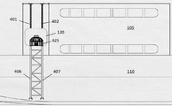
도 5a는, 커서 프레임 조립체(115)의 세부 도면을 예시한다. 도 5a에 예시된 바와 같이, 커서 프레임 조립체(115)는, 모듈(105)의 최상부로부터 개구부(120)를 지나 선체(110)의 용골 레벨까지 연장되는 트랙들(401, 402)을 포함한다. 즉, 트랙(401) 및 트랙(402)의 상부 부분은 모듈(105)에 부착되는 한편, 트랙(401) 및 트랙(402)의 하부 부분은 선체(110)에 부착된다. 트랙들(401, 402)은, 모듈(105) 및/또는 선체(110)에 용접 또는 못으로 고정됨(nailed)으로써, 다양한 방법들을 이용하여 모듈(105) 및 선체(110)에 부착될 수 있다. 커서 프레임 조립체(115)는 또한, 트랙들(401, 402)과 각각 슬라이딩가능하게 맞물리는 안내 레일들(406, 407)을 포함한다. 즉, 안내 레일들(406, 407)은, 이러한 안내 레일들이 트랙들(401, 402)의 전체 길이를 따라 미끄러질 수 있도록 배열된다. 본 발명의 실시예들에 따르면, 트랙들(401, 402)의 상부 부분은 모듈(105)의 최상부로부터 개구부(120)의 최상부까지 연장되는 한편, 트랙들(401, 402)의 하부 부분은 개구부(120)의 바닥부로부터 선체(110)를 가로질러 선박(100)의 용골까지 수직 하방으로 연장된다. 즉, 트랙들(401, 402)은 개구부(120)의 해치(hatch) 또는 문을 가로질러 연장되지 않는다. FIG. 5A illustrates a detailed view of the
도 5a는 또한, 안내 레일(406)의 길이가 트랙(401)의 전체 길이보다 짧은 것, 및 안내 레일(407)의 길이가 트랙(402)의 전체 길이보다 짧은 것을 예시한다. 이것은, 안내 레일들(406, 407)이 이용되지 않는 경우 트랙들(401, 402)을 따라 수축할 수 있고, ROV가 개구부(120)로부터 배치되는 경우 이러한 트랙들을 따라 하방으로 연장될 수 있게 하기 위함이다. 본 발명의 실시예들에서, 안내 레일들(406, 407)의 길이는, 이러한 안내 레일들의 길이가 선박(100) 상의 모듈(105)의 높이와 동일하도록 설계된다. 이것은, 안내 레일들이 수축되는 경우, 안내 레일들의 어떠한 부분도 선박(100)의 갑판보다 낮게 위치되지 않아서, 선박(100)이 이동 중일 때 바다의 표면이 안내 레일들과 접촉할 확률을 감소시킬 것을 보장하기 위함이다. 5A also illustrates that the length of the
트랙들(401, 402)에는, 이들의 하측 단부들에 브레이스들(braces)(416, 417)이 각각 제공된다. 안내 레일들(406, 407)이 완전히 배치되는 경우, 브레이스들(416, 417)은 이러한 안내 레일들을 지지할 것이다. 안내 레일들(406, 407)이 우발적으로 모듈(105)의 최상부로부터 배치되는 경우, 브레이스들(416, 417)은 안내 레일들(406 및 407)에 대한 지지를 제공할 것이다. 이것은, 이러한 자유 낙하되는 안내 레일들이 선박(100)의 다른 부분들을 손상시키지 않을 것을 보장한다. 예를 들어, 이러한 안내 레일들을 하강시키기 위해 이용되는 윈치 또는 크레인이 부러지면, 이러한 브레이스들은 안내 레일들이 아래의 바다로 추락하는 것을 방지할 것이다.
모듈(105)의 상부 섹션 근처에 제공되는 고정 구조물들(411, 412)은, 안내 레일들(406, 407)이 수축 위치인 경우 안내 레일들(406, 407)을 제자리에 단단하게 홀딩하기 위해 이용된다. 고정 구조물들(411, 412)이 모듈(105)의 상부 섹션에 위치되는 주 이유는, 커서 프레임 조립체 시스템(115)의 조작자들이 이러한 고정 구조물들을 동작시키기 위해 더 용이한 접근을 가질 수 있게 하기 위함이다. 또한, 안내 레일들(406, 407)은 통상적으로 모듈(105)의 상부 표면에 제공되는 크레인 또는 윈치를 이용하여 상승 또는 하강되기 때문에, 크레인 또는 윈치에 인접하게 위치되어 고정 구조물들(411, 412)을 각각 이용하여 안내 레일들(406, 407)을 제자리에 고정시킬 조작자가 통상적으로 존재할 것이다.The
도 5a에 예시된 바와 같이, 안내 레일(406)은 가로대(420)를 통해 안내 레일(407)에 연결된다. 특히, 가로대(420)는, 가로대(420)가 안내 레일들(406, 407) 둘 모두에 수직이 되는 방식으로 연결된다. 거친 환경 조건들에서, 안내 레일들(406, 407)이 연장 위치에 있을 때 강한 토크 힘(torque force)들 및 강한 굽힘력(bending force)들이 이러한 안내 레일들에 대해 작용하여; 이러한 안내 레일들이 휘어지고 회전되게 하고, 안내 레일들과 이들 각각의 트랙들 사이의 연결을 변형시킨다. 안내 레일들(406, 407) 둘 모두에 수직인 가로대(420)는 안내 레일들(406, 407) 상에 작용하는 토크 및 굽힘력들을 흡수할 수 있어서, 커서 프레임 조립체(115)가 가장 거친 날씨 조건들 하에서도 활용되거나 완전히 연장되도록 허용한다. 당업자는, 가로대(420)가 안내 레일들(406, 407) 둘 모두에 대해 정확하게 90°일 필요가 없음을 인식할 것이다. 가로대(420)가 안내 레일들(406, 407) 둘 모두에 실질적으로 수직인 한, 가로대(420)는 토크 힘들을 분산시키는 자신의 기능을 수행할 수 있을 것이다. As illustrated in FIG. 5A, the
본 발명의 실시예들에서, 커서 프레임 조립체(115)는 안내 레일들(406, 407)을 연결시키는 한 개 이상의 가로대를 가질 수 있다. 이러한 추가적인 가로대는 도 5a에 가로대(422)로서 예시된다. 당업자는, 가로대들이 안내 레일들(406, 407) 둘 모두에 수직 또는 실질적으로 수직이 되도록 연결되면, 임의의 수의 이러한 가로대들이 안내 레일(406)을 안내 레일(407)에 연결시키도록 이용될 수 있음을 인식할 것이다. 본 발명의 추가적인 실시예들에 따르면, 추가적인 가로대가 제공되어, 안내 레일들(406, 407)에 대한 강한 토크 및 굽힘력들의 인가를 추가로 분산시킬 수 있다. 특히, 가로대는 안내 레일(407)에 연결된 가로대(420)의 단부에 연결될 수 있는 한편, 그 가로대의 다른 단부는, 안내 레일(406)에 연결된 가로대(422)의 단부에 연결될 수 있다. 이러한 가로대는 도 5a에 가로대(421)로서 예시된다. 가로대(421)는, 가로대들(420, 422)에 인가될 수 있는 수직 힘들의 흡수를 보조하여, 이러한 2개의 평행한 가로대들의 구조 및 완전성(integrity)이 가장 거친 동작 조건들 하에서도 위협되지 않을 것을 보장한다. 오직 가로대들(420-422)에 대해서만 참조되지만, 당업자는, 본 발명을 벗어남이 없이, 커서 프레임 조립체(115)의 길이에 걸쳐 임의의 수의 가로대들 또는 이러한 3개의 가로대들의 임의의 조합이 이용될 수 있음을 인식할 것이다. In embodiments of the present invention, the
본 발명의 추가적인 실시예들에 따르면, 커서 프레임 조립체(115)의 안정성 및 핸들링은 직사각형 단면들을 갖는 가로대들을 선택함으로써 개선될 수 있다. 직사각형 형상의 가로대들을 선택함으로써, 이것은, 커서 프레임 조립체(115)에 더 안정된 베이스를 효과적으로 제공하여, 안내 레일들이 거친 날씨 조건들에서 연장되는 경우 안내 레일들 및 트랙들에 인가될 수 있는 굽힘력들에 저항하게 한다. 이것은, 이러한 형상이 가로대들에 의해 안내 레일들에 걸친 토크 힘들의 균등한 분산을 강화하여, 커서 프레임 조립체(115)가 구조적으로 손상되는 것을 방지하기 때문이다. According to further embodiments of the present invention, the stability and handling of the
커서 프레임이 이용되지 않는 경우, 또는 안내 레일들(406, 407)이 수축 위치에 있는 경우, ROV를 수용하기 위한 캐리지 및 ROV 자체는 모듈(105) 내에 위치될 것이다. 이러한 캐리지의 예는 도 5b에 캐리지(425)로서 예시된다. 캐리지(425)는, 스테인레스 스틸로 완전히 제조되는 커서를 포함할 수 있고, 커서는 뒤집힌 그릇 형상 또는 새장 형상이어서, 커서의 상부 곡선 부분이 ROV를 둘러쌀 수 있다. If the cursor frame is not used, or if the
동작 시에, 캐리지(425)는 오직, 이러한 안내 레일들이 바다로 연장된 후 그리고 개구부(120)를 가로지른 해치가 제거된 후에만 안내 레일들(406, 407)에 부착될 것이다. 본 발명의 실시예들에 따르면, 바다로 배치되는 ROV는 먼저 캐리지(425)에 로딩된다. 그 다음, 모듈(105)의 내부로부터 ROV와 함께 캐리지(425)를 안내 레일들(406, 407) 상으로 옮기기 위해 A-프레임(A-frame)이 활용된다. 캐리지(425)가 이러한 안내 레일들 위의 위치로 옮겨지면, A-프레임은 캐리지(425)를 안내 레일들(406, 407) 상으로 하강시켜, 캐리지(425)의 측면들에 제공된 부착부들이 이러한 안내 레일들과 맞물릴 수 있다. 캐리지(425) 상의 부착부들이 안내 레일들과 단단하게 맞물리면, 그 다음, A-프레임은 캐리지(425)를 바다로 하강시키는 것을 계속할 것이다. 캐리지(425)는 안내 레일들(406, 407)을 따른 제한된 경로를 따라 이동할 것이어서, 선박(100)이 격렬하게 히빙(heaving) 및/또는 로킹(rocking)될 수 있더라도 또는 캐리지(425)가 이러한 전체 프로세스에 걸쳐 거친 바람에 흔들리고 있더라도, 캐리지(425)는 선체(110)에 대해 자유롭게 흔들리지 않을 것을 보장한다.In operation, the
A-프레임이 캐리지(425)를 바다로 하강시키면, 그 다음, 캐리지(425) 내에 포함된 ROV가 자신의 수중 동작들을 수행하도록 배치될 수 있다. 그 다음, A-프레임은, 캐리지(425)를 안내 레일들(406, 407)을 따라 상방으로, 이러한 안내 레일들의 최상부까지 캐리지(425)가 올려질 때까지 상승시킴으로써, 비어 있는 캐리지(425)를 바다로부터 상승시킬 것이다. 그 다음, ROV가 자신의 수중 동작들을 완료할 때까지, 분리된 캐리지는 저장을 위해 모듈(105)의 내부로 다시 옮겨진다. ROV가 자신의 드릴링 동작들을 완료한 경우, 캐리지(425)는 앞서 설명된 바와 같이 바다로 하강될 것이다. 그 다음, ROV는 캐리지(425)와 도킹할 것이고, A-프레임을 이용하여 ROV를 포함하는 캐리지(425)는 바다로부터 상승될 것이다. A-프레임이 안내 레일들로부터 캐리지(425)를 상승시킨 후, ROV와 함께 있는 캐리지는 저장을 위해 모듈(105)의 내부로 이동된다.Once the A-frame has lowered the
도 6은, 안내 레일들(406, 407)이 완전히 연장되고 캐리지(425)가 ROV를 배치한 후의 커서 프레임 조립체(115)를 예시한다. 커서 프레임 조립체(115)의 안내 레일들(406 및 407)이 완전히 연장된 후, 캐리지(425)는 선박(100)의 용골 레벨 근처에 또는 해수면 바로 아래에 위치될 것이다. 이것은, 캐리지(425)로부터 바다로 ROV의 배치를 용이하게 한다. 바다 조건들이 거칠고 파도가 치는 경우라도, 그리고 강한 돌풍이 존재하는 경우라도, 캐리지(425)가 커서 프레임 조립체(115)에 의해 견고하게 홀딩될 것이기 때문에 ROV는 여전히 캐리지(425)로부터 진수될 수 있을 것이다.Figure 6 illustrates the
도 7은, C-형상 안내 레일(406) 및 그의 대응하는 트랙(401)의 확대 단면도를 예시한다. 도시된 바와 같이, 트랙(401)은, 더 넓은 베이스 부분(701) 및 베이스 부분(701)으로부터 돌출된 더 좁은 블레이드 부분(702)을 포함한다. 이것은, 트랙(406)이 T-형상 단면 구조를 갖게 한다. 트랙(401)의 상부 절반에 대해, 블레이드 부분(702)은, 모듈(105)에 부착되는 트랙(401)의 섹션이고, 트랙(401)의 하부 절반의 경우, 블레이드 부분(702)은 모듈(105) 부분 및 선체(110) 부분에 부착되는 트랙(401)의 섹션이다. C-형상 안내 레일(406)이 T-형상 트랙(401)에 슬라이딩가능하게 맞물리는 방식으로 인해, 안내 레일(406)의 이동은 오직 트랙(401)의 길이를 따른 슬라이딩 이동들로 제한된다. 트랙(401)의 베이스 부분(701)은 안내 레일(406)의 측면들과 맞물려서, 안내 레일(406)이 트랙(401)에 대해 수평으로 이동하는 것을 방지한다. 유사하게, 안내 레일(406)의 엣지들(705, 706)은 베이스 부분(701)과 맞물려서, 안내 레일(406)이 베이스 부분(701)의 표면(701a)으로부터 떨어지는 것을 방지한다. Figure 7 illustrates an enlarged cross-sectional view of the C-shaped
트랙(402)은 또한, 더 넓은 베이스 부분, 및 그 베이스 부분으로부터 돌출되는 더 좁은 블레이드 부분을 가질 것이다. 트랙(402)의 상부 절반은 블레이드 부분(702)을 통해 모듈(105)에 부착될 것이고, 트랙(402)의 하부 절반은 블레이드 부분(702)을 통해 모듈(105) 부분 및 선체(110) 부분에 부착될 것이다. C-형상 안내 레일(407)이 트랙(402)에 슬라이딩가능하게 맞물리는 방식으로 인해, 안내 레일(407)의 이동은 오직 트랙(402)의 길이를 따른 슬라이딩 이동들로 제한된다. 트랙(402)의 베이스 부분은 안내 레일(407)의 측면들과 맞물려서, 안내 레일(407)이 트랙(402)에 대해 수평으로 이동하는 것을 방지한다. 유사하게, 안내 레일(407)의 엣지들은 트랙(402)의 베이스 부분과 맞물려서, 안내 레일(407)이, 안내 레일(407)과 마주보는 베이스 부분의 표면으로부터 떨어지는 것을 방지한다. 앞서 설명된 구성들은, 안내 레일들이 이들 각각의 트랙들에 단단하게 부착되는 것을 보장한다. 이것은, 안내 레일들의 이동이 오직 이들 각각의 트랙들을 따른 슬라이딩 이동들로만 제한되기 때문에, 거친 날씨에서도 커서 조립체(115)가 활용되도록 허용한다.
도 8은, 고정 구조물들(411, 412)의 확대도를 예시한다. 특히, 고정 구조물(411)은, 모듈(105)에 부착되는 브래킷들(801, 802, 803)을 포함한다. 도 8에 예시된 바와 같이, 브래킷(803)은 안내 레일(406)의 일 측면 상에 제공되고, 브래킷(802)은 안내 레일(406)의 반대 측면 상에 제공되는 한편, 브래킷(801)은 안내 레일(406)로부터 가장 먼 곳에 제공된다. 고정 구조물(411)은 또한, 래치가 제공되는 고정 부재(811)를 포함한다. 브래킷들(801-803) 및 안내 레일(406)의 개구부를 통과하는 고정 부재(811)는, 안내 레일(406)이 수축 위치에 있는 경우 안내 레일(406)을 제자리에 홀딩하기 위해 이용된다. 이 위치에서, 고정 부재(811)에 부착되는 래치는 상부 표면(105b) 상의 커넥터에 부착되어, 고정 부재(811)의 추가적인 이동을 방지할 것이다. 안내 레일(406)이 연장되는 경우, 고정 부재(811)는 브래킷(803) 및 안내 레일(406)의 개구부로부터 후퇴하여, 안내 레일(406)이 트랙(401)의 길이를 따라 아래로 하강되도록 허용할 것이다. Fig. 8 illustrates an enlarged view of the fixing
유사하게, 도 8에 예시된 바와 같이, 고정 구조물(412)은, 모듈(105)에 부착되는 브래킷들(804, 805, 806)을 포함한다. 볼 수 있는 바와 같이, 브래킷(804)은 안내 레일(407)의 일 측면 상에 제공되고, 브래킷(805)은 안내 레일(407)의 반대 측면 상에 제공되는 한편, 브래킷(806)은 안내 레일(407)로부터 가장 먼 곳에 제공된다. 고정 구조물(412)은 또한, 래치가 제공되는 고정 부재(812)를 포함한다. 브래킷들(804-806) 및 안내 레일(407)의 개구부를 통과하는 고정 부재(812)는, 안내 레일(407)이 수축 위치에 있는 경우 안내 레일(407)을 제자리에 홀딩하기 위해 이용된다. 이 위치에서, 고정 부재(812)에 부착되는 래치는 상부 표면(105b) 상의 커넥터에 부착되어, 고정 부재(812)의 어떠한 추가적인 이동을 방지할 것이다. 안내 레일(407)이 연장되는 경우, 고정 부재(812)는 브래킷(804) 및 안내 레일(407)의 개구부로부터 후퇴하여, 안내 레일(407)이 트랙(402)의 길이를 따라 아래로 하강되도록 허용할 것이다. 본 발명의 실시예들에서, 고정 부재들(811, 812)은, 안내 레일들(406, 407)의 하중을 각각 지지하기에 충분한 구조적 강도를 갖는 금속 또는 강철 막대일 수 있다. Similarly, as illustrated in FIG. 8, the
도 9는 안내 레일(407)의 측면도를 예시한다. 이러한 측면도는 패드-아이(pad-eye)(901) 및 개구부(905)를 예시하고, 둘 모두는 안내 레일(407)의 상측 단부 근처에 제공된다. 패드-아이(901)에는 개구부(906)가 제공되고, 개구부(906)는, 패드-아이(901)를 윈치 또는 크레인에 연결시키기 위한 디바이스 또는 후크를 수용하기 위해 이용된다. 안내 레일(407)의 개구부(905)에 대해, 이러한 개구부는, 안내 레일(407)이 수축 위치에 고정되는 경우 고정 부재(812)를 수용하기 위해 이용된다. 유사하게, 도 9에는 예시되지 않았지만, 안내 레일(406)에도 고정 부재(811)를 수용하기 위한 패드-아이 및 개구부가 제공된다. 안내 레일(406)에 제공되는 패드-아이는 또한, 패드-아이를 윈치 또는 크레인에 연결시키기 위한 디바이스를 수용하기 위한 개구부를 가질 것이다. 안내 레일들(406, 407)에 연결되는 윈치 또는 크레인은 통상적으로 표면(105b) 상에 제공될 것이고, 안내 레일들(406, 407)을 요구에 따라 상승 또는 하강시키기 위해 이용된다. 본 발명의 실시예들에서, 안내 레일들을 상승 또는 하강시키기 위해 표면(105b) 상에 제공되는 윈치는 일정 장력 타입(constant tension type)일 수 있다. 이것은, 윈치가 일정 장력으로 안내 레일들에 연결된 와이어를 유지하여, 안내 레일들이 하강되는 속력을 제어할 수 있음을 의미한다. 이것은, 안내 레일들이 특정 속력보다 빨리 하강되지 않을 수 있는 것을 보장하기 때문에 안전 이유에서 유리하다. Fig. 9 illustrates a side view of the
도 10은 캐리지(425)의 측면도를 예시하고, 도 11은 캐리지(425)의 정면도를 예시한다. 캐리지(425)의 일 측면 상에 제공되는 연결 디바이스(1005)는, 캐리지(425)가 안내 레일(407) 상으로 하강되는 경우 안내 레일(407)과 슬라이딩가능하게 맞물리도록 이용된다. 유사하게, 캐리지(425)의 다른 측면 상에 제공되는 연결 디바이스(1006)는, 캐리지(425)가 안내 레일(406) 상으로 하강되는 경우 안내 레일(406)과 슬라이딩가능하게 맞물리도록 이용된다. 본 발명의 실시예들에 따르면, 연결 디바이스들(1005, 1006)은 캐리지 안내부 또는 임의의 다른 타입의 유사한 구조물들을 포함할 수 있다. Fig. 10 illustrates a side view of the
상기 내용은, 연장가능하고 수축가능한 커서 프레임 조립체를 갖는 선박의 설명이다. 당업자들은 하기 청구항들에서 기술되는 바와 같이 본 발명의 대안적 실시예들을 설계할 수 있을 것임이 예상된다.The above is a description of a vessel having an extendable and retractable cursor frame assembly. It is contemplated that those skilled in the art will be able to design alternative embodiments of the invention as described in the following claims.
Claims (10)
각각 베이스 부분 및 베이스 부분으로부터 돌출되는 블레이드 부분을 갖되, 각각의 상측 절반은 상기 블레이드 부분을 통해 상기 선박의 선체 상측에 제공되는 모듈에 부착되고, 각각의 하측 절반은 상기 블레이드 부분을 통해 상기 선박의 선체에 부착되는 제 1 트랙 및 제 2 트랙;
상기 제 1 트랙과 슬라이딩 가능하게 맞물리되, 상기 제 1 트랙의 길이보다 짧은 길이를 갖는 제 1 C-형상 안내 레일 및 상기 제 2 트랙과 슬라이딩가능하게 맞물리되, 상기 제 2 트랙의 길이보다 짧은 길이를 갖는 제 2 C-형상 안내 레일;
상기 제 1 C-형상 안내 레일을 고정시키기 위해 상기 제 1 트랙의 제 1 단부에 인접한 모듈 상에 제공되는 제 1 고정 구조물;
상기 제 2 C-형상 안내 레일을 고정시키기 위해 상기 제 2 트랙의 제 1 단부에 인접한 모듈 상에 제공되는 제 2 고정 구조물; 및
상기 제 1 C-형상 안내 레일을 완충(buffering)시키기 위해 상기 제 1 트랙의 제 2 단부에 제공되는 제 1 브레이스(brace) 및 상기 제 2 C-형상 안내 레일을 완충시키기 위해 상기 제 2 트랙의 제 2 단부에 제공되는 제 2 브레이스;를 포함하는 것을 특징으로 하는 연장가능하고 수축가능한 커서 프레임 조립체를 갖는 선박.A vessel having an extendable and retractable cursor frame assembly,
Each upper half being attached to a module provided on the hull of the ship via the blade portion and each lower half being attached to a portion of the vessel through the blade portion, A first track and a second track attached to the hull;
A first C-shaped guide rail slidably engaged with the first track and having a length shorter than the length of the first track and a second C-shaped guide rail slidably engaged with the second track, A second C-shaped guide rail having a short length;
A first securing structure provided on a module adjacent the first end of the first track for securing the first C-shaped guide rail;
A second securing structure provided on the module adjacent the first end of the second track for securing the second C-shaped guide rail; And
A first brace provided on a second end of said first track for buffering said first C-shaped guide rail and a second brace provided on said second track for buffering said second C- And a second brace provided on the second end of the second brace.
상기 제 1 및 제 2 C-형상 안내 레일들의 길이는 상기 선박의 선체 상측의 상기 모듈의 높이와 동일한 것을 특징으로 하는 연장가능하고 수축가능한 커서 프레임 조립체를 갖는 선박.The method according to claim 1,
Wherein the length of the first and second C-shaped guide rails is equal to the height of the module above the hull of the ship.
상기 제 1 고정 구조물은,
상기 제 1 트랙의 제 1 단부의 제 1 측면에 제공되는 제 1 브래킷;
상기 제 1 트랙의 제 1 단부의 제 2 측면에 제공되는 제 2 브래킷;
상기 제 1 C-형상 안내 레일을 상기 모듈에 고정시키기 위해, 상기 제 1 C-형상 안내 레일의 제 1 단부에 제공되는 개구부 및 상기 제 1 및 제 2 브래킷들을 통과하는 고정 부재;를 포함하는 것을 특징으로 하는 연장가능하고 수축가능한 커서 프레임 조립체를 갖는 선박.The method according to claim 1,
The first fixing structure includes:
A first bracket provided on a first side of the first end of the first track;
A second bracket provided on a second side of the first end of the first track;
An opening provided in the first end of said first C-shaped guide rail and a securing member passing through said first and second brackets for securing said first C-shaped guide rail to said module Wherein the vessel has an extendible and retractable cursor frame assembly.
상기 제 2 고정 구조물은,
상기 제 2 트랙의 제 1 단부의 제 1 측면에 제공되는 제 3 브래킷;
상기 제 2 트랙의 제 1 단부의 제 2 측면에 제공되는 제 4 브래킷;
상기 제 2 C-형상 안내 레일을 상기 모듈에 고정시키기 위해, 상기 제 2 C-형상 안내 레일의 제 1 단부에 제공되는 개구부 및 상기 제 3 및 제 4 브래킷들을 통과하는 고정 부재;를 포함하는 것을 특징으로 하는 연장가능하고 수축가능한 커서 프레임 조립체를 갖는 선박.The method according to claim 1,
The second fixing structure includes:
A third bracket provided on a first side of the first end of the second track;
A fourth bracket provided on a second side of the first end of the second track;
And a fixing member passing through the third and fourth brackets and an opening provided at the first end of the second C-shaped guide rail for securing the second C-shaped guide rail to the module Wherein the vessel has an extendible and retractable cursor frame assembly.
상기 제 1 및 제 2 C-형상 안내 레일들을 상승 또는 하강시키기 위해 상기 모듈의 상측 표면 상에 제공되는 윈치(winch)를 더 포함하는 것을 특징으로 하는 연장가능하고 수축가능한 커서 프레임 조립체를 갖는 선박.The method according to claim 1,
Further comprising a winch provided on an upper surface of said module for raising or lowering said first and second C-shaped guide rails. ≪ Desc / Clms Page number 13 >
상기 윈치는 일정 장력 타입 윈치인 것을 특징으로 하는 연장가능하고 수축가능한 커서 프레임 조립체를 갖는 선박.6. The method of claim 5,
Characterized in that the winch is a constant tension type winch.
제 1 가로대(crosspiece)가 상기 제 1 C-형상 안내 레일을 상기 제 2 C-형상 안내 레일에 연결시키고, 상기 제 1 가로대는 상기 제 1 및 제 2 C-형상 안내 레일들에 수직이 되도록 제공되는 것을 특징으로 하는 연장가능하고 수축가능한 커서 프레임 조립체를 갖는 선박.The method according to claim 1,
A first crosspiece connects the first C-shaped guide rail to the second C-shaped guide rail, and the first crossbar is provided to be perpendicular to the first and second C-shaped guide rails Wherein the vessel frame has an elongate and retractable cursor frame assembly.
제 2 가로대가 상기 제 1 C-형상 안내 레일을 상기 제 2 C-형상 안내 레일에 연결시키고, 상기 제 2 가로대는 상기 제 1 가로대와 평행이 되도록 제공되는 것을 특징으로 하는 연장가능하고 수축가능한 커서 프레임 조립체를 갖는 선박.8. The method of claim 7,
Characterized in that a second crossbar connects said first C-shaped guide rail to said second C-shaped guide rail and said second crossbar is provided to be parallel to said first crossbar. A ship having a frame assembly.
제 3 가로대가 상기 제 1 C-형상 안내 레일을 상기 제 2 C-형상 안내 레일에 연결시키고, 상기 제 3 가로대의 제 1 단부는, 상기 제 1 C-형상 안내 레일에 연결되는 상기 제 1 가로대의 단부에 연결되고, 상기 제 3 가로대의 제 2 단부는, 상기 제 2 C-형상 안내 레일에 연결되는 상기 제 2 가로대의 단부에 연결되는 것을 특징으로 하는 연장가능하고 수축가능한 커서 프레임 조립체를 갖는 선박.9. The method of claim 8,
A third crossbar connects the first C-shaped guide rail to the second C-shaped guide rail, and a first end of the third crossbar is connected to the first cross- And a second end of the third crossbar is connected to an end of the second crossbar connected to the second C-shaped guide rail, wherein the second end of the third crossbar is connected to the end of the second crossbar Ship.
원격무인장비(Remotely Operated Vehicle)를 수용하기 위한 캐리지(carriage);
상기 캐리지의 제 1 측면을 상기 제 1 C-형상 안내 레일에 슬라이딩가능하게 맞물리게 하기 위한 제 1 캐리지 안내부; 및
상기 캐리지의 제 2 측면을 상기 제 2 C-형상 안내 레일에 슬라이딩가능하게 맞물리게 하기 위한 제 2 캐리지 안내부;를 더 포함하는 것을 특징으로 하는 연장가능하고 수축가능한 커서 프레임 조립체를 갖는 선박.The method according to claim 1,
A carriage for receiving a remotely operated vehicle;
A first carriage guide for slidably engaging a first side of the carriage with the first C-shaped guide rail; And
And a second carriage guide for slidably engaging a second side of the carriage with the second C-shaped guide rail. ≪ Desc / Clms Page number 13 >
Applications Claiming Priority (1)
| Application Number | Priority Date | Filing Date | Title |
|---|---|---|---|
| PCT/SG2015/050067 WO2016163949A1 (en) | 2015-04-10 | 2015-04-10 | A vessel having a retractable cursor frame assembly |
Publications (2)
| Publication Number | Publication Date |
|---|---|
| KR20170134174A true KR20170134174A (en) | 2017-12-06 |
| KR102260109B1 KR102260109B1 (en) | 2021-06-04 |
Family
ID=57072099
Family Applications (1)
| Application Number | Title | Priority Date | Filing Date |
|---|---|---|---|
| KR1020167030908A KR102260109B1 (en) | 2015-04-10 | 2015-04-10 | A vessel having a retractable cursor frame assembly |
Country Status (8)
| Country | Link |
|---|---|
| US (1) | US9988127B2 (en) |
| EP (1) | EP3126214B1 (en) |
| KR (1) | KR102260109B1 (en) |
| CN (1) | CN106458294B (en) |
| DK (1) | DK3126214T3 (en) |
| MY (1) | MY190840A (en) |
| SG (1) | SG11201607578SA (en) |
| WO (1) | WO2016163949A1 (en) |
Families Citing this family (2)
| Publication number | Priority date | Publication date | Assignee | Title |
|---|---|---|---|---|
| CN108995772A (en) * | 2017-06-06 | 2018-12-14 | 赵桂平 | The foldable large ship hanging ladder of cunning hanging with magnetic wheel |
| CN108639260A (en) * | 2018-05-15 | 2018-10-12 | 山东交通学院 | A kind of multi-functional primary and secondary salvor |
Citations (4)
| Publication number | Priority date | Publication date | Assignee | Title |
|---|---|---|---|---|
| US1200986A (en) * | 1916-02-15 | 1916-10-10 | Duncan A Mcdonald | Boat-launching device for ships. |
| WO1983003815A1 (en) * | 1982-04-29 | 1983-11-10 | Zf-Herion-Systemtechnik | Loading device for loads movable with respect to a water body |
| US4442922A (en) * | 1981-03-16 | 1984-04-17 | Towmotor Corporation | Adjustable slider bearing assembly |
| US20100101477A1 (en) * | 2008-10-24 | 2010-04-29 | Oceaneering International, Inc. | System and Method for High Current Recovery Cursor |
Family Cites Families (21)
| Publication number | Priority date | Publication date | Assignee | Title |
|---|---|---|---|---|
| CA204558A (en) * | 1920-10-05 | B. Toth Frank | Sliding ladder for ships | |
| DE349144C (en) * | 1914-07-03 | 1922-02-25 | Mayer Karl | Boat launching device |
| US1587979A (en) * | 1922-04-18 | 1926-06-08 | August T Nelson | Mechanism for lowering boats |
| FR1245836A (en) * | 1959-12-08 | 1960-11-10 | Peene Werft Wolgast Veb | Device applicable to ships, for launching, in particular rafts, lifebuoys and inflatable automatic boats |
| US3168955A (en) * | 1963-07-08 | 1965-02-09 | Richard W Black | Apparatus for lightering cargo vessels |
| US3536023A (en) * | 1968-09-16 | 1970-10-27 | Gen Dynamics Corp | Stabilized system for handling small submarines |
| US3993011A (en) * | 1976-01-08 | 1976-11-23 | Brown & Root, Inc. | Method and apparatus for retrieving, securing, and launching an anchor buoy |
| US4067412A (en) * | 1976-12-23 | 1978-01-10 | Jackson Earle B | Floating ladder |
| DE3317433C1 (en) * | 1983-05-13 | 1984-11-15 | Horst Dipl.-Ing. 3064 Bad Eilsen Honebein | Rescue elevator for ships |
| US4638886A (en) * | 1985-10-21 | 1987-01-27 | Sta-Rite Industries, Inc. | Apparatus for disabling an obstructed lift mechanism |
| GB8920172D0 (en) * | 1989-09-06 | 1989-10-18 | Cooper Peter D | Adjustable powder measure |
| FI86402C (en) * | 1990-10-11 | 1994-10-25 | Macgregor Navire Fin Oy | Lyftanordning Foer fartyg |
| GB2287000B (en) * | 1994-03-01 | 1997-12-17 | Wah Kwok Ching | Barge |
| US5628583A (en) * | 1995-07-26 | 1997-05-13 | Gibson; Randolph P. | Small water vehicle lift |
| US6085683A (en) * | 1998-09-01 | 2000-07-11 | The United States Of America As Represented By The Secretary Of The Navy | Underwater depolyable testing platform |
| US6591770B1 (en) * | 2000-10-23 | 2003-07-15 | St. Croix Marine Products, Inc. | Boating lift |
| AT500378B1 (en) * | 2001-06-13 | 2006-12-15 | Tgw Transportgeraete Gmbh | STACKER UNIT |
| ATE471275T1 (en) * | 2005-08-29 | 2010-07-15 | Itrec Bv | VESSEL HAVING A SYSTEM FOR MOUNTING AND GUIDING UNDERWATER EQUIPMENT |
| CN203127105U (en) * | 2012-12-24 | 2013-08-14 | 江阴市北海救生设备有限公司 | Put-away and releasing structure matched with sliding way boat |
| KR20140006039U (en) * | 2013-05-22 | 2014-12-03 | 현대중공업 주식회사 | Lift for moving personal device of upper deck |
| CN205010429U (en) * | 2014-11-27 | 2016-02-03 | 武汉船舶设计研究所 | Working boat automatic storing device |
-
2015
- 2015-04-10 KR KR1020167030908A patent/KR102260109B1/en active IP Right Grant
- 2015-04-10 SG SG11201607578SA patent/SG11201607578SA/en unknown
- 2015-04-10 CN CN201580028937.2A patent/CN106458294B/en active Active
- 2015-04-10 MY MYPI2016703376A patent/MY190840A/en unknown
- 2015-04-10 EP EP15888631.7A patent/EP3126214B1/en active Active
- 2015-04-10 WO PCT/SG2015/050067 patent/WO2016163949A1/en active Application Filing
- 2015-04-10 DK DK15888631.7T patent/DK3126214T3/en active
- 2015-04-10 US US15/316,109 patent/US9988127B2/en active Active
Patent Citations (4)
| Publication number | Priority date | Publication date | Assignee | Title |
|---|---|---|---|---|
| US1200986A (en) * | 1916-02-15 | 1916-10-10 | Duncan A Mcdonald | Boat-launching device for ships. |
| US4442922A (en) * | 1981-03-16 | 1984-04-17 | Towmotor Corporation | Adjustable slider bearing assembly |
| WO1983003815A1 (en) * | 1982-04-29 | 1983-11-10 | Zf-Herion-Systemtechnik | Loading device for loads movable with respect to a water body |
| US20100101477A1 (en) * | 2008-10-24 | 2010-04-29 | Oceaneering International, Inc. | System and Method for High Current Recovery Cursor |
Also Published As
| Publication number | Publication date |
|---|---|
| WO2016163949A1 (en) | 2016-10-13 |
| SG11201607578SA (en) | 2016-11-29 |
| EP3126214A4 (en) | 2018-03-14 |
| DK3126214T3 (en) | 2019-08-05 |
| EP3126214B1 (en) | 2019-05-22 |
| US20170096194A1 (en) | 2017-04-06 |
| CN106458294B (en) | 2019-07-09 |
| KR102260109B1 (en) | 2021-06-04 |
| MY190840A (en) | 2022-05-12 |
| CN106458294A (en) | 2017-02-22 |
| US9988127B2 (en) | 2018-06-05 |
| EP3126214A1 (en) | 2017-02-08 |
Similar Documents
| Publication | Publication Date | Title |
|---|---|---|
| JP5639557B2 (en) | Ships for transporting and installing offshore structures and methods for transporting and installing offshore structures | |
| CN103917439B (en) | There is the offshore platforms of external post | |
| EP2823105B1 (en) | An offshore system comprising a rig and a cantilever | |
| CN103381879B (en) | Docking facilities for promoting the transfer between ship and Offshore Structures | |
| US9540076B1 (en) | System for launch and recovery of remotely operated vehicles | |
| RU2007117138A (en) | MARINE PLATFORM OF THE MASTING TYPE AND METHOD FOR REMOVING THE TOP HOUSING OF THE PLATFORM FROM THE BOAT MODULE | |
| CN112977714A (en) | Scientific investigation workshop with watertight sea-through moon pool | |
| US20200063530A1 (en) | Apparatus and Method | |
| JP2022542025A (en) | Jack-up platform with mooring system and method for mooring a floating vessel | |
| KR102260109B1 (en) | A vessel having a retractable cursor frame assembly | |
| KR101497442B1 (en) | Apparatus and Method for Launching Life Boat for Offshore Structure | |
| WO2012039619A2 (en) | Vessel comprising a hull with a deck and a cargo area extending in a length direction of the deck | |
| WO2010147478A1 (en) | Device and method for transferring crew and personell between vessels and offshore structures | |
| AU2010216206A1 (en) | Skid beam assembly for loading and transporting large structures | |
| US6279501B1 (en) | Umbilical constraint mechanism | |
| US20180065714A1 (en) | System for transporting objects to ocean structures | |
| CA2951665C (en) | Access support for offshore installations | |
| US4165706A (en) | Submersible vehicle deployment and recovery system for rough water | |
| BR112016025689B1 (en) | VESSEL HAVING A RETRACTABLE CURSOR FRAME SET | |
| ES2965025T3 (en) | Floating structure comprising a mooring system for mooring a second floating structure, and method for mooring the second floating structure | |
| CN220032162U (en) | Slide type recovery device of high sea condition fishing robot | |
| CN216374912U (en) | Supplementary device of laying of deck track of comprehensive investigation ship of ocean science | |
| KR101973083B1 (en) | Offshore structure | |
| KR101885168B1 (en) | Offshore structure | |
| CN116424498A (en) | Economical diversion personnel rope ladder combination device of large LNG ship and use method |
Legal Events
| Date | Code | Title | Description |
|---|---|---|---|
| A201 | Request for examination | ||
| E902 | Notification of reason for refusal | ||
| E701 | Decision to grant or registration of patent right |