KR20170131092A - Apparatus for Driving Washing Machine, Washing Machine Using the Same and Driving Method of Washing Machine - Google Patents
Apparatus for Driving Washing Machine, Washing Machine Using the Same and Driving Method of Washing Machine Download PDFInfo
- Publication number
- KR20170131092A KR20170131092A KR1020160062299A KR20160062299A KR20170131092A KR 20170131092 A KR20170131092 A KR 20170131092A KR 1020160062299 A KR1020160062299 A KR 1020160062299A KR 20160062299 A KR20160062299 A KR 20160062299A KR 20170131092 A KR20170131092 A KR 20170131092A
- Authority
- KR
- South Korea
- Prior art keywords
- pulsator
- driving
- rotor
- washing
- stator
- Prior art date
Links
Images


Classifications
-
- D—TEXTILES; PAPER
- D06—TREATMENT OF TEXTILES OR THE LIKE; LAUNDERING; FLEXIBLE MATERIALS NOT OTHERWISE PROVIDED FOR
- D06F—LAUNDERING, DRYING, IRONING, PRESSING OR FOLDING TEXTILE ARTICLES
- D06F37/00—Details specific to washing machines covered by groups D06F21/00 - D06F25/00
- D06F37/30—Driving arrangements
- D06F37/40—Driving arrangements for driving the receptacle and an agitator or impeller, e.g. alternatively
-
- D06F33/02—
-
- D—TEXTILES; PAPER
- D06—TREATMENT OF TEXTILES OR THE LIKE; LAUNDERING; FLEXIBLE MATERIALS NOT OTHERWISE PROVIDED FOR
- D06F—LAUNDERING, DRYING, IRONING, PRESSING OR FOLDING TEXTILE ARTICLES
- D06F33/00—Control of operations performed in washing machines or washer-dryers
- D06F33/30—Control of washing machines characterised by the purpose or target of the control
- D06F33/44—Control of the operating time, e.g. reduction of overall operating time
-
- D—TEXTILES; PAPER
- D06—TREATMENT OF TEXTILES OR THE LIKE; LAUNDERING; FLEXIBLE MATERIALS NOT OTHERWISE PROVIDED FOR
- D06F—LAUNDERING, DRYING, IRONING, PRESSING OR FOLDING TEXTILE ARTICLES
- D06F33/00—Control of operations performed in washing machines or washer-dryers
- D06F33/30—Control of washing machines characterised by the purpose or target of the control
- D06F33/46—Control of the energy or water consumption
-
- D—TEXTILES; PAPER
- D06—TREATMENT OF TEXTILES OR THE LIKE; LAUNDERING; FLEXIBLE MATERIALS NOT OTHERWISE PROVIDED FOR
- D06F—LAUNDERING, DRYING, IRONING, PRESSING OR FOLDING TEXTILE ARTICLES
- D06F37/00—Details specific to washing machines covered by groups D06F21/00 - D06F25/00
- D06F37/02—Rotary receptacles, e.g. drums
- D06F37/12—Rotary receptacles, e.g. drums adapted for rotation or oscillation about a vertical axis
-
- D—TEXTILES; PAPER
- D06—TREATMENT OF TEXTILES OR THE LIKE; LAUNDERING; FLEXIBLE MATERIALS NOT OTHERWISE PROVIDED FOR
- D06F—LAUNDERING, DRYING, IRONING, PRESSING OR FOLDING TEXTILE ARTICLES
- D06F37/00—Details specific to washing machines covered by groups D06F21/00 - D06F25/00
- D06F37/20—Mountings, e.g. resilient mountings, for the rotary receptacle, motor, tub or casing; Preventing or damping vibrations
- D06F37/24—Mountings, e.g. resilient mountings, for the rotary receptacle, motor, tub or casing; Preventing or damping vibrations in machines with a receptacle rotating or oscillating about a vertical axis
-
- D—TEXTILES; PAPER
- D06—TREATMENT OF TEXTILES OR THE LIKE; LAUNDERING; FLEXIBLE MATERIALS NOT OTHERWISE PROVIDED FOR
- D06F—LAUNDERING, DRYING, IRONING, PRESSING OR FOLDING TEXTILE ARTICLES
- D06F37/00—Details specific to washing machines covered by groups D06F21/00 - D06F25/00
- D06F37/30—Driving arrangements
- D06F37/304—Arrangements or adaptations of electric motors
-
- D06F37/306—
-
- H—ELECTRICITY
- H02—GENERATION; CONVERSION OR DISTRIBUTION OF ELECTRIC POWER
- H02K—DYNAMO-ELECTRIC MACHINES
- H02K16/00—Machines with more than one rotor or stator
-
- D—TEXTILES; PAPER
- D06—TREATMENT OF TEXTILES OR THE LIKE; LAUNDERING; FLEXIBLE MATERIALS NOT OTHERWISE PROVIDED FOR
- D06F—LAUNDERING, DRYING, IRONING, PRESSING OR FOLDING TEXTILE ARTICLES
- D06F2103/00—Parameters monitored or detected for the control of domestic laundry washing machines, washer-dryers or laundry dryers
- D06F2103/24—Spin speed; Drum movements
-
- D—TEXTILES; PAPER
- D06—TREATMENT OF TEXTILES OR THE LIKE; LAUNDERING; FLEXIBLE MATERIALS NOT OTHERWISE PROVIDED FOR
- D06F—LAUNDERING, DRYING, IRONING, PRESSING OR FOLDING TEXTILE ARTICLES
- D06F2103/00—Parameters monitored or detected for the control of domestic laundry washing machines, washer-dryers or laundry dryers
- D06F2103/38—Time, e.g. duration
-
- D—TEXTILES; PAPER
- D06—TREATMENT OF TEXTILES OR THE LIKE; LAUNDERING; FLEXIBLE MATERIALS NOT OTHERWISE PROVIDED FOR
- D06F—LAUNDERING, DRYING, IRONING, PRESSING OR FOLDING TEXTILE ARTICLES
- D06F2105/00—Systems or parameters controlled or affected by the control systems of washing machines, washer-dryers or laundry dryers
- D06F2105/46—Drum speed; Actuation of motors, e.g. starting or interrupting
-
- D06F2202/06—
-
- D06F2204/06—
-
- Y—GENERAL TAGGING OF NEW TECHNOLOGICAL DEVELOPMENTS; GENERAL TAGGING OF CROSS-SECTIONAL TECHNOLOGIES SPANNING OVER SEVERAL SECTIONS OF THE IPC; TECHNICAL SUBJECTS COVERED BY FORMER USPC CROSS-REFERENCE ART COLLECTIONS [XRACs] AND DIGESTS
- Y02—TECHNOLOGIES OR APPLICATIONS FOR MITIGATION OR ADAPTATION AGAINST CLIMATE CHANGE
- Y02B—CLIMATE CHANGE MITIGATION TECHNOLOGIES RELATED TO BUILDINGS, e.g. HOUSING, HOUSE APPLIANCES OR RELATED END-USER APPLICATIONS
- Y02B40/00—Technologies aiming at improving the efficiency of home appliances, e.g. induction cooking or efficient technologies for refrigerators, freezers or dish washers
-
- Y02B40/50—
Abstract
Description
본 발명은 세탁기에 관한 것으로, 구체적으로는 세정도가 높은 강력한 3차원 입체 세탁수류를 형성하기 위하여 펄세이터와 세탁조의 역방향 구동에 의한 상호 반대방향 세탁 수류를 형성할 때 에너지 소모를 최소화할 수 있는 세탁기 구동장치와 이를 구비한 세탁기 및 세탁기 구동방법에 관한 것이다. The present invention relates to a washing machine, and more particularly, to a washing machine capable of minimizing energy consumption when washing water is formed in opposite directions by reverse driving of a pulsator and a washing machine in order to form a powerful three- A washing machine having the same, and a method of driving the washing machine.
한국 공개특허공보 제10-1999-0076570호(특허문헌 1)에 개시된 탈수 겸용 세탁기에서 세탁모터는 저속 고토크 모터 특성을 가지고, 탈수모터는 세탁모터보다 고속 저토크 모터 특성을 가지도록, 상기 세탁모터는 아우터 로터형으로 탈수 모터보다 대직경으로 구성되고, 탈수모터는 이너 로터형으로 구성되어 세탁모터가 외측, 탈수모터가 내측 관계가 되도록 구성되어 있다. The washing machine disclosed in Korean Patent Laid-Open Publication No. 10-1999-0076570 (Patent Document 1) has a washing motor having a low-speed high-torque motor characteristic and a dehydrating motor having a high- The motor is an outer rotor type and has a larger diameter than the dehydrating motor, and the dehydrating motor is configured as an inner rotor type so that the washing motor is outside and the dehydrating motor is inside relation.
상기 특허문헌 1의 세탁기는 세탁모터가 아우터 로터형으로 탈수 모터보다 대직경으로 구성되어 있으나, 8kg 이상의 대용량 세탁기에서 대용량 세탁물을 처리하기에는 구동토크가 부족한 문제가 있다. In the washing machine of Patent Document 1, although the washing motor is of the outer rotor type and has a larger diameter than the dehydrating motor, there is a problem that the driving torque is insufficient to process a large capacity laundry in a large capacity washing machine of 8 kg or more.
더욱이, 상기 특허문헌 1의 세탁기는 탈수 모터보다 대직경으로 구성되고 외측에 배치되어 저속 고토크 모터 특성을 가지는 아우터 로터형의 세탁모터에 의해 교반체를 구동하는 구조를 제안하고 있어, 더 큰 기동토크가 요구되는 회전조를 교반체와 상호 역방향으로 구동시킴에 의해 강한 세탁수류를 구현하기 어려운 문제가 있다. Furthermore, the washing machine disclosed in Patent Document 1 proposes a structure in which the agitator is driven by an outer rotor type washing motor having a larger diameter than the dehydrating motor and disposed on the outer side and having a low speed high torque motor characteristic, There is a problem that it is difficult to realize a strong washing water flow by rotating the rotating tub in which the torque is required in the opposite direction to the stirring member.
따라서, 상기 특허문헌 1의 세탁기는 2개의 구동모터를 사용하여 교반체와 회전조를 독립적으로 구동시킬 수 있는 구조를 개시하고 있으나, 대용량 세탁기에서 고토크를 이용한 다양한 방식의 세탁 수류를 만드는 것은 제안되지 않고 있다.Therefore, although the washing machine disclosed in Patent Document 1 has a structure capable of independently driving the agitator and the rotating drum by using two driving motors, it has been proposed to make various types of washing water using high torque in a large- .
상기 특허문헌 1의 세탁기는 세탁공정시에 탈수모터를 세탁모터와 반대방향 회전의 통전모드로 설정하거나 전기 브레이크에 의해 회전조가 공회전하는 것을 방지한 상태에서 단지 세탁모터에 의한 교반체의 구동에 의해 세탁수류를 형성하고 있어, 대용량 세탁기에 큰 부하의 세탁물을 세탁할 수 있는 보다 강력한 수류(세탁력)를 발생할 수 없다.In the washing machine of Patent Document 1, the dewatering motor is set to the energizing mode for rotating in the direction opposite to the washing motor at the time of the washing process, or by the driving of the stirrer by the washing motor only in a state in which the rotating tub is idly rotated by the electric brake So that a stronger water flow (washing power) capable of washing a large load laundry in a large capacity washing machine can not be generated.
더욱이, 상기 특허문헌 1의 세탁기는 펄세이터(교반체)와 세탁조(회전조)를 서로 반대방향으로 회전시켜서 세정도를 높이는 강한 수류를 형성하려고 할 때, 직경이 작아서 구동 토크가 작은 인너 로터로 많은 세탁물과 물이 채워진 세탁조를 초기 기동하면 인너 로터의 구동 토크 부족으로 초기 기동전류가 과도하게 소모되어 효율 저하가 발생되는 문제가 있다.Furthermore, in the washing machine of Patent Document 1, when the pulsator (stirring body) and the washing tank (rotating bath) are rotated in opposite directions to form a strong water flow which increases three degrees, the inner rotor is small in diameter and small in driving torque When the washing machine is filled with a large amount of laundry and water, the initial starting current is excessively consumed due to insufficient driving torque of the inner rotor, resulting in a reduction in efficiency.
이러한 종래의 전자동 세탁기의 문제점을 고려하여 한국 공개특허공보 제10-2015-0008347호(특허문헌 2)에 더블 로터-더블 스테이터 방식의 쌍동력 구동모터와 유성기어장치를 조합하여, 탈수조와 펄세이터를 동시에 독립적으로 구동시킴에 의해 다양한 세탁 수류를 형성하는 기술이 제안되어 있다.In consideration of the problems of such a conventional automatic washing machine, a double rotor-double stator type bicycle drive motor and a planetary gear unit are combined with a dewatering pump and a pulsator in Korean Patent Laid-Open No. 10-2015-0008347 (Patent Document 2) A plurality of washing water streams are simultaneously and independently driven to thereby form various washing water streams.
상기 특허문헌 2에서는 세탁 행정시에 펄세이터와 세탁조를 서로 동일방향 또는 역방향으로 회전시키는 방법으로 쌍동력에 의한 상호 반대방향 세탁 수류 등을 형성하는 세탁방법을 제안하고 있으나, 소모전류 절감과 세탁기의 효율 상승을 고려한 수류 형성방법은 제안하고 있지 않다.The
특히, 특허문헌 2에서는 세탁 행정시에 쌍동력에 의한 상호 반대방향 세탁 수류를 형성할 때 세탁조를 펄세이터와 서로 다른 방향 및 동일한 속도로 동시에 구동시키는 것은 세탁조를 구동할 때 대전류가 소모되어 에너지 소모가 커지는 문제가 발생할 수 있다.Particularly, in
한편, 단동력을 이용한 종래의 전자동세탁기의 운전방법은 펄세이터를 순방향 회전, 정지, 역방향 회전, 정지를 반복하면서 방향전환에 의해 수직 상승/하강 수류 물살을 발생시켜서 세탁물에 물과 세제가 잘 접촉이 이루어지도록 하고 있다.Meanwhile, a conventional automatic washing machine using a single power generates a vertical rising / falling water stream by repeating forward rotation, stopping, reverse rotation, and stopping of the pulsator to change direction, so that water and detergent .
이 경우, 구동모터로서 A.C. 인덕션 모터를 사용하며, 구동신호의 인가에 따라 미리 설정된 RPM으로 가동시간과 정지시간이 각각 0.5초 내지 2초 범위 내에서 짧은 시간 주기로 가동과 정지를 반복 구동하거나 또는 가동시간 중에 짧은 시간 동안 정지시간을 부여하는 간헐구동방법 등을 사용하고 있다. 이 경우 운전율은 50%를 적용하고 있다.In this case, A.C. Induction motor is used. It is operated by repeatedly starting and stopping in a short time period within a range of 0.5 sec. To 2 sec. In each operation time and stopping time with preset RPM according to application of drive signal, And the like are used. In this case, the operating rate is 50%.
인덕션 모터는 저소음, 저진동 등의 특징이 있으나, 저속에서 저토크 특성을 나타내며 동적 반응이 느린 비동기 전동기이기 때문에 세탁 행정시에 순방향과 역방향으로 회전 방향을 빠르게 전환하면서 강한 세탁 수류를 형성하는 데 어려움이 있다.The induction motor is characterized by low noise and low vibration. However, since it is an asynchronous motor that exhibits a low torque characteristic at low speed and a slow dynamic reaction, it is difficult to form a strong washing water flow while rapidly changing the direction of rotation in forward and reverse directions have.
이에 반해 BLDC 모터는 동적 반응이 빠르고, 낮은 로터 관성을 가지고 있으며, 속도 제어가 용이한 동기 전동기이나, 종래에는 세탁기용 구동장치로서 이러한 BLDC 모터의 특징을 잘 살리는 구동방법이 제안되지 못하였다.On the other hand, the BLDC motor has not been proposed as a synchronous motor which has quick dynamic reaction, low rotor inertia, easy speed control, and a drive device for a washing machine in the past.
따라서, 본 발명은, 상기와 같은 문제점을 해결하기 위해 안출된 것으로, 그 목적은 더블 로터-더블 스테이터 방식의 쌍동력 구동모터를 이용하여, 세정도가 높은 강력한 3차원 입체 세탁수류를 형성하기 위하여 펄세이터와 세탁조의 역방향 구동에 의한 상호 반대방향 세탁 수류를 형성할 때 에너지 소모를 최소화할 수 있는 세탁기 구동장치 및 이를 이용한 세탁기를 제공하는 데 있다.SUMMARY OF THE INVENTION Accordingly, the present invention has been made to solve the above problems, and its object is to provide a three-dimensional washing machine, The present invention provides a washing machine driving apparatus and a washing machine using the washing machine, which can minimize energy consumption when washing water is formed in opposite directions by reverse driving of a pulsator and a washing tub.
본 발명의 다른 목적은 쌍동력을 이용하여 펄세이터와 세탁조를 서로 역방향 구동시에 쌍동력 구동모터의 기동방법과 정지방법을 개선함에 의해 세정력이 높은 강한 와류를 형성할 수 있는 세탁기 구동방법을 제공하는 데 있다. Another object of the present invention is to provide a washing machine driving method capable of forming a strong vortex with high cleaning power by improving the starting method and the stopping method of a bi-motive driving motor when the pulsator and the washing tank are reciprocated by using bi- There is.
본 발명의 또 다른 목적은 BLDC 모터의 특징을 잘 활용할 수 있도록 정지시간보다 가동시간을 충분히 길게 설정하여 운전율을 높이면서 전체적인 세탁시간을 단축하여 전체적인 소비전력을 최소화할 수 있는 세탁기 및 세탁기 구동방법을 제공하는 데 있다. It is still another object of the present invention to provide a washing machine and a washing machine driving method capable of minimizing the overall power consumption by increasing the operating rate and shortening the overall washing time by setting the operating time to be sufficiently longer than the stopping time so as to utilize the characteristics of the BLDC motor .
본 발명의 다른 목적은 상호 반대방향 세탁 수류를 형성할 때, 직경이 작아서 구동 토크가 작은 인너 로터의 자석을 높은 자속밀도를 갖는 희토류계 자석을 채용함에 따라 인너 로터의 구동 토크를 증대시켜서 많은 세탁물과 물이 채워진 세탁조의 초기 기동시에도 무리가 따르지 않는 세탁기 구동장치 및 이를 이용한 세탁기를 제공하는 데 있다.Another object of the present invention is to provide a method of manufacturing a washing machine, which is capable of increasing the driving torque of an inner rotor by using a magnet of an inner rotor having a small diameter and a small driving torque and a rare earth magnet having a high magnetic flux density, And a washing machine using the washing machine, wherein the washing machine is filled with water even when the washing machine is initially started.
본 발명의 또 다른 목적은 구동 토크가 큰 대직경의 아우터 로터로 세탁조를 구동하고, 구동 토크가 작은 소직경의 인너 로터는 희토류계의 고자력 자석을 사용하여 아우터 로터와 유사하게 구동 토크를 증대시켜서 펄세이터를 구동하는 세탁기 구동장치 및 이를 이용한 세탁기를 제공하는 데 있다.Another object of the present invention is to provide a washing machine which drives a washing tub with a large-diameter outer rotor having a large driving torque and a small-diameter inner rotor with a small driving torque that uses a rare earth- And a washing machine using the same.
본 발명의 다른 목적은 구동 토크를 증대시키도록 희토류계의 고자력 자석을 사용하는 소직경의 인너 로터와 구동 토크가 큰 대직경의 아우터 로터의 구동 토크를 동등하게 구현하여 세탁 행정 및 행굼 행정시에 펄세이터와 세탁조를 동시에 구동하여 다양한 세탁 수류 및 헹굼 패턴을 형성할 수 있는 세탁기 구동장치 및 이를 이용한 세탁기를 제공하는 데 있다. It is another object of the present invention to provide an internal rotor having a small diameter and a large-diameter outer rotor using a rare-earth magnet and an outer rotor having a large driving torque, The present invention also provides a washing machine driving apparatus and a washing machine using the same, which can simultaneously form a washing water flow and a rinsing pattern by driving a pulsator and a washing tub at the same time.
본 발명의 제1특징에 따르면, 본 발명은 더블 스테이터에 의해 독립적으로 제어 가능한 인너 로터와 아우터 로터를 구비하고, 선택적으로 인너 로터 출력과 아우터 로터 출력을 발생하는 더블 로터-더블 스테이터 방식의 구동모터; 상기 아우터 로터 출력을 펄세이터에 전달하는 인너 샤프트; 상기 인너 샤프트의 외주에 회전 가능하게 결합되며, 상기 인너 로터 출력을 세탁조에 전달하는 아우터 샤프트; 및 상기 더블 스테이터에 제1 및 제2 구동신호를 독립적으로 인가하여 인너 로터와 아우터 로터를 제어하는 제어유닛을 포함하며, 상기 제어유닛은 세탁 행정시에 상기 펄세이터가 시계방향 및 반시계방향으로 회전방향을 전환할 때 정지시간을 가지며, 상기 세탁조는 펄세이터의 시계방향 및 반시계방향의 구동시간이 종료되기 전에 기동하여 펄세이터의 회전 방향과 반대방향으로 구동이 이루어지도록 제어하는 것을 특징으로 한다. According to a first aspect of the present invention, there is provided a double rotor-double stator type drive motor having an inner rotor and an outer rotor independently controllable by a double stator and selectively generating an inner rotor output and an outer rotor output, ; An inner shaft for transmitting the outer rotor output to the pulsator; An outer shaft rotatably coupled to an outer periphery of the inner shaft and transmitting the output of the inner rotor to a washing tub; And a control unit for independently applying first and second driving signals to the double stator to control the inner rotor and the outer rotor, wherein the control unit controls the pulsator to rotate clockwise and counterclockwise And the washing tub is started before the pulsator's clockwise and counterclockwise driving time ends to drive the pulsator in a direction opposite to the rotational direction of the pulsator. do.
상기 세탁조의 구동은 펄세이터의 정지시간까지 연장되어 구동될 수 있다. The driving of the washing tub may be extended until the pulsator stops.
또한, 상기 세탁조는 펄세이터의 시계방향 및 반시계방향의 기동과 동시에 펄세이터의 회전 방향과 반대방향으로 구동된 후, 펄세이터의 구동시간보다 짧게 구동이 이루어질 수 있다. In addition, the washing tub may be driven in a direction opposite to the rotational direction of the pulsator simultaneously with the clockwise and counterclockwise starting of the pulsator, and then the driving time may be shorter than the pulsator driving time.
더욱이, 상기 펄세이터의 구동시간과 정지시간은 1.5:1 내지 10:1 범위로 설정될 수 있다. Furthermore, the driving time and the stopping time of the pulsator may be set in the range of 1.5: 1 to 10: 1.
상기 펄세이터의 기동 및 정지 동작시에 오버슈팅 구동이 이루어질 수 있으며, 상기 펄세이터의 기동시에 램프-업 구동이 이루어질 수 있다. 또한 상기 펄세이터는 가변속도로 구동될 수 있다.The overshooting driving may be performed during start and stop operations of the pulsator, and the ramp-up driving may be performed at the start of the pulsator. The pulsator may be driven at a variable speed.
상기 펄세이터의 회전방향을 전환하기 위해 전자 브레이크가 이루어지는 시점의 펄세이터의 RPM이 높을수록 정지시간은 증가할 수 있다. 이 경우, 상기 펄세이터의 정지는 아우터 로터를 구동하는 드라이버를 이용하여 전자 브레이크를 실시할 수 있다.The higher the RPM of the pulsator at the time when the electromagnetic brake is made to switch the direction of rotation of the pulsator, the more the stopping time may be increased. In this case, stopping of the pulsator can be performed by using a driver for driving the outer rotor.
또한, 상기 인너 로터의 구동 토크는 아우터 로터의 구동 토크와 동등하게 설정할 수 있으며, 이 경우, 상기 인너 로터는 희토류계 자석을 사용하고, 상기 아우터 로터는 페라이트 자석을 사용할 수 있다.The driving torque of the inner rotor may be set to be equal to the driving torque of the outer rotor. In this case, the inner rotor may use a rare earth magnet, and the outer rotor may use a ferrite magnet.
상기 아우터 로터는 상기 스테이터의 외면에 일정 갭을 두고 배치되며 N극 및 S극이 교대로 배치되는 다수의 제2자석; 상기 제2자석의 배면에 배치되는 제2백요크; 및 상기 제2자석 및 제2백요크를 지지하는 아우터 로터 지지체를 포함할 수 있다. Wherein the outer rotor includes a plurality of second magnets disposed at an outer surface of the stator with a predetermined gap therebetween and having N poles and S poles alternately arranged; A second back yoke disposed on a back surface of the second magnet; And an outer rotor support for supporting the second magnet and the second back yoke.
이 경우, 상기 아우터 로터 지지체는 단면이 컵 형상의 바닥면 중에 상기 스테이터의 인너 및 아우터 스테이터 코일과 대향한 외측평탄부와, 인너 샤프트와 결합이 이루어지는 내측평탄부와, 상기 외측평탄부와 내측평탄부를 연결하는 경사연결부를 포함하고, 상기 외측 평탄부에는 상기 인너 및 아우터 스테이터 코일과 대향한 부분에 각각 인너 및 아우터 스테이터 코일로부터 발생된 열을 외부로 배출하는 제1 및 제2 관통구멍을 구비할 수 있다.In this case, the outer rotor support body preferably has an outer flat portion facing the inner and outer stator coils of the stator in a cup-shaped bottom surface in cross section, an inner flat portion engaged with the inner shaft, Wherein the outer flat portion has first and second through holes for discharging heat generated from the inner and outer stator coils to the outside, respectively, at portions of the outer flat portion opposite to the inner and outer stator coils .
또한, 상기 아우터 로터 지지체는 그의 외주면 및 내주면에 각각 일정한 각도마다 방사방향으로 돌출되어 있는 복수의 방사방향 보강리브; 및 그의 내주면에 원주방향으로 간격을 두고 형성되어 있는 제1 내지 제3 원주방향 보강리브를 포함할 수 있다. Further, the outer rotor support body includes a plurality of radial direction reinforcing ribs protruding radially from the outer circumferential surface and the inner circumferential surface at a predetermined angle, respectively; And first to third circumferential reinforcing ribs formed on the inner circumferential surface thereof at intervals in the circumferential direction.
본 발명의 제2특징에 따르면, 본 발명은 세탁수를 수용하는 외조; 상기 외조의 내부에 회전 가능하게 배치되어 세탁과 탈수가 이루어지는 세탁조; 상기 세탁조 내부에 회전 가능하게 배치되어 세탁 수류를 형성하는 펄세이터; 및 상기 세탁조와 펄세이터를 동시에 또는 선택적으로 구동시키는 상기 세탁기 구동장치를 포함하는 것을 특징으로 하는 세탁기를 제공한다.According to a second aspect of the present invention, there is provided a washing machine comprising: an outer tub for receiving wash water; A washing tub which is rotatably disposed inside the outer tub to perform washing and dehydrating; A pulsator arranged rotatably in the washing tub to form wash water; And a washing machine driving device for simultaneously or selectively driving the washing tub and the pulsator.
본 발명의 제3특징에 따르면, 본 발명은 펄세이터를 제1기간 동안 제1방향으로 회전 구동하는 제1단계; 상기 제1기간이 종료되기 전에 세탁조를 제2기간 동안 상기 제1방향과 반대방향으로 회전 구동하는 제2단계; 상기 제1기간의 경과에 따라 펄세이터를 정지시키는 제3단계; 상기 제1기간의 경과 이후에 상기 제2기간의 경과에 따라 상기 세탁조를 정지시키는 제4단계; 및 상기 제2기간의 경과 이후에 펄세이터의 정지시간이 경과하는 경우, 상기 제1 내지 제4 단계에서 펄세이터와 세탁조의 회전방향을 각각 반대로 설정하여 순차적으로 실행하는 제5단계;를 포함하는 것을 특징으로 하는 세탁기 구동방법을 제공한다.According to a third aspect of the present invention, there is provided a method of driving a pulsator, comprising: a first step of rotationally driving a pulsator in a first direction for a first period; Rotating the washing tub in a direction opposite to the first direction for a second period before the first period ends; A third step of stopping the pulsator according to the elapse of the first period; A fourth step of stopping the washing tub according to the passage of the second period after the lapse of the first period; And a fifth step of, when the stop time of the pulsator has elapsed after the lapse of the second period of time, executing the rotation steps of the pulsator and the washing tub sequentially in the first to fourth steps, respectively, Wherein the washing machine comprises a washing machine.
상기한 바와 같이, 본 발명에서는 더블 로터-더블 스테이터 방식의 쌍동력 구동모터를 이용하여, 펄세이터와 세탁조를 서로 역방향 구동에 의한 세탁 수류를 형성할 때 에너지 소모를 최소화하면서도 세정도가 높은 강력한 3차원 입체 세탁수류를 형성할 수 있다. As described above, in the present invention, when a double-rotor-double stator type bipotal driving motor is used to form a washing water flow by reversing the pulsator and the washing tank to each other, energy consumption is minimized, Dimensional three-dimensional washing water stream.
또한, 본 발명에서는 쌍동력을 이용하여 펄세이터와 세탁조를 서로 역방향 구동시에 쌍동력 구동모터의 기동방법과 정지방법을 개선함에 의해 세정력이 높은 강한 와류를 형성할 수 있다. In addition, in the present invention, a strong vortex with high washing power can be formed by improving the start-up method and the stopping method of the bi-motive driving motor while the pulsator and the washing tank are reciprocated by using bi-motive force.
더욱이, 본 발명에서는 BLDC 모터의 특징을 잘 활용할 수 있도록 정지시간보다 가동시간을 충분히 길게 설정하여 운전율을 높이면서 전체적인 세탁시간을 단축하여 전체적인 소비전력을 최소화할 수 있다. Further, in the present invention, the operation time is set to be sufficiently longer than the stop time so as to utilize the characteristics of the BLDC motor, so that the overall operation time can be shortened and the overall power consumption can be minimized.
또한, 본 발명에서는 쌍동력을 이용하여 펄세이터와 세탁조를 서로 역방향으로 회전시키는 쌍방향 수류 세탁 행정시에 인너 로터와 아우터 로터의 가동시간과 정지시간의 적정한 비율을 설정함에 의해 운전율을 높이고 세탁수류를 개선하여 세탁기의 효율 상승을 도모할 수 있다. Further, in the present invention, by setting a proper ratio of the operation time and the stop time of the inner rotor and the outer rotor in the bidirectional water flow washing operation in which the pulsator and the washing tub are rotated in opposite directions to each other using the bi- So that the efficiency of the washing machine can be increased.
본 발명에서는 구동 토크가 큰 대직경의 아우터 로터로 고토크를 필요로 하는 세탁조를 구동하고, 구동 토크가 작은 소직경의 인너 로터는 희토류계의 고자력 자석을 사용하여 아우터 로터와 유사하게 구동 토크를 증대시켜서 펄세이터를 구동할 수 있다.In the present invention, a small-diameter inner rotor that drives a washing machine that requires a high torque with a large-diameter outer rotor having a large driving torque and a small-diameter inner rotor with a small driving torque uses a rare earth- The pulsator can be driven.
또한, 본 발명에서는 구동 토크를 증대시키도록 희토류계의 고자력 자석을 사용하는 소직경의 인너 로터와 구동 토크가 큰 대직경의 아우터 로터의 구동 토크를 동등하게 구현하여 세탁 행정 및 행굼 행정시에 펄세이터와 세탁조를 동시에 구동하여 상호 반대방향 세탁 수류와 같은 다양한 수류 및 헹굼 패턴을 형성할 수 있다. In addition, in the present invention, the driving torque of a small-diameter inner rotor using a rare-earth-based high magnetic force magnet and the driving torque of a large-diameter outer rotor having a large driving torque are equally implemented in order to increase the driving torque, The pulsator and the washing machine can be driven at the same time to form various water flow and rinse patterns such as washing water in opposite directions.
본 발명에서는 상호 반대방향 세탁 수류를 형성할 때, 직경이 작아서 구동 토크가 작은 인너 로터의 자석을 높은 자속밀도를 갖는 희토류계 자석을 채용함에 따라 인너 로터의 구동 토크를 증대시켜서 많은 세탁물과 물이 채워진 세탁조의 초기 기동시에도 무리가 따르지 않는다.According to the present invention, when forming a washing water in opposite directions, a magnet of an inner rotor having a small diameter and a small driving torque is used as a rare earth magnet having a high magnetic flux density, so that the driving torque of the inner rotor is increased, The initialization of the filled washing machine is not accompanied by any difficulties.
또한, 본 발명에서는 구동 토크가 큰 아우터 로터를 고토크를 필요로 하는 세탁조와 연결하고, 구동 토크가 작은 인너 로터를 저토크에서 구동 가능한 펄세이터와 연결하면서 희토류계 자석을 채용함에 따라 인너 로터의 구동 토크를 증대시켜서 상호 반대방향 세탁 수류와 같은 다양한 수류 및 헹굼 패턴을 형성할 수 있다. Further, in the present invention, since the outer rotor having a large driving torque is connected to the washing tank requiring high torque and the inner rotor having a small driving torque is connected to the pulsator capable of driving at a low torque, It is possible to increase the driving torque and to form various water flow and rinse patterns such as washing water in mutually opposite directions.
또한, 본 발명에서는 토크 변속을 위한 유성기어장치를 제거하여 구조가 간단해짐에 따라 조립 생산성을 높이고 제조비용을 절감할 수 있으며, 토크 변속시에 발생하는 소음을 제거할 수 있다.In addition, according to the present invention, as the structure is simplified by eliminating the planetary gear device for torque transmission, the assembly productivity can be improved, manufacturing cost can be reduced, and noise generated at the time of torque transmission can be removed.
본 발명은 인너 로터와 아우터 로터의 구동 토크를 동등하게 구현함에 의해 대용량 세탁기에도 적용 가능하다.The present invention can be applied to a large-capacity washer by equally realizing the driving torque of the inner rotor and the outer rotor.
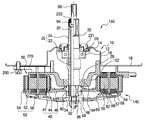
도 1은 본 발명의 제1실시예에 따른 세탁기 구동장치를 구비한 세탁기의 축방향 단면도이다.
도 2는 도 1에 도시된 세탁기 구동장치의 축방향 부분 절단 단면도이다.
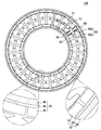
도 3a 내지 도 3d는 각각 도 2에 도시된 아우터 로터의 배면도, 내측면도, 우측면도 및 도 3a의 A-A선 단면도이다.
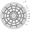
도 4a는 본 발명에 따른 구동모터의 직경방향 단면도이다.
도 4b는 스테이터 조립에 사용되는 스테이터 코어 조립체의 개략 단면도이다.
도 4c는 스테이터 코어를 구성하는 분할 코어의 평면도이다.
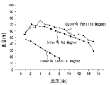
도 5는 인너 로터에 페라이트 자석과 Nd 자석을 사용할 경우 토크와 효율 관계를 비교하여 나타낸 그래프이다.
도 6은 본 발명에 따른 세탁기 제어장치의 블럭 회로도이다.
도 7은 본 발명에 따른 전체적인 세탁기 구동방법을 나타낸 순서도이다.
도 8a 및 도 8b는 본 발명에 따른 상호 반대방향 세탁 수류 형성방법을 나타낸 순서도이다.
도 9 내지 도 12는 각각 본 발명에 따른 상호 반대방향 세탁 수류 형성방법을 구현하기 위한 펄세이터와 세탁조의 RPM 타이밍도이다.
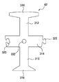
도 13은 본 발명의 제2실시예에 따른 세탁기 구동장치의 축방향 단면도이다. 1 is an axial cross-sectional view of a washing machine having a washing machine driving apparatus according to a first embodiment of the present invention.
2 is an axial sectional cut-away sectional view of the washing machine driving apparatus shown in Fig.
Figs. 3A to 3D are a rear view, an inner side view, a right side view, and a cross-sectional view of the outer rotor of Fig. 3A, respectively, of the outer rotor shown in Fig.
4A is a cross-sectional view in the radial direction of the drive motor according to the present invention.
4B is a schematic cross-sectional view of a stator core assembly used for stator assembly.
4C is a plan view of the divided cores constituting the stator core.
5 is a graph showing a comparison of torque and efficiency when a ferrite magnet and an Nd magnet are used in an inner rotor.
6 is a block circuit diagram of a washing machine control apparatus according to the present invention.
7 is a flowchart illustrating an overall washing machine driving method according to the present invention.
8A and 8B are flowcharts illustrating a method of forming counter-directional washing water streams according to the present invention.
FIGS. 9 to 12 are timing charts of the RPM of the pulsator and the washing tub for implementing the mutually opposing washing water flow forming method according to the present invention, respectively.
13 is an axial sectional view of a washing machine driving apparatus according to a second embodiment of the present invention.
이하, 첨부된 도면을 참조하여 본 발명에 따른 실시예를 상세히 설명한다. 이 과정에서 도면에 도시된 구성요소의 크기나 형상 등은 설명의 명료성과 편의상 과장되게 도시될 수 있다. Hereinafter, embodiments of the present invention will be described in detail with reference to the accompanying drawings. The sizes and shapes of the components shown in the drawings may be exaggerated for clarity and convenience.
도 1 내지 도 4c를 참조하면, 본 발명의 제1실시예에 따른 세탁기는 외형을 이루는 케이스(100)와, 케이스(100)의 내부에 배치되어 세탁수를 수용하는 외조(110)와, 상기 외조(110)의 내부에 회전 가능하게 배치되어 세탁과 탈수를 수행하는 세탁조(120)와, 상기 세탁조(120)의 바닥부에 회전 가능하게 배치되어 세탁 수류를 형성하는 펄세이터(130)와, 상기 세탁조(120)와 외조(110)의 하부에 설치되어 세탁 행정, 헹굼 행정, 풀림 행정 및 탈수 행정 등에 필요한 구동력을 세탁조(120)와 펄세이터(130)에 동시에 또는 선택적으로 제공하는 세탁기 구동장치(150)를 포함한다. 1 to 4C, a washing machine according to a first embodiment of the present invention includes a
상기 세탁기 구동장치(150)는 외조(110)의 하부에 장착되고 인너 로터(40)와 아우터 로터(50)로부터 쌍동력을 발생하는 더블 로터-더블 스테이터 방식의 구동모터(140)와, 상기 구동모터(150)의 인너 로터(40)와 아우터 로터(50)에 의해 제공되는 쌍동력을 받아서 상기 펄세이터(130)와 세탁조(120)에 전달하는 아우터 샤프트(20) 및 인너 샤프트(30)를 포함한다. The washing
구동모터(140)는 도 2에 도시된 바와 같이, 아우터 샤프트(20)와 연결되는 인너 로터(40)와, 인너 샤프트(30)와 연결되는 아우터 로터(50)와, 인너 로터(40)와 아우터 로터(50) 사이에 공극을 두고 배치되어 인너 로터(40)와 아우터 로터(50)를 회전 구동시키는 스테이터(60)를 포함한다. 상기 스테이터(60)는 인너 로터(40)와 아우터 로터(50)를 각각 독립적으로 구동시키는 더블 스테이터 구조를 갖는다.2, the driving
이에 따라 스테이터(60)는 인너 로터(40)와 아우터 로터(50)를 도 6에 도시된 제1 및 제2 드라이버(530,540)를 이용하여 선택적/독립적으로 구동할 수 있도록 도 4a와 같이 아우터 스테이터(60b)와 인너 스테이터(60a)를 구비하고 있다. 이하에 후술하는 실시예 설명에서는 아우터 스테이터와 인너 스테이터를 일체형으로 구성한 것을 예시하고 있으나, 분리된 구조로 이루어지는 것도 가능하다.4A so that the
상기 아우터 샤프트(20)는 인너 샤프트(30)의 외주에 회전 가능하게 결합되며, 일단이 인너 로터(40)의 중심에 연결되는 제1샤프트(22)와 일단이 제1샤프트(22)의 타단에 결합되며 타단이 세탁조(120)에 결합되는 제2샤프트(24)를 포함한다. 이 경우 제1샤프트(22)와 제2샤프트(24)는 일체형으로 구성될 수 있다.The
인너 샤프트(30)의 외주면과 제1샤프트(22)의 내주면 사이에는 원통 형태의 제1슬리브 베어링(80)이 설치되고, 제2샤프트(24)의 상단 내면에는 제2슬리브 베어링(82)이 설치되어 인너 샤프트(30)를 회전 가능하게 지지한다. A first sleeve bearing 80 in the form of a cylinder is provided between the outer circumferential surface of the
제1샤프트(22)의 외면에는 인너 로터(40)의 인너 로터 지지체(46)가 부싱(48)을 통하여 연결되는 제1연결부(90)가 형성되고, 인너 샤프트(30)의 하단에는 아우터 로터(50)의 아우터 로터 지지체(56)가 부싱(58)을 통하여 연결되는 제2연결부(92)가 형성된다. A first connecting
제1연결부(90) 및 제2연결부(92)는 아우터 샤프트(20) 및 인너 샤프트(30)의 외면에 형성된 돌기에 의해 세레이션(Serration) 결합되거나 스플라인 결합되는 구조를 가질 수 있고, 키홈을 형성하여 상호 키 결합되는 구조를 가질 수 있다.The
여기에서, 아우터 샤프트(20)의 하단에는 인너 로터 지지체(46)가 아우터 샤프트(20)에서 이탈되는 것을 방지하는 제1고정너트(34)가 나사 체결되고, 인너 샤프트(30)의 하단에는 아우터 로터(50)의 아우터 로터 지지체(56)가 이탈되는 것을 방지하는 제2고정너트(36)가 나사 체결된다. A
제2샤프트(22)의 상단 외면에는 세탁조(120)가 연결되는 제3연결부(94)가 형성되고, 인너 샤프트(30)의 상단 외면에는 펄세이터(130)가 연결되는 제4연결부(96)가 형성된다. A
제3연결부(94) 및 제4연결부(96)는 제2샤프트(22) 및 인너 샤프트(30)의 외면에 형성된 돌기에 의해 세레이션(Serration) 결합되거나 스플라인 결합되는 구조를 가질 수 있고, 키홈을 형성하여 상호 키 결합되는 구조를 가질 수 있다. The
제2샤프트(22)와 인너 샤프트(30) 사이에는 세탁수가 누수되는 것을 방지하는 제1시일(220)이 장착되고, 제2샤프트(22)와 제2베어링 하우징(10) 사이에는 세탁수가 누수되는 것을 방지하는 제2시일(221)이 장착된다. A
제1샤프트(22)의 외면에는 제1베어링(26)이 배치되고, 제2샤프트(24)의 외면에는 제2베어링(28)이 배치되어, 제1 및 제2 샤프트(22,24)를 회전 가능하게 지지한다. A
제1베어링(26)은 제1베어링 하우징(102)에 설치되고, 제2베어링(28)은 제2베어링 하우징(10)에 설치된다. The
제1베어링 하우징(102)은 스테이터 지지체(270)로부터 내측으로 연장되어 형성되고, 내면에 제1베어링이 안착되는 제1베어링 안착부(104)가 형성되어 있다. The
제2베어링 하우징(10)은 금속재질로 형성되고, 제2베어링(28)이 안착되는 제2베어링 안착부(12)와, 제2베어링 안착부(12)에서 외측방향으로 연장되어 제2시일(221)이 고정되는 제2시일 고정부(14)와, 제2시일 고정부(14)에서 하측방향으로 절곡되어 원통 형태를 이루는 연결부(16)와, 연결부(16)의 하단에서 외측방향으로 연장되어 외조(110)에 고정되는 평판부(18)를 포함한다. 평판부(18)는 볼트(260)에 의해 스테이터 지지체(270) 및 외조(110)에 고정된다.The
여기에서, 외조(110)의 중앙에는 개구부가 형성되고, 제2베어링 하우징(10)은 중앙부가 외조(110)의 개구부를 통과하여 내부로 돌출 배치되고 평판부(18)는 외조(110)의 배면에 접촉되고, 제2베어링 하우징(10)에 스테이터 지지체(270)를 적층한 후 하나의 볼트(260)에 의해 외조(110)에 체결된다. The center portion of the second bearing
본 발명에서는 후술하는 바와 같이 더블 로터-더블 스테이터로 구성된 쌍동력 구조의 구동모터(140)에 의해 세탁조(120)와 펄세이터(130)를 동시에 또는 선택적으로, 그리고 동일방향 또는 상호 반대방향으로 회전시키면서 다양한 방식의 세탁 수류를 형성하는 것이 가능하게 된다.In the present invention, the
이하에 더블 로터-더블 스테이터로 구성된 쌍동력 구조의 구동모터(140)를 도 2 내지 도 4c를 참고하여 상세하게 설명한다. Hereinafter, a driving
구동모터(140)는 아우터 로터(50)와, 인너 로터(40)와, 스테이터(60)를 포함하고 있으며, 스테이터(60)는 아우터 로터(50)와 인너 로터(40)를 선택적/독립적으로 구동할 수 있도록 아우터 스테이터(60b)와 인너 스테이터(60a)를 구비하고 있다. 스테이터는 도 4a와 같이 아우터 스테이터와 인너 스테이터를 일체형으로 구성하거나 분리된 구조로 이루어질 수 있다.The driving
우선, 인너 로터(40)는 도 2에 도시된 바와 같이, 스테이터(60)의 내면에 일정 갭을 두고 배치되며, N극 및 S극이 교대로 배치되는 다수의 제1자석(42)과, 상기 제1자석(42)의 배면에 배치되는 제1백요크(44)와, 인서트 몰딩에 의해 제1자석(42) 및 제1백요크(44)와 일체로 형성되는 인너 로터 지지체(46)를 포함한다. 2, the
여기에서, 인너 로터 지지체(46)는 열경화성 수지, 예를 들어 폴리에스터와 같은 BMC(Bulk Molding Compound) 몰딩재 또는 열가소성 수지로 몰딩하여 일측 단부에 제1자석(42) 및 제1백요크(44)와 일체로 형성된다. Here, the
인너 로터 지지체(46)는 내측 단부가 제1부싱(48)을 통하여 제1샤프트(22)의 제1연결부(90)에 연결되고, 외측 단부는 직각으로 절곡되어 그의 외면에는 제1자석(42) 및 제1백요크(44)가 고정되며 컵 형상을 이루고 있다.The inner
따라서, 인너 로터(40)가 회전되면 제1 및 제2 샤프트(22,24)가 회전되어, 인너 로터(40)의 회전력이 세탁조(120)에 전달된다. Accordingly, when the
인너 로터(40)는 직경이 작아서 아우터 로터(50) 보다 구동 토크가 작다. 따라서, 후술하는 바와 같이, 펄세이터와 세탁조를 서로 반대방향으로 강하게 회전시켜서 세정도가 높은 3차원 입체 세탁수류를 형성하려고 할 때, 세탁조(120)를 구동하는 인너 로터(40)는 높은 자속 밀도를 갖도록 네오디뮴(Nd) 자석과 같은 희토류계 자석을 채용하여 구동 토크를 증대시킨다.The
세탁조(120)는 많은 세탁물과 물이 채워진 경우 초기 기동시에 무리가 따르면 초기 기동전류가 과도하게 소모되어 효율 저하가 발생될 수 있으나, 인너 로터의 구동 토크를 증대시킴에 의해 이러한 문제가 발생되지 않는다.When the
또한, 아우터 로터(50)는 스테이터(60)의 외면에 일정 갭을 두고 배치되며 N극 및 S극이 교대로 배치되는 다수의 제2자석(52)과, 제2자석(52)의 배면에 배치되는 제2백요크(54)와, 인서트 몰딩에 의해 제2자석(52) 및 제2백요크(54)와 일체로 형성되는 아우터 로터 지지체(56)를 포함한다. The
여기에서, 아우터 로터 지지체(56)는 열경화성 수지, 예를 들어 폴리에스터와 같은 BMC(Bulk Molding Compound) 몰딩재 또는 열가소성 수지로 몰딩하여 제2자석(52) 및 제2백요크(54)와 일체로 형성된다. Here, the outer
아우터 로터 지지체(56)는 내측 단부가 인너 샤프트(30)의 제2연결부(92)에 연결되어 인너 샤프트(30)와 같이 회전되고, 외측 단부는 직각으로 절곡되어 그의 내면에 제2자석(52) 및 제2백요크(54)이 고정되며, 스테이터(60)와 인너 로터(40)를 수용하도록 컵 형상을 이루고 있다.The
여기에서, 펄세이터(130)는 요구되는 회전토크가 세탁조(120)와 비교하여 크지 않으며, 직경이 커서 큰 구동 토크를 갖는 아우터 로터(50)에 의해 충분히 회전될 수 있다. 따라서, 아우터 로터(50)의 제2자석(52)은 염가이며 경자성체인 하드 페라이트(ferrite)를 사용할 수 있다.Here, the
또한, 아우터 로터(50)는 도 3a 내지 도 3d에 도시된 바와 같이, 인너 로터 지지체(46)를 제1샤프트(22)에 고정시키기 위해 나사 체결된 제1고정너트(34)의 두께를 고려하여 제1고정너트(34)보다 더 큰 간격을 두고 아우터 로터 지지체(56)가 인너 로터 지지체(46)와 간격을 두고 배치되어 있다. The
이에 따라, 아우터 로터 지지체(56)는 컵 형상의 바닥면 중에 인너 및 아우터 스테이터 코일(66,68)과 대향한 외측평탄부(56a)와, 인너 샤프트(30)와 결합이 이루어지는 내측평탄부(56b)와, 상기 외측평탄부(56a)와 내측평탄부(56b)를 연결하는 경사연결부(56c)를 포함하고 있다.The outer
박막이면서 강도를 유지하도록 외주면 및 내주면에 각각 복수의 방사방향 보강리브(51,51a)가 일정한 각도마다 방사방향으로 돌출되어 있고, 내주면에는 또한 제1 내지 제3 원주방향 보강리브(53a-53c)가 원주방향으로 간격을 두고 형성되어 있다.A plurality of radially reinforcing
아우터 로터 지지체(56)에서 스테이터(60)를 구성하는 인너 스테이터 코일(66) 및 아우터 스테이터 코일(68)과 대향한 외측평탄부(56a)에는 각각 외부로 통하는 제1 및 제2 관통구멍(55,57)이 형성되어 있다. 제1 및 제2 관통구멍(55,57)은 인너 및 아우터 스테이터 코일(66,68)로부터 발생된 열을 외부로 배출하는 공기 순환통로 역할을 한다.The
이하에 본 발명의 스테이터에 대하여 설명한다.Hereinafter, the stator of the present invention will be described.
도 4a 내지 도 4c를 참조하면, 스테이터(60)는 환형으로 배열되는 다수의 스테이터 코어 조립체(61)와, 다수의 스테이터 코어 조립체(61)가 환형으로 배열되고 외주부가 외조(110)에 고정되며, 내부에 관통구멍이 형성되는 스테이터 지지체(270)(도 2 참조)를 포함한다. 상기 다수의 스테이터 코어 조립체(61)는 각각 도 4a 및 도 4b과 같이 환형으로 배열되어 상호 결합되는 분할형 스테이터 코어(62)와, 분할형 스테이터 코어(62)의 외측면에 절연물질로 형성되어 내측 및 외측에 각각 코일권선영역을 한정하는 보빈(64)과, 스테이터 코어(62)의 일측(내측) 보빈에 감겨지는 인너 스테이터 코일(66)과, 스테이터 코어(62)의 타측(외측) 보빈에 감겨지는 아우터 스테이터 코일(68)을 포함한다.4A to 4C, the
스테이터 지지체(270)는 금형에 원주방향으로 다수의 스테이터 코어 조립체(61)를 환형으로 조립 배열한 후 인서트 몰딩에 의해 다수의 스테이터 코어 조립체(61)와 일체로 형성된다. 스테이터 지지체(270)의 중간에는 스테이터 코어 조립체(61)가 배치되고, 스테이터 지지체(270)의 내측은 2단 절곡되어 연장되어 제1베어링 하우징(102)을 형성하며 내측 단부에 제1베어링 안착부(104)가 배치되어 있다. The
상기 제1베어링(26)은 제1베어링 안착부(104)에 설치됨에 따라 아우터 샤프트(20)를 회전 가능하게 지지할 수 있고, 구동모터(140)의 조립성을 개선할 수 있으며, 제1베어링(26)을 장착하기 위한 별도의 베어링 하우징이 불필요하여 부품수를 줄일 수 있고, 구조를 단순화할 수 있다.Since the
스테이터 지지체(270)의 외주부는 1단 절곡되어 연장된 후 선단부가 제2베어링 하우징(10)과 함께 볼트(260)에 의해 외조(110)에 고정된다.The outer circumferential portion of the
또한, 스테이터 지지체(270)는 인서트 몰딩에 의해 스테이터 코어 조립체(61)와 일체로 형성되는 구조 이외에, 수지 또는 금속재를 사용하여 스테이터 코어 조립체(61)와 별도로 제조된 후 스테이터 지지체(270)와 볼트 체결되는 구조도 적용이 가능하다. The
본 발명에 따른 스테이터(60)는 도 4b에 도시된 바와 같이 다수의 분할형 스테이터 코어를 사용하여 구성되는 다수의 스테이터 코어 어셈블리(61)를 도 4a에 도시된 바와 같이, 환형상으로 조립하여 구성될 수 있다. The
도 4a에 도시된 실시예 설명에서는 인너 및 아우터 스테이터 코일(66,68)이 권선되는 스테이터 코어가 환형으로 배열되어 상호 연결되는 다수의 분할형 스테이터 코어(62)로 구성된 것을 예를 들어 설명하나, 본 발명은 이에 제한되지 않고 스테이터 코어가 일체형 또는 부분 분할형 코어로 구성되는 것도 가능하다. In the description of the embodiment shown in FIG. 4A, the stator core in which the inner and outer stator coils 66 and 68 are wound is constituted by a plurality of divided
분할형 스테이터 코어(62)는 일체형 스테이터 코어와 비교할 때 코일 권선이 저가의 범용 권선기를 사용하여 쉽게 저비용으로 제조 가능한 이점이 있고, 코어 재료의 로스를 줄이는 것이 가능하다.The split-
도시된 실시예에서는 각각의 티스마다 한개씩 분할형 스테이터 코어를 사용하여 구성하거나, 몇개의 티스, 예를 들어, 3개 티스를 하나의 분할형 스테이터 코어로 제작하여 이를 조립하는 것도 가능하다. 특히, U, V, W 3상 구동방식의 BLDC 모터에서는 U, V, W의 어느 한상(phase)에 대하여 3개 티스에 연속하여 코일을 권선하는 경우에는 3개 티스를 하나의 분할형 스테이터 코어로 제작하는 것도 바람직하다.In the illustrated embodiment, the split-type stator core may be used for each tooth, or several teeth, for example, three teeth may be fabricated from one split-type stator core and assembled. Particularly, in a BLDC motor of a U, V, W three-phase driving system, in the case of winding a coil in consecutive three teeth with respect to any one of U, V and W phases, .
상기 분할형 스테이터 코어(62)는 도 4a 내지 도 4c와 같이 외측에 배치되고 아우터 스테이터 코일(66)이 감겨지는 제1티스부(312)와, 제1티스부(312)의 반대쪽, 내측에 형성되어 인너 스테이터 코일(68)이 감겨지는 제2티스부(310)와, 제1티스부(312)와 제2티스부(310) 사이를 구획하는 구획부(314)와, 구획부(314)의 측방향 양쪽 끝부분에 형성되어 분할형 스테이터 코어(62) 사이를 상호 연결하는 결합부(320,322)를 포함한다. The split-
본 발명의 스테이터(60)는 아우터 로터(50)와 인너 로터(40)를 각각 구동하도록 스테이터 코어(62)의 제1티스부(312)에 감겨지는 아우터 스테이터 코일(68)이 아우터 스테이터(60b)를 구성하고, 스테이터 코어(62)의 제2티스부(310)에 감겨지는 인너 스테이터 코일(66)이 인너 스테이터(60a)를 구성하여, 더블 스테이터를 형성한다.The
또한, 도 4a 내지 도 4c에 도시된 실시예 설명에서는 각 슬롯별로 코어가 분리되어 다수의 분할형 스테이터 코어(62)로 구성되는 것을 예시하였으나, 환형의 백요크를 기준으로 분리되어 아우터 스테이터용 스테이터 코어와 인너 스테이터용 스테이터 코어로 분리되어 제조된 후, 조립되는 것도 가능하다.4A to 4C illustrate that the core is divided into a plurality of divided
본 발명에서는 도 6과 같이 제1 및 제2 드라이버(530,540)로부터 인너 스테이터(60a)를 구성하는 인너 스테이터 코일(66)과 아우터 스테이터(60b)를 구성하는 아우터 스테이터 코일(68)로 구동신호를 개별적으로 인가하여, 아우터 로터(50)와 인너 로터(40)를 각각 구동한다.6, an
여기에서, 인너 스테이터 코일(66)로는 제1구동신호가 인가되고, 아우터 스테이터 코일(68)에는 제2구동신호가 인가되기 때문에, 인너 스테이터 코일(66)로만 구동신호가 인가되면 인너 로터(50)만 회전되고, 아우터 스테이터 코일(68)로만 구동신호가 인가되면 아우터 로터(40)만 회전되며, 인너 및 아우터 스테이터 코일(66,68)에 동시에 구동신호가 인가되면 인너 로터(40)와 아우터 로터(50)가 동시에 회전된다. Since the first driving signal is applied to the
구획부(314)의 중앙에는 관통홀(332)이 형성되어 스테이터 지지체(270)와 일체화를 위해 볼트 체결 용도로 사용될 수 도 있다.A through
제1티스부(312)의 끝부분에는 제1자석(52)과 마주보게 배치되는 제1플랜지부(318)가 형성되고, 제2티스부(310)의 끝부분에는 제2자석(42)과 마주보게 배치되는 제2플랜지부(316)가 형성된다. A
제1플랜지(318)와 제2플랜지부(316)는 아우터 로터(50)의 제1자석(52)과, 인너 로터(40)의 제2자석(42)에 각각 대응하도록 소정 곡률로 내향 및 외향 곡면을 이루고 있다. 따라서, 스테이터 코어(62)의 내주면 및 외주면의 진원도가 높아지므로 스테이터(60)의 내주면 및 외주면과 제1자석(52) 및 제2자석(42)과의 사이가 근접되면서도 일정한 자기갭(gap)을 유지할 수 있다. The
스테이터 코어(62) 사이는 자기회로를 형성할 수 있도록 상호 직접 연결된 구조를 가져야된다. 따라서, 결합부(320,322)는 인접한 스테이터 코어(62) 사이가 서로 직접 연결된 구조를 갖는다. The
이러한 결합부(320,322)는 일 예로, 구획부(314)의 일측에 결합돌기(322)가 돌출되게 형성되고, 구획부(314)의 타측에 결합돌기(322)가 끼움 결합되는 결합홈(320)이 형성되어, 결합돌기(322)를 결합홈(320)에 끼워 조립하면 다수의 분할형 스테이터 코어(62)가 환형으로 배열되고, 상호 직접 연결된 구조를 갖게 된다.The coupling protrusions 322 are formed on one side of the
이와 같은 본 발명의 구동모터(140)는 인너 로터(40)와 인너 스테이터 코일(66)이 감겨지는 스테이터(60)의 일측(즉, 인너 스테이터) 간에 제1자기회로(L1)를 형성하고, 아우터 로터(50)와 아우터 스테이터 코일(68)이 감겨지는 스테이터(60)의 타측(즉, 아우터 스테이터) 간에 제2자기회로(L2)를 형성하여 각각 서로 독립적인 자기회로를 형성하므로 인너 로터(40)와 아우터 로터(50)가 각각 별도로 구동될 수 있다. The driving
구체적으로, 제1자기회로(L1)는 N극의 제1자석(42), 인너 스테이터 코일(66)이 감겨지는 제1티스부(310), 구획부(314)의 내측부분, N극의 제1자석(42)에 인접한 S극의 제1자석(42) 및 제1백요크(44)를 경유한다.Specifically, the first magnetic circuit L1 includes a
그리고, 제2자기회로(L2)는 N극의 제2자석(52), N극의 제2자석(52)에 대향하고 아우터 스테이터 코일(68)이 감겨지는 제2티스부(312), 구획부(314)의 외측부분, S극의 제2자석(52) 및 제2백요크(54)를 경유한다. The second magnetic circuit L2 includes a
그러나, 상기 제1 및 제2 자기회로(L1,L2)는 제1 및 제2 티스부(310,312)에 권선되는 인너 및 아우터 스테이터 코일(66,68)을 1개의 티스마다 U,V,W 상(phase)을 달리하여 권선하는 1권선 코일방법, 2개의 티스마다 U,V,W 상(phase)을 달리하여 권선하는 2권선 코일방법, 3개의 티스마다 U,V,W 상(phase)을 달리하여 권선하는 3권선 코일방법과 구동방식에 따라 변경될 수 있다.However, since the first and second magnetic circuits L1 and L2 are formed by inserting the inner and outer stator coils 66 and 68 wound on the first and
상기한 실시예에 따른 구동모터(140)는 인너 로터(40)의 출력이 아우터 샤프트(20)에 전달되고, 아우터 로터(50)의 출력이 인너 샤프트(30)에 전달되는 구조를 가지고 있다.The driving
전자동 세탁기에서는 세탁물 및 세탁수와 접촉면적이 작은 펄세이터(130)보다 세탁물 및 세탁수와 접촉면적이 큰 세탁조(120)를 구동하는 데 더 큰 고토크 구동이 요구된다. In the fully automatic washing machine, a larger high torque driving is required to drive the
또한, 일반적으로 대직경의 아우터 로터(Outor Rotor)(50)가 소직경의 인너 로터(Inner Rotor)(40)보다 고토크 출력이 얻어지게 된다.In addition, generally, the
따라서, 도 2에 도시된 본 발명에 따른 구동모터(140)를 이용한 세탁기 구동장치(150)는, 대직경의 아우터 로터(Outor Rotor)(50)로부터 발생된 고토크 출력을 인너 샤프트(30)를 통하여 펄세이터(130)에 전달하여 펄세이터(130)를 구동하고, 소직경의 인너 로터(Inner Rotor)(40)는 높은 자속밀도를 갖는 희토류계 자석을 채용함에 따라 인너 로터의 구동 토크를 증대시켜서 아우터 샤프트(20)를 통하여 세탁조(120)를 구동함에 따라 초기에 큰 구동 토크가 요구되는 세탁조를 무리없이 구동할 수 있다.Therefore, the washing
이하의 실험에서는 도 2에 도시된 구동모터(140)에 하기 표 1에 기재한 조건과 같이, 아우터 로터(50)에는 페라이트 자석(Ferrite Magnet)을 사용하고, 소직경의 인너 로터(40)에 아우터 로터와 동일한 종류의 페라이트 자석을 사용하는 경우와 Nd 자석(Nd Magnet)을 사용하는 경우, 로터의 회전속도가 200rpm일 때 모터 특성값을 구하여 나타내었다.In the following experiments, a ferrite magnet is used for the
또한, 페라이트 자석을 사용한 인너 로터와 아우터 로터, Nd 자석을 사용한 인너 로터에 대하여 로터의 회전속도가 120rpm일 때 토크와 효율에 대한 값을 구하고 이를 도 5에 그래프로 나타내었다.For the inner rotor using the ferrite magnet, the outer rotor using the ferrite magnet, and the inner rotor using the Nd magnet, the values of the torque and the efficiency are obtained when the rotation speed of the rotor is 120 rpm, and are shown graphically in FIG.
(페라이트 자석)Inner rotor
(Ferrite magnets)
(Nd 자석)Inner rotor
(Nd magnet)
(페라이트 자석)Outer rotor
(Ferrite magnets)
상기한 표 1과 같이, 구동모터(140)는 인너 스테이터(60a)와 아우터 스테이터(60b)의 슬롯수는 동일하게 각각 27, 인너 로터(40)와 아우터 로터(50)의 폴수도 동일하게 각각 24, 코어 적층은 27mm로 인너 측과 아우터 측이 동일하게 설정하나, 스테이터 코어에 권선되는 코일은 인너 스테이터(60a)에는 0.65mm 직경의 와이어를 130회 권선하고 아우터 스테이터(60b)에는 180회 권선하였다.As shown in Table 1, the number of slots of the
이에 따라 인너 스테이터(60a)와 아우터 스테이터(60b)의 권선 저항과 권선 인덕턴스에 큰 차이가 발생하고, 동일한 페라이트 자석을 사용한 인너 로터(40) 모터와 아우터 로터(50) 모터에서는 Back EMF(200 rpm)가 각각 22V, 58V도 차이가 크게 발생하였다. 그러나, Nd 자석을 사용한 인너 로터(40)에서는 Back EMF(200 rpm)가 40V로 발생하여 페라이트 자석을 사용한 인너 로터(40)보다 1.8배 증가하였다.A large difference occurs between the winding resistance and the winding inductance of the
상기한 바와 같이, BLDC 모터에서 각 상의 토크는 역기전력(Back EMF)과 전류의 곱에 비례하므로 Nd 자석을 사용한 인너 로터(40)는 페라이트 자석을 사용한 인너 로터보다 더 큰 토크가 얻어지게 된다.As described above, since the torque of each phase in the BLDC motor is proportional to the product of the back electromotive force (Back EMF) and the current, the
토크 상수(Kt)와 모터 상수(Km)는 모두 Back EMF(역기전력)에 비례하며, Nd 자석을 사용한 인너 로터(40)는 페라이트 자석을 사용한 인너 로터보다 월등한 모터 특성을 나타내는 것을 알 수 있다.It can be seen that both the torque constant Kt and the motor constant Km are proportional to the back EMF (counter electromotive force) and that the
또한, 도 5의 그래프를 참고하면, Nd 자석을 사용한 인너 로터(40)는 토크값이 동일할 때 페라이트 자석을 사용한 아우터 로터(50)와 거의 동등한 효율을 나타내고 있는 반면에 페라이트 자석을 사용한 인너 로터(40)는 효율이 크게 낮은 것을 알 수 있다.5, the
따라서, 본 발명에서는 인너 로터(40)에 Nd 자석을 사용함에 따라 페라이트 자석을 사용한 아우터 로터(50)와 대등한 토크와 효율을 갖게 되므로 세탁 및 헹굼 행정시에 펄세이터(130) 뿐 아니라 세탁조(120)도 동시에 활용한 다양한 세탁 및 헹굼 수류를 형성할 수 있게 된다.Accordingly, in the present invention, since the Nd magnet is used for the
도 4a 내지 도 4c에 도시된 실시예 설명에서는 스테이터(60)가 다수의 분할형 스테이터 코어(62)를 이용하여 다수의 스테이터 코어 조립체(61)를 준비한 후, 다수의 스테이터 코어 조립체(61)를 스테이터 지지체(270)와 결합시킴에 의해 아웃터 스테이터와 인너 스테이터의 슬롯(slot) 수가 서로 동일하게 설정된 구조로 제조되는 것을 예시하고 있으나, 본 발명은 이에 제한되지 않고 다양한 변경이 가능하다.4A to 4C, after the
이하에 본 발명에 따른 세탁기의 제어방법을 도 6 및 도 7을 참고하여 설명한다.Hereinafter, a control method of the washing machine according to the present invention will be described with reference to FIGS. 6 and 7. FIG.
도 6은 본 발명에 따른 세탁기 제어장치의 블록 회로도이고, 도 7은 본 발명에 따른 전체적인 세탁기 제어방법을 간략하게 나타낸 순서도이다.FIG. 6 is a block circuit diagram of a washing machine control apparatus according to the present invention, and FIG. 7 is a flowchart briefly showing an overall washing machine control method according to the present invention.
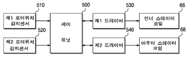
도 6을 참고하면, 본 발명에 따른 세탁기 제어장치는 인너 스테이터 코어(310)에 권선된 인너 스테이터 코일(66)로 인가되는 제1구동신호를 발생하는 제1드라이버(530)와, 아우터 스테이터 코어(312)에 권선된 아우터 스테이터 코일(68)로 인가되는 제2구동신호를 발생하는 제2드라이버(540)와, 상기 제1드라이버(530), 제2드라이버(540) 및 세탁기 전체를 제어하는 제어유닛(500)을 포함한다.6, the controller of the washing machine according to the present invention includes a
상기 제어유닛(500)은 상기와 같이 제1 및 제2 드라이버(530,540)에 대한 제어와 동시에 세탁기 전체를 제어하도록 시스템 제어부 역할을 하거나, 또는 세탁기 본체의 시스템 제어부로부터 사용자가 설정한 세탁코스에 따라 결정되는 세탁 제어신호를 수신한 후 이에 기초하여 제1 및 제2 드라이버(530,540)에 개별적인 제어신호를 인가하는 드라이버 전용의 제어장치로 구성할 수 있다. 상기 제어유닛(500)은 마이콤이나 마이크로프로세서와 같은 신호처리장치로 구성될 수 있으며, PWM(Pulse Width Modulation) 제어신호를 발생하기 위하여 PWM 제어부를 내장하거나 별도로 구비한다.The
상기한 바와 같이, 본 발명의 구동모터(140)는 더블 로터-더블 스테이터로 구성된 쌍동력 구조의 BLDC 모터로 이루어진 것이고, 예를 들어, U, V, W 3상 구동방식으로 모터 제어가 이루어진다. 따라서, 스테이터(60)의 인너 및 아우터 스테이터 코일(66,68)도 각각 U, V, W 3상 코일로 구성된다.As described above, the driving
본 발명의 스테이터(60)는 인너 로터(40)와 아우터 로터(50)를 각각 구동하도록 인너 스테이터 코일(66)을 구비하는 인너 스테이터(60a)와, 아우터 스테이터 코일(68)을 구비하는 아우터 스테이터(60b)를 포함하는 더블 스테이터를 형성한다.The
그 결과, 인너 스테이터(60a)와, 인너 스테이터(60a)에 의해 회전이 이루어지는 인너 로터(40)는 인너 모터를 형성하고, 아우터 스테이터(60b)와, 아우터 스테이터(60b)에 의해 회전이 이루어지는 아우터 로터(50)는 아우터 모터를 형성하며, 상기 인너 모터와 아우터 모터는 각각 BLDC 방식으로 제어가 이루어지도록 모터 구조가 설계되고 제1 및 제2 드라이버(530,540)에서는 예를 들어, 6-스텝 방식의 구동 제어가 이루어진다.As a result, the
상기 제1 및 제2 드라이버(530,540)는 각각 토템폴 구조로 접속된 3쌍의 스위칭 트랜지스터로 구성되는 인버터로 이루어질 수 있고, 각각의 인버터의 U, V, W 3상 출력은 인너 및 아우터 스테이터 코일(66,68)의 U, V, W 3상 코일로 인가된다.The first and
제어유닛(500)은 각각 예를 들어, 홀 센서(Hall sensor)로 이루어진 제1 및 제2 로터위치 감지센서(510,520)로부터 검출된 인너 로터(40)와 아우터 로터(50)의 회전위치에 기초하여 PWM 방식의 제어신호를 제1 및 제2 드라이버(530,540)로 인가하며, 제1 및 제2 드라이버(530,540)는 제어신호를 받아서 U, V, W 3상 출력을 인너 및 아우터 코일(66,68)의 U, V, W 3상 코일로 인가하여 인너 로터(40)와 아우터 로터(50)를 회전 구동한다.The
제어유닛(500)은 메모리장치에 각종 세탁코스를 실행하기 위한 프로그램을 보유하고 있으며, 모든 세탁코스는 기본적으로 세탁행정, 헹굼행정, 탈수행정을 포함하고 있으며, 또한 각 행정에는 급수행정과 배수행정이 전후로 포함되어 있으며, 세탁코스에 따라 세탁행정, 헹굼행정, 탈수행정 중 적어도 하나를 다수회 반복하여 수행한다.The
이와 같이, 구성되는 본 발명에 따른 세탁기의 작용을 도 7을 참고하여 다음에 설명한다. The operation of the washing machine according to the present invention thus constructed will be described below with reference to Fig.
도 7을 참조하면, 본 발명에 따른 세탁기는 먼저 단계(S200)에서 세탁기의 전원이 턴 온된다.Referring to FIG. 7, the washing machine according to the present invention is first turned on in step S200.
이와 같은 상태에서 제어유닛(500)은 사용자의 선택에 따라 입력되는 세탁 제어신호를 통해 현재 세탁 또는 헹굼 행정을 수행하는 지의 여부를 판단한다(S202).In this state, the
상기 판단 결과, 세탁 또는 헹굼 행정을 수행할 경우에 상기 제어유닛(500)은 도시되지 않은 세탁물의 무게(부하량)를 검출하고, 검출된 세탁물의 무게(부하량)에 따라 수위 단계를 설정하고 급수를 시작한다. As a result of the determination, when the laundry or rinse cycle is performed, the
또한, 세탁물의 무게(부하량)와 세탁물의 종류에 따라 사용자가 설정한 세탁코스에 따라 세탁행정단계를 설정한다. 설정된 급수가 완료되고 세탁행정단계가 설정되면 설정된 세탁행정을 시작한다.In addition, the washing and drying step is set according to the laundry course set by the user depending on the weight (load amount) of the laundry and the type of the laundry. When the set water supply is completed and the washing and drying step is set, the set washing cycle is started.
즉, 설정된 세탁 또는 헹굼 행정에 따라 제1드라이버(530) 및 제2드라이버(540)의 인버터를 구동시킨다(S204).That is, the inverter of the
그러면, 상기 제1드라이버(530) 및 제2드라이버(540)가 선택적, 독립적으로 3상 교류전력을 발생시키고, 발생시킨 3상 교류전력은 스테이터(60)의 인너 스테이터 코일(66) 및 아우터 스테이터 코일(68)에 인가됨에 따라 다양한 세탁 코스 중 어느 하나의 방법으로 구동되어 세탁이 이루어진다. 상기한 세탁 또는 헹굼 행정은 다양한 세탁 코스에 따라 다수회 반복하여 진행되며, 다양한 세탁수류를 조합하여 세탁 행정이 진행될 수 있다.The
더블 로터-더블 스테이터 방식의 구동모터(140)를 이용한 세탁방법에 대하여는 이하에 상세하게 설명한다.A washing method using the double rotor-double stator
그 후, 상기 제어유닛(500)은 모든 로터를 정지시킨 상태에서 현재 탈수 행정을 수행하는지의 여부를 판단하거나 또는 상기 단계(S202)에서 세탁 행정 또는 헹굼 행정이 아닐 경우에 탈수 행정을 수행해야되는 지의 여부를 판단한다(S208).Thereafter, the
상기 판단 결과 탈수 행정을 수행해야될 경우에 상기 제어유닛(500)은 인너 로터(40)만을 구동하거나 또는 인너 로터(40)와 아우터 로터(50)를 동일한 방향/동일한 RPM으로 회전할 수 있도록 제1드라이버(530) 및 제2드라이버(540)를 제어하여 인너 스테이터 코일(66)과 아우터 스테이터 코일(68)에 동일한 구동신호를 인가한다. 이에 따라 발생된 인너 로터(40)와 아우터 로터(50)의 회전력은 아우터 샤프트(20)와 인너 샤프트(30)를 통하여 세탁조(120)와 펄세이터(130)에 전달하여 일방향으로 동일한 속도로 회전되게 하여 탈수 행정을 수행한다(S212).The
그리고 상기 제어유닛(500)은 탈수 행정의 수행시간이 경과되었는 지의 여부를 판단하고(S214), 탈수 행정의 시간이 경과되었을 경우에 세탁물의 세탁 동작을 종료한다.Then, the
상기한 본 발명에 따른 세탁 또는 헹굼 행정을 부연설명하면, 다음과 같다.The washing or rinsing cycle according to the present invention will now be described in further detail.
세탁 또는 헹굼 행정을 수행할 경우에 상기 제어유닛(500)은 세탁 또는 헹굼 행정에 따라 제1드라이버(530) 및 제2드라이버(540)의 인버터를 구동시킨다.When performing a washing or rinsing cycle, the
그러면, 상기 제1드라이버(530) 및 제2드라이버(540)가 3상 교류전력을 발생시키고, 발생된 3상 교류전력은 스테이터(60)의 인너 스테이터 코일(66) 및 아우터 스테이터 코일(68)에 선택적, 독립적으로 인가된다. 이에 따라 스테이터(60)의 인너 스테이터 코일(66) 및 아우터 스테이터 코일(68)에 의해 구동되는 인너 로터(40) 및 아우터 로터(50)의 출력은 각각 유사한 고토크 특성을 가지는 회전력을 제공한다.The
세탁 또는 헹굼 행정을 수행할 때, 제1드라이버(530)로부터 인너 스테이터(60a)의 인너 스테이터 코일(66)로 3상 교류전력을 인가하면, 인너 로터(40)가 회전되고, 인너 로터(40)의 출력은 인너 로터(40)와 연결된 아우터 샤프트(20)로 전달된다. When the three-phase AC power is applied from the
한편, 본 발명에서는 구동모터(40)의 인너 로터(40)와 아우터 로터(50)가 양방향 회전이 가능한 제1 및 제2 베어링(26,28)과, 제1 및 제2 슬리브 베어링(80,82)에 의해 지지되어 있기 때문에 펄세이터(130) 및 세탁조(120)의 회전방향과 회전속도를 다양하게 제어할 수 있고 다양한 세탁 수류를 형성할 수 있다. In the present invention, the
특히, 펄세이터(130)와 세탁조(120)를 서로 다른 방향(반대 방향), 다른 속도, 다른 주기로 구동시킬 경우, 여러 가지 패턴의 강한 세탁 수류를 최소한의 에너지를 사용하여 형성할 수 있다. In particular, when the
본 발명에 따른 상호 반대방향 세탁 수류 형성방법은 기본적으로, 아우터 로터(50)의 구동에 의해 펄세이터(130)를 일방향, 예를 들어, 순방향, 즉 시계 방향(CW)으로 회전 구동하고, 미리 설정된 시간 동안 모터 온타임(ON TIME)을 유지한 후, 방향 전환을 위한 소정의 정지시간(OFF TIME)을 갖는다. The method of forming counter-direction washing water according to the present invention basically comprises rotating the
이 경우, 펄세이터(130)의 회전속도를 예를 들어, 160RPM의 목표 RPM까지 얼마나 빠르게 상승하는 지에 따라 이에 연동하여 회전되는 세탁물과 세탁수도 이에 연동하여 강한 회전이 이루어지게 된다. 도 9 내지 도 11과 같이 짧은 시간 내에 급상승시키면 강한 물살이 발생되어 세탁물에 큰 마찰력이 인가되게 되고, 도 12와 같이 점진적으로 회전속도를 상승시키면 세탁물에 큰 마찰력이 인가되는 것을 피할 수 있어 울(wool)과 같이 부드러운 세탁이 요구되는 경우에 적용될 수 있다. In this case, depending on how quickly the rotational speed of the
또한, 아우터 로터(50)를 목표 RPM인 160RPM으로 상승시키는 방법은 도 9와 같은 오버슈팅(overshooting) 구동, 도 10과 같은 시간에 따라 서서히 RPM을 높이는 순차적인 기동방법, 도 12의 다단계의 램프-업(ramp-up) 구동 등의 기동방법 중 하나를 적용할 수 있다. The method of raising the
본 발명에서는 펄세이터(130)가 적어도 2.5초간 회전이 이루어진 후, 방향 전환을 위한 소정의 정지시간(OFF TIME)을 갖기 위해 아우터 로터(50)를 정지시킨다.In the present invention, after the
아우터 로터(50)를 정지시키는 방법은 아우터 스테이터에 대한 구동전원을 차단하여 정지시키는 방법, 제2드라이버(540)를 이용하여 아우터 로터(50)에 대한 전자 브레이크를 실시하는 방법 중 하나를 선택할 수 있다.The method of stopping the
이 경우, 펄세이터(130)의 정지를 가능한 짧은 시간에 구현되도록 제2드라이버(540)를 이용하여 아우터 로터(50)에 대한 전자 브레이크를 실시하면, 상부의 세탁물이 밑으로 들어가는 롤링이 발생하면서 세탁물과 세제의 혼합이 이루어질 수 있으며 동시에 강한 3차원 입체 수류가 형성된다. In this case, when the electromagnetic brake is applied to the
한편, 인너 로터(40)에 의해 역방향 구동되는 세탁조(120)는 펄세이터(130)의 구동과 다른 주기로 구동이 이루어진다. 세탁조(120)는 펄세이터(130)의 구동시간, 즉 모터 온타임(ON TIME)이 종료되기 직전까지 정지된 상태를 유지하고 있다가 펄세이터(130)의 구동이 종료되기 전에 기동하여 펄세이터(130)의 회전 방향과 반대방향으로 회전 구동이 이루어진 후, 펄세이터(130)의 구동 종료 후에 짧은 기간동안 구동이 이루어진다. Meanwhile, the
이 경우, 세탁조(120)를 역방향으로 회전시키는 인너 로터(40)의 역방향 구동은 최소한으로 이루어지며, 예를 들어, (-)50RPM으로 구동이 이루어진다.In this case, the reverse rotation of the
상기와 같이, 먼저 아우터 스테이터(60b)에 의해 아우터 로터(50)를 구동하여 펄세이터(130)를 일정 기간동안 순방향(CW), 즉 시계 방향(CW)으로 구동하면 세탁조(120) 내부의 세탁물과 세탁수는 회전이 이루어짐과 동시에 원심력에 의해 세탁조(120)의 벽면을 따고 상승한 후 중앙부로 낙하하는 폭포수 형태의 흐름이 발생된다. 이러한 세탁물과 세탁수의 이동은 회전과 낙하가 이루어질 때 마찰력과 위치 에너지에 의해 세탁물과 세제의 혼합 및 세탁이 이루어지게 된다.As described above, if the
일정 기간 일정 속도로 펄세이터(130)를 회전시킨 후, 예를 들어, 아우터 스테이터에 대한 구동전원을 차단하거나 전자 브레이크를 적용하여 정지시키면 세탁물과 세탁수는 관성에 의해 짧은 시간 동안 계속 회전이 이루어지게 된다. If the
이 경우, 펄세이터(130)의 구동이 종료되기 전에 기동하여 펄세이터(130)의 구동 종료 후까지 짧은 기간 동안 인너 로터(40)의 역방향 구동이 이루어지면, 세탁조(120)도 역방향으로 회전되면서 세탁조(120)의 내벽면을 따라 역방향, 즉 반시계방향(CCW)으로 흐르는 제2수류를 발생하게 된다. 그 결과, 펄세이터(130)의 구동에 따른 순방향(CW)과 원주방향의 제1수류와 세탁조(120)의 역회전 구동에 따른 역방향(CCW)의 제2수류가 부딪치면서 큰 와류가 발생된다. In this case, if the reverse rotation of the
본 발명에서는 인너 로터(40)의 역방향 구동이 에너지 소비를 최소화하기 위해 최소한의 구동기간과 RPM으로, 예를 들어, (-)50RPM으로 약 1초 정도 구동이 이루어질지라도 펄세이터에 의한 강한 수직 상승/하강하는 제1방향의 제1수류와 세탁조에 의한 제2방향의 제2수류가 충돌하여 와류가 발생됨에 따라 에너지 소비를 최소화하면서 세정도 높은 수류를 형성할 수 있다.In the present invention, although the reverse drive of the
이와 같이 상호 반대방향 구동에 의해 발생되는 큰 와류는 세정도가 높은 강력한 3차원 입체 세탁수류를 형성한다.The large vortices generated by the reciprocal drive in this way form a strong three-dimensional three-dimensional washing water stream which is three degrees higher.
그 후, 소정의 정지시간(OFF TIME)을 가진 후 반대방향 구동을 위해 펄세이터(130)는 역방향, 즉 반시계 방향(CCW)으로 회전 구동되고, 미리 설정된 시간 동안 모터 온타임(ON TIME)을 유지한 후, 방향 전환을 위한 소정의 정지시간(OFF TIME)을 가지며, 세탁조(120)도 펄세이터(130)의 역방향 구동이 종료되기 전에 기동하여 펄세이터(130)의 구동 종료 후에 짧은 기간 동안 순방향, 즉 시계 방향(CCW)으로 회전 구동되면서, 상호 반대방향 구동에 의해 세정도가 높은 큰 와류를 발생한다.Then, the
상기한 펄세이터(130)의 시계 방향(CW) 및 반시계 방향(CCW) 구동이 완료되면 1주기가 완성되고, 2주기의 구동은 상기한 1주기와 동일하게 진행하거나 또는 다른 방식의 세탁수류 형성방법이 조합되어 진행될 수 있다.One cycle is completed when the
본 발명에서 모터 온타임(ON TIME)은, 예를 들어, 2.5초 내지 10초 범위로 설정되고, 정지시간(OFF TIME)은 0.5초 내지 2.0초 범위 내에서 설정될 수 있다. In the present invention, the motor ON time (ON TIME) may be set in the range of 2.5 seconds to 10 seconds, and the OFF time may be set in the range of 0.5 seconds to 2.0 seconds, for example.
이하에 도 8a 및 도 8b를 참고하여 본 발명에 따른 쌍동력을 이용한 상호 방향 세탁수류 형성방법에 대하여 상세하게 설명한다.Hereinafter, a method of forming a reciprocal direction washing water using a bi-directional force according to the present invention will be described in detail with reference to FIGS. 8A and 8B.
도 8a 및 도 8b를 참고하면, 먼저 제어유닛(500)은 제2드라이버(540)를 구동시켜서 3상 교류전력을 아우터 스테이터 코일(68)에 인가함에 의해 아우터 로터(50)를 순방향, 즉 시계 방향(CW)으로 회전시킴에 의해 펄세이터(130)를 순방향으로 회전시킨다(S81). 8A and 8B, the
아우터 로터(50)를 미리 설정된 RPM, 예를 들어, 160RPM으로 회전시키는 방법은 도 9와 같은 오버슈팅 구동, 도 10과 같은 시간에 따라 서서히 RPM을 높이는 순차적인 기동방법, 도 12의 다단계의 램프-업(ramp-up) 구동 등의 기동방법 중 하나를 적용할 수 있다. The method of rotating the
그 후, 미리 설정된 제1시간(T1) 동안, 즉 아우터 로터(50)(즉, 펄세이터)의 회전속도를 160RPM으로 유지한다(S82). 이와 같이 펄세이터(130)가 일방향으로 회전되면, 세탁조(120) 내부의 세탁물과 세탁수는 회전이 이루어짐과 동시에 원심력에 의해 세탁조(120)의 벽면을 따고 상승한 후 중앙부로 하강(자유낙하)하는 폭포수 형태의 이동이 이루어지면서 세탁물은 회전과 자유낙하가 반복되어 마찰력과 위치 에너지에 의한 자유낙하에 의해 세탁이 이루어지게 된다.Thereafter, the rotation speed of the outer rotor 50 (i.e., the pulsator) is maintained at 160 RPM for a predetermined first time T1 (S82). When the
만약, 미리 설정된 제1시간(T1)이 경과한 경우, 제어유닛(500)은 제1드라이버(530)를 구동시켜서 3상 교류전력을 인너 스테이터 코일(66)에 인가함에 의해 인너 로터(40)를 역방향, 즉 반시계 방향(CCW)으로 (-)50RPM으로 회전시킴에 의해 세탁조(120)를 역방향으로 회전시킨다(S83). If the predetermined first time T1 elapses, the
그 결과, 펄세이터(130)의 구동에 따른 순방향(CW)과 원주방향의 제1수류와 세탁조(120)의 구동에 따른 역방향(CCW)의 제2수류가 부딪치면서 큰 와류가 발생된다. 이와 같이 상호 반대방향 구동에 의해 발생되는 큰 와류는 세정도가 높은 강력한 3차원 입체 세탁수류를 형성한다.As a result, the first water flow in the forward direction (CW) and the second water flow in the reverse direction (CCW) due to the driving of the washing tub (120) in the circumferential direction and the second water flow in accordance with the driving of the
일반적으로, 세탁조는 많은 세탁물과 물이 채워져 있으며 펄세이터와 비교하여 중량과 부피가 크기 때문에 초기 기동시에 고토크 구동이 요구되며, 세탁조를 구동하는 인너 로터는 아우터 로터의 내측에 배치되어 있기 때문에 아우터 로터와 비교하여 구동 토크가 작게 얻어진다.In general, since the washing tub is filled with a lot of laundry and water and has a large weight and volume as compared with the pulsator, high torque driving is required at the initial stage, and since the inner rotor driving the washing tub is disposed inside the outer rotor, The drive torque is smaller than that of the rotor.
본 발명에서는 소직경의 인너 로터(40)에 대한 토크 증대를 위해 고가의 유성기어장치를 사용하는 대신에 인너 로터에 사용되는 자석을 높은 자속밀도를 갖는 희토류계 자석을 채용함에 따라 인너 로터의 구동 토크를 증대시켜서 아우터 샤프트(20)를 통하여 세탁조(120)를 무리없이 구동할 수 있다.In the present invention, instead of using an expensive planetary gear device for increasing the torque with respect to the
그 후, 펄세이터(130)의 순방향(CW) 회전이 미리 설정된 아우터 로터(50)의 턴-온 시간, 즉 아우터 로터의 온타임(ON TIME)이 경과하였는 지를 판단한다(S84). Thereafter, it is determined whether the turn-on time of the
판단결과 아우터 로터의 온타임(ON TIME)이 경과한 경우는 아우터 로터(50)를 정지시키는 단계(S85)로 진행하여 펄세이터(130)를 정지시킨다.If the ON time (ON TIME) of the outer rotor has elapsed, the flow goes to step S85 to stop the
본 발명에서는 아우터 로터(50)의 구동을 차단하여 펄세이터(130)를 정지시키는 경우에도 아우터 로터를 전자 브레이크 또는 프리휠링 상태로 설정하는 경우 아우터 로터는 관성력에 의해 소정시간 회전이 이루어지고 있고, 인너 로터(40)가 역방향 회전이 진행되는 동안 와류 발생은 계속된다. In the present invention, even when the
이와 같이 본 발명은 아우터 로터(50)의 구동을 차단하여 펄세이터(130)를 정지시키는 경우에도 인너 로터(40)에 역방향 회전을 인가하여 에너지 소모를 최소화하면서도 쌍동력 구동에 의한 상호 반대방향 구동 효과를 얻을 수 있다.As described above, even when the
그 후 인너 로터(40)의 턴-온 시간, 즉 인너 로터의 온타임(ON TIME)이 경과하였는 지를 판단한다(S86). 판단결과 인너 로터의 온타임(ON TIME)이 경과한 경우는 인너 로터(40)를 정지시키는 단계(S87)로 진행하여 세탁조(120)를 정지시킨다.Then, it is determined whether the turn-on time of the
이어서, 아우터 로터(50)의 미리 설정된 정지시간이 경과하였는 지를 판단한다(S88).Then, it is determined whether a preset stop time of the
판단결과, 미리 설정된 모터 정지시간이 경과한 경우, 펄세이터(130)를 역방향(CCW)으로 회전시키고, 세탁조(120)를 순방향(CW)으로 회전시키기 위한 절차를 상기한 단계(S81) 내지 단계(S88)와 반대로 단계(S89 내지 S97)를 진행한다.As a result of the determination, if the preset motor stop time has elapsed, the procedure for rotating the
단계(S97)에서, 미리 설정된 정지시간이 경과한 경우, 포풀림 행정이 예정되어 있는 지를 판단하고(S98), 만약 포풀림 행정이 예정되어 있는 경우는 단계(S99)로 진행하여 포풀림 행정을 진행한다. If it is determined in step S97 that the pre-set stop time has elapsed, it is determined whether or not a for-release stroke is scheduled (S98). If the for-release stroke is scheduled, the process proceeds to step S99, Go ahead.
쌍동력을 이용한 상호 반대방향 구동에 의해 세탁수류를 발생하는 경우 포 꼬임이 발생할 수 있다. 따라서, 포꼬임이 검출되거나 포꼬임이 예상되는 경우, 포풀림 행정을 진행한다. 포풀림 행정은 펄세이터(130)와 세탁조(120)를 동일방향으로 동일한 속도로 회전시킴에 의해 세탁물의 포꼬임을 풀어주게 된다.If the washing water is generated by mutual opposing driving using the bi-motive force, the twisting may occur. Therefore, when the formation is detected or the formation is predicted, the forging process is carried out. The unwinding step loosens the laundry by rotating the
상기한 세탁행정은 단계(S81 내지 S97)를 포함하는 1주기 세탁행정을 완료하고, 세탁코스에 따라 2주기의 구동은 상기한 1주기와 동일하게 진행하거나, 단동력 또는 쌍동력을 이용한 다른 방식의 세탁수류 형성방법이 조합되어 진행될 수 있다.The above-described washing cycle is completed by one cycle of washing cycle including steps S81 to S97, and the two cycle cycles of the washing cycle are the same as the one cycle described above, The washing water flow forming method of the present invention can be performed in combination.
그 후, 세탁시간이 종료되었는 지를 판단하고(S100), 세탁시간이 종료된 경우는 세탁 행정을 종료하고 후속 처리 행정으로 진행하며, 세탁시간이 종료되지 않은 경우는 단계(S81)로 진행하여 상기 절차를 반복한다.When the washing time has ended, the washing cycle is terminated and the process proceeds to the next process cycle. If the washing cycle has not been completed, the process proceeds to step S81, Repeat the procedure.
이하의 실시예에서는 도 9 내지 도 12의 펄세이터와 세탁조의 RPM 타이밍도를 참고하여 본 발명에 따른 세탁기 구동장치(150)의 쌍동력을 이용한 상호 반대방향 세탁 수류 형성방법에 대하여 설명한다. In the following embodiments, a description will be given of a method of forming mutually oppositely directed washing water using the bi-motive force of the washing
(실시예 1)(Example 1)
도 9의 상호 반대방향 세탁 수류 형성을 위한 펄세이터와 세탁조의 RPM 타이밍도를 참고하면, 본 발명의 실시예 1에 따른 상호 반대방향 세탁 수류 형성방법은 기본적으로, 펄세이터(130)를 일방향, 예를 들어, 순방향, 즉 시계 방향(CW)으로 회전 구동하고, 미리 설정된 시간동안 모터 온타임(ON TIME)을 유지한 후, 방향 전환을 위한 소정의 정지시간(OFF TIME)을 갖는다. Referring to the RPM timing diagram of the pulsator and the washing tank for forming the countercurrent washing water in the mutually opposite directions in FIG. 9, the method for forming the countercurrent washing water in the opposite direction according to the first embodiment of the present invention basically includes the step of rotating the
도 9에서 그래프(P)는 펄세이터(130)를 구동하기 위한 아우터 로터(50)의 RPM을 나타낸 것이고, 그래프(S)는 세탁조(spin basket)(120)를 구동하기 위한 인너 로터(40)의 RPM을 나타낸 것이다.9 shows the RPM of the
그 후, 펄세이터(130)는 타방향, 예를 들어, 역방향, 즉 반시계 방향(CCW)으로 회전 구동되고, 미리 설정된 시간동안 모터 온타임(ON TIME)을 유지한 후, 방향 전환을 위한 소정의 정지시간(OFF TIME)을 갖는다. Thereafter, the
상기한 펄세이터(130)의 시계 방향(CW) 및 반시계 방향(CCW) 구동이 완료되면 1주기가 완성되고, 2주기의 구동은 상기한 1주기와 동일하게 진행하거나 또는 다른 방식의 세탁수류 형성방법이 조합되어 진행될 수 있다.One cycle is completed when the
제1실시예에서는 펄세이터(130)에 대한 구동을 모터 온타임(ON TIME: Ton)을 예를 들어, 2.9초, 정지시간(OFF TIME: Toff)을 1.0초로 설정한 예이고, 세탁조(120)에 대한 구동은 약 1.2초로 설정된다.In the first embodiment, driving of the
본 발명에서 모터 온타임(ON TIME)은, 예를 들어, 2.5초 내지 10초 범위로 설정될 수 있고, 정지시간(OFF TIME)은 0.5초 내지 2.0초 범위 내에서 설정될 수 있다. In the present invention, the motor ON time (ON TIME) may be set in the range of, for example, 2.5 seconds to 10 seconds, and the OFF time may be set in the range of 0.5 seconds to 2.0 seconds.
이 경우, 세탁조(120)는 펄세이터(130)의 구동과 다른 주기로 구동이 이루어진다. 세탁조(120)는 펄세이터(130)의 구동시간, 즉 모터 온타임(ON TIME)이 종료되기 전까지 정지된 상태를 유지하고 있다가 펄세이터(130)의 회전 방향과 반대방향으로 회전 구동이 이루어진다. In this case, the
제2드라이버(540)에 의해 아우터 로터(50)가 순방향, 즉 시계 방향(CW)으로 예를 들어, 160RPM의 회전속도로 회전될 때, 인너 로터(40)는 제1드라이버(530)에 의해 전자 브레이크가 이루어짐에 따라 정지상태에 있고 이와 연결된 아우터 샤프트(20)와 세탁조(120)도 정지된 상태를 유지한다.The
이 경우, 바람직하게는 펄세이터(130)의 초기 구동을 강하게 시작하도록 오버슈팅방법을 이용하여 아우터 로터(50)를 200RPM으로 구동한 후, 감속하여 160RPM의 상태를 미리 설정된 시간동안 유지할 수 있다. In this case, it is preferable to drive the
이에 따라 펄세이터(130)가 강한 기동력으로 일방향의 회전이 이루어지면, 세탁물과 세탁수도 이에 연동하여 강한 회전이 이루어지게 된다. 본 발명의 실시예 1에서는 펄세이터(130)가 적어도 2.9초간 회전이 이루어진 후, 정지하게 되면, 세탁물과 세탁수는 관성에 의해 계속 회전이 이루어지게 된다. 즉, 펄세이터(130)의 정지를 가능한 짧은 시간에 구현되도록 제2드라이버(540)를 이용하여 아우터 로터(50)에 대한 전자 브레이크를 실시하면, 세탁조의 상부에 위치한 세탁물이 밑으로 들어가는 롤링이 발생하면서 강한 3차원 입체 수류가 형성된다. Accordingly, when the
이 경우, 필요에 따라 펄세이터(130)를 정지시키기 전에 초기 구동시와 유사하게 아우터 로터(50)를 160RPM에서 200RPM으로 오버슈팅 구동한 후 정지를 진행함에 의해, 더욱 강한 3차원 입체 수류를 형성할 수 있다.In this case, the
더욱이, 본 발명에서는 펄세이터(130)의 구동시간, 즉 모터 온타임(ON TIME)이 종료되기 약 0.7초 전에 정지된 상태에 있던 세탁조(120)를 펄세이터(130)의 회전방향과 반대방향으로 50RPM으로 구동하여 일방향으로 회전되고 있는 세탁물과 세탁수에 외주로부터 역방향의 회전력을 인가하면, 세탁물과 세탁수에 강한 와류가 발생하게 된다. 이 경우, 세탁조(120)에 대한 역방향 구동은 펄세이터(130)의 구동이 정지된 이후에 적어도 약 0.5초간 지속되면서 와류발생을 지속한다.In the present invention, the
이 경우, 상기 세탁조(120)에 대한 역방향의 회전은 인너 로터(40)를 아우터 로터(50)와 반대방향으로 구동함에 따라, 아우터 샤프트(20)를 통하여 세탁조(120)에 전달된다. In this case, the reverse rotation of the
상기 실시예 1과 같이, 본 발명에서는 세탁물과 세탁수에 대한 중심에서의 일방향의 회전은 펄세이터(130)를 사용하여 강하게 구동하고, 펄세이터의 구동 종료시점 전에 세탁조(120)를 역방향으로 구동하여 세탁물과 세탁수의 외주로부터 역방향의 물살을 유도함에 따라 강한 와류를 형성시키며, 그 결과 본 발명에서는 세탁조(120)를 최소한으로 구동하여 강한 세탁력을 갖는 3차원 세탁 수류를 형성하면서도 전력소모를 최소화하면서 세탁 효율을 높일 수 있게 된다.As in the first embodiment, in the present invention, the rotation of the washing machine in one direction at the center with respect to laundry and washing water is driven strongly using the
(실시예 2)(Example 2)
도 10을 참고하면, 실시예 2에 따른 상호 반대방향 세탁 수류 형성방법은 도 9에 도시된 실시예 1과 유사하다. Referring to FIG. 10, the method of forming the opposite direction washing water according to the second embodiment is similar to the first embodiment shown in FIG.
실시예 1에서는 모터 온타임(ON TIME)의 초기 구동시와 종료 전에 아우터 로터(50)를 160RPM에서 200RPM으로 오버슈팅 구동한 후 정지를 진행하였으나, 제2실시예에서는 오버슈팅 구동을 실시하지 않는다. 그대신, 와류 발생을 위해 세탁조(120)를 펄세이터(130)의 회전방향과 반대방향으로 구동하는 것을 모터 온타임(ON TIME)의 초기 구동시와 종료 전에 각각 약 1초 범위 이내로 실시하여 와류 발생 횟수를 1회 더 증가하도록 구동방법을 변경한 것이다. In the first embodiment, the
즉, 실시예 2에서는 아우터 로터(50)의 구동에 따라 펄세이터(130)를 순방향으로 160RPM으로 회전하면서 동시에 인너 로터(40)를 역방향으로 1.2초 동안 구동하여 세탁조(120)를 역방향으로 50RPM으로 회전시키고, 또한 실시예 1과 동일하게 아우터 로터(50)의 모터 온타임(ON TIME) 종료 전 0.7초 전에 시작하여 모터 온타임(ON TIME) 종료후 0.5초 동안까지 연장하여 인너 로터(40)를 역방향으로 1.2초 동안 구동하여 세탁조(120)를 역방향으로 50RPM으로 회전시킨다.That is, in the second embodiment, the
상기 실시예 1에서는 방향 전환을 위해 아우터 로터(50)의 구동 정지시에 160RPM에서 0.1초마다 40RPM씩 감속하여 120RPM, 80RPM, 40RPM까지 감속한 상태에서 전자 브레이크를 적용하고 있으나, 실시예 2에서는 160RPM에서 0.1초마다 60RPM 및 50RPM씩 감속하여 100RPM, 50RPM까지 감속한 상태에서 전자 브레이크를 적용하고 있다.In the first embodiment, the electromagnetic brake is applied in a state of deceleration of 120RPM, 80RPM, and 40RPM by deceleration by 40RPM every 0.1 seconds at 160RPM at the time of stopping the drive of the
실시예 1에서는 160RPM에서 0.3초에 걸쳐서 40RPM까지 감속한 상태에서 전자 브레이크를 적용하므로 정지시간(OFF TIME)을 1.0초 할당하고, 실시예 2에서는 160RPM에서 0.2초에 걸쳐서 50RPM까지 감속한 상태에서 전자 브레이크를 적용하므로 정지시간(OFF TIME)을 1.1초 할당하고 있다. 즉, 급격하게 아우터 로터(50)를 구동 정지시키는 경우는 상대적으로 정지시간(OFF TIME)을 더 길게 설정하는 것이 바람직하다.In the first embodiment, since the electronic brake is applied in a state where the speed is reduced from 160 RPM to 40 RPM over 0.3 seconds, the OFF time is allocated to 1.0 second. In the second embodiment, the speed is reduced from 160 RPM to 0.2 RPM Since the brake is applied, the stop time (OFF TIME) is assigned for 1.1 seconds. That is, it is desirable to set the OFF time relatively longer when driving the
또한, 실시예 2에 따른 상호 반대방향 세탁 수류 형성방법은 펄세이터(130)의 순방향 회전, 정지, 역방향 회전, 정지의 1주기 세탁행정이 완료된 후, 1주기 세탁행정과 동일한 세탁행정을 세탁코스에 따라 반복하여 적용할 수 있고, 다른 종류의 세탁 수류나 포풀림 행정을 조합하는 것도 가능하다.In the method of forming mutually oppositely directed washing water according to the second embodiment, after the one cycle washing cycle of the forward rotation, the stop, the reverse rotation and the stop of the
실시예 2에서는 1주기 세탁행정이 완료된 후, 제2주기 세탁행정시에 모터 온타임(ON TIME)의 펄세이터(130)의 구동 RPM을 속도를 가변하는 세탁 수류방식을 적용한 것을 나타낸 것이다. In the second embodiment, a washing water flow system in which the speed of the driving RPM of the
BLDC 모터를 사용한 구동장치에서는 로터의 RPM 가변을 쉽게 구현할 수 있어, 펄세이터(130)를 구동하기 위한 아우터 로터(50)의 회전속도를 160RPM에서 110RPM으로 낮추었다가 다시 160RPM으로 높이는 속도 조절을 적용할 수 있으며, 이에 의해 일정 간격으로 밀려오는 파도와 같은 세탁 수류를 발생할 수 있게 된다. The rotation speed of the
실시예 2에 따른 상호 반대방향 세탁 수류 형성방법에서 나머지 부분은 실시예 1과 동일하므로 이에 대한 설명은 생략한다.The remaining parts of the method for forming the opposite direction washing water according to the second embodiment are the same as those of the first embodiment, and a description thereof will be omitted.
(실시예 3)(Example 3)
도 11을 참고하면, 실시예 3에 따른 상호 반대방향 세탁 수류 형성방법은 전체적으로 실시예 1 및 실시예 2와 유사하다. Referring to FIG. 11, the method of forming the washing water in mutually opposite directions according to the third embodiment is similar to the first and second embodiments as a whole.
실시예 1 및 실시예 2와 실시예 3 사이의 차이점은 모터 온타임(ON TIME)의 초기 구동시와 종료 전에 아우터 로터(50)를 160RPM에서 200RPM으로 오버슈팅 구동하는 것 대신에 회전속도를 160RPM로 높여서 펄세이터(130)를 구동하기 위한 회전속도와 구동 토크를 높였다.The difference between the first embodiment and the second embodiment and the third embodiment is that instead of driving the
또한, 모터 온타임(ON TIME)의 중간 부분에 아우터 로터(50)의 RPM을 160RPM에서 120RPM으로 낮추었다가 높이는 속도 조절 구간(Pd)을 삽입함에 의해 큰 파도와 같은 강한 파워를 갖는 세탁 수류를 발생할 수 있다.In addition, the RPM of the
더욱이, 실시예 3에서 모터 온타임(ON TIME)은 실시예 1 및 실시예 2보다 더 짧게 설정하고 정지시간(OFF TIME)은 더 길게 설정한 것이다. 모터 온타임(ON TIME)의 펄세이터(130)의 RPM이 실시예 1 및 실시예 2보다 높은 100RPM의 회전속도에서 정지가 이루어지며, 이를 고려하여 정지시간(OFF TIME)을 1.8초로 길게 설정된다.Furthermore, the motor ON time (ON time) in the third embodiment is set shorter than that in the first and second embodiments, and the OFF time is set longer. The RPM of the
실시예 3에서 모터 온타임(ON TIME)을 2.7초, 정지시간(OFF TIME)을 1.8초, 세탁조(120)에 대한 구동은 약 1.2초로 설정된다.In the third embodiment, the ON time is set to 2.7 seconds, the OFF time is set to 1.8 seconds, and the operation to the
실시예 3에서는 160RPM에서 0.3초에 걸쳐서 100RPM까지 감속한 상태에서 전자 브레이크를 적용하여 정지상태에 도달한다. 즉, 펄세이터(130)의 RPM이 100RPM의 높은 회전속도에서 정지가 이루어지는 것을 고려하여 적어도 2단계의 경사 기울기를 가지고 감속되면서 정지상태에 도달하도록 제어가 이루어진다. In Embodiment 3, the electronic brake is applied in a state of decelerating from 160RPM to 0.3RPM over 0.3 seconds to reach the stop state. That is, considering that the
또한, 정지시간(OFF TIME)도 전자 브레이크 1.0초에 프리 휠링(Free-wheeling) 0.5초와 기동준비 0.3초를 더하여 상기 실시예 1 및 실시예 2보다 더 긴 1.8초를 할당한다. 상기 프리 휠링은 펄세이터(130)의 전자 브레이크 이후에 관성회전이 이루어지도록 모든 제어를 해제하는 것이다.In addition, the OFF time is also assigned to 1.8 second longer than the first and second embodiments by adding 0.5 seconds of free-wheeling and 0.3 seconds of startup preparation to the electronic brake 1.0 second. The freewheeling is to release all control so that an inertial rotation occurs after the electromagnetic brake of the
상기한 바와 같이, 실시예 3에서는 펄세이터(130)를 구동하는 모터 온타임(ON TIME) 시간을 짧게 설정하면서도 100RPM의 높은 회전속도에서 급 정지를 실시하고 또한 세탁조(120)를 상기한 실시예 1 및 2와 동일하게 펄세이터(130)의 구동 종료 전부터 시작하여 구동 종료후까지 역방향으로 50RPM으로 회전시킨다.As described above, according to the third embodiment, even when the motor ON time (ON time) for driving the
상기 실시예 3과 같이, 본 발명에서는 세탁물과 세탁수에 대한 중심에서의 일방향의 회전은 펄세이터(130)를 사용하여 강하게 짧게 구동한 후, 펄세이터를 급 제동하면서 펄세이터의 구동 종료시점 전에 세탁조(120)를 역방향으로 구동하여 세탁물과 세탁수의 외주로부터 역방향의 물살을 유도하면 강한 와류를 형성시킬 수 있다. 그 결과 본 발명에서는 펄세이터(130)의 구동시간을 최소한으로 진행하여 전력소모를 최소화하면서도 강한 세탁력을 갖는 3차원 세탁 수류를 형성하여 세탁 효율을 높일 수 있게 된다.As in the case of the third embodiment, in the present invention, the one-way rotation of the laundry and the washing water in the center is driven strongly by using the
(실시예 4)(Example 4)
도 12를 참고하면, 실시예 4에 따른 상호 반대방향 세탁 수류 형성방법은 전체적으로 실시예 1 내지 실시예 3과 유사하다. Referring to FIG. 12, the method of forming washing water in mutually opposite directions according to the fourth embodiment is generally similar to the first to third embodiments.
실시예 4와 실시예 1과의 차이점은 모터 온타임(ON TIME)시에 아우터 로터(50)의 초기 구동은 오버슈팅 구동하는 것 대신에 아우터 로터(50)의 회전속도를 최대 200RPM으로 높여서 펄세이터(130)를 구동하기 위한 회전속도와 구동 토크를 높인다.The difference between the fourth embodiment and the first embodiment is that the initial driving of the
또한, 모터 온타임(ON TIME)시에 펄세이터를 기동할 때 아우터 로터(50)의 RPM을 미리 설정된 200RPM까지 다단계의 램프-업(ramp-up) 방식으로 속도를 증가시키고, 회전방향의 전환을 위해 펄세이터(130)를 정지시킬 때 최단 시간에 급 제동하여 정지상태에 도달하도록 제어함에 의해 강한 수류를 형성할 수 있다.In addition, when the pulsator is started at the motor ON time (ON TIME), the RPM of the
실시예 4에서 아우터 로터(50)를 미리 설정된 RPM으로 회전시키는 방법은 상기한 램프업(ramp-up) 기동, 시간에 따라 서서히 RPM을 높이는 순차적인 기동방법 등의 주지된 기동방법 중 하나를 적용할 수 있다.The method of rotating the
실시예 4에서는 펄세이터(130)의 급 제동에 의한 정지를 고려하여 정지시간(OFF TIME)은 실시예 1 내지 3보다 더 길게 설정하는 것이 바람직하며, 이에 따라 정지시간(OFF TIME)도 전자 브레이크 1.5초와 기동준비 0.5초를 더하여 상기 실시예 1 내지 실시예 3보다 더 긴 2.0초를 할당한다. In the fourth embodiment, it is preferable that the OFF time is set to be longer than that of the first to third embodiments in consideration of stoppage of
더욱이, 실시예 4에서는 실시예 3보다도 더 높은 모터 온타임(ON TIME)의 펄세이터(130)의 RPM이 200RPM의 높은 회전속도에서 정지가 이루어지는 것을 고려하여 모터 온타임(ON TIME)을 4.5초, 정지시간(OFF TIME)을 2.0초, 세탁조(120)에 대한 구동은 1.2초로 설정된 것이다.Furthermore, in the fourth embodiment, in consideration of the fact that the RPM of the
상기 실시예 4에서는 실시예 3과 유사하게 세탁물과 세탁수에 대한 중심에서의 일방향의 회전은 펄세이터(130)를 사용하여 강하게 구동한 후, 펄세이터를 급 제동하면서 펄세이터의 구동 종료시점 전에 세탁조(120)를 역방향으로 구동하여 세탁물과 세탁수의 외주로부터 역방향의 물살을 유도하면 강한 와류를 형성시킬 수 있다. 그 결과 본 발명에서는 펄세이터(130)의 강한 급 제동과 세탁조(120)의 역방향 구동을 조합하여 강한 세탁력을 갖는 3차원 세탁 수류를 형성하여 세탁 효율을 높일 수 있게 된다.In the fourth embodiment, similarly to the third embodiment, the one-directional rotation of the laundry and the washing water with respect to the washing water is strongly driven using the
상기한 실시예 1은 운전율이 74%, 실시예 2는 73%, 실시예 3은 60%, 실시예 4는 67%이다. In Example 1, the operation ratio is 74%, Example 2 is 73%, Example 3 is 60%, and Example 4 is 67%.
수류 세탁 행정시에 모터 온타임(ON TIME)과 정지시간(OFF TIME)의 비율을 변경하여 세탁기의 운전율을 적절하게 설정하면, 소비전력 절감과 세정도의 향상을 도모할 수 있다.When the running rate of the washing machine is appropriately set by changing the ratio of the motor on time (ON time) and the stop time (OFF time) during the water flow washing, the power consumption and the degree of improvement can be improved.
본 발명에서는 소비전력을 최소화하면서 효율 상승을 위해 운전율은 적어도 60% 이상이고, 펄세이터(아우터 로터)의 RPM과 세탁조(인너 로터)의 RPM은 3:1보다 더 크게 설정되는 것이 바람직하다.In the present invention, it is desirable that the operation rate is at least 60% or more for increasing the efficiency while minimizing power consumption, and the RPM of the pulsator (outer rotor) and the RPM of the washing tank (inner rotor) are set to be larger than 3: 1.
한편, 상기 세탁 수류 형성 중 모터 구동 토크 조절과 회전유지 구간에서 펄세이터(130)를 가변 속도로 구동하면 리듬 수류를 형성할 수 있고, 에너지 소모를 절약할 수 있다. 또한 펄세이터(130)의 회전 RPM을 가변하여 강->중->약->강->중->약 등과 같이 강, 중, 약 수류를 혼용하면 보다 적은 에너지로 높은 세정도 및 헹굼도를 기대할 수 있다.Meanwhile, when the
상기 실시예 설명에서는 펄세이터와 세탁조를 구동하는 모터의 정지방법을 전자 브레이크를 이용하는 것을 예로 들었으나, 실시예 3과 같이 정지시간이 길게 소요되는 프리 휠링(Free-wheeling) 방식을 전자 브레이크와 조합하거나 프리 휠링만으로 정지하는 것도 가능하다. 또한, 모터의 정지시에 전자 브레이크 이외에 주지된 다른 방법을 사용할 수 있다.In the above embodiment, the electromagnetic brake is used as a stopping method of the motor for driving the pulsator and the washing tub. However, as in the third embodiment, the free-wheeling method requiring a long stopping time is combined with the electromagnetic brake It is also possible to stop by free wheeling. Further, other methods other than the electromagnetic brake can be used at the time of stopping the motor.
또한, 본 발명은 정역회전을 하는 사이에 펄세이터의 정지시간을 적절하게 설정함에 의해 세탁물의 꼬임을 줄여주고, 세탁물이 회전하면서 세탁조 내에서 고르게 퍼질 수 있도록 하며, 세탁물의 자세와 위치를 변경하여 세척효과를 향상시킨다.In addition, the present invention reduces the kink of the laundry by appropriately setting the stop time of the pulsator during the forward / reverse rotation, allows the laundry to spread evenly in the washing tub while rotating, and changes the posture and position of the laundry Improves cleaning effect.
또한, 본 발명에서는 펄세이터(130)의 회전 속도를 가변시킴에 의해 리듬 수류를 형성할 수 있고, 그 결과 리듬 세탁을 구현할 수 있다. 즉, 펄세이터(130)의 회전 속도가 급격하게 가변되도록 제어할 경우, 강한 수류 및 리듬 수류를 형성하면서 세탁물의 손상을 방지할 수 있다. In the present invention, the rhythm water flow can be formed by varying the rotational speed of the
세탁조(120)와 펄세이터(130)의 회전 속도 가변은 제어유닛(500)에서 제1드라이버(530) 및 제2드라이버(540)를 제어하여 인너 및 아우터 코일(66,68)로 인가되는 제1구동신호 및 제2구동신호의 전압 크기 및 전류량을 가변시킴에 의해 달성할 수 있다. The
펄세이터(130)와 세탁조(120)의 회전 속도가 완만하게 가변되도록 제어할 경우 부드러운 리듬 수류를 형성할 수 있고 세탁물의 손상을 방지한다.When the rotational speed of the
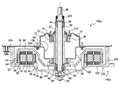
상기한 실시예 설명에서는 구동모터(140)를 채용한 제1실시예에 따른 세탁기 구동장치(150)를 이용하는 세탁기 구동방법에 대하여 설명하였으나, 본 발명은 구동모터(140a)를 채용한 제2실시예에 따른 세탁기 구동장치(150a)를 이용하는 세탁기 구동방법에 대하여도 같은 방식으로 적용될 수 있다.Although the washing machine driving method using the washing
도 13에 도시된 바와 같이, 구동모터(140a)를 채용한 제2실시예에 따른 세탁기 구동장치(150a)는 세탁조(120)와 연결되는 아우터 샤프트(20)와, 아우터 샤프트(20)의 내부에 회전 가능하게 배치되고 펄세이터(130)와 연결되는 인너 샤프트(30)와, 아우터 샤프트(20)와 연결되는 아우터 로터(50)와, 인너 샤프트(30)와 연결되는 인너 로터(40)와, 인너 로터(40)와 아우터 로터(50) 사이에 공극을 두고 배치되는 스테이터(60)를 포함한다.13, the washing
제2실시예에 따른 세탁기 구동장치(150a)는 제1실시예에 따른 세탁기 구동장치(150)와 로터의 출력 구조에서 차이가 있고, 이에 동반하여 베어링 지지구조가 변경될 수 있다.The washing
제2실시예에서 인너 로터(40), 아우터 로터(50) 및 스테이터(60)의 구동모터(140a) 구조는 제1실시예의 구동모터(140)와 동일하고, 제2베어링(28)과 제2베어링 하우징(10)도 제1실시예와 동일하다.The structure of the
아우터 샤프트(20)는 제2실시예와 같이 단일체로 구성하거나 제1실시예와 같이, 제1 및 제2 샤프트(22,24)의 결합구조로 이루어지는 것도 가능하다.The
따라서, 제1실시예와 제2실시예 사이에 동일한 부분은 동일한 부재번호를 부여하고 이에 대한 상세한 설명은 생략한다.Therefore, the same parts between the first embodiment and the second embodiment are denoted by the same reference numerals, and a detailed description thereof will be omitted.
제1실시예와 제2실시예 사이에 차이점은 제1베어링(26)이 스테이터 지지체와 분리된 제1베어링 하우징(102)에 설치된 것이다. 그러나, 제1베어링(26)은 제1실시예와 유사하게 스테이터 지지체로부터 연장되어 형성되는 제1베어링 하우징에 설치되는 것도 가능하다.The difference between the first embodiment and the second embodiment is that the
제1베어링 하우징(102)은 금속재질로 형성되고, 제1베어링(26)이 안착되는 제1베어링 안착부(104)와, 제1베어링 안착부(104)에서 외측방향으로 연장되어 상측방향으로 절곡되어 원통 형태를 이루는 연결부(106)와, 연결부(106)의 상단에서 외측방향으로 연장되어 외조(110)에 고정되는 평판부(108)를 포함한다. 평판부(108)는 볼트(250)에 의해 제2베어링 하우징(10)의 평판부(18)와 함께 외조(110)에 고정된다.The
아우터 샤프트(20)에는 아우터 로터(50)의 아우터 로터 지지체(56)가 연결되는 제1연결부(90)가 형성되고, 인너 샤프트(30)의 하측에는 인너 로터(40)의 인너 로터 지지체(46)가 연결되는 제2연결부(92)가 형성된다. A
여기에서, 제1연결부(90)는 제1베어링(26)의 하부에 배치되어 있으나, 제1베어링(26)이 스테이터 지지체로부터 연장되어 형성되는 제1베어링 하우징에 설치되는 경우, 제1연결부(90)는 제1베어링과 제2베어링 사이에 형성되어 모터의 전체 높이를 줄일 수 있다. In this case, the
즉, 제1연결부(90)가 제1베어링(26)과 제2베어링(28) 사이에 배치되면, 기존의 아우터 샤프트의 제1베어링(26) 하측에 형성되는 제1연결부의 길이만큼 아우터 샤프트의 길이를 줄일 수 있게 되고, 이에 따라 세탁기 모터의 높이를 줄일 수 있다. That is, when the first connecting
모터의 높이가 줄어들면 그 만큼 세탁기의 전체 높이를 줄일 수 있어 사용자가 세탁물을 탑 로딩할 경우 쉽고 편리하며, 전체 높이가 동일할 경우 세탁조의 사이즈를 증대시킬 수 있어 세탁기 용량을 증대시킬 수 있다.If the height of the motor is reduced, the overall height of the washing machine can be reduced by that much, so that it is easy and convenient when the user loads the laundry in the top, and when the overall height is the same, the size of the washing tub can be increased.
스테이터(60)는 방사상으로 배열되는 다수의 스테이터 코어(62)와, 스테이터 코어(62)의 외주면에 감싸지는 비자성체인 보빈(64)과, 스테이터 코어(62)의 일측에 감겨지는 인너 스테이터 코일(66)과, 스테이터 코어(62)의 타측에 감겨지는 아우터 스테이터 코일(68)과, 스테이터 코어(62)가 환형으로 배열되고 외조(110)에 고정되는 스테이터 지지체(230)를 포함한다. The
스테이터 지지체(230)는 금형에 원주방향으로 스테이터 코어(62)를 일정 간격을 두고 배열한 후 인서트 몰딩에 의해 스테이터 코어(62)와 일체로 형성된다. The
스테이터 지지체(230)는 스테이터 코어(62)와 일체로 형성되는 코어 고정부(232)와, 코어 고정부(232)의 하단에서 외측방향으로 연장된 후 직각으로 절곡되어 상측으로 연장되는 연결부(234)와, 연결부(234)의 상측에서 절곡되어 외측으로 연장되어 외조(110)에 고정되는 외조 고정부(236)를 포함한다.The
제2실시예에 따른 세탁기 구동장치(150a)에서도 인너 로터(40)는 구동토크가 아우터 로터(50)에 비해 작고, 펄세이터(130)는 세탁조(120)에 비해 작은 토크를 필요로 하므로, 인너 로터(40)는 펄세이터(130)를 충분히 회전시킬 수 있다. Since the driving torque of the
따라서, 아우터 로터(50)가 회전되면 아우터 샤프트(20)가 회전되고 아우터 샤프트(20)와 연결된 세탁조(120)가 회전된다. Accordingly, when the
아우터 로터(50)는 인너 로터(40)에 비해 큰 토크를 갖도록 설계되고, 세탁조(120)는 펄세이터(130)에 비해 큰 토크를 필요로 한다. The
제2실시예에 따른 구동모터(140a)는 큰 구동토크를 갖는 아우터 로터(50)가 큰 토크를 필요로 하는 세탁조(120)와 연결되고, 아우터 로터(50)에 비해 상대적으로 작은 토크를 갖는 인너 로터(40)가 세탁조에 비해 상대적으로 작은 토크를 필요로 하는 펄세이터(130)와 연결되므로 세탁기의 성능을 향상시킬 수 있고, 전류 소비량을 줄일 수 있다. The driving
더욱이, 본 발명에서는 인너 로터(40)의 구동 토크를 증대시키도록 Nd 자석과 같은 희토류계의 고자력 자석을 사용하여 저가의 페라이트 자석을 사용하는 아우터 로터과 구동 토크를 동등하게 구현할 수 있다. 그 결과 본 발명에서는 실시예 1 내지 4와 같이 쌍동력을 이용하여 세탁 행정 및 행굼 행정시에 펄세이터와 세탁조를 동시에 구동하여 다양한 세탁 수류 및 헹굼 패턴을 형성할 수 있다. Further, in the present invention, a rare earth-base high magnetic force magnet such as Nd magnet is used to increase the driving torque of the
상기한 실시예 설명에서는 한쌍의 출력을 발생하는 쌍동력원으로, 레이디얼 갭형의 더블 로터-더블 스테이터 구조의 BLDC 모터를 구동모터로 사용하고 있으나, 액시얼 갭형 더블 로터-더블 스테이터 구조의 BLDC 모터를 구동모터로 사용할 수 있으며, 한쌍의 출력을 발생하는 동력원이라면 다른 구조, 다른 방식의 어떤 구동모터도 사용할 수 있다. In the above description of the embodiment, a BLDC motor of a double-rotor-double stator structure of a radial gap type is used as a driving power source for generating a pair of outputs. However, a BLDC motor of an axial gap double rotor- It can be used as a driving motor, and any driving motor of a different structure or other type can be used as the power source for generating a pair of outputs.
이상에서는 본 발명을 특정의 바람직한 실시예를 예를 들어 도시하고 설명하였으나, 본 발명은 상기한 실시예에 한정되지 아니하며 본 발명의 정신을 벗어나지 않는 범위 내에서 당해 발명이 속하는 기술분야에서 통상의 지식을 가진 자에 의해 다양한 변경과 수정이 가능할 것이다. While the present invention has been particularly shown and described with reference to exemplary embodiments thereof, it is clearly understood that the same is by way of illustration and example only and is not to be construed as limited to the embodiments set forth herein. Various changes and modifications may be made by those skilled in the art.
본 발명은 인너 로터와 아우터 로터의 구동 토크를 유사하게 구현한 쌍동력 구동모터를 이용하여, 고가의 토크변환장치를 사용하지 않으면서도 상호 반대방향 세탁수류를 포함한 다양한 세탁 수류를 무리없이 형성할 수 있는 세탁기 구동장치 및 그의 제어, 특히 전자동 세탁기에 적용될 수 있다.It is possible to form a variety of washing water including the washing water in mutually opposite directions without using an expensive torque converter by using a twin driving force motor in which the driving torques of the inner rotor and the outer rotor are similar to each other The present invention can be applied to a washing machine driving apparatus and its control, particularly a fully automatic washing machine.
10: 제2베어링 하우징
12: 베어링 안착부
14: 시일 고정부
16,234: 연결부
18: 평판부
20: 아우터 샤프트
22: 제1샤프트
24: 제2샤프트
26; 제1베어링
28: 제2베어링
30: 인너 샤프트
34: 제1고정너트
36; 제2고정너트
40: 인너 로터
42: 제1자석
44; 제1백요크
46: 인너 로터 지지체
48,58: 부싱
50: 아우터 로터
51,51a,53a-53c: 보강리브
52: 제2자석
54: 제2백요크10: second bearing housing 12: bearing seat
14: seal seal 16,234: connection
18: flat plate portion 20: outer shaft
22: first shaft 24: second shaft
26; First bearing 28: Second bearing
30: Inner shaft 34: First fixing nut
36; Second fixing nut 40: Inner rotor
42:
46: Inner rotor support 48, 58: Bushing
50:
52: second magnet 54: second back yoke
Claims (15)
상기 아우터 로터 출력을 펄세이터에 전달하는 인너 샤프트;
상기 인너 샤프트의 외주에 회전 가능하게 결합되며, 상기 인너 로터 출력을 세탁조에 전달하는 아우터 샤프트; 및
상기 더블 스테이터에 제1 및 제2 구동신호를 독립적으로 인가하여 인너 로터와 아우터 로터를 제어하는 제어유닛을 포함하며,
상기 제어유닛은 세탁 행정시에 상기 펄세이터가 시계방향 및 반시계방향으로 회전방향을 전환할 때 정지시간을 가지며, 상기 세탁조는 펄세이터의 시계방향 및 반시계방향의 구동시간이 종료되기 전에 기동하여 펄세이터의 회전 방향과 반대방향으로 구동이 이루어지도록 제어하는 것을 특징으로 하는 세탁기 구동장치. A double rotor-double stator type driving motor having an inner rotor and an outer rotor independently controllable by a double stator and selectively generating an inner rotor output and an outer rotor output;
An inner shaft for transmitting the outer rotor output to the pulsator;
An outer shaft rotatably coupled to an outer periphery of the inner shaft and transmitting the output of the inner rotor to a washing tub; And
And a control unit for independently controlling the inner rotor and the outer rotor by applying the first and second driving signals independently to the double stator,
Wherein the control unit has a stop time when the pulsator switches the rotation direction in the clockwise direction and the counterclockwise direction in the washing cycle, and the washing tub is operated before the pulsator's clockwise and counterclockwise driving time ends So that driving is performed in a direction opposite to the rotational direction of the pulsator.
상기 세탁조의 구동은 펄세이터의 정지시간 이후까지 연장되어 구동되는 것을 특징으로 하는 세탁기 구동장치. The method according to claim 1,
Wherein the driving of the washing tub is extended after the stop time of the pulsator.
상기 세탁조는 펄세이터의 시계방향 및 반시계방향의 기동과 동시에 펄세이터의 회전 방향과 반대방향으로 구동된 후, 펄세이터의 구동시간보다 짧게 구동이 이루어지는 것을 특징으로 하는 세탁기 구동장치. The method according to claim 1,
Wherein the washing tub is driven in a direction opposite to a rotating direction of the pulsator simultaneously with the clockwise and counterclockwise starting of the pulsator, and then the driving is performed shorter than the pulsator driving time.
상기 펄세이터의 구동시간과 정지시간은 1.5:1 내지 10:1 범위로 설정되는 것을 특징으로 하는 세탁기 구동장치. The method according to claim 1,
Wherein the driving time and the stopping time of the pulsator are set in the range of 1.5: 1 to 10: 1.
상기 펄세이터의 기동 및 정지 동작시에 오버슈팅 구동이 이루어지는 것을 특징으로 하는 세탁기 구동장치. The method according to claim 1,
Wherein the overshooting driving is performed during starting and stopping operations of the pulsator.
상기 펄세이터의 기동시에 램프-업 구동이 이루어지는 것을 특징으로 하는 세탁기 구동장치.The method according to claim 1,
And the ramp-up driving is performed at the start of the pulsator.
상기 펄세이터는 가변속도로 구동되는 것을 특징으로 하는 세탁기 구동장치.The method according to claim 1,
Wherein the pulsator is driven at a variable speed.
상기 펄세이터의 정지는 아우터 로터를 구동하는 드라이버를 이용하여 전자 브레이크를 실시하는 것을 특징으로 하는 세탁기 구동장치. The method according to claim 1,
Wherein the pulsator stops the electromagnetic brake by using a driver for driving the outer rotor.
상기 인너 로터의 구동 토크는 아우터 로터의 구동 토크와 동등하게 설정하는 것을 특징으로 하는 세탁기 구동장치. The method according to claim 1,
Wherein the driving torque of the inner rotor is set to be equal to the driving torque of the outer rotor.
상기 인너 로터는 희토류계 자석을 사용하고, 상기 아우터 로터는 페라이트 자석을 사용하는 것을 특징으로 하는 세탁기 구동장치. 10. The method of claim 9,
Wherein the inner rotor uses a rare earth magnet, and the outer rotor uses a ferrite magnet.
상기 아우터 로터는
상기 스테이터의 외면에 일정 갭을 두고 배치되며 N극 및 S극이 교대로 배치되는 다수의 제2자석;
상기 제2자석의 배면에 배치되는 제2백요크; 및
상기 제2자석 및 제2백요크를 지지하는 아우터 로터 지지체를 포함하며,
상기 아우터 로터 지지체는
컵 형상의 바닥면 중에 상기 스테이터의 인너 및 아우터 스테이터 코일과 대향한 외측평탄부와,
인너 샤프트와 결합이 이루어지는 내측평탄부와,
상기 외측평탄부와 내측평탄부를 연결하는 경사연결부를 포함하고,
상기 외측 평탄부에는 상기 인너 및 아우터 스테이터 코일과 대향한 부분에 각각 인너 및 아우터 스테이터 코일로부터 발생된 열을 외부로 배출하는 제1 및 제2 관통구멍을 구비하는 것을 특징으로 하는 세탁기 구동장치.The method according to claim 1,
The outer rotor
A plurality of second magnets arranged on the outer surface of the stator with a predetermined gap therebetween and having N poles and S poles alternately arranged;
A second back yoke disposed on a back surface of the second magnet; And
And an outer rotor support for supporting the second magnet and the second back yoke,
The outer rotor support
An outer flat portion facing the inner and outer stator coils of the stator in the cup-shaped bottom surface,
An inner flat portion engaged with the inner shaft,
And an inclined connection portion connecting the outer flat portion and the inner flat portion,
Wherein the outer flat portion includes first and second through holes for discharging the heat generated from the inner and outer stator coils to the outside, respectively, at portions facing the inner and outer stator coils.
상기 아우터 로터 지지체는
그의 외주면 및 내주면에 각각 일정한 각도마다 방사방향으로 돌출되어 있는 복수의 방사방향 보강리브; 및
그의 내주면에 원주방향으로 간격을 두고 형성되어 있는 제1 내지 제3 원주방향 보강리브를 포함하는 것을 특징으로 하는 세탁기 구동장치.13. The method of claim 12,
The outer rotor support
A plurality of radial direction reinforcing ribs protruding radially from the outer circumferential surface and the inner circumferential surface at predetermined angles, respectively; And
And the first to third circumferential direction reinforcing ribs are formed on the inner circumferential surface of the washer at intervals in the circumferential direction.
상기 인너 로터 출력을 펄세이터에 전달하는 인너 샤프트;
상기 인너 샤프트의 외주에 회전 가능하게 결합되며, 상기 아우터 로터 출력을 세탁조에 전달하는 아우터 샤프트; 및
상기 더블 스테이터에 제1 및 제2 구동신호를 독립적으로 인가하여 인너 로터와 아우터 로터를 제어하는 제어유닛을 포함하며,
상기 제어유닛은 세탁 행정시에 상기 펄세이터가 시계방향 및 반시계방향으로 회전방향을 전환할 때 정지시간을 가지며, 상기 세탁조는 펄세이터의 시계방향 및 반시계방향의 구동시간이 종료되기 전에 기동하여 펄세이터의 회전 방향과 반대방향으로 구동이 이루어지도록 제어하는 것을 특징으로 하는 세탁기 구동장치. A double rotor-double stator type driving motor having an inner rotor and an outer rotor independently controllable by a double stator and selectively generating an inner rotor output and an outer rotor output;
An inner shaft for transmitting the inner rotor output to the pulsator;
An outer shaft rotatably coupled to the outer periphery of the inner shaft and transmitting the outer rotor output to the washing tub; And
And a control unit for independently controlling the inner rotor and the outer rotor by applying the first and second driving signals independently to the double stator,
Wherein the control unit has a stop time when the pulsator switches the rotation direction in the clockwise direction and the counterclockwise direction in the washing cycle, and the washing tub is operated before the pulsator's clockwise and counterclockwise driving time ends So that driving is performed in a direction opposite to the rotational direction of the pulsator.
상기 외조의 내부에 회전 가능하게 배치되어 세탁과 탈수가 이루어지는 세탁조;
상기 세탁조 내부에 회전 가능하게 배치되어 세탁 수류를 형성하는 펄세이터; 및
상기 세탁조와 펄세이터를 동시에 또는 선택적으로 구동시키는 청구항 1 내지 청구항 13 중 어느 한 항에 따른 세탁기 구동장치를 포함하는 세탁기. An outer tub for accommodating washing water;
A washing tub which is rotatably disposed inside the outer tub to perform washing and dehydrating;
A pulsator arranged rotatably in the washing tub to form wash water; And
The washing machine according to any one of claims 1 to 13, which simultaneously or selectively drives the washing tub and pulsator.
상기 제1기간이 종료되기 전에 세탁조를 제2기간 동안 상기 제1방향과 반대방향으로 회전 구동하는 제2단계;
상기 제1기간의 경과에 따라 펄세이터를 정지시키는 제3단계;
상기 제1기간의 경과 이후에 상기 제2기간의 경과에 따라 상기 세탁조를 정지시키는 제4단계; 및
상기 제2기간의 경과 이후에 펄세이터의 정지시간이 경과하는 경우, 상기 제1 내지 제4 단계에서 펄세이터와 세탁조의 회전방향을 각각 반대로 설정하여 순차적으로 실행하는 제5단계;를 포함하는 것을 특징으로 하는 세탁기 구동방법.A first step of rotationally driving the pulsator in a first direction during a first period;
Rotating the washing tub in a direction opposite to the first direction for a second period before the first period ends;
A third step of stopping the pulsator according to the elapse of the first period;
A fourth step of stopping the washing tub according to the passage of the second period after the lapse of the first period; And
And a fifth step of, when the stop time of the pulsator has elapsed after the elapse of the second period of time, executing the rotation steps of the pulsator and the washing tub in the first to fourth steps, respectively, Wherein the washing machine is a washing machine.
Priority Applications (3)
| Application Number | Priority Date | Filing Date | Title |
|---|---|---|---|
| KR1020160062299A KR101939204B1 (en) | 2016-05-20 | 2016-05-20 | Apparatus for Driving Washing Machine, Washing Machine Using the Same and Driving Method of Washing Machine |
| PCT/KR2017/005197 WO2017200329A1 (en) | 2016-05-20 | 2017-05-19 | Washing machine driving device, washing machine having same, and washing machine driving method |
| CN201780025443.8A CN109072530B (en) | 2016-05-20 | 2017-05-19 | Washing machine driving device, washing machine with same and washing machine driving method |
Applications Claiming Priority (1)
| Application Number | Priority Date | Filing Date | Title |
|---|---|---|---|
| KR1020160062299A KR101939204B1 (en) | 2016-05-20 | 2016-05-20 | Apparatus for Driving Washing Machine, Washing Machine Using the Same and Driving Method of Washing Machine |
Publications (2)
| Publication Number | Publication Date |
|---|---|
| KR20170131092A true KR20170131092A (en) | 2017-11-29 |
| KR101939204B1 KR101939204B1 (en) | 2019-01-16 |
Family
ID=60325870
Family Applications (1)
| Application Number | Title | Priority Date | Filing Date |
|---|---|---|---|
| KR1020160062299A KR101939204B1 (en) | 2016-05-20 | 2016-05-20 | Apparatus for Driving Washing Machine, Washing Machine Using the Same and Driving Method of Washing Machine |
Country Status (3)
| Country | Link |
|---|---|
| KR (1) | KR101939204B1 (en) |
| CN (1) | CN109072530B (en) |
| WO (1) | WO2017200329A1 (en) |
Families Citing this family (2)
| Publication number | Priority date | Publication date | Assignee | Title |
|---|---|---|---|---|
| KR20190063197A (en) * | 2017-11-29 | 2019-06-07 | 엘지전자 주식회사 | Washing machine |
| KR20230055049A (en) * | 2021-10-18 | 2023-04-25 | 삼성전자주식회사 | Washing machine and controlling method for the same |
Citations (2)
| Publication number | Priority date | Publication date | Assignee | Title |
|---|---|---|---|---|
| KR19990076570A (en) | 1998-03-31 | 1999-10-15 | 니시무로 타이죠 | Dehydrating combined use washing machine |
| KR20150008347A (en) | 2013-07-12 | 2015-01-22 | 주식회사 아모텍 | Apparatus for Driving Washing Machine, Washing Machine Using the Same and Controlling Method thereof |
Family Cites Families (5)
| Publication number | Priority date | Publication date | Assignee | Title |
|---|---|---|---|---|
| KR20030090086A (en) * | 2002-05-21 | 2003-11-28 | 삼성전자주식회사 | Rinsing control method of washing machine |
| KR101228043B1 (en) * | 2011-06-08 | 2013-01-30 | 주식회사 아모텍 | Driving apparatus for direct drive type washing machine |
| KR101345326B1 (en) * | 2011-12-26 | 2013-12-30 | 주식회사 아모텍 | Motor drive circuit for washing machine and control method thereof |
| KR101601167B1 (en) * | 2013-10-10 | 2016-03-10 | 주식회사 아모텍 | Driving Apparatus for Washing Machine, Washing Machine Using the Same and Driving Method thereof |
| WO2017014588A1 (en) * | 2015-07-22 | 2017-01-26 | 주식회사 아모텍 | Apparatus for driving washing machine, washing machine having same, and method for driving washing machine |
-
2016
- 2016-05-20 KR KR1020160062299A patent/KR101939204B1/en active IP Right Grant
-
2017
- 2017-05-19 CN CN201780025443.8A patent/CN109072530B/en active Active
- 2017-05-19 WO PCT/KR2017/005197 patent/WO2017200329A1/en active Application Filing
Patent Citations (2)
| Publication number | Priority date | Publication date | Assignee | Title |
|---|---|---|---|---|
| KR19990076570A (en) | 1998-03-31 | 1999-10-15 | 니시무로 타이죠 | Dehydrating combined use washing machine |
| KR20150008347A (en) | 2013-07-12 | 2015-01-22 | 주식회사 아모텍 | Apparatus for Driving Washing Machine, Washing Machine Using the Same and Controlling Method thereof |
Also Published As
| Publication number | Publication date |
|---|---|
| WO2017200329A1 (en) | 2017-11-23 |
| CN109072530B (en) | 2021-03-12 |
| CN109072530A (en) | 2018-12-21 |
| KR101939204B1 (en) | 2019-01-16 |
Similar Documents
| Publication | Publication Date | Title |
|---|---|---|
| KR101639021B1 (en) | Apparatus for Driving Washing Machine and Washing Machine Using the Same | |
| US11525204B2 (en) | Washing machine driving device, and washing machine and driving method using same | |
| JP3524376B2 (en) | Dehydration combined washing machine | |
| CN105579636B (en) | Motor's for washing machine and washing machine with it | |
| KR101196992B1 (en) | Washing machine | |
| KR20060020265A (en) | Driving apparatus of washing machine and the controlling method of the apparats | |
| CN107636223B (en) | Washing machine driving device and washing machine with same | |
| KR102405269B1 (en) | washing machine | |
| CN107002338B (en) | Washing machine and washing machine driving method | |
| EP3733951A1 (en) | Double-rotor washing type drum washing machine | |
| KR101746067B1 (en) | Apparatus for Driving Washing Machine, Washing Machine Using the Same and Driving Method of Washing Machine | |
| KR101939204B1 (en) | Apparatus for Driving Washing Machine, Washing Machine Using the Same and Driving Method of Washing Machine | |
| KR101639023B1 (en) | Rdum driving apparatus, drum washing machine having the same and driving method thereof | |
| KR101619228B1 (en) | Washing machine and driving method thereof | |
| KR101639022B1 (en) | Rdum driving apparatus, drum washing machine having the same and driving method thereof | |
| JPH10295983A (en) | Braking method of washing machine and device therefor | |
| KR20060104416A (en) | Motor and dishwasher using the same | |
| JP2019110725A (en) | motor | |
| JP2010196554A (en) | Pump using claw pole type motor as driving source and pump drive equipment | |
| KR100504491B1 (en) | coil winding method of induction motor for washing machine and method for controlling the same | |
| JP2000237492A (en) | Washing machine | |
| KR19980034973A (en) | washer | |
| JP2002035467A (en) | Electric washing machine |
Legal Events
| Date | Code | Title | Description |
|---|---|---|---|
| A201 | Request for examination | ||
| E902 | Notification of reason for refusal | ||
| E701 | Decision to grant or registration of patent right | ||
| GRNT | Written decision to grant |