KR20170130727A - System and method for measuring position - Google Patents
System and method for measuring position Download PDFInfo
- Publication number
- KR20170130727A KR20170130727A KR1020160061279A KR20160061279A KR20170130727A KR 20170130727 A KR20170130727 A KR 20170130727A KR 1020160061279 A KR1020160061279 A KR 1020160061279A KR 20160061279 A KR20160061279 A KR 20160061279A KR 20170130727 A KR20170130727 A KR 20170130727A
- Authority
- KR
- South Korea
- Prior art keywords
- signal
- mobile device
- distance
- receiving
- server
- Prior art date
Links
Images


Classifications
-
- H—ELECTRICITY
- H04—ELECTRIC COMMUNICATION TECHNIQUE
- H04L—TRANSMISSION OF DIGITAL INFORMATION, e.g. TELEGRAPHIC COMMUNICATION
- H04L67/00—Network arrangements or protocols for supporting network services or applications
- H04L67/50—Network services
- H04L67/52—Network services specially adapted for the location of the user terminal
-
- H—ELECTRICITY
- H04—ELECTRIC COMMUNICATION TECHNIQUE
- H04W—WIRELESS COMMUNICATION NETWORKS
- H04W64/00—Locating users or terminals or network equipment for network management purposes, e.g. mobility management
-
- H—ELECTRICITY
- H04—ELECTRIC COMMUNICATION TECHNIQUE
- H04W—WIRELESS COMMUNICATION NETWORKS
- H04W64/00—Locating users or terminals or network equipment for network management purposes, e.g. mobility management
- H04W64/006—Locating users or terminals or network equipment for network management purposes, e.g. mobility management with additional information processing, e.g. for direction or speed determination
-
- G—PHYSICS
- G01—MEASURING; TESTING
- G01S—RADIO DIRECTION-FINDING; RADIO NAVIGATION; DETERMINING DISTANCE OR VELOCITY BY USE OF RADIO WAVES; LOCATING OR PRESENCE-DETECTING BY USE OF THE REFLECTION OR RERADIATION OF RADIO WAVES; ANALOGOUS ARRANGEMENTS USING OTHER WAVES
- G01S11/00—Systems for determining distance or velocity not using reflection or reradiation
- G01S11/02—Systems for determining distance or velocity not using reflection or reradiation using radio waves
- G01S11/06—Systems for determining distance or velocity not using reflection or reradiation using radio waves using intensity measurements
-
- G—PHYSICS
- G01—MEASURING; TESTING
- G01S—RADIO DIRECTION-FINDING; RADIO NAVIGATION; DETERMINING DISTANCE OR VELOCITY BY USE OF RADIO WAVES; LOCATING OR PRESENCE-DETECTING BY USE OF THE REFLECTION OR RERADIATION OF RADIO WAVES; ANALOGOUS ARRANGEMENTS USING OTHER WAVES
- G01S5/00—Position-fixing by co-ordinating two or more direction or position line determinations; Position-fixing by co-ordinating two or more distance determinations
- G01S5/0009—Transmission of position information to remote stations
- G01S5/0018—Transmission from mobile station to base station
-
- G—PHYSICS
- G01—MEASURING; TESTING
- G01S—RADIO DIRECTION-FINDING; RADIO NAVIGATION; DETERMINING DISTANCE OR VELOCITY BY USE OF RADIO WAVES; LOCATING OR PRESENCE-DETECTING BY USE OF THE REFLECTION OR RERADIATION OF RADIO WAVES; ANALOGOUS ARRANGEMENTS USING OTHER WAVES
- G01S5/00—Position-fixing by co-ordinating two or more direction or position line determinations; Position-fixing by co-ordinating two or more distance determinations
- G01S5/02—Position-fixing by co-ordinating two or more direction or position line determinations; Position-fixing by co-ordinating two or more distance determinations using radio waves
- G01S5/0269—Inferred or constrained positioning, e.g. employing knowledge of the physical or electromagnetic environment, state of motion or other contextual information to infer or constrain a position
-
- G—PHYSICS
- G01—MEASURING; TESTING
- G01S—RADIO DIRECTION-FINDING; RADIO NAVIGATION; DETERMINING DISTANCE OR VELOCITY BY USE OF RADIO WAVES; LOCATING OR PRESENCE-DETECTING BY USE OF THE REFLECTION OR RERADIATION OF RADIO WAVES; ANALOGOUS ARRANGEMENTS USING OTHER WAVES
- G01S5/00—Position-fixing by co-ordinating two or more direction or position line determinations; Position-fixing by co-ordinating two or more distance determinations
- G01S5/02—Position-fixing by co-ordinating two or more direction or position line determinations; Position-fixing by co-ordinating two or more distance determinations using radio waves
- G01S5/14—Determining absolute distances from a plurality of spaced points of known location
-
- H—ELECTRICITY
- H04—ELECTRIC COMMUNICATION TECHNIQUE
- H04W—WIRELESS COMMUNICATION NETWORKS
- H04W24/00—Supervisory, monitoring or testing arrangements
- H04W24/08—Testing, supervising or monitoring using real traffic
-
- H—ELECTRICITY
- H04—ELECTRIC COMMUNICATION TECHNIQUE
- H04W—WIRELESS COMMUNICATION NETWORKS
- H04W4/00—Services specially adapted for wireless communication networks; Facilities therefor
- H04W4/02—Services making use of location information
- H04W4/023—Services making use of location information using mutual or relative location information between multiple location based services [LBS] targets or of distance thresholds
-
- H04W4/028—
-
- H—ELECTRICITY
- H04—ELECTRIC COMMUNICATION TECHNIQUE
- H04W—WIRELESS COMMUNICATION NETWORKS
- H04W4/00—Services specially adapted for wireless communication networks; Facilities therefor
- H04W4/02—Services making use of location information
- H04W4/029—Location-based management or tracking services
-
- G—PHYSICS
- G01—MEASURING; TESTING
- G01S—RADIO DIRECTION-FINDING; RADIO NAVIGATION; DETERMINING DISTANCE OR VELOCITY BY USE OF RADIO WAVES; LOCATING OR PRESENCE-DETECTING BY USE OF THE REFLECTION OR RERADIATION OF RADIO WAVES; ANALOGOUS ARRANGEMENTS USING OTHER WAVES
- G01S2205/00—Position-fixing by co-ordinating two or more direction or position line determinations; Position-fixing by co-ordinating two or more distance determinations
- G01S2205/001—Transmission of position information to remote stations
- G01S2205/008—Transmission of position information to remote stations using a mobile telephone network
Abstract
Description
본 발명의 실시예들은 실내 측위 기술과 관련된다.Embodiments of the invention relate to indoor positioning techniques.
스마트폰을 중심으로 한 휴대용 개인 단말의 보급과 더불어, 사용자의 위치에 따라 서비스를 제공하는 위치기반서비스(LBS : Location-Based Service) 시장 또한 급속도로 성장하고 있다. 초기의 LBS는 GPS(Global Positioning System)와 같은 위성항법시스템을 통해 사용자의 위치 정보를 획득할 수 있는 실외 공간으로 그 서비스 범위가 한정되었으나, 현재는 서비스 가용 범위가 실내 공간으로까지 확대되고 있으며, 그 수요 또한 지속적으로 증가하고 있다.Along with the spread of portable personal terminals centering on smart phones, a location-based service (LBS) market that provides services according to user's location is also rapidly growing. The initial LBS is an outdoor space that can acquire user's location information through a satellite navigation system such as GPS (Global Positioning System), and its service range is limited. Currently, the service available range extends to an indoor space, The demand is also steadily increasing.
실내 측위 방식은 여러 가지가 있으나, 일반적으로 삼변 측위(Trilateration), 삼각 측위(Triangulation), 또는 핑거프린트(Fingerprint) 측위 방식이 사용된다. There are various indoor positioning methods, but in general, trilateration, triangulation, or fingerprint positioning methods are used.
그러나, 종래 측위 방식에 따르면, 다수의 RF(Radio Frequency) 수신기가 필요하게 되며 번거로운 측위 과정이 수반된다. 구체적으로, 삼변 측위 방식의 경우 최소 3개의 RF 수신기와 모바일 기기 사이의 거리가 각각 계산되어야 하며, 삼각 측위 방식의 경우 최소 3개의 RF 수신기 및 RF 수신기에서의 신호 수신 각도(또는 방향) 측정을 위한 별도의 장치가 필요하게 된다. 또한, 핑거프린트 측위 방식의 경우 다수의 RF 수신기가 필요할 뿐 아니라 각 위치에서의 핑거프린트를 사전에 미리 수집하여야 하는 번거로움이 있다. 나아가, 종래 측위 방식에 따르면, RF 수신기가 무지향성 안테나를 사용하여 신호를 감지하게 되므로, 모바일 기기의 위치 측정시 전파의 특성 및 주변 환경에 많은 영향을 받게 되며 신호가 중복되어 감지되는 위험이 발생하게 된다.However, according to the conventional positioning method, a large number of RF (Radio Frequency) receivers are required and a troublesome positioning process is involved. Specifically, in the case of the trilateral positioning method, distances between a minimum of three RF receivers and a mobile device should be calculated, respectively. In the case of the triangular positioning method, at least three RF receivers and RF receivers A separate device is required. In addition, in the case of the fingerprint positioning method, not only a plurality of RF receivers are required but also there is a need to collect fingerprints at each position in advance. Further, according to the conventional positioning method, since the RF receiver senses a signal using the omnidirectional antenna, the position of the mobile device is greatly affected by the characteristics of the radio wave and the surrounding environment, .
본 발명의 실시예들은 보다 저렴하고 간편한 방법으로 모바일 기기의 위치를 용이하게 측정하고 각 경로별 혼잡도, 모바일 기기의 동선 및 체류 시간을 제공하기 위한 것이다.Embodiments of the present invention are intended to easily measure the location of a mobile device in a more inexpensive and easy way and to provide traffic congestion and route and residence time for each route.
본 발명의 예시적인 실시예에 따르면, 지향성 안테나를 구비하며, 상기 지향성 안테나의 신호 감지 방향 측 경로에 위치한 하나 이상의 모바일 기기 각각으로부터 신호를 수신하는 수신 장치; 및 상기 신호에 관한 정보를 상기 수신 장치로부터 수신하고, 상기 신호에 관한 정보를 기반으로 상기 모바일 기기의 위치를 결정하며, 상기 위치를 이용하여 상기 경로의 혼잡도를 획득하는 서버를 포함하는, 위치 측정 시스템이 제공된다. According to an exemplary embodiment of the present invention, there is provided an apparatus comprising: a receiving device having a directional antenna, the receiving device receiving signals from each of one or more mobile devices located in a signal-sensing direction-side path of the directional antenna; And a server for receiving information about the signal from the receiving device, determining a location of the mobile device based on information about the signal, and using the location to obtain a congestion of the path, System is provided.
상기 신호에 관한 정보는, 상기 모바일 기기의 식별 정보, 상기 신호의 세기(RSSI : Received Signal Strength Indication), 상기 수신 장치의 식별 정보 및 상기 수신 장치에서 상기 신호를 수신한 시각 중 하나 이상을 포함할 수 있다. The information about the signal includes at least one of identification information of the mobile device, received signal strength indication (RSSI), identification information of the receiving device, and time at which the signal was received at the receiving device .
상기 서버는, 상기 신호에 관한 정보를 이용하여 상기 모바일 기기 및 상기 수신 장치 사이의 거리를 계산하고, 상기 거리를 이용하여 상기 모바일 기기의 위치를 결정할 수 있다. The server may calculate the distance between the mobile device and the receiving device using the information about the signal, and determine the position of the mobile device using the distance.
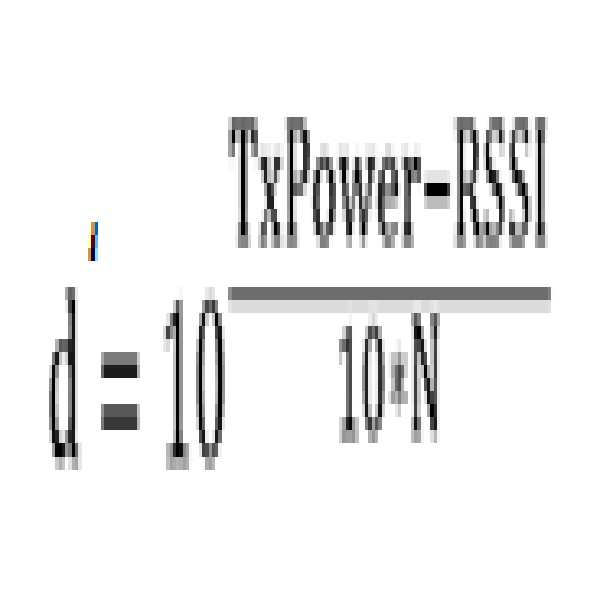
상기 서버는, 상기 경로에 위치한 테스트 기기의 위치를 변경됨에 따라 아래의 수학식 1을 이용하여 상기 테스트 기기 및 상기 수신 장치 사이의 거리를 각각 계산하고, 계산된 상기 테스트 기기 및 상기 수신 장치 사이의 거리와 상기 테스트 기기 및 상기 수신 장치 사이의 실제 거리의 차의 합이 최소가 되는 손실 신호 계수(N)을 산출할 수 있다. The server calculates a distance between the test apparatus and the receiving apparatus by using the following Equation 1 as the position of the test apparatus located in the path is changed, The loss signal coefficient N at which the sum of the distance and the difference between the actual distance between the test apparatus and the receiving apparatus becomes minimum can be calculated.
[수학식 1][Equation 1]
![]()
![]()
(여기서, d는 상기 테스트 기기 및 상기 수신 장치 사이의 거리, TxPower는 상기 수신 장치에서의 송신하는 신호의 세기, RSSI는 상기 수신 장치에서 수신되는 신호의 세기, N은 손실 신호 계수를 각각 나타냄)(Where d is the distance between the test device and the receiver, TxPower is the intensity of the signal transmitted by the receiver, RSSI is the intensity of the signal received by the receiver, and N is the loss signal coefficient)
상기 서버는, 산출된 상기 손실 신호 계수(N)를 다음의 수학식 2에 적용함으로써 상기 모바일 기기 및 상기 수신 장치 사이의 거리를 계산할 수 있다.The server can calculate the distance between the mobile device and the receiving device by applying the calculated loss signal coefficient (N) to the following equation (2).
[수학식 2]&Quot; (2) "

(여기서, d'는 상기 모바일 기기 및 상기 수신 장치 사이의 거리, TxPower는 상기 수신 장치에서의 송신하는 신호의 세기, RSSI는 상기 수신 장치에서 수신되는 신호의 세기, N은 손실 신호 계수를 각각 나타냄)(Where d 'is the distance between the mobile device and the receiver, TxPower is the strength of the signal transmitted by the receiver, RSSI is the strength of the signal received by the receiver, and N is the loss signal coefficient. )
상기 서버는, 노드(node) 및 상기 노드 사이를 연결하는 링크(link)로 이루어지는 경로 맵을 생성하고, 상기 수신 장치를 상기 노드에 매칭시키며, 상기 노드로부터의 거리가 상기 모바일 기기 및 상기 수신 장치 사이의 거리에 해당하는 상기 링크 상의 일 지점을 상기 모바일 기기의 위치로 결정할 수 있다.Wherein the server generates a route map comprising a node and a link connecting the nodes, matches the receiving device to the node, and the distance from the node to the mobile device and the receiving device A position of the mobile device corresponding to a distance between the mobile device and the mobile device can be determined.
상기 서버는, 상기 링크 상에 존재하는 모바일 기기의 개수를 산출하고, 상기 모바일 기기의 개수로부터 상기 경로의 혼잡도를 획득할 수 있다.The server may calculate the number of mobile devices present on the link and obtain the congestion of the path from the number of mobile devices.
상기 서버는, 상기 모바일 기기의 위치 및 상기 수신 장치에서 상기 신호를 수신한 시각으로부터 상기 모바일 기기의 동선 및 체류 시간을 획득할 수 있다. The server can acquire the copper wire and the residence time of the mobile device from the position of the mobile device and the time at which the signal was received at the receiving device.
상기 서버는, 상기 경로의 혼잡도, 상기 모바일 기기의 동선 및 체류 시간 중 하나 이상을 디스플레이할 수 있다.The server may display one or more of the congestion of the path, the copper line of the mobile device and the residence time.
본 발명의 다른 예시적인 실시예에 따르면, 지향성 안테나를 구비하는 수신 장치에서, 상기 지향성 안테나의 신호 감지 방향 측 경로에 위치한 하나 이상의 모바일 기기 각각으로부터 신호를 수신하는 단계; 서버에서, 상기 신호에 관한 정보를 상기 수신 장치로부터 수신하는 단계; 상기 서버에서, 상기 신호에 관한 정보를 기반으로 상기 모바일 기기의 위치를 결정하는 단계; 및 상기 서버에서, 상기 위치를 이용하여 상기 경로의 혼잡도를 획득하는 단계를 포함하는, 위치 측정 방법이 제공된다.According to another exemplary embodiment of the present invention, there is provided a receiving apparatus having a directional antenna, comprising: receiving a signal from each of one or more mobile devices located in a signal-sensing direction-side path of the directional antenna; Receiving, at the server, information about the signal from the receiving apparatus; Determining, at the server, a location of the mobile device based on information about the signal; And in the server, obtaining the congestion of the path using the location.
상기 신호에 관한 정보는, 상기 모바일 기기의 식별 정보, 상기 신호의 세기(RSSI : Received Signal Strength Indication), 상기 수신 장치의 식별 정보 및 상기 수신 장치에서 상기 신호를 수신한 시각 중 하나 이상을 포함할 수 있다.The information about the signal includes at least one of identification information of the mobile device, received signal strength indication (RSSI), identification information of the receiving device, and time at which the signal was received at the receiving device .
상기 모바일 기기의 위치를 결정하는 단계는, 상기 신호에 관한 정보를 이용하여 상기 모바일 기기 및 상기 수신 장치 사이의 거리를 계산하는 단계; 및 상기 거리를 이용하여 상기 모바일 기기의 위치를 결정하는 단계를 포함할 수 있다. The step of determining the position of the mobile device may include calculating a distance between the mobile device and the receiver using information about the signal; And determining the location of the mobile device using the distance.
상기 모바일 기기 및 상기 수신 장치 사이의 거리를 계산하는 단계는, 상기 경로에 위치한 테스트 기기의 위치가 변경됨에 따라 아래의 수학식 1을 이용하여 상기 테스트 기기 및 상기 수신 장치 사이의 거리를 각각 계산하는 단계; 및 계산된 상기 테스트 기기 및 상기 수신 장치 사이의 거리와 상기 테스트 기기 및 상기 수신 장치 사이의 실제 거리의 차의 합이 최소가 되는 손실 신호 계수(N)을 산출하는 단계를 포함할 수 있다. The calculating of the distance between the mobile device and the receiving device may include calculating the distance between the test device and the receiving device using Equation 1 as the position of the test device located in the path is changed step; And calculating a loss signal coefficient (N) at which a sum of the calculated distance between the test apparatus and the receiving apparatus and the actual distance between the test apparatus and the receiving apparatus is minimized.
[수학식 1][Equation 1]
![]()
![]()
(여기서, d는 상기 테스트 기기 및 상기 수신 장치 사이의 거리, TxPower는 상기 수신 장치에서의 송신하는 신호의 세기, RSSI는 상기 수신 장치에서 수신되는 신호의 세기, N은 손실 신호 계수를 각각 나타냄)(Where d is the distance between the test device and the receiver, TxPower is the intensity of the signal transmitted by the receiver, RSSI is the intensity of the signal received by the receiver, and N is the loss signal coefficient)
상기 모바일 기기 및 상기 수신 장치 사이의 거리를 계산하는 단계는, 산출된 상기 손실 신호 계수(N)를 다음의 수학식 2에 적용함으로써 상기 모바일 기기 및 상기 수신 장치 사이의 거리를 계산하는 단계를 더 포함할 수 있다.Wherein calculating the distance between the mobile device and the receiving device further comprises calculating a distance between the mobile device and the receiving device by applying the calculated loss signal coefficient N to Equation 2: .
[수학식 2]&Quot; (2) "

(여기서, d'는 상기 모바일 기기 및 상기 수신 장치 사이의 거리, TxPower는 상기 수신 장치에서의 송신하는 신호의 세기, RSSI는 상기 수신 장치에서 수신되는 신호의 세기, N은 손실 신호 계수를 각각 나타냄)(Where d 'is the distance between the mobile device and the receiver, TxPower is the strength of the signal transmitted by the receiver, RSSI is the strength of the signal received by the receiver, and N is the loss signal coefficient. )
상기 거리를 이용하여 상기 모바일 기기의 위치를 결정하는 단계는, 노드(node) 및 상기 노드 사이를 연결하는 링크(link)로 이루어지는 경로 맵을 생성하는 단계; 상기 수신 장치를 상기 노드에 매칭시키는 단계; 및 상기 노드로부터의 거리가 상기 모바일 기기 및 상기 수신 장치 사이의 거리에 해당하는 상기 링크 상의 일 지점을 상기 모바일 기기의 위치로 결정하는 단계를 포함할 수 있다. The step of determining the position of the mobile device using the distance includes: generating a path map including a node and a link connecting the nodes; Matching the receiving device to the node; And determining, as a position of the mobile device, a point on the link whose distance from the node corresponds to a distance between the mobile device and the receiving device.
상기 경로의 혼잡도, 상기 모바일 기기의 동선 및 체류 시간 중 하나 이상을 획득하는 단계는, 상기 링크 상에 존재하는 모바일 기기의 개수를 산출하고, 상기 모바일 기기의 개수로부터 상기 경로의 혼잡도를 획득할 수 있다. Obtaining at least one of the congestion of the path, the copper wire and the residence time of the mobile device may include calculating the number of mobile devices present on the link and obtaining the congestion of the path from the number of mobile devices have.
상기 위치 측정 방법은, 상기 서버에서, 상기 모바일 기기의 위치 및 상기 수신 장치에서 상기 신호를 수신한 시각으로부터 상기 모바일 기기의 동선 및 체류 시간을 획득하는 단계를 더 포함할 수 있다.The position measuring method may further comprise the step of obtaining, at the server, the position and the time of the mobile device moving and staying from the time at which the signal was received at the receiving device.
상기 위치 측정 방법은, 상기 서버에서, 상기 경로의 혼잡도, 상기 모바일 기기의 동선 및 체류 시간 중 하나 이상을 디스플레이하는 단계를 더 포함할 수 있다.The location measurement method may further comprise the step of displaying, at the server, at least one of a congestion of the route, a copper line of the mobile device and a residence time.
본 발명의 실시예들에 따르면, 지향성 안테나를 구비하는 하나의 수신 장치를 이용하여 각 경로(또는 링크)별로 모바일 기기의 위치를 측정할 수 있으며, 이로부터 각 경로별 모바일 기기의 개수 및 혼잡도를 용이하게 파악할 수 있다. 또한, 본 발명의 실시예들에 따르면, 상기 모바일 기기의 위치 및 수신 장치에서 신호를 수신한 시각으로부터 모바일 기기의 동선 및 체류 시간을 용이하게 파악할 수 있다. 특히, 본 발명의 실시예들에 따르면, 테스트 기기를 이용하여 거리 계산시 사용되는 최적의 손실 신호 계수(N)를 산출하고 산출된 상기 손실 신호 계수(N)를 이용하여 모바일 기기 및 수신 장치 사이의 거리를 계산하도록 함으로써, 계산된 모바일 기기 및 수신 장치 사이의 거리와 모바일 기기 및 수신 장치 사이의 실제 거리 간의 오차를 최소화할 수 있다.According to embodiments of the present invention, the position of the mobile device can be measured for each path (or link) using one receiving device having a directional antenna, and the number and congestion of the mobile devices It can be easily grasped. In addition, according to the embodiments of the present invention, it is possible to easily grasp the copper wire and the residence time of the mobile device from the position of the mobile device and the time at which the signal was received at the receiving device. In particular, according to embodiments of the present invention, an optimum loss signal coefficient N used in the distance calculation is calculated using a test device, and the loss signal coefficient N The error between the calculated distance between the mobile device and the receiving device and the actual distance between the mobile device and the receiving device can be minimized.
이러한 측위 기법은 특정 경로 또는 구간 내 출입 인원을 필요로 하는 보안 및 안전 분야에서 널리 활용될 수 있으며, 상기 측위 기법으로 도출되는 경로별 혼잡도, 모바일 기기의 동선 및 체류 시간 등은 마케팅 정보로서 활용될 수 있다. 또한, 상기 측위 기법에 따르면, 하나의 수신 장치만을 사용하여 모바일 기기의 위치를 측정한다는 점에서 상기 수신 장치의 설치 및 운영에 따른 비용이 절감될 수 있다.Such a positioning technique can be widely used in the field of security and safety that requires a specific route or a passenger in an interval, and congestion by route, a moving line of a mobile device, and a stay time are utilized as marketing information . In addition, according to the positioning technique, since the position of the mobile device is measured using only one receiving device, the cost of installing and operating the receiving device can be reduced.
도 1은 본 발명의 일 실시예에 따른 위치 측정 시스템의 상세 구성을 나타낸 블록도
도 2는 일반적인 무지향성 안테나의 무지향성 특성을 나타낸 도면
도 3은 본 발명의 일 실시예에 따른 지향성 안테나의 지향성 특성을 나타낸 도면
도 4는 본 발명의 일 실시예에 따른 서버의 상세 구성을 나타낸 블록도
도 5는 본 발명의 일 실시예에 따른 경로 맵의 예시도
도 6은 본 발명의 일 실시예에 따른 서버에서 모바일 기기 및 수신 장치 사이의 거리를 계산하기 위해 손실 신호 계수를 산출하는 과정을 설명하기 위한 도면
도 7은 본 발명의 일 실시예에 따른 서버에서 모바일 기기의 위치를 결정하는 과정을 설명하기 위한 도면
도 8은 일반적인 위치 측정 방식을 설명하기 위한 도면
도 9는 본 발명의 일 실시예에 따른 위치 측정 방식을 설명하기 위한 도면
도 10은 예시적인 실시예들에서 사용되기에 적합한 컴퓨팅 장치를 포함하는 컴퓨팅 환경을 예시하여 설명하기 위한 블록도
도 11은 본 발명의 일 실시예에 따른 위치 측정 방법을 설명하기 위한 도면1 is a block diagram showing a detailed configuration of a position measuring system according to an embodiment of the present invention;
2 is a diagram illustrating omnidirectional characteristics of a general omni-directional antenna;
3 is a view showing a directivity characteristic of a directional antenna according to an embodiment of the present invention;
4 is a block diagram showing a detailed configuration of a server according to an embodiment of the present invention.
5 is an exemplary diagram of a path map according to an embodiment of the present invention.
6 is a diagram for explaining a process of calculating a loss signal coefficient in order to calculate a distance between a mobile device and a receiving device in a server according to an embodiment of the present invention;
7 is a view for explaining a process of determining a location of a mobile device in a server according to an embodiment of the present invention;
8 is a view for explaining a general position measuring method;
9 is a view for explaining a position measuring method according to an embodiment of the present invention;
Figure 10 is a block diagram illustrating and illustrating a computing environment including a computing device suitable for use in the exemplary embodiments.
11 is a view for explaining a position measuring method according to an embodiment of the present invention;
이하, 도면을 참조하여 본 발명의 구체적인 실시형태를 설명하기로 한다. 이하의 상세한 설명은 본 명세서에서 기술된 방법, 장치 및/또는 시스템에 대한 포괄적인 이해를 돕기 위해 제공된다. 그러나 이는 예시에 불과하며 본 발명은 이에 제한되지 않는다.Hereinafter, specific embodiments of the present invention will be described with reference to the drawings. The following detailed description is provided to provide a comprehensive understanding of the methods, apparatus, and / or systems described herein. However, this is merely an example and the present invention is not limited thereto.
본 발명의 실시예들을 설명함에 있어서, 본 발명과 관련된 공지기술에 대한 구체적인 설명이 본 발명의 요지를 불필요하게 흐릴 수 있다고 판단되는 경우에는 그 상세한 설명을 생략하기로 한다. 그리고, 후술되는 용어들은 본 발명에서의 기능을 고려하여 정의된 용어들로서 이는 사용자, 운용자의 의도 또는 관례 등에 따라 달라질 수 있다. 그러므로 그 정의는 본 명세서 전반에 걸친 내용을 토대로 내려져야 할 것이다. 상세한 설명에서 사용되는 용어는 단지 본 발명의 실시예들을 기술하기 위한 것이며, 결코 제한적이어서는 안 된다. 명확하게 달리 사용되지 않는 한, 단수 형태의 표현은 복수 형태의 의미를 포함한다. 본 설명에서, "포함" 또는 "구비"와 같은 표현은 어떤 특성들, 숫자들, 단계들, 동작들, 요소들, 이들의 일부 또는 조합을 가리키기 위한 것이며, 기술된 것 이외에 하나 또는 그 이상의 다른 특성, 숫자, 단계, 동작, 요소, 이들의 일부 또는 조합의 존재 또는 가능성을 배제하도록 해석되어서는 안 된다.DETAILED DESCRIPTION OF THE PREFERRED EMBODIMENTS Hereinafter, exemplary embodiments of the present invention will be described in detail with reference to the accompanying drawings. In the following description, well-known functions or constructions are not described in detail since they would obscure the invention in unnecessary detail. The following terms are defined in consideration of the functions of the present invention, and may be changed according to the intention or custom of the user, the operator, and the like. Therefore, the definition should be based on the contents throughout this specification. The terms used in the detailed description are intended only to describe embodiments of the invention and should in no way be limiting. Unless specifically stated otherwise, the singular form of a term includes plural forms of meaning. In this description, the expressions "comprising" or "comprising" are intended to indicate certain features, numbers, steps, operations, elements, parts or combinations thereof, Should not be construed to preclude the presence or possibility of other features, numbers, steps, operations, elements, portions or combinations thereof.
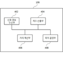
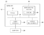
도 1은 본 발명의 일 실시예에 따른 위치 측정 시스템(100)의 상세 구성을 나타낸 블록도이다. 도 1에 도시된 바와 같이, 본 발명의 일 실시예에 따른 위치 측정 시스템(100)은 모바일 기기(102), 수신 장치(104), 서버(106) 및 데이터베이스(108)를 포함한다. 1 is a block diagram showing a detailed configuration of a
모바일 기기(102)는 사용자가 소지하는 단말로서, 수신 장치(104)와 신호를 송수신할 수 있다. 본 실시예들에 있어서, 모바일 기기(102)는 예를 들어, 스마트폰, PDA, 태블릿 PC, 노트북 등과 같은 휴대용 무선 통신 장치, 신호의 송수신이 가능한 웨어러블 디바이스 등이 될 수 있다. 또한, 상기 신호는 예를 들어, 와이파이(wifi) 신호, 블루투스(bluetooth) 신호 등과 같은 무선 주파수(RF : Radio Frequency) 신호일 수 있다.The
수신 장치(104)는 모바일 기기(102)를 감지하기 위한 장치로서, 모바일 기기(102)로 신호를 전송하고 상기 모바일 기기(102)로부터 신호를 수신할 수 있다. 이를 위해, 수신 장치(104)는 하나 이상의 지향성 안테나를 구비할 수 있으며, 상기 지향성 안테나를 이용하여 모바일 기기(102)로부터 신호를 수신할 수 있다. 지향성 안테나란 특정 방향으로 신호를 방사하거나 상기 특정 방향으로부터의 신호에 대한 수신 감도가 설정된 값 이상인 특성을 가지는 안테나이다. 본 실시예들에 있어서, 수신 장치(104)는 지향성 안테나를 구비하는 RF 수신기로서, 예를 들어, 무선 액세스포인트(AP : Access Point), 비콘(Beacon) 등이 될 수 있다. The receiving
수신 장치(104)는 대상 영역 내에 하나 이상 설치될 수 있다. 상기 대상 영역은 예를 들어, 백화점 내부, 사무실 등과 같은 실내 공간뿐 아니라 공원, 도로 등과 같은 실외 공간을 모두 포함하는 넓은 의미로 사용된다. 일 예시로서, 수신 장치(104)는 대상 영역 내 사용자가 이동 가능한 경로, 상기 경로의 분기점, 대상 영역 내 출입구 등에 설치될 수 있다. 이때, 지향성 안테나는 수신 장치(104)가 설치된 지점에서 연장되는 경로 측 신호를 설정된 값 이상의 수신 감도로 수신할 수 있다. 이를 위해, 관리자는 수신 장치(104)에서 상기 경로 측 신호를 수신할 수 있도록 지향성 안테나의 신호 수신 방향을 조정할 수 있다. 이하에서는, 지향성 안테나가 설정된 값 이상의 수신 감도로 신호를 감지할 수 있는 방향을 지향성 안테나의 “신호 감지 방향”이라 칭하기로 한다. 수신 장치(104)는 지향성 안테나의 신호 감지 방향 측 경로에 위치한 하나 이상의 모바일 기기(102) 각각으로부터 신호를 수신할 수 있다. 만약, 수신 장치(104)가 4개의 지향성 안테나를 구비하는 경우, 상기 지향성 안테나 각각은 서로 다른 방향의 경로 측 신호를 수신할 수 있다. 하나의 수신 장치(104)에 구비되는 지향성 안테나의 개수는 수신 장치(104)의 설치 위치, 상기 설치 위치에서 분기되는 경로의 개수, 상기 경로의 특성(예를 들어, 경로의 폭, 길이 등) 등에 따라 달라질 수 있다.At least one
수신 장치(104)는 모바일 기기(102) 각각으로부터 신호를 수신한 이후 상기 신호에 관한 정보를 서버(106)로 전송할 수 있다. 여기서, 상기 신호에 관한 정보는 모바일 기기(102)의 식별 정보, 수신된 신호의 세기(RSSI : Received Signal Strength Indication), 수신 장치(104)의 식별 정보 및 수신 장치(104)에서 상기 신호를 수신한 시각 중 하나 이상을 포함할 수 있다. 모바일 기기(102)의 식별 정보는 모바일 기기(102)를 식별하는 데 사용되는 정보로서, 예를 들어 모바일 기기(102)의 맥 어드레스(Mac Address), 모바일 기기(102)의 시리얼 넘버(Serial Number) 등이 될 수 있다. 또한, 수신 장치(104)의 식별 정보는 수신 장치(104)를 식별하는 데 사용되는 정보로서, 예를 들어 수신 장치(104)의 아이디(ID), 수신 장치(104)의 설치 위치를 나타내는 좌표 정보, 수신 장치(104)에 구비된 안테나의 아이디 등이 될 수 있다.The receiving
서버(106)는 상기 신호에 관한 정보를 수신 장치(104)로부터 수신하고, 상기 신호에 관한 정보를 기반으로 모바일 기기(102)의 위치를 결정한다. The
이를 위해, 서버(106)는 대상 영역을 나타내는 지도로부터 사용자가 이동 가능한 경로를 추출하고, 상기 경로 상에 존재하는 일 지점과 대응되는 노드(node) 및 상기 노드 사이를 연결하는 링크(link)로 이루어지는 가상의 경로 맵을 생성할 수 있다. 이때, 각 노드는 예를 들어, 경로의 분기점과 대응될 수 있다.To this end, the
서버(106)는 상기 경로 맵을 이용하여 모바일 기기(102)의 위치를 결정할 수 있다. 구체적으로, 서버(106)는 상기 경로 맵 및 상기 신호에 관한 정보를 이용하여 모바일 기기(102) 및 수신 장치(104) 사이의 거리를 계산하고, 상기 거리를 이용하여 모바일 기기(102)의 위치를 결정할 수 있다.The
먼저, 서버(106)는 모바일 기기(102) 및 수신 장치(104) 사이의 거리를 계산하기 위해 테스트 기기(미도시)를 이용하여 아래 수학식 1의 손실 신호 계수(N)를 산출할 수 있다.First, the
[수학식 1][Equation 1]
![]()
![]()
(여기서, d는 테스트 기기 및 수신 장치(104) 사이의 거리, TxPower는 수신 장치(104)에서의 송신하는 신호의 세기, RSSI는 수신 장치(104)에서 수신되는 신호의 세기, N은 손실 신호 계수를 각각 나타냄)(Where d is the distance between the test instrument and the
여기서, 테스트 기기는 손실 신호 계수(N)를 산출하는 데 사용되는 단말로서, 신호 송수신이 가능한 휴대용 무선 통신 장치, 웨어러블 디바이스 등이 될 수 있다. 상기 테스트 기기는 관리자에 의해 소지 또는 취급될 수 있다.Here, the test device may be a portable wireless communication device capable of transmitting and receiving signals, a wearable device, or the like, which is a terminal used for calculating the loss signal coefficient N. The test instrument may be owned or handled by an administrator.
먼저, 서버(106)는 경로 맵의 링크에 대응되는 경로 상에 위치한 테스트 기기의 위치가 변경됨에 따라 수학식 1을 이용하여 테스트 기기 및 수신 장치(104) 사이의 거리를 각각 계산할 수 있다. 이를 위해, 관리자는 테스트 기기를 소지한 채 경로 맵의 링크에 대응되는 경로 상에서 이동할 수 있으며, 이에 따라 경로 상에 위치한 테스트 기기의 위치가 변경될 수 있다. 서버(106)는 해당 위치에서 테스트 기기와 수신 장치(104) 사이의 실제 거리, 수신 장치(104)에서 테스트 기기로부터 수신된 신호의 세기(RSSI), 수신 장치(104)에서 상기 신호를 수신한 시각(T1, T2, T3…등)을 각각 기록하고, 수학식 1을 이용하여 해당 시각에서의 테스트 기기와 수신 장치(104) 사이의 거리(예를 들어, d1, d2, d3…등)를 각각 계산할 수 있다. 이때, TxPower는 수신 장치(104)가 모바일 기기(102)로 전송하는 신호의 세기로서 미리 설정된 값(예를 들어, -20dB)이며, RSSI는 테스트 기기의 위치에 따라 달라질 수 있다. 또한, 서버(106)는 미리 설정된 초기값을 손실 신호 계수(N)로서 활용할 수 있다. First, the
다음으로, 서버(106)는 테스트 기기 및 수신 장치(104) 사이의 거리와 테스트 기기 및 수신 장치(104) 사이의 실제 거리의 차의 합이 최소가 되는 손실 신호 계수(N)을 산출할 수 있다. Next, the
일 예시로서, T1, T2 및 T3에서 테스트 기기와 수신 장치(104) 사이의 실제 거리(p1, p2, p3)가 서버(106)에 기록된 경우, 서버(106)는 T1에서 수학식 1을 계산하여 획득한 d1, T2에서 수학식 1을 계산하여 획득한 d2, T3에서 수학식 1을 계산하여 획득한 d3 각각을 획득하고, |p1-d1| + |p2-d2| +|p3-d3| = l1 +l2 +l3 를 계산할 수 있다. 여기서, l1, l2, l3는 수학식 1을 이용하여 계산된 테스트 기기 및 수신 장치(104) 사이의 거리(d1, d2, d3)와 테스트 기기 및 수신 장치(104) 사이의 실제 거리(p1, p2, p3)의 차를 각각 나타낸다. 한편, 여기서는 설명의 편의상 계산된 테스트 기기 및 수신 장치(104) 사이의 거리(d1, d2, d3)와 테스트 기기 및 수신 장치(104) 사이의 실제 거리(p1, p2, p3)의 차의 합를 |p1-d1| + |p2-d2| +|p3-d3|로 나타내었으나, 이는 일 실시예에 불과하며 상기 차의 합은 ![]()
![]()
서버(106)는 손실 신호 계수(N)를 변경해 가면서 테스트 기기 및 수신 장치(104) 사이의 거리와 테스트 기기 및 수신 장치(104) 사이의 실제 거리의 차의 합(예를 들어, l1 +l2 +l3)을 각각 계산할 수 있으며, 상기 계산은 설정된 횟수만큼 반복될 수 있다. 예를 들어, 서버(106)는 N1에서의 l1 +l2 +l3, N2에서의 l1 +l2 +l3, N3에서의 l1 +l2 +l3… 등을 각각 계산할 수 있다. 서버(106)는 상기 계산 결과 테스트 기기 및 수신 장치(104) 사이의 거리와 테스트 기기 및 수신 장치(104) 사이의 실제 거리의 차의 합(예를 들어, l1 + l2 + l3)이 최소가 되는 손실 신호 계수(N)를 산출할 수 있다. 이와 같은 과정을 통해 산출된 손실 신호 계수(N)는 모바일 기기(102) 및 수신 장치(104) 사이의 거리를 계산하는 데 사용될 수 있다.The
서버(106)는 산출된 상기 손실 신호 계수(N)를 다음의 수학식 2에 적용함으로써 모바일 기기(102) 및 수신 장치(104) 사이의 거리를 계산할 수 있다.The
[수학식 2]&Quot; (2) "
(여기서, d'는 모바일 기기(102) 및 수신 장치(104) 사이의 거리, TxPower는 수신 장치(104)에서의 송신하는 신호의 세기, RSSI는 수신 장치(104)에서 수신되는 신호의 세기, N은 손실 신호 계수를 각각 나타냄)(Where d 'is the distance between the
이때, TxPower는 수신 장치(104)가 모바일 기기(102)로 전송하는 신호의 세기로서 미리 설정된 값(예를 들어, -20dB)이며, RSSI는 모바일 기기(102)의 위치에 따라 달라질 수 있다. 본 발명의 실시예들에 따르면, 테스트 기기를 이용하여 거리 계산시 사용되는 최적의 손실 신호 계수(N)를 산출하고 산출된 상기 손실 신호 계수(N)를 이용하여 모바일 기기(102) 및 수신 장치(104) 사이의 거리를 계산하도록 함으로써, 계산된 모바일 기기(102) 및 수신 장치(104) 사이의 거리와 모바일 기기(102) 및 수신 장치(104) 사이의 실제 거리 간의 오차를 최소화할 수 있다.In this case, TxPower is a predetermined value (for example, -20 dB) as a strength of a signal transmitted from the receiving
또한, 서버(106)는 계산된 상기 모바일 기기(102) 및 수신 장치(104) 사이의 거리를 이용하여 모바일 기기(102)의 위치를 결정할 수 있다. 구체적으로, 서버(106)는 수신 장치(104)를 경로 맵 상의 대응되는 일 노드에 매칭시키며, 상기 노드로부터의 거리가 계산된 상기 모바일 기기(102) 및 수신 장치(104) 사이의 거리에 해당하는 상기 링크 상의 일 지점을 모바일 기기(102)의 위치로 결정할 수 있다. 즉, 서버(106)는 계산된 상기 모바일 기기(102) 및 수신 장치(104) 사이의 거리에 따라 모바일 기기(102)를 링크 상의 일 지점에 매칭시킬 수 있으며, 이 경우 경로 상에 존재하는 모바일 기기(102)는 상기 링크 상에 모두 매칭되게 된다.The
또한, 서버(106)는 결정된 상기 모바일 기기(102)의 위치를 이용하여 경로의 혼잡도, 모바일 기기(102)의 동선 및 체류 시간 중 하나 이상을 획득할 수 있다. The
일 예시로서, 서버(106)는 상기 링크 상에 존재하는 모바일 기기(102)의 개수를 산출하고, 상기 모바일 기기(102)의 개수로부터 해당 경로의 혼잡도를 획득할 수 있다. As an example, the
다른 예시로서, 서버(106)는 모바일 기기(102)의 위치 및 수신 장치(104)에서 신호를 수신한 시각으로부터 모바일 기기(102)의 동선 및 체류 시간을 획득할 수 있다. As another example, the
또한, 서버(106)는 상기 경로의 혼잡도, 모바일 기기(102)의 동선 및 체류 시간 중 하나 이상을 디스플레이할 수 있다. 관리자는 서버(106)에서 디스플레이되는 정보들을 모니터링함으로써, 모바일 기기(102)가 위치하는 경로의 혼잡도, 모바일 기기(102)의 위치, 동선 및 체류 시간 등을 보다 용이하게 파악할 수 있다.In addition, the
데이터베이스(108)는 서버(106)에서 산출된 손실 신호 계수(N), 서버(106)에서 결정된 모바일 기기(102)의 위치 정보 등이 저장되는 저장소이다. 서버(106)는 테스트 기기 및 수신 장치(104) 사이의 거리와 테스트 기기 및 수신 장치(104) 사이의 실제 거리의 차의 합이 최소가 되는 손실 신호 계수(N)을 산출하고, 산출된 손실 신호 계수(N)를 데이터베이스(108)에 저장할 수 있다. 또한, 서버(106)는 계산된 상기 모바일 기기(102) 및 수신 장치(104) 사이의 거리를 이용하여 모바일 기기(102)의 위치를 결정하고, 모바일 기기(102)의 위치 정보(예를 들어, 링크 상의 모바일 기기(102)의 위치 좌표)를 데이터베이스(108)에 저장할 수 있다. 한편, 도 1에서는 설명의 편의상 데이터베이스(108)가 서버(106)와 별도의 구성인 것으로 도시하였으나, 이는 일 실시예에 불과하며 데이터베이스(108)는 서버(106)의 일 구성으로서 존재할 수도 있다.The
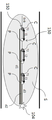
도 2는 일반적인 무지향성 안테나의 무지향성 특성을 나타낸 도면이며, 도 3은 본 발명의 일 실시예에 따른 지향성 안테나의 지향성 특성을 나타낸 도면이다. FIG. 2 is a diagram illustrating omnidirectional characteristics of a general omnidirectional antenna, and FIG. 3 is a diagram illustrating a directional characteristic of a directional antenna according to an embodiment of the present invention.
도 2를 참조하면, 일반적인 무지향성 안테나는 360도 전방향의 신호를 감지하는 특성을 가진다. 무지향성 안테나를 사용하여 모바일 기기(102)의 위치를 측정하는 경우, 신호 감지 범위가 넓어지는 만큼 감지 가능한 거리는 짧아지고 주변 환경에 의한 잡음이 생길 확률이 높아지게 된다. 또한, 이 경우 신호가 중복되어 감지될 수 있으며 전파 특성(반사, 산란, 회절, 굴절 등)으로 인해 측정된 모바일 기기(102)의 위치와 모바일 기기(102)의 실제 위치 간에 오차가 발생할 확률이 증가하게 된다. 또한, 무지향성 안테나 각각에서 신호를 감지함에 따라, 측정된 모바일 기기(102)의 위치가 산재되어 모바일 기기(102)의 동선 및 체류 시간의 파악에 어려움이 있을 수 있다.Referring to FIG. 2, a general omnidirectional antenna has a characteristic of sensing a signal in 360 degrees forward direction. When the position of the
이와 같은 문제점을 해결하기 위해, 본 발명의 일 실시예에 따른 수신 장치(104)는 하나 이상의 지향성 안테나를 구비하고, 상기 지향성 안테나를 이용하여 모바일 기기(102)의 위치를 측정할 수 있다. 이때, 지향성 안테나 각각은 서로 다른 방향의 경로 측 신호를 수신할 수 있다.In order to solve such a problem, the receiving
도 3에 도시된 바와 같이, 지향성 안테나는 특정 방향으로 신호를 방사하거나 상기 특정 방향으로부터의 신호에 대한 수신 감도가 설정된 값 이상인 특성을 가진다. 따라서, 지향성 안테나를 사용하여 모바일 기기(102)의 위치를 측정하는 경우, 전파의 특성 및 주변 환경으로 인한 영향을 최소화할 수 있으며 신호가 중복되어 감지되는 위험을 사전에 차단할 수 있다. 이 경우, 모바일 기기(102)의 동선 및 체류 시간을 보다 용이하게 파악할 수 있다.As shown in Fig. 3, the directional antenna has a characteristic in which a signal is radiated in a specific direction or a reception sensitivity for a signal from the specific direction is set or higher. Therefore, when the position of the
도 4는 본 발명의 일 실시예에 따른 서버(106)의 상세 구성을 나타낸 블록도이다. 도 4에 도시된 바와 같이, 본 발명의 일 실시예에 따른 서버(106)는 신호 정보 수신부(402), 계수 산출부(404), 거리 계산부(406) 및 위치 결정부(208)를 포함한다.4 is a block diagram showing a detailed configuration of a
신호 정보 수신부(402)는 수신 장치(104)에서 모바일 기기(102)로부터 수신된 신호에 관한 정보를 수신 장치(104)로부터 수신한다. 상기 신호에 관한 정보는 모바일 기기(102)의 식별 정보, 수신된 신호의 세기(RSSI), 수신 장치(104)의 식별 정보 및 수신 장치(104)에서 상기 신호를 수신한 시각 중 하나 이상을 포함할 수 있다.The signal
계수 산출부(404)는 모바일 기기(102) 및 수신 장치(104) 사이의 거리 계산을 위한 손실 신호 계수(N)를 계산한다. 구체적으로, 계수 산출부(404)는 경로 맵의 링크에 대응되는 경로 상에 위치한 테스트 기기의 위치가 변경됨에 따라 상술한 수학식 1을 이용하여 테스트 기기 및 수신 장치(104) 사이의 거리를 각각 계산하고, 테스트 기기 및 수신 장치(104) 사이의 거리와 테스트 기기 및 수신 장치(104) 사이의 실제 거리의 차의 합이 최소가 되는 손실 신호 계수(N)을 산출할 수 있다. 이후, 계수 산출부(404)는 산출된 손실 신호 계수(N)를 데이터베이스(108)에 저장할 수 있다.The
거리 계산부(406)는 산출된 손실 신호 계수(N)를 이용하여 모바일 기기(102) 및 수신 장치(104) 사이의 거리를 계산한다. 구체적으로, 거리 계산부(406)는 산출된 손실 신호 계수(N)를 상술한 수학식 2에 적용함으로써 모바일 기기(102) 및 수신 장치(104) 사이의 거리를 계산할 수 있다.The
위치 결정부(408)는 계산된 상기 모바일 기기(102) 및 수신 장치(104) 사이의 거리를 이용하여 모바일 기기(102)의 위치를 결정할 수 있다. 구체적으로, 서버(106)는 수신 장치(104)를 경로 맵 상의 대응되는 일 노드에 매칭시키며, 상기 노드로부터의 거리가 계산된 상기 모바일 기기(102) 및 수신 장치(104) 사이의 거리에 해당하는 상기 링크 상의 일 지점을 모바일 기기(102)의 위치로 결정할 수 있다. 이후, 위치 결정부(408)는 결정된 모바일 기기(102)의 위치 정보를 데이터베이스(108)에 저장할 수 있다.The
도 5는 본 발명의 일 실시예에 따른 경로 맵의 예시도이다. 상술한 바와 같이, 서버(106)는 대상 영역을 나타내는 지도로부터 사용자가 이동 가능한 경로를 추출하고, 상기 경로로부터 가상의 경로 맵을 생성할 수 있다.5 is an exemplary diagram of a path map according to an embodiment of the present invention. As described above, the
도 5에 도시된 바와 같이, 서버(106)는 상기 경로 상에 존재하는 일 지점과 대응되는 노드(node) 및 상기 노드 사이를 연결하는 링크(link)로 이루어지는 가상의 경로 맵을 생성할 수 있다. 이때, 각 노드는 예를 들어, 경로의 분기점과 대응될 수 있다.As shown in FIG. 5, the
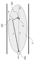
도 6은 본 발명의 일 실시예에 따른 서버(106)에서 모바일 기기(102) 및 수신 장치(104) 사이의 거리를 계산하기 위해 손실 신호 계수(N)를 산출하는 과정을 설명하기 위한 도면이다.6 is a diagram for explaining a process of calculating a loss signal coefficient N to calculate the distance between the
도 6에 도시된 바와 같이, 서버(106)는 경로 맵의 링크(link)에 대응되는 경로 상에 위치한 테스트 기기(150)의 위치가 변경됨에 따라 수학식 1을 이용하여 테스트 기기(150) 및 수신 장치(104) 사이의 거리를 각각 계산할 수 있다. 여기서, 영역 S는 지향성 안테나의 신호 감지 범위를 나타낸다.As shown in FIG. 6, when the location of the
이를 위해, 관리자는 테스트 기기(150)를 소지한 채 경로 맵의 링크에 대응되는 경로 상에서 이동할 수 있으며, 이에 따라 경로 상에 위치한 테스트 기기(150)의 위치가 변경될 수 있다. 서버(106)는 해당 위치에서 테스트 기기(150)와 수신 장치(104) 사이의 실제 거리, 수신 장치(104)에서 테스트 기기(150)로부터 수신된 신호의 세기(RSSI), 수신 장치(104)에서 상기 신호를 수신한 시각(T1, T2, T3…등)을 각각 기록하고, 수학식 1을 이용하여 해당 시각에서의 테스트 기기(150)와 수신 장치(104) 사이의 거리(예를 들어, d1, d2, d3…등)를 각각 계산할 수 있다. 이때, TxPower는 수신 장치(104)가 테스트 기기(150)로 전송하는 신호의 세기로서 미리 설정된 값이며, RSSI는 테스트 기기(150)의 위치에 따라 달라질 수 있다. 또한, 서버(106)는 미리 설정된 초기값을 손실 신호 계수(N)로서 활용할 수 있다. To this end, the administrator can move on the path corresponding to the link of the path map with the
다음으로, 서버(106)는 테스트 기기(150) 및 수신 장치(104) 사이의 거리와 테스트 기기 및 수신 장치(104) 사이의 실제 거리의 차의 합이 최소가 되는 손실 신호 계수(N)을 산출할 수 있다. Next, the
일 예시로서, T1, T2 및 T3에서 테스트 기기와 수신 장치(104) 사이의 실제 거리(p1, p2, p3)가 서버(106)에 기록된 경우, 서버(106)는 T1에서 수학식 1을 계산하여 획득한 d1, T2에서 수학식 1을 계산하여 획득한 d2, T3에서 수학식 1을 계산하여 획득한 d3 각각을 획득하고, |p1-d1| + |p2-d2| +|p3-d3| = l1 +l2 +l3 를 계산할 수 있다. 여기서, l1, l2, l3는 수학식 1을 이용하여 계산된 테스트 기기 및 수신 장치(104) 사이의 거리(d1, d2, d3)와 테스트 기기 및 수신 장치(104) 사이의 실제 거리(p1, p2, p3)의 차를 각각 나타낸다. 도 6에 표시된 P는 테스트 기기(150)의 실제 위치를 나타내며, C는 RSSI에 의해 계산된 테스트 기기(150)의 측정 위치를 나타낸다.As an example, if the actual distances (p1, p2, p3) between the test device and the receiving
서버(106)는 손실 신호 계수(N)를 변경해 가면서 테스트 기기 및 수신 장치(104) 사이의 거리와 테스트 기기 및 수신 장치(104) 사이의 실제 거리의 차의 합(예를 들어, l1 +l2 +l3)을 각각 계산할 수 있으며, 상기 계산은 설정된 횟수만큼 반복될 수 있다. 예를 들어, 서버(106)는 N1에서의 l1 +l2 +l3, N2에서의 l1 +l2 +l3, N3에서의 l1 +l2 +l3… 등을 각각 계산할 수 있다. 서버(106)는 상기 계산 결과 테스트 기기 및 수신 장치(104) 사이의 거리와 테스트 기기 및 수신 장치(104) 사이의 실제 거리의 차의 합(예를 들어, l1 + l2 + l3)이 최소가 되는 손실 신호 계수(N)를 산출할 수 있다. 이와 같은 과정을 통해 산출된 손실 신호 계수(N)는 모바일 기기(102) 및 수신 장치(104) 사이의 거리를 계산하는 데 사용될 수 있다.The
도 7은 본 발명의 일 실시예에 따른 서버(106)에서 모바일 기기(102)의 위치를 결정하는 과정을 설명하기 위한 도면이다. 상술한 바와 같이, 서버(106)는 산출된 손실 신호 계수(N)를 상술한 수학식 2에 적용함으로써 모바일 기기(102) 및 수신 장치(104) 사이의 거리(d')를 계산할 수 있다.FIG. 7 is a diagram illustrating a process of determining the location of the
도 7을 참조하면, 서버(106)는 계산된 상기 모바일 기기(102) 및 수신 장치(104) 사이의 거리(d')를 이용하여 모바일 기기(102)의 위치를 결정할 수 있다. 구체적으로, 서버(106)는 수신 장치(104)를 경로 맵 상의 대응되는 일 노드에 매칭시키며, 상기 노드로부터의 거리가 계산된 상기 모바일 기기(102) 및 수신 장치(104) 사이의 거리(d')에 해당하는 상기 링크 상의 일 지점(C')을 모바일 기기(102)의 위치로 결정할 수 있다. 도 7에 표시된 P'는 모바일 기기(150)의 실제 위치를 나타내며, C'는 경로 맵의 링크 상에 매칭된 모바일 기기(150)의 위치를 나타낸다.Referring to FIG. 7, the
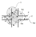
도 8은 일반적인 위치 측정 방식을 설명하기 위한 도면이며, 도 9는 본 발명의 일 실시예에 따른 위치 측정 방식을 설명하기 위한 도면이다.FIG. 8 is a view for explaining a general position measuring method, and FIG. 9 is a view for explaining a position measuring method according to an embodiment of the present invention.
도 8을 참조하면, 일반적으로 실내 측위 방식으로서 삼변 측위(Trilateration), 삼각 측위(Triangulation), 또는 핑거프린트(Fingerprint) 측위 방식이 사용된다. 그러나, 이 경우 다수의 RF 수신기(704)가 필요하게 되며 번거로운 측위 과정이 수반된다. 구체적으로, 삼변 측위 방식 및 삼각 측위 방식의 경우 최소 3개의 RF 수신기(704)가 필요하게 되며, 핑거프린트 측위 방식의 경우 다수의 RF 수신기(704)가 필요할 뿐 아니라 각 위치에서의 핑거프린트를 사전에 미리 수집하여야 하는 번거로움이 있다. 나아가, 종래 측위 방식에 따르면, RF 수신기(704)가 무지향성 안테나를 사용하여 신호를 감지하게 되므로, 모바일 기기(702)의 위치 측정시 전파의 특성 및 주변 환경에 많은 영향을 받게 되며 신호가 중복되어 감지되는 위험이 발생하게 된다. 본 발명의 일 실시예에 따른 측위 방식은 이러한 종래 측위 방식의 문제점을 해결할 수 있다. 도 8에 표시된 P'는 모바일 기기(702)의 실제 위치를 나타내며, C'는 삼변 측위 방식, 삼각 측위 방식, 핑거프린트 측위 방식 등에 의해 측정된 모바일 기기(702)의 위치를 나타낸다.Referring to FIG. 8, a trilateration, a triangulation, or a fingerprint positioning method is generally used as an indoor positioning method. However, in this case, a large number of
도 9에 도시된 바와 같이, 본 발명의 실시예들에 따르면, 지향성 안테나를 구비하는 하나의 수신 장치(104)를 이용하여 각 경로(또는 링크)별로 모바일 기기(102)의 위치를 측정할 수 있다. 도 9에 표시된 P'는 모바일 기기(150)의 실제 위치를 나타내며, C'는 경로 맵의 링크 상에 매칭된 모바일 기기(150)의 위치를 나타낸다. 상술한 바와 같이, 서버(106)는 수학식 1 및 2로부터 계산된 모바일 기기(102) 및 수신 장치(104) 사이의 거리에 따라 모바일 기기(102)를 링크 상의 일 지점에 매칭시킬 수 있으며, 이 경우 경로 상에 존재하는 모바일 기기(102)는 상기 링크 상에 모두 매칭되게 된다.9, according to embodiments of the present invention, a
또한, 서버(106)는 결정된 상기 모바일 기기(102)의 위치(즉, 링크 상에 매칭된 모바일 기기의 위치)를 이용하여 경로의 혼잡도, 모바일 기기(102)의 동선 및 체류 시간 중 하나 이상을 획득할 수 있다. In addition, the
일 예시로서, 서버(106)는 상기 링크 상에 존재하는 모바일 기기(102)의 개수를 산출하고, 상기 모바일 기기(102)의 개수로부터 해당 경로의 혼잡도를 획득할 수 있다. 예를 들어, 제1 경로에 대응되는 제1 링크 상에 존재하는 모바일 기기(102)의 개수가 3개인 경우 제1 경로의 혼잡도는 3일 수 있으며, 제2 경로에 대응되는 제2 링크 상에 존재하는 모바일 기기(102)의 개수가 9개인 경우 제2 경로의 혼잡도는 9일 수 있다.As an example, the
다른 예시로서, 서버(106)는 모바일 기기(102)의 위치 및 수신 장치(104)에서 신호를 수신한 시각으로부터 모바일 기기(102)의 동선 및 체류 시간을 획득할 수 있다. 예를 들어, T1~T2 에 모바일 기기(102)가 제1 경로에 대응되는 제1 링크 상에 존재하고 T2~T3 에 모바일 기기(102)가 제2 경로에 대응되는 제2 링크 상에 존재하는 것으로 가정하는 경우, 서버(106)는 모바일 기기(102)가 제1 경로 → 제2 경로로 이동한 것으로 판단하고 제1 경로 및 제2 경로에서의 모바일 기기(102)의 체류 시간(즉, T2-T1, T3-T2)을 각각 계산할 수 있다.As another example, the
또한, 서버(106)는 상기 경로의 혼잡도, 모바일 기기(102)의 동선 및 체류 시간 중 하나 이상을 디스플레이할 수 있다. 관리자는 서버(106)에서 디스플레이되는 정보들을 모니터링함으로써, 모바일 기기(102)가 위치하는 경로의 혼잡도, 모바일 기기(102)의 위치, 동선 및 체류 시간 등을 보다 용이하게 파악할 수 있다.In addition, the
도 10은 예시적인 실시예들에서 사용되기에 적합한 컴퓨팅 장치를 포함하는 컴퓨팅 환경을 예시하여 설명하기 위한 블록도이다. 도시된 실시예에서, 각 컴포넌트들은 이하에 기술된 것 이외에 상이한 기능 및 능력을 가질 수 있고, 이하에 기술되지 것 이외에도 추가적인 컴포넌트를 포함할 수 있다.10 is a block diagram illustrating and illustrating a computing environment including a computing device suitable for use in the exemplary embodiments. In the illustrated embodiment, each component may have different functions and capabilities than those described below, and may include additional components in addition to those described below.
도시된 컴퓨팅 환경(10)은 컴퓨팅 장치(12)를 포함한다. 일 실시예에서, 컴퓨팅 장치(12)는 위치 측정 시스템(100), 또는 위치 측정 시스템(100)에 포함되는 하나 이상의 컴포넌트일 수 있다. The illustrated
컴퓨팅 장치(12)는 적어도 하나의 프로세서(14), 컴퓨터 판독 가능 저장 매체(16) 및 통신 버스(18)를 포함한다. 프로세서(14)는 컴퓨팅 장치(12)로 하여금 앞서 언급된 예시적인 실시예에 따라 동작하도록 할 수 있다. 예컨대, 프로세서(14)는 컴퓨터 판독 가능 저장 매체(16)에 저장된 하나 이상의 프로그램들을 실행할 수 있다. 상기 하나 이상의 프로그램들은 하나 이상의 컴퓨터 실행 가능 명령어를 포함할 수 있으며, 상기 컴퓨터 실행 가능 명령어는 프로세서(14)에 의해 실행되는 경우 컴퓨팅 장치(12)로 하여금 예시적인 실시예에 따른 동작들을 수행하도록 구성될 수 있다.The
컴퓨터 판독 가능 저장 매체(16)는 컴퓨터 실행 가능 명령어 내지 프로그램 코드, 프로그램 데이터 및/또는 다른 적합한 형태의 정보를 저장하도록 구성된다. 컴퓨터 판독 가능 저장 매체(16)에 저장된 프로그램(20)은 프로세서(14)에 의해 실행 가능한 명령어의 집합을 포함한다. 일 실시예에서, 컴퓨터 판독 가능 저장 매체(16)는 메모리(랜덤 액세스 메모리와 같은 휘발성 메모리, 비휘발성 메모리, 또는 이들의 적절한 조합), 하나 이상의 자기 디스크 저장 디바이스들, 광학 디스크 저장 디바이스들, 플래시 메모리 디바이스들, 그 밖에 컴퓨팅 장치(12)에 의해 액세스되고 원하는 정보를 저장할 수 있는 다른 형태의 저장 매체, 또는 이들의 적합한 조합일 수 있다.The computer-
통신 버스(18)는 프로세서(14), 컴퓨터 판독 가능 저장 매체(16)를 포함하여 컴퓨팅 장치(12)의 다른 다양한 컴포넌트들을 상호 연결한다.
컴퓨팅 장치(12)는 또한 하나 이상의 입출력 장치(24)를 위한 인터페이스를 제공하는 하나 이상의 입출력 인터페이스(22) 및 하나 이상의 네트워크 통신 인터페이스(26)를 포함할 수 있다. 입출력 인터페이스(22) 및 네트워크 통신 인터페이스(26)는 통신 버스(18)에 연결된다. 입출력 장치(24)는 입출력 인터페이스(22)를 통해 컴퓨팅 장치(12)의 다른 컴포넌트들에 연결될 수 있다. 예시적인 입출력 장치(24)는 포인팅 장치(마우스 또는 트랙패드 등), 키보드, 터치 입력 장치(터치패드 또는 터치스크린 등), 음성 또는 소리 입력 장치, 다양한 종류의 센서 장치 및/또는 촬영 장치와 같은 입력 장치, 및/또는 디스플레이 장치, 프린터, 스피커 및/또는 네트워크 카드와 같은 출력 장치를 포함할 수 있다. 예시적인 입출력 장치(24)는 컴퓨팅 장치(12)를 구성하는 일 컴포넌트로서 컴퓨팅 장치(12)의 내부에 포함될 수도 있고, 컴퓨팅 장치(12)와는 구별되는 별개의 장치로 컴퓨팅 장치(102)와 연결될 수도 있다.The
도 11은 본 발명의 일 실시예에 따른 위치 측정 방법을 설명하기 위한 도면이다. 도시된 흐름도에서는 상기 방법을 복수 개의 단계로 나누어 기재하였으나, 적어도 일부의 단계들은 순서를 바꾸어 수행되거나, 다른 단계와 결합되어 함께 수행되거나, 생략되거나, 세부 단계들로 나뉘어 수행되거나, 또는 도시되지 않은 하나 이상의 단계가 부가되어 수행될 수 있다.11 is a view for explaining a position measuring method according to an embodiment of the present invention. In the illustrated flow chart, the method is described as being divided into a plurality of steps, but at least some of the steps may be performed in reverse order, combined with other steps, performed together, omitted, divided into detailed steps, One or more steps may be added and performed.
먼저, 수신 장치(104)는 모바일 기기(102)로부터 신호를 수신한다(S1102). 상술한 바와 같이, 수신 장치(104)는 하나 이상의 지향성 안테나를 구비할 수 있으며, 상기 지향성 안테나의 신호 감지 방향 측 경로에 위치한 하나 이상의 모바일 기기(102) 각각으로부터 신호를 수신할 수 있다.First, the receiving
다음으로, 수신 장치(104)는 상기 신호에 관한 정보를 서버(106)로 전송한다(S1104). 상기 신호에 관한 정보는 모바일 기기(102)의 식별 정보, 수신된 신호의 세기(RSSI), 수신 장치(104)의 식별 정보 및 수신 장치(104)에서 상기 신호를 수신한 시각 중 하나 이상을 포함할 수 있다.Next, the receiving
다음으로, 서버(106)는 모바일 기기(102) 및 수신 장치(104) 사이의 거리 계산을 위한 손실 신호 계수(N)를 산출한다(S1106). 서버(106)는 경로 맵의 링크에 대응되는 경로 상에 위치한 테스트 기기의 위치가 변경됨에 따라 상술한 수학식 1을 이용하여 테스트 기기 및 수신 장치(104) 사이의 거리를 각각 계산하고, 테스트 기기 및 수신 장치(104) 사이의 거리와 테스트 기기 및 수신 장치(104) 사이의 실제 거리의 차의 합이 최소가 되는 손실 신호 계수(N)을 산출할 수 있다.Next, the
다음으로, 서버(106)는 산출된 손실 신호 계수(N)를 이용하여 모바일 기기(102) 및 수신 장치(104) 사이의 거리를 계산한다(S1108). 구체적으로, 서버(106)는 산출된 손실 신호 계수(N)를 상술한 수학식 2에 적용함으로써 모바일 기기(102) 및 수신 장치(104) 사이의 거리를 계산할 수 있다.Next, the
다음으로, 서버(106)는 계산된 상기 모바일 기기(102) 및 수신 장치(104) 사이의 거리를 이용하여 모바일 기기(102)의 위치를 결정한다(S1110). 구체적으로, 서버(106)는 수신 장치(104)를 경로 맵 상의 대응되는 일 노드에 매칭시키며, 계산된 상기 모바일 기기(102) 및 수신 장치(104) 사이의 거리에 따라 모바일 기기(102)를 링크 상의 일 지점에 매칭시킬 수 있다.Next, the
마지막으로, 서버(106)는 결정된 모바일 기기(102)의 위치를 이용하여 상기 링크에 속성값을 부여한다(S1112). 여기서, 속성값은 경로의 속성을 나타내는 정보로서, 예를 들어 경로의 혼잡도일 수 있다. 서버(106)는 링크 상에 존재하는 모바일 기기(102)의 개수를 산출하고, 모바일 기기(102)의 개수로부터 경로의 혼잡도를 획득할 수 있다. 또한, 서버(106)는 모바일 기기(102)의 위치 및 수신 장치(104)에서 신호를 수신한 시각으로부터 모바일 기기(102)의 동선 및 체류 시간을 획득할 수도 있다. Lastly, the
이상에서 대표적인 실시예를 통하여 본 발명에 대하여 상세하게 설명하였으나, 본 발명이 속하는 기술분야에서 통상의 지식을 가진 자는 전술한 실시예에 대하여 본 발명의 범주에서 벗어나지 않는 한도 내에서 다양한 변형이 가능함을 이해할 것이다. 그러므로 본 발명의 권리범위는 설명된 실시예에 국한되어 정해져서는 안 되며, 후술하는 특허청구범위뿐만 아니라 이 특허청구범위와 균등한 것들에 의해 정해져야 한다.While the present invention has been particularly shown and described with reference to exemplary embodiments thereof, it is to be understood that the invention is not limited to the disclosed embodiments, but, on the contrary, I will understand. Therefore, the scope of the present invention should not be limited to the above-described embodiments, but should be determined by equivalents to the appended claims, as well as the appended claims.
10 : 컴퓨팅 환경
12 : 컴퓨팅 장치
14 : 프로세서
16 : 컴퓨터 판독 가능 저장 매체
20 : 프로그램
22 : 입출력 인터페이스
24 : 입출력 장치
26 : 네트워크 통신 인터페이스
100 : 위치 측정 시스템
102, 702 : 모바일 기기
104: 수신 장치
106 : 서버
108 : 데이터베이스
150 : 테스트 기기
402 : 신호 정보 수신부
404 : 계수 산출부
406 : 거리 계산부
408 : 위치 결정부
704 : RF 수신기10: Computing environment
12: computing device
14: Processor
16: Computer readable storage medium
20: Program
22: I / O interface
24: input / output device
26: Network communication interface
100: Position measurement system
102, 702: Mobile device
104: Receiver
106: Server
108: Database
150: Test equipment
402: Signal information receiver
404: coefficient calculation unit
406: Distance calculation unit
408:
704: RF receiver
Claims (12)
상기 신호에 관한 정보를 상기 수신 장치로부터 수신하고, 상기 신호에 관한 정보를 기반으로 상기 모바일 기기의 위치를 결정하며, 상기 위치를 이용하여 상기 경로의 혼잡도를 획득하는 서버를 포함하는, 위치 측정 시스템.
A receiving device having a directional antenna and receiving a signal from each of one or more mobile devices located in a signal-sensing direction-side path of the directional antenna; And
A server for receiving information about the signal from the receiving device, determining a location of the mobile device based on information about the signal, and using the location to obtain a congestion of the path, .
상기 신호에 관한 정보는, 상기 모바일 기기의 식별 정보, 상기 신호의 세기(RSSI : Received Signal Strength Indication), 상기 수신 장치의 식별 정보 및 상기 수신 장치에서 상기 신호를 수신한 시각 중 하나 이상을 포함하는, 위치 측정 시스템.
The method according to claim 1,
Wherein the information on the signal includes at least one of identification information of the mobile device, received signal strength indication (RSSI), identification information of the receiving device, and time at which the signal was received at the receiving device , Position measurement system.
상기 서버는, 상기 신호에 관한 정보를 이용하여 상기 모바일 기기 및 상기 수신 장치 사이의 거리를 계산하고, 상기 거리를 이용하여 상기 모바일 기기의 위치를 결정하는, 위치 측정 시스템.
The method of claim 2,
Wherein the server calculates the distance between the mobile device and the receiving device using information about the signal and determines the location of the mobile device using the distance.
상기 서버는, 상기 경로에 위치한 테스트 기기의 위치가 변경됨에 따라 아래의 수학식 1을 이용하여 상기 테스트 기기 및 상기 수신 장치 사이의 거리를 각각 계산하고, 계산된 상기 테스트 기기 및 상기 수신 장치 사이의 거리와 상기 테스트 기기 및 상기 수신 장치 사이의 실제 거리의 차의 합이 최소가 되는 손실 신호 계수(N)을 산출하는, 위치 측정 시스템.
[수학식 1]
(여기서, d는 상기 테스트 기기 및 상기 수신 장치 사이의 거리, TxPower는 상기 수신 장치에서의 송신하는 신호의 세기, RSSI는 상기 수신 장치에서 수신되는 신호의 세기, N은 손실 신호 계수를 각각 나타냄)
The method of claim 3,
The server calculates the distance between the test apparatus and the receiving apparatus by using the following Equation 1 as the position of the test apparatus located in the path is changed and calculates a distance between the test apparatus and the receiving apparatus, And calculates a loss signal coefficient (N) at which a sum of a distance and an actual distance between the test apparatus and the receiving apparatus is minimized.
[Equation 1]
(Where d is the distance between the test device and the receiver, TxPower is the intensity of the signal transmitted by the receiver, RSSI is the intensity of the signal received by the receiver, and N is the loss signal coefficient)
상기 서버는, 산출된 상기 손실 신호 계수(N)를 다음의 수학식 2에 적용함으로써 상기 모바일 기기 및 상기 수신 장치 사이의 거리를 계산하는, 위치 측정 시스템.
[수학식 2]

(여기서, d'는 상기 모바일 기기 및 상기 수신 장치 사이의 거리, TxPower는 상기 수신 장치에서의 송신하는 신호의 세기, RSSI는 상기 수신 장치에서 수신되는 신호의 세기, N은 손실 신호 계수를 각각 나타냄)
The method of claim 4,
And the server calculates the distance between the mobile device and the receiving device by applying the calculated loss signal coefficient (N) to the following equation (2).
&Quot; (2) "
(Where d 'is the distance between the mobile device and the receiver, TxPower is the strength of the signal transmitted by the receiver, RSSI is the strength of the signal received by the receiver, and N is the loss signal coefficient. )
상기 서버는, 노드(node) 및 상기 노드 사이를 연결하는 링크(link)로 이루어지는 경로 맵을 생성하고, 상기 수신 장치를 상기 노드에 매칭시키며, 상기 노드로부터의 거리가 상기 모바일 기기 및 상기 수신 장치 사이의 거리에 해당하는 상기 링크 상의 일 지점을 상기 모바일 기기의 위치로 결정하는, 위치 측정 시스템.
The method of claim 3,
Wherein the server generates a route map comprising a node and a link connecting the nodes, matches the receiving device to the node, and the distance from the node to the mobile device and the receiving device And determines a position on the link corresponding to a distance between the position of the mobile device and the position of the mobile device.
상기 서버는, 상기 링크 상에 존재하는 모바일 기기의 개수를 산출하고, 상기 모바일 기기의 개수로부터 상기 경로의 혼잡도를 획득하는, 위치 측정 시스템.
The method of claim 6,
Wherein the server calculates the number of mobile devices present on the link and obtains the congestion of the path from the number of mobile devices.
상기 서버는, 상기 모바일 기기의 위치 및 상기 수신 장치에서 상기 신호를 수신한 시각으로부터 상기 모바일 기기의 동선 및 체류 시간을 획득하는, 위치 측정 시스템.
The method of claim 7,
Wherein the server acquires the copper wire and the residence time of the mobile device from the position of the mobile device and the time at which the signal was received at the receiving device.
상기 서버는, 상기 경로의 혼잡도, 상기 모바일 기기의 동선 및 체류 시간 중 하나 이상을 디스플레이하는, 위치 측정 시스템.
The method of claim 8,
Wherein the server displays at least one of a congestion of the route, a copper line of the mobile device and a residence time.
서버에서, 상기 신호에 관한 정보를 상기 수신 장치로부터 수신하는 단계;
상기 서버에서, 상기 신호에 관한 정보를 기반으로 상기 모바일 기기의 위치를 결정하는 단계; 및
상기 서버에서, 상기 위치를 이용하여 상기 경로의 혼잡도를 획득하는 단계를 포함하는, 위치 측정 방법.
A receiving apparatus having a directional antenna, comprising: receiving a signal from each of one or more mobile devices located in a signal-sensing direction-side path of the directional antenna;
Receiving, at the server, information about the signal from the receiving apparatus;
Determining, at the server, a location of the mobile device based on information about the signal; And
And in the server, using the location to obtain the congestion of the path.
상기 신호에 관한 정보는, 상기 모바일 기기의 식별 정보, 상기 신호의 세기(RSSI : Received Signal Strength Indication), 상기 수신 장치의 식별 정보 및 상기 수신 장치에서 상기 신호를 수신한 시각 중 하나 이상을 포함하는, 위치 측정 방법.
The method of claim 10,
Wherein the information on the signal includes at least one of identification information of the mobile device, received signal strength indication (RSSI), identification information of the receiving device, and time at which the signal was received at the receiving device , Location measurement method.
상기 모바일 기기의 위치를 결정하는 단계는,
상기 신호에 관한 정보를 이용하여 상기 모바일 기기 및 상기 수신 장치 사이의 거리를 계산하는 단계; 및
상기 거리를 이용하여 상기 모바일 기기의 위치를 결정하는 단계를 포함하는, 위치 측정 방법.The method of claim 11,
Wherein determining the location of the mobile device comprises:
Calculating a distance between the mobile device and the receiving device using information about the signal; And
And using the distance to determine the position of the mobile device.
Priority Applications (2)
| Application Number | Priority Date | Filing Date | Title |
|---|---|---|---|
| KR1020160061279A KR20170130727A (en) | 2016-05-19 | 2016-05-19 | System and method for measuring position |
| US15/599,806 US10027771B2 (en) | 2016-05-19 | 2017-05-19 | System and method for measuring position |
Applications Claiming Priority (1)
| Application Number | Priority Date | Filing Date | Title |
|---|---|---|---|
| KR1020160061279A KR20170130727A (en) | 2016-05-19 | 2016-05-19 | System and method for measuring position |
Publications (1)
| Publication Number | Publication Date |
|---|---|
| KR20170130727A true KR20170130727A (en) | 2017-11-29 |
Family
ID=60331068
Family Applications (1)
| Application Number | Title | Priority Date | Filing Date |
|---|---|---|---|
| KR1020160061279A KR20170130727A (en) | 2016-05-19 | 2016-05-19 | System and method for measuring position |
Country Status (2)
| Country | Link |
|---|---|
| US (1) | US10027771B2 (en) |
| KR (1) | KR20170130727A (en) |
Cited By (3)
| Publication number | Priority date | Publication date | Assignee | Title |
|---|---|---|---|---|
| KR20200034975A (en) * | 2020-03-19 | 2020-04-01 | (주)엑스엠디 | SYSTEM FOR PROVIDING CUSTOMIZED WELCOME DATA BY RECOGNIZING CUSTOMER USING IoT DEVICES |
| KR20200128927A (en) * | 2019-05-07 | 2020-11-17 | 주식회사 엘토브 | O2O(On-line to Off-line) BASED SYSTEM AND METHOD FOR SUGGESTING CUSTOMIZED INFORMATION |
| KR20230064286A (en) | 2021-11-03 | 2023-05-10 | 주식회사 디에프알씨 | System and method for localization of mobile devices |
Families Citing this family (2)
| Publication number | Priority date | Publication date | Assignee | Title |
|---|---|---|---|---|
| CN110515064A (en) * | 2019-08-23 | 2019-11-29 | 联通(广东)产业互联网有限公司 | Indoor Passive Location, system and storage medium based on pilot signal |
| CN112787914B (en) * | 2021-02-24 | 2021-10-08 | 深圳市云特科技有限公司 | 5G industrial Internet of things gateway and control method thereof |
Family Cites Families (6)
| Publication number | Priority date | Publication date | Assignee | Title |
|---|---|---|---|---|
| US6973384B2 (en) * | 2001-12-06 | 2005-12-06 | Bellsouth Intellectual Property Corporation | Automated location-intelligent traffic notification service systems and methods |
| US7433773B2 (en) * | 2005-10-11 | 2008-10-07 | Nissan Technical Center North America, Inc. | Vehicle on-board unit |
| BRPI0621431A2 (en) * | 2006-03-22 | 2011-12-13 | Cinterion Wireless Modules | method for determining the distance of a mobile communication terminal from mobile radio base stations, and mobile communication terminal |
| US8909190B2 (en) * | 2008-05-13 | 2014-12-09 | Dale Carson | Portable wireless compatibility detection, location and communication device |
| WO2010126105A1 (en) * | 2009-04-28 | 2010-11-04 | 株式会社エヌ・ティ・ティ・ドコモ | Mobile communication system, wireless base station, and control method |
| US9228841B2 (en) * | 2014-06-02 | 2016-01-05 | Xerox Corporation | Methods and systems for determining routes in a navigation system |
-
2016
- 2016-05-19 KR KR1020160061279A patent/KR20170130727A/en unknown
-
2017
- 2017-05-19 US US15/599,806 patent/US10027771B2/en active Active
Cited By (3)
| Publication number | Priority date | Publication date | Assignee | Title |
|---|---|---|---|---|
| KR20200128927A (en) * | 2019-05-07 | 2020-11-17 | 주식회사 엘토브 | O2O(On-line to Off-line) BASED SYSTEM AND METHOD FOR SUGGESTING CUSTOMIZED INFORMATION |
| KR20200034975A (en) * | 2020-03-19 | 2020-04-01 | (주)엑스엠디 | SYSTEM FOR PROVIDING CUSTOMIZED WELCOME DATA BY RECOGNIZING CUSTOMER USING IoT DEVICES |
| KR20230064286A (en) | 2021-11-03 | 2023-05-10 | 주식회사 디에프알씨 | System and method for localization of mobile devices |
Also Published As
| Publication number | Publication date |
|---|---|
| US10027771B2 (en) | 2018-07-17 |
| US20170339236A1 (en) | 2017-11-23 |
Similar Documents
| Publication | Publication Date | Title |
|---|---|---|
| EP2126599B1 (en) | Methods for locating transmitters using backward ray tracing | |
| KR101680151B1 (en) | Apparatus for providing indoor location information using beacons and method thereof | |
| Álvarez et al. | CDMA-based acoustic local positioning system for portable devices with multipath cancellation | |
| US20130196684A1 (en) | Generating indoor radio map, locating indoor target | |
| KR20170130727A (en) | System and method for measuring position | |
| CN110914699A (en) | Beacon-based location awareness system | |
| KR101327326B1 (en) | Apparatus and method for computing route | |
| US20200379080A1 (en) | Location estimation system, location estimation method, and program | |
| KR101121907B1 (en) | Real time locating system and method using directional antennas | |
| KR20130093025A (en) | System and method for the automatic indoor positioning system using global and local position information | |
| US20200341164A1 (en) | Metal Detector | |
| US10536920B1 (en) | System for location finding | |
| KR101901407B1 (en) | Apparatus and method for determining location | |
| EP3660533A1 (en) | Trustworthiness of location estimates | |
| JP2006170698A (en) | Device for estimating azimuth of radio station, device for estimating azimuth of radio station and emitting radio wave, and method of estimating azimuth of radio station | |
| KR101829411B1 (en) | Apparatus for wireless positioning and method for the same | |
| TW201140123A (en) | Locating electromagnetic signal sources | |
| KR20140051188A (en) | Pedestrian navigation apparatus | |
| KR101975437B1 (en) | Asynchronous indoor navigation system and method using gnss | |
| KR20220086821A (en) | User terminal and location estimation method using the same | |
| US20220276333A1 (en) | Radio wave source position estimation system | |
| KR101911503B1 (en) | Wireless positioning system and method based on probabilistic approach in indoor environment | |
| KR102369087B1 (en) | Underground common area locating method and system | |
| KR102519152B1 (en) | A method for estimating indoor location of terminal using angle of arrive and received signal strength | |
| KR102239506B1 (en) | Reliable precise ranging method and program for performing the analysis |