KR20170130363A - Pressure control system - Google Patents
Pressure control system Download PDFInfo
- Publication number
- KR20170130363A KR20170130363A KR1020177022325A KR20177022325A KR20170130363A KR 20170130363 A KR20170130363 A KR 20170130363A KR 1020177022325 A KR1020177022325 A KR 1020177022325A KR 20177022325 A KR20177022325 A KR 20177022325A KR 20170130363 A KR20170130363 A KR 20170130363A
- Authority
- KR
- South Korea
- Prior art keywords
- piston
- pressure
- pressure control
- bezel
- control system
- Prior art date
Links
Images

Classifications
-
- B—PERFORMING OPERATIONS; TRANSPORTING
- B65—CONVEYING; PACKING; STORING; HANDLING THIN OR FILAMENTARY MATERIAL
- B65D—CONTAINERS FOR STORAGE OR TRANSPORT OF ARTICLES OR MATERIALS, e.g. BAGS, BARRELS, BOTTLES, BOXES, CANS, CARTONS, CRATES, DRUMS, JARS, TANKS, HOPPERS, FORWARDING CONTAINERS; ACCESSORIES, CLOSURES, OR FITTINGS THEREFOR; PACKAGING ELEMENTS; PACKAGES
- B65D83/00—Containers or packages with special means for dispensing contents
- B65D83/14—Containers or packages with special means for dispensing contents for delivery of liquid or semi-liquid contents by internal gaseous pressure, i.e. aerosol containers comprising propellant for a product delivered by a propellant
- B65D83/38—Details of the container body
-
- B—PERFORMING OPERATIONS; TRANSPORTING
- B65—CONVEYING; PACKING; STORING; HANDLING THIN OR FILAMENTARY MATERIAL
- B65D—CONTAINERS FOR STORAGE OR TRANSPORT OF ARTICLES OR MATERIALS, e.g. BAGS, BARRELS, BOTTLES, BOXES, CANS, CARTONS, CRATES, DRUMS, JARS, TANKS, HOPPERS, FORWARDING CONTAINERS; ACCESSORIES, CLOSURES, OR FITTINGS THEREFOR; PACKAGING ELEMENTS; PACKAGES
- B65D83/00—Containers or packages with special means for dispensing contents
- B65D83/14—Containers or packages with special means for dispensing contents for delivery of liquid or semi-liquid contents by internal gaseous pressure, i.e. aerosol containers comprising propellant for a product delivered by a propellant
- B65D83/60—Contents and propellant separated
- B65D83/66—Contents and propellant separated first separated, but finally mixed, e.g. in a dispensing head
- B65D83/663—Contents and propellant separated first separated, but finally mixed, e.g. in a dispensing head at least a portion of the propellant being separated from the product and incrementally released by means of a pressure regulator
-
- B—PERFORMING OPERATIONS; TRANSPORTING
- B29—WORKING OF PLASTICS; WORKING OF SUBSTANCES IN A PLASTIC STATE IN GENERAL
- B29C—SHAPING OR JOINING OF PLASTICS; SHAPING OF MATERIAL IN A PLASTIC STATE, NOT OTHERWISE PROVIDED FOR; AFTER-TREATMENT OF THE SHAPED PRODUCTS, e.g. REPAIRING
- B29C65/00—Joining or sealing of preformed parts, e.g. welding of plastics materials; Apparatus therefor
- B29C65/02—Joining or sealing of preformed parts, e.g. welding of plastics materials; Apparatus therefor by heating, with or without pressure
- B29C65/14—Joining or sealing of preformed parts, e.g. welding of plastics materials; Apparatus therefor by heating, with or without pressure using wave energy, i.e. electromagnetic radiation, or particle radiation
- B29C65/16—Laser beams
- B29C65/1629—Laser beams characterised by the way of heating the interface
- B29C65/1635—Laser beams characterised by the way of heating the interface at least passing through one of the parts to be joined, i.e. laser transmission welding
-
- B—PERFORMING OPERATIONS; TRANSPORTING
- B29—WORKING OF PLASTICS; WORKING OF SUBSTANCES IN A PLASTIC STATE IN GENERAL
- B29C—SHAPING OR JOINING OF PLASTICS; SHAPING OF MATERIAL IN A PLASTIC STATE, NOT OTHERWISE PROVIDED FOR; AFTER-TREATMENT OF THE SHAPED PRODUCTS, e.g. REPAIRING
- B29C66/00—General aspects of processes or apparatus for joining preformed parts
- B29C66/50—General aspects of joining tubular articles; General aspects of joining long products, i.e. bars or profiled elements; General aspects of joining single elements to tubular articles, hollow articles or bars; General aspects of joining several hollow-preforms to form hollow or tubular articles
- B29C66/51—Joining tubular articles, profiled elements or bars; Joining single elements to tubular articles, hollow articles or bars; Joining several hollow-preforms to form hollow or tubular articles
- B29C66/54—Joining several hollow-preforms, e.g. half-shells, to form hollow articles, e.g. for making balls, containers; Joining several hollow-preforms, e.g. half-cylinders, to form tubular articles
- B29C66/545—Joining several hollow-preforms, e.g. half-shells, to form hollow articles, e.g. for making balls, containers; Joining several hollow-preforms, e.g. half-cylinders, to form tubular articles one hollow-preform being placed inside the other
- B29C66/5452—Joining several hollow-preforms, e.g. half-shells, to form hollow articles, e.g. for making balls, containers; Joining several hollow-preforms, e.g. half-cylinders, to form tubular articles one hollow-preform being placed inside the other joining hollow bottoms to bottom of bottles
-
- B—PERFORMING OPERATIONS; TRANSPORTING
- B65—CONVEYING; PACKING; STORING; HANDLING THIN OR FILAMENTARY MATERIAL
- B65D—CONTAINERS FOR STORAGE OR TRANSPORT OF ARTICLES OR MATERIALS, e.g. BAGS, BARRELS, BOTTLES, BOXES, CANS, CARTONS, CRATES, DRUMS, JARS, TANKS, HOPPERS, FORWARDING CONTAINERS; ACCESSORIES, CLOSURES, OR FITTINGS THEREFOR; PACKAGING ELEMENTS; PACKAGES
- B65D83/00—Containers or packages with special means for dispensing contents
- B65D83/14—Containers or packages with special means for dispensing contents for delivery of liquid or semi-liquid contents by internal gaseous pressure, i.e. aerosol containers comprising propellant for a product delivered by a propellant
- B65D83/60—Contents and propellant separated
- B65D83/64—Contents and propellant separated by piston
Abstract
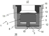
본 발명은 내부 챔버 및 폐쇄 단부 및 개방 단부를 갖는 고압 플라스틱 베젤(16)과 상기 고압 베젤의 개방단부에 장착되고 밸브를 가지는 압력 제어장치를 포함하는 유체 분배 베젤(17) 내의 일정한 미리 결정된 초과 압력을 유지하도록 제공되는 압력 제어 시스템에 관한 것으로, 상기 밸브에 의해 제어되는 상기 내부 챔버로부터 외부로 통로(11)가 제공되고, 넓은 원통형 돌출 스탬(3)을 가지는 피스톤(2)이 가이드 부재(5)에 제공되고, 상기 가이드 부재(5)와 피스톤(2) 사이에는 고압보다 작은 기준 압력의 가스가 있는 챔버(8)가 봉입되고, 상기 고압 베젤(16)은 스템(3)의 직경보다 작은 직경의 중심 보어(10)를 갖는 클로저(9)에 의해 폐쇄되고, 돌출 스템(3)으로부터 이격된 피스톤 단부는 유체 분배 컨테이너(17) 내의 유체에 의해 가압된다.The present invention relates to a fluid dispensing bezel comprising a high pressure plastic bezel (16) having an inner chamber and a closed end and an open end and a pressure control device mounted to the open end of the high pressure bezel and having a valve, Wherein a passage (11) is provided externally from said inner chamber controlled by said valve and a piston (2) having a wide cylindrical protruding stem (3) is provided on a guide member (5) , And a chamber (8) filled with a gas having a reference pressure smaller than a high pressure is sealed between the guide member (5) and the piston (2), and the high pressure bezel (16) And the piston end spaced from the protruding stem 3 is pressurized by the fluid in the fluid dispensing container 17. The fluid dispensing container 17 has a central bore 10,
Description
본 발명은 일정한 미리 결정된 초과 압력을 유지하도록 제공된 압력 제어 시스템에 관한 것이다.The present invention relates to a pressure control system provided to maintain a predetermined predetermined excess pressure.
이러한 압력 제어 시스템은 WO-A-2005/082744에 기술되어 있으며, 여기서 고압 베젤은 테이퍼진 넥 부분과 플랜지를 가지고 실질적으로 원통형이며, 그 위에 계단형 펀넬을 갖는 링 형상 삽입물 또는 클로저가 장착된다. 본 명세서의 압력 제어 장치는 폐쇄 단부와 개방 단부를 갖는 컵형 실린더에 의해 링형 클로저 내에 제공되며, 하향 돌출 스템과 넓은 원통형 단부가 있는 피스톤이 이동 가능하게 장착된다. 피스톤은 컵형 실린더의 내벽에 O 링에 의해 밀봉되고 왕복 운동이 가능하다. 계단형 깔때기의 개방 단부에서 O 링이 링 실린더에 의해 끼워지는 반면, 스템 및 O 링의 넓은 원통형 부분은 가압된 가스 즉, 피스톤 및 폐쇄 단부를 갖는 컵형 실린더에 의해 형성된 챔버 내에서의 공기의 압력에 의해 왕복 운동으로 움직이는 밸브를 제공한다.This pressure control system is described in WO-A-2005/082744, where the high-pressure bezel is substantially cylindrical with a tapered neck portion and flange, and on which a ring-shaped insert or closure with a stepped funnel is mounted. The pressure control device of the present disclosure is provided in a ring-shaped closure by a cup-shaped cylinder having a closed end and an open end, and a piston with a downwardly projecting stem and a wide cylindrical end is movably mounted. The piston is sealed by an O-ring on the inner wall of the cup-shaped cylinder and is reciprocatingly movable. While the O-ring at the open end of the stepped funnel is sandwiched by the ring cylinder, the wider cylindrical portion of the stem and the O-ring is pressurized, i.e., the pressure of the air in the chamber formed by the cup-shaped cylinder with the piston and closed end To move in a reciprocating motion.
피스톤을 컵형 실린더에 장착할 때 O 링의 외벽이 손상을 입거나 파손되지 않는 것이 중요하다. 가압 가스 또는 공기가 표준 압력을 점차적으로 벗어나 감소될 수 있기 때문에 이미 매우 작은 절개는 압력 제어 장치의 수명에 영향을 미친다. 스템의 넓은 원통형 부분을 가진 밸브를 제공하는 끼워진 O-링에서 유사한 문제가 발생한다. 사용 중 피스톤과 스템은 1mm 미만의 왕복 운동을 하지만, 압력 제어 시스템의 수명에 영향을 미치는 마모가 적다.It is important that the outer wall of the O-ring is not damaged or broken when the piston is mounted on the cup-shaped cylinder. The already very small incision affects the service life of the pressure control device, since the pressurized gas or air can be reduced gradually out of the standard pressure. A similar problem arises in a fitted O-ring that provides a valve with a wide cylindrical portion of the stem. During use, the piston and stem will undergo a reciprocating motion of less than 1 mm, but wear less, which affects the life of the pressure control system.
본 발명의 목적은 간단한 구조로 용이하게 조립 및 가압될 수 있는 고압 베젤를 갖는 압력 제어 시스템을 제공하는 것이다. 본 발명의 다른 목적은 부품의 마모를 무시할 수 있는 압력 제어 장치를 제공하는 것이다. 본 발명의 이러한 목적은 청구항 1의 특징을 갖는 압력 제어 시스템에 의해 달성된다.It is an object of the present invention to provide a pressure control system having a high pressure bezel that can be easily assembled and pressed with a simple structure. Another object of the present invention is to provide a pressure control device which can ignore wear of parts. This object of the invention is achieved by a pressure control system having the features of
본 발명의 실시예에 따르면, 유체 분배 용기에서 일정한 소정의 초과 압력을 유지하기위한 압력 제어 시스템은 내부 챔버와 폐쇄 단부 및 개방 단부를 갖는 고압 플라스틱 베젤과, 고압 베젤의 개방 단부 상에 장착되고 밸브를 가지는 압력 제어 장치를 포함한다. 반면, 통로는 밸브에 의해 제어되는 내부 챔버로부터 외부로 제공된다. 돌출하는 스템을 갖는 피스톤이 가이드 부재에 제공되는 반면, 가이드 부재와 피스톤 사이에는 고압보다 작은 기준 압력을 갖는 챔버가 둘러싸여 진다. 고압 베젤은 스템 직경보다 작은 직경의 중심 보어를 갖는 클로저에 의해 폐쇄되고, 돌출하는 스템으로부터 이격된 피스톤 단부는 유체 분배 용기 내의 유체에 의해 가압된다. 스템의 직경에 비해 중앙 보어의 직경이 작기 때문에 스탬은 중앙 보어를 밀봉할 수 있다. 유체 용기 내의 유체로부터의 압력은 스템을 중앙 보어에 밀어 넣음으로써 고압 베젤이 기밀 폐쇄되도록 한다.According to an embodiment of the present invention, a pressure control system for maintaining a certain predetermined excess pressure in a fluid distribution vessel comprises a high pressure plastic bezel having an inner chamber, a closed end and an open end, And a pressure control device. On the other hand, the passage is provided externally from the inner chamber controlled by the valve. A piston having a protruding stem is provided in the guide member, while a chamber having a reference pressure smaller than the high pressure is enclosed between the guide member and the piston. The high pressure bezel is closed by a closure having a central bore with a diameter smaller than the stem diameter and the piston end spaced from the protruding stem is pressed by fluid in the fluid distribution vessel. Since the diameter of the central bore is smaller than the diameter of the stem, the stem can seal the central bore. The pressure from the fluid in the fluid container pushes the stem into the central bore so that the high-pressure bezel is hermetically closed.
압력 제어 시스템의 실시예에 따르면, 피스톤은 탄성 수단에 의해 고압 베젤의 클로저를 향해 가압된다. 탄성 수단은 가이드 부재의 외측 림에 고정되는 제 2 탄성 디스크이다. 탄성 수단에 의해 스템으로부터 중앙 보어에 대한 압력이 증가될 수 있다.According to an embodiment of the pressure control system, the piston is urged by the resilient means towards the closure of the high pressure bezel. The elastic means is a second elastic disk fixed to the outer rim of the guide member. The pressure from the stem to the central bore can be increased by the resilient means.
압력 제어 시스템의 다른 실시예에 따르면, 클로저의 보어는 안내 부재와 클로저 사이에 고정되는 제 1 탄성 디스크에 의해 덮인다. 중심 보어는 제 1 탄성 디스크에 의해 기밀 폐쇄된다.According to another embodiment of the pressure control system, the bore of the closure is covered by a first resilient disc fixed between the guide member and the closure. The central bore is hermetically closed by the first resilient disc.
추가의 장점은 하기 설명에 따른다.Additional advantages follow the description below.
하기에, 본 발명은 첨부된 도면을 참조하여 예시로 보다 상세하게 설명된다.BRIEF DESCRIPTION OF THE DRAWINGS In the following, the invention is explained in more detail by way of example with reference to the accompanying drawings.
도 1은 피스톤 및 밸브의 개방 상태에서 피스톤을 안내하는 가이드 부재를 갖는 압력 제어 시스템, 및
도 2는 밸브가 폐쇄 상태에 있는 도 1의 압력 제어 시스템.1 shows a pressure control system having a guide member for guiding the piston in the open state of the piston and valve,
Figure 2 shows the pressure control system of Figure < RTI ID = 0.0 > 1 < / RTI >
도 1은 넓은 원통형 부분(4) 및 아래로 돌출된 스템(3)을 갖는 피스톤(2)을 갖는 압력 제어 시스템(1)을 도시하며, 피스톤은 안내 부재(5)에서 안내된다. 안내 부재(5)는 제 1 중심 보어(7)를 갖는 원형 디스크(6)가 있는 원통형 실린더 형태를 가진다. 스템(3)의 직경은 제 1 중앙 보어(7)의 직경보다 약간 작기 때문에, 스템(3)은 중심 보어(7)에서 왕복 운동하는 방식으로 다소 기밀상태로 움직일 수 있다. 피스톤(2)의 넓은 원통형 부분(4)의 외벽은 가이드 부재(5)의 내벽을 따라 다소 기밀상태로 이동 가능하다. 피스톤의 바닥과 가이드 부재(5)의 대향하는 내부 바닥 벽 사이에는 기준 압력 챔버(8)가 제공된다. 가이드 부재(5)는 스템(3)에 의해 제 2 보어(10)가 폐쇄될 수 있도록 돌출 스템(3)의 직경보다 작은 직경을 갖는 제 2 중심 보어(10)를 갖는 컵형 클로저(9)에 끼워져서 장착된다. 도 1 및 도 2에서 알 수 있는 바와 같이, 스템(3)의 단부는 둥글게 되고 보어(10)의 입구는 스템(3)의 둥근 형태에 상응하는 원추형이다. 안내 부재(5)와 클로저(9) 사이에는 가압된 가스 또는 공기가 클로저(9)의 하부에서 상부로 흐를 수 있도록 채널 또는 통로(11)가 제공된다. 채널(11)은 약 2mm 미만의 작은 횡단면을 갖는다. 탄성 디스크(12)는 가이드 부재(5)의 원형 디스크(6)와 클로저(9)의 바닥 부분(14) 사이에 고정된다. 따라서, 상기 제 1 탄성 디스크 또는 개스킷(12)은 가이드 부재(5)의 하부 벽 및 클로저(9)의 내벽에 의해 클램핑된다. 가이드 부재(5)의 상부에는 제 2 탄성 디스크 또는 개스킷(13)이 클로저(9) 내에 압입 끼워 맞춤되어 장착된 링 형상 스톱 부재(15)를 포함한다.Figure 1 shows a
따라서, 피스톤(2)은 탄성 수단으로 피스톤(2)을 휴지 위치로 가압하는 제 1 개스킷(12) 및 제 2 개스킷(13)에 의해 둘러싸인다. 클로저(9)는 참조 번호 16으로 표시된 고압 베젤 상에 장착된다. 링 형상의 스톱 부재(15)는 참조 번호 17로 표시된 유체 분배 용기 내로 개방된다.Thus, the
도 2에서, 돌출 스템(3), 제 1 개스킷(12) 및 클로저(9)의 제 2 중앙 보어(10)에 의해 제공되는 밸브가 폐쇄되는 압력 제어 시스템(1)이 도시된다. 상기 폐쇄 상태에서, 유체 분배 용기(17) 및 기준 압력 챔버(8) 내의 압력은 본질적으로 동일하다. 유체 분배 용기(17)의 압력이 하강하면 유체가 용기(17)의 푸시-버튼(미도시)을 통해 토출되기 때문에 피스톤(2)이 상방으로 가압되어 밸브가 개방되므로 용기(17)내의 압력과 기준 압력 챔버(7)의 압력이 더해지고 보어(10)를 향한 스탬(3)의 압력이 다시 동일해져 상기 상태하에서 밸브가 폐쇄될 때까지 고압 가스는 통로(11)를 통하여 용기(17)내로 흐르게 된다.2 a
스템(3)의 길이는 기준 압력 챔버(8)의 부피를 규정한다. 스템(3)의 길이가 확장되면, 피스톤(2)의 넓은 원통형 부분(4)의 두께가 따라서 감소한다. 전술한 압력 제어 시스템(1)의 모든 부분은 플라스틱으로 만들어진다. 피스톤(2)은 일반적으로 고체이지만, 피스톤의 원통형 부분(4)은 중공일 수 있다. 또한, 압력 제어 시스템(1)은 일반적으로 원통형이지만 사각 원통형일 수도 있다. 다른 원통형도 사용할 수 있다.The length of the stem (3) defines the volume of the reference pressure chamber (8). As the length of the stem 3 expands, the thickness of the wide
압력 제어 시스템(1)의 부품은 대기압하에 장착되어 시스템의 휴지 상태(도 1)에서 기준 챔버(8)의 압력은 약 1 bar이다. 밸브가 폐쇄되면(도 2), 즉, 제 1 개스킷(12)을 갖는 스템(3)이 보어(10)를 막 폐쇄할 때, 기준 챔버(8)의 압력과 스템(3)의 폐쇄 압력을 합한 압력은 유체 분배 용기내의 압력과 동일해진다. 피스톤(2)의 스템(3)이 더 길면 기준 챔버(8)의 체적이 커져, 스템(3)의 압력 차와 스트로크 사이의 비가 작아지므로, 더 세밀한 압력 제어가 가능하다.The components of the
당업자에게는 제 1 및 제 2 가스켓(12, 13)이 전술한 바와 같이 압력 제어 시스템(1)의 기능을 위해 절대적으로 필요하지 않다는 것이 더 명백할 것이다. 피스톤의 넓은 원통형 부분(4)의 외부 벽이 충분히 크다면, 피스톤은 가이드 부재(5)의 내벽에 대해 기밀로 밀봉되어, 스템(3)의 외측 단부는 이미 자체적으로 폐쇄 위치에 있는 경우, 보어(10)를 충분히 폐쇄한다. 스템(3)은 또한 중앙 보어(7)에서 기밀 형태로 움직일 수 있어야 한다.It will be clear to those skilled in the art that the first and
Claims (4)
Applications Claiming Priority (3)
| Application Number | Priority Date | Filing Date | Title |
|---|---|---|---|
| EP15152767 | 2015-01-27 | ||
| EPEP15152767.8 | 2015-01-27 | ||
| PCT/EP2016/051572 WO2016120269A1 (en) | 2015-01-27 | 2016-01-26 | Pressure control system |
Publications (1)
| Publication Number | Publication Date |
|---|---|
| KR20170130363A true KR20170130363A (en) | 2017-11-28 |
Family
ID=52423609
Family Applications (1)
| Application Number | Title | Priority Date | Filing Date |
|---|---|---|---|
| KR1020177022325A KR20170130363A (en) | 2015-01-27 | 2016-01-26 | Pressure control system |
Country Status (10)
| Country | Link |
|---|---|
| US (1) | US10543974B2 (en) |
| EP (1) | EP3250476B1 (en) |
| KR (1) | KR20170130363A (en) |
| CN (1) | CN107207149B (en) |
| BR (1) | BR112017015931A2 (en) |
| CA (1) | CA2974469C (en) |
| DK (1) | DK3250476T3 (en) |
| MX (1) | MX2017009729A (en) |
| PL (1) | PL3250476T3 (en) |
| WO (1) | WO2016120269A1 (en) |
Families Citing this family (2)
| Publication number | Priority date | Publication date | Assignee | Title |
|---|---|---|---|---|
| WO2020092943A1 (en) | 2018-11-02 | 2020-05-07 | Dlhbowles, Inc. | Aerosol nozzle assembly and nozzle cup member for spraying viscous newtonian fluids |
| WO2020104046A1 (en) | 2018-11-23 | 2020-05-28 | Aluair Gmbh | Dispenser container, dispenser and method for manufacturing a dispenser container |
Family Cites Families (7)
| Publication number | Priority date | Publication date | Assignee | Title |
|---|---|---|---|---|
| EP0349053B1 (en) * | 1988-06-29 | 1992-06-17 | Jaico C.V. Cooperatieve Vennootschap | Pressure capsule for spray can, and spray can which utilizes such a capsule |
| BE1003682A3 (en) * | 1990-02-09 | 1992-05-19 | Jaico Cv | Drukkapsule for aerosol aerosol and those applying such drukkapsule. |
| US5110014A (en) * | 1990-11-07 | 1992-05-05 | Doundoulakis George J | Bi-stable pressure maintaining gas containers |
| NL1012754C2 (en) * | 1999-07-30 | 2001-02-01 | Presstech N V | Pressure control device. |
| NL1022456C2 (en) * | 2003-01-21 | 2004-07-22 | Packaging Tech Holding Sa | Pressure package system for applying a working pressure to a fluid contained in a pressure package. |
| CN100519363C (en) * | 2004-01-30 | 2009-07-29 | 智能包装系统集团股份有限公司 | Pressure control device |
| JP2005230299A (en) * | 2004-02-20 | 2005-09-02 | Katsutoshi Masuda | Fluid storage vessel |
-
2016
- 2016-01-26 WO PCT/EP2016/051572 patent/WO2016120269A1/en active Application Filing
- 2016-01-26 KR KR1020177022325A patent/KR20170130363A/en not_active Application Discontinuation
- 2016-01-26 CA CA2974469A patent/CA2974469C/en active Active
- 2016-01-26 MX MX2017009729A patent/MX2017009729A/en unknown
- 2016-01-26 PL PL16703076T patent/PL3250476T3/en unknown
- 2016-01-26 EP EP16703076.6A patent/EP3250476B1/en active Active
- 2016-01-26 US US15/546,356 patent/US10543974B2/en active Active
- 2016-01-26 CN CN201680007291.4A patent/CN107207149B/en not_active Expired - Fee Related
- 2016-01-26 DK DK16703076.6T patent/DK3250476T3/en active
- 2016-01-26 BR BR112017015931A patent/BR112017015931A2/en active Search and Examination
Also Published As
| Publication number | Publication date |
|---|---|
| BR112017015931A2 (en) | 2018-03-27 |
| CN107207149A (en) | 2017-09-26 |
| US10543974B2 (en) | 2020-01-28 |
| WO2016120269A1 (en) | 2016-08-04 |
| US20170327301A1 (en) | 2017-11-16 |
| CA2974469A1 (en) | 2016-08-04 |
| CA2974469C (en) | 2019-04-02 |
| EP3250476A1 (en) | 2017-12-06 |
| PL3250476T3 (en) | 2019-04-30 |
| CN107207149B (en) | 2019-05-31 |
| US20180148248A9 (en) | 2018-05-31 |
| DK3250476T3 (en) | 2018-11-19 |
| EP3250476B1 (en) | 2018-08-29 |
| MX2017009729A (en) | 2018-08-01 |
Similar Documents
| Publication | Publication Date | Title |
|---|---|---|
| US9310812B2 (en) | Multi-stage pressure regulator and method for fluid pressure regulation | |
| KR102128801B1 (en) | Foam discharge device | |
| EP1872859B1 (en) | Simplified pump for dispensing fluid substances withdrawn from a container | |
| JP6705877B2 (en) | Escape valve for watch | |
| MX2019009296A (en) | Keg closure with integrated venting system. | |
| CN107763260B (en) | Pressure relief valve and air conditioning system | |
| KR20170130363A (en) | Pressure control system | |
| KR20170092219A (en) | Relief valve | |
| CA2781731C (en) | Pressure regulated flow valve with gas-piston | |
| US20160091097A1 (en) | Pressure reducing valve | |
| CA2646087A1 (en) | Valve for a compressed gas container | |
| JP5288425B1 (en) | Filling pump and filling device | |
| RU2290682C1 (en) | Gas reducer | |
| EP0484616B1 (en) | Manually operated pump device for dispensing fluids | |
| JP7236960B2 (en) | discharge container | |
| KR102491065B1 (en) | Pump container | |
| CN112303317B (en) | Pilot-operated electromagnetic valve | |
| KR200295744Y1 (en) | Pumping device of liquid vessel | |
| JP2011033074A (en) | Diaphragm valve | |
| KR101518846B1 (en) | Valve for Portable High Pressure Gas Tank | |
| US831739A (en) | Pressure-regulator. | |
| CN111609188A (en) | Pressure reducing valve | |
| CN114643559A (en) | Pneumatic knocking device and actuating method thereof | |
| JPS60220202A (en) | Pressure accumulator | |
| GB2561189A8 (en) | Piezo controlled inlet valve |
Legal Events
| Date | Code | Title | Description |
|---|---|---|---|
| A201 | Request for examination | ||
| E902 | Notification of reason for refusal | ||
| E601 | Decision to refuse application |