KR20170127689A - Multi-type lifting scaffold - Google Patents
Multi-type lifting scaffold Download PDFInfo
- Publication number
- KR20170127689A KR20170127689A KR1020160058077A KR20160058077A KR20170127689A KR 20170127689 A KR20170127689 A KR 20170127689A KR 1020160058077 A KR1020160058077 A KR 1020160058077A KR 20160058077 A KR20160058077 A KR 20160058077A KR 20170127689 A KR20170127689 A KR 20170127689A
- Authority
- KR
- South Korea
- Prior art keywords
- fixed
- elevating
- footrest
- latch
- wire rope
- Prior art date
Links
Images


Classifications
-
- B—PERFORMING OPERATIONS; TRANSPORTING
- B63—SHIPS OR OTHER WATERBORNE VESSELS; RELATED EQUIPMENT
- B63C—LAUNCHING, HAULING-OUT, OR DRY-DOCKING OF VESSELS; LIFE-SAVING IN WATER; EQUIPMENT FOR DWELLING OR WORKING UNDER WATER; MEANS FOR SALVAGING OR SEARCHING FOR UNDERWATER OBJECTS
- B63C5/00—Equipment usable both on slipways and in dry docks
- B63C5/02—Stagings; Scaffolding; Shores or struts
-
- B63B9/00—
-
- B63B9/06—
-
- E—FIXED CONSTRUCTIONS
- E04—BUILDING
- E04G—SCAFFOLDING; FORMS; SHUTTERING; BUILDING IMPLEMENTS OR AIDS, OR THEIR USE; HANDLING BUILDING MATERIALS ON THE SITE; REPAIRING, BREAKING-UP OR OTHER WORK ON EXISTING BUILDINGS
- E04G3/00—Scaffolds essentially supported by building constructions, e.g. adjustable in height
- E04G3/28—Mobile scaffolds; Scaffolds with mobile platforms
- E04G3/30—Mobile scaffolds; Scaffolds with mobile platforms suspended by flexible supporting elements, e.g. cables
- E04G3/305—Mobile scaffolds; Scaffolds with mobile platforms suspended by flexible supporting elements, e.g. cables specially adapted for tanks, silos or similar vessels
-
- E—FIXED CONSTRUCTIONS
- E04—BUILDING
- E04G—SCAFFOLDING; FORMS; SHUTTERING; BUILDING IMPLEMENTS OR AIDS, OR THEIR USE; HANDLING BUILDING MATERIALS ON THE SITE; REPAIRING, BREAKING-UP OR OTHER WORK ON EXISTING BUILDINGS
- E04G3/00—Scaffolds essentially supported by building constructions, e.g. adjustable in height
- E04G3/28—Mobile scaffolds; Scaffolds with mobile platforms
- E04G3/30—Mobile scaffolds; Scaffolds with mobile platforms suspended by flexible supporting elements, e.g. cables
- E04G3/32—Hoisting devices; Safety devices
-
- E—FIXED CONSTRUCTIONS
- E04—BUILDING
- E04G—SCAFFOLDING; FORMS; SHUTTERING; BUILDING IMPLEMENTS OR AIDS, OR THEIR USE; HANDLING BUILDING MATERIALS ON THE SITE; REPAIRING, BREAKING-UP OR OTHER WORK ON EXISTING BUILDINGS
- E04G5/00—Component parts or accessories for scaffolds
- E04G5/08—Scaffold boards or planks
-
- B—PERFORMING OPERATIONS; TRANSPORTING
- B63—SHIPS OR OTHER WATERBORNE VESSELS; RELATED EQUIPMENT
- B63C—LAUNCHING, HAULING-OUT, OR DRY-DOCKING OF VESSELS; LIFE-SAVING IN WATER; EQUIPMENT FOR DWELLING OR WORKING UNDER WATER; MEANS FOR SALVAGING OR SEARCHING FOR UNDERWATER OBJECTS
- B63C5/00—Equipment usable both on slipways and in dry docks
- B63C5/02—Stagings; Scaffolding; Shores or struts
- B63C2005/025—Stagings, or scaffolding, i.e. constructions providing temporary working platforms on slipways, in building or repair docks, or inside hulls
- B63C2005/027—Stages, platforms, or seats suspended adjacent ship hulls on cables, chains, or the like, e.g. boatswain's chairs
Abstract
Description
본 발명은 다단 승강형 족장에 관한 것으로, 더 상세하게는 복수 개로 마련된 발판을 전동방식에 의해 한 번에 여러 단으로 펼치고 접어서 사용할 수 있도록 하면서 흔들림을 최소화하고 높은 안전성을 가질 수 있도록 한 다단 승강형 족장에 관한 것이다. The present invention relates to a multi-stage elevating chieftain, and more particularly, to a multi-stage elevating chieftain which can be folded and folded at a plurality of stages at one time by a motorized method to minimize shaking, It is about a patriarch.
최근에 들어 대형 선박을 비롯한 각종 해양 구조물은 그에 해당되는 각종 해양 블록을 별도로 각각 제작한 후 용접 등을 통하여 기본 형태로 완성한 다음 필요로 하는 제반 설비를 차례로 설치하는 방식으로 건조하고 있다. Recently, various marine structures including large vessels have been manufactured by separately manufacturing various marine blocks corresponding to the marine structures, completing the marine blocks in a basic form through welding, and then installing the necessary facilities in sequence.
이렇게, 각종 해양 블록을 제조하는 과정에서는 작업자들이 올라가 작업할 수 있는 족장을 설치하여 원활한 작업이 이루어질 수 있도록 사용된다. In this way, in the process of manufacturing various marine blocks, it is used so that the work can be smoothly installed by installing the chiefs who can work up.
족장을 설치하는 종래의 통상적인 방법은 먼저 복수의 지주를 소정 간격으로 위치시킨 후 각각의 강관과 강관 클램프 등을 사용하여 격자 형태의 구조물로 제작한 다음 발판을 얹고, 상기 발판을 강관에 반선으로 엮어서 고정하는 방식으로 설치하였다. Conventionally, a conventional method of installing a patriot is to construct a lattice-like structure by placing a plurality of pillars at predetermined intervals, then using steel pipes and steel tube clamps, and then laying a foot plate, It was installed by weaving and fixing.
그러나 이러한 방식은 설치 및 해체시 작업자의 수작업으로 인해 작업이 진행됨에 따라 과다한 작업시간이 소요됨과 아울러 그로 인한 경제적인 손실이 큰 단점을 가진다. However, this method has a disadvantage in that it takes a long time to work as the work is progressed due to the manual operation of the operator during installation and dismantling, and in addition, the economic loss is large.
상기와 같이 족장과 관련된 종래 선행기술에는 대한민국 등록실용신안 제20-0472461호에서와 같이 소둔철사를 사용하지 않더라도 족장판을 보다 간편하게 설치 또는 철거할 수 있어 작업 효율을 향상시킬 수 있는 선박용 작업대와 같은 기술이 제안된 바 있다. Conventional prior art related to the chieftain such as that of Korean Registered Utility Model No. 20-0472461 can easily install or dismount the chieftain board even without using annealing wire, Technology has been proposed.
또한, 대한민국 공개실용신안 제20-2014-0004021호에 게시된 바와 같이 제1 블록과 제2 블록의 연결 시 보조 족장이 제1 족장과 제2 블록의 제2 족장 사이의 간격을 연결할 수 있도록 하여, 별도의 족장을 설치하는 작업을 생략할 수 있도록 하는 블록 조립용 족장 구조와 같은 기술도 제안된 바 있다. Also, as disclosed in Korean Utility Model No. 20-2014-0004021, when the first block and the second block are connected, the auxiliary patriarch can connect the gap between the first patriarch and the second patriarch of the second block , And a chieftain structure for block assembly, which eliminates the task of installing a separate chieftain, has been proposed.
그러나 상기한 족장은 1단으로만 마련됨으로써, 작업하고자 하는 위치가 높을 경우 설치하기가 상당히 어렵고 불편한 단점을 가진다. However, since the above-described chieftain is provided only in one stage, it is disadvantageous in that it is considerably difficult and inconvenient when the position to be worked is high.
이러한 문제점을 해결하기 위하여, 종래에도 대한민국 공개실용신안 제20-1998-0006997호(이하 '선행기술문헌 1'이라 한다)에 게시된 바와 같이 작업부를 상승과 하강시키는 X자형 승강 레일을 포함하는 작업대와 같은 기술도 제안된 바 있다. In order to solve such a problem, as disclosed in Korean Utility Model No. 20-1998-0006997 (hereinafter referred to as "
또한, 대한민국 공개특허 제10-2013-0115505호(이하 '선행기술문헌 2'라 한다)에 게시된 바와 같이 체결구에 가로 안전대를 올려놓은 후 손으로 잡고 있는 등의 별다를 조치가 없어도 가로 안전대가 떨어져 내리지 않고, 체결구가 가로 안전대를 확실하게 지지할 수 있도록 체결구의 구성 요소인 고정간의 단부가 상향으로 절곡된 구조를 가지는 선박 건조용 안전 난간과 같은 기술도 제안된 바 있다. In addition, as disclosed in Korean Patent Laid-Open No. 10-2013-0115505 (hereinafter referred to as "Prior Art Document 2"), even if there is no different measure such as holding a horizontal safety table on a fastener and holding it by hand, There has been proposed a technique such as a safety guardrail for a ship having a structure in which an end portion of a fastening member, which is a component of a fastening member, is bent upward so that the fastening member can reliably support the transverse restraint.
또, 대한민국 등록특허 제10-1516203호(이하 '선행기술문헌 3'이라 한다)게 게시된 바와 같이 간편하면서도 효율적인 구조를 통해 조립 작업을 가이드 할 수 있어 종전과 달리 적은 인원으로도 안전하게 구축할 수 있는 선박 화물창용 시스템 족장과 같은 기술도 제안된 바 있다. In addition, as disclosed in Korean Patent No. 10-1516203 (hereinafter referred to as "Prior Art Document 3"), it is possible to guide assembly work through a simple and efficient structure, Techniques such as the ship chief system for ship cargo windows have also been proposed.
그러나 선행기술문헌 1은 X자형 승강 레일의 길이만큼만 승강 됨에 따라 해양 블록 등과 같이 높이가 높은 구조물에는 적합하지 않은 단점을 가진다. However, the
선행기술문헌 2 내지 3은 발명의 배경이 되는 기술에서 언급한 바와 같이 수개의 지주 또는 파이프를 작업자의 수작업에 의해 직접 설치해야 함으로 인한 문제점을 그대로 가진다. The prior art documents 2 and 3 have the problems caused by manually installing several columns or pipes manually by the operator as mentioned in the background of the invention.
상기와 같은 종래의 제반 문제점을 해결하기 위한 본 발명의 주된 해결과제는 복수 개로 마련된 발판을 전동방식에 의해 한 번에 여러 단으로 펼치고 접어서 사용할 수 있도록 하면서 흔들림을 최소화하고 높은 안전성을 가질 수 있도록 한 다단 승강형 족장을 제공하는 데 있다. The main object of the present invention is to provide a footrest which can be folded and folded at a plurality of stages at one time by a motorized method to minimize shaking, To provide a multi-stage elevated chieftain.
본 발명의 해결하기 위한 다른 해결과제는 작업자의 추락 사고를 방지할 수 있도록 하는 데 있다. Another problem to be solved by the present invention is to prevent a fall of an operator.
상기와 같은 기술적 과제를 해결하기 위한 본 발명의 해결수단은 작업대상물의 상부에 고정되는 고정 발판; 상기 고정 발판의 상면 양측에 각각의 승강 와이어 로프가 권취된 권취 휠을 포함하여 마련되는 각각의 구동모터; 상기 고정 발판의 하부에 상기 각 승강 와이어 로프가 관통되어 순차적으로 승강 가능하도록 연결되는 복수의 승강 발판; 및 상기 고정 발판 및 각 승강 발판 사이의 각 모서리에는 작업공간의 높이를 확정하기 위해 연결 고정되는 고정 와이어 로프;를 포함한다. According to an aspect of the present invention, there is provided a method of manufacturing a workpiece, A plurality of drive motors provided on both sides of the upper surface of the fixed footrest, each of the drive motors including a take-up wheel around which a respective hoisting wire rope is wound; A plurality of elevating foots connected to the lower portion of the fixed footrest so that the elevating wire ropes pass through the elevating wire ropes in a sequential manner; And a fixed wire rope fixed at each corner between the fixed footrest and each elevating footrest to fix the height of the work space.
상기 고정 발판 및 각 승강 발판 사이에는 하강 후 흔들림을 방지하기 위한 지지수단을 더 포함한다. Further, a supporting means for preventing shaking after descending is further provided between the fixed footrest and each elevating footrest.
상기 지지수단은 상기 고정 발판 및 각 승강 발판의 각 프레임 상면의 모서리에 구비되는 각각의 러그, 상기 고정 발판의 프레임과 승강 발판의 프레임 밑면에 상단이 회전 가능하게 결합되며 하단은 상기 각 러그와 맞닿아 결합구에 의해 탈착되도록 절첩 가능하게 마련되는 각각의 지지대를 포함한다. Wherein the supporting means comprises: an upper end rotatably coupled to a lower surface of a frame of the fixed foot and a frame of the elevating foot, and a lower end rotatably coupled to the lower end of the frame, And each of the supports is provided so as to be foldable so as to be detachable by the coupling means.
상기 결합구는 러그와 지지대를 일측에서 관통하는 고정래치, 상기 관통된 고정래치의 타측에 체결되는 래치 잠금부재를 포함한다. The coupling member includes a fixing latch that penetrates the lug and the supporting member from one side, and a latch lock member that is fastened to the other side of the through fixing latch.
상기 래치 잠금부재는 관통된 고정래치의 일측에 회전 가능하게 구비되는 회동편, 상기 회동편의 타측은 고정 핀에 의해 고정래치의 타측으로 고정되게 마련된다. The latch lock member is a pivotal piece rotatably provided on one side of a through-hole fixed latch, and the other side of the pivotal latch is fixed to the other side of the fixed latch by a fixing pin.
상기 고정 발판 프레임과 각 승강 발판 프레임의 일측면에는 승강에 따른 절첩 가능하게 마련되는 각각의 안전부재를 포함한다. Each of the fixed foot frame and each of the elevating foot frame includes a safety member provided on one side of the elevating frame so as to be foldable along the elevation.
상기 안전부재는 각 프레임의 대응되는 위치에 마련되는 각각 가이드 레일, 상기 각 가이드 레일에 각 끝단이 삽입되어 슬라이딩 가능하게 구비되는 각각의 안전 바를 포함하되, 상기 안전 바는 X자 형태로 마련된다. The safety member includes guide rails provided at corresponding positions of the frames, and safety bars slidably inserted into the guide rails, wherein the safety bars are formed in an X shape.
본 발명은 복수 개로 마련된 발판을 전동방식에 의해 한 번에 여러 단으로 펼치고 접어서 사용할 수 있도록 하면서 흔들림을 최소화하고 높은 안전성을 가질 수 있도록 함으로써, 높은 높이를 가지는 작업대상물에서도 번거롭거나 불편함 없이 간편하게 설치 및 해체할 수 있는 효과와 함께 작업자가 안전하면서 신속하게 작업을 수행할 수 있는 효과도 가진다. The present invention minimizes wobbling and ensures high safety by folding and folding a plurality of foot plates provided at a plurality of stages at one time by a motorized method, so that even a workpiece having a high height can be easily and easily handled without inconvenience Installation and disassembly of the apparatus, and also has an effect that the operator can perform the work safely and quickly.
또한, 작업자의 추락 사고를 방지할 수 있도록 함으로써, 작업자에게는 위험요소를 극소화한 상태로 안전하게 작업을 행할 수 있는 효과도 가진다. In addition, by preventing the operator from falling down, it is possible to safely perform the work with the risk factors minimized for the worker.
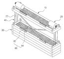
도 1은 본 발명을 설명하기 위한 접혀진 상태의 사시도,
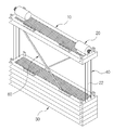
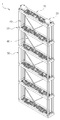
도 2는 도 1에 따른 펼쳐진 상태의 사시도,
도 3a 내지 도 3g는 본 발명이 순차적으로 펼쳐지는 과정을 설명하기 위한 순서도이다. 1 is a perspective view of a folded state for explaining the present invention,
Fig. 2 is a perspective view in an unfolded state according to Fig. 1,
FIGS. 3A to 3G are flowcharts for explaining a process in which the present invention is sequentially deployed.
이하, 본 발명의 바람직한 실시 예를 첨부된 도면을 참고하여 좀 더 상세하게 설명하면 다음과 같으며, 본 발명이 실시 예에 의해 제한되거나 한정되는 것은 아니다. Hereinafter, preferred embodiments of the present invention will be described in more detail with reference to the accompanying drawings. The present invention is not limited to the embodiments.
도 1은 본 발명을 설명하기 위한 접혀진 상태의 사시도이며, 도 2는 도 1에 따른 펼쳐진 상태의 사시도이고, 도 3a 내지 도 3g는 본 발명이 순차적으로 펼쳐지는 과정을 설명하기 위한 순서도이다. FIG. 1 is a perspective view of a folded state for explaining the present invention, FIG. 2 is a perspective view of an expanded state according to FIG. 1, and FIGS. 3a to 3g are flowcharts for explaining a process of sequentially expanding the present invention.
도시된 바와 같이 각종 해양 구조물을 건조하기 위해 제작되는 높은 높이를 가지는 해양 블록 등을 제작시 사용되는 다단 승강형 족장(1)을 제시한다. As shown in the figure, a multi-stage elevated chieftain (1) for use in manufacturing a marine block having a high height, which is manufactured to dry various marine structures, is presented.
본 발명은 복수 개로 마련된 발판을 전동방식에 의해 한 번에 여러 단으로 펼치고 접어서 사용할 수 있도록 하면서 흔들림을 최소화하고 높은 안전성을 가질 수 있도록 하는 데 있다. The present invention aims at minimizing shaking and providing high safety while allowing a plurality of foot plates to be folded and folded at several stages at a time by a motorized method.
본 발명에 따른 다단 승강형 족장(1)은 해양 블록 등과 같은 작업대상물(도시하지 않음)의 상부에 크레인으로 매달거나 혹은 작업대상물의 갑판 등에 설치되는 프레임 등에 의해 일정한 위치로 공지된 방식에 의해 고정되는 고정 발판(10)과; 상기 고정 발판(10)의 상면 양측에 각각의 승강 와이어 로프(22)가 권취된 권취 휠(24)을 포함하여 마련되는 각각의 구동모터(20)와; 상기 고정 발판(10)의 하부에 상기 각 승강 와이어 로프(22)가 관통되어 순차적으로 승강 가능하도록 연결되는 복수의 승강 발판(30); 및 상기 고정 발판(10) 및 각 승강 발판(30) 사이의 각 모서리에는 작업공간의 높이를 확정하기 위해 연결 고정되는 고정 와이어 로프(40);를 포함한다. The multi-stage elevated
승강 와이어 로프(22)의 밑단은 최하부 측의 승강 발판(30)의 밑면에 공지된 방식에 의해 빠지지 않도록 고정 또는 결속 고정된다. The bottom of the
고정 발판(10)과 승강 발판(30)은 통상적인 구조로 테두리를 이루는 프레임(12)(32)과, 상기 프레임(12)(32)의 내측에 작업자가 발을 딛고 설 수 있도록 복수의 관통공이 형성된 플레이트(14)(34)로 구성된다. 이때, 고정 발판과 승강 발판은 고정 발판에 설치되는 구동모터를 제외한 동일한 구조로 형성하는 것이 바람직하다. 상기 플레이트는 통상적인 그레이팅으로 대체될 수 있다. The
그에 따라 작업대상물의 상부에 고정된 고정 발판 상의 구동모터를 구동시켜 권취 휠을 회전시킴에 따라 권취 휠의 승강 와이어 로프는 하강하게 되고, 그로 인해 고정 발판의 직하부에 위치한 승강 발판이 하강하게 된다. Accordingly, the driving motor on the fixed footrest fixed to the upper portion of the workpiece is driven to rotate the wind-up wheel, so that the hoisting wire rope of the wind-up wheel is lowered, thereby lowering the hoisting foot located immediately below the fixed footrest .
이렇게, 하강하는 승강 발판은 고정 와이어 로프에 의하여 작업공간의 높이까지 하강한 후 멈추게 된다. Thus, the descending elevating foot is lowered to the height of the working space by the fixed wire rope and then stopped.
그런 다음 승강 와이어 로프의 지속적인 하강으로 인한 풀림으로 인해 그 하부에 위치한 승강 발판들 또한 각 고정 와이어 로프에 의해 일정한 작업공간의 높이를 가지면서 순차적으로 하강하여 다단으로 펼쳐지게 된다. Then, due to the continuous descent of the hoisting wire rope, the hoisting platforms located at the lower part of the hoisting ropes descend sequentially and descend into multiple stages with the height of a certain work space by the respective fixed wire ropes.
따라서, 최상단의 고정 발판을 기점으로 구동모터의 구동에 의해 풀리는 승강 와이어 로프와 고정 와이어 로프로 인해 승강 발판이 순차적으로 다단 형태로 펼쳐짐으로써, 해양 블록 등과 같은 높은 높이에서의 작업 또한 종래와 같이 지주나 파이프 등을 연결하여 설치하는 번거롭고 불편한 단점을 해소할 수 있는 것이다. Therefore, since the elevating and lowering ropes unlocked by driving the driving motor from the uppermost fixed footrest and the fixed wire rope are sequentially unfolded in a multistage form, the operation at a high height, such as a marine block, It is possible to solve the disadvantage that it is troublesome and inconvenient to connect the pipes or the like.
아울러, 펼쳐진 승강 발판은 구동모터를 구동시켜 권취 휠로 승강 와이어 로프가 감기도록 함으로써, 최하단의 승강 발판부터 상부 측으로 상승 되면서 최종 고정 발판의 밑면으로 접혀지게 된다. 그로 인해 최소한의 부피로 보관 또한 용이하게 이루어질 수 있는 것이다. In addition, the elevated footrests are folded to the bottom of the final fixed footrest while being lifted from the lowermost footrest to the upper side by driving the driving motor to wind the lifting wire rope by the winding wheel. So that it can be easily stored in a minimum volume.
이로써, 본 발명은 해양 블록 등과 같은 높은 높이를 가지는 작업대상물의 상부에 고정 발판을 고정 시킨 후 그 고정 발판의 하부에 구비되는 복수의 승강 발판을 전동방식에 의해 승강이 이루어질 수 있도록 함으로써, 종래와 같이 족장의 설치 및 해체 작업 등과 같은 번거롭고 불편한 단점을 해소할 수 있을 뿐만 아니라 작업대상물로의 작업 또한 신속하게 이루어질 수 있는 부수적인 조건도 가진다. Thus, according to the present invention, since a fixed footrest is fixed to an upper portion of a workpiece having a high height such as a marine block, and a plurality of elevator footers provided below the fixed footrest can be raised and lowered by a motorized method, It is possible to solve the troublesome and inconvenient disadvantages such as the installation and dismantling of the chieftain, and also have the additional condition that the operation to the work object can be performed quickly.
그리고 상기 구동모터의 축에는 도시하지 않은 공지된 브레이크 블록을 마련하여 복수의 승강 발판이 고정 발판의 밑면으로 상승되어 접혀진 상태에서 더 이상 하강하지 않도록 고정할 수 있도록 한다. 또한, 상기 브레이크 블록에 의해 상기 복수의 승강 발판 전체를 하강하는 것이 아니라 필요로 하는 갯 수만큼만 하강하여 사용할 수도 있다. A known brake block (not shown) is provided on the axis of the driving motor so that a plurality of lifting feet are elevated to the bottom of the fixed feet and can be fixed so as not to descend further in a folded state. In addition, the whole of the plurality of lifting platforms may be lowered by the brake block, but may be used as many as necessary.
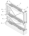
한편, 상기 고정 발판(10) 및 각 승강 발판(30) 사이에는 하강 후 흔들림을 방지하기 위한 지지수단(50)을 더 포함한다. Between the
지지수단(50)은 상기 고정 발판(10) 및 각 승강 발판(30)의 각 프레임(12)(32) 상면의 모서리에 구비되는 체결공이 형성된 각각의 러그(52)와, 상기 고정 발판(10)의 프레임(12)과 승강 발판(30)의 프레임(32) 밑면에 상단이 회전 가능하게 통상적인 힌지 또는 핀 방식에 의해 결합되며 하단은 상기 각 러그(52)와 맞닿아 결합구(55)에 의해 탈착되도록 절첩 가능하게 마련되는 각각의 지지대(54)를 포함한다. 이때, 상기 각 지지대는 프레임의 밑면으로 삽입되어 보관된 상태이며, 승강 발판이 하강함에 따라 자중에 의해 회전 가능하게 형성되는 상단을 기점으로 절첩 가능하게 마련된다. 또, 상기 힌지 또는 핀에는 통상적인 비틀림 스프링의 일단이 타단은 지지대에 고정되어 자중에 의해 하강시 어느 정도 하강되도록 함과 아울러, 다시 프레임의 밑면으로 삽입하고자 할 때 작업자의 작은 힘에 의해서도 쉽게 접혀질 수 있도록 하는 것이 바람직하다. 또, 상기 지지대의 하단에도 상기 러그에 형성된 체결공과 대응되는 결합공이 형성된다. The supporting
결합구(55)는 러그(52)와 지지대(54)를 일측에서 관통하는 통상적인 한글 자음의 디귿자 형태로 형성되는 고정래치(56)와, 상기 관통된 고정래치(56)의 타측에 체결되는 래치 잠금부재(58)를 포함한다. 이때, 상기 래치 잠금부재(58)는 관통된 고정래치(56)의 일측에 회전 가능하게 구비되는 회동편(58A)과, 상기 회동편(58A)의 타측은 고정 핀(58B)에 의해 고정래치(56)의 타측으로 고정되게 마련된다. The
그에 따라 고정 발판의 하부로 각 승강 발판이 작업공간의 높이로 하강된 상태에서 각각의 지지대를 회전시키면서 하단이 러그와 맞닿게 위치시킨 후 결합구인 고정래치와 래치 잠금부재의 회동판과 고정핀을 사용하여 러드에 고정한다. The lower end of the lifting foot is lowered to the height of the work space while the lower end is brought into contact with the lug, and then the fixing plate, To fix it to the lud.
그로 인해 승강 와이어 로프와 고정 와이어 로프로만 지지되는 승강 발판이 모서리에 마련되는 지지수단에 의하여 움직임을 최소화할 수 있는 조건을 가지게 된다. Therefore, the elevating footrest supported only by the elevating wire rope and the fixed wire rope has a condition that the movement can be minimized by the supporting means provided at the corner.
아울러, 승강 발판을 상승시키고자 할 때에는 상기와 반대로 래치 잠금부재인 고정핀를 제거하여 회동편을 회동시킨 후 고정래치를 러그로부터 분리함으로써, 지지대가 회전될 수 있으며, 이때 지지대의 상단에 회전 가능하게 힌지결합 또는 핀 결합되어 있는 부분에 비틀림 스프링이 있는 경우 지지대가 프레임 측으로 접어질 수 있어, 승강 발판의 상승과 함께 프레임의 밑면으로 자연스럽게 접어들어 가게 된다. In addition, when the elevating foot plate is to be lifted up, the support pin can be rotated by removing the fixing pin, which is a latch lock member, by rotating the pivotal piece and then separating the fixing latch from the lug. At this time, When the torsion spring is provided at the hinged or pin-coupled portion, the support frame can be folded toward the frame side, and it naturally folds into the bottom surface of the frame together with the elevation of the lift platform.
이로써, 지지수단은 승강되는 복수의 승강 발판이 움직임을 최소화할 수 있도록 함으로써, 작업자로 하여금 더욱더 안정된 상태로 작업을 수행할 수 있도록 하는 역할을 가진다. Thus, the support means has a role of enabling the operator to perform the operation in a more stable state by allowing the plurality of elevating footsteps to be lowered to minimize the movement.
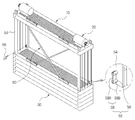
그리고 상기 고정 발판(10) 프레임(12)과 각 승강 발판(30) 프레임(34)의 일측면에는, 즉 작업대상물의 반대 측 작업자가 등지고 있는 방향으로 승강에 따른 절첩 가능하게 마련되는 각각의 안전부재(60)를 포함한다. Each side of the
안전부재(60)는 각 프레임(12)(32)의 대응되는 위치에 마련되는 각각 가이드 레일(62)과, 상기 각 가이드 레일(62)에 각 끝단이 삽입되어 슬라이딩 가능하게 구비되는 각각의 안전 바(64)를 포함하되, 상기 안전 바(64)는 X자 형태로 마련된다. The
상기 가이드 레일 상에 안전 바의 슬라이딩 가능하게 구비되는 구조는 통상적인 구조로, 안전 바의 각 끝단에 구름되는 롤러 등을 장착하여 가이드 레일로부터 이탈되지 않도록 마련되는 것으로, 이러한 구조 이외에 공지된 어떠한 구조를 적용하여도 무방하다. The structure of the safety bar slidably mounted on the guide rail is of a conventional structure and is provided so as not to be detached from the guide rail by mounting a roller or the like rolling on each end of the safety bar. May be applied.
그에 따라 상기 안전부재는 승강 발판의 하강시에는 펴져 X자 형태로 형성됨에 따라 작업자가 추락할 수 있는 것을 방지하여, 높은 안전성을 확보할 수 있는 조건을 가진다. Accordingly, the safety member is formed in an X-shape when the elevating foot is lowered, thereby preventing a worker from falling down and having a condition for securing high safety.
아울러, 상강 발판의 상승시에는 서로 겹쳐지면서 가이드 레일으로 접혀짐에 따라 승강에는 아무런 지장을 초래하지 않고 원활하게 절첩이 이루어질 수 있는 것이다. In addition, at the time of the rise of the upper stiffener, the guide rails overlap with each other and can be folded smoothly without causing any trouble to the elevating and lowering.
1 : 다단 승강형 족장
10 : 고정 발판 12,32 : 프레임
14,34 : 플레이트 20 : 구동모터
22 : 승강 와이어 로프 24 : 권취 휠
30 : 승강 발판 40 : 고정 와이어 로프
50 : 지지수단 52 : 러그
54 : 지지대 55 : 결합구
56 : 고정래치 58 : 래치 잠금부재
58A : 회동편 58B : 고정핀
60 : 안전부재 62 : 가아드 레일
64 : 안전 바1: Multi-level elevated chieftain
10: fixed
14, 34: Plate 20: Drive motor
22: lifting wire rope 24: winding wheel
30: lift platform 40: fixed wire rope
50: support means 52: rug
54: support member 55: coupling member
56: fixing latch 58: latch lock member
58A:
60: safety member 62: guide rail
64: Safety Bar
Claims (7)
상기 고정 발판의 상면 양측에 각각의 승강 와이어 로프가 권취된 권취 휠을 포함하여 마련되는 각각의 구동모터;
상기 고정 발판의 하부에 상기 각 승강 와이어 로프가 관통되어 순차적으로 승강 가능하도록 연결되는 복수의 승강 발판; 및
상기 고정 발판 및 각 승강 발판 사이의 각 모서리에는 작업공간의 높이를 확정하기 위해 연결 고정되는 고정 와이어 로프;를 포함하는 것을 특징으로 하는 다단 승강형 족장. A fixed footrest fixed to an upper portion of the workpiece;
A plurality of drive motors provided on both sides of the upper surface of the fixed footrest, each of the drive motors including a take-up wheel around which a respective hoisting wire rope is wound;
A plurality of elevating foots connected to the lower portion of the fixed footrest so that the elevating wire ropes pass through the elevating wire ropes in a sequential manner; And
And a fixed wire rope connected to each corner between the fixed footrest and each of the elevating footrests to fix the height of the work space.
상기 고정 발판 및 각 승강 발판 사이에는 하강 후 흔들림을 방지하기 위한 지지수단을 더 포함하는 것을 특징으로 하는 다단 승강형 족장. The method according to claim 1,
Further comprising support means between the fixed footrest and each of the elevating footrests for preventing shaking after descending.
상기 지지수단은 상기 고정 발판 및 각 승강 발판의 각 프레임 상면의 모서리에 구비되는 각각의 러그, 상기 고정 발판의 프레임과 승강 발판의 프레임 밑면에 상단이 회전 가능하게 결합되며 하단은 상기 각 러그와 맞닿아 결합구에 의해 탈착되도록 절첩 가능하게 마련되는 각각의 지지대를 포함하는 것을 특징으로 하는 다단 승강형 족장. 3. The method of claim 2,
Wherein the supporting means comprises: an upper end rotatably coupled to a lower surface of a frame of the fixed foot and a frame of the elevating foot, and a lower end rotatably coupled to the lower end of the frame, And each of the supporting rods is provided so as to be foldable so as to be detachable by the coupling means.
상기 결합구는 러그와 지지대를 일측에서 관통하는 고정래치, 상기 관통된 고정래치의 타측에 체결되는 래치 잠금부재를 포함하는 것을 특징으로 하는 다단 승강형 족장. The method of claim 3,
Wherein the coupling portion includes a fixing latch that penetrates the lug and the supporting member from one side, and a latch lock member that is fastened to the other side of the through-hole fixing latch.
상기 래치 잠금부재는 관통된 고정래치의 일측에 회전 가능하게 구비되는 회동편, 상기 회동편의 타측은 고정 핀에 의해 고정래치의 타측으로 고정되게 마련되는 것을 특징으로 하는 다단 승강형 족장. 5. The method of claim 4,
Wherein the latch lock member is a pivotal piece rotatably provided on one side of a penetrating fixed latch, and the other side of the pivotal movement member is fixed to the other side of the fixed latch by a fixed pin.
상기 고정 발판 프레임과 각 승강 발판 프레임의 일측면에는 승강에 따른 절첩 가능하게 마련되는 각각의 안전부재를 포함하는 것을 특징으로 하는 다단 승강형 족장. 6. The method according to any one of claims 1 to 5,
And a plurality of safety members provided on one side of the fixed foot frame and each of the elevating foot frames to be foldable in accordance with the elevation.
상기 안전부재는 각 프레임의 대응되는 위치에 마련되는 각각 가이드 레일, 상기 각 가이드 레일에 각 끝단이 삽입되어 슬라이딩 가능하게 구비되는 각각의 안전 바를 포함하되, 상기 안전 바는 X자 형태로 마련되는 것을 특징으로 하는 다단 승강형 족장.
The method according to claim 6,
The safety member includes guide rails provided at corresponding positions of the frames, and safety bars slidably inserted into the respective guide rails, wherein the safety bars are formed in an X-shape It is characterized by a multistory elevator chieftain.
Priority Applications (1)
| Application Number | Priority Date | Filing Date | Title |
|---|---|---|---|
| KR1020160058077A KR101800622B1 (en) | 2016-05-12 | 2016-05-12 | Multi-type lifting scaffold |
Applications Claiming Priority (1)
| Application Number | Priority Date | Filing Date | Title |
|---|---|---|---|
| KR1020160058077A KR101800622B1 (en) | 2016-05-12 | 2016-05-12 | Multi-type lifting scaffold |
Publications (2)
| Publication Number | Publication Date |
|---|---|
| KR20170127689A true KR20170127689A (en) | 2017-11-22 |
| KR101800622B1 KR101800622B1 (en) | 2017-11-23 |
Family
ID=60809563
Family Applications (1)
| Application Number | Title | Priority Date | Filing Date |
|---|---|---|---|
| KR1020160058077A KR101800622B1 (en) | 2016-05-12 | 2016-05-12 | Multi-type lifting scaffold |
Country Status (1)
| Country | Link |
|---|---|
| KR (1) | KR101800622B1 (en) |
Cited By (2)
| Publication number | Priority date | Publication date | Assignee | Title |
|---|---|---|---|---|
| CN114718291A (en) * | 2022-04-27 | 2022-07-08 | 湖北众利工程机械有限公司 | Automatic lifting scaffold easy to disassemble and assemble |
| CN114718291B (en) * | 2022-04-27 | 2024-05-10 | 湖北众利工程机械有限公司 | Easy-to-disassemble automatic lifting scaffold |
Family Cites Families (2)
| Publication number | Priority date | Publication date | Assignee | Title |
|---|---|---|---|---|
| KR100911088B1 (en) * | 2007-12-13 | 2009-08-06 | 현대자동차주식회사 | Structure of hood latch for vehicle |
| KR101279362B1 (en) * | 2013-04-04 | 2013-07-04 | 주식회사 시아플랜건축사사무소 | Architectural ceiling storage balcony hack |
-
2016
- 2016-05-12 KR KR1020160058077A patent/KR101800622B1/en active IP Right Grant
Cited By (2)
| Publication number | Priority date | Publication date | Assignee | Title |
|---|---|---|---|---|
| CN114718291A (en) * | 2022-04-27 | 2022-07-08 | 湖北众利工程机械有限公司 | Automatic lifting scaffold easy to disassemble and assemble |
| CN114718291B (en) * | 2022-04-27 | 2024-05-10 | 湖北众利工程机械有限公司 | Easy-to-disassemble automatic lifting scaffold |
Also Published As
| Publication number | Publication date |
|---|---|
| KR101800622B1 (en) | 2017-11-23 |
Similar Documents
| Publication | Publication Date | Title |
|---|---|---|
| JP4886286B2 (en) | Temporary scaffolding unit | |
| KR101808289B1 (en) | Multi-type lifting scaffold | |
| JP4092346B2 (en) | Construction method and dismantling method of scaffold for high-rise building | |
| KR20150127559A (en) | The Folding Suspended Scaffoldings | |
| JP2010115758A (en) | Portable workbench device | |
| JP4898255B2 (en) | Mobile scaffolding and powerless descent device | |
| KR101800622B1 (en) | Multi-type lifting scaffold | |
| JP2007182281A (en) | Control panel inspection table device for elevator without machine room | |
| KR200378217Y1 (en) | Scaffolding for the high ground working | |
| JP4108076B2 (en) | Construction method and dismantling method of scaffold for high-rise building | |
| JPH08100517A (en) | Vertically movable scaffold | |
| JP2002046951A (en) | Scaffold apparatus for maintenance of elevator | |
| JP2008214062A (en) | Lifting device and structural material mounting method | |
| JP5581476B2 (en) | Lifting type moving scaffold | |
| JP3662064B2 (en) | Manual lifting floor device | |
| JP3193609B2 (en) | Elevator installation method | |
| WO2018173135A1 (en) | Elevator apparatus | |
| KR102175558B1 (en) | scaffold system | |
| KR101769041B1 (en) | A going up and down worktable for work scaffold and concrete mold system comprising the same | |
| JP3640835B2 (en) | Aerial work platform equipment | |
| JP2004143677A (en) | Carrying in/out device of construction machine and material | |
| JP5647772B2 (en) | Lifting movable overhang scaffold | |
| JP5305432B2 (en) | Moving scaffold | |
| CN114104939B (en) | Steel framework hoisting process, hoisting equipment and auxiliary device | |
| KR102396527B1 (en) | Lifting Apparatus for Working Platform |
Legal Events
| Date | Code | Title | Description |
|---|---|---|---|
| E701 | Decision to grant or registration of patent right | ||
| GRNT | Written decision to grant |