KR20170122789A - Optical system with switchable diffuser - Google Patents
Optical system with switchable diffuser Download PDFInfo
- Publication number
- KR20170122789A KR20170122789A KR1020177027195A KR20177027195A KR20170122789A KR 20170122789 A KR20170122789 A KR 20170122789A KR 1020177027195 A KR1020177027195 A KR 1020177027195A KR 20177027195 A KR20177027195 A KR 20177027195A KR 20170122789 A KR20170122789 A KR 20170122789A
- Authority
- KR
- South Korea
- Prior art keywords
- optical
- optical system
- state
- switchable diffuser
- light
- Prior art date
Links
Images


Classifications
-
- G—PHYSICS
- G02—OPTICS
- G02B—OPTICAL ELEMENTS, SYSTEMS OR APPARATUS
- G02B5/00—Optical elements other than lenses
- G02B5/02—Diffusing elements; Afocal elements
-
- F—MECHANICAL ENGINEERING; LIGHTING; HEATING; WEAPONS; BLASTING
- F21—LIGHTING
- F21V—FUNCTIONAL FEATURES OR DETAILS OF LIGHTING DEVICES OR SYSTEMS THEREOF; STRUCTURAL COMBINATIONS OF LIGHTING DEVICES WITH OTHER ARTICLES, NOT OTHERWISE PROVIDED FOR
- F21V14/00—Controlling the distribution of the light emitted by adjustment of elements
- F21V14/003—Controlling the distribution of the light emitted by adjustment of elements by interposition of elements with electrically controlled variable light transmissivity, e.g. liquid crystal elements or electrochromic devices
-
- G—PHYSICS
- G02—OPTICS
- G02B—OPTICAL ELEMENTS, SYSTEMS OR APPARATUS
- G02B5/00—Optical elements other than lenses
- G02B5/02—Diffusing elements; Afocal elements
- G02B5/0205—Diffusing elements; Afocal elements characterised by the diffusing properties
- G02B5/021—Diffusing elements; Afocal elements characterised by the diffusing properties the diffusion taking place at the element's surface, e.g. by means of surface roughening or microprismatic structures
- G02B5/0221—Diffusing elements; Afocal elements characterised by the diffusing properties the diffusion taking place at the element's surface, e.g. by means of surface roughening or microprismatic structures the surface having an irregular structure
-
- F—MECHANICAL ENGINEERING; LIGHTING; HEATING; WEAPONS; BLASTING
- F21—LIGHTING
- F21V—FUNCTIONAL FEATURES OR DETAILS OF LIGHTING DEVICES OR SYSTEMS THEREOF; STRUCTURAL COMBINATIONS OF LIGHTING DEVICES WITH OTHER ARTICLES, NOT OTHERWISE PROVIDED FOR
- F21V23/00—Arrangement of electric circuit elements in or on lighting devices
- F21V23/04—Arrangement of electric circuit elements in or on lighting devices the elements being switches
- F21V23/0442—Arrangement of electric circuit elements in or on lighting devices the elements being switches activated by means of a sensor, e.g. motion or photodetectors
-
- G—PHYSICS
- G02—OPTICS
- G02B—OPTICAL ELEMENTS, SYSTEMS OR APPARATUS
- G02B5/00—Optical elements other than lenses
- G02B5/02—Diffusing elements; Afocal elements
- G02B5/0273—Diffusing elements; Afocal elements characterized by the use
- G02B5/0278—Diffusing elements; Afocal elements characterized by the use used in transmission
-
- G—PHYSICS
- G02—OPTICS
- G02B—OPTICAL ELEMENTS, SYSTEMS OR APPARATUS
- G02B5/00—Optical elements other than lenses
- G02B5/02—Diffusing elements; Afocal elements
- G02B5/0273—Diffusing elements; Afocal elements characterized by the use
- G02B5/0294—Diffusing elements; Afocal elements characterized by the use adapted to provide an additional optical effect, e.g. anti-reflection or filter
-
- G—PHYSICS
- G02—OPTICS
- G02F—OPTICAL DEVICES OR ARRANGEMENTS FOR THE CONTROL OF LIGHT BY MODIFICATION OF THE OPTICAL PROPERTIES OF THE MEDIA OF THE ELEMENTS INVOLVED THEREIN; NON-LINEAR OPTICS; FREQUENCY-CHANGING OF LIGHT; OPTICAL LOGIC ELEMENTS; OPTICAL ANALOGUE/DIGITAL CONVERTERS
- G02F1/00—Devices or arrangements for the control of the intensity, colour, phase, polarisation or direction of light arriving from an independent light source, e.g. switching, gating or modulating; Non-linear optics
- G02F1/01—Devices or arrangements for the control of the intensity, colour, phase, polarisation or direction of light arriving from an independent light source, e.g. switching, gating or modulating; Non-linear optics for the control of the intensity, phase, polarisation or colour
- G02F1/13—Devices or arrangements for the control of the intensity, colour, phase, polarisation or direction of light arriving from an independent light source, e.g. switching, gating or modulating; Non-linear optics for the control of the intensity, phase, polarisation or colour based on liquid crystals, e.g. single liquid crystal display cells
- G02F1/133—Constructional arrangements; Operation of liquid crystal cells; Circuit arrangements
- G02F1/13306—Circuit arrangements or driving methods for the control of single liquid crystal cells
-
- G—PHYSICS
- G02—OPTICS
- G02F—OPTICAL DEVICES OR ARRANGEMENTS FOR THE CONTROL OF LIGHT BY MODIFICATION OF THE OPTICAL PROPERTIES OF THE MEDIA OF THE ELEMENTS INVOLVED THEREIN; NON-LINEAR OPTICS; FREQUENCY-CHANGING OF LIGHT; OPTICAL LOGIC ELEMENTS; OPTICAL ANALOGUE/DIGITAL CONVERTERS
- G02F1/00—Devices or arrangements for the control of the intensity, colour, phase, polarisation or direction of light arriving from an independent light source, e.g. switching, gating or modulating; Non-linear optics
- G02F1/01—Devices or arrangements for the control of the intensity, colour, phase, polarisation or direction of light arriving from an independent light source, e.g. switching, gating or modulating; Non-linear optics for the control of the intensity, phase, polarisation or colour
- G02F1/13—Devices or arrangements for the control of the intensity, colour, phase, polarisation or direction of light arriving from an independent light source, e.g. switching, gating or modulating; Non-linear optics for the control of the intensity, phase, polarisation or colour based on liquid crystals, e.g. single liquid crystal display cells
- G02F1/133—Constructional arrangements; Operation of liquid crystal cells; Circuit arrangements
- G02F1/1333—Constructional arrangements; Manufacturing methods
- G02F1/1334—Constructional arrangements; Manufacturing methods based on polymer dispersed liquid crystals, e.g. microencapsulated liquid crystals
-
- G—PHYSICS
- G02—OPTICS
- G02F—OPTICAL DEVICES OR ARRANGEMENTS FOR THE CONTROL OF LIGHT BY MODIFICATION OF THE OPTICAL PROPERTIES OF THE MEDIA OF THE ELEMENTS INVOLVED THEREIN; NON-LINEAR OPTICS; FREQUENCY-CHANGING OF LIGHT; OPTICAL LOGIC ELEMENTS; OPTICAL ANALOGUE/DIGITAL CONVERTERS
- G02F1/00—Devices or arrangements for the control of the intensity, colour, phase, polarisation or direction of light arriving from an independent light source, e.g. switching, gating or modulating; Non-linear optics
- G02F1/01—Devices or arrangements for the control of the intensity, colour, phase, polarisation or direction of light arriving from an independent light source, e.g. switching, gating or modulating; Non-linear optics for the control of the intensity, phase, polarisation or colour
- G02F1/13—Devices or arrangements for the control of the intensity, colour, phase, polarisation or direction of light arriving from an independent light source, e.g. switching, gating or modulating; Non-linear optics for the control of the intensity, phase, polarisation or colour based on liquid crystals, e.g. single liquid crystal display cells
- G02F1/133—Constructional arrangements; Operation of liquid crystal cells; Circuit arrangements
- G02F1/1333—Constructional arrangements; Manufacturing methods
- G02F1/1335—Structural association of cells with optical devices, e.g. polarisers or reflectors
- G02F1/133504—Diffusing, scattering, diffracting elements
-
- G—PHYSICS
- G02—OPTICS
- G02F—OPTICAL DEVICES OR ARRANGEMENTS FOR THE CONTROL OF LIGHT BY MODIFICATION OF THE OPTICAL PROPERTIES OF THE MEDIA OF THE ELEMENTS INVOLVED THEREIN; NON-LINEAR OPTICS; FREQUENCY-CHANGING OF LIGHT; OPTICAL LOGIC ELEMENTS; OPTICAL ANALOGUE/DIGITAL CONVERTERS
- G02F1/00—Devices or arrangements for the control of the intensity, colour, phase, polarisation or direction of light arriving from an independent light source, e.g. switching, gating or modulating; Non-linear optics
- G02F1/01—Devices or arrangements for the control of the intensity, colour, phase, polarisation or direction of light arriving from an independent light source, e.g. switching, gating or modulating; Non-linear optics for the control of the intensity, phase, polarisation or colour
- G02F1/13—Devices or arrangements for the control of the intensity, colour, phase, polarisation or direction of light arriving from an independent light source, e.g. switching, gating or modulating; Non-linear optics for the control of the intensity, phase, polarisation or colour based on liquid crystals, e.g. single liquid crystal display cells
- G02F1/137—Devices or arrangements for the control of the intensity, colour, phase, polarisation or direction of light arriving from an independent light source, e.g. switching, gating or modulating; Non-linear optics for the control of the intensity, phase, polarisation or colour based on liquid crystals, e.g. single liquid crystal display cells characterised by the electro-optical or magneto-optical effect, e.g. field-induced phase transition, orientation effect, guest-host interaction or dynamic scattering
- G02F1/13756—Devices or arrangements for the control of the intensity, colour, phase, polarisation or direction of light arriving from an independent light source, e.g. switching, gating or modulating; Non-linear optics for the control of the intensity, phase, polarisation or colour based on liquid crystals, e.g. single liquid crystal display cells characterised by the electro-optical or magneto-optical effect, e.g. field-induced phase transition, orientation effect, guest-host interaction or dynamic scattering the liquid crystal selectively assuming a light-scattering state
Abstract
조명 컴포넌트 및 조명 컴포넌트와 광학적으로 연결되는(in optical communication) 스위칭가능 확산기를 포함하는 광학 시스템. 광학 시스템은 저-흡수 광학 컴포넌트를 추가로 포함할 수 있다. 스위칭가능 확산기 및/또는 저-흡수 광학 컴포넌트의 적어도 하나의 외부 표면은 광 방향전환 구조체들을 포함한다. 스위칭가능 확산기가 제1 상태에 있고 광학 시스템이 광출력을 생성할 때, 광 방향전환 구조체들은 적어도 하나의 방향에서 광학 시스템의 광출력의 반치전폭(full width at half-maximum, FWHM)을, 광 방향전환 구조체들을 포함하지 않는 다른 점에서 동등한(otherwise equivalent) 광학 시스템의 광출력의 FWHM에 비해 적어도 5도만큼 증가시키도록 구성된다.An optical system comprising a switchable diffuser in optical communication with an illumination component and an illumination component. The optical system may further comprise a low-absorption optical component. At least one outer surface of the switchable diffuser and / or the low-absorption optical component includes light direction switching structures. When the switchable diffuser is in the first state and the optical system produces an optical output, the optical directional switching structures are configured to adjust the full width at half-maximum (FWHM) of the optical output of the optical system in at least one direction, At least 5 degrees higher than the FWHM of the optical output of the equivalent equivalent optical system at other points that do not include redirecting structures.
Description
광학 시스템은 광출력의 균일성을 향상시키기 위해 확산기를 포함할 수 있다. 일부 경우들에서, 광학 시스템 및 스위칭가능 확산기로부터의 광출력을 전기적으로 조정할 수 있는 것이 바람직할 수 있으며, 스위칭가능 확산기는 고분자 분산형 액정(polymer dispersed liquid crystal, PDLC) 층을 포함할 수 있으며, 이 목적을 위해 사용될 수 있다.The optical system may include a diffuser to improve the uniformity of the light output. In some cases, it may be desirable to be able to electrically adjust the light output from the optical system and the switchable diffuser, and the switchable diffuser may comprise a layer of polymer dispersed liquid crystal (PDLC) Can be used for this purpose.
본 명세서의 일부 양태들에서, 조명 컴포넌트, 조명 컴포넌트와 광학적으로 연결되는(in optical communication) 스위칭가능 확산기, 및 조명 컴포넌트와 광학적으로 연결되고 스위칭가능 확산기와 광학적으로 연결되는 저-흡수 광학 컴포넌트를 포함하는 광학 시스템이 제공된다. 스위칭가능 확산기는 적어도 제1 상태 및 제2 상태를 갖는다. 제1 상태는 제1 탁도에 의해 특징지어지고, 제2 상태는 제1 탁도와 상이한 제2 탁도에 의해 특징지어진다. 저-흡수 광학 컴포넌트는 대향하는 제1 및 제2 외부 표면들을 포함하며, 여기서 제1 및 제2 외부 표면들 중 적어도 하나는 광 방향전환 구조체들을 포함한다. 스위칭가능 확산기가 제1 상태에 있고 광학 시스템이 광출력을 생성할 때, 광 방향전환 구조체들은 적어도 하나의 방향에서 광학 시스템의 광출력의 반치전폭(full width at half-maximum, FWHM)을, 광 방향전환 구조체들을 포함하지 않는 다른 점에서 동등한(otherwise equivalent) 광학 시스템의 광출력의 FWHM에 비해 적어도 5도만큼 증가시키도록 구성된다.In some aspects of the disclosure, the light source includes a light-emitting component, a switchable diffuser in optical communication with the light component, and a low-absorption optical component optically coupled to the switchable diffuser and optically coupled to the illumination component Is provided. The switchable diffuser has at least a first state and a second state. The first condition is characterized by a first turbidity and the second condition is characterized by a second turbidity different from the first turbidity. The low-absorption optical component includes opposing first and second outer surfaces, wherein at least one of the first and second outer surfaces includes light direction switching structures. When the switchable diffuser is in the first state and the optical system produces an optical output, the optical directional switching structures are configured to adjust the full width at half-maximum (FWHM) of the optical output of the optical system in at least one direction, At least 5 degrees higher than the FWHM of the optical output of the equivalent equivalent optical system at other points that do not include redirecting structures.
본 명세서의 일부 양태들에서, 조명 컴포넌트 및 조명 컴포넌트와 광학적으로 연결되는 스위칭가능 확산기를 포함하는 광학 시스템이 제공된다. 스위칭가능 확산기는 적어도 제1 상태 및 제2 상태를 갖는다. 제1 상태는 제1 탁도에 의해 특징지어지고, 제2 상태는 제1 탁도와 상이한 제2 탁도에 의해 특징지어진다. 스위칭가능 확산기는 제1 외부 층과 제2 외부 층 사이에 배치된 활성층을 포함한다. 제1 외부 층은 활성층 반대편의 제1 외부 표면을 갖고, 제2 외부 층은 활성층 반대편의 제2 외부 표면을 가지며, 이때 제2 외부 층은 조명 컴포넌트를 향한다. 제1 및 제2 외부 표면들 중 적어도 하나는 광 방향전환 구조체들을 포함한다. 스위칭가능 확산기가 제1 상태에 있고 광학 시스템이 광출력을 생성할 때, 광 방향전환 구조체들은 적어도 하나의 방향에서 광학 시스템의 광출력의 반치전폭(FWHM)을, 광 방향전환 구조체들을 포함하지 않는 다른 점에서 동등한 광학 시스템의 광출력의 FWHM에 비해 적어도 5도만큼 증가시키도록 구성된다.In some aspects of the disclosure, an optical system is provided that includes a switchable diffuser optically coupled to the illumination component and the illumination component. The switchable diffuser has at least a first state and a second state. The first condition is characterized by a first turbidity and the second condition is characterized by a second turbidity different from the first turbidity. The switchable diffuser comprises an active layer disposed between the first outer layer and the second outer layer. The first outer layer has a first outer surface opposite the active layer and the second outer layer has a second outer surface opposite the active layer with the second outer layer facing the illumination component. At least one of the first and second outer surfaces includes light direction switching structures. When the switchable diffuser is in the first state and the optical system produces an optical output, the optical directional switching structures are arranged such that the FWHM of the optical output of the optical system in at least one direction, In other respects, by at least 5 degrees relative to the FWHM of the optical output of the equivalent optical system.
본 명세서의 일부 양태들에서, 조명 컴포넌트, 조명 컴포넌트와 광학적으로 연결되는 스위칭가능 확산기, 및 조명 컴포넌트와 광학적으로 연결되고 스위칭가능 확산기와 광학적으로 연결되는 저-흡수 광학 컴포넌트를 포함하는 광학 시스템이 제공된다. 스위칭가능 확산기는 적어도 제1 상태 및 제2 상태를 갖는다. 제1 상태는 제1 탁도에 의해 특징지어지고, 제2 상태는 제1 탁도와 상이한 제2 탁도에 의해 특징지어진다. 스위칭가능 확산기는 제1 외부 층과 제2 외부 층 사이에 배치된 활성층을 포함한다. 제1 외부 층은 활성층 반대편의 제1 외부 표면을 갖고, 제2 외부 층은 활성층 반대편의 제2 외부 표면을 갖는다. 저-흡수 광학 컴포넌트는 대향하는 제3 및 제4 외부 표면들을 포함한다. 제1, 제2, 제3 및 제4 외부 표면들 중 적어도 하나는 광 방향전환 구조체들을 포함한다. 스위칭가능 확산기가 제1 상태에 있고 광학 시스템이 광출력을 생성할 때, 광 방향전환 구조체들은 적어도 하나의 방향에서 광학 시스템의 광출력의 반치전폭(FWHM)을, 광 방향전환 구조체들을 포함하지 않는 다른 점에서 동등한 광학 시스템의 광출력의 FWHM에 비해 적어도 5도만큼 증가시키도록 구성된다.In some aspects of the disclosure, an optical system is provided that includes an illumination component, a switchable diffuser optically coupled to the illumination component, and a low-absorption optical component optically coupled to the switchable diffuser and optically coupled to the illumination component do. The switchable diffuser has at least a first state and a second state. The first condition is characterized by a first turbidity and the second condition is characterized by a second turbidity different from the first turbidity. The switchable diffuser comprises an active layer disposed between the first outer layer and the second outer layer. The first outer layer has a first outer surface opposite the active layer and the second outer layer has a second outer surface opposite the active layer. The low-absorption optical component includes opposing third and fourth outer surfaces. At least one of the first, second, third and fourth outer surfaces comprises light direction switching structures. When the switchable diffuser is in the first state and the optical system produces an optical output, the optical directional switching structures are arranged such that the FWHM of the optical output of the optical system in at least one direction, In other respects, by at least 5 degrees relative to the FWHM of the optical output of the equivalent optical system.
도 1a는 광 방향전환 구조체들을 포함하는 스위칭가능 확산기를 갖는 광학 시스템의 개략적인 단면도이다.
도 1b는 광 방향전환 구조체들을 갖지 않는 스위칭가능 확산기를 갖는 다른 점에서 동등한 광학 시스템의 개략적인 단면도이다.
도 2a는 광 방향전환 구조체들을 포함하는 저-흡수 광학 컴포넌트를 갖는 광학 시스템의 개략적인 단면도이다.
도 2b는 광 방향전환 구조체들을 갖지 않는 저-흡수 광학 컴포넌트를 갖는 다른 점에서 동등한 광학 시스템의 개략적인 단면도이다.
도 3a 내지 도 3c는 광학 시스템들의 개략적인 측면도들이다.
도 4a 및 도 4b는 광학 시스템들의 광출력 분포들의 평면도들을 개략적으로 도시한다.
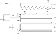
도 5a는 광 방향전환 구조체들을 포함하는 스위칭가능 확산기를 갖고, 광 방향전환 구조체들을 포함하는 저-흡수 광학 컴포넌트를 갖는 광학 시스템의 단면도이다.
도 5b는 광 방향전환 구조체들을 갖지 않는 스위칭가능 확산기를 갖는, 다른 점에서 동등한 광학 시스템의 단면도이다.
도 5c는 광 방향전환 구조체들을 갖지 않는 스위칭가능 확산기를 갖고, 광 방향전환 구조체들을 갖지 않는 저-흡수 광학 컴포넌트를 갖는, 다른 점에서 동등한 광학 시스템의 단면도이다.
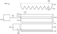
도 6a는 광 방향전환 구조체들을 포함하는 스위칭가능 확산기를 갖고, 광 방향전환 구조체들을 포함하는 저-흡수 광학 컴포넌트를 갖는 광학 시스템의 단면도이다.
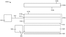
도 6b는 광 방향전환 구조체들을 갖지 않는 스위칭가능 확산기를 갖고, 광 방향전환 구조체들을 갖지 않는 저-흡수 광학 컴포넌트를 갖는, 다른 점에서 동등한 광학 시스템의 단면도이다.
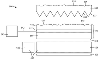
도 7a는 광 방향전환 구조체들을 포함하는 스위칭가능 확산기를 갖고, 광 방향전환 구조체들을 포함하는 저-흡수 광학 컴포넌트를 갖는 광학 시스템의 단면도이다.
도 7b는 광 방향전환 구조체들을 갖지 않는 스위칭가능 확산기를 갖고, 광 방향전환 구조체들을 갖지 않는 저-흡수 광학 컴포넌트를 갖는, 다른 점에서 동등한 광학 시스템의 단면도이다.
도 8 및 도 9는 광학 시스템들의 개략적인 단면도들이다.
도 10은 광학 시스템의 단면도이다.
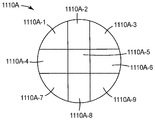
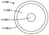
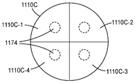
도 11a 내지 도 11c는 스위칭가능 확산기들의 평면도들이다.
도 12는 광학 컴포넌트의 단면도이다.
도 13은 조명 시스템의 개략도이다.
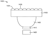
도 14는 광학 시스템의 단면도이다.
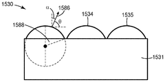
도 15는 광학 컴포넌트의 일부분의 개략적인 단면도이다.
도 16은 광학 컴포넌트의 일부분의 개략적인 단면도이다.
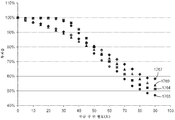
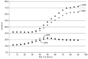
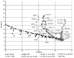
도 17은 광 방향전환 구조체들을 갖는 광학 컴포넌트를 통한 투과율 대 광 방향전환 구조체들의 부분 구 반 원호 각(partial sphere half arc angle)의 플롯이다.
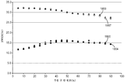
도 18은 광 방향전환 구조체들을 갖는 광학 컴포넌트를 통한 출력 분포의 반치반폭(half width at half maximum) 대 광 방향전환 구조체들의 부분 구 반 원호 각의 플롯이다.
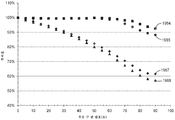
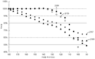
도 19는 광 방향전환 구조체들을 갖는 광학 컴포넌트를 통한 투과율 대 광 방향전환 구조체들의 부분 구 반 원호 각의 플롯이다.
도 20은 광 방향전환 구조체들을 갖는 광학 컴포넌트를 통한 출력 분포의 반치반폭 대 광 방향전환 구조체들의 부분 구 반 원호 각의 플롯이다.
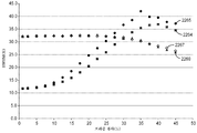
도 21은 광 방향전환 구조체들을 갖는 광학 컴포넌트를 통한 투과율 대 광 방향전환 구조체들의 프리즘 꼭지각(apex angle)의 플롯이다.
도 22는 광 방향전환 구조체들을 갖는 광학 컴포넌트를 통한 출력 분포의 반치반폭 대 광 방향전환 구조체들의 프리즘 경사의 플롯이다.
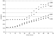
도 23은 광 방향전환 구조체들을 갖는 광학 컴포넌트를 통한 투과율 대 광 방향전환 구조체들의 프리즘 꼭지각의 플롯이다.
도 24는 광 방향전환 구조체들을 갖는 광학 컴포넌트를 통한 출력 분포의 반치반폭 대 광 방향전환 구조체들의 프리즘 경사의 플롯이다.
도 25 내지 도 29는 광학 컴포넌트를 통한 출력 분포의 반치반폭 대 광학 컴포넌트를 통한 투과율의 플롯들이다.1A is a schematic cross-sectional view of an optical system having a switchable diffuser comprising light direction switching structures.
1B is a schematic cross-sectional view of an equivalent optical system in another point with a switchable diffuser without light direction switching structures.
2A is a schematic cross-sectional view of an optical system having a low-absorption optical component comprising light direction switching structures.
Figure 2B is a schematic cross-sectional view of an equivalent optical system in another respect with a low-absorption optical component without light-diverting structures.
Figures 3A-3C are schematic side views of optical systems.
Figures 4A and 4B schematically show plan views of optical power distributions of optical systems.
5A is a cross-sectional view of an optical system having a low-absorption optical component including a light direction switching structures, having a switchable diffuser comprising light direction switching structures.
Figure 5B is a cross-sectional view of an otherwise identical optical system with a switchable diffuser without light direction change structures.
5C is a cross-sectional view of an otherwise identical optical system with a low-absorption optical component having a switchable diffuser without light direction change structures and without light direction change structures.
6A is a cross-sectional view of an optical system having a low-absorption optical component including a light direction switching structure, having a switchable diffuser comprising light direction switching structures.
FIG. 6B is a cross-sectional view of an otherwise identical optical system with a low-absorption optical component having a switchable diffuser without light-diverting structures and without light-diverting structures.
7A is a cross-sectional view of an optical system having a low-absorption optical component including a light direction switching structure, having a switchable diffuser comprising light direction switching structures.
Figure 7B is a cross-sectional view of an otherwise identical optical system with a low-absorption optical component having a switchable diffuser without light direction change structures and without light direction change structures.
Figures 8 and 9 are schematic cross-sectional views of optical systems.
10 is a cross-sectional view of the optical system.
11A-11C are top views of the switchable diffusers.
12 is a cross-sectional view of an optical component.
13 is a schematic diagram of an illumination system.
14 is a cross-sectional view of the optical system.
15 is a schematic cross-sectional view of a portion of an optical component.
16 is a schematic cross-sectional view of a portion of an optical component.
Figure 17 is a plot of the transmission through the optical component with the light direction switching structures versus the partial sphere half arc angle of the light direction switching structures.
FIG. 18 is a plot of half-width at half maximum of the power distribution through the optical component with the light direction switching structures versus the partial half-arc angle of the light direction switching structures.
19 is a plot of the transmittance versus the partial spherical half arc angle of the optical directional shift structures through the optical component with the optical directional shift structures.
Figure 20 is a plot of the half sphere half-arc versus partial half-arc angle of the output distribution through the optical component with the light direction change structures.
21 is a plot of the prism apex angle of the transmittance versus the light direction change structures through the optical component with the light direction change structures.
Figure 22 is a plot of the prism inclination of the half-width half-width versus light direction switching structures of the output distribution through the optical component with the light direction switching structures.
Figure 23 is a plot of the transmittance versus the prism apex angle of the light redirecting structures through the optical component with the redirecting structures.
24 is a plot of the prism tilt of the half-width half-width versus light direction switching structures of the output distribution through the optical component with the light direction switching structures.
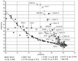
Figures 25-29 are plots of the transmittance through the half-width versus optical component of the output distribution through the optical component.
하기 설명에서, 본 명세서의 일부를 형성하고 예시로서 도시된 첨부 도면을 참조한다. 도면은 반드시 축척대로 그려진 것은 아니다. 다른 실시예들이 고려되며 본 명세서의 범주 또는 사상으로부터 벗어남이 없이 제조될 수 있다는 것이 이해되어야 한다.In the following description, reference is made to the accompanying drawings that form a part hereof and are, by way of example, shown. The drawings are not necessarily drawn to scale. It is to be understood that other embodiments are contemplated and may be made without departing from the scope or spirit of the specification.
전자적으로 조정가능한 출력 분포들을 갖는 광학 시스템들이 때때로 요구된다. 예를 들어, 실시간으로, 즉 조명 설비를 분해, 재구성 및 재조립하거나 램프를 물리적으로 조작하거나 또는 추가적인 컴포넌트를 제공 및 설치할 필요 없이, 조명기구의 상이한 유형의 조명 출력들 사이에서 스위칭할 수 있는 것이 바람직할 수 있다. 다른 예로서, 디스플레이 또는 표지판이 광시야각 모드 및 협시야각 모드를 갖는 것이 바람직할 수 있다. 광학 시스템의 광출력은 광 경로에 확산기를 배치함으로써 변경될 수 있다. 확산기가 전기적 스위칭가능 확산기인 경우, 스위칭가능 확산기의 상태를 전자적으로 변화시킴으로써 광학 시스템의 출력은 변경될 수 있다.Optical systems with electronically adjustable power distributions are sometimes required. For example, it is possible to switch between different types of lighting outputs of a luminaire, in real time, i.e. without disassembling, reconfiguring and reassembling the lighting fixtures, physically manipulating the lamps or providing and installing additional components Lt; / RTI > As another example, it may be desirable for the display or sign to have a wide viewing angle mode and a narrow viewing angle mode. The optical output of the optical system can be changed by placing a diffuser in the optical path. If the diffuser is an electrically switchable diffuser, the output of the optical system can be changed by electronically changing the state of the switchable diffuser.
광학 시스템에 고정형 확산기 및 스위칭가능 확산기를 둘 다 포함하는 것이 바람직할 수 있다. 고정형 확산기는 광학 시스템으로부터의 광의 각도 분포의 폭을, 종래의 전자적 스위칭가능 확산기로 달성가능하게 되는 것을 넘어서 증가시키는 데 사용될 수 있다. 그러나 벌크 확산기를 포함하는 것은 광이 벌크 확산기를 통과할 때 광의 후방산란을 야기하여 덜 효율적인 광학 시스템이 될 수 있다. 본 명세서에 따르면, 스위칭가능 확산기를 포함하는 광학 시스템에서 확산을 제공하기 위해 표면 구조체들을 이용하는 것은 임의의 후방산란에 비해 예기치 않게 고도의 전방산란을 제공할 수 있다는 것이 밝혀졌다. 예시들에 도시된 바와 같이, (예를 들어, 출력의 주어진 FWHM에 대한) 주어진 레벨의 광 확산을 생성하기 위해 표면 구조체들을 사용하는 것은 벌크 확산기를 사용하는 것보다 상당히 더 높은 투과율을 제공할 수 있다. 표면 구조체들은 스위칭가능 확산기 상에 존재할 수 있고/있거나 광학 시스템에 포함된 저-흡수 광학 컴포넌트일 수 있는 추가의 광학 컴포넌트 상에 존재할 수 있다.It may be desirable to include both a fixed diffuser and a switchable diffuser in the optical system. The fixed diffuser can be used to increase the width of the angular distribution of light from the optical system beyond what is achievable with conventional electronic switchable diffusers. Including a bulk diffuser, however, can result in backscattering of light as it passes through the bulk diffuser, resulting in a less efficient optical system. It has been found, in accordance with the present disclosure, that the use of surface structures to provide diffusion in an optical system comprising a switchable diffuser can provide a high degree of forward scattering unexpectedly compared to any backscattering. As shown in the examples, using surface structures to produce a given level of light diffusion (e.g., for a given FWHM of the output) can provide significantly higher transmittance than using bulk diffusers have. The surface structures may be on a switchable diffuser and / or may be on a further optical component, which may be a low-absorption optical component included in the optical system.
본 명세서에 따른 광학 시스템들은 전기적 스위칭가능 확산기를 포함하며, 하나 이상의 저-흡수 광학 컴포넌트를 포함할 수 있다. 스위칭가능 확산기 및 임의의 포함된 저-흡수 광학 컴포넌트들의 적어도 하나의 외부 표면은 광학 시스템의 광출력의 반치전폭(FWHM)을, 광 방향전환 구조체들을 포함하지 않는 다른 점에서 동등한 광학 시스템에 비해 증가시키도록 구성된 광 방향전환 구조체들을 포함한다. FWHM은 광출력의 각도 분포를 지칭한다. 광 방향전환 구조체들은 적어도 5도, 또는 적어도 7도, 또는 적어도 10도, 또는 적어도 15도, 또는 적어도 20도만큼 FWHM을 증가시킬 수 있고, 스위칭가능 확산기의 적어도 하나의 상태(예를 들어, 가장 낮은 탁도 상태)에 대해 적어도 하나의 축을 따라 45도만큼, 또는 60도만큼, 또는 90도만큼, 또는 120도만큼, 또는 150도만큼 FWHM을 증가시킬 수 있다.Optical systems according to the present disclosure include an electrically switchable diffuser and may include one or more low-absorption optical components. At least one external surface of the switchable diffuser and any included low-absorption optical components is configured to increase the full-width half-maximum (FWHM) of the optical output of the optical system relative to an equivalent optical system at other points that do not include the light- Directional switching structures. FWHM refers to the angular distribution of light output. The light redirecting structures may increase the FWHM by at least 5 degrees, or at least 7 degrees, or at least 10 degrees, or at least 15 degrees, or at least 20 degrees, and at least one state of the switchable diffuser (e.g., For example, 45 degrees, or 60 degrees, or 90 degrees, or 120 degrees, or 150 degrees along at least one axis for a given turbidity (e.g., a low turbidity state).
광 방향전환 구조체들을 포함하지 않는 비구조화된(unstructured) 컴포넌트는, 두 컴포넌트들이 동등한 재료들로 구성되며 광 방향전환 구조체들을 제외하고는 동일한 크기(예를 들어, 길이, 폭 및 평균 두께) 및 형상을 갖는 경우, 광 방향전환 구조체들을 포함하는 구조화된 컴포넌트와 다른 점에서 동등한 것으로 칭해질 수 있다.An unstructured component that does not include light redirecting structures may be configured such that the two components are composed of equivalent materials and have the same size (e.g., length, width, and average thickness) and shape , It can be referred to as being equivalent in terms of being different from the structured component including the light direction switching structures.
본 명세서에서 사용되는 바와 같이, "저-흡수" 필름 또는 컴포넌트는 램버시안 각도 분포(Lambertian angular distribution)를 갖는 표준광원(standard illuminant)(E)으로부터의 입력광의 광속의 약 20 퍼센트 미만을 흡수하는 필름 또는 컴포넌트이다. 표준광원(E)은 가시 파장 범위(380 nm 내지 780 nm)에 걸쳐 일정한 스펙트럼 파워 분포(spectral power distribution)를 갖는 등-에너지(equal-energy) 광원이다. 이에 비해, 때때로 스위치가능 확산기를 구비한 시스템에서 사용되는 루버 필름은, 램버시안 각도 분포를 갖는 표준광원(E)으로부터의 입력광의 광속의 약 30%를 흡수할 수 있다. 일부 실시예들에서, 램버시안 각도 분포를 갖는 표준광원(E)으로부터의 입력광의 광속의 약 15% 미만 또는 약 10% 미만 또는 심지어 약 5% 미만을 흡수하는 저-흡수 컴포넌트 또는 필름이 사용된다. 저-흡수 광학 컴포넌트를 사용하는 것은 광학 시스템의 효율의 원하는 레벨을 제공할 수 있다.As used herein, a "low-absorption" film or component absorbs less than about 20 percent of the light flux of input light from a standard illuminant (E) with a Lambertian angular distribution Film or component. The standard light source E is an equal-energy light source with a constant spectral power distribution over the visible wavelength range (380 nm to 780 nm). By comparison, the louver film used in systems with occasional switchable diffusers can absorb about 30% of the light flux of input light from a standard light source E with a Lambertian angular distribution. In some embodiments, a low-absorption component or film is used that absorbs less than about 15%, or less than about 10%, or even less than about 5% of the light flux of input light from a standard light source E having a Lambertian angular distribution . Using low-absorption optical components can provide the desired level of efficiency of the optical system.
일부 실시예들에서, 스위칭가능 확산기는 스멕틱(smectic) A 액정을 포함한다. 스멕틱 A 액정을 포함하는 스위칭가능 확산기는 스위칭가능 확산기가 실질적 투명 상태에 있을 때 약 3% 이하의 축상(on-axis) 탁도를 가질 수 있다. 일부 경우들에서, 축상 탁도는 1%만큼 낮을 수 있다. 대조적으로, PDLC 확산기는 그것의 가장 투명한 상태에 있을 때 5% 초과의 축상 탁도를 갖는다. PDLC 확산기의 축외(off-axis) 탁도는 그것의 투명 상태에 있을 때 5%보다 상당히 더 높은 반면, 스멕틱 A 확산기의 축외 탁도는 축외에서 낮게 유지된다. 스멕틱 A 스위칭가능 확산기 및 PDLC 스위칭가능 확산기의 최대 탁도는 100 퍼센트에 근접한다. 탁도는 ASTM D1003-13 "투명 플라스틱의 탁도 및 시감 투과율에 대한 표준 시험 방법(Standard Test Method for Haze and Luminous Transmittance of Transparent Plastics)"에 규정된 바와 같이 투과 광의 방향이 입사 빔의 방향으로부터 2.5도를 초과하여 벗어나도록 산란되는 투과 광의 백분율로 정의될 수 있다. 탁도는 ASTM D1003-13 표준을 준수하는 비와이케이-가드너 인크.(BYK-Gardner Inc.)(미국 메릴랜드주 실버 스프링스 소재)로부터 입수가능한 탁도-가드 플러스(HAZE-GARD PLUS) 측정기를 사용하여 결정될 수 있다.In some embodiments, the switchable diffuser comprises a smectic A liquid crystal. A switchable diffuser comprising a Smectic A liquid crystal may have an on-axis turbidity of less than about 3% when the switchable diffuser is in a substantially transparent state. In some cases, the axial turbidity may be as low as 1%. In contrast, the PDLC diffuser has an axial turbidity of more than 5% when in its most transparent state. The off-axis turbidity of the PDLC diffuser is significantly higher than 5% when in its transparent state, while the off-axis turbidity of the Smectic A diffuser remains off-axis. The maximum turbidity of the Smectic A switchable diffuser and the PDLC switchable diffuser is close to 100 percent. Turbidity is defined as the direction of transmitted light is 2.5 degrees from the direction of the incident beam as specified in ASTM D1003-13 "Standard Test Method for Haze and Luminous Transmittance of Transparent Plastics" Can be defined as the percentage of the transmitted light that is scattered to exceed. The turbidity may be determined using a turbidity-guard plus meter available from BYK-Gardner Inc. (Silver Springs, MD) in accordance with ASTM D1003-13 standard. have.
일부 실시예들에서, 본 명세서의 광학 시스템에 사용되는 스위칭가능 확산기는 스위칭가능 확산기의 적어도 하나의 상태(예를 들어, 가장 낮은 탁도 상태)에 대한 0도(수직 입사) 내지 약 85도(예를 들어, 스침 입사(glancing incidence))의 범위 내의 모든 입사각들에 대해 약 5 퍼센트 미만의 탁도를 갖는다. 일부 실시예들에서, 본 명세서의 광학 시스템에 사용되는 스위칭가능 확산기는 스위칭가능 확산기의 적어도 하나의 상태(예를 들어, 가장 낮은 탁도 상태)에 대한 0도 내지 약 85도의 범위 내의 모든 입사각들에 대해 약 5 퍼센트 미만의 탁도를 갖는 활성층을 포함한다.In some embodiments, the switchable diffusers used in the optical system of the present disclosure have a zero degree (normal incidence) to about 85 degrees (for example, the lowest turbidity state) for at least one state For example, glancing incidence) of less than about 5 percent for all angles of incidence. In some embodiments, the switchable diffuser used in the optical system of the present disclosure is capable of varying the angle of incidence at all angles of incidence within the range of 0 degrees to about 85 degrees for at least one state of the switchable diffuser (e.g., the lowest turbidity state) Lt; RTI ID = 0.0 > 5% < / RTI >
광학 시스템의 광출력의 FWHM을 증가시키는 광 방향전환 구조체들을 갖는 스멕틱 A 스위칭가능 확산기와 같은 저-탁도 스위칭가능 확산기의 사용은 임의의 후방산란에 비해 예기치 않게 고도의 전방산란을 제공할 수 있다. 광 방향전환 구조체들은 확산기의 표면 상에 그리고/또는 저-흡수 광학 컴포넌트의 표면 상에 있을 수 있다.The use of a low-turbidity switchable diffuser, such as a Smectic A switchable diffuser with light directional switching structures that increase the FWHM of the optical output of the optical system, can provide unexpectedly high forward scattering compared to any backscattering . The light redirecting structures may be on the surface of the diffuser and / or on the surface of the low-absorbing optical component.
일부 실시예들에서, 스위칭가능 확산기는 하나 이상의 독립적으로 어드레스가능한 영역(independently addressable region)을 갖는다. 일부 실시예들에서, 스위칭가능 확산기는 "쌍안정성"이다. 본 명세서에 사용된 바와 같이, "쌍안정" 스위칭가능 확산기는 각각의 영역이 실질적으로 안정된 2개 이상의 상태를 갖는 하나 이상의 영역을 갖춘 전기적 스위칭가능 확산기이다. "실질적으로 안정된"은, 전압이 스위칭가능 확산기를 가로질러 인가됨이 없이 상태들이 소정 기간, 예를 들어 수 시간 또는 수 일에 걸쳐 유지됨을 의미한다. 일부 실시예들에서, 스위칭가능 확산기는 쌍안정성인 스멕틱 A 액정을 포함한다. 스멕틱 A 액정을 사용한 전기적 스위칭가능 확산기는 실질적으로 안정된 실질적 투명 상태와, 다양한 혼탁 상태에서 탁도 값에 의해 특징지어질 수 있는 복수의 실질적으로 안정된 혼탁 상태들을 갖는다.In some embodiments, the switchable diffuser has one or more independently addressable regions. In some embodiments, the switchable diffuser is "bistable ". As used herein, a "bistable" switchable diffuser is an electrically switchable diffuser with one or more regions where each region has two or more states that are substantially stable. "Substantially stable" means that the states are maintained over a period of time, e.g., a few hours or a few days, without a voltage being applied across the switchable diffuser. In some embodiments, the switchable diffuser comprises a bistable Smectic A liquid crystal. Electrically switchable diffusers using Smectic A liquid crystals have a substantially stable substantially transparent state and a plurality of substantially stable turbid states that can be characterized by turbidity values in various turbid conditions.
스위칭가능 확산기의 상태는 스위칭가능 확산기의 활성층의 탁도에 의해 특징지어질 수 있다. 광 방향전환 요소들을 포함하는 외부 표면을 갖는 제1 스위칭가능 확산기는, 광 방향전환 요소들을 포함하지 않지만 제1 스위칭가능 확산기의 것과 동일한 상태의 동등한 활성층을 갖는 다른 점에서 동등한 제2 스위칭가능 확산기의 전체 탁도보다 높은 전체 탁도를 가질 수 있다.The state of the switchable diffuser may be characterized by the turbidity of the active layer of the switchable diffuser. A first switchable diffuser having an outer surface comprising light direction switching elements comprises a first switchable diffuser having an equivalent active layer in the same state as that of the first switchable diffuser, It may have a higher overall turbidity than the total turbidity.
다른 곳에서 설명된 바와 같이, 광학 시스템의 스펙트럼 출력은, 독립적으로 어드레스가능한 영역들을 갖는 스위칭가능 확산기를 사용하고 독립적으로 어드레스가능한 영역들에 관련된 위치들을 갖는 복수의 LED를 사용함으로써, 변경될 수 있다. 또한 다른 곳에서 설명된 바와 같이, 광학 시스템의 출력의 편광 분포는 광학 시스템의 광학적 체적(optical volume)의 주 표면에 반사 편광기와 같은 편광 선택 컴포넌트들을 포함함으로써 변경될 수 있다. 광학 시스템에 포함된 스위칭가능 확산기 및 임의의 저-흡수 광학 컴포넌트(들)를 적절하게 배열함으로써, 광학 시스템의 광출력의 각도 분포, 스펙트럼 분포(예를 들어, 컬러 출력), 및/또는 편광 분포는 스위칭가능 확산기의 상태에 따라 변화될 수 있다.As described elsewhere, the spectral output of the optical system can be varied by using a plurality of LEDs having positions associated with independently addressable regions using a switchable diffuser with independently addressable regions . Also as described elsewhere, the polarization distribution of the output of the optical system may be modified by including polarization selection components, such as reflective polarizers, on the principal surface of the optical volume of the optical system. By suitably arranging the switchable diffuser and any low-absorption optical component (s) included in the optical system, the angular distribution, the spectral distribution (e.g., color output), and / May vary depending on the state of the switchable diffuser.
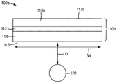
도 1a는 활성층(112), 활성층(112) 반대편의 제1 외부 표면(115)을 갖는 제1 외부 층(114), 활성층(112) 반대편의 제2 외부 표면(117)을 갖는 제2 층(116)을 갖는 스위칭가능 확산기(110)를 포함하는 광학 시스템의 개략적인 단면도이다. 제2 외부 표면(117)은 광 방향전환 구조체들(118)을 포함한다. 활성층(112)은 제1 외부 층(114)과 제2 외부 층(116) 사이에 배치된다. 활성층(112)은 액정 층일 수 있고 스멕틱 A 액정을 포함할 수 있다. 제1 및 제2 외부 층들(114, 116)은 중합체 층들일 수 있거나 유리 층들일 수 있거나, 또는 외부 층들 중 하나가 유리 층이면서 다른 하나는 중합체 층일 수 있다. 광학 시스템(100)은 스위칭가능 확산기(110)와 광학적으로 연결되는 조명 컴포넌트(120)를 추가로 포함한다. 조명 컴포넌트(120)는 예를 들어, 하나 이상의 발광 다이오드(LED) 또는 냉음극 형광 램프(CCFL)와 같은 임의의 유형의 조명 컴포넌트일 수 있다. 본 명세서의 광학 시스템들 중 임의의 것에서 사용되는 조명 컴포넌트들은 도광체를 포함할 수 있거나 포함하지 않을 수 있으며, 광을 원하는 방향으로 지향시키도록 배치된 반사기들을 포함할 수 있거나 포함하지 않을 수 있다. 일부 실시예들에서, 조명 컴포넌트는 LED와 같은 광원과 함께, 도광체의 에지 내로 광을 주입하도록 배치되는 도광체를 포함한다. 적합한 도광체가 미국 특허 출원 공개 제2010/0014027호(리(Li) 등) 및 미국 특허 제7,532,800호(이이무라(Iimura)) 및 제7,699,516호(리(Lee))에 기술되어 있다. 스위칭가능 확산기(110)는 제1 탁도에 의해 특징지어지는 제1 상태, 및 제1 탁도와 상이한 제2 탁도에 의해 특징지어지는 제2 상태를 갖는다.1A shows a
도시된 실시예에서, 제1 외부 표면(115)은 비구조화되어 있지만 제2 외부 표면(117)은 구조화되어 있다. 다른 실시예들에서, 제1 외부 표면(115)은 구조화되어 있지만 제2 외부 표면(117)은 비구조화되어 있다. 또 다른 실시예들에서, 제1 및 제2 외부 표면들(115, 117)은 둘 다 구조화되어 있다. 제2 외부 표면(117)에 의해 제공된 구조체들은 적어도 하나의 방향에서 광학 시스템의 광출력의 반치전폭(FWHM)을, 광 방향전환 구조체들을 포함하지 않는 다른 점에서 동등한 광학 시스템의 광출력의 FWHM에 비해 증가시키도록 구성된 광 방향전환 구조체들(118)이다. 예를 들어, 광 방향전환 구조체들(118)은 적어도 5도, 또는 적어도 7도, 또는 적어도 10도, 또는 적어도 15도, 또는 적어도 20도만큼 FWHM을 증가시킬 수 있고, 스위칭가능 확산기가 가장 낮은 탁도 상태일 수 있는 제1 상태에 있을 때 적어도 하나의 방향을 따라 45도만큼, 또는 60도만큼, 또는 90도만큼, 또는 120도만큼, 또는 150도만큼 FWHM을 증가시킬 수 있다.In the illustrated embodiment, the first
본 명세서의 광학 시스템들 중 임의의 것에서, 광 방향전환 구조체들의 유효성을 최대화하기 위해 공기 계면이 광 방향전환 구조체들에 존재하도록 광 방향전환 구조체들을 배치하는 것이 바람직할 수 있다. 예를 들어, 공기 계면은 제2 외부 표면(117)에 존재할 수 있다. 다른 실시예들에서, 저-굴절률 재료의 층이 광 방향전환 구조체들 상에 또는 그 위에 배치된다. 본 명세서에 사용된 바와 같이, "저-굴절률" 재료는 약 1.45 이하의 굴절률을 갖는 재료를 말한다. 본 명세서에 사용된 바와 같이, 다르게 규정되지 않는 한, "굴절률"은 25℃에서 589 nm(나트륨 D 선(sodium D line))의 파장을 갖는 광에 대한 굴절률을 말한다. 일부 실시예들에서, 저-굴절률 재료는 약 1.45 이하 또는 약 1.42 이하 또는 약 1.41 이하 또는 약 1.39 이하의 굴절률을 갖는 광학적으로 투명한 접착제이다. 적합한 저-굴절률의 광학적 투명 접착제는 1.315 내지 1.44의 범위의, 제조자에 의해 인용된 굴절률을 갖는 놀랜드 광학 접착제(Norland Optical Adhesive) 1315, 132, 138, 142 및 144(미국 뉴저지주 크랜버리 소재의 놀랜드 프로덕츠(Norland Products)로부터 입수가능함)를 포함한다. 일부 실시예들에서, 저-굴절률 층은 약 1.3 미만 또는 약 1.2 미만 또는 심지어 약 1.15 미만의 굴절률을 갖는 초저-굴절률(ultra low-index, ULI) 층이며, 약 1.05만큼 낮을 수 있다. 적합한 ULI 재료는 미국 특허 출원 공개 제2012/0038990호(하오(Hao) 등)에 기술된 것과 같은 나노공극형(nanovoided) 재료를 포함한다.In any of the optical systems herein, it may be desirable to arrange the light redirecting structures such that the air interface is present in the light redirecting structures in order to maximize the effectiveness of the light redirecting structures. For example, the air interface may be present at the second
스위칭가능 확산기(110)는 조명 컴포넌트(120)로부터 거리(D)만큼 이격되어 있다. 스위칭가능 확산기(110)는 폭(W)을 갖는다. 거리(D)는 폭(W)의 약 20배 미만, 또는 약 10배 미만, 또는 약 5배 미만일 수 있고, 실질적으로 0일 수 있다.The
광학 시스템(100)은 스위칭가능 확산기(110)의 상태를 변화시키도록 구성된 확산기 제어기를 추가로 포함할 수 있다. 대안적으로, 확산기 제어기는 광학 시스템(100)의 외부에 배치될 수 있다. 확산기 제어기는 예를 들어, 센서 입력에 응답하여 또는 스위치의 설정에 기초하여 스위칭가능 확산기(110)의 상태를 변화시킬 수 있다. 확산기 제어기는 유선 또는 무선 연결을 통해 확산기 제어 신호를 스위칭가능 확산기(110)에 제공할 수 있다.The
도 1b는, 제2 외부 층(116)의 광 방향전환 구조체들(118)이 존재하지 않고 대신에 광학 시스템(100b)이 비구조화된 제2 외부 표면(117b)을 갖는 제2 외부 층(116b)을 갖는 스위칭가능 확산기(110b)를 포함한다는 점을 제외하고는, 광학 시스템(100)과 다른 점에서 동등한 광학 시스템(100b)의 개략적인 단면도이다. 제2 외부 층(116b)은 스위칭가능 확산기(110)의 제2 외부 층(116)과 다른 점에서 동등하고, 스위칭가능 확산기(110b)는 스위칭가능 확산기(110)와 다른 점에서 동등하다. 광학 시스템(100)은 적어도 하나의 축을 따라 그리고 스위칭가능 확산기의 적어도 하나의 상태에 대해, 다른 곳에서 기술된 범위들 중 임의의 범위 내의 양만큼 광학 시스템(100b)의 대응하는 FWHM보다 큰 FWHM을 가질 수 있다. 예를 들어, 스위칭가능 확산기(110)가 제1 상태에 있을 때 제1 축을 따르는 시스템(100)의 FWHM은 스위칭가능 확산기(110b)가 대응하는 제1 상태에 있을 때 제1 축을 따르는 시스템(100b)의 FWHM보다 5도 내지 150도의 범위 내의 양만큼 더 클 수 있다.Figure lb illustrates a second
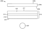
도 2a는 활성층(212), 활성층(212) 반대편의 제1 외부 표면(215)을 갖는 제1 외부 층(214), 활성층(212) 반대편의 제2 외부 표면(217)을 갖는 제2 층(216)을 갖는 스위칭가능 확산기(210)를 포함하는 광학 시스템(200)의 개략적인 단면도이다. 활성층(212)은 제1 외부 층(214)과 제2 외부 층(216) 사이에 배치된다. 활성층(212)은 액정 층일 수 있고 스멕틱 A 액정을 포함할 수 있다. 제1 및 제2 외부 층들(214, 216)은 중합체 층들일 수 있거나 유리 층들일 수 있거나, 또는 외부 층들 중 하나가 유리 층이면서 다른 하나는 중합체 층일 수 있다. 광학 시스템(200)은 스위칭가능 확산기(210)와 광학적으로 연결되고 제1 외부 표면(215)을 향하는 광출력 방향을 갖는 조명 컴포넌트(220)를 추가로 포함한다. 조명 컴포넌트(220)는 예를 들어, 하나 이상의 LED 또는 CCFL과 같은 임의의 유형의 조명 컴포넌트일 수 있다. 도시된 실시예에서, 제1 및 제2 외부 표면들(215, 217)은 비구조화되어 있다. 스위칭가능 확산기(210)는 제1 탁도에 의해 특징지어지는 제1 상태, 및 제1 탁도와 상이한 제2 탁도에 의해 특징지어지는 제2 상태를 갖는다.2A shows a
광학 시스템(200)은 대향하는 (광 방향전환 구조체들(233)을 포함하는) 제1 외부 표면(232) 및 (광 방향전환 구조체들(235)을 포함하는) 제2 외부 표면(234)을 갖는 저-흡수 광학 컴포넌트(230)를 추가로 포함한다. 저-흡수 광학 컴포넌트(230)는 조명 컴포넌트(220) 및 스위칭가능 확산기(210)와 광학적으로 연결된다. 도시된 실시예에서, 제1 및 제2 외부 표면들(232, 234)은 둘 다 광 방향전환 구조체들을 포함한다. 다른 실시예들에서, 제1 및 제2 외부 표면들(232, 234) 중 하나는 비구조화되어 있다. 또 다른 실시예들에서, 저-흡수 광학 컴포넌트(230)의 제1 및 제2 외부 표면들(232, 234) 및 스위칭가능 확산기(210)의 제1 및 제2 외부 표면들(215, 217) 중 1개, 2개, 3개 또는 4개는 광 방향전환 구조체들을 포함한다. 저-흡수 광학 컴포넌트(230)는 중합체 또는 유리 층으로 형성될 수 있다.
도 2b는, 저-흡수 광학 컴포넌트(230)가 비구조화된 외부 표면들(232b, 234b)을 포함하는 저-흡수 광학 컴포넌트(230b)로 대체된 것을 제외하고는, 광학 시스템(200)과 다른 점에서 동등한 광학 시스템(200b)을 도시한다. 다시 말해서, 광학 시스템(200b)은, 광 방향전환 구조체들(233, 235)이 광학 시스템(200b)에 포함되지 않는다는 점을 제외하고는, 광학 시스템(200)과 다른 점에서 동등하다.2B shows an alternative embodiment of the
외부 표면들(232, 234)에 의해 각각 제공되는 광 방향전환 구조체들(233, 235)은 적어도 하나의 방향에서 광학 시스템의 광출력의 반치전폭(FWHM)을, 광 방향전환 구조체들(233, 235)을 포함하지 않는 다른 점에서 동등한 광학 시스템(200b)의 광출력의 FWHM에 비해 증가시키도록 구성된다. 예를 들어, 광 방향전환 구조체들(233, 235)은 적어도 5도, 또는 적어도 7도, 또는 적어도 10도, 또는 적어도 15도, 또는 적어도 약 20도만큼 FWHM을 증가시킬 수 있고, 스위칭가능 확산기(210)가 가장 낮은 탁도 상태일 수 있는 제1 상태에 있을 때 적어도 하나의 방향을 따라 45도만큼, 또는 60도만큼, 또는 90도만큼, 또는 120도만큼, 또는 150도만큼 FWHM을 증가시킬 수 있다. 공기 인터페이스 또는 저-굴절률 층이 제1 및 제2 외부 표면들(232, 234)에 존재할 수 있다.The optical
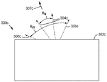
도 3a는 출력 표면(302)을 갖는 광학 시스템(300)의 개략적인 측면도이다. 광학 시스템(100) 또는 광학 시스템(200)에 대응할 수 있는 광학 시스템(300)은 스위칭가능 확산기를 포함하며 저-흡수 광학 컴포넌트를 포함할 수 있고, 스위칭가능 확산기 및/또는 저-흡수 광학 컴포넌트의 적어도 하나의 외부 표면은 광 방향전환 구조체들을 포함한다. 스위칭가능 확산기가 가장 낮은 탁도 상태일 수 있는 제1 상태에 있을 때, 광학 시스템(300)의 광출력은 θN의 반치전폭을 갖는 비교적 좁은 출력 분포(304)를 갖는다. 스위칭가능 확산기가 높은 탁도 상태일 수 있는 제2 상태에 있을 때, 광학 시스템(300)의 광출력은 θW의 반치전폭을 갖는 비교적 넓은 출력 분포(306)를 갖는다. 광학 시스템(300)의 평균 광출력(307)의 방향은 출력 표면(302)에 실질적으로 수직이다.3A is a schematic side view of an
도 3b는 출력 표면(302b)을 갖는 광학 시스템(300b)의 개략적인 측면도이다. 광학 시스템(300b)은, 스위칭가능 확산기 및 저-흡수 광학 컴포넌트(존재하는 경우)의 각각의 주 표면이 실질적으로 편평한 표면들로 대체된다는 점을 제외하고는, 광학 시스템(300)과 동등하다. 즉, 광 방향전환 구조체들은 제거된다. 스위칭가능 확산기가 가장 낮은 탁도 상태일 수 있는 제1 상태에 있을 때, 광학 시스템(300b)의 광출력은 θ0 N의 반치전폭을 갖는 비교적 좁은 출력 분포(304b)를 갖는다. 스위칭가능 확산기가 높은 탁도 상태일 수 있는 제2 상태에 있을 때, 광학 시스템(300b)의 광출력은 θ0 W의 반치전폭을 갖는 비교적 넓은 출력 분포(306b)를 갖는다. 일부 실시예들에서, θN은 θ0 N보다 적어도 5도, 또는 적어도 7도, 또는 적어도 10도, 또는 적어도 15도, 또는 적어도 20도만큼 더 크고, θN는 θ0 N보다 45도만큼, 또는 60도만큼, 또는 90도만큼, 또는 120도만큼, 또는 150도만큼, 또는 심지어 175도만큼 더 클 수 있다. 일부 실시예들에서, θW은 θ0 W보다 적어도 5도, 또는 적어도 7도, 또는 적어도 10도, 또는 적어도 15도, 또는 적어도 20도만큼 더 크고,θW는 θ0 W보다 45도만큼, 또는 60도만큼, 또는 90도만큼, 또는 120도만큼, 또는 150도만큼, 또는 심지어 175도만큼 더 클 수 있다. 광학 시스템(300b)의 평균 광출력(307b)의 방향은 출력 표면(302b)에 실질적으로 수직이고 광학 시스템(300)의 평균 광출력(307)의 방향과 실질적으로 동일하다.3B is a schematic side view of an
본 명세서의 광학 시스템들은 광출력의 FWHM 및 광출력의 평균 방향 둘 모두를 변화시키는 광 방향전환 구조체들을 포함할 수 있다. 도 3c는 출력 표면(302c)을 갖는 광학 시스템(300c)의 개략적인 측면도이다. 광학 시스템(300c)은 스위칭가능 확산기를 포함하며 저-흡수 광학 컴포넌트를 포함할 수 있으며, 스위칭가능 확산기 및/또는 저-흡수 광학 컴포넌트의 적어도 하나의 외부 표면은 광 방향전환 구조체들을 포함한다. 광학 시스템(300c)은, 광 방향전환 구조체들의 배열을 제외하고는 그리고/또는 스위칭가능 확산기 및/또는 저-흡수 광학 컴포넌트의 배치 또는 배열을 제외하고는, 광학 시스템(300)과 동등할 수 있다. 광 방향전환 구조체들이 없다는 것을 제외하고는 광학 시스템(300c)과 다른 점에서 동등한 광학 시스템의 출력은 광학 시스템(300b)과 동일한 출력 분포를 가질 수 있다. 스위칭가능 확산기가 가장 낮은 탁도 상태일 수 있는 제1 상태에 있을 때, 광학 시스템(300c)의 광출력은 θN의 반치전폭을 갖는 비교적 좁은 출력 분포(304c)를 갖는다. 스위칭가능 확산기가 높은 탁도 상태일 수 있는 제2 상태에 있을 때, 광학 시스템(300c)의 광출력은 θW의 반치전폭을 갖는 비교적 넓은 출력 분포(306c)를 갖는다. 광학 시스템(300c)의 평균 광출력(307c)의 방향은 광학 시스템(300b)의 것과 상이하다.The optical systems herein may include light direction switching structures that change both the FWHM of the light output and the average direction of the light output. 3C is a schematic side view of an
일부 실시예들에서, 평균 광출력 방향은 스위칭가능 확산기의 상태에 의존한다. 예를 들어, 스위칭가능 확산기가 광학 시스템의 광축에 대하여 소정 각도로 배치되는 경우, 스위칭가능 확산기가 높은 탁도 상태에 있을 때 평균 광출력 방향은 스위칭가능 확산기가 낮은 탁도 상태에 있을 때 평균 광출력 방향과 상이할 수 있다. 일부 실시예들에서, 스위칭가능 확산기가 제1 상태에 있을 때 광학 시스템의 광출력의 평균 방향은 스위칭가능 확산기가 제1 상태에 있을 때 다른 점에서 동등한 광학 시스템의 광출력의 평균 방향과 동일하다. 일부 실시예들에서, 스위칭가능 확산기가 제1 상태에 있을 때 광학 시스템의 광출력의 평균 방향은 스위칭가능 확산기가 제1 상태에 있을 때 다른 점에서 동등한 광학 시스템의 광출력의 평균 방향과 상이하다. 광출력 방향들은 적어도 5도 또는 적어도 10도만큼 상이할 수도 있고, 60도만큼, 80도만큼 상이할 수 있다. 제1 상태는 스위칭가능 확산기의 가장 낮은 탁도 상태(예를 들면, 실질적으로 투명 상태)일 수 있다.In some embodiments, the average light output direction depends on the state of the switchable diffuser. For example, when the switchable diffuser is positioned at an angle relative to the optical axis of the optical system, the average light output direction when the switchable diffuser is in a high turbidity state is the average light output direction when the switchable diffuser is in a low turbidity state Lt; / RTI > In some embodiments, the average direction of the optical output of the optical system when the switchable diffuser is in the first state is equal to the average direction of the optical output of the equivalent optical system otherwise at the time the switchable diffuser is in the first state . In some embodiments, the average direction of the optical output of the optical system when the switchable diffuser is in the first state is different from the average direction of the optical output of the equivalent optical system in other respects when the switchable diffuser is in the first state . The light output directions may differ by at least 5 degrees or at least 10 degrees, and may be as much as 60 degrees and as many as 80 degrees. The first state may be the lowest turbidity state of the switchable diffuser (e.g., substantially transparent).
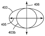
본 명세서의 광학 시스템들의 광출력은 축 대칭일 수 있거나 축 비대칭일 수 있다. 광 방향전환 구조체들은 하나 또는 2개의 비-동일 선상의(non-collinear)(예를 들어, 직교) 축들에서의 FWHM을 증가시킬 수 있다. 도 4a는, 비-동일 선상의 제2 축(406)을 따라서가 아닌 제1 축(405)을 따라서 FWHM을 증가시키도록 구성된 광 방향전환 구조체들을 갖는 광학 시스템으로부터의 축 비대칭 FWHM 출력 분포(403)의 평면도를 개략적으로 도시한다. 광 방향전환 구조체들을 갖지 않는 다른 점에서 동등한 광학 시스템은 축 대칭 FWHM 출력 분포(403b)를 생성한다. 도 4b는, 제1 축(405)을 따라서 그리고 비-동일 선상의 제2 축(406)을 따라서 FWHM을 증가시키도록 구성된 광 방향전환 구조체들을 갖는 광학 시스템으로부터의 축 대칭 FWHM 출력 분포(403c)의 평면도를 개략적으로 도시한다. 다른 점에서 동등한 광학은 FWHM 출력 분포(403b)를 생성한다.The optical power of the optical systems herein may be axisymmetric or asymmetrical. The light redirecting structures may increase the FWHM on one or two non-collinear (e.g., quadrature) axes. 4A shows an axial asymmetric
도 5a는 활성층(512), 활성층(512) 반대편의 제1 외부 표면(515)을 갖는 제1 외부 층(514), 활성층(512) 반대편의 제2 외부 표면(517)을 갖는 제2 층(516)을 갖는 스위칭가능 확산기(510)를 포함하는 광학 시스템(500)의 개략적인 단면도이다. 활성층(512)은 제1 외부 층(514)과 제2 외부 층(516) 사이에 배치된다. 활성층(512)은 액정 층일 수 있고 스멕틱 A 액정을 포함할 수 있다. 제1 및 제2 외부 층들(514, 516)은 중합체 층들일 수 있거나 유리 층들일 수 있거나, 또는 외부 층들 중 하나가 유리 층이면서 다른 하나는 중합체 층일 수 있다. 광학 시스템(500)은 제1 외부 표면(515)을 향하는 조명 컴포넌트(520)를 추가로 포함한다. 조명 컴포넌트(520)는 광원(522) 및 도광체(524)를 포함한다. 광원(522)은 예를 들어, 하나 이상의 LED 또는 CCFL과 같은 임의의 유형의 광원일 수 있다. 스위칭가능 확산기(510)의 반대편으로 도광체(524)를 나가는 광을 다시 도광체(524)로 지향시키기 위해, 반사기(526)가 도광체(524)에 인접하게 포함될 수 있다. 광학 시스템(500)은 확산기 상태 데이터 및 확산기 제어 신호를 확산기 데이터 채널(542) 상에서 스위칭가능 확산기(510)에 제공하는 확산기 제어기(540)를 추가로 포함한다.5A shows a
제2 외부 표면(517)은 다른 곳에서 설명된 바와 같이 적어도 하나의 축을 따라 광출력의 FWHM을 증가시키도록 구성된 광 방향전환 구조체들(518)을 포함한다.The second
광학 시스템(500)은 대향하는 제1 외부 표면(532) 및 제2 외부 표면(534)을 갖는 저-흡수 광학 컴포넌트(530)를 추가로 포함한다. 도시된 실시예에서, 제1 외부 표면(532)은 광 방향전환 구조체들(533)을 포함하는 반면에, 제2 외부 표면(534)은 실질적으로 비구조화되어 있다. 저-흡수 광학 컴포넌트(530), 스위칭가능 확산기(510) 및 조명 컴포넌트(520)는 서로 광학적으로 연결된다. 광 방향전환 구조체들(533)은 광학 시스템(500)으로부터의 광의 평균 출력 방향을 변화시키도록 구성된 프리즘 요소들일 수 있다.The
도 5b는, 제2 외부 층(516)의 광 방향전환 구조체들(518)이 포함되지 않고 그 대신에 스위칭가능 확산기(510b)의 제2 외부 층(516b)의 제2 외부 표면(517b)이 비구조화되어 있는 점을 제외하고는, 광학 시스템(500)과 다른 점에서 동등한 광학 시스템(500b)의 개략적인 단면도이다. 일부 실시예들에서, 광학 시스템(500)의 광출력의 FWHM은 광학 시스템(500b)의 광출력의 FWHM보다 적어도 5도, 또는 적어도 7도, 또는 적어도 10도, 또는 적어도 15도, 또는 적어도 20도만큼 더 크고, 스위칭가능 확산기의 적어도 하나의 상태에 대해 적어도 하나의 축을 따라 45도만큼, 또는 60도만큼, 또는 90도만큼, 또는 120도만큼, 또는 150도만큼 더 클 수 있다.Figure 5b illustrates that the light
도 5c는, 제2 외부 층(516)의 광 방향전환 구조체들(518) 및 저-흡수 광학 컴포넌트(530)의 광 방향전환 구조체들(533)이 포함되지 않는다는 점을 제외하고는, 광학 시스템(500)과 다른 점에서 동등한 광학 시스템(500c)의 개략적인 단면도이다. 광학 시스템(500c)의 스위칭가능 확산기(510b)는 광학 시스템(500b)의 것과 동등하다. 광학 시스템(500)의 저-흡수 광학 컴포넌트(530)는 광학 시스템(500c) 내의 저-흡수 광학 컴포넌트(530c)로 대체된다. 저-흡수 광학 컴포넌트(530c)는 대향하는 제1 및 제2 외부 표면들(532c, 534c)을 포함한다. 저-흡수 광학 컴포넌트(530c)는 제1 외부 표면(532c)이 실질적으로 비구조화되어 있다는 점을 제외하고는 저-흡수 광학 컴포넌트(530)와 동등하다. 일부 실시예들에서, 광학 시스템(500)의 광출력의 FWHM은 광학 시스템(500c)의 광출력의 FWHM보다 적어도 5도, 또는 적어도 7도, 또는 적어도 10도, 또는 적어도 15도, 또는 적어도 20도만큼 더 크고, 스위칭가능 확산기의 적어도 하나의 상태에 대해 적어도 하나의 축을 따라 45도만큼, 또는 60도만큼, 또는 90도만큼, 또는 120도만큼, 또는 150도만큼 더 클 수 있다.5C shows the optical system of the present invention with the exception that the optical
본 명세서에서 기술된 광학 시스템들에서, 스위칭가능 확산기 및/또는 저-흡수 광학 컴포넌트의 대향하는 주 표면들 중 임의의 것은, 적어도 일부가 광학 시스템의 광출력의 FWHM을 증가시키는 것에 기여하는 광 방향전환 구조체들을 포함할 수 있다. 일부 실시예들에서, 하나 이상의 표면은 광학 시스템의 광출력의 FWHM을 증가시키는 것에 추가하여 또는 대신에 광출력의 방향을 변화시키도록 구성된 광 방향전환 요소들을 포함한다.In the optical systems described herein, any of the opposing major surfaces of the switchable diffuser and / or the low-absorption optical component is at least partially oriented in the light direction that contributes to increasing the FWHM of the optical output of the optical system Conversion structures. In some embodiments, the at least one surface comprises light direction switching elements configured to change the direction of light output in addition to or instead of increasing the FWHM of the light output of the optical system.
도 6a는 활성층(612), 활성층(612) 반대편의 제1 외부 표면(615)을 갖는 제1 외부 층(614), 활성층(612) 반대편의 제2 외부 표면(617)을 갖는 제2 층(616)을 갖는 스위칭가능 확산기(610)를 포함하는 광학 시스템(600)의 개략적인 단면도이다. 활성층(612)은 제1 외부 층(614)과 제2 외부 층(616) 사이에 배치된다. 활성층(612)은 액정 층일 수 있고 스멕틱 A 액정을 포함할 수 있다. 제1 및 제2 외부 층들(614, 616)은 중합체 층들일 수 있거나 유리 층들일 수 있거나, 또는 외부 층들 중 하나가 유리 층이면서 다른 하나는 중합체 층일 수 있다. 광학 시스템(600)은 제1 외부 표면(615)을 향하는 조명 컴포넌트(620)를 추가로 포함한다. 조명 컴포넌트(620)는 광원(622) 및 도광체(624)를 포함한다. 광원(622)은 예를 들어, 하나 이상의 LED 또는 CCFL과 같은 임의의 유형의 광원일 수 있다. 스위칭가능 확산기(610)의 반대편으로 도광체(624)를 나가는 광을 다시 도광체(624)로 지향시키기 위해, 반사기(626)가 도광체(624)에 인접하게 포함될 수 있다. 광학 시스템(600)은 확산기 상태 데이터 및 확산기 제어 신호를 확산기 데이터 채널(642) 상에서 스위칭가능 확산기(610)에 제공하는 확산기 제어기(640)를 추가로 포함한다.6A shows a
제2 외부 표면(617)은 다른 곳에서 설명된 바와 같이 적어도 하나의 축을 따라 광출력의 FWHM을 증가시키도록 구성된 광 방향전환 구조체들(618)을 포함한다. 광학 시스템(600)은 대향하는 제1 외부 표면(632) 및 제2 외부 표면(634)을 갖는 저-흡수 광학 컴포넌트(630)를 추가로 포함한다. 도시된 실시예에서, 제1 외부 표면(632)은 광 방향전환 구조체들의 제1 세트(633)를 포함하는 반면, 제2 외부 표면(634)은 광 방향전환 구조체들의 제2 세트(635)를 포함한다. 광 방향전환 구조체들의 제1 세트(633)는 광학 시스템(600)의 평균 광출력 방향을 변화시키도록 구성되는 반면, 광 방향전환 구조체들의 제2 세트(635)는 다른 곳에서 설명된 바와 같이 적어도 하나의 축을 따라 광출력의 FWHM을 증가시키도록 구성된다. 저-흡수 광학 컴포넌트(630), 스위칭가능 확산기(610) 및 조명 컴포넌트(620)는 서로 광학적으로 연결된다.The second
도 6b는, 스위칭가능 확산기(610)의 광 방향전환 구조체들(618)이 포함되지 않고 저-흡수 광학 컴포넌트(630)의 광 방향전환 구조체들의 제1 및 제2 세트(633, 635)가 포함되지 않는다는 점을 제외하고는, 광학 시스템(600)과 동등한 광학 시스템(600b)의 개략적인 단면도이다. 그 대신에, 스위칭가능 확산기(610)는, 제2 층(616)이 비구조화된 제2 외부 표면(617b)을 갖는 제2 층(616b)으로 대체된 것을 제외하고는 스위칭가능 확산기(610)와 동등한 스위칭가능 확산기(610b)로 대체되었고, 저-흡수 광학 컴포넌트(630)는, 제1 및 제2 외부 표면들(632, 634)이 둘 다 비구조화된 제1 및 제2 외부 표면들(632b, 634b)로 대체된 것을 제외하고는 저-흡수 광학 컴포넌트(630)와 동등한 저-흡수 광학 컴포넌트(630b)로 대체되었다.Figure 6b illustrates that the first and second sets of light redirecting
일부 실시예들에서, 광학 시스템(600)의 광출력의 FWHM은 광학 시스템(600b)의 광출력의 FWHM보다 적어도 5도, 또는 적어도 7도, 또는 적어도 10도, 또는 적어도 15도, 또는 적어도 20도만큼 더 크고, 스위칭가능 확산기의 적어도 하나의 상태에 대해 적어도 하나의 축을 따라 45도만큼, 또는 60도만큼, 또는 90도만큼, 또는 120도만큼, 또는 150도만큼 더 클 수 있다.In some embodiments, the FWHM of the optical output of
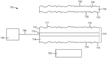
도 7a는 활성층(712), 활성층(712) 반대편의 제1 외부 표면(715)을 갖는 제1 외부 층(714), 활성층(712) 반대편의 제2 외부 표면(717)을 갖는 제2 층(716)을 갖는 스위칭가능 확산기(710)를 포함하는 광학 시스템(700)의 개략적인 단면도이다. 제1 외부 표면(715)은 광 방향전환 구조체들(719)을 포함하고 제2 외부 표면(717)은 광 방향전환 구조체들(718)을 포함한다. 활성층(712)은 제1 외부 층(714)과 제2 외부 층(716) 사이에 배치되고 액정 층일 수 있고 스멕틱 A 액정을 포함할 수 있다. 제1 및 제2 외부 층들(714, 716)은 중합체 층들일 수 있거나 유리 층들일 수 있거나, 또는 외부 층들 중 하나가 유리 층이면서 다른 하나는 중합체 층일 수 있다. 광학 시스템(700)은 도 7a에 개략적으로 도시된, 제1 외부 표면(715)을 향하는 조명 컴포넌트(720)를 추가로 포함한다. 조명 컴포넌트(720)는 하나 이상의 LED를 포함할 수 있고, 반사기를 포함하거나 포함하지 않을 수 있으며, 도광체를 포함하거나 포함하지 않을 수 있다. 광학 시스템(700)은 확산기 상태 데이터 및 확산기 제어 신호를 확산기 데이터 채널(742) 상에서 스위칭가능 확산기(710)에 제공하는 확산기 제어기(740)를 추가로 포함한다.7A shows a
광학 시스템(700)은 대향하는 제1 외부 표면(732) 및 제2 외부 표면(734)을 갖는 저-흡수 광학 컴포넌트(730)를 추가로 포함한다. 제1 외부 표면(732)은 광 방향전환 구조체들(733)을 포함하고 제2 외부 표면(734)은 광 방향전환 구조체들(735)을 포함한다. 광 방향전환 구조체들(719, 718, 733, 735)은 다른 곳에서 설명된 바와 같이 적어도 하나의 축을 따라 광출력의 FWHM을 증가시키도록 구성된다. 저-흡수 광학 컴포넌트(730), 스위칭가능 확산기(710) 및 조명 컴포넌트(720)는 서로 광학적으로 연결된다.
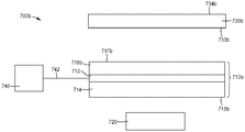
도 7b는, 스위칭가능 확산기(710)의 광 방향전환 구조체들(718, 719)이 포함되지 않고 저-흡수 광학 컴포넌트(730)의 광 방향전환 구조체들(733, 735)이 포함되지 않는다는 점을 제외하고는, 광학 시스템(700)과 동등한 광학 시스템(700b)의 개략적인 단면도이다. 스위칭가능 확산기(710)는, 제1 층(714)이 비구조화된 제1 외부 표면(714b)을 갖는 제1 층(714b)으로 대체되었고 제2 층(716)이 비구조화된 제2 외부 표면(717b)을 갖는 제2 층(716b)으로 대체된 점을 제외하고는, 스위칭가능 확산기(710)와 동등한 스위칭가능 확산기(710b)로 대체되었다. 유사하게, 저-흡수 광학 컴포넌트(730)는, 제1 및 제2 외부 표면들(732, 734)이 둘 다 비구조화된 제1 및 제2 외부 표면들(732b, 734b)로 대체된 점을 제외하고는, 저-흡수 광학 컴포넌트(730)와 동등한 저-흡수 광학 컴포넌트(730b)로 대체되었다.7B does not include the light
일부 실시예들에서, 광학 시스템(700)의 광출력의 FWHM은 광학 시스템(700b)의 광출력의 FWHM보다 적어도 5도, 또는 적어도 7도, 또는 적어도 10도, 또는 적어도 15도, 또는 적어도 20도만큼 더 크고, 스위칭가능 확산기의 적어도 하나의 상태(예를 들어, 실질적으로 투명 상태 또는 가장 낮은 탁도 상태일 수 있는 제1 상태)에 대해 적어도 하나의 축을 따라 45도만큼, 또는 60도만큼, 또는 90도만큼, 또는 120도만큼, 또는 150도만큼 더 클 수 있다.In some embodiments, the FWHM of the optical output of
본 명세서의 광학 시스템들은 조명 응용, 디스플레이, 및 표지판을 포함하는 많은 상이한 응용들에서 사용될 수 있다. 일부 경우들에서, 본 명세서의 광학 시스템을 포함하는 조명기구가 제공된다. 일부 경우들에서, 본 명세서의 광학 시스템을 포함하고 디스플레이 패널을 포함하는 디스플레이가 제공된다. 디스플레이 패널은 임의의 유형의 디스플레이 패널일 수 있으며; 예를 들어, 액정 디스플레이(LCD) 패널일 수 있다. 일부 경우들에서, 본 명세서의 광학 시스템을 포함하는 표지판이 제공된다. 표지판은 LCD 패널을 추가로 포함할 수 있다. 조명 컴포넌트, 스위칭가능 확산기, 및 저-흡수 광학 컴포넌트들(포함되는 경우)의 많은 상이한 배열들이 가능하다. 일부 예시적인 구성들이 도 8 및 도 9에 도시되어 있다.The optical systems herein may be used in many different applications, including lighting applications, displays, and signs. In some cases, a luminaire comprising the optical system of the present disclosure is provided. In some cases, a display comprising the optical system of the present disclosure and including a display panel is provided. The display panel may be any type of display panel; For example, a liquid crystal display (LCD) panel. In some cases, a sign including the optical system of the present disclosure is provided. The sign may further include an LCD panel. Many different arrangements of illumination components, switchable diffusers, and low-absorption optical components (if included) are possible. Some exemplary configurations are shown in Figs. 8 and 9. Fig.
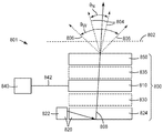
도 8은 광학 시스템(800), 디스플레이 패널(850) 및 출력 표면(802)을 포함하는 광학 시스템(801)의 개략적인 측면도이다. 광학 시스템(801)은 협시야각 출력(804) 또는 광시야각 출력(806)을 가질 수 있다. 광학 시스템(800)은 광학 경로(808)를 갖는 광을 생성할 수 있는 조명 컴포넌트(820)를 포함한다. 광학 시스템(800)은 조명 컴포넌트(820)와 광학적으로 연결되는 전기적 스위칭가능 확산기(810)를 포함하고, 확산기 상태 데이터 및 확산기 제어 신호를 확산기 데이터 채널(842) 상에서 스위칭가능 확산기(810)에 제공하는 확산기 제어기(840)를 포함한다. 조명 컴포넌트(820)는 광원(822) 및 도광체(824)를 포함한다. 조명 컴포넌트(820)는 출력 표면(802) 반대편에서 스위칭가능 확산기(810)에 인접하게 배치된다. 광학 시스템(800)은 또한 선택적인 광학 컴포넌트(830) 및 선택적인 광학 컴포넌트(835)를 포함할 수 있다. 선택적인 광학 컴포넌트들(830, 835)은, 포함되는 경우, 조명 컴포넌트(822)와 광학적으로 연결되고 스위칭가능 확산기(810)와 광학적으로 연결된다. 선택적인 광학 컴포넌트(835)는 조명 컴포넌트(820) 반대편에서 스위칭가능 확산기(810)에 인접한다. 선택적인 광학 컴포넌트(830)는 출력 표면(802) 반대편에서 스위칭가능 확산기(810)에 인접한다. 선택적인 광학 컴포넌트(830, 835) 중 어느 하나 또는 둘 모두는 단일 필름일 수 있거나, 또는 광학적으로 투명한 접착제로 함께 라미네이팅될 수 있거나 층들 사이에 공기 간극이 있는 상태로 함께 적층될 수 있는 필름들의 스택(stack)일 수 있다. 일부 실시예들에서, 선택적인 광학 컴포넌트(830)가 포함되며 저-굴절률 층이다. 일부 실시예들에서, 선택적인 광학 컴포넌트(830)가 포함되지 않아, 공기 간극만이 스위칭가능 확산기(810)와 도광체(824)를 분리시킨다. 일부 실시예들에서, 선택적인 광학 컴포넌트들(830, 835) 중 어느 하나 또는 둘 모두는 추가의 확산기들이고 표면 확산기들일 수 있거나 추가의 전기적 스위칭가능 확산기들일 수 있다.8 is a schematic side view of an
일부 실시예들에서, 스위칭가능 확산기(810)가 제1 상태에 있을 때, 광학 시스템(801)은 특성 시야각(θN)을 갖는 협시야각 출력(804)을 생성하고, 스위칭가능 확산기(810)가 제2 상태에 있을 때, 광학 시스템(801)은 특성 시야각(θW)을 갖는 광시야각 출력(806)을 생성한다. 제1 상태는 스위칭가능 확산기의 가장 투명한 상태일 수 있고 제2 상태는 높은 탁도 상태일 수 있다. 특성 시야각은 강도의 출력 각도 분포의 면에서 반치전폭으로 정의될 수 있다. 일부 실시예들에서, 광학 시스템(800)은 제1 방향을 따라 제1 특성 시야각을 갖고, 제1 방향과는 상이한 제2 방향을 따라 제2 특성 시야각을 갖는다. 예를 들어, 광학 시스템(800)은 스위칭가능 확산기(810)가 제1 및 제2 상태들 둘 모두에 있을 때 수직 방향으로 협시야각을 갖는 출력을 가질 수 있고, 스위칭가능 확산기(810)가 제2 상태에 있을 때 수평 방향으로 광시야각 출력을, 그리고 스위칭가능 확산기(810)가 제1 상태에 있을 때 수평 방향으로 협시야각 출력을 가질 수 있다. 다른 실시예들에서, 광학 시스템(800)은 스위칭가능 확산기(810)가 제1 상태에 있을 때 수직 및 수평 방향 둘 모두로 협시야각 출력을, 그리고 스위칭가능 확산기(810)가 제2 상태에 있을 때 수직 및 수평 방향 둘 모두로 광시야각 출력을 가질 수 있다.In some embodiments, when the
스위칭가능 확산기(810)는 대향하는 외부 표면들을 가지며, 선택적인 광학 컴포넌트들(830, 835) 각각은 대향하는 외부 표면들을 갖는다. 스위칭가능 확산기(810) 및 선택적인 광학 컴포넌트들(830, 835)의 외부 표면들 중 적어도 하나는, 존재하는 경우, 광 방향전환 구조체들(도시되지 않음)을 포함한다. 광학 시스템(800)의 광 방향전환 구조체들은, 광 방향전환 구조체들을 포함하지 않는 다른 점에서 동등한 광학 시스템에 비해, 광학 시스템(800) 또는 광학 시스템(801)의 광출력의 FWHM을 증가시키도록 구성된다. 광학 시스템(800 또는 801)의 FWHM은 다른 곳에서 기술된 범위들 중 임의의 범위 내에서 주어진 양만큼 증가될 수 있다.The
도 9는 광학 시스템(900), 디스플레이 패널(950) 및 출력 표면(902)을 포함하는 광학 시스템(901)의 개략적인 측면도이다. 광학 시스템(901)은 협시야각 출력(904) 또는 광시야각 출력(906)을 가질 수 있다. 광학 시스템(900)은 광학 경로(908)를 갖는 광을 생성할 수 있는 조명 컴포넌트(920)를 포함한다. 광학 시스템(900)은 조명 컴포넌트(920)와 광학적으로 연결되는 전기적 스위칭가능 확산기(910)를 포함하고, 확산기 상태 데이터 및 확산기 제어 신호를 확산기 데이터 채널(942) 상에서 스위칭가능 확산기(910)에 제공하는 확산기 제어기(940)를 포함한다. 조명 컴포넌트(920)는 광원(922) 및 도광체(924)를 포함한다. 조명 컴포넌트(920)는 출력 표면(902) 반대편에서 스위칭가능 확산기(910)에 인접하게 배치된다. 광학 시스템(900)은 또한 선택적인 광학 컴포넌트(930), 선택적인 광학 컴포넌트(935), 및 선택적인 광학 컴포넌트(939)를 포함할 수 있다. 선택적 광학 컴포넌트들(930, 935, 939)은, 포함되는 경우, 조명 컴포넌트(922)와 광학적으로 연결되고 스위칭가능 확산기(910)와 광학적으로 연결된다. 선택적인 광학 컴포넌트(930)는 조명 컴포넌트(920) 반대편에서 스위칭가능 확산기(910)에 인접한다. 선택적인 광학 컴포넌트(935)는 출력 표면(902) 반대편에서 스위칭가능 확산기(910)에 인접한다. 선택적인 광학 컴포넌트(939)는 스위칭가능 확산기(910) 반대편에서 조명 컴포넌트(924)에 인접한다. 선택적인 광학 컴포넌트들(930, 935, 939) 중 하나 이상은 단일 필름일 수 있거나, 또는 광학적으로 투명한 접착제로 함께 라미네이팅될 수 있거나 층들 사이에 공기 간극이 있는 상태로 함께 적층될 수 있는 필름들의 스택일 수 있다. 일부 실시예들에서, 선택적인 광학 컴포넌트들(930, 935, 939) 중 하나 이상은 저-굴절률 층들이다. 일부 실시예들에서, 선택적인 광학 컴포넌트들(930, 935, 939)은 포함되지 않는다. 일부 실시예들에서, 광학 컴포넌트들(930, 935, 939) 중 하나 이상은 추가의 확산기들이고 표면 확산기들일 수 있거나 추가의 전기적 스위칭가능 확산기들일 수 있다.9 is a schematic side view of an
일부 실시예들에서, 스위칭가능 확산기(910)가 제1 상태에 있을 때, 광학 시스템(901)은 특성 시야각(θN)을 갖는 협시야각 출력(904)을 생성하고, 스위칭가능 확산기(910)가 제2 상태에 있을 때, 광학 시스템(901)은 특성 시야각(θW)을 갖는 광시야각 출력(906)을 생성한다. 제1 상태는 스위칭가능 확산기의 가장 투명한 상태일 수 있고 제2 상태는 높은 탁도 상태일 수 있다. 일부 실시예들에서, 광학 시스템(900)은 제1 방향을 따라 제1 특성 시야각을 갖고 제1 방향과는 상이한 제2 방향을 따라 제2 특성 시야각을 가지며, 일부 실시예들에서 특성 시야각은 2개의 직교 방향에서 실질적으로 동일하다.In some embodiments, when the
스위칭가능 확산기(910)는 대향하는 외부 표면들을 가지며, 선택적인 광학 컴포넌트들(930, 935, 939) 각각은 대향하는 외부 표면들을 갖는다. 스위칭가능 확산기(910) 및 선택적인 광학 컴포넌트들(930, 935, 939)의 외부 표면들 중 적어도 하나는, 존재하는 경우, 광 방향전환 구조체들(도시되지 않음)을 포함한다. 광학 시스템(900)의 광 방향전환 구조체들은, 광 방향전환 구조체들을 포함하지 않는 다른 점에서 동등한 광학 시스템에 비해, 광학 시스템(900) 또는 광학 시스템(901)의 광출력의 FWHM을 증가시키도록 구성된다. 광학 시스템(900 또는 901)의 FWHM은 다른 곳에서 기술된 범위들 중 임의의 범위 내에서 주어진 양만큼 증가될 수 있다.The
본 명세서의 광학 시스템들의 다양한 컴포넌트들은 공기 간극에 의해 분리될 수 있거나 저-굴절률 층에 의해 분리될 수 있다. 예를 들어, 도광체(924)는 선택적인 광학 컴포넌트들(935 또는 939)에 부착될 수 있거나, 또는 저-굴절률 접착제 층을 통해 도광체(910)에 부착될 수 있다.The various components of the optical systems herein can be separated by air gaps or separated by a low-refractive index layer. For example, the
광학 시스템들(801 또는 901)은 다양한 디스플레이 응용들에서 사용될 수 있다. 예를 들어, 광학 시스템들(801 또는 901)은 컴퓨터 디스플레이, 태블릿 디스플레이, 또는 전화 디스플레이에서, 광시야 및 협시야 모드들을 제공하는 데 사용될 수 있다. 다른 예로서, 광학 시스템들(801 또는 901)은 표지판에서, 디스플레이될 광고 또는 다른 콘텐츠에 따라 또는 다른 인자들에 따라 상이한 시야 모드들을 제공하는 데 사용될 수 있다.
일부 실시예들에서, 스위칭가능 확산기는 저-흡수 광학 컴포넌트와 실질적으로 평행하다. 다른 실시예들에서, 스위칭가능 확산기는 저-흡수 광학 컴포넌트에 대해 소정 각도로 배치될 수 있다. 일부 실시예들에서, 스위칭가능 확산기 및 저-흡수 광학 컴포넌트 중 하나 또는 둘 모두는 만곡된 형상을 가질 수 있다. 일부 실시예들에서, 스위칭가능 확산기는 하나 이상의 반사성 또는 반투과성 외부 표면을 포함하는 광학적 체적 내에 배치된다. 일부 실시예들에서, 스위칭가능 확산기의 적어도 일부분 및/또는 저-흡수 광학 컴포넌트의 적어도 일부분은 광학적 체적의 광축에 평행하지 않은 법선 방향을 갖는다. 컴포넌트의 법선 방향은 표면이 비구조화된 경우 컴포넌트의 표면 법선을 지칭하고, 구조화된 표면을 갖는 컴포넌트의 경우, 법선 방향은 표면 구조체가 제거된 다른 점에서 동등한 컴포넌트의 표면 법선을 지칭한다.In some embodiments, the switchable diffuser is substantially parallel to the low-absorption optical component. In other embodiments, the switchable diffuser may be disposed at an angle relative to the low-absorption optical component. In some embodiments, one or both of the switchable diffuser and the low-absorption optical component may have a curved shape. In some embodiments, the switchable diffuser is disposed in an optical volume that includes one or more reflective or semi-transmissive outer surfaces. In some embodiments, at least a portion of the switchable diffuser and / or at least a portion of the low-absorption optical component has a normal direction that is not parallel to the optical axis of the optical volume. The normal direction of a component refers to the surface normal of the component if the surface is unstructured, and for a component with a structured surface, the normal direction refers to the surface normal of the component at a different point from which the surface structure is removed.
광 주입 영역(예를 들어, 입력 표면, 또는 하나 이상의 LED와 같은 광원을 포함하는 영역) 및 출력 표면을 갖는 광학적 체적의 광축은 광 주입 영역의 중심과 출력 표면의 중심 사이의 선을 지칭한다. 광 주입 영역, 출력 표면 및 광학적 체적은 임의의 특정 대칭을 가질 수 있거나 가지지 않을 수 있다. 광 주입 영역의 중심은 광 주입 영역의 도심(centroid)(체적 또는 표면의 기하학적 중심)으로서 정의될 수 있고, 출력 표면의 중심은 출력 표면의 도심으로서 정의될 수 있다. 이러한 방식으로, 심지어 광학적 체적이 대칭축을 갖지 않는 경우에도 광학적 체적에 대한 광축이 정의될 수 있다. 일부 실시예들에서, 광축은 광학적 체적의 대칭축이다. 일부 실시예들에서, 광축은 스위칭가능 확산기가 그것의 가장 투명한 상태에 있을 때 광학적 체적의 평균 광출력 방향에 대응한다.The optical axis of an optical volume having a light injection region (e.g., an input surface, or an area including a light source such as one or more LEDs) and an output surface refers to a line between the center of the light injection region and the center of the output surface. The light-injecting region, the output surface, and the optical volume may or may not have any particular symmetry. The center of the light injection region can be defined as the centroid of the light injection region (volume or geometric center of the surface), and the center of the output surface can be defined as the center of the output surface. In this way, even if the optical volume does not have an axis of symmetry, the optical axis for the optical volume can be defined. In some embodiments, the optical axis is an axis of symmetry of the optical volume. In some embodiments, the optical axis corresponds to the average light output direction of the optical volume when the switchable diffuser is in its most transparent state.
광축 및/또는 평균 광출력 방향에 평행하지 않은 법선을 갖는 광 방향전환 구조체들을 갖는 스위칭가능 확산기 또는 저-흡수 광학 컴포넌트를 갖는 것은, 출력광의 확산을 돕는 것으로 밝혀졌고, 하나 이상의 조명 컴포넌트와 연관되는 높은 강도 영역들(즉, "핫 스폿들")을 완화하거나 확산시킬 수 있다. 광원이 상이한 컬러 발광 다이오드(LED)들을 포함하는 실시예들에서, 이러한 스위칭가능 확산기의 기하학적 구조는 상이한 컬러들을 혼합하는데 도움이 되는 것으로 밝혀졌다.Having a switchable diffuser or low-absorption optical component having light-direction switching structures with normal lines that are not parallel to the optical axis and / or the average light output direction has been found to assist diffusion of the output light, (E. G., "Hot spots"). In embodiments where the light source comprises different color light emitting diodes (LEDs), it has been found that the geometry of such switchable diffusers helps to mix different colors.
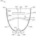
도 10은 법선 벡터(1011)를 갖는 스위칭가능 확산기(1010), 조명 컴포넌트(1020), 저-흡수 광학 컴포넌트(1030), 말단 에지(1063) 및 근위 에지(1066)를 갖는 반사성 또는 반투과성 외부 주 표면(1060), 광학적 체적(1070), 광 주입 영역(1073), 및 출력 주 표면(1075)을 포함하는 광학 시스템(1000)의 단면을 도시한다. 본 명세서에서 사용된 바와 같이, 말단 및 근위라는 용어는 광 주입 영역에 대한 위치를 지칭한다. 출력 주 표면(1075)은 반사성 또는 반투과성 외부 주 표면(1060)의 말단 에지(1063)에 인접한 말단 표면이다. 광 주입 영역(1073)은 반사성 또는 반투과성 외부 주 표면(1060)의 근위 에지(1066)에 인접한다. 도시된 실시예에서, 광 주입 영역(1073)은 광학적 체적(1070)의 입력 표면이다. 다른 실시예들에서, 광 주입 영역(1073)은 근위 에지(1066)에 인접하는 체적이며, 광원 또는 광원들 및/또는 렌즈 또는 렌즈들과 같은 광학 요소를 포함한다. 광원은 하나 이상의 발광 다이오드(LED)들을 포함할 수 있으며 광학적 체적(1026) 내로 연장될 수 있다. 도시된 실시예에서, 스위칭가능 확산기(1010)는 전체적으로 광학적 체적(1070) 내에 배치된다. 다른 실시예들에서, 스위칭가능 확산기는 광학적 체적 내에 단지 부분적으로 배치될 수 있다. 출력 주 표면(1075)은 말단 에지(1063)에 의해 정의되는 평면 표면일 수 있다. 예를 들어, 출력 주 표면(1075)은 말단 에지(1063)에 의해 경계를 이루는 평면 영역일 수 있다. 유사하게, 광 주입 영역(1073)은 근위 에지(1066)에 의해 정의되는 평면 표면일 수 있다. 예를 들어, 광 주입 영역(1073)은 근위 에지(1066)에 의해 경계를 이루는 평면 영역일 수 있다. 저-흡수 광학 컴포넌트(1030), 스위칭가능 확산기(1010) 및 조명 컴포넌트(1020)는 서로 광학적으로 연결된다.10 is a schematic diagram of a reflective or semi-transmissive outer circumference having a
도시된 실시예에서, 저-흡수 광학 컴포넌트(1030)는 다른 곳에서 기술된 범위들 중 임의의 범위 내에서 광학 시스템(1000)의 광출력의 FWHM을 증가시키도록 구성된 광 방향전환 구조체들을 포함하는 외부 표면들을 갖는다. 다른 실시예들에서, 저-흡수 광학 컴포넌트(1030) 및 스위칭가능 확산기(1010)의 외부 표면들 중 임의의 하나 이상은 광학 시스템(1000)의 광출력의 FWHM을 증가시키도록 구성된 광 방향전환 구조체들을 포함할 수 있다.In the illustrated embodiment, the low-absorption
조명 컴포넌트(1000)는 평균 광출력의 방향과 일치할(coincide) 수 있는 광축(1076)을 갖는다. 일부 실시예들에서, 평균 광출력의 방향은 조명 컴포넌트(1000)의 대칭축에 의해 결정된다. 일부 실시예들에서, 스위칭가능 확산기(1010), 저-흡수 광학 컴포넌트(1030), 및/또는 반사성 또는 반투과성 외부 주 표면(1060)은 비대칭이며, 평균 광출력의 방향은 스위칭가능 확산기(1010)의 상태에 의존할 수 있다. 일부 실시예들에서, 광학적 체적(1070)의 말단 표면인 출력 주 표면(1075)은 스위칭가능 확산기(1010)가 실질적으로 공간적으로 균일한 상태 - 실질적으로 투명 상태일 수 있거나 가장 낮은 탁도 상태일 수 있음 - 에 있을 때 광학적 체적(1070)의 평균 광출력 방향에 실질적으로 직교한다. 일부 실시예들에서, 출력 주 표면(1075)은 광축(1076)에 실질적으로 직교한다. 일부 실시예들에서, 스위칭가능 확산기(1010)는 스위칭가능 확산기(1010)의 적어도 일부분에서 광축(1076)에 평행하지 않은 법선 방향(1011)을 포함한다. 이는 스위칭가능 확산기가 도 10에 도시된 바와 같이 만곡된 형상을 갖는 경우에 발생할 수 있으며, 또는 편평한 스위칭가능 확산기가 광축(1076)에 대해 소정의 각도(°)에서 조명 컴포넌트(1000) 내에 배치되는 경우 발생할 수 있다. 다른 실시예들에서, 저-흡수 광학 컴포넌트(1030)는 저-흡수 광학 컴포넌트의 적어도 일부분에서, 광축(1076)에 평행하지 않은 법선 방향을 가질 수 있다. 법선 방향(1011)과 광축(1076) 사이의(또는 저-흡수 광학 컴포넌트의 법선 방향과 광축(1076) 사이의) 각도(°)는 10도 초과 또는 20도 초과 또는 30도 초과일 수 있고, 스위칭가능 확산기의 적어도 일부 섹션들에서(또는 저-흡수 광학 컴포넌트의 적어도 일부 섹션들에서) 90도 이하일 수 있다. 90도 초과의 각도는 90도 미만의 보각(complement angle)과 동등하므로, 단지 0도에서 90도까지의 각도만 고려하면 된다.The
일부 실시예들에서, 반사성 또는 반투과성 외부 주 표면(1060)은 균일하거나 실질적으로 균일한 반사율 및/또는 투과율을 가질 수 있지만, 다른 실시예들에서 반사성 또는 반투과성 외부 주 표면(1060)은 표면을 따라 변동하는 반사율 및/또는 투과율 특성을 가질 수 있다. 변동은 실질적으로 연속적일 수 있고, 또는 별개 영역들이 별개의 반사율 및/또는 투과율 특성을 가질 수 있다. 예를 들어, 영역(1060a) 및 영역(1060b)은 상이한 반사율 및/또는 투과율 특성을 가질 수 있다. 반사성 또는 반투과성 외부 주 표면(1060)은 공간적으로 변동되는 임의의 반사 특성을 가질 수 있다. 예를 들어, 반사율 대 투과율의 비율은 공간적으로 변동될 수 있다. 일부 실시예들에서, 공간적으로 변동되는 반사 특성들은 관심 파장 대역 내에서의 비편광 광의 반사율, 파장 대역 내에서의 제1 편광 상태를 갖는 편광 광의 반사율, 파장 대역 내에서의 비편광 광의 확산 반사율의 정도 및 파장 대역 내에서의 제1 편광 상태를 갖는 편광 광의 확산 반사율의 정도 중 하나 이상을 포함한다. 관심 파장 대역은 가시 파장 대역(예컨대, 380 nm 내지 780 nm 범위의 파장) 일 수 있으며, 또는 근 적외선(IR) 또는 자외선(UV) 대역일 수 있으며, 또는 가시광선, 적외선 및 자외선 범위 중 하나 이상과 중첩하는 대역들일 수 있다. 예를 들어, 근적외선은 780 nm 내지 2000 nm 범위의 파장을 지칭할 수 있다.In some embodiments, the reflective or semi-transmissive outer
반사성 또는 반투과성 외부 주 표면(1060)의 형상 및/또는 반사율 및/또는 투과율 특성은, 스위칭가능 확산기를 제1 상태로부터 제2 상태로 스위칭하면 조명 컴포넌트(1000)로부터의 광출력의 각도 분포 및/또는 스펙트럼 분포 및/또는 편광 분포가 변화되도록 선택될 수 있다. 예를 들어, 형상은 가변 표면 법선을 갖는 세그먼트화된(segmented) 또는 패싯형(faceted) 표면을 제공함으로써 조정될 수 있다. 반사성 또는 반투과성 외부 주 표면(1060)의 반사율 및/또는 투과율 특성은 또한 표면 텍스쳐(texture)를 변동시킴으로써 조정될 수 있다. 일부 실시예들에서, 반사성 또는 반투과성 외부 주 표면(1060)은 확산 반사율 또는 투과율의 공간적 변동 정도를 제공하는, 공간적으로 변동되는 텍스쳐를 가질 수 있다. 예를 들어, 일부 실시예들에서, 반사성 또는 반투과성 외부 주 표면(1060)은 공간적으로 변동되는, 확산 반사율 대 경면 반사율의 비율을 제공한다.The shape and / or reflectivity and / or transmittance characteristics of the reflective or semi-transmissive outer
광학적 체적의 반사성 또는 반투과성 외부 주 표면은 반사성 또는 반투과성 필름을 사용하여 형성될 수 있다. 적합한 반사성 또는 반투과성 필름은 미국 특허 제5,882,774호(존자(Jonza) 등), 제6,179,948호(메릴(Merrill) 등) 및 제6,783,349호(니빈(Neavin) 등)에 기술된 바와 같은 복수의 교번하는 복굴절 중합체(alternating birefringent polymer) 층들을 포함하는 다층 광학 필름(MOF)을 포함한다. 상이한 별개 반사율 및/또는 투과율 특성은 천공된 반사성 또는 반투과성 필름 - MOF일 수 있음 - 을 사용함으로써 달성될 수 있는데, 천공 밀도는 반사성 또는 반투과성 외부 주 표면을 따라 변동된다. 예를 들어, 반사성 또는 반투과성 외부 주 표면(1060)은 영역(1060a 및 1060b)에서 상이한 천공 밀도를 갖는 천공된 반사성 또는 반투과성 필름을 포함할 수 있다. 천공된 반사성 또는 반투과성 필름은 예를 들어 천공된 반사기 필름 또는 천공된 반사성 편광기일 수 있다. 천공된 반사기 필름은 강화된 경면 반사기(Enhanced Specular Reflector)(쓰리엠 컴퍼니(3M Company)에서 입수가능함)와 같은 광대역 반사기일 수 있고, 또는 반사 특성이 파장 의존적이도록 단지 일부 파장 대역에서만 반사성일 수도 있다. 적합한 반사성 편광기는 DBEF(쓰리엠 컴퍼니에서 입수가능함)를 포함한다. 다른 적합한 반사성 또는 반투과성 필름은 반투과성 디스플레이 필름(Transflective Display Film)(쓰리엠 컴퍼니에서 입수가능함)을 포함한다.The reflective or semi-transmissive outer major surface of the optical volume may be formed using a reflective or semipermeable film. Suitable reflective or semi-transmissive films include a plurality of alternating birefringence films as described in U.S. Patent No. 5,882,774 (Jonza et al.), 6,179,948 (Merrill et al), and 6,783,349 (Neavin et al. Layer optical film (MOF) comprising alternating birefringent polymer layers. Different distinct reflectance and / or transmissivity properties can be achieved by using a perforated reflective or semipermeable film - MOF, wherein the perforation density varies along a reflective or semi-permeable outer major surface. For example, the reflective or semi-permeable outer
일부 실시예들에서, 반사성 또는 반투과성 외부 주 표면(1060)은 기판에 부착된 하나 이상의 MOF 층들을 갖는 투명 기판을 사용하여 형성된다. 일부 실시예들에서, 하나 이상의 MOF 층들이 2개의 기판 사이에 배치될 수 있다. 이러한 실시예들에서, MOF 층들은 광학적 체적의 외부 경계를 정의하는 것으로 이해될 수 있고, 2개의 기판 층 중에 하나는 MOF 층들에 의해 설정되는 광학적 체적 외부에 있는 것으로 간주될 수 있다. 영역들(1060a 및 1060b)은 상이한 MOF 층들을 포함할 수 있다. MOF 층들은 광대역 반사기들, 파장 의존 반사기들, 반사성 편광기들, 비대칭 반사기들(제1 편광에 직교하는 제2 편광보다 제1 편광을 더 많이 반사하는 반사기), 또는 이들의 조합을 포함할 수 있다.In some embodiments, the reflective or semi-permeable outer
다른 반사기들 또는 반투과기들은 금속(예를 들어, 알루미늄) 반사기 또는 반투과기, 물리적 기상 증착에 의해 제조되는 반사기 또는 반투과기, 매트릭스 내의 입자들(예를 들어, 중합체 매트릭스 내의 반사성 입자들)을 갖는 반사기 또는 반투과기, 공극형(voided) 반사기 또는 반투과기(예를 들어, 확산 반사를 제공하기 위해 공극들을 포함하는 중합체 매트릭스 내의 반사성 입자들), 또는 내부 전반사(TIR)를 제공하는 반사기 또는 반투과기를 포함할 수 있지만, 이에 제한되지 않는다. 예를 들어, 폴리에스테르 매트릭스 내에 입자들을 포함하는 적합한 공극형 반사기들은 미국 특허 제7,273,640호(라니(Laney) 등)에 기술되어 있다.Other reflectors or transflectors may be selected from metal (e.g., aluminum) reflectors or transflectors, reflectors or transflectors fabricated by physical vapor deposition, particles in the matrix (e.g., reflective particles in a polymer matrix (E.g., reflective particles in polymeric matrices that include pores to provide diffuse reflection), or total internal reflection (TIR), having a reflective or semi-permeable, voided reflector or transflector But are not limited to, reflectors or transflectors. For example, suitable voided reflectors comprising particles in a polyester matrix are described in U.S. Patent No. 7,273,640 (Laney et al).
일부 실시예들에서, 광학적 체적은 예를 들어, 단일 방향으로 만곡되어 원뿔을 생성할 수 있거나, 또는 예를 들어, 두 방향으로 만곡되어 축을 중심으로 만곡된 회전면(surface of revolution)을 생성할 수 있는 단일의 반사성 또는 반투과성 외부 주 표면을 포함한다. 도 10에 도시된 실시예에서, 반사성 또는 반투과성 외부 주 표면(1060)은 광축(1076)을 중심으로 한 회전면으로서 설명될 수 있다. 일부 실시예들에서, 만곡된 회전면은 예를 들어, 축을 중심으로 하는 다수의 곡선들의 회전에 의해 생성될 수 있는 복합 곡선이다. 일부 실시예들에서, 광학적 체적은 2개 이상의 반사성 또는 반투과성 외부 주 표면을 포함할 수 있다. 적어도 하나의 반사성 또는 반투과성 외부 주 표면은 모두가 공통 평면에 있지는 않은 2개 이상의 평면 표면들을 포함할 수 있거나, 또는 한 방향으로 만곡되거나 두 방향으로 만곡된 하나 이상의 표면들을 포함할 수 있다.In some embodiments, the optical volume may, for example, be curved in a single direction to produce a cone, or it may be curved in two directions, for example, to create a curved surface of revolution about an axis And a single reflective or semi-permeable outer major surface. 10, the reflective or semi-transmissive outer
표면은, 광 주입 영역으로부터 광학적 체적 내로 주입되어 표면 상에 입사되는 관심 파장 대역의 광 에너지의 대부분을 반사하는 경우, 반사성인 것으로 기술될 수 있다. 예를 들어, 반사성 표면은, 표면 상에 입사되고 광 주입 영역으로부터 광학적 체적 내로 주입되는 광 에너지의 적어도 약 70 퍼센트, 또는 적어도 약 80 퍼센트, 또는 적어도 약 90 퍼센트를 반사할 수 있다. 다른 곳에서 기술한 바와 같이, 관심 파장 대역은 가시광선, IR 및/또는 UV 범위의 광을 포함할 수 있다. 표면은, 광 주입 영역으로부터 광학적 체적 내로 주입되어 표면 상에 입사되는 관심 파장 대역의 광 에너지의 일부를 반사하고 일부를 투과하는 경우, 반투과성인 것으로 기술될 수 있다. 예를 들어, 반투과성 표면은, 표면 상에 입사되고 광 주입 영역으로부터 광학적 체적 내로 주입되는 광 에너지의 10 퍼센트 내지 90 퍼센트 범위 내에서 반사할 수 있으며, 표면 상에 입사되고 광 주입 영역으로부터 광학적 체적 내로 주입되는 광 에너지의 10 퍼센트 내지 90 퍼센트 범위 내에서 투과할 수 있다. 반투과성 표면은, 표면 상에 입사되고 내부 전반사(TIR) 메커니즘을 통해 광 주입 영역으로부터 광학적 체적 내로 주입되는 광 에너지의 상당한 부분을 반사할 수 있다.The surface can be described as being reflective if it reflects most of the light energy of the wavelength band of interest injected into the optical volume from the light-injecting region and incident on the surface. For example, the reflective surface may reflect at least about 70 percent, or at least about 80 percent, or at least about 90 percent of the light energy incident on the surface and injected into the optical volume from the light-injecting region. As described elsewhere, the wavelength band of interest may include visible light, IR and / or UV range light. The surface can be described as being semi-transmissive if it reflects and transmits a portion of the light energy of the wavelength band of interest injected into the optical volume from the light injection region and incident on the surface. For example, a semipermeable surface can be reflected within a range of 10 percent to 90 percent of the light energy incident on the surface and injected into the optical volume from the light injection region, and incident on the surface and into the optical volume And can transmit within a range of 10 percent to 90 percent of the light energy injected. The semipermeable surface can reflect a significant portion of the light energy incident on the surface and injected into the optical volume from the light injection region through an internal total reflection (TIR) mechanism.
본 명세서의 광학 시스템들과 함께 사용하기에 적합한 다른 광학적 체적들은 미국 가특허 출원 제62/076946호(듀(Du) 등)에 기술되어 있다.Other optical volumes suitable for use with the optical systems herein are described in U. S. Patent Application No. 62/076946 (Du et al.).
일부 실시예들에서, 본 명세서의 광학 시스템은 조명 컴포넌트, 스위칭가능 확산기 및 저-흡수 광학 컴포넌트와 광학적으로 연결되는 렌즈를 포함한다. 도 14는 스위칭가능 확산기(1410), 조명 컴포넌트(1420), 광 방향전환 구조체들(1435)을 포함하는 외부 표면(1434)을 갖는 저-흡수 광학 컴포넌트(1430), 및 렌즈(1483)를 포함하는 광학 시스템(1400)의 개략적인 단면도이다. 스위칭가능 확산기(1410)는 조명 컴포넌트(1420)와 저-흡수 광학 컴포넌트(1430) 사이에 배치되고 렌즈(1483)는 스위칭가능 확산기(1410)와 저-흡수 광학 컴포넌트(1430) 사이에 배치된다. 임의의 적합한 렌즈가 사용될 수 있다. 일부 실시예들에서, 렌즈는 내부 전반사 렌즈(TIR 렌즈)이며, 여기서 스위칭가능 확산기(1410)를 통해 렌즈(1483)에 입사하는 조명 컴포넌트(1420)로부터의 광은 TIR을 통해 렌즈(1483)의 외부 표면으로부터 반사된다. 렌즈는, 제1 표면적을 갖는 스위칭가능 확산기로부터 제1 표면적보다 큰 제2 표면적을 갖는 저-흡수 광학 컴포넌트 상으로 광을 지향시키기 위해, 스위칭가능 확산기(1410)와 저-흡수 광학 컴포넌트(1430) 사이에 배치될 수 있다.In some embodiments, the optical system herein includes a lens optically coupled to an illumination component, a switchable diffuser, and a low-absorption optical component. 14 includes a low-absorption
본 명세서의 스위칭가능 확산기들 중 임의의 것은 복수의 독립적으로 어드레스가능한 영역을 포함할 수 있다. 일부 실시예들에서, 복수의 독립적으로 어드레스가능한 영역은 수동 매트릭스 어드레스가능하다. 각각의 영역은 제1 상태 및 제1 상태와는 상이한 제2 상태에 있을 수 있다. 예를 들어, 제1 상태는 투명하거나 가장 낮은 탁도 상태일 수 있고 제2 상태는 높은 탁도 상태일 수 있다. 일부 실시예들에서, 각각의 영역은 제1 상태, 제1 상태와는 상이한 제2 상태, 및 제1 및 제2 상태와는 상이한 제3 상태에 있을 수 있다. 예를 들어, 제1 상태는 낮은 탁도를 가질 수 있고, 제2 상태는 제1 상태의 탁도보다 더 높은 탁도를 가질 수 있고, 제3 상태는 제2 상태의 탁도보다 더 높은 탁도를 가질 수 있다. 일부 실시예들에서, 각각의 영역은 스위칭가능 확산기에 의해 달성될 수 있는 가장 높은 탁도를 갖는 최대 탁도 상태에 있을 수 있고, 각각의 영역은 스위칭가능 확산기에 의해 달성될 수 있는 가장 낮은 탁도를 갖는 최소 탁도에 있을 수 있다. 일부 실시예들에서, 각각의 영역은 최소 탁도 상태, 및 최소 탁도 상태로부터 최대 탁도 상태까지 실질적으로 연속적으로 달라질 수 있는 복수의 혼탁 상태 중 임의의 상태에 있을 수 있다.Any of the switchable diffusers herein may include a plurality of independently addressable areas. In some embodiments, the plurality of independently addressable regions are passive matrix addressable. Each region may be in a first state and a second state different from the first state. For example, the first state may be transparent or the lowest turbidity state, and the second state may be a high turbidity state. In some embodiments, each region may be in a first state, a second state different from the first state, and a third state different from the first and second states. For example, the first state may have a lower turbidity, the second state may have a turbidity higher than the turbidity of the first state, and the third state may have a turbidity higher than the turbidity of the second state . In some embodiments, each region may be in a maximum turbidity state having the highest turbidity that can be achieved by the switchable diffuser, and each region may have the lowest turbidity that can be achieved by the switchable diffuser It may be at a minimum turbidity. In some embodiments, each region may be in any of a plurality of turbidity states that may vary substantially in continuous from a minimum turbidity condition, and a minimum turbidity condition to a maximum turbidity condition.
확산기의 상태를 변화시키기 위해 전압 파형이 스위칭가능 확산기에 인가될 수 있다. 일부 실시예들에서, 파형은 스위칭 장치를 사용하여 인가된다. 일부 실시예들에서, 스위칭 장치가 스위칭가능 확산기의 컴포넌트로서 제공된다. 일부 실시예들에서, 스위칭 장치가 스위칭가능 확산기를 포함하는 하우징 내에 배치될 수 있다. 일부 실시예들에서, 스위칭 장치가 스위칭가능 확산기를 수용하는 하우징에 대해 외부에 위치되는 물리적으로 별개의 컴포넌트로서 제공될 수 있다. 일부 실시예들에서, 스위칭가능 확산기는 스멕틱 A 재료의 층을 포함한다. 일부 실시예들에서, 스멕틱 A 재료의 두께는 5 마이크로미터 내지 20 마이크로미터의 범위이다.A voltage waveform may be applied to the switchable diffuser to change the state of the diffuser. In some embodiments, the waveform is applied using a switching device. In some embodiments, a switching device is provided as a component of a switchable diffuser. In some embodiments, the switching device may be disposed in a housing that includes a switchable diffuser. In some embodiments, the switching device may be provided as a physically separate component located externally to the housing housing the switchable diffuser. In some embodiments, the switchable diffuser comprises a layer of Smectic A material. In some embodiments, the thickness of the Smectic A material ranges from 5 micrometers to 20 micrometers.
스멕틱 A 재료, 또는 다른 스위칭가능 확산기 재료가 상태를 변화시키게 하는 데 필요한 전압 파형은 당업계에 알려져 있다. 적합한 파형들은, 예를 들어, 미국 특허 제4,893,117호(블롬니(Blomley) 등)에 기술되어 있다. 일부 실시예들에서, 저-주파수 파형이 영역을 투명 상태로부터 혼탁 상태로 스위칭하기 위해 인가되고, 고-주파수 파형이 영역을 혼탁 상태로부터 투명 상태로 스위칭하기 위해 사용된다. 일부 실시예들에서, 저-주파수 파형은 약 10 ㎐ 내지 약 100 ㎐의 범위(예를 들어, 약 50 ㎐)의 주파수를 갖는다. 일부 실시예들에서, 고-주파수 파형은 약 0.5 ㎑ 내지 약 4 ㎑의 범위(예를 들어, 약 1 ㎑)의 주파수를 갖는다.The voltage waveforms required to cause the Smectic A material, or other switchable diffuser material, to change state are known in the art. Suitable waveforms are described, for example, in U.S. Patent No. 4,893,117 (Blomley et al.). In some embodiments, a low-frequency waveform is applied to switch the region from the transparent state to the turbid state, and the high-frequency waveform is used to switch the region from the turbid state to the transparent state. In some embodiments, the low-frequency waveform has a frequency in the range of about 10 Hz to about 100 Hz (e.g., about 50 Hz). In some embodiments, the high-frequency waveform has a frequency in the range of about 0.5 kHz to about 4 kHz (e.g., about 1 kHz).
혼탁 상태는 투명 상태에 있는 스위칭가능 확산기에 전압 파형이 인가되는 시간에 의해 조정될 수 있다. 예를 들어, 제1 기간 동안 실질적 투명 상태에 있는 스위칭가능 확산기에 인가되는 저-주파수 파형이 제1 탁도를 갖는 제1 혼탁 상태를 생성할 수 있고, 제2 기간 동안 실질적 투명 상태에 있는 스위칭가능 확산기에 인가되는 저-주파수 파형이 제1 탁도와는 상이한 제2 탁도를 갖는 제2 혼탁 상태를 생성할 수 있다. 예를 들어, 제1 기간은 800 ms일 수 있고 제2 기간은 400 ms일 수 있어서, 제2 탁도보다 높은 제1 탁도를 생성할 수 있다.The turbidity state can be adjusted by the time the voltage waveform is applied to the switchable diffuser in a transparent state. For example, a low-frequency waveform applied to a switchable diffuser in a substantially transparent state during a first period of time may produce a first turbidity with a first turbidity, The low-frequency waveform applied to the diffuser can produce a second turbidity state having a second turbidity different from the first turbidity. For example, the first period may be 800 ms and the second period may be 400 ms, thereby producing a first turbidity higher than the second turbidity.
일부 실시예들에서, 스위칭가능 확산기가 일부 영역이 투명 상태에 있고 일부 영역이 혼탁 상태에 있으며 투명 상태로부터 혼탁 상태로의 상태 변화 및 혼탁 상태로부터 투명 상태로의 상태 변화 둘 모두가 필요한 상태에 있을 때, 확산기 제어기는 우선 투명 상태로부터 혼탁 상태로 변화되어야 하는 그 영역에 저-주파수 파형을 인가한 다음에 혼탁 상태로부터 투명 상태로 변화되어야 하는 그 영역에 고-주파수 파형을 인가하도록 구성될 수 있다. 일부 실시예들에서, 스위칭가능 확산기가 일부 영역이 투명 상태에 있고 일부 영역이 혼탁 상태에 있으며 투명 상태로부터 혼탁 상태로의 상태 변화 및 혼탁 상태로부터 투명 상태로의 상태 변화 둘 모두가 필요한 상태에 있을 때, 확산기 제어기는 우선 혼탁 상태로부터 투명 상태로 변화되어야 하는 그 영역에 고-주파수 파형을 인가한 다음에 투명 상태로부터 혼탁 상태로 변화되어야 하는 그 영역에 저-주파수 파형을 인가하도록 구성된다. 일부 실시예들에서, 스위칭가능 확산기가 일부 영역이 투명 상태에 있고 일부 영역이 혼탁 상태에 있으며 투명 상태로부터 혼탁 상태로의 상태 변화 및 혼탁 상태로부터 투명 상태로의 상태 변화 둘 모두가 필요한 상태에 있을 때, 확산기 제어기는 제1 기간에 투명 상태로부터 혼탁 상태로 변화되어야 하는 그 영역에 저-주파수 파형을 인가하고 제2 기간에 혼탁 상태로부터 투명 상태로 변화되어야 하는 그 영역에 고-주파수 파형을 인가하도록 구성되며, 여기서 제1 기간과 제2 기간은 중첩한다.In some embodiments, when the switchable diffuser is in a state in which some of the regions are in a transparent state, some of the regions are in a turbidity state, and a state change from a transparent state to a cloudy state and a state change from a cloudy state to a transparent state are both in a necessary state , The diffuser controller can be configured to first apply a low-frequency waveform to the region, which must first change from a transparent state to a turbid state, and then a high-frequency waveform, to that region, which must change from a turbid state to a transparent state . In some embodiments, when the switchable diffuser is in a state in which some of the regions are in a transparent state, some of the regions are in a turbidity state, and a state change from a transparent state to a cloudy state and a state change from a cloudy state to a transparent state are both in a necessary state The diffuser controller is configured to first apply a high-frequency waveform to the region that must first change from the turbid state to the transparent state, and then apply the low-frequency waveform to the region that must change from the transparent state to the turbid state. In some embodiments, when the switchable diffuser is in a state in which some of the regions are in a transparent state, some of the regions are in a turbidity state, and a state change from a transparent state to a cloudy state and a state change from a cloudy state to a transparent state are both in a necessary state , The diffuser controller applies a low-frequency waveform to the region that must change from the transparent state to the turbid state in the first period and a high-frequency waveform to that region that must change from the turbid state to the transparent state in the second period Wherein the first period overlaps with the second period.
도 11a는 제1 내지 제9 독립적으로 어드레스가능한 영역들(1110A-1 내지 1110A-9)을 갖는 스위칭가능 확산기(1110A)의 평면도이다. 도 11b는 제1 내지 제3 독립적으로 어드레스가능한 영역들(1110B-1 내지 1110B-3)을 갖는 스위칭가능 확산기(1110B)의 평면도이다. 도 7c는 제1 내지 제4 독립적으로 어드레스가능한 영역들(1110C-1 내지 1110C-4)을 갖는 스위칭가능 확산기(1110C)의 평면도이다. 스위칭가능 확산기(1110C)는 영역들(1174)에서 스위칭가능 확산기(1110C) 상에 광을 생성하는 4개의 LED를 갖는 광원 위에 배치된다. 각각의 독립적으로 어드레스가능한 영역은 LED에 대응한다. 이러한 배열은 조명 컴포넌트의 광출력의 유용한 정도의 조정가능성을 허용한다. LED들은 상이한 스펙트럼 파워 분포 기능들을 가질 수 있거나(예컨대, LED들은 상이한 컬러의 LED들일 수 있음), 또는 그들은 모두 실질적으로 동일한 스펙트럼 파워 분포 기능을 가질 수 있다(예컨대, 모든 LED들이 백색일 수 있는 동일한 컬러를 가질 수 있음). LED들이 상이한 컬러의 LED들인 경우, 상이한 방향으로 상이한 색조의 광출력을 생성할 수 있는 다양한 컬러의 출력 분포를 제어하기 위해 스위칭가능 확산기(1110C)가 사용될 수 있다. 이것은, 예를 들어, 무대 조명과 같은 다양한 조명 응용에 유용할 수 있다. 4개의 LED 및 4개의 어드레스가능한 영역이 도 11c에 도시되었지만, 임의의 수의 LED 및 임의의 수의 독립적으로 어드레스가능한 영역이 사용될 수 있다. 일부 실시예들에서, 스위칭가능 확산기는 복수의 LED들과 정합될 수 있으나, LED들의 개수와 스위칭가능 확산기의 어드레스가능한 영역들의 개수와 일대일 대응이 있을 수도 있고 없을 수도 있다. 예를 들어, 스위칭가능 확산기의 단일 영역에 대응하는 2개 이상의 LED들이 있을 수 있다.11A is a plan view of a
세그먼트화된 층과 같은 추가적인 광학 층들이 스위칭가능 확산기에 인접하게 배치될 수 있다. 일부 실시예들에서, 세그먼트화된 층은 스위칭가능 확산기에 인접하게 배치되고, 스위칭가능 확산기의 독립적으로 어드레스가능한 영역들과 정렬된다. 세그먼트화된 층은 각각 광학 효과를 생성하는 다수의 세그먼트들을 가질 수 있다. 일부 실시예들에서, 스위칭가능 확산기 및 세그먼트화된 층은 LED들과 정합될 수 있으며(예를 들어, 도 11c와 같이), 각각의 세그먼트는 그의 대응하는 LED로부터의 광출력을 조정한다. 예를 들어, 스위칭가능 확산기의 대응하는 영역이 실질적으로 투명 상태에 있는 경우에, 세그먼트화된 층을 통과한 후의 제1 LED의 출력 분포는 (스위칭가능 확산기에 평행한 평면에서) 실질적으로 원형 분포를 가질 수 있는 한편, 스위칭가능 확산기의 대응하는 영역이 실질적으로 투명 상태에 있는 경우에, 세그먼트화된 층을 통과한 후의 제2 LED의 출력 분포는 (스위칭가능 확산기에 평행한 평면에서) 타원 분포를 가질 수 있다. 세그먼트화된 층은 층의 상이한 세그먼트들에서 변동되는 복제된 패턴(예컨대, 미세복제됨)을 가질 수 있다. 세그먼트화된 층에 사용될 수 있는 적합한 물질은 예를 들어, 표면 릴리프 홀로그램(surface relief hologram)을 이용할 수 있는 루미니트, 엘엘씨(Luminit, LLC)(미국 캘리포니아주 토랜스 소재)로부터 입수가능한 확산기를 포함한다. 스위칭가능 확산기와 세그먼트화된 층의 조합 - 스위칭가능 확산기의 독립적으로 어드레스가능한 영역들이 세그먼트화된 층과 정합되고 복수의 LED들과 정합됨 - 은 조명 컴포넌트의 광출력에 대한 고도의 조정가능성을 허용한다.Additional optical layers, such as segmented layers, may be disposed adjacent the switchable diffuser. In some embodiments, the segmented layer is disposed adjacent to the switchable diffuser and is aligned with the independently addressable regions of the switchable diffuser. The segmented layer may each have a plurality of segments that produce optical effects. In some embodiments, the switchable diffuser and the segmented layer may be matched to the LEDs (e.g., as in Figure 11C) and each segment adjusts its light output from its corresponding LED. For example, if the corresponding region of the switchable diffuser is in a substantially transparent state, the output distribution of the first LED after passing through the segmented layer is substantially circular (in a plane parallel to the switchable diffuser) While the output distribution of the second LED after passing through the segmented layer (in a plane parallel to the switchable diffuser) may have an elliptical distribution (in a plane parallel to the switchable diffuser), whereas if the corresponding region of the switchable diffuser is substantially transparent, Lt; / RTI > The segmented layer may have a replicated pattern (e. G., Micro-replicated) that varies in different segments of the layer. Suitable materials that may be used in the segmented layer include, for example, diffusers available from Luminit, LLC (Torrance, CA), which may utilize surface relief holograms do. The combination of the switchable diffuser and the segmented layer-the independently addressable regions of the switchable diffuser match the segmented layer and are matched with the plurality of LEDs-allow for a high degree of coordination of the light output of the illumination component do.
9개, 3개 및 4개의 독립적으로 어드레스가능한 영역들이 도 11a 내지 도 11c에 각각 도시되었으나, 임의의 수의 독립적인 어드레스가능한 영역들이 사용될 수 있다. 예를 들어, 스위칭가능 확산기는 적어도 10개 또는 적어도 100개의 독립적으로 어드레스가능한 영역들을 포함하는 독립적으로 어드레스가능한 영역들의 x-y 그리드(grid)를 가질 수 있다. 이것은, 적어도 하나의 반사성 또는 반투과성 표면이 x-y 그리드 내의 위치를 통과하는 광 주입 영역으로부터의 광이 특정 방향으로 반사되게 하는 형상일 수 있는 실시예들에 대해 유용할 수 있다. 독립적으로 어드레스가능한 영역들의 x-y 그리드를 가짐으로써 조명 컴포넌트로부터의 각도, 스펙트럼 및/또는 편광 출력 분포에 고도의 조정가능성을 허용할 수 있다. 본 명세서의 광학 시스템들과 함께 사용하기에 적합한 다른 적합한 스위칭가능 확산기들은 미국 가특허 출원 제62/076946호(듀(Du) 등)에 기술되어 있다.Although nine, three, and four independently addressable areas are shown in Figures 11A-11C, respectively, any number of independent addressable areas may be used. For example, the switchable diffuser may have an x-y grid of independently addressable areas comprising at least ten or at least 100 independently addressable areas. This may be useful for embodiments in which at least one reflective or semi-transmissive surface may be a shape that causes light from the light-injecting region to pass through the location in the x-y grid to be reflected in a particular direction. By having an x-y grid of independently addressable areas, a high degree of coordination of the angle, spectrum and / or polarization power distribution from the illumination component is allowed. Other suitable switchable diffusers suitable for use with the optical systems herein are described in U. S. Patent Application No. 62/076946 (Du et al.).
도 12는 전기적 스위칭가능 확산기일 수 있거나 저-흡수 광학 컴포넌트일 수 있는 광학 컴포넌트(1290)의 단면도이다. 광학 컴포넌트(1290)는 본 명세서의 광학 시스템들 중 임의의 것에서 사용되는 스위칭가능 확산기 또는 저-흡수 광학 컴포넌트들 중 임의의 것에 대응할 수 있다. 광학 컴포넌트(1290)는 제1 영역(1294) 내의 광 방향전환 구조체들의 제1 세트(1292), 및 제2 영역(1298) 내의 광 방향전환 구조체들의 제2 세트(1296)를 포함한다. 광 방향전환 구조체들의 제1 세트(1292)는 광 방향전환 구조체들의 제2 세트(1296)와 상이하다. 예시된 실시예에서, 광 방향전환 구조체들의 제1 세트(1292)는 광 방향전환 구조체들의 제2 세트(1296)보다 큰 크기를 갖는다. 일부 실시예들에서, 광 방향전환 구조체들의 제1 및 제2 세트는 크기, 형상, 간격 또는 경사의 상이한 분포들을 갖는다. 예시된 실시예에서, 광학 컴포넌트의 동일한 면 상에 광 방향전환 구조체들의 2개의 영역이 있다. 다른 실시예들에서, 2개 초과의 영역이 있고, 그 영역들은 광학 컴포넌트(1290)의 외부 표면들 중 하나 또는 둘 모두 상에 배치될 수 있다.12 is a cross-sectional view of an
일부 실시예들에서, 광 방향전환 구조체들은 크기, 형상 및 간격의 공간적으로 규칙적인 분포들을 갖는다. 일부 실시예들에서, 광 방향전환 구조체들은 크기, 형상 및 간격 중 적어도 하나의 공간적으로 불규칙적인(랜덤 또는 의사-랜덤) 분포를 갖는다. 일부 실시예들에서, 광 방향전환 구조체들은 굴절 구조체, 회절 구조체, 또는 이들의 조합을 포함한다.In some embodiments, the light direction switching structures have spatially regular distributions of size, shape, and spacing. In some embodiments, the light direction switching structures have a spatially irregular (random or pseudo-random) distribution of at least one of size, shape, and spacing. In some embodiments, the light direction change structures include a refractive structure, a diffractive structure, or a combination thereof.
광 방향전환 구조체들은 임의의 다양한 적합한 수단을 사용하여 광학 컴포넌트(예를 들어, 스위칭가능 확산기 또는 저-흡수 광학 컴포넌트)의 외부 표면 상에 형성될 수 있다. 예를 들어, 광 방향전환 구조체들은, 바람직한 패턴 또는 구조체를 포함하는 미세복제된 공구를 사용하여, 그것이 공구 표면과 접촉해 있을 때 중합성 수지 조성물을 외부 표면 상에 캐스팅하고 수지 조성물을 경화시킴으로써 형성될 수 있다. 이러한 캐스팅 및 경화 공정들은 예를 들어, 미국 특허 제5,175,030호(루(Lu) 등) 및 미국 특허 제5,183,597호(루(Lu))에 기술되어 있다. 엠보싱 또는 다른 표면 구조화 방법들도 사용될 수 있다.The light redirecting structures may be formed on the outer surface of an optical component (e.g., a switchable diffuser or a low-absorption optical component) using any of a variety of suitable means. For example, the light redirecting structures may be formed by casting a polymeric resin composition onto an exterior surface and curing the resin composition using a microreplicated tool comprising the desired pattern or structure, when it is in contact with the tool surface . Such casting and curing processes are described, for example, in U.S. Patent No. 5,175,030 (Lu et al.) And U.S. Patent No. 5,183,597 (Lu). Embossing or other surface structuring methods may also be used.
광 방향전환 구조체들은 임의의 적합한 형상 또는 형상들의 분포를 가질 수 있다. 적합한 형상들은 예를 들어, 렌즈릿, 선형 프리즘, 피라미드, 원뿔, 및 이들의 조합을 포함한다. 포함될 때, 렌즈릿들은 임의의 적합한 형상을 가질 수 있고 아치형 단면을 가질 수 있다. 렌즈릿들은 예를 들어, 구형 또는 타원형 캡들일 수 있다. 형상들은 랜덤으로 또는 의사-랜덤으로 배열될 수 있거나, 또는 정사각형 격자 또는 또는 육각형 격자 - 이는 정삼각형 격자로도 지칭될 수 있음 - 와 같은 반복 패턴으로 배열될 수 있다. 일부 실시예들에서, 광 방향전환 구조체들은 표면을 실질적으로 덮으며, 이때 이웃하는 광 방향전환 구조체들은 서로 바로 인접해 있다. 일부 실시예들에서, 광 방향전환 구조체들은 이웃하는 구조체들 사이에 공간을 가지면서 배열될 수 있다. 일부 실시예들에서, 광 방향전환 구조체들은 주기적 분포와 같은 공간적으로 불변인 분포로 배열된다. 일부 실시예들에서, 광 방향전환 구조체들은 랜덤 또는 다른 식으로 비주기적인 분포와 같은 공간적으로 변형된 분포로 배열된다. 일부 실시예들에서, 광 방향전환 구조체들은 원, 타원 등 상에 배열될 수 있는, 렌즈형 구조체들과 같은 동심 링들의 구조체들로 배열된다. 일부 실시예들에서, 광 방향전환 구조체들은 사행 프리즘(serpentine prism)들과 같은 사행 렌즈형 구조체들일 수 있다.The light redirecting structures may have any suitable shape or distribution of shapes. Suitable shapes include, for example, lenslets, linear prisms, pyramids, cones, and combinations thereof. When included, the lenslets may have any suitable shape and may have an arcuate cross-section. The lenslets may, for example, be spherical or elliptical caps. The shapes may be randomly or pseudo-randomly arranged, or arranged in a repeating pattern such as a square lattice or a hexagonal lattice, which may also be referred to as a regular triangular lattice. In some embodiments, the light direction switching structures substantially cover the surface, wherein neighboring light direction switching structures are immediately adjacent to each other. In some embodiments, the light direction switching structures may be arranged with a space between neighboring structures. In some embodiments, the light direction conversion structures are arranged in a spatially invariant distribution, such as a periodic distribution. In some embodiments, the light direction switching structures are arranged in a spatially deformed distribution, such as an aperiodic distribution, at random or otherwise. In some embodiments, the light direction switching structures are arranged into structures of concentric rings, such as lenticular structures, which may be arranged on a circle, an ellipse, or the like. In some embodiments, the light direction switching structures may be meandering lenticular structures, such as serpentine prisms.
일부 실시예들에서, 광 방향전환 구조체들의 표면적의 적어도 약 50 퍼센트, 또는 적어도 약 60 퍼센트, 또는 적어도 약 80 퍼센트, 또는 적어도 약 90 퍼센트는 약 10도, 또는 약 15도 내지 약 40도, 또는 약 45도의 범위 내의 기판의 평면의 법선에 대한 각도를 갖는 표면 법선을 갖는다.In some embodiments, at least about 50 percent, or at least about 60 percent, or at least about 80 percent, or at least about 90 percent, of the surface area of the light redirecting structures is about 10 degrees, or about 15 degrees to about 40 degrees, And has a surface normal with an angle to the normal of the plane of the substrate within a range of about 45 degrees.
구형 캡들이, 저-흡수 광학 컴포넌트일 수 있거나 스위칭가능 확산기일 수 있는 광학 컴포넌트(1530)의 일부분의 개략적인 단면도인 도 15에 도시되어 있다. 광학 컴포넌트(1530)는 기판(1531), 및 도시된 실시예들에서 반 원호 각(1588)을 갖는 구형 캡들인 광 방향전환 구조체들(1535)을 포함하는 구조화된 표면(1534)을 포함한다. 광 방향전환 구조체들(1535)은, 기판의 평면에 대해 각도(θ)(0도 내지 90도의 범위로 취해짐)를 이루고 기판의 평면에 대한 법선에 대해 각도(α)(이는 90도 마이너스 θ와 동일함)를 이루는 표면 법선(1586)을 갖는다. 광 방향전환 구조체들(1535)은 조명 컴포넌트 쪽으로 또는 그로부터 멀어지는 방향으로 향할 수 있다. 일부 실시예들에서, 구형 캡들은 광원으로부터 멀어지는 방향으로 향하고, 약 25도, 또는 약 30도 내지 약 40도 또는 약 45도의 범위 내의 반 원호 각(1588)을 갖는다. 일부 실시예들에서, 표면 법선과 기판의 평면에 대한 법선 사이의 각도(α)의 구조화된 표면(1534)에 대한 평균은 10도, 또는 15도, 또는 20도 내지 30도, 35도 또는 40도의 범위 내에 있다. 일부 실시예들에서, 표면 법선과 기판의 평면 사이의 각도(θ)의 구조화된 표면(1534)에 대한 평균은 50도, 또는 55도, 또는 60도, 내지 70도, 또는 75도, 또는 80도의 범위 내에 있다. 일부 실시예들에서, 구형 캡들은 광원 쪽으로 향하고, 약 30도 또는 약 35도 내지 약 80도 또는 약 90도의 범위 내의 반 원호 각(1588)을 갖는다. 일부 실시예들에서, 표면 법선과 기판의 평면에 대한 법선 사이의 각도(α)의 구조화된 표면(1534)에 대한 평균은 15도 또는 20도 내지 60도, 또는 65도의 범위 내에 있다. 일부 실시예들에서, 표면 법선과 기판의 평면 사이의 각도(θ)의 구조화된 표면(1534)에 대한 평균은 30도 또는 35도 내지 70도 또는 75도의 범위 내에 있다. 예들에 도시된 바와 같이, 이러한 기하학적 구조들은 광학 컴포넌트를 통한 높은 투과율을 유지하면서 원하는 레벨들의 광 확산을 제공하는 것으로 밝혀졌다.The spherical caps are shown in Figure 15, which is a schematic cross-sectional view of a portion of an
선형 프리즘들이, 저-흡수 광학 컴포넌트일 수 있거나 스위칭가능 확산기일 수 있는 광학 컴포넌트(1630)의 일부분의 개략적인 단면도인 도 16에 도시되어 있다. 광학 컴포넌트(1630)는 기판(1631), 및 도시된 실시예들에서 꼭지각(1687)을 갖고 경사각(slope angle)(1689)을 갖는 선형 프리즘들인 광 방향전환 구조체들(1635)을 포함하는 구조화된 표면(1634)을 포함한다. 편평한 면들을 갖는 프리즘들의 경우, 경사각(1689)은 표면(1634)에 대한 법선과 기판의 평면 사이의 각도와 동일하다. 광 방향전환 구조체들(1635)은 조명 컴포넌트 쪽으로 또는 그로부터 멀어지는 방향으로 향할 수 있다. 일부 실시예들에서, 프리즘들은 광원으로부터 멀어지는 방향으로 향하고, 약 10도(약 160도의 꼭지각(1687)에 대응함), 또는 약 15도(약 150도의 꼭지각(1687)에 대응함) 내지 약 30도(약 120도의 꼭지각(1687)에 대응함), 또는 약 35도(약 110도의 꼭지각(1687)에 대응함)의 범위 내의 경사각(1689)을 갖는다. 일부 실시예들에서, 프리즘들은 광원 쪽으로 향하고, 약 10도(약 160도의 꼭지각(1687)에 대응함), 또는 약 15도(약 150도의 꼭지각(1687)에 대응함) 내지 약 40도(약 100도의 꼭지각(1687)에 대응함), 또는 약 45도(약 90도의 꼭지각(1687)에 대응함)의 범위 내의 경사각(1689)을 갖는다. 예들에 도시된 바와 같이, 이러한 기하학적 구조들은 광학 컴포넌트를 통한 높은 투과율을 유지하면서 원하는 레벨들의 광 확산을 제공하는 것으로 밝혀졌다.Linear prisms are shown in Fig. 16, which is a schematic cross-sectional view of a portion of an
상대적으로 큰 경사를 갖는 원뿔들은, 일부 응용들에서 바람직할 수 있는 높은 강도의 링 형상 영역을 갖는 출력 분포를 제공할 수 있다. 상대적으로 큰 경사각들을 갖는 선형 프리즘들은, 일부 응용들에서 바람직할 수 있는 높은 강도의 2개-로브(lobed) 형상의 영역을 갖는 출력 분포를 제공할 수 있다. 베이스 및 n개-면들을 갖는 피라미드들(n은 임의의 적합한 수일 수 있고, 예를 들어 3, 4, 5 또는 6일 수 있음)은, 일부 응용들에서 바람직할 수 있는 높은 강도의 n개-로브 형상의 영역을 갖는 출력 분포를 제공하는 데 사용될 수 있다. 상대적으로 가파른 경사들 및 상대적으로 날카로운 피크들을 갖는 벽들을 가진 날카로운 팁의 피라미드들은 n개-로브 출력 분포들을 생성하는 경향이 있다. 상대적으로 얕은 경사들을 갖는 벽들을 갖는 피라미드들 및 둥근 팁 피크들을 갖는 피라미드들은, 로브들이 함께 병합되는 출력 분포를 생성하는 경향이 있다. 이러한 배포들은 일부 응용들에서 바람직할 수 있다. 원뿔들의 경우의 링 형상의 분포 또는 프리즘들 또는 피라미드들의 경우의 로브들을 생성하는 데 필요한 경사는, 날카로운 피크의 입력광에 대해 링 형상의 영역을 생성하는 데 필요한 상대적으로 얕은 경사를 갖고 더 넓은 분포들을 갖는 광입력들에 필요한 더 높은 경사를 갖는 입력광 분포에 의존할 수 있다.Cones with a relatively large slope can provide an output distribution with a high intensity ring shaped area that may be desirable in some applications. Linear prisms with relatively large tilt angles can provide an output distribution with a high intensity, two-lobed shaped area that may be desirable in some applications. Base, and pyramids with n-planes, where n can be any suitable number and can be, for example, 3, 4, 5, or 6, Can be used to provide an output distribution having a lobed region. The pyramids of sharp tips with relatively steep slopes and walls with relatively sharp peaks tend to produce n-lobe power distributions. Pyramids with walls with relatively shallow slopes and pyramids with rounded tip peaks tend to produce an output distribution in which the lobes are merged together. Such distributions may be desirable in some applications. The distribution of the ring shape in the case of cones or the inclination required to create the lobes in the case of prisms or pyramids has a relatively shallow inclination necessary to create a ring shaped area for a sharp peak of input light, Lt; RTI ID = 0.0 > input / output < / RTI >
일부 실시예들에서, 본 명세서에 기술된 광학 시스템들 중 하나 이상을 포함하는 조명 시스템이 제공된다. 조명 시스템은 예를 들어, 디스플레이 응용, 표지판 응용, 또는 실내 조명 응용에서 사용될 수 있다. 조명 시스템 또는 개별 광학 시스템들은 적어도 하나의 센서 및 제어기를 포함할 수 있다. 센서는 개별 광학 시스템에 포함되거나 또는 인접해 있을 수 있거나, 또는 광학 시스템들 중 임의의 것으로부터 공간적으로 분리되어 있을 수 있다. 센서는 예를 들어, 광학 센서, 전기 센서, 열 센서, 음향 센서, 압력 센서, 전자기 센서, 시간 센서(예를 들어, 타이머 또는 클록), 모션 센서, 근접 센서, 및 가속도계 중 적어도 하나일 수 있거나 이를 포함할 수 있다. 센서는 방 또는 방의 일부분 내의 조명이 너무 어둡거나 또는 너무 밝을 때를 검출하는 광 센서일 수 있으며, 이러한 정보를 포함하는 신호를 제어기에 제공할 수 있다. 일부 실시예들에서, 센서는 누군가가 방 또는 방의 구역 내에 있을 때를 검출하는 근접 센서일 수 있거나, 또는 방 또는 방의 구역 내의 인원의 수를 검출할 수 있다. 일부 실시예들에서, 센서는 하루 중 특정 시간들에 또는 특정 시간량이 경과한 후에 스위칭가능 확산기의 상태들을 변화시키도록 제어기에 신호를 보내는 시간 센서일 수 있다. 일부 실시예들에서, 하나 이상의 센서는 타이머 및 다른 센서를 둘 모두 포함한다. 제어기는 트리거 이벤트가 다른 센서에 의해 검출된 후 특정 시간량이 경과한 후에 스위칭가능 확산기의 상태를 변화시킬 수 있다. 예를 들어, 제어기는, 근접 센서 또는 모션 센서가 누군가가 방에 있음을 마지막으로 검출한 이후로 특정 시간량이 경과한 후에, 조명 시스템을 끄거나 어둡게 할 수 있다. 제어기는 적어도 하나의 센서로부터 정보를 수신하고 광학 시스템(들)에서 스위칭가능 확산기(들)의 적절한 상태를 결정할 수 있다. 이어서, 제어기는, 상태 변화가 필요하다고 결정하면, 하나 이상의 광학 시스템 내의 하나 이상의 스위칭가능 확산기에 제어 신호를 전송할 수 있다. 제어기는 또한 하나 이상의 센서에 의해 수신된 신호에 응답하여 하나 이상의 광학 시스템의 광원 또는 광원들을 제어할 수 있다. 일부 실시예들에서, 제어기는 대응하는 스위칭가능 확산기의 상태가 변화됨에 따라 광원의 출력 레벨을 변경할 수 있다. 이는 상태 변화와 연관된 광학 효과를 마스킹하는 데 유용할 수 있다. 예를 들어, 제어기는 스위칭가능 확산기가 투명한 상태에서 혼탁 상태로 스위칭되는 경우에 광원의 출력 레벨을 어둡게 하거나 낮출 수 있고, 이어서 광원의 출력 레벨을 상태 변화 이전의 레벨로 다시 변화시키거나 또는 상이한 레벨로 변화시킬 수 있다.In some embodiments, an illumination system is provided that includes one or more of the optical systems described herein. The illumination system can be used, for example, in a display application, a sign application, or an indoor illumination application. The illumination system or individual optical systems may include at least one sensor and controller. The sensor may be included in or adjacent to the individual optical system, or it may be spatially separated from any of the optical systems. The sensor may be, for example, at least one of an optical sensor, an electrical sensor, a thermal sensor, an acoustic sensor, a pressure sensor, an electromagnetic sensor, a time sensor (e.g., a timer or a clock), a motion sensor, And may include this. The sensor can be a light sensor that detects when the illumination in the room or part of the room is too dark or too bright, and can provide a signal to the controller that includes this information. In some embodiments, the sensor may be a proximity sensor that detects when someone is in a room or room, or may detect the number of personnel in a room or room. In some embodiments, the sensor may be a time sensor that signals the controller to change states of the switchable diffuser at certain times of day or after a certain amount of time has elapsed. In some embodiments, the one or more sensors include both timers and other sensors. The controller may change the state of the switchable diffuser after a certain amount of time has elapsed since the trigger event was detected by another sensor. For example, the controller can turn off or dim the lighting system after a certain amount of time has elapsed since the proximity sensor or motion sensor last detected that someone was in the room. The controller can receive information from the at least one sensor and determine the appropriate state of the switchable diffuser (s) in the optical system (s). The controller can then transmit a control signal to one or more switchable diffusers in the one or more optical systems if it determines that a state change is required. The controller may also control the light sources or light sources of the one or more optical systems in response to signals received by the one or more sensors. In some embodiments, the controller may change the output level of the light source as the state of the corresponding switchable diffuser changes. This can be useful for masking optical effects associated with state changes. For example, the controller may darken or lower the output level of the light source when the switchable diffuser is switched from a transparent state to a turbid state, and then either change the output level of the light source back to a level before the state change, .
도 13은 스위칭가능 확산기(1310)를 포함하는 광학 시스템(1300)을 포함하는 조명 시스템(1303)을 개략적으로 도시한다. 광학 시스템(1300)은 센서(1380)에 연결되는 제어기(1340)에 연결된다. 광학 시스템(1300)과 제어기(1340) 사이의 연결은 유선 커넥터이거나 또는 무선 연결일 수 있다. 유사하게, 제어기(1340)와 센서(1380) 사이의 연결은 유선 또는 무선일 수 있다. 제어기(1340)는 광학 시스템(1300)에 제어 신호를 제공하도록 구성된다. 제어 신호는 광학 시스템(1300)의 조명 컴포넌트에 전송되는 광학 시스템(1300)의 출력 레벨을 설정하는 조명 제어 신호 뿐만 아니라 스위칭가능 확산기(1310)의 적절한 상태를 설정하는 확산기 제어 신호를 포함할 수 있다. 도시된 실시예에서, 하나의 광학 시스템 및 하나의 센서가 제공된다. 다른 실시예들에서, 조명 시스템은 다수의 광학 시스템들 및/또는 다수의 센서들을 포함할 수 있다. 광학 시스템들, 제어기들 및/또는 센서들의 수는 일대일대응이거나 그렇지 않을 수 있다. 일부 실시예들에서, 조명 시스템은 각각의 광학 시스템을 위한 제어기를 제공한다. 다른 실시예들에서, 조명 시스템은 본 명세서의 복수의 광학 시스템, 하나 이상의 센서, 및 하나 이상의 센서로부터 하나 이상의 신호를 수신하고 광학 시스템들의 복수의 스위칭가능 확산기에 제어 신호를 제공하도록 구성되는 제어기를 포함한다. 도시된 실시예에서, 센서(1380)는 광학 시스템(1300)으로부터 분리되어 있다. 다른 실시예들에서, 센서(1380)는 광학 시스템(1300)에 인접하게, 그 내부에 또는 부분적으로 그 내부에 배치될 수 있다. 유사하게, 제어기(1340)는 광학 시스템(1300)으로부터 분리되어, 그에 인접하게, 그 내부에, 또는 부분적으로 그 내부에 배치될 수 있다.FIG. 13 schematically illustrates an
실시예Example
기판의 표면 상에 광 방향전환 구조체들을 갖는 기판을 갖는 광학 컴포넌트를 향해 지향된 광을 제공하는 광원을 갖는 시스템에 대해, 표준 광선-추적(standard ray-tracing) 기술들을 이용하는 시뮬레이션들이 수행되었다. 광원은 광입력을 광학 컴포넌트에 제공하였으며, 광학 컴포넌트는 결과적인 광출력을 생성하였다. 광학 컴포넌트에 대한 광입력은 광학 컴포넌트의 평면에 대한 법선을 중심으로 한 반치반폭(HWHM) 분포를 갖는 것으로 모델링되었다. 광 분포의 HWHM은 광 분포의 FWHM의 절반이다. 광입력(광원으로부터의 광)은 12도 또는 30도의 HWHM을 갖는 것으로 모델링되었다. 광학 컴포넌트를 통한 광출력의 투과율 및 분포가 결정되었고 대응하는 출력 HWHM이 발견되었다. 선형 프리즘들은 인접한 프리즘들 사이에 간극이 없는 50 마이크로미터 피치를 갖는 것으로 모델링되었다. 원뿔들 및 부분 구들은 101 마이크로미터 직경을 갖는 것으로 모델링되었고, 밀집 육각형 패턴으로 배열되었다.For systems having a light source that provides light directed toward an optical component having a substrate with light direction switching structures on the surface of the substrate, simulations using standard ray-tracing techniques have been performed. The light source provided the optical input to the optical component, which produced the resulting light output. The optical input to the optical component was modeled as having a half-width half-width (HWHM) distribution centered on the normal to the plane of the optical component. The HWHM of the light distribution is half the FWHM of the light distribution. The light input (light from the light source) was modeled as having a HWHM of 12 degrees or 30 degrees. The transmittance and distribution of light output through the optical component was determined and the corresponding output HWHM was found. Linear prisms were modeled to have a 50 micrometer pitch without gaps between adjacent prisms. The cones and part spheres were modeled as having a diameter of 101 micrometers and were arranged in a dense hexagonal pattern.
광학 컴포넌트는, 본 명세서에 기술된 바와 같은, 외부 표면 상에 광 방향전환 구조체들을 갖는 저-흡수 광학 컴포넌트에 대응하는 것으로 이해될 수 있거나, 또는 광학 컴포넌트는, 본 명세서에 기술된 바와 같은, 실질적으로 투명 상태에 있고 외부 표면 상에 광 방향전환 구조체들을 갖는 스위칭가능 확산기에 대응하는 것으로 이해될 수 있다.The optical component may be understood to correspond to a low-absorption optical component having light-redirecting structures on the outer surface, as described herein, or the optical component may be substantially And corresponds to a switchable diffuser having light direction switching structures on the outer surface.
도 17은 부분 구 반 원호 각의 함수로서, 광원으로부터 멀어지는 방향으로 향하는 (도 15에서와 같은) 구형 캡들의 경우에 대한 광학 컴포넌트를 통한 투과율에 대한 결과를 도시한다. 투과율은 광학 컴포넌트와 동일한 굴절률을 갖는 편평한 필름을 통한 투과율로 나눔으로써 정규화되었다. 12도의 소스 HWHM 및 구형 캡들 및 기판에 대한 1.5의 굴절률의 경우가 데이터 시리즈(1764)로 도시되어 있다. 12도의 소스 HWHM 및 구형 캡들 및 기판에 대한 1.6의 굴절률의 경우가 데이터 시리즈(1765)로 도시되어 있다. 30도의 소스 HWHM 및 구형 캡들 및 기판에 대한 1.5의 굴절률의 경우가 데이터 시리즈(1767)로 도시되어 있다. 30도의 소스 HWHM 및 구형 캡들 및 기판에 대한 1.6의 굴절률의 경우가 데이터 시리즈(1769)로 도시되어 있다.Figure 17 shows the results for the transmittance through the optical component for the case of spherical caps (as in Figure 15) in a direction away from the light source, as a function of the partial spherical half arc angle. The transmittance was normalized by dividing by the transmittance through a flat film having the same refractive index as the optical component. A case of a refractive index of 1.5 for a source HWHM of 12 degrees and spherical caps and substrate is shown as a
도 18은 부분 구 반 원호 각의 함수로서, 광원으로부터 멀어지는 방향으로 향하는 (도 15에서와 같은) 구형 캡들의 경우에 대한 광학 컴포넌트로부터의 광출력의 HWHM에 대한 결과를 도시한다. 12도의 소스 HWHM 및 구형 캡들 및 기판에 대한 1.5의 굴절률의 경우가 데이터 시리즈(1864)로 도시되어 있다. 12도의 소스 HWHM 및 구형 캡들 및 기판에 대한 1.6의 굴절률의 경우가 데이터 시리즈(1865)로 도시되어 있다. 30도의 소스 HWHM 및 구형 캡들 및 기판에 대한 1.5의 굴절률의 경우가 데이터 시리즈(1867)로 도시되어 있다. 30도의 소스 HWHM 및 구형 캡들 및 기판에 대한 1.6의 굴절률의 경우가 데이터 시리즈(1869)로 도시되어 있다.Figure 18 shows the results for the HWHM of the light output from the optical component for the case of spherical caps (as in Figure 15) in a direction away from the light source as a function of the partial spherical half arc angle. A case of a refractive index of 1.5 for a source HWHM of 12 degrees and spherical caps and substrate is shown as a
도 19는 부분 구 반 원호 각의 함수로서, 광원 쪽으로 향하는 (도 15에서와 같은) 구형 캡들의 경우에 대한 광학 컴포넌트를 통한 투과율에 대한 결과를 도시한다. 투과율은 광학 컴포넌트와 동일한 굴절률을 갖는 편평한 필름을 통한 투과율로 나눔으로써 정규화되었다. 12도의 소스 HWHM 및 구형 캡들 및 기판에 대한 1.5의 굴절률의 경우가 데이터 시리즈(1964)로 도시되어 있다. 12도의 소스 HWHM 및 구형 캡들 및 기판에 대한 1.6의 굴절률의 경우가 데이터 시리즈(1965)로 도시되어 있다. 30도의 소스 HWHM 및 구형 캡들 및 기판에 대한 1.5의 굴절률의 경우가 데이터 시리즈(1967)로 도시되어 있다. 30도의 소스 HWHM 및 구형 캡들 및 기판에 대한 1.6의 굴절률을 갖는 경우가 데이터 시리즈(1969)로 도시되어 있다.Figure 19 shows the results for the transmittance through the optical component for the case of spherical caps (as in Figure 15) towards the light source as a function of the partial spherical half-arc angle. The transmittance was normalized by dividing by the transmittance through a flat film having the same refractive index as the optical component. A case of a refractive index of 1.5 for the source HWHM of 12 degrees and spherical caps and substrate is shown in
도 20은 부분 구 반 원호 각의 함수로서, 광원 쪽으로 향하는 (도 15에서와 같은) 구형 캡들의 경우에 대한 광학 컴포넌트로부터의 광출력의 HWHM에 대한 결과를 도시한다. 12도의 소스 HWHM 및 구형 캡들 및 기판에 대한 1.5의 굴절률의 경우가 데이터 시리즈(2064)로 도시되어 있다. 12도의 소스 HWHM 및 구형 캡들 및 기판에 대한 1.6의 굴절률의 경우가 데이터 시리즈(2065)로 도시되어 있다. 30도의 소스 HWHM 및 구형 캡들 및 기판에 대한 1.5의 굴절률의 경우가 데이터 시리즈(2067)로 도시되어 있다. 30도의 소스 HWHM 및 구형 캡들 및 기판에 대한 1.6의 굴절률의 경우가 데이터 시리즈(2069)로 도시되어 있다.Figure 20 shows the results for the HWHM of the light output from the optical component for the case of spherical caps (as in Figure 15) towards the light source as a function of the partial spherical half arc angle. A case of a refractive index of 1.5 for the source HWHM of 12 degrees and spherical caps and substrate is shown as a
도 21은 프리즘 꼭지각의 함수로서, 광원으로부터 멀어지는 방향으로 향하는 (도 16에서와 같은) 선형 프리즘들의 경우에 대한 광학 컴포넌트를 통한 투과율에 대한 결과를 도시한다. 투과율은 광학 컴포넌트와 동일한 굴절률을 갖는 편평한 필름을 통한 투과율로 나눔으로써 정규화되었다. 12도의 소스 HWHM 및 프리즘들 및 기판에 대한 1.5의 굴절률의 경우가 데이터 시리즈(2164)로 도시되어 있다. 12도의 소스 HWHM 및 프리즘들 및 기판에 대한 1.6의 굴절률의 경우가 데이터 시리즈(2165)로 도시되어 있다. 30도의 소스 HWHM 및 프리즘들 및 기판에 대한 1.5의 굴절률의 경우가 데이터 시리즈(2167)로 도시되어 있다. 30도의 소스 HWHM 및 프리즘들 및 기판에 대한 1.6의 굴절률을 갖는 경우가 데이터 시리즈(2169)로 도시되어 있다.Figure 21 shows the results for the transmittance through the optical component for the case of linear prisms (as in Figure 16) in a direction away from the light source as a function of the prism apex angle. The transmittance was normalized by dividing by the transmittance through a flat film having the same refractive index as the optical component. A case of a refractive index of 1.5 for a source HWHM of 12 degrees and prisms and substrate is shown as a
도 22는 프리즘 경사의 함수로서, 광원으로부터 멀어지는 방향으로 향하는 (도 16에서와 같은) 선형 프리즘들의 경우에 대한 광학 컴포넌트로부터의 광출력의 HWHM에 대한 결과를 도시한다. 12도의 소스 HWHM 및 프리즘들 및 기판에 대한 1.5의 굴절률의 경우가 데이터 시리즈(2264)로 도시되어 있다. 12도의 소스 HWHM 및 프리즘들 및 기판에 대한 1.6의 굴절률의 경우가 데이터 시리즈(2265)로 도시되어 있다. 30도의 소스 HWHM 및 프리즘들 및 기판에 대한 1.5의 굴절률의 경우가 데이터 시리즈(2267)로 도시되어 있다. 30도의 소스 HWHM 및 프리즘들 및 기판에 대한 1.6의 굴절률의 경우가 데이터 시리즈(2269)로 도시되어 있다.Figure 22 shows the results for the HWHM of the light output from the optical component for the case of linear prisms (as in Figure 16) in a direction away from the light source as a function of prism tilt. A case of a refractive index of 1.5 for a source HWHM of 12 degrees and prisms and substrate is shown as a
도 23은 프리즘 꼭지각의 함수로서, 광원 쪽으로 향하는 (도 16에서와 같은) 선형 프리즘들의 경우에 대한 광학 컴포넌트를 통한 투과율에 대한 결과를 도시한다. 투과율은 광학 컴포넌트와 동일한 굴절률을 갖는 편평한 필름을 통한 투과율로 나눔으로써 정규화되었다. 12도의 소스 HWHM 및 프리즘들 및 기판에 대한 1.5의 굴절률의 경우가 데이터 시리즈(2364)로 도시되어 있다. 12도의 소스 HWHM 및 프리즘들 및 기판에 대한 1.6의 굴절률의 경우가 데이터 시리즈(2365)로 도시되어 있다. 30도의 소스 HWHM 및 프리즘들 및 기판에 대한 1.5의 굴절률의 경우가 데이터 시리즈(2367)로 도시되어 있다. 30도의 소스 HWHM 및 프리즘들 및 기판에 대한 1.6의 굴절률의 경우가 데이터 시리즈(2369)로 도시되어 있다.Figure 23 shows the results for the transmittance through the optical component for the case of linear prisms (as in Figure 16) towards the light source as a function of the prism apex angle. The transmittance was normalized by dividing by the transmittance through a flat film having the same refractive index as the optical component. A case of a refractive index of 1.5 for a source HWHM of 12 degrees and prisms and substrate is shown as a
도 24는 프리즘 경사의 함수로서, 광원 쪽으로 향하는 (도 16에서와 같은) 선형 프리즘들의 경우에 대한 광학 컴포넌트로부터의 광출력의 HWHM에 대한 결과를 도시한다. 12도의 소스 HWHM 및 프리즘들 및 기판에 대한 1.5의 굴절률의 경우가 데이터 시리즈(2464)로 도시되어 있다. 12도의 소스 HWHM 및 프리즘들 및 기판에 대한 1.6의 굴절률의 경우가 데이터 시리즈(2465)로 도시되어 있다. 30도의 소스 HWHM 및 프리즘들 및 기판에 대한 1.5의 굴절률의 경우가 데이터 시리즈(2467)로 도시되어 있다. 30도의 소스 HWHM 및 프리즘들 및 기판에 대한 1.6의 굴절률의 경우가 데이터 시리즈(2469)로 도시되어 있다.Figure 24 shows the results for the HWHM of the light output from the optical component for the case of linear prisms (as in Figure 16) towards the light source as a function of prism tilt. A case of a refractive index of 1.5 for a source HWHM of 12 degrees and prisms and substrate is shown as a
비교를 위해, 12도 또는 30도의 HWHM을 갖는 광이 체적 확산기를 통해 투과될 때의 체적 확산기를 통한 광출력의 HWHM이 계산되었다. 체적 확산기는 헤니이-그린스타인(Henyey-Greenstein) 확산 모델을 사용하여 모델링되었다. 이 모델은 1.5의 호스트 재료 굴절률, 및 1 mm의 확산기 두께를 가정하였다. 이 모델은 2개의 추가적인 파라미터들인, 헤니이-그린스타인 산란 이방성 함수 p(θ)에 사용되는 산란 계수(μ)(역 길이의 단위를 가짐) 및 무차원 파라미터(g)를 포함한다. 헤니이-그린스타인 모델은 예를 들어, 문헌[Kienle et al., "Determination of the scattering coefficient and the anisotropy factor from laser Doppler spectra of liquids including blood", Applied Optics, Vol. 25, No. 19, 1996]에 기술되어 있다. 파라미터(g)가 0일 때, 산란은 등방성인 한편, 0보다 작은 g는 후방 산란을 촉진하고 0보다 큰 g는 전방 산란을 촉진한다. μ가 대략 확산기의 역 두께인 경우, 확산기 상에 입사되는 광선들의 큰 부분은 산란없이 통과한다. 이는 펀치 스루(punch-through)로 지칭된다. μ가 확산기의 역 두께보다 훨씬 클 때, 펀치 스루는 제거되고, 산란 광 분포는 주어진 투과율 값에 대한 가장 넓은 HWHM 값을 갖는다. 투과율 및 HWHM은 μ 곱하기 (1-g) 곱하기 확산기 두께의 상수 값들에 대해 고정된다. 랜덤하게 선택된 파라미터들(μ 및 g)에 대한 투과율 대 HWHM 값들이 결정되었고, 결과가 도 25 내지 도 29에 도시되어 있다. 이 도면들에서 점선으로 도시된 두껍게 채워진 상한들은, μ가 역 확산기 두께보다 훨씬 큰 조건을 정하는 S자형 곡선들이다.For comparison, the HWHM of light output through a volumetric diffuser when light having a HWHM of 12 degrees or 30 degrees is transmitted through a volume diffuser has been calculated. Volumetric diffusers were modeled using the Henyey-Greenstein diffusion model. The model assumed a host material index of 1.5, and a diffuser thickness of 1 mm. This model includes two additional parameters, the scattering coefficient (μ) (with units of inverse length) and the dimensionless parameter (g) used for the Henry-Greenstein scattering anisotropy function p (θ). The Henney-Greenstein model is described, for example, in Kienle et al., Determination of the scattering coefficient and the anisotropy factor from laser Doppler spectra of liquids including blood, Applied Optics, Vol. 25, No. 19, 1996). When parameter (g) is 0, scattering is isotropic, while g, less than 0, promotes back scattering, and g, greater than 0, promotes forward scattering. If μ is approximately the reverse thickness of the diffuser, a large part of the light rays incident on the diffuser pass without scattering. This is referred to as punch-through. When μ is much larger than the reverse thickness of the diffuser, the punch through is removed and the scattered light distribution has the widest HWHM value for a given transmittance value. The transmittance and HWHM are fixed for constant values of mu times (1-g) times the diffuser thickness. The transmittance versus HWHM values for the randomly selected parameters (mu and g) were determined and the results are shown in Figures 25-29. The thickly filled upper bounds, shown in phantom in these figures, are S-shaped curves defining a condition where μ is much larger than the despreader thickness.
도 25는 입력이 12도 HWHM을 가졌을 때 투과율의 함수로서 HWHM 출력에 대한 결과를 도시하고, 도 26은 입력이 30도 HWHM을 가졌을 때 투과율의 함수로서 HWHM 출력에 대한 결과를 도시한다. 투과율는 그래프들에서 정규화되지 않았으므로 최대 값은 프레넬 반사로 인해 100 퍼센트 미만이다. 체적 확산기에 대한, 그리고 광 방향전환 구조체들을 갖는 다양한 광학 컴포넌트들에 대한 결과가 도시되어 있다. 고려된 광 방향전환 구조체들은 광원을 향하는 부분 구들, 광원을 향하는 원뿔들, 광원을 향하는 500 마이크로미터 베이스를 갖고 0.85 마이크로미터, 15 마이크로미터, 25 마이크로미터 및 35 마이크로미터의 곡률 반경을 갖는 둥근 팁들을 갖는 프리즘들이었다. 제곱 리플(square ripple)들에 대한 결과가 또한 도시되어 있다. 제곱 리플들은, 최대 각도까지 일정하고 더 큰 각도들에 대해서 0인, 기판의 평면에 대한 법선에 대한 표면 법선 각도들의 랜덤 분포를 지칭한다. 광학 컴포넌트들의 굴절률은 1.5이었다.Figure 25 shows the results for HWHM output as a function of transmittance when the input has 12 degrees HWHM and Figure 26 shows the results for HWHM output as a function of transmittance when the input has 30 degrees HWHM. The transmittance is not normalized in the graphs, so the maximum is less than 100 percent due to Fresnel reflection. The results for the volume diffuser and for various optical components with light redirecting structures are shown. The contemplated light redirecting structures include a spherical tip with a radius of curvature of 0.85 micrometer, 15 micrometer, 25 micrometer, and 35 micrometer, with partial spheres facing the light source, cones facing the light source, Lt; / RTI > The results for square ripples are also shown. Squared ripples refer to a random distribution of surface normal angles to the normal to the plane of the substrate, which is constant up to a maximum angle and 0 for larger angles. The refractive index of the optical components was 1.5.
도 25를 참조하면, 부분 구 데이터는 30도의 부분 구 반 원호 각에 대한 데이터 포인트(2530s), 50도의 부분 구 반 원호 각에 대한 데이터 포인트(2550s), 및 70도의 부분 구 반 원호 각에 대한 데이터 포인트(2570s)를 포함한다. 원뿔 데이터는 26.3도의 꼭지각에 대한 데이터 포인트(25263), 33.1도의 꼭지각에 대한 데이터 포인트(25331), 29.3도의 꼭지각에 대한 데이터 포인트(25393), 및 44.7도의 꼭지각에 대한 데이터 포인트(25447)를 포함한다. 0.85 마이크로미터 팁 반경을 갖는 프리즘들에 대한 결과는 20도의 프리즘 경사각에 대한 데이터 포인트(2520-85), 25도의 프리즘 경사각에 대한 데이터 포인트(2525-85), 35도의 프리즘 경사각에 대한 데이터 포인트(2535-85), 및 45도의 프리즘 경사각에 대한 데이터 포인트(2545-85)를 포함한다. 15 마이크로미터 팁 반경을 갖는 프리즘들에 대한 결과는 22.5도의 프리즘 경사각에 대한 데이터 포인트(25225), 27.5도의 프리즘 경사각에 대한 데이터 포인트(25275), 및 45도의 프리즘 경사각에 대한 데이터 포인트(2545-15)를 포함한다. 제곱 리플들의 결과는 35도의 최대 각도에 대한 데이터 포인트(2535r), 및 45도의 최대 각도에 대한 데이터 포인트(2545r)를 포함한다.25, the partial sphere data includes data points 2530s for a partial sphere half arc angle of 30 degrees, a
도 26을 참조하면, 부분 구 데이터는 65도의 부분 구 반 원호 각에 대한 데이터 포인트(2565s), 80도의 부분 구 반 원호 각에 대한 데이터 포인트(2680s), 및 90도의 부분 구 반 원호 각에 대한 데이터 포인트(2690s)를 포함한다. 원뿔 데이터는 33.1도의 꼭지각에 대한 데이터 포인트(26331), 39.3도의 꼭지각에 대한 데이터 포인트(26393), 및 44.7도의 꼭지각에 대한 데이터 포인트(26447)를 포함한다. 0.85 마이크로미터 팁 반경을 갖는 프리즘들에 대한 결과는 35도의 프리즘 경사각을 갖는 프리즘들에 대한 데이터 포인트(2635-85), 40도의 프리즘 경사각을 갖는 프리즘들에 대한 데이터 포인트(2640-85), 및 45도의 프리즘 경사각을 갖는 프리즘들에 대한 데이터 포인트(2645-85)를 포함한다. 15 마이크로미터 팁 반경을 갖는 프리즘들에 대한 결과는 35도의 프리즘 경사각을 갖는 프리즘들에 대한 데이터 포인트(2635-15), 40도의 프리즘 경사각을 갖는 프리즘들에 대한 데이터 포인트(2640-15), 42.5도의 프리즘 경사각을 갖는 프리즘들에 대한 데이터 포인트(26425-15), 및 45도의 프리즘 경사각을 갖는 프리즘들에 대한 데이터 포인트(2645-15)를 포함한다. 제곱 리플들의 결과는 40도의 최대 각도에 대한 데이터 포인트(2640r), 및 45도의 최대 각도에 대한 데이터 포인트(2645r)를 포함한다.26, the partial sphere data includes data points 2565s for a partial sphere half arc angle of 65 degrees, data points 2680s for a partial sphere half circular arc angle of 80 degrees, and a partial sphere half arc angle of 90 degrees. Data points 2690s. The conical data includes a
도 25 및 도 26은 체적 확산기에 비해, 주어진 HWHW 출력에 대한 더 높은 투과율을 생성하고/하거나 주어진 투과율에 대한 더 높은 HWHM을 생성하는 광범위한 표면 구조체들이 있음을 나타낸다.Figures 25 and 26 show that there are a wide variety of surface structures that produce a higher transmittance for a given HWHW output and / or produce a higher HWHM for a given transmittance compared to a volume diffuser.
도 27은, 입력이 12도 HWHM를 갖고 광학 컴포넌트의 구조화된 표면이 광원으로부터 멀어지는 방향으로 향하고 있을 때 투과율의 함수로서 HWHM 출력에 대한 결과를 도시한다. 50 마이크로미터의 베이스 및 0.85 마이크로미터의 곡률 반경을 갖는 팁들을 갖는 선형 프리즘들이 모델링되었다. 부분 구들이 또한 포함되었다. 광학 컴포넌트의 굴절률들은 1.5이었다. 프리즘들에 대한 결과는 135도의 꼭지각을 갖는 프리즘들에 대한 데이터 포인트(27135), 125도의 꼭지각을 갖는 프리즘들에 대한 데이터 포인트(27125), 및 115도의 꼭지각을 갖는 프리즘들에 대한 데이터 포인트(27115)를 포함한다. 선형 프리즘들은 적어도 115도 내지 145도의 범위 내의 꼭지각들에 대해, 체적 확산기와 비교해 주어진 HWHM에 대한 더 높은 투과율을 제공하였다.Figure 27 shows the results for the HWHM output as a function of transmittance when the input has a 12 degree HWHM and the structured surface of the optical component is facing away from the light source. Linear prisms with bases of 50 micrometers and tips with a radius of curvature of 0.85 micrometers were modeled. Partial phrases were also included. The refractive index of the optical component was 1.5. The result for the prisms is
4개의 측면이 광원 쪽으로 향하고 인접한 피라미드들 사이에 간극이 없는 정사각형 격자 상에 배열된 피라미드들을 갖는 광학 컴포넌트들이, 12도 및 30도의 HWHM을 갖는 입력광에 대해 모델링되었다. 피라미드들의 측면들은 기판의 평면에 대한, 변동된 경사를 가졌다. 광학 컴포넌트들은 1.5의 굴절률을 가졌다. 12도의 HWHM 입력에 대한 결과가 도 28에, 그리고 30도 HWHM 입력에 대한 결과가 도 29에 도시되어 있다. 도 28에 도시된 결과는 17.7도의 경사들을 갖는 측면들을 갖는 피라미드들에 대한 데이터 포인트(28177), 29.2도의 경사들을 갖는 측면들을 갖는 피라미드들에 대한 데이터 포인트(28292), 35.8도의 경사들을 갖는 측면들을 갖는 피라미드들에 대한 데이터 포인트(28358), 38.7도의 경사들을 갖는 측면들을 갖는 피라미드들에 대한 데이터 포인트(28387), 및 41.3도의 경사들을 갖는 측면들을 갖는 피라미드들에 대한 데이터 포인트(28413)를 포함한다. 도 29에 도시된 결과는 25.6도의 경사들을 갖는 측면들을 갖는 피라미드들에 대한 데이터 포인트(29256), 32.6도의 경사들을 갖는 측면들을 갖는 피라미드들에 대한 데이터 포인트(29326), 35.8도의 경사들을 갖는 측면들을 갖는 피라미드들에 대한 데이터 포인트(29358), 38.7도의 경사들을 갖는 측면들을 갖는 피라미드들에 대한 데이터 포인트(29387), 및 41.3도의 경사들을 갖는 측면들을 갖는 피라미드들에 대한 데이터 포인트(28413)를 포함한다.Optical components with pyramids arranged on a square lattice with four sides facing the light source and no gaps between adjacent pyramids were modeled for input light with HWHM of 12 degrees and 30 degrees. The sides of the pyramids had a varying slope with respect to the plane of the substrate. The optical components had a refractive index of 1.5. The results for the 12 degree HWHM input are shown in FIG. 28, and the results for the 30 degree HWHM input are shown in FIG. The result shown in Fig. 28 is a
다음은 본 명세서의 예시적인 실시예들의 목록이다.The following is a list of exemplary embodiments of the present disclosure.
실시예 1은 광학 시스템이며, 광학 시스템은:
조명 컴포넌트;Lighting components;
조명 컴포넌트와 광학적으로 연결되는 스위칭가능 확산기 - 스위칭가능 확산기는 적어도 제1 상태 및 제2 상태를 가지며, 제1 상태는 제1 탁도에 의해 특징지어지고, 제2 상태는 제1 탁도와 상이한 제2 탁도에 의해 특징지어짐 -;Wherein the switchable diffuser optically coupled to the illumination component has at least a first state and a second state, wherein the first state is characterized by a first turbidity and the second state is characterized by a second state different from the first turbidity, Characterized by turbidity;
조명 컴포넌트와 광학적으로 연결되고 스위칭가능 확산기와 광학적으로 연결되는 저-흡수 광학 컴포넌트를 포함하며,And a low-absorption optical component optically coupled to the illumination component and optically coupled to the switchable diffuser,
저-흡수 광학 컴포넌트는 대향하는 제1 및 제2 외부 표면들을 포함하고, 제1 및 제2 외부 표면들 중 적어도 하나는 광 방향전환 구조체들을 포함하며,The low-absorption optical component includes opposing first and second exterior surfaces, at least one of the first and second exterior surfaces comprising light direction switching structures,
스위칭가능 확산기가 제1 상태에 있고 광학 시스템이 광출력을 생성할 때, 광 방향전환 구조체들은 적어도 하나의 방향에서 광학 시스템의 광출력의 반치전폭(FWHM)을, 광 방향전환 구조체들을 포함하지 않는 다른 점에서 동등한 광학 시스템의 광출력의 FWHM에 비해 적어도 5도만큼 증가시키도록 구성된다.When the switchable diffuser is in the first state and the optical system produces an optical output, the optical directional switching structures are arranged such that the FWHM of the optical output of the optical system in at least one direction, In other respects, by at least 5 degrees relative to the FWHM of the optical output of the equivalent optical system.
실시예 2는 광학 시스템이며, 광학 시스템은:
조명 컴포넌트;Lighting components;
조명 컴포넌트와 광학적으로 연결되는 스위칭가능 확산기 - 스위칭가능 확산기는 적어도 제1 상태 및 제2 상태를 가지며, 제1 상태는 제1 탁도에 의해 특징지어지고, 제2 상태는 제1 탁도와 상이한 제2 탁도에 의해 특징지어짐 - 를 포함하며;Wherein the switchable diffuser optically coupled to the illumination component has at least a first state and a second state, wherein the first state is characterized by a first turbidity and the second state is characterized by a second state different from the first turbidity, Characterized by turbidity;
스위칭가능 확산기는 제1 외부 층과 제2 외부 층 사이에 배치된 활성층을 포함하고, 제1 외부 층은 활성층 반대편의 제1 외부 표면을 갖고, 제2 외부 층은 활성층 반대편의 제2 외부 표면을 가지며, 제2 외부 층은 조명 컴포넌트를 향하고, 제1 및 제2 외부 표면들 중 적어도 하나는 광 방향전환 구조체들을 포함하며;The switchable diffuser comprises an active layer disposed between a first outer layer and a second outer layer, wherein the first outer layer has a first outer surface opposite the active layer and the second outer layer has a second outer surface opposite the active layer The second outer layer facing the illumination component, at least one of the first and second outer surfaces comprising light direction change structures;
스위칭가능 확산기가 제1 상태에 있고 광학 시스템이 광출력을 생성할 때, 광 방향전환 구조체들은 적어도 하나의 방향에서 광학 시스템의 광출력의 반치전폭(FWHM)을, 광 방향전환 구조체들을 포함하지 않는 다른 점에서 동등한 광학 시스템의 광출력의 FWHM에 비해 적어도 5도만큼 증가시키도록 구성된다.When the switchable diffuser is in the first state and the optical system produces an optical output, the optical directional switching structures are arranged such that the FWHM of the optical output of the optical system in at least one direction, In other respects, by at least 5 degrees relative to the FWHM of the optical output of the equivalent optical system.
실시예 3은 광학 시스템이며, 광학 시스템은:
조명 컴포넌트;Lighting components;
조명 컴포넌트와 광학적으로 연결되는 스위칭가능 확산기 - 스위칭가능 확산기는 적어도 제1 상태 및 제2 상태를 가지며, 제1 상태는 제1 탁도에 의해 특징지어지고, 제2 상태는 제1 탁도와 상이한 제2 탁도에 의해 특징지어지며,Wherein the switchable diffuser optically coupled to the illumination component has at least a first state and a second state, wherein the first state is characterized by a first turbidity and the second state is characterized by a second state different from the first turbidity, Characterized by turbidity,
스위칭가능 확산기는 제1 외부 층과 제2 외부 층 사이에 배치된 활성층을 포함하고, 제1 외부 층은 활성층 반대편의 제1 외부 표면을 갖고, 제2 외부 층은 활성층 반대편의 제2 외부 표면을 가짐 -;The switchable diffuser comprises an active layer disposed between a first outer layer and a second outer layer, wherein the first outer layer has a first outer surface opposite the active layer and the second outer layer has a second outer surface opposite the active layer -;
조명 컴포넌트와 광학적으로 연결되고 스위칭가능 확산기와 광학적으로 연결되는 저-흡수 광학 컴포넌트 - 저-흡수 광학 컴포넌트는 대향하는 제3 및 제4 외부 표면들을 포함함 - 를 포함하며,A low-absorption optical component-low-absorption optical component optically coupled to the illumination component and optically coupled to the switchable diffuser comprises opposing third and fourth external surfaces,
제1, 제2, 제3 및 제4 외부 표면들 중 적어도 하나는 광 방향전환 구조체들을 포함하며,At least one of the first, second, third and fourth outer surfaces comprises light direction switching structures,
스위칭가능 확산기가 제1 상태에 있고 광학 시스템이 광출력을 생성할 때, 광 방향전환 구조체들은 적어도 하나의 방향에서 광학 시스템의 광출력의 반치전폭(FWHM)을, 광 방향전환 구조체들을 포함하지 않는 다른 점에서 동등한 광학 시스템의 광출력의 FWHM에 비해 적어도 5도만큼 증가시키도록 구성된다.When the switchable diffuser is in the first state and the optical system produces an optical output, the optical directional switching structures are arranged such that the FWHM of the optical output of the optical system in at least one direction, In other respects, by at least 5 degrees relative to the FWHM of the optical output of the equivalent optical system.
실시예 4는 실시예 1 내지 실시예 3 중 어느 한 실시예의 광학 시스템이며, 스위칭가능 확산기가 제1 상태에 있을 때 광학 시스템의 광출력의 평균 방향은, 스위칭가능 확산기가 제1 상태에 있을 때 다른 점에서 동등한 광학 시스템의 광출력의 평균 방향과 동일하다.
실시예 5는 실시예 1 내지 실시예 3 중 어느 한 실시예의 광학 시스템이며, 스위칭가능 확산기가 제1 상태에 있을 때 광학 시스템의 광출력의 평균 방향은, 스위칭가능 확산기가 제1 상태에 있을 때 다른 점에서 동등한 광학 시스템의 광출력의 평균 방향과 상이하다.
실시예 6은 실시예 1의 광학 시스템이며, 스위칭가능 확산기는 스위칭가능 확산기가 제1 상태에 있을 때 0도 내지 약 85도의 범위 내의 모든 입사각들에서 약 5 퍼센트 미만의 탁도를 갖는다.
실시예 7은 실시예 2 또는 실시예 3의 광학 시스템이며, 활성층은, 스위칭가능 확산기가 제1 상태에 있을 때 0도 내지 약 85도의 범위 내의 모든 입사각들에서 약 5 퍼센트 미만의 탁도를 갖는다.
실시예 8은 실시예 1 내지 실시예 3 중 어느 한 실시예의 광학 시스템이며, 광학 시스템의 광출력의 FWHM은 2개의 직교 방향에서, 다른 점에서 동등한 광학 시스템의 광출력의 FWHM에 비해 증가된다.
실시예 9는 실시예 1 내지 실시예 3 중 어느 한 실시예의 광학 시스템이며, 스위칭가능 확산기는 복수의 독립적으로 어드레스가능한 영역을 포함한다.
실시예 10은 실시예 1 또는 실시예 3의 광학 시스템이며, 광 방향전환 구조체들은 저-흡수 광학 컴포넌트의 제1 영역 내의 광 방향전환 구조체들의 제1 세트, 및 저-흡수 광학 컴포넌트의 제1 영역과 상이한 저-흡수 광학 컴포넌트의 제2 영역 내의 광 방향전환 구조체들의 제2 세트를 포함한다.
실시예 11은 실시예 10의 광학 시스템이며, 광 방향전환 구조체들의 제1 및 제2 세트는 크기, 형상, 간격 또는 경사의 상이한 분포들을 갖는다.Embodiment 11 is the optical system of
실시예 12는 실시예 2 또는 실시예 3의 광학 시스템이며, 광 방향전환 구조체들은 스위칭가능 확산기의 제1 영역 내의 광 방향전환 구조체들의 제1 세트, 및 스위칭가능 확산기의 제1 영역과 상이한 스위칭가능 확산기의 제2 영역 내의 광 방향전환 구조체들의 제2 세트를 포함한다.Embodiment 12 is an optical system according to
실시예 13은 실시예 12의 광학 시스템이며, 광 방향전환 구조체들의 제1 및 제2 세트는 크기, 형상, 간격 또는 경사의 상이한 분포들을 갖는다.Embodiment 13 is the optical system of Embodiment 12, wherein the first and second sets of light direction switching structures have different distributions of size, shape, spacing or inclination.
실시예 14는 실시예 1 내지 실시예 3 중 어느 한 실시예의 광학 시스템이며, 광출력은 축 대칭이다.Embodiment 14 is the optical system of any one of
실시예 15는 실시예 1 내지 실시예 3 중 어느 한 실시예의 광학 시스템이며, 광출력은 축 비대칭이다.
실시예 16은 실시예 1 내지 실시예 3 중 어느 한 실시예의 광학 시스템이며, 광 방향전환 구조체들은 크기, 형상 및 간격의 공간적으로 규칙적인 분포들을 갖는다.Embodiment 16 is an optical system according to any one of
실시예 17은 실시예 1 내지 실시예 3 중 어느 한 실시예의 광학 시스템이며, 광 방향전환 구조체들은 크기, 형상 및 간격 중 적어도 하나의 공간적으로 불규칙적인 분포를 갖는다.Embodiment 17 is an optical system of any one of
실시예 18는 실시예 1 내지 실시예 3 중 어느 한 실시예의 광학 시스템이며, 광 방향전환 구조체들은 회절 구조체들을 포함한다.Embodiment 18 is an optical system according to any one of
실시예 19는 실시예 1 내지 실시예 3 중 어느 한 실시예의 광학 시스템이며, 광 방향전환 구조체들은 적어도 하나의 방향에서 광출력의 반치전폭(FWHM)을, 다른 점에서 동등한 광학 시스템의 광출력의 FWHM에 비해 적어도 10도만큼 증가시키도록 구성된다.Embodiment 19 is an optical system according to any one of
실시예 20은 실시예 1의 광학 시스템이며, 저-흡수 광학 컴포넌트는 조명 컴포넌트 반대편에서 스위칭가능 확산기에 인접하게 배치된다.
실시예 21은 실시예 3의 광학 시스템이며, 저-흡수 광학 컴포넌트는 조명 컴포넌트 반대편에서 스위칭가능 확산기에 인접하게 배치된다.Embodiment 21 is the optical system of
실시예 22는 실시예 2, 실시예 20, 또는 실시예 21 중 어느 한 실시예의 광학 시스템이며, 공기 간극이 스위칭가능 확산기와 조명 컴포넌트를 분리시킨다.Embodiment 22 is the optical system of any of
실시예 23은 실시예 1 내지 실시예 3 중 어느 한 실시예의 광학 시스템이며, 스위칭가능 확산기는 스위칭가능 확산기의 폭의 약 10배 미만의 거리만큼 조명 컴포넌트로부터 이격되어 있다.Embodiment 23 is an optical system according to any of
실시예 24는 실시예 1 또는 실시예 3의 광학 시스템이며, 광 방향전환 구조체들은 스위칭가능 확산기를 향한다.Embodiment 24 is the optical system of
실시예 25는 실시예 1 또는 실시예 3의 광학 시스템이며, 광 방향전환 구조체들은 스위칭가능 확산기로부터 멀어지는 방향으로 향한다.
실시예 26은 실시예 1 내지 실시예 3 중 어느 한 실시예의 광학 시스템이며, 조명 컴포넌트와 광학적으로 연결되는 추가의 확산기를 추가로 포함한다.Embodiment 26 is an optical system of any one of
실시예 27는 실시예 26의 광학 시스템이며, 추가의 확산기는 전기적 스위칭가능 확산기이다.Embodiment 27 is the optical system of Embodiment 26, wherein the additional diffuser is an electrically switchable diffuser.
실시예 28은 실시예 1 내지 실시예 3 중 어느 한 실시예의 광학 시스템이며, 스위칭가능 확산기는 스멕틱 A 액정을 포함한다.Embodiment 28 is an optical system according to any one of
실시예 29는 실시예 1 내지 실시예 3 중 어느 한 실시예의 광학 시스템이며, 조명 컴포넌트는 하나 이상의 발광 다이오드를 포함한다.Embodiment 29 is an optical system according to any one of
실시예 30은 실시예 1 내지 3 중 어느 한 실시예의 광학 시스템이며, 조명 컴포넌트는 도광체를 포함한다.
실시예 31은 조명 시스템이며, 조명 시스템은:Embodiment 31 is an illumination system, wherein the illumination system comprises:
실시예 1 내지 실시예 3 중 어느 한 실시예에 따른 하나 이상의 광학 시스템;At least one optical system according to any one of
하나 이상의 광학 시스템의 스위칭가능 확산기들 중 하나 이상에 확산기 제어 신호를 제공하도록 구성된 제어기; 및A controller configured to provide a spreader control signal to one or more of the switchable diffusers of the one or more optical systems; And
하나 이상의 센서를 포함하며,Comprising at least one sensor,
제어기는 하나 이상의 센서로부터 하나 이상의 신호를 수신하도록 구성된다.The controller is configured to receive one or more signals from the one or more sensors.
실시예 32는 실시예 31의 조명 시스템이며, 하나 이상의 센서는 광학 센서, 전기 센서, 열 센서, 음향 센서, 압력 센서, 전자기 센서, 시간 센서, 모션 센서, 근접 센서, 및 가속도계 중 적어도 하나를 포함한다.Embodiment 32 is the illumination system of embodiment 31 wherein at least one sensor comprises at least one of an optical sensor, an electrical sensor, a thermal sensor, an acoustic sensor, a pressure sensor, an electromagnetic sensor, a time sensor, a motion sensor, do.
실시예 33은 실시예 31의 조명 시스템이며, 제어기는 하나 이상의 센서로부터의 하나 이상의 신호에 응답하여 광학 시스템들의 스위치가능 확산기들 중 하나 이상의 스위칭가능 확산기의 상태를 변화시키도록 구성된다.Embodiment 33 is the illumination system of Embodiment 31 wherein the controller is configured to change the state of one or more switchable diffusers of the switchable diffusers of the optical systems in response to one or more signals from the one or more sensors.
실시예 34는 실시예 31의 조명 시스템이며, 제어기는 하나 이상의 광학 시스템의 조명 컴포넌트들 중 하나 이상에 조명 제어 신호를 제공하도록 구성된다.Embodiment 34 is the illumination system of Embodiment 31 wherein the controller is configured to provide illumination control signals to one or more of the illumination components of the one or more optical systems.
실시예 35는 실시예 34의 조명 시스템이며, 제어기는 하나 이상의 광학 시스템의 스위칭가능 확산기들 중 하나 이상의 스위칭가능 확산기의 상태의 적어도 하나의 변화 동안 하나 이상의 광학 시스템의 조명 컴포넌트들 중 하나 이상을 어둡게 하도록 구성된다.
실시예 36은 실시예 1 내지 실시예 3 중 어느 한 실시예의 광학 시스템을 포함하는 디스플레이이다.Embodiment 36 is a display including an optical system according to any one of
실시예 37은 실시예 31의 조명 시스템을 포함하는 디스플레이이다.Embodiment 37 is a display including the illumination system of Embodiment 31. Fig.
실시예 38은 실시예 1 내지 실시예 3 중 어느 한 실시예의 광학 시스템을 포함하는 표지판이다.Embodiment 38 is a sign including the optical system of any one of
실시예 39은 실시예 31의 조명 시스템을 포함하는 표지판이다.Example 39 is a sign including the illumination system of the embodiment 31. Fig.
실시예 40은 실시예 1 내지 실시예 3 중 어느 한 실시예의 광학 시스템을 포함하는 조명기구이다.
실시예 41은 실시예 31의 조명 시스템을 포함하는 조명기구이다.Embodiment 41 is a lighting device including the illumination system of Embodiment 31. Fig.
실시예 42는 실시예 1 또는 실시예 3의 광학 시스템이며, 렌즈를 추가로 포함하며, 스위칭가능 확산기는 조명 컴포넌트와 저-흡수 광학 컴포넌트 사이에 배치되고, 렌즈는 스위칭가능 확산기와 저-흡수 광학 컴포넌트 사이에 배치된다.Embodiment 42 is the optical system of
실시예 43은 실시예 42의 광학 시스템이며, 렌즈는 내부 전반사 렌즈이다.Example 43 is the optical system of Example 42, and the lens is an internal total internal reflection lens.
실시예 44는 실시예 1 내지 실시예 3 중 어느 한 실시예의 광학 시스템이며, 광 방향전환 구조체들은 렌즈릿들, 선형 프리즘들, 피라미드들, 원뿔들, 및 이들의 조합으로 구성된 군으로부터 선택된다.Embodiment 44. The optical system of any one of
실시예 45는 실시예 44의 광학 시스템이며, 광 방향전환 구조체들은 렌즈릿들이다.
실시예 46은 실시예 45의 광학 시스템이며, 렌즈릿들은 구형 캡들 또는 타원형 캡들이다.Example 46 is the optical system of Example 45, wherein the lenslets are spherical caps or elliptical caps.
실시예 47은 실시예 1 내지 실시예 3 중 어느 한 실시예의 광학 시스템이며, 광 방향전환 구조체들의 표면적의 적어도 약 60 퍼센트는 광 방향전환 구조체들을 포함하는 기판의 평면에 대한 법선에 대해, 약 15도 내지 약 40도의 범위 내인 각도를 갖는 표면 법선을 갖는다.Embodiment 47 is the optical system of any one of
실시예 48은 실시예 1 내지 실시예 3 중 어느 한 실시예의 광학 시스템이며, 광 방향전환 구조체들의 표면적의 적어도 약 80 퍼센트는 광 방향전환 구조체들을 포함하는 기판의 평면에 대한 법선에 대해, 약 15도 내지 약 40도의 범위 내인 각도를 갖는 표면 법선을 갖는다.Embodiment 48 is the optical system of any one of
실시예 49는 실시예 1 내지 실시예 3 중 어느 한 실시예의 광학 시스템이며, 광 방향전환 구조체들은 조명 컴포넌트를 향하는 구형 캡들을 포함한다.Embodiment 49. The optical system of any one of
실시예 50은 실시예 49의 광학 시스템이며, 구형 캡들은 광 방향전환 구조체들을 포함하는 기판의 평면에 대한 법선에 대한 소정 각도를 갖는 표면 법선을 갖고, 광 방향전환 구조체들의 표면적에 대해 평균화된 각도는 약 10 내지 약 30도의 범위 내에 있다.
실시예 51은 실시예 49의 광학 시스템이며, 구형 캡들은 약 30도 내지 약 40도의 범위 내의 반 원호 각을 갖는다.Example 51 is the optical system of Example 49, wherein the spherical caps have a half arc angle in the range of about 30 degrees to about 40 degrees.
실시예 52는 실시예 1 내지 실시예 3 중 어느 한 실시예의 광학 시스템이며, 광 방향전환 구조체들은 조명 컴포넌트로부터 멀어지는 방향으로 향하는 구형 캡들을 포함한다.Embodiment 52 is the optical system of any one of
실시예 53은 실시예 52의 광학 시스템이며, 구형 캡들은 광 방향전환 구조체들을 포함하는 기판의 평면에 대한 법선에 대한 소정 각도를 갖는 표면 법선을 갖고, 광 방향전환 구조체들의 표면적에 대해 평균화된 각도는 약 20도 내지 약 55도의 범위 내에 있다.Embodiment 53 is the optical system of embodiment 52 wherein the spherical caps have a surface normal with an angle to the normal to the plane of the substrate comprising the light direction changing structures and wherein the angle averaged over the surface area of the light direction changing structures Is in the range of about 20 degrees to about 55 degrees.
실시예 54은 실시예 52의 광학 시스템이며, 구형 캡들은 약 35도 내지 약 90도의 범위 내의 반 원호 각을 갖는다.Example 54 is the optical system of Example 52, wherein the spherical caps have a half arc angle in the range of about 35 degrees to about 90 degrees.
실시예 55는 실시예 1 내지 실시예 3 중 어느 한 실시예의 광학 시스템이며, 광 방향전환 구조체들은 조명 컴포넌트를 향하는 선형 프리즘들을 포함한다.
실시예 56은 실시예 55의 광학 시스템이며, 선형 프리즘은 약 120도 내지 약 150도의 범위 내의 꼭지각을 갖는다.Example 56 is the optical system of Example 55, wherein the linear prism has a vertex angle in the range of about 120 degrees to about 150 degrees.
실시예 57는 실시예 1 내지 실시예 3 중 어느 한 실시예의 광학 시스템이며, 광 방향전환 구조체들은 조명 컴포넌트로부터 멀어지는 방향으로 향하는 선형 프리즘들을 포함한다.Embodiment 57. The optical system of any one of
실시예 58은 실시예 57의 광학 시스템이며, 선형 프리즘은 90도 초과이고 약 150도 미만인 꼭지각을 갖는다.Example 58 is the optical system of Example 57, wherein the linear prism has a vertex angle greater than 90 degrees and less than about 150 degrees.
특정 실시예들이 본 명세서에 예시되고 기술되었지만, 다양한 대안적인 그리고/또는 등가의 구현예들이 본 개시내용의 범주로부터 벗어나지 않고서 도시되고 기술된 특정 실시예들을 대신할 수 있다는 것이 당업자에 의해 인식될 것이다. 본 출원은 본 명세서에 논의된 특정 실시예들의 임의의 개조 또는 변형을 포함하도록 의도된다. 따라서, 본 개시내용은 오직 청구범위 및 이의 등가물에 의해서만 제한되는 것으로 의도된다.Although specific embodiments have been illustrated and described herein, it will be appreciated by those skilled in the art that various alternative and / or equivalent implementations may be substituted for the specific embodiments shown and described without departing from the scope of the present disclosure . This application is intended to cover any adaptations or variations of the specific embodiments discussed herein. Accordingly, the present disclosure is intended to be limited solely by the claims and their equivalents.
Claims (15)
조명 컴포넌트;
조명 컴포넌트와 광학적으로 연결되는(in optical communication) 스위칭가능 확산기 - 스위칭가능 확산기는 적어도 제1 상태 및 제2 상태를 가지며, 제1 상태는 제1 탁도에 의해 특징지어지고, 제2 상태는 제1 탁도와 상이한 제2 탁도에 의해 특징지어짐 -; 및
조명 컴포넌트와 광학적으로 연결되고 스위칭가능 확산기와 광학적으로 연결되는 저-흡수 광학 컴포넌트를 포함하며,
저-흡수 광학 컴포넌트는 대향하는 제1 및 제2 외부 표면들을 포함하고, 제1 및 제2 외부 표면들 중 적어도 하나는 광 방향전환 구조체들을 포함하며,
스위칭가능 확산기가 제1 상태에 있고 광학 시스템이 광출력을 생성할 때, 광 방향전환 구조체들은 적어도 하나의 방향에서 광학 시스템의 광출력의 반치전폭(full width at half-maximum, FWHM)을, 광 방향전환 구조체들을 포함하지 않는 다른 점에서 동등한(otherwise equivalent) 광학 시스템의 광출력의 FWHM에 비해 적어도 5도만큼 증가시키도록 구성되는, 광학 시스템.As an optical system,
Lighting components;
A switchable diffuser switchable diffuser in optical communication with an illumination component has at least a first state and a second state, wherein the first state is characterized by a first turbidity and the second state is characterized by a first Characterized by a second turbidity different from the turbidity; And
And a low-absorption optical component optically coupled to the illumination component and optically coupled to the switchable diffuser,
The low-absorption optical component includes opposing first and second exterior surfaces, at least one of the first and second exterior surfaces comprising light direction switching structures,
When the switchable diffuser is in the first state and the optical system produces an optical output, the optical directional switching structures are configured to adjust the full width at half-maximum (FWHM) of the optical output of the optical system in at least one direction, Wherein the optical system is configured to increase by at least 5 degrees relative to FWHM of the optical output of an otherwise equivalent optical system at other points that do not include redirecting structures.
조명 컴포넌트; 및
조명 컴포넌트와 광학적으로 연결되는 스위칭가능 확산기 - 스위칭가능 확산기는 적어도 제1 상태 및 제2 상태를 가지며, 제1 상태는 제1 탁도에 의해 특징지어지고, 제2 상태는 제1 탁도와 상이한 제2 탁도에 의해 특징지어짐 - 를 포함하며;
스위칭가능 확산기는 제1 외부 층과 제2 외부 층 사이에 배치된 활성층을 포함하고, 제1 외부 층은 활성층 반대편의 제1 외부 표면을 갖고, 제2 외부 층은 활성층 반대편의 제2 외부 표면을 가지며, 제2 외부 층은 조명 컴포넌트를 향하고, 제1 및 제2 외부 표면들 중 적어도 하나는 광 방향전환 구조체들을 포함하며;
스위칭가능 확산기가 제1 상태에 있고 광학 시스템이 광출력을 생성할 때, 광 방향전환 구조체들은 적어도 하나의 방향에서 광학 시스템의 광출력의 반치전폭(FWHM)을, 광 방향전환 구조체들을 포함하지 않는 다른 점에서 동등한 광학 시스템의 광출력의 FWHM에 비해 적어도 5도만큼 증가시키도록 구성되는, 광학 시스템.As an optical system,
Lighting components; And
Wherein the switchable diffuser optically coupled to the illumination component has at least a first state and a second state, wherein the first state is characterized by a first turbidity and the second state is characterized by a second state different from the first turbidity, Characterized by turbidity;
The switchable diffuser comprises an active layer disposed between a first outer layer and a second outer layer, wherein the first outer layer has a first outer surface opposite the active layer and the second outer layer has a second outer surface opposite the active layer The second outer layer facing the illumination component, at least one of the first and second outer surfaces comprising light direction change structures;
When the switchable diffuser is in the first state and the optical system produces an optical output, the optical directional switching structures are arranged such that the FWHM of the optical output of the optical system in at least one direction, Wherein the optical system is configured to increase by at least 5 degrees relative to the FWHM of the optical output of the equivalent optical system in other respects.
조명 컴포넌트;
조명 컴포넌트와 광학적으로 연결되는 스위칭가능 확산기 - 스위칭가능 확산기는 적어도 제1 상태 및 제2 상태를 가지며, 제1 상태는 제1 탁도에 의해 특징지어지고, 제2 상태는 제1 탁도와 상이한 제2 탁도에 의해 특징지어지며,
스위칭가능 확산기는 제1 외부 층과 제2 외부 층 사이에 배치된 활성층을 포함하고, 제1 외부 층은 활성층 반대편의 제1 외부 표면을 갖고, 제2 외부 층은 활성층 반대편의 제2 외부 표면을 가짐 -; 및
조명 컴포넌트와 광학적으로 연결되고 스위칭가능 확산기와 광학적으로 연결되는 저-흡수 광학 컴포넌트 - 저-흡수 광학 컴포넌트는 대향하는 제3 및 제4 외부 표면들을 포함함 - 를 포함하며,
제1, 제2, 제3 및 제4 외부 표면들 중 적어도 하나는 광 방향전환 구조체들을 포함하고,
스위칭가능 확산기가 제1 상태에 있고 광학 시스템이 광출력을 생성할 때, 광 방향전환 구조체들은 적어도 하나의 방향에서 광학 시스템의 광출력의 반치전폭(FWHM)을, 광 방향전환 구조체들을 포함하지 않는 다른 점에서 동등한 광학 시스템의 광출력의 FWHM에 비해 적어도 5도만큼 증가시키도록 구성되는, 광학 시스템.As an optical system,
Lighting components;
Wherein the switchable diffuser optically coupled to the illumination component has at least a first state and a second state, wherein the first state is characterized by a first turbidity and the second state is characterized by a second state different from the first turbidity, Characterized by turbidity,
The switchable diffuser comprises an active layer disposed between a first outer layer and a second outer layer, wherein the first outer layer has a first outer surface opposite the active layer and the second outer layer has a second outer surface opposite the active layer -; And
A low-absorption optical component-low-absorption optical component optically coupled to the illumination component and optically coupled to the switchable diffuser comprises opposing third and fourth external surfaces,
At least one of the first, second, third and fourth outer surfaces comprises light direction switching structures,
When the switchable diffuser is in the first state and the optical system produces an optical output, the optical directional switching structures are arranged such that the FWHM of the optical output of the optical system in at least one direction, Wherein the optical system is configured to increase by at least 5 degrees relative to the FWHM of the optical output of the equivalent optical system in other respects.
제1항 내지 제3항 중 어느 한 항에 따른 하나 이상의 광학 시스템;
하나 이상의 광학 시스템의 스위칭가능 확산기들 중 하나 이상에 확산기 제어 신호를 제공하도록 구성된 제어기; 및
하나 이상의 센서를 포함하며,
제어기는 하나 이상의 센서로부터 하나 이상의 신호를 수신하도록 구성되는, 조명 시스템.As an illumination system,
12. An optical system comprising: at least one optical system according to any one of claims 1 to 3;
A controller configured to provide a spreader control signal to one or more of the switchable diffusers of the one or more optical systems; And
Comprising at least one sensor,
Wherein the controller is configured to receive one or more signals from the one or more sensors.
Applications Claiming Priority (3)
| Application Number | Priority Date | Filing Date | Title |
|---|---|---|---|
| US201562128742P | 2015-03-05 | 2015-03-05 | |
| US62/128,742 | 2015-03-05 | ||
| PCT/US2016/019506 WO2016140851A1 (en) | 2015-03-05 | 2016-02-25 | Optical system with switchable diffuser |
Publications (1)
| Publication Number | Publication Date |
|---|---|
| KR20170122789A true KR20170122789A (en) | 2017-11-06 |
Family
ID=56848523
Family Applications (1)
| Application Number | Title | Priority Date | Filing Date |
|---|---|---|---|
| KR1020177027195A KR20170122789A (en) | 2015-03-05 | 2016-02-25 | Optical system with switchable diffuser |
Country Status (7)
| Country | Link |
|---|---|
| US (2) | US20180003364A1 (en) |
| EP (1) | EP3265854A4 (en) |
| JP (1) | JP6663925B2 (en) |
| KR (1) | KR20170122789A (en) |
| CN (1) | CN107430218A (en) |
| TW (1) | TW201643473A (en) |
| WO (1) | WO2016140851A1 (en) |
Families Citing this family (10)
| Publication number | Priority date | Publication date | Assignee | Title |
|---|---|---|---|---|
| KR20170139615A (en) | 2015-04-24 | 2017-12-19 | 쓰리엠 이노베이티브 프로퍼티즈 컴파니 | Graded diffuser |
| US9894257B2 (en) * | 2015-05-13 | 2018-02-13 | Apple Inc. | Light source module with adjustable diffusion |
| CN110412781B (en) | 2015-11-27 | 2020-12-01 | 矽光学有限公司 | Display screen for free-running mode and limited-running mode |
| DE102017006285A1 (en) * | 2017-06-30 | 2019-01-03 | Sioptica Gmbh | Screen for a free and restricted view mode |
| US11069179B2 (en) * | 2018-10-03 | 2021-07-20 | Sg Gaming, Inc. | Gaming machine having enhanced emotive lighting |
| US10585194B1 (en) | 2019-01-15 | 2020-03-10 | Shenzhen Guangjian Technology Co., Ltd. | Switchable diffuser projection systems and methods |
| CN111323931B (en) * | 2019-01-15 | 2023-04-14 | 深圳市光鉴科技有限公司 | Light projection system and method |
| MX2022000041A (en) | 2019-06-28 | 2022-04-06 | Pcms Holdings Inc | Optical method and system for light field (lf) displays based on tunable liquid crystal (lc) diffusers. |
| WO2021076424A1 (en) | 2019-10-15 | 2021-04-22 | Pcms Holdings, Inc. | Method for projecting an expanded virtual image with a small light field display |
| US11579520B2 (en) | 2020-05-05 | 2023-02-14 | The University Of British Columbia | Light field display |
Family Cites Families (32)
| Publication number | Priority date | Publication date | Assignee | Title |
|---|---|---|---|---|
| GB2194663B (en) | 1986-07-18 | 1990-06-20 | Stc Plc | Display device |
| US5175030A (en) | 1989-02-10 | 1992-12-29 | Minnesota Mining And Manufacturing Company | Microstructure-bearing composite plastic articles and method of making |
| US5183597A (en) | 1989-02-10 | 1993-02-02 | Minnesota Mining And Manufacturing Company | Method of molding microstructure bearing composite plastic articles |
| US5882774A (en) | 1993-12-21 | 1999-03-16 | Minnesota Mining And Manufacturing Company | Optical film |
| US5644369A (en) | 1995-02-24 | 1997-07-01 | Motorola | Switchable lens/diffuser |
| US5831698A (en) | 1996-08-20 | 1998-11-03 | International Business Machines Corporation | Electrically variable diffuser |
| US6808658B2 (en) | 1998-01-13 | 2004-10-26 | 3M Innovative Properties Company | Method for making texture multilayer optical films |
| US6179948B1 (en) | 1998-01-13 | 2001-01-30 | 3M Innovative Properties Company | Optical film and process for manufacture thereof |
| JP3900805B2 (en) * | 2000-08-03 | 2007-04-04 | 株式会社日立製作所 | LIGHTING DEVICE AND LIQUID CRYSTAL DISPLAY DEVICE USING THE SAME |
| US6550943B2 (en) | 2001-05-25 | 2003-04-22 | Illume, L.L.C. | Lamp masking method and apparatus |
| GB0317714D0 (en) | 2003-07-29 | 2003-09-03 | Koninkl Philips Electronics Nv | Autostereoscopic display apparatus |
| US7273640B2 (en) | 2003-11-21 | 2007-09-25 | Rohm And Haas Denmark Finance A/S | Highly reflective optical element |
| US20060256244A1 (en) | 2004-02-25 | 2006-11-16 | Jak Martin J J | Display device and an illumination system therefor |
| US7349043B2 (en) | 2004-05-24 | 2008-03-25 | Nec Corporation | Light source, display device, portable terminal device, and ray direction switching element |
| JP4020397B2 (en) | 2004-06-14 | 2007-12-12 | 惠次 飯村 | Surface light source using point light source |
| US8033706B1 (en) * | 2004-09-09 | 2011-10-11 | Fusion Optix, Inc. | Lightguide comprising a low refractive index region |
| JP2008517316A (en) | 2004-10-18 | 2008-05-22 | コーニンクレッカ フィリップス エレクトロニクス エヌ ヴィ | Beam shaper using electrically controllable scattering. |
| KR100716143B1 (en) * | 2005-09-05 | 2007-05-10 | 도레이새한 주식회사 | Light-diffusing film |
| CN100582831C (en) * | 2006-12-22 | 2010-01-20 | 鸿富锦精密工业(深圳)有限公司 | Light conducting plate and back light module unit |
| WO2009102733A2 (en) * | 2008-02-12 | 2009-08-20 | Qualcomm Mems Technologies, Inc. | Integrated front light diffuser for reflective displays |
| US7699516B1 (en) | 2008-02-21 | 2010-04-20 | Finity Labs | Back light module with micro Fresnel lens |
| US20100014027A1 (en) | 2008-07-16 | 2010-01-21 | Jabil Circuit, Inc. | Led backlight having edge illuminator for flat panel lcd displays |
| EP2419767A1 (en) | 2009-04-15 | 2012-02-22 | 3M Innovative Properties Company | Optical film |
| KR101051029B1 (en) * | 2009-12-31 | 2011-07-26 | 심현섭 | Light diffuser and its manufacturing method |
| JP2011197537A (en) | 2010-03-23 | 2011-10-06 | Nec Casio Mobile Communications Ltd | Terminal device and program |
| WO2013095967A1 (en) * | 2011-12-20 | 2013-06-27 | 3M Innovative Properties Company | High contrast projection screen |
| US20130321686A1 (en) * | 2012-06-01 | 2013-12-05 | Kar-Han Tan | Display-camera system with switchable diffuser |
| US9535313B2 (en) | 2012-09-14 | 2017-01-03 | Scienstry, Inc. | Underwater projection |
| TWI496876B (en) * | 2013-01-25 | 2015-08-21 | Lg Chemical Ltd | Liquid crystal device |
| US9575352B2 (en) * | 2013-07-23 | 2017-02-21 | 3M Innovative Properties Company | Addressable switchable transparent display |
| TWI499805B (en) * | 2014-03-19 | 2015-09-11 | Innolux Corp | Display device |
| WO2016137773A1 (en) | 2015-02-27 | 2016-09-01 | 3M Innovative Properties Company | Light guide articles and methods of making |
-
2016
- 2016-02-25 CN CN201680013788.7A patent/CN107430218A/en active Pending
- 2016-02-25 WO PCT/US2016/019506 patent/WO2016140851A1/en active Application Filing
- 2016-02-25 JP JP2017546720A patent/JP6663925B2/en not_active Expired - Fee Related
- 2016-02-25 EP EP16759285.6A patent/EP3265854A4/en not_active Withdrawn
- 2016-02-25 KR KR1020177027195A patent/KR20170122789A/en unknown
- 2016-03-04 TW TW105106787A patent/TW201643473A/en unknown
-
2017
- 2017-02-25 US US15/545,360 patent/US20180003364A1/en not_active Abandoned
-
2022
- 2022-03-23 US US17/701,881 patent/US11708962B2/en active Active
Also Published As
| Publication number | Publication date |
|---|---|
| JP2018514897A (en) | 2018-06-07 |
| WO2016140851A1 (en) | 2016-09-09 |
| US11708962B2 (en) | 2023-07-25 |
| EP3265854A1 (en) | 2018-01-10 |
| US20220214027A1 (en) | 2022-07-07 |
| EP3265854A4 (en) | 2018-12-05 |
| US20180003364A1 (en) | 2018-01-04 |
| TW201643473A (en) | 2016-12-16 |
| JP6663925B2 (en) | 2020-03-13 |
| CN107430218A (en) | 2017-12-01 |
Similar Documents
| Publication | Publication Date | Title |
|---|---|---|
| US11708962B2 (en) | Optical system with switchable diffuser | |
| US7695180B2 (en) | Illumination assembly and system | |
| EP2979118B1 (en) | Dual-sided film with split light spreading structures | |
| US9625637B2 (en) | Diffractive lighting devices with 3-dimensional appearance | |
| EP3084487B1 (en) | 2d deglaring diffusers increasing axial luminous intensity | |
| US8944662B2 (en) | Diffractive luminaires | |
| EP3215784B1 (en) | Lighting component including switchable diffuser | |
| US10302275B2 (en) | Microstructure-based diffusers for creating batwing lighting patterns | |
| EP3215891B1 (en) | Optical device including switchable diffuser | |
| TW201027192A (en) | Semispecular hollow backlight with gradient extraction | |
| KR20160138984A (en) | Asymmetric turning film with multiple light sources | |
| TWI428639B (en) | Diffuser plate, backlight unit and liquid crystal display having the same | |
| EP3146261A1 (en) | Microstructure-based diffusers for creating batwing lighting patterns |