JP4020397B2 - Surface light source using point light source - Google Patents
Surface light source using point light source Download PDFInfo
- Publication number
- JP4020397B2 JP4020397B2 JP2004176193A JP2004176193A JP4020397B2 JP 4020397 B2 JP4020397 B2 JP 4020397B2 JP 2004176193 A JP2004176193 A JP 2004176193A JP 2004176193 A JP2004176193 A JP 2004176193A JP 4020397 B2 JP4020397 B2 JP 4020397B2
- Authority
- JP
- Japan
- Prior art keywords
- light
- light guide
- guide member
- linear
- channel
- Prior art date
- Legal status (The legal status is an assumption and is not a legal conclusion. Google has not performed a legal analysis and makes no representation as to the accuracy of the status listed.)
- Expired - Fee Related
Links
Images


Classifications
-
- G—PHYSICS
- G02—OPTICS
- G02B—OPTICAL ELEMENTS, SYSTEMS OR APPARATUS
- G02B6/00—Light guides; Structural details of arrangements comprising light guides and other optical elements, e.g. couplings
- G02B6/0001—Light guides; Structural details of arrangements comprising light guides and other optical elements, e.g. couplings specially adapted for lighting devices or systems
- G02B6/0011—Light guides; Structural details of arrangements comprising light guides and other optical elements, e.g. couplings specially adapted for lighting devices or systems the light guides being planar or of plate-like form
- G02B6/0013—Means for improving the coupling-in of light from the light source into the light guide
- G02B6/0015—Means for improving the coupling-in of light from the light source into the light guide provided on the surface of the light guide or in the bulk of it
- G02B6/0018—Redirecting means on the surface of the light guide
-
- G—PHYSICS
- G02—OPTICS
- G02B—OPTICAL ELEMENTS, SYSTEMS OR APPARATUS
- G02B6/00—Light guides; Structural details of arrangements comprising light guides and other optical elements, e.g. couplings
- G02B6/0001—Light guides; Structural details of arrangements comprising light guides and other optical elements, e.g. couplings specially adapted for lighting devices or systems
- G02B6/0011—Light guides; Structural details of arrangements comprising light guides and other optical elements, e.g. couplings specially adapted for lighting devices or systems the light guides being planar or of plate-like form
- G02B6/0013—Means for improving the coupling-in of light from the light source into the light guide
- G02B6/0023—Means for improving the coupling-in of light from the light source into the light guide provided by one optical element, or plurality thereof, placed between the light guide and the light source, or around the light source
- G02B6/0028—Light guide, e.g. taper
-
- G—PHYSICS
- G02—OPTICS
- G02B—OPTICAL ELEMENTS, SYSTEMS OR APPARATUS
- G02B6/00—Light guides; Structural details of arrangements comprising light guides and other optical elements, e.g. couplings
- G02B6/0001—Light guides; Structural details of arrangements comprising light guides and other optical elements, e.g. couplings specially adapted for lighting devices or systems
- G02B6/0011—Light guides; Structural details of arrangements comprising light guides and other optical elements, e.g. couplings specially adapted for lighting devices or systems the light guides being planar or of plate-like form
- G02B6/0033—Means for improving the coupling-out of light from the light guide
- G02B6/0035—Means for improving the coupling-out of light from the light guide provided on the surface of the light guide or in the bulk of it
- G02B6/0036—2-D arrangement of prisms, protrusions, indentations or roughened surfaces
-
- G—PHYSICS
- G02—OPTICS
- G02B—OPTICAL ELEMENTS, SYSTEMS OR APPARATUS
- G02B6/00—Light guides; Structural details of arrangements comprising light guides and other optical elements, e.g. couplings
- G02B6/0001—Light guides; Structural details of arrangements comprising light guides and other optical elements, e.g. couplings specially adapted for lighting devices or systems
- G02B6/0011—Light guides; Structural details of arrangements comprising light guides and other optical elements, e.g. couplings specially adapted for lighting devices or systems the light guides being planar or of plate-like form
- G02B6/0033—Means for improving the coupling-out of light from the light guide
- G02B6/0035—Means for improving the coupling-out of light from the light guide provided on the surface of the light guide or in the bulk of it
- G02B6/004—Scattering dots or dot-like elements, e.g. microbeads, scattering particles, nanoparticles
- G02B6/0043—Scattering dots or dot-like elements, e.g. microbeads, scattering particles, nanoparticles provided on the surface of the light guide
-
- G—PHYSICS
- G02—OPTICS
- G02B—OPTICAL ELEMENTS, SYSTEMS OR APPARATUS
- G02B6/00—Light guides; Structural details of arrangements comprising light guides and other optical elements, e.g. couplings
- G02B6/0001—Light guides; Structural details of arrangements comprising light guides and other optical elements, e.g. couplings specially adapted for lighting devices or systems
- G02B6/0011—Light guides; Structural details of arrangements comprising light guides and other optical elements, e.g. couplings specially adapted for lighting devices or systems the light guides being planar or of plate-like form
- G02B6/0033—Means for improving the coupling-out of light from the light guide
- G02B6/0035—Means for improving the coupling-out of light from the light guide provided on the surface of the light guide or in the bulk of it
- G02B6/0045—Means for improving the coupling-out of light from the light guide provided on the surface of the light guide or in the bulk of it by shaping at least a portion of the light guide
- G02B6/0046—Tapered light guide, e.g. wedge-shaped light guide
- G02B6/0048—Tapered light guide, e.g. wedge-shaped light guide with stepwise taper
-
- G—PHYSICS
- G02—OPTICS
- G02B—OPTICAL ELEMENTS, SYSTEMS OR APPARATUS
- G02B6/00—Light guides; Structural details of arrangements comprising light guides and other optical elements, e.g. couplings
- G02B6/0001—Light guides; Structural details of arrangements comprising light guides and other optical elements, e.g. couplings specially adapted for lighting devices or systems
- G02B6/0011—Light guides; Structural details of arrangements comprising light guides and other optical elements, e.g. couplings specially adapted for lighting devices or systems the light guides being planar or of plate-like form
- G02B6/0033—Means for improving the coupling-out of light from the light guide
- G02B6/0058—Means for improving the coupling-out of light from the light guide varying in density, size, shape or depth along the light guide
- G02B6/0061—Means for improving the coupling-out of light from the light guide varying in density, size, shape or depth along the light guide to provide homogeneous light output intensity
-
- G—PHYSICS
- G02—OPTICS
- G02B—OPTICAL ELEMENTS, SYSTEMS OR APPARATUS
- G02B6/00—Light guides; Structural details of arrangements comprising light guides and other optical elements, e.g. couplings
- G02B6/0001—Light guides; Structural details of arrangements comprising light guides and other optical elements, e.g. couplings specially adapted for lighting devices or systems
- G02B6/0011—Light guides; Structural details of arrangements comprising light guides and other optical elements, e.g. couplings specially adapted for lighting devices or systems the light guides being planar or of plate-like form
- G02B6/0066—Light guides; Structural details of arrangements comprising light guides and other optical elements, e.g. couplings specially adapted for lighting devices or systems the light guides being planar or of plate-like form characterised by the light source being coupled to the light guide
- G02B6/0068—Arrangements of plural sources, e.g. multi-colour light sources
-
- Y—GENERAL TAGGING OF NEW TECHNOLOGICAL DEVELOPMENTS; GENERAL TAGGING OF CROSS-SECTIONAL TECHNOLOGIES SPANNING OVER SEVERAL SECTIONS OF THE IPC; TECHNICAL SUBJECTS COVERED BY FORMER USPC CROSS-REFERENCE ART COLLECTIONS [XRACs] AND DIGESTS
- Y10—TECHNICAL SUBJECTS COVERED BY FORMER USPC
- Y10S—TECHNICAL SUBJECTS COVERED BY FORMER USPC CROSS-REFERENCE ART COLLECTIONS [XRACs] AND DIGESTS
- Y10S385/00—Optical waveguides
- Y10S385/901—Illuminating or display apparatus
Landscapes
- Physics & Mathematics (AREA)
- General Physics & Mathematics (AREA)
- Optics & Photonics (AREA)
- Planar Illumination Modules (AREA)
- Led Device Packages (AREA)
Description
本発明は点光源を用いた面照明装置又は面光源に関する。 The present invention relates to a surface illumination device or a surface light source using a point light source.
本発明は導光体(即ちライトガイド部材、光学的導波路)と発光ダイオード(LED)などの少なくとも一つの点光源とを用いた面照明装置又は面光源(即ちサイドライト、エッジライト)に関する。 The present invention relates to a surface illumination device or a surface light source (that is, a side light or an edge light) using a light guide (that is, a light guide member or an optical waveguide) and at least one point light source such as a light emitting diode (LED).
本発明はバックライト、フロントライトなどの液晶表示装置(LCD)の照明(ライティング)に用いることができる面照明装置又は面光源に関する。 The present invention relates to a surface illumination device or a surface light source that can be used for illumination of a liquid crystal display device (LCD) such as a backlight or a front light.
液晶表示装置は携帯電話、デジタルカメラ、ビデオカメラ、PDA (プライベート デジタル アシスタント)、ノートブック型パーソナル コンピューターなどの携帯可能な電子端末装置用の情報表示装置として広く用いられている。 Liquid crystal display devices are widely used as information display devices for portable electronic terminal devices such as mobile phones, digital cameras, video cameras, PDAs (private digital assistants), and notebook personal computers.
液晶表示装置は非発光型、受動型の電子光学的情報表示装置であるから、液晶表示装置は一般的にその裏面又は前面から照明するバックライト又はフロントライトとしての面光源と組み合わせて用いられている。 Since the liquid crystal display device is a non-light-emitting, passive electro-optical information display device, the liquid crystal display device is generally used in combination with a backlight or a surface light source as a front light that illuminates from the back or front thereof. Yes.
特にバッテリー駆動の電子端末装置に用いられる液晶表示装置(LCD)の照明用の面光源は一般的に透明板からなる導光体と低消費電力である発光ダイオード(LED)とからなっている。 In particular, a surface light source for illumination of a liquid crystal display (LCD) used in a battery-driven electronic terminal device is generally composed of a light guide made of a transparent plate and a light-emitting diode (LED) with low power consumption.
この種の周知、公知のサイドライト型、エッジライト型の面光源は、例えば (特許文献1) 日本特許公開公報2000-315825 A、これと対応する (特許文献2) 米国特許6,627,922の図5 (FIG. 5) に公知例として記載されている。 This kind of well-known and well-known side light type and edge light type surface light source is, for example, (Patent Document 1) Japanese Patent Publication No. 2000-315825 A, and corresponding (Patent Document 2) FIG. 5 of US Pat. No. 6,627,922. It is described as a known example in FIG. 5).
またこの種の周知、公知のサイドライト型、エッジライト型の面光源は、例えば (特許文献3) 日本特許公開公報10-260405、これと対応する (特許文献4) 米国特許6,283,602の図10 (FIG. 10) に公知例として記載されている。 Further, this kind of well-known and well-known side light type and edge light type surface light source is, for example, (Patent Document 3) Japanese Patent Publication No. 10-260405, corresponding to this (Patent Document 4) FIG. 10 of US Pat. It is described as a known example in FIG. 10).
これらの周知、公知のサイドライト型、エッジライト型の面光源においては、点状光源である複数の発光ダイオードが通常矩形の透明板の側面 (光入射面) の長さ方向に沿って一定の間隔を隔てて部分的に配置され、前記発光ダイオードからの出射光線を前記透明板の内部に入射させ、その通常矩形の光出射面から出射させて対向して配置した液晶表示装置を照明している。 In these well-known and well-known side light type and edge light type surface light sources, a plurality of light emitting diodes that are point light sources are usually fixed along the length direction of the side surface (light incident surface) of a rectangular transparent plate. The liquid crystal display device, which is partially disposed at an interval, makes the light emitted from the light-emitting diode incident on the inside of the transparent plate, is emitted from the normal rectangular light-emitting surface, and illuminates a liquid crystal display device arranged opposite to it. Yes.
しかしながら発光ダイオードはその本来の点光源としての指向角が非常に狭い特性を有しているために、その発光光線は中心部が非常に明るく中心部を離れると急激に暗くなる。 However, since the light-emitting diode has a characteristic that the directivity angle as its original point light source is very narrow, the emitted light beam is very bright at the center and darkens rapidly when leaving the center.
したがって前記発光ダイオードの配置箇所と対応した透明板の側面 (光入射面)の部分からは強い光線が入射し、前記発光ダイオードの配置箇所と対応していない透明板の側面 (光入射面)の部分からは弱い光線が入射することになる。透明板の側面から明るい部分と暗い部分とが存在する不均一な光線が透明板の側面 (光入射面)に入射する結果として、透明板の光出射面から全面にわたって不均一な光線が出射することになる大きな欠点となる。 Accordingly, strong light is incident from the side (light incident surface) of the transparent plate corresponding to the location of the light emitting diode, and the side of the transparent plate (light incident surface) that does not correspond to the location of the light emitting diode. A weak light beam enters from the portion. As a result of non-uniform light rays that are bright and dark from the side surface of the transparent plate entering the side surface (light incident surface) of the transparent plate, non-uniform light beams are emitted from the light output surface of the transparent plate over the entire surface. This is a big drawback.
発光ダイオードは一般的に発光光線の出射角において非常に狭い指向性を有している。その発光光線は発光表面の中心部で非常に明るく、中心部から離れる距離に従って急激に暗くなる。 A light emitting diode generally has a very narrow directivity at an emission angle of emitted light. The emitted light is very bright at the center of the light-emitting surface and darkens rapidly with distance away from the center.
そのために明るい光線は発光ダイオードが位置している導光板の光入射側面に入射し、一方暗い光線は発光ダイオードが位置していない導光板の光入射側面に入射する。 Therefore, a bright light beam is incident on the light incident side surface of the light guide plate where the light emitting diode is located, while a dark light beam is incident on the light incident side surface of the light guide plate where the light emitting diode is not located.
この従来の面光源では、不均一な光線が光入射側面から導光板に導入され、導光板の光出射表面からの光入射側面に不均一な輝度を有する光線が出射し、光出射表面の全面にわたって明るい表面領域と暗い表面領域が存在する。 In this conventional surface light source, a non-uniform light beam is introduced into the light guide plate from the light incident side surface, and a light beam having non-uniform luminance is emitted from the light exit surface of the light guide plate to the light incident surface. There are bright and dark surface areas.
例えば(特許文献1)日本特許公開公報2000-315825 Aとこれと対応する(特許文献2)米国特許6,627,922の図5 (FIG. 5) に該当する明細書の第0004欄および第0006欄を引用すると「第0004欄: このような発光素子を導光板の側面に設置してバックライトを構成する場合、図5に示されるように、導光板30の一側壁側に側面発光のチップ型発光素子20を一定の間隔を設けて配置し、導光板30内に光を入射させ、導光板30内で拡散させて、その表面から光を照射する構造になっている。第0006欄: その結果、一側面から放射される光の束は、その中心方向に強い発光をし、指向性が狭くなる。その結果、図5に示されるように、導光板30の側面側に発光素子20を一定間隔で設置すると、導光板30の発光素子20の間の間隔部では、光の入射がされない、いわゆるダーク31と呼ばれる部分が生じる。このようなダーク31の部分は、導光板30内で反射をして折り返す光により補われるが、直接入射する部分とは輝度が異なり、導光板30の表面全体で、均一な輝度にならないという問題がある。」と記載されている。
For example, (Patent Document 1) Japanese Patent Publication No. 2000-315825 A and corresponding (Patent Document 2) column 0004 and 006 of the specification corresponding to FIG. 5 (FIG. 5) of US Pat. No. 6,627,922 are cited. Then, “Column 0004: When such a light emitting element is installed on the side surface of the light guide plate to form a backlight, as shown in FIG. 5, a side light emitting chip type light emitting element is provided on one side wall side of the
また例えば(特許文献3)日本特許公開公報10-260405とこれと対応する(特許文献4)米国特許6,283,602の図10 (FIG. 10) に該当する明細書の第0003欄および第0004欄を引用すると「第0003欄: 従来、上記のような照明装置として、図10に示すように、平板状の導光体101と、その導光体101の光入射面101aに対向して配置された点状光源102とを含んで構成された装置が知られている。この従来の照明装置では、点状光源102から出射する光をレンズ103によって発散させて導光体101に導入し、そしてその発散光を導光体101の発光面101bから面状に放射する。第0004欄: しかしながら、上記従来の照明装置では、各点状光源102から放射される光の導入範囲が所定の角度範囲Aに限られ、その角度範囲A内では十分な輝度の発光が得られるものの、その角度範囲Aから外れる所には十分な輝度の発光が得られなかった。その結果、発光面101bの全域を均一な輝度で発光させることができなかった。」と記載されている。
Also, for example, (Patent Document 3) Japanese Patent Publication No. 10-260405 and the corresponding (Patent Document 4) column 0003 and column 0004 of the specification corresponding to FIG. 10 (FIG. 10) of US Pat. No. 6,283,602 are cited. Then, “Column 0003: Conventionally, as a lighting device as described above, as shown in FIG. 10, a
これらの周知、公知の面光源においては、一つ又はそれ以上の点光源が導光板の側面に隣接、接触又は埋設して配置されている。 In these well-known and well-known surface light sources, one or more point light sources are arranged adjacent to, in contact with or embedded in the side surface of the light guide plate.
前述の周知、公知の面光源において、点光源、特に発光ダイオードLEDからの発光光線は非常に狭い拡散角度、指向性を有するために、導光板はその面照明表面即ち光出射面の全領域にわたって均一な輝度の光線を出射するのが困難な欠点を持つ。 In the above-mentioned well-known and well-known surface light source, the light source plate, particularly the light emitted from the light-emitting diode LED has a very narrow diffusion angle and directivity, so that the light guide plate covers the entire area of the surface illumination surface, that is, the light exit surface. It has a drawback that it is difficult to emit light with uniform brightness.
例えば(特許文献1)日本特許公開公報2000-315825 Aとこれと対応する(特許文献2)米国特許6,627,922では、同文献の図10に示す周知のチップ型発光ダイオードの持つ狭い指向性を改良し、広い拡散角度を持つ指向性を有するチップ型発光ダイオードが開示されている。 For example, (Patent Document 1) Japanese Patent Publication No. 2000-315825 A and corresponding US Pat. No. 6,627,922 improve the narrow directivity of the known chip type light emitting diode shown in FIG. A chip-type light emitting diode having directivity with a wide diffusion angle is disclosed.
しかしながら、それ自体で広い拡散角度を持つ指向性を有する前記チップ型発光ダイオードは特殊なものであり、市販している通常の発光ダイオード、チップ型発光ダイオードを用いて均一の面光源を得ることができない。また前記チップ型発光ダイオードを移動情報端末などに用いられている比較的に大面積の可視スクリーンを持つ液晶表示装置のバックライト、フロントライトに用いるためには多数の発光ダイオードを必要とする。 However, the chip-type light emitting diode having directivity with a wide diffusion angle by itself is special, and it is possible to obtain a uniform surface light source by using a commercially available normal light-emitting diode or chip-type light-emitting diode. Can not. In addition, a large number of light emitting diodes are required to use the chip type light emitting diode for a backlight and a front light of a liquid crystal display device having a relatively large area visible screen used for a mobile information terminal or the like.
また(特許文献3)日本特許公開公報10-260405とこれと対応する(特許文献4)米国特許6,283,602には、同文献の図1乃至図6に示すように前記周知の面光源の欠点を改良した発明が開示されている。同様な発明が、例えば(特許文献5)米国特許6,193,383、(特許文献6)米国特許5,664,862に開示されている。 In addition, (Patent Document 3) Japanese Patent Publication No. 10-260405 and the corresponding (Patent Document 4) U.S. Pat.No. 6,283,602 improve the disadvantages of the known surface light source as shown in FIGS. Disclosed inventions are disclosed. Similar inventions are disclosed in, for example, (Patent Document 5) US Pat. No. 6,193,383 and (Patent Document 6) US Pat. No. 5,664,862.
(特許文献3) 乃至(特許文献6)には、いずれも光を点状に発光する点状光源と、平面状の発光面から光を面状に放射する面状導光体と、点状光源と面状導光体との間に配設された線状導光体19とを有する照明装置が開示されている。いずれも点状光源からの点状光を線状導光体によって線状光に変換し、その線状光を光入射面を通して面状導光体へ導入する。面状導光体に線状光を入射するようにしたので、発光面に得られる光の輝度はその全域にわたって均一としている。
しかしながら前述の先行技術は、いずれも面照明導光部材の面照明表面、面出射面の全領域にわたって均一な輝度を有する光線の出射するのに充分でない。
However, none of the above-mentioned prior arts is sufficient to emit a light beam having a uniform luminance over the entire area of the surface illumination surface and the surface exit surface of the surface illumination light guide member.
本発明の主な目的は周知の面照明装置、面光源及び上記先行技術の面照明装置、面光源を改良することにある。
The main object of the present invention is to improve the well-known surface illumination device, the surface light source, and the above-described prior art surface illumination device and surface light source.
本発明の「点光源を用いた面光源」は、発光ダイオード(LED)などの点光源と、面照明導光部材(a)とチャンネル導光部材(b)と光線変換用導光部材(c)とからなる導光体ユニットを備える。そしてチャンネル導光部材(b)を、面照明導光部材(a)と光線変換用導光部材(c)との間に隣接、接触または接続して配置している。The “surface light source using a point light source” of the present invention includes a point light source such as a light emitting diode (LED), a surface illumination light guide member (a), a channel light guide member (b), and a light beam conversion light guide member (c). ). The channel light guide member (b) is disposed adjacent to, in contact with or connected to the surface illumination light guide member (a) and the light beam conversion light guide member (c).
面照明導光部材(a)は、面状の光出射表面と光入射部とを有し、この光入射部はI字型の線状の光入射部またはL字型、U字型または環状からなる非線形の形状を有することができる。The surface illumination light-guiding member (a) has a planar light emitting surface and a light incident part, and this light incident part is an I-shaped linear light incident part or L-shaped, U-shaped or annular. It can have a non-linear shape consisting of
チャンネル導光部材(b)は、前記光線変換用導光部材の光出射部と対向する光入射端面と、前記面照明導光部材の前記光入射部と対向する光出射端面と、側壁とを有するライトパイプを構成し、屈折率分布を有せず一定の屈折率を有する光学的コアの複数を前記線状または前記非線形に配列してファイバー光学的チャンネル整列体を構成する。The channel light guide member (b) includes a light incident end surface facing the light emitting portion of the light beam converting light guide member, a light emitting end surface facing the light incident portion of the surface illumination light guiding member, and a side wall. The fiber optical channel alignment body is configured by arranging a plurality of optical cores having a constant refractive index without a refractive index distribution in a linear or non-linear manner.
光線変換用導光部材(c)は、前記光学的コア(光入射端面)と対向し光出射部となる第一の部分と前記光学的コアと対向しない(光反射部となる)第二の部分とを交互に配置した第一の面と、少なくとも一つの受光部分を有し、前記受光部分で受光した前記点光源からの点状光線を前記線状または前記非線形の非点状光線に変換し、前記線状または前記非線形に延長される。The light converting light guide member (c) is a first portion that faces the optical core (light incident end face) and serves as a light emitting portion, and a second portion that does not face the optical core (becomes a light reflecting portion). A first surface having alternating portions and at least one light-receiving portion, and converts the point-like light from the point light source received by the light-receiving portion into the linear or non-linear astigmatic light However, it is extended linearly or non-linearly.
本発明の一態様では、隣り合う前記光学的コアのピッチは変化し、前記ピッチは前記光線変換用導光部材の前記受光部分からの距離に従って減少する。
In one aspect of the present invention, the pitch of the adjacent optical cores changes, and the pitch decreases according to the distance from the light receiving portion of the light converting light guide member .
本発明の他の一態様では、前記光学的コアの幅は変化し、前記幅は前記光線変換用導光部材の前記受光部分からの距離に従って増加する。In another aspect of the present invention, the width of the optical core changes, and the width increases according to the distance from the light receiving portion of the light converting light guide member.
本発明の更に他の一態様では、隣り合う前記光学的コアのピッチまたは前記光学的コアの幅はほぼ等しく、前記光線変換用導光部材は、前記光学的コアの前記光入射端面と対向するほぼ水平をなす水平面と、前記水平面と対向する傾斜面を有するテーパー状の構造を備え、前記水平面と前記傾斜面との間隔が前記受光部分から離れるのに従って減少する。
In still another aspect of the present invention, the pitches of the adjacent optical cores or the widths of the optical cores are substantially equal, and the light converting light guide member faces the light incident end face of the optical core. A tapered structure having a substantially horizontal horizontal plane and an inclined surface facing the horizontal plane is provided, and the distance between the horizontal plane and the inclined surface decreases as the distance from the light receiving portion increases .
本発明の更に他の一態様では、更に、固体状の光学的クラッドを備え、前記光学的クラッドは、前記側壁に配置され、または隣接する前記光学的コアの側壁間に配置され、または前記チャンネル導光部材と対向する前記光線変換用導光部材の面における前記光学的コアが存在しない箇所に配置されている。In yet another aspect of the present invention, the optical cladding further includes a solid optical cladding, the optical cladding being disposed on the side wall, or disposed between adjacent side walls of the optical core, or the channel. It arrange | positions in the location where the said optical core does not exist in the surface of the said light guide member for light conversion which opposes a light guide member.
前記光学的クラッドは、(a)前記光学的コアまたは前記光線変換用導光部材よりも屈折率の低い固体、(b)光散乱性固体、(c)前記固体からなる固体フィルム、(d)光散乱性フィルム、(e)反射金属フィルム、(f)前記固体フィルムとその上に配置された反射金属フィルム、または(g)ハーフミラー・フィルムからなることができる。The optical cladding includes (a) a solid having a lower refractive index than the optical core or the light-conversion light-guiding member, (b) a light-scattering solid, (c) a solid film made of the solid, (d) It can be composed of a light scattering film, (e) a reflective metal film, (f) the solid film and a reflective metal film disposed thereon, or (g) a half mirror film.
本発明の更に他の一態様では、更に、前記受光部分と対向して前記光線変換用導光部材の線状部分に配置した少なくとも一つの反射手段を備え、前記反射手段により、前記受光部分で入射した前記点光源からの光線を反射させ、この反射光線を前記線状部分に沿って進行させる、In still another aspect of the present invention, the light-receiving portion further includes at least one reflecting means disposed on a linear portion of the light-conversion light-guiding member so as to face the light-receiving portion. Reflecting light rays from the incident point light source, and traveling the reflected light rays along the linear portion,
本発明の一実施の形態では、前記反射手段がほぼV字型の形状の対向反射面を有している。In an embodiment of the present invention, the reflecting means has a substantially V-shaped opposing reflecting surface.
前記反射手段が(a)前記光線変換用導光部材の前記第一の面に形成された一対の傾斜反射面、(b)前記光線変換用導光部材の内部に形成された一対の傾斜反射面を有するほぼ三角形状の開口部、(c)前記光線変換用導光部材の屈折率より低い屈折率を有する透明フィルム、光散乱フィルム、光反射フィルム、反射鏡フィルムまたはハーフミラー・フィルムからなる光調節部材を形成した前記傾斜反射面、(d)階段状の形状を有する前記傾斜反射面および(e)放物線状の形状を有する前記傾斜反射面からなる群から選択されてもよい。The reflecting means is (a) a pair of inclined reflecting surfaces formed on the first surface of the light converting light guide member, and (b) a pair of inclined reflections formed inside the light converting light guide member. (C) a transparent film having a refractive index lower than the refractive index of the light guide member for light conversion, a light scattering film, a light reflecting film, a reflecting mirror film, or a half mirror film. It may be selected from the group consisting of the inclined reflecting surface on which the light adjusting member is formed, (d) the inclined reflecting surface having a stepped shape, and (e) the inclined reflecting surface having a parabolic shape.
本発明の更に他の一態様では、前記光線変換用導光部材が少なくとも一つの端面および、またはコーナー面を有し、前記端面および、または前記コーナー面を前記受光部分としている。In still another aspect of the invention, the light converting light guide member has at least one end surface and / or a corner surface, and the end surface and / or the corner surface serves as the light receiving portion.
本発明の一実施の形態では、前記受光部分となる前記端面は、前記線状、前記L字型または前記U字型を有する前記光線変換用導光部材の端面である。In one embodiment of the present invention, the end surface serving as the light receiving portion is an end surface of the light beam conversion light guide member having the linear shape, the L shape, or the U shape.
本発明の一実施の形態では、前記受光部分となる前記コーナー面は、前記L字型、前記U字状または前記環状を有する前記光線変換用導光部材の交点近辺に配置される。In one embodiment of the present invention, the corner surface serving as the light receiving portion is disposed in the vicinity of an intersection of the light guide member for light conversion having the L shape, the U shape, or the ring shape.
前記面照明導光部材と前記チャンネル導光部材と前記光線変換用導光部材とからなる導光体ユニットであって、(a)前記面照明導光部材と前記チャンネル導光部材の2部材、(b)前記チャンネル導光部材と前記光線変換用導光部材の2部材、または(c)前記面照明導光部材と前記チャンネル導光部材と前記光線変換用導光部材の3部材が、隣接、接触または接続して配置することができる。A light guide unit comprising the surface illumination light guide member, the channel light guide member, and the light beam conversion light guide member, wherein: (a) two members of the surface illumination light guide member and the channel light guide member; (B) Two members of the channel light guide member and the light beam conversion light guide member, or (c) Three members of the surface illumination light guide member, the channel light guide member, and the light beam conversion light guide member are adjacent to each other. Can be placed in contact or connected.
前記面照明導光部材と前記チャンネル導光部材と前記光線変換用導光部材とからなる導光体ユニットであって、前記面照明導光部材と前記チャンネル導光部材の2部材を、隣接、接触または接続して配置することができる。A light guide unit comprising the surface illumination light guide member, the channel light guide member, and the light beam conversion light guide member, wherein the surface illumination light guide member and the channel light guide member are adjacent to each other; Can be placed in contact or connected.
前記面照明導光部材と前記チャンネル導光部材と前記光線変換用導光部材とからなる導光体ユニットであって、前記チャンネル導光部材と前記光線変換用導光部材の2部材を、隣接、接触または接続して配置することができる。A light guide unit comprising the surface illumination light guide member, the channel light guide member, and the light beam conversion light guide member, wherein the channel light guide member and the light beam conversion light guide member are adjacent to each other. Can be placed in contact or connected.
前記面照明導光部材と前記チャンネル導光部材と前記光線変換用導光部材とからなる導光体ユニットであって、前記面照明導光部材と前記チャンネル導光部材と前記光線変換用導光部材の3部材を、隣接、接触または接続して配置することができる。A light guide unit including the surface illumination light guide member, the channel light guide member, and the light beam conversion light guide member, wherein the surface illumination light guide member, the channel light guide member, and the light beam conversion light guide. Three of the members can be placed adjacent, in contact or connected.
前記2部材または前記3部材が接続されて一体化し、前記一体化が、レーザー切断法、射出成型法、注型成型法および圧縮成型法から選択した製法により行われることができる。The two members or the three members are connected and integrated, and the integration can be performed by a manufacturing method selected from a laser cutting method, an injection molding method, a cast molding method, and a compression molding method.
本明細書で用いている用語「光線変換用導光部材」と「延長導光部材」とは、同一部材である。The terms “light guide member for light conversion” and “extended light guide member” used in the present specification are the same member.
本発明の一実施形態では、導光体ユニットは、実質的に透明な平板状の部材からなる面照明導光部材 (面照明ライトガイド)と、実質的に透明な板状体又は棒状体からなる線状部材 (線状に延長した部材) と、それらの間に配置された光学的チャンネル導光部材 (チャンネル・ライトガイド、光路導光体)とからなる。本発明の一実施形態では、光学的チャンネル導光部材は、面照明導光部材と、線状導光部材との間に横方向に挟まれている。 In one embodiment of the present invention, the light guide unit includes a surface illumination light guide member (surface illumination light guide) made of a substantially transparent flat plate member, and a substantially transparent plate or rod-like body. A linear member (member extended linearly), and an optical channel light guide member (channel / light guide, optical path light guide) disposed between them. In one embodiment of the present invention, the optical channel light guide member is sandwiched laterally between the surface illumination light guide member and the linear light guide member.
本発明の一実施形態では、面照明導光部材は、一般的に、面照明表面すなわち光出射表面である第1の主表面 (前面) と、第1の主表面と対向する第2の主表面 (裏面) と、第1の側面 (サイド、エッジ、端部) と、第1の側面と対向する第2の側面と、第3の側面と、第3の側面と対向する第4の側面とからなる実質的に透明な矩形の部材から構成することができる。また第1の主表面は実質的に矩形で実質的に平面的な表面とすることができる。 In one embodiment of the present invention, the surface illumination light-guiding member generally includes a first main surface (front surface) that is a surface illumination surface, that is, a light output surface, and a second main surface that faces the first main surface. Front surface (back surface), first side surface (side, edge, end), second side surface facing the first side surface, third side surface, and fourth side surface facing the third side surface It can comprise from the substantially transparent rectangular member which consists of. The first major surface can be a substantially rectangular and substantially planar surface.
本発明の一実施形態では、面照明導光体は、対向する第1、第2の主表面の間において実質的に均一な厚さを有することができる。第2の主表面は、少なくとも一つの光散乱手段を有することができる。光散乱手段は、そこに到達または当たった光線を散乱させ、その光線を第1の主表面 30aの方向へ再指向させる。従って光線は第1の主表面から外部へ出射され、例えば液晶表示装置(LCD)などの被照明体を照明する。
In one embodiment of the present invention, the surface illumination light guide can have a substantially uniform thickness between the opposing first and second major surfaces. The second main surface can have at least one light scattering means. The light scattering means scatters the light beam that reaches or hits it, and redirects the light beam toward the first
本発明の一実施形態では、チャンネル・ライトガイド又は光学的チャンネル導光体は、ファイバ光学の光コアとして機能する複数の光チャンネル素子とファイバ光学の光クラッドとして機能する複数の空間 (又は介在部: インターポーザー) とから構成される。本発明の一実施形態では、複数の光チャンネル素子 (コア手段) と複数の空間(クラッド手段) とは、交互に配置され、線状の光学的チャンネル・アレイ (光学的チャンネル整列体) を構成するように配列される。.複数の光チャンネル素子は隣接する二つの空間の介在部によって分離され光学的に独立している。 In one embodiment of the present invention, the channel light guide or the optical channel light guide includes a plurality of optical channel elements functioning as optical cores of fiber optics and a plurality of spaces (or intervening portions) functioning as optical clads of fiber optics. : Interposer). In one embodiment of the present invention, a plurality of optical channel elements (core means) and a plurality of spaces (cladding means) are arranged alternately to form a linear optical channel array (optical channel alignment body). To be arranged. The plurality of optical channel elements are separated from each other by an intervening portion between two adjacent spaces and are optically independent.
本発明の一実施形態では、チャンネル導光体の光出射表面が面照明導光体の受光側面と接続、接触又は隣接し、チャンネル導光体の光入射表面が線状導光体の前方光出射側面と接続、接触又は隣接するように、チャンネル導光体が面照明導光体と線状導光体との間に横方向に挟まれて配置される。そして光学的クラッドは隣接する光チャンネル素子 (又は光学的コア) の間に位置し、複数の光チャンネル素子 (又は光学的コア)はそれぞれ光学的に孤立する。またそれぞれの光チャンネル素子は対向する並列な壁を持っている。本発明の一実施形態では、複数の光学的コア・チャンネル素子と複数の光学的クラッドとは、交互に実質的に平行に配列し、全体としてチャンネル導光体のファイバー光学的チャンネル整列体又は線状光チャンネル・アレイを構成する。 In one embodiment of the present invention, the light output surface of the channel light guide is connected to, contacts with or adjacent to the light receiving side surface of the surface illumination light guide, and the light incident surface of the channel light guide is the front light of the linear light guide. A channel light guide is disposed between the surface illumination light guide and the linear light guide so as to be connected to, in contact with, or adjacent to the emission side surface. The optical cladding is positioned between adjacent optical channel elements (or optical cores), and the plurality of optical channel elements (or optical cores) are optically isolated from each other. Each optical channel element has parallel walls facing each other. In one embodiment of the present invention, the plurality of optical core channel elements and the plurality of optical claddings are alternately arranged in substantially parallel fashion, generally as a fiber light channel alignment or line of channel light guides. To form an optical channel array.
本発明の一実施形態では、光学的コア・チャンネル素子の数量は、チャンネル導光体 の中間からチャンネル導光体の対向する両端に向かう距離にほぼ比例して、チャンネル導光体の線状の長さに沿って可変して分布されている。 In one embodiment of the present invention, the number of optical core channel elements is approximately proportional to the distance from the middle of the channel light guide to the opposite ends of the channel light guide, and the linear shape of the channel light guide. It is distributed variably along the length.
本発明の一実施形態では、比較的高い屈折率 n1 (n1>1) を持つ光学的コア・チャンネル素子が、チャンネル導光体の線状のファイバー光学的アレイの長さ方向に、光学的コア・チャンネル素子の屈折率よりも低い屈折率 n2 (n2=1) を持つ空気インターポーザー又は空気クラッドの間に介在しているので、チャンネル導光体内に光学的に互いに分離した複数の独立した光導波路又は固体状ライト・パイプが構成される。
In one embodiment of the present invention, an optical core channel element having a relatively high refractive index n1 (n1> 1) is provided along the length of a linear fiber optical array of channel light guides. A plurality of independent light beams that are optically separated from each other in the channel light guide because they are interposed between air interposers or air clads having a refractive index n2 (n2 = 1) lower than the refractive index of the channel element. Waveguides or solid light pipes are constructed.
本発明の面光源、面照明装置は、比較的に少数の、又は最小限の個数の発光ダイオードなどの点光源を用いて、面照明導光部材の面照明表面のほぼ全領域にわたってほぼ均一な輝度と比較的に高い輝度とを有する光線を出射させることができる。
The surface light source and the surface illumination device of the present invention are substantially uniform over substantially the entire area of the surface illumination surface of the surface illumination light guide member by using a relatively small number or a minimum number of point light sources such as light emitting diodes. A light beam having a luminance and a relatively high luminance can be emitted.
本発明の各種の実施の形態を以下に添付図面を参照して詳細に記載する。 Various embodiments of the present invention will now be described in detail with reference to the accompanying drawings.
図面における要素又は部分は必ずしも寸法どおりに示されていない。 Elements or portions in the drawings are not necessarily shown to scale.
幾つかの図面において同一、同様な要素、部分には同一な参照符号が付けられている。 Identical and similar elements and parts are denoted by the same reference symbols in the several views.
従って同一な参照符号が付けられている同一、同様な要素、部分についての記述は省略することがある。 Accordingly, descriptions of the same or similar elements and portions having the same reference numerals may be omitted.
(第1の実施形態) (First embodiment)
本発明の第1の実施形態を図1ないし図12を参照して説明する。 A first embodiment of the present invention will be described with reference to FIGS.
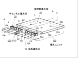
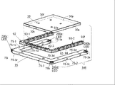
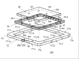
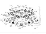
図1は本発明の第1の実施例の面光源、面照明装置の概略的な分解斜視図である。 FIG. 1 is a schematic exploded perspective view of a surface light source and a surface illumination device according to a first embodiment of the present invention.
図2は本発明の第1の実施例の面光源、面照明装置の概略的な分解平面図である。 FIG. 2 is a schematic exploded plan view of the surface light source and the surface illumination device according to the first embodiment of the present invention.
図3は図1のA-A'線に沿って切断した前記面光源、面照明装置の概略的な断面図である。 FIG. 3 is a schematic cross-sectional view of the surface light source and the surface illumination device cut along the line AA ′ in FIG.
図4は図1のB-B線に沿って切断した前記面光源、面照明装置の概略的な断面図である。 FIG. 4 is a schematic cross-sectional view of the surface light source and the surface illumination device cut along line BB in FIG.
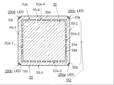
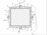
図5は前記面光源、面照明装置の概略的な平面図である。 FIG. 5 is a schematic plan view of the surface light source and the surface illumination device.
図6は前記面光源、面照明装置の概略的な底面図である。 FIG. 6 is a schematic bottom view of the surface light source and the surface illumination device.
図7は光学的チャンネル導光体の概略的な拡大斜視図である。 FIG. 7 is a schematic enlarged perspective view of an optical channel light guide.
図8は前記面光源、面照明装置の概略的な拡大部分平面図であり、導光体ユニット100の内部を通過する光線の光路の一例を示す前記面光源、面照明装置の拡大部分平面図である。
FIG. 8 is a schematic enlarged partial plan view of the surface light source and the surface lighting device, and an enlarged partial plan view of the surface light source and the surface lighting device showing an example of an optical path of a light beam passing through the inside of the
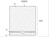
図9は前記面光源、面照明装置を液晶表示装置に適用した一例を示す概略断面図である。 FIG. 9 is a schematic cross-sectional view showing an example in which the surface light source and the surface illumination device are applied to a liquid crystal display device.
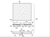
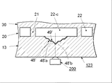
図1ないし図8に示すように、面光源、面照明装置は概略的には導光体ユニット100と少なくとも一つの発光ダイオード(LED) 200 (又は点光源)とからなる。
As shown in FIG. 1 to FIG. 8, the surface light source and the surface illumination device generally include a
用語「面光源、面照明装置」は、平面光源、サイドライト、エッジライトとも呼ばれ前記面光源、面照明装置と実質的に同等のものである。また用語「導光体」はライトガイド、導光板、光導波路、導光路と実質的に同等のものである。 The terms “surface light source and surface illumination device” are also called planar light sources, side lights, and edge lights, and are substantially equivalent to the surface light sources and surface illumination devices. The term “light guide” is substantially equivalent to a light guide, a light guide plate, an optical waveguide, and a light guide.
導光体ユニット100 は透明、光透過性、光伝達性の材料を有する実質的に少なくとも一つの透明な部材からなる。
The
前記導光体ユニット100 を構成する少なくとも一つの透明な部材として、例えば以下に列挙するポリマー、樹脂が好適に用いられるがこれらに限定されない。
As the at least one transparent member constituting the
即ち、ポリメチルメタクリート(PMMA: polymethyl-methacrylate) (屈折率、約1.49-1.50) などのアクリル樹脂、ポリカーボネート樹脂 (PC: polycarbonate) (屈折率、約1.58-1.59)、ポリスチレン樹脂 (PS: polystyrene) (屈折率、約1.59-1.60)、アクリルとポリスチレン共重合体 (屈折率、約1.51-1.57)、 ポリエチレンテレフタレート (PET: polyethylene terephthalate) (屈折率、約1.66)、エポキシ樹脂 (epoxy) (屈折率、約1.55-1.61)、 ふっ化ポリイミド樹脂 (polyimide fluoride) (屈折率、約1.46-1.47)、ポリビニリデンクロライド樹脂 (polyvinylidene chloride) (屈折率、約1.47)、シリコーン樹脂 (silicone resin) (屈折率、約1.41)、シリコーン・ゴム (SR: silicone rubber) (屈折率、1.42)、ポリテトラフルオロエチレン樹脂(PTFE: polytetrafluoroethylene) (屈折率、約1.35)。 That is, acrylic resin such as polymethyl-methacrylate (PMMA) (refractive index, approximately 1.49-1.50), polycarbonate resin (PC: recycled) (refractive index, approximately 1.58-1.59), polystyrene resin (PS: polystyrene) ) (Refractive index, approximately 1.59-1.60), acrylic and polystyrene copolymer (refractive index, approximately 1.51-1.57), polyethylene terephthalate (PET: refractive index, approximately 1.66), epoxy resin (epoxy) (refractive Rate, approximately 1.55-1.61), polyimide fluoride (refractive index, approximately 1.46-1.47), polyvinylidene chloride (refractive index, approximately 1.47), silicone resin (refractive Rate, about 1.41), silicone rubber (SR) (refractive index, 1.42), polytetrafluoroethylene (PTFE) (refractive index, about 1.35).
前記透明部材として、屈折率を目的に応じて調整可能な透明樹脂、例えば紫外線硬化エポキシ樹脂を主体とした透明樹脂を用いても良い。フッ素と硫黄を添加したエポキシ樹脂はその配合比率に従い屈折率が1.42 と1.70との間で調整可能であり、例えばNTT アドバンステクノロジ(NTT AT)から商業的に入手できる。 As the transparent member, a transparent resin whose refractive index can be adjusted according to the purpose, for example, a transparent resin mainly composed of an ultraviolet curable epoxy resin may be used. The refractive index of the epoxy resin added with fluorine and sulfur can be adjusted between 1.42 and 1.70 according to the blending ratio, and is commercially available from, for example, NTT Advanced Technology (NTT AT).
導光体ユニット100は、実質的に透明な平板状の部材からなる面照明導光部材 (面照明ライトガイド) 30と、実質的に透明な板状体又は棒状体からなる線状部材 (線状に延長した部材) 10 と、それらの間に配置された光学的チャンネル導光部材 (チャンネル・ライトガイド、光路導光体) 20とからなる。
The
即ち光学的チャンネル導光部材20は、面照明導光部材30と、線状部材10との間に横方向に挟まれている。
That is, the optical channel
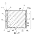
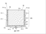
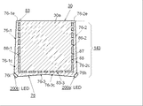
面照明導光部材30は、一般的に、面照明表面すなわち光出射表面である第1の主表面 (前面) 30aと、第1の主表面30aと対向する第2の主表面 (裏面) 30bと、第1の側面 (サイド、エッジ、端部) 30cと、第1の側面30cと対向する第2の側面30dと、第3の側面30eと、第3の側面30eと対向する第4の側面30fとからなる実質的に透明な矩形の部材から構成することができる。
The surface illumination light-guiding
第1の主表面 30aは実質的に矩形で実質的に平面的な表面とすることができる。
The first
面照明導光体30は、図1、図3、図4に示すように対向する第1、第2の主表面30a、30bの間において実質的に均一な厚さを有することができる。
As shown in FIGS. 1, 3, and 4, the surface
第2の主表面 30bは、少なくとも一つの光散乱手段50を有することができる。
The second
光散乱手段50は、そこに到達または当たった光線を散乱させ、その光線を第1の主表面 30aの方向へ再指向させる。従って光線は第1の主表面 30aから外部へ出射され、例えば図9に示す液晶表示装置(LCD) 220などの被照明体を照明する。
The light scattering means 50 scatters the light beam reaching or hitting it, and redirects the light beam toward the first
光散乱手段50は第2の主表面 30bに部分的に又は全面的に配置されることができる。また光散乱手段50は少なくとも一つの光散乱フィルム (膜又は層)、少なくとも一つの粗面、少なくとも一つの溝、および、または少なくとも一つのプリズムで構成することができる。また第2の主表面 30bの光散乱手段50が存在しない領域は平滑な面とすることができる。
The light scattering means 50 can be disposed partially or entirely on the second
光散乱手段50は第1の主表面 30aのほぼ全面にわたって均一な輝度を得るために第2の主表面 30bに所定の散乱パターンを形成することが望ましい。
It is desirable for the light scattering means 50 to form a predetermined scattering pattern on the second
図6 (および図3、図4) に示すように、複数の光散乱手段50は可変する距離を隔てて互いに平行に配列したほぼ均一な幅を持った複数のストライプ (帯)、ベルト又は線を有するグラデーション・パターン(漸次的変化模様)を構成することができる。このグラデーション・パターンは次のようにして構成できる。すなわち、複数のストライプ (帯)、ベルト又は線の数量 (本数) が、光入射部である第1の側面 30cから対向する第2の側面 30dに向かって段階的又は連続的に順次、増加するように設定する。一方、隣接するストライプ (帯)、ベルト又は線の間の間隔が第1の側面 30cから対向する第2の側面 30dに向かって段階的又は連続的に順次、減少する。光散乱手段50がそのようなグラデーション・パターンを有するので、面照明導光体30における光散乱領域を光入射側面30cから対向側面30dに向かう距離に比例して増加させることができ、面照明導光体30の光出射主表面30aから均一な輝度を持つ光線を出射できるようになる。
As shown in FIG. 6 (and FIG. 3 and FIG. 4), the plurality of light scattering means 50 are formed of a plurality of stripes (belts), belts or lines having substantially uniform widths arranged in parallel with each other at variable distances. A gradation pattern (gradual change pattern) having the following can be formed. This gradation pattern can be constructed as follows. That is, the number (number) of a plurality of stripes (bands), belts, or lines increases stepwise or continuously sequentially from the
受光、光入射部分として機能する 第1の側面30cは、チャンネル導光体20から出射、出力する光線を受光し、面照明導光体30の内部に導入する。
The
チャンネル・ライトガイド又は光学的チャンネル導光体20は、ファイバ光学の光コアとして機能する複数の光チャンネル素子21とファイバ光学の光クラッドとして機能する複数の空間 (又は介在部: インターポーザー) 22とから構成される。
The channel light guide or optical
複数の光チャンネル素子21 (コア手段) と複数の空間22 (クラッド手段) とは、交互に配置され、線状の光学的チャンネル・アレイ (光学的チャンネル整列体) を構成するように配列される。 A plurality of optical channel elements 21 (core means) and a plurality of spaces 22 (cladding means) are arranged alternately to form a linear optical channel array (optical channel alignment body). .
。
.複数の光チャンネル素子21 は隣接する二つの空間22の介在部によって分離され光学的に独立している。
.
The plurality of
チャンネル導光体 20の光出射表面20dが面照明導光体30の受光側面30cと接続、接触又は隣接し、チャンネル導光体 20の光入射表面20cが線状導光体10の前方光出射側面10dと接続、接触又は隣接するように、チャンネル導光体 20 が面照明導光体30と線状導光体10との間に横方向に挟まって配置される。
The
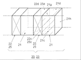
図7に示すように、チャンネル導光体 20は複数の光チャンネル素子 (又は光学的コア・チャンネル素子、光学的コア) 21 (21-1, 21-2, ・・・.及び 21n, and 21-1', 21-2',・・・及び21-n')と複数の光学的クラッド (又は介在体、空間、開口) 22 (22-c, 及び 22-1, 22-2, ・・・ 及び 22n, 及び 22-1', 22-2', ・・・22-n' 及び 22-c)とから構成される。
As shown in FIG. 7, the
そして光学的クラッド22は隣接する光チャンネル素子 (又は光学的コア) 21の間に位置し、複数の光チャンネル素子 (又は光学的コア) 21はそれぞれ光学的に孤立する。またそれぞれの光チャンネル素子21は対向する並列な壁を持っている。
The
図7において光チャンネル素子21の幅 "w!" は一定であり、光学的クラッド22の幅 "w2" は異なっている。
In FIG. 7, the width “w!” Of the
複数の光学的コア・チャンネル素子21と複数の光学的クラッド22とは、交互に実質的に平行に配列し、全体としてチャンネル導光体 20のファイバー光学的チャンネル整列体又は線状光チャンネル・アレイを構成する。
The plurality of optical
この実施形態では、光学的コア・チャンネル素子21の数量は、チャンネル導光体 20の中間 "c" からチャンネル導光体 20の対向する両端分 20e、 20fに向かう距離にほぼ比例して、チャンネル導光体 20の線状の長さに沿って可変して分布されている。
In this embodiment, the quantity of optical
隣接した光学的コア・チャンネル素子21間のピッチ (間隔) "p" 及び空間の光学的クラッド22の幅 "w2" は、チャンネル導光体 20の中心 "c" からチャンネル導光体 20の対向する両端分 20e、 20fに向って連続的又は段階的に減少するように所定のグラデーション・パターンを構成する。その中心 "c"には中心のコア空間22-c が配置され、コア空間22-c が線状導光体 10 の裏側の側面 10c の近辺に配置された点状光源 200と対面している。
The pitch (spacing) “p” between adjacent optical
従って、光学的コア・チャンネル素子21はその光出射側面20dから光学的コア・チャンネル素子21の線状の長さに沿ってほぼ均一な光線を出射することができる。
Accordingly, the optical core /
比較的高い屈折率 n1 (n1>1) を持つ光学的コア・チャンネル素子21が、チャンネル導光体20の線状のファイバー光学的アレイの長さ方向に、光学的コア・チャンネル素子21の屈折率よりも低い屈折率 n2 (n2=1) を持つ空気インターポーザー又は空気クラッド22の間に介在しているので、チャンネル導光体20内に光学的に互いに分離した複数の独立した光導波路又は固体状ライト・パイプ21 (21-1、21-2、 ・・・ 21n、及び21-1'、21-2'、 ・・・、21-n') が構成される。
The optical
光学的コア・チャンネル素子21は、図7に示すこの実施例では、ほぼ矩形の形状を有している。そして光学的コア・チャンネル素子21のそれぞれの受光表面 (最も近い端面) 21cの面積はそれぞれの光出射表面 (最も遠い端面) 21dの面積とほぼ等しい。
The optical
しかしながら、光学的コア・チャンネル素子21は、例えば対向する受光及び出射表面21c 及び 21dと対向する傾斜壁面とを有する台形などの他の形状とすることができる。
However, the optical
それぞれの光学的コア・チャンネル素子が、出射表面21dの面積を受光表面21cの面積より大きくした台形を構成する場合には、出射表面から出射する光束を受光表面に入射する光束よりも拡大することができる。
When each optical core channel element forms a trapezoid in which the area of the
そして出射表面から出射する光束の指向角度を図7に示す光学的コア・チャンネル素子21の光束の指向角度より大きくすることができる。
The directivity angle of the light beam emitted from the output surface can be made larger than the directivity angle of the light beam of the optical
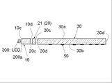
再び図1ないし図6を参照して、線状導光体10は、対向する一対の主表面10a、10bと対向する一対の前方及び後方側面10c、10dと対向する一対の端面10e、10fと後方側面10cに位置する少なくとも一つの受光部分10gと光反射手段40とからなることができる。
Referring to FIGS. 1 to 6 again, the linear
この実施例の光反射手段40は、線状導光体10の長さのほぼ中心に位置する実質的に三角形の開口 (又は貫通孔) である。更にこの開口40はほぼアルファベットの "V" 字型の形状の対向する反射面40a 、40bと反射面40a 、40bを結ぶ他の表面40cと反射面40a 、40bの交点40dとからなる。
The light reflecting means 40 of this embodiment is a substantially triangular opening (or a through-hole) located substantially at the center of the length of the linear
対向反射面40a 、40bは対向する傾斜面を有し、それらの傾斜角度は同一であり、それぞれ30から 60度であるのが望ましい。
The opposing reflecting
線状導光体10はチャンネル導光板 (チャンネル導光体<チャンネル導光部材) 20 の第1の側面20c と接続、接触又は隣接して配置することができる。
The linear
そして線状導光体10の前方側面10dからの光線は主として光学的コア・チャンネル素子21を通過できる。
Light rays from the
少なくとも一つの発光ダイオード200 (LED) が線状導光体10の受光部分10gに位置するように線状導光体10と関連して配置される。
At least one light emitting diode 200 (LED) is disposed in association with the linear
発光ダイオード200 (LED) の光出射面は光反射手段すなわち対向反射面と対面し、LED 200の光軸を対向反射面 40a、40bの交点40dと一致させている。
The light emitting surface of the light emitting diode 200 (LED) faces the light reflecting means, that is, the opposing reflecting surface, and the optical axis of the
例えばベアLEDチップ、カプセル化又はパッケージ化LEDチップ、表面実装型LED (SMD型LED) 及び周知の半円形型LED等の、いかなるタイプの発光ダイオードも本発明に使用する点状光源として使用できる。 Any type of light emitting diode can be used as a point light source for use in the present invention, for example, a bare LED chip, an encapsulated or packaged LED chip, a surface mount LED (SMD LED) and a known semi-circular LED.
青、緑及び赤色の3色の異なった色を発光する3種類のLEDベア・チップ又はLEDダイを一つのカプセル又はパッケージ内に収容し、それらの混合色である白色を出射するカプセル化又はパッケージ化LED 200を本発明の面照明装置すなわち面光源装置の点光源として用いると、フルカラーの可視情報を表示する液晶表示装置を照明することができる。
Encapsulation or package that emits three kinds of LED bare chip or LED die emitting three different colors of blue, green and red in one capsule or package and emits the mixed color white When the
その代わりに紫外線、紫色、青色などの比較的に短波長の光線を発光するLEDチップと、短波長光線を白色光に変換する蛍光体とを組み合わせた白色発光LEDが上記と同様な目的に使用できる。 Instead, a white light-emitting LED that combines a relatively short-wavelength LED chip, such as UV, purple, and blue, and a phosphor that converts short-wavelength light into white light is used for similar purposes. it can.
これらの白色発光、発光ダイオードは、例えば日亜化学工業株式会社、豊田合成株式会社、スタンレー電気株式会社、シチズン電子株式会社、星和電機製造株式会社、ルミレッズ ライティングU.S. LLS (Lumileds Lighting U.S. LLS) などから商業的に入手できる。 These white light emitting and light emitting diodes are, for example, Nichia Corporation, Toyoda Gosei Co., Ltd., Stanley Electric Co., Ltd., Citizen Electronics Co., Ltd., Seiwa Electric Manufacturing Co., Ltd., Lumileds Lighting US LLS (Lumileds Lighting US LLS), etc. Commercially available.
図8は導光体ユニット100内の光線の通路 (光路) の代表例を示す。
FIG. 8 shows a representative example of a light path (light path) in the
図8において、少なくとも一つの発光ダイオード200 (LED) が線状導光体10の受光部10gと接触、隣接又は埋設されて配置される。
In FIG. 8, at least one light emitting diode 200 (LED) is disposed in contact with, adjacent to or embedded in the
発光ダイオード200 (LED) の光出射窓 200a は実質的に三角形の開口を有する光反射手段40の対向反射面40a、40bと対面し、対向反射面40a、40bは他の面40cの水平線に対して左右対称的な傾斜角を持っている。
The
表面 (側面)は第1の屈折率 (n1>1) を持つ線状導光体10と第1の屈折よりも低い屈折率 (n2=1) を持つ開口内の空気40との境界を構成する。
The surface (side surface) forms a boundary between the linear
発光ダイオードLED 200から出射する光線 (光束) Lは線状導光体 10 内に入射し、反射手段40の方向 に進行する。
A light beam (light beam) L emitted from the light emitting
LED 200からの前記光線 "L" の内の大部分の光線 "L1" は、反射手段 40 の対向する傾斜反射面 40a、40bに到達する。
Most of the light beams “L1” out of the light beams “L” from the
内部全反射 (TTR: トータル・インターナル・リフレクション) の原理に基づいて臨界角以上で入
射した光線 "L1" は傾斜反射面40a、40bによって実質的に横方向である互いに対向する第1と
第2の方向へ反射される。
Based on the principle of total internal reflection (TTR), a light beam “L1” incident at a critical angle or more is first and second facing each other substantially in the lateral direction by the inclined reflecting
その反射光線 "L1" は内部全反射の原理に基づいて線状導光体 10 内で実質的にその長さに沿っ
て全反射を繰り返して対向する第1と第2の端面 10e、10fに向かって進行する。
Based on the principle of total internal reflection, the reflected light beam “L1” repeats total reflection substantially along its length within the linear
反射手段 40 の対向する傾斜反射面 40a、40bに全反射の臨界角より小さい角度で到達した残余の光線 "L2" は傾斜反射面 40a、40bを反射せずに通過するので、残余の光線 "L2" は傾斜反射面 40a、40bを通過して三角形の開口40と中心の空気のクラッド22-cとを経由して面照明導光体30内に伝達する。
The remaining light beam "L2" that has reached the opposing inclined reflecting
線状導光体 10から漏洩する光線を線状導光体 10へ戻すために、LED 200の受光部10bを除いて反射シート又は反射板 52を設けることができる。
In order to return the light beam leaking from the linear
チャンネル導光体素子 (即ち光学的コア素子、光学的コア) 21はそれぞれのチャンネル導光体素子の間に存在し隣接するインターポーザー (即ち介在体、この実施例では空気クラッド、光学的クラッド) 22によって分離又は光学的に孤立している。 Channel light guide elements (i.e., optical core elements, optical cores) 21 exist between adjacent channel light guide elements and are adjacent interposers (i.e., intervening bodies, in this example, air clad, optical clad). 2 2 separated or optically isolated.
そしてチャンネル導光体素子21の屈折率 (n1>1) は空気クラッド22の屈折率 (n2=1) より高い。
The refractive index (n1> 1) of the channel
光学的チャンネル素子21に入った光線 "L1" は、その中を全反射に基づいて少なくとも一回反射して光出射側面21dに向けて進行することができる。
The light beam “L1” that enters the
光線 "L1" が反射手段40で反射した後に光学的チャンネル素子21の光入射側面 (光入力面) 21cに到達したときに、光学的チャンネル素子21の屈折率が線状導光体10の屈折率と等しい (又はより高い)ので、光線 "L1"は光学的チャンネル素子21の内部に入ることができる。
When the light beam “L1” reaches the light incident side (light input surface) 21c of the
そして面照明導光体30の屈折率が光学的チャンネル素子21の屈折率と等しい (又はより高い)ので、その光線 "L1" は光学的チャンネル素子21の光出射側面 (光出射面) 21d を経由して面照明導光体30の光入射側面30cから面照明導光体30の内部に入射することができる。
Then, since the refractive index of the surface
光線 "L1 が"線状導光体 10 の後方側面 10c に到達したときに、光線 "L1" は後方側面で光学的チャンネル導光体20の方向へ反射し、光学的チャンネル素子21又は空気のインターポーザー22に到達する。
When the light beam “L1” reaches the
線状導光体 10 の後方側面 10cで反射した後に、又は反射手段 40で反射した後に全反射の臨界角以上で空気のインターポーザー 22 に到達した光線 "L1" は空気のインターポーザー 22によって反射され、実質的に横方向 (後方側面 10c又は端面 10e、10f) へ進行する。
The light beam “L1” that has reached the
線状導光体 10 の後方側面 10cで反射した後に、又は反射手段 40で反射した後に全反射の臨界角以下で空気のインターポーザー 22 に到達した光線 "L1" は空気のインターポーザー 22を通過し、面照明導光体30の光入射側面30cから面照明導光体30の内部に入射する。
The light beam “L1” that has reached the
例えば図 3 に示す光散乱手段 50と同様な光散乱手段51を後方側面10c及び、又は端面10e、10fに部分的に設けても良い。
For example, the light scattering means 51 similar to the light scattering means 50 shown in FIG. 3 may be partially provided on the
光散乱手段 50に到達した光線 "L1" は散乱し散乱光線 "L3"となる。散乱光線 "L3" は、光学的チャンネル導光体20 (光学的チャンネル素子21及び空気のインターポーザー 22)に向かって進行する。
The light beam “L1” that reaches the light scattering means 50 is scattered and becomes a scattered light beam “L3”. The scattered light "L3" travels towards the optical channel light guide 20 (
光学的チャンネル素子21に到達した散乱光線 "L3" は、その中を全反射に基づいて少なくとも一回反射して進行し、そこを通過し光入射側面 30c を経由して面照明導光体 30 に入る。
The scattered light “L3” that has reached the
全反射の臨界角以上で空気クラッド (空気のインターポーザー21) に到達した散乱光線 "L3" は、全反射に基づいて反射し、線状導光体 10 の中でそのほぼ横方向に進行する。一方、全反射の臨界角より以下の角度で空気クラッド (空気のインターポーザー) 21 に到達した散乱光線 "L3" はそこを通過し光入射側面 30c を経由して面照明導光体 30 に入る。
The scattered light "L3" that has reached the air cladding (air interposer 21) above the critical angle of total reflection is reflected based on total reflection and travels almost horizontally in the linear
端面に到達した光線 "L1" はその平面部 (平滑部)で反射し、または散乱手段55で散乱し散乱光線 "L3" となる。 The light beam “L1” that reaches the end face is reflected by the flat surface portion (smooth portion) or scattered by the scattering means 55 to become a scattered light beam “L3”.
その光線 "L1" は線状導光体 10 内を実質的に横方向でその反対方向に進行し、また散乱光線 "L3" は線状導光体 10 内を多数の方向に進行する。
The light beam “L1” travels substantially in the transverse direction in the linear
線状導光体 10 の後方側面10c又は端面10e、10fから漏洩した光線 "L1" 又は散乱光線 "L3" は反射又は散乱シート又は板52によって反射又は散乱され、線状導光体 10に戻る。
The light beam “L1” or scattered light beam “L3” leaked from the
光学的コア・チャンネル導光体21に到達する全ての光線L1はその内部に入ることができ、一方、空気クラッド22に全反射の臨界角以下の角度で到達する光線L1のみがその内部に入ることができ、空気クラッド22に全反射の臨界角より大きい角度で到達する光線L1は線状導光体内で反射して空気クラッド22を通過しないので、光学的コア・チャンネル導光体21内に入射することができる第一の光線L1の量は、空気クラッド22の内に入射することができる第二の光線L1の量より多いことに留意すべきである。
All rays L1 that reach the optical core
光学的コア・チャンネル導光体21からは比較的に大量の第一の光線が出射し、また光ファイバーと同様に広い拡散角で出射するが、一方、空気クラッド22から比較的に少量の第二の光線が出射する
A relatively large amount of the first light beam is emitted from the optical core
光チャンネル導光体 (ファイバー光学的線状アレイ) 20 はその出射面からその長さに沿って第一と第二の強弱の光線を隣接して出射し、第一と第二の強弱の光線が面照明導光体の受光側面から入射する。 The optical channel light guide (fiber optical linear array) 20 emits first and second strong and weak light beams adjacent to each other along its length from its emission surface, and the first and second strong and weak light beams. Enters from the light receiving side of the surface illumination light guide.
この第一と第二の強弱の光線が面照明導光体内の受光側面の近辺で混合し、それによりほぼ均一化した輝度の線状光線を面照明導光体内に伝達できる。 The first and second strong and weak light beams are mixed in the vicinity of the light-receiving side surface in the surface illumination light guide, whereby a linear light beam with substantially uniform brightness can be transmitted into the surface illumination light guide.
面照明導光体内のほぼ均一化した輝度の線状光線は、全反射に基き対向主表面間を繰り返して反射しながら受光側面と対向する側面に向かって伝達し、その途中でこの伝達光線が光出射主表面から徐々に出射する。 The linear light beam with almost uniform brightness in the surface illumination light guide is transmitted toward the side opposite to the light receiving side while repeatedly reflecting between the opposing main surfaces based on total reflection, and this transmitted light is transmitted along the way. The light exits gradually from the main surface.
従って、面照明導光体の光出射主表面のほぼ全面にわたってほぼ均一な平面光線を得ることができる。 Therefore, a substantially uniform plane light beam can be obtained over substantially the entire light output main surface of the surface illumination light guide.
以上に記述したように、この実施例では、チャンネル導光体 20の光学的チャンネル導光体素子 (光学的コア・チャンネル素子) 21及び、又はインターポーザー (光学的クラッド) 22はグラデーション・パターンを有する全体として線状のファイバー光学的アレイ20を構成し、光学的チャンネル導光体素子 21のピッチ "p" 及び、又はインターポーザー 22の幅 "W2" が変化して分布しているので、チャンネル導光体 20 は線状のファイバー光学的アレイ 20 の長手方向に沿ってほぼ均一な光出力を得ることができる。
As described above, in this embodiment, the optical channel light guide element (optical core channel element) 21 and / or the interposer (optical clad) 22 of the
その結果、面照明光体 30 の光出射表面 30aのほぼ全面にわたってほぼ均一な面照明を得ることができる。
As a result, substantially uniform surface illumination can be obtained over almost the entire
図 9 は図 1 のA-C線に沿う第1の実施例の概念的な拡大、部分断面図であり、本発明の代表的な応用例を示す。 FIG. 9 is a conceptual enlarged, partial sectional view of the first embodiment along the line A-C in FIG. 1, and shows a typical application example of the present invention.
図 9に示すように、導光体ユニット100と発光ダイオード(LED) 200とからなる面光源、面照明装置は、代表的には液晶表示装置 (LCD) 220のバックライトなどの面照明に用いられる。このバックライトにより、観察者はLCD 200の裏面に配置された面照明導光体30によって照明されたLCD 220の映像表示を見ることができる。
As shown in FIG. 9, a surface light source and a surface illumination device composed of a
以上で詳細に記述したように、導光体ユニット100は、要約すると対向する主表面10a 、10bと受光側面10cと光出射側面10dと反射手段40とを有する線状導光体10と、受光側面20cと光出射面20dとを有する光学的チャンネル導光体20と、面照明前面30aと対向裏面30bと裏面30bに配置された光散乱手段50とからなる。
As described in detail above, the
液晶表示装置(LCD) 220は、要約するとそれぞれの内面に形成された透明電極膜を有する対向する一対の透明板と両透明板間に充填された液晶材料を有する液晶パネル221と、液晶パネル221を挟むように配置された対向する一対の偏光フィルム222、 223とからなる。
In summary, the liquid crystal display device (LCD) 220 includes a pair of opposed transparent plates having transparent electrode films formed on the inner surfaces thereof, a
光拡散又はプリズム シート51を面照明導光体 30 の面照明表面30aの上または近辺に配置しても良く、また光反射シート又は板54を面照明導光体 30 の裏面30bの上または近辺に配置しても良い。
The light diffusing or
光反射又は光遮断シート53を面照明導光体 30 の表面 30a の終端部、線状導光体10の表面10aとチャンネル導光体20の表面とを覆うように配置しても良い。なお図9 では空気クラッド (空気のインターポーザー) 22のみが示され、光学的コア・チャンネル素子 21 は示されていない。
The light reflection or
光反射又は光遮断シート53は、導光体ユニット100の表面から不本意に漏れた光線を元に戻すか、導光体ユニット100の内部に外部から入る光線を遮蔽する。
The light reflection or
その代わりに、この面光源は液晶表示装置220の (図9には示されていない) フロントライト用に用いることができる。
Instead, this surface light source can be used for the front light (not shown in FIG. 9) of the
この場合には、光反射シート又は板54を取り除き、観察者は面照明導光体 30 経由して液晶表示装置220を見る。
In this case, the light reflecting sheet or
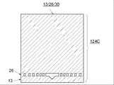
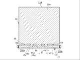
図10、図11及び図12は、導光体ユニット 100の平面図であり、第1実施例の三つのタイプの導光体ユニット 100 (100A、100B、100C) を示す。
10, 11 and 12 are plan views of the
図10に示すように、第1のタイプの導光体ユニット100Aは、面照明導光体30と、反射手段40を有する線状導光体10とチャンネル導光体20とを接続又は一体化して統合した複合導光体 (10, 20) とからなる。
As shown in FIG. 10, the first type of
そして面照明導光体30は複合導光体 (10, 20) と横方向に接触して配置するのが望ましい。
The surface
複合導光体 (10, 20) の線状導光体部分10から複合導光体 (10, 20) におけるチャンネル導光体部分20の光学的コア・チャンネル素子21に入射した光線は、その内部で一回以上全反射しその光出射端面21dに向かってその内部を進行することができる。
The light beam incident on the optical
その光線は光出射端面21dから効率的に出射し、受光側面30cから入射し面照明導光体30の内部を伝達する。
The light beam is efficiently emitted from the light emitting
複合導光体 (10, 20)と面照明導光体 30 とは実質的に透明なポリマー材料からなるのが望ましい。複合導光体 (10, 20)の屈折率は面照明導光体 30の屈折率より高くするのが望ましい。
The composite light guide (10, 20) and the surface
例えば、複合導光体 (10, 20) として用いられる実質的に透明なポリマー材料としては屈折率約1.49-1.50を有するポリメチル・メタアクリレート (PMMA) 又は屈折率約1.58-1.59を有するポリカーボネート (PC)を用い、面照明導光体 30 として用いられる実質的に透明なポリマー材料としては前記PMMAを用いることができる。
For example, the substantially transparent polymer material used as the composite light guide (10, 20) may be polymethyl methacrylate (PMMA) having a refractive index of about 1.49-1.50 or a polycarbonate having a refractive index of about 1.58-1.59 (PC PMMA can be used as a substantially transparent polymer material used as the surface
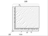
図11に示すように、第2のタイプの導光体ユニット100Bは、反射手段40を有する線状導光体10と、面照明導光体30とチャンネル導光体20とを接続又は一体化して統合した複合導光体 (20, 30) とからなる。
As shown in FIG. 11, the second type of
線状導光体10は複合導光体 (20, 30)と横方向に接触して配置するのが望ましい。
The linear
複合導光体 (20, 30)と線状導光体10は、好ましくは共に実質的に透明なポリマー材料からなる。
Both the composite light guide (20, 30) and the linear
複合導光体 (10, 20)の屈折率は線状導光体10の屈折率と同じか又はより高い。
The refractive index of the composite light guide (10, 20) is the same as or higher than the refractive index of the linear
複合導光体 (20, 30)と線状導光体10は、好ましくは共に実質的に透明なポリマー材料からなる。
Both the composite light guide (20, 30) and the linear
複合導光体 (10, 20)の屈折率は線状導光体10の屈折率と同じか又はより高い。例えば、複合導光体 (20, 30) は "PMMA" 又は "PC" からなり、線状導光体10は前記 "PMMA" からなることができる。
The refractive index of the composite light guide (10, 20) is the same as or higher than the refractive index of the linear
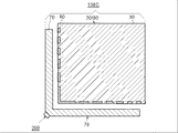
図12に示すように、第三のタイプの導光体ユニット(10, 20, 30) は面照明導光体30, チャンネル導光体20及び線状導光体10が、これらの順序で接続または一体化された唯一の複合導光体からなる。
As shown in FIG. 12, the third type of light guide unit (10, 20, 30) has a planar
導光体ユニット100C即ち複合導光体ユニット(10, 20, 30)は好ましくは実質的に透明なポリマー材料からなり、唯一の屈折率を持つ完全に統合化された唯一のユニットなので、前記導光体ユニット100A、100Bと異なって屈折率の組み合わせに関して何ら留意の必要がない。
The light guide unit 100C or composite light guide unit (10, 20, 30) is preferably made of a substantially transparent polymer material and is the only fully integrated unit with a single refractive index, so Unlike the
従って、唯一のポリマー材料からなる導光体ユニット100Cは一度に射出成型法により製造できる。 Therefore, the light guide unit 100C made of only one polymer material can be manufactured at a time by the injection molding method.
図 10に示す複合導光体ユニット(10, 20)、 図 11に示す複合導光体ユニット (20, 30) 及び図 12に示す複合導光体ユニット(10, 20, 30)は、実質的に透明なポリマーを用いて種々の製法で、例えば、レーザー切断法、射出成型法、注型成型法、圧縮成型法などによって製造することができる。 The composite light guide unit (10, 20) shown in FIG. 10, the composite light guide unit (20, 30) shown in FIG. 11, and the composite light guide unit (10, 20, 30) shown in FIG. Further, it can be produced by various production methods using a transparent polymer, for example, by a laser cutting method, an injection molding method, a cast molding method, a compression molding method or the like.
レーザー切断法はレーザー切断又は彫刻機を用い、導光板に少なくともチャンネル導光体 20 と対応した所定のパターンに従ってレーザー・ビームのエネルギーを走査処理することによって行われる。
The laser cutting method is performed by using a laser cutting or engraving machine and scanning the energy of the laser beam in accordance with a predetermined pattern corresponding to at least the
射出成型法は少なくともチャンネル導光体 20と対応したチャンネル・パターンと反射手段 40 と対応した反射手段パターンとを含む成型パターンを持ったモールド型を用い、モールド型の内部に溶融した又は軟化したポリマーを射出し、冷却後に固体化したポリマー導光体 (図 10 の参照符号 (10, 20) )、(図 11の参照符号(20, 30) )、(図 12の参照符号 (10, 20,30) )をモールド型から取り出すものである。
The injection molding method uses a mold having a molding pattern including at least a channel pattern corresponding to the
注型成型法又は樹脂重合法はチャンネル導光体 20と対応したチャンネル・パターンと反射手段 40と対応した反射手段パターンとを含む成型パターンを持った注入型を用い、熱硬化性硬化剤又は感光性硬化剤を含む液体樹脂又はモノマーを注入型に注いで熱又は光の硬化条件を与え、硬化後に注入型から重合して高分子化した固体化ポリマー導光体 (図 10 の参照符号 (10, 20) )、(図 11の参照符号(20, 30) )、(図 12の参照符号 (10, 20,30) )をモールド注入型から取り出すものである。
The casting molding method or the resin polymerization method uses an injection mold having a molding pattern including a channel pattern corresponding to the
圧縮成型法は少なくともチャンネル導光体 20と対応したチャンネル・パターンと反射手段 40 と対応した反射手段パターンとを含む成型パターンを持ったモールド型を用い、モールド型に溶融した又は軟化したポリマーを配置し、モールド型を加圧圧縮し、冷却後に固体化したポリマー導光体 (図 10 の参照符号 (10, 20) )、(図 11の参照符号(20, 30) )、(図 12の参照符号 (10, 20,30) )をモールド型から取り出すものである。
The compression molding method uses a mold having a molding pattern including at least a channel pattern corresponding to the
導光体ユニット100A, 100B 又は100Cを上記の製法によって製造すると、それらを簡単に大量生産することができ、導光体ユニット100A, 100B又は100Cを比較的に短納期及び低コストで提供できる。
When the
図13、図14及び図15を参照して、これらの図は第1の実施例の概念的な底面図であり、図6における面照明導光体30の光散乱手段50の散乱パターンの三種類の変形例を示す。
Referring to FIG. 13, FIG. 14 and FIG. 15, these drawings are conceptual bottom views of the first embodiment. Three scattering patterns of the light scattering means 50 of the surface
図13 (及び図3、図4) に示すように、第2の主表面 (裏面) 30bに設けられた複数の光散乱手段は、複数の点又は点状領域からなりグラデーション・パターンを形成している。 As shown in FIG. 13 (and FIG. 3, FIG. 4), the plurality of light scattering means provided on the second main surface (back surface) 30b are composed of a plurality of points or dot-like regions to form a gradation pattern. ing.
複数の点又は点状領域 50aのそれぞれは図示した円形 (又は楕円形、矩形、多角形) などのほぼ等しい面積を有する任意の形状をしている。
Each of the plurality of points or dot-
点又は点状領域50aの数量は、受光側面30cから対向側面30dに向かう距離に従って、点又は点状領域50aの分布密度が段階的又は連続的に増加している。
The number of the dots or dot-
従って面照明導光体30の面照明表面30aの実質的に全ての領域にわたってほぼ均一な表面輝度を得ることができる。
Accordingly, a substantially uniform surface brightness can be obtained over substantially the entire region of the
図14及び図15 (及び図3及び図4) に示すように、第2の主表面に配置された複数の光散乱手段50b、50cは多数の島状領域 (又は孤立領域) からなり、グラデーション・パターンを構成することができる。 As shown in FIGS. 14 and 15 (and FIGS. 3 and 4), the plurality of light scattering means 50b and 50c arranged on the second main surface are composed of a number of island-like regions (or isolated regions), and gradation -Patterns can be configured.
それぞれの島状領域50b、50cは、例えば図14では矩形パターンを有する光散乱手段50bであり、図15では円形パターンを有する光散乱手段50bであるような任意の形状を有し異なる大きさの領域からなることができる。
Each of the island-
点又は点状領域50aの数量は、受光側面30cから対向側面30dに向かう距離に従って、点又は点状領域50aの分布密度が段階的又は連続的に増加している。
The number of the dots or dot-
島状領域50b、50cの大きさは、受光側面30cから対向側面30dに向かって段階的又は連続的に増加している。従って面照明導光体30の面照明表面30aの実質的に全ての領域にわたってほぼ均一な表面輝度を得ることができる。
The sizes of the island-
(第2の実施形態、第2実施例) (Second Embodiment, Second Example)
本発明の第2の実施例を図16ないし図19を参照して説明する。 A second embodiment of the present invention will be described with reference to FIGS.
図16は本発明の第2実施例の面光源、面照明装置の概略的な分解斜視図である。 FIG. 16 is a schematic exploded perspective view of a surface light source and a surface illumination device according to the second embodiment of the present invention.
図17は前記面光源、面照明装置の概略的な分解平面図である。図18は前記面光源、面照明装置の概略的な平面図である。 FIG. 17 is a schematic exploded plan view of the surface light source and the surface illumination device. FIG. 18 is a schematic plan view of the surface light source and the surface illumination device.
図19は光学的チャンネル導光体23の概略的な拡大斜視図である。
FIG. 19 is a schematic enlarged perspective view of the optical
第2実施例 (図16ないし図19) は、第1実施例 (例えば図1ないし図15) と光学的チャンネル導光体23と線状導光体12の構成が異なり、同様な要素、部分には同じ参照符号を付してある。従って同じ参照符号を付した要素、部分の記述は以後、省略することがある。
The second embodiment (FIGS. 16 to 19) differs from the first embodiment (for example, FIGS. 1 to 15) in the configuration of the optical
面光源、面照明装置は導光体ユニット110と点光源として少なくとも一つの発光ダイオード(LED) 200からなる。
The surface light source and the surface illumination device include a
導光体ユニット110は、面照明導光部材30と線状導光部材10 とそれらの間に配置された光学的チャンネル導光部材 23とからなる。
The
面照明導光部材30、線状導光部材10、光学的チャンネル導光部材 23は、実質的に透明な導光部材からなる。
The surface illumination
面照明導光部材30と光学的チャンネル導光部材23と線状導光部材12とは、光学的チャンネル導光部材23が面照明導光部材30と線状部材10との間に横方向に挟まれるように、これらの順序で配置される。
The surface illumination
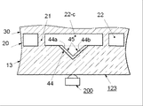
線状導光体12は、線状に延長した実質的に透明板からなり、前記透明板は対向する一対の主表面12a、12bと対向する一対の前方及び後方側面12c、12dと対向する一対の端面12e、12fと後方側面12cに位置する少なくとも一つの受光部分12gとほぼ三角形の光反射手段42と光反射手段42内のほぼ三角形の空間に配置されたほぼ透明な部材43とからなることができる。
The linear
この実施例の光反射手段又は反射体42は、ほぼ "V" 字形状を有する対向した傾斜面42a、42bと傾斜面42a、42bを接続する他の一面42cと例えば図1で参照符号40を付した実質的に三角形の開口 (又は貫通孔) に充填されたほぼ三角形の形状で、ほぼ透明なポリマー部材43からなることができ、その光反射手段42は線状導光体12の長さのほぼ中心部内に位置することができる。
In this embodiment, the light reflecting means or
透明なポリマー部材43の屈折率は線状導光体12の屈折率より低くすべきであり、それによって、全反射の臨界角以上の光線が対向傾斜面42a、42bに到達するときに。光線がポリマー部材43内に入ることなく、対向傾斜面42a、42bはその光線を線状導光体12内に反射できる。
The refractive index of the
点状光源として発光ダイオード200 (LED) が線状導光体12の後方側面の中央 "c" の近くの一部にある受光部分12gに、発光ダイオード200 (LED) の光出射面が光反射手段42の対向反射面42a、42cと対面するようにして、配置される。
The light emitting diode 200 (LED) as a point light source is reflected on the
チャンネル導光体 23は光学的コアの機能を有する複数の光チャンネル素子 21と光学的クラッドの機能を有する複数の固体インターポーザー (介在体) 25とから構成される。
The
固体インターポーザー又は光学的固体クラッド25は、隣接する光チャンネル素子 又は光学的固体コア 21の間に位置する。
A solid interposer or optical
光学的固体クラッド25と光学的固体コア 21とは交互にほぼ並行に整列して配置され、線状のファイバー光学的アレイ(整列体) を構成する。
The optical solid clad 25 and the optical
従って、複数の光学的固体コア 21は、チャンネル導光体、即ち線状のファイバー光学的アレイ23の長さ方向で、複数の光学的固体コア 21によって互いに光学的に孤立し分離される。
Accordingly, the plurality of optical
図19に示すように、この実施例では、複数の光学的コア・チャンネル素子21は実質的に同一な幅 "w1" を有している。そして複数の光学的コア・チャンネル素子21はその数量又は分布密度が、チャンネル導光体 23の中間 "c" からチャンネル導光体 23の対向する両端分 23e、 23fに向かう距離にほぼ比例して、チャンネル導光体 23の線状の長さに沿って増加するように可変して分布されている。
As shown in FIG. 19, in this embodiment, the plurality of optical
隣接した光学的コア・チャンネル素子21間のピッチ (間隔) "p" 及び固体クラッド・インポーザー25の幅 "w2" は、チャンネル導光体 23の中心 "c" からチャンネル導光体 23の対向する両端面 23e、 23fに向って連続的又は段階的に減少するように所定のグラデーション・パターンを構成する。
The pitch (spacing) “p” between adjacent optical
この構成により、チャンネル導光体 23の長さに沿ってその光出射側面21dからほぼ均一な線状の光出力を得ることができる。
With this configuration, a substantially uniform linear light output can be obtained from the light emitting
固体クラッド・インポーザー25の屈折率は光学的コア・チャンネル素子21の屈折率より低くなければいけない。
The refractive index of the solid clad
比較的に低い屈折率を有する固体クラッド・インポーザー25は、例えば、シリコーン樹脂 (silicone resin) (屈折率、約1.41)、フッ化ポリイミド樹脂 (polyimide fluoride) (屈折率、約1.46-1.47)、ポリビニリデンクロライド樹脂 (polyvinylidene chloride) (屈折率、約1.47)、フッ素と硫黄を添加した屈折率が調整可能なエポキシ樹脂 (調整した屈折率、約1.42-1.48) などのほぼ透明な樹脂から選択できる。
Solid
一方、比較的に高い屈折率を有する光学的コア・チャンネル素子21は、例えば、ポリメチルメタアクリート (PMMA: polymethyl-methacrylate) (屈折率、約1.49-1.50) などのアクリル樹脂、ポリカーボネート樹脂 (PC: polycarbonate) (屈折率、約1.58-1.59)、ポリスチレン樹脂 (PS: polystyrene) (屈折率、約1.59-1.60)、エポキシ樹脂 (epoxy) (屈折率、約1.55-1.61)、屈折率が調整可能な前記エポキシ樹脂 (調整した屈折率、約1.49-1.70) などのほぼ透明な樹脂から選択できる。
On the other hand, the optical core /
光学的チャンネル素子 (光学的コア) 21が、チャンネル導光体23の長さ方向で、対向する光入射面 (最も近い端面) 21cと光出射面 (最も遠い端面) 21dとを除いて、屈折率 "n2" を持つ光学的チャンネル素子21の屈折率よりも低い屈折率 "n4" を持つインターポーザー (光学的クラッド) 25の間に介在しているので、チャンネル導光体23内に光学的に互いに分離した複数の独立した光導波路又は固体状ライト・パイプが構成される。
The optical channel element (optical core) 21 is refracted in the length direction of the
図16に示すように、光学的コア・チャンネル素子21はほぼ矩形の形状を有している。そして光学的コア・チャンネル素子21のそれぞれの受光面 21cの面積はそれぞれの光出射面 21dの面積とほぼ等しい。
As shown in FIG. 16, the optical
しかしながら、光学的コア・チャンネル素子21は、例えば対向する受光及び出射面21c 及び 21dと対向する傾斜壁面とを有する台形などの他の形状とすることができる。
However, the optical core /
更に光学的コア・チャンネル素子21の各出射面21dの面積を対向する受光面21cより大きくすることができ、一方、インターポーザー25は光学的コア・チャンネル素子21と逆である。従って受光面21cから入射する光線は出射面21dから指向角度を拡大して出射する。
Furthermore, the area of each emitting
固体インターポーザーの内部に複数の光散乱粒子を分散してもよい。光散乱粒子は、ガラス、ポリマーなどの屈折率が固体インターポーザーと異なるほぼ透明なビーズ、光散乱性又は光反射性の顔料などから選択する。 A plurality of light scattering particles may be dispersed inside the solid interposer. The light scattering particles are selected from substantially transparent beads such as glass and polymer that have a refractive index different from that of the solid interposer, light scattering or light reflecting pigments, and the like.
固体インターポーザーに光散乱粒子を混入することにより、光線が固体インターポーザー内に入ったときに、そこから広角の散乱光線を出射できる。 By mixing light scattering particles into the solid interposer, when the light enters the solid interposer, a wide angle scattered light can be emitted therefrom.
図20ないし図23は、導光体ユニット 110 の平面図であり、第2実施例の4つのタイプの導光体ユニット 110A、 110B、 100C 及び110D を示す。
20 to 23 are plan views of the
図20,に示すように、第1のタイプの導光体ユニット110Aは、面照明導光体30と、チャンネル導光素子21とインターボーザー25とを有するチャンネル導光体23と、反射手段40と反射手段42の開口に充填されたほぼ透明なポリマー部材43とを有する線状導光体12とからなり、全ての導光部材30、21、12が互いに分離して配置されている。
As shown in FIG. 20, the first type of
導光部材30、23、12はこれらの順序で横方向に並んで互いに接触して配置されるのが望ましい。
The
即ち、チャンネル導光体23は面照明導光体30の受光側面30cと線状導光体12の出射面12dとの間に横方向に挟まれる。
That is, the
図21に示すように、第2タイプの導光体ユニット110Bは、面照明導光体30と、反射手段42と反射手段42の開口に充填されたほぼ透明なポリマー部材43とを有する線状導光体12とチャンネル導光体23とを接続又は一体化して統合した複合導光体 (12, 23) とからなる。
As shown in FIG. 21, the second type light guide unit 110B is a linear shape having a surface
面照明導光体30と複合導光体 (12, 23) とは互いに分離している。
The surface
複合導光体 (12, 23) は、複合導光体 (12, 23) の出射面23dが面照明導光体30の受光側面30cと対面するように、面照明導光体30と接触して配置することができる。
The composite light guide (12, 23) is in contact with the surface
図22に示すように、第3のタイプの導光体ユニット110Cは、反射手段42と反射手段42の開口に充填されたほぼ透明なポリマー部材43とを有する線状導光体12と、面照明導光体30とチャンネル導光体素子21とインターポーザー25とを有するチャンネル導光体23とを接続又は一体化して統合した複合導光体 (23, 30) とからなる。
As shown in FIG. 22, the third type of light guide unit 110C includes a linear
複合導光体 (23, 30) は、線状導光体12の出射面12dが複合導光体 (23, 30) のチャンネル導光体素子部分の受光側面23dと接触して配置することができる。
The composite light guide (23, 30) may be arranged such that the
図23に示すように、第3のタイプの導光体ユニット110Dは、面照明導光体30と、チャンネル導光体素子21とインターポーザー25とを有するチャンネル導光体23と、反射手段42と反射手段42の開口に充填されたほぼ透明なポリマー部材43とを有する線状導光体12とが完全に一体化した複合導光体110D又は (12, 23, 30) とからなり、全ての導光体30、23及び12がこれらの順序で互いに接続され、即ち唯一のユニットとして統合されている。
As shown in FIG. 23, the third type of light guide unit 110D includes a surface
図29は、前述の第1実施例、第2実施例のチャンネル導光部材20、23を示す拡大部分斜視図である。
FIG. 29 is an enlarged partial perspective view showing the channel
図29に示すように、光学的チャンネル導光部材20、23は、チャンネル導光素子10、23とインターポーザー22、25とからなり、両者が交互に配列されてファイバー光学的線状アレイを構成する。そしてチャンネル導光素子21とインターポーザー22、25とは、矩形の形状を持っている。
光学的コア又はライト・パイプとして機能するチャンネル導光素子21は、それぞれほぼ矩形の光入射側面21cと、入射側面と対向し入射側面と並列なほぼ矩形の光出射側面21dと、ほぼ矩形の第1の側壁21gと、第1の側壁と対向し第1の側壁と並行なほぼ矩形の第2の側壁21eと、互いに対向し並列なほぼ矩形の頂面と底面とからなり、光入射側面21cと光出射側面21dの面積はほぼ等しい。
As shown in FIG. 29, optical channel
Each of the channel
光学的クラッド又はライト・パイプのクラッドとして機能する空気又は固体のインターポーザー 22 、25は、それぞれほぼ矩形の第1の側面22c or 25cと、第1の側面22c 又は 25cと並行に対向するほぼ矩形の第2の側面22d or 25dと、互いに対向し並列なほぼ矩形の側面と、互いに対向し並列なほぼ矩形の頂面と底面とからなり、前記対向側壁はチャンネル素子21の側壁21g、21hと共通な部分である。
Air or
例えば図1、図16に示す線状導光部材10、12の内部を伝達する光線が光学的チャンネル素子21の光入射面21cに到達する時に、その光線は光学的チャンネル素子21の内部に入り内部全反射に基づいて側壁21g、21h及び、又は頂面、底面で少なくとも一回反射し光出射側面21dから出射する。
For example, when a light beam transmitted through the linear
線状導光部材10、12の内部を伝達する光線がクラッド・インターポーザー 22 、25の第1の側面22c、25cに到達する時に、内部全反射の臨界角以上の角度を持った光線はクラッド・インターポーザー 22 、25によって第1の側面22c、25cで線状導光部材10、12に戻るように反射され、クラッド・インターポーザー 22 、25内には入らない。一方、内部全反射の臨界角より以下の角度を持った光線は第1の側面22c、25cからクラッド・インターポーザー 22 、25内に入り、第2の側面22d、25dから出射する。
When the light beam transmitted through the linear
従って、光学的チャンネル素子21の光入射側面21cに到達したほとんどの光線は光学的チャンネル素子21を効率的に通過して光出射側面21dから出射する。クラッド・インターポーザー 22 、25の第1の側面22c、25cに到達した光線はその一部がクラッド・インターポーザー 22 、25を通過して第2の側面22d、25dから出射し、残余の光線は線状導光部材に戻りその内部を伝達する。
Therefore, most of the light rays that have reached the light
(第3の実施形態、第3実施例) (Third embodiment, third example)
本発明の第3の実施例を概略的斜視図である図24を参照して説明する。 A third embodiment of the present invention will be described with reference to FIG. 24 which is a schematic perspective view.
第3の実施例の面光源、面照明装置は、例えば図1ないし図4を参照して記述した第1の実施例の一つの変形を示す。第3の実施例における面照明導光体32は、第1の実施例における面照明導光体30と異なるが、第1、第3の実施例において同一な参照符号を付してある線状導光体10とチャンネル導光体20とは共に同じものである。
The surface light source and the surface illumination device of the third embodiment show one modification of the first embodiment described with reference to FIGS. 1 to 4, for example. The surface
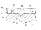
図24に示すように、面光源、面照明装置は概略的には導光体ユニット120と点光源として少なくとも一つの発光ダイオード(LED) 200とからなる。導光体ユニット120は、その中にほぼ三角形の反射手段40を有する線状導光部材10と、複数の光学的チャンネル素子 (光学的コア) 20と複数の開口又は空気インターポーザー 21 (光学的空気クラッド) とを有する光学的チャンネル導光部材 20と、面照明導光部材 32とからなる。この実施例では、面照明導光部材 32は、ほぼ平面的な面照明用第1主表面 (前面) 30aと、第1主表面と対向しテーパー状 (楔形状)の、即ち傾斜した第2主表面 (裏面) 30b又は30b'と、受光側面である第1の側面 30cと、第1の側面30cと対向する第2の側面30dと、第3の側面30eと、第3の側面30eと対向する第4の側面30fとからなる実質的に透明なほぼ矩形の部材から構成される。
As shown in FIG. 24, the surface light source and the surface illumination device generally include a
面照明導光部材 32は変化する厚さを持ち、第一のタイプの面照明導光部材 32では、図24で連続線として示す段階的なテーパー状の第2主表面32bを備えている。そのために面照明導光部材 32の厚みは、受光側面32cから対向する側面32dに向かって段階的に減少するように変化する。一方、例えば図1ないし図4に示す面照明導光部材30は、ほぼ全ての部分でほぼ均一な厚みを持っている。
The surface illumination
その代わり、第一のタイプの面照明導光部材 32では、図24で点線として示す連続的なテーパー状の第2主表面32b'を備えている。そのために面照明導光部材 32の厚みは、受光側面32cから対向する側面32dに向かって連続的に順次減少するように変化する。
Instead, the first type surface illumination
テーパー状の表面32b 又は32b'の存在により、光出射表面32aに到達する光線は受光側面32cから対向する側面32dに向かう距離に従って全反射の臨界角が狭められるので、光線が前記距離に従って光出射表面32aからより多く漏洩するようになる。そのために、例えば図6に示す光散乱手段50は必ずしも必要としない。
Due to the presence of the tapered surface 32b or 32b ', the light beam reaching the light output surface 32a has its critical angle of total reflection narrowed according to the distance from the light receiving
空気クラッド22は例えば図7、図10に示すように固体クラッドと置換してもよく、その場合、空気クラッド22の開口又は空間に光学チャンネル素子21の屈折率より低い屈折率を持つほぼ透明なポリマーを充填する。
The air clad 22 may be replaced with a solid clad as shown in FIGS. 7 and 10, for example. In that case, the air clad 22 has an opening or space that is substantially transparent and has a refractive index lower than that of the
(第4の実施形態、第4実施例) (Fourth embodiment, fourth example)
本発明の第4の実施形態を図25ないし図28を参照して説明する。 A fourth embodiment of the present invention will be described with reference to FIGS.
図25は本発明の第4の実施形態の面光源、面照明装置の概略的な分解斜視図である。 FIG. 25 is a schematic exploded perspective view of a surface light source and a surface illumination device according to a fourth embodiment of the present invention.
図26は前記面光源、面照明装置の概略的な分解平面図である FIG. 26 is a schematic exploded plan view of the surface light source and the surface illumination device.
図27は前記面光源、面照明装置の概略的な平面図である。 FIG. 27 is a schematic plan view of the surface light source and the surface illumination device.
図28は光学的チャンネル導光体26の概略的な拡大斜視図である。
FIG. 28 is a schematic enlarged perspective view of the optical
既に詳細に記述した実施例と同じ参照符号を付けた部分又は要素に関しては、この実施例では重複した記述は出来るだけ省略する。 With respect to the parts or elements having the same reference numerals as those of the embodiment already described in detail, duplicate descriptions are omitted as much as possible in this embodiment.
第4実施例の面光源装置は、導光体ユニット121とLED 200とからなる。
The surface light source device of the fourth embodiment includes a
導光体ユニット121は、その中心近辺に配置された対向反射面を持つ三角形の反射手段を有する線状導光部材(線状に延長した導光体)10 と、面照明導光部材 30と、複数のコア・チャンネル素子27と複数の空気クラッド28とを有する光学的チャンネル導光部材26とからなる。
The
光学的チャンネル導光部材26は、線状導光部材10と面照明導光部材 30との間に横方向に互いに接触又は接続して配置される。
The optical channel
図28に示すように、チャンネル導光体 26は複数の光チャンネル素子 (固体コア) 27 (27-1、27-2、・・・、27n及び 27-1'、 27-2'、・・・、27-n')と複数の 空気インターポーザー (空気クラッド) 28 (28-c、28-1、28-2、・・・、28-n、及び28-7'、28-2'、・・・、28-n'、 28-c)とから構成される。
As shown in FIG. 28, the
空気インターポーザー (光学的クラッド) 28は隣接する光チャンネル素子 (光学的コア) 27の間に位置し、複数の光チャンネル素子 (又は光学的コア) 27はそれぞれ光学的に孤立する。 The air interposer (optical cladding) 28 is positioned between adjacent optical channel elements (optical cores) 27, and the plurality of optical channel elements (or optical cores) 27 are optically isolated from each other.
光チャンネル素子 (光学的コア) 27と空気インターポーザー (光学的クラッド) 28とは交互にほぼ並行して配置され、全体としてファイバー光学的線状アレイ(チャンネル導光体) 26を構成する。 The optical channel element (optical core) 27 and the air interposer (optical clad) 28 are alternately arranged in substantially parallel to constitute a fiber optical linear array (channel light guide) 26 as a whole.
比較的高い屈折率 n1 (n1>1) を持つ光学的コア・チャンネル素子27が、チャンネル導光体20の線状のファイバー光学的アレイの長さ方向に、光学的コア・チャンネル素子27の屈折率よりも低い屈折率 n2 (n2=1) を持つ空気インターポーザー又は空気クラッド28の間に介在しているので、チャンネル導光体20内に光学的に互いに分離した複数の独立した光導波路又は固体状ライト・パイプ27 (27-1、27-2、 ・・・ 27n、及び27-1'、27-2'、 ・・・、27-n') が構成される。
An optical
隣接した光学的コア・チャンネル素子27間のピッチ (間隔) "p'" 及びそれぞれの光学的コア・チャンネル素子27の幅 "w1'" は、チャンネル導光体 26の中心 "c" からチャンネル導光体 26の対向する両端分 26e、 26fに向う距離に従って、又はその距離に比例してチャンネル導光体 26の長さにわたって連続的又は段階的に増大するように所定のグラデーション・パターンを構成し、一方、ほぼ全ての空気インターポーザー又は空気クラッド28の幅 "w2'" は互いにほぼ等しいことに留意すべきである。
The pitch (p ') between adjacent optical
しかしながら、第4実施例のチャンネル導光部材26と異なり、図7に示す第1実施例のチャンネル導光部材20では、隣接した光学的コア・チャンネル素子21間のピッチ (間隔) "p" 及びほぼ全ての空気インターポーザー又は空気クラッド22の幅 "w2" が、チャンネル導光体 20の中心 "c" からチャンネル導光体 20の対向する両端分 20e、 20fに向う距離に従って、又はその距離に比例してチャンネル導光体 20の長さにわたって連続的又は段階的に減少するように所定のグラデーション・パターンを構成し、一方、それぞれの光学的コア・チャンネル素子21の幅 "w1" は互いにほぼ等しい。
However, unlike the channel
第4実施例のチャンネル導光部材26と、図7に示す第1実施例のチャンネル導光部材20とは互いにその構成が異なるが、これらのグラデーション・パターンが、チャンネル導光部材26又は20の長さにわたってほぼ均一な光出力を生じるという点で、両方のチャンネル導光部材26又は20のもたらす効果は同等である。
The channel
第4実施例において、図8に示す固体クラッド23の屈折率と同様に、空気インターポーザー又は空気クラッド28にチャンネル導光体 27の屈折率より低い屈折率を待つほぼ透明な固体ポリマーを充填しても良い。
In the fourth embodiment, similar to the refractive index of the
第4実施例において、図8に示すリフレクター42の固体充填物と同様に、三角形のリフレクター40の開口に、線状導光体10の屈折率より低い屈折率を待つほぼ透明な固体ポリマーを充填しても良い。
In the fourth embodiment, similar to the solid filling of the
固体クラッド23の屈折率と同様に、空気インターポーザー又は空気クラッド28にチャンネル導光体 27の屈折率より低い屈折率を待つほぼ透明な固体ポリマーを充填しても良い。
Similar to the refractive index of the
(第5の実施形態、第5実施例) (Fifth embodiment, fifth example)
第5実施例を図30A、図30Bを参照して記述する。 A fifth embodiment will be described with reference to FIGS. 30A and 30B.
図30A、図30Bは、概略的拡大部分斜視図であり、ほぼ台形の形状を持つ光学的チャンネル素子21'、21"を有する第5実施例を示す。
30A and 30B are schematic enlarged partial perspective views showing a fifth embodiment having
図30Aに示すように、光学的コアとして機能する光学的チャンネル素子21'は、第1の表面積を持った光入射表面21'cと、光入射表面21'cと平行な対向する第1の表面積より大きい第2の表面積を持った光出射表面21'dと、第1の側壁21'gと、第1の側壁21'gと互いに平行でない対向する第2の側壁21'hと、互いに平行で対向する頂面と底面とからなる台形構造とすることができる。
As shown in FIG.30A, an
光出射表面21'dの表面積が光入射表面21'cの表面積より大となるように、第1の側壁21'gと第2の側壁21'hは傾斜している。
The
光学的クラッドとして機能するインターポーザーは、第1の表面積を持った第1の側面22'cと、第1の側面22'cと平行な対向する第1の表面積より小さい第2の表面積を持った第2の側面22'dと、傾斜角 "ag" を持って傾斜する対向する第1、第2の側壁と、互いに平行で対向する頂面と底面とからなる台形構造とすることができる。
The interposer functioning as an optical cladding has a first side surface 22'c having a first surface area and a second surface area smaller than the opposing first surface area parallel to the first side surface 22'c. In addition, a trapezoidal structure including a
光学的チャンネル素子21'の光出射表面21d'の表面積が、光学的チャンネル素子21'の光入射表面21c'の表面積より大きいので、入射表面21c'から光学的チャンネル素子21'の内部に入射した光線を光出射表面21d'から広角放射指向性を持つように広げて出射することができる。
Since the surface area of the
従って、この実施例では、面照明導光体30はその受光側面30cの長さにわたって前述の実施例の面照明導光体30より均一な輝度を有する光を受光できる。
Therefore, in this embodiment, the surface
図30Bに示すように、光学的コアとして機能する光学的チャンネル素子21" は、第1の表面積を持った光入射表面21"cと、光入射表面21"cと平行な対向する第1の表面積より大きい第2の表面積を持った光出射表面21"dと、第1の側壁21"gと、第1の側壁21"gと互いに平行でない対向する第2の側壁21"hと、互いに平行で対向する頂面と底面とからなる台形構造とすることができる。
As shown in FIG. 30B, the
光学的クラッドとして機能するインターポーザー 22は、第1の表面積を持った第1の側面22"cと、第1の側面22"cと平行な対向する第1の表面積より小さい第2の表面積を持った第2の側面22"dと、:傾斜角 "ag" を持って傾斜する対向する第1、第2の側壁と、互いに平行で対向する頂面と底面とからなる台形構造とすることができる。
The
この実施例では、隣接する光学的チャンネル素子21"の光入射表面21"cはインターポーザー 22" によって分離されている。
In this embodiment, the light incident surfaces 21 "c of adjacent
一方、複数の光学的チャンネル素子21" は光出射表面21"d側では長さ方向にわたって光出射表面21"dから延長した接続部分 "cp" によって互いに接続され、インターポーザー 22" が空気の場合でも連続した線状のファイバー光学的統合アレイを構成している。
On the other hand, the plurality of
光学的チャンネル素子21" の光出射表面21d'の表面積が、光学的チャンネル素子21" の光入射表面21c" の表面積より大きい。
The surface area of the
従って入射表面21c" から光学的チャンネル素子21"の内部に入射した光線を光出射表面21d" から広角放射指向性を持つように広げて出射することができる。
Therefore, the light beam that has entered the
(第6の実施形態) (Sixth embodiment)
図31A、図31Bは第6実施形態の概略的拡大部分平面図であり、特に光学的チャンネル導光体の変形例を示す。 FIG. 31A and FIG. 31B are schematic enlarged partial plan views of the sixth embodiment, and particularly show a modification of the optical channel light guide.
図31Aにおいて、導光体ユニット101Aは面照明導光体30と光学的チャンネル導光体20Aと線状導光体10とからな.る。
In FIG. 31A, the
三つの導光体30、20A及び10はこれらの順序で横方向に接続され統合した複合体ユニットを構成している。
The three
光学的チャンネル導光体20Aは複数の光学的チャンネル導光素子 (光学的コア) 21A とほぼ透明なフィルム22Aaと空間22Abとを有する複数のインターポーザー (光学的クラッド) 22A とからなる。 The optical channel light guide 20A includes a plurality of optical channel light guide elements (optical cores) 21A, and a plurality of interposers (optical clad) 22A having a substantially transparent film 22Aa and a space 22Ab.
光学的クラッド22A即ち透明なポリマー・フィルム22Aaと空間22Abとは、光学的コア21Aの屈折率よりも低い屈折率を持っている。 The optical cladding 22A, ie the transparent polymer film 22Aa, and the space 22Ab have a refractive index lower than that of the optical core 21A.
透明コア・フィルム22Aaは、例えば液状ポリマー、モノマーを透明な光学的コア21Aの側壁に被覆し、硬化させることにより、側壁に形成する。 The transparent core film 22Aa is formed on the side wall by, for example, coating a liquid polymer or monomer on the side wall of the transparent optical core 21A and curing it.
光学的クラッド22A (透明なフィルム22Aaと空間22Ab) との境界に到達したときに、図31Aで連続線として示す光線L1、L2は臨界角 貼ochcr" 以上の入射角度を持っているのでその境界 (界面) で反射する。一方、図31Aで破線 (点線) として示す光線L3は臨界角 貼ochcr" より低い入射角度を持っているのでその境界を通過する。 When the boundary between the optical cladding 22A (transparent film 22Aa and space 22Ab) is reached, the rays L1 and L2 shown as continuous lines in FIG. 31A have incident angles greater than the critical angle pasted ochcr " On the other hand, the light beam L3 shown as a broken line (dotted line) in FIG. 31A has an incident angle lower than the critical angle pasting ochcr "and passes through the boundary.
線状導光体10内を進行する光線L2、L4がコア21Aの各内部に進行し、透明固体クラッド・フィルム22Aaの境界に到達したときに、図31Aで連続線として示す光線L2は、臨界角 貼ochcr" 以上の入射角度を持っているので、その境界でコア21A内で反対方向に少なくとも一回反射し、コア21Aの光出射側面 (光出射側部) から出射し、面照明導光体 (面照明導光部) 30の受光側面から入射する。
Rays L2 and L4 traveling in the linear
一方、図31Aで破線として示す光線4は、臨界角 貼ochcr" より低い入射角度を持っているので、固体クラッド・フィルム22Aa と空間22Abを通過する。
On the other hand, the
図31Bは図31Aの前記導光体ユニット101Aの一変形を示し、図31Aの透明固体ポリマー・クラッド・フィルム22Aaの替わりに光学クラッドとして機能する光反射金属フィルム22Baを用いることができる。
FIG. 31B shows a modification of the
導光体ユニット101B は、面照明導光体30と、光学的コア21B と光学的クラッド22Bとからなる光学チャンネル導光体20B と、線状導光体10とからなる。
The
これら三つの導光体30、21B 及び10は統合した複合体ユニットを形成するようにこれらの順序で横方向に接続されている。
These three
光反射金属フィルム22Baは、例えば銀、アルミニュームなどの光反射性金属を好ましくは真空メッキ法 (真空蒸着法)、無電解メッキ法によって光学的コアの側壁に選択的に形成することができる。 The light reflecting metal film 22Ba can be selectively formed on the side wall of the optical core, preferably by a light reflecting metal such as silver or aluminum, preferably by a vacuum plating method (vacuum deposition method) or an electroless plating method.
線状導光体10内を進行する光線L1、L3が線状導光体10の前面 (又は前面部分) と空気クラッド22Bb との境界に到達したときに、図31Bで連続線として示す光線L1、L2は臨界角 貼ochcr" 以上の入射角度を持っているのでその境界 (界面) で反射する。一方、図31Bで破線 (点線) として示す光線L3は臨界角 貼ochcr" より低い入射角度を持っているのでその境界を通過し、光線L3は空気クラッド22Bb内に入り光反射金属フイルム22Baによって反対方向に反射される。
When the light rays L1 and L3 traveling in the linear
導光体内を進行する光線L2、L4がコア21B内に入り、光反射金属フイルム22Ba即ち金属クラッドに到達したときに、図31Bで連続線として示す光線L2と図31Bで破線 (点線) として示す光線L4との両方は、コア21B内で光反射金属フイルム22Baによって少なくとも一回反射され、コア21Bの光出射面又は光出射部から出射して面照明導光体又は面照明導光部30の内部に入射する。
When the light rays L2 and L4 traveling in the light guide enter the core 21B and reach the light reflecting metal film 22Ba, that is, the metal cladding, they are shown as a continuous light line L2 in FIG. 31B and a broken line (dotted line) in FIG. 31B. Both of the light rays L4 are reflected at least once by the light reflecting metal film 22Ba in the core 21B, and are emitted from the light emitting surface or light emitting portion of the core 21B to be emitted from the surface illumination light guide or the surface
従って任意の入射角を持つ光線、例えばL2、L4の両方が側壁から逃げることなくコア21B内を進行し、その光出射面または光出射部から出射し、面照明導光体30内に入ることができる。
Therefore, light rays having an arbitrary incident angle, for example, both L2 and L4, travel in the core 21B without escaping from the side wall, exit from the light exit surface or the light exit portion, and enter the surface
(第7実施の形態、第7実施例) (Seventh embodiment, seventh example)
図32A、図32Bは第7実施例の概略的拡大部分平面図であり、特に光学的チャンネル導光体の他の変形例を示す。 32A and 32B are schematic enlarged partial plan views of the seventh embodiment, and particularly show another modification of the optical channel light guide.
図32Aにおいて、導光体ユニット101Cは面照明導光体30と光学的チャンネル導光体20Cと線状導光体10とからなる。
In FIG. 32A, the
これらの三つの導光体30、20C及び10はこれらの順序で横方向に接続され統合した複合体ユニットを構成している。
These three
光学的チャンネル導光体20Cは複数の光学的チャンネル導光素子 (光学的コア) 21C とほぼ透明なポリマー・フィルム22Caと空間22Cbとを有する複数のインターポーザー (光学的クラッド) 22C とからなる。 The optical channel light guide 20C includes a plurality of optical channel light guide elements (optical cores) 21C, and a plurality of interposers (optical cladding) 22C having a substantially transparent polymer film 22Ca and a space 22Cb.
この実施例では、ほぼ透明なポリマー・フィルム22Caは複数の光散乱粒子をその中に分散するように混入しても良い。 In this embodiment, the substantially transparent polymer film 22Ca may contain a plurality of light scattering particles dispersed therein.
光散乱粒子は透明なポリマー・フィルム22Caと異なる屈折率を有する透明なガラス又はポリマー製のビーズ、気泡及びアルミニューム、銀、ニッケルなどの光反射金属粒子から選択することができる。 The light scattering particles may be selected from transparent glass or polymer beads having a different refractive index from the transparent polymer film 22Ca, light reflecting metal particles such as bubbles and aluminum, silver, nickel and the like.
光学的クラッド22C即ち透明なフィルム22Caと空間22Cbとは、光学的コア2CAと線状導光体10の屈折率よりも低い屈折率を持っている。
The optical cladding 22C, that is, the transparent film 22Ca and the space 22Cb have a refractive index lower than that of the optical core 2CA and the linear
光散乱粒子を含む透明コア・フィルム22Caは、例えば光散乱粒子を含む液状ポリマー、モノマーを透明な光学的コア21Cの側壁に被覆し、硬化させることにより、側壁に形成する。 The transparent core film 22Ca containing the light scattering particles is formed on the side wall by, for example, coating a liquid polymer or monomer containing the light scattering particles on the side wall of the transparent optical core 21C and curing.
線状導光体10内を進行する光線L1、L3が線状導光体10の前面 (又は前面部分) と空気クラッド22Cb との境界に到達したときに、図32Aで連続線として示す光線L1は臨界角 貼ochcr" 以上の入射角度を持っているのでその境界 (界面) で反射する。
When the light beams L1 and L3 traveling in the linear
一方、図32Aで破線 (点線) として示す光線L3は臨界角 貼ochcr" より低い入射角度を持っているのでその境界を通過し、光線L3は空気クラッド22Cb内に入り光散乱粒子混入クラッド・フィルム22Ca内に入り、散乱されて散乱光線L5となり拡散する。 On the other hand, the light beam L3 shown as a broken line (dotted line) in FIG. 32A has an incident angle lower than the critical angle ochcr ", so that it passes through the boundary, and the light beam L3 enters the air cladding 22Cb and the light scattering particle-containing cladding film. It enters into 22Ca and is scattered and diffused as scattered light L5.
線状導光体10内を進行する光線L2、L4がコア21Cの内部に入り、光散乱粒子混入、透明コア・フィルム22Caとの境界に到達したときに、光線L2は図32Aで連続線として示す光線L2は臨界角 貼ochcr" 以上の入射角度を持っているので、その境界 (界面) で少なくとも一回反射しコア21Cの内部を進行し、その光出射面又は光出射部から出射し面照明導光体又は面照明導光部30の内部に入射する。
When the light beams L2 and L4 traveling in the linear
一方、図32Aで破線 (点線) として示す光線L4は臨界角 貼ochcr" より小さい入射角度を持っているので、光線L4は光散乱粒子混入、透明クラッド・フィルム22Ca内に入り、散乱されて散乱光線L6となり拡散する。 On the other hand, since the light beam L4 shown as a broken line (dotted line) in FIG. 32A has an incident angle smaller than the critical angle ochcr ", the light beam L4 enters the light scattering particles, enters the transparent clad film 22Ca, and is scattered and scattered. Diffuses as ray L6.
図32Bは、図32Aにおける導光体ユニット101Aの一変形において、導光体ユニット101Dは面照明導光体30と光学的チャンネル導光体20Dと線状導光体10とからなる。
FIG. 32B is a modification of the
これら三つの導光体30、20D及び10はこれらの順序で横方向に接続され統合した複合体ユニットを構成している。
These three
光学的チャンネル導光体20Dは、複数の光学的チャンネル導光素子 (光学的コア) 21D と、空間22Dbとほぼ透明な第1、第2のポリマー・フィルム22Da、22Dcとを有する複数のインターポーザー (光学的クラッド) 22Dとからなる。 The optical channel light guide 20D includes a plurality of interposers having a plurality of optical channel light guide elements (optical cores) 21D and first and second polymer films 22Da and 22Dc that are substantially transparent with a space 22Db. (Optical cladding) 22D.
第1のポリマー・フィルム22Daは光学的コア21Dの側壁上に配置され、第2のポリマー・フィルム22Dcは線状導光体10の前方側面の部分に光学的コア21Dが存在しない箇所の空間22Dbに面して配置される。
The first polymer film 22Da is disposed on the side wall of the optical core 21D, and the second polymer film 22Dc is a space 22Db where the optical core 21D does not exist in the front side surface portion of the linear
光学的クラッド22D即ち第1、第2の透明ポリマー ・クラッド・フィルム22Da、22Dc及び空間22Dbの屈折率は、いずれも光学的コア21Dの屈折率より低い。 The refractive indexes of the optical cladding 22D, that is, the first and second transparent polymer cladding films 22Da and 22Dc and the space 22Db are both lower than the refractive index of the optical core 21D.
第1、第2の透明ポリマー ・クラッド・フィルム22Da、22Dcは、液状ポリマー、モノマーを透明な光学的コア21Dの側壁と線状導光体10の前方側面に被覆し、硬化させることにより形成できる。
First and second transparent polymers The clad films 22Da and 22Dc can be formed by coating a liquid polymer and monomer on the side wall of the transparent optical core 21D and the front side surface of the linear
線状導光体10内を進行する光線L1、L3が線状導光体10の前面 (又は前面部分) と透明ポリマー ・クラッド・フィルム22Dc との境界に到達したときに、図32Bで連続線として示す光線L1は臨界角 貼ochcr" 以上の入射角度を持っているのでその境界 (界面) で反射する。
When the light beams L1 and L3 traveling in the linear
一方、図32Bで破線 (点線) として示す光線L3は臨界角 貼ochcr" より低い入射角度を持っているので透明ポリマー ・クラッド・フィルム22Dcを通過し、光線L3は空間22Db内に入る。 On the other hand, since the light ray L3 shown as a broken line (dotted line) in FIG. 32B has an incident angle lower than the critical angle ochcr ", the light ray L3 passes through the transparent polymer clad film 22Dc and enters the space 22Db.
(第8の実施形態、第8実施例) (Eighth embodiment, eighth example)
図33A、図33Bは第8実施例の概略的拡大部分平面図であり、光学的チャンネル導光体の他の変形例を示す。 33A and 33B are schematic enlarged partial plan views of the eighth embodiment, showing another modification of the optical channel light guide.
図33Aは図32Bにおける導光体ユニット101Dの変形を示す。
FIG. 33A shows a modification of the
図33Aにおいて、導光体ユニット101Eは面照明導光体30と光学的チャンネル導光体20Eと線状導光体10とからなり、三つの導光体30、20E及び10はこれらの順序で横方向に接続され統合した複合体ユニットを構成している。
In FIG. 33A, the light guide unit 101E is composed of a surface
光学的チャンネル導光体20Eは、複数の光学的チャンネル導光素子 (光学的コア) 21E と、空間22Ebとほぼ透明な第1、第2の光反射フィルム22Ea、22Ecとを有する複数のインターポーザー (光学的クラッド) 22Eとからなる。
The optical channel
第1の光反射金属フィルム22Eaは光学的コア21Eの側壁上に配置され、第2の光反射金属フィルム22Ecは線状導光体10の前方側面の部分に光学的コア21Eが存在しない箇所の空間22Ebに面して配置される。
The first light-reflecting metal film 22Ea is disposed on the side wall of the optical core 21E, and the second light-reflecting metal film 22Ec is a portion of the front side surface of the linear
第1、第2の光反射フィルム22Ea、22Ecは、銀、アルミニュームなどの光反射性金属を好ましくは真空メッキ法 (真空蒸着法)、無電解メッキ法によって、それぞれ光学的コアの側壁と線状導光体10の前方側面に選択的に形成することができる。
The first and second light reflecting films 22Ea and 22Ec are made of a light reflecting metal such as silver or aluminum, preferably by a vacuum plating method (vacuum deposition method) or an electroless plating method. It can be selectively formed on the front side surface of the
線状導光体10内を進行する光線L1、L3が第2の光反射フィルム22Ecに到達したときに、図33Aで連続線として示す入射角度 "ra" で入射する光線L1と図33Aで破線として示す光線L3とは、第2の光反射フィルム22Ecによって線状導光体10内で反対方向に反射する。
When the light beams L1 and L3 traveling in the linear
線状導光体10内を進行する光線L2、L4がコア21Eの内部に入り、第1の光反射フィルム22Eaに到達したときに、図33Aで連続線として示す入射角 "ra" で入射した光線L2及光線L4は第1の光反射フィルム22Eaにより少なくとも一回反射し、コア21Eの内部を進行し、その光出射面又は光出射部から出射し面照明導光体又は面照明導光部30の内部に入射する。
Rays L2 and L4 traveling through the linear
この実施例では、既に述べたように、全ての光線L1、L3が第2の光反射フィルム22Ecによって線状導光体10内で反射されるとともに、全ての光線L2、L4がコア21Eの内部で第1の光反射フィルム22Eaにより少なくとも一回反射され、面照明導光部30の内部に出射されることに留意すべきである。
In this embodiment, as already described, all the light rays L1, L3 are reflected in the linear
図33Bは図32B に示した導光体ユニット101Dと図33Aに示した導光体ユニット101E との組み合わせたものである。図33Bにおいて、導光体ユニット101Fは面照明導光体30と光学的チャンネル導光体20Fと線状導光体10とからなり、三つの導光体30、20F及び10はこれらの順序で横方向に接続され統合した複合体ユニットを構成している。
FIG. 33B is a combination of the
光学的チャンネル導光体20Fは、複数の光学的チャンネル導光素子 (光学的コア) 21F 及び、空間22Fbとほぼ透明な第1、第2のポリマー・フィルム22Fa、22Fcと第1、第2の光反射フィルム22Fd、22Feとを有する複数の光学的クラッド22Fとからなる。第1のポリマー・フィルム22Faは光学的コア21Fの側壁上に配置され、第2のポリマー・フィルム22Fcは線状導光体10の前方側面の部分に光学的コア21Fが存在しない箇所の空間22Fbに面して配置される。第1、第2の光反射金属フィルム22Fd、22Feは、これらの順でそれぞれ第1、第2のポリマー・フィルム22Fa、22Fc上に配置される。
The optical channel light guide 20F includes a plurality of optical channel light guide elements (optical cores) 21F and first and second polymer films 22Fa and 22Fc that are substantially transparent to the space 22Fb. It comprises a plurality of optical claddings 22F having light reflecting films 22Fd and 22Fe. The first polymer film 22Fa is disposed on the side wall of the optical core 21F, and the second polymer film 22Fc is a space 22Fb where the optical core 21F does not exist in the front side surface portion of the linear
線状導光体10内を進行する光線L1、L3が第2のポリマー・フィルム22Fcに到達したときに、図33Bで連続線として示す臨界角度 "cr" 以上の角度で入射する光線L1は、第2のポリマー・フィルム22Fcによって反射される。一方、図33Bで破線として示す臨界角度 "cr" より小さな角度で入射する光線L3は、第2の光反射フィルム22Feによって反射され、線状導光体10の方向に戻る。
When the light rays L1 and L3 traveling in the linear
線状導光体10内を進行する光線L2、L4がコア21Eの内部に入り、第1のポリマー・フィルム22Faに到達したときに、図33Bで連続線として示す臨界角度 "cr" 以上の角度で入射する入射角 "ra" で入射した光線L2は第1のポリマー・フィルム22Faにより少なくとも一回反射し、コア21Fの内部を進行し、その光出射面又は光出射部から出射し面照明導光体又は面照明導光部30の内部に入射する。
When the rays L2 and L4 traveling in the linear
一方、図33Bで破線として示す臨界角度 "cr" より小さな角度で入射する光線L4は、第1のポリマー・フィルム22Faを通過し、その後第1の光反射フィルム22Feによって反射され、コア21Fの内部に戻り、その光出射面又は光出射部から出射し面照明導光体又は面照明導光部30の内部に入射する。
On the other hand, the light ray L4 incident at an angle smaller than the critical angle “cr” shown as a broken line in FIG. 33B passes through the first polymer film 22Fa, and then is reflected by the first light reflecting film 22Fe, and the inside of the core 21F. Then, the light exits from the light exit surface or the light exit portion and enters the surface illumination light guide or the surface
図31B、図33A及び33Bに戻り、金属フィルム22Ba (図31B)、 22Ea と 22Ec (図33A)、22Fd と 22Fe (図33B)の代わりに、光線を反射及び透過する所望の反射率と透過率を有するハーフミラー薄膜 (部分的透過鏡、半透過鏡)を用いても良い。 Returning to Fig. 31B, Fig. 33A and 33B, instead of the metal films 22Ba (Fig. 31B), 22Ea and 22Ec (Fig. 33A), 22Fd and 22Fe (Fig. You may use the half mirror thin film (partial transmission mirror, semi-transmission mirror) which has.
そしてこのハーフミラー薄膜はAl、Ag、Cr、Auなどを真空蒸着法により所定箇所に形成でき、その厚みは約0.001ミクロンから約1ミクロンである。 The half mirror thin film can be formed of Al, Ag, Cr, Au, or the like at a predetermined location by a vacuum deposition method, and has a thickness of about 0.001 micron to about 1 micron.
(第9の実施形態、第9実施例) (Ninth embodiment, ninth example)
図34はこの発明の第9実施例の概略的分解平面図である。 FIG. 34 is a schematic exploded plan view of the ninth embodiment of the present invention.
面光源、面照明装置は、線状導光体10Aとチャンネル導光体29 と面照明導光体30とを有する導光体ユニット122と、点光源用の複数のLED 200-1, ・・・, 200nとからなる。
The surface light source and the surface illumination device include a
線状導光体10Aは、それらの長さ方向に直列に接続された複数の導光部分10-1、・・・、10-n ( "n" は自然数 ) を有するほぼ透明な板状線状部材と、"V" 字型の対向する傾斜反射側面を有する反射鏡として機能するほぼ三角形の開口40-1、・・・ 、40n ( "n" は自然数 ) とからなり、三角形の開口40-1、・・・ 、40nはそれぞれ導光部分10-1、・・・、10-nのそれぞれの中央に配置されている。 The linear light guide 10A is a substantially transparent plate-like line having a plurality of light guide portions 10-1,..., 10-n ("n" is a natural number) connected in series in the length direction thereof. , 40n (where “n” is a natural number) that functions as a reflector having a “V” -shaped opposing inclined reflecting side surface, and a triangular opening 40 -1,..., 40n are respectively arranged at the centers of the light guide portions 10-1,.
チャンネル導光体29はそれらの長さ方向に直列に接続された複数のチャンネル導光部分20-1、・・・、20-n ( "n" は自然数 ) からなり、チャンネル導光部分20-1、・・・、20-nはそれぞれ比較的に高い屈折率のほぼ透明な固体クラッドからなる複数のチャンネル導光素子21とチャンネル導光素子21より低い屈折率を持つ複数の空気クラッド22とからなり、チャンネル導光素子21と空気クラッド22とは交互に配列されて線状アレイを形成する。
The channel light guide 29 is composed of a plurality of channel light guide portions 20-1,..., 20-n ("n" is a natural number) connected in series in the length direction, and the channel light guide portion 20- 1, ..., 20-n are a plurality of channel
複数のLED 200-1, ・・・, 200-n (n: 自然数) のそれぞれは反射鏡40-1、・・・ 、40nのそれぞれの対向傾斜側面と対面するように線状導光体13と接触して、隣接して又は埋設して配置される。
Each of the plurality of LEDs 200-1,..., 200-n (n: natural number) is a linear
図34に示すように、反射鏡40-1、・・・ 、40nを有する複数の導光部分10-1、・・・ 、10-nのそれぞれは、例えば図1、図2に示す線状導光体10と同じ構造、構成にすることができる。
As shown in FIG. 34, each of the plurality of light guide portions 10-1,..., 10-n having reflecting mirrors 40-1,..., 40n is, for example, linear as shown in FIG. The same structure and configuration as the
面照明導光体30は、図1に示す面照明導光体30と同様に均一な厚みを有しても良く、又は図24に示す面照明導光体32と同様に可変する厚みを有しても良い。
The surface
この実施例の面光源装置 (122 及び 200-1、・・・、200-n) は、第1実施例の面光源装置(100 及び 200) と比較して高輝度で大面積の面照明を提供できる。 The surface light source devices (122 and 200-1,..., 200-n) of this embodiment provide a surface illumination with high brightness and a large area compared to the surface light source devices (100 and 200) of the first embodiment. Can be provided.
(第10の実施形態、第10実施例) (Tenth embodiment, tenth example)
本発明の第10実施例を図35ないし図38を参照して説明する。 A tenth embodiment of the present invention will be described with reference to FIGS.
図35は本発明の第10の実施例の面光源、面照明装置の概略的な分解平面図であり、第1の実施例における例えば図1に示す反射手段 (リフレクター) 40の変形例を示す。 FIG. 35 is a schematic exploded plan view of a surface light source and a surface illumination device according to the tenth embodiment of the present invention, and shows a modification of the reflecting means (reflector) 40 shown in FIG. 1, for example, in the first embodiment. .
図36ないし図38は前記面光源、面照明装置の三種類のタイプを示す概略的な平面図である。 36 to 38 are schematic plan views showing three types of the surface light source and the surface illumination device.
図35において、面光源装置は導光体ユニット123とLED 200とからなる。
In FIG. 35, the surface light source device includes a
導光体ユニット123は、線状導光部材13 と、複数のコア・チャンネル素子21と複数の空気クラッド22とを有する光学的チャンネル導光部材26と、面照明導光部材 30とからなる。
The
線状導光部材13は、対向する主表面と、対向する裏側面13c、前側面13dと、対向する端面13e、13fとからなる。
The linear
前側面13dはその中心近辺に配置された対向反射側面44a 、44bを持ち、対向反射側面44a 、44bは、図35において破線の円で囲んで示すように、ほぼ "V" 字型を構成する反射鏡又は反射部として機能する The front side surface 13d has opposing reflection side surfaces 44a and 44b arranged in the vicinity of the center thereof, and the opposite reflection side surfaces 44a and 44b constitute a substantially "V" shape as shown by being surrounded by a broken-line circle in FIG. Functions as a reflector or reflector
裏側面13cはその中心近辺に受光側面部を有し、LED 200が線状導光部材13を経由して反射鏡44の対向反射側面44a 、44bと対面するように前記受光側面部と接触、近接して配置されている。
The back side surface 13c has a light receiving side surface in the vicinity of the center thereof, and the
そしてLED 200の光軸を対向反射側面44a 、44bの交差点と一致させている。
The optical axis of the
チャンネル導光体20は、複数の光チャンネル素子 (固体コア) 21 (21-1、21-2、・・・、21n及び 21-1'、 21-2'、・・・、21-n') ( "n" 、"n'" : 自然数)と複数の 空気インターポーザー (空気クラッド) 22 (22-c、22-1、22-2、・・・、22-n、及び22-1'、22-2'、・・・、22-n'、22-c) ( "n" 、"n'" : 自然数)とから構成される。
The
光チャンネル素子 (固体コア) 21はそれぞれほぼ等しい幅とほぼ等しい光入射側面の面積を有することができ、また空気インターポーザー (空気クラッド) 22は可変する幅を有することができる。 Each of the optical channel elements (solid cores) 21 can have a substantially equal width and a light incident side surface area, and the air interposer (air cladding) 22 can have a variable width.
光チャンネル素子21と空気インターポーザー 22とはファイバー光学的線状チャンネル・アレイを構成するように交互に互いに並行して配列される。
The
図35に示すように光チャンネル素子21の分布密度がチャンネル導光体20の中心からその両端20e 、20fに向かって増加するグラデーション・パターンを形成するように、光チャンネル素子21はその間のピッチが階段的に又は連続的に変化して分布する。
As shown in FIG. 35, the
従って、LED 200から出射した光線は、線状導光部材又は線状導光部分13に入り、線状導光部材又は線状導光部分13内をほぼ対向して横方向に進行し、チャンネル導光体20に入る。
Accordingly, the light beam emitted from the
それからその光線はチャンネル導光体20からその長さにわたってほぼ均一な輝度で出射することができる。
The light beam can then be emitted from the
それによって、面照明導光部材又は面照明導光部分30における面照明表面30aのほぼ全面積30にわたってほぼ均一な輝度の面照明を得ることができる。
Thereby, surface illumination with substantially uniform brightness can be obtained over substantially the
図36に示すように、第1のタイプの導光体ユニット123Aは、面照明導光体30と、反射手段44を有する線状導光体13とチャンネル導光体20とを接続又は一体化して統合した複合導光体 13/20 とからなる。
As shown in FIG. 36, the first type light guide unit 123A connects or integrates the surface
複合導光体13/20は、そのチャンネル導光体部分20の光出射側面20dが面照明導光体30の受光側面30cと接触して配置するのが望ましい。
The composite
図37に示すように、第2のタイプの導光体ユニット123Bは、反射手段44を有する線状導光体13と、面照明導光体30とチャンネル導光体20とを接続又は一体化して統合した複合導光体 20/30とからなる。
As shown in FIG. 37, the second type light guide unit 123B connects or integrates the linear
複合導光体20/30は、そのチャンネル導光体部分20の光入射側面20cが線状導光体13の前方側面13dと接触して配置するのが望ましい。
The composite
図38に示すように、第3のタイプの導光体ユニット123Cは、反射手段を有する線状導光体13とチャンネル導光体20と面照明導光体30との全てが接続又は一体化して統合した複合導光体 13/20/30からなる。
As shown in FIG. 38, in the third type
(第11実施形態、第11実施例) (11th Embodiment, 11th Example)
本発明の第11実施例を図39ないし図42を参照して説明する。 An eleventh embodiment of the present invention will be described with reference to FIGS.
図39は本発明の第11の実施例の面光源、面照明装置の概略的な分解平面図である。 FIG. 39 is a schematic exploded plan view of a surface light source and a surface illumination device according to an eleventh embodiment of the present invention.
図40ないし図42は前記面光源、面照明装置の三種類の形態を示す概略的な平面図である。 40 to 42 are schematic plan views showing three types of the surface light source and the surface illumination device.
図39において、この実施例の面光源装置はほぼ透明な導光体ユニット124とLED 200とからなる。
In FIG. 39, the surface light source device of this embodiment comprises a substantially transparent
導光体ユニット124は、線状導光部材13 と、複数の光学的チャンネル素子、即ち固体コア21と複数の空気クラッド、即ち空気クラッド22とを有する光学的チャンネル導光部材27と、面照明導光部材 30とからなる。
The
線状導光部材13は、少なくとも対向する主表面と、対向する裏側面13c、前側面13dと、対向する端面13e、13fとからなる。
The linear
前方側面13dはその中心近辺に配置された対向反射側面44a 、44bを含み、対向反射側面44a 、44bは、図39において破線の円で囲んで示すように、ほぼ "V" 字型を構成する反射手段又は反射部として機能する。 The front side surface 13d includes opposed reflective side surfaces 44a and 44b arranged in the vicinity of the center thereof, and the opposed reflective side surfaces 44a and 44b form a substantially "V" shape as shown by being surrounded by a broken-line circle in FIG. It functions as a reflection means or a reflection part.
後方側面13cはその中心近辺に受光側面部を有し、LED 200が線状導光部材13を経由して反射鏡44の対向反射側面44a 、44bと対面するように前記受光側面部と接触、近接して配置されている。
The rear side surface 13c has a light receiving side portion near the center thereof, and the
そしてLED 200の光軸を対向反射側面44a 、44bの交差点と一致させている。
The optical axis of the
チャンネル導光体20は、複数の光チャンネル素子 (固体コア) 27 (27-1、27-2、・・・、27n及び 27-1'、 27-2'、・・・、27-n') ( "n" 、"n'" : 自然数)と複数の 空気インターポーザー (空気クラッド) 28 (28-c、28-1、28-2、・・・、28-n、及び28-1'、28-2'、・・・、28-n'、28-c) ( "n" 、"n'" : 自然数)とから構成される。
The
光チャンネル素子 (固体コア) 27はそれぞれ可変する幅を有することができる。 Each of the optical channel elements (solid cores) 27 can have a variable width.
また空気インターポーザー (空気クラッド) 28は中央インターポーザー28-cを除いてほぼ等しい幅とほぼ等しい光入射側面の面積を有することができる。 Further, the air interposer (air clad) 28 can have a light incident side surface area which is substantially equal to substantially the same width except for the central interposer 28-c.
光チャンネル素子27と空気インターポーザー 28とはファイバー光学的線状チャンネル・アレイを構成するように交互に互いに並行して配列される。
The
光チャンネル素子27の幅がチャンネル導光体26の中心からその両端面26e 、26fに向かう距離に応じて増加するようなグラデーション・パターンを形成するように、光チャンネル素子27はチャンネル導光体26の長さにわたって階段的に又は連続的に変化して分布する。
The
一方、空気インターポーザー 28の幅は、中央インターポーザー 28-cを除いてほぼ等しい。
On the other hand, the width of the
従って、LED 200から出射した光線は、線状導光部材又は線状導光部分13に入り、線状導光部材又は線状導光部分13内をほぼ対向して横方向に進行し、チャンネル導光体26に入る。それからその光線はチャンネル導光体26からその長さにわたってほぼ均一な輝度で出射することができる。
Accordingly, the light beam emitted from the
それによって、面照明導光部材又は面照明導光部分30における面照明表面30aのほぼ全面積30にわたってほぼ均一な輝度の面照明を得ることができる。
Thereby, surface illumination with substantially uniform brightness can be obtained over substantially the
図40に示すように、第1のタイプの導光体ユニット124Aは、反射手段44を有する線状導光体13とチャンネル導光体26とを接続又は一体化して統合した複合導光体 13/26 と面照明導光体30とからなる。
As shown in FIG. 40, the first type of
複合導光体13/26は、そのチャンネル導光体部分26の光出射側面26dが面照明導光体30の受光側面30cと接触して配置するのが望ましい。
The composite
図41に示すように、第2のタイプの導光体ユニッ124Bは、面照明導光体30とチャンネル導光体26とを接続又は一体化して統合した複合導光体 26/30と反射手段44を有する線状導光体13とからなる。
As shown in FIG. 41, the second type of light guide unit 124B is composed of a composite
複合導光体20/30は、そのチャンネル導光体部分26の光入射側面26cが線状導光体13の前方側面13dと接触して配置するのが望ましい。
The composite
図42に示すように、第3のタイプの導光体ユニット124Cは、反射手段を有する線状導光体13とチャンネル導光体26と面照明導光体30との全てが接続又は一体化して統合した複合導光体 3/26/30からなる。
As shown in FIG. 42, in the third type light guide unit 124C, all of the linear
図43ないし図48 は概略的部分拡大平面図であり、例えば図1、図5における反射手段 40、図35ないし図38における反射手段 (リフレクター) 44 の各種変形例を示す。 43 to 48 are schematic partial enlarged plan views showing, for example, various modifications of the reflecting means 40 in FIGS. 1 and 5 and the reflecting means (reflector) 44 in FIGS.
図43において、面光源装置は、導光体ユニット100とLED 200とからなる。導光体ユニット100は、面照明導光体30と、固体コア21と空気クラッド22、22-cとを有する光学チャンネル導光体20と、ほぼ三角形の反射手段40を有する線状導光体10とをこれらの順序で横方向に接続して一体化したものである。
In FIG. 43, the surface light source device includes a
ほぼ三角形の反射手段40 は、"V" 字型形状の対向する側面40a、40bと対向側面40a、40b上に線状導光体10の屈折率より低い屈折率を有するほぼ透明なフィルム (又は透明層) 41とを備えている。
The substantially triangular reflecting means 40 is a substantially transparent film (or a refractive index lower than the refractive index of the linear
光散乱フィルム又は光散乱層を透明なフィルム又は層41の替わり用いても良く、光散乱フィルム又は光散乱層は透明なフィルム又は層41の内部に複数の光散乱粒子を分散させて構成できる。
A light scattering film or a light scattering layer may be used instead of the transparent film or
LED 200からの光線が光散乱フィルム又は光散乱層に到達したときに、全反射の臨界角より狭い角度で対向側面40a、40bに入射した光線は、光散乱フィルム又は光散乱層の中に進み前記散乱粒子により広い拡散角で上方、即ち中央のインターポーザー22-c方向へ進行する。
When the light from the
一方、全反射の臨界角以上の角度で対向側面40a、40bに入射した光線は、光散乱フィルム又は光散乱層により反射され、線状導光体10内を横方向に進行する。
On the other hand, light rays that are incident on the
光反射フィルム、反射鏡フィルム又はハーフミラー・フイルムを、透明なフィルム又は層41の替わり用いても良く、前記光反射フイルム、反射鏡フイルム又はハーフミラー (部分的透過鏡、半透過鏡) フイルムは銀、アルミニューム、ニッケルなどの反射性金属を無電解メッキ法、真空蒸着法、スパッタリング法などにより対向側面40a、40b上にのみに選択的に形成した光反射金属薄膜から構成できる。
A light reflecting film, a reflecting mirror film or a half mirror film may be used in place of the transparent film or
光反射、反射鏡又はハーフミラー フイルムは、そこに入射する光線を制御し、そのフィルムの反射率及び、又は透過率に対応して、光線がそのフィルムにおいて反射され線状導光体内でほぼ横方向に進行し、及び、又は光線がそのフィルムを透過し上方向、即ち中央の空気インターポーザー 22-c方向へ進行する。 The light reflector, reflector or half mirror film controls the light rays incident thereon, and the light rays are reflected off the film and approximately laterally within the linear light guide, corresponding to the reflectivity and / or transmittance of the film. And / or light travels through the film and travels upward, i.e., toward the central air interposer 22-c.
図44において、面光源装置は、導光体ユニット123とLED 200とからなる。導光体ユニット123は、面照明導光体30と、固体コア21と空気クラッド22、22-cとを有する光学チャンネル導光体20と、ほぼ "V" 字型の反射手段44を有する線状導光体13とをこれらの順序で横方向に接続して一体化したものである。
In FIG. 44, the surface light source device includes a
ほぼ"V" 字型の反射手段44 は、"V" 字型形状の対向する側面44a、44bと対向側面44a、44b上に線状導光体13の屈折率より低い屈折率を有するほぼ透明なフィルム (又は透明層) 45とを備えている。
The substantially “V” -shaped reflecting means 44 is substantially transparent having a refractive index lower than the refractive index of the linear
光散乱フィルム又は光散乱層を透明なフィルム又は層45の替わり用いても良く、光散乱フィルム又は光散乱層は透明なフィルム又は層45の内部に複数の光散乱粒子を分散させて構成できる。
A light scattering film or a light scattering layer may be used instead of the transparent film or
LED 200からの光線が光散乱フィルム又は光散乱層に到達したときに、全反射の臨界角より狭い角度で対向側面44a、44bに入射した光線は、光散乱フィルム又は光散乱層の中に進み前記散乱粒子により広い拡散角で上方、即ち中央のインターポーザー22-c方向へ進行する。一方、全反射の臨界角以上の角度で対向側面44a、44bに入射した光線は、光散乱フィルム又は光散乱層により反射され、線状導光体13内を横方向に進行する。
When light from the
光反射フィルム、反射鏡フィルム又はハーフミラー (部分的透過鏡、半透過鏡) フイルムを、透明なフィルム又は層45の替わり用いても良く、前記光反射、反射鏡又はハーフミラー・フイルム45は銀、アルミニューム、ニッケルなどの反射性金属を無電解メッキ法、真空蒸着法、スパッタリング法などにより反射側面44a、44b上にのみに選択的に形成した光反射金属薄膜から構成できる。
A light reflection film, a reflection film or a half mirror (partial transmission mirror, semi-transmission mirror) film may be used instead of a transparent film or
光反射、反射鏡又はハーフミラー・フイルムは、そこに入射する光線を制御し、そのフィルムの反射率及び、又は透過率に対応して、光線がそのフィルムにおいて反射され線状導光体13内でほぼ横方向に進行し、及び、又は光線がそのフィルムを透過し上方向、即ち中央の空気インターポーザー 22-c方向へ進行する。
The light reflector, reflector, or half mirror film controls the light rays incident thereon, and the light rays are reflected on the film in accordance with the reflectance and / or transmittance of the film, and the light is reflected in the linear
図45において、面光源装置は、導光体ユニット100とLED 200とからなる。導光体ユニット100は、面照明導光体30と、固体コア21と空気クラッド22、22-cとを有する光学チャンネル導光体20と、ほぼ三角形の反射手段42を有する線状導光体10とをこれらの順序で横方向に接続して一体化したものである。この反射手段42は図43における反射手段40の一変形である。
In FIG. 45, the surface light source device includes a
ほぼ三角形のの反射手段42 は、ほぼ放物線状又は曲線状の形状の対向する側面42a、42bと対向側面42a、42b上に形成したオプションの光調節フィルム43とからなる。
The substantially triangular reflecting means 42 includes opposing
光調節フィルム43は、線状導光体10の屈折率より低い屈折率を有するほぼ透明なポリマー・フィルム、前記透明なポリマー・フィルム内に光散乱粒子を分散した光散乱フィルム及び所定の反射率と透過率とを有する光反射性、ミラー、ハーフミラーのフィルムから選択できる。
The
図46において、面光源装置は、導光体ユニット123とLED 200とからなる。導光体ユニット123は、面照明導光体30と、固体コア21と空気クラッド22、22-cとを有する光学チャンネル導光体20と、図44における反射手段44の一変形であるほぼ "V" 字型の反射手段46を有する線状導光体13とをこれらの順序で横方向に接続して一体化したものである。
In FIG. 46, the surface light source device includes a
ほぼ三角形のの反射手段46 は、ほぼ放物線状又は曲線状の形状の対向する側面46a、46bと対向側面46a、46b上に形成したオプションの光調節フィルム47である。
The substantially triangular reflecting means 46 is an optional
オプションの光調節フィルム47は、線状導光体13の屈折率より低い屈折率を有するほぼ透明なポリマー・フィルム、前記透明なポリマー・フィルム内に光散乱粒子を分散した光散乱フィルム及び所定の反射率と透過率とを有する光反射性、ミラー、ハーフミラー (部分的透過鏡、半透過鏡) のフィルムから選択できる。
The optional
図47において、面光源装置は、導光体ユニット100とLED 200とからなる。導光体ユニット100は、面照明導光体30と、固体コア21と空気クラッド22、22-cとを有する光学チャンネル導光体20と、ほぼ "V" 字型の反射手段48を有する線状導光体10とをこれらの順序で横方向に接続して一体化したものである。
In FIG. 47, the surface light source device includes a
図48において、面光源装置は、導光体ユニット123とLED 200とからなる。導光体ユニット123は、面照明導光体30と、固体コア21と空気クラッド22、22-cとを有する光学チャンネル導光体20と、ほぼ "V" 字型の反射手段48' を有する線状導光体13とをこれらの順序で横方向に接続して一体化したものである。
In FIG. 48, the surface light source device includes a
図47、.図48において、反射手段48、48' は "V" 字型形状の対向側面(48a and 48b)、(48'a and 48'b) とオプションの光調節フィルム49、49'とからなり、光調節フィルム49、49' は対向側面 (48a and 48b)、(48'a and 48'b) 上に全面的又は部分的に形成される。
47 and 48, reflecting means 48 and 48 'are "V" shaped opposing side surfaces (48a and 48b), (48'a and 48'b) and optional
オプションの光調節フィルム49 or 49' は、線状導光体10 or 13の屈折率より低い屈折率を有するほぼ透明なポリマー・フィルム、前記透明なポリマー・フィルム内に光散乱粒子を分散した光散乱フィルム及び所定の反射率と透過率とを有する光反射性、ミラー、ハーフミラーのフィルムから選択できる。
The optional
ほぼ "V" 字型の側面 (48a 、48b) 、(48'a、 48'b) は複数の傾斜面と隣接した前記傾斜面と接続した複数のほぼ水平面とからなり、全体として階段状の構造を形成する。 The side surfaces (48a, 48b), (48'a, 48'b) of the "V" shape are composed of a plurality of inclined surfaces and a plurality of substantially horizontal planes connected to the adjacent inclined surfaces, and are generally stepped. Form a structure.
LED 200から出射した光線が "V" 字型の側面 (48a 、48b) 、(48'a、 48'b) に到達したときに、前記傾斜面に入射した光線の大部分は線状導光体10、13内でほぼ横方向に反射する。一方、前記水平面に入射した光線の大部分は、そこを通過し中央の空気クラッド22-cの方向に進行するか又は光調節フィルム49、49'に入射する。
When the light emitted from the
(第12実施形態) (Twelfth embodiment)
本発明の第12実施形態 を図49、図50A及び図50Bを参照して説明する。 A twelfth embodiment of the present invention will be described with reference to FIGS. 49, 50A and 50B.
図49は本発明の第12実施形態の面光源、面照明装置の概略的な分解斜視図である。 FIG. 49 is a schematic exploded perspective view of a surface light source and a surface illumination device according to a twelfth embodiment of the present invention.
図50Aは線状導光体14の概略的な拡大平面図である。図50Bは図49のD-D線に沿って切断した線状導光体14の概略的な拡大断面図である。
FIG. 50A is a schematic enlarged plan view of the linear
図49に示すように、この実施例の面光源装置は、面照明導光体30とチャンネル導光体23と線状導光体12とを有する導光体ユニット131とLED 200とからなる。
As shown in FIG. 49, the surface light source device of this embodiment includes a
導光体ユニット131は、第1実施例における図1ないし図15に示す導光体ユニット100と比べて、線状導光体14のみが異なり、面照明導光体30とチャンネル導光体20とLED 200は第1実施例と同じものである。
The
光学的チャンネル導光体20は、既に詳記したように、複数の光学的チャンネル導光素子 (光学的コア) 21 とそれらの間に横方向に配置された複数のインターポーザー (光学的クラッド) 22 とからなる。
As already described in detail, the optical
図49、図50A及び図50Bに示すように、線状導光体14は線状に延長した対向する主表面14a 、14bと線状に延長した対向する側面14c、14dと対向する両端面14e、14fとからなる。
As shown in FIGS. 49, 50A, and 50B, the linear
主表面、即ち頂面14aは更にほぼ水平な二つの表面とその間に主表面14aの中央近辺に配置され対向傾斜面41 (41a、41b) とからなり、対向傾斜面41 (41a 、41b) は断面がほぼ "V" 字型構造を有する反射手段 (リフレクター) として機能する。
The main surface, i.e., the
好ましくは光反射フィルム即ち光反射層41A (41Aa、41Ab、41Ac、41Ad) を、傾斜対向面41 (41a、41b)と傾斜対向面41 (41a 、41b)から延長した表面の部分に配置しても良い。
Preferably, the light reflecting film, that is, the
光反射フィルム即ち光反射層41Aは、真空蒸着による銀、アルミニュームなどの光反射性金属からなることができる。
The light reflecting film, that is, the
線状導光体14は、LED 200の少なくとも光出射部を収容するために、主表面14b即ち底面の中央に溝部14g (即ち空洞、収容スペース) を設けても良い。
In order to accommodate at least the light emitting portion of the
LED 200は光学接着剤用エポキシ樹脂などのほぼ透明なポリマー接着剤62によって溝部14gに接着することができる。透明ポリマー接着剤62の屈折率は線状導光体14の屈折率と同じか、近似しているのが望ましい。
The
(第13実施形態) (13th embodiment)
本発明の第13実施形態を図51及び図52を参照して説明する。 A thirteenth embodiment of the present invention will be described with reference to FIGS.
図51は概略的分解斜視図であり、図52は概略的平面図である。 51 is a schematic exploded perspective view, and FIG. 52 is a schematic plan view.
図51、図52に示すように、この実施例の面光源装置は、面照明導光体30とチャンネル導光体60と線状導光体15とを有する導光体ユニット132とLED 200とからなる。
As shown in FIGS. 51 and 52, the surface light source device of this embodiment includes a
線状導光部材15は、線状に延長した対向する主表面15a 、15bと線状に延長した対向する側面15c、15dと対向する両端面15e、15fとを有するほぼ透明な線状導光体からなる。
The linear
この実施例では、線状導光体15は、既に記載した複数の実施例におけるほぼ三角形の反射手段 (リフレクター) 40、42、44、48、48' 又は60を備えていない。
In this embodiment, the linear
LED 200は一方の端面15fと隣接または接触するように端面15fと関連して配置される。
The
反射フィルム、反射シート、反射板などの反射手段64が端面15fと対向する他方の端面15eと隣接又は接触して配置される。
A reflection means 64 such as a reflection film, a reflection sheet, or a reflection plate is disposed adjacent to or in contact with the
チャンネル導光部材60は、複数の光学チャンネル素子、即ち固体コア21と複数の空気インターポーザー、即ち空気クラッド22とからなり、複数の光学チャンネル素子 21と複数の空気インターポーザー 22とが、ファイバー光学的線状アレイを構成するように、交互にほぼ横方向に並列に整列している。
The channel light guide member 60 includes a plurality of optical channel elements, that is, a
図52に示すように、複数の光学チャンネル素子21はほぼ等しい幅 "w1" を有し、一方複数の空気インターポーザー22は可変する幅 "w2" を有する。
As shown in FIG. 52, the plurality of
空気インターポーザー22は、その可変する 幅"w2" がLED 200が位置する端面15f から反射手段63が位置する端面10eに向かって段階的又は連続的に減少するグラデーション・パターンを形成するように分布する
The
光学的チャンネル素子21は、隣接する光学的チャンネル素子21間のピッチ (間隔) "p" が端面15eから端面15fへ向かう距離に従って減少するように、分布している。ここでピッチ (間隔) "p"は隣接する光学的チャンネル素子21の幅 "w1" の中点間の距離を意味する。
The
(第14の実施形態) (14th embodiment)
本発明の第14の実施形態を図53の概略的平面図を参照して説明する。 A fourteenth embodiment of the present invention will be described with reference to the schematic plan view of FIG.
図53に示すように、この実施例の面光源装置は、導光体ユニット133とLED 200とからなり、導光体ユニット133は面照明導光体30とチャンネル導光体61と線状導光体15とからなる。
As shown in FIG. 53, the surface light source device of this embodiment includes a
図53に示す第14の実施例の導光体ユニット133は、図51、図52に示す第13の実施例の導光体ユニット132と比べて、チャンネル導光体61が異なり、面照明導光体30と線状導光体15は第13の実施例と同じである。
The
線状導光部材15は、線状に延長した対向する主表面15a 、15bと線状に延長した対向する側面15c、15dと対向する両端面15e、15fとを有するほぼ透明な線状導光体からなる。
The linear
LED 200は一方の端面15fと隣接または接触するように端面15fと関連して配置される。
The
反射フィルム、反射シート、反射板などの反射手段64が端面15fと対向する他方の端面15eと隣接又は接触して配置される。
A reflection means 64 such as a reflection film, a reflection sheet, or a reflection plate is disposed adjacent to or in contact with the
チャンネル導光部材61は、複数の光学チャンネル素子、即ち固体コア62と複数の空気インターポーザー、即ち空気クラッド63とからなり、複数の光学チャンネル素子 62と複数の空気インターポーザー 63とが、ファイバー光学的線状アレイを構成するように、交互にほぼ横方向に並列に整列している。
The channel
図53に示すように、複数の光学チャンネル素子62は可変する幅 "w1" を有し複数の空気インターポーザー 63もまた可変する幅 "w2" を有するようにファイバー光学的線状アレイに沿って分布する。
As shown in FIG. 53, the plurality of
複数の光学チャンネル素子62と複数の空気インターポーザー 63とは、光学チャンネル素子62の可変する 幅 "w1" がLED 200近辺の端面15f から反射手段63近辺の対向する対向する端面10eに向かう距離に比例して段階的又は連続的に増加し、空気インターポーザー 63の可変する 幅 "w2" が端面15f から対向する端面10eに向かう距離に比例して段階的又は連続的に減少するグラデーション・パターン ( 漸次的に変化する変化模様 ) を形成するように、ファイバー光学的線状アレイにおいて幅 "w1" と幅 "w2" の寸法が逆に変化して分布する
The plurality of
LED 200 から出射した光線は端面15f を経由して線状導光部材又は部分15に入射し、その光線は対向側面15c、15dの間と対向主表面の間を繰り返し反射して端面15fと対向する端面15dの方向に向かって線状導光部材又は部分15の長さに沿ってほぼ横方向に進む。
The light beam emitted from the
第一の光線がチャンネル導光部材62は、光学チャンネル素子、即ち固体コア62の前方側面部に到達したときに、その光線はチャンネル導光部材62内に入り、チャンネル導光部材62を通過し、受光側面また受光側面部30cを経由して面照明導光部材又は面照明導光部30内を伝達する。
When the first light beam reaches the front side of the optical channel element, that is, the
第二の光線の一部分が臨界角以上の角度の入射角で空気インターポーザー63の後方側面部63cに到達したときに、その光線は後方側面部63cで反射し、線状導光体15内に戻る。一方、第二の光線の残余の部分が臨界角より小さな角度の入射角で空気インターポーザー63の後方側面部63cに到達したときに、その光線は空気インターポーザー63内に入り、そこを通過する。
When a part of the second light beam reaches the rear
この実施例の線状導光体15は、対向する後方側面15cと前方側面15dとの間の距離又は幅は線状導光体15の長さにわたってほぼ等しいが、図53で実線によって示したこの線状導光体15を図53で破線によって示した線状テーパー導光体16に置換えても良い。
In the linear
線状テーパー導光体16は傾斜した後方側面16cとこれと対向する水平な前方側面16dとを備え、両側面16c、16d間の距離又は幅はLED 200近辺の端面15fから反射手段64近辺の端面15eへ向かって徐々に減少している。
The linear tapered
(第15実施形態) (15th embodiment)
本発明の第15の実施例を図54の概略的平面図を参照して説明する。 The fifteenth embodiment of the present invention will be described with reference to the schematic plan view of FIG.
図54に示すように、この実施例の面照明装置即ち面光源装置は、導光体ユニット134と二つのLEDs 200a、200bとからなり、導光体ユニット134は面照明導光体30とチャンネル導光体65と線状導光体15とからなる。
As shown in FIG. 54, the surface illumination device of this embodiment, that is, the surface light source device, includes a
線状導光部材15は、線状に延長した対向する主表面15a 、15bと線状に延長した対向する側面15c、15dと対向する両端面15e、15fとを有するほぼ透明な線状導光体からなる。
The linear
第一のLED 200aは第一の端面15eと隣接または接触するように配置され、第二のLED 200bは第二の端面15fと隣接または接触するように配置される。
The
第1のLED 200aは第1の端面15eと隣接または接触するように配置され、第2のLED 200bは第2の端面15fと隣接または接触するように配置される。
The
チャンネル導光部材61は、複数の光学チャンネル素子、即ち固体コア62と複数の空気インターポーザー、即ち空気クラッド63とからなり、複数の光学チャンネル素子 62と複数の空気インターポーザー 63とが、ファイバー光学的線状アレイを構成するように、交互にほぼ横方向に並列に整列している。
The channel
図54に示すように、複数の光学チャンネル素子66は可変する幅 "w1" を有し複数の空気インターポーザー 67もまた可変する幅 "w2" を有するようにファイバー光学的線状アレイに沿って分布する。
As shown in FIG. 54, the plurality of optical channel elements 66 have a variable width “w1” and the plurality of
複数の光学チャンネル素子66と複数の空気インターポーザー 67とは、光学チャンネル素子66の可変する 幅 "w1" が両端15e、15fから線状導光体15の中心 "c" に向かうのに比例して段階的又は連続的に増加し、空気インターポーザー 67の可変する 幅 "w2" が両端15e、15fから線状導光体15の中心 "c" に向かうのに比例して段階的又は連続的に減少するグラデーション・パターンを形成するように、ファイバー光学的線状アレイ65において幅 "w1" と幅 "w2" の寸法が逆に変化して分布する
The plurality of optical channel elements 66 and the plurality of
この実施形態の線状導光体15は、対向する後方側面15cと前方側面15dとの間の距離又は幅は線状導光体15の長さにわたってほぼ等しいが、図54で実線によって示したこの線状導光体15を図54で破線によって示した二重テーパー線状導光体17に置換えても良い。
In the linear
二重テーパー線状導光体17は対向する傾斜した後方側面17cとこれと対向する水平な前方側面15dとを有し、両側面17c、17d間の距離又は幅は両側面17c、17dから中央 "c"へ向かって徐々に減少している。
The double tapered linear light guide 17 has an inclined
(第16実施形態) (Sixteenth embodiment)
本発明の第16の実施形態を図55の概略的平面図を参照して説明する。 A sixteenth embodiment of the present invention will be described with reference to the schematic plan view of FIG.
図55に示すように、この実施例の面照明装置即ち面光源装置は、導光体ユニット135と一つのLED 200とからなり、導光体ユニット135は面照明導光体30とチャンネル導光体68と線状導光体15とからなる。
As shown in FIG. 55, the surface illumination device, that is, the surface light source device of this embodiment includes a light guide unit 135 and one
線状テーパー導光体15' は傾斜した後方側面15'cとこれと対向する水平な前方側面15'dとを備え、傾斜した第1の側面 15'cと、第1の側面15'c と対向するほぼ水平な第2の15'd側面間の距離又は幅はLED 200を隣接または接触するように配置した一端面15'fから一端面15'fと対向する他端面15'eへ向かって徐々に減少しているほぼ透明な線状導光体からなる。
The linear tapered light guide 15 'includes an inclined rear side surface 15'c and a horizontal
チャンネル導光部材68は、複数の光学チャンネル素子、即ち固体コア68-1と複数の空気インターポーザー、即ち空気クラッド68-2とからなり、複数の光学チャンネル素子68-1と複数の空気インターポーザー 68-2とが、ファイバー光学的線状アレイを構成するように、交互にほぼ横方向に並列に整列している。 The channel light guide member 68 includes a plurality of optical channel elements, that is, a solid core 68-1, and a plurality of air interposers, that is, an air clad 68-2, and the plurality of optical channel elements 68-1 and the plurality of air interposers. 68-2 are alternately arranged substantially in parallel in the lateral direction so as to form a fiber optical linear array.
図55に示すように、複数の光学チャンネル素子68-1はほぼ一定な第1の幅 "w1" を有し複数の空気インターポーザー 68-2もまたほぼ一定な第2の幅 "w2" を有するようにファイバー光学的線状アレイに沿って分布する。 As shown in FIG. 55, the plurality of optical channel elements 68-1 have a substantially constant first width “w1”, and the plurality of air interposers 68-2 also have a substantially constant second width “w2”. Distributed along the fiber optic linear array.
LED 200から出射し一端面15'fから線状テーパー導光体15'に入射した光線は他端面15'eへ向かって進行し、その途中でその光線は傾斜した第1の側面 15'cで徐々に反射して固体コア68-1又は空気クラッド68-2方向に進む。
A light beam emitted from the
固体コア68-1は線状テーパー導光体15'と同一な屈折率を持つ素材なので、固体コア68-1へ進んだ光線は固体コア68-1を通過して面照明導光体30の内部に入射する。
Since the solid core 68-1 is a material having the same refractive index as that of the linear tapered
空気クラッド68-2は線状テーパー導光体15'よりも低い屈折率を持つので、空気クラッド68-2へ進んだ光線は一部は前方側面15'dで全反射して線状テーパー導光体15'に戻り、他端面15'e又は後方側面15'cへ向かって進行する。
Since the air clad 68-2 has a lower refractive index than the linear tapered light guide 15 ', a part of the light beam traveling to the air clad 68-2 is totally reflected by the
空気クラッド68-2へ進んだ光線の他の一部は前方側面15'dで屈折して空気クラッド68-2を経由して面照明導光体30の内部に入射する。
The other part of the light beam traveling to the air cladding 68-2 is refracted by the
従ってLED 200から出射し一端面15'fから線状テーパー導光体15'に入射した光線は、固体コア68-1の箇所では通過し、空気クラッド68-2の箇所では部分的に元に戻るので、面照明導光体30のほぼ水平な入射側面の全ての長さに沿ってほぼ均一な光線を入射させることができ、結局、面照明導光体30の光出射表面のほぼ全領域からほぼ均一な光線を出射させることが可能となる。
Therefore, the light beam emitted from the
(第17実施形態) (17th embodiment)
本発明の第17の実施形態を図56の概略的平面図を参照して説明する。 A seventeenth embodiment of the present invention will be described with reference to the schematic plan view of FIG.
図56に示すように、この実施例の面照明装置即ち面光源装置は、導光体ユニット136と一つのLED 200とからなり、導光体ユニット136は面照明導光体30とチャンネル導光体69と線状導光体15'とからなる。
As shown in FIG. 56, the surface illumination device, that is, the surface light source device of this embodiment includes a light guide unit 136 and one
線状テーパー導光体15' は傾斜した後方側面15'cとこれと対向する水平な前方側面15'dとを備え、傾斜した第1の側面 15'cと、第1の側面15'c と対向するほぼ水平な第2の15'd側面間の距離又は幅はLED 200を隣接または接触するように配置した一端面15'fから一端面15'fと対向する他端面15'eへ向かって徐々に減少しているほぼ透明な線状導光体からなる。
The linear tapered light guide 15 'includes an inclined rear side surface 15'c and a horizontal
チャンネル導光部材68は、複数の光学チャンネル素子、即ち固体コア69-1と固体コア69-1よりも屈折率の低い複数の固体クラッド69-2とからなり、複数の光学チャンネル素子69-1と複数の空気インターポーザー 69-2とが、ファイバー光学的線状アレイを構成するように、交互にほぼ横方向に並列に整列している。図56に示すように、複数の光学チャンネル素子69-1はほぼ一定な第1の幅 "w1" を有し複数の固体クラッド69-2もまたほぼ一定な第2の幅 "w2" を有するようにファイバー光学的線状アレイに沿って分布する。 The channel light guide member 68 includes a plurality of optical channel elements, that is, a solid core 69-1 and a plurality of solid clads 69-2 having a refractive index lower than that of the solid core 69-1. And a plurality of air interposers 69-2 are alternately arranged substantially in parallel in a lateral direction so as to form a fiber optical linear array. As shown in FIG. 56, the plurality of optical channel elements 69-1 have a substantially constant first width “w1”, and the plurality of solid claddings 69-2 also have a substantially constant second width “w2”. Distributed along the fiber optical linear array.
LED 200から出射し一端面15'fから線状テーパー導光体15'に入射した光線は他端面15'eへ向かって進行し、その途中でその光線は傾斜した第1の側面 15'cで徐々に反射して固体コア69-1又は固体クラッド69-2方向に進む。
A light beam emitted from the
固体コア69-1は線状テーパー導光体15'と同一な屈折率を持つ素材なので、固体コア69-1へ進んだ光線は固体コア69-1を通過して面照明導光体30の内部に入射する。
Since the solid core 69-1 is a material having the same refractive index as that of the linear tapered
固体クラッド69-2は線状テーパー導光体15'よりも低い屈折率を持つ素材なので、固体クラッド69-2へ進んだ光線は一部は前方側面15'dで全反射して線状テーパー導光体15'に戻り、他端面15'e又は後方側面15'cへ向かって進行する。
Since the solid clad 69-2 is a material having a lower refractive index than the linear tapered light guide 15 ', a part of the light beam traveling to the solid clad 69-2 is totally reflected by the
固体クラッド69-2へ進んだ光線の他の一部は前方側面15'dで屈折して固体クラッド69-2を経由して面照明導光体30の内部に入射する。
The other part of the light beam traveling to the solid cladding 69-2 is refracted by the
従ってLED 200から出射し一端面15'fから線状テーパー導光体15'に入射した光線は、固体コア69-1の箇所では通過し、固体クラッド69-2の箇所では部分的に元に戻るので、面照明導光体30のほぼ水平な入射側面の全ての長さに沿ってほぼ均一な光線を入射させることができ、結局、面照明導光体30の光出射表面のほぼ全領域からほぼ均一な光線を出射させることが可能となる。
Therefore, the light beam emitted from the
(第18実施形態) (Eighteenth embodiment)
本発明の第18実施形態を図57乃至図59を参照して説明する。 An eighteenth embodiment of the present invention will be described with reference to FIGS.
この第18実施形態は本発明の第1実施形態の一変形である。図57は第18実施形態の面光源の概略的分解斜視図である。図58は第18実施形態の面光源の概略的分解平面図である。図59は第18実施形態の面光源の概略的平面図である。 The eighteenth embodiment is a modification of the first embodiment of the present invention. FIG. 57 is a schematic exploded perspective view of a surface light source according to an eighteenth embodiment. FIG. 58 is a schematic exploded plan view of a surface light source according to an eighteenth embodiment. FIG. 59 is a schematic plan view of a surface light source according to an eighteenth embodiment.
図57乃至図59に示すように、この実施例の面照明装置即ち面光源装置は、導光体ユニット137と少なくとも一つのLED 200とからなる。
As shown in FIGS. 57 to 59, the surface illumination device, that is, the surface light source device of this embodiment includes a
導光体ユニット137は、実質的に透明な平板状の部材からなる面照明導光部材 (面照明ライトガイド) 30と、実質的に透明な板状体又は棒状体からなる線状導光部材 (線状に延長した導光部材) 69 と、それらの間に配置された光学的チャンネル導光部材 (チャンネル・ライトガイド、光路導光体) 20とからなる。
The
光学的チャンネル導光部材20は、面照明導光部材30と、線状導光部材69との間に横方向に挟まれている。
The optical channel
光学的チャンネル導光部材20と面照明導光部材30とは、第1実施形態で詳細に記述した光学的チャンネル導光部材20と面照明導光部材30と同じものなのでここでは詳しい説明は省略する。
Since the optical channel
第1実施形態と同様に、チャンネル・ライトガイド又は光学的チャンネル導光体20は、ファイバ光学の光コアとして機能する複数の光チャンネル素子21とファイバ光学の光クラッドとして機能する複数の空間 (又は介在部: インターポーザー) 22とから構成される。
As in the first embodiment, the channel light guide or the optical
複数の光チャンネル素子21 (コア手段) と複数の空間22 (クラッド手段) とは、交互に配置され、線状の光学的チャンネル・アレイ (光学的チャンネル整列体) を構成するように配列される。 A plurality of optical channel elements 21 (core means) and a plurality of spaces 22 (cladding means) are arranged alternately to form a linear optical channel array (optical channel alignment body). .
複数の光チャンネル素子21 は隣接する二つの空間22の介在部によって分離され光学的に独立している。
The plurality of
第1実施形態と同様に、ほぼ同じ幅を有する複数の光チャンネル素子21は光学的チャンネル導光体20のほぼ中心 "c" から光学的チャンネル導光体20の両方の端末20e、20fに向う距離に比例してその数量が可変して分布して配置されている。
As in the first embodiment, the plurality of
第1実施形態と同様に、線状導光部材69は対向する一対の主表面と、対向する側面69c、69dと、対向する端面69e、69fと、後方側面69cに位置する少なくとも一つの受光部69gと、ほぼ"V"字型の対向する反射面を有するリフレクター40とからなる。
Similar to the first embodiment, the linear
第1実施形態と異なり、後方側面69は更に第1、第2の傾斜面69c、69c'からなり、線状導光部材69の中心 "c" から対向する端面69e、69fに向かってほぼ連続的に傾斜している。
Unlike the first embodiment, the
それにより第1、第2の傾斜面69c、69c'は全体としてほぼ "V" 字型を形成している。
Thereby, the first and second
少なくとも一つのLED 200が、後方側面のほぼ中央、第1、第2の傾斜面69c、69c'のほぼ交点に位置する受光部69gと関連して、リフレクター40と対面するように配置される。
At least one
図59に示すように、導光体ユニット137は面照明導光部材30と光学的チャンネル導光部材20と線状導光部材69とが、これらの順序で接続して完全に一体化した統合化複合ユニットからなる。
As shown in FIG. 59, the
その代わりに、導光体ユニット137は面照明導光部材30と光学的チャンネル導光部材20と線状導光部材69との任意の二つを接続した他の複合ユニットとしても良い。
Instead, the
(第19実施形態) (Nineteenth embodiment)
図60乃至図64を参照して本発明の第19実施形態を記述する。 A nineteenth embodiment of the present invention will be described with reference to FIGS.
第19実施形態の導光体ユニットは、共に"L" 字型を有する非線形導光部材とチャンネル導光部材とを含む。 The light guide unit of the nineteenth embodiment includes a nonlinear light guide member and a channel light guide member both having an “L” shape.
図60は第19実施形態の面光源の概略的分解斜視図である。図61は第19実施形態の面光源の概略的分解平面図である。図62は第1のタイプの面光源の概略的平面図である。図63は第2のタイプの面光源の概略的平面図である。図64は第3のタイプの面光源の概略的平面図である。 FIG. 60 is a schematic exploded perspective view of the surface light source of the nineteenth embodiment. FIG. 61 is a schematic exploded plan view of a surface light source according to a nineteenth embodiment. FIG. 62 is a schematic plan view of a first type surface light source. FIG. 63 is a schematic plan view of a second type of surface light source. FIG. 64 is a schematic plan view of a third type surface light source.
図60、図61に示すように、面光源は導光体ユニット138とLED 200とからなる。
As shown in FIGS. 60 and 61, the surface light source includes a
導光体ユニット138はほぼ透明材料を有する光伝送部材からなる。
The
導光体ユニット138は面照明導光部材30と光分配導光体である非線形導光部材70とそれらの間に横方向に挟まれて介在された光学的チャンネル導光部材80とからなる。
The
非線形導光部材70は全体としてほぼ90度の角度を有するほぼ"L" 字型の構造を有する。
The nonlinear
非線形導光部材70は、更に第1の線状導光部材71と第1の線状導光部材71の一端と接続した第2の線状導光部材72と第1、第2の線状導光部材71、 72の接続部の近辺の受光面73とほぼ "V" 字型形状の対向する光反射面40a 、40bからなるリフレクター40とからなる。
The non-linear
第1の線状導光部材71は、更に対向する主表面71a 、71bと対向する側面71 c 、71dと端面71eとを備える。
The first linear
第1の線状導光部材71と同様に、第2の線状導光部材72は更に対向する主表面72a 、72bと対向する側面72 c 、72dと端面72eとを備える。
Similar to the first linear
"V" 字型の対向するリフレクター40の反射面40a、40bは前方側面71d、72dの交点近辺に位置する。
The
受光側面73は、後方側面71 c、72cの交点近辺に位置し、LED 200が対向するリフレクター40の反射面40a、40bと対面するように受光側面73と接触又は隣接して配置される。
The light receiving
光学的チャンネル導光部材80は、光分配導光体である非線形導光部材70と同様に全体として "L" 字型構造を備える。
The optical channel
光学的チャンネル導光部材80は、光学的コアとして機能する第1、第2の光チャンネル素子81、81'からなる複数の光学的チャンネルと、光学的クラッドとして機能する複数の第1、第2のインターポーザー (介在体) 82、82'とからなり、それぞれの光チャンネル素子81、81'は第1、第2のインターポーザー 82、82'の間に介在して配置されている。
The optical channel
そして光チャンネル素子81、81' の屈折率はインターポーザー 82、82' の屈折率より大きい。
The refractive index of the
第1の光チャンネル素子81 (81-1, 81-2, ....., 81-n) と第1のインターポーザー 82 (82-1, 82-2, ....., 82-n) は、互いに並列に接触し交互に配列され、第1の線状チャンネル・アレイを形成する。 First optical channel element 81 (81-1, 81-2, ....., 81-n) and first interposer 82 (82-1, 82-2, ....., 82- n) touch each other in parallel and are alternately arranged to form a first linear channel array.
同様にして、第2の光チャンネル素子81' (81'-1, 81'-2, ....., 81'-n) と第2のインターポーザー82' (82'-1, 82'-2, ....., 82'-n) は、互いに並列に接触し交互に配列され、第2の線状チャンネル・アレイを形成する。 Similarly, the second optical channel element 81 '(81'-1, 81'-2, ....., 81'-n) and the second interposer 82' (82'-1, 82 ' -2, ....., 82'-n) are in contact with each other in parallel and are alternately arranged to form a second linear channel array.
第1、第2の線状チャンネル・アレイは、"V" 字型中央インターポーザー82cと接続又は接触し "L" 字型構造の非線形チャンネル・アレイを形成する。そして光チャンネル素子80、81' は互いに隣接した光チャンネル素子80、81'の間に存在するインターポーザー82、82'によって孤立又は分離される。
The first and second linear channel arrays are connected or in contact with the “V” -shaped central interposer 82c to form an “L” -shaped non-linear channel array. The
光チャンネル素子80、81' はチャンネル導光部材80の中心からの距離に比例してその非線形の長さに沿って対向する端面80e、80fに向かってその数量の密度が増加(可変)して分布して配置される。
The
インターポーザー82、82' はチャンネル導光部材80の中心からの距離に比例してその非線形の長さに沿って対向する端面80e、80fに向かってその幅 が減少(可変)するように配置される。
The
LED 200はその光出射面がリフレクター 40 (40a、40b) と対面するように非線形導光部材70の受光部73と関連して配置される。
The
図62に示すように、第1のタイプの導光体ユニット138Aは面照明導光部材(面照明導光部分) 30と光学的チャンネル導光部材(光学的チャンネル導光部分) 80と光分配導光体である非線形導光部材 (非線形導光部分) 70とがこれらの順序で互いに接続、結合された完全に統合化された複合導光ユニット30/80/70からなることができる。
As shown in FIG. 62, the first type of light guide unit 138A includes a surface illumination light guide member (surface illumination light guide portion) 30, an optical channel light guide member (optical channel light guide portion) 80, and light distribution. A non-linear light-guiding member (non-linear light-guiding portion) 70 that is a light guide can be composed of a fully integrated composite light-guiding
その替わりに、図63に示すように、第2のタイプの導光体ユニット138Bは面照明導光部材30と、光学的チャンネル導光部材(光学的チャンネル導光部分) 80と光学的チャンネル導光部材(光学的チャンネル導光部分) 80と接続、結合された非線形導光部材 (非線形導光部分) 70とからなる複合導光ユニット70/80とからなっても良い。
Instead, as shown in FIG. 63, the second type of light guide unit 138B includes a surface illumination
そしてこの場合には、面照明導光部材30と複合導光ユニット70/80とは互いに隣接して配置される。
In this case, the surface illumination
その替わりに、図64に示すように、第3のタイプの導光体ユニット138Cは面照明導光部材(面照明導光部分) 30と面照明導光部材(面照明導光部分) 30と接続、結合された光学的チャンネル導光部材(光学的チャンネル導光部分) 80とからなる複合導光ユニット30/80と、非線形導光部材 (非線形導光部分) 70とからなっても良い。
Instead, as shown in FIG. 64, the third type light guide unit 138C includes a surface illumination light guide member (surface illumination light guide portion) 30 and a surface illumination light guide member (surface illumination light guide portion) 30. A composite
そしてこの場合には、複合導光ユニット30/80と非線形導光部材 (非線形導光部分) 70とは互いに隣接して配置される。
In this case, the composite
図61に戻って、第4のタイプの導光体ユニット138は面照明導光部材30と光学的チャンネル導光部材80と非線形導光部材70とがこれらの順序で互いに隣接して配置して構成しても良い。
Returning to FIG. 61, the fourth type of
(第20実施形態) (20th embodiment)
図65及び図66を参照して本発明の第20実施形態を記述する。 A twentieth embodiment of the present invention will be described with reference to FIGS. 65 and 66.
第20実施形態の導光体ユニットは、共に"L" 字型を有する非線形導光部材とチャンネル導光部材とを含む。 The light guide unit of the twentieth embodiment includes a nonlinear light guide member and a channel light guide member both having an “L” shape.
図65は第20実施形態の面光源の概略的分解斜視図である。図66は第20実施形態の面光源の概略的平面図である。 FIG. 65 is a schematic exploded perspective view of the surface light source of the twentieth embodiment. FIG. 66 is a schematic plan view of the surface light source of the twentieth embodiment.
図65、図66に示すように、面光源は導光体ユニット139とLED 200とからなる。
As shown in FIGS. 65 and 66, the surface light source includes a
導光体ユニット138はほぼ透明材料を有する光伝送部材からなる。
The
導光体ユニット139は面照明導光部材30と光分配導光体である非線形導光部材70'とそれらの間に横方向に挟まれて介在された光学的チャンネル導光部材80とからなる。
The
光学的チャンネル導光部材80は、光分配導光体である非線形導光部材70'と同様に全体として "L" 字型構造を備える。
The optical channel
光学的チャンネル導光部材80は、光学的コアとして機能する第1、第2の光チャンネル素子81、81'からなる複数の光学的チャンネルと、光学的クラッドとして機能する複数の第1、第2のインターポーザー (介在体) 82、82'とからなり、それぞれの光チャンネル素子81、81'は第1、第2のインターポーザー 82、82'の間に介在して配置されている。
The optical channel
そして光チャンネル素子81、81' の屈折率はインターポーザー 82、82' の屈折率より大きい。
The refractive index of the
第1の光チャンネル素子81と第1のインターポーザー 82は、互いに並列に接触し交互に配列され、第1の線状チャンネル・アレイを形成する。
The first
同様にして、第2の光チャンネル素子81'と第2のインターポーザー82'は、互いに並列に接触し交互に配列され、第2の線状チャンネル・アレイを形成する。
Similarly, the second
第1、第2の線状チャンネル・アレイは、"V" 字型中央インターポーザー82cと接続又は接触し "L" 字型構造の非線形チャンネル・アレイを形成する。そして光チャンネル素子80、81' は互いに隣接した光チャンネル素子80、81'の間に存在するインターポーザー82、82'によって孤立又は分離される。
The first and second linear channel arrays are connected or in contact with the “V” -shaped central interposer 82c to form an “L” -shaped non-linear channel array. The
光チャンネル素子80、81' はチャンネル導光部材80の中心からの距離に比例してその非線形の長さに沿って対向する端面80e、80fに向かってその数量の密度が増加(可変)して分布して配置される。
The
インターポーザー82、82' はチャンネル導光部材80の中心からの距離に比例してその非線形の長さに沿って対向する端面80e、80fに向かってその幅 が減少(可変)するように配置される。
The
非線形導光部材70' は全体としてほぼ90度の角度を有するほぼ "L" 字型の構造を有する。
The nonlinear
非線形導光部材70'は、更に第1の線状導光部材71'と第1の線状導光部材71'の一端と接続した第2の線状導光部材72'と第1、第2の線状導光部材71'、 72'の接続部の近辺の受光面73とほぼ "V" 字型形状の対向する光反射面40a 、40bからなるリフレクター40とからなる。
The nonlinear
第1の線状導光部材71'は、更に対向する主表面と対向する側面71' c 、71'dと端面71'eとを備える。
The first linear
第1の線状導光部材71'と同様に、第2の線状導光部材72'は更に対向する主表面と対向する側面72' c 、72'dと端面72'eとを備える。
Similar to the first linear
"V" 字型の対向するリフレクター40の反射面40a、40bは前方側面71'd、72'dの交点近辺に位置する。
The reflecting surfaces 40a and 40b of the opposing
受光側面73は、後方側面71' c、72'cの交点近辺に位置し、LED 200が対向するリフレクター40の反射面40a、40bと対面するように受光側面73と接触又は隣接して配置される。
The light receiving
LED 200はその光出射面がリフレクター 40 (40a、40b) と対面するように非線形導光部材70'の受光部73と関連して配置される。
The
この第20実施形態では前述の第19実施形態と異なり、非線形導光部材70'は、第1の線状導光部材71'と第2の線状導光部材72'とはテーパー状構造を備えることに留意されたい。
In the twentieth embodiment, unlike the nineteenth embodiment described above, the nonlinear
テーパー状構造の非線形導光部材70'は、その後方側面71'c 、72'cとその前方側面71'd 、72'dとの間の距離が非線形導光部材70'の中心からその端末71'e 、72'eに向かって減少している。
The nonlinear
一方、前述の第19実施形態においては、図60乃至図64に示すように非線形導光部材70はその後方側面71c 、72cとその前方側面71d 、72dとの間の距離が非線形導光部材70'の中心からその端末71e 、72eまで不変でほぼ均一である。
On the other hand, in the nineteenth embodiment described above, the nonlinear
図66に示すように、導光体ユニット139は面照明導光部材(面照明導光部分) 30と光学的チャンネル導光部材(光学的チャンネル導光部分) 80と光分配導光体である非線形導光部材 (非線形導光部分) 70'とがこれらの順序で互いに接続、結合された完全に統合化された複合導光ユニット30/80/70'からなることができる。
As shown in FIG. 66, the
その替わりに、三つの導光部材30、80、70'はこれらの順序で隣接して分離して配置しても良く、又は三つの導光部材30、80、70'の二つを接続、結合して複合化しても良い。
Alternatively, the three
(第21実施形態) (21st embodiment)
図67及び図68を参照して本発明の第21実施形態を記述する。 A twenty-first embodiment of the present invention will be described with reference to FIGS. 67 and 68. FIG.
図67は第21実施形態の面光源の概略的分解斜視図である。図68は第21実施形態の面光源の概略的平面図である。 FIG. 67 is a schematic exploded perspective view of the surface light source of the twenty-first embodiment. FIG. 68 is a schematic plan view of a surface light source according to a twenty-first embodiment.
第21実施形態の導光体ユニットは、共に"L" 字型構造を有する非線形導光部材とチャンネル導光部材とを含む。 The light guide unit of the twenty-first embodiment includes a nonlinear light guide member and a channel light guide member both having an “L” -shaped structure.
図67及び図68に示すように、面光源は簡単に言うと導光体ユニット139Aと2つ又は2セットのLED 200a、200bとからなる。
As shown in FIGS. 67 and 68, the surface light source is simply composed of a light guide unit 139A and two or two sets of
導光体ユニット139Aはほぼ透明材料を有する光伝送部材、光透過性部材からなる。 The light guide unit 139A is composed of a light transmission member and a light transmission member having a substantially transparent material.
導光体ユニット139Aは面照明導光部材30と光分配導光体である非線形導光部材70'とそれらの間に横方向に挟まれて介在された光学的チャンネル導光部材80とからなる。
The light guide unit 139A includes a surface illumination
非線形導光部材70は、更に全体としてほぼ90度の角度を有するほぼ "L" 字型の構造を備え、第1の線状導光部材71と第2の線状導光部材72と第1、第2の線状導光部材71、 72とを接続するコーナー面73とからなる。
The nonlinear
第1の線状導光部材71は、更に対向する側面71 c 、71dと端面71eとを備える。
The first linear
第1の線状導光部材71と同様に、第2の線状導光部材72は更に対向する側面72 c 、72dと端面72eとを備える。
Similar to the first linear
LED 200a 、200bはそれぞれ端面71e、72eと接触又は隣接して配置され、LED 200a 、200bの光出射面がそれぞれ端面71e、72eと対面している。
The
光学的チャンネル導光部材59は、ほぼ線状の第1の光チャンネル導光部分59-1とほぼ線状の第2の光チャンネル導光部分59-2とからなり、第1、第2の光チャンネル導光部分59-1、59-2は全体としてほぼ "L" 字型の構造を備えるようにほぼ90度の角度を有するように配置されている。
The optical channel
第1、第2の光チャンネル導光部分59-1、59-2のそれぞれは、光学的コアとして機能する第1、第2の光チャンネル素子59-1a、59-2aからなる複数の光学的チャンネルと、光学的クラッドとして機能する複数の第1、第2のインターポーザー (介在体) 59-1b、59-2bとからなり、光チャンネル素子59-1a、59-2aは第1、第2のインターポーザー (介在体) 59-1b、59-2b間に配置されている。 Each of the first and second optical channel light guiding portions 59-1 and 59-2 includes a plurality of optical channels composed of first and second optical channel elements 59-1a and 59-2a that function as optical cores. Channel, and a plurality of first and second interposers (intervening bodies) 59-1b and 59-2b that function as optical clads, and optical channel elements 59-1a and 59-2a are first and second The interposer (inclusion body) is arranged between 59-1b and 59-2b.
光チャンネル素子59-1a、59-2aの屈折率はインターポーザー 59-1b、59-2bの屈折率より大きい。 The refractive indexes of the optical channel elements 59-1a and 59-2a are larger than those of the interposers 59-1b and 59-2b.
この実施例では図67、図68ではインターポーザー 59-1b、59-2bとして屈折率の値が "1" の空気を用いているが、その替わりに光チャンネル素子59-1a、59-2aの屈折率より小さい固体インターポーザーを用いても良い。 In this embodiment, air having a refractive index value of “1” is used as interposers 59-1b and 59-2b in FIGS. 67 and 68, but instead of the optical channel elements 59-1a and 59-2a. A solid interposer having a smaller refractive index may be used.
第1の光チャンネル素子59-1aと第1のインターポーザー 59-1bは、互いに並列に接触し交互に配列され、第1の線状チャンネル・アレイを形成する。 The first optical channel element 59-1a and the first interposer 59-1b are in contact with each other in parallel and are alternately arranged to form a first linear channel array.
同様にして、第2の光チャンネル素子59-2aと第2のインターポーザー59-2bは、互いに並列に接触し交互に配列され、第2の線状チャンネル・アレイを形成する。 Similarly, the second optical channel element 59-2a and the second interposer 59-2b are in contact with each other in parallel and are alternately arranged to form a second linear channel array.
従って第1、第2の線状チャンネル・アレイは、全体として "L" 字型構造の非線形チャンネル・アレイを形成する。 Accordingly, the first and second linear channel arrays form a non-linear channel array having an "L" -shaped structure as a whole.
光チャンネル素子59-1a、59-2a は対向する端面59-1e、59-2eから離れる距離に比例してチャンネル導光部材59の交点である中心に向かってその幅 が増加(可変)するように配置される。
The widths of the optical channel elements 59-1a and 59-2a increase (variable) toward the center, which is the intersection of the channel
これと反対に、インターポーザー59-1b、59-2bは対向する端面59-1e、59-2eから離れる距離に比例してチャンネル導光部材59の交点である中心に向かってその幅 が減少(可変)するように配置される。
On the contrary, the width of the interposers 59-1b and 59-2b decreases toward the center which is the intersection of the channel
図68に示すように、導光体ユニット139Aは面照明導光部材(面照明導光部分) 30とほぼ "L" 字型の光学的チャンネル導光部材 (光学的チャンネル導光部分) 59とほぼ "L" 字型の非線形導光部材 (非線形導光部分) 又は光分配導光部材70とがこれらの順序で互いに接続、結合された完全に統合化された複合導光ユニットからなることができる。
As shown in FIG. 68, the light guide unit 139A includes a surface illumination light guide member (surface illumination light guide portion) 30 and a substantially “L” -shaped optical channel light guide member (optical channel light guide portion) 59. A substantially “L” -shaped non-linear light guide member (non-linear light guide part) or a light distribution
その替わりに、三つの導光部材30、59、70はこれらの順序で隣接して分離して配置しても良く、又は三つの導光部材30、59、70の二つを接続、結合して複合化しても良い。
Alternatively, the three
図67、図68に示すように、非線形導光部材 (非線形導光部分) 又は光分配導光部材70の一変形が、第1の一点鎖線71'と第2の一点鎖線72'により示されている。
As shown in FIGS. 67 and 68, one variation of the non-linear light guide member (non-linear light guide portion) or the light distribution
この変形による非線形導光部材 (非線形導光部分) 又は光分配導光部材71'、72'は後方側面と前方側面との間の距離が端面71-e、72-eからコーナー面 (光分配導光部材71'、72'の交点) 73に向かって減少するように傾斜した後方側面を備えている。
The non-linear light guide member (non-linear light guide portion) or the light distribution
(第22実施形態) (Twenty-second embodiment)
図69及び図70を参照して本発明の第22実施形態を記述する。 A twenty-second embodiment of the present invention will be described with reference to FIGS. 69 and 70. FIG.
図69は第22実施形態の面光源の概略的分解斜視図である。図70は第22実施形態の面光源の概略的平面図である。 FIG. 69 is a schematic exploded perspective view of the surface light source of the twenty-second embodiment. FIG. 70 is a schematic plan view of a surface light source according to a twenty-second embodiment.
この実施形態の面光源は図35乃至図48を参照して詳細に記述した幾つかの実施例の一変形である。 The surface light source of this embodiment is a variation of some of the examples described in detail with reference to FIGS.
図69及び図70に示すように、この実施形態の面光源は簡単に言うと導光体ユニット140と少なくとも一つのLED 200とからなる。
As shown in FIGS. 69 and 70, the surface light source of this embodiment is simply composed of a
導光体ユニット140はほぼ透明材料を有する光伝送部材、光伝達性部材からなる。
The
導光体ユニット140は面照明導光部材30と光分配導光体である非線形導光部材74とそれらの間に横方向に挟まれて介在された光学的チャンネル導光部材83とからなる。
The
非線形導光部材74は、その全ての長さに沿って光線を分配するための光分配導光体として機能し、その光線はLED 200が配置される非線形導光部材74の一つの限定した中央領域から導入される。
The non-linear
非線形導光部材74は、ほぼ線状の第1の足部74-1と、第1の足部74-1と対向しほぼ平行なほぼ線状の第2の足部74-2と、第1の足部74-1の傾斜側面74iと第2の足部74-2の傾斜側面74hとを接続するほぼ線状の底部74-3とからなるほぼ "U" 字型構造の導光体である。
The non-linear
第1の足部74-1と第2の足部74-2は、"U" 字型構造の導光体74の全長を経由して互いに光学的に対向する端面74-1e 、74-2eを備える。
The first foot portion 74-1 and the second foot portion 74-2 are end faces 74-1e and 74-2e that are optically opposed to each other through the entire length of the
ほぼ線状の底部74-3は、その中心近辺で前方側面74-3dにおいてほぼ "V" 字型構造を有する対向する一対の反射面40a and 40bからなるリフレクター40を備える。
The substantially linear bottom portion 74-3 includes a
LED 200の光出射窓がリフレクター40の対向反射面40a、40bと対面するように、LED 200はほぼ線状の底部74-3の中央近辺において後方側面74-3dと接触又は隣接して配置される。
The
チャンネル導光部材83は、非線形光分配導光体74の形状構造と同様に、ほぼ線状の第1の足部74-1と、ほぼ線状の第2の足部と、第1の足部と第2の足部とを接続するほぼ線状の底部とからなるほぼ "U" 字型構造を形成する。
The channel
チャンネル導光部材83の "U" 字型の外側輪郭は、チャンネル導光部材83と非線形光分配導光体74とが互いに接触、接続、隣接するように、非線形光分配導光体74の内側輪郭と同一な又はわずかに小さな寸法を有する。
The “U” -shaped outer contour of the channel
チャンネル導光部材83の "U" 字型の内側輪郭は、チャンネル導光部材83と面照明導光体30と接触、接続、隣接するように、面照明導光体30の三つの側面30c、30d、30eで形成する"U" 字型の輪郭と同一な又はわずかに大きな寸法を有する。
The three
チャンネル導光部材83は、更に複数の光学的チャンネル素子84と複数のインターポーザー85とからなり、光学的チャンネル素子84のそれぞれが隣接するインターポーザー85によって挟まれるように位置し、光学的チャンネル素子84と隣接するインターポーザー85とが全体としてほぼ"U" 字型のアレイ(整列体) を形成するように交互に配列される。
The channel
インターポーザー85は、ほぼ透明材料からなる光伝達性固体からなる光チャンネル素子84の屈折率より低い屈折率を有するほぼ透明材料からなる光伝達性固体からなる。
The interposer 85 is made of a light-transmitting solid made of a substantially transparent material having a refractive index lower than that of the
その替わりにインターポーザー85は、一般的にPMMA、PCのように光伝達固体部材の屈折率より低い屈折率を有する屈折率の値が "1" の空気を用いても良い。 Instead, the interposer 85 may use air having a refractive index “1” having a refractive index lower than that of the light transmitting solid member, such as PMMA or PC.
光チャンネル素子84のそれぞれは、ほぼ等しい幅とほぼ等しい光入射面積を有し、一方インターポーザー85は可変する幅を有する。
Each of the
光チャンネル素子84の数量密度が "U" 字型チャンネル導光部材83の底部の中心からチャンネル導光部材83の光学的に対向する端面83e、83fの方向に向かって増加するように、複数の光チャンネル素子84はそれらの間のピッチが段階的に又は連続的に第1のグラデーション パターン (漸次的変化模様) を形成するように可変して分布している。
A plurality of
複数のインターポーザー85の幅が "U" 字型チャンネル導光部材83の底部の中心から端面83e、83fの方向に向かって減少するように、インターポーザー85はその幅が段階的に又は連続的に第2のグラデーション パターン (漸次的変化模様) を形成するように可変して分布している。
The width of the interposer 85 decreases stepwise or continuously so that the width of the plurality of interposers 85 decreases from the center of the bottom of the “U” -shaped channel
従って、光分配用 "U" 字型線状導光部材74に入ったLED 200からの光線は、"U" 字型チャンネル導光部材83の光出射側面のほぼ全ての"U" 字型の長さにわたってほぼ均一な輝度を有する光線となって出射し、その出射光線は三つの光入射側面30f, 30c and 30eから面照明導光部材30の内部に導入される。
Therefore, the light beam from the
それにより、面照明導光部材30の面照明表面30aのほぼ全面にわたってほぼ均一な輝度を有する照明を得ることができる。
Thereby, it is possible to obtain illumination having substantially uniform luminance over almost the entire
図70に示すように、導光体ユニット140はほぼ矩形の面照明導光体30とほぼ"U" 字型のチャンネル導光体83とほぼ"U" 字型の非線形光分配導光体74とからなり、これらの導光体30、83、74がこれらの順序で唯一の統合複合ユニットを形成するように互いに接続されている。
As shown in FIG. 70, the
その替わりに、これらの導光体30、83、74はこれらの順序で互いに接触して配置しても、導光体30、83、74の二つを複合しても良い。 Instead, these light guides 30, 83, 74 may be arranged in contact with each other in this order, or two of the light guides 30, 83, 74 may be combined.
(第23実施形態) (23rd embodiment)
図71及び図72を参照して本発明の第23実施形態を記述する。 A twenty-third embodiment of the present invention will be described with reference to FIGS. 71 and 72. FIG.
図71は第23実施形態の面光源の概略的分解斜視図である。図72は第23実施形態の面光源の概略的平面図である。 FIG. 71 is a schematic exploded perspective view of a surface light source according to a twenty-third embodiment. FIG. 72 is a schematic plan view of a surface light source according to a twenty-third embodiment.
この実施形態の面光源は図69乃至図70を参照して詳細に記述した本発明の第22実施形態の一変形である。 The surface light source of this embodiment is a modification of the twenty-second embodiment of the present invention described in detail with reference to FIGS.
図71及び図72に示すように、この実施形態の面光源は簡単に言うと導光体ユニット141と少なくとも一つのLED 200とからなる。
As shown in FIGS. 71 and 72, the surface light source of this embodiment is simply composed of a
導光体ユニット141はほぼ透明材料を有する光伝送部材、光伝達性部材からなる。
The
導光体ユニット141は面照明導光部材30と光分配導光体である非線形導光部材74'とそれらの間に横方向に挟まれて介在された光学的チャンネル導光部材83とからなる。
The
非線形導光部材74'は、その全ての長さに沿って光線を分配するための光分配導光体として機能し、その光線はLED 200が配置される非線形導光部材74'の一つの限定した中央領域から導入される。
The non-linear
非線形導光部材74'は、ほぼ線状の第1の足部74'-1と、第1の足部74'-1と対向しほぼ平行なほぼ線状の第2の足部74'-2と、第1の足部74'-1の傾斜側面74'iと第2の足部74'-2の傾斜側面74'hとを接続するほぼ線状の底部74'-3とからなるほぼ "U" 字型構造の導光体である。
The non-linear
第1の足部74'-1と第2の足部74'-2は、"U" 字型構造の導光体74'の全長を経由して互いに光学的に対向する端面74'-1e 、74'-2eを備える。 The first foot portion 74'-1 and the second foot portion 74'-2 are end faces 74'-1e that are optically opposed to each other through the entire length of the light guide 74 'having a "U" -shaped structure. , 74'-2e.
ほぼ線状の底部74'-3は、その中心近辺で前方側面74'-3dにおいてほぼ "V" 字型構造を有する対向する一対の反射面40a and 40bからなるリフレクター40を備える。
The substantially linear bottom portion 74'-3 includes a
LED 200の光出射窓がリフレクター40の対向反射面40a、40bと対面するように、LED 200はほぼ線状の底部74'-3の中央近辺において後方側面74'-3dと接触又は隣接して配置される。
The
チャンネル導光部材83は、非線形光分配導光体74'の形状構造と同様に、ほぼ線状の第1の足部83-1と、ほぼ線状の第2の足部83-2と、第1の足部83-1と第2の足部83-2とを接続するほぼ線状の底部83-3とからなるほぼ "U" 字型構造を形成する。
The channel
チャンネル導光部材83の "U" 字型の外側輪郭は、チャンネル導光部材83と非線形光分配導光体74'とが互いに接触、接続、隣接するように、非線形光分配導光体74'の内側輪郭と同一な又はわずかに小さな寸法を有する。
The “U” -shaped outer contour of the channel
チャンネル導光部材83の "U" 字型の内側輪郭は、チャンネル導光部材83と面照明導光体30と接触、接続、隣接するように、面照明導光体30の三つの側面30c、30e、30fで形成する"U" 字型の輪郭と同一な又はわずかに大きな寸法を有する。
The three
チャンネル導光部材83は、更に複数の光学的チャンネル素子84と複数のインターポーザー85とからなり、光学的チャンネル素子84のそれぞれが隣接するインターポーザー85によって挟まれるように位置し、光学的チャンネル素子84と隣接するインターポーザー85とが全体としてほぼ"U" 字型のアレイ(整列体) を形成するように交互に配列される。
The channel
インターポーザー85は、ほぼ透明材料からなる光伝達性固体からなる光チャンネル素子84の屈折率より低い屈折率を有するほぼ透明材料からなる光伝達性固体からなる。
The interposer 85 is made of a light-transmitting solid made of a substantially transparent material having a refractive index lower than that of the
その替わりにインターポーザー85は、一般的にPMMA、PCのように光伝達固体部材の屈折率より低い屈折率を有する屈折率の値が "1" の空気を用いても良い。 Instead, the interposer 85 may use air having a refractive index “1” having a refractive index lower than that of the light transmitting solid member, such as PMMA or PC.
光チャンネル素子84のそれぞれは、ほぼ等しい幅とほぼ等しい光入射面積を有し、一方インターポーザー85は可変する幅を有する。
Each of the
光チャンネル素子84の数量密度が "U" 字型チャンネル導光部材83の底部の中心からチャンネル導光部材83の光学的に対向する端面83e、83fの方向に向かって増加するように、複数の光チャンネル素子84はそれらの間のピッチが段階的に又は連続的に第1のグラデーション パターン (漸次的変化模様) を形成するように可変して分布している。
A plurality of
複数のインターポーザー85の幅が "U" 字型チャンネル導光部材83の底部の中心から端面83e、83fの方向に向かって減少するように、インターポーザー85はその幅が段階的に又は連続的に第2のグラデーション パターン (漸次的変化模様) を形成するように可変して分布している。
The width of the interposer 85 decreases stepwise or continuously so that the width of the plurality of interposers 85 decreases from the center of the bottom of the “U” -shaped channel
従って、光分配用 "U" 字型線状導光部材74'に入ったLED 200からの光線は、"U" 字型チャンネル導光部材83の光出射側面のほぼ全ての"U" 字型の長さにわたってほぼ均一な輝度を有する光線となって出射し、その出射光線は三つの光入射側面30f, 30c and 30eから面照明導光部材30の内部に導入される。それにより、面照明導光部材30の面照明表面30aのほぼ全面にわたってほぼ均一な輝度を有する照明を得ることができる。
Therefore, the light beam from the
本実施の形態において、光分配用導光部材74' は、第1、第2の足部の導光部材74'-1、74'-2と底部の導光部材74'-3はテーパー状構造を備えることに留意されたい。
In the present embodiment, the light distribution
即ち、光分配用導光部材74' は、第1、第2の足部の導光部材74'-1、74'-2はテーパー状の後方側面74'-1c、74'-2cを有し、底部の導光部材74'-3はテーパー状の後方側面74'-3cを有する。
That is, the light distribution
そしてテーパー状の後方側面74'-1c、74'-2cと非テーパー状の前方側面74'-1d、74'-2dとの間の距離は、コーナー面74'I、74'hから端面74'-1e、74'-2eに向かって減少し、テーパー状の後方側面74'-3cと非テーパー状の前方側面74'-3dは底部の導光部材74'-3のほぼ中心からコーナー面74'I、74'hに向かって減少する。
The distance between the tapered rear side surfaces 74'-1c, 74'-2c and the non-tapered front side surfaces 74'-1d, 74'-2d is from the corner surfaces 74'I, 74'h to the
これと異なり図71、図72に示す第22の実施形態では、第1、第2の足部の導光部材74-1、74-2の後方側面と前方側面との間の距離はほぼ均一であり、底部の導光部74-3の後方側面と前方側面との間の距離はリフレクター40 (40a、40b) の部分を除いてほぼ均一である。 In contrast, in the twenty-second embodiment shown in FIGS. 71 and 72, the distance between the rear side surface and the front side surface of the light guide members 74-1 and 74-2 of the first and second legs is substantially uniform. The distance between the rear side surface and the front side surface of the bottom light guide unit 74-3 is substantially uniform except for the reflector 40 (40a, 40b).
図72に示すように、導光体ユニット141はほぼ矩形の面照明導光体30とほぼ"U" 字型のチャンネル導光体83とほぼ"U" 字型の非線形光分配導光体74'とからなり、これらの導光体30、83、74'がこれらの順序で唯一の統合複合ユニットを形成するように互いに接続されている。
As shown in FIG. 72, the
その替わりに、これらの導光体30、83、74'はこれらの順序で互いに接触して配置しても、導光体30、83、74'の二つを複合しても良い。
Instead, these light guides 30, 83, 74 ′ may be arranged in contact with each other in this order, or two
(第24実施形態) (24th embodiment)
図73及び図74を参照して本発明の第24実施形態を記述する。 A twenty-fourth embodiment of the present invention will be described with reference to FIGS. 73 and 74. FIG.
図73は第24実施形態の面光源の概略的分解斜視図である。図74は第24実施形態の面光源の概略的平面図である。 FIG. 73 is a schematic exploded perspective view of the surface light source of the twenty-fourth embodiment. FIG. 74 is a schematic plan view of a surface light source according to a twenty-fourth embodiment.
この実施形態の面光源は図61乃至図64を参照して詳細に記述した本発明の実施形態の一変形である。 The surface light source of this embodiment is a variation of the embodiment of the present invention described in detail with reference to FIGS.
図73及び図74に示すように、この実施形態の面光源は簡単に言うと導光体ユニット142と二つ又は二組のLED 200a、200bとからなる。
As shown in FIGS. 73 and 74, the surface light source of this embodiment is simply composed of a
導光体ユニット142はほぼ透明材料を有する光伝送部材、光伝達性部材からなる。
The
導光体ユニット142は面照明導光部材30と光分配導光体である非線形導光部材75とそれらの間に横方向に挟まれて介在された光学的チャンネル導光部材86とからなる。
The
非線形導光部材75は、その全ての長さに沿って光線を分配するための光分配導光体として機能し、その光線はLED 200a、200bが配置される非線形導光部材75の二つのコーナー面75i、75hから導入される。
The non-linear
非線形導光部材75は、ほぼ線状の第1の足部75-1と、第1の足部75-1と対向しほぼ平行なほぼ線状の第2の足部75-2と、第1の足部75-1の傾斜側面75iと第2の足部75-2の傾斜側面75hとを接続するほぼ線状の底部75-3とからなるほぼ "U" 字型構造の導光体である。
The non-linear
第1の足部75-1と第2の足部75-2は、"U" 字型構造の導光体75の全長を経由して互いに光学的に対向する端面75-1e 、75-2eを備える。
The first leg 75-1 and the second leg 75-2 are end faces 75-1e and 75-2e that are optically opposed to each other via the entire length of the
LED 200a、200bは傾斜側面75i、75hと接触又は隣接して配置される。
The
チャンネル導光部材86は、非線形光分配導光体75の形状構造と同様に、ほぼ線状の第1の足部86-1と、ほぼ線状の第2の足部86-2と、第1の足部86-1と第2の足部86-2とを接続するほぼ線状の底部86-3とからなるほぼ "U" 字型構造を形成する。
The channel light guide member 86 has a substantially linear first foot portion 86-1, a substantially linear second foot portion 86-2, and a first linear foot portion 86-2, similar to the shape structure of the nonlinear light
チャンネル導光部材86の "U" 字型の外側輪郭は、チャンネル導光部材86と非線形光分配導光体75とが互いに接触、接続、隣接するように、非線形光分配導光体75の内側輪郭と同一な又はわずかに小さな寸法を有する。
The “U” -shaped outer contour of the channel light guide member 86 is such that the channel light guide member 86 and the nonlinear light
チャンネル導光部材86の "U" 字型の内側輪郭は、チャンネル導光部材86と面照明導光体30と接触、接続、隣接するように、面照明導光体30の三つの側面30c、30e、30fで形成する"U" 字型の輪郭と同一な又はわずかに大きな寸法を有する。
The “U” -shaped inner contour of the channel light guide member 86 is in contact with, connected to, and adjacent to the channel light guide member 86 and the surface
チャンネル導光部材86は、更に複数の光学的チャンネル素子87と複数のインターポーザー88とからなり、光学的チャンネル素子87のそれぞれが隣接するインターポーザー88によって挟まれるように位置し、光学的チャンネル素子87と隣接するインターポーザー88とが全体としてほぼ"U" 字型のアレイ(整列体) を形成するように交互に配列される。
The channel light guide member 86 further includes a plurality of
インターポーザー88は、ほぼ透明材料からなる光伝達性固体からなる光チャンネル素子87の屈折率より低い屈折率を有するほぼ透明材料からなる光伝達性固体からなる。
The
その替わりにインターポーザー88は、一般的にPMMA、PCのように光伝達固体部材の屈折率より低い屈折率を有する屈折率の値が "1" の空気を用いても良い。
Instead, the
光チャンネル素子87のそれぞれは、ほぼ等しい幅とほぼ等しい光入射面積を有し、一方インターポーザー88は可変する幅を有する。
Each of the
光チャンネル素子87の数量密度が"U" 字型チャンネル導光部材86の底部86-3の二つのコーナーからチャンネル導光部材86の光学的に対向する端面86e、86fの方向に向かって増加するように、また光チャンネル素子87の数量密度がこれらのコーナーから底部86-3の中心方向に向かって増加するように、複数の光チャンネル素子87はそれらの間のピッチが段階的に又は連続的に第1のグラデーション パターン (漸次的変化模様) を形成するように可変して分布している。
The quantity density of the
複数のインターポーザー88は、その幅が "U" 字型チャンネル導光部材86の底部86-3の二つのコーナーからチャンネル導光部材86の光学的に対向する端面86e、86fの方向に向かって減少するように、またこれらのコーナーから底部86-3の中心方向に向かって減少するように、複数の光チャンネル素子87はそれらの間のピッチが段階的に又は連続的に第2のグラデーション パターン (漸次的変化模様) を形成するように可変して分布している。
The plurality of
従って、LED 200a、200bから出射した光線は、傾斜コーナー面75i、75hを経由して光分配用 "U" 字型線状導光部材75に導入され、"U" 字型チャンネル導光部材86の光出射側面のほぼ全ての"U" 字型の長さにわたってほぼ均一な輝度を有する光線となって出射し、その出射光線は三つの光入射側面30f, 30c and 30eから面照明導光部材30の内部に導入される。
Accordingly, the light beams emitted from the
それにより、面照明導光部材30の面照明表面30aのほぼ全面にわたってほぼ均一な輝度を有する照明を得ることができる。
Thereby, it is possible to obtain illumination having substantially uniform luminance over almost the entire
図74に示すように、導光体ユニット142はほぼ矩形の面照明導光体30とほぼ"U" 字型のチャンネル導光体86とほぼ"U" 字型の非線形光分配導光体75とからなり、これらの導光体30、86、75がこれらの順序で唯一の統合複合ユニットを形成するように互いに接続されている。
As shown in FIG. 74, the
その替わりに、これらの導光体30、86、75はこれらの順序で互いに接触して配置しても、導光体30、86、75の二つを複合しても良い。 Instead, these light guides 30, 86, 75 may be arranged in contact with each other in this order, or two of the light guides 30, 86, 75 may be combined.
(第25実施形態) (25th embodiment)
図75及び図76を参照して本発明の第24実施形態を記述する。 A twenty-fourth embodiment of the present invention will be described with reference to FIGS. 75 and 76. FIG.
図75は第25実施形態の面光源の概略的分解斜視図である。図76は第25実施形態の面光源の概略的平面図である。 FIG. 75 is a schematic exploded perspective view of a surface light source according to a twenty-fifth embodiment. FIG. 76 is a schematic plan view of a surface light source according to a twenty-fifth embodiment.
この実施形態の面光源は図74、図75を参照して詳細に記述した本発明の第24実施形態の一変形である。 The surface light source of this embodiment is a modification of the twenty-fourth embodiment of the present invention described in detail with reference to FIGS.
図75及び図76に示すように、この実施形態の面光源は簡単に言うと導光体ユニット143と二つ又は二組のLED 200a、200bとからなる。
As shown in FIGS. 75 and 76, the surface light source of this embodiment includes a
導光体ユニット143はほぼ透明材料を有する光伝送部材、光伝達性部材からなる。
The
導光体ユニット143は面照明導光部材30と光分配導光体である非線形導光部材76とそれらの間に横方向に挟まれて介在された光学的チャンネル導光部材86とからなる。
The
導光体ユニット143はほぼ透明材料を有する光伝送部材、光伝達性部材からなる。
The
導光体ユニット143は面照明導光部材30と光分配導光体である非線形導光部材76とそれらの間に横方向に挟まれて介在された光学的チャンネル導光部材86とからなる。
The
非線形導光部材76は、その全ての長さに沿って光線を分配するための光分配導光体として機能し、その光線はLED 200a、200bが配置される非線形導光部材76の二つのコーナー面76i、76hから導入される。
The non-linear
非線形導光部材76は、ほぼ線状の第1の足部76-1と、第1の足部76-1と対向しほぼ平行なほぼ線状の第2の足部76-2と、第1の足部76-1の傾斜側面76iと第2の足部76-2の傾斜側面76hとを接続するほぼ線状の底部76-3とからなるほぼ "U" 字型構造の導光体である。
The non-linear
第1の足部76-1と第2の足部76-2は、"U" 字型構造の導光体76の全長を経由して互いに光学的に対向する端面76-1e 、76-2eを備える。
The first foot portion 76-1 and the second foot portion 76-2 are end faces 76-1e and 76-2e that are optically opposed to each other through the entire length of the
本実施の形態において、光分配用導光部材76 は、第1、第2の足部の導光部材76-1、76-2と底部の導光部材76-3はテーパー状構造を備えることに留意されたい。
In the present embodiment, in the light distribution
即ち、光分配用導光部材76 は、第1、第2の足部の導光部材76-1、76-2はテーパー状の後方側面76-1c、76-2cを有し、底部の導光部材76-3はテーパー状の後方側面76-3cを有する。
That is, in the light distribution
そしてテーパー状の後方側面76-1c、76-2cと非テーパー状の前方側面76-1d、76-2dとの間の距離は、コーナー面76I、76hから端面76-1e、76-2eに向かって減少し、テーパー状の後方側面76-3cと非テーパー状の前方側面76-3dは底部の導光部材76-3のほぼ中心からコーナー面76I、76hに向かって増加する。 The distance between the tapered rear side surfaces 76-1c and 76-2c and the non-tapered front side surfaces 76-1d and 76-2d is from the corner surfaces 76I and 76h to the end surfaces 76-1e and 76-2e. The tapered rear side surface 76-3c and the non-tapered front side surface 76-3d increase from approximately the center of the light guide member 76-3 at the bottom toward the corner surfaces 76I and 76h.
これと異なり図73、図74に示す第23の実施形態では、第1、第2の足部の導光部材75-1、75-2の後方側面と前方側面との間の距離はほぼ均一であり、底部の導光部75-3の後方側面と前方側面との間の距離はほぼ均一である。 In contrast, in the 23rd embodiment shown in FIGS. 73 and 74, the distance between the rear side surface and the front side surface of the light guide members 75-1 and 75-2 of the first and second feet is substantially uniform. The distance between the rear side surface and the front side surface of the bottom light guide unit 75-3 is substantially uniform.
LED 200a、200bは傾斜側面76i、76hと接触又は隣接して配置される。
The
チャンネル導光部材86は、非線形光分配導光体76の形状構造と同様に、ほぼ線状の第1の足部86-1と、ほぼ線状の第2の足部86-2と、第1の足部86-1と第2の足部86-2とを接続するほぼ線状の底部86-3とからなるほぼ "U" 字型構造を形成する。
The channel light guide member 86 has a substantially linear first foot portion 86-1, a substantially linear second foot portion 86-2, and a first linear foot portion 86-2, similar to the shape structure of the nonlinear light
チャンネル導光部材86の "U" 字型の外側輪郭は、チャンネル導光部材86と非線形光分配導光体76とが互いに接触、接続、隣接するように、非線形光分配導光体76の内側輪郭と同一な又はわずかに小さな寸法を有する。
The “U” -shaped outer contour of the channel light guide member 86 is arranged so that the channel light guide member 86 and the nonlinear light
チャンネル導光部材86の "U" 字型の内側輪郭は、チャンネル導光部材86と面照明導光体30と接触するように、面照明導光体30の三つの側面30c、30e、30fで形成する"U" 字型の輪郭とほぼ、接続、隣接又はわずかに大きな寸法を有する。
The “U” -shaped inner contour of the channel light guide member 86 is formed by the three
チャンネル導光部材86は、更に複数の光学的チャンネル素子87と複数のインターポーザー88とからなり、光学的チャンネル素子87のそれぞれが隣接するインターポーザー88によって挟まれるように位置し、光学的チャンネル素子87と隣接するインターポーザー88とが全体としてほぼ"U" 字型のアレイ(整列体) を形成するように交互に配列される。
The channel light guide member 86 further includes a plurality of
インターポーザー88は、ほぼ透明材料からなる光伝達性固体からなる光チャンネル素子87の屈折率より低い屈折率を有するほぼ透明材料からなる光伝達性固体からなる。
The
その替わりにインターポーザー88は、一般的にPMMA、PCのように光伝達固体部材の屈折率より低い屈折率を有する屈折率の値が "1" の空気を用いても良い。
Instead, the
光チャンネル素子87のそれぞれは、ほぼ等しい幅とほぼ等しい光入射面積を有し、一方インターポーザー88は可変する幅を有する。
Each of the
光チャンネル素子87の数量密度が"U" 字型チャンネル導光部材86の底部86-3の二つのコーナーからチャンネル導光部材86の光学的に対向する端面86e、86fの方向に向かって増加するように、また光チャンネル素子87の数量密度がこれらのコーナーから底部86-3の中心方向に向かって増加するように、複数の光チャンネル素子87はそれらの間のピッチが段階的に又は連続的に第1のグラデーション パターン (漸次的変化模様) を形成するように可変して分布している。
The quantity density of the
複数のインターポーザー88は、その幅が "U" 字型チャンネル導光部材86の底部86-3の二つのコーナーからチャンネル導光部材86の光学的に対向する端面86e、86fの方向に向かって減少するように、またこれらのコーナーから底部86-3の中心方向に向かって減少するように、複数の光チャンネル素子87はそれらの間のピッチが段階的に又は連続的に第2のグラデーション パターン (漸次的変化模様) を形成するように可変して分布している。
The plurality of
従って、LED 200a、200bから出射した光線は、傾斜コーナー面76i、76hを経由して光分配用 "U" 字型線状導光部材76に導入され、"U" 字型チャンネル導光部材86の光出射側面のほぼ全ての"U" 字型の長さにわたってほぼ均一な輝度を有する光線となって出射し、その出射光線は三つの光入射側面30f, 30c and 30eから面照明導光部材30の内部に導入される。
Therefore, the light beams emitted from the
それにより、面照明導光部材30の面照明表面30aのほぼ全面にわたってほぼ均一な輝度を有する照明を得ることができる。
Thereby, it is possible to obtain illumination having substantially uniform luminance over almost the entire
図76に示すように、導光体ユニット143はほぼ矩形の面照明導光体30とほぼ"U" 字型のチャンネル導光体86とほぼ"U" 字型の非線形光分配導光体76とからなり、これらの導光体30、86、76がこれらの順序で唯一の統合複合ユニットを形成するように互いに接続されている。
As shown in FIG. 76, the
その替わりに、これらの導光体30、86、76はこれらの順序で互いに接触して配置しても、導光体30、86、76の二つを複合しても良い。 Instead, these light guides 30, 86, 76 may be arranged in contact with each other in this order, or two of the light guides 30, 86, 76 may be combined.
(第26実施形態) (26th embodiment)
図77及び図78を参照して本発明の第26実施形態を記述する。 A twenty-sixth embodiment of the present invention will be described with reference to FIGS. 77 and 78. FIG.
図77は第26実施形態の面光源の概略的分解斜視図である。図78は第26実施形態の面光源の概略的平面図である。 FIG. 77 is a schematic exploded perspective view of a surface light source according to a twenty-sixth embodiment. FIG. 78 is a schematic plan view of a surface light source according to a twenty-sixth embodiment.
この実施形態の面光源は図75、図76を参照して詳細に記述した本発明の第25実施形態の一変形である。 The surface light source of this embodiment is a modification of the twenty-fifth embodiment of the present invention described in detail with reference to FIGS.
図77及び図78に示すように、この実施形態の面光源は簡単に言うと導光体ユニット144と二つ又は二組のLED 200a、200bとからなる。
As shown in FIGS. 77 and 78, the surface light source of this embodiment is simply composed of a
導光体ユニット144はほぼ透明材料を有する光伝送部材、光伝達性部材からなる。
The
導光体ユニット144は面照明導光部材30と光分配導光体である非線形導光部材75とそれらの間に横方向に挟まれて介在された光学的チャンネル導光部材89とからなる。
The
導光体ユニット144はほぼ透明材料を有する光伝送部材、光伝達性部材からなる。
The
導光体ユニット144は面照明導光部材30と光分配導光体である非線形導光部材75とそれらの間に横方向に挟まれて介在された光学的チャンネル導光部材89とからなる。
The
非線形導光部材75は、その全ての長さに沿って光線を分配するための光分配導光体として機能する。
The nonlinear
非線形導光部材75は、ほぼ線状の第1の足部75-1と、第1の足部75-1と対向しほぼ平行なほぼ線状の第2の足部75-2と、第1の足部75-1の傾斜側面75iと第2の足部75-2の傾斜側面75hとを接続するほぼ線状の底部75-3とからなるほぼ "U" 字型構造の導光体である。
The non-linear
第1の足部75-1と第2の足部75-2は、"U" 字型構造の導光体75の全長を経由して互いに光学的に対向する端面75-1e 、75-2eを備える。
The first leg 75-1 and the second leg 75-2 are end faces 75-1e and 75-2e that are optically opposed to each other via the entire length of the
本実施形態では、LED 200a、200bは端面75-1e 、75-2eと接触又は隣接して配置される。
In the present embodiment, the
チャンネル導光部材89は、非線形光分配導光体75の形状構造と同様に、ほぼ線状の第1の足部89-1と、ほぼ線状の第2の足部89-2と、第1の足部89-1と第2の足部89-2とを接続するほぼ線状の底部89-3とからなるほぼ "U" 字型構造を形成する。 The channel light guide member 89 has a substantially linear first foot part 89-1, a substantially linear second foot part 89-2, A substantially “U” -shaped structure comprising a substantially linear bottom 89-3 connecting the first foot 89-1 and the second foot 89-2 is formed.
チャンネル導光部材89の "U" 字型の外側輪郭は、チャンネル導光部材89と非線形光分配導光体75とが互いに接触、接続、隣接するように、非線形光分配導光体75の内側輪郭と同一な又はわずかに小さな寸法を有する。
The “U” -shaped outer contour of the channel light guide member 89 is such that the channel light guide member 89 and the nonlinear light
チャンネル導光部材89の "U" 字型の内側輪郭は、チャンネル導光部材89と面照明導光体30と接触、接続、隣接するように、面照明導光体30の三つの側面30c、30e、30fで形成する"U" 字型の輪郭と同一な又はわずかに大きな寸法を有する。
The three
チャンネル導光部材89は、更に複数の光学的チャンネル素子90と複数のインターポーザー91とからなり、光学的チャンネル素子90のそれぞれが隣接するインターポーザー91によって挟まれるように位置し、光学的チャンネル素子90と隣接するインターポーザー91とが全体としてほぼ"U" 字型のアレイ(整列体) を形成するように交互に配列される。
The channel light guide member 89 further includes a plurality of
インターポーザー91は、ほぼ透明材料からなる光伝達性固体からなる光チャンネル素子90の屈折率より低い屈折率を有するほぼ透明材料からなる光伝達性固体からなる。
The
その替わりにインターポーザー91は、一般的にPMMA、PCのように光伝達固体部材の屈折率より低い屈折率を有する屈折率の値が "1" の空気を用いても良い。
Instead, the
光チャンネル素子90のそれぞれは、ほぼ等しい幅とほぼ等しい光入射面積を有し、一方インターポーザー91は可変する幅を有する。
Each of the
光チャンネル素子90の数量密度が"U" 字型チャンネル導光部材89の二つの端面89e、89fから底部89-3の方向に向かって増加するように、また光チャンネル素子90の数量密度が底部89-3のコーナーから底部89-3の中心方向に向かって増加するように、複数の光チャンネル素子90はそれらの間のピッチが段階的に又は連続的に第1のグラデーション パターン (漸次的変化模様) を形成するように可変して分布している。
The quantity density of the
複数のインターポーザー91は、その幅が "U" 字型チャンネル導光部材89の二つの端面89e、89fから底部89-3の方向に向かって減少するように、また光チャンネル素子90の数量密度が底部89-3のコーナーから底部89-3の中心方向に向かって減少するように、複数の光チャンネル素子90はそれらの間のピッチが段階的に又は連続的に第1のグラデーション パターン (漸次的変化模様) を形成するように可変して分布している。
The plurality of
従って、LED 200a、200bから出射した光線は、端面75-1e 、75-2eを経由して光分配用 "U" 字型線状導光部材75に導入され、"U" 字型チャンネル導光部材89の光出射側面のほぼ全ての"U" 字型の長さにわたってほぼ均一な輝度を有する光線となって出射し、その出射光線は三つの光入射側面30f, 30c and 30eから面照明導光部材30の内部に導入される。
Therefore, the light beams emitted from the
それにより、面照明導光部材30の面照明表面30aのほぼ全面にわたってほぼ均一な輝度を有する照明を得ることができる。
Thereby, it is possible to obtain illumination having substantially uniform luminance over almost the entire
図78に示すように、導光体ユニット144はほぼ矩形の面照明導光体30とほぼ"U" 字型のチャンネル導光体89とほぼ"U" 字型の非線形光分配導光体75とからなり、これらの導光体30、89、75がこれらの順序で唯一の統合複合ユニットを形成するように互いに接続されている。
As shown in FIG. 78, the
その替わりに、これらの導光体30、89、75はこれらの順序で互いに接触して配置しても、導光体30、89、75の二つを複合しても良い。 Instead, these light guides 30, 89, 75 may be arranged in contact with each other in this order, or two of the light guides 30, 89, 75 may be combined.
(第27実施形態) (27th embodiment)
図79及び図80を参照して本発明の第27実施形態を記述する。 A twenty-seventh embodiment of the present invention will be described with reference to FIGS. 79 and 80. FIG.
図79は第27実施形態の面光源の概略的分解斜視図である。図80は第27実施形態の面光源の概略的平面図である。 FIG. 79 is a schematic exploded perspective view of a surface light source according to a twenty-seventh embodiment. FIG. 80 is a schematic plan view of a surface light source according to a twenty-seventh embodiment.
この実施形態の面光源は図77、図78を参照して詳細に記述した本発明の第26実施形態の一変形である。 The surface light source of this embodiment is a modification of the twenty-sixth embodiment of the present invention described in detail with reference to FIGS.
図79、図80に示すように、この実施形態の面光源は簡単に言うと導光体ユニット145と二つ又は二組のLED 200a、200bとからなる。
As shown in FIGS. 79 and 80, the surface light source of this embodiment is simply composed of a
導光体ユニット145はほぼ透明材料を有する光伝送部材、光伝達性部材からなる。
The
導光体ユニット145は面照明導光部材30と光分配導光体である非線形導光部材76とそれらの間に横方向に挟まれて介在された光学的チャンネル導光部材89とからなる。
The
導光体ユニット145はほぼ透明材料を有する光伝送部材、光伝達性部材からなる。
The
導光体ユニット145は面照明導光部材30と光分配導光体である非線形導光部材76とそれらの間に横方向に挟まれて介在された光学的チャンネル導光部材89とからなる。
The
非線形導光部材76は、その全ての長さに沿って光線を分配するための光分配導光体として機能する。
The non-linear
非線形導光部材76は、ほぼ線状の第1の足部76-1と、第1の足部76-1と対向しほぼ平行なほぼ線状の第2の足部76-2と、第1の足部76-1の傾斜側面76iと第2の足部76-2の傾斜側面76hとを接続するほぼ線状の底部76-3とからなるほぼ "U" 字型構造の導光体である。
The non-linear
第1の足部76-1と第2の足部76-2は、"U" 字型構造の導光体76の全長を経由して互いに光学的に対向する端面76-1e 、76-2eを備える。
The first foot portion 76-1 and the second foot portion 76-2 are end faces 76-1e and 76-2e that are optically opposed to each other through the entire length of the
本実施の形態において、光分配用導光部材76 は、第1、第2の足部の導光部材76-1、76-2と底部の導光部材76-3はテーパー状構造を備えることに留意されたい。
In the present embodiment, in the light distribution
即ち、光分配用導光部材76 は、第1、第2の足部の導光部材76-1、76-2はテーパー状の後方側面76-1c、76-2cを有し、底部の導光部材76-3はテーパー状の後方側面76-3cを有する。
That is, in the light distribution
そしてテーパー状の後方側面76-1c、76-2cと非テーパー状の前方側面76-1d、76-2dとの間の距離は、端面76-1e、76-2eからコーナー面76I、76hに向かって減少し、テーパー状の後方側面76-3cと非テーパー状の前方側面76-3dとの間の距離はコーナー面76I、76hから底部の導光部材76-3のほぼ中心に向かって減少する。 The distance between the tapered rear side surfaces 76-1c and 76-2c and the non-tapered front side surfaces 76-1d and 76-2d is from the end surfaces 76-1e and 76-2e to the corner surfaces 76I and 76h. The distance between the tapered rear side surface 76-3c and the non-tapered front side surface 76-3d decreases from the corner surfaces 76I and 76h toward the substantially center of the bottom light guide member 76-3. .
これと異なり図77、図78に示す第26の実施形態では、第1、第2の足部の導光部材75-1、75-2の後方側面と前方側面との間の距離はほぼ均一であり、底部の導光部75-3の後方側面と前方側面との間の距離はほぼ均一である。 In contrast, in the twenty-sixth embodiment shown in FIGS. 77 and 78, the distance between the rear side surface and the front side surface of the light guide members 75-1 and 75-2 of the first and second feet is substantially uniform. The distance between the rear side surface and the front side surface of the bottom light guide unit 75-3 is substantially uniform.
本実施形態では、LED 200a、200bは端面76-1e 、76-2eと接触又は隣接して配置される。
In the present embodiment, the
チャンネル導光部材89は、非線形光分配導光体76の形状構造と同様に、ほぼ線状の第1の足部89-1と、ほぼ線状の第2の足部89-2と、第1の足部89-1と第2の足部89-2とを接続するほぼ線状の底部89-3とからなるほぼ "U" 字型構造を形成する。 The channel light guide member 89 has a substantially linear first foot part 89-1, a substantially linear second foot part 89-2, A substantially “U” -shaped structure comprising a substantially linear bottom 89-3 connecting the first foot 89-1 and the second foot 89-2 is formed.
チャンネル導光部材89の "U" 字型の外側輪郭は、チャンネル導光部材89と非線形光分配導光体76とが互いに接触、接続、隣接するように、非線形光分配導光体76の内側輪郭と同一な又はわずかに小さな寸法を有する。
The “U” -shaped outer contour of the channel light guide member 89 is such that the channel light guide member 89 and the nonlinear light
チャンネル導光部材89の "U" 字型の内側輪郭は、チャンネル導光部材90と面照明導光体30と接触、接続、隣接するように、面照明導光体30の三つの側面30c、30e、30fで形成する"U" 字型の輪郭と同一な又はわずかに大きな寸法を有する。
The three
チャンネル導光部材90は、更に複数の光学的チャンネル素子90と複数のインターポーザー91とからなり、光学的チャンネル素子90のそれぞれが隣接するインターポーザー91によって挟まれるように位置し、光学的チャンネル素子90と隣接するインターポーザー91とが全体としてほぼ"U" 字型のアレイ(整列体) を形成するように交互に配列される。
The channel
インターポーザー91は、ほぼ透明材料からなる光伝達性固体からなる光チャンネル素子90の屈折率より低い屈折率を有するほぼ透明材料からなる光伝達性固体からなる。
The
その替わりにインターポーザー91は、一般的にPMMA、PCのように光伝達固体部材の屈折率より低い屈折率を有する屈折率の値が "1" の空気を用いても良い。
Instead, the
光チャンネル素子90のそれぞれは、ほぼ等しい幅とほぼ等しい光入射面積を有し、一方インターポーザー91は可変する幅を有する。
Each of the
光チャンネル素子90の数量密度が"U" 字型チャンネル導光部材89の二つの端面89e、89fから底部89-3の方向に向かって増加するように、また光チャンネル素子90の数量密度が底部89-3のコーナーから底部89-3の中心方向に向かって増加するように、複数の光チャンネル素子90はそれらの間のピッチが段階的に又は連続的に第1のグラデーション パターン (漸次的変化模様) を形成するように可変して分布している。
The quantity density of the
複数のインターポーザー91は、その幅が "U" 字型チャンネル導光部材89の二つの端面端面89e、89fから底部89-3の方向に向かって減少するように、インターポーザー91はそれらの間のピッチが段階的に又は連続的に第2のグラデーション パターン (漸次的変化模様) を形成するように可変して分布している。
The
従って、LED 200a、200bから出射した光線は、端面76-1e 、76-2eを経由して光分配用 "U" 字型線状導光部材76に導入され、"U" 字型チャンネル導光部材89の光出射側面のほぼ全ての"U" 字型の長さにわたってほぼ均一な輝度を有する光線となって出射し、その出射光線は三つの光入射側面30f,、30c、30eから面照明導光部材30の内部に導入される。
Therefore, the light beams emitted from the
それにより、面照明導光部材30の面照明表面30aのほぼ全面にわたってほぼ均一な輝度を有する照明を得ることができる。
Thereby, it is possible to obtain illumination having substantially uniform luminance over almost the entire
図78に示すように、導光体ユニット145はほぼ矩形の面照明導光体30とほぼ"U" 字型のチャンネル導光体89とほぼ"U" 字型の非線形光分配導光体76とからなり、これらの導光体30、89、76がこれらの順序で唯一の統合複合ユニットを形成するように互いに接続されている。
As shown in FIG. 78, the
その替わりに、これらの導光体30、89、76はこれらの順序で互いに接触して配置しても、導光体30、89、76の二つを複合しても良い。 Instead, these light guides 30, 89, 76 may be arranged in contact with each other in this order, or two of the light guides 30, 89, 76 may be combined.
(第28実施形態) (28th embodiment)
図81及び図82を参照して本発明の第28実施形態を記述する。 A twenty-eighth embodiment of the present invention will be described with reference to FIG. 81 and FIG.
図81は第28実施形態の面光源の概略的分解斜視図である。図82は第28実施形態の面光源の概略的平面図である。 FIG. 81 is a schematic exploded perspective view of the surface light source of the 28th embodiment. FIG. 82 is a schematic plan view of a surface light source according to a twenty-eighth embodiment.
この実施形態の面光源は図77、図78を参照して詳細に記述した本発明の第26実施形態の一変形である。 The surface light source of this embodiment is a modification of the twenty-sixth embodiment of the present invention described in detail with reference to FIGS.
図81及び図82に示すように、この実施形態の面光源は簡単に言うと導光体ユニット146と4つ又は4組のLED 200a、200b、200c、200dとからなる。
As shown in FIGS. 81 and 82, the surface light source of this embodiment is simply composed of a
導光体ユニット146はほぼ透明材料を有する光伝送部材、光伝達性部材からなる。
The
導光体ユニット146は面照明導光部材30と光分配導光体である非線形導光部材75とそれらの間に横方向に挟まれて介在された光学的チャンネル導光部材93とからなる。
The
導光体ユニット146はほぼ透明材料を有する光伝送部材、光伝達性部材からなる。
The
導光体ユニット146は面照明導光部材30と光分配導光体である非線形導光部材75とそれらの間に横方向に挟まれて介在された光学的チャンネル導光部材93とからなる。
The
非線形導光部材75は、その全ての長さに沿って光線を分配するための光分配導光体として機能する。
The nonlinear
非線形導光部材75は、ほぼ線状の第1の足部75-1と、第1の足部75-1と対向しほぼ平行なほぼ線状の第2の足部75-2と、第1の足部75-1の傾斜側面75iと第2の足部75-2の傾斜側面75hとを接続するほぼ線状の底部75-3とからなるほぼ "U" 字型構造の導光体である。
The non-linear
第1の足部75-1と第2の足部75-2は、"U" 字型構造の導光体75の全長を経由して互いに光学的に対向する端面75-1e 、75-2eを備える。
The first leg 75-1 and the second leg 75-2 are end faces 75-1e and 75-2e that are optically opposed to each other via the entire length of the
本実施形態では、LED 200a、200bは端面75-1e 、75-2eと接触又は隣接して配置され、LED 200c、200dはコーナー面75h、75iと接触又は隣接して配置される。
In this embodiment, the
チャンネル導光部材92は、非線形光分配導光体75の形状構造と同様に、ほぼ線状の第1の足部92-1と、ほぼ線状の第2の足部92-2と、第1の足部92-1と第2の足部92-2とを接続するほぼ線状の底部92-3とからなるほぼ "U" 字型構造を形成する。
As with the shape structure of the nonlinear light
チャンネル導光部材92の "U" 字型の外側輪郭は、チャンネル導光部材92と非線形光分配導光体75とが互いに接触、接続、隣接するように、非線形光分配導光体75の内側輪郭と同一な又はわずかに小さな寸法を有する。
The “U” -shaped outer contour of the channel
チャンネル導光部材92の "U" 字型の内側輪郭は、チャンネル導光部材92と面照明導光体30と接触、接続、隣接するように、面照明導光体30の三つの側面30c、30e、30fで形成する"U" 字型の輪郭と同一な又はわずかに大きな寸法を有する。
The three
チャンネル導光部材92は、更に複数の光学的チャンネル素子93と複数のインターポーザー94とからなり、光学的チャンネル素子93のそれぞれが隣接するインターポーザー94によって挟まれるように位置し、光学的チャンネル素子93と隣接するインターポーザー94とが全体としてほぼ"U" 字型のアレイ(整列体) を形成するように交互に配列される。
The channel
インターポーザー94は、ほぼ透明材料からなる光伝達性固体からなる光チャンネル素子93の屈折率より低い屈折率を有するほぼ透明材料からなる光伝達性固体からなる。
The
その替わりにインターポーザー94は、一般的にPMMA、PCのように光伝達固体部材の屈折率より低い屈折率を有する屈折率の値が "1" の空気を用いても良い。
Instead, the
光チャンネル素子93のそれぞれは、ほぼ等しい幅とほぼ等しい光入射面積を有し、一方インターポーザー94は可変する幅を有する。
Each of the
光チャンネル素子93の数量密度が"U" 字型チャンネル導光部材92の第1、第2の足部92-1、92-2の端面92e、92fから第1、第2の足部92-1、92-2の中央の方向に向かって増加するように、また光チャンネル素子93の数量密度が底部92-3のコーナーから底部92-3の中心方向に向かって増加するように、複数の光チャンネル素子93はそれらの間のピッチが段階的に又は連続的に第1のグラデーション パターン (漸次的変化模様) を形成するように可変して分布している。
The quantity density of the
複数のインターポーザー94は、その幅が "U" 字型チャンネル導光部材92の第1、第2の足部92-1、92-2の端面92e、92fから第1、第2の足部92-1、92-2の中央の方向に向かって減少するように、またその幅が底部92-3のコーナーから底部92-3の中心方向に向かって減少するように、インターポーザー94はそれらの間のピッチが段階的に又は連続的に第2のグラデーション パターン (漸次的変化模様) を形成するように可変して分布している。
The plurality of
従って、LED 200a、200b、200c、200dから出射した光線は、端面75-1e 、75-2eとコーナー面75h 、75iとを経由して光分配用 "U" 字型線状導光部材75に導入され、"U" 字型チャンネル導光部材92の光出射側面のほぼ全ての"U" 字型の長さにわたってほぼ均一な輝度を有する光線となって出射し、その出射光線は三つの光入射側面30f, 30c and 30eから面照明導光部材30の内部に導入される。
Therefore, the light beams emitted from the
それにより、面照明導光部材30の面照明表面30aのほぼ全面にわたってほぼ均一な輝度を有する照明を得ることができる。
Thereby, it is possible to obtain illumination having substantially uniform luminance over almost the entire
図78に示すように、導光体ユニット146はほぼ矩形の面照明導光体30とほぼ"U" 字型のチャンネル導光体92とほぼ"U" 字型の非線形光分配導光体75とからなり、これらの導光体30、92、75がこれらの順序で唯一の統合複合ユニットを形成するように互いに接続されている。
As shown in FIG. 78, the
その替わりに、これらの導光体30、92、75はこれらの順序で互いに接触して配置しても、導光体30、92、75の二つを複合しても良い。 Instead, these light guides 30, 92, 75 may be arranged in contact with each other in this order, or two of the light guides 30, 92, 75 may be combined.
(第29実施形態) (Twenty-ninth embodiment)
図83及び図84を参照して本発明の第29実施形態を記述する。 A twenty-ninth embodiment of the present invention will be described with reference to FIG. 83 and FIG.
図83は第29実施形態の面光源の概略的分解斜視図である。図84は第29実施形態の面光源の概略的平面図である。 FIG. 83 is a schematic exploded perspective view of the surface light source of the 29th embodiment. FIG. 84 is a schematic plan view of a surface light source according to the twenty-ninth embodiment.
この実施形態の面光源は図81、図82を参照して詳細に記述した本発明の第28実施形態の一変形である。 The surface light source of this embodiment is a modification of the 28th embodiment of the present invention described in detail with reference to FIGS.
図83及び図84に示すように、この実施形態の面光源は簡単に言うと導光体ユニット147と4つ又は4組のLED200a、200b、200c、200dとからなる。
As shown in FIGS. 83 and 84, the surface light source of this embodiment is simply composed of a
導光体ユニット147はほぼ透明材料を有する光伝送部材、光伝達性部材からなる。
The
導光体ユニット147は面照明導光部材30と光分配導光体である非線形導光部材76'とそれらの間に横方向に挟まれて介在された光学的チャンネル導光部材92とからなる。
The
非線形導光部材76'は、その全ての長さに沿って光線を分配するための光分配導光体として機能する。 The nonlinear light guide member 76 'functions as a light distribution light guide for distributing light along all the lengths thereof.
非線形導光部材76'は、ほぼ線状の第1の足部76'-1と、第1の足部76'-1と対向しほぼ平行なほぼ線状の第2の足部76'-2と、第1の足部76'-1の傾斜側面76'iと第2の足部76'-2の傾斜側面76'hとを接続するほぼ線状の底部76'-3とからなるほぼ "U" 字型構造の導光体である。
The non-linear
第1の足部76'-1と第2の足部76'-2は、"U" 字型構造の導光体76'の全長を経由して互いに光学的に対向する端面76'-1e 、76'-2eを備える。 The first leg 76'-1 and the second leg 76'-2 are end faces 76'-1e that are optically opposed to each other via the entire length of the light guide 76 'having a "U" -shaped structure. , 76'-2e.
本実施の形態において、光分配用導光部材76' は、第1、第2の足部の導光部材76'-1、76'-2と底部の導光部材76'-3がテーパー状構造を備えることに留意されたい。
In the present embodiment, the light distribution
即ち、光分配用導光部材76' は、第1、第2の足部の導光部材76'-1、76'-2がテーパー状の後方側面76'-1c、76'-2cを有し、底部の導光部材76'-3がテーパー状の後方側面76'-3cを有する。
That is, in the light distribution
そしてテーパー状の後方側面76'-1c、76'-2cと非テーパー状の前方側面76'-1d、76'-2dとの間の距離は、光分配用導光部材76'のコーナー面76'I、76'hと端面76'-1e、76'-2eとから光分配用導光部材76'のほぼ中心に向かって減少し、テーパー状の後方側面76'-3cと非テーパー状の前方側面76'-3dとの間の距離はコーナー面76'I、76'hから底部の導光部材76'-3のほぼ中心に向かって減少する。
The distance between the tapered rear side surfaces 76'-1c, 76'-2c and the non-tapered front side surfaces 76'-1d, 76'-2d is the
これと異なり図77、図78に示す第26の実施形態では、第1、第2の足部の導光部材75-1、75-2の後方側面75-1c、75-2cと前方側面75-1d、75-2dとの間の距離はほぼ均一であり、底部の導光部75-3の後方側面75-3cと前方側面75-3dとの間の距離はほぼ均一である。
In contrast to this, in the twenty-sixth embodiment shown in FIGS. 77 and 78, the rear side surfaces 75-1c and 75-2c and the
本実施形態では、LED 200a、200bは端面76'-1e 、76'-2eと接触又は隣接して配置され、LED 200c、200dは傾斜コーナー面76'h 、76'iと接触又は隣接して配置される。
In the present embodiment, the
チャンネル導光部材92は、非線形光分配導光体76'のほぼ "U" 字型形状構造と同様に、ほぼ線状の第1の足部92-1と、ほぼ線状の第2の足部92-2と、第1の足部92-1と第2の足部92-2とを接続するほぼ線状の底部92-3とからなるほぼ "U" 字型構造を形成する。
The channel
チャンネル導光部材92の "U" 字型の外側輪郭は、チャンネル導光部材92と非線形光分配導光体76'とが互いに接触、接続、隣接するように、非線形光分配導光体76'の内側輪郭と同一な又はわずかに小さな寸法を有する。
The “U” -shaped outer contour of the
チャンネル導光部材92の "U" 字型の内側輪郭は、チャンネル導光部材92と面照明導光体30と接触、接続、隣接するように、面照明導光体30の三つの側面30c、30e、30fで形成する"U" 字型の輪郭と同一な又はわずかに小さな大きな寸法を有する。
The three
チャンネル導光部材92は、更に複数の光学的チャンネル素子93と複数のインターポーザー94とからなり、光学的チャンネル素子93のそれぞれが隣接するインターポーザー94によって挟まれるように位置し、光学的チャンネル素子93と隣接するインターポーザー94とが全体としてほぼ"U" 字型のアレイ(整列体) を形成するように交互に配列される。
The channel
インターポーザー94は、ほぼ透明材料からなる光伝達性固体からなる光チャンネル素子93の屈折率より低い屈折率を有するほぼ透明材料からなる光伝達性固体からなる。
The
その替わりにインターポーザー94は、一般的にPMMA、PCのように光伝達固体部材の屈折率より低い屈折率を有する屈折率の値が "1" の空気を用いても良い。
Instead, the
光チャンネル素子93のそれぞれは、ほぼ等しい幅とほぼ等しい光入射面積を有し、一方インターポーザー94は可変する幅を有する。
Each of the
光チャンネル素子93の数量密度が"U" 字型チャンネル導光部材92の第1、第2の足部92-1、92-2の端面92e、92fと底部92-3のコーナー部とから第1、第2の足部92-1、92-2のほぼ中央方向に向かって増加するように、また光チャンネル素子93の数量密度が底部92-3の二つのコーナー部から底部92-3の中心方向に向かって増加するように、複数の光チャンネル素子93はそれらの間のピッチが段階的に又は連続的に第1のグラデーション パターン (漸次的変化模様) を形成するように可変して分布している。
The quantity density of the
複数のインターポーザー94は、その幅が "U" 字型チャンネル導光部材92の第1、第2の足部92-1、92-2の端面92e、92fと底部92-3の二つのコーナー部とから第1、第2の足部92-1、92-2のほぼ中央方向に向かって減少するように、またインターポーザー94は、その幅が底部92-3の二つのコーナー部から底部92-3のほぼ中央方向に向かって減少するように、インターポーザー94はそれらの間のピッチが段階的に又は連続的に第2のグラデーション パターン (漸次的変化模様) を形成するように可変して分布している。
The plurality of
従って、LED 200a、200bから出射した光線は、端面76'-1e 、76'-2eを経由して光分配用 "U" 字型線状導光部材76'の第1、第2の足部92-1、92-2に導入され、LED 200c、200dから出射した光線は、コーナー面76'h 、76'iを経由して光分配用 "U" 字型線状導光部材76'の底部76'-3と第1、第2の足部92-1、92-2とに導入される。
Therefore, the light beams emitted from the
従って、これらの"U" 字型線状導光部材76'への導入光線は、"U" 字型チャンネル導光部材92の光出射側面のほぼ全ての"U" 字型の長さにわたってほぼ均一な輝度を有する光線となって出射し、その出射光線は三つの光入射側面30f, 30c and 30eから面照明導光部材30の内部に導入される。
Therefore, the light rays introduced into these “U” -shaped linear
それにより、面照明導光部材30の面照明表面30aのほぼ全面にわたってほぼ均一な輝度を有する照明を得ることができる。
Thereby, it is possible to obtain illumination having substantially uniform luminance over almost the entire
図78に示すように、導光体ユニット147はほぼ矩形の面照明導光体30とほぼ"U" 字型のチャンネル導光体92とほぼ"U" 字型の非線形光分配導光体76'とからなり、これらの導光体30、92、76'がこれらの順序で唯一の統合複合ユニットを形成するように互いに接続されている。
As shown in FIG. 78, the
その替わりに、これらの導光体30、92、76'はこれらの順序で互いに接触して配置しても、導光体30、92、76'の二つを複合しても良い。 Instead, these light guides 30, 92, 76 'may be arranged in contact with each other in this order, or two of the light guides 30, 92, 76' may be combined.
(第30実施形態) (30th embodiment)
図85及び図86を参照して本発明の第30実施形態を記述する。 A thirtieth embodiment of the present invention will be described with reference to FIGS. 85 and 86.
図85は第30実施形態の面光源の概略的分解斜視図である。図86は第30実施形態の面光源の概略的平面図である。 FIG. 85 is a schematic exploded perspective view of the surface light source of the thirtieth embodiment. FIG. 86 is a schematic plan view of the surface light source of the thirtieth embodiment.
この実施形態の面光源は、図69及び図70を参照して記述した本発明の第22実施形態の一変形である。 The surface light source of this embodiment is a modification of the twenty-second embodiment of the present invention described with reference to FIG. 69 and FIG.
図85及び図86に示すように、この実施形態の面光源は簡単に言うと導光体ユニット148と少なくとも一つのLED 200とからなる。
As shown in FIGS. 85 and 86, the surface light source of this embodiment includes a
導光体ユニット148はほぼ透明材料を有する光伝送部材、光伝達性部材からなる。
The
導光体ユニット148は面照明導光部材30と光分配導光体である非線形導光部材77とそれらの間に横方向に挟まれて介在された光学的チャンネル導光部材95とからなる。
The
非線形導光部材77は、その全長に沿って光線をチャンネル導光部材に分配する光分配導光部材として機能する。
The nonlinear
非線形導光部材77は、ほぼ矩形の枠、ほぼ"O" 字型、ループ状又はリング状の形状を持つ環状の導光部材からなる。
本実施形態の非線形導光部材77は、更に平行に対向するほぼ線状の第1、第2の部分77-1、77-2 と平行に対向するほぼ線状の第3、第4の部分77-3、77-4とからなる。
The nonlinear
The nonlinear
本実施形態の非線形導光部材77は、更に第1、第2、第3、第4の部分77-1、77-2、77-3、77-4のコーナー箇所に四つの傾斜したコーナー面77i、77h、77j、 77k を備え、これらのコーナー面において第1、第2、第3、第4の部分77-1、77-2、77-3、77-4は互いに接続されている。
The nonlinear
第1、第2、第3、第4の部分77-1、77-2、77-3、77-4は後方側面77-1c、77-2c、77-3c、77-4cと前方側面77-1d、77-2d、77-3d、77-4dとを有する。この実施形態では後方側面77-1c、77-2c、77-3c、77-4cと前方側面77-1d、77-2d、77-3d、77-4dとの間の距離はほぼ等しい。
The first, second, third and fourth portions 77-1, 77-2, 77-3, 77-4 are the rear side surface 77-1c, 77-2c, 77-3c, 77-4c and the
ほぼ線状の底部77-3は、その中心近辺で前方側面77-3dにおいてほぼ "V" 字型構造を有する対向する一対の反射面40a、40bからなるリフレクター40を備える。
The substantially linear bottom portion 77-3 includes a
LED 200の光出射窓がリフレクター40の対向反射面40a、40bと対面するように、LED 200はほぼ線状の底部77-3の中央近辺において後方側面77-3cと接触又は隣接して配置される。
The
チャンネル導光部材95は、非線形光分配導光体77の形状構造と同様に、ほぼ矩形の枠、ほぼ"O" 字型、ループ状又はリング状の形状を持つ環状の導光部材からなる。
The channel
チャンネル導光部材95は、更に平行に対向するほぼ線状の第1、第2の部分95-1、95-2と平行に対向するほぼ線状の第3、第4の部分95-3、95-4とからなる。
The channel
チャンネル導光部材95は、更に非線形光分配導光体77の形状構造と同様に、第1、第2、第3、第4の導光部分95-1、95-2、95-3、95-4が全体としてほぼ枠状構造を形成するように互いに接続される。
The channel
チャンネル導光部材95のほぼ矩形枠型の外側輪郭は、チャンネル導光部材95と非線形光分配導光体77とが互いに接触、接続、隣接するように、非線形光分配導光体77のほぼ矩形枠型の内側輪郭と同一な又はわずかに小さな寸法を有する。
The substantially rectangular frame-shaped outer contour of the channel
チャンネル導光部材95のほぼ矩形枠型の内側輪郭は、チャンネル導光部材95と面照明導光体30と接触、接続、隣接するように、面照明導光体30の四つの側面30c、30d、30e、30fで形成するほぼ矩形の輪郭と同一な又はわずかに大きな寸法を有する。
The substantially rectangular frame-shaped inner contour of the channel
チャンネル導光部材95は、更に複数の光学的チャンネル素子97と複数のインターポーザー98とからなり、光学的チャンネル素子97のそれぞれが隣接するインターポーザー98によって挟まれるように位置し、光学的チャンネル素子97と隣接するインターポーザー98とが全体としてほぼ矩形の枠型のアレイ(整列体) を形成するように交互に配列される。
The channel
インターポーザー98は、ほぼ透明材料からなる光伝達性固体からなる光チャンネル素子97の屈折率より低い屈折率を有するほぼ透明材料からなる光伝達性固体からなる。
The
その替わりにインターポーザー98は、一般的にPMMA、PCのように光伝達固体部材の屈折率より低い屈折率を有する屈折率の値が "1" の空気を用いても良い。
Instead, the
光チャンネル素子97のそれぞれは、ほぼ等しい幅とほぼ等しい光入射面積を有し、一方インターポーザー98は可変する幅を有する。
Each of the
光チャンネル素子97の数量密度は、LED 200と対向するほぼ線状の第3の部分95-3では一番少なく、互いに対向するほぼ線状の第1、第2の部分95-1、95-2では比較的に多く、第3の部分95-3と対向する第4の部分95-4では最も多い。
The quantity density of the
即ち、光チャンネル素子97の数量密度は、LED 200と対向するほぼ線状の第3の部分95-3のほぼ中央部分から第3の部分95-3と対向する第4の部分95-4の方向に向かって増加するように、複数の光チャンネル素子97はそれらの間のピッチが段階的に又は連続的に減少するような第1のグラデーション パターン (漸次的変化模様) を形成するように可変して分布している。
That is, the quantity density of the
複数のインターポーザー98の幅はLED 200と対向するほぼ線状の第3の部分95-3のほぼ中央部分から第3の部分95-3と対向する第4の部分95-4の方向に向かって減少するように、インターポーザーは第2のグラデーション パターン (漸次的変化模様) を形成するように可変して分布している。
The width of the plurality of
従って、光分配用枠型線状導光部材77に入ったLED 200からの光線は、枠型チャンネル導光部材95の光出射側面のほぼ全ての長さにわたってほぼ均一な輝度を有する光線となって出射し、その出射光線は四つの光入射側面30b、30c、30e、30fから面照明導光部材30の内部に導入される。
Therefore, the light beam from the
それにより、面照明導光部材30の面照明表面30aのほぼ全面にわたってほぼ均一な輝度を有する照明を得ることができる。
Thereby, it is possible to obtain illumination having substantially uniform luminance over almost the entire
図86に示すように、導光体ユニット148はほぼ矩形の面照明導光体30とほぼ矩形の枠型チャンネル導光体95とほぼ矩形の枠型非線形光分配導光体77とからなり、これらの導光体30、95、77がこれらの順序で唯一の統合複合ユニットを形成するように互いに接続されている。
As shown in FIG. 86, the
その替わりに、これらの導光体30、95、77はこれらの順序で互いに接触して配置しても、導光体30、95、77の二つを複合しても良い。 Instead, these light guides 30, 95, 77 may be arranged in contact with each other in this order, or two of the light guides 30, 95, 77 may be combined.
(第31実施形態) (31st embodiment)
図87及び図88を参照して本発明の第31実施形態を記述する。 A thirty-first embodiment of the present invention will be described with reference to FIGS. 87 and 88.
図87は第31実施形態の面光源の概略的分解斜視図である。図88は第30実施形態の面光源の概略的平面図である。 FIG. 87 is a schematic exploded perspective view of the surface light source of the thirty-first embodiment. FIG. 88 is a schematic plan view of the surface light source of the thirtieth embodiment.
この実施形態の面光源は、図85及び図86を参照して記述した本発明の第30実施形態の一変形である。 The surface light source of this embodiment is a modification of the 30th embodiment of the present invention described with reference to FIG. 85 and FIG.
図87及び図88に示すように、この実施形態の面光源は簡単に言うと導光体ユニット149と少なくとも一つのLED 200とからなる。
As shown in FIGS. 87 and 88, the surface light source of this embodiment includes a
導光体ユニット149はほぼ透明材料を有する光伝送部材、光伝達性部材からなる。
The
導光体ユニット149は面照明導光部材30と光分配導光体である非線形導光部材78とそれらの間に横方向に挟まれて介在された光学的チャンネル導光部材95とからなる。
The
非線形導光部材78は、その全長に沿って光線をチャンネル導光部材に分配する光分配導光部材として機能する。
The nonlinear
非線形導光部材78は、ほぼ矩形の枠、ほぼ"O" 字型、ループ状又はリング状の形状を持つ環状の導光部材からなる。
The nonlinear
本実施形態の非線形導光部材78は、更に平行に対向するほぼ線状の第1、第2の部分78-1、78-2 と平行に対向するほぼ線状の第3、第4の部分78-3、78-4とからなる。
The nonlinear
本実施形態の非線形導光部材78は、更に第1、第2、第3、第4の部分78-1、78-2、78-3、78-4のコーナー箇所に四つの傾斜したコーナー面78i、78h、78j、 78k を備え、これらのコーナー面において第1、第2、第3、第4の部分78-1、78-2、78-3、78-4は互いに接続されている。
The nonlinear
第1、第2、第3、第4の部分78-1、78-2、78-3、78-4は後方側面78-1c、78-2c、78-3c、78-4cと前方側面78-1d、78-2d、78-3d、78-4dとを有する。この実施形態では後方側面78-1c、78-2c、78-3c、78-4cと前方側面78-1d、78-2d、78-3d、78-4dとの間の距離はほぼ等しい。
The first, second, third and fourth portions 78-1, 78-2, 78-3, 78-4 are rear side 78-1c, 78-2c, 78-3c, 78-4c and
非線形導光部材78の第1、第2、第3、第4の光分配用導光部分78-1、78-2、78-3、78-4は、テーパー状の後方側面78-1c、78-2c、78-3c、78-4cを有するテーパー状構造を備えている。
The first, second, third, and fourth light distribution light guiding portions 78-1, 78-2, 78-3, and 78-4 of the nonlinear
テーパー状の第1、第2の後方側面78-1c、78-2cとこれらと対向する非テーパー状の前方側面78-1d、78-2dとの間の距離は、コーナー78i、78hから他方のコーナー面78j、78kに向かって減少する。
The distance between the tapered first and second rear side surfaces 78-1c, 78-2c and the non-tapered front side surfaces 78-1d, 78-2d facing each other is from the
テーパー状の第3の後方側面78-3cとこれと対向する非テーパー状の前方側面78-3dとの間の距離は、第3の分配導光体78-3のほぼ中央から対向するコーナー78i、78hに向かって減少する。 The distance between the tapered third rear side surface 78-3c and the non-tapered front side surface 78-3d facing the third rear side surface 78-3c is equal to the corner 78i facing from substantially the center of the third distribution light guide 78-3. , Decreasing towards 78h.
テーパー状の第4の後方側面78-4cと非テーパー状の対向する前方側面78-4dとの間の距離は、第4の分配導光体78-4のほぼ中央から対向するコーナー面78j、78kに向かって増加する。 The distance between the tapered fourth rear side surface 78-4c and the non-tapered opposite front side surface 78-4d is a corner surface 78j facing from substantially the center of the fourth distribution light guide 78-4, Increasing towards 78k.
これと異なり、図85、図86で示した第30実施形態では、後方側面77-1c、77-2c、77-3c、77-4cとこれらと対向する前方側面77-1d、77-2d、77-3d、77-4dとの間の距離はほぼ等しい。 Unlike the 30th embodiment shown in FIGS. 85 and 86, the rear side surfaces 77-1c, 77-2c, 77-3c, 77-4c and the front side surfaces 77-1d, 77-2d, The distance between 77-3d and 77-4d is almost equal.
ほぼ線状の第3の分配導光体78-3は、その中心近辺で前方側面78-3dにおいてほぼ "V" 字型構造を有する対向する一対の反射面40a、40bからなるリフレクター40を備える。
The substantially linear third distribution light guide 78-3 includes a
LED 200の光出射窓がリフレクター40の対向反射面40a、40bと対面するように、LED 200は第3の分配導光体78-3の中央近辺において後方側面78-3cと接触又は隣接して配置される。
The
チャンネル導光部材95は、非線形光分配導光体78の形状構造と同様に、ほぼ矩形の枠、ほぼ"O" 字型、ループ状又はリング状の形状を持つ環状の導光部材からなる。
The channel
チャンネル導光部材95は、更に平行に対向するほぼ線状の第1、第2の部分95-1、95-2と平行に対向するほぼ線状の第3、第4の部分95-3、95-4とからなる。
The channel
チャンネル導光部材95は、更に非線形光分配導光体78の形状構造と同様に、第1、第2、第3、第4の導光部分95-1、95-2、95-3、95-4が全体としてほぼ枠状構造を形成するように互いに接続される。
The channel
チャンネル導光部材95のほぼ矩形枠型の外側輪郭は、チャンネル導光部材95と非線形光分配導光体78とが互いに接触、接続、隣接するように、非線形光分配導光体78のほぼ矩形枠型の内側輪郭と同一な又はわずかに小さな寸法を有する。
The substantially rectangular frame-shaped outer contour of the channel
チャンネル導光部材95のほぼ矩形枠型の内側輪郭は、チャンネル導光部材95と面照明導光体30と接触、接続、隣接するように、面照明導光体30の四つの側面30c、30d、30e、30fで形成するほぼ矩形の輪郭と同一な又はわずかに大きな寸法を有する。
The substantially rectangular frame-shaped inner contour of the channel
チャンネル導光部材95は、更に複数の光学的チャンネル素子97と複数のインターポーザー98とからなり、光学的チャンネル素子97のそれぞれが隣接するインターポーザー98によって挟まれるように位置し、光学的チャンネル素子97と隣接するインターポーザー98とが全体としてほぼ矩形の枠型のアレイ(整列体) を形成するように交互に配列される。
The channel
インターポーザー98は、ほぼ透明材料からなる光伝達性固体からなる光チャンネル素子97の屈折率より低い屈折率を有するほぼ透明材料からなる光伝達性固体からなる。
The
その替わりにインターポーザー98は、一般的にPMMA、PCのように光伝達固体部材の屈折率より低い屈折率を有する屈折率の値が "1" の空気を用いても良い。
Instead, the
光チャンネル素子97のそれぞれは、ほぼ等しい幅とほぼ等しい光入射面積を有し、一方インターポーザー98は可変する幅を有する。
Each of the
光チャンネル素子97の数量密度は、LED 200と対向するほぼ線状の第3の部分95-3では一番少なく、互いに対向するほぼ線状の第1、第2の部分95-1、95-2では比較的に多く、第3の部分95-3と対向する第4の部分95-4では最も多い。
The quantity density of the
即ち、光チャンネル素子97の数量密度は、LED 200と対向するほぼ線状の第3の部分95-3のほぼ中央部分から第3の部分95-3と対向する第4の部分95-4の方向に向かって増加するように、複数の光チャンネル素子97はそれらの間のピッチが段階的に又は連続的に減少するような第1のグラデーション パターン (漸次的変化模様) を形成するように可変して分布している。
That is, the quantity density of the
複数のインターポーザー98の幅はLED 200と対向するほぼ線状の第3の部分95-3のほぼ中央部分から第3の部分95-3と対向する第4の部分95-4の方向に向かって減少するように、インターポーザーは第2のグラデーション パターン (漸次的変化模様) を形成するように可変して分布している。
The width of the plurality of
従って、光分配用枠型線状導光部材78に入ったLED 200からの光線は、枠型チャンネル導光部材95の光出射側面のほぼ全ての長さにわたってほぼ均一な輝度を有する光線となって出射し、その出射光線は四つの光入射側面30b、30c、30e、30fから面照明導光部材30の内部に導入される。
Therefore, the light beam from the
それにより、面照明導光部材30の面照明表面30aのほぼ全面にわたってほぼ均一な輝度を有する照明を得ることができる。
Thereby, it is possible to obtain illumination having substantially uniform luminance over almost the entire
図86に示すように、導光体ユニット149はほぼ矩形の面照明導光体30とほぼ矩形の枠型チャンネル導光体95とほぼ矩形の枠型非線形光分配導光体78とからなり、これらの導光体30、95、78がこれらの順序で唯一の統合複合ユニットを形成するように互いに接続されている。
As shown in FIG. 86, the
その替わりに、これらの導光体30、95、78はこれらの順序で互いに接触して配置しても、導光体30、95、78の二つを複合しても良い。 Instead, these light guides 30, 95, 78 may be arranged in contact with each other in this order, or two of the light guides 30, 95, 78 may be combined.
(第32実施形態) (Thirty-second embodiment)
図89及び図90を参照して本発明の第32実施形態を記述する。 A thirty second embodiment of the present invention will be described with reference to FIGS. 89 and 90. FIG.
図89は第32実施形態の面光源の概略的分解斜視図である。図90は第32実施形態の面光源の概略的平面図である。 FIG. 89 is a schematic exploded perspective view of the surface light source of the thirty-second embodiment. FIG. 90 is a schematic plan view of a surface light source according to a thirty-second embodiment.
この実施形態の面光源は、図85及び図86を参照して記述した本発明の第30実施形態の一変形である。 The surface light source of this embodiment is a modification of the 30th embodiment of the present invention described with reference to FIG. 85 and FIG.
図89及び図90に示すように、この実施形態の面光源は簡単に言うと導光体ユニット150と二つ又は二組のLED 200a、200bとからなる。
As shown in FIGS. 89 and 90, the surface light source of this embodiment is simply composed of a
導光体ユニット150はほぼ透明材料を有する光伝送部材、光伝達性部材からなる。
The
導光体ユニット150は面照明導光部材30と光分配導光体である非線形導光部材77'とそれらの間に横方向に挟まれて介在された光学的チャンネル導光部材95'とからなる。
The
非線形導光部材77'は、その全長に沿って光線をチャンネル導光部材に分配する光分配導光部材として機能する。
The nonlinear
非線形導光部材77'は、ほぼ矩形の枠、ほぼ"O" 字型、ループ状又はリング状の形状を持つ環状の導光部材からなる。
The nonlinear
本実施形態の非線形導光部材77'は、更に平行に対向するほぼ線状の第1、第2の部分77'-1、77'-2 と平行に対向するほぼ線状の第3、第4の部分77'-3、77'-4とからなる。
The nonlinear
本実施形態の非線形導光部材77'は、更に第1、第2、第3、第4の部分77'-1、77'-2、77'-3、77'-4のコーナー箇所に四つの傾斜したコーナー面77'i、77'h、77'j、 77'k を備え、これらのコーナー面において第1、第2、第3、第4の部分77'-1、77'-2、77'-3、77'-4は互いに接続されている。
The nonlinear
第1、第2、第3、第4の部分77'-1、77'-2、77'-3、77'-4は後方側面77'-1c、77'-2c、77'-3c、77'-4cと前方側面77'-1d、77'-2d、77'-3d、77'-4dとを有する。
The first, second, third and
この実施形態では後方側面77'-1c、77'-2c、77'-3c、77'-4cと前方側面77'-1d、77'-2d、77'-3d、77'-4dとの間の距離はほぼ等しい。 In this embodiment, between the rear side surface 77'-1c, 77'-2c, 77'-3c, 77'-4c and the front side surface 77'-1d, 77'-2d, 77'-3d, 77'-4d The distances are almost equal.
非線形導光部材77'の第3の導光部分77'-3は、その中心近辺で前方側面77'-3dにおいてほぼ "V" 字型構造を有する対向する一対の反射面40a、40bからなるリフレクター40を備える。
The third
更に非線形導光部材77'の第4の導光部分77'-4は、その中心近辺で前方側面77'-4cにおいてほぼ "V" 字型構造を有する対向する一対の反射面40'a、40'bからなる他のリフレクター40'を備える。
Further, the fourth
LED 200a、200bの光出射窓がリフレクター40、40'の対向反射面 (40a、40b)、(40'a、40'b)と対面するように、LED 200a、200bはそれぞれ対向する第3、第4の導光部分77'-3、77'-4の中央近辺において後方側面77'-3d、77'-4dと接触又は隣接して配置される。
The
チャンネル導光部材95'は、非線形光分配導光体77'の形状構造と同様に、ほぼ矩形の枠、ほぼ"O" 字型、ループ状又はリング状の形状を持つ環状の導光部材からなる。
The channel
チャンネル導光部材95'は、更に平行に対向するほぼ線状の第1、第2の部分95'-1、95'-2と平行に対向するほぼ線状の第3、第4の部分95'-3、95'-4とからなる。
The channel
チャンネル導光部材95'は、更に非線形光分配導光体77'の形状構造と同様に、第1、第2、第3、第4の導光部分95'-1、95'-2、95'-3、95'-4が全体としてほぼ枠状構造を形成するように互いに接続される。
The channel
チャンネル導光部材95'のほぼ矩形枠型の外側輪郭は、チャンネル導光部材95'と非線形光分配導光体77'とが互いに接触、接続、隣接するように、非線形光分配導光体77'のほぼ矩形枠型の内側輪郭と同一な又はわずかに小さな寸法を有する。
The outer contour of the substantially rectangular frame shape of the channel
チャンネル導光部材95'のほぼ矩形枠型の内側輪郭は、チャンネル導光部材95'と面照明導光体30と接触、接続、隣接するように、面照明導光体30の四つの側面30c、30d、30e、30fで形成するほぼ矩形の輪郭と同一な又はわずかに大きな寸法を有する。
The four
チャンネル導光部材95'は、更に複数の光学的チャンネル素子97'と複数のインターポーザー98'とからなり、光学的チャンネル素子97'のそれぞれが隣接するインターポーザー98'によって挟まれるように位置し、光学的チャンネル素子97'と隣接するインターポーザー98'とが全体としてほぼ矩形の枠型のアレイ(整列体) を形成するように交互に配列される。
The channel
インターポーザー98'は、ほぼ透明材料からなる光伝達性固体からなる光チャンネル素子97'の屈折率より低い屈折率を有するほぼ透明材料からなる光伝達性固体からなる。
The
その替わりにインターポーザー98'は、一般的にPMMA、PCのように光伝達固体部材の屈折率より低い屈折率を有する屈折率の値が "1" の空気を用いても良い。
Instead, the
この実施形態では、光チャンネル素子97'のそれぞれは、第3、第4の導光部分95'-3、95'-4ではほぼ等しい幅を有する。
In this embodiment, each of the
この実施形態では、光チャンネル素子97'のそれぞれは、第1、第2の導光部分95'-1、95'-2では可変する幅を有し、それらの幅は第1、第2の導光部分95'-1、95'-2のコーナーから第1、第2の導光部分95'-1、95'-2の中央方向に向かって増大する。
In this embodiment, each of the
一方、インターポーザー98'は可変する幅を有し、それらの幅は第1、第2の導光部分95'-1、95'-2のコーナーから第1、第2の導光部分95'-1、95'-2の中央方向に向かって減少する。
する。
On the other hand, the
To do.
従って、光分配用枠型線状導光部材77'に入ったLED 200a、200bからの光線は、枠型チャンネル導光部材95'の光出射側面のほぼ全ての長さにわたってほぼ均一な輝度を有する光線となって出射し、その出射光線は四つの光入射側面30b、30c、30e、30fから面照明導光部材30の内部に導入される。
Therefore, the light rays from the
それにより、面照明導光部材30の面照明表面30aのほぼ全面にわたってほぼ均一な輝度を有する照明を得ることができる。
Thereby, it is possible to obtain illumination having substantially uniform luminance over almost the entire
図90に示すように、導光体ユニット150はほぼ矩形の面照明導光体30とほぼ矩形の枠型チャンネル導光体95'とほぼ矩形の枠型非線形光分配導光体77'とからなり、これらの導光体30、95'、77'がこれらの順序で唯一の統合複合ユニットを形成するように互いに接続されている。
As shown in FIG. 90, the
その替わりに、これらの導光体30、95'、77'はこれらの順序で互いに接触して配置しても、導光体30、95'、77'の二つを複合しても良い。 Instead, the light guides 30, 95 ′, and 77 ′ may be arranged in contact with each other in this order, or the light guides 30, 95 ′, and 77 ′ may be combined.
(第33実施形態) (Thirty-third embodiment)
図91及び図92を参照して本発明の第33実施形態を記述する。 A thirty-third embodiment of the present invention will be described with reference to FIGS. 91 and 92.
図91は第33実施形態の面光源の概略的分解斜視図である。図92は第33実施形態の面光源の概略的平面図である。 FIG. 91 is a schematic exploded perspective view of a surface light source according to a thirty-third embodiment. FIG. 92 is a schematic plan view of a surface light source according to a thirty-third embodiment.
この実施形態の面光源は、図88及び図90を参照して記述した本発明の第32実施形態の一変形である。 The surface light source of this embodiment is a modification of the thirty-second embodiment of the present invention described with reference to FIG. 88 and FIG.
図91及び図92に示すように、この実施形態の面光源は簡単に言うと導光体ユニット151と二つ又は二組のLED 200a、200bとからなる。
As shown in FIGS. 91 and 92, the surface light source of this embodiment is simply composed of a
導光体ユニット151はほぼ透明材料を有する光伝送部材、光伝達性部材からなる。
The
導光体ユニット151は面照明導光部材30と光分配導光体である非線形導光部材79とそれらの間に横方向に挟まれて介在された光学的チャンネル導光部材95'とからなる。
The
非線形導光部材79は、その全長に沿って光線をチャンネル導光部材に分配する光分配導光部材として機能する。
The nonlinear
非線形導光部材79は、ほぼ矩形の枠、ほぼ"O" 字型、ループ状又はリング状の形状を持つ環状の導光部材からなる。
The nonlinear
本実施形態の非線形導光部材79は、更に平行に対向するほぼ線状の第1、第2の光分配導光部分79-1、79-2 と平行に対向するほぼ線状の第3、第4の光分配導光部分79-3、79-4とからなる。
The nonlinear
本実施形態の非線形導光部材79は、更に第1、第2、第3、第4の部分79-1、79-2、79-3、79-4のコーナー箇所に四つの傾斜したコーナー面79i、79h、79j、 79k を備え、これらのコーナー面において第1、第2、第3、第4の部分79-1、79-2、79-3、79-4は互いに接続されている。
The nonlinear
第1、第2、第3、第4の光分配導光部分79-1、79-2、79-3、79-4は後方側面79-1c、79-2c、79-3c、79-4cと前方側面79-1d、79-2d、79-3d、79-4dとを有する。 The first, second, third and fourth light distribution light guiding portions 79-1, 79-2, 79-3, 79-4 are rear side surfaces 79-1c, 79-2c, 79-3c, 79-4c. And front side surfaces 79-1d, 79-2d, 79-3d, and 79-4d.
非線形導光部材79の第3の導光部分79-3は、その中心近辺で前方側面79-3dにおいてほぼ "V" 字型構造を有する対向する一対の反射面40a、40bからなるリフレクター40を備える。
The third light guide portion 79-3 of the nonlinear
更に非線形導光部材79の第4の導光部分79-4は、その中心近辺で前方側面79-4cにおいてほぼ "V" 字型構造を有する対向する一対の反射面40'a、40'bからなる他のリフレクター40'を備える。
Further, the fourth light guide portion 79-4 of the non-linear
この実施形態では第1、第2、第3、第4の光分配導光部分79-1、79-2、79-3、79-4はテーパー状構造を備えることに留意されたい Note that in this embodiment, the first, second, third, and fourth light distribution light guide portions 79-1, 79-2, 79-3, 79-4 comprise a tapered structure.
第1、第2、第3、第4の光分配導光部分79-1、79-2、79-3、79-4は傾斜したテーパー状の後方側面79-1c、79-2c、79-3c、79-4cを有している。 The first, second, third, and fourth light distribution light guide portions 79-1, 79-2, 79-3, 79-4 are inclined tapered rear side surfaces 79-1c, 79-2c, 79- 3c, 79-4c.
そして第1、第2の光分配導光部分79-1、79-2のテーパー状の後方側面79-1c、79-2cとそれらと対向する水平な非テーパー状の前方側面79-1d、79-2dとの間の距離は、コーナー面79h、79i、79j、79kから第1、第2の光分配導光部分79-1、79-2の中心部分に向かって減少している。 Then, the tapered rear side surfaces 79-1c and 79-2c of the first and second light distribution light guiding portions 79-1 and 79-2 and the horizontal non-tapered front side surfaces 79-1d and 79 opposed to them. The distance from -2d decreases from the corner surfaces 79h, 79i, 79j, and 79k toward the central portions of the first and second light distribution light guide portions 79-1 and 79-2.
一方、第3、第4の光分配導光部分79-3、79-4のテーパー状の後方側面79-3c、79-4cとこれらと対向する水平な非テーパー状の前方側面79-3d、79-4dとの間の距離は、コーナー面79h、79i、79j、79kから第3、第4の光分配導光部分79-3、79-4の中心部分に向かって増加している。 Meanwhile, the tapered rear side surfaces 79-3c, 79-4c of the third and fourth light distribution light guiding portions 79-3, 79-4 and the horizontal non-tapered front side surfaces 79-3d facing these, The distance from 79-4d increases from the corner surfaces 79h, 79i, 79j, 79k toward the center portions of the third and fourth light distribution light guide portions 79-3, 79-4.
これと異なり、図87及び図88を参照して記述した本発明の第32実施形態では、光分配導光部分の後方側面 (77'-1c、77'-2c、77'-3c、77'-4c) と前方側面 (77'-1d、77'-2d、77'-3d、77'-4d)との間の距離はほぼ等しく均一である。 On the other hand, in the thirty-second embodiment of the present invention described with reference to FIGS. 87 and 88, the rear side surface (77′-1c, 77′-2c, 77′-3c, 77 ′ -4c) and the front side surfaces (77'-1d, 77'-2d, 77'-3d, 77'-4d) are approximately equal and uniform.
LED 200a、200bの光出射窓がリフレクター40、40'の対向反射面 (40a、40b)、(40'a、40'b)と対面するように、LED 200a、200bはそれぞれ対向する第3、第4の導光部分79-3、79-4の中央近辺において後方側面79-3d、79-4dと接触又は隣接して配置される。
The
チャンネル導光部材95'は、非線形光分配導光体79の形状構造と同様に、ほぼ矩形の枠、ほぼ"O" 字型、ループ状又はリング状の形状を持つ環状の導光部材からなる。
The channel
チャンネル導光部材95'は、更に平行に対向するほぼ線状の第1、第2の部分95'-1、95'-2と平行に対向するほぼ線状の第3、第4の部分95'-3、95'-4とからなる。
The channel
チャンネル導光部材95'は、更に非線形光分配導光体79の形状構造と同様に、第1、第2、第3、第4の導光部分95'-1、95'-2、95'-3、95'-4が全体としてほぼ枠状構造を形成するように互いに接続される。
The channel
チャンネル導光部材95'のほぼ矩形枠型の外側輪郭は、チャンネル導光部材95'と非線形光分配導光体79とが互いに接触、接続、隣接するように、非線形光分配導光体79のほぼ矩形枠型の内側輪郭と同一な又はわずかに小さな寸法を有する。
The outer contour of the substantially rectangular frame shape of the channel
チャンネル導光部材95'のほぼ矩形枠型の内側輪郭は、チャンネル導光部材95'と面照明導光体30と接触、接続、隣接するように、面照明導光体30の四つの側面30c、30d、30e、30fで形成するほぼ矩形の輪郭と同一な又はわずかに大きな寸法を有する。
The four
チャンネル導光部材95'は、更に複数の光学的チャンネル素子97'と複数のインターポーザー98'とからなり、光学的チャンネル素子97'のそれぞれが隣接するインターポーザー98'によって挟まれるように位置し、光学的チャンネル素子97'と隣接するインターポーザー98'とが全体としてほぼ矩形の枠型のアレイ(整列体) を形成するように交互に配列される。
The channel
インターポーザー98'は、ほぼ透明材料からなる光伝達性固体からなる光チャンネル素子97'の屈折率より低い屈折率を有するほぼ透明材料からなる光伝達性固体からなる。
The
その替わりにインターポーザー98'は、一般的にPMMA、PCのように光伝達固体部材の屈折率より低い屈折率を有する屈折率の値が "1" の空気を用いても良い。
Instead, the
この実施形態では、光チャンネル素子97'のそれぞれは、第3、第4の導光部分95'-3、95'-4ではほぼ等しい幅を有する。
In this embodiment, each of the
この実施形態では、光チャンネル素子97'のそれぞれは、第1、第2の導光部分95'-1、95'-2では可変する幅を有し、それらの幅は第1、第2の導光部分95'-1、95'-2のコーナーから第1、第2の導光部分95'-1、95'-2の中央方向に向かって増大する。
In this embodiment, each of the
一方、インターポーザー98'は可変する幅を有し、それらの幅は第1、第2の導光部分95'-1、95'-2のコーナーから第1、第2の導光部分95'-1、95'-2の中央方向に向かって減少する。
する。
On the other hand, the
To do.
従って、光分配用枠型線状導光部材79に入ったLED 200a、200bからの光線は、枠型チャンネル導光部材95'の光出射側面のほぼ全ての長さにわたってほぼ均一な輝度を有する光線となって出射し、その出射光線は四つの光入射側面30b、30c、30e、30fから面照明導光部材30の内部に導入される。
Accordingly, the light beams from the
それにより、面照明導光部材30の面照明表面30aのほぼ全面にわたってほぼ均一な輝度を有する照明を得ることができる。
Thereby, it is possible to obtain illumination having substantially uniform luminance over almost the entire
図90に示すように、導光体ユニット151はほぼ矩形の面照明導光体30とほぼ矩形の枠型チャンネル導光体95'とほぼ矩形の枠型非線形光分配導光体79とからなり、これらの導光体30、95'、79がこれらの順序で唯一の統合複合ユニットを形成するように互いに接続されている。
As shown in FIG. 90, the
その替わりに、これらの導光体30、95'、79はこれらの順序で互いに接触して配置しても、導光体30、95'、79の二つを複合しても良い。 Instead, these light guides 30, 95 ′, 79 may be arranged in contact with each other in this order, or two of the light guides 30, 95 ′, 79 may be combined.
(第34実施形態) (Thirty-fourth embodiment)
図93及び図94を参照して本発明の第34実施形態を記述する。 A thirty-fourth embodiment of the present invention will be described with reference to FIGS. 93 and 94.
図93は第34実施形態の面光源の概略的分解斜視図である。図94は第34実施形態の面光源の概略的平面図である。 FIG. 93 is a schematic exploded perspective view of the surface light source of the 34th embodiment. FIG. 94 is a schematic plan view of the surface light source of the 34th embodiment.
図93及び図94に示すように、この実施形態の面光源は簡単に言うと導光体ユニット152と四つ
又は四組のLED 200a、200b、200c、200dとからなる。
As shown in FIGS. 93 and 94, the surface light source of this embodiment includes a
導光体ユニット152はほぼ透明材料を有する光伝送部材、光伝達性部材からなる。
The
導光体ユニット152は面照明導光部材30と光分配導光体である非線形導光部材79Aとそれらの間に横方向に挟まれて介在された光学的チャンネル導光部材92aとからなる。
The
非線形導光部材79Aは、その全長に沿って光線を光学的チャンネル導光部材92aに分配する光分配導光部材として機能する。
The nonlinear light guide member 79A functions as a light distribution light guide member that distributes the light beam to the optical channel
非線形導光部材79Aは、ほぼ矩形の枠、額縁、ほぼ"O" 字型、ループ状又はリング状の形状を持つ環状の導光部材からなる。 The nonlinear light guide member 79A is formed of an annular light guide member having a substantially rectangular frame, a frame, a substantially “O” shape, a loop shape, or a ring shape.
本実施形態の非線形導光部材79Aは、更に平行に対向するほぼ線状の第1、第2の光分配用導光部分79A-1、79A-2 と平行に対向するほぼ線状の第3、第4の部分79A-3、79A-4とからなる。 The nonlinear light guide member 79A of the present embodiment further includes a substantially linear third opposing the first and second light distribution light-guiding portions 79A-1 and 79A-2 opposing each other in parallel. The fourth portion 79A-3 and 79A-4.
本実施形態の非線形導光部材79Aは、更に第1、第2、第3、第4の光分配用導光部分79A-1、79A-2、79A-3、79A-4の計四つのコーナー箇所に四つの傾斜したコーナー面79Ai、79Ah、79Aj、 79Ak を備え、これらのコーナー面において第1、第2、第3、第4の四つの光分配用導光部分79A-1、79A-2、79A-3、79A-4は互いに接続されている。 The nonlinear light guide member 79A of the present embodiment further includes four corners of first, second, third, and fourth light distribution light guide portions 79A-1, 79A-2, 79A-3, and 79A-4. Four inclined corner surfaces 79Ai, 79Ah, 79Aj, 79Ak are provided at the locations, and the first, second, third, and fourth light distribution light-guiding portions 79A-1, 79A-2 are provided at these corner surfaces. 79A-3 and 79A-4 are connected to each other.
第1、第2、第3、第4の光分配用導光部分79A-1、79A-2、79A-3、79A-4は後方側面79A-1c、79A-2c、79A-3c、79A-4cと前方側面79A-1d、79A-2d、79A-3d、79A-4dとを有する。 The first, second, third, and fourth light distribution light guiding portions 79A-1, 79A-2, 79A-3, and 79A-4 are rear side surfaces 79A-1c, 79A-2c, 79A-3c, and 79A- 4c and front side surfaces 79A-1d, 79A-2d, 79A-3d, and 79A-4d.
本実施形態では、LED 200a、200b、200c、200dがそれらの光出射窓がコーナー面79Ai、79Ah、79Aj、79Akと接触、隣接するように配置されている。
In this embodiment, the
本実施形態では後方側面79A-1c、79A-2c、79A-3c、79A-4cと前方側面79A-1d、79A-2d、79A-3d、79A-4dとの間の距離はほぼ等しい。 In the present embodiment, the distances between the rear side surfaces 79A-1c, 79A-2c, 79A-3c, and 79A-4c and the front side surfaces 79A-1d, 79A-2d, 79A-3d, and 79A-4d are substantially equal.
チャンネル導光部材92aは、非線形光分配導光体79Aの形状構造と同様に、ほぼ矩形の枠、ほぼ"O" 字型、ループ状又はリング状の形状を持つ環状の導光部材からなる。
The channel
チャンネル導光部材92aは、更に平行に対向するほぼ線状の第1、第2の部分チャンネル導光92a-1、92a-2と平行に対向するほぼ線状の第3、第4のチャンネル導光部分92a-3、92a-4とからなる。
The channel
チャンネル導光部材92aは、更に非線形光分配導光体79Aの形状構造と同様に、第1、第2、第3、第4の導光部分92a-1、92a-2、92a-3、92a-4が全体としてほぼ矩形の枠状構造を形成するように互いに接続される。
The channel
チャンネル導光部材92aのほぼ矩形枠型の外側輪郭は、チャンネル導光部材92aと非線形光分配導光体79Aとが互いに接触、接続、隣接するように、非線形光分配導光体79Aのほぼ矩形枠型の内側輪郭と同一な又はわずかに小さな寸法を有する。
The substantially rectangular frame-shaped outer contour of the channel
チャンネル導光部材92aのほぼ矩形枠型の内側輪郭は、チャンネル導光部材92aと面照明導光体30と接触、接続、隣接するように、面照明導光体30の四つの側面30c、30d、30e、30fで形成するほぼ矩形の輪郭と同一な又はわずかに大きい寸法を有する。
The substantially rectangular frame-shaped inner contour of the channel
チャンネル導光部材92aは、更に複数の光学的チャンネル素子93aと複数のインターポーザー94aとからなり、光学的チャンネル素子93aのそれぞれが隣接するインターポーザー94aによって挟まれるように位置し、光学的チャンネル素子93aと隣接するインターポーザー94aとが全体としてほぼ矩形の枠型のアレイ(整列体) を形成するように交互に配列される。
The channel
インターポーザー94aは、ほぼ透明材料からなる光伝達性固体からなる光チャンネル素子93aの屈折率より低い屈折率を有するほぼ透明材料からなる光伝達性固体からなる。
The
その替わりにインターポーザー94aは、一般的にPMMA、PCのように光伝達固体部材の屈折率より低い屈折率を有する屈折率の値が "1" の空気を用いても良い。
Instead, the
この実施形態では、光チャンネル素子93aのそれぞれは、第1、第2、第3、第4の光チャンネル導光部分92a-1、92a-2、92a-3、92a-4でほぼ等しい幅を有し、インターポーザー94aを介して隣接する光チャンネル素子93a間のピッチ及び光チャンネル素子93aの数量密度は、第1のグラデーション パターンを形成するように、第1、第2、第3、第4の光チャンネル導光部分92a-1、92a-2、92a-3、92a-4のコーナーからそれらの中央方向に向かって増大する。
In this embodiment, each of the
一方、インターポーザー94aは可変する幅を有し、それらの幅は第2のグラデーション パターンを形成するように、第1、第2、第3、第4の光チャンネル導光部分92a-1、92a-2、92a-3、92a-4のコーナーからそれらの中央方向に向かって減少する。
On the other hand, the
従って、コーナー面79Ai、79Ah、79Aj、79Akから光分配用枠型線状導光部材79Aに入ったLED 200a、200b、200c、200dからの光線は、枠型チャンネル導光部材92aの光出射側面のほぼ全ての長さにわたってほぼ均一な輝度を有する光線となって出射し、その出射光線は四つの光入射側面30b、30c、30e、30fから面照明導光部材30の内部に導入される。
Therefore, the light beams from the
それにより、面照明導光部材30の面照明表面30aのほぼ全面にわたってほぼ均一な輝度を有する照明を得ることができる。
Thereby, it is possible to obtain illumination having substantially uniform luminance over almost the entire
図94に示すように、導光体ユニット152はほぼ矩形の面照明導光体30とほぼ矩形の枠型チャンネル導光体92aとほぼ矩形の枠型非線形光分配導光体79Aとからなり、これらの導光体30、92a、79Aがこれらの順序で唯一の統合複合ユニットを形成するように互いに接続されている。
As shown in FIG. 94, the
その替わりに、これらの導光体30、92a、79Aはこれらの順序で互いに接触して配置しても、導光体30、92a、79Aの二つを複合しても良い。 Instead, the light guides 30, 92a, 79A may be arranged in contact with each other in this order, or the light guides 30, 92a, 79A may be combined.
(第35実施形態) (Thirty-fifth embodiment)
図95及び図96を参照して本発明の第35実施形態を記述する。 A thirty-fifth embodiment of the present invention will be described with reference to FIGS. 95 and 96. FIG.
図95は第35実施形態の面光源の概略的分解斜視図である。図96は第35実施形態の面光源の概略的平面図である。 FIG. 95 is a schematic exploded perspective view of the surface light source of the 35th embodiment. FIG. 96 is a schematic plan view of the surface light source of the 35th embodiment.
図95及び図96に示すように、この実施形態の面光源は簡単に言うと導光体ユニット153と四つ
又は四組のLED 200a、200b、200c、200dとからなる。
As shown in FIGS. 95 and 96, the surface light source of this embodiment includes a
導光体ユニット153はほぼ透明材料を有する光伝送部材、光伝達性部材からなる。
The
導光体ユニット153は面照明導光部材30と光分配導光体である非線形導光部材79Bとそれらの間に横方向に挟まれて介在された光学的チャンネル導光部材92aとからなる。
The
非線形導光部材79Bは、その全長に沿って光線を光学的チャンネル導光部材92aに分配する光分配導光部材として機能する。
The nonlinear light guide member 79B functions as a light distribution light guide member that distributes the light beam to the optical channel
非線形導光部材79Bは、ほぼ矩形の枠、ほぼ"O" 字型、ループ状又はリング状の形状を持つ環状の導光部材からなる。 The nonlinear light guide member 79B is formed of an annular light guide member having a substantially rectangular frame, a substantially “O” shape, a loop shape, or a ring shape.
本実施形態の非線形導光部材79Bは、更に平行に対向するほぼ線状の第1、第2の光分配用導光部分79B-1、79B-2 と平行に対向するほぼ線状の第3、第4の部分79B-3、79B-4とからなる。 The nonlinear light guide member 79B of the present embodiment further includes a substantially linear third opposing the first and second light distribution light guiding portions 79B-1 and 79B-2 facing in parallel. The fourth portion 79B-3 and 79B-4.
本実施形態の非線形導光部材79Bは、更に第1、第2、第3、第4の光分配用導光部分79B-1、79B-2、79B-3、79B-4の計四つのコーナー箇所に四つの傾斜したコーナー面79Bi、79Bh、79Bj、 79Bk を備え、これらのコーナー面において第1、第2、第3、第4の四つの光分配用導光部分79B-1、79B-2、79B-3、79B-4は互いに接続されている。 The nonlinear light guide member 79B of the present embodiment further includes a total of four corners of first, second, third, and fourth light distribution light guide portions 79B-1, 79B-2, 79B-3, and 79B-4. Four inclined corner surfaces 79Bi, 79Bh, 79Bj, 79Bk are provided at the locations, and the first, second, third, and fourth light distribution light-guiding portions 79B-1, 79B-2 are provided at these corner surfaces. 79B-3 and 79B-4 are connected to each other.
第1、第2、第3、第4の光分配用導光部分79B-1、79B-2、79B-3、79B-4は後方側面79B-1c、79B-2c、79B-3c、79B-4cと前方側面79B-1d、79B-2d、79B-3d、79B-4dとを有する。 The first, second, third, and fourth light distribution light guiding portions 79B-1, 79B-2, 79B-3, and 79B-4 are rear side surfaces 79B-1c, 79B-2c, 79B-3c, and 79B- 4c and front side surfaces 79B-1d, 79B-2d, 79B-3d, and 79B-4d.
本実施形態では、LED 200a、200b、200c、200dは、それらの光出射窓が光分配用導光部分79B-1、79B-2、79B-3、79B-4の四つの傾斜したコーナー面79Bi、79Bh、79Bj、 79Bkと接触、隣接するように配置されている。
In the present embodiment, the
本実施形態では、光分配用導光部分79B-1、79B-2、79B-3、79B-4がテーパー状構造を有することに留意されたい。 In this embodiment, it should be noted that the light distribution light guide portions 79B-1, 79B-2, 79B-3, and 79B-4 have a tapered structure.
即ち、光分配用導光部分79B-1、79B-2、79B-3、79B-4は、傾斜したテーパー状の後方側面79B-1c、79B-2c、79B-3c a、79B-4cを有する。 That is, the light distribution light guide portions 79B-1, 79B-2, 79B-3, and 79B-4 have inclined tapered rear side surfaces 79B-1c, 79B-2c, 79B-3c a, and 79B-4c. .
そしてテーパー状の後方側面79B-1c、79B-2c、79B-3c a、79B-4cと水平な非テーパー状の前方側面79B-1d、79B-2d、79B-3d、79B-4dとの距離が、コーナー面79Bi、79Bh、79Bj、 79Bkから光分配用導光部分79B-1、79B-2、79B-3、79B-4の中央に向かって減少している。 The distance between the tapered rear side surfaces 79B-1c, 79B-2c, 79B-3c a, 79B-4c and the horizontal non-tapered front side surfaces 79B-1d, 79B-2d, 79B-3d, 79B-4d The corner surfaces 79Bi, 79Bh, 79Bj, 79Bk decrease toward the center of the light distribution light guide portions 79B-1, 79B-2, 79B-3, 79B-4.
これに対して、図93、図94に示した第34実施形態では、後方側面79A-1c、79A-2c、79A-3c、79A-4cと前方側面79A-1d、79A-2d、79A-3d、79A-4dとの間の距離はほぼ等しい。 On the other hand, in the 34th embodiment shown in FIGS. 93 and 94, the rear side surfaces 79A-1c, 79A-2c, 79A-3c, 79A-4c and the front side surfaces 79A-1d, 79A-2d, 79A-3d , 79A-4d are approximately equal.
チャンネル導光部材92aは、非線形光分配導光体79Bの形状構造と同様に、ほぼ矩形の枠、ほぼ"O" 字型、ループ状又はリング状の形状を持つ環状の導光部材からなる。
The channel
チャンネル導光部材92aは、更に平行に対向するほぼ線状の第1、第2の部分チャンネル導光92a-1、92a-2と平行に対向するほぼ線状の第3、第4のチャンネル導光部分92a-3、92a-4とからなる。
The channel
チャンネル導光部材92aは、更に非線形光分配導光体79Bの形状構造と同様に、第1、第2、第3、第4の導光部分92a-1、92a-2、92a-3、92a-4が全体としてほぼ矩形の枠状構造を形成するように互いに接続される。
The channel
チャンネル導光部材92aのほぼ矩形枠型の外側輪郭は、チャンネル導光部材92aと非線形光分配導光体79Bとが互いに接触、接続、隣接するように、非線形光分配導光体79Bのほぼ矩形枠型の内側輪郭と同一な又はわずかに小さな寸法を有する。
The substantially rectangular frame-shaped outer contour of the channel
チャンネル導光部材92aのほぼ矩形枠型の内側輪郭は、チャンネル導光部材92aと面照明導光体30と接触、接続、隣接するように、面照明導光体30の四つの側面30c、30d、30e、30fで形成するほぼ矩形の輪郭と同一な又はわずかに大きい寸法を有する。
The substantially rectangular frame-shaped inner contour of the channel
チャンネル導光部材92aは、更に複数の光学的チャンネル素子93aと複数のインターポーザー94aとからなり、光学的チャンネル素子93aのそれぞれが隣接するインターポーザー94aによって挟まれるように位置し、光学的チャンネル素子93aと隣接するインターポーザー94aとが全体としてほぼ矩形の枠型のアレイ(整列体) を形成するように交互に配列される。
The channel
インターポーザー94aは、ほぼ透明材料からなる光伝達性固体からなる光チャンネル素子93aの屈折率より低い屈折率を有するほぼ透明材料からなる光伝達性固体からなる。
The
その替わりにインターポーザー94aは、一般的にPMMA、PCのように光伝達固体部材の屈折率より低い屈折率を有する屈折率の値が "1" の空気を用いても良い。
Instead, the
この実施形態では、光チャンネル素子93aのそれぞれは、第1、第2、第3、第4の光チャンネル導光部分92a-1、92a-2、92a-3、92a-4でほぼ等しい幅を有し、インターポーザー94aを介して隣接する光チャンネル素子93a間のピッチ及び光チャンネル素子93aの数量密度は、第1のグラデーション パターンを形成するように、第1、第2、第3、第4の光チャンネル導光部分92a-1、92a-2、92a-3、92a-4のコーナーからそれらの中央方向に向かって増大する。
In this embodiment, each of the
一方、インターポーザー94aは可変する幅を有し、それらの幅は第2のグラデーション パターンを形成するように、第1、第2、第3、第4の光チャンネル導光部分92a-1、92a-2、92a-3、92a-4のコーナーからそれらの中央方向に向かって減少する。
On the other hand, the
従って、コーナー面79Bi、79Bh、79Bj、79Bkから光分配用枠型線状導光部材79Bに入ったLED 200a、200b、200c、200dからの光線は、枠型チャンネル導光部材92aの光出射側面のほぼ全ての長さにわたってほぼ均一な輝度を有する光線となって出射し、その出射光線は四つの光入射側面30b、30c、30e、30fから面照明導光部材30の内部に導入される。
Therefore, the light rays from the
それにより、面照明導光部材30の面照明表面30aのほぼ全面にわたってほぼ均一な輝度を有する照明を得ることができる。
Thereby, it is possible to obtain illumination having substantially uniform luminance over almost the entire
図94に示すように、導光体ユニット153はほぼ矩形の面照明導光体30とほぼ矩形の枠型チャンネル導光体92aとほぼ矩形の枠型非線形光分配導光体79Bとからなり、これらの導光体30、92a、79Bがこれらの順序で唯一の統合複合ユニットを形成するように互いに接続されている。
As shown in FIG. 94, the
その替わりに、これらの導光体30、92a、79Bはこれらの順序で互いに接触して配置しても、導光体30、92a、79Bの二つを複合しても良い。 Instead, the light guides 30, 92a, and 79B may be arranged in contact with each other in this order, or the light guides 30, 92a, and 79B may be combined.
(第36実施形態) (Thirty-sixth embodiment)
図97及び図98を参照して本発明の第36実施形態を記述する。 A thirty-sixth embodiment of the present invention will be described with reference to FIGS. 97 and 98. FIG.
図97は第36実施形態の面光源の概略的分解斜視図である。図98は第36実施形態の面光源の概略的平面図である。 FIG. 97 is a schematic exploded perspective view of a surface light source according to a thirty-sixth embodiment. FIG. 98 is a schematic plan view of a surface light source according to a thirty-sixth embodiment.
この実施形態の面光源は、図89及び図90を参照して記述した本発明の実施形態の一変形である。 The surface light source of this embodiment is a modification of the embodiment of the present invention described with reference to FIGS. 89 and 90.
図97及び図98に示すように、この実施形態の面光源は簡単に言うと導光体ユニット154と二つ又は二組のLED 200a、200b、 200c、200d とからなる。
As shown in FIGS. 97 and 98, the surface light source of this embodiment is simply composed of a
導光体ユニット154はほぼ透明材料を有する光伝送部材、光伝達性部材からなる。
The
導光体ユニット154は面照明導光部材30と光分配導光体である非線形導光部材79Cとそれらの間に横方向に挟まれて介在された光学的チャンネル導光部材95Cとからなる。
The
非線形導光部材79Cは、その全長に沿って光線を光学的チャンネル導光部材95Cに分配する光分配導光体として機能する。 The nonlinear light guide member 79C functions as a light distribution light guide that distributes the light beam to the optical channel light guide member 95C along its entire length.
非線形導光部材79Cは、ほぼ矩形の枠、ほぼ"O" 字型、ループ状又はリング状の形状を持つ環状の導光部材からなる。 The nonlinear light guide member 79C is formed of an annular light guide member having a substantially rectangular frame, a substantially “O” shape, a loop shape, or a ring shape.
本実施形態の非線形導光部材79Cは、更に平行に対向するほぼ線状の第1、第2の導光部分79C-1、79C-2 と平行に対向するほぼ線状の第3、第4の導光部分79C-3、79C-4とからなる。 The nonlinear light guide member 79C of the present embodiment further includes substantially linear third and fourth substantially opposing linear first and second light guiding portions 79C-1 and 79C-2 that face each other in parallel. Light guide portions 79C-3 and 79C-4.
本実施形態の非線形導光部材79Cは、更に第1、第2、第3、第4の線形導光部分79C-1、79C-2、79C-3、79C-4のコーナー箇所に四つの傾斜したコーナー面79C-i、79C-h、79C-j、 79C-k を備え、これらのコーナー面において第1、第2、第3、第4の線形導光部分79C-1、79C-2、79C-3、79C-4は互いに接続されている。 The nonlinear light guide member 79C of the present embodiment is further inclined at four corners of the first, second, third, and fourth linear light guide portions 79C-1, 79C-2, 79C-3, and 79C-4. Corner surfaces 79C-i, 79C-h, 79C-j, 79C-k, and the first, second, third, and fourth linear light guide portions 79C-1, 79C-2, 79C-3 and 79C-4 are connected to each other.
第1、第2、第3、第4の線形導光部分79C-1、79C-2、79C-3、79C-4は後方側面79C-1c、79C-2c、79C-3c、79C-4cと前方側面79C-1d、79C-2d、79C-3d、79C-4dとを有する。 The first, second, third, and fourth linear light guide portions 79C-1, 79C-2, 79C-3, and 79C-4 are rear side surfaces 79C-1c, 79C-2c, 79C-3c, and 79C-4c. It has front side surfaces 79C-1d, 79C-2d, 79C-3d, and 79C-4d.
この実施形態では後方側面79C-1c、79C-2c、79C-3c、79C-4cと前方側面79C-1d、79C-2d、79C-3d、79C-4dとの間の距離はほぼ等しい。 In this embodiment, the distances between the rear side surfaces 79C-1c, 79C-2c, 79C-3c, 79C-4c and the front side surfaces 79C-1d, 79C-2d, 79C-3d, 79C-4d are substantially equal.
非線形導光部材79Cの第1、第2、第3、第4の線形導光部分79C-1、79C-2、79C-3、79C-4は、それらの中心近辺で前方側面79C-1d、79C-2d、79C-3d、79C-4dにおいてそれぞれほぼ "V" 字型構造を有する一対の反射面 (40-1a、40-1b)、(40-2a、40-2b)、(40-3a、40-3b)、(40-4a、40-4b)からなる計4個のリフレクター40-1、40-2、40-3、40-4を備える。 The first, second, third, and fourth linear light guide portions 79C-1, 79C-2, 79C-3, and 79C-4 of the nonlinear light guide member 79C are front side surfaces 79C-1d near their centers, A pair of reflective surfaces (40-1a, 40-1b), (40-2a, 40-2b), (40-3a) having a substantially "V" -shaped structure in 79C-2d, 79C-3d, and 79C-4d, respectively , 40-3b) and (40-4a, 40-4b), a total of four reflectors 40-1, 40-2, 40-3, 40-4.
LED 200a、200b、 200c、200d の光出射窓がリフレクター40-1、40-2、40-3、40-4の対向反射面 (40-1a、40-1b)、(40-2a、40-2b)、(40-3a、40-3b)、(40-4a、40-4b)と対面するように、LED 200a、200b、 200c、200d はそれぞれ第1、第2、第3、第4の線形導光部分79C-1、79C-2、79C-3、79C-4の中央近辺において後方側面79C-1c、79C-2c、79C-3c、79C-4cと接触又は隣接して配置される。
チャンネル導光部材95Cは、非線形光分配導光体79Cの形状構造と同様に、ほぼ矩形の枠、ほぼ"O" 字型、ループ状又はリング状の形状を持つ環状の導光部材からなる。 The channel light guide member 95C is formed of an annular light guide member having a substantially rectangular frame, a substantially “O” shape, a loop shape, or a ring shape, similarly to the shape structure of the nonlinear light distribution light guide 79C.
チャンネル導光部材95Cは、更に平行に対向するほぼ線状の第1、第2のチャンネル導光部分95C-1、95C-2と平行に対向するほぼ線状の第3、第4のチャンネル導光部分95C-3、95C-4とからなる。 The channel light guide member 95C further includes substantially linear third and fourth channel guides facing in parallel with the substantially linear first and second channel light guide portions 95C-1 and 95C-2 facing in parallel. It consists of optical parts 95C-3 and 95C-4.
チャンネル導光部材95Cは、更に非線形光分配導光体79Cの形状構造と同様に、第1、第2、第3、第4の導光部分95C-1、95C-2、95C-3、95C-4が全体としてほぼ枠状構造を形成するように互いに接続される。 The channel light guide member 95C further includes the first, second, third, and fourth light guide portions 95C-1, 95C-2, 95C-3, and 95C, similarly to the shape structure of the nonlinear light distribution light guide 79C. -4 are connected to each other so as to form a substantially frame-like structure as a whole.
チャンネル導光部材95Cのほぼ矩形枠型の外側輪郭は、チャンネル導光部材95Cと非線形光分配導光体79Cとが互いに接触、接続、隣接するように、非線形光分配導光体79Cのほぼ矩形枠型の内側輪郭と同一な、又はわずかに小さな寸法を有する。 The outer contour of the substantially rectangular frame shape of the channel light guide member 95C is substantially rectangular of the nonlinear light distribution light guide 79C so that the channel light guide member 95C and the nonlinear light distribution light guide 79C are in contact with, connected to, and adjacent to each other. Has the same or slightly smaller dimensions as the inner contour of the frame.
チャンネル導光部材95Cのほぼ矩形枠型の内側輪郭は、チャンネル導光部材95Cと面照明導光体30と接触、接続、隣接するように、チャンネル導光部材95Cと面照明導光体30の四つの側面30c、30d、30e、30fで形成するほぼ矩形の輪郭と同一な、又はわずかに大きな寸法を有する。
The substantially rectangular frame-shaped inner contour of the channel light guide member 95C is in contact with, connected to, and adjacent to the channel light guide member 95C and the surface
チャンネル導光部材95Cは、更に複数の光学的チャンネル素子97''と複数のインターポーザー98''とからなり、光学的チャンネル素子97''のそれぞれが隣接するインターポーザー98''によって挟まれるように位置し、光学的チャンネル素子97''と隣接するインターポーザー98''とが全体としてほぼ矩形の枠型のアレイ(整列体) を形成するように交互に配列される。 The channel light guide member 95C further includes a plurality of optical channel elements 97 '' and a plurality of interposers 98 '', so that each of the optical channel elements 97 '' is sandwiched between adjacent interposers 98 ''. The optical channel elements 97 '' and adjacent interposers 98 '' are alternately arranged so as to form a substantially rectangular frame-shaped array (alignment) as a whole.
インターポーザー98''は、ほぼ透明材料からなる光伝達性固体からなる光チャンネル素子97''の屈折率より低い屈折率を有するほぼ透明材料からなる光伝達性固体からなる。
The
その替わりにインターポーザー98''は、一般的にPMMA、PCのように光伝達固体部材の屈折率より低い屈折率を有する屈折率の値が "1" の空気を用いても良い。 Instead, the interposer 98 '' may use air having a refractive index "1" having a refractive index lower than that of the light transmission solid member, such as PMMA or PC.
光チャンネル素子97''のそれぞれは、第1、第2、第3、第4のチャンネル導光部分95C-1、95C-2、95C-3、95C-4でほぼ等しい幅を有する。
Each of the
インターポーザー98''は第1、第2、第3、第4のチャンネル導光部分95C-1、95C-2、95C-3、95C-4でコーナー部と中央部を除きほぼ等しい幅を有する。 Interposer 98 '' has first, second, third, and fourth channel light guiding portions 95C-1, 95C-2, 95C-3, and 95C-4 having substantially the same width except for the corner portion and the central portion. .
従って、光分配用枠型線状導光部材79Cに入ったLED 200a、200b、 200c、200d からの光線は、枠型チャンネル導光部材95Cの光出射側面のほぼ全ての長さにわたってほぼ均一な輝度を有する光線となって出射し、その出射光線は四つの光入射側面30b、30c、30e、30fから面照明導光部材30の内部に導入される。
Therefore, the light beams from the
それにより、面照明導光部材30の面照明表面30aのほぼ全面にわたってほぼ均一な輝度を有する照明を得ることができる。
Thereby, it is possible to obtain illumination having substantially uniform luminance over almost the entire
図90に示すように、導光体ユニット154はほぼ矩形の面照明導光体30とほぼ矩形の枠型チャンネル導光体95Cとほぼ矩形の枠型非線形光分配導光体79Cとからなり、これらの導光体30、95C、79Cがこれらの順序で唯一の統合複合ユニットを形成するように互いに接続されている。
As shown in FIG. 90, the
その替わりに、これらの導光体30、95C、79Cはこれらの順序で互いに接触して配置しても、導光体30、95C、79Cの二つを複合しても良い。 Instead, the light guides 30, 95C, and 79C may be arranged in contact with each other in this order, or the light guides 30, 95C, and 79C may be combined.
(第37実施形態) (Thirty-seventh embodiment)
図99及び図100を参照して本発明の第37実施形態を記述する。 A thirty-seventh embodiment of the present invention will be described with reference to FIG. 99 and FIG.
図99は第37実施形態の面光源の概略的分解斜視図である。図100は第37実施形態の面光源の概略的平面図である。 FIG. 99 is a schematic exploded perspective view of the surface light source of the 37th embodiment. FIG. 100 is a schematic plan view of a surface light source according to a 37th embodiment.
この実施形態の面光源は、図97及び図98を参照して記述した本発明の第36実施形態の一変形である。 The surface light source of this embodiment is a modification of the thirty-sixth embodiment of the present invention described with reference to FIGS.
図99及び図100に示すように、この実施形態の面光源は簡単に言うと導光体ユニット155と四つ又は四組のLED 200a、200b、 200c、200d とからなる。
As shown in FIGS. 99 and 100, the surface light source of this embodiment is simply composed of a light guide unit 155 and four or four sets of
導光体ユニット155はほぼ透明材料を有する光伝送部材、光伝達性部材からなる。 The light guide unit 155 includes a light transmission member and a light transmission member having a substantially transparent material.
導光体ユニット155は面照明導光部材30と光分配導光体である非線形導光部材79Dとそれらの間に横方向に挟まれて介在された光学的チャンネル導光部材95Dとからなる。
The light guide unit 155 includes a surface illumination
非線形導光部材79Dは、その全長に沿って光線を光学的チャンネル導光部材95Dに分配する光分配導光体として機能する。 The nonlinear light guide member 79D functions as a light distribution light guide that distributes the light beam to the optical channel light guide member 95D along its entire length.
非線形導光部材79Dは、ほぼ矩形の枠、ほぼ"O" 字型、ループ状又はリング状の形状を持つ環状の導光部材からなる。 The nonlinear light guide member 79D is formed of an annular light guide member having a substantially rectangular frame, a substantially “O” shape, a loop shape, or a ring shape.
本実施形態の非線形導光部材79Dは、更に平行に対向するほぼ線状の第1、第2の導光部分79D-1、79D-2 と平行に対向するほぼ線状の第3、第4の導光部分79D-3、79D-4とからなる。 The nonlinear light guide member 79D of the present embodiment further includes substantially linear first and second light guide portions 79D-1 and 79D-2 that face each other in parallel. Light guide portions 79D-3 and 79D-4.
本実施形態の非線形導光部材79Dは、更に第1、第2、第3、第4の線形導光部分79D-1、79D-2、79D-3、79D-4のコーナー箇所に四つのコーナー部79D-i、79D-h、79D-j、 79D-k を備え、これらのコーナー部79D-i、79D-h、79D-j、 79D-kにおいて第1、第2、第3、第4の線形導光部分79D-1、79D-2、79D-3、79D-4は互いに接続されている。 The nonlinear light guide member 79D of the present embodiment further includes four corners at the corners of the first, second, third, and fourth linear light guide portions 79D-1, 79D-2, 79D-3, and 79D-4. 79D-i, 79D-h, 79D-j, 79D-k, and the first, second, third, and fourth at these corners 79D-i, 79D-h, 79D-j, and 79D-k The linear light guide portions 79D-1, 79D-2, 79D-3, and 79D-4 are connected to each other.
第1、第2、第3、第4の線形導光部分79D-1、79D-2、79D-3、79D-4は後方側面79D-1c、79D-2c、79D-3c、79D-4cと前方側面79D-1d、79D-2d、79D-3d、79D-4dとを有する。 The first, second, third, and fourth linear light guide portions 79D-1, 79D-2, 79D-3, and 79D-4 are rear side surfaces 79D-1c, 79D-2c, 79D-3c, and 79D-4c. It has front side surfaces 79D-1d, 79D-2d, 79D-3d, and 79D-4d.
この実施形態では第1、第2、第3、第4のほぼ線形の光分配用導光部分79D-1、79D-2、79D-3、79D-4はテーパー状の構造を有することに留意されたい。 Note that in this embodiment, the first, second, third, and fourth light guide portions 79D-1, 79D-2, 79D-3, and 79D-4 of the substantially linear light distribution have a tapered structure. I want to be.
即ち、第1、第2、第3、第4のほぼ線形の光分配用導光部分79D-1、79D-2、79D-3、79D-4はテーパー状の後方側面79D-1c、79D-2c、79D-3c、79D-4cを有する。 That is, the first, second, third, and fourth light guide portions 79D-1, 79D-2, 79D-3, and 79D-4 of the substantially linear light distribution are tapered rear side surfaces 79D-1c, 79D- 2c, 79D-3c, 79D-4c.
傾斜したテーパー状の後方側面79D-1c、79D-2c、79D-3c、79D-4cと水平の非テーパー状の前方側面79D-1d、79D-2d、79D-3d、79D-4dとの間の距離は、コーナー部79D-i、79D-h、79D-j、79D-kから第1、第2、第3、第4の線形の導光分配用光部分79D-1、79D-2、79D-3、79D-4のほぼ中心に向かって増加するように可変している。 Between the inclined tapered rear side 79D-1c, 79D-2c, 79D-3c, 79D-4c and the horizontal non-tapered front side 79D-1d, 79D-2d, 79D-3d, 79D-4d The distance is from the corner portions 79D-i, 79D-h, 79D-j, and 79D-k to the first, second, third, and fourth linear light guiding distribution light portions 79D-1, 79D-2, and 79D -3 and 79D-4 are variable so as to increase toward the center.
これと異なり、図97と図98を参照して記述した第36実施形態では、後方側面 (79C-1c、79C-2c、79C-3c、79C-4c) と水平の非テーパー状の前方側面 (79C-1d、79C-2d、 79C-3d、79C-4d) との間の距離は、ほぼ等しい。 In contrast, in the 36th embodiment described with reference to FIGS. 97 and 98, the rear side surface (79C-1c, 79C-2c, 79C-3c, 79C-4c) and the horizontal non-tapered front side surface ( 79C-1d, 79C-2d, 79C-3d, 79C-4d) are almost equal.
非線形の光分配用導光部材79Dの第1、第2、第3、第4の線形の導光分配用光部分79D-1、79D-2、79D-3、79D-4は、それらの中心近辺で前方側面79D-1d、79D-2d、79D-3d、79D-4dにおいてそれぞれほぼ "V" 字型構造を有する一対の反射面 (40-1a、40-1b)、(40-2a、40-2b)、(40-3a、40-3b)、(40-4a、40-4b)からなる計4個のリフレクター40-1、40-2、40-3、40-4を備える。 The first, second, third, and fourth linear light guide distribution light portions 79D-1, 79D-2, 79D-3, and 79D-4 of the nonlinear light distribution light guide member 79D are at their centers. A pair of reflective surfaces (40-1a, 40-1b), (40-2a, 40) having a substantially "V" -shaped structure on the front side surfaces 79D-1d, 79D-2d, 79D-3d, and 79D-4d in the vicinity. -2b), (40-3a, 40-3b), (40-4a, 40-4b), a total of four reflectors 40-1, 40-2, 40-3, 40-4.
LED 200a、200b、 200c、200d の光出射窓がリフレクター40-1、40-2、40-3、40-4の対向反射面 (40-1a、40-1b)、(40-2a、40-2b)、(40-3a、40-3b)、(40-4a、40-4b)と対面するように、LED 200a、200b、 200c、200d はそれぞれ第1、第2、第3、第4の線形導光部分79D-1、79D-2、79D-3、79D-4の中央近辺において後方側面79D-1c、79D-2c、79D-3c、79D-4cと接触又は隣接して配置される。
チャンネル導光部材95Dは、非線形光分配導光体79Dの形状構造と同様に、ほぼ矩形の枠、ほぼ"O" 字型、ループ状又はリング状の形状を持つ環状の導光部材からなる。 The channel light guide member 95D is formed of an annular light guide member having a substantially rectangular frame, a substantially “O” shape, a loop shape, or a ring shape, similarly to the shape structure of the nonlinear light distribution light guide 79D.
チャンネル導光部材95Dは、更に平行に対向するほぼ線状の第1、第2のチャンネル導光部分95D-1、95D-2と平行に対向するほぼ線状の第3、第4のチャンネル導光部分95D-3、95D-4とからなる。 The channel light guide member 95D further includes substantially linear third and fourth channel guides facing in parallel with the substantially linear first and second channel light guide portions 95D-1 and 95D-2 facing in parallel. It consists of optical parts 95D-3 and 95D-4.
チャンネル導光部材95Dは、更に非線形光分配導光体79Dの形状構造と同様に、第1、第2、第3、第4の導光部分95D-1、95D-2、95D-3、95D-4が全体としてほぼ枠状構造を形成するように互いに接続される。 The channel light guide member 95D further includes first, second, third, and fourth light guide portions 95D-1, 95D-2, 95D-3, and 95D, similarly to the shape structure of the nonlinear light distribution light guide 79D. -4 are connected to each other so as to form a substantially frame-like structure as a whole.
チャンネル導光部材95Dのほぼ矩形枠型の外側輪郭は、チャンネル導光部材95Dと非線形光分配導光体79Dとが互いに接触、接続、隣接するように、非線形光分配導光体79Dのほぼ矩形枠型の内側輪郭と同一な、又はわずかに小さな寸法を有する。 The substantially rectangular frame-shaped outer contour of the channel light guide member 95D is substantially rectangular of the nonlinear light distribution light guide 79D so that the channel light guide member 95D and the nonlinear light distribution light guide 79D are in contact with, connected to, and adjacent to each other. Has the same or slightly smaller dimensions as the inner contour of the frame.
チャンネル導光部材95Dのほぼ矩形枠型の内側輪郭は、チャンネル導光部材95Dと面照明導光体30と接触、接続、隣接するように、チャンネル導光部材95Dと面照明導光体30の四つの側面30c、30d、30e、30fで形成するほぼ矩形の輪郭と同一な、又はわずかに大きな寸法を有する。
The inner contour of the substantially rectangular frame shape of the channel light guide member 95D is in contact with, connected to, and adjacent to the channel light guide member 95D and the surface
チャンネル導光部材95Dは、更に複数の光学的チャンネル素子97''と複数のインターポーザー98''とからなり、光学的チャンネル素子97''のそれぞれが隣接するインターポーザー98''によって挟まれるように位置し、光学的チャンネル素子97''と隣接するインターポーザー98''とが全体としてほぼ矩形の枠型のアレイ(整列体) を形成するように交互に配列される。 The channel light guide member 95D further includes a plurality of optical channel elements 97 '' and a plurality of interposers 98 '', so that each of the optical channel elements 97 '' is sandwiched between adjacent interposers 98 ''. The optical channel elements 97 '' and adjacent interposers 98 '' are alternately arranged so as to form a substantially rectangular frame-shaped array (alignment) as a whole.
インターポーザー98''は、ほぼ透明材料からなる光伝達性固体からなる光チャンネル素子97''の屈折率より低い屈折率を有するほぼ透明材料からなる光伝達性固体からなる。
The
その替わりにインターポーザー98''は、一般的にPMMA、PCのように光伝達固体部材の屈折率より低い屈折率を有する屈折率の値が "1" の空気を用いても良い。 Instead, the interposer 98 '' may use air having a refractive index "1" having a refractive index lower than that of the light transmission solid member, such as PMMA or PC.
光チャンネル素子97''のそれぞれは、第1、第2、第3、第4のチャンネル導光部分95D-1、95D-2、95D-3、95D-4でほぼ等しい幅を有する。
Each of the
インターポーザー98''は第1、第2、第3、第4のチャンネル導光部分95D-1、95D-2、95D-3、95D-4でコーナー部と中央部を除きほぼ等しい幅を有する。 Interposer 98 '' has first, second, third, and fourth channel light guide portions 95D-1, 95D-2, 95D-3, and 95D-4 having substantially the same width except for the corner portion and the central portion. .
従って、光分配用枠型線状導光部材79Dに入ったLED 200a、200b、 200c、200d からの光線は、枠型チャンネル導光部材95Dの光出射側面のほぼ全ての長さにわたってほぼ均一な輝度を有する光線となって出射し、その出射光線は四つの光入射側面30b、30c、30e、30fから面照明導光部材30の内部に導入される。
Therefore, the light beams from the
それにより、面照明導光部材30の面照明表面30aのほぼ全面にわたってほぼ均一な輝度を有する照明を得ることができる。
Thereby, it is possible to obtain illumination having substantially uniform luminance over almost the entire
図100に示すように、導光体ユニット155はほぼ矩形の面照明導光体30とほぼ矩形の枠型チャンネル導光体95Dとほぼ矩形の枠型非線形光分配導光体79Dとからなり、これらの導光体30、95D、79Dがこれらの順序で唯一の統合複合ユニットを形成するように互いに接続されている。
As shown in FIG. 100, the light guide unit 155 includes a substantially rectangular surface
その替わりに、これらの導光体30、95D、79Dはこれらの順序で互いに接触して配置しても、導光体30、95D、79Dの二つを複合しても良い。 Instead, the light guides 30, 95D, and 79D may be arranged in contact with each other in this order, or the light guides 30, 95D, and 79D may be combined.
(第38実施形態) (Thirty-eighth embodiment)
図101及び図102を参照して本発明の第38実施形態を記述する。 A thirty-eighth embodiment of the present invention will be described with reference to FIG. 101 and FIG.
図101は第38実施形態の面光源の概略的分解斜視図である。図102は第38実施形態の面光源の概略的平面図である。 FIG. 101 is a schematic exploded perspective view of a surface light source according to a thirty-eighth embodiment. FIG. 102 is a schematic plan view of a surface light source according to a thirty-eighth embodiment.
この実施形態の面光源は、図93及び図94を参照して記述した本発明の第34実施形態と図97及び図98を参照して記述した本発明の第36実施形態とを組み合わせたものある。 The surface light source of this embodiment is a combination of the 34th embodiment of the present invention described with reference to FIGS. 93 and 94 and the 36th embodiment of the present invention described with reference to FIGS. 97 and 98. is there.
図101及び図102に示すように、この実施形態の面光源は簡単に言うと導光体ユニット156と8
個又は8組のLED 200a、200b、 200c、200d、200e、200f、200g、200h、200e、200f、200g、
200h とからなる。
As shown in FIGS. 101 and 102, the surface light source of this embodiment can be simply described as
Individual or 8 sets of
200h.
この実施形態では8個又は8組のLED 200a、200b、 200c、200d、200e、200f、200g、200h、200e、200f、200g、200hを用いているので、比較的に大きな画面、ディスプレー スクリーンを有する液晶表示装置を均一に照明するバックライト、フロントライトなどの面光源、面照明装置を提供できる。
In this embodiment, eight or eight sets of
導光体ユニット156はほぼ透明材料を有する光伝送部材、光伝達性部材からなる。
The
導光体ユニット156は面照明導光部材30と光分配導光体である非線形導光部材79Eとそれらの間に横方向に挟まれて介在された光学的チャンネル導光部材95Eとからなる。
The
非線形導光部材79Eは、その全長に沿って光線を光学的チャンネル導光部材95Eに分配する光分配導光体として機能する。 The nonlinear light guide member 79E functions as a light distribution light guide that distributes the light beam to the optical channel light guide member 95E along its entire length.
非線形導光部材79Eは、ほぼ矩形の枠、ほぼ"O" 字型、ループ状又はリング状の形状を持つ環状の導光部材からなる。 The nonlinear light guide member 79E is formed of an annular light guide member having a substantially rectangular frame, a substantially “O” shape, a loop shape, or a ring shape.
本実施形態の非線形導光部材79Eは、更に平行に対向するほぼ線状の第1、第2の導光部分79E-1、79E-2 と平行に対向するほぼ線状の第3、第4の導光部分79E-3、79E-4とからなる。 The nonlinear light guide member 79E of the present embodiment further includes substantially linear first and second light guide portions 79E-1 and 79E-2 that face each other in parallel. Light guide portions 79E-3 and 79E-4.
本実施形態の非線形導光部材79Eは、更に第1、第2、第3、第4の線形導光部分79E-1、79E-2、79E-3、79E-4のコーナー箇所に四つのコーナー部79E-i、79E-h、79E-j、 79E-k を備え、これらのコーナー部79E-i、79E-h、79E-j、 79E-kにおいて第1、第2、第3、第4の線形導光部分79E-1、79E-2、79E-3、79E-4は互いに接続されている。 The nonlinear light guide member 79E of the present embodiment further includes four corners at the corners of the first, second, third, and fourth linear light guide portions 79E-1, 79E-2, 79E-3, and 79E-4. 79E-i, 79E-h, 79E-j, 79E-k, and at these corners 79E-i, 79E-h, 79E-j, 79E-k, the first, second, third, fourth The linear light guide portions 79E-1, 79E-2, 79E-3, and 79E-4 are connected to each other.
第1、第2、第3、第4の線形導光部分79E-1、79E-2、79E-3、79E-4は後方側面79E-1c、79E-2c、79E-3c、79E-4cと前方側面79E-1d、79E-2d、79E-3d、79E-4dとを有する。 The first, second, third, and fourth linear light guide portions 79E-1, 79E-2, 79E-3, and 79E-4 are rear side surfaces 79E-1c, 79E-2c, 79E-3c, and 79E-4c. It has front side surfaces 79E-1d, 79E-2d, 79E-3d, and 79E-4d.
この実施形態では、後方側面 (79C-1c、79C-2c、79C-3c、79C-4c) と前方側面 (79C-1d、79C-2d、 79C-3d、79C-4d) との間の距離は、ほぼ等しい。 In this embodiment, the distance between the rear side (79C-1c, 79C-2c, 79C-3c, 79C-4c) and the front side (79C-1d, 79C-2d, 79C-3d, 79C-4d) is Is almost equal.
非線形の光分配用導光部材79Eの第1、第2、第3、第4の線形の導光分配用光部分79E-1、79E-2、79E-3、79E-4は、それらの中心近辺で前方側面79E-1d、79E-2d、79E-3d、79E-4dにおいてそれぞれほぼ "V" 字型構造を有する一対の反射面 (40-1a、40-1b)、(40-2a、40-2b)、(40-3a、40-3b)、(40-4a、40-4b)からなる計4個のリフレクター40-1、40-2、40-3、40-4を備える。 The first, second, third, and fourth linear light guide distribution light portions 79E-1, 79E-2, 79E-3, and 79E-4 of the nonlinear light distribution light guide member 79E are at their centers. A pair of reflective surfaces (40-1a, 40-1b), (40-2a, 40) having a substantially "V" -shaped structure on the front side surfaces 79E-1d, 79E-2d, 79E-3d, and 79E-4d in the vicinity. -2b), (40-3a, 40-3b), (40-4a, 40-4b), a total of four reflectors 40-1, 40-2, 40-3, 40-4.
4個又は4セットのLED 200a、200b、200c、200dの光出射窓がリフレクター40-1、40-2、40-3、40-4の対向反射面 (40-1a、40-1b)、(40-2a、40-2b)、(40-3a、40-3b)、(40-4a、40-4b)と対面するように、LED 200a、200b、 200c、200d、200e、200f、 200g、200h はそれぞれ第1、第2、第3、第4の線形導光部分79E-1、79E-2、79E-3、79E-4の中央近辺において後方側面79E-1c、79E-2c、79E-3c、79E-4cと接触又は隣接して配置される。
The light exit window of 4 or 4 sets of
4個又は4セットの他のLED 200e、200f、 200g、200h の光出射窓がほぼ "V" 字型構造を有する一対の反射面と対面するように、LED 200e、200f、 200g、200h はそれぞれ第1、第2、第3、第4の線形導光部分79E-1、79E-2、79E-3、79E-4の四つの傾斜したコーナー面79E-i、79E-h、79E-j、79E-kと接触又は隣接して配置される。 Each LED 200e, 200f, 200g, 200h has 4 or 4 sets of other LEDs 200e, 200f, 200g, 200h, so that the light exit window faces a pair of reflective surfaces with a "V" -shaped structure. Four inclined corner surfaces 79E-i, 79E-h, 79E-j of the first, second, third and fourth linear light guiding portions 79E-1, 79E-2, 79E-3, 79E-4, Located in contact with or adjacent to 79E-k.
チャンネル導光部材95Eは、非線形光分配導光体79Eの形状構造と同様に、ほぼ矩形の枠、ほぼ"O" 字型、ループ状又はリング状の形状を持つ環状の導光部材からなる。 The channel light guide member 95E is formed of an annular light guide member having a substantially rectangular frame, a substantially “O” shape, a loop shape, or a ring shape, similarly to the shape structure of the nonlinear light distribution light guide 79E.
チャンネル導光部材95Eは、更に平行に対向するほぼ線状の第1、第2のチャンネル導光部分95E-1、95E-2と平行に対向するほぼ線状の第3、第4のチャンネル導光部分95E-3、95E-4とからなる。 The channel light guide member 95E further includes substantially linear third and fourth channel guides facing in parallel to the substantially linear first and second channel light guide portions 95E-1 and 95E-2. It consists of optical parts 95E-3 and 95E-4.
チャンネル導光部材95Eは、更に非線形光分配導光体79Eの形状構造と同様に、第1、第2、第3、第4の導光部分95E-1、95E-2、95E-3、95E-4が全体としてほぼ枠状構造を形成するように互いに接続される。 The channel light guide member 95E further includes the first, second, third, and fourth light guide portions 95E-1, 95E-2, 95E-3, and 95E, similarly to the shape structure of the nonlinear light distribution light guide 79E. -4 are connected to each other so as to form a substantially frame-like structure as a whole.
チャンネル導光部材95Eのほぼ矩形枠型の外側輪郭は、チャンネル導光部材95Eと非線形光分配導光体79Eとが互いに接触、接続、隣接するように、非線形光分配導光体79Eのほぼ矩形枠型の内側輪郭と同一な、又はわずかに小さな寸法を有する。 The substantially rectangular frame-shaped outer contour of the channel light guide member 95E is substantially rectangular of the nonlinear light distribution light guide 79E so that the channel light guide member 95E and the nonlinear light distribution light guide 79E are in contact with, connected to, and adjacent to each other. Has the same or slightly smaller dimensions as the inner contour of the frame.
チャンネル導光部材95Eのほぼ矩形枠型の内側輪郭は、チャンネル導光部材95Eと面照明導光体30と接触、接続、隣接するように、チャンネル導光部材95Eと面照明導光体30の四つの側面30c、30d、30e、30fで形成するほぼ矩形の輪郭と同一な、又はわずかに大きな寸法を有する。
The inner contour of the substantially rectangular frame shape of the channel light guide member 95E is in contact with, connected to, and adjacent to the channel light guide member 95E and the surface
チャンネル導光部材95Eは、更に複数の光学的チャンネル素子97''と複数のインターポーザー98''とからなり、光学的チャンネル素子97''のそれぞれが隣接するインターポーザー98''によって挟まれるように位置し、光学的チャンネル素子97''と隣接するインターポーザー98''とが全体としてほぼ矩形の枠型のアレイ(整列体) を形成するように交互に配列される。 The channel light guide member 95E further includes a plurality of optical channel elements 97 '' and a plurality of interposers 98 '', so that each of the optical channel elements 97 '' is sandwiched between adjacent interposers 98 ''. The optical channel elements 97 '' and adjacent interposers 98 '' are alternately arranged so as to form a substantially rectangular frame-shaped array (alignment) as a whole.
インターポーザー98''は、ほぼ透明材料からなる光伝達性固体からなる光チャンネル素子97''の屈折率より低い屈折率を有するほぼ透明材料からなる光伝達性固体からなる。
The
その替わりにインターポーザー98''は、一般的にPMMA、PCのように光伝達固体部材の屈折率より低い屈折率を有する屈折率の値が "1" の空気を用いても良い。 Instead, the interposer 98 '' may use air having a refractive index "1" having a refractive index lower than that of the light transmission solid member, such as PMMA or PC.
光チャンネル素子97''のそれぞれは、第1、第2、第3、第4のチャンネル導光部分95E-1、95E-2、95E-3、95E-4でほぼ等しい幅を有する。
Each of the
インターポーザー98''は第1、第2、第3、第4のチャンネル導光部分95E-1、95E-2、95E-3、95E-4でコーナー部と中央部を除きほぼ等しい幅を有する。 Interposer 98 '' has first, second, third, and fourth channel light guide portions 95E-1, 95E-2, 95E-3, and 95E-4 having substantially the same width except for the corner portion and the central portion. .
従って、光分配用枠型線状導光部材79Eに入ったLED 200a、200b、 200c、200d、200e、200f、 200g、200h からの光線は、枠型チャンネル導光部材95Eの光出射側面のほぼ全ての長さにわたってほぼ均一な輝度を有する光線となって出射し、その出射光線は四つの光入射側面30b、30c、30e、30fから面照明導光部材30の内部に導入される。
Therefore, the light rays from the
それにより、面照明導光部材30の面照明表面30aのほぼ全面にわたってほぼ均一な輝度を有する照明を得ることができる。
Thereby, it is possible to obtain illumination having substantially uniform luminance over almost the entire
図102に示すように、導光体ユニット156はほぼ矩形の面照明導光体30とほぼ矩形の枠型チャンネル導光体95Eとほぼ矩形の枠型非線形光分配導光体79Eとからなり、これらの導光体30、95E、79Eがこれらの順序で唯一の統合複合ユニットを形成するように互いに接続されている。
As shown in FIG. 102, the
その替わりに、これらの導光体30、95E、79Eはこれらの順序で互いに接触して配置しても、導光体30、95E、79Eの二つを複合しても良い。 Instead, the light guides 30, 95E, and 79E may be arranged in contact with each other in this order, or the light guides 30, 95E, and 79E may be combined.
以上に記述した本発明の各種の実施形態から明らかなように、本発明の面光源、面照明装置は、発光ダイオードなどの比較的に少数の、又は最小限の個数の点光源を用いて、面照明導光部材の面照明表面のほぼ全領域にわたって比較的に高い輝度を有するほぼ均一な輝度の光線を出射させることができる。 As is apparent from the various embodiments of the present invention described above, the surface light source and the surface illumination device of the present invention use a relatively small number or a minimum number of point light sources such as light emitting diodes. It is possible to emit a light beam having a substantially uniform luminance having a relatively high luminance over almost the entire area of the surface illumination surface of the surface illumination light guide member.
本発明の面光源、面照明装置は、典型的にはバックライト又はフロントライトとして液晶表示装置、液晶ディスプレーなどの液晶装置と組み合わせて用いることができる。
更に本発明の面光源、面照明装置は、照明機器、時計の照明装置、フィルム ビューワー、夜間照明灯、光るポスター、非常灯などの他の種々の照明に応用できる。
The surface light source and surface illumination device of the present invention can typically be used as a backlight or front light in combination with a liquid crystal device such as a liquid crystal display device or a liquid crystal display.
Furthermore, the surface light source and the surface illumination device of the present invention can be applied to various other illuminations such as illumination equipment, clock illumination devices, film viewers, night illumination lamps, glowing posters, and emergency lights.
更に本発明の面光源、面照明装置は、エレクトロ クロミック装置、エレクトロ クロミック表示装置、プラズマ アドレス液晶表示装置などの非発光又は受動型表示装置に用いることができる。 Furthermore, the surface light source and the surface illumination device of the present invention can be used for non-light emitting or passive display devices such as electrochromic devices, electrochromic display devices, and plasma address liquid crystal display devices.
以上に添付図面を参照して本発明の各種の実施形態、実施例を記述したが、本発明はこれらの実施の形態、実施例に限定されず、本発明の精神と特許請求の範囲に基づいて各種の変形、設計変更および改良が可能であることに留意されたい。
Although various embodiments and examples of the present invention have been described above with reference to the accompanying drawings, the present invention is not limited to these embodiments and examples, and is based on the spirit of the present invention and the scope of the claims. Note that various modifications, design changes and improvements are possible.
100・・・導光ユニット、ライトガイド・ユニット(light guide unit)
101A・・・導光ユニット、ライトガイド・ユニット
101B・・・導光ユニット、ライトガイド・ユニット
101C・・・導光ユニット、ライトガイド・ユニット
101D・・・導光ユニット、ライトガイド・ユニット
101E・・・導光ユニット、ライトガイド・ユニット
101F・・・導光ユニット、ライトガイド・ユニット
110・・・導光ユニット、ライトガイド・ユニット
110A・・・導光ユニット、ライトガイド・ユニット
110B・・・導光ユニット、ライトガイド・ユニット
110C・・・導光ユニット、ライトガイド・ユニット
110D・・・導光ユニット、ライトガイド・ユニット
120・・・導光ユニット、ライトガイド・ユニット
121・・・導光ユニット、ライトガイド・ユニット
122・・・導光ユニット、ライトガイド・ユニット
123・・・導光ユニット、ライトガイド・ユニット
123A・・・導光ユニット、ライトガイド・ユニット
123B・・・導光ユニット、ライトガイド・ユニット
123C・・・導光ユニット、ライトガイド・ユニット
124・・・導光ユニット、ライトガイド・ユニット
124A・・・導光ユニット、ライトガイド・ユニット
124B・・・導光ユニット、ライトガイド・ユニット
124C・・・導光ユニット、ライトガイド・ユニット
131・・・導光ユニット、ライトガイド・ユニット
132・・・導光ユニット、ライトガイド・ユニット
133・・・導光ユニット、ライトガイド・ユニット
134・・・導光ユニット、ライトガイド・ユニット
135・・・導光ユニット、ライトガイド・ユニット
136・・・導光ユニット、ライトガイド・ユニット
137・・・導光ユニット、ライトガイド・ユニット
138・・・導光ユニット、ライトガイド・ユニット
138A・・・導光ユニット、ライトガイド・ユニット
138B・・・導光ユニット、ライトガイド・ユニット
138C・・・導光ユニット、ライトガイド・ユニット
139・・・導光ユニット、ライトガイド・ユニット
139A・・・導光ユニット、ライトガイド・ユニット
140・・・導光ユニット、ライトガイド・ユニット
141・・・導光ユニット、ライトガイド・ユニット
142・・・導光ユニット、ライトガイド・ユニット
143・・・導光ユニット、ライトガイド・ユニット
144・・・導光ユニット、ライトガイド・ユニット
145・・・導光ユニット、ライトガイド・ユニット
146・・・導光ユニット、ライトガイド・ユニット
147・・・導光ユニット、ライトガイド・ユニット
148・・・導光ユニット、ライトガイド・ユニット
149・・・導光ユニット、ライトガイド・ユニット
150・・・導光ユニット、ライトガイド・ユニット
151・・・導光ユニット、ライトガイド・ユニット
152・・・導光ユニット、ライトガイド・ユニット
153・・・導光ユニット、ライトガイド・ユニット
154・・・導光ユニット、ライトガイド・ユニット
155・・・導光ユニット、ライトガイド・ユニット
156・・・導光ユニット、ライトガイド・ユニット
200・・・発光ダイオード、LED
200a・・・発光ダイオード、LED
200b・・・発光ダイオード、LED
200c・・・発光ダイオード、LED
200d・・・発光ダイオード、LED
200e・・・発光ダイオード、LED
200f・・・発光ダイオード、LED
200g・・・発光ダイオード、LED
200f・・・発光ダイオード、LED
200−1・・・発光ダイオード、LED
200−2・・・発光ダイオード、LED
200−n・・・発光ダイオード、LED
220・・・液晶表示装置、液晶ディスプレー (liquid crystal display)、LCD
10・・・光分配導光部材 (distributing light guide member)、光分配導光体
12・・・光分配導光部材、光分配導光体
13・・・光分配導光部材、光分配導光体
14・・・光分配導光部材、光分配導光体
15・・・光分配導光部材、光分配導光体
17・・・光分配導光部材、光分配導光体
68・・・光分配導光部材、光分配導光体
69・・・光分配導光部材、光分配導光体
70・・・光分配導光部材、光分配導光体
70'・・・光分配導光部材、光分配導光体
74・・・光分配導光部材、光分配導光体
74'・・・光分配導光部材、光分配導光体
75・・・光分配導光部材、光分配導光体
76・・・光分配導光部材、光分配導光体
76'・・・光分配導光部材、光分配導光体
77・・・光分配導光部材、光分配導光体
77'・・・光分配導光部材、光分配導光体
78・・・光分配導光部材、光分配導光体
79・・・光分配導光部材、光分配導光体
79'・・・光分配導光部材、光分配導光体
79B・・・光分配導光部材、光分配導光体
79C・・・光分配導光部材、光分配導光体
79D・・・光分配導光部材、光分配導光体
79E・・・光分配導光部材、光分配導光体
10a・・・光分配導光部材の第1の表面
10b・・・光分配導光部材の第2の表面
10c・・・光分配導光部材の第1の側面 (後方側面)
10d・・・光分配導光部材の第2の側面 (前方側面)
10e・・・光分配導光部材の第1の端面
10f・・・光分配導光部材の第2の端面
20・・・チャンネル ライトガイド (optical channel light guide element)
、光学的チャンネル ライトガイド部材 (optical channel light guide member)
20'・・・チャンネル ライトガイド
20A・・・チャンネル ライトガイド
20B・・・チャンネル ライトガイド
20C・・・チャンネル ライトガイド
20D・・・チャンネル ライトガイド
20E・・・チャンネル ライトガイド
20F・・・チャンネル ライトガイド
21・・・光学的チャンネル導光素子 (optical channel light guide element)、光学的コア (optical core)
23・・・チャンネル ライトガイド
23'・・・チャンネル ライトガイド
26・・・チャンネル ライトガイド
29・・・チャンネル ライトガイド
59・・・チャンネル ライトガイド
60・・・ チャンネル ライトガイド
65・・・ チャンネル ライトガイド
68・・・ チャンネル ライトガイド
69・・・ チャンネル ライトガイド
80・・・ チャンネル ライトガイド
83・・・ チャンネル ライトガイド
86・・・ チャンネル ライトガイド
89・・・ チャンネル ライトガイド
92・・・ チャンネル ライトガイド
92a・・・ チャンネル ライトガイド
95・・・ チャンネル ライトガイド
95'・・・ チャンネル ライトガイド
95C・・・ チャンネル ライトガイド
95D・・・ チャンネル ライトガイド
95E・・・ チャンネル ライトガイド
20a・・・チャンネル ライトガイドの第1の表面
20b・・・チャンネル ライトガイドの第2の表面
20c・・・チャンネル ライトガイドの第1の側面 (後方側面)
20d・・・チャンネル ライトガイドの第2の側面 (前方側面)
22・・・インターポーザー (interposer、介在体)、光学的クラッド (optical clad)
30・・・面照明導光部材 (surface lighting light guide member)
、面照明導光体、面照明ライトガイド (surface lighting light guide)
30a・・・面照明導光部材の第1の表面 (前方表面、照明表面)
30b・・・面照明導光部材の第2の表面 (後方表面)
30c・・・面照明導光部材の第1の側面
30d・・・面照明導光部材の第2の側面
30e・・・面照明導光部材の第3の側面
30f・・・面照明導光部材の第4の側面
40・・・リフレクター (reflector、反射鏡)
40a・・・リフレクターの第1の反射面
40b・・・リフレクターの第2の反射面
41・・・リフレクター
41A・・・反射膜、反射層
42・・・リフレクター
44・・・リフレクター
46・・・リフレクター
48・・・リフレクター
48'・・・リフレクター
50・・・光散乱部、光散乱パターン
50a・・・光散乱部、光散乱パターン
50b・・・光散乱部、光散乱パターン
50c・・・光散乱部、光散乱パターン
52・・・光散乱板、光散乱フィルム、光反射板、光反射フィルム
100: Light guide unit, light guide unit
101A: Light guide unit,
200a ・ ・ ・ Light-emitting diode, LED
200b ・ ・ ・ Light-emitting diode, LED
200c ・ ・ ・ Light-emitting diode, LED
200d ・ ・ ・ Light emitting diode, LED
200e ・ ・ ・ Light-emitting diode, LED
200f ・ ・ ・ Light-emitting diode, LED
200g ・ ・ ・ Light-emitting diode, LED
200f ・ ・ ・ Light-emitting diode, LED
200-1 ... Light-emitting diode, LED
200-2 ... Light-emitting diode, LED
200-n ・ ・ ・ Light-emitting diode, LED
220 ... Liquid crystal display, liquid crystal display, LCD
10 ... light distributing light guide member, light distributing light guide
12: Light distribution light guide member, light distribution light guide
13: Light distribution light guide member, light distribution light guide
14: Light distribution light guide member, light distribution light guide
15: Light distribution light guide member, light distribution light guide
17: Light distribution light guide member, light distribution light guide
68: Light distribution light guide member, light distribution light guide
69... Light distribution light guide member, light distribution light guide
70: Light distribution light guide member, light distribution light guide
70 '... light distribution light guide member, light distribution light guide
74: Light distribution light guide member, light distribution light guide
74 ': Light distribution light guide member, light distribution light guide
75: Light distribution light guide member, light distribution light guide
76: Light distribution light guide member, light distribution light guide
76 ′ ・ ・ ・ Light distribution light guide member, light distribution light guide
77. Light distribution light guide member, light distribution light guide
77 ′ ・ ・ ・ Light distribution light guide member, light distribution light guide
78. Light distribution light guide member, light distribution light guide
79 ... Light distribution light guide member, light distribution light guide
79 '・ ・ ・ Light distribution light guide member, light distribution light guide
79B ... Light distribution light guide member, light distribution light guide
79C ... Light distribution light guide member, light distribution light guide
79D: Light distribution light guide member, light distribution light guide
79E... Light distribution light guide member, light distribution light guide body
10a:
10d: second side surface of light distribution / light guide member (front side surface)
10e: first end face 10f of the light distribution light guide member ...
, Optical channel light guide member
20 '... Channel light guide 20A ... Channel
23 ... Channel light guide 23 '... Channel
20d ... Channel Light guide second side (front side)
22: Interposer, optical clad
30 ... surface lighting light guide member
, Surface lighting light guide, surface lighting light guide
30a ... 1st surface of surface illumination light guide member (front surface, illumination surface)
30b ... 2nd surface of rear illumination light guide member (rear surface)
30c: the first side surface of the surface illumination light guide member
30d: the second side surface of the surface illumination light guide member
30e: Third side surface of the surface illumination light guide member
30f ... 4th side surface 40 of a surface illumination light guide member ... Reflector
40a: Reflector first reflecting
41A ... reflective film, reflective layer
42 ... Reflector
44 ... Reflector
46 ... Reflector
48 ... Reflector
48 '・ ・ ・ Reflector
50: Light scattering part,
Claims (9)
面状の光出射表面とI字状からなる線状の光入射部またはL字状、U字状または環状からなる非線形の光入射部とを有する面照明導光部材と、
光入射端面と光出射端面と側壁とを有するライトパイプを構成し、屈折率分布を有せず一定の屈折率を有する光学的コアの複数を前記線状または前記非線形に配列してファイバー光学的チャンネル整列体を構成するチャンネル導光部材と、
前記光学的コアと対向し光出射部となる第一の部分と前記光学的コアと対向しない第二の部分とを交互に配置した第一の面と、前記第一の面と対向する第二の面と、少なくとも一つの受光部分を有し、前記受光部分で受光した前記点光源からの点状光線を前記線状または前記非線形の光線に変換し、前記線状または前記非線形に延長された光線変換用導光部材を備え、
前記チャンネル導光部材を、前記面照明導光部材と前記光線変換用導光部材との間に隣接、接触または接続して配置した、点光源を用いた面光源。
At least one point light source;
Planar light emitting surface and the I-shaped consisting of linear light incident portion or L-shaped, and the surface illumination light guide member having a light incident portion of the nonlinear consisting U-shaped or circular,
Configure the light pipe having a light incident end surface and the light emitting end face and the side wall, the fiber optical by arranging a plurality of optical core to the linear or the nonlinear having a constant refractive index does not have a refractive index distribution A channel light guide member constituting a channel alignment body;
A first surface that is alternately disposed with a first portion that faces the optical core and serves as a light emitting portion and a second portion that does not face the optical core, and a second surface that faces the first surface And a point-like light beam from the point light source received by the light-receiving portion is converted into the linear or non-linear light beam , and is extended in the linear or non-linear manner . A light guide member for light conversion;
The channel light guide member, adjacent between said light beam converting light-guiding member and the surface illumination light guide member, disposed in contact with or connected to, a surface light source using a point light source.
面状の光出射表面とI字状からなる線状の光入射部またはL字状、U字状または環状からなる非線形の光入射部とを有する面照明導光部材と、
光入射端面と光出射端面と側壁とを有するライトパイプを構成し、屈折率分布を有せず一定の屈折率を有する光学的コアの複数を前記線状または前記非線形に配列してファイバー光学的チャンネル整列体を構成するチャンネル導光部材と、
前記光学的コアと対向し光出射部となる第一の部分と前記光学的コアと対向しない第二の部分とを交互に配置した第一の面と、前記第一の面と対向する第二の面と、少なくとも一つの受光部分を有し、前記受光部分で受光した前記点光源からの点状光線を前記線状または前記非線形の光線に変換し、前記線状または前記非線形に延長された光線変換用導光部材を備え、
前記チャンネル導光部材を、前記面照明導光部材と前記光線変換用導光部材との間に隣接、接触または接続して配置し、
隣り合う前記光学的コアのピッチまたは前記光学的コアの幅は変化し、
前記ピッチは前記光線変換用導光部材の前記受光部分からの距離に従って減少し、前記光学的コアの幅は前記光線変換用導光部材の前記受光部分からの距離に従って増加する、点光源を用いた面光源。
At least one point light source;
Planar light emitting surface and the I-shaped consisting of linear light incident portion or L-shaped, and the surface illumination light guide member having a light incident portion of the nonlinear consisting U-shaped or circular,
Configure the light pipe having a light incident end surface and the light emitting end face and the side wall, the fiber optical by arranging a plurality of optical core to the linear or the nonlinear having a constant refractive index does not have a refractive index distribution A channel light guide member constituting a channel alignment body;
A first surface that is alternately disposed with a first portion that faces the optical core and serves as a light emitting portion and a second portion that does not face the optical core, and a second surface that faces the first surface And a point-like light beam from the point light source received by the light-receiving portion is converted into the linear or non-linear light beam , and is extended in the linear or non-linear manner . A light guide member for light conversion;
The channel light guide member is disposed adjacent to, in contact with, or connected between the surface illumination light guide member and the light beam conversion light guide member,
Pitch or width of the optical core of the optical core adjacent turned into variable,
Using the point light source, the pitch decreases according to the distance from the light receiving portion of the light converting light guide member, and the width of the optical core increases according to the distance from the light receiving portion of the light converting light guide member. The surface light source.
面状の光出射表面とI字状からなる線状の光入射部またはL字状、U字状または環状からなる非線形の光入射部とを有する面照明導光部材と、
光入射端面と光出射端面と側壁とを有するライトパイプを構成し、屈折率分布を有せず一定の屈折率を有する光学的コアの複数を前記線状または前記非線形に配列してファイバー光学的チャンネル整列体を構成するチャンネル導光部材と、
前記光学的コアと対向し光出射部となる第一の部分と前記光学的コアと対向しない第二の部分とを交互に配置した第一の面と、前記第一の面と対向する第二の面と、少なくとも一つの受光部分を有し、前記受光部分で受光した前記点光源からの点状光線を前記線状または前記非線形の光線に変換し、前記線状または前記非線形に延長された光線変換用導光部材を備え、
前記チャンネル導光部材を、前記面照明導光部材と前記光線変換用導光部材との間に隣接、接触または接続して配置し、
隣り合う前記光学的コアのピッチまたは前記光学的コアの幅はほぼ等しく、
前記光線変換用導光部材は、前記光学的コアの前記光入射端面と対向するほぼ水平をなす水平面と、前記水平面と対向する傾斜面を有するテーパー状の構造を備え、前記水平面と前記傾斜面との間隔が前記光線変換用導光部材の前記受光部分からの距離に従って減少する、点光源を用いた面光源。
At least one point light source;
Planar light emitting surface and the I-shaped consisting of linear light incident portion or L-shaped, and the surface illumination light guide member having a light incident portion of the nonlinear consisting U-shaped or circular,
Configure the light pipe having a light incident end surface and the light emitting end face and the side wall, the fiber optical by arranging a plurality of optical core to the linear or the nonlinear having a constant refractive index does not have a refractive index distribution A channel light guide member constituting a channel alignment body;
A first surface that is alternately disposed with a first portion that faces the optical core and serves as a light emitting portion and a second portion that does not face the optical core, and a second surface that faces the first surface And a point-like light beam from the point light source received by the light-receiving portion is converted into the linear or non-linear light beam , and is extended in the linear or non-linear manner . A light guide member for light conversion;
The channel light guide member is disposed adjacent to, in contact with, or connected between the surface illumination light guide member and the light beam conversion light guide member,
Pitch or width of the optical core of the optical core adjacent almost equal,
The light converting light guide member has a tapered structure having a substantially horizontal horizontal surface facing the light incident end surface of the optical core, and an inclined surface facing the horizontal surface, the horizontal surface and the inclined surface A surface light source using a point light source, the distance of which decreases with the distance from the light receiving portion of the light guide member for light beam conversion.
前記光学的クラッドは、前記側壁に配置され、または隣接する前記光学的コアの側壁間に配置され、または前記チャンネル導光部材と対向する前記光線変換用導光部材の面における前記光学的コアが存在しない箇所に配置され、
前記光学的クラッドは、(a)前記光学的コアまたは前記光線変換用導光部材よりも屈折率の低い固体、(b)光散乱性固体、(c)前記固体からなる固体フィルム、(d)光散乱性フィルム、(e)反射金属フィルム、(f)前記固体フィルムとその上に配置された反射金属フィルム、および(g)ハーフミラー・フィルムからなる群から選択された、請求項1ないし請求項3のいずれかに記載の、点光源を用いた面光源。
Furthermore, a solid optical cladding is provided,
The optical cladding is disposed on the side wall, or is disposed between the side walls of the adjacent optical cores, or the optical core on the surface of the light guide member for light beam conversion facing the channel light guide member. Placed in a non-existent location,
The optical cladding includes (a) a solid having a lower refractive index than the optical core or the light-conversion light-guiding member, (b) a light-scattering solid, (c) a solid film made of the solid, (d) The light-scattering film, (e) the reflective metal film, (f) the solid film and the reflective metal film disposed thereon, and (g) the half mirror film. Item 4. A surface light source using a point light source according to any one of Items 3 to 4.
前記反射手段により、前記受光部分で入射した前記点光源からの光線を反射させ、この反射光線を前記線状部分に沿って進行させる、請求項1ないし請求項4のいずれかに記載の、点光源を用いた面光源。The point according to any one of claims 1 to 4, wherein a light beam from the point light source incident on the light receiving portion is reflected by the reflecting means, and the reflected light beam travels along the linear portion. A surface light source using a light source.
前記反射手段が(a)前記光線変換用導光部材の前記第一の面に形成された一対の傾斜反射面、(b)前記光線変換用導光部材の内部に形成された一対の傾斜反射面を有するほぼ三角形状の開口部、(c)前記光線変換用導光部材の屈折率より低い屈折率を有する透明フィルム、光散乱フィルム、光反射フィルム、反射鏡フィルムまたはハーフミラー・フィルムからなる光調節部材を形成した前記傾斜反射面、(d)階段状の形状を有する前記傾斜反射面および(e)放物線状の形状を有する前記傾斜反射面からなる群から選択される、請求項5に記載の、点光源を用いた面光源。The reflecting means is (a) a pair of inclined reflecting surfaces formed on the first surface of the light converting light guide member, and (b) a pair of inclined reflections formed inside the light converting light guide member. (C) a transparent film having a refractive index lower than the refractive index of the light guide member for light conversion, a light scattering film, a light reflecting film, a reflecting mirror film, or a half mirror film. The selected from the group consisting of the inclined reflecting surface on which the light adjusting member is formed, (d) the inclined reflecting surface having a stepped shape, and (e) the inclined reflecting surface having a parabolic shape. The surface light source using the point light source of description.
前記端面および、または前記コーナー面を前記受光部分とし、The end surface and / or the corner surface as the light receiving portion,
前記端面は、前記線状、前記L字型または前記U字型を有する前記光線変換用導光部材の端面であり、The end face is an end face of the light guide member for light conversion having the linear shape, the L shape, or the U shape,
前記コーナー面は、前記L字型、前記U字状または前記環状を有する前記光線変換用導光部材の交点近辺に配置された、請求項1ないし請求項6のいずれかに記載の、点光源を用いた面光源。The point light source according to any one of claims 1 to 6, wherein the corner surface is disposed in the vicinity of an intersection of the light-conversion light-guiding member having the L shape, the U shape, or the annular shape. Surface light source using.
(a)前記面照明導光部材と前記チャンネル導光部材の2部材、(A) two members of the surface illumination light guide member and the channel light guide member;
(b)前記チャンネル導光部材と前記光線変換用導光部材の2部材、または(B) two members of the channel light guide member and the light beam conversion light guide member, or
(c)前記面照明導光部材と前記チャンネル導光部材と前記光線変換用導光部材の3部材を、隣接、接触または接続して配置した、請求項1ないし請求項7のいずれかに記載の前記点光源を用いた面光源に使用される、導光体ユニット。(C) The surface illumination light guide member, the channel light guide member, and the light beam conversion light guide member are arranged adjacent to, in contact with, or connected to each other. A light guide unit used for a surface light source using the point light source.
前記一体化が、レーザー切断法、射出成型法、注型成型法および圧縮成型法からなる群から選択された製法により行われる、請求項8に記載の、導光体ユニット。The light guide unit according to claim 8, wherein the integration is performed by a manufacturing method selected from the group consisting of a laser cutting method, an injection molding method, a casting molding method, and a compression molding method.
Priority Applications (3)
| Application Number | Priority Date | Filing Date | Title |
|---|---|---|---|
| JP2004176193A JP4020397B2 (en) | 2004-06-14 | 2004-06-14 | Surface light source using point light source |
| US11/151,092 US7218830B2 (en) | 2004-06-14 | 2005-06-14 | Surface illuminator using point light source |
| US11/701,636 US7532800B2 (en) | 2004-06-14 | 2007-02-05 | Light guide unit |
Applications Claiming Priority (1)
| Application Number | Priority Date | Filing Date | Title |
|---|---|---|---|
| JP2004176193A JP4020397B2 (en) | 2004-06-14 | 2004-06-14 | Surface light source using point light source |
Publications (3)
| Publication Number | Publication Date |
|---|---|
| JP2005353556A JP2005353556A (en) | 2005-12-22 |
| JP2005353556A5 JP2005353556A5 (en) | 2007-06-14 |
| JP4020397B2 true JP4020397B2 (en) | 2007-12-12 |
Family
ID=35460637
Family Applications (1)
| Application Number | Title | Priority Date | Filing Date |
|---|---|---|---|
| JP2004176193A Expired - Fee Related JP4020397B2 (en) | 2004-06-14 | 2004-06-14 | Surface light source using point light source |
Country Status (2)
| Country | Link |
|---|---|
| US (2) | US7218830B2 (en) |
| JP (1) | JP4020397B2 (en) |
Cited By (1)
| Publication number | Priority date | Publication date | Assignee | Title |
|---|---|---|---|---|
| US8926116B2 (en) | 2012-08-22 | 2015-01-06 | Samsung Display Co., Ltd. | Display device |
Families Citing this family (146)
| Publication number | Priority date | Publication date | Assignee | Title |
|---|---|---|---|---|
| TWI289708B (en) | 2002-12-25 | 2007-11-11 | Qualcomm Mems Technologies Inc | Optical interference type color display |
| US7342705B2 (en) | 2004-02-03 | 2008-03-11 | Idc, Llc | Spatial light modulator with integrated optical compensation structure |
| US7706050B2 (en) | 2004-03-05 | 2010-04-27 | Qualcomm Mems Technologies, Inc. | Integrated modulator illumination |
| US7750886B2 (en) * | 2004-09-27 | 2010-07-06 | Qualcomm Mems Technologies, Inc. | Methods and devices for lighting displays |
| US7813026B2 (en) * | 2004-09-27 | 2010-10-12 | Qualcomm Mems Technologies, Inc. | System and method of reducing color shift in a display |
| US20060187676A1 (en) * | 2005-02-18 | 2006-08-24 | Sharp Kabushiki Kaisha | Light guide plate, light guide device, lighting device, light guide system, and drive circuit |
| US7616849B1 (en) * | 2005-03-23 | 2009-11-10 | Simon Jerome H | Illuminating devices including uniform light distribution, multiple light sources, and multiple types of light sources |
| KR100784057B1 (en) * | 2005-06-24 | 2007-12-10 | 엘지이노텍 주식회사 | Light emitting device package and mauufacture method of light emitting device package |
| KR101245128B1 (en) * | 2005-07-25 | 2013-03-25 | 삼성디스플레이 주식회사 | Optical unit, method for manufacturing the optical unit, backlight assembly and display device having the same |
| CN101263421A (en) * | 2005-09-14 | 2008-09-10 | 松下电器产业株式会社 | image forming device |
| US7969532B2 (en) * | 2005-11-15 | 2011-06-28 | Panasonic Corporation | Surface illuminator and liquid crystal display using same |
| JP4579146B2 (en) * | 2005-12-06 | 2010-11-10 | 株式会社 日立ディスプレイズ | Display device and planar light source device |
| US20070211184A1 (en) * | 2006-03-10 | 2007-09-13 | Luminus Devices, Inc. | Liquid crystal display systems including LEDs |
| KR101263502B1 (en) * | 2006-03-27 | 2013-05-13 | 엘지디스플레이 주식회사 | Light Emitting Diode Back Light Unit and Liquid Crystal Display Device having thereof |
| US8475625B2 (en) * | 2006-05-03 | 2013-07-02 | Applied Materials, Inc. | Apparatus for etching high aspect ratio features |
| US7766498B2 (en) | 2006-06-21 | 2010-08-03 | Qualcomm Mems Technologies, Inc. | Linear solid state illuminator |
| KR101331904B1 (en) * | 2006-06-30 | 2013-11-22 | 엘지디스플레이 주식회사 | Light emitting diode array and and backlight unit using the same |
| US7845841B2 (en) * | 2006-08-28 | 2010-12-07 | Qualcomm Mems Technologies, Inc. | Angle sweeping holographic illuminator |
| CN101600901A (en) | 2006-10-06 | 2009-12-09 | 高通Mems科技公司 | Optical loss structure integrated in illumination device of display |
| US8107155B2 (en) | 2006-10-06 | 2012-01-31 | Qualcomm Mems Technologies, Inc. | System and method for reducing visual artifacts in displays |
| US7855827B2 (en) * | 2006-10-06 | 2010-12-21 | Qualcomm Mems Technologies, Inc. | Internal optical isolation structure for integrated front or back lighting |
| JP5404404B2 (en) * | 2006-10-06 | 2014-01-29 | クォルコム・メムズ・テクノロジーズ・インコーポレーテッド | Thin light bar and manufacturing method thereof |
| US7864395B2 (en) | 2006-10-27 | 2011-01-04 | Qualcomm Mems Technologies, Inc. | Light guide including optical scattering elements and a method of manufacture |
| JP5149200B2 (en) * | 2006-12-26 | 2013-02-20 | パナソニック株式会社 | Surface illumination device and liquid crystal display device using the same |
| US7777954B2 (en) | 2007-01-30 | 2010-08-17 | Qualcomm Mems Technologies, Inc. | Systems and methods of providing a light guiding layer |
| US8325406B2 (en) * | 2007-02-08 | 2012-12-04 | Panasonic Corporation | Planar lighting apparatus and liquid crystal display device using the same |
| TWI366713B (en) * | 2007-04-14 | 2012-06-21 | Hannstar Display Corp | Liquid crystal display and backlight module thereof |
| CN100552509C (en) * | 2007-04-28 | 2009-10-21 | 瀚宇彩晶股份有限公司 | Liquid crystal display and its backlight module |
| US7733439B2 (en) | 2007-04-30 | 2010-06-08 | Qualcomm Mems Technologies, Inc. | Dual film light guide for illuminating displays |
| KR100863959B1 (en) * | 2007-05-18 | 2008-10-16 | 삼성에스디아이 주식회사 | Light emitting device and display device having same |
| CN101772828A (en) * | 2007-06-25 | 2010-07-07 | 照明有限责任公司 | Apparatus and method for increasing signal visibility |
| AT506005B1 (en) * | 2007-10-25 | 2011-06-15 | Schoenberg Elumic Gmbh | ILLUMINATED OBJECT |
| JP2009146874A (en) * | 2007-11-22 | 2009-07-02 | Seiko Precision Inc | LIGHTING DEVICE AND LIGHTING DEVICE MANUFACTURING METHOD |
| CN101471192B (en) * | 2007-12-27 | 2011-04-06 | 比亚迪股份有限公司 | Press key structure and method for producing the same |
| US7802910B2 (en) | 2008-01-29 | 2010-09-28 | Dymax Corporation | Light guide exposure device |
| WO2009102731A2 (en) | 2008-02-12 | 2009-08-20 | Qualcomm Mems Technologies, Inc. | Devices and methods for enhancing brightness of displays using angle conversion layers |
| US8654061B2 (en) | 2008-02-12 | 2014-02-18 | Qualcomm Mems Technologies, Inc. | Integrated front light solution |
| US8066895B2 (en) * | 2008-02-28 | 2011-11-29 | Applied Materials, Inc. | Method to control uniformity using tri-zone showerhead |
| US8049951B2 (en) | 2008-04-15 | 2011-11-01 | Qualcomm Mems Technologies, Inc. | Light with bi-directional propagation |
| TWI359961B (en) * | 2008-04-16 | 2012-03-11 | Univ Nat Taiwan Science Tech | Light-concentrating panel |
| CN103149623A (en) * | 2008-05-28 | 2013-06-12 | 高通Mems科技公司 | Front light devices and methods of fabrication thereof |
| JP2010050064A (en) * | 2008-08-25 | 2010-03-04 | Citizen Electronics Co Ltd | Light guide plate, planar light unit, display apparatus, and light guide plate manufacturing method |
| JP2010054718A (en) * | 2008-08-27 | 2010-03-11 | Sony Corp | Display device |
| DE102008048751A1 (en) * | 2008-09-25 | 2010-04-01 | Automotive Lighting Reutlingen Gmbh | Luminaire for motor vehicles |
| US8002450B2 (en) | 2008-10-06 | 2011-08-23 | Rambus Inc. | Cavity reflector light injection for flat panel displays |
| CN101750665B (en) * | 2008-12-12 | 2011-09-28 | 清华大学 | Light guide plate and backlight module using same |
| WO2010084648A1 (en) * | 2009-01-20 | 2010-07-29 | シャープ株式会社 | Illuminating device, display device and television receiver |
| US8172417B2 (en) | 2009-03-06 | 2012-05-08 | Qualcomm Mems Technologies, Inc. | Shaped frontlight reflector for use with display |
| JP2010213039A (en) * | 2009-03-11 | 2010-09-24 | Fuji Xerox Co Ltd | Image reader |
| KR101585103B1 (en) * | 2009-04-17 | 2016-01-13 | 삼성전자 주식회사 | A light emitting device including a light guide plate and the light guide plate |
| US20120163025A1 (en) * | 2009-05-12 | 2012-06-28 | Global Lighting Technologies Inc. | Light guide apparatus for a backlight module and fabricating method thereof |
| TWI388891B (en) * | 2009-05-14 | 2013-03-11 | Coretronic Corp | Light guide plate and backlight module |
| JP5484567B2 (en) | 2009-05-29 | 2014-05-07 | クォルコム・メムズ・テクノロジーズ・インコーポレーテッド | Illumination device and method of processing an illumination device |
| KR20120027415A (en) * | 2009-05-29 | 2012-03-21 | 퀄컴 엠이엠스 테크놀로지스, 인크. | Illumination devices for reflective displays |
| KR20100130762A (en) * | 2009-06-04 | 2010-12-14 | 삼성전자주식회사 | Display device including polarizing film and manufacturing method thereof |
| KR101370917B1 (en) * | 2009-08-14 | 2014-03-24 | 엘지전자 주식회사 | Lighting device |
| TWI401508B (en) * | 2009-12-30 | 2013-07-11 | Au Optronics Corp | Backlight module and display device using the same |
| US20110169428A1 (en) * | 2010-01-08 | 2011-07-14 | Qualcomm Mems Technologies, Inc. | Edge bar designs to mitigate edge shadow artifact |
| US8134132B2 (en) * | 2010-04-28 | 2012-03-13 | Dymax Corporation | Exposure device having an array of light emitting diodes |
| US8304738B2 (en) * | 2010-10-19 | 2012-11-06 | Kabushiki Kaisha Toshiba | Pet detector scintillation light guiding system having fiber-optics plates |
| US8902484B2 (en) | 2010-12-15 | 2014-12-02 | Qualcomm Mems Technologies, Inc. | Holographic brightness enhancement film |
| TWI526898B (en) * | 2011-02-11 | 2016-03-21 | 原相科技股份有限公司 | Optical touch panel and light guiding module thereof |
| US9292131B2 (en) | 2011-07-14 | 2016-03-22 | 3M Innovative Properties Company | Light guide for backlight |
| US9035912B2 (en) | 2011-07-14 | 2015-05-19 | 3M Innovative Properties Company | Digitizer for multi-display system |
| US9035911B2 (en) | 2011-07-14 | 2015-05-19 | 3M Innovative Properties Company | Digitizer using position-unique optical signals |
| CN103649879B (en) | 2011-07-14 | 2017-05-10 | 3M创新有限公司 | Digitizer using position-unique optical signals |
| US9108369B2 (en) * | 2011-07-25 | 2015-08-18 | Microsoft Technology Licensing, Llc | Wedge light guide |
| US9081125B2 (en) | 2011-08-08 | 2015-07-14 | Quarkstar Llc | Illumination devices including multiple light emitting elements |
| CN103858244B (en) * | 2011-08-08 | 2018-08-10 | 夸克星有限责任公司 | Lighting device comprising a plurality of light emitting elements |
| TW201319677A (en) * | 2011-11-02 | 2013-05-16 | Hon Hai Prec Ind Co Ltd | Reflective display device with light compensantion function |
| US20140140091A1 (en) | 2012-11-20 | 2014-05-22 | Sergiy Victorovich Vasylyev | Waveguide illumination system |
| TWI451312B (en) * | 2011-12-19 | 2014-09-01 | Pixart Imaging Inc | Optical touch device and light source assembly |
| US9052414B2 (en) | 2012-02-07 | 2015-06-09 | Microsoft Technology Licensing, Llc | Virtual image device |
| CN104303098B (en) | 2012-02-17 | 2018-06-29 | 3M创新有限公司 | Backlight light guide |
| JP6148258B2 (en) | 2012-02-17 | 2017-06-14 | スリーエム イノベイティブ プロパティズ カンパニー | Anamorphic Light Guide |
| US9036964B2 (en) | 2012-02-17 | 2015-05-19 | 3M Innovative Properties Company | Optical light guide coupler |
| JP6151722B2 (en) | 2012-02-17 | 2017-06-21 | スリーエム イノベイティブ プロパティズ カンパニー | Backlight system |
| US8944659B2 (en) | 2012-02-21 | 2015-02-03 | Apple Inc. | Methods for assembling electronic devices using embedded light guide structures |
| US9360893B2 (en) | 2012-03-02 | 2016-06-07 | Microsoft Technology Licensing, Llc | Input device writing surface |
| US9158383B2 (en) | 2012-03-02 | 2015-10-13 | Microsoft Technology Licensing, Llc | Force concentrator |
| US9064654B2 (en) | 2012-03-02 | 2015-06-23 | Microsoft Technology Licensing, Llc | Method of manufacturing an input device |
| US9075566B2 (en) | 2012-03-02 | 2015-07-07 | Microsoft Technoogy Licensing, LLC | Flexible hinge spine |
| USRE48963E1 (en) | 2012-03-02 | 2022-03-08 | Microsoft Technology Licensing, Llc | Connection device for computing devices |
| US9870066B2 (en) | 2012-03-02 | 2018-01-16 | Microsoft Technology Licensing, Llc | Method of manufacturing an input device |
| US9426905B2 (en) | 2012-03-02 | 2016-08-23 | Microsoft Technology Licensing, Llc | Connection device for computing devices |
| US20130258716A1 (en) * | 2012-03-29 | 2013-10-03 | Shenzhen China Star Optoelectronics Technology Co., Ltd. | Blacklight module and liquid crystal display |
| EP2654317B1 (en) * | 2012-04-17 | 2014-06-18 | Siemens Aktiengesellschaft | Input/output component with display element |
| JP6102919B2 (en) * | 2012-04-27 | 2017-03-29 | 株式会社ニコン | Light guide plate, light source device and electronic apparatus |
| US20130300590A1 (en) | 2012-05-14 | 2013-11-14 | Paul Henry Dietz | Audio Feedback |
| US10031556B2 (en) | 2012-06-08 | 2018-07-24 | Microsoft Technology Licensing, Llc | User experience adaptation |
| US9019615B2 (en) | 2012-06-12 | 2015-04-28 | Microsoft Technology Licensing, Llc | Wide field-of-view virtual image projector |
| US9115865B1 (en) | 2012-06-19 | 2015-08-25 | Forever Gifts, Inc. | Lighting device having light-distributing void |
| US9355345B2 (en) | 2012-07-23 | 2016-05-31 | Microsoft Technology Licensing, Llc | Transparent tags with encoded data |
| US9746173B2 (en) | 2012-09-13 | 2017-08-29 | Quarkstar Llc | Illumination devices including enclosure panels with luminaire modules |
| CN104755832B (en) | 2012-09-13 | 2018-12-21 | 夸克星有限责任公司 | Lighting systems providing direct and indirect lighting |
| US9152173B2 (en) | 2012-10-09 | 2015-10-06 | Microsoft Technology Licensing, Llc | Transparent display device |
| US9513748B2 (en) | 2012-12-13 | 2016-12-06 | Microsoft Technology Licensing, Llc | Combined display panel circuit |
| US9442243B2 (en) * | 2013-01-30 | 2016-09-13 | Cree, Inc. | Waveguide bodies including redirection features and methods of producing same |
| US10436969B2 (en) | 2013-01-30 | 2019-10-08 | Ideal Industries Lighting Llc | Optical waveguide and luminaire incorporating same |
| US9366396B2 (en) | 2013-01-30 | 2016-06-14 | Cree, Inc. | Optical waveguide and lamp including same |
| US8754435B1 (en) | 2013-02-19 | 2014-06-17 | Cooledge Lighting Inc. | Engineered-phosphor LED package and related methods |
| US8933478B2 (en) | 2013-02-19 | 2015-01-13 | Cooledge Lighting Inc. | Engineered-phosphor LED packages and related methods |
| US20140233237A1 (en) * | 2013-02-21 | 2014-08-21 | Microsoft Corporation | Light concentrator assembly |
| US9638835B2 (en) | 2013-03-05 | 2017-05-02 | Microsoft Technology Licensing, Llc | Asymmetric aberration correcting lens |
| US10209429B2 (en) | 2013-03-15 | 2019-02-19 | Cree, Inc. | Luminaire with selectable luminous intensity pattern |
| US9798072B2 (en) | 2013-03-15 | 2017-10-24 | Cree, Inc. | Optical element and method of forming an optical element |
| US9335462B2 (en) | 2013-07-18 | 2016-05-10 | Quarkstar Llc | Luminaire module with multiple light guide elements |
| KR20150029173A (en) * | 2013-09-09 | 2015-03-18 | 삼성전자주식회사 | Light source unit using quantum dot package and display having thereof |
| WO2015042174A1 (en) | 2013-09-17 | 2015-03-26 | Quarkstar Llc | Light guide illumination device with light divergence modifier |
| US9651740B2 (en) | 2014-01-09 | 2017-05-16 | Cree, Inc. | Extraction film for optical waveguide and method of producing same |
| JP6688744B2 (en) | 2014-05-30 | 2020-04-28 | スリーエム イノベイティブ プロパティズ カンパニー | Optical system with variable viewing angle |
| KR20170010848A (en) | 2014-05-30 | 2017-02-01 | 쓰리엠 이노베이티브 프로퍼티즈 컴파니 | Variable viewing angle optical systems |
| US9424048B2 (en) | 2014-09-15 | 2016-08-23 | Microsoft Technology Licensing, Llc | Inductive peripheral retention device |
| KR101778961B1 (en) * | 2014-09-30 | 2017-09-15 | 코오롱인더스트리 주식회사 | Light Guide Plate and Backlight Unit Assembly Comprising the Same |
| CN106999773A (en) * | 2014-12-10 | 2017-08-01 | 世嘉飒美创意股份有限公司 | The light-emitting device and housing of game device |
| JP6663925B2 (en) | 2015-03-05 | 2020-03-13 | スリーエム イノベイティブ プロパティズ カンパニー | Optical system with switchable diffuser |
| JP6478050B2 (en) * | 2015-05-15 | 2019-03-06 | パナソニックIpマネジメント株式会社 | Surface light source lighting device |
| KR101684117B1 (en) * | 2015-05-27 | 2016-12-07 | 현대자동차주식회사 | Mood lamp for vehicle |
| KR102336712B1 (en) * | 2015-07-08 | 2021-12-10 | 삼성디스플레이 주식회사 | Back light unit and display device having the same |
| DE202015104882U1 (en) * | 2015-09-15 | 2016-12-16 | Zumtobel Lighting Gmbh | lighting arrangement |
| TWI563325B (en) * | 2015-12-04 | 2016-12-21 | Young Lighting Technology Inc | Light source module and display apparatus |
| TWI563326B (en) * | 2015-12-04 | 2016-12-21 | Young Lighting Technology Inc | Light source module and display apparatus |
| JP6520736B2 (en) | 2016-01-28 | 2019-05-29 | 日亜化学工業株式会社 | Lighting device |
| US10416377B2 (en) | 2016-05-06 | 2019-09-17 | Cree, Inc. | Luminaire with controllable light emission |
| US11719882B2 (en) | 2016-05-06 | 2023-08-08 | Ideal Industries Lighting Llc | Waveguide-based light sources with dynamic beam shaping |
| US10191207B2 (en) * | 2016-05-13 | 2019-01-29 | Asustek Computer Inc. | Light emitting module and electronic device with the same |
| KR102659194B1 (en) * | 2016-07-26 | 2024-04-19 | 삼성전자주식회사 | Slim backlight unit for holographic display apparatus and holographic display apparatus including the same |
| US10704764B2 (en) * | 2016-08-12 | 2020-07-07 | Innotec, Corp. | Light assembly including linear lens |
| US9715058B1 (en) * | 2016-08-30 | 2017-07-25 | Bolb Inc. | Ultraviolet light device |
| US10838126B2 (en) | 2016-09-19 | 2020-11-17 | Apple Inc. | Electronic devices with infrared blocking filters |
| US10330902B1 (en) | 2017-06-16 | 2019-06-25 | Dbm Reflex Enterprises Inc. | Illumination optics and devices |
| US10997739B2 (en) | 2017-07-12 | 2021-05-04 | Guardian Optical | Systems and methods for acquiring information from an environment |
| US11199654B2 (en) * | 2017-08-08 | 2021-12-14 | 3M Innovative Properties Company | Lightguide having recess of varying depth |
| US20190094069A1 (en) * | 2017-09-27 | 2019-03-28 | Apple Inc. | Electronic Devices Having Infrared Blocking Light Guides |
| TW201923405A (en) * | 2017-11-17 | 2019-06-16 | 致伸科技股份有限公司 | Light guide element and electronic device using the same |
| US10451558B1 (en) * | 2018-03-30 | 2019-10-22 | Dent Impressions, Inc. | Vehicle lighting |
| TWI682222B (en) * | 2018-09-27 | 2020-01-11 | 緯創資通股份有限公司 | Light guiding device and indication apparatus with lighting function |
| US10694607B1 (en) | 2019-06-24 | 2020-06-23 | Apple Inc. | Electronic devices with light sensor waveguides |
| CN111540281A (en) * | 2020-05-19 | 2020-08-14 | Tcl华星光电技术有限公司 | Flexible color filter film and manufacturing method thereof, and full-color micro-light emitting diode device |
| JP7600399B2 (en) * | 2020-11-26 | 2024-12-16 | ショット コーポレーション | Optical Isolation Array |
| CN112859441A (en) * | 2021-02-07 | 2021-05-28 | 捷开通讯(深圳)有限公司 | Display device |
| CN115494572A (en) * | 2021-06-18 | 2022-12-20 | 华为技术有限公司 | Front light module and display device |
| JP2023028019A (en) * | 2021-08-18 | 2023-03-03 | シャープ株式会社 | Display unit, document reader, and image forming apparatus |
| CN114035375B (en) * | 2021-11-19 | 2023-09-26 | 武汉华星光电半导体显示技术有限公司 | Backlight module |
| TWI844808B (en) * | 2021-12-28 | 2024-06-11 | 華碩電腦股份有限公司 | Backlight module |
| CN116129764B (en) * | 2022-03-22 | 2023-11-24 | 苹果公司 | Pixel optical structure for display optical efficiency |
Family Cites Families (12)
| Publication number | Priority date | Publication date | Assignee | Title |
|---|---|---|---|---|
| US5359691A (en) * | 1992-10-08 | 1994-10-25 | Briteview Technologies | Backlighting system with a multi-reflection light injection system and using microprisms |
| US5390276A (en) * | 1992-10-08 | 1995-02-14 | Briteview Technologies | Backlighting assembly utilizing microprisms and especially suitable for use with a liquid crystal display |
| JP4159059B2 (en) * | 1998-06-05 | 2008-10-01 | シチズン電子株式会社 | Planar light source unit |
| JP3822361B2 (en) * | 1998-07-10 | 2006-09-20 | 株式会社日立製作所 | Light distribution control element and display device including the same |
| TW594072B (en) * | 1999-12-28 | 2004-06-21 | Fujitsu Kasei Kk | Lighting apparatus |
| JP4001736B2 (en) * | 2001-10-23 | 2007-10-31 | アルプス電気株式会社 | Surface light emitting device and liquid crystal display device |
| JP3828402B2 (en) * | 2001-11-08 | 2006-10-04 | 株式会社日立製作所 | BACKLIGHTING DEVICE, LIQUID CRYSTAL DISPLAY DEVICE USING SAME, AND LIGHTING METHOD FOR LIQUID CRYSTAL DISPLAY DEVICE |
| JP3801032B2 (en) * | 2001-11-29 | 2006-07-26 | 日本電気株式会社 | Light source and liquid crystal display device using the light source |
| JP3785093B2 (en) * | 2001-12-28 | 2006-06-14 | アルプス電気株式会社 | Light guide plate, manufacturing method therefor, lighting device, and liquid crystal display device |
| JP3923867B2 (en) * | 2002-07-26 | 2007-06-06 | 株式会社アドバンスト・ディスプレイ | Planar light source device and liquid crystal display device using the same |
| KR100499133B1 (en) * | 2002-11-04 | 2005-07-04 | 삼성전자주식회사 | Backlight unit |
| KR100499140B1 (en) * | 2003-01-07 | 2005-07-04 | 삼성전자주식회사 | Backlight unit |
-
2004
- 2004-06-14 JP JP2004176193A patent/JP4020397B2/en not_active Expired - Fee Related
-
2005
- 2005-06-14 US US11/151,092 patent/US7218830B2/en not_active Expired - Fee Related
-
2007
- 2007-02-05 US US11/701,636 patent/US7532800B2/en not_active Expired - Fee Related
Cited By (1)
| Publication number | Priority date | Publication date | Assignee | Title |
|---|---|---|---|---|
| US8926116B2 (en) | 2012-08-22 | 2015-01-06 | Samsung Display Co., Ltd. | Display device |
Also Published As
| Publication number | Publication date |
|---|---|
| US20070147760A1 (en) | 2007-06-28 |
| US20050276566A1 (en) | 2005-12-15 |
| US7218830B2 (en) | 2007-05-15 |
| US7532800B2 (en) | 2009-05-12 |
| JP2005353556A (en) | 2005-12-22 |
Similar Documents
| Publication | Publication Date | Title |
|---|---|---|
| JP4020397B2 (en) | Surface light source using point light source | |
| US11327337B2 (en) | Mode-switchable backlight, display, and method | |
| JP5360172B2 (en) | Planar light source device and display device using the same | |
| US7560745B2 (en) | LED package and backlight assembly for LCD comprising the same | |
| US7263268B2 (en) | Ultra thin radiation management and distribution systems with hybrid optical waveguide | |
| JP5518453B2 (en) | Light guide plate and backlight module | |
| JP5809629B2 (en) | Optical waveguide | |
| TWI249257B (en) | Illumination apparatus | |
| US7695165B2 (en) | Optical plate and backlight module using the same | |
| US7845812B2 (en) | Light guide plate and direct-type backlight module with same | |
| US20100073958A1 (en) | Illuminating device | |
| US7670020B2 (en) | Optical plate and backlight module using the same | |
| US7556417B2 (en) | Optical plate and backlight module using the same | |
| TWI321685B (en) | Light guide plate | |
| WO2007043228A1 (en) | Illuminator, light source used for same, and liquid crystal display with the illuminator | |
| TW200811536A (en) | Back light module with direct type light guide plate and lighting device | |
| JP2021535544A (en) | Grating collimators, backlight systems, and methods using light recycling light sources | |
| US7594745B2 (en) | Optical plate and backlight module using the same | |
| CN113156707B (en) | Surface light source device and flat panel display device | |
| KR101414605B1 (en) | Backlight unit and display device having the same | |
| CN100419530C (en) | Surface light source device and liquid crystal display | |
| KR100750995B1 (en) | Surface light source device using light pipe, backlight unit and liquid crystal display device having same | |
| KR100707164B1 (en) | Diffusion plate for improving color dispersion and lighting device for display element using same | |
| CN101929641A (en) | Backlight module and display device with the backlight module | |
| CN116774480A (en) | a display device |
Legal Events
| Date | Code | Title | Description |
|---|---|---|---|
| A521 | Written amendment |
Free format text: JAPANESE INTERMEDIATE CODE: A523 Effective date: 20070420 |
|
| A621 | Written request for application examination |
Free format text: JAPANESE INTERMEDIATE CODE: A621 Effective date: 20070420 |
|
| A871 | Explanation of circumstances concerning accelerated examination |
Free format text: JAPANESE INTERMEDIATE CODE: A871 Effective date: 20070420 |
|
| A975 | Report on accelerated examination |
Free format text: JAPANESE INTERMEDIATE CODE: A971005 Effective date: 20070522 |
|
| A131 | Notification of reasons for refusal |
Free format text: JAPANESE INTERMEDIATE CODE: A131 Effective date: 20070529 |
|
| A521 | Written amendment |
Free format text: JAPANESE INTERMEDIATE CODE: A523 Effective date: 20070611 |
|
| A131 | Notification of reasons for refusal |
Free format text: JAPANESE INTERMEDIATE CODE: A131 Effective date: 20070710 |
|
| A521 | Written amendment |
Free format text: JAPANESE INTERMEDIATE CODE: A523 Effective date: 20070806 |
|
| TRDD | Decision of grant or rejection written | ||
| A01 | Written decision to grant a patent or to grant a registration (utility model) |
Free format text: JAPANESE INTERMEDIATE CODE: A01 Effective date: 20070918 |
|
| A61 | First payment of annual fees (during grant procedure) |
Free format text: JAPANESE INTERMEDIATE CODE: A61 Effective date: 20070921 |
|
| FPAY | Renewal fee payment (event date is renewal date of database) |
Free format text: PAYMENT UNTIL: 20101005 Year of fee payment: 3 |
|
| R150 | Certificate of patent or registration of utility model |
Free format text: JAPANESE INTERMEDIATE CODE: R150 |
|
| FPAY | Renewal fee payment (event date is renewal date of database) |
Free format text: PAYMENT UNTIL: 20111005 Year of fee payment: 4 |
|
| FPAY | Renewal fee payment (event date is renewal date of database) |
Free format text: PAYMENT UNTIL: 20111005 Year of fee payment: 4 |
|
| FPAY | Renewal fee payment (event date is renewal date of database) |
Free format text: PAYMENT UNTIL: 20121005 Year of fee payment: 5 |
|
| FPAY | Renewal fee payment (event date is renewal date of database) |
Free format text: PAYMENT UNTIL: 20131005 Year of fee payment: 6 |
|
| LAPS | Cancellation because of no payment of annual fees |