KR20170120518A - System for orienting a sample using a diffraction pattern - Google Patents
System for orienting a sample using a diffraction pattern Download PDFInfo
- Publication number
- KR20170120518A KR20170120518A KR1020170051100A KR20170051100A KR20170120518A KR 20170120518 A KR20170120518 A KR 20170120518A KR 1020170051100 A KR1020170051100 A KR 1020170051100A KR 20170051100 A KR20170051100 A KR 20170051100A KR 20170120518 A KR20170120518 A KR 20170120518A
- Authority
- KR
- South Korea
- Prior art keywords
- sample
- diffraction
- spots
- diffraction pattern
- pattern
- Prior art date
Links
Images


Classifications
-
- H—ELECTRICITY
- H01—ELECTRIC ELEMENTS
- H01J—ELECTRIC DISCHARGE TUBES OR DISCHARGE LAMPS
- H01J37/00—Discharge tubes with provision for introducing objects or material to be exposed to the discharge, e.g. for the purpose of examination or processing thereof
- H01J37/02—Details
- H01J37/20—Means for supporting or positioning the objects or the material; Means for adjusting diaphragms or lenses associated with the support
-
- H—ELECTRICITY
- H01—ELECTRIC ELEMENTS
- H01J—ELECTRIC DISCHARGE TUBES OR DISCHARGE LAMPS
- H01J37/00—Discharge tubes with provision for introducing objects or material to be exposed to the discharge, e.g. for the purpose of examination or processing thereof
- H01J37/26—Electron or ion microscopes; Electron or ion diffraction tubes
- H01J37/261—Details
-
- H—ELECTRICITY
- H01—ELECTRIC ELEMENTS
- H01J—ELECTRIC DISCHARGE TUBES OR DISCHARGE LAMPS
- H01J37/00—Discharge tubes with provision for introducing objects or material to be exposed to the discharge, e.g. for the purpose of examination or processing thereof
- H01J37/26—Electron or ion microscopes; Electron or ion diffraction tubes
- H01J37/28—Electron or ion microscopes; Electron or ion diffraction tubes with scanning beams
-
- H—ELECTRICITY
- H01—ELECTRIC ELEMENTS
- H01J—ELECTRIC DISCHARGE TUBES OR DISCHARGE LAMPS
- H01J37/00—Discharge tubes with provision for introducing objects or material to be exposed to the discharge, e.g. for the purpose of examination or processing thereof
- H01J37/02—Details
- H01J37/04—Arrangements of electrodes and associated parts for generating or controlling the discharge, e.g. electron-optical arrangement, ion-optical arrangement
- H01J37/10—Lenses
- H01J37/145—Combinations of electrostatic and magnetic lenses
-
- H—ELECTRICITY
- H01—ELECTRIC ELEMENTS
- H01J—ELECTRIC DISCHARGE TUBES OR DISCHARGE LAMPS
- H01J37/00—Discharge tubes with provision for introducing objects or material to be exposed to the discharge, e.g. for the purpose of examination or processing thereof
- H01J37/02—Details
- H01J37/21—Means for adjusting the focus
-
- H—ELECTRICITY
- H01—ELECTRIC ELEMENTS
- H01J—ELECTRIC DISCHARGE TUBES OR DISCHARGE LAMPS
- H01J37/00—Discharge tubes with provision for introducing objects or material to be exposed to the discharge, e.g. for the purpose of examination or processing thereof
- H01J37/02—Details
- H01J37/22—Optical or photographic arrangements associated with the tube
-
- H—ELECTRICITY
- H01—ELECTRIC ELEMENTS
- H01J—ELECTRIC DISCHARGE TUBES OR DISCHARGE LAMPS
- H01J37/00—Discharge tubes with provision for introducing objects or material to be exposed to the discharge, e.g. for the purpose of examination or processing thereof
- H01J37/26—Electron or ion microscopes; Electron or ion diffraction tubes
- H01J37/261—Details
- H01J37/265—Controlling the tube; circuit arrangements adapted to a particular application not otherwise provided, e.g. bright-field-dark-field illumination
-
- H—ELECTRICITY
- H01—ELECTRIC ELEMENTS
- H01J—ELECTRIC DISCHARGE TUBES OR DISCHARGE LAMPS
- H01J2237/00—Discharge tubes exposing object to beam, e.g. for analysis treatment, etching, imaging
- H01J2237/15—Means for deflecting or directing discharge
- H01J2237/1501—Beam alignment means or procedures
-
- H—ELECTRICITY
- H01—ELECTRIC ELEMENTS
- H01J—ELECTRIC DISCHARGE TUBES OR DISCHARGE LAMPS
- H01J2237/00—Discharge tubes exposing object to beam, e.g. for analysis treatment, etching, imaging
- H01J2237/20—Positioning, supporting, modifying or maintaining the physical state of objects being observed or treated
- H01J2237/202—Movement
-
- H—ELECTRICITY
- H01—ELECTRIC ELEMENTS
- H01J—ELECTRIC DISCHARGE TUBES OR DISCHARGE LAMPS
- H01J2237/00—Discharge tubes exposing object to beam, e.g. for analysis treatment, etching, imaging
- H01J2237/26—Electron or ion microscopes
- H01J2237/282—Determination of microscope properties
- H01J2237/2826—Calibration
Abstract
대전된 입자 빔 시스템에서 샘플을 정렬하기 위한 방법 및 장치가 제공된다. 대전된 입자 빔은 샘플 회절 패턴을 얻기 위해 샘플을 향한다. 샘플 회절 패턴은 공지된 오정렬을 갖는 기준 회절 패턴들과 비교되어 어떤 기준 패턴이 샘플 패턴과 가장 근접한지를 결정한다. 최상의 매칭 기준 회절 패턴의 공지된 정렬은 샘플의 경사를 보정하는 데 사용된다. 비교되는 "패턴들"은 이미지들이 아닌 대응하는 세기들의 밝은 점들의 목록일 수 있다. A method and apparatus are provided for aligning a sample in a charged particle beam system. The charged particle beam is directed to the sample to obtain a sample diffraction pattern. The sample diffraction pattern is compared to reference diffraction patterns having known misalignment to determine which reference pattern is closest to the sample pattern. The best alignment of the best matching reference diffraction pattern is used to correct the slope of the sample. The "patterns" to be compared may be a list of bright points of corresponding intensity rather than images.
Description
본 발명은 대전된 입자 현미경에서 결정성(crystal) 샘플의 정렬 개선에 관한 것이다.The present invention relates to an improved alignment of crystal samples in a charged particle microscope.
대전된 입자 빔 현미경은 시료 상의 나노 단위의 대상들을 측정하는 데 유용하다. 정확한 측정을 위해, 대전된 입자 빔은 샘플 표면에 수직인 방향으로 시료에 충격을 주어야 한다. 만약 측정하고자 하는 대상이 빔에 대하여 기울어져 있다면, 측정이 부정확해질 것이다. 빔에 대하여 _샘플 결정 구조를 정렬하는 것을 "존 축 정렬(zone axis alignment)"이라고 한다. "존 축(zone axis)"은 결정의 주요 대칭축이다.A charged particle beam microscope is useful for measuring objects on the sample in nanometers. For accurate measurement, the charged particle beam should impact the sample in a direction perpendicular to the surface of the sample. If the object being measured is tilted with respect to the beam, the measurement will be inaccurate. Aligning the sample crystal structure with respect to the beam is referred to as " zone axis alignment ". The "zone axis" is the major axis of symmetry of the crystal.
전자의 파동 특성에 의해, 결정성 샘플을 통과한 전자는 서로 간섭하여 일부 영역에서는 전자 빔을 보강하고 다른 영역에서는 빔을 상쇄한다. 간섭은 샘플 아래에 위치한 대물 렌즈의 후 초점면(back focal plane)에 회절 패턴을 형성한다. 회절 패턴은 어두운 배경에 밝은 스팟들의 패턴으로 구성된다. 각각의 밝은 영역은 결정 구조 내의 특정 집합의 평면으로부터의 회절에 의해 야기된 전자 신호의 피크를 나타낸다. 따라서 회절 패턴의 스팟 위치는 샘플의 재료 유형을 식별하는 데 이용될 수 있다. 특정 지점에 대응되는 결정면들의 집합을 식별하는 것은 지점을 "인덱싱(indexing)"한다고 일컫는다. 인덱싱은 결정면과 현미경 형상의 기하학적 관계를 이용하여 수행될 수 있다.Due to the wave characteristics of the electrons, electrons passing through the crystalline sample interfere with each other to reinforce the electron beam in some areas and cancel the beam in other areas. The interference forms a diffraction pattern on the back focal plane of the objective lens located below the sample. The diffraction pattern consists of a pattern of bright spots on a dark background. Each bright region represents a peak of an electronic signal caused by diffraction from a plane of a particular set in the crystal structure. The spot position of the diffraction pattern can thus be used to identify the material type of the sample. Identifying the set of crystal planes corresponding to a particular point is referred to as "indexing" the point. The indexing can be performed using the geometric relationship of the crystal plane and the microscopic shape.
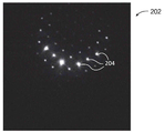
도 1은 회절 스팟(104)으로 구성된 전자 빔 회절 패턴(102)의 예를 나타낸다. 패턴의 대칭은 전자 빔이 결정의 존 축에 평행하다는 것을 의미한다. 빔이 더 이상 존 축에 평행하지 않도록 시료를 기울이면 회절 패턴에 큰 영향이 미친다. 기울어진 시료는 라우에(Laue) 원으로 알려진 원호(arc)로 배열된 일련의 회절 스팟으로 나타나는 패턴을 생성한다. 도 2는 전자 빔에 대하여 기울어진 샘플로부터 획득한, 원호를 형성하는 회절 스팟(204)을 갖는 샘플 회절 패턴(202)을 나타낸다. 회절 패턴으로부터, 전자 빔에 대한 샘플의 존 축의 틸트(tilt)를 결정하는 것이 가능하다. 틸트가 결정되면 샘플이 빔 방향과 정렬되도록 방향을 변경할 수 있다.Fig. 1 shows an example of an electron
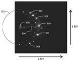
샘플을 빔과 정렬시키기 위해 회절 패턴을 사용하는 하나의 방법은 Jansen et. Al, "Towards automatic alignment of a crystalline sample in an electron microscope along a zone axis", Utramicroscopy 125(2013) 59-65에 의해 기술되었다. 시료의 오정렬(misalignment)의 정도 및 방향은 도 3에 도시된 바와 같이 회절 포인트(304)의 원호에 원(302)을 피팅함으로써 결정된다. 피팅된 원의 중심(308)과 회절 패턴 원호의 전송된 빔 스팟 사이의 반경 벡터(306)의 방향 및 크기는 시료 오정렬의 방향 및 크기에 대응된다. 반경 벡터는 보정 후에 획득된 도 4의 회절 패턴에 의해 지시된 바와 같이, 빔에 평행하게 존 축을 재배향하기 위해 스테이지 틸트로 변환된다. 이 방법은 원하는 정렬이 이루어질 때까지 반복될 수 있다. 샘플이 정렬되면 샘플 상의 대상들을 정확하게 측정할 수 있다.One method of using a diffraction pattern to align the sample with the beam is described in Jansen et. Al, "Towards automatic alignment of a crystalline sample in an electron microscope along a zone axis ", Utramicroscopy 125 (2013) 59-65. The degree and direction of misalignment of the sample is determined by fitting the
이 방법은 경험적 접근(heuristics)을 기반으로 하며 상대적으로 느리다. 일부 회절 패턴에 원을 맞추기가 어렵거나 불가능할 수도 있다. 예를 들어, 도 5에 도시된 바와 같이 원 피팅에 어떤 점을 포함할지를 결정하기가 어려울 수 있다. 빔이 샘플 존 축으로부터 멀리 배향된 샘플로부터 얻어진 도 6에 도시된 이미지에는 많은 스팟이 보이지 않으며, 가시적인 스팟은 전혀 원을 형성하지 않는 것으로 보인다. 또한, 도 6의 패턴은 '2 빔(two beam)' 동적 회절을 겪는 것으로 보인다. 고전 회절 모델은 입자(X-선 또는 전자)가 시료와 상호 작용하는 동안 오직 한 번만 산란한다고 가정한다. 전자는 물질과 강하게 상호 작용하므로, 다중 산란 현상이 발생한다. 빔은 산란하며, 산란된 빔이 다시 산란한다. 이 현상은 동적 회절이라고 한다. 더 두꺼운 재료는 더 많은 산란을 유발한다. 약 20 nm 미만의 두께를 갖는 실리콘의 경우, 동적 회절은 무시될 수 있다. 동적 회절은 라우에(Laue) 원 방법을 실패하게 만들 수 있다. 더욱이, 회절 패턴이 매칭을 위해 충분히 원형이 아니기 때문에, 샘플 오정렬이 1도 미만이면 이 방법은 유용하지 않다. 또한, 원-피팅 루틴(circle-fitting routines)에서 틸트 측정의 정확도를 결정하기가 어려울 수 있다.This method is based on heuristics and is relatively slow. It may be difficult or impossible to match a circle to some diffraction pattern. For example, it may be difficult to determine what points to include in the original fitting as shown in FIG. In the image shown in FIG. 6, where the beam is obtained from a sample oriented away from the sample zone axis, many spots are not visible, and the visible spots appear to not form a circle at all. Also, the pattern of FIG. 6 appears to undergo a " two-beam " dynamic diffraction. The classical diffraction model assumes that particles (X-rays or electrons) only scatter once, while interacting with the sample. The electrons interact strongly with the material, resulting in multiple scattering phenomena. The beam is scattered, and the scattered beam spawls again. This phenomenon is called dynamic diffraction. Thicker material causes more scattering. For silicon with a thickness of less than about 20 nm, dynamic diffraction can be neglected. Dynamic diffraction can cause the Laue circle method to fail. Moreover, since the diffraction pattern is not sufficiently circular for matching, this method is not useful if the sample misalignment is less than one degree. It can also be difficult to determine the accuracy of the tilt measurement in circle-fitting routines.
회절 패턴을 사용하여 존 축 경사를 결정하는 몇 가지 다른 방법이 있다. 예를 들어, 바이스 존 법칙(Weiss zone law)을 사용하면 패턴이 색인되고 두 개-세 개의 두드러진 스팟이 존 축을 찾기 위해 선택된다. 이 방법은 기껏해야 약 2 ~ 3도까지만 정확하며, 이는 결정 정렬에 부적합하다.There are several other ways to determine the zone axis tilt using a diffraction pattern. For example, using the Weiss zone law, the pattern is indexed and two to three prominent spots are selected to find the zone axis. This method is accurate to only about two to three degrees at most, which is unsuitable for crystal alignment.
키쿠치 선(Kikuchi Line)을 사용하는 것은 존 축 틸트를 결정하기 위한 매우 정확하고 표준적인 기술이다. 그것은 수동으로 및/또는 컴퓨터의 도움을 받아 수행될 수 있다. 키쿠치 선은 동적 회절 효과로 인해 생성되며 두께가 두껍거나 높은 Z (원자 번호) 시료에서만 쉽게 볼 수 있다. 그러므로 키쿠치 선 기술은 노드 크기가 현재 10 nm에 근접하고 있는 전자 산업에서 사용되는 샘플과 같이 얇은 샘플에 사용하는 것이 불가능하다.Using the Kikuchi Line is a very accurate and standard technique for determining the zone axis tilt. It can be performed manually and / or with the help of a computer. The Kikuchi line is produced by the dynamic diffraction effect and can be easily seen only in Z (atomic number) samples of thick or high thickness. Thus, Kikuchi wire technology is impossible to use for thinner samples such as those used in the electronics industry, where the node size is now approaching 10 nm.
또 다른 방법은 일련의 회절 패턴을 인덱싱하고 최소 자승법을 사용하여 결정 단위 셀 매개 변수 및 방향을 계산하는 것이다. 이 방법은 두 개 이상의 회절 패턴을 필요로 하며 스테이지를 기울이기 때문에 XYZ에서 변환이 발생한다. 이는 시료가 구겨진 종이처럼 물결 모양이어서 모든 정렬이 국부적이기 때문에 전자 빔 시스템에서 결정 배향을 정렬하기에 매우 적절하지 않다.Another method is to index a series of diffraction patterns and calculate the decision unit cell parameters and directions using a least squares method. This method requires two or more diffraction patterns and tilts the stage so that the transformation occurs in XYZ. This is not very suitable for aligning the crystal orientation in an electron beam system because the sample is wavy like crumpled paper and all alignments are local.
니콜로폴로스 등(Nicolopoulos et al.)의 미국 공개 특허 2011/0220796는 결정 샘플의 전자 회절 단층 촬영을 위한 방법을 기술한다. 다결정 물질은 래스터(raster)로 빔을 스캐닝함으로써 이미징된다. 각각의 빔 위치에서, 회절 패턴은 동적 회절 효과를 억제하기 위해 탑(top)처럼 빔을 처리함으로써 얻어진다. 회절 패턴을 참조 패턴과 비교하여 결정 배향(orientation)을 결정한다. 빔 위치의 함수로서 결정 배향을 나타내는 맵이 생성된다. 물질의 입자는 이러한 텍스처 맵을 검토함으로써 쉽게 볼 수 있다. 배향의 결정은 계측학용 샘플을 정렬하기에 충분히 정확하지 않다. 이 기술은 또한 회절 패턴을 인덱싱하고 문제의 모든 물질에 대해 라이브러리를 유지해야 한다.US Patent Application No. 2011/0220796 to Nicolopoulos et al. Describes a method for electron diffraction tomography of a crystal sample. The polycrystalline material is imaged by scanning the beam with a raster. At each beam position, the diffraction pattern is obtained by processing the beam like a top to suppress the dynamic diffraction effect. The diffraction pattern is compared with the reference pattern to determine the crystal orientation. A map representing the crystal orientation as a function of beam position is generated. Particles of matter can be easily seen by reviewing these texture maps. The orientation determination is not accurate enough to align the instrumental sample. The technique should also index the diffraction pattern and maintain a library of all the materials in question.
본 발명의 목적은 대전된 입자 빔 시스템에서 결정성 샘플을 정렬하기 위한 개선된 방법 및 장치를 제공하는 것이다.It is an object of the present invention to provide an improved method and apparatus for aligning crystalline samples in a charged particle beam system.
대전된 입자 빔은 샘플 회절 패턴을 얻기 위해 샘플을 향한다. 샘플 회절 패턴은 공지된 오정렬을 갖는 참조 회절 패턴과 비교되어 어떤 참조 패턴이 샘플 패턴과 가장 근접한지를 결정한다. 최상의 매칭 참조 회절 패턴의 공지된 정렬은 샘플의 틸트를 보정하는 데 사용된다.The charged particle beam is directed to the sample to obtain a sample diffraction pattern. The sample diffraction pattern is compared to a reference diffraction pattern having a known misalignment to determine which reference pattern is closest to the sample pattern. The best alignment of the best matching reference diffraction pattern is used to correct the tilt of the sample.
전술한 내용은 후술하는 본 발명의 상세한 설명을 보다 잘 이해할 수 있도록 하기 위해 본 발명의 특징 및 기술적 장점을 다소 광범위하게 개략적으로 설명하였다. 본 발명의 추가 특징 및 이점은 이하에서 설명될 것이다. 개시된 개념 및 특정 실시예가 본 발명의 동일한 목적을 수행하기 위한 다른 구조를 변형 또는 설계하기 위한 토대로서 용이하게 이용될 수 있다는 것은 통상이 기술자에게 이해될 것이다. 또한, 통상의 기술자는 이러한 등가 구성이 첨부된 청구 범위에 기재된 본 발명의 범위를 벗어나지 않는다는 것을 이해할 것이다.The foregoing has outlined rather broadly the features and technical advantages of the present invention in order that the detailed description of the invention that follows may be better understood. Additional features and advantages of the invention will be described hereinafter. It will be understood by those skilled in the art that the disclosed concepts and specific embodiments may be readily utilized as a basis for modifying or designing other structures for carrying out the same purpose of the present invention. It will also be appreciated by those of ordinary skill in the art that such equivalent constructions do not depart from the scope of the invention as set forth in the appended claims.
본 발명은 대전된 입자 빔 시스템에서 결정성 샘플을 정렬하기 위한 개선된 방법 및 장치를 제공할 수 있다.The present invention can provide an improved method and apparatus for aligning crystalline samples in a charged particle beam system.
본 발명 및 이의 이점에 대한 보다 완전한 이해를 위해, 첨부된 도면과 관련하여 수행된 이하의 설명을 참조한다.
도 1은 정렬된 시료로부터의 회절 패턴을 나타낸다.
도 2는 오정렬된 시료로부터의 회절 패턴을 나타낸다.
도 3은 오정렬된 샘플로부터의 회절 패턴을 나타낸다.
도 4는 오정렬이 보정된 도 3의 샘플로부터의 회절 패턴을 나타낸다.
도 5는 오정렬을 계산하기 위한 원을 식별하기 어려운 오정렬 샘플의 회절 패턴을 나타낸다.
도 6은 오정렬을 계산하기 위한 원을 식별하기 어려운 오정렬 샘플의 다른 회절 패턴을 나타낸다.
도 7은 회절 패턴을 이용하여 시료를 정렬하는 방법을 나타내는 순서도이다.
도 8은 대응되는 결정면(crystal planes) 그룹으로 식별된 회절 피크를 갖는 오정렬된 샘플의 회절 패턴을 나타낸다.
도 9는 도 8의 샘플의 회절 패턴과 비교하기 위해 사용된 대표적인 참조 회절 패턴을 나타낸다.
도 10은 α 및 β 틸트 축을 따라 각기 다른 각도에서 상관 수준(level of correlation)을 나타내는 휘도를 갖는 도 8의 샘플의 상관 그래프를 나타낸다.
도 11은 샘플 패턴을 참조 패턴과 상관시키는 방법을 나타내는 순서도이다.
도 12는 샘플 패턴을 참조 패턴과 상관시키는 다른 방법을 나타내는 순서도이다.
도 13은 샘플 정렬을 수행하는 데 사용될 수 있는 시스템을 개략적으로 나타낸다.BRIEF DESCRIPTION OF THE DRAWINGS For a more complete understanding of the present invention and the advantages thereof, reference is now made to the following descriptions taken in connection with the accompanying drawings,
Figure 1 shows a diffraction pattern from an aligned sample.
Figure 2 shows the diffraction pattern from the misaligned sample.
Figure 3 shows the diffraction pattern from the misaligned sample.
Figure 4 shows the diffraction pattern from the sample of Figure 3 with misalignment corrected.
FIG. 5 shows a diffraction pattern of a misalignment sample which is difficult to identify a circle for calculating misalignment.
Figure 6 shows another diffraction pattern of a misalignment sample that is difficult to identify a circle for calculating misalignment.
FIG. 7 is a flowchart showing a method of aligning samples using a diffraction pattern. FIG.
Figure 8 shows a diffraction pattern of misaligned samples with diffraction peaks identified as corresponding crystal planes groups.
9 shows an exemplary reference diffraction pattern used for comparison with the diffraction pattern of the sample of Fig.
Fig. 10 shows a correlation graph of the sample of Fig. 8 having a luminance representing a level of correlation at different angles along the alpha and beta tilt axes.
11 is a flowchart showing a method of correlating a sample pattern with a reference pattern.
12 is a flowchart showing another method of correlating a sample pattern with a reference pattern.
Figure 13 schematically shows a system that can be used to perform sample alignment.
대전된 입자 빔은 샘플 회절 패턴을 얻기 위해 샘플을 향한다. 샘플 회절 패턴은 공지된 오정렬을 갖는 참조 회절 패턴과 비교되어 어떤 참조 패턴이 샘플 패턴과 가장 근접한지를 결정한다. 일치하는 참조 회절 패턴의 알려진 틸트는 샘플의 틸트를 보정하는 데 사용된다.The charged particle beam is directed to the sample to obtain a sample diffraction pattern. The sample diffraction pattern is compared to a reference diffraction pattern having a known misalignment to determine which reference pattern is closest to the sample pattern. The known tilt of the matching reference diffraction pattern is used to correct the tilt of the sample.
일부 실시예에서, '참조 패턴'은은 이미지가 전혀 아니며, 스팟들의 리스트이다. 상관(correlation)은 이미지가 아닌 스팟들의 리스트 사이에서 이루어진다. 예를 들어, 스팟들의 리스트에는 다음이 포함될 수 있다.In some embodiments, the ' reference pattern ' is not an image at all, but a list of spots. Correlation is made between lists of spots rather than images. For example, the list of spots may include:
첫 번째 열: 이미지 X 위치First column: Image X position
두 번째 열: 이미지 Y 위치Second column: image Y position
세 번째 열은 다음 중 어느 하나:The third column is one of the following:
밀러(Miller) 색인 (색인 패턴의 경우) Miller index (for index patterns)
산란 각도 (색인되지 않은 패턴의 경우) Scattering angle (for unindexed patterns)
네 번째 열: 스팟 세기Fourth column: Spot intensity
스팟 세기는 스팟 픽셀들을 적분함으로써 결정된다. 두 개의 이미지에서의 픽셀보다 스팟들의 리스트를 상관시키면 계산 상의 부담이 크게 줄어든다. 각각의 이미지에서 백만 픽셀 이상을 고려해야 하는 대신 오직 몇 십 개의 스팟만이 고려된다.The spot intensity is determined by integrating the spot pixels. Correlating the list of spots with respect to the pixels in the two images greatly reduces the computational burden. Instead of considering more than one million pixels in each image, only a few tens of spots are considered.
참조 패턴 '스팟들의 리스트'는 운동학적(kinematical) 모델을 사용하여 즉석에서 계산할 수 있다. 운동학적 모델은 1도, 보다 바람직하게는 1/2도 미만의 존 축 정렬을 제공하기에 충분히 정확하지만, 참조 패턴의 가능한 α 틸트, β 틸트, 샘플 두께, 샘플 유형 등에 대한 라이브러리 유지 없이도 정렬 프로세스 중에 참조 패턴이 계산될 수 있을만큼 충분히 계산적으로 효율적이다.The reference pattern 'list of spots' can be computed on the fly using a kinematical model. The kinematic model is accurate enough to provide zone alignment of less than 1 degree, more preferably less than half a degree, but without the library maintenance of possible alpha tilt, beta tilt, sample thickness, sample type, etc. of the reference pattern, It is computationally efficient enough that the reference pattern can be computed.
실시예들은 정렬을 결정하기 위해 단일 포인트에서 단일 전자 회절 패턴을 사용한다. 실시예들은 포인트 주위에서 전자 빔을 처리하거나 샘플 포인트에 다중 회절 패턴을 취할 필요가 없다. 실시예들은 패턴을 인덱싱할 필요가 없다.Embodiments use a single electron diffraction pattern at a single point to determine alignment. Embodiments do not need to process the electron beam around the point or take multiple diffraction patterns at the sample point. Embodiments do not need to index the pattern.
샘플을 정렬하기 위한 종래 기술의 방법은 샘플 회절 패턴을 분석하여 수학적으로 샘플 틸트를 결정한다. 샘플 회절 패턴을 공지된 틸트를 갖는 회절 패턴과 비교하는 것은 실현 가능성이 없다고 간주되었다. 실현 가능한 회절 시뮬레이션 모델은 실제에 맞게 정렬하기에 충분하지 않다. 참조 패턴은 샘플 물질, 샘플 두께 및 정렬되는 샘플 존 축에 따라 다르다. α 틸트 및 β 틸트의 가능한 조합마다 참조 패턴이 필요하므로 양 축을 따라 샘플 틸트를 정확하게 결정하려면 많은 수의 참조 패턴이 필요하다.Prior art methods for aligning samples analyze the sample diffraction pattern to mathematically determine sample tilt. It has been considered impossible to compare the sample diffraction pattern with the diffraction pattern with known tilt. A feasible diffraction simulation model is not sufficient for real-world alignment. The reference pattern depends on the sample material, the sample thickness, and the sample zone axis to be aligned. Since a reference pattern is required for each possible combination of alpha tilt and beta tilt, a large number of reference patterns are needed to accurately determine the sample tilt along both axes.
예를 들어, 샘플이 두 틸트 축 모두에서 3도의 정렬도 내에 있다고 가정한다면, 0.1도 내에서 틸트를 결정하기를 원할 경우, 3,600 개의 참조 패턴이 필요할 것이다. 3,600 개의 참조 패턴을 생성하고 각각의 참조 패턴을 샘플 회절과 비교하는 것은 실현 가능한 응용에 비하여 계산적으로 너무 과다한(intense) 것으로 간주되어 왔다. 출원인은 시뮬레이션된 회절 패턴을 생성하기 위해 단순화된 모델을 사용하여 샘플을 통해 빔을 통과시킴으로써 검출된 패턴과 비교하여 참조 패턴을 생성할 수 있음을 발견했다.For example, suppose a sample is within 3 degrees of alignment on both tilt axes, and you want to determine the tilt within 0.1 degrees, you would need 3,600 reference patterns. Generating 3,600 reference patterns and comparing each reference pattern with a sample diffraction has been regarded as computationally intense relative to a feasible application. Applicants have discovered that a simplified model can be used to generate a simulated diffraction pattern and generate a reference pattern by passing the beam through the sample in comparison to the detected pattern.
놀랍게도, 출원인은 단순화된 시뮬레이션의 사용이 샘플을 정확히 정렬하기에 충분히 정확한 참조 패턴을 생성한다는 것을 발견했다. 또한, 출원인은 이미지 대신에 스팟들의 리스트를 비교하는 것이 계산의 수를 크게 감소시켜, 몇몇 실시예들에서 비교 방법을 보다 실현 가능하게 한다는 것을 발견하였다.Surprisingly, applicants have found that the use of a simplified simulation produces a reference pattern that is accurate enough to accurately align the sample. Applicants have also found that comparing lists of spots instead of images significantly reduces the number of calculations, making the comparison method more feasible in some embodiments.
도 7은 전자 빔을 사용하여 관측된 샘플과 전자 빔 사이의 오정렬을 측정 및 보정하는 방법을 나타내는 순서도(700)이다. 이 방법은 전형적으로 두께가 250 nm 미만인 얇은 샘플을 말하며, 이를 통해 전자가 전송되고 회절된다. 이러한 방법은 후방 산란 전자 회절 패턴에도 적용될 수 있다. 후방 산란 전자 회절 정렬은 얇은 전자-투명성 샘플에 국한되지 않는다.7 is a
단계 702에서, 얇은 샘플이 전자 빔 시스템의 진공 챔버 내로 로딩된다. 단계 704에서, 평행한 전자 빔이 샘플을 향한다. 샘플은 전자의 대부분이 샘플을 통과할 만큼 충분히 얇다. 단계 706에서, 대물 렌즈의 후 초점면의 이미지는 샘플 아래에 위치된 전자 이미지-형성 (픽셀화된) 검출기 상에 형성되며, 이미지는 컴퓨터 메모리에 저장된다. 후 초점면의 이미지는 전자 회절 패턴에 대응될 것이다. 후방-산란된 전자 회절 패턴은 또한 전자를 후방 산란시키는 더 두꺼운 샘플 위에 배치된 이미지-형성 검출기를 이용하여 획득될 수 있다.At
단계 708에서, 회절 피크에 대응되는 밝은 스팟들이 이미지상에서 식별된다. 밝은 스팟들은 일반적으로 둘 이상의 픽셀로 확장되며, 이미지상의 밝은 픽셀들은 하나의 스팟으로 그룹화된다. 몇몇 실시예에서, 픽셀 그룹의 중심은 스팟의 위치를 식별하도록 결정될 수 있다. 밝은 스팟을 찾기 위해, 이미지의 각 픽셀의 휘도가 정규화될 수 있으며, 각 픽셀의 휘도가 (전자가 충돌하지 않은) 어두운 스팟에 대응되는 "0"과 최대값에 대응되는 "1" 사이의 숫자로 특정된다. 선택적으로, 각 픽셀은 "임계값화(thresholded)"될 수 있다. 즉, 만약 픽셀의 휘도가 특정 값 이상인 경우 픽셀은 "1"의 값이 할당되고 픽셀 휘도가 특정 값보다 작은 경우 "0"의 값이 할당될 수 있다. 밝은 픽셀의 인접한 그룹, 즉 최소값을 초과하는 휘도를 갖는 픽셀은 스팟을 형성하도록 그룹화될 수 있다. 만약 정규화된 휘도가 사용되는 경우, 예를 들어 스팟이 스팟의 최대값의 절반이 되도록 떨어지는 스팟들이 위치하는 픽셀에 의해 스팟들의 가장자리가 결정될 수 있다. 많은 다른 방법들이 회절 스팟을 식별하기 위해 사용될 수 있다.At
회절 패턴에 매우 많은 개수의 피크가 있을 수 있으며, 높은 결정면의 피크는 낮은 인덱스 면의 피크보다 더 어두울 수 있다. 즉, <100> 피크는 일반적으로 <200) 피크 등보다 밝을 수 있다. 단계 708에서, 상관 관계에서 나중에 사용하기 위해 식별된 스팟의 수는 제한될 수 있다. 예를 들어, 스팟 내의 픽셀의 최소 누적(cumulative) 휘도를 갖는 스팟만이 회절 스팟으로 식별될 수 있거나, 특정 수 이하의 결정 인덱스에 대응되는 스팟만이 사용될 수 있다.There may be a very large number of peaks in the diffraction pattern, and the peak of the high crystal face may be darker than the peak of the low index face. That is, the < 100 > peak may generally be brighter than the < 200) peak. In
선택적인 단계 701에서, 단계 708에서 식별된 회절 스팟이 각 스팟에 대응되는 결정면의 세트를 결정하기 위해 인덱싱된다. 도 8은 지수화된 회절 피크를 나타내며, 각각의 피크는 대응되는 결정면으로 라벨링된다. 스팟들은 후속 단계 722에서 상관 관계를 돕기 위해 인덱싱된다. 일부 상관 방법들은 회절 스팟들의 인덱싱을 요구하지 않는다.In optional step 701, the diffraction spot identified in
단계 720에서, 참조 회절 패턴들의 세트는 샘플 회절 패턴과의 비교를 위해 제공된다. 참조 회절 패턴의 세트는 일반적으로 정렬되는 샘플 재료, 두께 및 존 축으로 특정된다. 참조 회절 패턴의 세트는 전자 빔에 대하여 2개의 축을 따라 기울어진 존 축의 범위에 걸친 회절 패턴들을 포함한다.In
도 9는 각각 20 nm 두께의 실리콘에 대한 4개의 대표적인 참조 회절 패턴을 나타내며, 각각은 <110> 방향으로 존 축의 상이한 샘플 틸트에 대응된다. 회절 패턴의 세트는 실험적으로 또는 시뮬레이션 소프트웨어에 의해 생성될 수 있다. 참조 패턴은 이미지일 필요는 없으며, 스팟 리스트 또는 단순히 운동학적 회절 모델일 수 있다. 일반적으로 단백질과 같은 복잡한 결정체에 대한 정확성을 대가로 복잡성 및 계산 비용이 소요되는 회절 패턴 시뮬레이션을 위한 여러 모델이 존재한다. 철저한 시뮬레이션에는 멀티-슬라이스(multi-slice) 시뮬레이션 또는 양자 역학 계산이 포함되며, 이는 계산상 매우 고가이며 표준 구조를 모델링해야 한다.Figure 9 shows four representative reference diffraction patterns for each 20 nm thick silicon, each corresponding to a different sample tilt in the z-axis in the < 110 > direction. The set of diffraction patterns can be generated experimentally or by simulation software. The reference pattern need not be an image, but may be a spot list or simply a kinematic diffraction model. In general, there are several models for simulating diffraction patterns that require complexity and computational cost in exchange for the accuracy of complex crystals such as proteins. A thorough simulation involves multi-slice simulation or quantum mechanics calculations, which are computationally expensive and must model the standard structure.
예를 들어, 빔 축(Z-축)에 대하여 수직 입사각으로부터 -3도 내지 +3도 기울어진 회절 패턴이 α 및 β 축 모두에 대해 시뮬레이션될 수 있다. 샘플링 분해능과 시뮬레이션된 오정렬의 정도는 시뮬레이션 및 이후 비교를 위해 증가된 계산 시간과의 균형에 따라 예상되는 최대 정렬 오정렬과 요구되는 정밀도를 기초로 선택될 수 있다. 예를 들어, α 및 β 축 모두에서, 샘플 틸트가 있는 참조 패턴은 빔 축에 대한 수직 입사각에 대하여 -10도에서 +10도, 수직 입사각에 대하여 -5도에서 +5도, 또는 -2도에서 +2도까지의 틸트 범위에서 사용할 수 있다. 가능한 참조 패턴 해상도는 1도, 0.1도, 0.05도, 또는 0.01도를 포함한다. 다른 틸트 각도 범위와 해상도가 사용될 수도 있다. 정렬 프로세스는 반복적으로 수행될 수 있는데, 더 넓은 범위의 틸트에 대해 낮은 해상도로 대략적인 정렬을 수행한 후 더 작은 범위의 틸트에 대해 보다 정밀하게 최종 정렬을 달성할 수 있다. 그러나, 샘플을 기울이면 일반적으로 빔에 대하여 샘플의 일부 측면 이동이 일어나 관심 영역이 시야 밖으로 이동될 수 있기 때문에 단일 보정을 사용하는 것이 바람직하다. 이러한 움직임을 보완하기 위해 정교하고 시간 소모적인 특징 추적 절차가 실행되어야 한다. 또한, 스테이지의 기계적 정확도가 해상도를 제한한다.For example, a diffraction pattern can be simulated for both the [alpha] and [beta] axes that is inclined by -3 to +3 degrees from the normal incidence angle with respect to the beam axis (Z-axis). The sampling resolution and the degree of simulated misalignment can be selected based on the expected maximum alignment alignment and the required accuracy, balanced with the simulation time and the increased computation time for later comparisons. For example, in both the? And? Axes, the reference pattern with sample tilt has a magnitude of -10 degrees to +10 degrees with respect to the normal incidence angle with respect to the beam axis, +5 degrees with respect to the normal incidence angle, To +2 degrees of tilt. Possible reference pattern resolutions include 1 degree, 0.1 degree, 0.05 degree, or 0.01 degree. Other tilt angle ranges and resolutions may be used. The alignment process can be performed iteratively, so that the final alignment can be achieved more precisely for a smaller range of tilt after performing coarse alignment with a lower resolution for a wider range of tilts. However, it is desirable to use a single calibration because tilting the sample generally results in some lateral movement of the sample with respect to the beam and the region of interest may be moved out of sight. In order to compensate for this movement, a sophisticated and time-consuming feature tracking procedure must be implemented. Also, the mechanical accuracy of the stage limits the resolution.
시뮬레이션된 참조 패턴은 사용을 위해 미리 생성되고 검색되거나, 정렬 프로세스 중에 요구될 때 시뮬레이션된 패턴이 생성될 수 있다. 요구되는 계산을 감소시키기 위해, 참조 회절 패턴을 생성하는 데 사용된 회절 시뮬레이션은 동적 회절로부터의 기여를 무시하고 운동학적 회절 모델을 기반으로 수행될 수 있다. 운동학적 회절 모델은 대전된 입자가 샘플을 통과할 때의 거동을 가정한다. 예를 들어, 입사 광선은 전체 샘플에 걸쳐 균질한 것으로 간주되며, 비탄성 산란은 무시되며 회절된 빔의 2차 회절도 무시된다. 일부 실시예에서, 시뮬레이션된 회절 패턴을 계산하는 단순하고 계산 상 효율적인 수단은 결정 배향에 의해 결정되는 Z 축 여기 인자 영향을 줌인(zoom in)하기 위해 산란 각도의 함수로서 통합된 회절 피크를 가중(upweighting)하는 것을 포함한다. 스팟 세기를 관리하는 데는 여러 가지 요인이 있지만, 우리는 정렬을 위해 결정 정렬이 스팟 세기에 어떻게 영향을 미치는지에만 관심이 있다. 시뮬레이션의 목표는 다른 모든 효과를 억제하고 이러한 효과는 확대하는 것이다. 관심의 영향은 여기 요인(excitation factors)이라고 한다. 이러한 회절 시뮬레이션 전략은 광범위한 회절 시뮬레이션의 계산 비용을 크게 줄인다. 본 출원인은 놀랍게도, 동적 회절을 배제하는 것이 얇은 샘플에 대한 샘플 틸트의 결정 및 보정의 정확도에 영향을 미치지 않으면서 시뮬레이션의 속도를 향상시킨다는 것을 발견했다. 면심 입방형(face-centered-cubic) 결정과 같이 높은 대칭성을 갖는 결정의 경우, 시뮬레이션된 회절 패턴은 다른 틸트에 대응되는 패턴의 "온 더 플라이(on the fly)" 생성이 용이하도록 상대적으로 빠르게 생성될 수 있다.The simulated reference pattern may be generated and retrieved for use in advance, or a simulated pattern may be generated when required during the alignment process. To reduce the required calculations, the diffraction simulation used to generate the reference diffraction pattern can be performed based on a kinematic diffraction model, ignoring the contribution from the dynamic diffraction. Kinematic diffraction models assume the behavior of charged particles as they pass through the sample. For example, incident light is considered homogeneous throughout the sample, inelastic scattering is ignored and the second order diffraction of the diffracted beam is also ignored. In some embodiments, a simple and computationally efficient means of calculating the simulated diffraction pattern is to weight the integrated diffraction peak as a function of the scattering angle to zoom in on the Z-axis excitation factor influence determined by the crystal orientation upweighting. There are many factors in managing spot intensity, but we are only interested in how crystal alignment affects spot intensity for alignment. The goal of the simulation is to suppress all other effects and enlarge those effects. The influence of interest is called excitation factors. This diffraction simulation strategy greatly reduces the computational cost of extensive diffraction simulations. The Applicant has surprisingly found that excluding the dynamic diffraction improves the speed of the simulation without affecting the accuracy of the determination and correction of the sample tilt for thin samples. For crystals with high symmetry, such as face-centered-cubic crystals, the simulated diffraction pattern is relatively fast to facilitate "on the fly" generation of patterns corresponding to other tilts Lt; / RTI >
다른 예로서, 기준 회절 패턴은 존 축에 대하여 공지된 틸트를 갖는 샘플로부터의 샘플 회절 패턴일 수 있다. 예를 들어, 샘플은 종래의 방법을 사용하여 정렬될 수 있고, 그 다음 공지된 양만큼 기울어져 다양한 공지된 틸트에서 기준 회절 패턴을 생성할 수 있다. 다른 샘플이 다른 유형의 샘플 물질, 다른 샘플 두께, 및 다른 존 축을 위해 요구될 수 있다. 각각의 스팟에 대응되는 각 픽셀의 세기는 각각의 스팟의 세기를 결정하기 위해 적분된(integrated)다. "세기"는 충돌하는 전자의 수에 해당하며 이는 전자 회절 이미지의 휘도에 해당한다. "세기"는 실제로 이미지를 생성하지 않고 시뮬레이션에서 결정될 수 있다. 이 경우, 기준 회절 패턴은 스팟이 특정 결정면(crystal planes) 세트로 식별되도록 인덱싱되어야 한다.As another example, the reference diffraction pattern may be a sample diffraction pattern from a sample having a known tilt with respect to the zone axis. For example, the sample may be aligned using conventional methods, and then tilted by a known amount to produce a reference diffraction pattern at various known tilts. Other samples may be required for different types of sample material, different sample thicknesses, and different zone axes. The intensity of each pixel corresponding to each spot is integrated to determine the intensity of each spot. "Strength" corresponds to the number of colliding electrons, which corresponds to the luminance of the electron diffraction image. "Strength" can be determined in the simulation without actually producing an image. In this case, the reference diffraction pattern should be indexed such that the spot is identified as a particular set of crystal planes.
각각의 기준 패턴은 인덱싱된 피크의 테이블 및/또는 피크 세기의 테이블을 포함한다. 이들 테이블은 기준 패턴을 샘플 패턴과 상관시키기 위해 사용될 수 있다. 테이블은 이미지 대신에 회절 패턴을 상관시키기 위해 사용되기 때문에, 계산하기에 실현 가능하지 않은 상이한 이미지를 정렬하고 스케일링하는 과정을 수행할 필요가 없다.Each reference pattern includes a table of indexed peaks and / or a table of peak intensities. These tables can be used to correlate the reference pattern with the sample pattern. Since the table is used to correlate diffraction patterns instead of images, there is no need to perform a process of aligning and scaling different images that are not feasible to calculate.
다음으로, 샘플 패턴 상의 회절 피크의 세기는 단계 722에서 기준 패턴 중 하나에 대응하는 피크의 세기 또는 운동학적 회절 모델로부터의 세기와 상관되어, 그 기준 패턴에 대한 상관 점수(correlation score)를 결정한다. 피크의 세기를 상관하는 여러 방법이 있으며, 이하에서는 도 11 및 도 12를 참조하여 2개의 방법에 대하여 설명한다. 단계 722는 결정 블록(724, decision block)이 모든 기준 패턴이 샘플 패턴과 상관되었다고 결정할 때까지 반복된다. 예를 들어, 0.1도 단위로 α 및 β 틸트에서 -10도 내지 +10도 사이에서, 하나도 빠짐없이 참조 격자 세트가 생성되는 경우, 단계 722가 40,000번 반복된다. 대안적으로, 프로세스는 기준 패턴이 사전에 규정된 높은 상관 점수를 갖는 경우에 중단될 수 있다.Next, the intensity of the diffraction peak on the sample pattern is correlated with the intensity of the peak corresponding to one of the reference patterns or the intensity from the kinematic diffraction model in
도 10은 x-축이 β 틸트 및 y-축이 α 틸트를 갖는 상관 그래프를 나타낸다. 상관 그래프에서 더 밝은 스팟일수록, 해당 β 틸트 및 α 틸트에서 샘플 회절 패턴과 시뮬레이션 패턴 사이의 상관 점수가 높아진다. 상관 관계 그래프는 -3도 내지 +3도의 α 틸트와 -3도 내지 +3도의 β 틸트의 3,600 가지 조합을 모두 α 틸트와 β 틸트에서 0.1도씩 증가시켜 모델링함으로써 구성된다. 도 10은 약 0도의 α 틸트와 약 2도의 β 틸트에서 가장 높은 상관 포인트(1002)를 나타낸다.FIG. 10 shows a correlation graph in which the x-axis has? Tilt and the y-axis has? Tilt. The brighter the spot in the correlation graph, the higher the correlation score between the sample diffraction pattern and the simulation pattern at the corresponding? -Tilt and? -Tilt. The correlation graph is constructed by modeling 3,600 combinations of alpha tilt of -3 degrees to +3 degrees and beta tilt of -3 degrees to +3 degrees by 0.1 degree increments in alpha tilt and beta tilt, respectively. Fig. 10 shows the
가장 잘 일치하는 기준 패턴의 공지된 존 축 틸트는 샘플의 실제 존 축 틸트인 것으로 추정된다. 결정 블록(726)은 샘플 존 축 틸트가 사전에 규정된 최소값, 예컨대 1.0도 미만 또는 0.5도 미만보다 작은지를 결정한다. 만약 결정 블록(726)이 존 축 틸트가 사전에 규정된 최소값보다 작지 않다고 결정하면, 단계 728에서 결정된 존 축 틸트를 보정하도록 빔과 샘플 표면 사이의 각도가 변경된다. 샘플 스테이지는 전자 빔에 존 축을 정렬하기 위해 물리적으로 기울어질 수 있다. 스테이지를 기울이면 표본에서 XYZ 변환이 유도되어 관심 영역이 시야 밖으로 이동하게 되므로 스테이지 틸트 수를 제한하는 것이 바람직하다. 정교하고 시간 소모적인 특징 추적 과정을 보상하는 것을 반드시 수행되어야 한다. 본 발명은 오직 하나의 스테이지 틸트만을 사용하여 결정이 최적의 배향으로 기울어지게 할 수 있다.The known zone axis tilt of the best matching reference pattern is assumed to be the actual zone axis tilt of the sample.
단계 722에서 샘플 회절 패턴 및 기준 회절 패턴에 대한 피크의 위치를 상관시키는 하나의 방법은 샘플 패턴 및 기준 패턴의 회절 피크에 대응하는 픽셀의 휘도를 단순히 곱하는 것이다. 만약 그것이 회절 피크의 일부를 나타낸다면 샘플 회절 패턴에서 픽셀의 휘도는 0이 아니다. 기준 회절 패턴에서 대응하는 픽셀에 회절 피크가 없다면, 기준 패턴에서 대응하는 픽셀의 휘도 값은 0 또는 0에 가깝게 될 것이다. 기준 패턴에 피크가 있는 경우 기준 패턴의 휘도 값은 1에 가깝고, 획득된 패턴 및 기준 패턴의 휘도의 곱은 1에 가까울 것이다.One way of correlating the positions of the peaks with respect to the sample diffraction pattern and the reference diffraction pattern in
도 11은 도 7의 단계 722에서 요구되는 샘플 회절 패턴과 기준 패턴 사이의 상관 점수를 결정하는 방법을 설명하는 순서도(1100)이다. 샘플 회절 패턴에서 단계 708에서 식별된 밝은 스팟은 단계 710에서 인덱싱된다. 단계 1104에서 인덱싱된 피크 각각의 세기가 결정되고 기록된다. 샘플 이미지를 피크 리스트로 감소시키고 오직 피크만을 비교함으로써, 이미지의 픽셀(1,000 x 1,000 픽셀 이미지는 1,000,000 픽셀을 갖는다)을 비교하는 대신 처리할 정보량이 10,000보다 큰 인자(factor)만큼 감소된다.11 is a
단계 1106에서 기준 회절 패턴 상의 밝은 스팟들이 인덱싱되고, 단계 1108에서 인덱싱된 피크들 각각의 세기가 결정되고 기록된다. 또한, 단계들 1106 및 1008은 기준 세트가 생성될 때 수행될 수 있다. 상술한 바와 같이, 기준 세트는 정렬 프로세스 전에 생성되거나 정렬 프로세스 중에 필요에 따라 생성될 수 있다. 단계 1110에서, 샘플 회절 패턴 및 기준 회절 패턴 상의 대응되는 피크의 세기가 피크 상관 점수를 결정하기 위해 비교된다. 고려 중인 모든 피크가 결정 블록(1112)에 도시된 바와 같이 상관될 때까지 개별적인 피크가 상관되고, 패턴 상관 점수는 단계 1114에서, 예를 들어 피크 상관 점수의 가중 평균을 합산하거나 수행(summing or performing)함으로써 결정된다. 상관 후에, 정렬 프로세스는 도 7의 단계 724에서 계속된다.In
도 12는 도 7의 단계 722에 대한 '기준 패턴'과 샘플 회절 패턴을 상관시키는 다른 방법을 나타내는 순서도(1200)이다. 도 12의 방법에서, 추정 세기를 계산하는 데에 인덱싱을 사용할 수는 있지만, 필요하지 않은 피크를 인덱싱한다. 단계 1202에서, 스팟들의 리스트를 생성하기 위해 각각의 샘플 스팟의 세기가 결정되고 기록된다. 이미지를 스팟 리스트로 감소시키고 오직 스팟을 비교함으로써, 이미지의 픽셀을 비교하는 것에 비해 처리해야 할 정보의 양이 10,000보다 큰 인자만큼 감소된다. FIG. 12 is a
단계 1204에서, 각 스팟의 세기는 운동학적(kinematical) 회절 모델을 사용하여 추정된다. 스팟 추정 세기는 α 틸트 및 β 틸트, 샘플 재료 유형 및 두께와 같은 모델 입력 매개 변수에 따라 달라진다. 목적은 관찰된 데이터와 가장 잘 일치하는 모델 매개 변수 세트를 찾는 것이다. 운동학적 모델의 경우, 스팟 산란 각도만이 예상 세기를 계산하는 데 필요하다. 따라서, 인덱싱이 필요하지 않다. In
산란 각도는 캘리브레이션된(calibrated) 카메라 길이를 갖는 회절 패턴으로부터 얻어질 수 있다 운동학적 모델은 다음과 같다. 관찰된 회절 패턴은 평면에 수직으로 정렬된 재배열을 가진 역 격자의 평면으로 작용하며, 모델은 에발트 구면(Ewald sphere)으로 구성된다. 추정 세기는 Wiiliam, et al., Transmission Electro Microscopy A Textbook for Materials Science, Springer, (1996) (pp. 197-366) ("Wiiliams, et al.") 17.1A에 기술된 바와 같이 에발트 구면이 랠로드(relrods)를 어떻게 잘랐는지에 기초하여 계산된다. 에발트 구면 배향은 α 및 β를 기반으로 한다. 랠로드(relrod) 크기는 표본 두께를 기반으로 한다. 또한, 추정된 세기는 크로머-만(Kromer-Mann) 방법을 사용하여 추정된 원자 산란 인자 및 데바이-월러 열 B 인자(Debye-Waller thermal B factor)에 의해 측정된다. 스팟의 세기를 결정하기 위한 방법은, 예를 들어, B. Rupp, biomolecular Crystallography Principles, Practive, and Application to Structural Biology, Garland Science (2009) (pp. 197-313) 및 Wiiliams, et al에 기술되어 있다. 도 6의 회절 패턴과 같은 일부 회절 패턴은 인덱싱하기가 매우 어렵기 때문에 회절 패턴을 인덱싱할 필요가 없다는 것은 도 12에 설명된 방법의 이점이다. 단계 1206에서, 첫 번째 스팟이 선택된다.The scattering angle can be obtained from a diffraction pattern with a calibrated camera length. The observed diffraction pattern acts as the plane of the reciprocal lattice with the rearrangement aligned perpendicular to the plane, and the model consists of the Ewald sphere. As described in 17.1A, Ebert's spherical surface is the most widely used surface model, as described in Wiiliam, et al., Transmission Electro Microscopy A Textbook for Materials Science, Springer, (1996) (pp. 197-366) It is calculated based on how the rel rods were cut. The Baltic sphere orientation is based on α and β. The rellord size is based on the sample thickness. In addition, the estimated intensity is measured by an estimated atomic scatter factor and a Debye-Waller thermal B factor using the Kromer-Mann method. Methods for determining the intensity of a spot are described, for example, in B. Rupp, Biomolecular Crystallography Principles, Practive, and Application to Structural Biology, Garland Science (2009) (pp. 197-313) and Wiiliams, et al have. It is an advantage of the method described in FIG. 12 that some diffraction patterns, such as the diffraction pattern of FIG. 6, are very difficult to index and therefore do not need to index the diffraction pattern. In
단계 1208에서, 샘플 회절 패턴 상의 선택된 스팟의 적분된 세기는 모델 입력 파라미터의 함수로서 추정된 스팟 세기와 곱해진다. 여기서, 우리는 도 11에서와 같이 기준 회절 패턴을 매칭하기보다는 데이터에 운동학적 회절 모델을 맞추고 있다. 이는 도 11 및 도 12의 방법들 사이의 차이점이다. 도 12의 방법에서, 관찰된 패턴에서 스팟에 대해 단지 계산된 추정 세기에 대응하는 스팟은 존재하지 않는다. 추정된 세기는 바람직하게 1) 산란 각도 2) 모델 파라미터를 기반으로 하는 것이 바람직하다. 이러한 프로세스는 상관 관계에서 사용되는 모든 스팟에 대해 반복된다. 결정 블록(1210)에서 모든 스팟이 상관되어 있다고 결정되면, 예를 들어 각 스팟에 대한 상관 점수들의 합에 대응되는 상관 점수가 단계 1212에서 결정된다. 예를 들어, 패턴 상관 점수는 각 스팟의 상관 점수의 합이거나, 스팟 상관 점수의 가중 합계(weighted sum)일 수 있다. 최소 휘도 이하의 회절 피크는 제외될 수 있다. 상관(correlation) 후, 정렬 프로세스는 도 7의 단계 724를 계속한다.In
도 13은 여기서 기술된 방법을 사용하여 회절 패턴이 획득될 수 있고 샘플이 정렬될 수 있는 대전된 입자 장치의 개략도를 나타낸다. 전자총(1302)은 빔 축(1306)을 정의하는 전자 빔(1304)을 생성한다. 전자 빔(1308)은 집광 렌즈(1308, 1310)에 의해 포커싱 및 콜리메이팅된다. 집광 조리개(1312)는 빔 전류를 제한하고, 필요에 따라 빔을 성형하는 데 사용될 수 있다. 회절 모드에서, 빔을 구성하는 전자의 궤적은 집광 렌즈 및 조리개를 통과한 후에 평행하다. 얇은 표본(1316)은 샘플 홀더(1328)의 팁(tip) 내에 위치된다. 샘플 홀더는 전자 빔으로 조사될 수 있는 위치(1314)에 있도록 샘플 입자가 대전된 입자 장치에 삽입된다. 일부 실시예에서, 샘플 홀더는 빔 축(1306)에 대해 샘플을 기울이도록 구성된다. 샘플 홀더를 기울이는 것은 자동, 수동, 또는 수동 개시 후 자동으로 수행될 수 있다. 다른 실시예에서, 샘플과 빔 축 사이의 틸트는 조사 위치(1314) 위아래(명확성을 위해 도시하진 않음)의 편향 코일을 사용하여 달성된다.13 shows a schematic view of a charged particle device in which a diffraction pattern can be obtained using the method described herein and in which the sample can be aligned. The
샘플을 통과한 후에, 전자는 대물 렌즈(1318)에 의해 포커싱된다. 도 13에 도시된 렌즈를 이용하여, 회절 패턴이 대물 렌즈(1318)의 후방 초점면(1320)에 형성된다. 투사 렌즈(1322, 1324)는 회절 패턴을 검출기(1326)에 포커싱시킨다. 검출기(1326)는 이미지 형성 검출기이며, 이러한 검출기는 일반적으로 이미지의 각 점 또는 픽셀의 휘도가 검출기의 해당 픽셀에 충돌하는 전자의 수에 대응되는 각각의 검출 셀 또는 픽셀의 어레이를 포함한다. 검출기(1326)는 씨모스 활성 픽셀 센서(CMOS Active Pixel Sensor), 신틸레이터-씨씨디(scintillator-CCD) 검출기 또는 광 민감성 카메라 상에 이미징된 형광 스크린과 같은 공지된 픽셀화된 TEM 검출기일 수 있다.After passing through the sample, the electrons are focused by the
렌즈, 검출기, 샘플 홀더, 및 전자총은 제어기(1330)와 통신하며 제어기(1330)에 의해 제어될 수 있다. 제어기는 비휘발성 메모리(1332)에 저장된 명령 및 다른 데이터를 검색하고 디스플레이(1334) 상에 정보를 표시할 수 있다. 메모리(1332)는 도 7, 도 11 내지 도 13의 프로세스를 포함하며, 본 명세서에서 설명된 프로세스를 수행하기 위한 컴퓨터 명령어를 포함할 수 있다. 본 명세서에서 설명한 방법은 부분적으로 또는 완전히 자동화될 수 있고 제어기(1330)의 제어 하에 작동될 수 있다. 그 다음, 제어기(1330)는 메모리(1332)의 명령에 따라 본 명세서에서 설명된 방법을 수행하기 위해 대전된 입자 빔을 제어할 수 있다.The lens, detector, sample holder, and electron gun are in communication with the
전자 빔 시스템이 참조적으로 제시되었지만, 본 명세서에서 기술된 방법 및 장치는 전자에 한정되지 않으며 다른 유형의 대전된 입자가 사용될 수도 있다.Although electron beam systems are presented by way of reference, the methods and apparatus described herein are not limited to electrons and other types of charged particles may be used.
본 발명의 몇몇 실시예는 대전된 입자 빔 축과 결정성(crystalline) 샘플의 존 축(zone axis) 사이의 배향 오정렬 보정 방법을 제공하며, 상기 방법은, 상기 대전된 입자 빔을 상기 결정성 샘플에 조사하는 단계; 다수의 샘플 회절 스팟들로 구성된 상기 대전된 입자 회절 패턴인 샘플 회절 패턴을 기록하는 단계; 상기 샘플 회절 패턴에서의 상기 회절 스팟들의 세기를, 각각이 상기 대전된 입자 빔 축과 결정의 상기 존 축 사이의 공지된 오정렬에 대응되는 다수의 참조 회절 패턴들의 대응되는 회절 스팟들의 세기와 상관시키는 단계; 및 상기 샘플 회절 패턴과 가장 근접한 상관(correlation)을 갖는 상기 참조 회절 패턴의 공지된 오정렬을 이용하여 상기 샘플 배향을 조정하는 단계를 포함한다.Some embodiments of the present invention provide a method of correcting an alignment misalignment between a charged particle beam axis and a zone axis of a crystalline sample, the method comprising: applying the charged particle beam to the crystalline sample ; Recording a sample diffraction pattern that is the charged particle diffraction pattern composed of a plurality of sample diffraction spots; Correlating the intensity of the diffraction spots in the sample diffraction pattern with the intensity of corresponding diffraction spots of a plurality of reference diffraction patterns each corresponding to a known misalignment between the charged particle beam axis and the zone axis of the crystal step; And adjusting the sample orientation using a known misalignment of the reference diffraction pattern having a correlation closest to the sample diffraction pattern.
몇몇 실시예에서, 상기 다수의 참조 회절 패턴들은 컴퓨터 시뮬레이션을 이용하여 생성된다.In some embodiments, the plurality of reference diffraction patterns are generated using computer simulation.
몇몇 실시예에서, 상기 다수의 참조 회절 패턴들 각각은 스팟들의 리스트를 포함하며, 상기 샘플 회절 패턴의 상기 회절 스팟들의 세기를 상기 다수의 참조 회절 패턴들의 대응되는 회절 스팟들의 세기와 상관시키는 단계는, 상기 샘플 회절 스팟들의 리스트의 세기를 스팟들의 참조 리스트들과 상관시키는 단계를 포함한다.In some embodiments, each of the plurality of reference diffraction patterns includes a list of spots, and the step of correlating the intensity of the diffraction spots of the sample diffraction pattern with the intensity of corresponding diffraction spots of the plurality of reference diffraction patterns And correlating the intensity of the list of sample diffraction spots with the reference lists of spots.
몇몇 실시예에서, 상기 샘플 회절 스팟들의 리스트의 세기를 스팟들의 참조 리스트들과 상관시키는 단계는 밀러(Miller) 인덱스들을 사용하여 샘플 회절 스팟들의 리스트 내의 스팟들을 상기 스팟들의 참조 리스트들 내의 스팟들과 매칭하는 것을 포함할 수 있다.In some embodiments, correlating the intensity of the list of sample diffraction spots with the reference lists of spots may include using spots in the list of sample diffraction spots with spots in the reference lists of the spots using Miller indices, Matching < / RTI >
몇몇 실시예에서, 상기 샘플 회절 스팟들의 리스트의 세기를 스팟들의 참조 리스트들과 상관시키는 단계는 샘플 회절 스팟들의 리스트 내의 스팟들을 상기 스팟들의 참조 리스트들 내의 스팟들과 매칭하기 위해 산란 각도들(scattering angles)을 사용하는 것을 포함한다.In some embodiments, the step of correlating the intensity of the list of sample diffraction spots with the reference lists of spots may include scattering of the spots in the list of sample diffraction spots with spots in the reference lists of the spots. angles.
몇몇 실시예에서, 상기 다수의 참조 회절 패턴들에 대한 상기 스팟들의 리스트는 운동학적 산란 모델(kinematic scattering model)을 사용하여 생성된다.In some embodiments, the list of spots for the plurality of reference diffraction patterns is generated using a kinematic scattering model.
몇몇 실시예에서, 컴퓨터 시뮬레이션을 사용하여 상기 다수의 기준 회절 패턴들을 생성하는 단계는 동적 산란으로부터의 기여(contribution)를 배제하는 산란 모델을 사용하는 단계를 포함한다.In some embodiments, generating the plurality of reference diffraction patterns using computer simulation includes using a scattering model that excludes contributions from dynamic scattering.
몇몇 실시예에서, 상기 기준 회절 패턴들 상의 상기 스팟들의 상기 세기들은 상기 기준 회절 패턴들을 인덱싱하지 않고 결정된다.In some embodiments, the intensities of the spots on the reference diffraction patterns are determined without indexing the reference diffraction patterns.
몇몇 실시예에서, 상기 기준 회절 패턴들 상의 상기 스팟들의 상기 세기들은 상기 기준 회절 패턴들을 캘리브레이션함으로써 결정된다.In some embodiments, the intensities of the spots on the reference diffraction patterns are determined by calibrating the reference diffraction patterns.
몇몇 실시예에서, 컴퓨터 시뮬레이션을 사용하여 상기 다수의 기준 회절 패턴들을 생성하는 단계는 Z 축 여기 인자 효과들을 줌인(zoom in)하기 위해 상기 적분된 회절 피크들을 가중(upweighting)하는 단계를 포함한다.In some embodiments, generating the plurality of reference diffraction patterns using computer simulation includes weighting the integrated diffraction peaks to zoom in for Z-axis excitation factor effects.
몇몇 실시예에서, 상기 대전된 입자를 결정성 샘플에 조사하는 단계는 면심 입방(face-centered cubic) 결정 구조를 갖는 샘플을 조사하는 단계를 포함한다.In some embodiments, the step of irradiating the charged particles to a crystalline sample comprises irradiating a sample having a face-centered cubic crystal structure.
몇몇 실시예에서, 상기 다수의 기준 회절 패턴들은 2차원의 샘플 틸트들을 나타내는 틸트 시리즈를 포함한다.In some embodiments, the plurality of reference diffraction patterns include a tilt series that represents two-dimensional sample tilts.
본 발명의 몇몇 실시예는 대전된 입자 빔 축과 결정성(crystalline) 샘플의 존 축(zone axis) 사이의 배향 오정렬 보정 방법을 제공하며, 상기 방법은, 상기 대전된 입자 빔을 상기 결정성 샘플에 조사하는 단계; 대전된 입자 회절 패턴을 기록하는 단계; 상기 샘플 회절 패턴을, 각각이 대전된 입자 빔 축과 결정의 존 축 사이의 공지된 오정렬에 대응되는 다수의 참조 회절 패턴들과 상관시키는(correlating) 단계; 및 상기 샘플 회절 패턴과 가장 근접한 상관을 갖는 상기 참조 회절의 상기 공지된 오정렬을 사용하여 상기 샘플 배향을 조정하는 단계를 포함한다.Some embodiments of the present invention provide a method of correcting an alignment misalignment between a charged particle beam axis and a zone axis of a crystalline sample, the method comprising: applying the charged particle beam to the crystalline sample ; Recording a charged particle diffraction pattern; Correlating the sample diffraction pattern with a plurality of reference diffraction patterns each corresponding to a known misalignment between the charged particle beam axis and a zone axis of the crystal; And adjusting the sample orientation using the known misalignment of the reference diffraction with the closest correlation to the sample diffraction pattern.
몇몇 실시예에서, 상기 다수의 참조 회절 패턴들은 2개의 직교하는 회전축을 따라 오정렬들에 대응된다.In some embodiments, the plurality of reference diffraction patterns correspond to misalignments along two orthogonal axes of rotation.
몇몇 실시예에서, 상기 산란 모델은 동적 산란으로부터의 기여(contribution)을 배제한다.In some embodiments, the scattering model excludes a contribution from dynamic scattering.
몇몇 실시예에서, 상기 샘플 회절 패턴을 다수의 참조 회절 패턴들과 상관시키는 단계는 대응되는 회절 피크의 상기 세기를 상관시키는 단계를 포함한다.In some embodiments, correlating the sample diffraction pattern with a plurality of reference diffraction patterns comprises correlating the intensity of a corresponding diffraction peak.
몇몇 실시예에서, 상기 샘플 회절 패턴을 다수의 참조 회절 패턴들과 상관시키는 단계는 상기 샘플 회절 패턴의 픽셀들의 휘도(brightness)를 상기 기준 회절 패턴의 픽셀들의 휘도와 상관시키는 단계를 포함한다.In some embodiments, correlating the sample diffraction pattern with a plurality of reference diffraction patterns comprises correlating the brightness of the pixels of the sample diffraction pattern with the brightness of pixels of the reference diffraction pattern.
몇몇 실시예에서, 상기 샘플 회절 패턴 또는 상기 기준 회절 패턴 중 어느 하나에서 0이 아닌 휘도를 갖는 픽셀들만 상관시키는 단계는 상기 회절이 상기 샘플 회절 패턴의 밝은 픽셀들을 상기 샘플 회절 패턴의 대응 위치들과 상관시키는 것을 포함하며, 인덱스보다 물리적인 위치에 기초하여 상관되는 픽셀들에 무관하게 샘플 회절 패턴의 대응되는 위치와 샘플 회절 패턴의 밝은 픽셀들을 상관시키는 단계를 포함한다.In some embodiments, correlating only the pixels having a non-zero brightness in either the sample diffraction pattern or the reference diffraction pattern may be performed such that the diffraction differs bright pixels of the sample diffraction pattern from corresponding positions of the sample diffraction pattern And correlating bright pixels of the sample diffraction pattern with corresponding positions of the sample diffraction pattern irrespective of the pixels correlated based on the physical location than the index.
몇몇 실시예는 대전된 입자 빔 장치를 제공하며, 대전된 입자 빔 장치는 대전된 입자들의 소스; 대전된 입자들의 평행한 빔을 형성하기 위한 대전된 입자 광학 컬럼(optical column); 및 상기 결정성 샘플에 상기 대전된 입자 빔을 조사하는 단계; 대전된 입자 회절 패턴을 기록하는 단계; 및 상기 샘플 존 축(zone axis)과 상기 빔 사이의 오정렬을 결정하기 위해, 상기 샘플 회절 패턴을, 각각이 대전된 입자 빔 축과 결정의 존 축 사이의 공지된 오정렬에 대응되는 다수의 참조 회절 패턴들과 상관시키는 단계를 위한 컴퓨터 명령들을 저장하는 메모리를 포함하는 제어기;를 포함한다.Some embodiments provide a charged particle beam device, wherein the charged particle beam device comprises a source of charged particles; A charged particle optical column for forming a parallel beam of charged particles; And irradiating the crystalline sample with the charged particle beam; Recording a charged particle diffraction pattern; And comparing the sample diffraction pattern with a plurality of reference diffraction orders, each corresponding to a known misalignment between the charged particle beam axis and the zone axis of the crystal, to determine misalignment between the sample zone axis and the beam. And a controller that includes a memory for storing computer instructions for correlating the patterns.
몇몇 실시예에서, 상기 대전된 입자 빔 장치는 상기 샘플 회절 패턴에 가장 근접하게 상관된 상기 참조 회절의 공지된 오정렬을 사용하여 샘플 배향을 조정하는 단계를 더 포함한다. In some embodiments, the charged particle beam device further comprises adjusting the sample orientation using a known misalignment of the reference diffraction pattern most closely correlated to the sample diffraction pattern.
몇몇 실시예에서, 상기 샘플은 적어도 2차원적으로 조정 가능한 틸트를 갖는 스테이지 상에 고정되어 있다.In some embodiments, the sample is fixed on a stage having an at least two dimensionally adjustable tilt.
몇몇 실시예에서, 상기 메모리는 또한 미리 생성된 시뮬레이션된 회절 패턴들을 저장한다.In some embodiments, the memory also stores pre-generated simulated diffraction patterns.
본 발명의 바람직한 방법 또는 장치는 많은 새로운 측면들(aspects)을 가지며, 본 발명은 상이한 목적을 위한 상이한 방법 또는 장치로 구현될 수 있으므로, 모든 측면이 모든 실시예에 존재할 필요는 없다. 또한, 설명된 실시 형태의 많은 측면들이 개별적으로 특허 가능할 수도 있다. 본 발명은 넓은 응용성을 가지며 상술한 예들에서 기술되고 도시된 바와 같이 많은 이점들을 제공할 수 있다. 실시예들은 특정한 응용에 따라 크게 달라질 것이며, 모든 실시예들이 본 발명에 의해 달성될 수 있는 모든 목적들을 충족시키고 모든 이점들을 제공하는 것은 아니다. The preferred method or apparatus of the present invention has many new aspects and the present invention may be implemented in different methods or apparatuses for different purposes, so that all aspects need not be present in all embodiments. In addition, many aspects of the described embodiments may be individually patentable. The present invention has wide applicability and can provide many advantages as described and illustrated in the above examples. The embodiments will vary greatly depending on the particular application, and not all embodiments meet all of the goals that can be achieved by the present invention and do not provide all the advantages.
본 발명의 일부는 컴퓨터 하드웨어, 하드웨어와 소프트웨어의 조합, 또는 비-일시적(non-transitory) 컴퓨터 판독 가능 메모리에 저장된 컴퓨터 명령어를 통해 구현될 수 있다. 이러한 방법들은 컴퓨터 프로그램으로 구성된 비-일시적 컴퓨터 판독 가능 저장 매체를 포함하는 표준 프로그래밍 기술을 사용하여 컴퓨터 프로그램에서 구현될 수 있으며, 이와 같이 구성된 저장 매체는 본 명세서에서 기술된 방법 및 도면들에 따라 컴퓨터가 특정 및 사전 정의된 방식으로 작동하도록 한다. 각각의 프로그램은 컴퓨터 시스템과 통신하기 위해 고도의 절차적 또는 객체 지향 프로그래밍 언어로 구현될 수 있다. 그러나 원하는 경우 프로그램을 어셈블리 언어 또는 기계 언어로 구현할 수도 있다. 어떠한 경우에도, 언어는 컴파일된(compiled) 언어 또는 해석된 언어일 수 있다. 또한, 이러한 프로그램은 그 목적을 위해 프로그래밍된 전용 집적 회로 상에서 작동할 수 있다.Portions of the present invention may be implemented through computer hardware, a combination of hardware and software, or computer instructions stored in a non-transitory computer readable memory. Such methods may be implemented in a computer program using standard programming techniques including non-transitory computer readable storage media comprised of computer programs, and such storage media may be embodied in a computer- To operate in a specific and predefined manner. Each program can be implemented in a highly procedural or object-oriented programming language to communicate with a computer system. However, if desired, the program can be implemented in assembly language or machine language. In any case, the language may be a compiled language or an interpreted language. In addition, such a program may operate on a dedicated integrated circuit programmed for that purpose.
"가공물(workpiece)", "샘플(sample)", "기판(substrate)" 및 "표본(specimen)"이라는 용어는 달리 명시하지 않는 한 본 명세서에서 상호 교환하도록 사용될 수 있다. 또한, 여기에서 "자동의(automatic)", "자동화된(automated)" 또는 이와 유사한 용어들이 사용되는 경우, 이들 용어는 자동의 또는 자동화된 프로세스 또는 단계의 수동 개시를 포함하는 것으로 이해될 것이다. The terms "workpiece", "sample", "substrate" and "specimen" may be used interchangeably herein unless otherwise specified. Also, where "automatic", "automated" or similar terms are used herein, these terms will be understood to include manual or automatic initiation of an automated process or step.
여기에 설명된 다양한 특징들은 임의의 기능적 조합 또는 서브 조합으로 사용될 수 있으며, 단지 본 명세서의 실시예에서 설명된 조합으로만 사용되는 것은 아니다. 이와 같이, 본 개시는 어떠한 조합 또는 서브 조합의 상세한 설명(written description)을 제공하는 것으로 해석되어야 한다.The various features described herein may be used in any functional combination or subcombination and are not used solely in the combination described in the embodiments herein. As such, the present disclosure should be interpreted as providing a written description of any combination or subcombination.
본 발명은 상기 실시예들에 개시되어 있지만, 실시예들이 본 발명을 한정하는 것을 의미하는 것은 아니다. 당업자는 본 발명의 사상 및 범위를 벗어나지 않으면서 약간의 변경들 및 변형들을 가할 수 있다. 그러므로, 본 발명의 보호 범위는 이하 첨부된 청구 범위에 의해 한정되어야 한다.Although the present invention is described in the above embodiments, the embodiments are not meant to limit the present invention. Those skilled in the art will recognize that changes and modifications may be made without departing from the spirit and scope of the invention. Therefore, the scope of protection of the present invention should be defined by the appended claims.
비록 본 발명 및 그 이점이 상세히 설명되었지만, 첨부된 청구 범위에 정의된 발명의 범위를 벗어나지 않는 범위 내에서 여기에 설명된 실시예들에 다양한 변형(changes), 대체(substitutions) 및 변경(alterations)이 가해질 수 있음을 이해하여야 한다. 또한, 본 발명의 범위는 명세서에 기재된 공정, 기계, 제조, 물질의 조성, 수단, 방법 및 단계들의 특정 실시예들로 제한하는 것을 의도하지 않는다. 당업자는 본 발명의 개시 내용으로부터 여기서 기술된 대응되는 실시예들과 실질적으로 동일한 기능 또는 실질적으로 동일한 결과를 달성할 수 있는 현존하거나 나중에 개발될 수 있는 공정, 기계, 제조, 물질의 조성, 수단, 방법 또는 단계가 본 발명에 따라 이용될 수 있다는 것을 용이하게 인식할 것이다. 따라서, 첨부된 청구 범위는 그러한 고정, 기계, 제조, 물질의 조성, 수단, 방법 및 단계를 범위 내에 포함하고자 한다. Although the present invention and its advantages have been described in detail, it should be understood that various changes, substitutions and alterations may be made to the embodiments described herein without departing from the scope of the invention as defined in the appended claims. Can be applied. Furthermore, the scope of the present invention is not intended to be limited to the specific embodiments of the process, machine, manufacture, composition of matter, means, methods and steps described in the specification. Those skilled in the art will readily appreciate from the disclosure of the present invention that existing, or later developable, processes, machines, fabrics, compositions of matter, means, means, and / or steps that can achieve substantially the same function or substantially the same result as the corresponding embodiments described herein, Methods or steps may be utilized in accordance with the present invention. Accordingly, the appended claims are intended to cover such fixation, manufacture, composition of matter, means, methods and steps.
Claims (21)
상기 대전된 입자 빔을 상기 결정성 샘플에 조사하는 단계;
다수의 샘플 회절 스팟들로 구성된 상기 대전된 입자 회절 패턴인 샘플 회절 패턴을 기록하는 단계;
상기 샘플 회절 패턴에서의 상기 회절 스팟들의 세기를, 각각이 상기 대전된 입자 빔 축과 결정의 상기 존 축 사이의 공지된 오정렬에 대응되는 다수의 참조 회절 패턴들의 대응되는 회절 스팟들의 세기와 상관시키는 단계; 및
상기 샘플 회절 패턴과 가장 근접한 상관(correlation)을 갖는 상기 참조 회절 패턴의 공지된 오정렬을 이용하여 상기 샘플 배향을 조정하는 단계를 포함하는 오정렬 보정 방법.A method for correcting an orientational misalignment between a charged particle beam axis and a zone axis of a crystalline sample,
Irradiating the charged particle beam to the crystalline sample;
Recording a sample diffraction pattern that is the charged particle diffraction pattern composed of a plurality of sample diffraction spots;
Correlating the intensity of the diffraction spots in the sample diffraction pattern with the intensity of corresponding diffraction spots of a plurality of reference diffraction patterns each corresponding to a known misalignment between the charged particle beam axis and the zone axis of the crystal step; And
And adjusting the sample orientation using a known misalignment of the reference diffraction pattern having a correlation closest to the sample diffraction pattern.
상기 다수의 참조 회절 패턴들은 컴퓨터 시뮬레이션을 이용하여 생성되는 오정렬 보정 방법.The method according to claim 1,
Wherein the plurality of reference diffraction patterns are generated using computer simulation.
상기 다수의 참조 회절 패턴들 각각은 스팟들의 리스트 포함하며,
상기 샘플 회절 패턴의 상기 회절 스팟들의 세기를 상기 다수의 참조 회절 패턴들의 대응되는 회절 스팟들의 세기와 상관시키는 단계는, 상기 샘플 회절 스팟들의 리스트의 세기를 스팟들의 참조 리스트들과 상관시키는 단계를 포함하는 오정렬 보정 방법.3. The method of claim 2,
Each of the plurality of reference diffraction patterns comprising a list of spots,
Correlating the intensity of the diffraction spots of the sample diffraction pattern with the intensity of corresponding diffraction spots of the plurality of reference diffraction patterns comprises correlating the intensity of the list of sample diffraction spots with reference lists of spots Correcting method.
상기 샘플 회절 스팟들의 리스트의 세기를 스팟들의 참조 리스트들과 상관시키는 단계는 밀러(Miller) 인덱스들을 사용하여 샘플 회절 스팟들의 리스트 내의 스팟들을 상기 스팟들의 참조 리스트들 내의 스팟들과 매칭하는 것을 포함하는 오정렬 보정 방법.The method of claim 3,
Correlating the intensity of the list of sample diffraction spots with the reference lists of spots includes matching spots in the list of sample diffraction spots with spots in the reference lists of the spots using Miller indices Misalignment correction method.
상기 샘플 회절 스팟들의 리스트의 세기를 스팟들의 참조 리스트들과 상관시키는 단계는 샘플 회절 스팟들의 리스트 내의 스팟들을 상기 스팟들의 참조 리스트들 내의 스팟들과 매칭하기 위해 산란 각도들(scattering angles)을 사용하는 것을 포함하는 오정렬 보정 방법.The method of claim 3,
Correlating the intensity of the list of sample diffraction spots with the reference lists of spots uses scattering angles to match spots in the list of sample diffraction spots with spots in the reference lists of spots Gt; a < / RTI > misalignment correction method.
상기 다수의 참조 회절 패턴들에 대한 상기 스팟들의 리스트는 운동학적 산란 모델(kinematic scattering model)을 사용하여 생성되는 오정렬 보정 방법.The method of claim 3,
Wherein the list of spots for the plurality of reference diffraction patterns is generated using a kinematic scattering model.
컴퓨터 시뮬레이션을 사용하여 상기 다수의 기준 회절 패턴들을 생성하는 단계는 동적 산란으로부터의 기여(contribution)를 배제하는 산란 모델을 사용하는 단계를 포함하는 오정렬 보정 방법.7. The method according to any one of claims 2 to 6,
Wherein generating the plurality of reference diffraction patterns using computer simulation comprises using a scattering model that excludes contributions from dynamic scattering.
상기 기준 회절 패턴들 상의 상기 스팟들의 상기 세기들은 상기 기준 회절 패턴들을 인덱싱하지 않고 결정되는 오정렬 보정 방법.7. The method according to any one of claims 2 to 6,
Wherein the intensities of the spots on the reference diffraction patterns are determined without indexing the reference diffraction patterns.
상기 기준 회절 패턴들 상의 상기 스팟들의 상기 세기들은 상기 기준 회절 패턴들을 캘리브레이션함으로써 결정되는 오정렬 보정 방법.9. The method of claim 8,
Wherein the intensities of the spots on the reference diffraction patterns are determined by calibrating the reference diffraction patterns.
컴퓨터 시뮬레이션을 사용하여 상기 다수의 기준 회절 패턴들을 생성하는 단계는 Z 축 여기 인자 효과들을 줌인(zoom in)하기 위해 상기 적분된(integrated) 회절 피크들을 가중(upweighting)하는 단계를 포함하는 오정렬 보정 방법.7. The method according to any one of claims 2 to 6,
Wherein generating the plurality of reference diffraction patterns using computer simulation includes upweighting the integrated diffraction peaks to zoom in for Z-axis excitation factor effects. ≪ RTI ID = 0.0 > .
상기 다수의 기준 회절 패턴들은 2차원의 샘플 틸트들을 나타내는 틸트 시리즈를 포함하는 오정렬 보정 방법.7. The method according to any one of claims 1 to 6,
Wherein the plurality of reference diffraction patterns comprise a tilt series representative of two-dimensional sample tilts.
상기 대전된 입자 빔을 상기 결정성 샘플에 조사하는 단계;
대전된 입자 회절 패턴을 기록하는 단계;
상기 샘플 회절 패턴을, 각각이 대전된 입자 빔 축과 결정의 존 축 사이의 공지된 오정렬에 대응되는 다수의 참조 회절 패턴들과 상관시키는 단계; 및
상기 샘플 회절 패턴과 가장 근접한 상관을 갖는 상기 참조 회절의 상기 공지된 오정렬을 사용하여 상기 샘플 배향을 조정하는 단계를 포함하는 오정렬 보정 방법.A method for correcting misalignment between a charged particle beam axis and a zone axis of a crystalline sample,
Irradiating the charged particle beam to the crystalline sample;
Recording a charged particle diffraction pattern;
Correlating the sample diffraction pattern with a plurality of reference diffraction patterns each corresponding to a known misalignment between a charged particle beam axis and a crystalline zone axis; And
And adjusting the sample orientation using the known misalignment of the reference diffraction with the closest correlation to the sample diffraction pattern.
상기 다수의 참조 회절 패턴들은 컴퓨터 시뮬레이션을 이용하여 생성되는 오정렬 보정 방법.13. The method of claim 12,
Wherein the plurality of reference diffraction patterns are generated using computer simulation.
상기 다수의 참조 회절 패턴들 각각은 스팟들의 리스트를 포함하며,
상기 샘플 회절 패턴을 다수의 참조 회절 패턴들과 상관시키는 단계는, 상기 샘플 회절 스팟들의 리스트의 세기를 스팟들의 참조 리스트들과 상관시키는 단계를 포함하는 오정렬 보정 방법.14. The method of claim 13,
Each of the plurality of reference diffraction patterns comprising a list of spots,
Wherein correlating the sample diffraction pattern with a plurality of reference diffraction patterns comprises correlating intensity of the list of sample diffraction spots with reference lists of spots.
컴퓨터 시뮬레이션을 사용하여 상기 다수의 참조 회절 패턴들을 생성하는 단계는 운동학적 산란 모델을 사용하여 다수의 참조 회절 패턴들을 생성하는 단계를 포함하는 오정렬 보정 방법.15. The method of claim 14,
Wherein generating the plurality of reference diffraction patterns using computer simulation comprises generating a plurality of reference diffraction patterns using a kinematic scattering model.
상기 산란 모델은 동적 산란으로부터의 기여(contribution)를 배제하는 오정렬 보정 방법.16. The method of claim 15,
Wherein the scattering model excludes a contribution from dynamic scattering.
컴퓨터 시뮬레이션을 사용하여 상기 다수의 기준 회절 패턴들을 생성하는 단계는 Z 축 여기 인자 효과들을 줌인(zoom in)하기 위해 상기 적분된 회절 피크들을 가중(upweighting)하는 단계를 포함하는 오정렬 보정 방법.17. The method according to any one of claims 14 to 16,
Wherein generating the plurality of reference diffraction patterns using computer simulation comprises weighting the integrated diffraction peaks to zoom in on Z-axis excitation factor effects.
상기 다수의 기준 회절 패턴들은 2차원의 샘플 틸트들을 나타내는 틸트 시리즈를 포함하는 오정렬 보정 방법.17. The method according to any one of claims 14 to 16,
Wherein the plurality of reference diffraction patterns comprise a tilt series representative of two-dimensional sample tilts.
상기 샘플 회절 패턴을 다수의 참조 회절 패턴들과 상관시키는 단계는 상기 샘플 회절 패턴의 픽셀의 휘도(brightness)를 상기 기준 회절 패턴들의 픽셀들의 상기 휘도와 상관시키는 단계를 포함하는 오정렬 보정 방법.17. The method according to any one of claims 12 to 16,
Wherein correlating the sample diffraction pattern with a plurality of reference diffraction patterns comprises correlating the brightness of the pixels of the sample diffraction pattern with the brightness of the pixels of the reference diffraction patterns.
대전된 입자들의 소스;
대전된 입자들의 평행한 빔을 형성하기 위한 대전된 입자 광학 컬럼(optical column); 및
하기의 단계들을 위한 컴퓨터 명령들을 저장하는 메모리는 포함하는 제어기;
상기 결정성 샘플에 상기 대전된 입자 빔을 조사하는 단계;
대전된 입자 회절 패턴을 기록하는 단계; 및
상기 샘플 존 축(zone axis)과 상기 빔 사이의 오정렬을 결정하기 위해, 상기 샘플 회절 패턴을, 각각이 대전된 입자 빔 축과 결정의 존 축 사이의 공지된 오정렬에 대응되는 다수의 참조 회절 패턴들과 상관시키는 단계;
를 포함하는 대전된 입자 빔 장치.In a charged particle beam device,
A source of charged particles;
A charged particle optical column for forming a parallel beam of charged particles; And
A controller for storing computer instructions for the following steps;
Irradiating the crystalline sample with the charged particle beam;
Recording a charged particle diffraction pattern; And
In order to determine the misalignment between the sample zone axis and the beam, the sample diffraction pattern may be divided into a plurality of reference diffraction patterns, each corresponding to a known misalignment between the charged particle beam axis and the crystal zone axis, ;
And a charged particle beam device.
상기 제어기는 상기 샘플 회절 패턴에 가장 근접하게 상관된 상기 기준 회절의 상기 공지된 오정렬을 사용하여 상기 샘플 배향을 조정하기 위한 명령들을 더 저장하는 대전된 입자 빔 장치.21. The method of claim 20,
Wherein the controller further stores instructions for adjusting the sample orientation using the known misalignment of the reference diffraction that is most closely correlated to the sample diffraction pattern.
Applications Claiming Priority (2)
| Application Number | Priority Date | Filing Date | Title |
|---|---|---|---|
| US15/135,205 US9978557B2 (en) | 2016-04-21 | 2016-04-21 | System for orienting a sample using a diffraction pattern |
| US15/135,205 | 2016-04-21 |
Publications (2)
| Publication Number | Publication Date |
|---|---|
| KR20170120518A true KR20170120518A (en) | 2017-10-31 |
| KR102277028B1 KR102277028B1 (en) | 2021-07-13 |
Family
ID=60089051
Family Applications (1)
| Application Number | Title | Priority Date | Filing Date |
|---|---|---|---|
| KR1020170051100A KR102277028B1 (en) | 2016-04-21 | 2017-04-20 | System for orienting a sample using a diffraction pattern |
Country Status (3)
| Country | Link |
|---|---|
| US (1) | US9978557B2 (en) |
| KR (1) | KR102277028B1 (en) |
| CN (1) | CN107424894B (en) |
Cited By (4)
| Publication number | Priority date | Publication date | Assignee | Title |
|---|---|---|---|---|
| KR20190110483A (en) * | 2018-03-20 | 2019-09-30 | 테스칸 템페, 엘엘씨 | A method for automatically aligning a scanning transmission electron microscope for precession electron diffraction data mapping |
| WO2020223334A1 (en) * | 2019-04-29 | 2020-11-05 | Molecular Devices, Llc | Self-calibrating and directional focusing systems and methods for infinity corrected microscopes |
| WO2023063703A1 (en) * | 2021-10-14 | 2023-04-20 | 라이트비전 주식회사 | Taxonomy system for facilitating space group reasoning and method for recommending zone axis in connection therewith |
| KR102535327B1 (en) * | 2021-11-16 | 2023-05-26 | 라이트비전 주식회사 | Classification system with easy space group inference and method of recommending zone axis in the same |
Families Citing this family (15)
| Publication number | Priority date | Publication date | Assignee | Title |
|---|---|---|---|---|
| WO2018197959A1 (en) * | 2017-04-27 | 2018-11-01 | King Abdullah University Of Science And Technology | Transmission electron microscope sample alignment system and method |
| JP6739668B2 (en) | 2017-04-27 | 2020-08-12 | キング・アブドゥッラー・ユニバーシティ・オブ・サイエンス・アンド・テクノロジー | Image sequence alignment system and method |
| CA2995708C (en) * | 2018-02-20 | 2021-11-02 | Synaptive Medical (Barbados) Inc. | System and method for performing local-area contrast enhancement of digital images |
| US10784078B2 (en) * | 2018-10-31 | 2020-09-22 | Bruker Axs Gmbh | Electron diffraction imaging system for determining molecular structure and conformation |
| JP7059402B2 (en) * | 2019-01-11 | 2022-04-25 | 株式会社日立ハイテク | Charged particle beam device and its control method |
| JP7126960B2 (en) * | 2019-01-21 | 2022-08-29 | 日本電子株式会社 | electronic microscope |
| US11024480B2 (en) * | 2019-03-12 | 2021-06-01 | Fei Company | Method and system for zone axis alignment |
| WO2020217297A1 (en) * | 2019-04-23 | 2020-10-29 | 株式会社日立ハイテク | Charged particle beam device and charged particle beam device control method |
| EP3736561B1 (en) * | 2019-05-08 | 2021-05-05 | Bruker Nano GmbH | Method for improving an ebsd/tkd map |
| WO2020235091A1 (en) * | 2019-05-23 | 2020-11-26 | 株式会社日立ハイテク | Charged particle beam device and method for controlling charged particle beam device |
| US10935506B2 (en) * | 2019-06-24 | 2021-03-02 | Fei Company | Method and system for determining molecular structure |
| CN110927191B (en) * | 2019-12-18 | 2021-04-13 | 西安交通大学 | Calibration method of Laue diffraction pattern |
| US11211222B2 (en) | 2019-12-30 | 2021-12-28 | Fei Company | Method and system for automatic zone axis alignment |
| US11460419B2 (en) | 2020-03-30 | 2022-10-04 | Fei Company | Electron diffraction holography |
| US11456149B2 (en) * | 2020-03-30 | 2022-09-27 | Fei Company | Methods and systems for acquiring 3D diffraction data |
Citations (2)
| Publication number | Priority date | Publication date | Assignee | Title |
|---|---|---|---|---|
| US4553030A (en) * | 1983-03-09 | 1985-11-12 | Jeol Ltd. | Method for automatic analysis of electron beam diffraction pattern |
| JP2012507838A (en) * | 2008-11-06 | 2012-03-29 | ナノメガス エスピーアールエル | Methods and devices for high-throughput crystal structure analysis by electron diffraction |
Family Cites Families (13)
| Publication number | Priority date | Publication date | Assignee | Title |
|---|---|---|---|---|
| US7601956B2 (en) | 2003-09-02 | 2009-10-13 | Avilov Anatoly Sergeevich | Method for measuring diffraction patterns from a transmission electron microscopy to determine crystal structures and a device therefor |
| NL1029847C2 (en) | 2005-09-01 | 2007-03-05 | Fei Co | Method for determining lens errors in a particle-optical device. |
| EP1953789A1 (en) | 2007-02-05 | 2008-08-06 | FEI Company | Method for thinning a sample and sample carrier for performing said method |
| EP2091062A1 (en) | 2008-02-13 | 2009-08-19 | FEI Company | TEM with aberration corrector and phase plate |
| EP2261947A4 (en) * | 2008-04-04 | 2015-05-20 | Hitachi Ltd | Diffraction image capturing method and charged particle beam device |
| JP5530688B2 (en) * | 2009-09-18 | 2014-06-25 | 株式会社ニューフレアテクノロジー | Charged particle beam drawing apparatus and proximity effect correction method thereof |
| EP2400522A1 (en) | 2010-06-24 | 2011-12-28 | Fei Company | Blocking member for use in the diffraction plane of a TEM |
| EP2402976A1 (en) | 2010-06-30 | 2012-01-04 | Fei Company | Method of electron diffraction tomography |
| EP2485239A1 (en) | 2011-02-07 | 2012-08-08 | FEI Company | Method for centering an optical element in a TEM comprising a contrast enhancing element |
| EP2511936B1 (en) | 2011-04-13 | 2013-10-02 | Fei Company | Distortion free stigmation of a TEM |
| EP2584584A1 (en) | 2011-10-19 | 2013-04-24 | FEI Company | Method for adjusting a STEM equipped with an aberration corrector |
| EP2704178B1 (en) | 2012-08-30 | 2014-08-20 | Fei Company | Imaging a sample in a TEM equipped with a phase plate |
| US8766213B2 (en) | 2012-09-07 | 2014-07-01 | Fei Company | Automated method for coincident alignment of a laser beam and a charged particle beam |
-
2016
- 2016-04-21 US US15/135,205 patent/US9978557B2/en active Active
-
2017
- 2017-04-20 KR KR1020170051100A patent/KR102277028B1/en active IP Right Grant
- 2017-04-21 CN CN201710266075.8A patent/CN107424894B/en active Active
Patent Citations (2)
| Publication number | Priority date | Publication date | Assignee | Title |
|---|---|---|---|---|
| US4553030A (en) * | 1983-03-09 | 1985-11-12 | Jeol Ltd. | Method for automatic analysis of electron beam diffraction pattern |
| JP2012507838A (en) * | 2008-11-06 | 2012-03-29 | ナノメガス エスピーアールエル | Methods and devices for high-throughput crystal structure analysis by electron diffraction |
Non-Patent Citations (1)
| Title |
|---|
| Ducan Alexander, Principles & Practice of Electron Diffraction, November 2010. EPEL 1부.* * |
Cited By (4)
| Publication number | Priority date | Publication date | Assignee | Title |
|---|---|---|---|---|
| KR20190110483A (en) * | 2018-03-20 | 2019-09-30 | 테스칸 템페, 엘엘씨 | A method for automatically aligning a scanning transmission electron microscope for precession electron diffraction data mapping |
| WO2020223334A1 (en) * | 2019-04-29 | 2020-11-05 | Molecular Devices, Llc | Self-calibrating and directional focusing systems and methods for infinity corrected microscopes |
| WO2023063703A1 (en) * | 2021-10-14 | 2023-04-20 | 라이트비전 주식회사 | Taxonomy system for facilitating space group reasoning and method for recommending zone axis in connection therewith |
| KR102535327B1 (en) * | 2021-11-16 | 2023-05-26 | 라이트비전 주식회사 | Classification system with easy space group inference and method of recommending zone axis in the same |
Also Published As
| Publication number | Publication date |
|---|---|
| CN107424894A (en) | 2017-12-01 |
| US9978557B2 (en) | 2018-05-22 |
| US20170309441A1 (en) | 2017-10-26 |
| KR102277028B1 (en) | 2021-07-13 |
| CN107424894B (en) | 2021-03-26 |
Similar Documents
| Publication | Publication Date | Title |
|---|---|---|
| KR102277028B1 (en) | System for orienting a sample using a diffraction pattern | |
| US8106357B2 (en) | Scanning electron microscope and method for processing an image obtained by the scanning electron microscope | |
| US7598491B2 (en) | Observing method and its apparatus using electron microscope | |
| US20070187595A1 (en) | Method for measuring a pattern dimension using a scanning electron microscope | |
| KR102012884B1 (en) | Pattern measurement apparatus and flaw inspection apparatus | |
| JP5302595B2 (en) | Inclination observation method and observation apparatus | |
| TW201403218A (en) | Apparatus and methods for inspecting extreme ultra violet reticles | |
| US8754935B2 (en) | Microstructure inspection method, microstructure inspection apparatus, and microstructure inspection program | |
| US20110233400A1 (en) | Pattern measurement apparatus and pattern measurement method | |
| WO2012063749A1 (en) | Charged particle optical equipment and method for measuring lens aberration | |
| WO2011152303A1 (en) | Charged particle beam device provided with automatic aberration correction method | |
| JP2021097039A (en) | Improvement method of transmission kikuchi diffraction pattern | |
| WO2019082976A1 (en) | Crystal orientation map generation device, charged particle radiation device, crystal orientation map generation method, and program | |
| JP5423612B2 (en) | Confocal scanning transmission electron microscope apparatus and three-dimensional tomographic image observation method | |
| TWI749498B (en) | Method and apparatus for determining a wavefront of a massive particle beam | |
| TWI768191B (en) | A method for automatically aligning a scanning transmission electron microscope for precession electron diffraction data mapping | |
| JP2003249186A (en) | Observation method and observation equipment by scanning transmission electron microscope | |
| Alexandrov et al. | Further progress for a fast scanning of nuclear emulsions with Large Angle Scanning System | |
| JP7462639B2 (en) | Real-time detection and correction of system response | |
| JP6163063B2 (en) | Scanning transmission electron microscope and aberration measurement method thereof | |
| JP6595856B2 (en) | Charged particle apparatus and measurement method | |
| US20240077436A1 (en) | Methods and systems for determining the absolute structure of crystal | |
| WO2021149188A1 (en) | Charged particle beam device and inspection device | |
| US20240128050A1 (en) | Method of automated data acquisition for a transmission electron microscope | |
| JP7333800B2 (en) | Method for measuring relative rotation angle and scanning transmission electron microscope |
Legal Events
| Date | Code | Title | Description |
|---|---|---|---|
| E902 | Notification of reason for refusal | ||
| E701 | Decision to grant or registration of patent right | ||
| GRNT | Written decision to grant |