KR20170120454A - Low Frequency Antenna and keyless entry system including the same - Google Patents
Low Frequency Antenna and keyless entry system including the same Download PDFInfo
- Publication number
- KR20170120454A KR20170120454A KR1020160048975A KR20160048975A KR20170120454A KR 20170120454 A KR20170120454 A KR 20170120454A KR 1020160048975 A KR1020160048975 A KR 1020160048975A KR 20160048975 A KR20160048975 A KR 20160048975A KR 20170120454 A KR20170120454 A KR 20170120454A
- Authority
- KR
- South Korea
- Prior art keywords
- coil
- magnetic core
- thickness
- wire
- frequency antenna
- Prior art date
Links
Images


Classifications
-
- H—ELECTRICITY
- H01—ELECTRIC ELEMENTS
- H01Q—ANTENNAS, i.e. RADIO AERIALS
- H01Q1/00—Details of, or arrangements associated with, antennas
- H01Q1/27—Adaptation for use in or on movable bodies
- H01Q1/32—Adaptation for use in or on road or rail vehicles
- H01Q1/3208—Adaptation for use in or on road or rail vehicles characterised by the application wherein the antenna is used
- H01Q1/3233—Adaptation for use in or on road or rail vehicles characterised by the application wherein the antenna is used particular used as part of a sensor or in a security system, e.g. for automotive radar, navigation systems
- H01Q1/3241—Adaptation for use in or on road or rail vehicles characterised by the application wherein the antenna is used particular used as part of a sensor or in a security system, e.g. for automotive radar, navigation systems particular used in keyless entry systems
-
- B—PERFORMING OPERATIONS; TRANSPORTING
- B60—VEHICLES IN GENERAL
- B60R—VEHICLES, VEHICLE FITTINGS, OR VEHICLE PARTS, NOT OTHERWISE PROVIDED FOR
- B60R25/00—Fittings or systems for preventing or indicating unauthorised use or theft of vehicles
- B60R25/20—Means to switch the anti-theft system on or off
- B60R25/24—Means to switch the anti-theft system on or off using electronic identifiers containing a code not memorised by the user
- B60R25/245—Means to switch the anti-theft system on or off using electronic identifiers containing a code not memorised by the user where the antenna reception area plays a role
-
- B—PERFORMING OPERATIONS; TRANSPORTING
- B60—VEHICLES IN GENERAL
- B60R—VEHICLES, VEHICLE FITTINGS, OR VEHICLE PARTS, NOT OTHERWISE PROVIDED FOR
- B60R25/00—Fittings or systems for preventing or indicating unauthorised use or theft of vehicles
- B60R25/30—Detection related to theft or to other events relevant to anti-theft systems
- B60R25/34—Detection related to theft or to other events relevant to anti-theft systems of conditions of vehicle components, e.g. of windows, door locks or gear selectors
-
- E—FIXED CONSTRUCTIONS
- E05—LOCKS; KEYS; WINDOW OR DOOR FITTINGS; SAFES
- E05B—LOCKS; ACCESSORIES THEREFOR; HANDCUFFS
- E05B77/00—Vehicle locks characterised by special functions or purposes
- E05B77/14—Specially controlled locking actions in case of open doors or in case of doors moved from an open to a closed position, e.g. lock-out prevention or self-cancelling
- E05B77/18—Keyless locking with self-cancellation, e.g. resulting in an unlocking action when the door is being closed
-
- H—ELECTRICITY
- H01—ELECTRIC ELEMENTS
- H01Q—ANTENNAS, i.e. RADIO AERIALS
- H01Q7/00—Loop antennas with a substantially uniform current distribution around the loop and having a directional radiation pattern in a plane perpendicular to the plane of the loop
- H01Q7/06—Loop antennas with a substantially uniform current distribution around the loop and having a directional radiation pattern in a plane perpendicular to the plane of the loop with core of ferromagnetic material
Abstract
저주파 안테나 모듈 및 이를 포함하는 키리스 엔트리 시스템이 제공된다. 본 발명의 예시적인 실시예에 따른 저주파 안테나 모듈은 서로 직교하는 X축, Y축 및 Z축을 중심으로 복수 개의 코일이 각각 권선되는 저주파 안테나모듈로서, 상기 X축을 중심으로 제1코일이 권선되고 상기 Y축을 중심으로 제2코일이 권선되는 자성체 코어; 및 외부와의 전기적인 연결을 위한 적어도 하나의 단자와 상기 코일의 양 단부 중 어느 하나를 연결하기 위한 적어도 하나의 와이어 결속구를 갖추어 상기 자성체 코어에 대하여 수평한 방향으로 결합되며, 상기 Z축을 중심으로 제3코일이 권선될 수 있도록 상기 자성체 코어의 테두리를 따라 이격배치되는 복수 개의 와이어 가이드;를 포함한다.A low frequency antenna module and a keyless entry system including the same are provided. A low-frequency antenna module according to an exemplary embodiment of the present invention is a low-frequency antenna module in which a plurality of coils are wound around X-axis, Y-axis and Z-axis orthogonal to each other, wherein a first coil is wound around the X- A magnetic core in which a second coil is wound around a Y axis; At least one terminal for electrical connection with the outside and at least one wire binding port for connecting any one of both ends of the coil to be coupled in a horizontal direction with respect to the magnetic core, And a plurality of wire guides spaced apart along the rim of the magnetic core so that the third coil can be wound.
Description
본 발명은 저주파 안테나 모듈 및 이를 포함하는 키리스 엔트리 시스템에 관한 것으로, 자동차의 도어를 잠그거나 여는 것을 무선으로 조작하는 키리스 엔트리 시스템 등에 적용할 수 있는 저주파 안테나 모듈 및 이를 포함하는 키리스 엔트리 시스템에 관한 것이다.The present invention relates to a low frequency antenna module and a keyless entry system including the same, and more particularly, to a low frequency antenna module applicable to a keyless entry system for wirelessly operating locking or opening a door of a car, and a keyless entry system .
생활 수준이 향상되면서 자가용의 보급이 늘어남에 따라, 자가용은 이제 생활 필수품으로 자리를 잡아 가고 있다. 이에 따라, 자가용을 비롯한 차량의 도난방지장치 및 차량의 도어를 개방하고 시동을 거는 다양한 기술에 대한 연구도 꾸준히 진행되고 있는데, 그 일 예로 키리스 엔트리(keyless entry) 방식과 키리스 스타트(keyless start)을 들 수 있다.As the level of living has improved and the supply of cars has increased, the car has now become a necessity for daily life. As a result, there have been a lot of researches on various techniques for opening and starting a vehicle such as a car, a vehicle anti-theft device and a door of a vehicle. For example, a keyless entry method and a keyless start ).
이중, 키리스 엔트리 방식이란 운전자가 별도의 키의 조작이나 리모컨의 조작 없이, 도어 로크가 해제되는 방식을 말한다. 운전자의 몸에 키를 소지하면, 키와 자동차의 내부의 전자인증장치가 서로 데이터를 송수신하여 인증되면 자동으로 도어의 로크가 해제되는 방식이다.The keyless entry method is a method in which the driver releases the door lock without operating any key or remote control. When the key is held in the body of the driver, the key is automatically transmitted to the electronic authentication device inside the vehicle and the lock is released when the data is authenticated.
키리스 엔트리 방식에 대해 보다 구체적으로 설명하면, 1980년대에 처음 선보인 현대적인 키리스 엔트리 시스템은 서킷 보드, 코드화된 RFID 기술 칩, 배터리, 그리고 소형 안테나를 사용한다. 이중 배터리와 소형 안테나가 몇 피트 떨어져 있는 차량으로 신호를 보내는 역할을 한다.More specifically, the modern keyless entry system, introduced in the 1980s, uses a circuit board, a coded RFID technology chip, a battery, and a small antenna. Dual batteries and small antennas are used to send signals to vehicles that are a few feet away.
원격 시동장치에 내장된 RFID 칩에는 차량과 함께 작동하도록 설계된 선택 코드셋이 포함돼 있다. 잠금 해제버튼을 누르면 원격 시동장치가 차문을 열라는 지시와 함께 코드를 전송하게 된다. 잠금 해제 버튼과 동시에 작동된 수신기가 예상대로 코드를 수신하면 차량은 도어의 로크를 해제하고 개방하는 등 지시에 따라 움직이고, 그렇지 않으면 응답하지 않는다. 이러한 키리스 엔트리 방식은 그 편의성과 도난방지에 유용하여 소비자의 각광을 받고 있는 방식이다.The RFID chip embedded in the remote starter includes a selection of codes designed to work with the vehicle. When the unlock button is pressed, the remote starter will send the code with an instruction to open the car door. If the receiver activated simultaneously with the unlock button receives the code as expected, the vehicle will unlock and open the door and move according to the instructions, otherwise it will not respond. Such a keyless entry method is convenient for the user and is useful for preventing the theft.
이러한 키리스 엔트리 방식에 사용되는 안테나 모듈은 일반적으로 봉형 페라이트 코어에 코일이 감긴 형태로 구성되어 소정의 위치에 복수 개가 장착되는 형태로 구현된다.An antenna module used in such a keyless entry system is generally configured such that a coil is wound around a bar-type ferrite core and a plurality of antenna modules are mounted at predetermined positions.
이에 따라, 스마트키의 수신 안테나가 단일의 안테나 코일로 구성될 경우, 차량의 송신 안테나에서 발생하는 자계의 방향과의 위치 관계에 따라서는 통신 거리(차량 측에서의 데이터를 수신할 수 있는 거리)가 극단적으로 짧아지거나 최악의 경우에서는 통신할 수 없는 것이 있다고 하는 문제가 있었다.Accordingly, when the reception antenna of the smart key is constituted by a single antenna coil, the communication distance (the distance at which data can be received at the vehicle side) is extremely high depending on the positional relationship with the direction of the magnetic field generated in the transmission antenna of the vehicle And there is a problem that communication can not be performed in the worst case.
즉, 스마트키에 내장된 수신 안테나는 안테나 코일의 축방향과 차량의 송신 안테나가 발생시키는 자계의 방향이 평행일 때 가장 수신 감도가 좋고 서로 직교하는 경우에는 수신 감도가 나빠지는 문제가 있다.That is, the reception antenna built in the smart key has a problem that reception sensitivity becomes worse when the axial direction of the antenna coil and the direction of the magnetic field generated by the transmission antenna of the vehicle are parallel to each other and the reception sensitivity is good and when they are orthogonal to each other.
따라서, 차량의 안테나와의 위치에 관계없이 항상 차량에서 송출된 신호를 스마트키의 수신 안테나에서 안정된 상태로 수신할 수 있도록 무지향성 특성을 얻을 수 있도록 구성할 필요가 있다.Therefore, it is necessary to provide a non-directional characteristic so that the signal transmitted from the vehicle at all times can be received in a stable state at the receiving antenna of the smart key regardless of the position of the vehicle with respect to the antenna.
그러나 복수의 안테나 코일을 통하여 수신 안테나를 구성한 경우 수신 안테나의 설치공간이 커질 수 있으므로 스마트키와 같이 한정된 좁은 공간에 복수의 안테나 코일을 접근시켜 배치하면, 이들 안테나 코일 간의 상호 간섭에 의해 통신 성능이 저하될 수 있는 문제점이 있다.However, when a receiving antenna is configured through a plurality of antenna coils, the installation space of the receiving antenna may be large. Therefore, if a plurality of antenna coils are arranged close to each other in a limited narrow space such as a smart key, There is a problem that can be deteriorated.
본 발명은 상기와 같은 점을 감안하여 안출한 것으로, 전방향에 대한 수신 이 가능하면서도 구조가 단순하고 박형화를 구현할 수 있는 저주파 안테나 모듈 및 이를 포함하는 키리스 엔트리 시스템을 제공하는데 그 목적이 있다.SUMMARY OF THE INVENTION It is an object of the present invention to provide a low frequency antenna module and a keyless entry system including the low frequency antenna module.
상술한 과제를 해결하기 위하여 본 발명은, 서로 직교하는 X축, Y축 및 Z축을 중심으로 복수 개의 코일이 각각 권선되는 저주파 안테나모듈에 있어서, 상기 X축을 중심으로 제1코일이 권선되고 상기 Y축을 중심으로 제2코일이 권선되는 자성체 코어; 및 외부와의 전기적인 연결을 위한 적어도 하나의 단자와 상기 코일의 양 단부 중 어느 하나를 연결하기 위한 적어도 하나의 와이어 결속구를 갖추어 상기 자성체 코어에 대하여 수평한 방향으로 결합되며, 상기 Z축을 중심으로 제3코일이 권선될 수 있도록 상기 자성체 코어의 테두리를 따라 이격배치되는 복수 개의 와이어 가이드;를 포함하는 저주파 안테나 모듈을 제공한다.According to an aspect of the present invention, there is provided a low-frequency antenna module including a plurality of coils wound around an X-axis, a Y-axis and a Z-axis orthogonal to each other, wherein the first coil is wound around the X- A magnetic core in which a second coil is wound around an axis; At least one terminal for electrical connection with the outside and at least one wire binding port for connecting any one of both ends of the coil to be coupled in a horizontal direction with respect to the magnetic core, And a plurality of wire guides spaced apart along the rim of the magnetic core so that the third coil can be wound with the wire.
또한, 상기 자성체 코어는 상기 제1코일이 권선되는 제1몸체와, 상기 제1몸체와 일체로 형성되어 상기 제2코일이 권선되는 한 쌍의 제2몸체를 포함하고, 상기 한 쌍의 제2몸체는 상기 제1몸체의 상부면과 하부면으로부터 각각 일정높이 돌출되도록 형성될 수 있다.The magnetic core may include a first body on which the first coil is wound and a pair of second bodies integrally formed with the first body and on which the second coil is wound, The body may be formed to protrude from the upper surface and the lower surface of the first body at a predetermined height, respectively.
또한, 상기 제1몸체의 상부면 및 하부면으로부터 각각 돌출되는 제2몸체의 돌출두께는 상기 제1코일의 두께와 동일한 크기를 갖거나 상기 제1코일의 두께보다 상대적으로 두꺼운 두께를 가질 수 있다.The protruding thickness of the second body protruding from the upper surface and the lower surface of the first body may be the same as the thickness of the first coil or may be thicker than the thickness of the first coil .
또한, 상기 와이어 가이드는 상기 자성체 코어와의 결합시 상기 제2몸체의 상부면과 하부면으로부터 각각 일정높이 돌출될 수 있도록 상기 제2몸체의 두께보다 상대적으로 두꺼운 두께를 가질 수 있다.The wire guide may have a thickness that is relatively thicker than the thickness of the second body so that the wire guide protrudes from the upper surface and the lower surface of the second body at a predetermined height at the time of coupling with the magnetic core.
또한, 상기 제2몸체의 상부면 및 하부면으로부터 각각 돌출되는 와이어 가이드의 돌출두께는 상기 제2코일의 두께와 동일한 크기를 갖거나 상기 제2코일의 두께보다 상대적으로 두꺼운 두께를 가질 수 있다.The protrusion thickness of the wire guide protruding from the upper surface and the lower surface of the second body may be the same as the thickness of the second coil or may be relatively thicker than the thickness of the second coil.
또한, 상기 복수 개의 와이어 가이드는 상기 제3코일과 접촉되는 영역에 상기 제3코일을 수용하기 위한 코일배치홈이 내측으로 인입형성될 수 있다.In addition, the plurality of wire guides may be formed by inserting a coil arrangement groove for receiving the third coil in an area in contact with the third coil.
또한, 상기 코일배치홈의 깊이는 상기 제3코일의 두께와 동일한 크기를 갖거나 상기 제3코일의 두께보다 상대적으로 더 큰 크기를 가질 수 있다.The depth of the coil disposition groove may be the same as the thickness of the third coil or may be larger than the thickness of the third coil.
또한, 상기 와이어 결속구는 상기 단자와 일대일로 매칭되도록 구비되어 서로 통전될 수 있다.In addition, the wire binding apertures may be electrically connected to each other to match the terminals one-to-one.
또한, 서로 통전되는 단자 및 와이어 결속구는 하나의 도전성 부재로 형성될 수 있다.Further, the terminals and the wire binding portions to be energized with each other can be formed of one conductive member.
또한, 상기 도전성 부재는 상기 와이어 가이드의 저면에 일부가 노출되어 상기 단자를 형성하고 상기 와이어 가이드의 측면에 일부가 노출되어 상기 와이어 결속구를 형성하도록 인서트 몰딩을 통해 상기 와이어 가이드와 일체화될 수 있다.The conductive member may be integrated with the wire guide through insert molding to partially expose the bottom surface of the wire guide to form the terminal and partially expose the side surface of the wire guide to form the wire binding aperture .
또한, 상기 와이어 가이드는 상기 자성체 코어의 일부를 수용하기 위한 결합홈이 내측으로 인입형성되고, 상기 와이어 가이드는 상기 결합홈을 매개로 상기 자성체 코어에 결합될 수 있다.In addition, the wire guide may have an engagement groove formed therein for receiving a portion of the magnetic core, and the wire guide may be coupled to the magnetic core via the engagement groove.
또한, 상기 결합홈에 삽입되는 자성체 코어의 일부는 상기 자성체 코어의 모서리 측일 수 있다.Further, a part of the magnetic core inserted into the coupling groove may be the edge side of the magnetic core.
또한, 상기 결합홈과 자성체 코어의 접촉면 상에는 접착부재가 구비되어 상기 와이어 가이드가 자성체 코어로부터 분리되는 것을 방지할 수 있다.In addition, an adhesive member may be provided on the contact surface between the coupling groove and the magnetic core to prevent the wire guide from being separated from the magnetic core.
또한, 상기 와이어 가이드는 높이방향을 따라 소정의 길이를 갖추고 외측으로 돌출형성되는 적어도 하나의 결합구를 포함하고, 상기 결합구는 상기 자성체 코어의 일면으로부터 높이방향을 따라 인입형성되는 삽입홈에 삽입될 수 있다.In addition, the wire guide may include at least one coupling hole having a predetermined length along the height direction and protruding outwardly, and the coupling hole may be inserted into an insertion groove formed along the height direction from one surface of the magnetic core .
또한, 상기 결합구는 상기 와이어 가이드의 높이방향을 따라 소정의 간격을 두고 이격배치되는 한 쌍으로 구비되고, 상기 삽입홈은 상기 자성체 코어의 상부면과 하부면으로부터 높이방향을 따라 각각 인입형성되는 한 쌍으로 구비될 수 있다.The coupling grooves are formed in a pair spaced apart from each other at a predetermined distance along the height direction of the wire guide, and the insertion grooves are formed in the height direction from the upper surface and the lower surface of the magnetic core, May be provided.
또한, 상기 결합구는 외력에 의해 탄성적인 변형이 가능하도록 구비될 수 있다.In addition, the coupling hole may be provided to be elastically deformable by an external force.
또한, 상기 삽입홈은 반원의 면적을 초과하는 제1원호부를 포함하는 단면형상을 갖추어 일측이 개방되도록 형성되고, 상기 결합구는 반원 면적 미만의 제2원호부를 포함하는 단면형상을 갖추어 일면이 서로 마주하도록 이격배치되는 한 쌍의 탄성편으로 구비될 수 있다.The insertion groove is formed to have a cross-sectional shape including a first arc portion exceeding an area of a semicircle and open at one side. The engagement portion has a cross-sectional shape including a second arc portion smaller than a semicircular area, And a pair of elastic pieces spaced apart from each other.
또한, 상기 복수 개의 와이어 가이드 중 어느 하나에는 기준 위치를 표시하기 위한 마크부가 구비될 수 있다.In addition, a mark for displaying a reference position may be provided in any one of the plurality of wire guides.
또한, 상기 복수 개의 와이어 가이드는 절연체로 이루어질 수 있다.The plurality of wire guides may be made of an insulator.
한편, 상술한 저주파 안테나 모듈은 스마트키에 내장되거나 휴대단말기에 내장될 수 있으며, 스마트 워치와 같은 웨어러블 디바이스에 내장될 수도 있다.Meanwhile, the low-frequency antenna module may be embedded in a smart key, embedded in a portable terminal, or embedded in a wearable device such as a smart watch.
다른 실시예로써, 키리스 엔트리 시스템(keyless entry system)을 구성하는 수신기 및 송신기 중 상술한 저주파 안테나 모듈이 상기 수신기에 내장되어 키리스 엔트리 시스템을 구현할 수 있다.In another embodiment, the low-frequency antenna module of the receiver and the transmitter constituting the keyless entry system may be embedded in the receiver to implement a keyless entry system.
본 발명에 의하면, 와이어 가이드가 코일의 권선위치를 안내하는 가이드 역할과 더불어 외부와의 전기적인 연결 및 코일을 통전시키는 단자 역할을 동시에 수행함으로써 구조가 단순하고 박형화를 구현할 수 있다.According to the present invention, the wire guide serves as a guide for guiding the winding position of the coil, and simultaneously serves as an electrical connection to the outside and a terminal for energizing the coil, so that the structure is simple and thin.
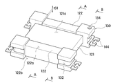
도 1은 본 발명의 일 실시예에 따른 저주파 안테나 모듈을 나타낸 개략도,
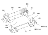
도 2는 도 1에서 복수 개의 코일이 제거된 상태를 나타낸 도면,
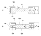
도 3은 도 2의 저면을 나타낸 도면,
도 4는 도 2에서 와이어 가이드와 자성체 코어가 분리된 상태를 나타낸 도면,
도 5는 도 2에서 A-A방향과 B-B방향 단면도,
도 6은 본 발명의 다른 실시예에 따른 저주파 안테나 모듈을 나타낸 개략도,
도 7은 도 6에서 복수 개의 코일이 제거된 상태를 나타낸 도면,
도 8은 도 7의 저면을 나타낸 도면,
도 9는 도 7에서 와이어 가이드와 자성체 코어가 분리된 상태를 나타낸 도면,
도 10은 본 발명의 다른 실시예에 따른 저주파 안테나 모듈에 적용되는 자성체 코어의 삽입홈과 와이어 가이드의 결합구를 확대한 도면,
도 11은 본 발명의 다른 실시예에 따른 저주파 안테나 모듈에 적용되는 자성체 코어의 삽입홈과 와이어 가이드의 결합구의 결합전 상태와 결합 후 상태를 나타낸 도면,
도 12는 도 7의 C-C방향 단면도, 그리고,
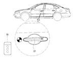
도 13은 본 발명에 따른 저주파 안테나 모듈을 이용한 키리스 엔트리 시스템의 예시도이다.1 is a schematic view of a low-frequency antenna module according to an embodiment of the present invention,
FIG. 2 is a view showing a state in which a plurality of coils are removed in FIG. 1,
Figure 3 is a bottom view of Figure 2,
FIG. 4 is a view showing a state in which the wire guide and the magnetic core are separated from each other in FIG.
FIG. 5 is a cross-sectional view taken along line AA and BB in FIG. 2,
6 is a schematic view of a low frequency antenna module according to another embodiment of the present invention,
FIG. 7 is a view showing a state where a plurality of coils are removed in FIG. 6;
Figure 8 is a bottom view of Figure 7,
FIG. 9 is a view showing a state in which the wire guide and the magnetic material core are separated from each other in FIG. 7;
10 is an enlarged view of a coupling hole of a wire guide and an insertion groove of a magnetic core, which is applied to a low frequency antenna module according to another embodiment of the present invention;
11 is a view showing a state before coupling and a state after coupling between a coupling groove of a wire guide and an insertion groove of a magnetic core applied to a low frequency antenna module according to another embodiment of the present invention;
12 is a cross-sectional view in the CC direction of Fig. 7,
FIG. 13 is an illustration of a keyless entry system using a low-frequency antenna module according to the present invention.
이하, 첨부한 도면을 참고로 하여 본 발명의 실시예에 대하여 본 발명이 속하는 기술분야에서 통상의 지식을 가진 자가 용이하게 실시할 수 있도록 상세히 설명한다. 본 발명은 여러 가지 상이한 형태로 구현될 수 있으며 여기에서 설명하는 실시예에 한정되지 않는다. 도면에서 본 발명을 명확하게 설명하기 위해서 설명과 관계없는 부분은 생략하였으며, 명세서 전체를 통하여 동일 또는 유사한 구성요소에 대해서는 동일한 참조부호를 부가한다.Hereinafter, exemplary embodiments of the present invention will be described in detail with reference to the accompanying drawings, which will be readily apparent to those skilled in the art to which the present invention pertains. The present invention may be embodied in many different forms and is not limited to the embodiments described herein. In order to clearly illustrate the present invention, parts not related to the description are omitted, and the same reference numerals are assigned to the same or similar components throughout the specification.
본 발명의 일 실시예에 따른 저주파 안테나 모듈(100,200)은 도 1 및 도 6에 도시된 바와 같이 복수 개의 코일(111,112,113), 자성체 코어(120,220) 및 복수 개의 와이어 가이드(130,230)를 포함한다.1 and 6, the low
상기 복수 개의 코일(111,112,113)은 소정의 주파수 대역에서 신호를 발생시켜 저주파 통신을 수행하기 위한 것으로, 제1코일(111), 제2코일(112) 및 제3코일(113)을 포함하며, 3개의 코일이 서로 직교하는 X축, Y축 및 Z축을 중심으로 각각 권선됨으로써 서로 직교하도록 배치된다.The plurality of
일례로, 상기 제1코일(111)은 X축을 중심으로 복수 회 권선될 수 있고, 상기 제2코일(112)은 Y축을 중심으로 복수 회 권선될 수 있으며, 상기 제3코일(113)은 Z축을 중심으로 복수 회 권선될 수 있다. 이에 따라, 3개의 코일(111,112,113)이 서로 직교하도록 배치됨으로써 저주파 안테나 모듈의 방향에 관계없이 항상 안정된 상태로 외부에서 송출된 신호를 수신할 수 있게 된다. 여기서, 상기 복수 개의 코일(111,112,113)은 소정의 선경을 갖는 구리선의 외부에 에나멜 절연이 이루어진 에나멜선이 사용될 수 있다.For example, the
상기 자성체 코어(120,220)는 서로 직교하게 배치되는 3개의 코일(111,112,113)의 내부에 배치되어 상기 3개의 코일(111,112,113) 중 일부 또는 전체를 지지할 수 있도록 한다.The
이를 위해, 상기 자성체 코어(120,220)는 상기 제1코일(111)의 권선되는 제1몸체(121)와, 상기 제2코일(112)이 권선되는 한 쌍의 제2몸체(122)를 포함하며, 상기 한 쌍의 제2몸체(122)는 Y축 방향과 평행한 방향으로 소정의 길이를 갖추어 상기 제1몸체(121)의 양 단부측에 각각 일체로 형성될 수 있다.The
이에 따라, 상기 제1몸체(121)의 표면을 따라 X축을 중심으로 제1코일(111)을 복수 회 권선하고, 상기 한 쌍의 제2몸체(122)를 둘러싸도록 Y축을 중심으로 제2코일(112)을 복수 회 권선하게 되면 상기 제1코일(111) 및 제2코일(112)은 서로 직교하도록 배치된다.The
이때, 상기 제1몸체(121) 및 제2몸체(122)는 서로 동일한 높이 또는 두께를 갖도록 형성될 수도 있지만, 상기 한 쌍의 제2몸체(122)는 상기 제1몸체(121)의 두께(t1)보다 상대적으로 두꺼운 두께(t2)를 갖도록 형성될 수 있으며, 상기 한 쌍의 제2몸체(122)가 상기 제1몸체(121)의 상부면과 하부면으로부터 각각 일정높이 돌출되도록 상기 제1몸체(121)에 일체로 형성될 수 있다.The
더불어, 상기 제1몸체(121)의 상부면과 하부면으로부터 각각 돌출되는 제2몸체(122)의 돌출두께(t21)는 상기 제1몸체(121)에 권선되는 제1코일(111)의 전체두께와 동일한 두께를 가질 수 있다.The protruding thickness t21 of the
이에 따라, 상기 자성체 코어(120,220)는 상기 제1몸체(121)의 상부면 및 한 쌍의 제2몸체(122)의 돌출면, 상기 제1몸체(121)의 하부면 및 한 쌍의 제2몸체(122)의 돌출면에 의해 상기 제2몸체(122)의 상부면과 하부면으로부터 일정깊이 인입되는 수용홈(121a,121b)이 형성됨으로써 상기 제1몸체(121)에 권선되는 제1코일(111)의 두께를 수용할 수 있게 된다.The
그러나, 상기 제2몸체(122)의 전체두께(t2)를 이에 한정하는 것은 아니며, 상기 제2몸체(122)의 전체두께(t2)는 상기 제1몸체(121)의 상부면과 하부면으로부터 각각 돌출되는 제2몸체(122)의 돌출두께(t21)가 상기 제1몸체(121)에 권선되는 제1코일(111)의 전체두께보다 상대적으로 두꺼운 두께를 가질 수도 있음을 밝혀둔다.However, the overall thickness t2 of the
여기서, 상기 제1코일(111)의 전체두께는 상기 제1코일(111)의 선경일 수도 있고, 상기 제1코일(111)이 상기 제1몸체(121)의 표면을 따라 복수 개의 층으로 중첩되도록 권선되는 경우 권선된 코일의 전체두께일 수 있다.The total thickness of the
한편, 상기 자성체 코어(120,220)는 Mn-Zn, Ni-Zn, Ni-Cu-Zn와 같은 소결 페라이트가 사용될 수 있지만 이에 한정하는 것은 아니며, 더스트 코어가 사용될 수도 있으며 인덕터 코어를 형성할 수 있도록 자성을 갖는 재질이면 모두 사용될 수 있음을 밝혀둔다. 더불어, 상기 자성체 코어(120,220)는 비정질 또는 나노 결정 구조를 갖는 연자성 합금이 사용될 수도 있다.Sintered ferrites such as Mn-Zn, Ni-Zn, and Ni-Cu-Zn may be used for the
상기 복수 개의 와이어 가이드(130,230)는 상기 제3코일(113)이 Z축을 중심으로 권선되어 상기 제1코일(111) 및 제2코일(112)과 각각 수직하게 배치될 수 있도록 하기 위한 것이다.The plurality of wire guides 130 and 230 are for winding the
이를 위해, 상기 복수 개의 와이어 가이드(130,230)는 상기 자성체 코어(120,220)의 테두리를 따라 소정의 간격을 두고 이격배치될 수 있다. 일례로, 상기 복수 개의 와이어 가이드(130,230)는 상기 자성체 코어(120,220)가 대략 직육면체 형상으로 구비되는 경우 상기 자성체 코어(120,220)의 네 모서리 측에 배치될 수 있다.For this purpose, the plurality of wire guides 130 and 230 may be spaced apart from each other at a predetermined interval along the rim of the
이에 따라, 상기 제3코일(113)을 Z축을 중심으로 복수 개의 와이어 가이드(130,230)를 둘러싸도록 권선하게 되면, 상기 자성체 코어(120,220)에 권선된 제1코일(111) 및 제2코일(112)과 서로 직교하도록 배치된다.Accordingly, when the
여기서, 상기 복수 개의 와이어 가이드(130,230)는 절연체로 이루어질 수 있다.Here, the plurality of wire guides 130 and 230 may be formed of an insulator.
이때, 상기 복수 개의 와이어 가이드(130,230)는 상기 제3코일(113)과 접촉되는 영역에 상기 제3코일(113)의 두께를 수용하기 위한 코일배치홈(132)이 내측으로 인입형성될 수 있다.At this time, the plurality of wire guides 130 and 230 may be formed with a
더불어, 상기 코일배치홈(132)의 깊이(d)는 상기 제3코일(113)의 전체두께와 동일한 크기를 가질 수 있다.In addition, the depth d of the
이에 따라, 상기 제3코일(113)의 전체두께가 상기 코일배치홈(132)에 의해 수용됨으로써 상기 제3코일(113)이 외측으로 돌출되지 않게 된다.As a result, the entire thickness of the
그러나, 상기 코일배치홈(132)의 깊이(d)를 이에 한정하는 것은 아니며, 상기 제3코일(113)의 전체두께보다 상대적으로 두꺼운 두께를 가질 수도 있음을 밝혀둔다.However, it should be noted that the depth d of the
여기서, 상기 제3코일(113)의 전체두께는 상기 제3코일(113)의 선경일 수도 있고, 상기 제3코일(113)이 복수 개의 층으로 중첩되도록 권선되는 경우 권선된 코일의 전체두께일 수 있다.The total thickness of the
한편, 상기 복수 개의 와이어 가이드(130,230)는 상기 제2몸체(122)와 서로 동일한 높이 또는 두께를 갖도록 형성될 수도 있지만, 상기 복수 개의 와이어 가이드(130,230)는 상기 제2몸체(121)의 전체두께(t2)보다 상대적으로 두꺼운 두께(t3)를 갖도록 형성될 수 있으며, 상기 자성체 코어(120)와의 결합시 상기 복수 개의 와이어 가이드(130,230)는 상기 제2몸체(122)의 상부면과 하부면으로부터 각각 일정높이 돌출되도록 구비될 수 있다.The plurality of wire guides 130 and 230 may be formed to have the same height or thickness as the
더불어, 상기 제2몸체(122)의 상부면과 하부면으로부터 각각 돌출되는 상기 와이어 가이드(130,230)의 돌출두께(t31)는 상기 제2몸체(122)에 권선되는 제2코일(112)의 전체두께와 동일한 두께를 가질 수 있다.The protruding thickness t31 of the wire guides 130 and 230 protruding from the upper and lower surfaces of the
이에 따라, 상기 와이어 가이드(130,230)는 상기 제2몸체(122)의 상부면 및 와이어 가이드(130,230)의 돌출면, 상기 제2몸체(122)의 하부면 및 와이어 가이드(130,230)의 돌출면에 의해 상기 와이어 가이드(130,230)의 상부면과 하부면으로부터 일정깊이 인입되는 수용홈(122a,122b)이 형성됨으로써 상기 제2몸체(122)에 권선되는 제2코일(112)의 두께를 수용할 수 있게 된다.The wire guides 130 and 230 are disposed on the upper surface of the
그러나, 상기 와이어 가이드(130,230)의 전체두께(t3)를 이에 한정하는 것은 아니며, 상기 와이어 가이드(130,230)의 전체두께(t3)는 상기 제2몸체(121)의 상부면과 하부면으로부터 각각 돌출되는 와이어 가이드(130,230)의 돌출두께(t31)가 상기 제2몸체(122)에 권선되는 제2코일(112)의 전체두께보다 상대적으로 두꺼운 두께를 가질 수도 있음을 밝혀둔다.However, the total thickness t3 of the wire guides 130 and 230 is not limited thereto, and the total thickness t3 of the wire guides 130 and 230 may be set such that the entire thickness t3 of the wire guides 130 and 230 protrudes from the upper surface and the lower surface of the
여기서, 상기 제2코일(112)의 전체두께는 상기 제2코일(112)의 선경일 수도 있고, 상기 제2코일(112)이 상기 한 쌍의 제2몸체(122)를 감싸도록 복수 개의 층으로 중첩되도록 권선되는 경우 권선된 코일의 전체두께일 수 있다.Here, the total thickness of the
한편, 상기 복수 개의 와이어 가이드(130,230)는 외부와의 전기적인 연결을 위한 적어도 하나의 단자(142)와, 상기 복수 개의 코일(111,112,113) 중 어느 하나의 코일(111,112,113)의 단부를 연결하기 위한 적어도 하나의 와이어 결속구(144)를 포함할 수 있으며, 상기 단자(142)와 와이어 결속구(144)가 서로 전기적으로 연결될 수 있다.The plurality of wire guides 130 and 230 may include at least one
일례로, 상기 단자(142)는 상기 와이어 가이드(130,230)의 저면에 형성될 수 있고, 상기 와이어 결속구(144)는 상기 와이어 가이드(130,230)의 측면에 각각 형성될 수 있으며, 각각의 와이어 가이드(130,230)에 두 개의 단자(142)와 두 개의 와이어 결속구(144)가 각각 형성되고 두 개의 단자(142) 및 두 개의 와이어 결속구(144)가 일대일로 매칭되어 서로 전기적으로 연결될 수 있다.For example, the
이때, 상기 와이어 결속구(144) 및 서로 매칭되는 단자(142)는 각각의 부재로 이루어져 서로 연결될 수도 있지만, 소정의 면적과 길이를 갖는 하나의 도전성 부재(140)로 형성될 수 있다(도 3 및 도 8 참조).At this time, the
이에 따라, 상기 복수 개의 코일(111,112,113)의 양단부를 복수 개의 와이어 결속구(144)에 개별적으로 연결하게 되면, 상기 코일(111,112,113)의 양단부는 각각의 단자(142)와 서로 전기적으로 연결된다. Thus, when both ends of the plurality of
일례로, 도 1 및 도 6에 도시된 바와 같이 상기 제1코일(111)의 양단부 중 어느 하나는 상기 복수 개의 와이어 가이드 중 제1와이어 가이드(130a,230a)에 형성되는 제1와이어 결속구(144a)에 연결될 수 있고 타단부는 상기 제1와이어 가이드(130a,230a)와 대각방향에 배치되는 제3와이어 가이드(130c,230c)에 형성되는 제5와이어 결속구(144e)와 연결될 수 있다.For example, as shown in FIGS. 1 and 6, one of both ends of the
또한, 상기 제2코일(112)의 양단부 중 어느 하나는 상기 제1와이어 가이드(130a,230a)에 형성되는 제2와이어 결속구(144b)에 연결될 수 있고 타단부는 상기 제1와이어 가이드(130a,230a)와 Y축 방향을 따라 이격배치되는 제4와이어 가이드(130d,230d)에 형성되는 제7와이어 결속구(144g)에 연결될 수 있다. One of both ends of the
더불어, 상기 제3코일(113)의 양단부 중 어느 하나는 상기 제1와이어 가이드(130a,230a)와 X축 방향을 따라 이격배치되는 제2와이어 가이드(130b,230b)에 형성되는 제4와이어 결속구(144d)에 연결될 수 있고 타단부는 상기 제4와이어 가이드(130d,230d)에 형성되는 제8와이어 결속구(144h)에 연결될 수 있다. In addition, any one of the opposite ends of the
그러나, 상기 복수 개의 코일(111,112,113)의 양단부와 각각 연결되는 와이어 결속구(144)의 위치를 이에 한정하는 것은 아니며, 설계조건에 따라 다양하게 변경될 수 있음을 밝혀둔다. However, it should be understood that the positions of the
한편, 상기 복수 개의 와이어 가이드(130,230) 중 어느 하나는 기준위치를 표시하기 위한 적어도 하나의 마크부(134)가 형성될 수 있다. 여기서, 상기 기준위치는 복수 개의 단자 중 제1와이어 결속구(144a)와 직접 연결되는 단자(142a)의 위치일 수 있다.At least one
일례로, 상기 마크부(134)는 상기 제1와이어 결속구(144a)와 연결되는 단자(142a)가 형성되는 제1와이어 가이드(130a,230a)의 상면에 소정의 깊이를 갖는 수용홈의 형태로 구비될 수 있다. For example, the
그러나, 상기 마크부(134)를 이에 한정하는 것은 아니며 지시선, 색상, 도형 등과 같이 작업자가 육안으로 용이하게 식별할 수 있는 형태라면 모두 사용 가능함을 밝혀둔다. However, it should be noted that the
이와 같이, 본 발명에 따른 저주파 안테나 모듈(100,200)은 복수 개의 와이어 결속구(144) 측에 코일(111,112,113)의 양단부측이 각각 개별적으로 연결되고 각각의 와이어 결속구(144)가 서로 매칭된 단자(142)와 전기적으로 연결됨으로써 의 하부면 측에 회로기판(미도시)을 배치한 후 상기 복수 개의 와이어 가이드(130,230)에 각각 형성된 단자(142)를 회로기판에 실장하게 되면, 상기 회로기판과 복수 개의 코일(111,112,113)이 서로 전기적으로 연결된 단자(142) 및 와이어 결속구(144)를 통해 통전되어 외부로부터 제공되는 전원이 회로기판을 통해 각각의 코일(111,112,113) 측으로 공급될 수 있게 된다.As described above, the low-
즉, 본 발명에 따른 저주파 안테나 모듈(100,200)에 적용되는 복수 개의 와이어 가이드(130,230)는 Z축을 중심으로 권선되는 제3코일(113)을 지지하는 역할과 더불어, 절연체로 이루어져 외부로 노출되고 서로 전기적으로 연결된 단자(142) 및 와이어 결속구(144)를 제외한 나머지 부분을 절연함으로써 상기 단자(142) 및 와이어 결속구(144)를 통해 복수 개의 코일(111,112,113)을 외부와 전기적으로 연결하기 위한 접속단자의 역할을 동시에 수행할 수 있게 된다.That is, the plurality of wire guides 130 and 230 applied to the low-
이로 인해, 상기 복수 개의 코일(111,112,113)과 회로기판을 통전시키기 위한 별도의 구조가 불필요하므로 전체적인 구성이 단순하고, 서로 직교하는 제1코일(111), 제2코일(112) 및 제3코일(113)의 전체두께를 수용하여 각각의 코일에 두께에 해당하는 만큼의 크기를 줄일 수 있게 되므로 박형화를 구현할 수 있게 된다.Therefore, a separate structure for energizing the plurality of
여기서, 상기 회로기판의 일면에는 상기 복수 개의 단자(142)와 대응되는 접속단자(미도시)가 형성될 수 있다. 더불어, 상기 복수 개의 단자(142) 및 와이어 결속구(144)는 상기 복수 개의 와이어 가이드(130,230)에 모두 구비될 수도 있고, 복수 개의 와이어 가이드(130,230) 중 일부에만 선택적으로 구비될 수도 있으며, 각각의 와이어 가이드(130,230)에 형성되는 단자(142) 및 와이어 결속구(144)의 개수는 동일한 개수를 가질 수도 있고 서로 다른 개수를 가질 수도 있음을 밝혀둔다. 다만, 복수 개의 와이어 가이드(130,230)에 형성되는 단자(142) 및 와이어 결속구(144)의 총 개수는 서로 직교하게 배치되는 3개의 코일(111,112,113)의 양단부가 각각 개별적으로 연결될 수 있도록 6개 이상이면 족함을 밝혀둔다.Here, connection terminals (not shown) corresponding to the plurality of
한편, 상기 도전성 부재(140)는 인서트 몰딩을 통해 상기 와이어 가이드(144)와 일체화될 수 있다.Meanwhile, the
일례로, 상기 도전성 부재(140)는 상기 와이어 가이드(130,230)의 저면에 일단부측이 노출되어 상기 단자(142)를 형성하고 타단부 측이 상기 와이어 가이드(130,230)의 측면에 노출되어 상기 와이어 결속구(144)를 형성하도록 상기 와이어 가이드(130,230)와 일체화됨으로써 상기 단자(142) 및 와이어 결속구(144)를 제외한 나머지 부분이 내부에 매립된 상태일 수 있다. 여기서, 상기 와이어 결속구(144)는 코일(111,112,113)의 단부를 용이하게 연결할 수 있도록 상기 와이어 가이드(130,230)의 측면으로부터 일정길이 외측으로 돌출될 수 있다. One end of the
이에 따라, 상기 도전성 부재(140)는 통전을 위한 단자(142) 및 와이어 결속구(144)를 제외한 나머지 부분이 절연체로 이루어진 와이어 가이드(130,230)에 매립되어 표면이 절연될 수 있다.The
한편, 본 발명에 따른 저주파 안테나 모듈(100,200)은 복수 개의 와이어 가이드(130,230)가 상기 자성체 코어(120,220)에 대하여 수평한 방향(XY 평면과 평행한 방향)으로 결합될 수 있으며, 상기 자성체 코어(120,220)에 대하여 완전히 고정된 형태로 결합될 수도 있고 분리가능하게 결합될 수도 있다.In the low
일 실시예로써, 상기 복수 개의 와이어 가이드(130)는 일측에 소정의 면적을 갖는 결합홈(136)이 내측으로 인입형성됨으로써 상기 결합홈(136)에 자성체 코어(120)의 일부가 삽입되는 형태일 수 있다(도 2 내지 도 5 참조).In one embodiment, the plurality of wire guides 130 may have a shape in which a part of the
여기서, 상기 결합홈(136)에 삽입되는 자성체 코어(120)의 일부는 자성체 코어(120)의 모서리 측일 수 있다.Here, a part of the
이를 위해, 상기 자성체 코어(120)는 모서리 측에 상기 결합홈(136)과 대응되는 돌출편(123)이 형성될 수 있다.To this end, the
일례로, 상기 제1몸체(121)는 상기 한 쌍의 제2몸체(122)보다 상대적으로 긴 길이를 갖도록 구비되고, 상기 한 쌍의 제2몸체(122)가 상기 제1몸체(121)의 길이 중간에 배치되어 상기 제1몸체(121)에 대하여 일체로 형성됨으로써 상기 제2몸체(122)의 양 단부 측에 서로 이웃하는 상기 제2몸체(122)의 측면과 제1몸체(121)의 측면에 규정되는 소정의 공간이 형성될 수 있으며, 상기 소정의 공간에 상기 돌출편(123)이 각각 배치될 수 있다. 이때, 상기 돌출편(123)은 X축과 Y축에 의해 규정되는 평면과 평행하도록 소정의 면적과 두께를 갖는 판상의 형태로 구비될 수 있다.For example, the
이에 따라, 상기 와이어 가이드(130)를 자성체 코어(120)에 대하여 수평한 방향(XY 평면과 평행한 방향)으로 이동시켜 상기 돌출편(123)이 와이어 가이드(130)에 형성된 결합홈(136) 측으로 삽입하게 되면 와이어 가이드(130)는 자성체 코어(120)에 간편하게 결합된다.The
여기서, 상기 돌출편(123)은 상기 소정의 공간을 규정하는 제1몸체(121)의 측면 및 제2몸체(122)의 측면 중 어느 하나의 측면과 일체로 형성될 수도 있지만, 내구성을 높일 수 있도록 상기 제1몸체(121)의 측면 및 제2몸체(122)의 측면과 접하는 두면과 각각 일체로 형성될 수 있다.The protruding
이때, 상기 돌출편(123)은 상기 제2몸체(122)의 두께(t2)보다 상대적으로 얇은 두께를 갖는 제1몸체(121)의 두께(t1)보다 더 얇은 두께(t4)를 가지도록 형성될 수 있다. 이에 따라, 상기 돌출편(123)의 상부면은 상기 제1몸체(121)의 상부면보다 상대적으로 낮은 위치에 형성되며, 상기 돌출편(123)의 하부면은 상기 제1몸체(121)의 하부면보다 상대적으로 높은 위치에 형성될 수 있다. At this time, the projecting
이로 인해, 상기 돌출편(123)의 상부면 및 하부면은 상기 제1몸체(121)의 상부면 및 하부면과 제2몸체(122)의 상부면 및 하부면에 대하여 각각 단차구조로 형성함으로써 상기 와이어 가이드(130)를 결합하는 과정에서 와이어 가이드(130)의 삽입 깊이를 제한함으로써 와이어 가이드(130)가 제1몸체(121)의 상부면과 하부면 또는 제2몸체(122)의 상부면과 하부면을 덮는 것을 미연에 방지하게 된다.Therefore, the upper surface and the lower surface of the protruding
이에 따라, 상기 제1몸체(121)에 권선되는 제1코일(111)의 권선면적 또는 제2몸체(122)를 둘러싸도록 권선되는 제2코일(112)의 권선면적이 최초의 설계면적보다 줄어드는 것을 방지할 수 있게 된다.The winding area of the
이때, 상호 결합되는 돌출편(123) 및 결합홈(136)의 접촉면 상에는 접착부재(미도시)가 배치됨으로써 상기 돌출편(123) 및 결합홈(136)을 을 매개로 결합되는 와이어 가이드(130)가 자성체 코어(120)로부터 분리되는 것을 방지할 수 있다.At this time, an adhesive member (not shown) is disposed on the contact surfaces of the protruding
즉, 상기 결합홈(136)에 돌출편(123)이 삽입되는 경우 상기 와이어 가이드(130)는 돌출편(123)에 의해 체결방향과 수직한 자성체 코어(120)의 상,하 방향(Z축 방향)으로의 유동은 방지되나 체결방향과 평행한 수평방향(XY평면과 평행한 방향)에 대해서는 유동이 발생되어 상기 결합홈(136)과 돌출편(123)의 결합상태가 해제될 수 있다. 본 실시예에서는 돌출편(123) 및 결합홈(136)의 접촉면 상에 접착부재(미도시)를 배치함으로써 상기 결합홈(136)과 돌출편(123)의 결합상태가 해제되는 것을 방지할 수 있다.That is, when the protruding
다른 실시예로써, 상기 복수 개의 와이어 가이드(230)는 와이어 가이드(230)의 높이방향(Z축 방향)을 따라 소정의 길이를 갖추고 외측으로 돌출형성되는 적어도 하나의 결합구(232)가 구비되고, 상기 자성체 코어(220) 측에는 일면으로부터 높이방향(Z축 방향)을 따라 인입형성되는 삽입홈(223a,223b)이 형성됨으로써 상기 삽입홈(223a,223b)에 결합구(232)가 삽입되는 형태일 수 있다(도 7 내지 도 12 참조).As another example, the plurality of wire guides 230 may include at least one
여기서, 상기 삽입홈(223a,223b)은 상기 자성체 코어(220)의 모서리 측에 형성될 수 있다.Here, the
이때, 상기 결합구(232)는 하나로 구비될 수도 있지만, 상기 와이어 가이드(230)의 높이방향(Z축 방향)을 따라 소정의 간격을 두고 이격배치되는 한 쌍으로 구비될 수 있다. 이와 같은 경우, 상기 삽입홈(223a,223b) 역시 상기 자성체 코어(220)의 상부면과 하부면으로부터 높이방향(Z축 방향)을 따라 각각 인입형성되는 한 쌍으로 구비됨으로써 상기 한 쌍의 결합구(232)가 한 쌍의 삽입홈(223a,223b) 측에 수평한 방향(XY 평면과 평행한 방향)으로 진입하여 각각 삽입될 수 있도록 한다. At this time, the
여기서, 상기 자성체 코어(220)의 높이 방향(Z축 방향)을 따라 상,하로 배치되는 한 쌍의 삽입홈(223a,223b) 사이에는 소정의 면적 및 두께를 갖는 걸림편(224)이 형성될 수 있으며, 상기 한 쌍의 삽입홈(223a,223b)에 한 쌍의 결합구(232)가 각각 삽입되는 경우 상기 한 쌍의 결합구(232)의 일단부 측이 상기 걸림편(224)의 상부면 및 하부면과 각각 접하도록 배치될 수 있다. The engaging
이에 따라, 상기 한 쌍의 삽입홈(223a,223b)에 각각 삽입된 한 쌍의 결합구(232)는 일단부측이 각각 걸림편(224)의 상부면과 하부면에 접함으로써 상기 걸림편(224)의 상,하부면과 수직한 방향(Z축 방향)으로 유동되는 것이 원천적으로 차단된다.The pair of
이로 인해, 별도의 접착부재를 사용하지 않더라도 상기 삽입홈(223a,223b)에 삽입된 결합구(232)의 위치가 고정되어 상,하 방향(Z축 방향)으로의 이동이 제한됨으로써 본 발명에 따른 저주파 안테나 모듈(200)이 작업과정이나 운반과정 중에 뒤집히거나 흔들림이 발생하더라도 상기 와이어 가이드(230)가 정해진 위치에 결합된 상태로 유지될 수 있게 된다.Therefore, even if a separate adhesive member is not used, the position of the
이때, 본 실시예에서 상기 결합구(232)는 자성체 코어(220)의 수평방향(XY 평면과 평행한 방향)과 평행한 방향으로 상기 삽입홈(223a,223b)에 원활하게 삽입될 수 있도록 외력에 의해 탄성적인 변형이 가능하도록 구비될 수 있다.In this embodiment, in order to smoothly insert the
일례로써, 상기 삽입홈(223a,223b)은 반원의 면적을 초과하는 제1원호부(223c)를 포함하는 단면형상을 갖추어 일측이 개방되도록 형성되고, 상기 결합구(232)는 반원면적 미만의 제2원호부(232c)를 포함하는 단면형상을 갖는 한 쌍의 탄성편(232a,232b)으로 구비될 수 있다. 이때, 상기 한 쌍의 탄성편(232a,232b)은 상기 제2원호부(232c)를 제외한 다른 면이 서로 마주하도록 소정의 간격을 두고 이격배치된다.For example, the
이에 따라, 상기 한 쌍의 탄성편(232a,232b)의 단부를 상기 삽입홈(223a,223b) 측에 밀어넣게 되면 접촉에 의해 상기 탄성편 측으로 외력이 가해짐으로써 서로 마주하는 한 쌍의 탄성편(232a,232b) 사이의 간격이 좁아지게 된다. 이로 인해, 상기 한 쌍의 탄성편은 상기 삽입홈(223a,223b)의 개방된 부분을 통하여 상기 삽입홈(223a,223b)의 내부로 삽입될 수 있다. 이후, 상기 한 쌍의 탄성편(232a,232b)에 가해진 외력을 제거되면 상기 한 쌍의 탄성편(232a,232b)이 원위치로 복귀함에 따라 상기 삽입홈(223a,223b)의 제1원호부(223c) 중 반원을 초과하는 부분에 의하여 구속됨으로써 상기 한 쌍의 탄성편(232a,232b)이 상기 삽입홈(223a,223b)의 외측으로 이탈되는 것을 방지할 수 있게 된다(도 11 참조).Accordingly, when the end portions of the pair of
반대로, 상기 삽입홈(223a,223b)에 삽입된 한 쌍의 탄성편(232a,232b)을 분리하고자 하는 경우 상기 한 쌍의 탄성편(232a,232b)을 잡아당기게 되면 상기 삽입홈의 개구부 측과의 접촉에 의해 외력이 발생하여 서로 마주하는 한 쌍의 탄성편(232a,232b) 사이의 간격이 좁아짐으로써 상기 삽입홈(223a,223b)의 개방된 부분을 통하여 상기 삽입홈(223a,223b)으로부터 한 쌍의 탄성편(232a,232b)을 용이하게 이탈시킬 수 있게 된다(도 11 참조).Conversely, when a pair of
이로 인해, 각각의 와이어 가이드(230)를 상기 자성체 코어(220)에 체결하거나 분리하는 것이 가능하게 되므로, 와이어 가이드(230)의 교체가 필요한 경우 간편하게 분리할 수 있게 된다.As a result, each
여기서, 상기 제1원호부(223c) 및 제2원호부(232c)는 서로 동일한 반지름을 갖도록 형성됨으로써 상기 한 쌍의 탄성편(232a,232b)이 상기 삽입홈(223a,223b)에 삽입되는 경우 상기 탄성편(232a,232b)에 포함되는 제1원호부(223c)의 외면과 상기 제2원호부(232c)에 해당하는 삽입홈(223a,223b)의 내면이 서로 접촉되도록 함으로써 마찰력에 의한 구속력을 증가시킬 수 있도록 한다.The first
한편, 본 발명에 따른 저주파 안테나 모듈(100,200)은 적어도 일면에 상기 복수 개의 코일(111,112,113)이 외부로 노출되는 것을 방지하기 위한 별도의 보호부재(미도시)가 구비될 수 있다.Meanwhile, the low-
이러한, 보호부재는 가요성을 갖는 보호필름의 형태로 구비될 수도 있고, 강성을 갖는 소재로 이루어질 수도 있다.Such a protective member may be provided in the form of a flexible protective film or may be made of a rigid material.
또한, 상기 보호부재는 저주파 안테나 모듈(100,200)의 일면, 일례로 상부면만을 덮는 형태로 구비될 수도 있고, 상기 와이어 가이드(130,230)의 하부면에 형성된 단자(142)를 제외한 나머지 부분, 즉, 상부면과 측면을 모두 덮는 형태로 구비될 수도 있다.The protection member may be formed on one surface of the low
상술한 본 발명에 따른 저주파 안테나 모듈(100,200)은 저주파 송신기와 저주파 수신기를 포함하는 키리스 엔트리 시스템에 적용될 수 있다(도 13 참조).The low
일례로, 상기 저주파 안테나 모듈(100,200)은 사용자가 휴대하는 스마트키(10), 스마트폰과 같은 휴대단말기 또는 스마트 워치와 같은 웨어러블 디바이스에 내장된 키 포브(KEY FOB)에 설치될 수 있다.For example, the low-
여기서, 상기 키 포브(KEY FOB)에는 저주파 안테나 모듈(100,200)을 포함하는 저주파(LF) 수신기, 3D 액티브 이모빌라이저(immobilizer) 및 마이크로콘트롤러가 구비될 수 있다.Here, the KEY FOB may include a low frequency (LF) receiver including a low
이에 따라, 스마트 키(10)에 탑재된 키 포브(KEY FOB)와 차량에 탑재된 제어부 사이에는 예를 들어, 22kHz 대역의 저주파(LF) 통신이 이루어짐으로써 무선으로 차량의 도어 또는 스티어링(steering) 중 적어도 하나의 로크(lock) 또는 언로크(unlock)가 제어될 수 있다.Accordingly, low frequency (LF) communication in the 22 kHz band is performed between the key fob mounted on the
더불어, 상술한 저주파 안테나 모듈(100,200)은 운전자가 별도의 기계적인 키의 삽입이나 조작 없이, 전자 인증되어 있는 상태에서 엔진의 시동, 작동 및 정지를 수행하여 자동차를 운행할 수 있는 키리스 스타트 시스템에도 적용될 수 있음을 밝혀둔다.In addition, the low-
또한, 상술한 저주파 안테나 모듈(100,200)은 키리스 엔트리 시스템을 구성하는 저주파 송신기로 구현될 수도 있음을 밝혀둔다.It is also noted that the low-
이상에서 본 발명의 일 실시예에 대하여 설명하였으나, 본 발명의 사상은 본 명세서에 제시되는 실시 예에 제한되지 아니하며, 본 발명의 사상을 이해하는 당업자는 동일한 사상의 범위 내에서, 구성요소의 부가, 변경, 삭제, 추가 등에 의해서 다른 실시 예를 용이하게 제안할 수 있을 것이나, 이 또한 본 발명의 사상범위 내에 든다고 할 것이다.While the present invention has been particularly shown and described with reference to exemplary embodiments thereof, it is to be understood that the invention is not limited to the disclosed exemplary embodiments, It will be understood by those skilled in the art that various changes in form and details may be made therein without departing from the spirit and scope of the invention as defined by the appended claims.
100,200 : 저주파 안테나 모듈
111 : 제1코일
112 : 제2코일
113 : 제3코일
120,220 : 자성체 코어
121 : 제1몸체
121a,121b : 수용홈
122 : 제2몸체
122a,122b : 수용홈
123 : 돌출편
130,230 : 와이어 가이드
132 : 코일배치홈
134 : 마크부
136 : 결합홈
232c : 제2원호부
140 : 도전성 부재
142 : 단자
144 : 와이어 결속구100, 200: low frequency antenna module 111: first coil
112: second coil 113: third coil
120, 220: magnetic core 121: first body
121a, 121b: receiving groove 122: second body
122a, 122b: receiving groove 123:
130, 230: wire guide 132: coil placement groove
134: mark portion 136: engaging groove
232c: second arc portion 140: conductive member
142: Terminal 144:
Claims (23)
상기 X축을 중심으로 제1코일이 권선되고 상기 Y축을 중심으로 제2코일이 권선되는 자성체 코어; 및
외부와의 전기적인 연결을 위한 적어도 하나의 단자와 상기 코일의 양 단부 중 어느 하나를 연결하기 위한 적어도 하나의 와이어 결속구를 갖추어 상기 자성체 코어에 대하여 수평한 방향으로 결합되며, 상기 Z축을 중심으로 제3코일이 권선될 수 있도록 상기 자성체 코어의 테두리를 따라 이격배치되는 복수 개의 와이어 가이드;를 포함하는 저주파 안테나 모듈.A low-frequency antenna module in which a plurality of coils are wound around an X-axis, a Y-axis, and a Z-axis orthogonal to each other,
A magnetic core in which a first coil is wound around the X-axis and a second coil is wound around the Y-axis; And
At least one terminal for electrical connection to the outside and at least one wire binding port for connecting any one of the two ends of the coil is coupled in a horizontal direction with respect to the magnetic core, And a plurality of wire guides spaced apart along the rim of the magnetic core so that the third coil can be wound.
상기 자성체 코어는 상기 제1코일이 권선되는 제1몸체와, 상기 제1몸체와 일체로 형성되어 상기 제2코일이 권선되는 한 쌍의 제2몸체를 포함하고,
상기 한 쌍의 제2몸체는 상기 제1몸체의 상부면과 하부면으로부터 각각 일정높이 돌출되도록 형성되는 저주파 안테나 모듈.The method according to claim 1,
Wherein the magnetic core includes a first body on which the first coil is wound and a pair of second bodies formed integrally with the first body and on which the second coil is wound,
Wherein the pair of second bodies are formed to protrude at a predetermined height from the upper surface and the lower surface of the first body, respectively.
상기 제1몸체의 상부면 및 하부면으로부터 각각 돌출되는 제2몸체의 돌출두께는 상기 제1코일의 두께와 동일한 크기를 갖거나 상기 제1코일의 두께보다 상대적으로 두꺼운 두께를 갖도록 형성되는 저주파 안테나 모듈.3. The method of claim 2,
The protruding thickness of the second body protruding from the upper surface and the lower surface of the first body is equal to the thickness of the first coil or is formed to have a thickness relatively thicker than the thickness of the first coil, module.
상기 와이어 가이드는 상기 자성체 코어와의 결합시 상기 제2몸체의 상부면과 하부면으로부터 각각 일정높이 돌출될 수 있도록 상기 제2몸체의 두께보다 상대적으로 두꺼운 두께를 갖는 저주파 안테나 모듈.3. The method of claim 2,
Wherein the wire guide has a thickness that is relatively thicker than a thickness of the second body so that the wire guide protrudes from the upper surface and the lower surface of the second body at a predetermined height when the magnetic body is coupled with the magnetic core.
상기 제2몸체의 상부면 및 하부면으로부터 각각 돌출되는 와이어 가이드의 돌출두께는 상기 제2코일의 두께와 동일한 크기를 갖거나 상기 제2코일의 두께보다 상대적으로 두꺼운 두께를 갖도록 형성되는 저주파 안테나 모듈.5. The method of claim 4,
Wherein the protruding thickness of the wire guide protruding from the upper surface and the lower surface of the second body is equal to the thickness of the second coil or is formed to have a thickness relatively thicker than the thickness of the second coil, .
상기 복수 개의 와이어 가이드는 상기 제3코일과 접촉되는 영역에 상기 제3코일을 수용하기 위한 코일배치홈이 내측으로 인입형성되는 저주파 안테나 모듈.The method according to claim 1,
And a coil arrangement groove for receiving the third coil is drawn inwardly in an area where the plurality of wire guides are in contact with the third coil.
상기 코일배치홈의 깊이는 상기 제3코일의 두께와 동일한 크기를 갖거나 상기 제3코일의 두께보다 상대적으로 더 큰 크기를 갖도록 형성되는 저주파 안테나 모듈.The method according to claim 6,
Wherein a depth of the coil arrangement groove is formed to have the same size as the thickness of the third coil or to have a size larger than a thickness of the third coil.
상기 와이어 결속구는 상기 단자와 일대일로 매칭되도록 구비되어 서로 통전되는 저주파 안테나 모듈.The method according to claim 1,
Wherein the wire binding port is provided to be matched one-to-one with the terminals and energized.
서로 통전되는 단자 및 와이어 결속구는 하나의 도전성 부재로 형성되는 저주파 안테나 모듈.9. The method of claim 8,
Wherein the terminal and the wire binding section, which are electrically connected to each other, are formed of one conductive member.
상기 도전성 부재는 상기 와이어 가이드의 저면에 일부가 노출되어 상기 단자를 형성하고 상기 와이어 가이드의 측면에 일부가 노출되어 상기 와이어 결속구를 형성하도록 인서트 몰딩을 통해 상기 와이어 가이드와 일체화되는 저주파 안테나 모듈.10. The method of claim 9,
Wherein the conductive member is partially exposed on a bottom surface of the wire guide to form the terminal and is partially exposed on a side surface of the wire guide to be integrated with the wire guide through an insert molding to form the wire binding aperture.
상기 와이어 가이드는 상기 자성체 코어의 일부를 수용하기 위한 결합홈이 내측으로 인입형성되고, 상기 와이어 가이드는 상기 결합홈을 매개로 상기 자성체 코어에 결합되는 저주파 안테나 모듈.The method according to claim 1,
Wherein the wire guide has an engagement groove formed therein for receiving a portion of the magnetic core, and the wire guide is coupled to the magnetic core via the engagement groove.
상기 결합홈에 삽입되는 자성체 코어의 일부는 상기 자성체 코어의 모서리 측인 저주파 안테나 모듈.12. The method of claim 11,
And a part of the magnetic core inserted into the coupling groove is the corner side of the magnetic core.
상기 결합홈과 자성체 코어의 접촉면 상에는 접착부재가 구비되어 상기 와이어 가이드가 자성체 코어로부터 분리되는 것을 방지하는 저주파 안테나 모듈.12. The method of claim 11,
And a bonding member is provided on a contact surface between the coupling groove and the magnetic core to prevent the wire guide from being separated from the magnetic core.
상기 와이어 가이드는 높이방향을 따라 소정의 길이를 갖추고 외측으로 돌출형성되는 적어도 하나의 결합구를 포함하고, 상기 결합구는 상기 자성체 코어의 일면으로부터 높이방향을 따라 인입형성되는 삽입홈에 삽입되는 저주파 안테나 모듈.The method according to claim 1,
The wire guide includes at least one coupling hole having a predetermined length along a height direction and protruding outwardly. The coupling hole includes a low frequency antenna inserted into an insertion groove formed in a height direction from one surface of the magnetic core, module.
상기 결합구는 상기 와이어 가이드의 높이방향을 따라 소정의 간격을 두고 이격배치되는 한 쌍으로 구비되고, 상기 삽입홈은 상기 자성체 코어의 상부면과 하부면으로부터 높이방향을 따라 각각 인입형성되는 한 쌍으로 구비되는 저주파 안테나 모듈.15. The method of claim 14,
Wherein the coupling grooves are provided in a pair spaced apart from each other at a predetermined interval along a height direction of the wire guide, and the insertion grooves are formed in a pair of grooves extending in a height direction from an upper surface and a lower surface of the magnetic core A low-frequency antenna module;
상기 결합구는 외력에 의해 탄성적인 변형이 가능하도록 구비되는 저주파 안테나 모듈.15. The method of claim 14,
Wherein the coupling hole is elastically deformable by an external force.
상기 삽입홈은 반원의 면적을 초과하는 제1원호부를 포함하는 단면형상을 갖추어 일측이 개방되도록 형성되고, 상기 결합구는 반원 면적 미만의 제2원호부를 포함하는 단면형상을 갖추어 일면이 서로 마주하도록 이격배치되는 한 쌍의 탄성편으로 구비되는 저주파 안테나 모듈.17. The method of claim 16,
Wherein the insertion groove has a cross-sectional shape including a first arc portion exceeding an area of a semicircle and is formed so as to open at one side thereof, and the coupling hole has a cross-sectional shape including a second arc portion smaller than a semicircular area, And a pair of elastic pieces arranged to be arranged.
상기 복수 개의 와이어 가이드 중 어느 하나에는 기준 위치를 표시하기 위한 마크부가 구비되는 저주파 안테나 모듈.The method according to claim 1,
Wherein a mark portion for indicating a reference position is provided in any one of the plurality of wire guides.
상기 복수 개의 와이어 가이드는 절연체로 이루어지는 저주파 안테나 모듈.The method according to claim 1,
Wherein the plurality of wire guides are made of an insulator.
청구항 제1항 내지 제19항 중 어느 한 항의 저주파 안테나 모듈이 상기 수신기에 내장되는 키리스 엔트리 시스템.receiving set; And a transmitter, the keyless entry system comprising:
A low-frequency antenna module according to any one of claims 1 to 19, wherein the low-frequency antenna module is embedded in the receiver.
Priority Applications (2)
| Application Number | Priority Date | Filing Date | Title |
|---|---|---|---|
| KR1020160048975A KR102020799B1 (en) | 2016-04-21 | 2016-04-21 | Low Frequency Antenna and keyless entry system including the same |
| PCT/KR2017/004262 WO2017183933A1 (en) | 2016-04-21 | 2017-04-21 | Three-axis antenna module and keyless entry system comprising same |
Applications Claiming Priority (1)
| Application Number | Priority Date | Filing Date | Title |
|---|---|---|---|
| KR1020160048975A KR102020799B1 (en) | 2016-04-21 | 2016-04-21 | Low Frequency Antenna and keyless entry system including the same |
Publications (2)
| Publication Number | Publication Date |
|---|---|
| KR20170120454A true KR20170120454A (en) | 2017-10-31 |
| KR102020799B1 KR102020799B1 (en) | 2019-09-11 |
Family
ID=60301659
Family Applications (1)
| Application Number | Title | Priority Date | Filing Date |
|---|---|---|---|
| KR1020160048975A KR102020799B1 (en) | 2016-04-21 | 2016-04-21 | Low Frequency Antenna and keyless entry system including the same |
Country Status (1)
| Country | Link |
|---|---|
| KR (1) | KR102020799B1 (en) |
Cited By (1)
| Publication number | Priority date | Publication date | Assignee | Title |
|---|---|---|---|---|
| CN111418112A (en) * | 2017-11-29 | 2020-07-14 | 普莱默股份公司 | Ultralow-profile three-axis low-frequency antenna integrated in mobile phone and mobile phone thereof |
Citations (3)
| Publication number | Priority date | Publication date | Assignee | Title |
|---|---|---|---|---|
| KR20060121991A (en) * | 2004-03-12 | 2006-11-29 | 스미다 코포레이션 | Three-axis antenna, antenna unit, and receiving device |
| KR101542000B1 (en) | 2014-03-31 | 2015-08-04 | 쌍용자동차 주식회사 | smart key for automobile |
| EP2911244A1 (en) * | 2014-02-25 | 2015-08-26 | Premo, S.L. | Antenna and antenna manufacturing method |
-
2016
- 2016-04-21 KR KR1020160048975A patent/KR102020799B1/en active IP Right Grant
Patent Citations (3)
| Publication number | Priority date | Publication date | Assignee | Title |
|---|---|---|---|---|
| KR20060121991A (en) * | 2004-03-12 | 2006-11-29 | 스미다 코포레이션 | Three-axis antenna, antenna unit, and receiving device |
| EP2911244A1 (en) * | 2014-02-25 | 2015-08-26 | Premo, S.L. | Antenna and antenna manufacturing method |
| KR101542000B1 (en) | 2014-03-31 | 2015-08-04 | 쌍용자동차 주식회사 | smart key for automobile |
Cited By (1)
| Publication number | Priority date | Publication date | Assignee | Title |
|---|---|---|---|---|
| CN111418112A (en) * | 2017-11-29 | 2020-07-14 | 普莱默股份公司 | Ultralow-profile three-axis low-frequency antenna integrated in mobile phone and mobile phone thereof |
Also Published As
| Publication number | Publication date |
|---|---|
| KR102020799B1 (en) | 2019-09-11 |
Similar Documents
| Publication | Publication Date | Title |
|---|---|---|
| JP4625724B2 (en) | Vehicle anti-theft device | |
| EP3560747B1 (en) | Vehicle information display system | |
| KR102585264B1 (en) | Ultra-low-profile 3-axis low-frequency antenna for integration into a mobile phone and a mobile phone equipped therewith | |
| KR20060133468A (en) | Antenna coil, resonant antenna having antenna coil, and card type wireless device having resonant antenna | |
| JP6172859B2 (en) | Push button switch | |
| KR102021337B1 (en) | Low Frequency Antenna and keyless entry system including the same | |
| KR20170120454A (en) | Low Frequency Antenna and keyless entry system including the same | |
| KR102613602B1 (en) | A vehicle card key equipped with battery and a method manufacturing it | |
| JP4539999B2 (en) | Chip multi-axis antenna | |
| KR20180036348A (en) | Molding type Low Frequency Antenna Module and keyless entry system including the same | |
| WO2015137239A1 (en) | Switch apparatus having wireless function | |
| KR20180036350A (en) | Low Frequency Antenna Module and keyless entry system including the same | |
| KR102012352B1 (en) | Low Frequency Antenna Module and keyless entry system including the same | |
| JP6132432B2 (en) | Antenna device | |
| JP4917324B2 (en) | Battery contact terminal holding structure and electronic key battery contact terminal holding structure | |
| KR101927836B1 (en) | 3-axis type Low Frequency Antenna Module and keyless entry system including the same | |
| KR20180036349A (en) | Low Frequency Antenna Module and keyless entry system including the same | |
| KR20180109493A (en) | Low frequency Antenna module | |
| WO2017183934A1 (en) | Three-axis antenna module and keyless entry system comprising same | |
| WO2017183935A1 (en) | Three-axis low-frequency antenna module and keyless entry system comprising same | |
| JP6890268B2 (en) | Antenna device, door handle equipped with it, moving body | |
| KR101345698B1 (en) | Method for producting antenna of card type smart key using vehicle | |
| KR20180090536A (en) | Arrangement structure for antenna module in electronic device and electronic device including the same | |
| JP4102420B2 (en) | Chip multi-axis antenna | |
| US20190074589A1 (en) | Antenna device |
Legal Events
| Date | Code | Title | Description |
|---|---|---|---|
| E902 | Notification of reason for refusal | ||
| AMND | Amendment | ||
| E601 | Decision to refuse application | ||
| AMND | Amendment | ||
| X701 | Decision to grant (after re-examination) | ||
| GRNT | Written decision to grant |