KR20170120351A - High-definition 2D/3D Combination Projector Systemm - Google Patents
High-definition 2D/3D Combination Projector Systemm Download PDFInfo
- Publication number
- KR20170120351A KR20170120351A KR1020160048709A KR20160048709A KR20170120351A KR 20170120351 A KR20170120351 A KR 20170120351A KR 1020160048709 A KR1020160048709 A KR 1020160048709A KR 20160048709 A KR20160048709 A KR 20160048709A KR 20170120351 A KR20170120351 A KR 20170120351A
- Authority
- KR
- South Korea
- Prior art keywords
- image
- plate
- projection lens
- combined
- definition
- Prior art date
Links
Images


Classifications
-
- G02B27/2207—
-
- G—PHYSICS
- G02—OPTICS
- G02B—OPTICAL ELEMENTS, SYSTEMS OR APPARATUS
- G02B7/00—Mountings, adjusting means, or light-tight connections, for optical elements
- G02B7/28—Systems for automatic generation of focusing signals
- G02B7/36—Systems for automatic generation of focusing signals using image sharpness techniques, e.g. image processing techniques for generating autofocus signals
-
- G—PHYSICS
- G03—PHOTOGRAPHY; CINEMATOGRAPHY; ANALOGOUS TECHNIQUES USING WAVES OTHER THAN OPTICAL WAVES; ELECTROGRAPHY; HOLOGRAPHY
- G03B—APPARATUS OR ARRANGEMENTS FOR TAKING PHOTOGRAPHS OR FOR PROJECTING OR VIEWING THEM; APPARATUS OR ARRANGEMENTS EMPLOYING ANALOGOUS TECHNIQUES USING WAVES OTHER THAN OPTICAL WAVES; ACCESSORIES THEREFOR
- G03B17/00—Details of cameras or camera bodies; Accessories therefor
- G03B17/48—Details of cameras or camera bodies; Accessories therefor adapted for combination with other photographic or optical apparatus
- G03B17/54—Details of cameras or camera bodies; Accessories therefor adapted for combination with other photographic or optical apparatus with projector
-
- G—PHYSICS
- G03—PHOTOGRAPHY; CINEMATOGRAPHY; ANALOGOUS TECHNIQUES USING WAVES OTHER THAN OPTICAL WAVES; ELECTROGRAPHY; HOLOGRAPHY
- G03B—APPARATUS OR ARRANGEMENTS FOR TAKING PHOTOGRAPHS OR FOR PROJECTING OR VIEWING THEM; APPARATUS OR ARRANGEMENTS EMPLOYING ANALOGOUS TECHNIQUES USING WAVES OTHER THAN OPTICAL WAVES; ACCESSORIES THEREFOR
- G03B21/00—Projectors or projection-type viewers; Accessories therefor
- G03B21/10—Projectors with built-in or built-on screen
Abstract
본 발명은 2D/3D 겸용 프로젝터에 관한 것으로서 제1영상판과 제1투사렌즈를 좌우방향 중 일방에 배치하고 제2 영상판과 제 2 투사렌즈를 좌, 우 방향중 타방에 배치하되
상기 제 1 투사렌즈와 제 2 투사렌즈 전면에 좌, 우로 이동하는 수단과 결합한 좌편광판과 우편광판구조와 좌,우 양방향에서 사각(斜角)으로 투사하는 상기 제 1 영상판의 영상과 제 2 영상판의 왜곡된 영상을 보정하여 하나의 영상으로 합치하는 영상 컨트롤 구조를 하나의 시스템으로 구성하고 상기 좌, 우편광판의 이동수단을 회전하는 회전축에 의해 좌, 우로 이동하게 구성하며 제 1, 제2 영상의 영상을 각각 보정회로에 입력하여 좌, 우 영상 왜곡을 보정하여 하나의 영상으로 조정하는 영상 컨트롤 구조를 포함하고 상기 시스템 구조를 하나의 시스템으로 구성하기 위하여 하나의 케이스구조로 구성하여 종래대비 2배 이상 20배의 획기적인 효과의 고선명과 밝기로 영상을 투사 할 수 있게 한 것이다The present invention relates to a 2D / 3D combined projector, in which a first image plate and a first projection lens are arranged in one of left and right directions, and a second image plate and a second projection lens are arranged in the other of left and right directions
A left polarizing plate and a right polarizing plate structure combined with a means for moving left and right on the entire surface of the first projection lens and a second projection lens, and an image of the first image plate projected at a right angle in both left and right directions, The image control structure for correcting the distorted image of the image plate to combine the distorted image of the image plate into one image is constituted as one system and the moving means of the left and right polarizing plate is moved to the left and right by the rotating axis of rotation, 2 images are inputted to the respective correction circuits to correct the left and right image distortions so as to be combined into one image. In order to configure the system structure as one system, It is possible to project the image with high definition and brightness with a remarkable effect of 2 times or more and 20 times the contrast
Description
본 발명은 편광판의 이동 여부에 따라 2D 영상 시는 2배 이상, 3D 영상 시는 10-20배 이상의 고선명 밝기를 실현하는 2D/3D 겸용 프로젝터 시스템에 관한 것이다.The present invention relates to a 2D / 3D combined projector system that achieves a high definition brightness of at least two times at the time of 2D image and at least 10-20 times at the time of 3D image depending on the movement of the polarizer.
영화관에서 스포츠 중계는 물론 가수의 라이브 콘서트 등의 관람 요구가 증대하고 있으며 이러한 영상은 암실 아닌 밝은 장소에서도 시청이 가능해야 한다. In the movie theater, there is a growing demand for watching live concerts as well as sports broadcasts, and these images must be available in bright places, not dark rooms.
또한, 입체영화를 동시에 상영할 수 있는 등 다목적 극장구조가 요구되고 있다. In addition, a multipurpose theater structure is required such that stereoscopic movies can be displayed at the same time.
그러나 종래 극장구조는 암실에서만 스크린 시청이 가능하고 이를 탈피하기 위해서는 프로젝터의 밝기를 증대하여야 하나, 이 경우 프로젝터램프의 밝기 증대 및 이에 따른 냉각구조 구성에 한계로 밝기증대에 한계가 있었다. However, in the conventional theater structure, it is necessary to increase the brightness of the projector in order to view the screen only in the dark room, and in such a case, brightness of the projector lamp must be increased.
특히 입체영화 상영에 있어서는 문제가 더 심각하여 별도의 프로젝터 2개를 동시에 투사해야 하므로 영사실의 개조 등이 필요한바, 하나의 프로젝터에서 2D, 3D 영상을 동시에 투사할 수 있는 프로젝터 시스템이 요구되었다. Especially, it is required to project two separate projectors at the same time in stereoscopic movie screening. Therefore, a projector system capable of simultaneously projecting 2D and 3D images in one projector is required.
상기와 같은 이유로 종래 2D/3D 겸용 프로젝터는 하나의 2D 프로젝터 구조에서 3D용의 좌안용영상과 우안용영상을 시간차를 두고 순차적으로 투사하는 이른바 셔터 방식 즉, 3D Ready 프로젝터 구조는 공지되어 있다. For the above reasons, a conventional so-called shutter type, that is, a 3D ready-type projector, which projects a left-eye image for 3D and a right-eye image sequentially at a time difference in one 2D projector structure in a conventional 2D / 3D combined projector is known.
그러나 상기 3D 영상투사 방식은 하나의 영상 프레임에 투사시간을 1/2로 분할하여 입체용 좌/우 영상 중 한번은 좌영상 한번은 우영상 식으로 순차적으로 투사하고, 이를 셔터방식의 입체안경을 사용하여 좌영상 투사시는 좌측안경의 셔터가 우영상 투사시는 우측안경의 셔터가 각 개방되어 입체영상을 감상하는 방법은 공지되어 있다. However, in the 3D image projection method, the projection time is divided by 1/2 in one image frame, and one of the stereoscopic left and right images is projected sequentially in a right image format, and the stereoscopic glasses of the shutter type are used It is known that a shutter of the left eyeglasses is projected in the left image projection and a shutter of the right eyeglass is opened in the right image projection mode to view the stereoscopic image.
이러한 과정에서 셔터 안경의 셔터 개폐시간과 프로젝터의 좌/우영상 투사시간이 일치해야 하는데 상호 동기가 이뤄지지 않아 고스트현상이 발생한다. In this process, the shutter opening / closing time of the shutter glasses must coincide with the projection time of the left / right images of the projector, but the ghost phenomenon occurs because mutual synchronization is not achieved.
따라서 적외선 등에 의한 동기신호를 발생하여 프로젝터의 투사시간과 셔터안경의 셔터 동기신호를 맞추고 있으나 이러한 동기신호는 원거리에서는 수신이 어렵고 안경에 셔터장치를 해야 하므로 안경 무게가 무겁고 가격이 고가였다. Therefore, although the projection time of the projector is synchronized with the shutter synchronizing signal of the shutter glasses by generating a synchronous signal by infrared rays and the like, these synchronizing signals are difficult to receive from a long distance and have to be shuttered in glasses.
이를 해소하기 위해 일반적인 셔터장치가 없는 편광안경을 사용하여 입체영상을 보기 위한 방법으로 종래 프로젝터에서는 전단에 상기 순차적으로 투사되는 좌/우안용 영상 전면에 좌/우 편광방향의 편광판을 회전시키거나 순차적으로 개폐하여 투사되는 모듈레이터 등으로 영상을 순차적으로 편광하여 스크린에 투사하는 구조로 사용하는 것은 공지되어 있다 In order to solve this problem, a method for viewing a stereoscopic image using polarizing glasses without a general shutter device has been proposed. In the conventional projector, a polarizing plate in the left / right polarized light direction is rotated on the front- It is known to use a structure in which images are successively polarized by a modulator or the like projected onto a screen
그러나 프로젝터의 좌/우 영상이 투사하는 과정에서 영상이 2 분할되므로 해서 밝기가 1/2로 저하되고 편광영상으로 바꿔주는 모듈레이터의 투과율이 10% 미만으로 밝기가 급감하고 이를 또 투과율 1/2 밝기의 편광안경을 사용함으로 인하여 입체영화는 어둡게 관람할 수 밖에 없었다. However, in the process of projecting the left / right image of the projector, the brightness is reduced to 1/2 because the image is divided into two, and the transmittance of the modulator, which converts into polarized image, is less than 10% Of polarized glasses, the stereoscopic movie was forced to observe in darkness.
따라서 입체영화의 가장 큰 기술적 문제로 밝기 문제가 대두되고 있다. Therefore, the problem of brightness is emerging as the biggest technical problem of stereoscopic film.
본 발명은 상기와 같은 문제점을 감안하여, 하나의 프로젝터 구조에서 편광판의 좌/우 이동으로 2D 및 3D를 선택적으로 투사하되, 2D영상 투사시 선명도와 밝기는 2배 이상 증대하고, 3D영상 투사시 종래 대비 10배 이상 20배의 고선명영상을 투사하는 방안을 제시한다.In view of the above problems, it is an object of the present invention to provide a projector structure capable of selectively projecting 2D and 3D by a left / right movement of a polarizer in a projector structure, A method of projecting a high-
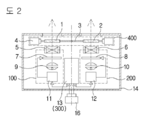
본 발명은 상기 목적을 달성하기 위하여 도 2 및 도 3과 같이 제1영상판(7)과 제1투사렌즈(5)를 좌우방향 중 일방에 배치하고 2 and 3, the
제2영상판(8)과 제2투사렌즈(6)를 좌우방향 중 타방에 배치하되The
상기 제1투사렌즈(5)와 제2투사렌즈(6) 전면에 좌우로 이동하는 수단과 결합한 좌편광판(1)과 우편광판(2)구조와 A
좌우 양방향에서 사각(斜角)으로 투사하는 상기 제1영상판(7)의 영상과 제2영상판(8)의 왜곡된 영상을 보정하여 하나의 영상으로 합치하는 영상컨트롤(300) 구조를 하나의 시스템으로 구성하고 A structure of an
상기 좌, 우편광판(1, 2)의 이동수단을 회전하는 회전축(3)에 의해 좌, 우로 이동하게 구성하며 제1, 제2영상판(7, 8)의 영상을 각각 보정회로(13)에 입력하여 좌, 우 영상 왜곡을 보정하여 하나의 영상으로 조정하는 영상컨트롤(300) 구조를 포함하고 The moving means of the left and right polarizing
상기 시스템 구조를 하나의 시스템으로 구성하기 위하여 In order to construct the system structure into one system
제 1, 2 영상판 구조(7, 8)와 좌, 우 편광판 이동 구조(400)를 좌, 우로 배치하되, 하나의 케이스(14) 내부에 구성한다.The first and second
상기와 같은 본 발명은 하나의 프로젝터 구조에서 좌, 우 편광판을 좌우로 이동하여 2D영상과 셔터 없는 일반 편광안경으로 시청할 수 있는 3D영상을 하나의 시스템에서 선택적으로 겸용 투사하고, In the present invention as described above, the left and right polarizing plates are shifted right and left in one projector structure to selectively project 3D images, which can be viewed with a 2D image and general polarizing glasses without a shutter, in one system,
광원 램프의 광도 증가와 광도증가에 따른 냉각구조 기능 확대 없이 Without increasing the cooling structure due to the increase of light intensity and the increase of light intensity of the light source lamp
2D영상은 해상도와 밝기가 2배 이상 높아지는 고해상도의 영상을 시연하여 밝은 실내에서 2D영화는 물론 스포츠중계 시청 등이 가능하며, 2D images can be displayed in high-resolution images with resolution and brightness of more than two times higher than those of 2D movies,
3D영상은 편광안경을 통해 입체영상을 시청하게 하여 종래 셔터안경 및 편광 모듈레이터를 통해 편광된 영상 대비 8배 이상의 획기적 밝기와 선명도를 얻을 수 있다. The 3D image allows stereoscopic images to be viewed through the polarizing glasses, and it is possible to obtain epoch-making brightness and sharpness of 8 times or more as compared with the polarized image through the conventional shutter glasses and the polarization modulator.
도 1은 본 발명의 외형 구성도
도 2는 본 발명의 내부 구성 설명도
도 3은 제1, 제2편광판 설명도
도 4는 제1, 제2영상판 구성 설명도
도 5는 제1, 제2편광판의 좌우 이동 설명도
도 6은 2D 영상 투사시 설명도
도 7은 3D 영상 투사시 설명도
도 8의 (a),(b),(c),(d)는 제1, 제2영상이 보정되어 하나의 영상으로 합치 시 작용 설명도Fig. 1 is an external configuration diagram of the present invention
2 is a block diagram of the internal configuration of the present invention
Fig. 3 is a schematic view of the first and second polarizer plates
Fig. 4 is a schematic diagram of the first and second image plate configurations
Fig. 5 is a diagram illustrating the left and right movement of the first and second polarizing plates
6 is an explanatory diagram when a 2D image is projected
Fig. 7 is an explanatory diagram
8 (a), 8 (b), 8 (c) and 8 (d) are diagrams for explaining how the first and second images are corrected,
도 1, 도 2와 같이 하나의 케이스(14) 내부 좌우방향에 제1, 제2의 투사광학시스템(100, 200)을 각 구비한다. As shown in FIGS. 1 and 2, the first and second projection
상기 제1, 제2투사광학시스템(100, 200) 사이에 영상컨트롤시스템(300)을 구비하고 상기 제1, 제2투사광학시스템(100, 200) 전면에 편광판이동구조(400)를 구성한다.
A polarizing
상기 제1, 제2투사광학시스템(100, 200)의 구성은 도 2와 같이 좌우 대칭구조로 구성한다.
The configuration of the first and second projection
제1투사광학시스템(100) 구조는 케이스(14) 내부 좌우측 중 일방에 구성하되, 그 내부에는 후면부위부터 램프와 집광렌즈 등의 집광구조로 구성되는 제1광원(9)을, 제1광원(9) 전면에 공지된 LCD 또는 DLP와 같은 영상 칩으로 구성한 제1영상판(7)을, 제1영상판(7) 전면에 제1투사렌즈(5)를 각 구성하고 일부에 제1회로판(11)을 구성한다.
The structure of the first projection
제2투사광학시스템(200)은 상기 제1투사광학시스템(100)과 같은 논리로 좌우 대칭 위치인 타방에 구성하되, 그 내부에 상기와 같이 제2광원(10), 제2영상판(8), 제2투사렌즈(6) 순으로 구성하고 일부에 제2회로판(12)을 구성한다.
The second projection
상기 제1, 제2회로판(11, 12) 구조는 하나의 회로판 구조에 병행 구성할 수 있다. The structure of the first and
도 2와 도 4와 같이 좌, 우편광판(1, 2)의 구조는 상기 제1, 제2투사렌즈(5, 6) 전면에 구성하되, 필요에 따라 회전모터(3a)와 연계하여 좌우 수평방향으로 회전대(3)를 하방에 이동대(4)를 각 구성하고, 상기 회전대(3)와 이동대(4) 사이에 각각 좌, 우편광판(1, 2)를 구성한다.
2 and 4, the structure of the left and right polarizing
상기 제1, 제2투사광학렌즈시스템(100, 200) 일방에는 제1, 제2영상판(7, 8)의 키스톤 현상과 같은 영상왜곡현상을 보정하는 영상컨트롤시스템(300)으로 구성한다.
One of the first and second projection
이와 같은 영상컨트롤시스템(300)은 영상 입력 단자(16)에 의해 입력되는 비디오 영상을 10Bits 이상의 비디오 프로세싱 시스템을 통해 pc 없이 osd나 IR 리모컨으로 스크린(15)에 투사된 영상을 보면서 픽셀단위로 4 코너와 모서리 위치 조정을 통해 왜곡된 영상의 상하좌우를 보정시키는 키스톤 보정 장치로서, 그 구조가 독립된 장치 또는 회로 일부에 구성하는 키스톤 보정회로로 공지되어 있으며. 상기 제1, 제2회로판 구조에 병행 구성할 수 있다. In the
상기와 같은 본 발명의 구성요소는 도 1과 같이 하나의 케이스(14) 내부에 고정 조립하여 구성요소의 기능안정을 향상시키고 설치이동을 용이하게 할 수 있다.
The components of the present invention as described above can be fixedly assembled into one
도 3과 같이 좌, 우편광판(1, 2)의 구조는 편광방향을 각각 좌, 우 반대방향으로 구성하되, 사용될 편광안경의 좌, 우 편광방향과 동일한 방향으로 구성한다.
As shown in Fig. 3, the structure of the left and right polarizing
회전대(3)의 구조는 나사모양으로 형성되어 회전대(3)가 회전모터(3a) 또는 수동방법에 의해 회전대(3)의 회전에 따라 좌, 우편광판(1, 2)이 이동대(4)를 타고 좌, 우 양방향 또는 좌,우 일방향으로 이동할 수 있도록 구성한다
The structure of the
즉 회전대(3)의 나사모양을 회전대(3)의 중심을 기준으로 좌,우 양방향으로 구성하여 That is, the screw shape of the
회전대(3)가 회전할 시 좌,우 편광판()이 가운데로 좌,우편광판(1, 2)이 이동하고 반대로 회전할 때는 양방향으로 이동 한다The left and
회전대(3)의 나사모양을 일방향으로 구성하여 회전시는 좌,우편광판(1, 2)이 일방향으로 동시에 이동되고 회전대(3)가 역방향으로 회전 시는 일방향으로 동시 복귀한다 The
3D영상 투사시는 좌,우편광판(1, 2)이 제1, 제2투사렌즈(5, 6) 앞으로 이동하고, 2D영상 투사시는 좌, 우편광판(1, 2)이 제1, 제2투사렌즈(5, 6)의 외곽으로 이동하여 제1, 제2투사렌즈(5, 6)를 노출하게 한다. When the 3D image is projected, the left and
즉, 회전대(3)의 회전에 의해 좌, 우편광판(1, 2)이 좌우로 이동하여 3D영상 투사 시는 좌, 우 투사렌즈(5, 6) 전면에 좌, 우편광판(1, 2)을 배치하고, 2D영상 투사 시에는 상기 좌, 우편광판(1, 2)을 좌우로 이동시켜 제1, 제2투사렌즈(5, 6)를 노출시킴으로서 2D영상을 투사할 수 있는 것이다.
That is, the left and
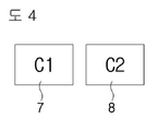
도 3과 같이 3D영상 투사 시에는 제1, 제2영상판(7, 8)에 입체용의 좌안용 영상(L)과 우안용 영상(R)이 각각 결상되고, 도 4와 같이 2D영상 투사 시에는 제1, 제2영상판(7, 8)에 C 1, C 2와 같이 동일한 영상이 각 결상된다.
As shown in FIG. 3, when a 3D image is projected, a three-dimensional left eye image L and a right eye image R are respectively formed on the first and
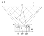
3D영상 투사 시에는 도 3과 같이 제1영상판(7)에 입체용 좌안용 영상(L)을 제2영상판(8)에 입체용 우안용 영상(R)을 각 입력하고, 도 7과 같이 제1, 제2투사렌즈(5, 6)을 통해 스크린(15)(15)에 투사할 때 회전대(3)를 회전시켜 상기 제1, 제2투사렌즈(5, 6)의 각 전면에 좌 편광판(1)과 우편광판(2)이 각 위치하게 이동한다,
The stereoscopic left eye image L is inputted to the
도 8의 (b)와 같이 영상컨트롤시스템(300)에 의해 좌, 우가 왜곡된 입체용 좌, 우안용 영상(L, R)을 도 8의 (C)와 같이 보정한 후 도 7과 같이 스크린(15)에 투사하고 이를 편광안경(17)을 통해 입체영상으로 시청하게 된다. As shown in FIG. 8 (b), the left and right stereoscopic left and right images L and R distorted left and right by the
이러한 본 발명의 구조는 도 6과 같이 2D영상으로 투사할 시에는 제1, 제2영상판(7, 8)에서 도 4와 같이 동일한 영상을 하나의 스크린(15)에 동시에 투사한다.
6, the same image is simultaneously projected on one
이 경우 도 8의 (a), (b)와 같이 제1, 제2영상판(7, 8)의 좌, 우 2D영상 (C 1, C 2)은 제1투사렌즈(5)에서 사각(斜角)으로 투사된 좌영상에서는 좌에서 우로 사다리꼴 형상의 이른바 키스톤 현상이 발생하고 제2투사렌즈(6)에서 사각으로 투사된 우영상에서는 우에서 좌로 사다리꼴 형상의 키스톤 현상이 발생한다. In this case, as shown in FIGS. 8A and 8B, the left and right
이와 같은 상기 좌, 우 2D영상(C 1, C 2)은 도 8의 (c)와 같이 좌우 왜곡된 키스톤 영상이 겹치게 되는바, 이를 도8의 (d)와 같이 영상컨트롤시스템(300)에 의해 보정하여 좌, 우 영상을 일치시킨다. 8 (c), left and right distorted keystone images are superimposed on the left and right
따라서 이러한 본 발명은 2D영상 투사시 도 6과 같이 좌, 우편광판(1, 2)을 좌우로 이동하여 제1, 제2투사렌즈(5, 6)를 좌, 우편광판(1, 2)으로부터 노출시킨 뒤 도 2 와같이 영상입력단자(16)를 통해 입력되는 두 개의 2D영상(C1, C2)을 도4와 같이 제1, 제2영상판(7, 8)에 입력한다. Therefore, when the 2D image is projected, the first and
상기 입력된 영상은 영상컨트롤장치(300)에 의해 도 8의 (c)와 같이 좌우 왜곡된 영상을 도 8의 (d)와 같은 보정된 영상으로 보정하여, 도 8의 (e)와 도 6과 같이 두 개의 2D영상(C 1, C 2)이 하나의 영상으로 스크린(15)(15)에서 중첩하게 된다. The input image is corrected by the
이와 같이 중첩된 상기 영상은 도 8의 (e)와 같이 종래 영상 대비 두 개의 광원 즉, 제 1, 제2광원(9, 10)에서 투사되는 영상이므로 밝기가 2배가 되고 도 8의 (e)와 같이 두 개의 영상이 겹쳐져 영상을 두 번 스캐닝 해주게 되므로 더블스케닝 효과로 해상도가 2배로 높아진다. 8 (e), the brightness is doubled because the image is projected from the two light sources, that is, the first and second
일반 영상은 통상 밝기가 높아지면 콘트라스트가 저하된다. Normal images usually have low contrast as the brightness increases.
그러나 본 발명의 영상은 각기 제1, 제2회로판(11, 12)에 의해 명암 대비(contrast) 비율이 이미 조정된 영상을 또 한번 중복하는 이른바 더블 스캐닝 효과가 있으므로 밝기가 2배 높아지더라도 명암대비 비율은 그대로 유지되므로 결과적으로 선명도가 2배로 높아지는 효과를 갖게 된다. However, since the image of the present invention has a so-called double scanning effect in which an image in which the contrast ratio is already adjusted by the first and
따라서 종래 프로젝터가 광원의 냉각시스템 구성의 한계와 램프의 밝기 한계로 선명도 증대에 한계가 있었으나 본 발명은 밝기를 2배 이상 증대할 수 있는 것이다. Therefore, although the conventional projector has a limitation in the configuration of the cooling system of the light source and the brightness limit of the lamp, the brightness of the present invention can be doubled.
3D영상에 있어서 종래 극장용 3D프로젝터는 하나의 투사렌즈에 순차적으로 좌, 우 영상을 분할하므로 밝기가 50%로 떨어지고 이를 다시 편광 모듈레이터를 통해 편광하여 투사하게 되는데 이때 모듈레이터의 일반적인 투광률은 8%로서 10% 미만인 것은 공지되어 있다. 이를 투과율 40-50%의 편광안경으로 시청하게 되므로 전체 밝기가 1/40로 떨어져 2.5%의 매우 어두운 영상으로 시청하게 된다. In 3D images, the conventional 3D projector divides the left and right images one by one into a single projection lens, so the brightness drops to 50% and then it is projected by polarizing it through the polarization modulator. In this case, the general light transmittance of the modulator is 8% Is less than 10%. It is viewed with polarized glasses having a transmittance of 40-50%, so that the entire brightness is reduced to 1/40, and a very dark image of 2.5% is viewed.
본 발명의 경우는 두 개의 좌,우 광원에서 투사하므로 밝기가 2배 증대되고 이를 좌, 우 편광판(1, 2)에서 투과율이 1/2로 떨어지고 편광안경에서 1/2로 떨어진다 해도 결과적으로 50%의 밝기가 유지된다. In the case of the present invention, since the brightness is doubled because of the projection from the two left and right light sources, and the transmittance of the left and
즉, 본 발명이 갖는 구조의 효과는 3D영상에 있어서 종래 프로젝터의 3D 영상 밝기 2.5%대비 50%의 밝기를 유지하므로 10배 - 20배 이상의 선명도와 밝기 증대 효과를 갖게 된다. That is, the effect of the structure of the present invention is to maintain a brightness of 50% compared to 2.5% of the 3D image brightness of a conventional projector in a 3D image, so that it has a sharpness and brightness enhancement of 10 times to 20 times or more.
또한, 본 발명의 구조는 제1,제2편광판(1, 2)의 좌우 이동에 따라 2D, 3D가 간단히 변환되고, 종래 2D/3D 프로젝터와 대비하여 2D는 선명도가 유지된 상태에서 2배의 밝기와 선명도의 영상을, 3D는 10-20배의 고선명의 입체영상을 투사할 수 있다. In the structure of the present invention, 2D and 3D are simply converted according to the left and right movement of the first and
따라서 이와 같은 본 발명은 편광판의 좌우 이동 여부에 따라 2D영상 시청 시는 2배의 밝기, 2배의 선명도로 영상을 투사하므로 밝은 장소에서도 선명한 2D영상으로 스포츠 영상이나 가수의 라이브콘서트와 같은 다양한 영상 감상이 가능하며, 3D영상 시청 시는 종래 대비 10배-20배 이상의 밝기와 선명도로 3D영상 감상이 가능하다. Therefore, according to the present invention, since the image is projected at twice the brightness and twice the sharpness at the time of viewing the 2D image depending on whether the polarizer is moved left or right, a clear 2D image can be displayed in a bright place, It is possible to enjoy 3D images with brightness and sharpness more than 10 times to 20 times higher than conventional.
1. 좌편광판 2. 우편광판 3. 회전대 3a. 회전모터
4. 이동대 5. 제 1 투사렌즈 6. 제 2 투사렌즈 7. 제 1 영상판
8. 제 2 영상판 9. 제 1 광원 10. 제 2 광원 11. 제 1 영상회로판
12. 제 2 영상회로판 13. 좌, 우 보정회로 14. 케이스 15. 스크린(15)
16. 영상 입력단자
100. 제 1 투사광학시스템 200. 제 2 투사광학시스템
300. 영상 컨트롤 시스템 400. 편광판 이동 구조1.
4. Moving stand 5.
8.
12.
16. Video input terminal
100. First projection
300.
Claims (4)
제1영상판(7)과 제1투사렌즈(5)를 좌측에 배치하고
제2영상판(8)과 제2투사렌즈(6)를 우측에 배치하되
상기 제1투사렌즈(5)와 제2투사렌즈(6) 전면에
좌우로 이동하는 이동수단과 결합한 좌편광판(1)과 우편광판(2):을 각 구성하고
상기 좌, 우에서 사각(斜角)으로 투사하는 제1영상판(7)의 영상과 제2영상판(8)의 왜곡된 영상을 보정하여 하나의 영상으로 합치하는 영상컨트롤(300)구조를 포함하여
하나의 시스템으로 구성함으로써 밝기와 해상도를 2배 이상 증대하는 것을
특징으로 하는 고선명 2D/3D 겸용 프로젝터 시스템
In a high-definition 2D / 3D combined projector system
The first image plate 7 and the first projection lens 5 are disposed on the left side
The second image plate 8 and the second projection lens 6 are disposed on the right side
On the front face of the first projection lens 5 and the second projection lens 6
A left polarizer plate 1 and a right polarizer plate 2 combined with moving means moving left and right are constituted respectively
A structure of an image control 300 for correcting the distorted image of the first image plate 7 and the distorted image of the second image plate 8 projecting from the left and right at an oblique angle is combined into one image, including
It is possible to increase the brightness and resolution more than twice by constructing one system
High-definition 2D / 3D combined projector system
좌, 우편광판(1, 2)의 이동수단을
회전하는 회전축(3)에 의해 좌우로 이동하는
편광판 이동구조(400)로 구성하는 것을 특징으로 하는
고선명 2D/3D 겸용 프로젝터 시스템The method of claim 1, wherein
The moving means of the left and right polarizing plates 1 and 2
And is moved left and right by the rotating rotary shaft 3
And a polarizing plate moving structure (400).
High-definition 2D / 3D combined projector system
제1, 제2영상판(7, 8)의 두 개의 영상을
좌, 우 사각(斜角)에서 각각 투사함으로 해서 발생하는 영상 왜곡을 보정하여 하나의 영상으로 조정하는 영상컨트롤(300) 구조를 포함하는 것을 특징으로 하는 고선명 2D/3D 겸용 프로젝터 시스템
The method of claim 1, wherein
Two images of the first and second image plates 7 and 8
And an image control unit (300) for correcting the image distortion caused by projecting the image at the left and right oblique angles, respectively, into a single image. The high definition 2D / 3D combined projector system
하나의 시스템으로 구성하기 위하여 제 1항의 시스템 구조를
하나의 케이스(14)에 구성한 것을 특징으로 하는 고선명 2D/3D 겸용 프로젝터 시스템
The method of claim 1, wherein
To construct one system, the system structure of claim 1
And a single high-definition 2D / 3D projector system
Priority Applications (1)
| Application Number | Priority Date | Filing Date | Title |
|---|---|---|---|
| KR1020160048709A KR102457334B1 (en) | 2016-04-21 | 2016-04-21 | High-definition 2D/3D Combination Projector Systemm |
Applications Claiming Priority (1)
| Application Number | Priority Date | Filing Date | Title |
|---|---|---|---|
| KR1020160048709A KR102457334B1 (en) | 2016-04-21 | 2016-04-21 | High-definition 2D/3D Combination Projector Systemm |
Publications (2)
| Publication Number | Publication Date |
|---|---|
| KR20170120351A true KR20170120351A (en) | 2017-10-31 |
| KR102457334B1 KR102457334B1 (en) | 2022-10-20 |
Family
ID=60301605
Family Applications (1)
| Application Number | Title | Priority Date | Filing Date |
|---|---|---|---|
| KR1020160048709A KR102457334B1 (en) | 2016-04-21 | 2016-04-21 | High-definition 2D/3D Combination Projector Systemm |
Country Status (1)
| Country | Link |
|---|---|
| KR (1) | KR102457334B1 (en) |
Citations (6)
| Publication number | Priority date | Publication date | Assignee | Title |
|---|---|---|---|---|
| KR100616556B1 (en) * | 2004-06-12 | 2006-08-28 | 김은수 | Polarized stereoscopic display device and method without loss |
| KR20110044860A (en) | 2008-08-07 | 2011-05-02 | 세키스이가가쿠 고교가부시키가이샤 | Insulation Sheets and Laminated Structures |
| KR20120002046U (en) | 2010-09-10 | 2012-03-20 | (주)메가이엔지 | Cable tie which is drawn horizontally and comprises means for fixing tail |
| KR20120126801A (en) * | 2011-05-13 | 2012-11-21 | 최해용 | 2D-3D converting projector |
| KR20130008911A (en) * | 2011-07-13 | 2013-01-23 | 엘지디스플레이 주식회사 | Stereoscopic image display device and driving method thereof |
| JP2013182194A (en) * | 2012-03-02 | 2013-09-12 | Seiko Epson Corp | Polarization control device, projector system, polarization control method, and image control method |
-
2016
- 2016-04-21 KR KR1020160048709A patent/KR102457334B1/en active IP Right Grant
Patent Citations (6)
| Publication number | Priority date | Publication date | Assignee | Title |
|---|---|---|---|---|
| KR100616556B1 (en) * | 2004-06-12 | 2006-08-28 | 김은수 | Polarized stereoscopic display device and method without loss |
| KR20110044860A (en) | 2008-08-07 | 2011-05-02 | 세키스이가가쿠 고교가부시키가이샤 | Insulation Sheets and Laminated Structures |
| KR20120002046U (en) | 2010-09-10 | 2012-03-20 | (주)메가이엔지 | Cable tie which is drawn horizontally and comprises means for fixing tail |
| KR20120126801A (en) * | 2011-05-13 | 2012-11-21 | 최해용 | 2D-3D converting projector |
| KR20130008911A (en) * | 2011-07-13 | 2013-01-23 | 엘지디스플레이 주식회사 | Stereoscopic image display device and driving method thereof |
| JP2013182194A (en) * | 2012-03-02 | 2013-09-12 | Seiko Epson Corp | Polarization control device, projector system, polarization control method, and image control method |
Also Published As
| Publication number | Publication date |
|---|---|
| KR102457334B1 (en) | 2022-10-20 |
Similar Documents
| Publication | Publication Date | Title |
|---|---|---|
| US8289380B2 (en) | Polarized stereoscopic display device and method | |
| US20190196214A1 (en) | Polarization conversion system and method for projecting polarization encoded imagery | |
| US8388138B1 (en) | Projection display systems | |
| RU2483469C2 (en) | Stereoscopic system for forming and displaying images | |
| US20050237487A1 (en) | Color wheel assembly for stereoscopic imaging | |
| US20100079728A1 (en) | Stereoscopic image projecting system using circularly polarized filter module | |
| KR101174075B1 (en) | Stereoscopic Image Display System, and Stereoscopic Image Player and Stereoscopic Image Player For the Same | |
| KR20120050982A (en) | Stereoscopic projection system employing spatial multiplexing at an intermediate image plane | |
| US10663851B2 (en) | Stereoscopic image display device | |
| KR20120057916A (en) | 3d converting magnification of projection optical system | |
| WO2006038744A1 (en) | Digital image projection system and method for 3-dimensional stereoscopic display | |
| KR100845584B1 (en) | Circularly polarized filter, stereoscopic image projector ststem, apparatus for stereoscopic image projecting ststem, and stereoscopic image projecting ststem using the same | |
| JP2009539138A (en) | Structure of stereo optical engine for projection | |
| Kim et al. | A new liquid crystal display-based polarized stereoscopic projection method with improved light efficiency | |
| JP2012120169A (en) | Test pattern for stereoscopic image extinction evaluation, stereoscopic image crosstalk evaluation method and computer storage device | |
| JPS62160437A (en) | Superposing method for projection image | |
| CN101943852A (en) | Optical three-dimensional projection device, system and three-dimensional projection method | |
| KR20070035397A (en) | 3D monitor system For Single channel | |
| KR102457334B1 (en) | High-definition 2D/3D Combination Projector Systemm | |
| KR20170003757U (en) | High-definition 2D/3D Combination Projector Systemm | |
| WO2011003234A1 (en) | Optical stereo projection device, system and method | |
| KR20110105830A (en) | Single-sensor juxtaposing type stereo-picture shooting method | |
| KR100909275B1 (en) | Stereoscopic projection system and device for stereoscopic projection | |
| KR101060159B1 (en) | 3D image output method using LCC type projector and apparatus therefor | |
| KR20060091543A (en) | Polarized stereoscopic display device without loss |
Legal Events
| Date | Code | Title | Description |
|---|---|---|---|
| A201 | Request for examination | ||
| E701 | Decision to grant or registration of patent right | ||
| GRNT | Written decision to grant |