KR20170114043A - Particular Matter Sensor - Google Patents
Particular Matter Sensor Download PDFInfo
- Publication number
- KR20170114043A KR20170114043A KR1020160039712A KR20160039712A KR20170114043A KR 20170114043 A KR20170114043 A KR 20170114043A KR 1020160039712 A KR1020160039712 A KR 1020160039712A KR 20160039712 A KR20160039712 A KR 20160039712A KR 20170114043 A KR20170114043 A KR 20170114043A
- Authority
- KR
- South Korea
- Prior art keywords
- electrode
- capacitance
- unit
- particulate matter
- insulating substrate
- Prior art date
Links
Images


Classifications
-
- G—PHYSICS
- G01—MEASURING; TESTING
- G01N—INVESTIGATING OR ANALYSING MATERIALS BY DETERMINING THEIR CHEMICAL OR PHYSICAL PROPERTIES
- G01N15/00—Investigating characteristics of particles; Investigating permeability, pore-volume, or surface-area of porous materials
- G01N15/10—Investigating individual particles
- G01N15/1031—Investigating individual particles by measuring electrical or magnetic effects thereof, e.g. conductivity or capacity
-
- G—PHYSICS
- G01—MEASURING; TESTING
- G01N—INVESTIGATING OR ANALYSING MATERIALS BY DETERMINING THEIR CHEMICAL OR PHYSICAL PROPERTIES
- G01N1/00—Sampling; Preparing specimens for investigation
- G01N1/02—Devices for withdrawing samples
- G01N1/22—Devices for withdrawing samples in the gaseous state
- G01N1/2247—Sampling from a flowing stream of gas
- G01N1/2252—Sampling from a flowing stream of gas in a vehicle exhaust
-
- G—PHYSICS
- G01—MEASURING; TESTING
- G01N—INVESTIGATING OR ANALYSING MATERIALS BY DETERMINING THEIR CHEMICAL OR PHYSICAL PROPERTIES
- G01N25/00—Investigating or analyzing materials by the use of thermal means
- G01N25/20—Investigating or analyzing materials by the use of thermal means by investigating the development of heat, i.e. calorimetry, e.g. by measuring specific heat, by measuring thermal conductivity
- G01N25/22—Investigating or analyzing materials by the use of thermal means by investigating the development of heat, i.e. calorimetry, e.g. by measuring specific heat, by measuring thermal conductivity on combustion or catalytic oxidation, e.g. of components of gas mixtures
- G01N25/28—Investigating or analyzing materials by the use of thermal means by investigating the development of heat, i.e. calorimetry, e.g. by measuring specific heat, by measuring thermal conductivity on combustion or catalytic oxidation, e.g. of components of gas mixtures the rise in temperature of the gases resulting from combustion being measured directly
- G01N25/30—Investigating or analyzing materials by the use of thermal means by investigating the development of heat, i.e. calorimetry, e.g. by measuring specific heat, by measuring thermal conductivity on combustion or catalytic oxidation, e.g. of components of gas mixtures the rise in temperature of the gases resulting from combustion being measured directly using electric temperature-responsive elements
- G01N25/32—Investigating or analyzing materials by the use of thermal means by investigating the development of heat, i.e. calorimetry, e.g. by measuring specific heat, by measuring thermal conductivity on combustion or catalytic oxidation, e.g. of components of gas mixtures the rise in temperature of the gases resulting from combustion being measured directly using electric temperature-responsive elements using thermoelectric elements
-
- G—PHYSICS
- G01—MEASURING; TESTING
- G01N—INVESTIGATING OR ANALYSING MATERIALS BY DETERMINING THEIR CHEMICAL OR PHYSICAL PROPERTIES
- G01N27/00—Investigating or analysing materials by the use of electric, electrochemical, or magnetic means
- G01N27/26—Investigating or analysing materials by the use of electric, electrochemical, or magnetic means by investigating electrochemical variables; by using electrolysis or electrophoresis
- G01N27/28—Electrolytic cell components
- G01N27/30—Electrodes, e.g. test electrodes; Half-cells
- G01N27/305—Electrodes, e.g. test electrodes; Half-cells optically transparent or photoresponsive electrodes
Landscapes
- Chemical & Material Sciences (AREA)
- Life Sciences & Earth Sciences (AREA)
- Health & Medical Sciences (AREA)
- Pathology (AREA)
- General Physics & Mathematics (AREA)
- Physics & Mathematics (AREA)
- Immunology (AREA)
- Analytical Chemistry (AREA)
- Biochemistry (AREA)
- General Health & Medical Sciences (AREA)
- Engineering & Computer Science (AREA)
- Molecular Biology (AREA)
- Chemical Kinetics & Catalysis (AREA)
- Combustion & Propulsion (AREA)
- Biomedical Technology (AREA)
- Electrochemistry (AREA)
- Dispersion Chemistry (AREA)
- Investigating Or Analyzing Materials By The Use Of Electric Means (AREA)
Abstract
입자상 물질 센서가 제공된다. 본 발명의 일 실시예에 따른 입자상 물질센서는 절연기판; 상기 절연기판의 일면에 형성되며, 입자상 물질이 퇴적되는 감응부와 정전용량을 측정하기 위한 용량부를 갖추어 서로 전기적으로 연결되지 않은 복수 개의 이격전극을 포함하는 제1전극부; 상기 절연기판의 내부에 배치되며, 상기 제1전극부와의 정전용량을 측정할 수 있도록 상기 용량부와 대응되는 영역에 이격배치되는 제2전극부; 및 상기 절연기판의 내부에 배치되어 상기 감응부를 가열하는 히터부;를 포함하고, 상기 감응부 및 용량부는 소정의 길이를 갖는 리드부를 매개로 서로 이격배치된다.A particulate matter sensor is provided. A particulate matter sensor according to an embodiment of the present invention includes an insulating substrate; A first electrode unit formed on one surface of the insulating substrate and including a plurality of spaced apart electrodes electrically connected to each other, the plurality of spaced apart electrodes being provided with a sensing unit for accumulating particulate matter and a capacitance unit for measuring capacitance; A second electrode part disposed inside the insulating substrate and spaced apart from a region corresponding to the capacitance part so as to measure a capacitance with the first electrode part; And a heater disposed inside the insulating substrate and heating the susceptor, wherein the susceptor and the capacitor are spaced apart from each other via a lead having a predetermined length.
Description
본 발명은 입자상 물질 센서에 관한 것으로, 더욱 상세하게는 유전율의 급격한 변화가 발생하는 고온의 환경에서도 일정한 정전용량을 구현할 수 있는 입자상 물질 센서에 관한 것이다.The present invention relates to a particulate matter sensor, and more particularly, to a particulate matter sensor capable of realizing a constant electrostatic capacity even in a high temperature environment where a sudden change in permittivity occurs.
일반적으로, 배기 규제가 한층 강화됨에 따라 배기 가스를 정화하는 후처리 장치에 대한 관심이 높아지고 있다. 특히, 디젤 자동차에 대한 입자상 물질(Particulate Matter; PM)에 대한 규제가 더욱 엄격해지고 있다.Generally, there is a growing interest in a post-treatment apparatus for purifying exhaust gas as the exhaust regulation is further strengthened. Particularly, regulations on Particulate Matter (PM) for diesel vehicles are becoming more stringent.
그 일환으로, 입자상 물질을 저감시키는 가장 효율적이고 실용화에 접근되는 기술은 매연 여과장치를 이용한 배기가스 저감장치이다.As a result, the most efficient and practical approach to reducing particulate matter is an exhaust gas reduction device using a soot filter.
한편, 배기가스 저감장치의 고장 여부를 진단하기 위해서는 DPF필터 후단에 입자상 물질 센서(PM센서)가 장착되며, 이러한 입자상 물질 센서(PM)는 저항방식과 전정용량 방식이 있다.Meanwhile, a particulate matter sensor (PM sensor) is mounted on the downstream side of the DPF filter in order to diagnose whether the exhaust gas abatement apparatus is faulty or not.
위의 방식 중, 정전용량 방식은 절연기판의 표면 상에 나란하게 배치되는 복수 개의 외부전극과, 복수 개의 외부전극과 상/하 방향으로 배치되는 복수 개의 내부전극으로 구성되며, 외부전극들 사이에 퇴적하는 입자상 물질의 면적 및 외부전극과 내부전극 사이의 거리를 이용하여 외부전극과 내부전극 사이의 정전용량을 측정함으로써, 배기가스 미립자 필터를 통과하여 하류 측으로 빠져나가는 입자상 물질을 용이하게 검출할 수 있다.In the above-described method, the electrostatic capacity type is constituted by a plurality of external electrodes arranged in parallel on the surface of the insulating substrate, a plurality of internal electrodes arranged in the up / down direction with a plurality of external electrodes, By measuring the capacitance between the external electrode and the internal electrode using the area of the particulate matter deposited and the distance between the external electrode and the internal electrode, it is possible to easily detect the particulate matter passing through the exhaust gas particulate filter and escaping to the downstream side have.
이때, 복수 개의 외부전극은 입자상 물질이 퇴적되는 감응부와 내부전극과의 정전용량을 측정하기 위한 용량부가 각각 구비되며, 감응부와 용량부는 서로 인접한 위치에 형성된다. 이에 따라, 입자상 물질이 퇴적되는 감응부가 고온의 배기가스에 노출되는 경우 감응부와 인접한 위치에 형성된 용량부 역시 배기가스에서 전달되는 온도의 영향을 받게 된다.At this time, the plurality of external electrodes are each provided with capacitive portions for measuring the electrostatic capacitance between the sensitive portion and the internal electrodes where the particulate matter is deposited, and the sensing portion and the capacitive portion are formed at positions adjacent to each other. Accordingly, when the sensitive portion to which the particulate matter is deposited is exposed to the high-temperature exhaust gas, the capacity portion formed at the position adjacent to the sensitive portion is also affected by the temperature transferred from the exhaust gas.
한편, 절연기판의 경우 재료의 특성상 고온의 환경에서는 유전율의 급격한 변화가 발생한다.On the other hand, in the case of an insulating substrate, the dielectric constant suddenly changes in a high temperature environment due to the characteristics of the material.
일례로, 절연기판이 알루미나로 이루어진 경우 600℃ 부근에서 급격한 유전율의 변화가 발생한다. For example, when the insulating substrate is made of alumina, a sudden change in the dielectric constant occurs at about 600 ° C.
이에 따라, 감응부가 600℃ 이상의 고온의 환경에 노출되는 경우 감응부와 인접한 위치에 형성된 용량부 역시 고온의 영향을 받게 되므로, 급격한 유전율의 변화에 의해 외부전극과 내부전극 사이에 일정한 정전용량을 구현하기 어려운 문제점이 있다.Accordingly, when the sensitive part is exposed to a high temperature environment of 600 ° C or more, the capacitive part formed adjacent to the sensitive part is also affected by the high temperature, so that a constant capacitance is formed between the external electrode and the internal electrode There is a problem that is difficult to do.
즉, 감응부와 용량부가 서로 인접하게 형성되는 경우 소정 온도 이상의 고온의 환경에서는 일정한 정전용량을 측정할 수 없어 사용상에 제약이 발생한다.That is, when the sensitive part and the capacitive part are formed adjacent to each other, a constant capacitance can not be measured in a high temperature environment of a predetermined temperature or higher, resulting in restrictions on the use.
한편, 입자상 물질 센서는 재사용을 위한 리플래쉬 과정에서 입자상 물질센서 상에 퇴적된 입자상 물질을 제거하기 위하여 히터부를 통해 열을 가하게 된다. 이로 인해, 히터부에서 가해지는 열에 의해 절연기판의 온도가 상승된다. 이때, 절연기판의 온도는 통상적으로 650℃이상 1200℃까지 상승될 수 있다.On the other hand, the particulate matter sensor is heated through the heater unit to remove the particulate matter deposited on the particulate matter sensor during the re-flashing process for reuse. As a result, the temperature of the insulating substrate is raised by the heat applied by the heater unit. At this time, the temperature of the insulating substrate may be raised from 650 ° C to 1200 ° C.
이에 따라, 히터부의 열을 이용해 퇴적된 입자상 물질을 제거한 후 절연기판의 온도가 소정의 온도 이하로 떨어질 때까지 사용하기 어려운 문제점이 있다.Accordingly, there is a problem that after the particulate matter deposited by using the heat of the heater is removed, it is difficult to use until the temperature of the insulating substrate falls below a predetermined temperature.
본 발명은 상기와 같은 점을 감안하여 안출한 것으로, 절연기판의 유전율이 급격하게 변화되는 고온의 환경에서도 일정한 정전용량을 구현할 수 있는 입자상 물질 센서를 제공하는데 그 목적이 있다.SUMMARY OF THE INVENTION It is an object of the present invention to provide a particulate matter sensor capable of realizing a constant capacitance even in a high temperature environment in which dielectric constant of an insulating substrate is abruptly changed.
또한, 본 발명은 재사용을 위한 리플래쉬 공정 후 대기시간 없이 곧바로 사용할 수 있는 입자상 물질 센서를 제공하는데 다른 목적이 있다.It is another object of the present invention to provide a particulate matter sensor which can be used immediately after a re-flash process for reuse without waiting time.
상술한 과제를 해결하기 위하여 본 발명은 절연기판; 상기 절연기판의 일면에 형성되며, 입자상 물질이 퇴적되는 감응부와 정전용량을 측정하기 위한 용량부를 갖추어 서로 전기적으로 연결되지 않은 복수 개의 이격전극을 포함하는 제1전극부; 상기 절연기판의 내부에 배치되며, 상기 제1전극부와의 정전용량을 측정할 수 있도록 상기 용량부와 대응되는 영역에 이격배치되는 제2전극부; 및 상기 절연기판의 내부에 배치되어 상기 감응부를 가열하는 히터부;를 포함하고, 상기 감응부 및 용량부는 소정의 길이를 갖는 리드부를 매개로 서로 이격배치되는 입자상 물질 센서를 제공한다.According to an aspect of the present invention, A first electrode unit formed on one surface of the insulating substrate and including a plurality of spaced apart electrodes electrically connected to each other, the plurality of spaced apart electrodes being provided with a sensing unit for accumulating particulate matter and a capacitance unit for measuring capacitance; A second electrode part disposed inside the insulating substrate and spaced apart from a region corresponding to the capacitance part so as to measure a capacitance with the first electrode part; And a heater disposed inside the insulating substrate and heating the susceptor, And the sensing part and the capacitance part are disposed apart from each other via a lead part having a predetermined length.
또한, 상기 리드부의 길이는 상기 감응부의 길이와 동일하거나 더 긴 길이를 갖도록 구비될 수 있다.The length of the lead portion may be equal to or longer than the length of the sensing portion.
또한, 상기 제1전극부는 상기 복수 개의 이격전극을 둘러싸도록 배치되는 테두리전극 및 상기 테두리전극으로부터 내측으로 연장되는 복수 개의 연장전극을 포함하며, 상기 이격전극은 서로 이웃하는 한 쌍의 연장전극 사이 또는 서로 이웃하는 연장전극과 테두리전극 사이에 상기 감응부가 위치하도록 배치될 수 있다.The first electrode unit may include a rim electrode disposed to surround the plurality of spaced apart electrodes and a plurality of extended electrodes extending inward from the rim electrode, And may be disposed such that the sensitive portion is positioned between adjacent extension electrodes and the rim electrode.
또한, 상기 제2전극부는 상기 용량부와 대응되는 면적을 갖는 복수 개의 용량전극을 포함하며, 상기 복수 개의 용량전극은 서로 전기적으로 연결될 수 있다.The second electrode unit may include a plurality of capacitive electrodes having an area corresponding to the capacitive unit, and the plurality of capacitive electrodes may be electrically connected to each other.
또한, 상기 감응부의 전체면적은 상기 용량부의 전체면적보다 좁은 면적을 갖도록 구비될 수 있다.Also, The total area of the sensing part may be smaller than the entire area of the capacitor.
또한, 상기 제2전극부와 상기 히터부 사이에 배치되어 상기 히터부를 제어하는 온도 감지부를 더 포함할 수 있다.The apparatus may further include a temperature sensing unit disposed between the second electrode unit and the heater unit to control the heater unit.
또한, 상기 절연기판은 알루미나 또는 ZTA일 수 있다.Further, the insulating substrate may be alumina or ZTA.
또한, 상기 입자상 물질 센서는 하우징에 내장되어 차량의 배기가스 미립자 필터의 후단에 연결되는 배기관 측에 상기 감응부가 노출되도록 장착될 수 있다.In addition, the particulate matter sensor may be mounted in the housing so that the sensitive portion is exposed to the exhaust pipe side connected to the rear end of the exhaust gas particulate filter of the vehicle.
또한, 상기 하우징은, 상기 입자상 물질 센서가 삽입되고, 상기 배기관에 고정되는 몸체부; 및 상기 몸체부의 일측에 결합되어 상기 몸체부의 일측으로 노출되는 상기 감응부를 보호하는 보호커버;를 포함할 수 있다.The housing may further include: a body portion to which the particulate matter sensor is inserted and fixed to the exhaust pipe; And And a protective cover coupled to one side of the body part to protect the sensitive part exposed to one side of the body part.
또한, 상기 보호커버의 일측에는 상기 감응부 측으로 배기가스를 유입하기 위한 적어도 하나의 개구부가 형성될 수 있다.At least one opening may be formed on one side of the protective cover for introducing the exhaust gas into the sensing unit.
본 발명에 의하면, 입자상 물질이 퇴적되는 감응부와 정전용량을 감지하는 용량부가 리드부를 통해 소정의 간격을 두고 이격배치됨으로써, 감응부가 고온의 환경에 노출되더라도 용량부 측이 유전율의 급격한 변화가 발생하지 않는 저온을 유지할 수 있게 되므로 고온의 환경에서도 온도에 영향을 받지 않고 일정한 정전용량을 구현할 수 있다.According to the present invention, since the sensitive part in which the particulate matter is deposited and the capacitance part for sensing capacitance are spaced apart from each other at a predetermined interval, even if the sensitive part is exposed to a high temperature environment, a sudden change It is possible to maintain constant low temperature without being affected by temperature even in a high temperature environment.
또한, 감응부에 퇴적된 입자상 물질을 제거하기 위하여 히터부를 통해 감응부를 가열하더라도 일정간격 이격된 용량부 측에는 열이 가해지지 않음으로써 대기시간 없이 재사용이 가능하다.Further, even if the induction portion is heated through the heater portion to remove the particulate matter accumulated in the induction portion, heat is not applied to the capacity portion spaced apart by a predetermined distance, so that reuse is possible without waiting time.
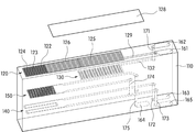
도 1은 본 발명의 일 실시예에 따른 입자상 물질 센서를 개략적으로 도시한 사시도,
도 2는 도 1에서 주요구성의 배치관계를 나타내기 위한 개략도,
도 3은 본 발명의 일 실시예에 따른 입자상 물질 센서에서 제1전극부를 도시한 평면도,
도 4 는 본 발명의 일 실시예에 따른 입자상 물질 센서에 제1전극부의 감응부에 입자상 물질이 퇴적된 상태를 도시한 도면,
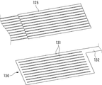
도 5는 본 발명의 일 실시예에 따른 입자상 물질 센서의 용량부와 제2전극부를 도시한 도면,
도 6은 본 발명의 일 실시예에 따른 입자상 물질 센서의 장착위치를 나타낸 개략도, 그리고,
도 7은 본 발명의 일 실시예에 따른 입자상 물질 센서가 하우징에 내장된 설치상태도를 나타낸 도면이다.1 is a perspective view schematically showing a particulate matter sensor according to an embodiment of the present invention,
Fig. 2 is a schematic view for showing a layout relationship of the main configuration in Fig. 1,
3 is a plan view showing a first electrode unit in a particulate matter sensor according to an embodiment of the present invention,
4 is a view illustrating a state where particulate matter is deposited on a sensitive portion of a first electrode portion in a particulate matter sensor according to an embodiment of the present invention;
5 is a view showing a capacitance portion and a second electrode portion of a particulate matter sensor according to an embodiment of the present invention,
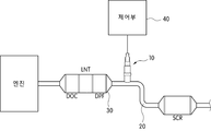
6 is a schematic view showing a mounting position of a particulate matter sensor according to an embodiment of the present invention,
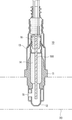
7 is a view showing an installation state in which a particulate matter sensor according to an embodiment of the present invention is incorporated in a housing.
이하, 첨부한 도면을 참고로 하여 본 발명의 실시예에 대하여 본 발명이 속하는 기술분야에서 통상의 지식을 가진 자가 용이하게 실시할 수 있도록 상세히 설명한다. 본 발명은 여러 가지 상이한 형태로 구현될 수 있으며 여기에서 설명하는 실시예에 한정되지 않는다. 도면에서 본 발명을 명확하게 설명하기 위해서 설명과 관계없는 부분은 생략하였으며, 명세서 전체를 통하여 동일 또는 유사한 구성요소에 대해서는 동일한 참조부호를 부가한다.Hereinafter, exemplary embodiments of the present invention will be described in detail with reference to the accompanying drawings, which will be readily apparent to those skilled in the art to which the present invention pertains. The present invention may be embodied in many different forms and is not limited to the embodiments described herein. In order to clearly illustrate the present invention, parts not related to the description are omitted, and the same reference numerals are assigned to the same or similar components throughout the specification.
본 발명의 일 실시예에 따른 입자상 물질센서(100)는 도 6에 도시된 바와 같이 차량의 배기 매니폴드와 연결되는 배기가스 미립자 필터(30)의 후단에 연결되는 배기관(20) 측에 설치되어 배기가스 미립자 필터(30) 및 배기관을 통과하여 하류측으로 빠져가나는 입자상 물질을 검출하기 위한 것이다.The
이와 같은 입자상 물질 센서(100)는 도 1 및 도 2에 도시된 바와 같이 절연기판(110), 제1전극부(120), 제2전극부(130) 및 히터부(140)를 포함한다.The
상기 절연기판(110)은 복수 개의 절연층이 높이방향을 따라 적층되어 형성될 수 있으며, 글라스 소재, 세라믹 소재, 스피넬 또는 이산화티타늄 등의 내열성의 절연체로 이루어질 수 있다.The
일례로, 상기 절연기판(110)은 알루미나일 수 있고, ZTA(zirconia toughened alumina)일 수 있다.For example, the
상기 제1전극부(120)는 상기 절연기판(110)의 일면에 적어도 일부가 외부로 노출되도록 구비될 수 있다.The
이와 같은 제1전극부(120)는 복수 개의 이격전극(121), 테두리전극(122) 및 복수 개의 연장전극(123)을 포함할 수 있다.The
상기 복수 개의 이격전극(121)은 도 3에 도시된 바와 같이 서로 전기적으로 연결되지 않도록 상기 절연기판(110)의 폭 방향을 따라 일정 간격을 두고 서로 이격 배치될 수 있다.The plurality of
이러한 상기 복수 개의 이격전극(121)은 감응부(124) 및 용량부(125)를 각각 포함할 수 있다.The plurality of
일례로, 상기 감응부(124) 및 용량부(125)는 소정의 면적을 갖추어 상기 이격전극(121)의 양단부 측에 각각 형성될 수 있다.For example, the
이때, 상기 감응부(124)는 상기 연장전극(123)의 길이와 대응되는 길이를 갖도록 구비되어 상기 연장전극(123)과 평행하게 배치될 수 있으며, 서로 이웃하는 연장전극(123) 사이에 배치되거나 서로 이웃하는 연장전극(123)과 테두리전극(122) 사이에 간격을 두고 이격배치될 수 있다.The
이에 따라, 서로 평행하게 배열되는 연장전극(123)과 감응부(124) 사이의 공간과, 테두리전극(122)과 감응부(124) 사이의 공간에는 입자상 물질이 쌓이는 퇴적공간(127)이 마련된다.A space between the
이로 인해, 상기 퇴적공간(127)에 입자상 물질이 퇴적됨으로써 전기적으로 연결되지 않은 감응부(124) 및 테두리전극(122) 또는 감응부(124) 및 연장전극(123)이 서로 전기적으로 연결될 수 있다.Accordingly, since the particulate matter is accumulated in the
상기 용량부(125)는 상기 이격전극(121)의 타 단부측에 구비되어 상기 퇴적공간(127)에 퇴적된 입자상 물질에 의해 서로 전기적으로 연결되어 상기 제1전극부(120)의 도통면적이 순차적으로 넓어짐으로써 제1전극부(120)와 제2전극부(130) 사이의 변화된 정전용량을 측정할 수 있다. 이때, 상기 제1전극부(120)와 제2전극부(130) 사이의 정전용량을 증가시키기 위하여 상기 용량부(125)의 면적은 감응부(124)의 면적보다 대면적으로 형성될 수 있다.The
일례로, 상기 용량부(125)의 면적은 감응부(124)의 면적보다 2배 이상의 면적을 갖도록 형성될 수 있으며, 상기 용량부(125)의 폭이 감응부(124)의 폭보다 더 넓은 폭을 가질 수 있다.For example, the area of the
이를 통해, 용량부(125)와 제2전극부(130) 사이에 형성되는 정전용량이 커지는 것과 동시에 정전용량의 검출 민감도를 상승시킬 수 있게 된다.As a result, the capacitance formed between the
한편, 본 발명에 따른 입자상 물질 센서(100)는 상기 감응부(124)와 용량부(125)가 소정의 길이를 갖는 리드부(126)에 의해 연결됨으로써 감응부(124)와 용량부(125)가 서로 일정간격 이격배치될 수 있다.In the
일례로, 상기 용량부(125)는 상기 감응부(124)의 길이와 동일하거나 더 긴 길이에 해당하는 간격만큼 상기 감응부(124)로부터 이격배치될 수 있다. 이를 위해, 상기 리드부(126)의 길이(L2)는 상기 감응부(124)의 길이(L1)와 대략 동일한 길이를 갖거나 상기 감응부(124)의 길이보다 더 긴 길이를 갖도록 구비될 수 있다.For example, the
이는, 정전용량의 변화를 측정하기 위한 용량부(125)가 고온의 환경에 노출되는 감응부(124)로부터 일정 간격 이격된 상태를 유지할 수 있게 되므로 온도의 영향을 받지 않고 일정한 정전용량을 구현할 수 있도록 하기 위함이다.This is because the
보다 상세하게는, 상기 감응부(124)는 상기 퇴적공간(127)에 퇴적되는 입자상 물질을 통해 상기 제1전극부(120)가 도통되는 면적을 넓히는 역할을 수행하므로 고온의 환경에 노출되더라도 크게 영향을 받지 않는다. 그러나, 제1전극부(120)와 제2전극부(130) 사이의 정전용량의 변화를 측정하기 위한 용량부(125)는 절연기판(110)으로 사용되는 재료에 따라 소정의 온도 이하에서는 일정한 정전용량이 구현되나 소정 온도 이상의 고온에서는 유전율의 변화가 급격하게 발생함으로써 정확한 정전용량의 변화를 측정하기 어렵게 된다.More specifically, since the
일례로, 상기 절연기판(110)이 세라믹 재료로 이루어진 경우 소재의 특성상 600℃ 부근에서 급격한 유전율의 변화가 발생하게 된다. 이에 따라, 상기 용량부(125)가 감응부(124)와 인접한 위치에 형성되면 용량부(125)가 온도의 영향을 받음으로써 일정한 정전용량을 구현할 수 없게 되므로 소정 온도 이상의 고온의 환경에서는 정확한 측정이 곤란하여 사용상에 제약이 발생한다.For example, when the insulating
그러나, 본 발명에 따른 입자상 물질 센서(100)는 용량부(125)가 리드부(126)를 매개로 감응부(124)로부터 소정 간격 이격배치되어 고온에 의한 급격한 유전율의 변화가 방지됨으로써 고온의 환경에서도 일정한 정전용량을 구현할 수 있게 된다. However, in the
더불어, 후술되는 히터부(140)에 의해 상기 감응부(124)의 온도가 올라가더라도 상기 용량부(125) 측의 온도는 감응부(124)의 온도보다 저온을 유지할 수 있게 되므로 재사용을 위한 리플래쉬 공정시 재사용을 위한 대기시간이 불필요하게 된다.In addition, even if the temperature of the
여기서, 상기 용량부(125) 및 리드부(126)는 외부로 노출되지 않고 절연될 수 있도록 별도의 절연층(128)을 통해 덮여질 수 있다.Here, the
상기 테두리전극(122)은 대략 사각프레임 형상으로 구비되어 상기 복수 개의 이격전극(121)을 둘러싸도록 배치된다. 이러한 테두리전극(122)은 일측이 리드부(129)를 매개로 상기 절연기판(110)의 일면에 배치되는 제1전기접속단자(161)와 전기적으로 연결된다.The
여기서, 상기 제1전기접속단자(161)는 상기 제1전극부(120)와 동일면 상에 배치될 수 있다. 이때, 상기 연장전극(123)은 복수 개로 구비될 수 있으며, 상기 절연기판(110)의 폭방향을 따라 소정의 간격을 두고 평행하게 이격배치된다. 더불어, 상기 복수 개의 연장전극(123)은 상기 테두리전극(122)으로부터 내측으로 연장됨으로써 상기 테두리전극(122)과 전기적으로 연결되며, 상기 감응부(124)와 대략 동일한 길이를 가질 수 있다.Here, the first
이때, 상기 복수 개의 이격전극(121)은 상술한 바와 같이 상기 감응부(124)가 서로 이웃하는 연장전극(123)들 사이 또는 서로 이웃하는 연장전극(123)과 테두리전극(122) 사이에 배치되고 용량부(125)가 서로 이웃하게 배치된다. 이에 따라, 상기 연장전극(123)과 상기 감응부(124) 사이, 테두리전극(122)과 감응부(124) 사이에는 입자상 물질이 퇴적되는 퇴적공간(127)들이 형성될 수 있다.As described above, the plurality of
즉, 도 4에 도시된 바와 같이, 상기 퇴적공간(127)들에 입자상 물질(P)이 퇴적됨으로써, 서로 이웃하는 테두리전극(122)과 감응부(124), 서로 이웃하는 연장전극(123)과 상기 감응부(124)가 서로 전기적으로 연결된다.4, the particulate matter P is accumulated in the
이때, 상기 입자상 물질은 상기 퇴적공간(127)들 중 처음에 위치된 공간부터 차례로 순차적으로 퇴적됨으로써 복수 개의 감응부(124)가 순차적으로 테두리전극(122) 또는 연장전극(123)과 전기적으로 연결될 수 있다. 이에 따라, 상기 복수 개의 용량부(124)와 제2전극부(130) 사이의 정전용량도 순차적으로 증가될 수 있다.At this time, the particulate matter is sequentially deposited sequentially from the first space among the
한편, 본 발명의 일 실시예에 따른 입자상 물질 센서에서와 같이 감응부(124)의 폭을 용량부(125)의 폭보다 좁게 형성하고, 서로 이웃하는 연장전극 (123)들 사이에 감응부(124)가 위치하도록 배치하면, 상기 감응부(124)와 연장전극(123) 사이에 입자상 물질이 쌓일 수 있는 퇴적공간(127)이 많아지는 동시에, 입자상 물질이 쌓이는 퇴적공간(127)의 면적을 좁게 형성할 수 있다. 이에 따라, 용량부(125)와 용량전극(131) 사이의 정전용량이 변화하는데 걸리는 응답시간이 단축될 수 있다.As in the case of the particulate matter sensor according to the embodiment of the present invention, the width of the
상기 제2전극부(130)는 상기 절연기판(110) 내에서 상기 제1전극부(120)와 나란하게 이격배치될 수 있다. 구체적으로, 상기 제2전극부(130)는 상기 용량부(125)와 대응되는 복수 개의 용량전극(131)을 포함할 수 있으며, 상기 복수 개의 용량전극(131)이 상기 복수 개의 이격전극(121)에 형성되는 용량부(125)와 서로 대응되는 위치에 배치될 수 있다. 여기서, 상기 복수 개의 용량전극(131)은 서로 전기적으로 연결될 수 있다.The
더불어, 상기 제2전극부(130)는 일측이 리드부(132)를 매개로 상기 절연기판(110)의 길이방향을 따라 연장되어 비아홀(171)을 통해 절연기판(110)의 일면에 배치되는 제2전기접속단자(162)와 전기적으로 연결된다.The
여기서, 상기 제2전기접속단자(162)는 상기 제1전기접속단자(161)와 동일면 상에 배치될 수 있으며, 상기 절연기판(110)의 폭방향을 따라 제1전기접속단자(161)와 나란하게 배열될 수 있다.The second
구체적으로 설명하면, 상기 제2전극부(130)는 도 5에 도시된 바와 같이 절연기판(110)의 내부에 배치되며, 복수 개의 용량전극(131)이 상기 이격전극(121)의 용량부(125)와 서로 대응되는 면적을 갖도록 구비될 수 있으며, 상기 복수 개의 용량전극(131)과 복수 개의 이격전극(121)의 용량부(125)는 서로 대응하여 절연기판(110)의 상하 방향으로 서로 중첩되게 배치된다.More specifically, the
즉, 상기 복수 개의 용량부(125) 및 복수 개의 용량전극(131)은 절연기판(110)에 길이방향으로 나란하게 배열될 수 있으며, 절연기판(110)의 폭 방향으로 서로 대응되게 배열될 수 있다.That is, the plurality of
이때, 각각의 용량전극(131)은 서로 대응되는 용량부(125)의 폭과 길이가 서로 동일한 크기를 갖도록 구비됨으로써 복수 개의 용량부(125)와 복수 개의 용량전극(131)이 서로 대응하는 면적을 가질 수 있다.Each of the
한편, 상기 절연기판(110)의 높이 방향을 따라 상/하 방향으로 배치되는 제1전극부(120)와 제2전극부(130) 사이에는 유전율을 갖는 유전층(미도시)이 배치될 수 있다. 이와 같은 유전층은 용량부(125)와 용량전극(131) 사이의 원활한 정전용량의 특성을 구현할 수 있도록 상기 제1전극부(120)의 용량부(125)와 제2전극부(130)의 용량전극(131) 사이에 배치될 수 있으며, 세라믹 소재로 이루어질 수 있다.A dielectric layer (not shown) having a dielectric constant may be disposed between the
한편, 본 발명의 입자상 물질 센서(100)에 적용되는 제1전극부(120) 및 제2전극부(130)는 상술한 구조에 한정되는 것은 아니며, 다양한 형상으로 변경될 수 있음을 밝혀둔다.Meanwhile, it is noted that the
상기 히터부(140)는 상기 감응부(124)를 가열하기 위한 것으로, 상기 절연기판(110)의 내부에 배치될 수 있으며, 상기 제1전극부(120)의 하부측에 상기 감응부(124)와 마주하도록 배치될 수 있다. 이때, 상기 히터부(140)의 양단은 절연기판(110)의 하부면에 구비되는 제3전기접속단자(163) 및 접지단자(165)와 비아홀(172,173)을 매개로 각각 전기적으로 연결될 수 있다.The
이와 같은 상기 히터부(140)가 상기 감응부(124)를 가열하면, 상기 퇴적공간(127)에 퇴적된 입자상 물질들이 제거될 수 있다.When the
본 발명의 일 실시예에 따른 입자상 물질 센서(100)는 절연기판(110) 내부 또는 감응부(124)의 온도를 측정할 수 있도록 온도감지부(150)가 추가로 구비될 수 있다.The
이를 위해, 상기 온도감지부(150)는 절연기판(110)의 내부에서 감응부(124)와 히터부(140) 사이에 배치될 수 있다.For this, the
이와 같은 온도감지부(150)는 양단이 비아홀(174,175)을 매개로 상기 히터부(140) 및 제 4전기접속단자(164) 에 각각 전기적으로 연결될 수 있다.The
구체적으로, 상기 온도감지부(150)의 양단 중 일단은 상기 히터부(140)와 연결되는 비아홀(175)을 통해 히터부(140)와 전기적으로 연결될 수 있고, 온도감지부(150)의 타단은 비아홀(174)를 통해 절연기판(110)의 하부면에 형성되는 제4전기접속단자(164)와 전기적으로 연결될 수 있다.One end of the
여기서, 상기 절연기판(110)의 하부면에 형성되는 제4전기접속단자(164)는 상기 제3전기접속단자(163) 및 접지단자(165)와 서로 전기적으로 연결되지 않는다.The fourth
이에 따라, 차량의 제어회로(미도시)는 상기 온도감지부(150)에서 측정된 온도와 차량에 설치되는 온도센서(미도시)에서 측정된 온도의 측정값을 비교하여 감응부(124)를 가열하는 히터부(140)를 제어할 수 있다.Accordingly, the control circuit (not shown) of the vehicle compares the measured temperature of the
한편, 온도감지부(150)의 설치 면적은 히터부(140)의 설치 면적 내에 위치하도록 히터부(140)의 면적과 동일하거나 또는 그 보다 작게 형성될 수 있다.The mounting area of the
상술한 바와 같은 구성을 갖는 입자상 물질센서(100)는 하우징(200)에 내장되어 배기관(20)에 설치될 수 있다.The
일례로, 상기 하우징(10)은 도 7에서와 같이, 몸체부(11), 몸체부(11)의 일측에 구비되는 제1보호커버(12) 및 몸체부(11)의 타측에 구비되는 제2보호커버(13)를 포함할 수 있다.7, the
상기 몸체부(11)는 상기 입자상 물질 센서(100)를 수용하기 위한 내부공간을 갖추며, 상기 배기관에 고정결합된다. 이와 같은 몸체부(11)는 양 단이 개방됨으로써 상기 내부공간에 삽입된 입자상 물질 센서(100)의 양 단부측이 외부로 돌출된다.The
즉, 상기 몸체부(11)의 일측에는 입자상 물질 센서(100)의 감응부(124) 측이 노출되며, 상기 몸체부(11)의 타측에는 입자상 물질 센서(100)에 구비되는 복수 개의 전기접속단자측이 노출된다.That is, the side of the
그리고, 상기 몸체부(11)의 내부에는 상기 내부공간에 삽입된 입자상 물질 센서(100)를 감싸 위치를 고정하고 유체가 유입되는 것을 차단하기 위한 밀봉부재(14)가 채워질 수 있다. In addition, a sealing
상기 제1보호커버(12)는 상기 몸체부(11)의 일측에 결합되어 상기 몸체부(11)로부터 돌출되는 입자상 물질센서(100)의 단부, 일례로 감응부(124) 측을 보호한다. The first
이때, 상기 제1보호커버(12) 측에는 상기 감응부(124)가 배기가스에 노출될 수 있도록 상기 배기가스를 유입하기 위한 적어도 하나의 개구부(15)가 형성될 수 있다.At this time, at least one
상기 제2보호커버(13)는 몸체부(11)의 타측에 결합되어 상기 몸체부(11)로부터 돌출되는 입자상 물질센서(100)의 타단, 일례로 복수 개의 전기접속단자 측을 보호한다. The second
이때, 상기 제2보호커버(13)측에는 상기 몸체부(11)로부터 돌출되어 상기 제2보호커버(13)의 내측으로 돌출된 입자상 물질 센서(100)의 단부와 결합되는 케이블 커넥터(16)가 구비됨으로써 상기 제 1 내지 제 4전기접속단자(161, 162, 163, 164) 및 접지단자(165)를 차량 측 제어부와 연결시키게 된다. The
이상에서 본 발명의 일 실시예에 대하여 설명하였으나, 본 발명의 사상은 본 명세서에 제시되는 실시 예에 제한되지 아니하며, 본 발명의 사상을 이해하는 당업자는 동일한 사상의 범위 내에서, 구성요소의 부가, 변경, 삭제, 추가 등에 의해서 다른 실시 예를 용이하게 제안할 수 있을 것이나, 이 또한 본 발명의 사상범위 내에 든다고 할 것이다.While the present invention has been particularly shown and described with reference to exemplary embodiments thereof, it is to be understood that the invention is not limited to the disclosed exemplary embodiments, It will be understood by those skilled in the art that various changes in form and details may be made therein without departing from the spirit and scope of the invention as defined by the appended claims.
100 : 입자상 물질 센서
110 : 절연기판
120 : 제1전극부
121 : 이격전극
122 : 테두리전극
123 : 연장전극
124 : 감응부
125 : 용량부
126 : 리드부
130 : 제2전극부
131 : 용량전극
140 : 히터부
150 : 온도감지부100: particulate matter sensor 110: insulating substrate
120: first electrode part 121: spacing electrode
122: rim electrode 123: extended electrode
124: Reactive part 125: Capacitive part
126: lead portion 130: second electrode portion
131: Capacitive electrode 140:
150: Temperature sensing unit
Claims (10)
상기 절연기판의 일면에 형성되며, 입자상 물질이 퇴적되는 감응부와 정전용량을 측정하기 위한 용량부를 갖추어 서로 전기적으로 연결되지 않은 복수 개의 이격전극을 포함하는 제1전극부;
상기 절연기판의 내부에 배치되며, 상기 제1전극부와의 정전용량을 측정할 수 있도록 상기 용량부와 대응되는 영역에 이격배치되는 제2전극부; 및
상기 절연기판의 내부에 배치되어 상기 감응부를 가열하는 히터부;를 포함하고,
상기 감응부 및 용량부는 소정의 길이를 갖는 리드부를 매개로 서로 이격배치되는 입자상 물질 센서.An insulating substrate;
A first electrode unit formed on one surface of the insulating substrate and including a plurality of spaced apart electrodes electrically connected to each other, the plurality of spaced apart electrodes being provided with a sensing unit for accumulating particulate matter and a capacitance unit for measuring capacitance;
A second electrode unit disposed in the insulating substrate and spaced apart from a region corresponding to the capacitance unit so as to measure the capacitance with the first electrode unit; And
And a heater unit disposed inside the insulating substrate to heat the susceptor,
Wherein the sensing portion and the capacitance portion are spaced apart from each other via a lead portion having a predetermined length.
상기 리드부의 길이는 상기 감응부의 길이와 동일하거나 더 긴 길이를 갖도록 구비되는 입자상 물질 센서.The method according to claim 1,
Wherein the length of the lead portion is equal to or longer than the length of the sensitive portion.
상기 제1전극부는 상기 복수 개의 이격전극을 둘러싸도록 배치되는 테두리전극 및 상기 테두리전극으로부터 내측으로 연장되는 복수 개의 연장전극을 포함하며,
상기 이격전극은 서로 이웃하는 한 쌍의 연장전극 사이 또는 서로 이웃하는 연장전극과 테두리전극 사이에 상기 감응부가 위치하도록 배치되는 입자상 물질 센서.The method according to claim 1,
Wherein the first electrode unit includes a rim electrode arranged to surround the plurality of spaced electrodes and a plurality of extension electrodes extending inward from the rim electrode,
Wherein the spacing electrode is disposed such that the sensing section is positioned between a pair of adjacent extension electrodes or between adjacent extension electrodes and a border electrode.
상기 제2전극부는 상기 용량부와 대응되는 면적을 갖는 복수 개의 용량전극을 포함하며,
상기 복수 개의 용량전극은 서로 전기적으로 연결되는 입자상 물질 센서.The method according to claim 1,
The second electrode portion includes a plurality of capacitive electrodes having an area corresponding to the capacitive portion,
Wherein the plurality of capacitance electrodes are electrically connected to each other.
상기 감응부의 전체면적은 상기 용량부의 전체면적보다 좁은 면적을 갖도록 구비되는 입자상 물질 센서.The method according to claim 1,
Wherein the total area of the sensing part is smaller than the total area of the capacitor.
상기 제2전극부와 상기 히터부 사이에 배치되어 상기 히터부를 제어하는 온도 감지부를 포함하는 입자상 물질 센서.The method according to claim 1,
And a temperature sensing unit disposed between the second electrode unit and the heater unit to control the heater unit.
상기 절연기판은 알루미나 또는 ZTA인 입자상 물질 센서.The method according to claim 1,
Wherein the insulating substrate is alumina or ZTA.
상기 입자상 물질 센서는 하우징에 내장되어 차량의 배기가스 미립자 필터의 후단에 연결되는 배기관 측에 상기 감응부가 노출되도록 장착되는 입자상 물질 센서.The method according to claim 1,
Wherein the particulate matter sensor is mounted in the housing such that the particulate matter sensor is exposed to the exhaust pipe side connected to the exhaust gas particulate filter of the vehicle.
상기 하우징은
상기 입자상 물질 센서가 삽입되고, 상기 배기관에 고정되는 몸체부; 및 상기 몸체부의 일측에 결합되어 상기 몸체부의 일측으로 노출되는 상기 감응부를 보호하는 보호커버;를 포함하는 입자상 물질 센서.9. The method of claim 8,
The housing
A body portion to which the particulate matter sensor is inserted and fixed to the exhaust pipe; And a protective cover coupled to one side of the body part to protect the sensitive part exposed to one side of the body part.
상기 보호커버의 일측에는 상기 감응부 측으로 배기가스를 유입하기 위한 적어도 하나의 개구부가 형성되는 입자상 물질 센서.10. The method of claim 9,
Wherein at least one opening for introducing an exhaust gas is formed on one side of the protective cover.
Priority Applications (6)
| Application Number | Priority Date | Filing Date | Title |
|---|---|---|---|
| KR1020160039712A KR101991265B1 (en) | 2016-03-31 | 2016-03-31 | Particular Matter Sensor |
| CN201680032968.XA CN107709967B (en) | 2015-06-09 | 2016-06-08 | Particulate matter sensor and exhaust gas purification system including same |
| JP2017564536A JP6466002B2 (en) | 2015-06-09 | 2016-06-08 | Particulate matter sensor and exhaust gas purification system including the same |
| US15/735,162 US10801389B2 (en) | 2015-06-09 | 2016-06-08 | Particulate matter sensor and exhaust gas purification system having the same |
| DE112016002629.3T DE112016002629B4 (en) | 2015-06-09 | 2016-06-08 | Particle sensor and emission control system with the same |
| PCT/KR2016/006044 WO2016200132A1 (en) | 2015-06-09 | 2016-06-08 | Particulate matter sensor, and exhaust gas purification system having same |
Applications Claiming Priority (1)
| Application Number | Priority Date | Filing Date | Title |
|---|---|---|---|
| KR1020160039712A KR101991265B1 (en) | 2016-03-31 | 2016-03-31 | Particular Matter Sensor |
Publications (2)
| Publication Number | Publication Date |
|---|---|
| KR20170114043A true KR20170114043A (en) | 2017-10-13 |
| KR101991265B1 KR101991265B1 (en) | 2019-06-21 |
Family
ID=60139787
Family Applications (1)
| Application Number | Title | Priority Date | Filing Date |
|---|---|---|---|
| KR1020160039712A KR101991265B1 (en) | 2015-06-09 | 2016-03-31 | Particular Matter Sensor |
Country Status (1)
| Country | Link |
|---|---|
| KR (1) | KR101991265B1 (en) |
Cited By (2)
| Publication number | Priority date | Publication date | Assignee | Title |
|---|---|---|---|---|
| CN110608980A (en) * | 2018-06-15 | 2019-12-24 | 世钟工业株式会社 | Exhaust gas particulate matter sensor |
| KR20210010810A (en) * | 2019-07-17 | 2021-01-28 | 타이완 세미콘덕터 매뉴팩쳐링 컴퍼니 리미티드 | Detector, detection device and method of using the same |
Citations (5)
| Publication number | Priority date | Publication date | Assignee | Title |
|---|---|---|---|---|
| JP2009085959A (en) | 2007-10-01 | 2009-04-23 | Robert Bosch Gmbh | Sensor element for detecting particle in gas, and manufacturing method for sensor element |
| KR20100115099A (en) * | 2009-04-17 | 2010-10-27 | 삼성전기주식회사 | Gas sensor |
| KR101500373B1 (en) * | 2013-07-18 | 2015-03-09 | 현대자동차 주식회사 | Particulate matters sensor unit |
| KR101547446B1 (en) * | 2015-06-09 | 2015-08-26 | 주식회사 아모텍 | Particular matter sensor and exhaust gas purification system using the same |
| KR101593670B1 (en) * | 2014-10-17 | 2016-02-17 | 주식회사 아모텍 | Particular Matter Sensor and exhaust gas purification system using the same |
-
2016
- 2016-03-31 KR KR1020160039712A patent/KR101991265B1/en active IP Right Grant
Patent Citations (5)
| Publication number | Priority date | Publication date | Assignee | Title |
|---|---|---|---|---|
| JP2009085959A (en) | 2007-10-01 | 2009-04-23 | Robert Bosch Gmbh | Sensor element for detecting particle in gas, and manufacturing method for sensor element |
| KR20100115099A (en) * | 2009-04-17 | 2010-10-27 | 삼성전기주식회사 | Gas sensor |
| KR101500373B1 (en) * | 2013-07-18 | 2015-03-09 | 현대자동차 주식회사 | Particulate matters sensor unit |
| KR101593670B1 (en) * | 2014-10-17 | 2016-02-17 | 주식회사 아모텍 | Particular Matter Sensor and exhaust gas purification system using the same |
| KR101547446B1 (en) * | 2015-06-09 | 2015-08-26 | 주식회사 아모텍 | Particular matter sensor and exhaust gas purification system using the same |
Cited By (4)
| Publication number | Priority date | Publication date | Assignee | Title |
|---|---|---|---|---|
| CN110608980A (en) * | 2018-06-15 | 2019-12-24 | 世钟工业株式会社 | Exhaust gas particulate matter sensor |
| KR20190141995A (en) * | 2018-06-15 | 2019-12-26 | 세종공업 주식회사 | Particulater matter detection sensor |
| KR20210010810A (en) * | 2019-07-17 | 2021-01-28 | 타이완 세미콘덕터 매뉴팩쳐링 컴퍼니 리미티드 | Detector, detection device and method of using the same |
| US11674919B2 (en) | 2019-07-17 | 2023-06-13 | Taiwan Semiconductor Manufacturing Company Ltd. | Detector, detection device and method of using the same |
Also Published As
| Publication number | Publication date |
|---|---|
| KR101991265B1 (en) | 2019-06-21 |
Similar Documents
| Publication | Publication Date | Title |
|---|---|---|
| US20080282769A1 (en) | Apparatus and method for shielding a soot sensor | |
| JP5201193B2 (en) | Particulate matter detection sensor | |
| US8707761B2 (en) | Particulate matter detection element | |
| KR20160088871A (en) | Method and device for operating a particle sensor | |
| KR101991265B1 (en) | Particular Matter Sensor | |
| WO2010121095A1 (en) | Particulate matter sensor with an insulating air gap | |
| KR102125393B1 (en) | Particulater matter detection sensor | |
| KR101990497B1 (en) | Particular Matter Sensor | |
| KR20170114042A (en) | Particular Matter Sensor | |
| JP5521578B2 (en) | PM detector | |
| KR101755469B1 (en) | Particleate matter detection sensor | |
| JP6405938B2 (en) | Diagnostic device and sensor | |
| JP6466002B2 (en) | Particulate matter sensor and exhaust gas purification system including the same | |
| CN107250781A (en) | Sensor | |
| JP5463935B2 (en) | PM sensor and exhaust system | |
| KR102512127B1 (en) | Resistive Particle Sensor | |
| KR101610167B1 (en) | Particulate matter sensor | |
| KR101683467B1 (en) | Particular matter sensor and exhaust gas purification system using the same | |
| KR102451891B1 (en) | Particulate Matters Sensor Unit | |
| KR102394808B1 (en) | Particulate matter sensor | |
| KR101700518B1 (en) | Apparatus for detecting particulate matter and method operating the same | |
| KR101697297B1 (en) | Particular matter sensor and exhaust gas purification system using the same | |
| KR101694840B1 (en) | Particular matter sensor and exhaust gas purification system using the same | |
| KR101761185B1 (en) | Particulate matter sensor | |
| KR19980072768A (en) | Temperature sensor compensation lead structure connected to the temperature sensor of diesel fuel filter |
Legal Events
| Date | Code | Title | Description |
|---|---|---|---|
| E902 | Notification of reason for refusal | ||
| E701 | Decision to grant or registration of patent right |