KR20170113781A - MR damper have functions of energy harvesting - Google Patents
MR damper have functions of energy harvesting Download PDFInfo
- Publication number
- KR20170113781A KR20170113781A KR1020160035887A KR20160035887A KR20170113781A KR 20170113781 A KR20170113781 A KR 20170113781A KR 1020160035887 A KR1020160035887 A KR 1020160035887A KR 20160035887 A KR20160035887 A KR 20160035887A KR 20170113781 A KR20170113781 A KR 20170113781A
- Authority
- KR
- South Korea
- Prior art keywords
- damper
- piston
- cylinder
- energy
- coil
- Prior art date
Links
Images


Classifications
-
- F—MECHANICAL ENGINEERING; LIGHTING; HEATING; WEAPONS; BLASTING
- F16—ENGINEERING ELEMENTS AND UNITS; GENERAL MEASURES FOR PRODUCING AND MAINTAINING EFFECTIVE FUNCTIONING OF MACHINES OR INSTALLATIONS; THERMAL INSULATION IN GENERAL
- F16F—SPRINGS; SHOCK-ABSORBERS; MEANS FOR DAMPING VIBRATION
- F16F13/00—Units comprising springs of the non-fluid type as well as vibration-dampers, shock-absorbers, or fluid springs
- F16F13/04—Units comprising springs of the non-fluid type as well as vibration-dampers, shock-absorbers, or fluid springs comprising both a plastics spring and a damper, e.g. a friction damper
- F16F13/26—Units comprising springs of the non-fluid type as well as vibration-dampers, shock-absorbers, or fluid springs comprising both a plastics spring and a damper, e.g. a friction damper characterised by adjusting or regulating devices responsive to exterior conditions
- F16F13/30—Units comprising springs of the non-fluid type as well as vibration-dampers, shock-absorbers, or fluid springs comprising both a plastics spring and a damper, e.g. a friction damper characterised by adjusting or regulating devices responsive to exterior conditions comprising means for varying fluid viscosity, e.g. of magnetic or electrorheological fluids
- F16F13/305—Units comprising springs of the non-fluid type as well as vibration-dampers, shock-absorbers, or fluid springs comprising both a plastics spring and a damper, e.g. a friction damper characterised by adjusting or regulating devices responsive to exterior conditions comprising means for varying fluid viscosity, e.g. of magnetic or electrorheological fluids magnetorheological
-
- B—PERFORMING OPERATIONS; TRANSPORTING
- B60—VEHICLES IN GENERAL
- B60G—VEHICLE SUSPENSION ARRANGEMENTS
- B60G13/00—Resilient suspensions characterised by arrangement, location or type of vibration dampers
- B60G13/02—Resilient suspensions characterised by arrangement, location or type of vibration dampers having dampers dissipating energy, e.g. frictionally
- B60G13/06—Resilient suspensions characterised by arrangement, location or type of vibration dampers having dampers dissipating energy, e.g. frictionally of fluid type
-
- B—PERFORMING OPERATIONS; TRANSPORTING
- B60—VEHICLES IN GENERAL
- B60G—VEHICLE SUSPENSION ARRANGEMENTS
- B60G2600/00—Indexing codes relating to particular elements, systems or processes used on suspension systems or suspension control systems
- B60G2600/22—Magnetic elements
- B60G2600/24—Magnetic elements permanent magnets
Abstract
본 발명은 MR 댐퍼에 관한 것으로, 특히 차량의 주행시 현가장치의 상, 하 운동 에너지를 전기 에너지로 생산하여 재사용토록 하는 에너지 하베스팅 기능을 갖는 MR 댐퍼에 관한 것이다. 구성은 MR 댐퍼에 있어서, 외 측으로 배치되고 내부 중앙에 피스톤 로드가 형성되며, 상기 피스톤 로드의 선단에는 전자석을 갖는 피스톤이 일체를 이루도록 형성되는 피스톤 실린더와; 상기 피스톤 실린더의 내부로 삽입, 결합 되고 내부에는 플로팅 피스톤(floating piston이 이동가능 하도록 형성된 댐퍼 실린더와; 상기 피스톤 실린더의 내벽 면 측으로 형성되는 코일과, 상기 댐퍼 실린더의 외면으로 배열시킨 영구자석으로 이루어지는 전기에너지변환수단; 을 포함하여 이루어지는 것을 특징으로 한다.The present invention relates to an MR damper, and more particularly, to an MR damper having an energy harvesting function of producing and reusing up and down kinetic energy of a suspension device when the vehicle is running, as electric energy. A piston cylinder disposed at an outer side of the MR damper and having a piston rod formed at an inner center thereof, the piston having an electromagnet integrally formed at the tip of the piston rod; A damper cylinder inserted into and coupled to the inside of the piston cylinder and having a floating piston movably formed therein so as to be movable, a coil formed on the inner wall surface side of the piston cylinder, and a permanent magnet arranged on the outer surface of the damper cylinder And an electric energy converting means.
Description
본 발명은 MR 댐퍼에 관한 것으로, 특히 차량의 주행시 현가장치의 상, 하 운동 에너지를 전기 에너지로 생산하여 재사용토록 하는 에너지 하베스팅 기능을 갖는 MR 댐퍼에 관한 것이다.The present invention relates to an MR damper, and more particularly, to an MR damper having an energy harvesting function of producing and reusing up and down kinetic energy of a suspension device when the vehicle is running, as electric energy.
일반적으로 승용차량, 화물차량, 철도차량 등에는 승차감과 주행성 향상을 위해 노면충격과 진동을 흡수, 완충하는 완충장치로 쇼크업소버(shock absorber), MR 댐퍼(damper) 등이 사용된다.Generally, a shock absorber, an MR damper, or the like is used as a shock absorber for absorbing and cushioning road surface shocks and vibrations in order to improve ride comfort and driving ability in passenger vehicles, freight vehicles, and railroad cars.
상기 쇼크업소버(shock absorber)는 충격 흡수 장치로서, 차량의 주행중에 발생되는 노면 충격과 진동을 흡수하여 승차감을 향상시키는 현가장치의 일부로서, 코일 스프링과 판 스프링 등의 작용으로 뛰어난 감쇠 작용으로 피로를 줄이고, 상하로 발생 되는 작은 진동을 흡수하여 주행 안정성을 높이고 승차감을 크게 향상시켜 주며, 타이어와 차체 사이에 설치된다.The shock absorber is a shock absorber, which is a part of a suspension device for absorbing road surface shocks and vibrations generated during traveling of a vehicle to improve ride comfort. The shock absorber has an excellent damping effect due to the action of a coil spring, And absorbs small vibrations generated in the upper and lower portions to improve driving stability and greatly improve ride comfort, and is installed between the tire and the vehicle body.
또, 상기 MR 댐퍼(damper)는 외부 자기장의 세기에 따라 유체의 겉보기 점도가 변하는 MR 유체(Magneto Rheological Fluids, 자기유변유체를 댐퍼의 작동유로 사용하는데, 전류의 세기를 조절하여 전자석에서 발생하는 자기장의 세기를 변화시키고 이때 전자석 주위를 유동하는 MR 유체의 점도가 변하므로 댐핑력이 가변 되어 상, 하 진동을 흡수, 주행 안정성과 승차감을 향상하는 것으로서, 차체와 타이어 사이에 설치된다. In addition, the MR damper is a MR fluid in which the apparent viscosity of a fluid changes according to the intensity of an external magnetic field. Magneto Rheological Fluids (MR fluids) are used as hydraulic fluids for dampers. And the viscosity of the MR fluid flowing around the electromagnet is changed. Accordingly, the damping force is varied to absorb the up-and-down vibration, improve the running stability and ride comfort, and is installed between the vehicle body and the tire.
그러나 종래의 MR 댐퍼는 단순히 상, 하로 압축과 팽창 동작으로 차량의 주행시 발생하는 노면 충격과 진동 흡수만 이루도록 하는 것으로서 댐퍼 자체에 별도의 전기발생 장치가 없기 때문에 MR 댐퍼를 사용하기 위해서는 추가로 소요되는 전기동력을 마련하기 위해 배터리의 용량을 증가시키거나 배터리를 추가해야 하며, 또 배터리 용량을 증가시키지 않을 경우에는 배터리 충전 간격이 짧아지는 등의 문제점이 있었다.However, in the conventional MR damper, the MR damper is merely used for compressing and expanding the road, so that the road surface impact and vibration absorption are generated only when the vehicle is traveling. Since the damper itself does not have a separate electricity generating device, There is a problem that the battery capacity is increased or the battery is added in order to provide the electric power, and when the battery capacity is not increased, the charge interval of the battery is shortened.
또, MR 댐퍼를 사용하기 위해서는 추가로 별도의 전기 동력을 필요로 하기 때문에 배터리의 용량을 증가시키거나 배터리를 추가해야 하는 등의 문제점이 있었다.Further, in order to use the MR damper, additional electric power is required, which leads to a problem of increasing the capacity of the battery or adding a battery.
이에 본 발명은 상기한 문제점을 해결하기 위해 안출된 것으로서, 본 발명의 목적은 차량의 주행시 발생하는 현가장치의 상, 하 왕복 운동 에너지를 전기에너지로 재생산되도록 함으로써, MR 댐퍼가 소모하는 전기에너지에 대해 추가되는 배터리 용량을 최소화하거나 배터리 없이 MR 댐퍼를 동작하도록 하는 에너지 하베스팅 기능을 갖는 MR 댐퍼를 제공하는 것이다.SUMMARY OF THE INVENTION Accordingly, the present invention has been made keeping in mind the above problems occurring in the prior art, and it is an object of the present invention to provide an MR damper which is capable of restoring the energy of reciprocating motion of a suspension, And to provide an MR damper having an energy harvesting function for minimizing the battery capacity added to the MR damper or for operating the MR damper without a battery.
상기한 목적을 달성하기 위한 본 발명은 MR 댐퍼에 있어서, 외 측으로 배치되고 내부 중앙에 피스톤 로드가 형성되며, 상기 피스톤 로드의 선단에는 전자석을 갖는 피스톤이 일체를 이루도록 형성되는 피스톤 실린더와; 상기 피스톤 실린더의 내부로 삽입, 결합 되고 내부에는 플로팅 피스톤(floating piston이 이동가능 하도록 형성된 댐퍼 실린더와; 상기 피스톤 실린더의 내벽 면 측으로 형성되는 코일과, 상기 댐퍼 실린더의 외면으로 배열시킨 영구자석으로 이루어지는 전기에너지변환수단; 을 포함하여 이루어지는 것을 특징으로 한다.According to an aspect of the present invention, there is provided an MR damper comprising: a piston cylinder disposed outside and having a piston rod formed at an inner center thereof, and a piston having an electromagnet integrally formed at a tip of the piston rod; A damper cylinder inserted into and coupled to the inside of the piston cylinder and having a floating piston movably formed therein so as to be movable, a coil formed on the inner wall surface side of the piston cylinder, and a permanent magnet arranged on the outer surface of the damper cylinder And an electric energy converting means.
상기 피스톤 실린더의 내측에는 요(凹) 형의 코일 수용 홈이 형성되는 것을 특징으로 한다.And a concave coil receiving groove is formed on the inner side of the piston cylinder.
상기 코일에는 현가장치의 왕복 동작에 의한 운동에너지를 전기에너지로 변환시 코일에서 발생하는 전류를 저장하기 위한 전선이 연결되는 것을 특징으로 한다.And a wire for storing a current generated in the coil is connected to the coil when the kinetic energy due to the reciprocating motion of the suspension device is converted into electric energy.
상기 영구자석은 원통형으로 형성되고, 상호 간격을 두고 복수 개를 배열시키는 것을 특징으로 한다.The permanent magnets are formed in a cylindrical shape, and a plurality of permanent magnets are arranged at intervals.
이상에서 설명한 바와 같이 본 발명은 차량운행시 발생하는 현가장치의 지속적인 상, 하 왕복 운동 에너지를 지속적으로 전기에너지로 변환되도록 함으로써, 버려지는 운동 에너지를 재생하여 MR 댐퍼가 소모하는 전기에너지에 대해 추가되는 배터리 용량을 최소화하거나 배터리 없이 MR 댐퍼를 동작 되도록 하여 에너지 사용 효율을 향상할 수 있는 효과가 있다.As described above, according to the present invention, by continuously converting the upward and downward reciprocating kinetic energy of a suspension occurring at the time of vehicle operation into electric energy, it is possible to regenerate the discarded kinetic energy, It is possible to minimize the capacity of the battery or to operate the MR damper without a battery, thereby improving the energy use efficiency.
또, 본 발명은 버려지는 운동 에너지를 전기에너지로 재생하여 전기동력을 사용하는 전기차나 하이브리드(hybrid) 차량의 에너지 효율을 높일 수 있는 효과가 있다.In addition, the present invention has the effect of increasing the energy efficiency of an electric vehicle or a hybrid vehicle using electric power by regenerating the discarded kinetic energy with electric energy.
도 1은 본 발명의 바람직한 실시 예에 따른 MR 댐퍼의 요부를 분리한 도면이다.
도 2는 도 1의 결합 상태를 나타낸 도면이다.
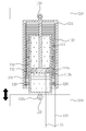
도 3은 도 2의 요부단면도이다.
도 4는 본 발명의 바람직한 실시 예에 따른 MR 댐퍼의 피스톤 실린더의 단면 상태를 나타낸 도면이다.
도 5는 본 발명의 바람직한 실시 예에 따른 MR 댐퍼의 댐퍼 실린더의 단면 상태를 나타낸 도면이다.
도 6은 본 발명의 바람직한 실시 예에 따른 MR 댐퍼의 댐퍼 실린더의 압축 이동하기 전의 단면 상태를 나타낸 도면이다.
도 7은 본 발명의 바람직한 실시 예에 따른 MR 댐퍼의 댐퍼 실린더의 압축 이동한 단면 상태를 나타낸 도면이다.BRIEF DESCRIPTION OF THE DRAWINGS FIG. 1 is a perspective view of an MR damper according to a preferred embodiment of the present invention; FIG.
Fig. 2 is a view showing the coupling state of Fig. 1. Fig.
3 is a sectional view of the main part of Fig.
4 is a sectional view of a piston cylinder of an MR damper according to a preferred embodiment of the present invention.
5 is a sectional view of a damper cylinder of an MR damper according to a preferred embodiment of the present invention.
6 is a cross-sectional view of the damper cylinder of the MR damper according to the preferred embodiment of the present invention before compression movement.
7 is a cross-sectional view of a damper cylinder of an MR damper according to a preferred embodiment of the present invention.
이하, 본 발명에 따른 에너지 하베스팅 기능을 갖는 MR 댐퍼의 바람직한 실시 예를 첨부된 도면에 의거하여 보다 구체적으로 설명한다.Hereinafter, preferred embodiments of an MR damper having an energy harvesting function according to the present invention will be described in more detail with reference to the accompanying drawings.
여기서, 하기의 모든 도면에서 동일한 기능을 갖는 구성요소는 동일한 참조부호를 사용하여 반복적인 설명은 생략하며, 아울러, 후술 되는 용어들은 본 발명에서의 기능을 고려하여 정의된 것으로서, 이것은 고유의 통용되는 의미로 해석되어야 함을 명시한다.Hereinafter, the same reference numerals will be used to denote the same or similar elements in all of the following drawings, and repetitive descriptions will be omitted. The following terms are defined in consideration of the functions of the present invention. It should be interpreted as meaning.
도 1 내지, 도 7에 도시된 바와 같이 본 발명은 피스톤 실린더(110)와 댐퍼 실린더(120) 및 전기에너지변환수단(130)으로 대별되어 이루어진다.As shown in FIGS. 1 to 7, the present invention is roughly divided into a
상기 피스톤 실린더(110)는 외 측으로 배치되고 내부 중앙에 피스톤 로드(111)가 형성되며, 상기 피스톤 로드(111)의 선단에는 피스톤(112)이 일체를 이루도록 형성된다.The
여기서, 상기 피스톤 실린더(110)의 내측에는 상기 전기에너지변환수단(130)의 코일(131)을 수용하기 위한 요(凹) 형의 코일 수용 홈(114)이 형성되는 것이 바람직하다.It is preferable that a recessed
이에 따라, 상기 댐퍼 실린더(120)를 수용, 결합시 추후 설명할 전기에너지변환수단(130)의 영구자석(132)과의 간격을 최대한 좁혀 전류를 높일 수 있고, 또 영구자석(132)과의 간섭 없이 댐퍼 실린더(120)의 이동과 자기장의 변화를 원활하게 이루도록 할 수 있다.Accordingly, when the
또, 상기 피스톤(112)에는 전자석(112a)이 내장되는 형태로 결합 되고, 상기 전자석(112a)에는 MR 댐퍼(100)의 구동에 필요한 전원을 공급하기 위한 전선(115)이 연결된다.The
또한, 상기 피스톤(112)에 결합 형성된 전자석(112a)의 일 측으로는 상기 댐퍼 실린더(120)의 내부로 충전되는 MR 유체(자기유변유체 : magnetorheological fluid)의 이동을 위한 유로(112b)가 형성된다.A
즉, 상기 유로(112b)는 피스톤 실린더(110)와 댐퍼 실린더(120)가 결합 되어 현가장치(210)와 함께 상, 하 완충동작시, 별도의 제어부(미도시)에 의해 자기력(자기장)이 가감 제어됨에 따라 상기 댐퍼 실린더(120)의 내부공간에 주입되어 자기력에 따라 점도가 변화하는 MR 유체의 유출/입 속도를 가감되도록 함으로써, 감쇠력을 발생토록 한다.The
예컨대, 차량의 현가장치(210)에 갑자기 큰 감쇠력이 요구될 경우, 제어부는 자기력을 많이 발생시키지 않도록 하여 MR 유체의 점도를 묽게 함으로써 상기 유로(112b)를 통해 많은 양이 빠르게 이동되도록 하여 댐퍼 실린더(120)를 피스톤 실린더(110)의 내부 일 측으로 빠르게 압축 이동시켜 작은 감쇠력을 나타내게 한다.For example, when a large damping force is suddenly required on the
한편, 상기한 압축 상태와는 반대의 동작을 위해서는 상기 MR 댐퍼(100)의 각 구성들이 그 역순으로 동작 된다.For the operation opposite to the above-described compression state, the respective components of the
또한, 차량의 현가장치(210)에 작은 감쇠력이 요구될 경우, 제어부는 자기력을 많이 발생시켜 MR 유체의 점도를 굳게 함으로써 상기 유로(112b)를 통해 적은 양이 느리게 이동되도록 하여 댐퍼 실린더(120)를 일 측으로 느리게 압축 이동시켜 큰 감쇠력을 나타내게 한다.In addition, when a small damping force is required for the
이러한 MR 유체의 제어에 대한 기술은 통상적인 것으로서 구체적인 설명은 생략하기로 한다.The description of the control of the MR fluid is conventional, and a detailed description thereof will be omitted.
그리고 상기 피스톤 실린더(110)의 일 측면에는 현가장치(210) 또는 차체(220) 등에 연결을 위한 연결구멍(113a)을 갖는 연결부(113)가 형성된다.A
즉, 본 발명에서 MR 댐퍼(100)의 피스톤 실린더(110)는 핀 또는 볼트, 너트와 같은 체결수단(미도시)을 이용하여 차체(220)에 고정되도록 장착(설치)되는 것이 바람직하다.That is, in the present invention, the
상기 댐퍼 실린더(120)는, 상기 피스톤 실린더(110)의 내부로 삽입, 결합 되고 내부에는 플로팅 피스톤(floating piston : 피스톤 측 및 연접봉 소단부(小端部) 양쪽에서 자유로이 회전할 수 있는 형식의 피스톤을 부동식이라고 하는데, 일반 고속 기관은 거의 이 형식을 채용하고 있다.)(121)이 이동가능 하도록 형성된다.The
또, 상기 댐퍼 실린더(120)는 일 측면에 현가장치(210) 또는 차체(220) 등에 연결을 위한 연결구멍(122a)을 갖는 연결부(122)가 형성된다.The
즉, 본 발명에서 MR 댐퍼(100)의 댐퍼 실린더(120)는 핀 또는 볼트, 너트와 같은 체결수단(미도시)을 이용하여 현가장치(210)에 이동 가능하도록 장착(설치)되는 것이 바람직하다.That is, in the present invention, it is preferable that the
상기 전기에너지변환수단(130)은 피스톤 실린더(110)의 내벽 면 측으로 형성되는 코일(131)과, 상기 댐퍼 실린더(120)의 외면으로 형성되는 영구자석(132)으로 이루어진다.The electric energy converting means 130 includes a
또, 상기 코일(131)에는 추후 차량의 운행시 현가장치(210)의 왕복 동작에 의한 운동에너지를 전기에너지로 변환시 코일(131)에서 발생하는 전류를 축전지(미도시) 등에 저장하기 위한 전선(133)이 연결된다.The
즉, 상기 전선(133)의 일단은 코일(131)과 연결되고 타 일단은 축전지(미도시)에 연결된다.That is, one end of the
여기서, 상기 코일(131)은 유도 코일(induction coil, Ruhmkorff coil)로 형성되고, 여러 겹으로 감겨지는 것이 바람직하다.Here, the
그리고 상기 코일(131)과 영구자석(132)은 상호 가까이 대향 하도록 형성되는 것이 전기에너지 생성을 위해 바람직하다.The
또한, 상기 영구자석(132)은 원통형으로 형성되는 것이 바람직하고, 하나로 형성할 수도 있으나, 상호 간격을 두고 복수 개를 배열시키는 것이 자속의 변화를 높여 안정된 전류를 얻을 수 있다.In addition, the
이와 같은 구성의 본 발명에 따른 전기에너지변환수단(130)은 차량의 주행중에 발생 되는 노면 충격과 진동을 흡수하기 위해 상, 하 동작하는 댐퍼 실린더(120)에 연동하여 영구자석(132)이 상기 피스톤 실린더(110)의 내벽 면 측에 대향 하여 설치된 상기 코일(131) 사이를 승, 하강함에 따라 자기장의 세기를 변화시켜 코일(131)에 유도전류를 발생시킴으로써 전기에너지를 생성하게 된다.The electric energy converting means 130 according to the present invention having the above-described structure is configured so that the
즉, 본 발명은 차량의 운행시 일상적으로 버려지거나 사용하지 않은 현가장치의 상, 하 운동에너지를 수확하여 사용 가능한 전기 에너지로 변환하는 에너지 하베스팅(energy harvesting)기능을 도모하도록 하는 것이다.That is, the present invention is intended to provide an energy harvesting function for harvesting up-and-down kinetic energy of a suspending device, which is routinely discarded or not used during operation of a vehicle, and converting the kinetic energy into usable electric energy.
이러한 에너지 하베스팅은 버려지는 운동에너지를 직접 전기 에너지로 획득할 수 있기 때문에 에너지 공급의 안정성, 보안성 및 지속 가능성을 유지할 수 있고, 환경공해를 줄일 수 있는 친환경 에너지 활용 기술이다.This energy harvesting is an eco-friendly energy utilization technology that can maintain the stability, security and sustainability of energy supply and reduce environmental pollution because it can acquire the kinetic energy that is abandoned directly as electric energy.
이와 같이 생성된 전기에너지는 상기 코일(131)에 일단이 연결되고 타 일단은 별도의 축전지(미도시)와 연결된 전선(133)을 통해 축전지에 저장된다.The electric energy thus generated is stored in the battery via one end connected to the
또, 상기 축전지에 저장된 전기에너지는 MR 댐퍼(100)를 동작시키기 위한 동력으로 사용하거나 다른 용도로 사용함으로써 에너지 효율을 높이고 전기에너지를 절약할 수 있다.In addition, the electric energy stored in the battery can be used as a power for operating the
상기와 같이 구성된 본 발명의 작용 상태를 설명하면 다음과 같다.The operation state of the present invention having the above-described structure will now be described.
먼저, 본 발명에 따른 MR 댐퍼(100)가 장착된 차량을 운행(주행)하게 되면 차량의 현가장치(210)가 노면 상태에 따라 승, 하강 왕복운동을 하면서 상, 하 진동을 흡수, 완충하여 승차감과 주행성을 향상시키게 된다.First, when the vehicle equipped with the
이때, 상기 MR 댐퍼(100) 또한 현가장치(210)의 상, 하 왕복운동에 연동하여 상, 하 왕복 운동하면서 운동에너지를 전기에너지로 변환 생성한다.At this time, the
이를 좀 더 구체적으로 설명하면 현가장치(210)의 상, 하 왕복운동에 연동하여 상기 댐퍼 실린더(120)가 피스톤 실린더(110)의 내부를 통해 압축 이동하거나 팽창 이동하게 된다.More specifically, the
이때, 상기 댐퍼 실린더(120)의 외면에 형성된 전기에너지변환수단(130)의 영구자석(132)이 댐퍼 실린더(120)에 연동하여 상기 피스톤 실린더(110)의 내벽 면 측에 대향 하여 설치된 상기 코일(131) 사이를 승, 하강하게 되면서 전자기장을 발생시켜 전기에너지를 생성하게 된다.The
즉, 상기 현가장치(210)의 상, 하 왕복운동에 연동하여 댐퍼 실린더(120)가 피스톤 실린더(110)의 내부를 지속적으로 압축 또는 팽창 이동하게 되면, 상기 영구자석(132)이 코일(131) 사이를 지속적으로 이동하면서 자기장의 변화를 발생시키게 되고, 자기장의 변화에 따라 코일에서 전류가 발생하여 전기에너지를 생성하게된다.That is, when the
이와 같이 생성된 전기에너지는 상기 코일(131)과 연결된 전선(133)을 통해 축전지에 저장하거나, MR 댐퍼(100)를 구동시키기 위한 동력으로 사용한다.The electric energy thus generated is stored in a battery via a
따라서, 본 발명에 따른 MR 댐퍼는 이와 같은 작용을 지속적으로 반복함으로써 차량의 운행시 버려지는 현가장치의 운동에너지를 전기에너지로 변환 생성하여 전기차나 하이브리드 차량의 에너지 효율을 높이고, 생성한 전기에너지를 MR 댐퍼 구동력으로 사용하여 배터리 용량을 최소화하여 비용을 절감할 수 있는 것이다.Therefore, the MR damper according to the present invention continuously repeats this action, thereby converting the kinetic energy of the suspension device, which is discarded when the vehicle is running, into electric energy, thereby increasing the energy efficiency of the electric vehicle or the hybrid vehicle, The MR damper is used as a driving force to minimize the battery capacity, thereby reducing the cost.
이상에서 설명한 본 발명은 전술한 실시 예 및 첨부된 도면에 의해 한정되는 것이 아니고, 본 발명의 기술적 사상을 벗어나지 않는 범위 내에서 여러 가지로 치환, 변형 및 균등한 타 실시 예로의 변경이 가능함은 본 발명이 속하는 기술분야에서 통상의 지식을 가진 자에게 있어서 명백할 것이다.It will be apparent to those skilled in the art that various modifications and variations can be made in the present invention without departing from the spirit or scope of the invention. And will be apparent to those skilled in the art to which the invention pertains.
100 : MR 댐퍼 110 : 피스톤 실린더
111 : 피스톤 로드 112 : 피스톤
112a : 전자석 112b : 유로
113 : 연결부 113a : 연결구멍
114 : 코일 수용 홈 115 : 전선
120 : 댐퍼 실린더 121 : 플로팅 피스톤
122 : 연결부 122a : 연결구멍
130 : 전기에너지변환수단 131 : 코일
132 : 영구자석 133 : 전선
210 : 현가장치 220 : 차체100: MR damper 110: piston cylinder
111: Piston rod 112: Piston
112a:
113: connecting
114: coil receiving groove 115:
120: Damper cylinder 121: Floating piston
122:
130: electric energy converting means 131: coil
132: permanent magnet 133: wire
210: Suspension device 220: Body
Claims (4)
외 측으로 배치되고 내부 중앙에 피스톤 로드가 형성되며, 상기 피스톤 로드의 선단에는 전자석을 갖는 피스톤이 일체를 이루도록 형성되는 피스톤 실린더와;
상기 피스톤 실린더의 내부로 삽입, 결합 되고 내부에는 플로팅 피스톤(floating piston이 이동가능 하도록 형성된 댐퍼 실린더와;
상기 피스톤 실린더의 내벽 면 측으로 형성되는 코일과, 상기 댐퍼 실린더의 외면으로 배열시킨 영구자석으로 이루어지는 전기에너지변환수단; 을 포함하여 이루어지는 것을 특징으로 하는 에너지 하베스팅 기능을 갖는 MR 댐퍼.In the MR damper,
A piston cylinder disposed at an outer side thereof and having a piston rod formed at an inner center thereof, and a piston having an electromagnet formed integrally therewith at the tip of the piston rod;
A damper cylinder inserted and coupled to the inside of the piston cylinder and having a floating piston movably installed therein;
Electric energy converting means comprising a coil formed on an inner wall surface side of the piston cylinder and a permanent magnet arranged on the outer surface of the damper cylinder; And an energy damper having an energy harvesting function.
상기 피스톤 실린더의 내측에는 요(凹) 형의 코일 수용 홈이 형성되는 것을 특징으로 하는 에너지 하베스팅 기능을 갖는 MR 댐퍼.The method according to claim 1,
And an MR damper having an energy harvesting function, wherein a recessed coil receiving groove is formed inside the piston cylinder.
상기 코일에는 현가장치의 왕복 동작에 의한 운동에너지를 전기에너지로 변환시 코일에서 발생하는 전류를 저장하기 위한 전선이 연결되는 것을 특징으로 하는 에너지 하베스팅 기능을 갖는 MR 댐퍼.The method according to claim 1,
Wherein an electric wire for storing a current generated in the coil is connected to the coil when the kinetic energy due to the reciprocating motion of the suspension device is converted into electric energy.
상기 영구자석은 원통형으로 형성되고, 상호 간격을 복수 개를 배열시키는 것을 특징으로 하는 에너지 하베스팅 기능을 갖는 MR 댐퍼.The method according to claim 1,
Wherein the permanent magnets are formed in a cylindrical shape, and a plurality of the permanent magnets are spaced apart from each other, the MR damper having an energy harvesting function.
Priority Applications (1)
| Application Number | Priority Date | Filing Date | Title |
|---|---|---|---|
| KR1020160035887A KR20170113781A (en) | 2016-03-25 | 2016-03-25 | MR damper have functions of energy harvesting |
Applications Claiming Priority (1)
| Application Number | Priority Date | Filing Date | Title |
|---|---|---|---|
| KR1020160035887A KR20170113781A (en) | 2016-03-25 | 2016-03-25 | MR damper have functions of energy harvesting |
Publications (1)
| Publication Number | Publication Date |
|---|---|
| KR20170113781A true KR20170113781A (en) | 2017-10-13 |
Family
ID=60139720
Family Applications (1)
| Application Number | Title | Priority Date | Filing Date |
|---|---|---|---|
| KR1020160035887A KR20170113781A (en) | 2016-03-25 | 2016-03-25 | MR damper have functions of energy harvesting |
Country Status (1)
| Country | Link |
|---|---|
| KR (1) | KR20170113781A (en) |
Cited By (4)
| Publication number | Priority date | Publication date | Assignee | Title |
|---|---|---|---|---|
| CN108591346A (en) * | 2018-06-18 | 2018-09-28 | 北京光宇之勋科技有限公司 | A kind of combined type damping |
| KR102066983B1 (en) | 2018-12-05 | 2020-01-16 | 영남대학교 산학협력단 | Energy Harvesting Hydraulic Damper Using Blades and Rotary Generator |
| CN111152616A (en) * | 2020-01-08 | 2020-05-15 | 合肥工业大学 | Magnetorheological damping suspension and measurement and control method thereof |
| CN115182953A (en) * | 2022-08-02 | 2022-10-14 | 成都工业学院 | New energy automobile damping device |
-
2016
- 2016-03-25 KR KR1020160035887A patent/KR20170113781A/en not_active Application Discontinuation
Cited By (5)
| Publication number | Priority date | Publication date | Assignee | Title |
|---|---|---|---|---|
| CN108591346A (en) * | 2018-06-18 | 2018-09-28 | 北京光宇之勋科技有限公司 | A kind of combined type damping |
| KR102066983B1 (en) | 2018-12-05 | 2020-01-16 | 영남대학교 산학협력단 | Energy Harvesting Hydraulic Damper Using Blades and Rotary Generator |
| CN111152616A (en) * | 2020-01-08 | 2020-05-15 | 合肥工业大学 | Magnetorheological damping suspension and measurement and control method thereof |
| CN111152616B (en) * | 2020-01-08 | 2022-09-27 | 合肥工业大学 | Magnetorheological damping suspension and measurement and control method thereof |
| CN115182953A (en) * | 2022-08-02 | 2022-10-14 | 成都工业学院 | New energy automobile damping device |
Similar Documents
| Publication | Publication Date | Title |
|---|---|---|
| CN106678256B (en) | A kind of electric vehicle magneto-electric self-powered suspension damper | |
| CN104309438B (en) | A kind of multi-state vehicle suspension | |
| Jin-qiu et al. | A review on energy-regenerative suspension systems for vehicles | |
| US20120061893A1 (en) | Kinetic energy management system | |
| KR20170113781A (en) | MR damper have functions of energy harvesting | |
| CN101865237A (en) | Hydraulic electricity generation shock absorber of vehicle | |
| CN105276068B (en) | A kind of automobile absorber generating mechanism based on hydraulic tube | |
| CN105711368A (en) | Electromagnetic energy harvesting system based on passive suspension | |
| CN104455166A (en) | Automobile and hydraulic damping energy recovery device thereof | |
| CN103470672A (en) | Active pump type energy-regenerative damping system | |
| CN103192673A (en) | Semi-active suspension energy-regenerative device of hybrid vehicle | |
| CN102926956A (en) | Blade-type energy recovery shock absorber | |
| CN105041938A (en) | Vibration reducer of electric vehicle | |
| CN104675903A (en) | Hydraulic damper capable of generating electricity | |
| CN101749354B (en) | Automobile generating shock absorber | |
| CN204493557U (en) | A kind of hydraulic damper generated electricity | |
| KR101238278B1 (en) | Shock absorber for vehicle including linear generator | |
| CN202301732U (en) | Automotive shock absorber with shock resistance | |
| CN206374493U (en) | Automobile suspension system and its mixed type actuator | |
| CN213870882U (en) | Compression buffer structure of shock absorber | |
| CN108895112A (en) | A kind of MR fluid shock absorber | |
| CN204278987U (en) | A kind of multi-state vehicle suspension | |
| CN202326867U (en) | Magnetoelectricity shock absorber and voltage converter thereof | |
| CN202284623U (en) | Automobile vibration damper | |
| CN107461447A (en) | Damping device with totally-enclosed stiffness variable damping system and linear generating system |
Legal Events
| Date | Code | Title | Description |
|---|---|---|---|
| A201 | Request for examination | ||
| E902 | Notification of reason for refusal | ||
| E601 | Decision to refuse application |