KR20170112214A - ceiling-type Band for fixed ducts - Google Patents
ceiling-type Band for fixed ducts Download PDFInfo
- Publication number
- KR20170112214A KR20170112214A KR1020160038952A KR20160038952A KR20170112214A KR 20170112214 A KR20170112214 A KR 20170112214A KR 1020160038952 A KR1020160038952 A KR 1020160038952A KR 20160038952 A KR20160038952 A KR 20160038952A KR 20170112214 A KR20170112214 A KR 20170112214A
- Authority
- KR
- South Korea
- Prior art keywords
- band
- ceiling
- nut
- insertion hole
- nut member
- Prior art date
Links
Images


Classifications
-
- F—MECHANICAL ENGINEERING; LIGHTING; HEATING; WEAPONS; BLASTING
- F24—HEATING; RANGES; VENTILATING
- F24F—AIR-CONDITIONING; AIR-HUMIDIFICATION; VENTILATION; USE OF AIR CURRENTS FOR SCREENING
- F24F13/00—Details common to, or for air-conditioning, air-humidification, ventilation or use of air currents for screening
- F24F13/02—Ducting arrangements
- F24F13/0254—Ducting arrangements characterised by their mounting means, e.g. supports
-
- F—MECHANICAL ENGINEERING; LIGHTING; HEATING; WEAPONS; BLASTING
- F16—ENGINEERING ELEMENTS AND UNITS; GENERAL MEASURES FOR PRODUCING AND MAINTAINING EFFECTIVE FUNCTIONING OF MACHINES OR INSTALLATIONS; THERMAL INSULATION IN GENERAL
- F16L—PIPES; JOINTS OR FITTINGS FOR PIPES; SUPPORTS FOR PIPES, CABLES OR PROTECTIVE TUBING; MEANS FOR THERMAL INSULATION IN GENERAL
- F16L3/00—Supports for pipes, cables or protective tubing, e.g. hangers, holders, clamps, cleats, clips, brackets
- F16L3/08—Supports for pipes, cables or protective tubing, e.g. hangers, holders, clamps, cleats, clips, brackets substantially surrounding the pipe, cable or protective tubing
- F16L3/10—Supports for pipes, cables or protective tubing, e.g. hangers, holders, clamps, cleats, clips, brackets substantially surrounding the pipe, cable or protective tubing divided, i.e. with two or more members engaging the pipe, cable or protective tubing
- F16L3/1008—Supports for pipes, cables or protective tubing, e.g. hangers, holders, clamps, cleats, clips, brackets substantially surrounding the pipe, cable or protective tubing divided, i.e. with two or more members engaging the pipe, cable or protective tubing with two members engaging the pipe, cable or tubing, both being made of thin band material completely surrounding the pipe
-
- F—MECHANICAL ENGINEERING; LIGHTING; HEATING; WEAPONS; BLASTING
- F16—ENGINEERING ELEMENTS AND UNITS; GENERAL MEASURES FOR PRODUCING AND MAINTAINING EFFECTIVE FUNCTIONING OF MACHINES OR INSTALLATIONS; THERMAL INSULATION IN GENERAL
- F16L—PIPES; JOINTS OR FITTINGS FOR PIPES; SUPPORTS FOR PIPES, CABLES OR PROTECTIVE TUBING; MEANS FOR THERMAL INSULATION IN GENERAL
- F16L3/00—Supports for pipes, cables or protective tubing, e.g. hangers, holders, clamps, cleats, clips, brackets
- F16L3/08—Supports for pipes, cables or protective tubing, e.g. hangers, holders, clamps, cleats, clips, brackets substantially surrounding the pipe, cable or protective tubing
- F16L3/12—Supports for pipes, cables or protective tubing, e.g. hangers, holders, clamps, cleats, clips, brackets substantially surrounding the pipe, cable or protective tubing comprising a member substantially surrounding the pipe, cable or protective tubing
Landscapes
- Engineering & Computer Science (AREA)
- General Engineering & Computer Science (AREA)
- Mechanical Engineering (AREA)
- Chemical & Material Sciences (AREA)
- Combustion & Propulsion (AREA)
- Duct Arrangements (AREA)
- Clamps And Clips (AREA)
Abstract
본 발명은 “┌┐”형상으로 절곡되어 형성되되, 일측에 볼트부재(140)가 체결되는 체결공(111)과, 상부에 천장연결부재(150)가 장착되는 장착공(112)을 포함하는 찬넬부(110);와, 상기 찬넬부(110)의 타측으로부터 그 일측이 연결되어 형성되는 원형밴드부(120);와, 상기 원형밴드부(120)의 타측으로부터 상부방향으로 절곡되어 상기 찬넬부(110)의 일측과 대응되도록 형성되되, 그 중앙에 너트부재(160)가 삽입되는 삽입공(131)이 형성되는 연결플레이트(130);로 구성되어, 상기 볼트부재(140)가 상기 체결공(111)에 체결되어 고정된 상태에서 상기 연결플레이트(130)에 연결된 상기 너트부재(160)가 상기 볼트부재(140)의 나사산부(141)와 결합되어 상기 찬넬부(110)의 일측과 상기 연결플레이트(130)의 타측이 맞닿는 것을 특징으로 한다.The present invention includes a fastening hole 111 formed by bending in the form of "┌┐" to fasten a bolt member 140 to one side, and a mounting hole 112 on which a ceiling connecting member 150 is mounted A circular band part 120 formed by connecting one side of the channel part 110 from the other side of the channel part 110 and a circular band part 120 bent upward from the other side of the circular band part 120, And a connecting plate 130 formed to correspond to one side of the bolt member 110 and having an insertion hole 131 into which a nut member 160 is inserted, The nut member 160 connected to the connection plate 130 is engaged with the threaded portion 141 of the bolt member 140 to be connected to one side of the channel unit 110, And the other side of the plate 130 abuts.
Description
본 발명은 천장용 덕트고정밴드에 관한 것으로서, 건축물 내부의 천정에 설치되는 덕트(미도시)를 고정시키는 천장용 덕트고정밴드(100)에 있어서, “┌┐”형상으로 절곡되어 형성되되, 일측에 볼트부재(140)가 체결되는 체결공(111)과, 상부에 천장연결부재(150)가 장착되는 장착공(112)을 포함하는 찬넬부(110);와, 상기 찬넬부(110)의 타측으로부터 그 일측이 연결되어 형성되는 원형밴드부(120);와, 상기 원형밴드부(120)의 타측으로부터 상부방향으로 절곡되어 상기 찬넬부(110)의 일측과 대응되도록 형성되되, 그 중앙에 너트부재(160)가 삽입되는 삽입공(131)이 형성되는 연결플레이트(130);로 구성되어, 상기 볼트부재(140)가 상기 체결공(111)에 체결되어 고정된 상태에서 상기 연결플레이트(130)에 연결된 상기 너트부재(160)가 상기 볼트부재(140)의 나사산부(141)와 결합되어 상기 찬넬부(110)의 일측과 상기 연결플레이트(130)의 타측이 맞닿는 것을 특징으로 하는 천장용 덕트고정밴드에 관한 것이다.A ceiling duct fixing band (100) for fixing a duct (not shown) installed in a ceiling inside a building, the ceiling duct fixing band (100) being formed by being bent in a shape of " A
일반적으로, 덕트란 공기 또는 유체가 흐르는 통로가 형성된 건축자재로서, 주로 공조기와 연결되어 건출물의 실내와 외부를 연통시켜 공기를 순환하여 정화시키는 역할을 한다.Generally, a duct is a building material in which air or a passage of a fluid is formed, and is mainly connected to an air conditioner to communicate the inside and outside of the outdoor to circulate and purify the air.
이러한 덕트는 미관상 보통 천장에 설치되는 것이 대부분이며, 상기 덕트를 천장에 고정시키기 위하여 천장에 설치되어 덕트를 고정시키는 링형상의 덕트고정밴드가 사용된다.Most of such ducts are installed on a ceiling usually on a ceiling, and ring-shaped duct fixing bands are used to fix the ducts on the ceiling to fix the ducts to the ceiling.
이와 같은 덕트고정밴드 중 그 일실시예로 하기 특허문헌 1의 “공기덕트 고정용 클램프구조(대한민국 등록실용신안공보 제20-0283484호)”가 게시되어 있다.As one example of such a duct fixing band, a "clamp structure for fixing an air duct (Korean Utility Model Registration Utility Model No. 20-0283484") of Patent Document 1 is posted.
상기 특허문헌 1의 “공기덕트 고정용 클램프구조”는 고정밴드(4) 내주면에 고정구비되어 공기덕트(3) 둘레에 밀착되는 탄성재의 보호부재(5)와 상측의 관통구멍(10)을 향하도록 양측에 랜싱돌기(11)가 절곡형성되는 결합편(8)과 둘레가 상기 관통구멍(10) 내에 위치되고 하단에 플랜지(15)가 형성되어 상기 랜싱돌기(11) 단부에 위치되는 결합너트(14)가 구비되어 결합너트(14)가 결합편(8)에 대해 자유롭게 회전되도록 결합되어 있기 때문에 공기덕트(3)의 설치위치에 따라 고정밴드(4)를 자유롭게 회전시킬 수 있다는 장점이 있었다.The "air duct fixing clamp structure" of Patent Document 1 is fixed to the inner circumferential surface of the fixing band 4 and is attached to the protection member 5 of the elastic material closely attached to the air duct 3 and the upper through- And a flange 15 is formed at the lower end of the engaging piece 8. The flange 15 is located at the end of the lancing protrusion 11, Since the coupling nut 14 is provided so as to be freely rotatable with respect to the coupling piece 8, the fixing band 4 can be freely rotated according to the installation position of the air duct 3 .
그러나, 상기 특허문헌 1의 “공기덕트 고정용 클램프구조”는 고정밴드를 통해 공기덕트를 천장에 고정시키는 과정에서 천장에 설치된 앵커볼트에 너트결합부를 결합시키고, 공기덕트를 천장으로 이동하여 고정밴드에 공기덕트를 끼운 후 너트결합부와 고정밴드를 결합볼트와 너트를 이용하여 체결하는 구조로 이루어져 결합볼트와 너트 체결시, 공기덕트를 팔로 지지한 상태에서 양손으로 결합볼트와 너트를 각각 잡고 체결함으로써, 덕트고정작업이 어려워 작업자의 피로도가 증가된다는 문제점이 있었다.However, in the "clamp structure for fixing the air duct" of Patent Document 1, the nut coupling portion is joined to the anchor bolt provided on the ceiling in the process of fixing the air duct to the ceiling through the fixing band, and the air duct is moved to the ceiling, And the nut and the fixing band are fastened together using bolts and nuts. When the bolts and nuts are fastened, hold the bolts and nuts with both hands while holding the air ducts with the arms. There is a problem that the work for fixing the duct is difficult and the fatigue of the worker is increased.
본 발명은 상술한 문제점을 해결하고자 안출된 것으로서, 본 발명의 목적은 볼트부재가 찬넬부에 고정되어 형성되고, 연결플레이트에 너트부재가 삽입된 상태에서 전, 후, 상, 하로 이동가능하게 구성함으로써, 천장에 설치된 앵커볼트에 찬넬부에 형성된 천장연결부재가 결합되고 덕트가 원형밴드부에 삽입된 상태에서 한 손만을 이용하여 볼트부재와 너트부재가 체결가능하게 구성됨으로써, 덕트고정작업이 수월해져 작업자의 피로도가 감소되는 천장용 덕트고정밴드를 제공하는 것이다.SUMMARY OF THE INVENTION The present invention has been conceived to solve the above-described problems, and it is an object of the present invention to provide a bolt member which is formed by being fixed to a channel portion and is movable in front, A bolt member and a nut member can be fastened to each other by using only one hand in a state where a ceiling connecting member formed in a channel portion is coupled to an anchor bolt installed in a ceiling and a duct is inserted in a circular band portion, Thereby providing a ceiling duct fixing band in which the operator's fatigue is reduced.
상기와 같은 문제점을 해결하기 위하여, 본 발명에 따른 천장용 덕트고정밴드(100)는, “┌┐”형상으로 절곡되어 형성되되, 일측에 볼트부재(140)가 체결되는 체결공(111)과, 상부에 천장연결부재(150)가 장착되는 장착공(112)을 포함하는 찬넬부(110);와, 상기 찬넬부(110)의 타측으로부터 그 일측이 연결되어 형성되는 원형밴드부(120);와, 상기 원형밴드부(120)의 타측으로부터 상부방향으로 절곡되어 상기 찬넬부(110)의 일측과 대응되도록 형성되되, 그 중앙에 너트부재(160)가 삽입되는 삽입공(131)이 형성되는 연결플레이트(130);로 구성되어, 상기 볼트부재(140)가 상기 체결공(111)에 체결되어 고정된 상태에서 상기 연결플레이트(130)에 연결된 상기 너트부재(160)가 상기 볼트부재(140)의 나사산부(141)와 결합되어 상기 찬넬부(110)의 일측과 상기 연결플레이트(130)의 타측이 맞닿는 것을 특징으로 한다.In order to solve the above-described problems, the ceiling
또한, 상기 너트부재(160)는, 상기 삽입공(131)의 지름보다 크게 형성되는 너트머리부(161)와, 상기 너트머리부(161)로부터 연장형성되되, 그 지름이 상기 삽입공(131)의 지름과 작거나 동일하게 형성되는 몸통부(162)와, 상기 몸통부(162)의 외측둘레에 상기 몸통부(162)가 상기 삽입공(131)에 삽입된 상태에서 상기 너트부재(160)가 외부로 이탈되는 것을 방지하는 걸림턱부(163)와, 상기 너트머리부(161) 및 상기 몸통부(162)의 내측에 상기 볼트부재(140)의 나사산부(141)가 통과되는 통과공(164)이 형성되는 것을 특징으로 한다.The
또한, 상기 너트부재(160)는, 상기 몸통부(162)가 상기 삽입공(131)에 삽입된 상태에서 전, 후방향으로 이동되는 것을 특징으로 한다.The
또한, 상기 삽입공(131)은, 상기 몸통부(162)가 상기 삽입공(131)에 삽입된 상태에서 상기 너트부재(160)가 상, 하방향으로 이동가능하도록 장공형상으로 형성되는 것을 특징으로 한다.The
또한, 상기 원형밴드부(120)는, 두 개의 반편(半偏)으로 형성된 제1 밴드(121)와 제2 밴드(122)로 구성되고, 상기 제1 밴드(121)의 일측과 상기 제2 밴드(122)의 타측은 힌지결합되는 것을 특징으로 한다.The
이상, 상술한 바와 같이 본 발명에 따르면, 볼트부재가 찬넬부에 고정되어 형성되고, 연결플레이트에 너트부재가 삽입된 상태에서 전, 후, 상, 하로 이동가능하게 구성함으로써, 천장에 설치된 앵커볼트에 찬넬부에 형성된 천장연결부재가 결합되고 덕트가 원형밴드부에 삽입된 상태에서 한 손만을 이용하여 볼트부재와 너트부재가 체결가능하게 구성됨으로써, 덕트고정작업이 수월해져 작업자의 피로도가 감소된다는 장점이 있다.As described above, according to the present invention, since the bolt member is fixed to the channel portion and is movable in the forward, backward, up and down directions with the nut member inserted into the connecting plate, the anchor bolt And the duct member is inserted into the circular band portion, and the bolt member and the nut member can be fastened using only one hand in a state where the duct is inserted into the circular band portion. Thus, the duct fixing operation is facilitated and the fatigue of the worker is reduced .
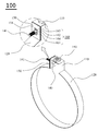
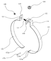
도 1은 본 발명의 바람직한 실시예에 따른 천장용 덕트고정밴드의 전체 모습을 보인 사시도
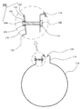
도 2는 본 발명의 바람직한 실시예에 따른 천장용 덕트고정밴드의 분해된 모습을 보인 사시도
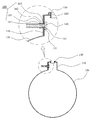
도 3은 본 발명의 바람직한 실시예에 따른 천장용 덕트고정밴드의 구성 중 볼트부재와 너트부재가 결합되는 과정을 보인 실시예도
도 4는 본 발명의 바람직한 실시예에 따른 천장용 덕트고정밴드의 구성 중 볼트부재와 너트부재가 결합되는 과정을 보인 실시예도
도 5는 본 발명의 바람직한 실시예에 따른 천장용 덕트고정밴드의 구성 중 볼트부재와 너트부재가 결합된 모습을 보인 실시예도
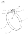
도 6은 본 발명의 바람직한 다른 실시예에 따른 천장용 덕트고정밴드의 전체 모습을 보인 사시도
도 7은 본 발명의 바람직한 다른 실시예에 따른 천장용 덕트고정밴드의 분해된 모습을 보인 사시도BRIEF DESCRIPTION OF THE DRAWINGS FIG. 1 is a perspective view of a ceiling duct fixing band according to a preferred embodiment of the present invention; FIG.
2 is a perspective view showing an exploded view of a ceiling duct fixing band according to a preferred embodiment of the present invention.
FIG. 3 is a perspective view illustrating a process of assembling a bolt member and a nut member in a structure of a ceiling duct fixing band according to a preferred embodiment of the present invention
FIG. 4 is a perspective view illustrating the assembly of a bolt member and a nut member in a structure of a ceiling duct fixing band according to a preferred embodiment of the present invention.
FIG. 5 is a perspective view illustrating an embodiment in which a bolt member and a nut member are combined in a configuration of a ceiling duct fixing band according to a preferred embodiment of the present invention
FIG. 6 is a perspective view of a ceiling duct fixing band according to another preferred embodiment of the present invention.
7 is a perspective view illustrating an exploded view of a ceiling duct fixing band according to another preferred embodiment of the present invention.
이하에서는 첨부된 도면을 참조로 하여, 본 발명의 일 실시예에 따른 천장용 덕트고정밴드(100)를 상세히 설명한다. 우선, 도면들 중, 동일한 구성요소 또는 부품들은 가능한 한 동일한 참조부호로 나타내고 있음에 유의하여야 한다. 본 발명을 설명함에 있어, 관련된 공지 기능 혹은 구성에 관한 구체적인 설명은 본 발명의 요지를 모호하지 않게 하기 위하여 생략한다.Hereinafter, a ceiling
도 1 및 도 2를 참조하여, 본 발명의 일 실시예에 따른 천장용 덕트고정밴드(100)는 크게 찬넬부(110), 원형밴드부(120) 및 연결플레이트(130)로 구성된다.Referring to FIGS. 1 and 2, a ceiling
먼저, 찬넬부(110)에 대하여 설명한다. 상기 찬넬부(110)는 도 1 또는 도 2에 나타낸 것과 같이, “┌┐”형상으로 절곡형성되는 구성요소로서, 상기 찬넬부(110)의 일측에는 볼트부재(140)가 체결되도록 체결공(111)이 타공형성된다.First, the
이 경우, 상기 체결공(111)의 내측에는 나사산(미도시)이 형성됨으로써, 상기 볼트부재(140)가 볼팅조임되어 상기 찬넬부(110)에 상기 볼트부재(140)가 고정결합되는 것을 가능하게 한다.In this case, a screw thread (not shown) is formed inside the
한편, 상기 체결공(111)의 내측이 매끈하게 형성되는 경우, 상기 볼트부재(140)를 상기 체결공(111)에 삽입한 상태에서 용접를 통해 상기 볼트부재(140)를 상기 찬넬부(110)에 고정시키는 것도 가능하다.When the
한편, 상기 찬넬부(110)의 상부에는 앵커볼트(미도시)와 결합되는 천정연결부재(150)가 장착되는 장착공(112)이 타공형성됨으로써, 천장에 설치된 앵커볼트(미도시)와 상기 천정연결부재(150)가 연결되어 천장용 덕트고정밴드(100)를 공중에 위치시키는 것을 가능하게 한다.A
다음으로, 원형밴드부(120)에 대하여 설명한다. 상기 원형밴드부(120)는 도 1 또는 도 2에 나타낸 것과 같이, 상기 찬넬부(110)의 타측으로부터 그 일측이 연결되어 형성되는 일종의 띠형상의 원형밴드로 덕트(미도시)를 감싸 천장에 위치되는 상기 덕트(미도시)를 지지하는 구성요소로서, 소정의 힘이 가해지면 변형되었다가 소정의 힘이 제거되면 원상태로 복귀되도록 형성되는 것이 바람직하다.Next, the
다음으로, 연결플레이트(130)에 대하여 설명한다. 상기 연결플레이트(130)는 도 1 또는 도 2에 나타낸 것과 같이, 상기 원형밴드부(120)의 타측으로부터 상부방향으로 절곡되어 상기 찬넬부(110)의 일측과 대응되도록 형성되는 구성요소로서, 상기 연결플레이트(130)의 중앙에는 너트부재(160)가 삽입되도록 삽입공(131)이 형성된다.Next, the
한편, 상기 너트부재(160)는 상기 삽입공(131)에 삽입된 상태에서 외부로 이탈되지 않고 전, 후, 상, 하방향으로 이동이 가능하도록 구성되는 것이 바람직하고, 그 일실시예로는 상기 삽입공(131)의 지름보다 크게 형성되는 너트머리부(161)와, 상기 너트머리부(161)로부터 연장형성되되, 그 지름이 상기 삽입공(131)의 지름과 작거나 동일하게 형성되는 몸통부(162)와, 상기 몸통부(162)의 외측둘레에 상기 몸통부(162)가 상기 삽입공(131)에 삽입된 상태에서 상기 너트부재(160)가 외부로 이탈되는 것을 방지하는 걸림턱부(163)와, 상기 너트머리부(161) 및 상기 몸통부(162)의 내측에 상기 볼트부재(140)의 나사산부(141)가 통과되는 통과공(164)이 형성되는 것이 가능하다.The
이때, 상기 삽입공(131)은 상기 몸통부(162)가 상기 삽입공(131)에 삽입된 상태에서 상기 너트부재(160)가 상, 하방향으로 이동가능하도록 장공형상으로 형성되는 것이 바람직하다.In this case, the
이하에서는, 도 3 내지 도 5를 참조하여 본 발명의 일실시예에 따른 천장용 덕트고정밴드(100)의 결합방법에 대하여 설명한다.Hereinafter, a method of joining the ceiling
먼저, 상기 앵커볼트(미도시)에 상기 천정연결부재(150)를 결합하여 상기 천장용 덕트고정밴드(100)를 공중에 위치시킨다.First, the
이후 작업자는 한 손으로 상기 원형밴드부(120)를 파지하고 소정의 힘을 가하여 변형시킨 후 상기 덕트(미도시)를 거치한 후 상기 원형밴드부(120)를 파지한 손을 상기 너트부재(160)로 이동시켜 상기 너트부재(160)를 파지한다.Then, the operator grasps the
다음으로 작업자는 상기 너트부재(160)를 파지한 손으로 상기 너트부재(160)를 상, 하 , 전, 후방향으로 이동하여 상기 볼트부재(140)의 나사산부(141)가 상기 너트부재(160)의 통과공(164)에 삽입되도록 위치를 맞춘다.The operator moves the
상기 볼트부재(140)의 나사산부(141)가 상기 너트부재(160)의 통과공(164)에 삽입되면, 작업자는 상기 너트부재(160)를 회전시켜 상기 볼트부재(140)와 상기 너트부재(160)를 볼팅결합시킨다. When the threaded
이때, 상기 볼트부재(140)는 상기 찬넬부(110)에 고정된 상태에서 상기 너트부재(160)의 회전력에 의해 상기 너트부재(160)의 방향으로 전진함으로써, 상기 찬넬부(110)와 상기 연결플레이트(130)가 접촉하여 긴밀한 결합이 이루어진다.At this time, the
이와 같은 결합방법에 의하여, 천장에 설치된 상기 앵커볼트(미도시)에 상기 찬넬부(110)에 형성된 천장연결부재(150)가 결합되고, 상기 덕트(미도시)가 상기 원형밴드부(120)에 삽입된 상태에서, 작업자는 한 손만을 이용하여 상기 볼트부재(140)와 상기 너트부재(160)를 간편하게 체결할 수 있음으로써, 작업자의 피로도가 감소되어 안전사고 예방 및 작업능률이 향상되는 것이 가능해 진다.The
한편, 상기 원형밴드부(120)의 다른 일실시예로 도 6 또는 도 7에 나타낸 것과 같이, 상기 원형밴드부(120)를 두 개의 반편(半偏)으로 형성된 제1 밴드(121)와 제2 밴드(122)로 각각 나누어 형성될 수 있다.6 or 7, the
이때, 상기 제1 밴드(121)의 일측과 상기 제2 밴드(122)의 타측에는 각각 제1 연결관(121a)와 제2 연결관(122a) 및 삽입홈(121b)이 형성되어 상기 제1 밴드(121)의 일측과 상기 제2 밴드(122)의 타측이 연결된 상태에서 연결핀(170)을 이용하여 힌지결합됨으로써, 상기 천장용 덕트고정밴드(100)에 상기 덕트(미도시)가 설치된 상태에서 상기 덕트(미도시)의 교체 또는 해체시, 상기 연결핀(170)을 제거하여 간단하게 상기 덕트(미도시)를 상기 천장용 덕트고정밴드(100)로부터 분리하는 것을 가능하게 한다.At this time, a
도면과 명세서에서 최적 실시 예들이 개시되었다. 여기서 특정한 용어들이 사용되었으나, 이는 단지 본 발명을 설명하기 위한 목적에서 사용된 것이지 의미한정이나 특허청구범위에 기재된 본 발명의 범위를 제한하기 위하여 사용된 것은 아니다. 그러므로 본 기술 분야의 통상의 지식을 가진 자라면 이로부터 다양한 변형 및 균등한 타 실시 예가 가능하다는 점을 이해할 것이다. 따라서 본 발명의 진정한 기술적 보호범위는 첨부된 특허청구범위의 기술적 사상에 의해 정해져야 할 것이다.Optimal embodiments have been disclosed in the drawings and specification. Although specific terms have been employed herein, they are used for purposes of illustration only and are not intended to limit the scope of the invention as defined in the claims or the claims. Therefore, those skilled in the art will appreciate that various modifications and equivalent embodiments are possible without departing from the scope of the present invention. Accordingly, the true scope of the present invention should be determined by the technical idea of the appended claims.
100: 천장용 덕트고정밴드
110: 찬넬부
111: 체결공
112: 장착공
120: 원형밴드부
121: 제1 밴드
121a: 제1 연결관
121b: 삽입홈
122: 제2 밴드
122a: 제2 연결관
130: 연결플레이트
131: 삽입공
140: 볼트부재
141: 나사산부
150: 천장연결부재
160: 너트부재
161: 너트머리부
162: 몸통부
163: 걸림턱부
164: 통과공
170: 연결핀100: Ceiling duct fixing band 110: Channel section
111: fastening hole 112: mounting hole
120: circular band portion 121: first band
121a:
122:
130: connection plate 131: insertion hole
140: bolt member 141:
150: Ceiling connection member
160: nut member 161: nut head
162: body part 163:
164: Through hole
170: connecting pin
Claims (5)
“┌┐”형상으로 절곡되어 형성되되, 일측에 볼트부재(140)가 체결되는 체결공(111)과, 상부에 천장연결부재(150)가 장착되는 장착공(112)을 포함하는 찬넬부(110);
상기 찬넬부(110)의 타측으로부터 그 일측이 연결되어 형성되는 원형밴드부(120);
상기 원형밴드부(120)의 타측으로부터 상부방향으로 절곡되어 상기 찬넬부(110)의 일측과 대응되도록 형성되되, 그 중앙에 너트부재(160)가 삽입되는 삽입공(131)이 형성되는 연결플레이트(130);로 구성되어,
상기 볼트부재(140)가 상기 체결공(111)에 체결되어 고정된 상태에서 상기 연결플레이트(130)에 연결된 상기 너트부재(160)가 상기 볼트부재(140)의 나사산부(141)와 결합되어 상기 찬넬부(110)의 일측과 상기 연결플레이트(130)의 타측이 맞닿는 것을 특징으로 하는 천장용 덕트고정밴드(100).A ceiling duct fixing band (100) for fixing a duct (not shown) installed on a ceiling inside a building,
And a mounting hole 112 in which a bolt member 140 is fastened to one side and a ceiling connecting member 150 is mounted on the upper side, 110);
A circular band portion 120 connected to one side of the channel portion 110 from the other side thereof;
A connecting plate 130 formed to correspond to one side of the channel section 110 and bent at an upper side from the other side of the circular band section 120 and having an insertion hole 131 into which a nut member 160 is inserted, 130, < / RTI >
The nut member 160 connected to the connection plate 130 is coupled to the threaded portion 141 of the bolt member 140 while the bolt member 140 is fastened to the fastening hole 111 Wherein one side of the channel section (110) is in contact with the other side of the connection plate (130).
상기 너트부재(160)는,
상기 삽입공(131)의 지름보다 크게 형성되는 너트머리부(161)와,
상기 너트머리부(161)로부터 연장형성되되, 그 지름이 상기 삽입공(131)의 지름과 작거나 동일하게 형성되는 몸통부(162)와,
상기 몸통부(162)의 외측둘레에 상기 몸통부(162)가 상기 삽입공(131)에 삽입된 상태에서 상기 너트부재(160)가 외부로 이탈되는 것을 방지하는 걸림턱부(163)와,
상기 너트머리부(161) 및 상기 몸통부(162)의 내측에 상기 볼트부재(140)의 나사산부(141)가 통과되는 통과공(164)이 형성되는 것을 특징으로 하는 천장용 덕트고정밴드(100).The method according to claim 1,
The nut member (160)
A nut head portion 161 formed to be larger than the diameter of the insertion hole 131,
A body 162 extending from the nut head 161 and having a diameter smaller than or equal to the diameter of the insertion hole 131,
A latching protrusion 163 for preventing the nut member 160 from being released to the outside in a state where the body 162 is inserted into the insertion hole 131 on the outer periphery of the body 162,
Wherein a through hole (164) through which the threaded portion (141) of the bolt member (140) passes is formed inside the nut head part (161) and the body part (162) 100).
상기 너트부재(160)는,
상기 몸통부(162)가 상기 삽입공(131)에 삽입된 상태에서 전, 후방향으로 이동되는 것을 특징으로 하는 천장용 덕트고정밴드(1).The method according to claim 2,
The nut member (160)
And the body (162) is moved in the forward and backward directions while being inserted into the insertion hole (131).
상기 삽입공(131)은,
상기 몸통부(162)가 상기 삽입공(131)에 삽입된 상태에서 상기 너트부재(160)가 상, 하방향으로 이동가능하도록 장공형상으로 형성되는 것을 특징으로 하는 천장용 덕트고정밴드(100).The method of claim 3,
The insertion hole (131)
Wherein the nut member (160) is formed in a long hole shape so that the nut member (160) can move upward and downward while the body (162) is inserted into the insertion hole (131) .
상기 원형밴드부(120)는,
두 개의 반편(半偏)으로 형성된 제1 밴드(121)와 제2 밴드(122)로 구성되고, 상기 제1 밴드(121)의 일측과 상기 제2 밴드(122)의 타측은 힌지결합되는 것을 특징으로 하는 천장용 덕트고정밴드(100).The method according to claim 4,
The circular band portion 120 may be formed by,
A first band 121 and a second band 122 formed in two semicircle shapes and one side of the first band 121 and the other side of the second band 122 are hinged together (100). ≪ / RTI >
Priority Applications (1)
| Application Number | Priority Date | Filing Date | Title |
|---|---|---|---|
| KR1020160038952A KR20170112214A (en) | 2016-03-31 | 2016-03-31 | ceiling-type Band for fixed ducts |
Applications Claiming Priority (1)
| Application Number | Priority Date | Filing Date | Title |
|---|---|---|---|
| KR1020160038952A KR20170112214A (en) | 2016-03-31 | 2016-03-31 | ceiling-type Band for fixed ducts |
Publications (1)
| Publication Number | Publication Date |
|---|---|
| KR20170112214A true KR20170112214A (en) | 2017-10-12 |
Family
ID=60140099
Family Applications (1)
| Application Number | Title | Priority Date | Filing Date |
|---|---|---|---|
| KR1020160038952A KR20170112214A (en) | 2016-03-31 | 2016-03-31 | ceiling-type Band for fixed ducts |
Country Status (1)
| Country | Link |
|---|---|
| KR (1) | KR20170112214A (en) |
-
2016
- 2016-03-31 KR KR1020160038952A patent/KR20170112214A/en not_active Application Discontinuation
Similar Documents
| Publication | Publication Date | Title |
|---|---|---|
| JP3184161U (en) | Profile clamp with pre-positioning means | |
| JP6374250B2 (en) | Joining reinforcement jig | |
| JP2006248486A (en) | Vehicular roof antenna mounting device | |
| KR102212313B1 (en) | Profile clamp having sealing element | |
| CN107743563B (en) | Fixture with clamping band and pre-determined bit part | |
| KR101813010B1 (en) | Fixing Apparatus for Reducer of Sprinkler | |
| JP2014118983A (en) | Threaded metal fitting desorption prevention tool and clamp device | |
| KR20110080434A (en) | Pipe hanger | |
| JP2017145885A (en) | Reinforcement jig for junction and reinforcement structure for junction | |
| JP6313737B2 (en) | Brace coupling bracket | |
| KR20170112214A (en) | ceiling-type Band for fixed ducts | |
| JP6011834B1 (en) | Anti-rest bracket | |
| KR200477672Y1 (en) | Clamp Guide and Clamp Assembly Including The Same | |
| KR20140001924U (en) | Flange for quick clamp | |
| JP2019007519A (en) | Hook bolt fixed metal fitting and brace coupling metal fitting | |
| CN107575459B (en) | Pre-installation nut assembly and part installation assembly | |
| KR20120090738A (en) | Hose clamp | |
| JP2022551247A (en) | Fitting device and service valve including the same | |
| JP6220189B2 (en) | Outer plate mounting device and mounting bracket | |
| JP5291498B2 (en) | Header fixing tool and header fixing structure | |
| JP3240670U (en) | Fixture | |
| KR100906731B1 (en) | Apparatus for holding pipe having band clamp and Method for holding pipe using the same | |
| JP3246087U (en) | Fixture | |
| KR20170003403U (en) | Multi-clamp for mobile lamp | |
| KR101526980B1 (en) | The fixing clamp for a fitting. |
Legal Events
| Date | Code | Title | Description |
|---|---|---|---|
| A201 | Request for examination | ||
| E902 | Notification of reason for refusal | ||
| E601 | Decision to refuse application |