KR20170110802A - A wireless power receiver and thereof operation method - Google Patents
A wireless power receiver and thereof operation method Download PDFInfo
- Publication number
- KR20170110802A KR20170110802A KR1020160035024A KR20160035024A KR20170110802A KR 20170110802 A KR20170110802 A KR 20170110802A KR 1020160035024 A KR1020160035024 A KR 1020160035024A KR 20160035024 A KR20160035024 A KR 20160035024A KR 20170110802 A KR20170110802 A KR 20170110802A
- Authority
- KR
- South Korea
- Prior art keywords
- wireless power
- power receiver
- receiving
- receiver
- transmitter
- Prior art date
Links
- 238000000034 method Methods 0.000 title claims description 29
- 230000005540 biological transmission Effects 0.000 claims description 59
- 230000004044 response Effects 0.000 claims description 13
- 238000004891 communication Methods 0.000 description 68
- 239000003990 capacitor Substances 0.000 description 10
- 230000006698 induction Effects 0.000 description 10
- 238000010586 diagram Methods 0.000 description 4
- 230000004907 flux Effects 0.000 description 4
- 230000008859 change Effects 0.000 description 3
- 238000006243 chemical reaction Methods 0.000 description 3
- 230000008878 coupling Effects 0.000 description 3
- 238000010168 coupling process Methods 0.000 description 3
- 238000005859 coupling reaction Methods 0.000 description 3
- 238000005516 engineering process Methods 0.000 description 3
- 238000009774 resonance method Methods 0.000 description 2
- 239000010754 BS 2869 Class F Substances 0.000 description 1
- 230000004308 accommodation Effects 0.000 description 1
- 238000001514 detection method Methods 0.000 description 1
- 230000005684 electric field Effects 0.000 description 1
- 238000012544 monitoring process Methods 0.000 description 1
- 230000005855 radiation Effects 0.000 description 1
- 239000000126 substance Substances 0.000 description 1
- 230000029305 taxis Effects 0.000 description 1
- 239000010926 waste battery Substances 0.000 description 1
Images


Classifications
-
- H—ELECTRICITY
- H02—GENERATION; CONVERSION OR DISTRIBUTION OF ELECTRIC POWER
- H02J—CIRCUIT ARRANGEMENTS OR SYSTEMS FOR SUPPLYING OR DISTRIBUTING ELECTRIC POWER; SYSTEMS FOR STORING ELECTRIC ENERGY
- H02J50/00—Circuit arrangements or systems for wireless supply or distribution of electric power
- H02J50/90—Circuit arrangements or systems for wireless supply or distribution of electric power involving detection or optimisation of position, e.g. alignment
-
- A—HUMAN NECESSITIES
- A43—FOOTWEAR
- A43B—CHARACTERISTIC FEATURES OF FOOTWEAR; PARTS OF FOOTWEAR
- A43B3/00—Footwear characterised by the shape or the use
- A43B3/34—Footwear characterised by the shape or the use with electrical or electronic arrangements
- A43B3/35—Footwear characterised by the shape or the use with electrical or electronic arrangements with electric heating arrangements
-
- A—HUMAN NECESSITIES
- A43—FOOTWEAR
- A43C—FASTENINGS OR ATTACHMENTS OF FOOTWEAR; LACES IN GENERAL
- A43C9/00—Laces; Laces in general for garments made of textiles, leather, or plastics
-
- G—PHYSICS
- G06—COMPUTING; CALCULATING OR COUNTING
- G06F—ELECTRIC DIGITAL DATA PROCESSING
- G06F3/00—Input arrangements for transferring data to be processed into a form capable of being handled by the computer; Output arrangements for transferring data from processing unit to output unit, e.g. interface arrangements
- G06F3/01—Input arrangements or combined input and output arrangements for interaction between user and computer
- G06F3/03—Arrangements for converting the position or the displacement of a member into a coded form
- G06F3/041—Digitisers, e.g. for touch screens or touch pads, characterised by the transducing means
-
- H—ELECTRICITY
- H01—ELECTRIC ELEMENTS
- H01F—MAGNETS; INDUCTANCES; TRANSFORMERS; SELECTION OF MATERIALS FOR THEIR MAGNETIC PROPERTIES
- H01F38/00—Adaptations of transformers or inductances for specific applications or functions
- H01F38/14—Inductive couplings
-
- H—ELECTRICITY
- H02—GENERATION; CONVERSION OR DISTRIBUTION OF ELECTRIC POWER
- H02J—CIRCUIT ARRANGEMENTS OR SYSTEMS FOR SUPPLYING OR DISTRIBUTING ELECTRIC POWER; SYSTEMS FOR STORING ELECTRIC ENERGY
- H02J50/00—Circuit arrangements or systems for wireless supply or distribution of electric power
- H02J50/80—Circuit arrangements or systems for wireless supply or distribution of electric power involving the exchange of data, concerning supply or distribution of electric power, between transmitting devices and receiving devices
-
- H—ELECTRICITY
- H02—GENERATION; CONVERSION OR DISTRIBUTION OF ELECTRIC POWER
- H02J—CIRCUIT ARRANGEMENTS OR SYSTEMS FOR SUPPLYING OR DISTRIBUTING ELECTRIC POWER; SYSTEMS FOR STORING ELECTRIC ENERGY
- H02J7/00—Circuit arrangements for charging or depolarising batteries or for supplying loads from batteries
- H02J7/02—Circuit arrangements for charging or depolarising batteries or for supplying loads from batteries for charging batteries from ac mains by converters
-
- H02J7/025—
-
- H—ELECTRICITY
- H02—GENERATION; CONVERSION OR DISTRIBUTION OF ELECTRIC POWER
- H02P—CONTROL OR REGULATION OF ELECTRIC MOTORS, ELECTRIC GENERATORS OR DYNAMO-ELECTRIC CONVERTERS; CONTROLLING TRANSFORMERS, REACTORS OR CHOKE COILS
- H02P29/00—Arrangements for regulating or controlling electric motors, appropriate for both AC and DC motors
Landscapes
- Engineering & Computer Science (AREA)
- Power Engineering (AREA)
- General Engineering & Computer Science (AREA)
- Theoretical Computer Science (AREA)
- Computer Networks & Wireless Communication (AREA)
- Human Computer Interaction (AREA)
- Physics & Mathematics (AREA)
- General Physics & Mathematics (AREA)
- Microelectronics & Electronic Packaging (AREA)
- Charge And Discharge Circuits For Batteries Or The Like (AREA)
Abstract
본 발명의 실시 예에 따른 무선 전력 수신기는, 무선 전력 수신기로부터 무선으로 교류 전력을 수신하는 수신 코일; 상기 교류 전력을 직류 전력으로 정류하는 정류기; 상기 직류 전력을 통해 구동되는 모터; 사용자로부터 제어 신호를 수신하는 센서; 및 상기 제어 신호에 기초하여 상기 모터의 회전축에 연결된 기어를 정방향 또는 역방향으로 회전하도록 제어하는 제어기를 포함한다.A wireless power receiver according to an embodiment of the present invention includes: a receiving coil for receiving AC power from a wireless power receiver wirelessly; A rectifier for rectifying the AC power to DC power; A motor driven by the DC power; A sensor for receiving a control signal from a user; And a controller for controlling rotation of the gear connected to the rotation axis of the motor in a forward or reverse direction based on the control signal.
Description
본 발명은 무선 전력 수신기 및 그의 동작 방법에 관한 것이다.The present invention relates to a wireless power receiver and a method of operation thereof.
일반적으로 각종 전자 기기는 배터리를 구비하고, 배터리에 충전된 전력을 이용하여 구동한다. 이때 전자 기기에서, 배터리는 교체될 수 있으며, 재차 충전될 수도 있다. 이를 위해, 전자 기기는 외부의 충전 장치와 접촉하기 위한 접촉 단자를 구비한다. 즉 전자 기기는 접촉 단자를 통해, 충전 장치와 전기적으로 연결된다. 그런데, 전자 기기에서 접촉 단자가 외부로 노출됨에 따라, 이물질에 의해 오염되거나 습기에 의해 단락(short)될 수 있다. 이러한 경우, 접촉 단자와 충전 장치 사이에 접촉 불량이 발생되어, 전자 기기에서 배터리가 충전되지 않는 문제점이 있다.2. Description of the Related Art Generally, various electronic apparatuses are equipped with a battery and are driven by using electric power charged in the battery. At this time, in the electronic device, the battery can be replaced and recharged again. To this end, the electronic device has a contact terminal for contact with an external charging device. That is, the electronic device is electrically connected to the charging device through the contact terminal. However, as the contact terminal is exposed to the outside in the electronic device, it may be contaminated by foreign substances or short-circuited by moisture. In this case, there is a problem that a contact failure occurs between the contact terminal and the charging device, and the battery is not charged by the electronic device.
상기한 문제점을 해결하기 위하여, 무선으로 전자 기기를 충전하기 위한 무선전력전송(wireless power transfer; WPT)이 제안되고 있다. 무선전력전송 시스템은 공간을 통하여 선 없이 전력을 전달하는 기술로써, 모바일(Mobile) 기기 및 디지털 가전 기기들에 대한 전력 공급의 편의성을 극대화한 기술이다. 무선전력전송 시스템은 실시간 전력 사용 제어를 통한 에너지 절약, 전력 공급의 공간 제약 극복 및 배터리 재충전을 이용한 폐 건전지 배출량 절감 등의 강점을 지닌다.In order to solve the above problems, a wireless power transfer (WPT) for charging an electronic device wirelessly has been proposed. The wireless power transmission system is a technology that transfers power without a line through space and maximizes the convenience of power supply to mobile devices and digital home appliances. The wireless power transmission system has advantages such as saving energy through real-time power usage control, overcoming space limit of power supply, and reducing waste battery discharge by battery recharging.
무선전력전송 시스템의 구현 방법으로써 대표적으로 자기유도방식과 자기공진방식이 있다. 자기유도방식은 두 개의 코일을 근접시켜 한쪽의 코일에 전류를 흘려 그에 따라 발생한 자속을 매개로 하여 다른 쪽의 코일에도 기전력이 발생하는 비접촉 에너지 전송기술로써, 수백 kHz의 주파수를 사용할 수 있다. 자기 공진 방식은 전자파나 전류를 이용하지 않고 전장 또는 자장만을 이용하는 자기 공명 기술로써 전력 전송이 가능한 거리가 수 미터 이상으로써, 수 MHz의 대역을 이용할 수 있다.As a method of implementing a wireless power transmission system, there are typically a magnetic induction type and a self resonance type. The magnetic induction method is a noncontact energy transmission technique in which two coils are brought close to each other, a current is supplied to one coil, and an electromotive force is generated in the other coil via the magnetic flux generated thereby. The self-resonance method is a magnetic resonance technique that uses only electric fields or magnetic fields without using electromagnetic waves or currents, and the distance capable of power transmission is several meters or more, and a band of several MHz can be used.
무선전력전송 시스템은 무선으로 전력을 전송하는 송신장치와 전력을 수신하여 배터리 등 부하를 충전하는 수신장치를 포함한다. 이때 수신장치의 충전 방식, 즉 자기 유도 방식과 자기 공진 방식 중 어느 하나의 충전 방식을 택할 수 있고, 수신장치의 충전 방식에 대응하여 무선으로 전력을 전달할 수 있는 송신장치가 개발되고 있다.The wireless power transmission system includes a transmitting device that transmits power wirelessly and a receiving device that receives power to charge a load such as a battery. At this time, a charging method of a receiving apparatus, that is, a charging method of either a magnetic induction method or a self-resonance method can be adopted, and a transmitting apparatus capable of transmitting power wirelessly corresponding to a charging method of a receiving apparatus has been developed.
본 발명의 실시 예에 따른 무선 전력 수신기는, 무선 전력을 이용하여 무선 전력 수신기의 수용부의 개방 및 폐쇄를 제어할 수 있다.A wireless power receiver according to an embodiment of the present invention can control the opening and closing of receptacles of a wireless power receiver using wireless power.
본 발명의 실시 예에 따른 무선 전력 수신기가 포함된 신발은, 사용자의 제어에 따라 무선 전력을 이용하여 상기 신발의 끈을 묶거나 풀 수 있다.The shoe including the wireless power receiver according to the embodiment of the present invention can tie or loosen the strap of the shoe using wireless power according to the user's control.
본 발명의 실시 예에 따른 무선 전력 수신기가 포함된 신발은, 플렉서블(flelxible) 수신 코일을 이용한다.A shoe including a wireless power receiver according to an embodiment of the present invention uses a fl uxible receiving coil.
본 발명의 실시 예에 따른 무선 전력 수신기는, 무선 전력 수신기로부터 무선으로 교류 전력을 수신하는 수신 코일; 상기 교류 전력을 직류 전력으로 정류하는 정류기; 상기 직류 전력을 통해 구동되는 모터; 사용자로부터 제어 신호를 수신하는 센서; 및 상기 제어 신호에 기초하여 상기 모터의 회전축에 연결된 기어를 정방향 또는 역방향으로 회전하도록 제어하는 제어기를 포함한다.A wireless power receiver according to an embodiment of the present invention includes: a receiving coil for receiving AC power from a wireless power receiver wirelessly; A rectifier for rectifying the AC power to DC power; A motor driven by the DC power; A sensor for receiving a control signal from a user; And a controller for controlling rotation of the gear connected to the rotation axis of the motor in a forward or reverse direction based on the control signal.
본 발명의 실시 예에 따른 무선 전력 송신기는, 무선 전력 수신기로부터 식별 정보를 수신하는 송수신기; 상기 식별 정보에 기초하여 상기 무선 전력 수신기가 신발에 포함되는 무선 전력 수신기인지 여부를 확인하는 제어기; 및 상기 무선 전력 수신기가 상기 신발에 포함되는 무선 전력일 경우, 상기 무선 전력 수신기로 무선으로 교류 전력을 송신하는 송신 코일을 포함한다.A wireless power transmitter according to an embodiment of the present invention includes: a transceiver for receiving identification information from a wireless power receiver; A controller for determining whether the wireless power receiver is a wireless power receiver included in the shoe based on the identification information; And a transmit coil for wirelessly transmitting AC power to the wireless power receiver when the wireless power receiver is wireless power included in the shoe.
본 발명의 실시 예에 다른 무선 전력 송신기의 동작 방법은, 무선 전력 송신기로부터 디지털 핑 신호를 수신하고, 상기 디지털 핑 신호에 대한 응답 신호를 상기 무선 전력 송신기로 송신하는 디지털 핑 단계; 상기 무선 전력 송신기로부터 인증 정보를 요청하는 메시지를 수신하고, 무선 전력 수신기가 신발에 포함되는 장치임을 알리는 메시지를 송신하는 인증 단계; 상기 무선 전력 송신기로부터 교류 전력을 수신하는 단계; 상기 교류 전력을 직류 전력으로 정류하는 단계; 사용자로부터 제어 신호를 수신하는 단계; 및 상기 제어 신호에 기초하여 상기 무선 전력 수신기의 모터의 회전축에 연결된 기어를 정방향 또는 역방향으로 회전하도록 제어하는 단계를 포함한다.A method of operating a wireless power transmitter in accordance with an embodiment of the present invention includes: a digital step of receiving a digital signal from a wireless power transmitter and transmitting a response signal to the wireless power transmitter; An authentication step of receiving a message requesting authentication information from the wireless power transmitter and transmitting a message indicating that the wireless power receiver is a device included in the shoe; Receiving AC power from the wireless power transmitter; Rectifying the AC power to DC power; Receiving a control signal from a user; And controlling the gear connected to the rotation axis of the motor of the wireless power receiver to rotate in a forward or reverse direction based on the control signal.
본 발명의 실시 예에 따른 무선 전력 송신기의 동작 방법은, 무선 전력 수신기로 무선 전력을 송신할지 여부를 대기하는 단계; 상기 무선 전력 수신기로 디지털 핑 신호를 송신하고, 상기 디지털 핑 신호에 대한 응답 신호를 수신하는 디지털 핑 단계; 상기 무선 전력 수신기로 인증 정보를 요청하는 메시지를 송신하고, 상기 인증 정보를 수신하는 인증 단계; 및 상기 무선 전력 수신기로 상기 무선 전력을 전송하는 전력 전송 단계;를 포함하고, 상기 인증 단계는, 상기 인증 정보에 기초하여 상기 무선 전력 수신기가 신발에 포함되는 되는 무선 전력 수신기인지 여부를 확인하는 단계를 포함하고, 상기 전력 전송 단계는, 상기 무선 전력 수신기가 신발에 포함되는 무선 전력 수신기일 경우, 상기 무선 전력을 전송하는 단계를 포함한다.A method of operating a wireless power transmitter in accordance with an embodiment of the present invention includes: waiting for transmission of wireless power to a wireless power receiver; A digital paging step of transmitting a digital ping signal to the wireless power receiver and receiving a response signal to the digital ping signal; An authentication step of transmitting a message requesting authentication information to the wireless power receiver and receiving the authentication information; And a power transmitting step of transmitting the wireless power to the wireless power receiver, wherein the authenticating step includes: determining whether the wireless power receiver is a wireless power receiver included in the shoe based on the authentication information Wherein the power transmission step includes transmitting the wireless power when the wireless power receiver is a wireless power receiver included in the shoe.
본 발명의 실시 예에 따른 무선 전력 수신기는, 사용자가 무선 전력 수신기의 수용부를 직접 개방 및 폐쇄하지 않고, 상기 사용자의 제어 신호에 따라 무선 전력을 이용하여 무선 전력 수신기의 수용부의 개방 및 폐쇄를 제어함으로써, 사용자의 편의성을 증가시킬 수 있다.The wireless power receiver according to the embodiment of the present invention controls the opening and closing of the receptacle of the wireless power receiver using the wireless power in accordance with the control signal of the user without directly opening and closing the receptacle of the wireless power receiver Thus, the convenience of the user can be increased.
본 발명의 실시 예에 따른 무선 전력 수신기가 포함된 신발은, 사용자의 제어 신호에 따라 무선 전력을 이용하여 상기 신발의 끈을 자동으로 묶거나 풀 수 있는 기능을 제공함으로써, 사용자의 편의성을 증가시킬 수 있다.The shoe including the wireless power receiver according to the embodiment of the present invention provides a function of automatically tying or loosening the strap of the shoe using wireless power in accordance with the control signal of the user, .
본 발명의 실시 예에 따른 무선 전력 수신기가 포함된 신발은, 사용자의 제어 신호에 따라 무선 전력을 이용하여 상기 신발의 끈을 자동으로 묶거나 풀 수 있는 기능을 제공함으로써, 유선 전력 사용 시 필요한 커넥터를 제거하여 상기 신발의 방수 성능을 향상시킬 수 있다.The shoe including the wireless power receiver according to the embodiment of the present invention provides a function of automatically tying or loosening the strap of the shoe using wireless power in accordance with the control signal of the user, The waterproof performance of the shoe can be improved.
본 발명의 실시 예에 따른 무선 전력 수신기가 포함된 신발은, 플렉서블(flelxible) 수신 코일을 이용하여 수신 코일의 부서짐을 방지할 수 있다.The shoe including the wireless power receiver according to the embodiment of the present invention can prevent the receiving coil from being crushed by using a fl uxible receiving coil.
도 1은 자기 유도 방식 등가회로이다.
도 2a 및 도 2b는 본 발명의 실시 예에 따른 무선 전력 전송 시스템을 구성하는 서브 시스템 중 하나로 무선 전력 송신 장치를 나타낸 블록도이다.
도 3a 및 도 3b는 무선 전력 전송 시스템을 구성하는 서브 시스템 중 하나로 무선 전력 수신 장치를 나타낸 블록도이다.
도 4는 무선전력전송 시스템의 동작 흐름도로써, 무선 전력 송신 장치의 동작 상태를 중심으로 한 동작 흐름도이다.
도 5는 종래 기술에 따른 신발 끈을 묶는 동작을 도시한다.
도 6은 본 발명의 실시 예에 따른 무선 전력 송신기 및 무선 전력 수신기의 구조를 도시한다.
도 7은 본 발명의 실시 예에 따른 무선 전력 송신기의 충전 동작 순서도이다.
도 8은 본 발명의 실시 예에 따른 무선 전력 수신기의 사용자 제어 신호에 따른 동작 순서도이다.
도 9는 본 발명의 실시 예에 따른 무선 전력 수신기의 충전 동작 순서도이다.
도 10은 본 발명의 실시 예에 따른 무선 전력 수신기의 동작 순서도이다.
도 11은 본 발명의 실시 예에 따른 무선 전력 송신기의 동작 순서도이다.1 is a magnetic induction equivalent circuit.
FIGs. 2A and 2B are block diagrams illustrating a wireless power transmission apparatus as one of subsystems that constitute a wireless power transmission system according to an embodiment of the present invention.
FIGS. 3A and 3B are block diagrams showing a wireless power receiving apparatus as one of the subsystems constituting the wireless power transmission system.
4 is a flowchart illustrating an operation of the wireless power transmission system, and is a flowchart illustrating an operation of the wireless power transmission apparatus.
Fig. 5 shows the operation of tying the shoelace according to the prior art.
6 illustrates a structure of a wireless power transmitter and a wireless power receiver according to an embodiment of the present invention.
7 is a flowchart of a charging operation of a wireless power transmitter according to an embodiment of the present invention.
8 is a flowchart illustrating an operation according to a user control signal of a wireless power receiver according to an embodiment of the present invention.
9 is a flowchart of a charging operation of a wireless power receiver according to an embodiment of the present invention.
10 is an operational flowchart of a wireless power receiver according to an embodiment of the present invention.
11 is an operation flowchart of a wireless power transmitter according to an embodiment of the present invention.
이하, 본 발명의 실시예에 의한 무선전력전송 시스템의 도면을 참고하여 상세하게 설명한다. 다음에 소개되는 실시 예들은 당업자에게 본 발명의 사상이 충분히 전달될 수 있도록 하기 위해 예로서 제공되는 것이다. 따라서, 본 발명은 이하 설명되는 실시 예들에 한정되지 않고 다른 형태로 구체화될 수도 있다. 그리고, 도면들에 있어서, 장치의 크기 및 두께 등은 편의를 위하여 과장되어 표현될 수도 있다. 명세서 전체에 걸쳐서 동일한 참조 번호들은 동일한 구성요소들을 나타낸다.Hereinafter, a detailed description will be given with reference to the drawings of a wireless power transmission system according to an embodiment of the present invention. The following embodiments are provided by way of example so that those skilled in the art can fully understand the spirit of the present invention. Therefore, the present invention is not limited to the embodiments described below, but may be embodied in other forms. In the drawings, the size and thickness of an apparatus may be exaggerated for convenience. Like reference numerals designate like elements throughout the specification.
실시예는 무선 전력 전송을 위하여 저주파(50kHz)부터 고주파(15MHz)까지의 다양한 종류의 주파수 대역을 선택적으로 사용하며, 시스템 제어를 위하여 데이터 및 제어신호를 교환할 수 있는 통신시스템의 지원이 필요하다.Embodiments use a variety of frequency bands from low frequency (50 kHz) to high frequency (15 MHz) selectively for wireless power transmission, and it is necessary to support a communication system capable of exchanging data and control signals for system control .
실시예는 배터리를 사용하거나 필요로 하는 전자기기를 사용하는 휴대단말 산업, 스마트 시계 산업, 컴퓨터 및 노트북 산업, 가전기기 산업, 전기자동차 산업, 의료기기 산업, 로봇 산업 등 다양한 산업분야에 적용될 수 있다.The embodiments can be applied to various industrial fields such as a mobile terminal industry using a battery or an electronic device required, a smart clock industry, a computer and notebook industry, a household appliance industry, an electric car industry, a medical device industry, and a robot industry .
실시예는 기기를 제공한 하나 또는 복수개의 전송 코일을 사용하여 한 개 이상의 다수기기에 전력 전송이 가능한 시스템을 고려할 수 있다.Embodiments may consider a system capable of power transmission to one or more multiple devices using one or more transmit coils that provide the device.
실시예에 따르면 스마트폰, 노트북 등 모바일 기기에서의 배터리 부족문제를 해결할 수 있고, 일 예로 테이블에 무선충전패드를 놓고 그 위에서 스마트폰, 노트북을 사용하면 자동으로 배터리가 충전되어 장시간 사용할 수 있게 된다. 또한 까페, 공항, 택시, 사무실, 식당 등 공공장소에 무선충전패드를 설치하면 모바일기기 제조사별로 상이한 충전단자에 상관없이 다양한 모바일기기를 충전이 가능하다. 또한 무선전력전송 기술이 청소기, 선풍기 등의 생활가전제품에 적용되면 전원케이블을 찾아 다닐 필요가 없게 되고 가정 내에서 복잡한 전선이 사라지면서 건물 내 배선이 줄고 공간활용 폭도 넓어질 수 있다. 또한 현재의 가정용 전원으로 전기자동차를 충전할 경우 많은 시간이 소요되지만 무선전력전송 기술을 통해서 고전력을 전송한다면 충전시간을 줄일 수 있게 되고 주차장 바닥에 무선충전시설을 설치하게 되면 전기자동차 주변에 전원케이블을 준비 해야 하는 불편함을 해소 할 수 있다.According to the embodiment, it is possible to solve the battery shortage problem in a mobile device such as a smart phone and a notebook. For example, when a wireless charging pad is placed on a table and a smart phone or a notebook is used on the table, the battery is automatically charged and can be used for a long time . In addition, by installing wireless charging pads in public places such as cafes, airports, taxis, offices, restaurants, etc., mobile devices manufacturers can charge various mobile devices regardless of charging terminals. In addition, when wireless power transmission technology is applied to household electrical appliances such as cleaners, electric fans, etc., there is no need to look for power cables and complex wires can be eliminated in the home, which can reduce wiring in buildings and increase the space utilization. In addition, it takes a lot of time to charge the electric car with the current household power, but if the high power is transmitted through the wireless power transmission technology, the charging time can be reduced. If the wireless charging facility is installed at the bottom of the parking lot, It is possible to solve the inconvenience of having to prepare.
실시예에서 사용되는 용어와 약어는 다음과 같다.The terms and abbreviations used in the examples are as follows.
무선전력전송 시스템 (Wireless Power Transfer System): 자기장 영역 내에서 무선 전력 전송을 제공하는 시스템 Wireless Power Transfer System: A system that provides wireless power transmission within a magnetic field region
송신기(Wireless Power Transfer System-Charger): 자기장 영역 내에서 다수기기의 전력수신기에게 무선전력전송을 제공하며 시스템 전체를 관리하는 장치.Wireless Power Transfer System-Charger: A device that provides wireless power transmission to multiple-device power receivers within the magnetic field area and manages the entire system.
수신기(Wireless Power Transfer System-Deivce): 자기장 영역 내에서 전력송신기로부터 무선전력 전송을 제공받는 장치.Wireless Power Transfer System-Deivce: A device that is provided with a wireless power transmission from a power transmitter within a magnetic field area.
충전 영역(Charging Area): 자기장 영역 내에서 실제적인 무선 전력 전송이 이루어지는 지역이며, 응용 제품의 크기, 요구 전력, 동작주파수에 따라 변할 수 있다.Charging Area: A region where actual wireless power transmission occurs within the magnetic field region, and may vary depending on the size, required power, and operating frequency of the application product.
S 파라미터(Scattering parameter): S 파라미터는 주파수 분포상에서 입력전압대 출력전압의 비로 입력 포트 대 출력 포트의 비(Transmission; S21) 또는 각각의 입/출력 포트의 자체 반사값, 즉 자신의 입력에 의해 반사되어 돌아오는 출력의 값(Reflection; S11, S22).Scattering parameter: The S parameter is the ratio of the input port to the output port in terms of the input voltage to the output voltage on the frequency distribution (Transmission S21) or the self reflection value of each input / output port, Reflection (S11, S22) of the reflected output.
품질 지수 Q(Quality factor): 공진에서 Q의 값은 주파수 선택의 품질을 의미하고 Q 값이 높을수록 공진 특성이 좋으며, Q 값은 공진기에서 저장되는 에너지와 손실되는 에너지의 비로 표현됨.Quality factor Q: The value of Q in resonance means the quality of frequency selection. The higher the Q value, the better the resonance characteristics. The Q value is expressed as the ratio of the energy stored in the resonator to the energy lost.
무선으로 전력을 전송하는 원리를 살펴보면, 무선 전력 전송 원리 중 하나로 자기 유도 방식이 있다.One of the principles of wireless power transmission is magnetic induction.
자기 유도 방식은 소스 인덕터(Ls)와 부하 인덕터(Ll)를 서로 근접시켜 한쪽의 소스 인덕터(Ls)에 전류를 흘리면 발생한 자속을 매개로 부하 인덕터(Ll)에도 기전력이 발생하는 비접촉 에너지 전송기술이다.The magnetic induction method is a noncontact energy transfer technique in which an electromotive force is generated in the load inductor Ll via a magnetic flux generated when the source inductor Ls and the load inductor L1 are brought close to each other and a current is supplied to one of the source inductors Ls .
도 1은 자기 유도 방식 등가회로이다.1 is a magnetic induction equivalent circuit.
도 1을 참조하면, 자기 유도 방식 등가회로에서 송신부는 전원을 공급하는 장치에 따른 소스 전압(Vs), 소스 저항(Rs), 임피던스 매칭을 위한 소스 커패시터(Cs) 그리고 수신부와의 자기적 결합을 위한 소스 코일(Ls)로 구현될 수 있고, 수신부는 수신부의 등가 저항인 부하 저항(Rl), 임피던스 매칭을 위한 부하 커패시터(Cl) 그리고 송신부와의 자기적 결합을 위한 부하 코일(Ll)로 구현될 수 있고, 소스 코일(Ls)과 부하 코일(Ll)의 자기적 결합 정도는 상호 인덕턴스(Msl)로 나타낼 수 있다.Referring to FIG. 1, in a magnetic induction equivalent circuit, a transmitter includes a source voltage Vs, a source resistance Rs, a source capacitor Cs for impedance matching, and a magnetic coupling with a receiving unit, And a load coil Rl for an impedance matching and a load coil Ll for magnetic coupling with a transmitting unit. The load coil Rl may be implemented as a source coil Ls for impedance matching, And the degree of magnetic coupling between the source coil Ls and the load coil Ll can be expressed by mutual inductance Msl.
도 1에서 임피던스 매칭을 위한 소스 커패시터(Cs)와 부하 커패시터(Cl)이 없는 오로지 코일로만 이루어진 자기 유도 등가회로로부터 입력전압 대 출력전압의 비(S21)를 구하여 이로부터 최대 전력 전송 조건을 찾으면 최대 전력 전송 조건은 이하 수학식 1을 충족한다.In FIG. 1, the ratio S21 of the input voltage to the output voltage is obtained from the magnetic induction equivalent circuit consisting only of the coil without the source capacitor Cs and the load capacitor Cl for impedance matching, The power transmission condition satisfies Equation (1) below.
![]()
![]()
상기 수학식 1에 따라 송신 코일(Ls)의 인덕턴스와 소스 저항(Rs)의 비와 부하 코일(Ll)의 인덕턴스와 부하 저항(Rl)의 비가 같을 때 최대 전력 전송이 가능하다. 인덕턴스만 존재하는 시스템에서는 리액턴스를 보상할 수 있는 커패시터가 존재하지 않기 때문에 최대 전력 전달이 이루이지는 지점에서 입/출력 포트의 자체 반사값(S11)의 값은 0이 될 수 없고, 상호 인덕턴스(Msl) 값에 따라 전력 전달 효율이 크게 변화할 수 있다. 그리하여 임피던스 매칭을 위한 보상 커패시터로써 송신장치에 소스 커패시터(Cs)가 부가될 수 있고, 수신 장치 2000에 부하 커패시터(Cl)가 부가될 수 있다. 상기 보상 커패시터(Cs, Cl)는 예로 수신 코일(Ls) 및 부하 코일(Ll) 각각에 직렬 또는 병렬로 연결될 수 있다. 또한 임피던스 매칭을 위하여 송신 장치 1000 및 수신 장치 2000 각각에는 보상 커패시터 뿐만 아니라 추가적인 커패시터 및 인덕터와 같은 수동 소자가 더 부가될 수 있다.The maximum power transmission is possible when the ratio of the inductance of the transmission coil Ls to the source resistance Rs and the ratio of the inductance of the load coil Ll to the load resistance Rl are equal to each other. Since there is no capacitor that can compensate for reactance in a system with only an inductance, the value of the self reflection value S11 of the input / output port can not be zero at the point where the maximum power transfer occurs, and the mutual inductance Msl), the power transmission efficiency may vary greatly. Thus, a source capacitor Cs may be added to the transmission device as a compensation capacitor for impedance matching, and a load capacitor Cl may be added to the
도 2a 및 도 2b는 본 발명의 실시 예에 따른 무선 전력 전송 시스템을 구성하는 서브 시스템 중 하나로 무선 전력 송신 장치를 나타낸 블록도이다.FIGs. 2A and 2B are block diagrams illustrating a wireless power transmission apparatus as one of subsystems that constitute a wireless power transmission system according to an embodiment of the present invention.
도 2a를 참조하면, 본 발명의 실시 예에 따른 무선 전력 송신 장치 1000은, 전력 변환기 1100, 송신 코일 1300, 제어 및 통신기 1500을 포함할 수 있다.Referring to FIG. 2A, a wireless
전력 변환기 1100은, 입력되는 직류 또는 교류 신호를 전력 변환하여 교류 신호로 출력할 수 있다. 송신 코일 1300은, 전력 변환기 1100으로부터 출력되는 교류 신호에 기초하여 자기장을 생성하여 충전 영역 내의 무선 전력 수신기 2000에 전력을 송신할 수 있다. 제어 및 통신기 1500은, 전력 변환기 1100 및 송신 코일기 1300의 전력 변환을 제어할 수 있다. 제어 및 통신기 1500은, 전력 변환기 1100의 출력 신호의 진폭과 주파수를 조절할 수 있다. 제어 및 통신기 1500은, 전력 변환기 1100 및 송신 코일 1300으로부터 임피던스, 전압, 전류 중 적어도 하나의 정보를 센싱할 수 있다. 제어 및 통신기 1500은 인-밴드(in-band) 방식 또는 아웃-오브-밴드(out-of-band) 방식으로 상기 무선 통신을 수행할 수 있다. 제어 및 통신기 1500은, 제어기 1510 및 통신기 1520을 포함할 수 있다. 본 발명의 다른 실시 예에 따라, 제어 및 통신기 1500은, 제어기 1510 및 통신기 1520으로 분리될 수 있다.The
전력 변환기 1100은, 인버터로 지칭될 수 있다. 전력 변환기 1100은, 교류신호를 직류로 변환하는 전력 변환기, 직류의 레벨을 가변하여 직류를 출력하는 전력 변환기, 직류를 교류로 변환하는 전력 변환기 중 적어도 하나를 포함할 수 있다. 그리고 송신 코일 1300은 코일, 및 코일과 공진할 수 있는 임피던스 매칭기를 포함할 수 있다. 또한 제어 및 통신부 1500은, 임피던스, 전압, 전류 정보를 센싱하기 위한 적어도 하나의 센서(미도시)를 포함할 수 있다.The
도 2b를 참조하면, 송신 장치 1000은, 인버터 1100, 코일 선택기 1200, 송신코일 1300, 전류 감지기 1300 그리고 제어 및 통신기 1500을 포함할 수 있다.Referring to FIG. 2B, the
인버터 1100은, 전력 공급 장치(미도시)로부터 전력을 입력 받을 수 있다. 인버터 1100은, 전력 공급 장치로부터 입력되는 직류 신호를 교류 신호로 변환하고, 변환된 교류 신호의 주파수를 조절할 수 있는 시스템으로 이를 구현하는 예로 하프 브릿지 인버터(half bridge inverter) 또는 풀 브릿지 인버터(full bridge inverter)가 있다. 그리고 무선 전력 전송 시스템은 직류를 교류로 변환하는 다양한 증폭기가 적용될 수 있고, 예로 A급, B급, AB급, C급, E 급 F급 증폭기가 있다. 또한 인버터 1100은 출력 신호의 주파수를 생성하는 오실레이터(ocillator)와 출력 신호를 증폭하는 파워 증폭부를 포함할 수 있다. 인버터 1100은, 전력 변환부로 지칭될 수 있다.The
코일 선택기 1200은, 송신 코일 1300에 포함되는 복수개의 코일들 중 무선으로 전력을 송신하기 위한 적어도 하나의 코일을 선택한다. 본 발명의 다른 실시 예에 따라, 송신 코일 1300은 하나의 코일을 포함할 수 있다.The
송신 코일 1300이 복수개의 코일들을 포함할 경우, 복수개의 코일들은, 서로 이격되어 배치되거나 서로 중첩되어 배치될 수 있다. 복수개의 코일들이 중첩되어 배치되는 경우 중첩되는 면적은 자속 밀도의 편차를 고려하여 결정할 수 있다. 또한 송신 코일 1300을 제작할 때 내부 저항 및 방사 저항을 고려하여 제작할 수 있고, 이때 저항 성분이 작으면 품질 지수(quality factor)가 높아지고 전송 효율이 상승할 수 있다.When the
전류 감지기 1400은 송신 코일 1300으로부터 발생한 전류를 감지할 수 있다. 즉, 전류 감지기 1400은 송신 코일 1300이 무선 전력을 송신하는지 여부를 감지할 수 있다. 또한, 전류 감지기 1400은 송신 코일 1300이 무선 전력을 송신하는지 여부를 알리는 정보를 제어 및 통신기 1500으로 송신할 수 있다.The
제어 및 통신기 1500은, 마이크로프로세서, 마이크로컨트롤유닛(micro controller unit; MCU) 또는 마이콤(micom)이라고 지칭될 수 있다. 제어 및 통신기 1500은, 수신 장치 2000과 통신을 수행할 수 있고, 통신 방식의 일 예로 블루투스, NFC, Zigbee 등의 근거리 통신 방식을 이용할 수 있다. 제어 및 통신기 1500과 수신 장치 2000은, 상호 간에 충전 상황 정보 및 충전 제어 명령 등의 송수신을 진행할 수 있다. 상기 충전 상황 정보는 무선 전력 수신 장치 2000의 개수, 배터리 잔량, 충전 횟수, 사용량, 배터리 용량, 배터리 비율 그리고 송신 장치 1000의 전송 전력량 등을 포함할 수 있다. 또한 제어 및 통신기 1500은, 수신 장치 2000의 충전 기능을 제어하는 충전 기능 제어 신호를 송신할 수 있고, 상기 충전 기능 제어 신호는 무선 전력 수신 장치 2000을 제어하여 충전 기능을 인에이블(enabled) 또는 디스에이블(disabled)하게 하는 제어 신호일 수 있다.The control and
도 3a 및 도 3b는 무선 전력 전송 시스템을 구성하는 서브 시스템 중 하나로 무선 전력 수신 장치를 나타낸 블록도이다.FIGS. 3A and 3B are block diagrams showing a wireless power receiving apparatus as one of the subsystems constituting the wireless power transmission system.
본 발명의 실시 예에 따라, 무선 전력 수신 장치 2000은, 무선 전력 수신기 또는 수신 장치 또는 수신기로 지칭될 수 있다.According to an embodiment of the present invention, the wireless
도 3a를 참조하면, 본 발명의 실시 예에 따른 무선 전력 전송 시스템은 송신 장치 1000과 송신 장치 1000로부터 무선으로 전력을 전송 받는 수신 장치 2000을 포함할 수 있다. 수신 장치 2000은, 수신 코일 2100, 전력 변환기 2200, 제어 및 통신기 2300, 부하 2400을 포함할 수 있다.Referring to FIG. 3A, a wireless power transmission system according to an embodiment of the present invention may include a
수신 코일 2100은, 송신 장치 1000으로부터 전송되는 교류 신호를 수신할 수 있다. 전력 변환기 2200은, 수신 코일 2100으로부터의 교류 전력을 전력 변환하여 직류 신호로 출력할 수 있다. 전력 변환기 2200은 교류신호를 직류로 변환하는 전력 변환기, 직류의 레벨을 가변하여 직류를 출력하는 전력 변환기, 직류를 교류로 변환하는 전력 변환기를 포함할 수 있다. 본 발명의 다른 실시 예에 따라, 상기 전력 변환기 2200은, 수신 장치 2000과 별도의 구성일 수 있다.The receiving
제어 및 통신기 2300은, 수신 코일 2100의 전류 전압을 센싱할 수 있다. 제어 및 통신기 2300은, 전력 변환기 2200의 전력 변환을 제어할 수 있다. 제어 및 통신기 2300은, 전력 변환기 2200의 출력 신호의 레벨을 조절할 수 있다. 제어 및 통신기 2300은, 전력 변환기 2200의 입력 또는 출력 전압이나 전류를 센싱할 수 있다. 제어 및 통신기 2300은, 전력 변환기 2200의 출력 신호가 부하 2400으로 송신되었는지 여부를 제어할 수 있다. 제어 및 통신기 2300은, 제어기 2310 및 통신기 2320으로 분리될 수 있다.The control and
부하 2400은, 전력 변환기 2200으로부터 출력되는 직류 신호를 수신하여 충전할 수 있다. 부하 2400은, 배터리 2410 및 배터리 관리기 2420을 포함할 수 있다. 배터리 관리기 2420은, 배터리 2410의 충전 상태를 감지하여 배터리 2510으로 인가되는 전압과 전류를 조절할 수 있다.The
도 3b를 참조하면, 본 발명의 다른 실시 예에 따른, 수신 장치 2000은, 수신 코일 2100, 전력 변환기 2200, 제어 및 통신기 2300, 부하 2400, 통신 변조기 2500, 출력 해제기 2600을 포함할 수 있다. 본 발명의 다른 실시 예에 따라, 전력 변환기 2200은, 정류 회로로 지칭될 수 있다.Referring to FIG. 3B, a
수신 코일 2100은, 근거리 통신용 안테나(near field communication, NFC)와 함께 수신 장치 2000에 배치될 수 있다. 수신 코일 2100은 송신 코일 2100과 동일한 구조일 수도 있다. 상기 근거리 통신용 안테나의 치수는 수신 장치 2000의 전기적 특성에 따라 달라질 수도 있다.The receiving
정류 회로 2200은, 수신 코일 2100으로부터 출력되는 교류 신호를 정류하여 직류 신호를 생성한다. 정류 회로 2200의 출력 전압은 정류 전압으로 지칭될 수 있다. 제어 및 통신기 2300은, 정류 회로 2200의 출력 전압을 검출하거나 변경할 수 있다. 정류 회로 2200은 직류 신호의 레벨을 부하 2400의 용량에 맞게 조정할 수 있다.The
통신 변조기 2500은, 제어 및 통신기 2300으로부터의 신호를 변조할 수 있다. 출력 해제기 2600은, 부하 2400으로의 전력 공급을 제어할 수 있다. 예를 들어, 출력 해제기 2600은, 제어 및 통신기 2300의 제어 신호에 따라, 부하 2400으로 전력이 공급되지 않을 경우, 출력 해제기 2600에 포함된 스위치를 오프(off)할 수 있다.
부하 2400은, 배터리, 디스플레이, 음성 출력 회로, 메인 프로세서, 배터리 관리부 그리고 각종 센서들을 포함할 수 있다. 부하 2400은 도 4a와 같이 배터리 2410 및 배터리 관리기 2420을 포함할 수 있다.The
제어 및 통신기 2300은, 송신 장치 1000으로부터 수신하는 웨이크-업 전력에 의해 활성화될 수 있다. 제어 및 통신기 2300은, 송신 장치 1000과 통신을 수행하고, 수신 장치 2000의 서브 시스템의 동작을 제어할 수 있다.The control and
한편, 무선 전력 전송 시스템의 신호의 크기와 주파수 관계를 살펴보면, 자기 유도 방식의 무선 전력 전송의 경우, 송신 장치 1000의 전력 변환기 1100은 직류 신호를 인가받아 KHz대(예를 들어 125KHz)의 교류 신호를 출력할 수 있다. 그리고 수신 장치 2000의 전력 변환기 2200은 KHz대(예를 들어 125KHz)의 교류 신호를 입력받아 수V 내지 수십V, 수백V대(예를 들어 10V~20V)의 직류 신호로 변환하여 출력할 수 있다. 또한, 수신 장치 2000의 전력 변환기 2200은, 부하 2400에 적합한, 예를 들어 5V의 직류 신호를 출력하여 부하 2400에 전달할 수 있다.In the case of the wireless power transmission of the magnetic induction type, the
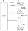
도 4는 무선전력전송 시스템의 동작 흐름도로써, 무선 전력 송신 장치의 동작 상태를 중심으로 한 동작 흐름도이다.4 is a flowchart illustrating an operation of the wireless power transmission system, and is a flowchart illustrating an operation of the wireless power transmission apparatus.
도 4를 참조하면, 본 발명의 실시 예에 따른 송신기 1000은 대기(Standby) 상태 401, 디지털 핑(Digital ping) 상태 403, 인증(Identification) 상태 405, 전력 전달(Power Transfer) 상태 407 및 충전 종료(End of Charge; EOC) 상태 409를 가질 수 있다.4, a
[대기 상태 401][Standby state 401]
송신기 1000에 외부로부터 전원이 인가되어 송신기 1000이 시동되는 경우, 송신기 1000은 대기 상태가 될 수 있다. 대기 상태에 있는 송신기 1000은 충전 영역에 배치된 객체(object)(예를 들어 수신기 2000이나 금속성 이물질(foreign object; FO))의 존재 여부를 검출할 수 있다.When power is externally applied to the
송신기 1000이 충전 영역에 객체의 존재를 검출하는 방법으로는 자속의 변화, 객체와 송신부 1000 사이의 커패시턴스의 변화나 인덕턴스의 변화 또는 공진 주파수 쉬프트(freqency shift)를 모니터링 함으로써 객체를 검출할 수 있으나 이에 한정되는 것은 아니다.As a method of detecting the presence of an object in the charging area, the
송신기 1000이 충전 영역 내의 수신기 2000인 객체를 검출하면 다음 단계인 디지털 핑 상태로 넘어갈 수 있다.When the
[디지털 핑 상태 403][Digital Ping State 403]
디지털 핑 상태에서 송신기 1000은, 충전 가능한 수신기 2000과 접속되고, 송신기 1000으로부터 제공되는 무선 전력으로 충전이 가능한 유효한 수신기 2000인지 확인한다. 그리고 송신기 1000은, 충전 가능한 수신기 2000과 연결되기 위하여 기 설정된 주파수와 타이밍을 가진 디지털 핑을 생성하여 출력할 수 있다.In the digital ping state, the
만약 디지털 핑을 위한 충분한 전력 신호를 수신기 2000으로 전달되면 수신기 2000은 통신 프로토콜에 따라 상기 전력 신호를 변조함으로써 상기 디지털 핑에 대해 응답할 수 있다. 그리고 만약 송신기 1000이 수신기 2000으로부터 유효한 신호를 수신하면 전력 신호를 제거하지 않은 상태로 인증 상태로 넘어갈 수 있다. 그리고 만약 수신기 2000으로부터 충전 종료(EOC) 요청이 수신되는 경우 송신기 1000은 충전 종료 상태로 넘어갈 수 있다.If a sufficient power signal for the digital ping is passed to the
또한 유효한 수신기 2000이 검출되지 않는 경우나 디지털 핑에 대한 객체의 응답 시간이 기 설정된 시간을 초과한 경우 송신기 1000은 전력 신호를 제거하여 대기 상태로 되돌아 갈 수 있다.Also, if the
[인증 상태 405][Authentication status 405]
송신기 1000의 디지털 핑에 따른 수신기 2000의 응답이 완료되면 송신기 1000은 송신기 1000의 인증 정보를 수신기 2000에 전송하여 송신기 1000 및 수신기 2000 상호간의 호환성을 확인할 수 있다. 그리고 호환성이 확인되면 수신기 2000은 인증 정보를 송신기 1000에 전송할 수 있다. 그리고 송신기 1000은 수신기 2000의 인증 정보를 확인할 수 있다.When the response of the
송신기 1000은 상호간의 인증이 완료되면 전력 전송 상태로 넘어가고, 인증이 실패 하였거나, 기 설정된 인증 시간을 초과한 경우에는 대기 상태로 되돌아 갈 수 있다.When the mutual authentication is completed, the
[전력 전송 상태 407][Power transmission state 407]
송신기 1000의 통신 및 제어기 1500은, 수신기 2000으로부터 제공받은 제어 데이터를 기초하여 송신기 1000을 제어함으로써 수신기 2000에 충전 전력을 제공할 수 있다. The communication and
나아가 송신기 1000은, 적절한 동작 범위를 벗어나지 않았는지 또는 FOD(foreign object detection)에 따른 안정성이 문제되지 않는지 검증할 수 있다. Further, the
또한 송신기 1000은, 수신기 2000으부터 충전 종료 요청 신호를 수신하거나, 기 설정된 한계 온도치를 초과하는 경우, 송신기 1000은 전력 전송을 중단할 수 있고 충전 종료 상태로 넘어갈 수 있다.Also, if the
또한 전력을 전송하기 적당하지 않은 상황으로 변한 경우, 전력 신호는 제거되고 대기 상태로 되돌아 갈 수 있다. 그리고 수신기 2000이 제거된 후 다시 수신기 2000이 충전 영역에 들어오면 전술한 사이클이 다시 진행할 수 있다.In addition, when the situation becomes unsuitable for transmitting power, the power signal can be removed and returned to the standby state. If the
또한 수신기 2000의 부하 2400의 충전 상태에서 따라서 다시 인증 상태로 돌아가 부하 2400의 상태 정보를 기초로 조절된 충전 전력을 수신기 2000에 제공할 수 있다.In addition, in the charging state of the
[충전 종료 상태 409][Charge termination state 409]
송신기 1000은 수신기 2000으로부터 충전이 완료 되었다는 정보를 수신하거나, 수신기 2000이 기 설정된 온도 이상으로 상승했다는 정보를 수신하는 경우 충전 종료 상태로 넘어갈 수 있다.The
송신기 1000이 수신기 2000으로부터 충전 완료 정보를 수신한 경우 송신기 1000은 전력 전송을 중단할 수 있고, 일정 시간 동안 대기할 수 있다. 그리고 일정 시간이 경과된 후 송신기 1000은 충전 영역에 배치된 수신기 2000과 연결되기 위하여 디지털 핑 상태로 진입할 수 있다.When the
그리고 송신기 1000이 수신기 2000으로부터 기 설정된 온도를 초과했다는 정보를 수신한 경우, 일정 시간 동안 대기할 수 있다. 그리고 일정 시간 경과 후 송신기 1000은 충전 영역에 배치된 수신기 2000과 접속되기 위하여 디지털 핑 상태로 진입 할 수 있다.If the
또한 송신기 1000은 일정 시간 동안 충전 영역에서 수신기 2000이 제거되었는지 모니터링 할 수 있고, 수신기 2000이 충전 영역으로부터 제거되면 대기 상태로 되돌아 갈 수 있다.The
도 5는 종래 기술에 따른 신발 끈을 묶는 동작을 도시한다.Fig. 5 shows the operation of tying the shoelace according to the prior art.
도 5를 참고하면, 일반적으로 신발의 사용자는 신발 끈을 직접 손으로 묶거나 풀 수 있다. 본 발명은 상기 신발 끈을 무선 전력 및 상기 무선 전력을 동력원으로 사용하는 모터를 이용하여 자동으로 묶거나 풀 수 있는 장치 및 방법을 제공하고자 한다.5, a user of a shoe generally can manually tie or loosen a shoelace. An object of the present invention is to provide an apparatus and method for automatically tying or loosening the shoelace using a wireless power and a motor using the wireless power as a power source.
도 6은 본 발명의 실시 예에 따른 무선 전력 송신기 및 무선 전력 수신기의 구조를 도시한다.6 illustrates a structure of a wireless power transmitter and a wireless power receiver according to an embodiment of the present invention.
도 6을 참고하면, 무선 전력 송신기 1000은 송신 코일 1300, 송신기 회로 1600을 포함할 수 있다. 송신 코일 1100은 수신기 2000으로 교류 전력을 무선으로 송신할 수 있다. 송신기 회로 1600은 도 2a 또는 도 2b에 도시된 인버터 1100, 코일 선택기 1200, 전류 감지기 1400, 제어 및 통신기 1500 중 적어도 하나를 포함할 수 있다.6, the
수신기 2000은 수신 코일 2100, 배터리 2400, 수신기 회로 2700, 모터 2800을 포함할 수 있다. 수신기 회로 2700은 도 4a 또는 도 4b에 도시된 정류 회로 2200, 제어 및 통신기 2300, 통신 변조기 2500, 출력 해제기 2600 중 적어도 하나를 포함할 수 있다.The
본 발명의 실시 예에 따른 수신 코일 2100은 송신 코일 1300으로부터 무선으로 교류 전력을 수신할 수 있다. 모터 2800은 상기 교류 전력에 기초하여 동작할 수 있다. 수신기 2000은 제1 센서(sensor) 2910을 더 포함할 수 있다. 제1 센서 2910은 사용자로부터 제어 신호를 입력받을 수 있다. 제어 및 통신기 2300은 제1 센서 2910을 통해 사용자로부터의 제어 신호를 확인하고, 상기 제어 신호에 기초하여 모터 2800을 제어할 수 있다. 본 발명의 다른 실시 예에 따라 수신기 2000은 제2 센서 2920 및 제3 센서 2930을 더 포함할 수 있다. 본 발명의 다양한 실시 예에 따라 제1 센서 2910, 제2 센서 2920, 제3 센서 2930은 각각 압전 센서 또는 터치 센서 또는 복수개의 입력 버튼(button)들을 포함하는 버튼일 수 있다.The receiving
본 발명의 실시 예에 따른 수신기 2000은 신발에 포함되는 장치일 수 있다. 이때, 모터 2800의 회전축에는 기어가 연결되고, 상기 기어는 상기 신발의 신발끈이 조여지거나 풀려지도록 제어할 수 있다. 예를 들어, 제어 및 통신기 2300은 제1 센서 2910을 통해 사용자로부터의 제어 신호를 확인할 수 있다. 제어 및 통신기 2300은 상기 제어 신호에 기초하여 상기 신발 끈이 조여지거나 또는 풀려지도록 모터 2800의 회전 방향을 제어할 수 있다.The
본 발명의 다른 실시 예에 따라, 제어 및 통신기 2300은 제2 센서 2920 및 제3 센서 2930을 통해 입력되는 신호에 기초하여 모터 2800을 제어할 수 있다. 예를 들어, 제2 센서 2920은 상기 신발의 앞 축에 배치될 수 있다. 또한, 제3 센서 2930은 상기 신발의 뒷 축에 배치될 수 있다. 이때, 상기 신발의 사용자가 앞 축에 압력을 가하여 제2 센서 2920이 상기 압력을 인지할 경우, 제어 및 통신기 2300은 모터 2800을 제어하여 신발 끈이 조여지도록 제어할 수 있다. 또한, 상기 신발의 사용자가 뒷 축에 압력을 가하여 제3 센서 2930이 상기 압력을 인지할 경우, 제어 및 통신기 2300은 모터 2800을 제어하여 신발 끈이 풀리도록 제어할 수 있다. 무선 전력 송신기 1000은, 상기 신발의 케이스(case)에 포함되는 장치일 수 있다.According to another embodiment of the present invention, the control and
도 7은 본 발명의 실시 예에 따른 무선 전력 송신기의 충전 동작 순서도이다.7 is a flowchart of a charging operation of a wireless power transmitter according to an embodiment of the present invention.
도 7을 참고하면, 무선 전력 송신기 1000은 무선 전력을 무선 전력 수신기 2000으로 송신할지 여부가 결정되지 않은 대기 상태에 있을 수 있다(S701 단계). 무선 전력 송신기 1000은 무선 전력 송신기 1000의 충전 패드에 물체가 놓였는지 여부를 확인할 수 있다(S703 단계). 상기 충전 패드는 무선 전력 송신기 1000의 송신 코일 1300이 배치되는 지점을 의미할 수 있다. 예를 들어, 상기 충전 패드는 무선 전력 송신기 1000의 상면 또는 하면 또는 측면에 위치할 수 있다. 무선 전력 송신기 1000은 제어 및 통신부 1500을 통해 디지털 핑 신호를 송신하고, 상기 디지털 핑 신호에 대한 응답 신호를 수신할 수 있다. 무선 전력 송신기 1000은 제어 및 통신부 1500을 통해 상기 응답 신호 기초하여 상기 물체가 놓였는지 여부를 확인할 수 있다. 예를 들어, 무선 전력 송신기 1000은 상기 응답 신호가 수신될 경우, 제어 및 통신부 1500을 통해 상기 물체가 놓였다고 판단할 수 있다.Referring to FIG. 7, the
무선 전력 송신기 1000은 상기 물체가 놓였을 경우, 제어 및 통신부 1500을 통해 상기 물체가 사용자 신발인지 여부를 확인할 수 있다(S705 단계). 무선 전력 송신기 1000은 제어 및 통신부 1500을 통해 상기 물체로 인증 정보를 요청하는 메시지를 송신할 수 있다. 무선 전력 송신기 1000은 제어 및 통신부 1500을 통해 상기 물체로부터 상기 인증 정보를 수신할 수 있다. 무선 전력 송신기 1000은 제어 및 통신부 1500을 통해 상기 인증 정보에 기초하여 상기 물체가 상기 사용자 신발에 포함된 무선 전력 수신기 2000임을 확인할 수 있다.In step S705, the
무선 전력 송신기 1000은 상기 물체가 상기 사용자 신발에 포함된 무선 전력 수신기 2000일 경우, 무선 충전을 진행할 수 있다(S707 단계). 예를 들어, 무선 전력 송신기 1000은 송신 코일 1300을 통해 상기 무선 전력 수신기 2000으로 무선 전력을 송신할 수 있다.The
무선 전력 송신기 1000은 무선 전력 수신기 2000의 배터리 2400의 충전이 완료됨을 확인할 수 있다(S709 단계). 예를 들어, 무선 전력 송신기 1000은 제어 및 통신부 1500을 통해 무선 전력 수신기 2000으로부터 배터리 2400의 충전이 완료되었음을 알리는 메시지를 수신할 수 있다.The
도 8은 본 발명의 실시 예에 따른 무선 전력 수신기의 사용자 제어 신호에 따른 동작 순서도이다.8 is a flowchart illustrating an operation according to a user control signal of a wireless power receiver according to an embodiment of the present invention.
도 8을 참고하면, 무선 전력 수신기 2000은 사용자로부터의 제어 신호를 수신하기 위한 대기 상태일 수 있다(S801 단계). 무선 전력 수신기 2000은 사용자 버튼의 눌림을 확인할 수 있다(S803 단계). 본 발명의 실시 예에 따라 무선 전력 수신기 2000은 사용자로부터의 입력을 수신하는 제1 센서 2910을 포함할 수 있다. 예를 들어, 제1 센서 2910은 사용자로부터 신발 끈을 조일 것을 명령하는 신호를 수신할 수 있다(S805 단계). 본 발명의 실시 예에 따른 무선 전력 수신기 2000은 모터 2800을 통해 상기 신발 끈이 조여지거나 풀려지도록 제어할 수 있다. 모터 2800의 회전 축은 상기 신발 끈에 연결되는 기어를 포함할 수 있다.Referring to FIG. 8, the
무선 전력 수신기 2000은 제1 센서 2910을 통해 감지한 신발 끈을 조일 것을 명령하는 제어 신호에 기초하여 상기 신발 끈을 조일 수 있다(S807 단계). 무선 전력 수신기 2000은 상기 제어 신호가 입력되면, 제어 및 통신부 1500을 통해 신발 끈이 조여지도록 모터 2800의 회전 축에 연결된 기어의 회전 방향을 제어할 수 있다.The
무선 전력 수신기 2000은 제1 센서 2910을 통해 사용자로부터 상기 신발 끈을 풀 것을 명령하는 신호를 수신할 수 있다(S809 단계). 무선 전력 수신기 2000은 제1 센서 2910을 통해 신발 끈을 풀 것을 명령하는 신호에 기초하여 상기 신발 끈을 풀 수 있다(S811 단계). 무선 전력 수신기 2000은 제어 및 통신부 1500을 통해 신발 끈이 풀어지도록 모터 2800의 회전 축에 연결된 기어의 회전 방향을 제어할 수 있다.The
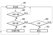
도 9는 본 발명의 실시 예에 따른 무선 전력 수신기의 충전 동작 순서도이다.9 is a flowchart of a charging operation of a wireless power receiver according to an embodiment of the present invention.
도 9를 참고하면, 무선 전력 수신기 2000은 대기 상태에 있을 수 있다(S901 단계). 무선 전력 수신기 2000은 사용자를 식별할 수 있다(S903 단계). 예를 들어, 무선 전력 수신기 2000은 무선 전력 송신기 1000으로부터 수신한 디지털 핑 신호에 기초하여 상기 사용자를 식별할 수 있다. 무선 전력 수신기 2000은 제어 및 통신부 2300을 통해 무선 전력 송신기 1000로부터 디지털 핑 신호를 수신할 수 있다. 무선 전력 수신기 2000은 제어 및 통신부 2300을 통해 상기 디지털 핑 신호에 대한 응답 신호를 무선 전력 송신기 1000으로 송신할 수 있다.Referring to FIG. 9, the
무선 전력 수신기 2000은 충전이 진행되는지 여부를 확인할 수 있다(S905 단계). 예를 들어, 무선 전력 수신기 2000은 제어 및 통신부 2300을 통해 무선 전력 송신기 1000으로부터 인증 정보를 요청하는 메시지를 수신할 수 있다. 무선 전력 수신기 2000은 제어 및 통신부 2300을 통해 무선 전력 수신기 2000이 신발에 포함되는 장치임을 알리는 메시지를 무선 전력 송신기 1000으로 송신할 수 있다.The
무선 전력 수신기 2000은 충전을 진행할 수 있다(S907 단계). 무선 전력 수신기 2000은 수신 코일 2100을 통해 무선 전력 송신기 1000으로부터 교류 전력을 수신할 수 있다.The
무선 전력 수신기 2000은 충전이 진행되지 않을 경우, 오류 여부를 확인할 수 있다(S909 단계). 무선 전력 수신기 2000은 오류가 발생한 경우, 충전을 재시도할 수 있다(S911 단계). 무선 전력 수신기 2000은, 오류가 아닌 경우, 대기 상태로 돌아갈 수 있다.If the charging of the
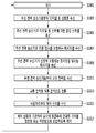
도 10은 본 발명의 실시 예에 따른 무선 전력 수신기의 동작 순서도이다.10 is an operational flowchart of a wireless power receiver according to an embodiment of the present invention.
도 10을 참고하면, 무선 전력 수신기 2000은 제어 및 통신부 2300을 통해 무선 전력 송신기 1000로부터 디지털 핑 신호를 수신할 수 있다(S1001 단계). 무선 전력 수신기 2000은 제어 및 통신부 2300을 통해 상기 디지털 핑 신호에 대한 응답 신호를 무선 전력 송신기 1000으로 송신할 수 있다(S1003 단계).Referring to FIG. 10, the
무선 전력 수신기 2000은 제어 및 통신부 2300을 통해 무선 전력 송신기 1000으로부터 인증 정보를 요청하는 메시지를 수신할 수 있다(S1007 단계). 무선 전력 수신기 2000은 제어 및 통신부 2300을 통해 무선 전력 수신기 2000이 신발에 포함되는 장치임을 알리는 메시지를 무선 전력 송신기 1000으로 송신할 수 있다(S1009 단계). 무선 전력 수신기 2000은 수신 코일 2100을 통해 무선 전력 송신기 1000으로부터 교류 전력을 수신할 수 있다(S1011 단계).The
무선 전력 수신기 2000은 상기 교류 전력을 직류 전력으로 정류할 수 있다(S1013 단계). 예를 들어, 무선 전력 수신기 2000의 정류 회로기 2200은 수신 코일 2100을 통해 수신한 상기 교류 전력을 직류 전력으로 정류할 수 있다.The
무선 전력 수신기 2000은 사용자로부터 제어 신호를 수신할 수 있다(S1015 단계). 본 발명의 실시 예에 따라 무선 전력 수신기 2000은 상기 사용자로부터 제어 신호를 수신하기 위한 제1 센서 2910을 포함할 수 있다. 제1 센서 2910은 복수개의 입력 버튼들 또는 터치 패드일 수 있다. 무선 전력 수신기 2000은 제1 센서 2910을 통해 상기 사용자로부터의 제어 신호를 수신할 수 있다. 본 발명의 실시 예에 따라 무선 전력 수신기 2000은 상기 직류 전력을 통해 구동되는 모터 2800을 포함할 수 있다.The
무선 전력 수신기 2000은 상기 제어 신호에 기초하여 모터 2800의 회전축에 연결된 기어를 정방향 또는 역방향으로 회전하도록 제어할 수 있다(S1017 단계). 예를 들어, 무선 전력 수신기 2000은 제어 및 통신부 2300을 통해 상기 모터 2800을 제어할 수 있다.The
본 발명의 실시 예에 따라 무선 전력 수신기 2000은 특정 물체를 수용하는 수용부를 포함할 수 있다. 무선 전력 수신기 2000은 상기 수용부의 개방 또는 폐쇄를 위한 로프를 더 포함할 수 있다. 상기 로프의 일부는, 상기 수용부의 일부에 고정될 수 있다. 상기 로프의 다른 일부는, 상기 모터 2800의 기어에 연결될 수 있다. 제어 및 통신부 2300은 상기 제어 신호에 기초하여 상기 로프가 상기 수용부를 개방 또는 폐쇄하도록 모터 2800을 제어할 수 있다.In accordance with an embodiment of the present invention, the
상기 센서는 상기 사용자의 터치 신호를 수신하는 제1 센서 및 제2 센서를 포함할 수 있다. 상기 제어 및 통신부 2300은 상기 제1 센서에 상기 터치 신호가 감지될 경우, 상기 로프가 상기 수용부를 폐쇄하도록 모터 2800의 기어가 정방향으로 회전하도록 제어할 수 있다. 상기 제어 및 통신부 2300은 상기 제2 센서에 상기 터치 신호가 감지될 경우, 상기 로프가 상기 수용부를 개방하도록 모터 2800의 기어가 역방향으로 회전하도록 제어할 수 있다.The sensor may include a first sensor and a second sensor for receiving the touch signal of the user. The control and
본 발명의 다른 실시 예에 따라, 무선 전력 수신기 2000은 무선 전력 수신기 2000의 전면에 배치되는 제2 센서 2920 및 무선 전력 수신기 2000의 후면에 배치되는 제3 센서 2930을 포함할 수 있다. 제어 및 통신부 2300은 제2 센서 2920에 압력이 인지될 경우, 상기 로프가 상기 수용부를 폐쇄하도록 모터 2800의 기어가 정방향으로 회전하도록 제어할 수 있다. 제어 및 통신부 2300은 제3 센서 2930에 압력이 인지될 경우, 상기 로프가 상기 수용부를 개방하도록 모터 2800의 기어가 역방향으로 회전하도록 제어할 수 있다.In accordance with another embodiment of the present invention, the
제어 및 통신부 2300은 상기 무선 전력이 수신될 경우, 상기 제어 신호가 수신되지 않아도 상기 모터의 기어가 정방향 또는 역방향으로 회전하도록 제어할 수 있다. 제어 및 통신부 2300은 상기 수용부의 개방 또는 폐쇄 상태를 확인할 수 있다. 제어 및 통신부 2300은 상기 수용부가 개방되었을 경우, 상기 로프가 상기 수용부를 폐쇄하도록 모터 2800의 기어가 정방향으로 회전하도로 제어할 수 있다. 제어 및 통신부 2300은 상기 수용부가 폐쇄되었을 경우, 상기 로프가 상기 수용부를 개방하도록 모터 2800의 기어가 역방향으로 회전하도록 제어할 수 있다.When the radio power is received, the control and
본 발명의 다른 실시 예에 따라, 수신 코일 2100은 무선 전력 수신기 2000의 후면에 배치될 수 있다. 본 발명의 또 다른 실시 예에 따라, 수신 코일 2100은 무선 전력 수신기 2000의 중앙에 배치되는 내부 코일 및 무선 전력 수신기 2000의 외곽에서 상기 내부 코일을 둘러싸는 형태로 배치되는 외부 코일을 포함할 수 있다. 상기 내부 코일 및 상기 외부 코일은 상호 연결될 수 있다. 무선 전력 수신기 2000은 상기 직류 전력으로 충전되는 배터리 2400을 포함할 수 있다. 모터 2800은 배터리 2400으로부터 공급되는 전력을 이용하여 구동될 수 있다.In accordance with another embodiment of the present invention, the receive
본 발명의 실시 예에 따라 무선 전력 수신기 2000은 신발에 포함될 수 있다. 이때, 상기 로프는 상기 신발의 신발끈일 수 있다. 또한, 수신 코일 2100은 플렉서블 코일일 수 있다.In accordance with an embodiment of the present invention, a
도 11은 본 발명의 실시 예에 따른 무선 전력 송신기의 동작 순서도이다.11 is an operation flowchart of a wireless power transmitter according to an embodiment of the present invention.
무선 전력 송신기 1000은 무선 전력 수신기 2000으로 무선 전력을 송신할지 여부를 대기할 수 있다(S1101 단계). 무선 전력 송신기 1000은 제어 및 통신부 1500을 통해 무선 전력 수신기 200으로 디지털 핑 신호를 송신할 수 있다(S1103 단계). 무선 전력 송신기 1000은 제어 및 통신부 1500을 통해 상기 디지털 핑 신호에 대한 응답 신호를 수신할 수 있다(S1105 단계).The
무선 전력 송신기 1000은 제어 및 통신부 1500을 통해 무선 전력 수신기 2000으로 인증 정보를 요청하는 메시지를 송신할 수 있다(S1107 단계). 무선 전력 송신기 1000은 제어 및 통신부 1500을 통해 무선 전력 수신기 2000으로부터 상기 인증 정보를 수신할 수 있다(S1109 단계).The
무선 전력 송신기 2000은 제어 및 통신부 1500을 통해 상기 인증 정보에 기초하여 무선 전력 수신기 2000이 신발에 포함되는 되는 무선 전력 수신기인지 여부를 확인할 수 있다(S1111 단계). 무선 전력 송신기 1000은 무선 전력 수신기 2000이 신발에 포함되는 무선 전력 수신기일 경우, 송신 코일 1300을 통해 상기 무선 전력을 무선 전력 수신기 2000으로 송신할 수 있다(S1115 단계).The
1100 송신측 교류/직류 변환기
1110 정류기
1120 송신측 직류/직류 변환기
1200 송신측 직류/교류 변환기
1300 송신측 임피던스 매칭기
1400 송신 코일
1500 송신측 통신 및 제어기
1510 송신측 제어기
1520 송신측 통신기
2000 수신부
2100 수신측 코일
2200 수신측 임피던스 매칭기
2300 수신측 교류/직류 변환기
2400 수신측 직류/직류 변환기
2500 부하
2600 수신측 통신 및 제어기
2610 수신측 제어기
2620 수신측 통신기1100 Transmitter AC / DC converter
1110 Rectifier
1120 Transmitter DC / DC converter
1200 Transmitter DC / AC Converter
1300 Transmitter impedance matcher
1400 transmission coil
1500 Transmitter communication and controller
1510 transmission side controller
1520 transmitting side communicator
2000 receiver
2100 Receiving side coil
2200 Receiver side impedance matching machine
2300 Receiver side AC / DC converter
2400 Receiver side DC / DC converter
2500 load
2600 Receive communication and controller
2610 Receive-side controller
2620 Receiver communication device
Claims (15)
상기 교류 전력을 직류 전력으로 정류하는 정류기;
상기 직류 전력을 통해 구동되는 모터;
사용자로부터 제어 신호를 수신하는 센서; 및
상기 제어 신호에 기초하여 상기 모터의 회전축에 연결된 기어를 정방향 또는 역방향으로 회전하도록 제어하는 제어기를 포함하는 무선 전력 수신기.A receiving coil for receiving AC power from the wireless power receiver wirelessly;
A rectifier for rectifying the AC power to DC power;
A motor driven by the DC power;
A sensor for receiving a control signal from a user; And
And a controller for controlling to rotate the gear connected to the rotation axis of the motor in a forward or reverse direction based on the control signal.
특정 물체를 수용하는 수용부;
상기 수용부의 개방 또는 폐쇄를 위한 로프를 더 포함하고,
상기 로프의 일부는, 상기 수용부의 일부에 고정되고, 상기 로프의 다른 일부는, 상기 기어에 연결되고,
상기 제어기는, 상기 제어 신호에 기초하여 상기 로프가 상기 수용부를 개방 또는 폐쇄하도록 상기 모터를 제어하는 무선 전력 수신기.The method according to claim 1,
A receiving portion for receiving a specific object;
Further comprising a rope for opening or closing said receiving portion,
A part of the rope is fixed to a part of the receiving part, and another part of the rope is connected to the gear,
And the controller controls the motor to open or close the receptacle based on the control signal.
상기 센서는, 상기 사용자의 터치 신호를 수신하는 제1 센서 및 제2 센서를 포함하고,
상기 제어기는, 상기 제1 센서에 상기 터치 신호가 감지될 경우, 상기 로프가 상기 수용부를 폐쇄하도록 상기 모터의 기어가 정방향으로 회전하도록 제어하고, 상기 제2 센서에 상기 터치 신호가 감지될 경우, 상기 로프가 상기 수용부를 개방하도록 상기 모터의 기어가 역방향으로 회전하도록 제어하는 무선 전력 수신기.3. The method of claim 2,
Wherein the sensor includes a first sensor and a second sensor for receiving the touch signal of the user,
Wherein the controller controls the gear of the motor to rotate in the forward direction so that the rope closes the receiving portion when the touch signal is sensed by the first sensor, and when the touch signal is sensed by the second sensor, And controls the gear of the motor to rotate in the reverse direction so that the rope opens the receiving portion.
상기 센서는, 상기 무선 전력 수신기의 전면에 배치되는 전면 센서 및 상기 무선 전력 수신기의 후면에 배치되는 후면 센서를 포함하고,
상기 제어기는, 상기 전면 센서에 압력이 인지될 경우, 상기 로프가 상기 수용부를 폐쇄하도록 상기 모터의 기어가 정방향으로 회전하도록 제어하고, 상기 후면 센서에 압력이 인지될 경우, 상기 로프가 상기 수용부를 개방하도록 상기 모터의 기어가 역방향으로 회전하도록 제어하는 무선 전력 수신기.3. The method of claim 2,
Wherein the sensor includes a front sensor disposed on a front surface of the wireless power receiver and a rear surface sensor disposed on a rear surface of the wireless power receiver,
Wherein the controller controls the gears of the motor to rotate in the forward direction so that the rope closes the receiving portion when pressure is recognized on the front sensor and when the pressure is recognized on the rear sensor, And controls the gear of the motor to rotate in the reverse direction so as to open.
상기 제어기는, 상기 무선 전력이 수신될 경우, 상기 제어 신호가 수신되지 않아도 상기 모터의 기어가 정방향 또는 역방향으로 회전하도록 제어하는 무선 전력 수신기.The method according to claim 1,
Wherein the controller controls the gear of the motor to rotate in a forward or reverse direction when the radio power is received, even if the control signal is not received.
상기 제어기는, 상기 수용부의 개방 또는 폐쇄 상태를 확인하고, 상기 수용부가 개방되었을 경우, 상기 로프가 상기 수용부를 폐쇄하도록 상기 모터의 기어가 정방향으로 회전하도로 제어하고, 상기 수용부가 폐쇄되었을 경우, 상기 로프가 상기 수용부를 개방하도록 상기 모터의 기어가 역방향으로 회전하도록 제어하는 무선 전력 수신기.6. The method of claim 5,
Wherein the controller controls the opening or closing state of the accommodating portion and controls the gear of the motor to rotate in the forward direction so that the rope closes the accommodating portion when the accommodating portion is opened, And controls the gear of the motor to rotate in the reverse direction so that the rope opens the receiving portion.
상기 수신 코일은, 상기 무선 전력 수신기의 후면에 배치되는 무선 전력 수신기.The method according to claim 1,
Wherein the receive coil is disposed on a back surface of the wireless power receiver.
상기 수신 코일은, 상기 무선 전력 수신기의 중앙에 배치되는 내부 코일 및 상기 무선 전력 수신기의 외곽에서 상기 내부 코일을 둘러싸는 형태로 배치되는 외부 코일을 포함하고, 상기 내부 코일 및 상기 외부 코일을 연결되는 무선 전력 수신기.The method according to claim 1,
Wherein the receiving coil includes an inner coil disposed in the center of the wireless power receiver and an outer coil disposed in the form of surrounding the inner coil at an outer periphery of the wireless power receiver, Wireless power receiver.
상기 직류 전력으로 충전되는 배터리를 더 포함하고,
상기 모터는, 상기 배터리로부터 공급되는 전력을 이용하여 구동되는 무선 전력 수신기.The method according to claim 1,
Further comprising a battery charged with the direct current power,
Wherein the motor is driven using power supplied from the battery.
상기 무선 전력 송신기로 상기 무선 전력 송신기의 식별 정보를 송신하고, 상기 무선 전력 송신기로부터 응답 신호를 수신하는 송수신기를 더 포함하는 무선 전력 수신기.The method according to claim 1,
Further comprising a transceiver for transmitting identification information of the wireless power transmitter to the wireless power transmitter and receiving a response signal from the wireless power transmitter.
상기 무선 전력 수신기는 신발에 포함되고,
상기 로프는, 상기 신발의 신발끈인 무선 전력 수신기.3. The method of claim 2,
Wherein the wireless power receiver is included in a shoe,
Wherein the rope is a shoelace of the shoe.
상기 수신 코일은, 플렉서블(flexible) 코일인 무선 전력 수신기.The method according to claim 1,
Wherein the reception coil is a flexible coil.
상기 식별 정보에 기초하여 상기 무선 전력 수신기가 신발에 포함되는 무선 전력 수신기인지 여부를 확인하는 제어기; 및
상기 무선 전력 수신기가 상기 신발에 포함되는 무선 전력일 경우, 상기 무선 전력 수신기로 무선으로 교류 전력을 송신하는 송신 코일을 포함하는 무선 전력 송신기.A transceiver for receiving identification information from a wireless power receiver;
A controller for determining whether the wireless power receiver is a wireless power receiver included in the shoe based on the identification information; And
And a transmit coil that wirelessly transmits AC power to the wireless power receiver when the wireless power receiver is wireless power included in the shoe.
상기 무선 전력 송신기로부터 인증 정보를 요청하는 메시지를 수신하고, 무선 전력 수신기가 신발에 포함되는 장치임을 알리는 메시지를 송신하는 인증 단계;
상기 무선 전력 송신기로부터 교류 전력을 수신하는 단계;
상기 교류 전력을 직류 전력으로 정류하는 단계;
사용자로부터 제어 신호를 수신하는 단계; 및
상기 제어 신호에 기초하여 상기 무선 전력 수신기의 모터의 회전축에 연결된 기어를 정방향 또는 역방향으로 회전하도록 제어하는 단계를 포함하는 무선 전력 수신기의 동작 방법.Receiving a digital zip signal from a wireless power transmitter and transmitting a response signal to the wireless power transmitter to the digital zip signal;
An authentication step of receiving a message requesting authentication information from the wireless power transmitter and transmitting a message indicating that the wireless power receiver is a device included in the shoe;
Receiving AC power from the wireless power transmitter;
Rectifying the AC power to DC power;
Receiving a control signal from a user; And
And controlling the gear connected to the rotation axis of the motor of the wireless power receiver to rotate in a forward or reverse direction based on the control signal.
상기 무선 전력 수신기로 디지털 핑 신호를 송신하고, 상기 디지털 핑 신호에 대한 응답 신호를 수신하는 디지털 핑 단계;
상기 무선 전력 수신기로 인증 정보를 요청하는 메시지를 송신하고, 상기 인증 정보를 수신하는 인증 단계; 및
상기 무선 전력 수신기로 상기 무선 전력을 전송하는 전력 전송 단계;를 포함하고,
상기 인증 단계는, 상기 인증 정보에 기초하여 상기 무선 전력 수신기가 신발에 포함되는 되는 무선 전력 수신기인지 여부를 확인하는 단계를 포함하고,
상기 전력 전송 단계는, 상기 무선 전력 수신기가 신발에 포함되는 무선 전력 수신기일 경우, 상기 무선 전력을 전송하는 단계를 포함하는 무선 전력 송신기의 동작 방법.Waiting for transmission of wireless power to the wireless power receiver;
A digital paging step of transmitting a digital ping signal to the wireless power receiver and receiving a response signal to the digital ping signal;
An authentication step of transmitting a message requesting authentication information to the wireless power receiver and receiving the authentication information; And
And a power transmission step of transmitting the radio power to the radio power receiver,
Wherein the authenticating includes determining whether the wireless power receiver is a wireless power receiver included in the shoe based on the authentication information,
Wherein the transmitting power comprises transmitting the wireless power when the wireless power receiver is a wireless power receiver included in the shoe.
Priority Applications (2)
| Application Number | Priority Date | Filing Date | Title |
|---|---|---|---|
| KR1020160035024A KR20170110802A (en) | 2016-03-24 | 2016-03-24 | A wireless power receiver and thereof operation method |
| PCT/KR2017/003004 WO2017164612A1 (en) | 2016-03-24 | 2017-03-21 | Wireless power receiver and operation method therefor |
Applications Claiming Priority (1)
| Application Number | Priority Date | Filing Date | Title |
|---|---|---|---|
| KR1020160035024A KR20170110802A (en) | 2016-03-24 | 2016-03-24 | A wireless power receiver and thereof operation method |
Publications (1)
| Publication Number | Publication Date |
|---|---|
| KR20170110802A true KR20170110802A (en) | 2017-10-12 |
Family
ID=59899562
Family Applications (1)
| Application Number | Title | Priority Date | Filing Date |
|---|---|---|---|
| KR1020160035024A KR20170110802A (en) | 2016-03-24 | 2016-03-24 | A wireless power receiver and thereof operation method |
Country Status (2)
| Country | Link |
|---|---|
| KR (1) | KR20170110802A (en) |
| WO (1) | WO2017164612A1 (en) |
Cited By (1)
| Publication number | Priority date | Publication date | Assignee | Title |
|---|---|---|---|---|
| KR20240008035A (en) * | 2022-07-11 | 2024-01-18 | 한국전자기술연구원 | Power supply with alternative power source for smart insole |
Families Citing this family (10)
| Publication number | Priority date | Publication date | Assignee | Title |
|---|---|---|---|---|
| US11185130B2 (en) | 2015-10-07 | 2021-11-30 | Puma SE | Article of footwear having an automatic lacing system |
| US11103030B2 (en) | 2015-10-07 | 2021-08-31 | Puma SE | Article of footwear having an automatic lacing system |
| US11033079B2 (en) | 2015-10-07 | 2021-06-15 | Puma SE | Article of footwear having an automatic lacing system |
| JP7049992B2 (en) | 2015-12-02 | 2022-04-07 | プーマ エス イー | How to race shoes, especially sports shoes |
| US11439192B2 (en) | 2016-11-22 | 2022-09-13 | Puma SE | Method for putting on or taking off a piece of clothing or for closing, putting on, opening, or taking off a piece of luggage |
| CA3042721C (en) | 2016-11-22 | 2023-09-26 | Puma SE | Method for fastening a shoe, in particular a sports shoe, and shoe, in particular sports shoe |
| USD899053S1 (en) | 2019-01-30 | 2020-10-20 | Puma SE | Shoe |
| USD906657S1 (en) | 2019-01-30 | 2021-01-05 | Puma SE | Shoe tensioning device |
| USD889805S1 (en) | 2019-01-30 | 2020-07-14 | Puma SE | Shoe |
| US11484089B2 (en) | 2019-10-21 | 2022-11-01 | Puma SE | Article of footwear having an automatic lacing system with integrated sound damping |
Family Cites Families (5)
| Publication number | Priority date | Publication date | Assignee | Title |
|---|---|---|---|---|
| US8046937B2 (en) * | 2008-05-02 | 2011-11-01 | Nike, Inc. | Automatic lacing system |
| KR101815323B1 (en) * | 2011-09-08 | 2018-01-05 | 삼성전자주식회사 | Method and devices for transmitting signal from a plurality of wireless power receivers to wireless power provider |
| EP4327688A3 (en) * | 2012-08-31 | 2024-05-01 | Nike Innovate C.V. | Motorized tensioning system with sensors |
| KR102006027B1 (en) * | 2012-11-09 | 2019-07-31 | 지이 하이브리드 테크놀로지스, 엘엘씨 | Wireless chargeable shoes and wireless charger used therein |
| KR101588837B1 (en) * | 2014-03-17 | 2016-01-26 | 한솔테크닉스(주) | Heating shoes that radio charge is possible |
-
2016
- 2016-03-24 KR KR1020160035024A patent/KR20170110802A/en unknown
-
2017
- 2017-03-21 WO PCT/KR2017/003004 patent/WO2017164612A1/en active Application Filing
Cited By (1)
| Publication number | Priority date | Publication date | Assignee | Title |
|---|---|---|---|---|
| KR20240008035A (en) * | 2022-07-11 | 2024-01-18 | 한국전자기술연구원 | Power supply with alternative power source for smart insole |
Also Published As
| Publication number | Publication date |
|---|---|
| WO2017164612A1 (en) | 2017-09-28 |
Similar Documents
| Publication | Publication Date | Title |
|---|---|---|
| KR20170110802A (en) | A wireless power receiver and thereof operation method | |
| US10396599B2 (en) | Wireless power transmission apparatus and wireless power transmission method | |
| US20180241223A1 (en) | Wireless power transfer system and driving method therefor | |
| US9142999B2 (en) | Systems, methods, and apparatus for small device wireless charging modes | |
| US9191075B2 (en) | Wireless power control method, system, and apparatus utilizing a wakeup signal to prevent standby power consumption | |
| CN106920657B (en) | The coil device of wireless power transmission system | |
| EP3072215B1 (en) | Wireless charging apparatus and wireless charging method | |
| KR20160143044A (en) | Wireless Power Transfer System and Operating method thereof | |
| US20180316388A1 (en) | Wireless power transmitter, wireless power receiver, and wireless system, for transmitting and receiving wireless signal, and operating method therefor | |
| US20190027954A1 (en) | Wireless power transmitter and receiver | |
| US20180205268A1 (en) | Method for operating wireless power transmission device | |
| US20180226829A1 (en) | Wireless power transmission system, and operation method therefor | |
| CN106471709B (en) | Wireless power transmission system | |
| US20190222060A1 (en) | Wireless power transmitter and receiver | |
| US20190027968A1 (en) | Wireless power transmitter and receiver | |
| KR101996966B1 (en) | Wireless Power Transfer System and Operating method thereof | |
| KR20120052517A (en) | Wireless power transmission method, wireless power receiving method, wireless power transmission apparatus and wireless power receiving apparatus | |
| KR20170067169A (en) | Wireless apparatus and method for transmitting power | |
| KR20170139319A (en) | A wireless power transmitter and a wireless power receiver | |
| KR20170142678A (en) | A wireless power transmitter and a wireless power receiver | |
| KR20170137494A (en) | A wireless power transmitter | |
| KR20180021559A (en) | Wireless power transmitter | |
| KR20170005589A (en) | Apparatus for transmitting wireless power and system for transmitting wireless power | |
| KR20170082309A (en) | A wireless power transmitter and a wireless power receiver of wireless power transfer system | |
| KR20170082281A (en) | A wireless power transmitter and a wireless power receiver of wireless power transfer system |