KR20170110683A - Single-pass inkjet printer - Google Patents
Single-pass inkjet printer Download PDFInfo
- Publication number
- KR20170110683A KR20170110683A KR1020177024742A KR20177024742A KR20170110683A KR 20170110683 A KR20170110683 A KR 20170110683A KR 1020177024742 A KR1020177024742 A KR 1020177024742A KR 20177024742 A KR20177024742 A KR 20177024742A KR 20170110683 A KR20170110683 A KR 20170110683A
- Authority
- KR
- South Korea
- Prior art keywords
- doctor blade
- inkjet printer
- storage
- pass inkjet
- printhead
- Prior art date
Links
Images


Classifications
-
- B—PERFORMING OPERATIONS; TRANSPORTING
- B41—PRINTING; LINING MACHINES; TYPEWRITERS; STAMPS
- B41J—TYPEWRITERS; SELECTIVE PRINTING MECHANISMS, i.e. MECHANISMS PRINTING OTHERWISE THAN FROM A FORME; CORRECTION OF TYPOGRAPHICAL ERRORS
- B41J2/00—Typewriters or selective printing mechanisms characterised by the printing or marking process for which they are designed
- B41J2/005—Typewriters or selective printing mechanisms characterised by the printing or marking process for which they are designed characterised by bringing liquid or particles selectively into contact with a printing material
- B41J2/01—Ink jet
- B41J2/135—Nozzles
- B41J2/165—Preventing or detecting of nozzle clogging, e.g. cleaning, capping or moistening for nozzles
- B41J2/16517—Cleaning of print head nozzles
-
- B—PERFORMING OPERATIONS; TRANSPORTING
- B41—PRINTING; LINING MACHINES; TYPEWRITERS; STAMPS
- B41J—TYPEWRITERS; SELECTIVE PRINTING MECHANISMS, i.e. MECHANISMS PRINTING OTHERWISE THAN FROM A FORME; CORRECTION OF TYPOGRAPHICAL ERRORS
- B41J2/00—Typewriters or selective printing mechanisms characterised by the printing or marking process for which they are designed
- B41J2/005—Typewriters or selective printing mechanisms characterised by the printing or marking process for which they are designed characterised by bringing liquid or particles selectively into contact with a printing material
- B41J2/01—Ink jet
- B41J2/135—Nozzles
- B41J2/165—Preventing or detecting of nozzle clogging, e.g. cleaning, capping or moistening for nozzles
- B41J2/16505—Caps, spittoons or covers for cleaning or preventing drying out
- B41J2/16508—Caps, spittoons or covers for cleaning or preventing drying out connected with the printer frame
-
- B—PERFORMING OPERATIONS; TRANSPORTING
- B41—PRINTING; LINING MACHINES; TYPEWRITERS; STAMPS
- B41J—TYPEWRITERS; SELECTIVE PRINTING MECHANISMS, i.e. MECHANISMS PRINTING OTHERWISE THAN FROM A FORME; CORRECTION OF TYPOGRAPHICAL ERRORS
- B41J2/00—Typewriters or selective printing mechanisms characterised by the printing or marking process for which they are designed
- B41J2/005—Typewriters or selective printing mechanisms characterised by the printing or marking process for which they are designed characterised by bringing liquid or particles selectively into contact with a printing material
- B41J2/01—Ink jet
- B41J2/135—Nozzles
- B41J2/165—Preventing or detecting of nozzle clogging, e.g. cleaning, capping or moistening for nozzles
- B41J2/16517—Cleaning of print head nozzles
- B41J2/16535—Cleaning of print head nozzles using wiping constructions
- B41J2/16538—Cleaning of print head nozzles using wiping constructions with brushes or wiper blades perpendicular to the nozzle plate
-
- B—PERFORMING OPERATIONS; TRANSPORTING
- B41—PRINTING; LINING MACHINES; TYPEWRITERS; STAMPS
- B41J—TYPEWRITERS; SELECTIVE PRINTING MECHANISMS, i.e. MECHANISMS PRINTING OTHERWISE THAN FROM A FORME; CORRECTION OF TYPOGRAPHICAL ERRORS
- B41J2/00—Typewriters or selective printing mechanisms characterised by the printing or marking process for which they are designed
- B41J2/005—Typewriters or selective printing mechanisms characterised by the printing or marking process for which they are designed characterised by bringing liquid or particles selectively into contact with a printing material
- B41J2/01—Ink jet
- B41J2/135—Nozzles
- B41J2/165—Preventing or detecting of nozzle clogging, e.g. cleaning, capping or moistening for nozzles
- B41J2/16517—Cleaning of print head nozzles
- B41J2/16535—Cleaning of print head nozzles using wiping constructions
- B41J2/16544—Constructions for the positioning of wipers
-
- B—PERFORMING OPERATIONS; TRANSPORTING
- B41—PRINTING; LINING MACHINES; TYPEWRITERS; STAMPS
- B41J—TYPEWRITERS; SELECTIVE PRINTING MECHANISMS, i.e. MECHANISMS PRINTING OTHERWISE THAN FROM A FORME; CORRECTION OF TYPOGRAPHICAL ERRORS
- B41J2/00—Typewriters or selective printing mechanisms characterised by the printing or marking process for which they are designed
- B41J2/005—Typewriters or selective printing mechanisms characterised by the printing or marking process for which they are designed characterised by bringing liquid or particles selectively into contact with a printing material
- B41J2/01—Ink jet
- B41J2/135—Nozzles
- B41J2/165—Preventing or detecting of nozzle clogging, e.g. cleaning, capping or moistening for nozzles
- B41J2/16585—Preventing or detecting of nozzle clogging, e.g. cleaning, capping or moistening for nozzles for paper-width or non-reciprocating print heads
- B41J2/16588—Print heads movable towards the cleaning unit
-
- B—PERFORMING OPERATIONS; TRANSPORTING
- B41—PRINTING; LINING MACHINES; TYPEWRITERS; STAMPS
- B41J—TYPEWRITERS; SELECTIVE PRINTING MECHANISMS, i.e. MECHANISMS PRINTING OTHERWISE THAN FROM A FORME; CORRECTION OF TYPOGRAPHICAL ERRORS
- B41J25/00—Actions or mechanisms not otherwise provided for
- B41J25/34—Bodily-changeable print heads or carriages
-
- B—PERFORMING OPERATIONS; TRANSPORTING
- B41—PRINTING; LINING MACHINES; TYPEWRITERS; STAMPS
- B41J—TYPEWRITERS; SELECTIVE PRINTING MECHANISMS, i.e. MECHANISMS PRINTING OTHERWISE THAN FROM A FORME; CORRECTION OF TYPOGRAPHICAL ERRORS
- B41J2/00—Typewriters or selective printing mechanisms characterised by the printing or marking process for which they are designed
- B41J2/005—Typewriters or selective printing mechanisms characterised by the printing or marking process for which they are designed characterised by bringing liquid or particles selectively into contact with a printing material
- B41J2/01—Ink jet
- B41J2/135—Nozzles
- B41J2/165—Preventing or detecting of nozzle clogging, e.g. cleaning, capping or moistening for nozzles
- B41J2/16517—Cleaning of print head nozzles
- B41J2/16535—Cleaning of print head nozzles using wiping constructions
-
- B—PERFORMING OPERATIONS; TRANSPORTING
- B41—PRINTING; LINING MACHINES; TYPEWRITERS; STAMPS
- B41J—TYPEWRITERS; SELECTIVE PRINTING MECHANISMS, i.e. MECHANISMS PRINTING OTHERWISE THAN FROM A FORME; CORRECTION OF TYPOGRAPHICAL ERRORS
- B41J2/00—Typewriters or selective printing mechanisms characterised by the printing or marking process for which they are designed
- B41J2/005—Typewriters or selective printing mechanisms characterised by the printing or marking process for which they are designed characterised by bringing liquid or particles selectively into contact with a printing material
- B41J2/01—Ink jet
- B41J2/135—Nozzles
- B41J2/165—Preventing or detecting of nozzle clogging, e.g. cleaning, capping or moistening for nozzles
- B41J2/16585—Preventing or detecting of nozzle clogging, e.g. cleaning, capping or moistening for nozzles for paper-width or non-reciprocating print heads
Abstract
본 발명은, 인쇄 매체를 Y 방향으로 안내하기 위한 트랙(3), Y 방향으로 연달아 배열되는 복수의 인쇄 헤드 모듈들(6)(그리고 복수의 프린트 헤드 모듈들의 복수의 프린트 헤드들(14)이 트랙(3)에 걸쳐 횡 방향으로 X 방향으로 연장함), 그리고 프린트 헤드 모듈들(6)이 각각의 인쇄 포지션(47)에서 직립 방식으로 실질적으로 Z 방향으로 그리고 Z 방향을 따라 가역적으로 삽입가능하고 제거가능한 방식으로 장착될 수 있는 인쇄 구역(2)을 포함하는 싱글-패스 잉크젯 프린터(1)에 관한 것이다. 인쇄 구역(2) 이외에도, 싱글-패스 잉크젯 프린터는 저장 구역(40)을 포함하며, 저장 구역에서, 다수의 인쇄 헤드 모듈들(6)은, 각각의 저장 포지션(49)에서 실질적으로 Z 방향으로 그리고 Z 방향을 따라 가역적으로 삽입가능하고 제거가능한 방식으로 직립 방식으로 장착될 수 있으며, 저장 포지션(49)에서 설정되는 프린트 헤드 모듈들(6)의 프린트 헤드들(14)은 보호 커버(53)에서 수용된다.The present invention relates to a printing apparatus comprising a printhead (3) for guiding a print medium in the Y direction, a plurality of printhead modules (6) (and a plurality of printheads And the printhead modules 6 are inserted reversibly along the Z direction in the substantially Z direction in an upright manner at each printing position 47 Pass inkjet printer (1) comprising a printing zone (2) which can be mounted in a removable manner. In addition to the printing zone 2, the single-pass inkjet printer includes a storage zone 40 in which a plurality of printhead modules 6 are arranged in a substantially Z-direction at each storage position 49 And the print heads 14 of the print head modules 6 set in the storage position 49 can be mounted on the protective cover 53 in a reversible manner and removably mountable in the Z direction, Lt; / RTI >
Description
본 발명은, 인쇄 매체를 Y 방향으로 안내하기 위한 러닝 트랙(running track)을 가지고, Y 방향으로 연달아(behind one another) 배열되고 각각의 경우에 러닝 트랙 위에 횡 방향으로 X 방향으로 복수의 프린트 헤드들과 함께 연장하는 복수의 프린트 헤드 모듈들을 가지고, 그리고 프린트 헤드 모듈들이 장착되어 프린트 헤드 모듈들이 실질적으로 Z 방향으로 각각의 인쇄 포지션에서 직립으로 세워지고 Z 방향을 따라 가역적으로 삽입 및 제거될 수 있는 인쇄 구역을 가지는 싱글-패스 잉크젯 프린터(single-pass inkjet printer)에 관한 것이다.The present invention relates to a printing apparatus having a running track for guiding a print medium in the Y direction and a plurality of print heads arranged in the Y direction behind one another in each case, And wherein the printhead modules are mounted so that the printhead modules are erected substantially upright at respective printing positions in the Z direction and can be reversibly inserted and removed along the Z direction And more particularly to a single-pass inkjet printer having a printing zone.
종래의 잉크젯 프린터의 경우, 캐리지 상에 장착된 프린트 헤드들은 러닝(running) 방향으로(또한 다음 문맥에서 Y 방향으로 불림) 불연속적 방식으로 이송되는 매체 상에 횡 방향으로(또한 다음 문맥에서 X 방향으로 불림) 잉크 액적들을 한 라인씩(line by line) 분무하는 반면, 싱글-패스 잉크젯 프린터의 경우, 프린트 헤드들은 인쇄 매체의 전체 폭에 걸쳐 횡 방향(X 방향)으로, 처음에 언급된 유형의 프린트 헤드 모듈들에 장착된다. 인쇄 매체는 진행 방향(Y 방향)으로 연속적으로 이동된다. 최대 분당 2 m의 인쇄 속도들이 종래의 잉크젯 프린터의 경우에 달성되는 반면, 최대 분당 50 m 초과의 인쇄 속도들이 싱글-패스 잉크젯 프린터를 통해 달성될 수 있다. 컬러 인쇄의 경우, 싱글-패스 잉크젯 프린터의 경우에는 복수의 프린트 헤드 모듈들이 진행 방향으로 연달아 장착된다. 여기서, 프린트 헤드 모듈들에는 각각의 경우에 원색(primary color), 특히 청록색(cyan), 심홍색(magenta) 및 황색, 그리고 가능하게는 검정색이 할당된다. 특수 잉크를 갖는 프린트 헤드 모듈들이 특수 프린트 용도들을 위해 추가된다.In the case of conventional inkjet printers, the printheads mounted on the carriage are moved laterally (and also in the X direction in the following context) on media transported in a discontinuous manner in a running direction (also called the Y direction in the following context) (In the X direction) across the entire width of the print medium, whereas in the case of a single-pass ink jet printer, the print heads are configured to span the ink droplets line by line, Are mounted on the printhead modules. The print medium is continuously moved in the advancing direction (Y direction). While print speeds of up to 2 m per minute are achieved in the case of conventional inkjet printers, print speeds of up to 50 m / min can be achieved through a single-pass inkjet printer. In the case of color printing, in the case of a single-pass inkjet printer, a plurality of printhead modules are mounted consecutively in the direction of travel. Here, the printhead modules are each assigned a primary color, in particular cyan, magenta and yellow, and possibly black. Printhead modules with special inks are added for special printing applications.
싱글-패스 잉크젯 프린터는, 대량 제품들이 인쇄되어야 하는 경우에 산업용 용도에 특히 적합하며, 따라서 싱글-패스 잉크젯 프린터는 높은 처리량이 중요해진다. 높은 인쇄 속도들로 인해, 싱글-패스 잉크젯 프린터는 마찬가지로 큰 면적의 대상들을 인쇄하는데 적합하다. 따라서, 싱글-패스 잉크젯 프린터는 특히, 라미네이트들 또는 세라믹 타일들과 같은 바닥 마감재, 조리대(worktops), 몰딩 등에 장식이 제공되어야 하는 가구 또는 세라믹 산업의 산업적 응용들을 위해 적절하다. 예를 들어, 추후의 보호 코팅에 대하여 내성을 가지는 매우 광범위한 잉크들이 여기서 사용된다.Single-pass inkjet printers are particularly suited for industrial applications where large quantities of products need to be printed, and therefore high throughput becomes important for single-pass inkjet printers. Due to the high printing speeds, single-pass inkjet printers are likewise suitable for printing large area objects. Thus, single-pass inkjet printers are particularly suitable for industrial applications in the furniture or ceramic industry where decorations must be provided for floor finishes such as laminates or ceramic tiles, worktops, moldings, and the like. For example, a very wide range of inks resistant to future protective coatings are used herein.
그래비어(gravure) 인쇄과 같은 통상적인 인쇄 방법들과 비교하여, 싱글-패스 잉크젯 프린터는 또한 각인 롤(impression roll)의 제작이 불필요한 작은 배치(batch) 사이즈들의 경우에도 정확하게 사용된다. 이에 반해, 싱글-패스 잉크젯 프린터는 또한 롤(roll)들에 의해 달성될 수 없는 불가능한 장식들로 알려진 것 및 장식의 개별화를 가능하게 한다. 싱글-패스 잉크젯 프린터는 회전식(rotary) 인쇄의 경우와 같이 인쇄 패턴(printing pattern)의 연속적인 반복, 또는 반복 패턴으로 한정되지 않는다.Compared to conventional printing methods such as gravure printing, single-pass inkjet printers are also used precisely in the case of small batch sizes where the production of impression rolls is unnecessary. In contrast, single-pass inkjet printers also allow for customization of decorations known as impossible decorations that can not be achieved by rolls. A single-pass inkjet printer is not limited to a continuous repetition of a printing pattern, such as in the case of rotary printing, or a repetitive pattern.
싱글-패스 잉크젯 프린터를 위한 프린트 헤드 모듈은 횡 방향 및 수직으로 1m를 초과하는 치수들에 도달하며, 이 모듈에는 인쇄 폭들이 훨씬 더 커지며, 그리고 따라서 치수들이 추가적으로 증가되는 경향이 존재한다. 각각의 경우에 프린트 헤드 모듈에서 조합되는 개별 프린트 헤드들은 최대 수십 센티미터의 폭들을 가진다. 여기서, 최대 600×600 dpi(dots per inch) 이상의 해상도들이 달성된다. 여기서, 프린트 헤드 당 수천 개의 개별 인쇄 노즐들이 포함된다. 따라서, 복수의 프린트 헤드들이 프린트 헤드 모듈에 배열되며, 각각의 경우에 이들의 부품들을 위한 프린트 헤드들은 다수의 인쇄 노즐들을 포함한다. 특히, 프린트 헤드 모듈 자체는 전체 인쇄 폭에 걸쳐 또는 인쇄 매체의 전체 폭에 걸쳐 횡 방향(X 방향)으로 연장한다.A printhead module for a single-pass inkjet printer reaches dimensions greater than 1 m in both the transverse and vertical directions, with print widths being much greater in this module, and thus there is a tendency to further increase in dimensions. The individual printheads to be combined in the printhead module in each case have widths of up to several tens of centimeters. Here, resolutions of up to 600 x 600 dpi (dots per inch) are achieved. Here, thousands of individual printing nozzles per printhead are included. Thus, a plurality of printheads are arranged in the printhead module, and in each case the printheads for these components include a plurality of print nozzles. In particular, the printhead module itself extends in the lateral direction (X direction) over the entire print width or over the entire width of the print medium.
수 마이크로미터(μm)의 포지션 편차들은 인쇄된 이미지에서 육안으로 보인다. 상기 언급된 해상도들에서, 프린트 헤드의 개별 인쇄 노즐들은 서로로부터 단지 수십 μm 만큼 떨어져 놓인다. 이미지 또는 프린터 도트 자체의 크기는 10 μm 범위 내에 있다. 매체의 진행 방향(Y 방향)으로 연달아 배열되는 복수의 프린트 헤드 모듈들을 가지는 싱글-패스 잉크젯 프린터의 경우, 고품질의 인쇄된 이미지를 제조하기 위하여, 마이크로미터 범위에서 프린트 헤드들의 조정이 필요하게 된다는 것을 알 수 있다. 따라서, 싱글-패스 잉크젯 프린터에서 프린트 헤드 모듈의 조정은 복잡하다. 프린트 헤드들의 포지션이 예를 들어, 광학 현미경으로 검출되어야 하고 복잡한 방식으로 수동으로 설정되어야 한다. 따라서, 싱글-패스 잉크젯 프린터의 구성은 비교적 힘들다(comparatively laborious). 또한, 프린트 헤드 모듈의 교환 후마다 조정이 실행되어야 한다. 이는 가동불능 시간들(downtimes)의 불필요한 연장으로 이어진다.Position deviations of several micrometers (μm) are visible to the naked eye in the printed image. At the above-mentioned resolutions, the individual printing nozzles of the printhead are spaced apart from each other by only a few tens of microns. The size of the image or printer dot itself is in the range of 10 μm. In the case of a single-pass inkjet printer having a plurality of printhead modules arranged consecutively in the direction of advance of the medium (Y direction), adjustment of the printheads in the micrometer range is required to produce a high quality printed image Able to know. Therefore, adjustment of the printhead module in a single-pass inkjet printer is complicated. The position of the printheads should be detected, for example, by an optical microscope and manually set in a complicated manner. Thus, the configuration of a single-pass inkjet printer is comparatively laborious. Further, adjustment must be performed after each replacement of the printhead module. This leads to an unnecessary extension of downtimes.
WO 2012/157282 A1은 처음에 언급된 유형의 싱글-패스 잉크젯 프린터를 개시하고 있다. 상기 문헌에서, 프린트 헤드 모듈들은 수직 방향(본 경우에 Z 방향에 상응함)으로 현수식, 중력-배향된 배향으로 인쇄 포지션(프린트 헤드 모듈들이 유닛 상에 고정됨)에 삽입될 수 있다. 프린트 헤드 모듈들은 마찬가지로 또한, 예를 들어 유지보수 또는 교환의 목적을 위해 싱글-패스 잉크젯 프린터 상에서 인쇄 포지션(프린트 헤드 모듈들이 유닛 상에 고정됨)을 벗어나 수직 방향으로 현수식 배향으로 리프팅된다. 프린트 헤드 모듈들이 유닛 상에 고정되는 인쇄 포지션에서, 프린트 헤드 모듈들은, 실질적으로 수직 방향에 대해 직립으로 세워지도록 장착된다. 본 경우에, “실질적으로”라는 문구는, 인쇄 매체의 아치형 코스(arcuate course)의 경우에, 개별 프린트 헤드 모듈들은, 이들의 인쇄 포지션(프린트 헤드 모듈들이 유닛 상에 고정됨)에서 Z 방향에 대해 극 각도(polar angle)에 의해 경사진 방식으로 직립으로 세워지며, 그 결과 프린트 헤드들은 각각의 경우에 인쇄 매체에 평행하게, 특히 또한 Y 방향으로 배향되는 사실을 포함한다.WO 2012/157282 A1 discloses a single-pass inkjet printer of the type mentioned at the outset. In this document, the printhead modules can be inserted into the printing position (printhead modules are fixed on the unit) in a gravitational-grained orientation in a vertical direction (corresponding to the Z direction in this case). The printhead modules are likewise also lifted in a vertically oriented orientation away from the print position (the printhead modules are fixed on the unit) on a single-pass inkjet printer, for example for maintenance or replacement purposes. In the printing position where the printhead modules are fixed on the unit, the printhead modules are mounted so as to stand upright in a substantially vertical direction. In this case, the phrase " substantially " means that, in the case of an arcuate course of print media, the individual printhead modules are positioned at their printing positions (the printhead modules are fixed on the unit) Are erected upright in an inclined manner by a polar angle so that the printheads are in each case oriented parallel to the print medium, in particular also in the Y direction.
프린트 헤드 모듈들의 현수식 배열의 경우에, WO 2012/157282 A1에 따라 싱글-패스 잉크젯 프린터에 대해 개시되는 바와 같이, 중심에 작용하는 중력은 자유롭게 이동가능한 프린트 헤드 모듈의 자동적인 배향으로 이어진다. 그 결과, 현수된 프린트 헤드 모듈이 싱글-패스 잉크젯 프린터 내로 삽입될 때, 프린트 헤드 모듈들이 유닛 상에 고정되는 추후의 인쇄 포지션에 관하여 이미 개략적인 포지셔닝이 존재한다. 특히, 삽입 중의 현수식 배향은, 프린트 헤드 모듈이 유닛 상에 고정되는 인쇄 포지션 내로의 프린트 헤드 모듈의 자동 조정을 위해 활용되며, 이 인쇄 포지션에, 단부 개방 베어링 엘리먼트들이 싱글-패스 잉크젯 프린터 상에 제공되며, 이 싱글-패스 잉크젯 프린터 내로, 프린트 헤드 모듈의 베어링 피스들에 상응하는 개방 베어링 엘리먼트들이 리프팅 인되는 동안 정확한 배향 하에 내려앉는다(sink). 후속의 수동 조정은 더 이상 필요하지 않다. 프린트 헤드 모듈들의 리프팅 인(lifting in) 및 리프팅 아웃(lifting out)은 다른 싱글-패스 잉크젯 프린터들과 비교하여 간단하며, 그 결과 불필요한 가동불능 시간들이 회피된다.In the case of the predominant arrangement of the printhead modules, gravity acting at the center leads to the automatic orientation of the freely movable printhead module, as disclosed for a single-pass inkjet printer according to WO 2012/157282 Al. As a result, when the suspended printhead module is inserted into the single-pass inkjet printer, there is already a rough positioning with respect to the later printing position where the printhead modules are fixed on the unit. In particular, the orientation of the insert during insertion is utilized for automatic adjustment of the printhead module into a printing position where the printhead module is fixed on the unit, in which the end open bearing elements are placed on a single-pass inkjet printer Into which the open bearing elements corresponding to the bearing pieces of the printhead module sink under the correct orientation while being lifted. Subsequent manual adjustments are no longer necessary. Lifting in and lifting out of the printhead modules is simpler compared to other single-pass inkjet printers, thereby avoiding unnecessary downtime.
본 발명은 처음에 언급된 유형의 싱글-패스 잉크젯 프린터에 대해 가능한 긴 서비스 수명을 달성하는 목적에 기초한다.The present invention is based on the object of achieving a long service life as long as possible for a single-pass inkjet printer of the type mentioned at the outset.
본 발명에 따라, 상기 목적은 처음에 언급된 유형의 싱글-패스 잉크젯 프린터가 또한 저장 구역을 포함하고, 이 저장 구역에서, 다수의 프린트 헤드 모듈들은, 프린트 헤드 모듈들이 각각의 저장 포지션에서 실질적으로 Z 방향으로(대략적으로 수직 방향으로) 직립으로 세워지도록 장착되고, Z 방향을 따라 가역적으로 삽입 및 제거될 수 있으며, 저장 포지션 내로 설정되는 프린트 헤드 모듈들의 프린트 헤드들은 보호 커버에서 수용된다는 사실로 인해 달성된다.According to the invention, this object is achieved by a single-pass ink-jet printer of the type mentioned at the beginning also comprising a storage zone in which a plurality of printhead modules are arranged in such a way that the printhead modules are substantially Due to the fact that the printheads of the printhead modules, which are mounted upright in the Z direction (approximately in the vertical direction) and can be reversibly inserted and removed along the Z direction and set into the storage position, are received in the protective cover .
여기서, 본 발명은, 재조정이 요구됨 없이 인쇄 포지션에 이들의 직립 배열로 인해 특정된 싱글-패스 잉크젯 프린터의 프린트 헤드 모듈들이 실질적으로 수직 방향(Z 방향)으로 비교적으로 간단하게 리프트 인 및 리프트 아웃될 수 있는 고려 사항으로부터 제 1 단계를 진행한다. 따라서, 이는 인쇄 구역으로부터 이격된 방식으로 싱글-패스 잉크젯 프린터 자체의 프린트 헤드 모듈들을 위한 추가의 저장 구역을 제공하며, 인쇄 작동이 발생하지 않거나, 각각의 프린트 헤드 모듈이 인쇄을 위해 요구되지 않는다면, 저장 구역에서 개별 프린트 헤드 모듈들이 보호되는 방식으로 집어넣어지는(stowed) 것은 가능하다. 이를 위해, 보호 커버가 각각의 프린트 헤드 모듈을 위한 저장 포지션에서 포함되며, 보호 커버에, 프린트 헤드들이 외부 영향들에 대한 보호를 위해 수용된다. 특히, 보호 커버에 수용되는 프린트 헤드 모듈들의 프린트 헤드들은 보호 가스로 씻어진다(flushed). 인쇄 노즐들의 산화 및/또는 건조 및 막힘(clogging)이 상응하는 보호 가스의 사용을 통해 회피된다. 보호 가스가, 특히 사용되는 잉크에 의존되는 방식으로 선택된다. 인쇄 노즐들은 바람직하게는 15℃ 내지 30℃, 유리하게는 20℃ 내지 24℃의 온도로 보호 가스로 씻어지며, 이 보호 가스는 30% 내지 80%, 유리하게는 45% 내지 55%의 상대 습도를 포함한다.Here, the present invention is based on the assumption that the printhead modules of a single-pass inkjet printer identified by their upright arrangement in the printing position without requiring recalibration are relatively simply lift-in and out-out in the vertical direction (Z direction) Proceed with the first step from possible considerations. Thus, it provides an additional storage area for the printhead modules of the single-pass inkjet printer itself in a manner spaced from the printing zone, and if no printing operation occurs, or if each printhead module is not required for printing, It is possible that the individual printhead modules in the area are stowed in a protected manner. To this end, a protective cover is included in the storage position for each printhead module, and on the protective cover, the printheads are received for protection against external influences. In particular, the printheads of the printhead modules received in the protective cover are flushed with protective gas. Oxidation and / or drying and clogging of the printing nozzles are avoided through the use of corresponding protective gases. The protective gas is chosen in such a way that it is dependent on the ink used, in particular. The printing nozzles are preferably rinsed with a protective gas at a temperature of from 15 캜 to 30 캜, advantageously from 20 캜 to 24 캜, the protective gas having a relative humidity of from 30% to 80%, advantageously from 45% to 55% .
제 2 단계에서, 본 발명은, 인쇄 포지션에 상응하는 장착이 저장 구역에 제공될 때, 인쇄 포지션과 저장 포지션 사이에서 프린트 헤드 모듈들의 용이한 변경이 가능하게 이루어지는 것을 인식한다. 따라서, 프린트 헤드 모듈들은 인쇄 구역에 상응하는 방식으로 저장 구역에 장착되어, 프린트 헤드 모듈들이 마찬가지로 실질적으로 Z 방향으로 각각의 저장 포지션에서 직립으로 세워지고, Z 방향을 따라 가역적으로 삽입 및 제거될 수 있다. 프린트 헤드 모듈을 이의 인쇄 포지션으로부터 저장 포지션으로 변경시키기 위해, 상기 프린트 헤드 모듈은 실질적으로 수직 방향으로 인쇄 포지션으로부터 또는 상응하는 장착으로부터 리프트 아웃되고, 현수식으로 그리고 따라서 중력-배향된 방식으로 저장 포지션으로 이동된다. 여기서, 프린트 헤드 모듈은 이의 저장 포지션에 도달하면서 상응하게 리프트 인된다. 역 순서로, 저장 구역에서의 이의 저장 포지션에서 벗어나 인쇄 구역에서의 이의 인쇄 포지션으로의 프린트 헤드 모듈의 유사한 간단한 변경이 발생된다.In the second step, the present invention recognizes that when the mounting corresponding to the printing position is provided in the storage area, an easy change of the print head modules is made possible between the printing position and the storage position. Thus, the printhead modules may be mounted in a storage zone in a manner corresponding to the print zone so that the printhead modules are likewise erected substantially upright in their respective storage positions substantially in the Z direction and reversibly inserted and removed along the Z direction have. In order to change the printhead module from its printing position to its storage position, the printhead module is lifted out of the printing position or from the corresponding mounting in a substantially vertical direction, and is vertically displaced in the storage position . Here, the printhead module is correspondingly lifted as it reaches its storage position. In a reverse order, a similar simple change of the printhead module from its storage position in the storage area to its printing position in the printing zone occurs.
저장 구역은 바람직하게는 인쇄 구역에 대해 X 방향으로 또는 Y 방향으로 오프셋된다. 특히, 프린트 헤드 모듈들을 Z 방향으로 리프트 인 그리고 리프트 아웃하기 위해 구성되고 그리고 싱글-패스 잉크젯 프린터를 따라 Y 방향으로 그리고/또는 X 방향으로 이동될 수 있는 리프팅/하강 디바이스가 제공된다. 그 결과, 인쇄 구역과 저장 구역 사이의 개별 프린트 헤드 모듈들의 직렬 또는 병렬 이동이 큰 공간 요구 없이 가능하게 된다. 추가적인 유리한 대안예 또는 추가의 개선예에서, 저장 구역은 인쇄 구역에 관해 Z 방향으로 오프셋된다.The storage zone is preferably offset in the X or Y direction relative to the printing zone. In particular, there is provided a lifting / lowering device which is configured for lifting and lifting out printhead modules in the Z direction and which can be moved in the Y direction and / or in the X direction along a single-pass inkjet printer. As a result, serial or parallel movement of the individual printhead modules between the printing zone and the storage zone is possible without a large space requirement. In a further advantageous alternative or further improvement, the storage zone is offset in the Z direction with respect to the printing zone.
하나의 간단한 개선예에서, 저장 구역은 인쇄 구역에 관해 Y 방향으로 오프셋된다. 여기서, 프린트 헤드 모듈들은 이들의 순서에 대한 변경 없이 리프팅/하강 디바이스에 의해 인쇄 구역과 저장 구역 사이에서 Y 방향으로 직렬로 이동된다. 개별 프린트 헤드 모듈들의 교환이 바람직하게는 저장 구역에서 가능하게 된다.In one simple refinement, the storage area is offset in the Y direction with respect to the printing zone. Here, the printhead modules are moved in series in the Y direction between the printing zone and the storage zone by the lifting / lowering device without changing their order. The replacement of the individual printhead modules is preferably enabled in the storage area.
본 경우에, 싱글-패스 잉크젯 프린터를 설명하는데 직교 좌표계가 매우 일반적으로 사용되며, 3 개의 공간 방향들이 X 방향, Y 방향 및 Z 방향으로 표기된다. 사용되는 방향의 사양들은 포지티브 공간 섹터(positive space sector)에 관한 것이다. 컴포넌트가 공간 축들 중 하나를 따라 다른 컴포넌트의 "위에” 위치되는 경우, 그의 상응하는 축 섹션은 더 크다. 반대로, 컴포넌트의 축 방향 섹션은, 그 컴포넌트가 상기 공간 축과 관련하여 다른 컴포넌트의 "아래에” 위치된다면 더 작다. 본 경우에, X 방향은 또한 횡 방향으로 불린다. Y 방향은 또한 (인쇄 매체의) 진행 방향으로 불린다. 조립된 프린터에서, Z 방향은 실질적으로 수직 방향에 상응한다.In this case, a Cartesian coordinate system is very commonly used to describe a single-pass inkjet printer, and three spatial directions are denoted in the X direction, Y direction and Z direction. The specifications of the direction used are related to the positive space sector. If the component is located "above " another component along one of the spatial axes, its corresponding axial section is larger. Conversely, the axial section of the component may be" below "Quot; is < / RTI > In this case, the X direction is also referred to as the lateral direction. The Y direction is also referred to as the advancing direction (of the printing medium). In the assembled printer, the Z direction corresponds to a substantially vertical direction.
본 발명의 유리한 일 개선예에서, 싱글-패스 잉크젯 프린트는 Y 방향으로 이동될 수 있는 리프팅/하강 디바이스를 포함하고, 중력을 통해 자유롭게 배향되는 방식으로 프린트 헤드 모듈을 리프트 인 및 리프트 아웃하기 위해 실질적으로 수직 방향으로 구성된다. 이를 위해, 장착 보조부들이 바람직하게는 각각의 프린트 헤드 모듈 상에 제공되며, 리프팅/하강 디바이스의 체결 수단에 상응하는 장착 보조부들이 프린트 헤드 모듈에 내로 맞물린다. 장착 보조부들은 케이블 체결 수단으로서 편리하게 구성된다.In an advantageous refinement of the present invention, a single-pass inkjet print includes a lifting / lowering device that can be moved in the Y direction and is configured to substantially As shown in Fig. To this end, mounting aids are preferably provided on each printhead module, and mounting aids corresponding to the fastening means of the lifting / lowering device are engaged into the printhead module. The mounting aids are conveniently configured as cable fastening means.
리프트 인 및 리프트 아웃하는 중에, 각각의 프린트 헤드 모듈은, 특히, 리프팅/하강 디바이스 상에서 선회하는 방식으로 매달린다. 개방 베어링들이 각각의 경우에 인쇄 구역에서 그리고 저장 구역에서 싱글-패스 잉크젯 프린터의 프린트 헤드 모듈을 포지셔닝하기 위해 유리하게 제공되며, 자체-조정 배향에 의해 프린트 헤드 모듈 상에 상응하게 배열되는 베어링 피스들이 개방 베어링들 내로 내려앉는다. 캐칭 수단들은 바람직하게는 프린트 헤드 모듈 상에서 그리고 싱글-패스 잉크젯 프린터 상에서 자체-조정을 위해 구성되며, 캐칭 수단들을 통해, 리프트 인 중에 예상되는 인쇄 포지션 또는 저장 포지션에 관하여 중력을 통해 배향되는 현수된 프린트 헤드 모듈의 사전-배향이 발생된다. 결국, 캐칭 수단들은, 바람직하게는 상응하는 웨지 샤프트에 의해 수용되는 캐칭 웨지로 구성된다. 여기서, 캐칭 웨지 및 웨지 샤프트는 싱글-패스 잉크젯 프린터의 프린트 헤드 모듈 및 프레임 구조 각각에 할당되거나, 그 반대로 할당된다.During lift-in and lift-out, each printhead module hangs in a pivoting manner, particularly on a lifting / lowering device. Open bearings are advantageously provided for positioning the printhead module of the single-pass inkjet printer in the print zone and in the storage zone in each case, with bearing pieces correspondingly arranged on the printhead module by self- It sits down into the open bearings. The catching means are preferably configured for self-adjustment on the printhead module and on a single-pass inkjet printer, and via the catching means are suspended prints which are oriented through gravity with respect to the expected print position or storage position during lift- Pre-orientation of the head module is generated. As a result, the catching means are preferably composed of a catching wedge which is received by a corresponding wedge shaft. Here, the catching wedge and wedge shaft are assigned to each of the printhead module and frame structure of a single-pass inkjet printer, or vice versa.
싱글-패스 잉크젯 프린터의 추가적인 바람직한 개량예에서, 세정 디바이스는 저장 구역에 배열되며, 이 세정 디바이스는 각각의 경우에 저장 포지션에 할당되고, 바람직하게는 X 방향으로 변위될 수 있고, 그리고 각각의 경우에 다수의 닥터 블레이드들을 지탱하는 다수의 닥터 블레이드 캐리어들을 포함한다. 다시 말해, 세정 디바이스에는 각각의 설정된 프린트 헤드 모듈을 위한 닥터 블레이드 캐리어가 제공되며, 닥터 블레이드 캐리어의 이동을 통해, 특히 X 방향(횡 방향)으로의 이동을 통해, 각각의 프린트 헤드들은 프린트 헤드를 따라 이동하는 닥터 블레이드들에 의해 먼지, 더러운 잔여물들 및 잉크 잔여물들이 세정된다. 대안적인 일 개량예에서, 세정 디바이스 및/또는 닥터 블레이드 캐리어들은 Y 방향으로 닥터 블레이드들을 이동하도록 구성된다. 여기서, 닥터 블레이드들은 바람직하게는 와이핑(wiping), 흡입(sucking) 또는 송풍(blowing) 구성을 가진다. 세정이 싱글-패스 잉크젯 프린터에서, 특히 자동 방식으로 발생되는 한편, 프린트 헤드 모듈들은 각각의 저장 포지션에서 설정된다. 이를 위해, 각각의 저장 포지션을 위한 설정된 프린트 헤드 모듈의 존재를 표시하는 센서 배열체가 바람직하게는 포함된다. 센서 배열체를 통해 저장 포지션에 대한 존재 신호가 발생된다면, 세정 프로세스의 시작 작동이 개시된다. 프린트 헤드 모듈들의 외부 아우터 세정(external outer cleaning)이 요구되지 않는다. 프린트 헤드 모듈들의 외부 유지보수를 위한 간격들이 연장될 수 있다. 특히 X 방향을 따라 하나의 또는 각각의 닥터 블레이드 캐리어를 변위시키기 위한 드라이브 디바이스가 세정 디바이스에 의해 편리하게 포함된다.In a further preferred refinement of the single-pass ink-jet printer, the cleaning device is arranged in a storage zone, which is in each case assigned to a storage position, preferably displaceable in the X direction, and in each case And a plurality of doctor blade carriers for supporting a plurality of doctor blades. In other words, the cleaning device is provided with a doctor blade carrier for each of the set printhead modules, and through movement of the doctor blade carrier, and particularly through movement in the X direction (lateral direction) The dust, dirty residues and ink residues are cleaned by the doctor blades moving along. In an alternative, improved embodiment, the cleaning device and / or the doctor blade carriers are configured to move the doctor blades in the Y direction. Here, the doctor blades preferably have a wiping, sucking or blowing configuration. While cleaning is occurring in a single-pass inkjet printer, especially in an automatic manner, the printhead modules are set at their respective storage positions. To this end, a sensor arrangement is preferably included which indicates the presence of a set of printhead modules for each storage position. If a presence signal for the storage position is generated via the sensor array, the start operation of the cleaning process is initiated. No external outer cleaning of the printhead modules is required. Gaps for external maintenance of the printhead modules can be extended. In particular, a drive device for displacing one or each of the doctor blade carriers along the X direction is conveniently included by the cleaning device.
정확하게 하나의 닥터 블레이드가 설정된 프린트 헤드 모듈의 각각의 프린트 헤드를 위해 그 또는 각각의 닥터 블레이드 캐리어 상에 편리하게 할당된다. 이는 각각의 개별 프린트 헤드의 특정 세정을 가능하게 한다. 닥터 블레이드 캐리어의 변위가능성은 X 방향으로의 개별 프린트 헤드의 길이에 상응하는 길이에 대해서만 보장될 수 있다.Exactly one doctor blade is conveniently allocated on its or each doctor blade carrier for each printhead of the set printhead module. This enables a specific cleaning of each individual printhead. The possibility of displacement of the doctor blade carrier can be ensured only for the length corresponding to the length of the individual print head in the X direction.
저장 포지션으로 실제로 설정되는 프린트 헤드 모듈들에 대한 세정 기능을 제한하기 위해, 게다가, 세정 디바이스가 각각의 저장 포지션에서 각각의 경우 하나의 닥터 블레이드 캐리어를 변위시키기 위한 별도 드라이브 유닛을 포함한다면, 편리하다. 그 후, 설정된 프린트 헤드 모듈의 포지션에 위치되는 닥터 블레이드 캐리어를 위해 단지 각각의 드라이브 유닛의 상응하는 구동(actuation)을 통해 변위 이동이 발생된다.In addition, it is convenient if the cleaning device includes a separate drive unit for displacing one doctor blade carrier in each of the storage positions, in order to limit the cleaning function for the printhead modules actually set to the storage position . A displacement movement is then generated through the corresponding actuation of each drive unit only for the doctor blade carrier located at the position of the set printhead module.
유리한 추가적인 개량예에서, 그 또는 각각의 닥터 블레이드는 닥터 블레이드가 세정 포지션과 거리 포지션 사이에서 Z 방향으로 조정될 수 있도록 별개의 닥터 블레이드 캐리어 상에서 안내되며, 각각의 경우에 세정 포지션과 거리 포지션 사이에서 하나의 닥터 블레이드를 조정하는 닥터 블레이드 설정 디바이스가 포함된다. 상기 개량예는 저장 포지션으로 설정되는 프린트 헤드 모듈을 위해 세정될 프린트 헤드를 상세히 선택하는 것, 그리고 오직 선택된 프린트 헤드가 세정을 받는 것을 가능하게 한다. 이를 위해, 연관된 닥터 블레이드는 Z 방향으로 세정 포지션으로 조정되며, 특히 X 방향으로 또는 Y 방향으로의 변위 중에, 상기 닥터 블레이드는 프린트 헤드와 접촉하거나 상기 프린트 헤드에 가깝다. 닥터 블레이드가 거리 포지션으로 조정된다면, 닥터 블레이드는 프린트 헤드로부터 Z 방향으로 이격되거나 세정 포지션에 대하여 추가적으로 이격된다. 이 정도로, 거리 포지션에서 조정되는 닥터 블레이드는, 닥터 블레이드 캐리어의 변위 이동 중에 각각 연관된 프린트 헤드를 따라 와이핑하지 않거나, 흡입 또는 송풍 구성의 경우에 프린트 헤드로부터 추가적으로 멀어진다. 각각의 닥터 블레이드 설정 디바이스들의 구동은, 특히 각각의 프린트 헤드에 대한 오염 또는 작동 혼란(disruption)을 별도로 표시하는 신호들을 사용하여 발생된다. 이러한 유형의 신호가, 예를 들어, 상응하는 프린트 헤드 모듈들의 제어 유닛들에서 발생되며, 이 제어 유닛들은, 예를 들어 잉크 피드 라인(ink feed line)에서 측정된 매개변수들을 사용하여 각각의 프린트 헤드들의 기능성을 모니터링하도록 셋업된다(set up). 대안예로서, 세정될 프린트 헤드들은 인쇄된 이미지의 모니터링을 통해 결정된다.In an advantageous further refinement example, the or each doctor blade is guided on a separate doctor blade carrier so that the doctor blade can be adjusted in the Z direction between the cleaning position and the distance position, and in each case one between the cleaning position and the distance position And a doctor blade setting device for adjusting the doctor blade of the patient. The improved example makes it possible to select the printhead to be cleaned in detail for the printhead module which is set to the storage position, and only the selected printhead to be cleaned. To this end, the associated doctor blade is adjusted to the cleaning position in the Z direction, and in particular during the displacement in the X or Y direction, the doctor blade is in contact with or close to the print head. If the doctor blade is adjusted to the distance position, the doctor blade is spaced apart from the print head in the Z direction or further away from the cleaning position. To this extent, the doctor blades adjusted in the distance position do not wipe along the associated print head respectively during the displacement movement of the doctor blade carrier, or further away from the print head in the case of a suction or blow configuration. The driving of each of the doctor blade setting devices is generated using signals that separately indicate contamination or disruption, particularly for each printhead. This type of signal is generated, for example, in the control units of the corresponding printhead modules, which control the printing of the respective printheads using, for example, parameters measured in the ink feed line And is set up to monitor the functionality of the heads. As an alternative, the printheads to be cleaned are determined through monitoring of the printed image.
그 또는 각각의 닥터 블레이드는 편리하게, 바람직하게는 X 방향으로 연장하는 제 1 안내 트랙을 따라 세정 포지션에서 포지티브식으로(positively) 안내되고, 바람직하게는 X 방향으로 연장하는 제 2 안내 트랙을 따라 거리 포지션에서 포지티브식으로 안내되며, 제 1 안내 트랙 및 제 2 안내 트랙은 특히 Z 방향으로 연장하는 연결 섹션(connecting section)을 통해 서로 연결되며, 그리고 각각의 닥터 블레이드 설정 디바이스는 취해진(taken) 안내 트랙의 전환가능한(switchable) 결정을 위해 구성된다. 상기 기계적 구성은 특히 X 방향으로의 닥터 블레이드 캐리어의 변위를 허용하며, 각각의 닥터 블레이드는 세정 포지션에서 제 1 안내 트랙을 따라 또는 거리 포지션에서 제 2 안내 트랙을 따라 이동한다. 연결 섹션의 구역에서 Z 방향으로의 닥터 블레이드의 조정을 통해, 2 개의 안내 트랙들 사이의 변경 및 이에 따른 거리 포지션과 세정 포지션 사이의 변경이 각각의 닥터 블레이드에 대해 가능하게 된다.The or each doctor blade is conveniently guided positively in the cleaning position along a first guiding track, preferably extending in the X direction, and preferably along a second guiding track extending in the X direction And the first guide track and the second guide track are connected to each other via a connecting section extending in the Z direction in particular, and each of the doctor blade setting devices is connected to a taken guide And is configured for switchable decision of the track. The mechanical configuration permits displacement of the doctor blade carrier, in particular in the X direction, and each doctor blade moves along the first guide track at the cleaning position or along the second guide track at the distance position. Through the adjustment of the doctor blade in the Z direction in the zone of the connecting section, a change between the two guide tracks and thus a change between the distance position and the cleaning position is possible for each doctor blade.
그 또는 각각의 닥터 블레이드는 바람직하게는 제 1 안내 트랙에서 그리고 제 2 안내 트랙에서 맞물림 엘리먼트에 의해 안내된다. 여기서, 게다가, 닥터 블레이드 설정 디바이스는 연결 섹션에서 각각의 맞물림 엘리먼트 상에 작용하는 자기(magnetic) 엘리먼트를 편리하게 포함한다. 안내 트랙들 사이의 각각의 닥터 블레이드들의 무접촉(contactless) 전환이 자기 엘리먼트를 통해 발생된다. 다시 말해, 닥터 블레이드는 특히 X 방향으로 변위될 수 있는 닥터 블레이드 캐리어를 닥터 블레이드 설정 디바이스에 기계식으로 커플링시킬 필요가 없게 되어, 제 1 안내 트랙과 제 2 안내 트랙 사이의 전환을 가능하게 한다.The or each doctor blade is preferably guided by the engaging element at the first guide track and at the second guide track. Here, additionally, the doctor blade setting device conveniently includes a magnetic element acting on each engaging element in the connecting section. A contactless transition of each doctor blade between guide tracks is generated through the magnetic element. In other words, the doctor blade does not need to mechanically couple the doctor blade carrier, which can be displaced in the X direction, particularly to the doctor blade setting device, thereby enabling the transition between the first guide track and the second guide track.
싱글-패스 잉크젯 프린터는 유리하게는 상기 저장 구역에 대해 X 방향으로 오프셋되는(offset) 방식으로 유지보수 구역을 또한 포함하며, 유지보수 구역에서, 프린트 헤드 모듈들은, 프린트 헤드 모듈들이 각각의 유지보수 포지션에서 실질적으로 Z 방향으로 직립으로 세워지도록 저장될 수 있고, Z 방향을 따라 가역적으로 삽입 및 제거될 수 있다. 다시 말해, 인쇄 포지션에 상응하는 장착이 수용되는 프린트 헤드 모듈들을 위한 유지보수 구역에 또한 제공된다. 이러한 방식으로, 저장 포지션에서 벗어나 유지보수 포지션으로의 프린트 헤드 모듈들의 간단한 변경 및 그 반대의 변경이 가능하다. 특히, 예를 들어 외부의 유지보수를 받아야 하거나 싱글-패스 잉크젯 프린터에서 교체될 수 있는 이러한 유형의 프린트 헤드 모듈은 유지보수 구역으로 수용되는데, 왜냐하면, 예를 들어 프린트 헤드 모듈이 색 또는 농도(consistency)에 관하여 상이한 잉크로 인쇄하는데 요구되기 때문이다.The single-pass ink-jet printer advantageously also includes a maintenance zone in a manner offset in the X direction relative to the storage zone, wherein in the maintenance zone, the printhead modules are configured such that the printhead modules Position and can be reversibly inserted and removed along the Z direction. In other words, a mounting area corresponding to the printing position is also provided in the maintenance area for the received printhead modules. In this manner, a simple change of print head modules from a storage position to a maintenance position and vice versa are possible. In particular, this type of printhead module, which may be externally maintained or replaced in a single-pass inkjet printer, is housed in a maintenance area because, for example, the printhead module has a color or consistency ) With different inks.
싱글-패스 잉크젯 프린터의 추가적인 바람직한 개량예에서, 각각의 경우에, X 방향으로 변위될 수 있는 하나의 저장 장치가 그 또는 각각의 프린트 헤드 모듈을 위한 저장 구역에 제공되며, 저장 장치에서 설정된 프린트 헤드 모듈은 이의 저장 포지션을 취하며, 보호 커버는 저장 장치의 일부이다. 여기서, 저장 구역 및 유지보수 구역은, 설정된 프린트 헤드 모듈을 갖는 그 또는 각각의 저장 장치가 X 방향으로 저장 구역에서 벗어나 유지보수 구역 상으로 변위될 수 있는 방식으로 편리하게 커플링될 수 있다. 다시 말해, 저장 구역의 저장 장치 상에서 그 저장 포지션에 설정되는 프린트 헤드 모듈은 횡 방향(X 방향)으로의 그 베어링과 함께 저장 구역으로부터 유지보수 구역 상으로 그리고 이와 반대로 변위될 수 있다. Z 방향으로 작용하는 리프팅/하강 디바이스는 프린트 헤드 모듈을 그 저장 포지션에서 벗어나 유지보수 포지션으로 변경하기 위해 요구되지 않는다. 프린트 헤드 모듈들의 교환이 저장 구역에서 간소화된다. 교환을 위해 또는 유지보수를 위해 제공되는 프린트 헤드 모듈들은 상응하는 베어링과 함께 유지보수 구역과 저장 구역 사이에서 변위된다. 저장 장치에서의 프린트 헤드 모듈들의 장착이 다시 한번 인쇄 구역에서의 장착에 상응하기 때문에, 특히 기준 포지션에 대하여 외부에서 싱글-패스 잉크젯 프린터 내로의 설치를 위해 제공되는 프린트 헤드 모듈들을 이미 사전-조정하는 것이 가능하게 된다.In a further preferred refinement of the single-pass ink-jet printer, in each case one storage device which can be displaced in the X direction is provided in the storage area for the or each printhead module, The module takes its storage position, and the protective cover is part of the storage device. Here, the storage area and the maintenance area can be conveniently coupled in such a way that their or each storage device with the set printhead module can be displaced out of the storage area in the X direction onto the maintenance area. In other words, the printhead module, which is set to its storage position on the storage device of the storage zone, can be displaced from the storage zone onto the maintenance zone and vice versa, along with its bearings in the lateral direction (X direction). The lifting / lowering device acting in the Z direction is not required to change the printhead module from its storage position to the maintenance position. The exchange of printhead modules is simplified in the storage area. The printhead modules provided for exchange or maintenance are displaced between the maintenance zone and the storage zone with corresponding bearings. Since the mounting of the printhead modules in the storage device corresponds once again to the mounting in the printing zone, it is necessary to pre-calibrate the printhead modules already provided for installation into the single-pass inkjet printer externally relative to the reference position Lt; / RTI >
변위가능한 저장 장치는, 바람직하게는 자체-조정 배향으로 리프트 인하는 중에 프린트 헤드 모듈 상에 상응하게 배열되는 베어링 피스들이 내려앉는 전술된 개방 베어링들을 바람직하게는 포함한다. 캐칭 수단은 변위가능한 저장 장치 상에서 자체-조정을 위해 추가적으로 바람직하게는 구성되며, 프린트 헤드 모듈 상의 캐칭 수단과 상호작용하는 캐칭 수단은 예상된 인쇄 포지션 또는 저장 포지션 그리고 본 경우에, 유지보수 포지션에 대하여 중력을 통해 배향되는 현수된 프린트 헤드 모듈의 사전-배향을 실시한다. 이미 설명되어 있는 바와 같이, 캐칭 수단은 편리하게는 상응하는 웨지 샤프트(wedge shaft)에 의해 수용되는 캐칭 웨지(catching wedge)로 구성된다.The displaceable storage device preferably includes the aforementioned open bearings in which the correspondingly aligned bearing pieces on the printhead module fall down during lift-down, preferably in a self-adjusting orientation. The catching means is additionally preferably configured for self-adjustment on a displaceable storage device, and the catching means for interacting with the catching means on the printhead module is adapted to detect the expected printing or storage position and, in this case, Orientation of the suspended printhead module oriented through gravity. As already described, the catching means conveniently comprises a catching wedge which is received by a corresponding wedge shaft.
저장 구역 및 유지보수 구역은, 유리하게는, 각각의 경우에 그 또는 각각의 저장 장치를 안내하기 위한 안내 엘리먼트들을 가지며, 저장 구역의 안내 엘리먼트들 및 유지보수 구역의 안내 엘리먼트들이 X 방향으로 연속되는 변위 트랙을 형성하기 위해 서로 커플링되는 것이 가능하다. 커플링이 발생된 후에, 교환을 위해 또는 유지보수를 위해 제공되는 프린트 헤드 모듈은, 저장 장치를 장착하는 것이 프린트 헤드 모듈을 따라 실행되면서, 저장 구역에서 벗어나 유지보수 구역 내로 그리고 이와 반대로 안내 엘리먼트들을 따라 연속적인 변위 트랙에서 변위된다. 다시 말해, 저장 장치 자체는 저장 구역과 유지보수 구역 사이에서 커플링된 안내 엘리먼트들을 통해 변위 트랙을 따라 안내되는 방식으로 변위될 수 있다.The storage area and the maintenance area advantageously have guide elements for guiding their respective or each storage device in each case and the guide elements of the storage area and the guide elements of the maintenance area are continuous in the X direction It is possible to couple them to each other to form a displacement track. The printhead module, which is provided for the exchange or for maintenance after the coupling has occurred, can be moved out of the storage area into the maintenance area and vice versa, while mounting the storage device is performed along the printhead module Are displaced in successive displacement tracks. In other words, the storage device itself can be displaced in such a way that it is guided along the displacement track through the guiding elements coupled between the storage area and the maintenance area.
유지보수 구역은 가동 유지보수 캐리지(mobile maintenance carriage)로서 편리하게 구성된다. 프린트 헤드 모듈이 교환될 수 있고, 싱글-패스 잉크젯 프린터의 유지보수를 위해 제거될 수 있거나, 저장 구역에 이송될 수 있다면, 유지보수 캐리지는 저장 구역 상에 측 방향으로 안내되고, 저장 구역에, 특히 기계적으로 커플링된다. 후속하여, 프린트 헤드 모듈의 교환이 프린트 헤드 모듈을 장착시키는 저장 장치의 변위를 통해 수행된다.The maintenance area is conveniently configured as a mobile maintenance carriage. If the printhead module can be replaced, removed for maintenance of a single-pass inkjet printer, or transported to a storage area, the maintenance carriage is guided laterally on the storage area, Especially mechanically coupled. Subsequently, the replacement of the printhead module is performed through displacement of the storage device into which the printhead module is mounted.
추가적인 유리한 개량예에서, 유지보수 구역은, 안으로 이동되는 하나의 또는 각각의 저장 장치를 위한 정지 버퍼(stop buffer) 및/또는 고정 엘리먼트(fixing element)를 포함한다. 정지 버퍼는 이의 장착 시에 설정된 프린트 헤드 모듈의 기계적 오프셋을 방지하며, 기계적 오프셋은 가능하게는 너무 빠른 교환의 바람직하지 않는 결과일 수 있다. 안으로 이동되는 저장 장치는 유지보수 구역에서 고정 엘리먼트를 통해 고정되며, 그 결과, 특히 가동 유지보수 캐리지에 의한 다른 위치로의 프린트 헤드 모듈의 고착 이동(secure movement)이 존재한다. 센서 배열체는 유리하게는 유지보수 구역에서 또한 포함되며, 이 센서 배열체는 안으로 이동되는 설정된 프린트 헤드 모듈 및/또는 저장 장치의 존재를 감지하거나 검출한다.In a further advantageous refinement, the maintenance zone comprises a stop buffer and / or a fixing element for one or each storage device to be moved into. The stop buffer prevents the mechanical offset of the printhead module set at its mounting, and the mechanical offset may be an undesirable result of possibly too fast a swap. Is moved through the fixing element in the maintenance area so that there is a secure movement of the print head module to another position, in particular by the movable maintenance carriage. The sensor arrangement is advantageously also included in the maintenance area, which sensor arrangement senses or detects the presence of the set printhead module and / or the storage device being moved in.
본 발명의 예시적인 실시예들이 도면을 이용하여 보다 상세하게 설명될 것이다.
도 1은, 싱글-패스 잉크젯 프린터가 유닛에 고정되는 인쇄 포지션에 설정되는 프린트 헤드 모듈을 갖는 싱글-패스 잉크젯 프린터의 인쇄 구역의 상세를 도시하며,
도 2는 인쇄 구역, 저장 구역 및 유지보수 구역을 포함하는 싱글-패스 잉크젯 프린터를 개략적으로 도시하며,
도 3은 싱글-패스 잉크젯 프린터의 저장 구역 및 유지보수 구역의 부분도를 도시하며, 저장 구역과 유지보수 구역 사이에서 변위될 수 있는 저장 장치가 포함되며,
도 4는 도 3에 따른 싱글-패스 잉크젯 프린터의 저장 구역 및 유지보수 구역의 부분도를 도시하며, 변위가능한 저장 장치가 유지보수 구역으로 변위되며,
도 5는 싱글-패스 잉크젯 프린터의 저장 구역 및 유지보수 구역의 평면도를 도시하며, 프린트 헤드 모듈은 저장 구역에서 변위가능한 저장 장치 내로 설정되며,
도 6은 도 5에 따른 싱글-패스 잉크젯 프린터의 저장 구역 및 유지보수 구역의 평면도를 도시하며, 설정된 프린트 헤드 모듈을 갖는 저장 장치는 유지보수 구역 상으로 변위되며,
도 7은 변위가능한 닥터 블레이드 캐리어를 갖는 세정 디바이스를 싱글-패스 잉크젯 프린터의 저장 구역의 확대된 상세도로 도시하며,
도 8은 도 7에 따른 싱글-패스 잉크젯 프린터의 저장 구역의 다른 확대 상세도를 도시하며, 닥터 블레이드 캐리어를 갖는 저장 장치는 푸시 아웃되어 있으며, 그리고
도 9는 도 7 및 도 8을 따른 세정 디바이스의 변위가능한 닥터 블레이드 캐리어의 부분 사시도를 도시한다.BRIEF DESCRIPTION OF THE DRAWINGS Exemplary embodiments of the present invention will now be described in more detail with reference to the drawings.
1 shows details of a printing zone of a single-pass inkjet printer having a printhead module in which a single-pass inkjet printer is set to a printing position in which it is fixed to a unit,
Figure 2 schematically shows a single-pass inkjet printer including a printing zone, a storage zone and a maintenance zone,
Figure 3 shows a partial view of a storage area and a maintenance area of a single-pass inkjet printer and includes a storage device that can be displaced between a storage area and a maintenance area,
Figure 4 shows a partial view of the storage area and maintenance area of the single-pass inkjet printer according to Figure 3, in which the displaceable storage device is displaced into the maintenance area,
Figure 5 shows a top view of the storage area and maintenance area of a single-pass inkjet printer, wherein the printhead module is set into a displaceable storage device in the storage area,
Figure 6 shows a top view of the storage area and maintenance area of the single-pass inkjet printer according to Figure 5, wherein the storage device with the set printhead module is displaced onto the maintenance area,
Figure 7 shows the cleaning device with a displaceable doctor blade carrier in enlarged detail of the storage area of a single-pass inkjet printer,
Figure 8 shows another enlarged detail of the storage area of the single-pass inkjet printer according to Figure 7, wherein the storage device with the doctor blade carrier is pushed out,
Figure 9 shows a partial perspective view of the displaceable doctor blade carrier of the cleaning device according to Figures 7 and 8;
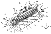
도 1은 싱글-패스 잉크젯 프린터(1)에 대한 3 차원 예시로 인쇄 구역(2)을 도시한다. 배향을 위해, 3 개의 공간 방향들(X, Y 및 Z)을 갖는 직교 좌표계(orthogonal coordinate system)가 예시된다.Figure 1 shows a
인쇄 매체(4)는 인쇄 작동 중 러닝 트랙(3)을 따라 Y 방향(진행 방향)으로 연속적으로 이동된다. 프린트 헤드 모듈(6)은 X 방향(횡 방향)으로 전체적인 인쇄 매체(4) 상에 연장하며, 이 프린트 헤드 모듈(6)은, 프린트 헤드 모듈(6)이 실질적으로 Z 방향(수직 방향)으로 직립으로 세워지도록 배향되는 인쇄 포지션의 싱글-패스 잉크젯 프린터(1)의 프레임 구조(8) 상의 유닛 상에 고정되게 장착된다.The
프린트 헤드 모듈(6)은 인쇄 매체(4) 상에 크로스멤버(loadbearing)(11)와 함께 횡방향으로 X 방향으로 연장하는 로드베어링(loadbearing) 프레임(10)을 포함한다. 횡 방향 브라켓(12)은 로드베어링 프레임(10)의 크로스멤버(11) 상에서 2 개의 사이드 칙들(side cheeks)(13)을 통해 현수되는(suspended) 방식으로 장착된다. 여기서, 장착은 X 방향으로 배향되는 선회 축(swing axis)을 중심으로 횡 방향 브라켓(12)의 선회(swinging)를 허용한다. 선회 축은, 특히 크로스멤버(11)를 통해 또는 크로스멤버(11) 바로 아래로 이어지며, 그 결과, 횡 방향 브라켓(12)의 중심이 Z 방향으로 크로스멤버(11) 아래에 위치된다. 프린트 헤드 모듈(6)이 Z 방향으로 수직으로 리프트 아웃된다면(lifted out), 횡 방향 브라켓(12)은 중력을 통해 크로스멤버(11) 아래로 배향되는 방식으로 정렬된다.The
다수의 프린트 헤드들(14)이 인쇄 매체(4) 상에 X 방향을 따라 횡 방향 브라켓(12) 상에 배열된다. 재료들을 작동시키기 위한, 또는 전기 에너지를 공급하기 위한 공급 라인들 및 제어 보드들(control boards)(15)이 로드베어링 프레임(10) 상에 장착된다. 그 결과, 프린트 헤드들(14)에 작용하는 프린트 헤드 모듈(6)의 컴포넌트들의 중량이 감소된다. 횡 방향 브라켓(12)의 중량에 의해 유도된 변형 및 그에 따라 조정되는 인쇄 포지션에 대한 프린트 헤드들(14)의 바람직하지 않은 변위가 방지된다. 이는 종래 기술과 비교하여 X 방향을 따라 프린트 헤드 모듈(6)의 치수가 증가되는 것을 허용한다. 도 1에서 도시되는 싱글-패스 잉크젯 프린터(1)의 횡 방향 브라켓(12)은, 예를 들어, X 방향으로 2.5 m 초과의 길이를 가진다.A plurality of
커플링 모듈(16)은 상세히 도시되지 않은 다중의 커플링을 통해 로드베어링 프레임(10)의 크로스멤버(11) 상에 커플링되고 분리될 수 있다. 여기서, 다중의 커플링은 커플링 모듈(16) 상에 배치되는 전기 모터(17)를 통해 작동된다. 예를 들어, 모터(17)는 스크류 연결들을 구동시키며(actuate), 이를 통해 커플링 모듈(16) 및 크로스멤버(11)가 공급 라인들, 제어 라인들 및/또는 전기 라인들의 동시적인 연결에 의해 서로 커플링된다. 커플링 동안, 크로스멤버(11) 및 커플링 모듈(16)은 서로 접근한다. 분리 동안, 크로스멤버(11) 및 커플링 모듈(16)은 서로 멀어지게 이동한다. 커플링 모듈(16)은 싱글-패스 잉크젯 프린터(1)의 공급 라인 및 제어 라인에 대한 프린트 헤드 모듈(6)의 간단한 연결을 가능하게 한다.The
프린트 헤드 모듈(6)을 Z 방향(수직 방향)으로 리프트 인 및 리프트 아웃하기 위해, 게다가, 예를 들어 케이블 체결 수단(cable fastening means)으로서 구성되는 장착 보조부들(19)이 커플링 모듈(16) 상에 배열된다. 리프팅/하강 디바이스(미도시)의 케이블 단부들이 장착 보조부들(19)에 커플링된다. 프린트 헤드 모듈(6)은, 케이블 길이가 리프팅/하강 디바이스에 의해 변경됨으로써 설치 또는 분해(dismantling)를 위해 상승되거나 하강된다. 게다가, 2 개의 잉크 저장소들(20)이 커플링 모듈(16) 상에 장착되며, 프린트 헤드들(14)에는 마찬가지로 다중의 커플링에 의해 커플링되는 공급 라인들을 통해 인쇄 작동 중에 잉크가 공급된다.In addition, mounting
프린트 헤드 모듈(6)의 크로스멤버(11)는 프레임 구조(8) 위까지 멀리 X 방향으로 측 방향으로(laterally) 연장하는 2 개의 지탱 아암들(carrying arms)(22)을 가진다. 로드베어링 프레임(10)이 프린트 헤드 모듈(6)의 상당한 중량을 지탱하는 양 측면들 상에 구성되는 로드베어링 구조(25)의 지탱 아암들(22) 및 그에 따라 로드베어링 프레임(10)이 여기서 보다 상세히 알 수 없는 지지 수단(24)을 통해 배치되며, 이의 부품을 위한 이 로드베어링 구조(25)는 싱글-패스 잉크젯 프린터(1)의 프레임 구조(8) 상에 장착된다. 명료성의 이유들로, 도 1의 단지 우측 로드베어링 구조(25)가 여기서 예시된다.The
지지 수단(24)을 통해 로드베어링 구조들(25) 상에 놓여지는(deposited) 프린트 헤드 모듈(6)은 중력을 통해 배향되는 방식으로 제공된 인쇄 포지션을 따라 이미 정렬된다. 이를 위해, 지탱 아암들(22)은 크로스멤버(11)에 관하여 수직 상방으로 안내된다. 이에 따라, 프린트 헤드 모듈(6)이 수직 방향으로 용이하게 싱글-패스 잉크젯 프린터(1)에 리프트 인 그리고 리프트 아웃될 수 있다. 지지 수단들(24)은 지탱 아암들(22) 상에, 각각의 경우에 로드베어링 구조(25)의 받침부(rest)(27) 상에 놓여진다. 받침부(27)는 상세도로 배척으로(enlarged scale) 도시된다. 각각의 받침부(27)는 볼 조인트로 회전가능하게 이동가능한 방식으로 장착되는 평면식 지지 면(28)을 포함한다. 받침부(27)의 지지 면(28)은 놓여진 로드베어링 프레임(10)의 중량을 통해 볼 조인트에서 배향되며, 그 결과 지지 수단(24)과 받침부(27) 사이에 평탄한 접촉이, 심지어 프린트 헤드 모듈(6)의 경사진 각도(이 경사진 각도는 인쇄 포지션에서 가능하게는 요망됨)의 경우에조차, 항상 존재한다.The
베어링 피스들(30)은, 각각의 경우에 선회 방식으로 현수되는(suspended) 횡 방향 브라켓(12)의 사이드 칙들(13)의 하부 단부들에 장착된다. 중력을 통해 이미 사전-배향되어 있는 프린트 헤드 모듈(6)이 리프트 인될(lifted in) 때, 베어링 피스들(30)은 개방 베어링들(34)의 상응하는 베어링 시트들에 대해 각각의 캐칭 수단(32)에 의해 정밀하게 조정된다. 여기서, 캐칭 수단들(32)은, 각각의 경우에 캐칭 웨지(wedge) 및 상기 캐칭 웨지를 수용하는 웨지 샤프트(wedge shaft)의 조합으로 구성된다. 베어링 피스들(30)은, 예를 들어, 볼 피봇들(ball pivots)로서 구성된다. 이를 위해, 프레임 구조 상의 러닝 트랙(3)의 양 측면들 상에 배열되는 개방 베어링들(34)의 베어링 시트들은, 바람직하게는 원뿔형, 구형 또는 각기둥형(prismatic) 시트들로서 구성된다. 여기서, 개방 베어링들(34) 중 하나의 개방 베어링은 추가적으로 바람직하게는 X 방향에 대해 고정된 베어링으로서 구성되며, 그리고 개방 베어링들(34) 중 다른 하나의 개방 베어링은 플로팅(floating) 베어링으로서 구성된다. 그 결과, 예를 들어 일 측면 상의 구형 또는 원뿔형 시트와의, 그리고 프린트 헤드 모듈(6)의 다른 측면 상의 각기둥형 시트와의 베어링 조합이 형성된다. X 방향으로 연장하는 각기둥형 시트는 X 방향으로의 변위가능성을 허용하지만, Y 좌표 및 Z 좌표는 고정된다. 열 순환으로 인한 X 방향으로의 프린트 헤드 모듈(6)의 길이 방향 오프셋은 개방 베어링들(34)에서 이러한 유형의 고정된/플로팅 베어링 조합을 통해 규정된 방식으로 흡수된다. 특히, X 방향으로의 프린트 헤드 모듈의 크리핑 오프셋(creeping offset)이 방지되는데, 왜냐하면 길이 방향 팽창 및 길이 방향 수축 양자 모두가 베어링들(34) 중 항상 동일한 베어링을 통해, 즉 플로팅 베어링을 통해 규정된 방식으로 흡수되기 때문이다.The bearing
싱글-패스 잉크젯 프린터(1) 내에 수용되는 프린트 헤드 모듈(6)의 인쇄 포지션(이 인쇄 포지션에서, 프린트 헤드 모듈이 유닛 상에 고정됨)을 고정하기 위해, 정지 피스(36)가 횡 방향 브라켓(12)의 사이드 칙(13) 상에 장착된다. 정지 피스(36)는 프레임 구조(8)의 정지 면(38)에 대해 규정된다. 프린트 헤드 모듈(6)이 리프트 인될 때, 프린트 헤드 모듈(6)의 경사 또는 극 각도(polar angle)가 정지 피스(36) 및 정지 면(38)을 통해 인쇄 포지션(이 프린팅 포지션에서 프린트 헤드 모듈이 유닛 상에 고정됨)에서 규정된다.The
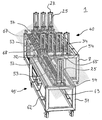
도 2는 도 1에 따른 싱글-패스 잉크젯 프린터(1)의 전체 구성을 위에서부터 본 평면도를 개략적으로 도시한다. 도 1에 도시되는 인쇄 구역(2)은 평면도에서 보일 수 있으며, 3 개의 프린트 헤드 모듈들(6)은 각각의 경우에 이들의 상응하는 인쇄 포지션(47)에서 예로써 인쇄 매체(4)의 Y 방향(진행 방향)으로 연달아(behind one another) 리프트 인된다(lifted in). 여기서, 인쇄 구역(2) 내로 리프팅되는 프린트 헤드 모듈들(6)의 각각은 인쇄 매체(4)를 특정 색 또는 잉크로 인쇄하기 위해 제공된다.Fig. 2 schematically shows a plan view of the entire configuration of the single-
인쇄 구역(2)으로부터 Y 방향으로 이격되는 방식으로, 게다가, 싱글-패스 잉크젯 프린터(1)는, 저장 구역(40)을 포함하고, 프린트 헤드 모듈들(6)은 수직 방향으로 리프트 아웃된 후에 Y 방향으로의 이동 및 후속하는 하강을 통해 리프팅/하강 디바이스(여기서 미도시됨)에 의해 인쇄 구역(2)으로부터 프린트 헤드들을 보호하기 위해 또는 세정 목적들을 위해 이 저장 구역에 도입된다. 본 경우에, 3 개의 프린트 헤드 모듈들(6)은 이들 각각의 저장 포지션(49)에서 저장 구역(40)으로 리프트 인된다.In addition, the single-
게다가, 외부 유지보수를 위해 또는 개별 프린트 헤드 모듈들(6)을 교환하기 위해, 싱글-패스 잉크젯 프린터(1)는 X 방향으로 저장 구역(40)의 측 방향으로 배열되는 유지보수 구역(45)을 포함한다. 유지보수 구역(45)은, 예를 들어, 가동 유지보수 캐리지(mobile maintenance carriage)(51)로서 구성되며, 가동 유지보수 캐리지는 특히 Y 방향으로 이동될 수 있고, 저장 구역(40)에 커플링될 수 있도록 구성된다. 개별 프린트 헤드 모듈들(6)은 저장 구역(40)과 유지보수 구역(45) 사이에서 측 방향으로 푸시 인되거나 푸시 아웃됨으로써 변경된다. 유지보수 구역(45)의 각각의 유지보수 포지션(50)에 위치된 프린트 헤드 모듈들(6)은 검사 또는 교환의 목적을 위해 유지보수 캐리지(51)의 이동을 통해 다른 위치로 이동된다.In addition, for external maintenance or to replace
도 3은 하나의 예시적인 개량예에서 싱글-패스 잉크젯 프린터(1)의 저장 구역(40) 및 유지보수 구역(45)의 3 차원 도면을 도시한다. 유지보수 구역(45)은 이동가능한 유지보수 캐리지(51)로서 구성된다. 도시된 상황에서, 프린트 헤드 모듈(6)은 저장 구역(40)이나 유지보수 구역(45) 내로 리프팅되지 않는다.Figure 3 shows a three-dimensional view of the
프레임 구조(52)는 저장 구역(40) 상에서 보일 수 있다. 수용된 프린트 헤드 모듈들(6)의 프린트 헤드들을 커버하기 위한 보호 커버(53)가 저장 구역(40)의 각각의 저장 포지션(49)에 구성된다. 보호 커버(53)는 각각의 경우에 X 방향으로 변위될 수 있는 저장 장치(54)의 고정된 구성 부품이며, 그리고 각각의 경우에 그 부품을 위해 인쇄 구역(2)(도 1 참조)을 따라 구성된, 받침부들(27) 및 캐칭 수단(32)을 포함하는 로드베어링 구조들(25)을 가진다. 그곳에서 인쇄 구역(2) 밖으로 또는 이들의 인쇄 포지션(47) 밖으로 수직 방향으로 리프팅되는 프린트 헤드 모듈들(6)은 상응하는 배향으로 각각의 저장 장치(54) 내로 이에 상응하게 리프팅될 수 있다. 여기서, 프린트 헤드 모듈들(6)의 지지 수단(24)은, 이에 따라, 각각의 저장 장치들(54)의 상응하는 받침대들(27) 상에 놓인다. 리프트 인된 프린트 헤드 모듈들(6)의 베어링 피스들(30)은 상응하는 개방 베어링들(34)에 포지셔닝된다. 이들의 상응하는 정지 피스들(36)을 통해 리프트 인된 프린트 헤드 모듈들(6)을 경사지게 하기 위한 정지 면들(38)만이 저장 장치들(54)에 제공되지는 않는다. 프린트 헤드 모듈들(6)은 각각의 저장 포지션(49)에서 수직 방향으로 배향되는 방식으로 직립으로 세워진 채(stand upright) 리프트 인된다.The frame structure 52 may be visible on the
도시된 예시적인 실시예에서 4 개의 저장 장치들(54) 각각은 안내 엘리먼트들(57)에 의해 프레임 구조(52) 상으로 안내되어, 저장 장치들 각각이 X 방향으로 변위될 수 있다. 유지보수 캐리지(51)가 저장 구역(40)에 대해 Y 방향으로 상응하게 포지셔닝된다면, 저장 구역(40)의 안내 엘리먼트들(57)은, X 방향을 따라 연속적인 변위 트랙(60)을 형성하도록 유지보수 캐리지(51)의 상응하는 안내 엘리먼트들(57)과 커플링될 수 있다. 안내 엘리먼트들(57) 이외에도, 유지보수 캐리지(51)는 수용된 프린트 헤드 모듈(6)의 커버 플레이트들을 저장하는 역할을 하는 리테이닝 브라켓들(retaining brackets)(62)을 갖는다. 이러한 유형의 커버 플레이트들(미도시)은, 내부 공간을 커버하기 위해 그리고 기계적 안정화를 위해 프린트 헤드 모듈들에서 개방된 측면들 상에 도 1에 따른 프린트 헤드 모듈들(6) 상에 장착된다. 커버 플레이트는 또한, 특히, 도 5 및 도 6으로부터 모여있을 수 있다(부호 66 참조).In the illustrated exemplary embodiment each of the four
함께 형성된 연속적인 변위 트랙(60)을 통해, 리프트 인되는 프린트 헤드 모듈(6)을 갖는 저장 장치(54)는 유지보수 구역(45) 내로 저장 구역(40) 밖으로 그리고 그 반대로 변위될 수 있다. 리프트 인되는 각각의 프린트 헤드 모듈(6)은 별도로 푸시 인되거나 푸시 아웃될 수 있다. 저장 장치(54)의 변위 이동을 제한하기 위해, 정지 버퍼(63)가 유지보수 캐리지(51)의 단부 측면 상에 장착된다.The
게다가, 세정 디바이스(64)는 도시된 싱글-패스 잉크젯 프린터(1)의 저장 구역(40)에 구성된다. 여기서, 세정 디바이스(64)는 설정된 프린트 헤드 모듈들(6)의 프린트 헤드들에 대해 아래로부터 지향되는 복수의 개별 닥터 블레이드들(65)을 포함한다. 닥터 블레이드들(65)은 마찬가지로 변위가능한 저장 장치(54)의 부분이고, 닥터 블레이드 드라이브 디바이스(도 8의 부호 87)를 통해 왕복 이동(to and fro movement)으로 X 방향으로 변위될 수 있다.In addition, the
도 4는 3 차원 도면으로 도 3에 따른 싱글-패스 잉크젯 프린터(1)의 저장 구역(40) 및 유지보수 구역(45)을 도시한다. 그러나, 도 3과 비교하여, 도 4에서 저장 장치들(54) 중 하나의 저장 장치는, 그 후, 저장 구역(40)의 그리고 유지보수 구역(45)의 안내 엘리먼트들(67)에 의해 형성되는 변위 트랙(60)을 따라 유지보수 캐리지(51) 상으로 X 방향으로 푸시 아웃된다. 여기서, 푸시 아웃되는 저장 장치(54)는 유지보수 캐리지(51)의 정지 버퍼(63)와 접촉하게 된다. 특히, 로드베어링 구조들(25), 캐칭 수단(32), 개방 베어링들(34) 및 닥터 블레이드(65)를 포함하는 저장 장치(54)가 유지보수 캐리지(51) 상으로 변위되는 것을 알 수 있다. 닥터 블레이드들(65)은, 특히, 보호 커버(53)의 내부에 장착된다.FIG. 4 shows a
도 5 및 도 6은, 다른 관점으로부터, 즉 Y 방향(진행 방향)의 시야 방향으로부터 도 3 및 도 4에 따른 싱글-패스 잉크젯 프린터(1)의 저장 구역(40) 및 유지보수 구역(45)을 도시한다. 그러나, 도 3 및 도 4와 대조하여, 도 1에 따른 프린트 헤드 모듈(6)은, 그 후, 각각의 저장 장치(54) 내로 리프팅된다. 특히, 프린트 헤드 모듈(6)의, 측 방향 지탱 아암들(22), 커플링 모듈(16), 모터(17) 및 정지 피스(36)를 볼 수 있다. 프린트 헤드 모듈(6)의 받침부들(27)은 양 측면들 상에 배열되는 로드베어링 구조들(25)의 지지 면(28) 상에 놓인다. 베어링 피스들(30)은 저장 장치(54)의 상응하는 개방 베어링(34)에 수용된다. 도 5 및 도 6에서, 프린트 헤드 모듈(6)은 삽입된 커버링 플레이트들(66)로 도시된다.5 and 6 show the
도 5에서, 프린트 헤드 모듈(6)은 저장 장치(54)에 의해 저장 구역(40)에 포지셔닝된다. 도 6에서, 저장 장치(54)는 수용된 프린트 헤드 모듈(6)에 의해 유지보수 캐리지(51) 상으로 푸시 아웃된다. 정지 버퍼(63)에 대한 접촉을 볼 수 있다.In FIG. 5, the
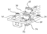
도 7은 세정 디바이스(64)의 상세를 부분적으로 단면도로 그리고 부분적으로 평면도로 도시한다. 상기 상세에서, 특히, 설정된 프린트 헤드 모듈들(6)의 프린트 헤드들을 세정하기 위한 닥터 블레이드들(65)의 장착을 볼 수 있다.Figure 7 shows the details of the
세정 디바이스(64)의 각각의 닥터 블레이드(65)에는 닥터 블레이드 설정 디바이스(67)가 할당된다. 각각의 닥터 블레이드 설정 디바이스(67)는, 예를 들어 자기(magnetic) 엘리먼트(81)로서 구성되는 설정 엘리먼트(68)를 포함한다. 닥터 블레이드들(65)은 왕복 이동으로 X 방향으로 변위될 수 있는 닥터 블레이드 캐리어(70) 상에 함께 장착된다. 이를 위해, 상응하는 안내 롤러들(71)을 볼 수 있다. 닥터 블레이드 캐리어(70)에 대해, 닥터 블레이드들(65)은, 닥터 블레이드들이 Z 방향으로 변위될 수 있도록 각각의 경우에 지탱 엘리먼트(73)에 의해 차례로 장착된다. 이를 위해, 각각의 닥터 블레이드(65)의 지탱 엘리먼트(73)는, 각각의 경우에 X 방향으로 연장하는 제 1 안내 트랙(77)에서 또는 X 방향으로 연장하는 제 2 안내 트랙(78)에서 각각의 경우에 각각의 맞물림 엘리먼트(74)에 의해 안내된다. 양자 모두의 안내 트랙들(77, 78)은 실질적으로 Z 방향으로 연장하는 연결 섹션(80)을 통해 서로 커플링된다. 닥터 블레이드 캐리어(70)는 세정 작동 중에 세정 디바이스(64)의 컴포넌트들에 대해 X 방향으로 이동한다.Each of the
본 경우에, 도시되는 닥터 블레이드(65)는 거리 포지션(distance position)(A)에 위치되며, 맞물림 엘리먼트(74)는 제 2 안내 트랙(78)에서 안내된다. 닥터 블레이드 캐리어(70)가 X 방향으로 이동된다면, 닥터 블레이드(65)는 설정된 프린트 헤드 모듈(6)의 프린트 헤드(14)에 대해 Z 방향에 관한 거리 포지션으로 유지된다. 닥터 블레이드(65)는 세정 포지션에서보다 각각 할당된 프린트 헤드(14)로부터 더 이격된다.In this case, the
지탱 엘리먼트(73)는 닥터 블레이드 캐리어(70)에 대해 Z 방향으로 사전-응력을 받는다(prestressed). 상기 설정 엘리먼트(68)가 활성화되지 않고 지탱 엘리먼트(73)가 세정 이동 중에 설정 엘리먼트(68)와 정렬된다면, 맞물림 엘리먼트(74)는 기계적 사전응력(prestress)으로 인해 연결 섹션(80)을 따라 상방으로 당겨진다. 닥터 블레이드 캐리어(70)의 복귀 이동 중에, 닥터 블레이드(65)는, 그 후, 세정 포지션(R)에 위치되며, 맞물림 엘리먼트(74)는 제 1 안내 트랙(77)에서 안내된다. 다시 말해, 세정 포지션(R)은 닥터 블레이드(65)의 기계식으로 미리규정된 포지션이다. 닥터 블레이드(65)가 거리 포지션(A) 내로 이동될 수 있다면, 설정 엘리먼트(68) 또는, 예로써, 자기 엘리먼트(81)는, 지탱 엘리먼트(73)가 정렬된다면 세정 이동 중에 활성화된다. 이러한 방식으로, 맞물림 엘리먼트(74)는 연결 섹션(80)을 통해 기계적 사전응력에 반대로 제 2 안내 트랙(78) 내로 이동되거나, 제 2 안내 트랙에 유지되며, 그 결과 거리 포지션(A)이 닥터 블레이드 캐리어(70)의 세정 이동(X 방향의 왕복 이동) 중에 주어진다. 활성화된 자기 엘리먼트(81)는 기계적 사전응력에 반대로 지탱 엘리먼트(73) 상에서 상응하게 강자성(ferrimagnetic)이거나 또는 강자성 재료 엘리먼트 상에 작용한다.The
도시되는 세정 디바이스(64)는 세정 포지션(R)(닥터 블레이드(65)가 설정된 프린트 헤드 모듈(6)의 프린트 헤드(14)에 가까운, 바람직하게는 프린트 헤드(14)에 접함)과 거리 포지션(A)(닥터 블레이드(65)가 프린트 헤드(14)로부터 더 이격됨) 사이에서 각각의 닥터 블레이드(65)를 별도로 전환하는 것을 가능하게 한다. 설정된 프린트 헤드 모듈(6)의 각각의 프린트 헤드(14)에는 닥터 블레이드(65)가 할당된다면, 세정을 위해 별도로 각각의 프린트 헤드(14)를 구동시키는 것이 가능하게 된다.The illustrated
도 8에서, 저장 구역(40)의 상세들 그리고 특히 변위가능한 저장 장치들(54)의 상세들이 평면도로 보일 수 있다. 푸시 인되는(pushed in) 저장 장치(54)의 보호 커버(53)를 명확하게 볼 수 있다. 전방 저장 장치(54)(도 8에서 저부에 있음)는 푸시 아웃된다.In FIG. 8, the details of the
각각의 저장 장치(54)는, X 방향으로 변위될 수 있는 닥터 블레이드 캐리어(70)를 포함하고 도 7에 따라 그 위에 장착되는 복수의 닥터 블레이드들(65)을 지탱한다. 각각의 경우에, 하나의 닥터 블레이드 드라이브 디바이스(87)가 X 방향을 따라 왕복 이동으로 닥터 블레이드 캐리어(70)를 변위시키기 위해 할당된다. 이를 위해, 예를 들어, 스핀들 드라이브(spindle drive)를 통해 닥터 블레이드 캐리어(70) 상에 직접 작용하는 전기 모터가 제공된다. 게다가, 도 8에서, 좌측 개방 베어링(34)은 푸시 인된 저장 장치(54) 상에서 명확하게 볼 수 있으며, 이 개방 베어링(34)은 설정된 프린트 헤드 모듈(6)의 베어링 피스(30)를 수용하기 위한 원뿔형 시트를 포함하며, 이 베어링 피스(30)는 볼 피봇으로서 구성된다. 게다가, 캐칭 수단(32)(본 경우에는, 캐칭 웨지) 및 로드베어링 구조(25)의 일부분을 볼 수 있다.Each
저장 장치(54)가 X 방향으로 안내 엘리먼트들(57)(상응하는 안내 롤러(85)가 도 7 및 도 8에서 도시됨)을 따라 변위된다면, 세정 디바이스(64)의 상응하는 설정 엘리먼트들(68) 또는 자기 엘리먼트들(81)은 저장 구역(40)에 유지된다. 설정된 프린트 헤드 모듈(6)은 저장 장치(54) 상에 포지셔닝되는 것을 견고하게 그리고 안정적으로 유지되며, 프린트 헤드들(14)은 보호 커버(53)에서 견고하게 보호되는 방식으로 계속 유지된다. 닥터 블레이드 설정 디바이스(67)가 분리된다. 저장 장치(54)가 안으로 이동된다면, 저장 장치는 보호 커버(53)의 저부를 통해 작용한다.If the
도 9는 닥터 블레이드 캐리어(70)의 상세도를 도시한다. 지탱 엘리먼트(73) 및 지탱 엘리먼트 상에 장착되는 맞물림 엘리먼트(74)는, 그 후, 명백하게 보일 수 있으며, 이 맞물림 엘리먼트(74)는 도 7에 따른 안내 트랙들(77, 78)에서 포지티브식으로(positively) 안내된다. 지탱 엘리먼트(73)는 스프링 엘리먼트(88)를 통해 닥터 블레이드 캐리어(70)에 관해 상방으로 사전-응력을 받는다. 안내 롤러들(71)은 마찬가지로 명백하게 보일 수 있으며, 안내 롤러(71)의 회전 축들은 Z 방향으로 그리고 Y 방향으로 연장한다.9 shows a detail view of the
1
싱글-패스 잉크젯 프린터
2
인쇄 구역
3
러닝 트랙
4
인쇄 매체
6
프린트 헤드 모듈
8
프레임 구조
10
로드베어링 프레임
11
크로스멤버
12
횡 방향 브라켓
13
사이드 칙
14
프린트 헤드들
15
제어 보드
16
커플링 모듈
17
모터
19
장착 보조부
20
잉크 저장소
22
지탱 아암
24
지지 수단
25
로드베어링 구조
27
받침대
28
지지 면
30
베어링 피스
32
캐칭 수단
34
개방 베어링
36
정지 피스
38
정지 면
40
저장 구역
45
유지보수 구역
47
인쇄 포지션
49
저장 포지션
50
유지보수 포지션
51
유지보수 캐리지
52
프레임 구조
53
보호 커버
54
저장 장치
57
안내 엘리먼트
60
변위 경로
62
리테이닝 브라켓
63
정지 버퍼
64
세정 디바이스
65
닥터 블레이드
66
커버링 플레이트
67
닥터 블레이드 설정 디바이스
68
설정 엘리먼트
70
닥터 블레이드 캐리어
71
안내 롤러
73
지탱 엘리먼트
74
맞물림 엘리먼트
77
제 1 안내 트랙
78
제 2 안내 트랙
80
연결 섹션
81
자기 엘리먼트
85
안내 롤러
87
닥터 블레이드 드라이브 디바이스
88
스프링 엘리먼트
R
세정 포지션
A
거리 포지션1 single-pass inkjet printer
2 printing area
3 Running Tracks
4 Print media
6 Printhead Module
8 frame structure
10 Rod bearing frames
11 Cross members
12 Lateral Bracket
13 Side Chicks
14 Printheads
15 control board
16 coupling module
17 Motor
19 Mounting Support
20 Ink storage
22 support arm
24 support means
25 Load bearing construction
27 Pedestal
28 Support surface
30 Bearing piece
32 catching means
34 Open bearing
36 Stopper piece
38 stop face
40 Storage Area
45 Maintenance Area
47 Printing Position
49 Storage Position
50 Maintenance Position
51 Maintenance carriage
52 frame structure
53 Protection cover
54 Storage Devices
57 guide element
60 displacement path
62 Retaining bracket
63 stop buffer
64 cleaning device
65 Doctor Blades
66 Covering Plate
67 Doctor blade setting device
68 Configuration element
70 Doctor blade carrier
71 guide roller
73 support element
74 Engaging element
77 1st guide track
78 2nd Guide Track
80 Connection Section
81 magnetic element
85 guide rollers
87 Doctor blade drive device
88 spring element
R Cleaning Position
A Street Position
Claims (13)
인쇄 매체(printing medium)를 Y 방향으로 안내하기 위한 러닝 트랙(running track)(3)을 가지고, Y 방향으로 연달아(behind one another) 배열되고 각각의 경우에 상기 러닝 트랙(3)에 걸쳐 횡 방향으로 X 방향으로 복수의 프린트 헤드들(print heads)(14)과 연장하는 복수의 프린트 헤드 모듈들(modules)(6)을 가지고, 그리고 인쇄 구역(printing region)(2)을 가지며, 상기 인쇄 구역에서 상기 프린트 헤드 모듈들(6)은 상기 프린트 헤드 모듈들이 실질적으로 Z 방향으로 각각의 인쇄 포지션(printing position)(47)에서 직립으로 세워지도록 장착될 수 있고, Z 방향을 따라 가역적으로 삽입 및 제거될 수 있으며,
상기 인쇄 구역(2) 이외에도, 저장 구역(40)이 포함되며, 상기 저장 구역에서, 다수의 프린트 헤드 모듈들(6)은, 상기 프린트 헤드 모듈들이 각각의 저장 포지션(49)에서 실질적으로 Z 방향으로 직립으로 세워지도록 장착될 수 있고, 그리고 Z 방향을 따라 가역적으로 삽입 및 제거될 수 있으며, 상기 저장 포지션(49)에 설정되는 상기 프린트 헤드 모듈들(6)의 프린트 헤드들(14)은 보호 커버(53)에서 수용되는,
싱글-패스 잉크젯 프린터(1).
A single-pass inkjet printer (1) comprising:
A running track (3) for guiding a printing medium in the Y direction, arranged in the Y direction one behind the other and in each case in the transverse direction across the running track (3) Having a plurality of printheads (14) and a plurality of printhead modules (6) extending in the X direction with a printing region (2) in the X direction, The printhead modules 6 can be mounted such that the printhead modules are erected substantially upright at respective printing positions 47 in the Z direction and can be reversibly inserted and removed along the Z direction Lt; / RTI >
In addition to the printing zone 2, a storage zone 40 is also included, in which the plurality of printhead modules 6 are arranged such that the printhead modules are positioned substantially in the Z- And the print heads 14 of the print head modules 6, which are set in the storage position 49, can be reversibly inserted and removed along the Z direction, The cover 53,
Single-pass inkjet printer (1).
세정 디바이스(64)가 상기 저장 구역(40)에 배열되며, 상기 세정 디바이스(64)는 다수의 닥터 블레이드 캐리어들(doctor blade carriers)(70)을 포함하며, 상기 다수의 닥터 블레이드 캐리어들은 각각의 경우에 하나의 저장 포지션(49)에 할당되고, 특히 X 방향으로 변위될 수 있으며, 그리고 각각의 경우에 다수의 닥터 블레이드들(doctor blades)(65)을 지탱하는,
싱글-패스 잉크젯 프린터(1).
The method according to claim 1,
A cleaning device 64 is arranged in the storage compartment 40 and the cleaning device 64 includes a plurality of doctor blade carriers 70, In particular in the X-direction, and in each case supporting a plurality of doctor blades 65,
Single-pass inkjet printer (1).
정확하게 하나의 상기 닥터 블레이드(65)가 설정된 프린트 헤드 모듈(6)의 각각의 프린트 헤드(14)를 위해 상기 또는 각각의 닥터 블레이드 캐리어(70) 상에 할당되는,
싱글-패스 잉크젯 프린터(1).
3. The method of claim 2,
Precisely one doctor blade 65 is assigned on the or each doctor blade carrier 70 for each printhead 14 of the set printhead module 6,
Single-pass inkjet printer (1).
상기 세정 디바이스(64)는 하나의 또는 각각의 닥터 블레이드 캐리어(70)를 특히 X 방향을 따라 변위시키기 위한 드라이브 디바이스(87)를 포함하는,
싱글-패스 잉크젯 프린터(1).
The method according to claim 2 or 3,
The cleaning device 64 includes a drive device 87 for displacing one or each doctor blade carrier 70, particularly along the X direction.
Single-pass inkjet printer (1).
각각의 저장 포지션(49)에서, 상기 세정 디바이스(64)는 각각의 경우에 하나의 닥터 블레이드 캐리어(70)를 변위시키기 위한 드라이브 디바이스를 포함하는,
싱글-패스 잉크젯 프린터(1).
5. The method of claim 4,
In each storage position 49, the cleaning device 64 includes a drive device for displacing one doctor blade carrier 70 in each case.
Single-pass inkjet printer (1).
상기 또는 각각의 닥터 블레이드(65)는 상기 닥터 블레이드가 세정 포지션(cleaning position)(R)과 거리 포지션(distance position)(A) 사이에서 Z 방향으로 조정될 수 있도록 별개의 상기 닥터 블레이드 캐리어(70) 상에서 안내되며, 그리고 닥터 블레이드 설정 디바이스(67)가 각각의 경우에 하나의 닥터 블레이드(65)를 상기 세정 포지션(R)과 상기 거리 포지션(A) 사이에서 조정하기 위해 포함되는,
싱글-패스 잉크젯 프린터(1).
6. The method according to any one of claims 2 to 5,
The or each doctor blade 65 is positioned on a separate doctor blade carrier 70 so that the doctor blade can be adjusted in the Z direction between the cleaning position R and the distance position A. [ And the doctor blade setting device 67 is included in each case to adjust one doctor blade 65 between the cleaning position R and the distance position A,
Single-pass inkjet printer (1).
상기 또는 각각의 닥터 블레이드(65)는 특히 X 방향으로 연장하는 제 1 안내 트랙(77)을 따라 상기 세정 포지션(R)에서 포지티브식으로(positively) 안내되고, 특히 X 방향으로 연장하는 제 2 안내 트랙(78)을 따라 상기 거리 포지션(A)에서 포지티브식으로 안내되며, 상기 제 1 안내 트랙(77) 및 상기 제 2 안내 트랙(78)은 연결 섹션(connecting section)(80)을 통해 서로 연결되며, 그리고 상기 각각의 닥터 블레이드 설정 디바이스(67)는 취해진(taken) 상기 안내 트랙(77, 78)의 전환가능한 결정을 위해 구성되는,
싱글-패스 잉크젯 프린터(1).
The method according to claim 6,
The or each doctor blade 65 is guided positively in the cleaning position R along a first guiding track 77 which extends in the X direction in particular and is guided positively in the cleaning position R, The first guide track 77 and the second guide track 78 are guided along the track 78 positively at the distance position A and the first guide track 77 and the second guide track 78 are connected to each other via a connecting section 80. [ And wherein each of the doctor blade setting devices (67) is configured for switchable determination of the guide tracks (77, 78) taken,
Single-pass inkjet printer (1).
상기 또는 각각의 닥터 블레이드(65)는 상기 제 1 안내 트랙(77) 및 상기 제 2 안내 트랙(78)에서 맞물림 엘리먼트(74)에 의해 안내되며, 그리고 상기 닥터 블레이드 설정 디바이스(67)는 상기 연결 섹션(80)에서 상기 별개의 맞물림 엘리먼트(74) 상에 작용하는 자기(magnetic) 엘리먼트(81)를 포함하는,
싱글-패스 잉크젯 프린터(1).
8. The method of claim 7,
The or each doctor blade 65 is guided by the engagement element 74 at the first guide track 77 and the second guide track 78 and the doctor blade setting device 67 is connected to the connection And a magnetic element (81) acting on the separate engaging element (74) in the section (80).
Single-pass inkjet printer (1).
유지보수 구역(45)이 상기 저장 구역(40)에 대해 X 방향으로 오프셋되는(offset) 방식으로 또한 포함되며, 상기 유지보수 구역(45)에서, 상기 프린트 헤드 모듈들(6)은, 상기 프린트 헤드 모듈들이 각각의 유지보수 포지션(50)에서 실질적으로 Z 방향으로 직립으로 세워지도록 장착될 수 있고, Z 방향을 따라 가역적으로 삽입 및 제거될 수 있는,
싱글-패스 잉크젯 프린터(1).
9. The method according to any one of claims 1 to 8,
A maintenance zone 45 is also included in a manner offset in the X direction with respect to the storage zone 40 wherein in the maintenance zone 45 the printhead modules 6 are mounted in the print The head modules can be mounted so as to stand upright substantially in the Z direction at each maintenance position 50 and can be reversibly inserted and removed along the Z direction,
Single-pass inkjet printer (1).
상기 저장 구역(40)은, 상기 또는 각각의 프린트 헤드 모듈(6)을 위해, 각각의 경우에 상기 X 방향으로 변위될 수 있는 하나의 저장 장치(54)를 제공하며, 그리고 상기 저장 장치에서 설정된 프린트 헤드 모듈(6)이 이의 저장 포지션(49)을 취하며(assume), 상기 보호 커버(53)는 상기 저장 장치(54)의 일부이며, 그리고 상기 저장 구역(40) 및 상기 유지보수 구역(45)은, 상기 또는 각각의 저장 장치(54)가 상기 저장 구역(40)에서 벗어나 상기 유지보수 구역(45)으로 Z 방향으로 설정된 프린트 헤드 모듈(6)과 함께 변위될 수 있는 방식으로 커플링될 수 있는,
싱글-패스 잉크젯 프린터(1).
10. The method of claim 9,
The storage zone 40 provides one storage device 54, which can be displaced in the X direction in each case, for the or each printhead module 6, Assume that the printhead module 6 assumes its storage position 49 and that the protective cover 53 is part of the storage device 54 and that the storage area 40 and the maintenance area 45 are arranged in such a manner that the or each storage device 54 can be displaced from the storage zone 40 and displaced with the printhead module 6 set in the Z direction into the maintenance zone 45. [ To be able,
Single-pass inkjet printer (1).
상기 저장 구역(40) 및 상기 유지보수 구역(45)은 각각의 경우에 상기 또는 각각의 저장 장치(54)를 안내하기 위한 안내 엘리먼트들(57)을 가지며, 상기 저장 구역(40)의 안내 엘리먼트들(57) 및 상기 유지보수 구역(45)의 안내 엘리먼트들(57)이 X 방향으로 연속되는 변위 트랙(60)을 형성하기 위해 서로 커플링되는 것이 가능한,
싱글-패스 잉크젯 프린터(1).
11. The method of claim 10,
The storage zone (40) and the maintenance zone (45) each have guide elements (57) for guiding the or each storage device (54) in each case, And the guide elements 57 of the maintenance area 45 can be coupled to each other to form a continuous displacement track 60 in the X direction,
Single-pass inkjet printer (1).
상기 유지보수 구역(45)은 가동 유지보수 캐리지(mobile maintenance carriage)(51)로서 구성되는,
싱글-패스 잉크젯 프린터(1).
The method according to claim 10 or 11,
The maintenance zone 45 is configured as a mobile maintenance carriage 51,
Single-pass inkjet printer (1).
상기 유지보수 구역(45)은 안으로 이동되는 하나의 또는 각각의 저장 장치(54)를 위한 고정 엘리먼트(fixing element) 및 정지 버퍼(stop buffer)(63)를 포함하는,
싱글-패스 잉크젯 프린터(1).13. The method according to any one of claims 10 to 12,
The maintenance zone 45 comprises a fixing element and a stop buffer 63 for one or each storage device 54 being moved in.
Single-pass inkjet printer (1).
Applications Claiming Priority (3)
| Application Number | Priority Date | Filing Date | Title |
|---|---|---|---|
| DE102015201776 | 2015-02-02 | ||
| DE102015201776.1 | 2015-02-02 | ||
| PCT/EP2015/054201 WO2016124256A1 (en) | 2015-02-02 | 2015-02-27 | Single-pass inkjet printer |
Publications (1)
| Publication Number | Publication Date |
|---|---|
| KR20170110683A true KR20170110683A (en) | 2017-10-11 |
Family
ID=52737068
Family Applications (1)
| Application Number | Title | Priority Date | Filing Date |
|---|---|---|---|
| KR1020177024742A KR20170110683A (en) | 2015-02-02 | 2015-02-27 | Single-pass inkjet printer |
Country Status (12)
| Country | Link |
|---|---|
| US (1) | US10252531B2 (en) |
| EP (1) | EP3253581B1 (en) |
| JP (1) | JP6633088B2 (en) |
| KR (1) | KR20170110683A (en) |
| CN (1) | CN107206794B (en) |
| CA (1) | CA2975421C (en) |
| ES (1) | ES2915098T3 (en) |
| IL (1) | IL253392B (en) |
| PL (1) | PL3253581T3 (en) |
| PT (1) | PT3253581T (en) |
| RU (1) | RU2685844C2 (en) |
| WO (1) | WO2016124256A1 (en) |
Families Citing this family (8)
| Publication number | Priority date | Publication date | Assignee | Title |
|---|---|---|---|---|
| DE202017106430U1 (en) * | 2017-10-24 | 2018-10-25 | Francotyp-Postalia Gmbh | Gutverarbeitungsgerät |
| FR3082780B1 (en) * | 2018-06-21 | 2020-07-24 | Reydel Automotive Bv | PRINTING OR COATING INSTALLATION OF SURFACES OF THREE-DIMENSIONAL PARTS |
| EP3847024A4 (en) | 2018-09-04 | 2022-11-09 | Prototype and Production Systems, Inc. | Printhead assembly guidance and positioning system |
| KR20210072777A (en) * | 2018-10-05 | 2021-06-17 | 멤젯 테크놀로지 엘티디 | Integrated inkjet module for scalable printers |
| US11731428B2 (en) | 2018-10-22 | 2023-08-22 | Bobst Mex Sa | Capping unit, maintenance device and printer |
| US11203212B2 (en) * | 2019-12-13 | 2021-12-21 | Electronics For Imaging, Inc. | Wide format staggered single pass printing apparatus |
| JP2022125524A (en) | 2021-02-17 | 2022-08-29 | 株式会社Screenホールディングス | Printer, and head maintenance method in printer |
| WO2023148634A1 (en) * | 2022-02-04 | 2023-08-10 | Project42 Srl | Digital printer for the decoration of manufactured articles |
Family Cites Families (23)
| Publication number | Priority date | Publication date | Assignee | Title |
|---|---|---|---|---|
| US4940998A (en) * | 1989-04-04 | 1990-07-10 | Hewlett-Packard Company | Carriage for ink jet printer |
| US6272986B1 (en) * | 1999-10-15 | 2001-08-14 | Howard W. DeMoore | Retractable impression cylinder inking/coating apparatus having ferris movement between printing units |
| DE60110875T2 (en) * | 2000-10-04 | 2006-05-04 | Canon K.K. | Head cleaning device, head cleaning method and ink jet recording device |
| JP3910133B2 (en) * | 2002-10-28 | 2007-04-25 | 株式会社リコー | Line-type inkjet recording apparatus and recording apparatus maintenance kit |
| JP2005096146A (en) * | 2003-09-22 | 2005-04-14 | Fuji Xerox Co Ltd | Recording apparatus |
| JP4639986B2 (en) * | 2005-06-23 | 2011-02-23 | セイコーエプソン株式会社 | Liquid ejecting apparatus and liquid ejecting apparatus positioning method |
| JP4975492B2 (en) * | 2007-03-19 | 2012-07-11 | 株式会社リコー | Image forming apparatus |
| JP5222615B2 (en) * | 2007-07-27 | 2013-06-26 | 理想科学工業株式会社 | Water-based ink for inkjet |
| EP2025726B1 (en) | 2007-07-27 | 2011-09-21 | Riso Kagaku Corporation | Aqueous ink for inkjet |
| KR20110020400A (en) * | 2009-08-24 | 2011-03-03 | 삼성전자주식회사 | Scrapping unit and image forming apparatus including the same |
| JP2011131435A (en) * | 2009-12-22 | 2011-07-07 | Olympus Corp | Image recording device |
| CA2802908C (en) * | 2010-06-18 | 2017-08-29 | Padaluma Ink-Jet-Solutions Gmbh & Co. Kg | Single-pass inkjet printer |
| SG189040A1 (en) * | 2010-10-15 | 2013-05-31 | Zamtec Ltd | Multiple monochromatic print cartridge printing system and print alignment method |
| JP2012101476A (en) * | 2010-11-11 | 2012-05-31 | Seiko Epson Corp | Liquid ejection device |
| US8888263B2 (en) * | 2011-03-31 | 2014-11-18 | Brother Kogyo Kabushiki Kaisha | Treatment solution for ink-jet recording, water-based ink set for ink-jet recording, ink-jet recording method, and ink-jet recording apparatus |
| EP2525497A1 (en) | 2011-05-18 | 2012-11-21 | Panasonic Corporation | Bit-interleaved coding and modulation (BICM) with quasi-cyclic LDPC codes |
| JP5935338B2 (en) * | 2012-01-16 | 2016-06-15 | 株式会社リコー | Image forming apparatus |
| EP2620287B1 (en) * | 2012-01-25 | 2019-01-09 | Neopost Technologies | Wiping device for an ink jet franking machine |
| JP6321920B2 (en) * | 2012-05-02 | 2018-05-09 | 株式会社小森コーポレーション | Sheet digital printing machine |
| JP2014113765A (en) * | 2012-12-11 | 2014-06-26 | Seiko Epson Corp | Image recording device |
| JP6241050B2 (en) * | 2013-03-21 | 2017-12-06 | ブラザー工業株式会社 | Liquid ejection device |
| JP5990488B2 (en) | 2013-05-15 | 2016-09-14 | 富士フイルム株式会社 | Ink jet recording apparatus and head module replacement method for ink jet head |
| JP5871860B2 (en) * | 2013-06-28 | 2016-03-01 | 京セラドキュメントソリューションズ株式会社 | RECOVERY MECHANISM OF RECORDING HEAD, INKJET RECORDING DEVICE EQUIPPED WITH THE RECOVERY MECHANISM, AND RECOVERY METHOD OF RECORDING HEAD |
-
2015
- 2015-02-27 KR KR1020177024742A patent/KR20170110683A/en not_active Application Discontinuation
- 2015-02-27 RU RU2017130610A patent/RU2685844C2/en active
- 2015-02-27 CN CN201580075188.9A patent/CN107206794B/en active Active
- 2015-02-27 CA CA2975421A patent/CA2975421C/en active Active
- 2015-02-27 JP JP2017540752A patent/JP6633088B2/en active Active
- 2015-02-27 WO PCT/EP2015/054201 patent/WO2016124256A1/en active Application Filing
- 2015-02-27 PT PT157120718T patent/PT3253581T/en unknown
- 2015-02-27 PL PL15712071.8T patent/PL3253581T3/en unknown
- 2015-02-27 EP EP15712071.8A patent/EP3253581B1/en active Active
- 2015-02-27 ES ES15712071T patent/ES2915098T3/en active Active
-
2017
- 2017-07-10 IL IL253392A patent/IL253392B/en active IP Right Grant
- 2017-08-02 US US15/667,086 patent/US10252531B2/en active Active
Also Published As
| Publication number | Publication date |
|---|---|
| EP3253581A1 (en) | 2017-12-13 |
| RU2017130610A (en) | 2019-03-04 |
| CA2975421C (en) | 2021-09-21 |
| PL3253581T3 (en) | 2022-08-16 |
| RU2685844C2 (en) | 2019-04-23 |
| JP2018503544A (en) | 2018-02-08 |
| ES2915098T3 (en) | 2022-06-20 |
| US20170341423A1 (en) | 2017-11-30 |
| US10252531B2 (en) | 2019-04-09 |
| PT3253581T (en) | 2022-05-31 |
| IL253392A0 (en) | 2017-09-28 |
| EP3253581B1 (en) | 2022-04-06 |
| CN107206794A (en) | 2017-09-26 |
| CA2975421A1 (en) | 2016-08-11 |
| CN107206794B (en) | 2019-09-10 |
| RU2017130610A3 (en) | 2019-03-04 |
| JP6633088B2 (en) | 2020-01-22 |
| WO2016124256A1 (en) | 2016-08-11 |
| IL253392B (en) | 2019-09-26 |
Similar Documents
| Publication | Publication Date | Title |
|---|---|---|
| US10252531B2 (en) | Single pass inkjet printer | |
| US9346298B2 (en) | Single-pass inkjet printer | |
| JP2018503544A5 (en) | ||
| EP1918113B1 (en) | Three-dimensional printer | |
| EP1972456B1 (en) | Printer for three-dimensional objects | |
| US10226950B2 (en) | Print-head module | |
| US8104856B2 (en) | Printer | |
| US20090073200A1 (en) | Printer and printing method | |
| JP2010030270A (en) | Image formation apparatus | |
| JP6578647B2 (en) | Image forming apparatus | |
| US9895890B2 (en) | Ink jet recording apparatus | |
| RU2524896C1 (en) | Printhead module | |
| JP4983721B2 (en) | Droplet ejection head support, droplet ejection unit, droplet ejection apparatus, and droplet ejection head | |
| JP2006256049A (en) | Droplet discharge head bar, droplet discharge device and droplet discharge head bar manufacturing method | |
| JP2010058431A (en) | Inkjet recording apparatus and adjustment method therefor | |
| JP5237063B2 (en) | Inkjet printer | |
| JP2010082489A (en) | Flushing receptive device and droplet discharge device provided with the same | |
| JP2013159089A (en) | Recording device | |
| JP2013052637A (en) | Printer, and device for adjusting platen gap thereof |
Legal Events
| Date | Code | Title | Description |
|---|---|---|---|
| E902 | Notification of reason for refusal | ||
| E601 | Decision to refuse application |