KR20170108882A - Electrostatic adhesive based haptic output device - Google Patents
Electrostatic adhesive based haptic output device Download PDFInfo
- Publication number
- KR20170108882A KR20170108882A KR1020170033704A KR20170033704A KR20170108882A KR 20170108882 A KR20170108882 A KR 20170108882A KR 1020170033704 A KR1020170033704 A KR 1020170033704A KR 20170033704 A KR20170033704 A KR 20170033704A KR 20170108882 A KR20170108882 A KR 20170108882A
- Authority
- KR
- South Korea
- Prior art keywords
- output device
- exposed outer
- haptic output
- haptic
- dielectric material
- Prior art date
Links
Images


Classifications
-
- G—PHYSICS
- G06—COMPUTING; CALCULATING OR COUNTING
- G06F—ELECTRIC DIGITAL DATA PROCESSING
- G06F3/00—Input arrangements for transferring data to be processed into a form capable of being handled by the computer; Output arrangements for transferring data from processing unit to output unit, e.g. interface arrangements
- G06F3/01—Input arrangements or combined input and output arrangements for interaction between user and computer
- G06F3/016—Input arrangements with force or tactile feedback as computer generated output to the user
-
- G—PHYSICS
- G06—COMPUTING; CALCULATING OR COUNTING
- G06F—ELECTRIC DIGITAL DATA PROCESSING
- G06F3/00—Input arrangements for transferring data to be processed into a form capable of being handled by the computer; Output arrangements for transferring data from processing unit to output unit, e.g. interface arrangements
- G06F3/01—Input arrangements or combined input and output arrangements for interaction between user and computer
- G06F3/011—Arrangements for interaction with the human body, e.g. for user immersion in virtual reality
-
- H—ELECTRICITY
- H01—ELECTRIC ELEMENTS
- H01H—ELECTRIC SWITCHES; RELAYS; SELECTORS; EMERGENCY PROTECTIVE DEVICES
- H01H19/00—Switches operated by an operating part which is rotatable about a longitudinal axis thereof and which is acted upon directly by a solid body external to the switch, e.g. by a hand
- H01H19/02—Details
- H01H19/10—Movable parts; Contacts mounted thereon
- H01H19/14—Operating parts, e.g. turn knob
-
- H—ELECTRICITY
- H02—GENERATION; CONVERSION OR DISTRIBUTION OF ELECTRIC POWER
- H02N—ELECTRIC MACHINES NOT OTHERWISE PROVIDED FOR
- H02N13/00—Clutches or holding devices using electrostatic attraction, e.g. using Johnson-Rahbek effect
-
- H—ELECTRICITY
- H04—ELECTRIC COMMUNICATION TECHNIQUE
- H04L—TRANSMISSION OF DIGITAL INFORMATION, e.g. TELEGRAPHIC COMMUNICATION
- H04L51/00—User-to-user messaging in packet-switching networks, transmitted according to store-and-forward or real-time protocols, e.g. e-mail
- H04L51/07—User-to-user messaging in packet-switching networks, transmitted according to store-and-forward or real-time protocols, e.g. e-mail characterised by the inclusion of specific contents
- H04L51/18—Commands or executable codes
-
- H—ELECTRICITY
- H04—ELECTRIC COMMUNICATION TECHNIQUE
- H04L—TRANSMISSION OF DIGITAL INFORMATION, e.g. TELEGRAPHIC COMMUNICATION
- H04L51/00—User-to-user messaging in packet-switching networks, transmitted according to store-and-forward or real-time protocols, e.g. e-mail
- H04L51/21—Monitoring or handling of messages
- H04L51/224—Monitoring or handling of messages providing notification on incoming messages, e.g. pushed notifications of received messages
-
- H04L51/24—
-
- G—PHYSICS
- G06—COMPUTING; CALCULATING OR COUNTING
- G06F—ELECTRIC DIGITAL DATA PROCESSING
- G06F2203/00—Indexing scheme relating to G06F3/00 - G06F3/048
- G06F2203/041—Indexing scheme relating to G06F3/041 - G06F3/045
- G06F2203/04102—Flexible digitiser, i.e. constructional details for allowing the whole digitising part of a device to be flexed or rolled like a sheet of paper
-
- G—PHYSICS
- G06—COMPUTING; CALCULATING OR COUNTING
- G06F—ELECTRIC DIGITAL DATA PROCESSING
- G06F2203/00—Indexing scheme relating to G06F3/00 - G06F3/048
- G06F2203/041—Indexing scheme relating to G06F3/041 - G06F3/045
- G06F2203/04108—Touchless 2D- digitiser, i.e. digitiser detecting the X/Y position of the input means, finger or stylus, also when it does not touch, but is proximate to the digitiser's interaction surface without distance measurement in the Z direction
-
- G—PHYSICS
- G06—COMPUTING; CALCULATING OR COUNTING
- G06F—ELECTRIC DIGITAL DATA PROCESSING
- G06F3/00—Input arrangements for transferring data to be processed into a form capable of being handled by the computer; Output arrangements for transferring data from processing unit to output unit, e.g. interface arrangements
- G06F3/01—Input arrangements or combined input and output arrangements for interaction between user and computer
- G06F3/03—Arrangements for converting the position or the displacement of a member into a coded form
- G06F3/041—Digitisers, e.g. for touch screens or touch pads, characterised by the transducing means
- G06F3/0414—Digitisers, e.g. for touch screens or touch pads, characterised by the transducing means using force sensing means to determine a position
Abstract
Description
본 발명은 정전기 부착성 기반 햅틱 출력 디바이스, 및 정전기 부착성 기반 햅틱 출력 디바이스를 통합하는 전자 디바이스에 관한 것이다.The present invention relates to electrostaticattachment-based haptic output devices, and electronic devices incorporating electrostaticattachment-based haptic output devices.
전자 디바이스 제조자들은 사용자들에 대한 풍부한 인터페이스를 생성하려고 노력한다. 통상의 디바이스들은 사용자에게 피드백을 제공하기 위해 시각 및 청각 큐들(cues)을 이용한다. 일부 인터페이스 디바이스들에서, 더 일반적으로는 "햅틱 피드백" 또는 "햅틱 효과들"로서 집합적으로 알려져 있는, 운동감각 피드백(kinesthetic feedback)(예컨대, 활성 및 저항력 피드백) 및/또는 촉각 피드백(예컨대, 진동, 텍스처 및 열)도 또한 사용자에게 제공된다. 햅틱 피드백은 사용자 인터페이스를 증대시키며 단순화하는 큐들을 제공할 수 있다. 구체적으로, 진동 효과들 또는 진동 촉각 햅틱 효과들은, 시뮬레이션된 또는 가상 환경 내에서 더 큰 감각 몰입을 생성하기 위해 실감 피드백을 제공하거나 또는 특정 이벤트들을 사용자에게 경고하기 위해 전자 디바이스들의 사용자들에게 큐들을 제공하는데 있어서 유용할 수 있다.Electronic device manufacturers strive to create a rich interface for users. Conventional devices use visual and auditory cues to provide feedback to the user. In some interface devices, kinesthetic feedback (e.g., active and resistive feedback) and / or haptic feedback (e.g., active and passive feedback), collectively known as "haptic feedback" Vibration, texture, and heat) are also provided to the user. Haptic feedback can provide cues that augment and simplify the user interface. In particular, vibrational effects or vibrotactile haptic effects may provide cues to users of electronic devices to provide realistic feedback to generate greater sensory immersion within a simulated or virtual environment, or to alert users to specific events. And the like.
진동 효과들을 발생시키기 위해서, 많은 디바이스들은 소정의 타입의 액추에이터 또는 햅틱 출력 디바이스를 이용한다. 이러한 목적을 위해 이용되는 알려진 햅틱 출력 디바이스들은 전자기 액추에이터, 예컨대 모터에 의해 편심 질량이 이동되는 편심 회전 질량(Eccentric Rotating Mass)("ERM"), 스프링에 부착된 질량이 앞뒤로 구동되는 선형 공진 액추에이터(Linear Resonant Actuator)("LRA"), 또는 "스마트 재료(smart material)", 예컨대 압전 재료들, 전기 활성 폴리머들 또는 형상 기억 합금들을 포함한다. 햅틱 출력 디바이스들은, 정전기 마찰(electrostatic friction)("ESF") 초음파 표면 마찰(ultrasonic surface friction)("USF")을 이용하는 것들, 또는 초음파 햅틱 트랜스듀서로 음향 방사 압력을 유도하는 것들, 또는 햅틱 기판 및 가요성 또는 변형가능 표면을 이용하는 것들, 또는 에어 제트 등을 이용하는 에어 퍼프와 같은 프로젝션형 햅틱 출력을 제공하는 것들과 같은 비기계식 또는 비진동식 디바이스들을 또한 광범위하게 포함한다.To generate vibrational effects, many devices use some type of actuator or haptic output device. Known haptic output devices used for this purpose include an eccentric rotating mass ("ERM") in which an eccentric mass is displaced by an electromagnetic actuator, such as a motor, a linear resonant actuator ("LRA"), or "smart material ", such as piezoelectric materials, electroactive polymers or shape memory alloys. Haptic output devices include those that utilize electrostatic friction ("ESF") ultrasonic surface friction ("USF") or those that derive acoustic radiation pressure with an ultrasonic haptic transducer, And non-mechanical or non-vibrational devices such as those utilizing a flexible or deformable surface, or those that provide a projection-type haptic output, such as an air puff using an air jet or the like.
미국 특허 공개 공보 제2014/0251701 A1호는 정전기 부착, 및 로보틱스(벽 등반 로봇)와 같은 애플리케이션으로 변환되는 방법에 대하여 논의하고 있다. 정전기 부착은 수세기 동안 기본적인 힘(fundamental force) 중 하나였지만, 최근에 많은 주목을 받았다.U.S. Patent Publication No. 2014/0251701 A1 discusses methods for converting static applications, and applications such as robotics (wall climbing robots). Electrostatic attachment has been one of the fundamental forces for centuries, but has received much attention recently.
스마트폰들과 같은 스마트 전자 디바이스들은 점점 더 얇아지고 있지만, 이러한 디바이스들의 부분들의 움직임을 제어하는데 이용되는 전형적인 전자기 기반 모터들은 비교적 부피가 크며 시끄럽다. 통상의 모터들 및 액추에이터들을 이용하지 않고 스마트 전자 디바이스들의 이동체들 사이의 힘을 제어하는 것이 바람직하다. 박형 및/또는 가요성인 차세대 스마트 전자 디바이스들에서 햅틱 피드백을 제공하는 것이 또한 바람직하다.While smart electronic devices such as smart phones are getting thinner, the typical electromagnetic based motors used to control the movement of parts of such devices are relatively bulky and noisy. It is desirable to control the force between moving objects of smart electronic devices without using conventional motors and actuators. It is also desirable to provide haptic feedback in next generation smart electronic devices that are thin and / or flexible.
본 발명의 일 양태에 따르면, 햅틱 출력 디바이스가 제공되는데, 이 햅틱 출력 디바이스는 기판; 기판 상에 배치된 전극들의 어레이; 및 전극들의 어레이 상에 배치된 유전체 재료의 층을 포함한다. 유전체 재료의 층은 노출된 외측 표면을 갖고, 노출된 외측 표면은, 노출된 외측 표면과 이 노출된 외측 표면에 접촉하는 접촉 표면 사이의 부착을 증가시키도록 구성된 마이크로-패터닝된 텍스처(micro-patterned texture)를 포함한다. 햅틱 출력 디바이스는, 햅틱 효과로서 노출된 외측 표면과 접촉 표면 사이에 정전기 부착력(electrostatic adhesive force)을 발생시키기 위해 전극들의 어레이에 걸쳐 전압 전위를 유도하도록 구성된 제어기를 포함한다.According to one aspect of the present invention, there is provided a haptic output device comprising: a substrate; An array of electrodes disposed on a substrate; And a layer of dielectric material disposed on the array of electrodes. The layer of dielectric material has an exposed outer surface and the exposed outer surface has a micro-patterned texture configured to increase adhesion between the exposed outer surface and a contact surface contacting the exposed outer surface. texture). The haptic output device includes a controller configured to induce a voltage potential across the array of electrodes to generate an electrostatic adhesive force between the exposed surface and the contact surface as a haptic effect.
일 실시예에서, 기판은, 폴리메틸실록산, 폴리비닐리덴 플루오라이드, 폴리에틸렌 테레프탈레이트, 폴리스티렌 및 폴리프로필렌으로 구성된 그룹으로부터 선택되는 재료를 포함할 수 있는 열가소성 재료, 열경화성 재료 및 엘라스토머 재료를 포함한다.In one embodiment, the substrate comprises a thermoplastic material, a thermosetting material and an elastomeric material, which may comprise a material selected from the group consisting of polymethylsiloxane, polyvinylidene fluoride, polyethylene terephthalate, polystyrene and polypropylene.
일 실시예에서, 기판은 가요성 필름이다.In one embodiment, the substrate is a flexible film.
일 실시예에서, 유전체 재료의 층은, 파릴렌 및 실리콘 이산화물로 구성된 그룹으로부터 선택되는 유전체 재료를 포함한다.In one embodiment, the layer of dielectric material comprises a dielectric material selected from the group consisting of parylene and silicon dioxide.
본 발명의 일 양태에 따르면, 전자 디바이스가 제공되는데, 이 전자 디바이스는 전자 디바이스의 사용자의 액션을 감지하도록 구성된 센서; 및 센서에 의해 감지되는 사용자의 액션에 응답하여, 햅틱 효과를 발생시키도록 구성된 햅틱 출력 디바이스를 포함한다. 햅틱 출력 디바이스는 기판; 기판 상에 배치된 전극들의 어레이; 및 전극들의 어레이 상에 배치된 유전체 재료의 층을 포함하고, 유전체 재료의 층은 노출된 외측 표면을 갖고, 노출된 외측 표면은, 노출된 외측 표면과 이 노출된 외측 표면에 접촉하는 접촉 표면 사이의 부착을 증가시키도록 구성된 마이크로-패터닝된 텍스처를 포함한다. 전자 디바이스는, 센서로부터 입력 신호를 수신하고, 입력 신호에 기초하여 햅틱 출력 디바이스에 의해 발생될 햅틱 효과를 결정하고, 햅틱 효과로서 노출된 외측 표면과 접촉 표면 사이에 정전기 부착력을 발생시키기 위해 전극들의 어레이에 걸쳐 전압 전위를 유도하도록 구성된 제어기를 포함한다.According to one aspect of the present invention, there is provided an electronic device, comprising: a sensor configured to sense an action of a user of the electronic device; And a haptic output device configured to generate a haptic effect in response to a user's action sensed by the sensor. A haptic output device includes: a substrate; An array of electrodes disposed on a substrate; And a layer of dielectric material disposed on the array of electrodes, wherein the layer of dielectric material has an exposed outer surface, wherein the exposed outer surface is between an exposed outer surface and a contact surface that contacts the exposed outer surface Patterned texture configured to increase the adhesion of the micro-patterned texture. The electronic device is configured to receive an input signal from a sensor, to determine a haptic effect to be generated by the haptic output device based on the input signal, and to generate an electrostatic adhesion force between the exposed outer surface and the contact surface as a haptic effect And a controller configured to induce a voltage potential across the array.
일 실시예에서, 센서는 근접 센서 또는 압력 센서이다.In one embodiment, the sensor is a proximity sensor or pressure sensor.
일 실시예에서, 전자 디바이스는 하우징을 포함하고, 햅틱 출력 디바이스는 하우징에 장착된다. 일 실시예에서, 햅틱 출력 디바이스는 하우징의 외부 표면 상에 장착된다.In one embodiment, the electronic device includes a housing, and the haptic output device is mounted to the housing. In one embodiment, the haptic output device is mounted on the outer surface of the housing.
일 실시예에서, 전자 디바이스는 전자 디바이스의 사용자에 의해 회전되도록 구성된 로터리 노브(rotary knob)를 포함하고, 로터리 노브는 접촉 표면을 포함한다.In one embodiment, the electronic device includes a rotary knob configured to be rotated by a user of the electronic device, and the rotary knob includes a contact surface.
일 실시예에서, 제어기는, 전자 디바이스가 이메일이나 텍스트 메시지를 수신하였다는 표시를 수신하고, 이 표시 및 입력 신호에 기초하여 햅틱 효과를 결정하도록 추가로 구성된다.In one embodiment, the controller is further configured to receive an indication that the electronic device has received an email or text message, and to determine a haptic effect based on the display and the input signal.
본 발명의 일 양태에 따르면, 햅틱 출력 디바이스를 이용하여 햅틱 효과를 발생시키기 위한 방법이 제공된다. 이 방법은, 제어기를 이용하여, 전자 디바이스의 사용자의 액션을 감지하도록 구성된 센서로부터 입력 신호를 수신하는 단계; 제어기를 이용하여, 입력 신호에 기초하여, 햅틱 출력 디바이스에 의해 발생될 햅틱 효과를 결정하는 단계; 및 햅틱 효과로서 햅틱 출력 디바이스의 노출된 외측 표면과 접촉 표면 사이에 정전기 부착력을 발생시키기 위해 햅틱 출력 디바이스의 전극들의 어레이에 걸쳐 전압 전위를 유도하는 단계를 포함한다.According to one aspect of the present invention, a method for generating a haptic effect using a haptic output device is provided. The method includes receiving an input signal from a sensor configured to sense an action of a user of the electronic device using a controller; Using the controller, determining a haptic effect to be generated by the haptic output device based on the input signal; And inducing a voltage potential across the array of electrodes of the haptic output device to generate an electrostaticattress force between the exposed outer surface of the haptic output device and the contact surface as a haptic effect.
일 실시예에서, 이 방법은, 제어기를 이용하여, 전자 디바이스가 이메일이나 텍스트 메시지를 수신하였다는 표시를 수신하는 단계를 포함하고, 햅틱 효과는 이 표시 및 입력 신호에 기초하여 제어기에 의해 결정된다.In one embodiment, the method includes using the controller to receive an indication that the electronic device has received an e-mail or text message, and the haptic effect is determined by the controller based on the display and the input signal .
본 발명의 이러한 그리고 다른 양태들, 피처들 및 특성들뿐만 아니라, 제조의 경제성과, 부분들의 조합과, 구조의 관련 요소들의 기능 및 동작의 방법들은, 첨부 도면들을 참조하여 다음의 설명 및 첨부 청구항들을 고려하면 더 명백해질 것이며, 이들 모두는 본 명세서의 일부를 형성한다. 그러나, 이러한 도면들은 예시 및 설명의 목적을 위한 것일 뿐이며, 본 발명의 제한들의 정의로서 의도되지는 않는다는 점이 명백하게 이해되어야 한다. 본 명세서 및 청구항들에서 이용되는 바와 같이, "a", "an" 및 "the"의 단수 형태는, 문맥이 명확하게 달리 지시하지 않는 한, 복수의 지시 대상을 포함한다.BRIEF DESCRIPTION OF THE DRAWINGS These and other aspects, features and characteristics of the present invention, as well as the economics of manufacture, combinations of parts, and functions and operation methods of related elements of the structure are set forth in the following description and the appended claims All of which form part of the present specification. It is to be expressly understood, however, that the drawings are for the purpose of illustration and description only, and are not intended as a definition of the limits of the invention. As used in this specification and the appended claims, the singular forms "a," "an," and "the" include plural referents unless the context clearly dictates otherwise.
다음의 도면들의 컴포넌트들은 본 개시내용의 일반적인 원리들을 강조하기 위해 예시되며, 반드시 일정한 비율로 그려진 것은 아니다. 일관성 및 명료성을 위해 대응하는 컴포넌트들을 지시하는 참조 부호들은 도면들 전체에 걸쳐 필요에 따라 반복된다.
도 1은 본 발명의 실시예들에 따른 전자 디바이스를 개략적으로 예시한다.
도 2는 도 1의 전자 디바이스의 햅틱 출력 디바이스의 일 실시예를 개략적으로 예시한다.
도 3은 도 2의 햅틱 출력 디바이스의 외측 마이크로-패터닝된 표면의 일부의 상세도를 개략적으로 예시한다.
도 4는 도 1의 전자 디바이스의 제어기의 일 실시예를 개략적으로 예시한다.
도 5는 도 1의 전자 디바이스의 일 실시예의 개략적인 사시도이다.
도 6은 도 1의 전자 디바이스의 일 실시예의 개략적인 사시도이다.
도 7은 도 1의 전자 디바이스의 사용자에게 햅틱 효과를 제공하기 위한 방법을 개략적으로 예시한다.The components of the following figures are illustrated to emphasize the general principles of the present disclosure and are not necessarily drawn to scale. Reference numerals designating corresponding components for consistency and clarity are repeated throughout the drawings as necessary.
Figure 1 schematically illustrates an electronic device according to embodiments of the present invention.
Figure 2 schematically illustrates one embodiment of a haptic output device of the electronic device of Figure 1;
Figure 3 schematically illustrates a detail view of a portion of the outer micro-patterned surface of the haptic output device of Figure 2;
Figure 4 schematically illustrates one embodiment of the controller of the electronic device of Figure 1;
Figure 5 is a schematic perspective view of one embodiment of the electronic device of Figure 1;
Figure 6 is a schematic perspective view of one embodiment of the electronic device of Figure 1;
Figure 7 schematically illustrates a method for providing a haptic effect to a user of the electronic device of Figure 1;
도 1은 본 발명의 일 실시예에 따른 전자 디바이스(100)를 예시한다. 전자 디바이스(100)는 데스크톱 컴퓨터, 랩톱 컴퓨터, 전자 워크북, 전자 핸드헬드 디바이스(예컨대, 모바일 폰, 스마트폰, 게이밍 디바이스, 개인 휴대 정보 단말("PDA"), 휴대용 이메일 디바이스, 휴대용 인터넷 액세스 디바이스, 계산기 등), 키오스크(예컨대, 현금 자동 입출금기, 티켓 구매 머신 등), 프린터, POS(point-of-sale) 디바이스, 게임 제어기, 웨어러블 디바이스, 또는 다른 전자 디바이스, 예컨대 터치 스크린, 터치 패드 또는 버튼 패널과 같이 차량의 일부인 전자 디바이스를 포함하거나 이들의 일부일 수 있다.1 illustrates an
예시된 바와 같이, 전자 디바이스(100)는 입/출력 디바이스들(110), 제어기(120) 및 메모리 디바이스(130)를 포함한다. 입/출력 디바이스들(110)은, 입/출력 디바이스들(110)이 제어기(120)와 신호 통신하도록 버스(140)를 통해 제어기(120) 및/또는 메모리 디바이스(130)에 상호접속될 수 있다. 버스(140)는 제어기(120)와 입/출력 디바이스들(110) 사이의 유선 통신 링크들, 무선 통신 링크들 및/또는 다른 통신 링크들을 포함할 수 있다. 신호들은 입/출력 디바이스들(110)에 의해 제어기(120)로 출력될 수 있고, 신호들은 제어기(120)에 의해 입/출력 디바이스들(110)로 출력될 수 있다.As illustrated, the
입/출력 디바이스들(110)은 전자 디바이스(100)의 사용자로부터 입력을 수신하도록 구성된 적어도 하나의 사용자 입력 디바이스를 포함할 수 있다. 일 실시예에서, 사용자 입력 디바이스는 사용자로부터의 입력을 감지하도록 구성된 센서(150)를 포함할 수 있다. 센서(150)는 터치 센서의 형태로 이루어지고, 센서(150)의 표면을 탭핑하는 것, 슬라이딩하는 것, 문지르는 것 또는 누르는 것과 같은 사용자로부터의 제스처들을 검출하도록 구성될 수 있다. 예를 들어, 용량식 또는 저항식 감지, 힘-감응 저항기들(force-sensitive resistors) 또는 광학 스위치들과 같은 수개의 기술들이 이러한 목적을 위해 이용될 수 있다. 일 실시예에서, 센서(150)는 터치 패드의 일부일 수 있다. 일 실시예에서, 센서(150)는, 사용자에게 정보를 출력 및 디스플레이하도록 구성된 디스플레이(160)를 오버레이하는 터치 스크린의 일부일 수 있다. 일 실시예에서, 센서(150) 및 디스플레이(160)는 터치 스크린 디바이스로 결합될 수 있다. 일 실시예에서, 센서(150)는, 전자 디바이스(100)를 향한 사용자의 액션을 검출하도록 구성되는 근접 센서 또는 프레즌스 센서(presence sensor)의 형태로 이루어질 수 있다. 전자 디바이스(100)는 상이한 기능성들을 갖는 복수의 센서를 포함할 수 있다.The input /
입/출력 디바이스들(110)은 사용자에게 오디오 피드백을 제공하도록 구성되는 스피커와 같은 오디오 출력 디바이스(도시되지 않음)를 포함할 수 있다. 일 실시예에서, 입/출력 디바이스들(110)은, 사용자가 전자 디바이스(100)에 입력을 제공하기 위해서 사용자에 의해 조작될 수 있는 버튼, 로터리 노브 또는 조이스틱과 같은 다른 타입의 사용자 입력 디바이스들을 포함할 수 있다. 버튼들, 로터리 노브들 및 조이스틱들은 예를 들어 다양한 게이밍 주변기기들 및 차량들에서 사용자 입력 디바이스들로서 현재 이용되고 있으며, 이러한 디바이스들의 구현예들은 본 기술분야의 통상의 기술자에게 알려져 있다.The input /
입/출력 디바이스들(110)은, 예를 들어, 전자 디바이스(100)에 의해 입력이 수신되었다는 확인으로서 햅틱 효과 또는 피드백을 사용자에게 제공하도록 구성된 햅틱 출력 디바이스(170)를 또한 포함한다. 햅틱 출력 디바이스(170)는 하나 이상의 액추에이터, 구동 회로, 및 액추에이터(들)에 대한 구동 신호들을 발생시키도록 구성된 햅틱 엔진을 포함할 수 있다.The input /
도 1에 예시된 바와 같이, 메모리 디바이스(130)는 버스(140)를 통해 입/출력 디바이스들(110)에 그리고 제어기(120)에 또한 상호접속될 수 있다. 메모리 디바이스(130)는 하나 이상의 내부에 고정된 스토리지 유닛, 착탈식 스토리지 유닛 및/또는 원격 액세스가능한 스토리지 유닛을 포함할 수 있다. 다양한 스토리지 유닛들은 휘발성 메모리와 비휘발성 메모리의 임의의 조합을 포함할 수 있다. 스토리지 유닛들은 정보, 데이터, 명령어들, 소프트웨어 코드 등의 임의의 조합을 저장하도록 구성될 수 있다. 더 구체적으로는, 스토리지 유닛들은 햅틱 효과 프로파일들, 햅틱 출력 디바이스(170)가 구동되는 방법에 대한 명령어들, 또는 햅틱 효과들을 발생시키기 위한 다른 정보를 포함할 수 있다.As illustrated in FIG. 1, the
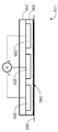
도 2는 본 발명의 일 실시예에 따른 햅틱 출력 디바이스(170)의 단면을 개략적으로 예시한다. 햅틱 출력 디바이스(170)의 제조는 아래에 더 상세하게 설명되는 바와 같이 전기 패터닝(electro-patterning) 및 표면 엔지니어링을 수반한다. 예시된 바와 같이, 햅틱 출력 디바이스(170)는 기판(210); 기판(210)의 상부 표면 상에 배치된 복수의 전극(220, 222, 224); 전극들(220, 222, 224) 사이에 그리고 상에 배치된 유전체 재료 층(230); 및 기판(210)에 대향하는 유전체 재료(230)의 측 상의 마이크로-패터닝된 외측 표면(240)을 포함한다. 전극들(220, 222, 224)은 제어기(120)에 의해 제어될 수 있는 전압 소스(V)와 신호 통신한다. 도 3은 마이크로-패터닝된 외측 표면(240)의 일부의 더 상세한 도면을 예시한다.Figure 2 schematically illustrates a cross-section of a
기판(210)은, 예를 들어 유기 절연체, 무기 절연체, 폴리디메틸실록산(PDMS), 폴리비닐리덴 플루오라이드(PVDF), 폴리에틸렌 테레프탈레이트(PET), 폴리스티렌(PS), 폴리프로필렌(PP) 등으로 이루어진 박형 및/또는 가요성 폴리머 필름, 또는 얇은 실리콘 층일 수 있다. 형상이 원형 또는 직사각형인 더 큰 전극들의 어레이의 일부일 수 있는 전극들(220, 222, 224)은 스퍼터링 또는 기상 증착 방법들을 이용하여 기판(210) 상에 패터닝될 수 있다. Au, Al, Cr, Cu, Ag, 탄소 나노튜브, 흑연, 반도체 등과 같은 상이한 전도성 금속들이 전극들(220, 222, 224)에 이용될 수 있다. 유전체 재료(230)는 기판(210) 및 전극들(220, 222, 224) 상으로 퇴적될 수 있다. 일 실시예에서, 유전체 재료(230)는 전극들(220, 222, 224)을 캡슐화할 수 있다. 유전체 재료 층(230)은 파릴렌, 실리콘 이산화물 등과 같은 유전체 재료를 포함할 수 있다.The
유전체 재료 층(230)의 외측 표면(240)의 유효 표면적을 증가시키기 위해서, 외측 표면(240)은 이온 빔 융합, 소프트 리소그래피 또는 마이크로-제조 기술, 예컨대 포지티브 및 네거티브 몰딩 기술, 캐스팅 기술, 또는 레이저 에칭 등과 같은 표면 에칭 기술을 이용함으로써 마이크로-패터닝될 수 있다. 이러한 기술들은 플라스틱(전도성 또는 비전도성) 또는 금속으로부터 나노/마이크로-패터닝된 표면들을 생성하는데 이용될 수 있다. 이러한 기술들은 직접 유전체 재료 층(230)에, 또는 다음에 유전체 재료 층(230)에 본딩되거나 접착될 수 있는 별개의 기판에 적용될 수 있다. 햅틱 출력 디바이스(170)의 일 실시예를 제조하는데 이용될 수 있는 제조 기술의 일례는, Journal of the Royal Society Interface 11: 20131089 (2014)에서 D. Ruffatto III 등에 의한 "Improving controllable adhesion on both rough and smooth surfaces with a hybrid electrostatic/gecko-like adhesive"에 기재되어 있으며, 이는 본 명세서에 참조로 완전히 포함되어 있다. 외측 표면(240)에 생성된 마이크로구조는 도 3에 예시된 바와 같이 복수의 마이크로웨지를 포함할 수 있다. 일 실시예에서, 마이크로구조는 복수의 원섬유 또는 높은 표면적을 갖는 다른 요소들을 포함할 수 있다. 일 실시예에서, 마이크로구조는 도마뱀의 발의 마이크로구조를 닮도록 구성되며, 도마뱀-유사 마이크로구조인 것으로 고려될 수 있다.To increase the effective surface area of the
마이크로-패터닝된 표면(240)이 유전체 재료 층(230)에 생성되지 않는 실시예들에서, 매우 얇은 유전체 재료 층이 절연체로서 표면 상에 퇴적될 수 있다. 외측 표면(240)을 마이크로(또는 나노)-패터닝함으로써, 외측 표면(240)과 이 외측 표면(240)에 접촉하는 다른 표면(250) 사이의 상호작용은 전극들(220, 222, 224)에 전기장을 인가하지 않으면서 증가될 수 있다. 패터닝은 다면체, 마이크로 필러, 구형 도트 등과 같은 피처들을 포함할 수 있다.In embodiments where the
도 2 및 도 3에 관련된 또 다른 실시예에서, 본 명세서에 설명된 바와 같은 2개의 접촉 영역 사이의 접촉 영역을 증가시키기 위한 표면 패터닝에 추가하여 또는 이러한 표면 패터닝을 대신하여, 인가된 전압을 증가시킴으로써 유사한 또는 개선된 효과를 달성할 수 있고, 따라서 2개의 접촉 영역 사이의 인력을 효과적으로 증가시킬 수 있다. 전압은 유전체 재료의 두께 및 유전 강도 값에 종속하여 수백 내지 수천 볼트의 범위에 있을 수 있다. 일반적으로, 전압이 높을수록, 힘이 커진다.In another embodiment related to Figures 2 and 3, in addition to or in place of surface patterning to increase the contact area between two contact areas as described herein, the applied voltage is increased To achieve a similar or improved effect, thereby effectively increasing the attractive force between the two contact areas. The voltage may range from hundreds to thousands of volts depending on the thickness of the dielectric material and the dielectric strength value. Generally, the higher the voltage, the greater the force.
전압 소스(V)에 의해 전극들(220, 222, 224)에 전압 전위가 제공될 때, 햅틱 출력 디바이스(170)의 외측 표면(240)과 이 외측 표면(240)에 접촉하는 표면(250) 사이에 정전기 부착력이 발생될 수 있고, 그에 의해 전자 디바이스(100)의 사용자는 햅틱 효과로서 표면들(240, 250) 사이의 부착의 증가를 느낄 수 있다.The
도 1로 복귀하면, 제어기(120)는 전자 디바이스(100)의 동작들과 기능들을 관리하거나 제어하기 위한 범용 또는 특정 목적 프로세서 또는 마이크로컨트롤러일 수 있다. 예를 들어, 제어기(120)는, 시각 정보를 제공하기 위해 디스플레이(160)에 대한 출력 신호들을 제어하고 햅틱 효과를 제공하기 위해 햅틱 출력 디바이스(170)에 대한 출력 신호들을 제어하도록 주문형 집적 회로("ASIC")로서 구체적으로 설계될 수 있다. 일부 실시예들에서, 제어기(120)는 햅틱 출력 디바이스(170)의 일부일 수 있다. 제어기(120)는, 미리 정의된 인자들에 기초하여, 발생될 햅틱 효과(들)의 타입(들), 햅틱 효과들이 발생되는 순서, 및 햅틱 효과들의 크기, 빈도(frequency), 지속기간 및/또는 다른 파라미터들을 결정하도록 구성될 수 있다. 제어기(120)는, 특정 햅틱 효과를 제공하기 위해 햅틱 출력 디바이스(170)를 구동하는데 이용될 수 있는 스트리밍 커맨드들을 제공하도록 또한 구성될 수 있다. 일부 실시예들에서, 제어기(120)는 실제로 전자 디바이스(100) 내에서 특정 기능들을 수행하도록 각각 구성되는 복수의 프로세서를 포함할 수 있다.Returning to FIG. 1, the
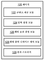
도 4는 제어기(120)의 일 실시예의 더 상세한 도면을 예시한다. 제어기(120)는 하나 이상의 컴퓨터 프로그램 모듈을 실행하도록 구성될 수 있다. 하나 이상의 컴퓨터 프로그램 모듈은 콘텐츠 제공 모듈(122), 입력 결정 모듈(124), 햅틱 효과 결정 모듈(126), 햅틱 출력 디바이스 제어 모듈(128) 및/또는 다른 모듈들 중 하나 이상을 포함할 수 있다. 제어기(120)는 소프트웨어, 하드웨어, 펌웨어, 소프트웨어, 하드웨어 및/또는 펌웨어의 소정의 조합, 및/또는 제어기(120) 상에 처리 능력들을 구성하기 위한 다른 메커니즘들에 의해 모듈들(122, 124, 126 및/또는 128)을 실행하도록 구성될 수 있다.FIG. 4 illustrates a more detailed view of one embodiment of
모듈들(122, 124, 126 및 128)은 단일 처리 유닛 내에 공존하는 것으로서 도 4에 예시되어 있지만, 제어기(120)가 다수의 처리 유닛을 포함하는 실시예들에서, 모듈들(122, 124, 126 및/또는 128) 중 하나 이상은 다른 모듈로부터 원격에 위치될 수 있다는 점이 인식되어야 한다. 아래에 설명되는 상이한 모듈들(122, 124, 126 및/또는 128)에 의해 제공되는 기능성의 설명은 예시적인 목적을 위한 것이며, 제한하는 것으로 의도되지는 않는데, 그 이유는 모듈들(122, 124, 126 및/또는 128) 중 임의의 것이 설명된 것보다 더 많거나 더 적은 기능성을 제공할 수 있기 때문이다. 예를 들어, 모듈들(122, 124, 126 및/또는 128) 중 하나 이상은 제거될 수 있고, 그것의 기능성의 일부 또는 전부는 모듈들(122, 124, 126 및/또는 128) 중 다른 모듈들에 의해 제공될 수 있다. 다른 예로서, 제어기(120)는 모듈들(122, 124, 126 및/또는 128) 중 하나에 속하는 아래의 기능성의 일부 또는 전부를 수행할 수 있는 하나 이상의 추가적인 모듈을 실행하도록 구성될 수 있다.Although the modules 122, 124, 126, and 128 are illustrated in FIG. 4 as coexisting within a single processing unit, in embodiments in which the
콘텐츠 제공 모듈(122)은 디스플레이(160)를 통해 전자 디바이스(100)의 사용자에게 콘텐츠를 제공하는 것을 제어하도록 구성된다. 콘텐츠가 컴퓨터 발생 이미지들을 포함하는 경우, 콘텐츠 제공 모듈(122)은 디스플레이(160)를 통해 사용자에게 디스플레이하기 위한 이미지들 및/또는 뷰들을 발생시키도록 구성된다. 콘텐츠 또는 콘텐츠가 도출되는 정보는 콘텐츠 제공 모듈(122)에 의해 전자 스토리지(129)로부터 획득될 수 있는데, 전자 스토리지는 도 4에 예시된 바와 같이 제어기(120)의 일부일 수 있거나, 또는 도 1에 예시된 메모리 디바이스(130)의 일부와 같이 제어기(120)와는 별개일 수 있다.The content providing module 122 is configured to control providing content to a user of the
입력 결정 모듈(124)은 센서(150)로부터 입력 신호를 수신하도록 구성된다. 입력 신호는 센서(150)가 전자 디바이스(100)의 사용자의 액션을 검출할 때 발생되는데, 이는 사용자에 의한 터치 입력, 또는 사용자가 전자 디바이스에 접근하는 것, 즉 사용자가 센서(150)에 근접해 있다는 것을 센서(150)가 감지하는 것일 수 있다. 입력 결정 모듈(124)은, 의도적인 액션에 대응하는 미리 결정된 임계 강도와 입력 신호의 강도를 비교함으로써, 감지된 액션이 의도적인 액션인지 또는 단순히 부주의한 액션, 예컨대 센서(150)에 의한 사용자의 중요하지 않은 통과 또는 센서(150)에 대한 부주의한 터치인지를 결정하도록 구성될 수 있다. 입력 결정 모듈(124)은, 센서(150)에 입력을 제공하거나 전자 디바이스(100)를 향하여 액션을 취할 때 사용자에 의해 무엇이 의도되었는지를 결정하도록 또한 구성된다. 예를 들어, 사용자는 특정 기능이 전자 디바이스(100)에 의해 수행되어야 한다는 것을 표시하는 특정 제스처를 센서(150)에 대해 제공하거나 센서(150)의 특정 위치를 터치할 수 있다. 입력 결정 모듈(124)은 센서(150) 상의 터치 위치들 및 미리 결정된 제스처들의 라이브러리로 프로그래밍될 수 있고, 그에 의해 사용자가 센서(150) 상의 특정 위치를 터치하거나 센서(150)에 대해 제스처를 제공할 때, 입력 결정 모듈(124)은 대응하는 출력을 결정할 수 있다.Input determination module 124 is configured to receive an input signal from
예를 들어, 전자 디바이스(100)가 스마트폰의 형태로 이루어지는 일 실시예에서, 사용자는 자신의 손가락으로 센서(150) 상에 심볼을 그릴 수 있고, 입력 결정 모듈(124)은, 사용자가 스마트폰과 자유롭게 상호작용할 수 있도록 스마트폰을 잠금해제하는 것과 같은 특정 커맨드에 그려진 심볼이 대응한다는 것을 결정할 수 있다. 센서(150)가 근접 또는 프레즌스 센서인 실시예들에서, 결정 모듈(124)은, 사용자가 센서(150)에 근접해 있다는 것을 센서(150)가 감지하는 시간의 지속기간에 기초하여 대응하는 출력을 결정하도록 프로그래밍될 수 있다.For example, in one embodiment where the
일 실시예에서, 입력 결정 모듈(124)은, 센서(150)로부터 수신되는 신호 대신에 또는 이러한 신호에 추가하여, 햅틱 효과가 발생되어야 한다는 것을 표시하는 입력을 제공하는 타이머와 같은 원격 디바이스로부터 신호를 수신하도록 구성될 수 있다. 추가로, 입력 결정 모듈(124)은, 입력이 검출되었고/되었거나 수락되었다는 것을 확인하는 햅틱 효과가 사용자에게 제공될 수 있도록 햅틱 효과 결정 모듈(126) 및/또는 햅틱 출력 디바이스 제어 모듈(128)에 신호를 또한 출력할 수 있다.In one embodiment, the input determination module 124 receives signals from a remote device, such as a timer, that provides an input that indicates that a haptic effect should be generated instead of, or in addition to, As shown in FIG. Additionally, the input determination module 124 may determine whether the input has been detected and / or accepted by the haptic effect determination module 126 and / or the haptic output device control module 128 so that a haptic effect can be provided to the user The signal can also be output.
햅틱 효과 결정 모듈(126)은, 햅틱 출력 디바이스(170)에 의해 발생되어 전자 디바이스(100)의 사용자에게 출력될 햅틱 효과 또는 감각을 결정하도록 구성된다. 햅틱 효과를 결정하는 것은 햅틱 효과의 타입, 및 진폭, 빈도, 지속기간 등과 같은 햅틱 효과의 하나 이상의 파라미터를 결정하는 것을 포함할 수 있다.The haptic effect determination module 126 is configured to determine a haptic effect or sensation to be generated by the
햅틱 출력 디바이스 제어 모듈(128)은 햅틱 효과 결정 모듈(126)에 의해 결정된 햅틱 효과를 발생시키게 햅틱 출력 디바이스(170)를 제어하도록 구성된다. 이것은 제어기(120)에 의해 발생된 햅틱 출력 신호를 버스(140)를 통해 햅틱 출력 디바이스(170)로 전달하는 것을 포함한다. 일 실시예에서, 햅틱 출력 디바이스 제어 모듈(128)에 속하는 기능성의 적어도 일부는 햅틱 출력 디바이스(170)에 의해 소지되는 제어기나 프로세서에 배치될 수 있다.The haptic output device control module 128 is configured to control the
본 발명의 실시예들에 따른 햅틱 출력 디바이스(170)는 다양한 구현예들에 있어서 전자 디바이스(100)에서 이용될 수 있다. 일 실시예에서, 센서(150)는, 햅틱 효과를 생성하기 위해 햅틱 출력 디바이스(170)에 의해 전기 부착이 활성화될 수 있도록, 햅틱 출력 디바이스(170)를 포함하는 전자 디바이스(100)를 향한 사용자의 액션을 검출하는데 이용될 수 있다. 예를 들어, 전자 디바이스(100)가 스마트폰이고, 스마트폰의 사용자가 스마트폰을 드래그하거나 리프트하고, 스마트폰과 이 스마트폰 밑의 접촉 표면 사이의 증가된 마찰/부착을 느낄 때, 햅틱 효과는 읽지 않은 이메일이나 텍스트 메시지 또는 부재중 통화가 존재한다는 것을 사용자에게 표시할 수 있다.The
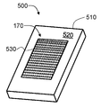
도 5에 예시된 전자 디바이스(500)의 일 실시예에서, 햅틱 출력 디바이스(170)는 전자 디바이스(500)를 위한 하우징(510) 또는 케이스에 적용될 수 있으며, 전자 디바이스(500)는 스마트폰일 수 있다. 예를 들어, 위에서 설명된 햅틱 출력 디바이스(170)는 패치(530)로서 전자 디바이스(500)의 하우징(510)의 후면(520) 상에 적용될 수 있다. 일 실시예에서, 전자 디바이스(500)의 사용자는, 사용자가 전자 디바이스(500)를 잡을 때 전자 디바이스(500)와 하부의 접촉 표면 사이의 증가된 부착을 느낄 수 있는데, 이는 예를 들어 사용자가 새로운 이메일이나 텍스트 메시지를 수신하였다는 것을 의미한다. 일 실시예에서, 전자 디바이스(500)의 사용자는 패치(530)를 직접 터치하고, 사용자가 전자 디바이스를 잡을 때 전자 디바이스(500)와 사용자의 피부 사이의 증가된 부착을 느낄 수 있는데, 이는 예를 들어 사용자가 새로운 이메일이나 텍스트 메시지를 수신하였다는 것을 의미한다.In one embodiment of the
일 실시예에서, 햅틱 출력 디바이스(170)는 하우징을 위한 커버의 내부 표면에 제공될 수 있고, 사용자가 커버를 열려고 시도하고 커버와 하우징 또는 스마트폰 사이의 증가된 부착을 느낄 때, 자신이 새로운 이메일이나 텍스트 메시지를 갖거나 또는 부재중 통화를 갖고 있다는 것이 사용자에게 통지될 수 있다.In one embodiment, the
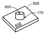
도 6에 예시된 일 실시예에서, 햅틱 출력 디바이스(170)는 하부의 표면과의 로터리 노브(600)의 마찰/부착을 제어하기 위해 로터리 노브(600)와 함께 구현될 수 있다. 예시된 실시예에서, 햅틱 출력 디바이스(170)는 로터리 노브(600) 밑의 하우징(620)의 상부 표면(610) 상에 제공된다. 일 실시예에서, 햅틱 출력 디바이스(170)는 로터리 노브(600)의 외측 표면에 제공될 수 있다. 로터리 노브(600)를 돌리는 사용자에게 제공되는 햅틱 효과는 사용자가 로터리 노브(600)를 잘못된 방향으로 돌릴 때 증가된 부착/마찰의 형태로 이루어질 수 있다. 다른 햅틱 효과들은 멈춤쇠(detents), 배리어 및 범프를 포함한다.6, the
일 실시예에서, 햅틱 출력 디바이스(170)는 사용자가 랩톱을 열 때 랩톱의 베이스 부분과의 부착을 제어하기 위해 랩톱 스크린의 코너들 상에 적용될 수 있다. 사용자가 햅틱 출력 디바이스(170)에 의해 제공되는 저항을 느낄 때, 사용자는 자신이 이메일 초안작성을 완료하지 않았거나 이메일을 송신하기 위한 송신 버튼을 누르는 것을 잊어버렸다는 것을 인식할 수 있다. 일 실시예에서, 햅틱 출력 디바이스(170)는, 마우스 패드 또는 지지 표면과의 부착이 사용자에 대해 햅틱 효과를 발생시키기 위해 제어될 수 있도록 컴퓨터 마우스 밑에 구현될 수 있다. 본 발명의 실시예들은, 햅틱 출력 디바이스(170)에 접촉하는 표면과 전자 디바이스 사이의 부착/마찰을 제어하는 것이 사용자에게 통지들을 제공하는데 이용될 수 있도록 전자 디바이스에서 서로에 대해 1개의 또는 2개의 부분을 이동(예를 들어, 상향 및 하향, 슬라이딩, 폴딩, 리프팅, 드래깅 등)시킬 필요가 있는 애플리케이션들에서 구현될 수 있다.In one embodiment, the
위에서 설명된 햅틱 출력 디바이스(170)에 추가하여, 전자 디바이스(100)는 입/출력 디바이스들(110)의 일부로서 다수의 햅틱 출력 디바이스를 포함할 수 있고, 진동, 변형, 운동 감각, 정전기 또는 초음파 마찰 등과 같은 햅틱 효과들을 생성하는 방법들 중 임의의 것으로 추가적인 햅틱 피드백이 생성될 수 있다. 일 실시예에서, 추가적인 햅틱 출력 디바이스는 액추에이터, 예를 들어 모터에 의해 편심 질량이 이동되는 편심 회전 질량("ERM"), 스프링에 부착된 질량이 앞뒤로 구동되는 선형 공진 액추에이터("LRA"), 또는 "스마트 재료", 예컨대 압전 재료들, 전기 활성 폴리머들, 예컨대 이온 또는 전자 기반 전기 활성 폴리머들, 형상 기억 재료들, 스마트 하이드로겔, 매크로컴포지트 섬유 액추에이터(macrocomposite fiber actuator), 정전 액추에이터, 전기 촉각 액추에이터, 나노컴포지트 액추에이터, 공압 기반 액추에이터, 및/또는 진동 촉각 피드백과 같은 물리적 피드백을 제공하는 다른 타입의 액추에이터를 포함할 수 있다. 추가적인 햅틱 출력 디바이스는, 정전기 마찰(ESF), 초음파 마찰(USF)을 이용하는 것들, 또는 초음파 햅틱 트랜스듀서로 음향 방사 압력을 유도하는 것들, 또는 햅틱 기판 및 가요성 또는 변형가능 표면을 이용하는 것들, 또는 열 효과들을 제공하는 것들, 또는 에어 제트 등을 이용하는 에어 퍼프와 같은 프로젝션형 햅틱 출력을 제공하는 것들과 같은 비기계식 또는 비진동식 디바이스들을 포함할 수 있다.In addition to the
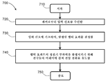
도 7은 본 발명의 실시예들에 따라 위에서 설명된 햅틱 출력 디바이스(170)와 같은 햅틱 출력 디바이스를 이용하여 햅틱 효과를 발생시키기 위한 방법(700)을 예시한다. 예시된 바와 같이, 이 방법은 710에서 시작한다. 720에서, 이 방법은, 제어기를 이용하여, 전자 디바이스의 사용자의 액션을 감지하도록 구성된 센서로부터 입력 신호를 수신하는 것을 포함한다. 센서는 위에서 설명된 센서(150)일 수 있고, 제어기는 위에서 설명된 제어기(120)일 수 있다. 730에서, 이 방법은, 제어기를 이용하여, 입력 신호에 기초하여, 햅틱 출력 디바이스에 의해 발생될 햅틱 효과를 결정하는 것을 포함한다. 740에서, 이 방법은, 햅틱 효과로서 햅틱 출력 디바이스의 노출된 외측 표면과 접촉 표면 사이에 정전기 부착력을 발생시키기 위해 햅틱 출력 디바이스의 전극들의 어레이에 걸쳐 전압 전위를 유도하는 것을 포함한다. 이 방법은 750에서 종료한다. 일 실시예에서, 이 방법은, 제어기를 이용하여, 전자 디바이스가 이메일이나 텍스트 메시지를 수신하였다는 표시를 수신하는 것을 또한 포함하고, 햅틱 효과는 이 표시 및 입력 신호에 기초하여 제어기에 의해 결정된다.Figure 7 illustrates a
정전기 부착성 기반 햅틱 출력 디바이스, 및 정전기 부착성 기반 햅틱 출력 디바이스를 통합하는 전자 디바이스의 다른 실시예들은, 확인 효과로서, 접촉 표면들에 있을 수 있다. 일례에서, 사용자가 터치 감응 표면을 터치할 때, 사용자 액션을 확인하기 위해서, 효과가 활성화되고, 사용자는 점착성 표면을 느끼거나 또는 상호작용이 등록되지 않은 경우에는 아무것도 느끼지 않을 것이다.Other embodiments of an electronic device incorporating an electrostaticattachment-based haptic output device and an electrostaticattachment-based haptic output device may be at the contact surfaces as an identification effect. In one example, when the user touches the touch sensitive surface, the effect is activated to confirm the user action, and the user will feel nothing if the user feels the sticky surface or the interaction is not registered.
본 명세서에 설명된 실시예들은 다수의 가능한 구현예들 및 예들을 나타내며, 반드시 본 개시내용을 임의의 특정 실시예들로 제한하는 것으로 의도되지는 않는다. 본 기술분야의 통상의 기술자에 의해 이해되는 바와 같이 이러한 실시예들에 대해 다양한 수정들이 이루어질 수 있다. 임의의 이러한 수정들은 본 개시내용의 사상 및 범위 내에 포함되며 다음의 청구항들에 의해 보호되는 것으로 의도된다.The embodiments described herein represent a number of possible implementations and examples, and are not intended to limit the present disclosure to any particular embodiment. Various modifications may be made to these embodiments as would be understood by one of ordinary skill in the art. Any such modifications are intended to be included within the spirit and scope of the present disclosure and protected by the following claims.
본 출원에 언급된 미국 특허들 및 미국 특허 출원 공개 공보들 모두는 본 명세서에 완전히 포함되어 있다.All of the US patents and U.S. patent application publications referred to in this application are fully incorporated herein.
Claims (17)
기판;
상기 기판 상에 배치된 전극들의 어레이;
상기 전극들의 어레이 상에 배치된 유전체 재료의 층 - 상기 유전체 재료의 층은 노출된 외측 표면을 갖고, 상기 노출된 외측 표면은, 상기 노출된 외측 표면과 상기 노출된 외측 표면에 접촉하는 접촉 표면 사이의 부착을 증가시키도록 구성된 마이크로-패터닝된 텍스처(micro-patterned texture)를 포함함 -; 및
햅틱 효과로서 상기 노출된 외측 표면과 상기 접촉 표면 사이에 정전기 부착력(electrostatic adhesive force)을 발생시키기 위해 상기 전극들의 어레이에 걸쳐 전압 전위를 유도하도록 구성된 제어기
를 포함하는 햅틱 출력 디바이스.1. A haptic output device,
Board;
An array of electrodes disposed on the substrate;
A layer of dielectric material disposed on the array of electrodes, the layer of dielectric material having an exposed outer surface, wherein the exposed outer surface is between an exposed outer surface and a contact surface that contacts the exposed outer surface A micro-patterned texture configured to increase adhesion of the substrate to the substrate; And
A controller configured to induce a voltage potential across the array of electrodes to generate an electrostatic adhesive force between the exposed outer surface and the contact surface as a haptic effect,
The haptic output device comprising:
상기 기판은, 폴리메틸실록산, 폴리비닐리덴 플루오라이드, 폴리에틸렌 테레프탈레이트, 폴리스티렌, 폴리프로필렌 및 이들의 조합으로 구성된 그룹으로부터 선택되는 재료를 포함하는 햅틱 출력 디바이스.The method according to claim 1,
Wherein the substrate comprises a material selected from the group consisting of polymethylsiloxane, polyvinylidene fluoride, polyethylene terephthalate, polystyrene, polypropylene, and combinations thereof.
상기 기판은 가요성 필름인 햅틱 출력 디바이스.The method according to claim 1,
Wherein the substrate is a flexible film.
상기 유전체 재료의 층은, 파릴렌, 실리콘 이산화물, 유기 절연체, 무기 절연체 및 이들의 조합으로 구성된 그룹으로부터 선택되는 유전체 재료를 포함하는 햅틱 출력 디바이스.The method according to claim 1,
Wherein the layer of dielectric material comprises a dielectric material selected from the group consisting of parylene, silicon dioxide, organic insulators, inorganic insulators, and combinations thereof.
상기 전자 디바이스의 사용자의 액션을 감지하도록 구성된 센서;
상기 센서에 의해 감지되는 상기 사용자의 액션에 응답하여, 햅틱 효과를 발생시키도록 구성된 햅틱 출력 디바이스 - 상기 햅틱 출력 디바이스는,
기판,
상기 기판 상에 배치된 전극들의 어레이, 및
상기 전극들의 어레이 상에 배치된 유전체 재료의 층
을 포함하고,
상기 유전체 재료의 층은 노출된 외측 표면을 갖고, 상기 노출된 외측 표면은, 상기 노출된 외측 표면과 상기 노출된 외측 표면에 접촉하는 접촉 표면 사이의 부착을 증가시키도록 구성된 마이크로-패터닝된 텍스처를 포함함 -; 및
상기 센서로부터 입력 신호를 수신하고, 상기 입력 신호에 기초하여 상기 햅틱 출력 디바이스에 의해 발생될 상기 햅틱 효과를 결정하고, 상기 햅틱 효과로서 상기 노출된 외측 표면과 상기 접촉 표면 사이에 정전기 부착력을 발생시키기 위해 상기 전극들의 어레이에 걸쳐 전압 전위를 유도하도록 구성된 제어기
를 포함하는 전자 디바이스.As an electronic device,
A sensor configured to sense an action of a user of the electronic device;
A haptic output device configured to generate a haptic effect in response to the action of the user as sensed by the sensor,
Board,
An array of electrodes disposed on the substrate, and
A layer of dielectric material disposed on the array of electrodes
/ RTI >
Wherein the layer of dielectric material has an exposed outer surface and the exposed outer surface comprises a micro-patterned texture configured to increase adhesion between the exposed outer surface and a contact surface contacting the exposed outer surface Included -; And
Receiving an input signal from the sensor, determining the haptic effect to be generated by the haptic output device based on the input signal, and generating an electrostatic adhesion force between the exposed outer surface and the contact surface as the haptic effect A controller configured to induce a voltage potential across the array of electrodes
≪ / RTI >
상기 센서는 근접 센서 또는 압력 센서인 전자 디바이스.6. The method of claim 5,
Wherein the sensor is a proximity sensor or a pressure sensor.
상기 기판은 열가소성 재료, 열경화성 재료, 엘라스토머 또는 이들의 조합을 포함하는 전자 디바이스.6. The method of claim 5,
Wherein the substrate comprises a thermoplastic material, a thermoset material, an elastomer, or a combination thereof.
상기 기판은 가요성 필름인 전자 디바이스.6. The method of claim 5,
Wherein the substrate is a flexible film.
상기 유전체 재료의 층은, 파릴렌이나 실리콘 이산화물을 포함하는 유전체 재료를 포함하는 전자 디바이스.6. The method of claim 5,
Wherein the layer of dielectric material comprises a dielectric material comprising parylene or silicon dioxide.
하우징을 더 포함하고, 상기 햅틱 출력 디바이스는 상기 하우징에 장착되는 전자 디바이스.6. The method of claim 5,
Further comprising a housing, wherein the haptic output device is mounted to the housing.
상기 햅틱 출력 디바이스는 상기 하우징의 외부 표면 상에 장착되는 전자 디바이스.11. The method of claim 10,
Wherein the haptic output device is mounted on an outer surface of the housing.
상기 전자 디바이스의 사용자에 의해 회전되도록 구성된 로터리 노브(rotary knob)를 더 포함하고, 상기 로터리 노브는 상기 접촉 표면을 포함하는 전자 디바이스.6. The method of claim 5,
Further comprising a rotary knob configured to be rotated by a user of the electronic device, wherein the rotary knob comprises the contact surface.
상기 제어기는, 상기 전자 디바이스가 이메일이나 텍스트 메시지를 수신하였다는 표시를 수신하고, 상기 표시 및 상기 입력 신호에 기초하여 상기 햅틱 효과를 결정하도록 추가로 구성되는 전자 디바이스.6. The method of claim 5,
Wherein the controller is further configured to receive an indication that the electronic device has received an email or text message and to determine the haptic effect based on the indication and the input signal.
제어기를 이용하여, 전자 디바이스의 사용자의 액션을 감지하도록 구성된 센서로부터 입력 신호를 수신하는 단계;
상기 제어기를 이용하여, 상기 입력 신호에 기초하여, 상기 햅틱 출력 디바이스에 의해 발생될 상기 햅틱 효과를 결정하는 단계; 및
상기 햅틱 효과로서 상기 햅틱 출력 디바이스의 노출된 외측 표면과 접촉 표면 사이에 정전기 부착력을 발생시키기 위해 상기 햅틱 출력 디바이스의 전극들의 어레이에 걸쳐 전압 전위를 유도하는 단계
를 포함하는 방법.CLAIMS 1. A method for generating a haptic effect using a haptic output device,
Using the controller, receiving an input signal from a sensor configured to sense an action of a user of the electronic device;
Using the controller to determine the haptic effect to be generated by the haptic output device based on the input signal; And
Inducing a voltage potential across the array of electrodes of the haptic output device to generate an electrostaticattress force between the exposed outer surface of the haptic output device and the contact surface as the haptic effect;
≪ / RTI >
상기 햅틱 출력 디바이스는 기판, 상기 기판 상에 배치된 상기 전극들의 어레이, 및 상기 전극들의 어레이 상에 배치된 유전체 재료의 층을 포함하고, 상기 유전체 재료의 층은 상기 노출된 외측 표면을 포함하고, 상기 노출된 외측 표면은, 상기 노출된 외측 표면과 상기 노출된 외측 표면에 접촉하는 상기 접촉 표면 사이의 부착을 증가시키도록 구성된 마이크로-패터닝된 텍스처를 포함하는 방법.15. The method of claim 14,
The haptic output device comprising a substrate, an array of electrodes disposed on the substrate, and a layer of dielectric material disposed on the array of electrodes, the layer of dielectric material including the exposed outer surface, Wherein the exposed outer surface comprises a micro-patterned texture configured to increase adhesion between the exposed outer surface and the contact surface contacting the exposed outer surface.
상기 제어기를 이용하여, 상기 전자 디바이스가 이메일이나 텍스트 메시지를 수신하였다는 표시를 수신하는 단계를 더 포함하고, 상기 햅틱 효과는 상기 표시 및 상기 입력 신호에 기초하여 상기 제어기에 의해 결정되는 방법.16. The method of claim 15,
Using the controller, further comprising receiving an indication that the electronic device has received an e-mail or text message, the haptic effect being determined by the controller based on the indication and the input signal.
상기 재료는, 폴리메틸실록산, 폴리비닐리덴 플루오라이드, 폴리에틸렌 테레프탈레이트, 폴리스티렌, 폴리프로필렌 및 이들의 조합으로 구성된 그룹으로부터 선택되는 전자 디바이스.8. The method of claim 7,
Wherein the material is selected from the group consisting of polymethylsiloxane, polyvinylidene fluoride, polyethylene terephthalate, polystyrene, polypropylene, and combinations thereof.
Applications Claiming Priority (2)
| Application Number | Priority Date | Filing Date | Title |
|---|---|---|---|
| US15/072,485 US10042424B2 (en) | 2016-03-17 | 2016-03-17 | Electrostatic adhesive based haptic output device |
| US15/072,485 | 2016-03-17 |
Publications (1)
| Publication Number | Publication Date |
|---|---|
| KR20170108882A true KR20170108882A (en) | 2017-09-27 |
Family
ID=58398027
Family Applications (1)
| Application Number | Title | Priority Date | Filing Date |
|---|---|---|---|
| KR1020170033704A KR20170108882A (en) | 2016-03-17 | 2017-03-17 | Electrostatic adhesive based haptic output device |
Country Status (5)
| Country | Link |
|---|---|
| US (2) | US10042424B2 (en) |
| EP (1) | EP3220236B1 (en) |
| JP (1) | JP2017168104A (en) |
| KR (1) | KR20170108882A (en) |
| CN (1) | CN107203262A (en) |
Families Citing this family (13)
| Publication number | Priority date | Publication date | Assignee | Title |
|---|---|---|---|---|
| US10210978B2 (en) * | 2017-01-26 | 2019-02-19 | Immersion Corporation | Haptic actuator incorporating conductive coil and moving element with magnets |
| US10996755B2 (en) | 2018-02-28 | 2021-05-04 | Google Llc | Piezoelectric haptic feedback module |
| US10613626B2 (en) | 2018-06-15 | 2020-04-07 | Immersion Corporation | Kinesthetically enabled glove |
| CN108845715A (en) * | 2018-09-05 | 2018-11-20 | 业成科技(成都)有限公司 | The manufacturing method of touch control display apparatus and touch control display apparatus |
| TR201905624A2 (en) | 2019-04-16 | 2019-07-22 | Hidropar Hareket Kontrol Teknolojileri Merkezi Sanayi Ve Ticaret Anonim Sirketi | The method of creating a controllable electrostatic attraction force between two bodies and providing adhesion with the help of this attraction force. |
| WO2021007223A1 (en) * | 2019-07-07 | 2021-01-14 | Selfie Snapper, Inc. | Selfie camera |
| JPWO2021048998A1 (en) * | 2019-09-13 | 2021-03-18 | ||
| WO2021111577A1 (en) * | 2019-12-05 | 2021-06-10 | 三菱電機株式会社 | Tactile presentation panel, tactile presentation touch panel, tactile presentation touch display, and tactile presentation knob |
| JP6804697B1 (en) * | 2019-12-26 | 2020-12-23 | 三菱電機株式会社 | Tactile presentation control device, tactile presentation panel, tactile presentation touch panel, and tactile presentation touch display |
| WO2021130971A1 (en) * | 2019-12-26 | 2021-07-01 | 三菱電機株式会社 | Tactile presentation panel and tactile presentation knob |
| US11747907B2 (en) * | 2020-01-07 | 2023-09-05 | Mitsubishi Electric Corporation | Tactile presentation panel, tactile presentation touch panel, and tactile presentation touch display |
| CN113247136B (en) * | 2021-05-27 | 2022-07-12 | 南京航空航天大学 | Bionic adhesion part driven by solid-liquid mixing and with controllable adhesion-desorption |
| WO2024028998A1 (en) * | 2022-08-03 | 2024-02-08 | 三菱電機株式会社 | Tactile-sensation-imparting device |
Family Cites Families (11)
| Publication number | Priority date | Publication date | Assignee | Title |
|---|---|---|---|---|
| CN101934659A (en) * | 2010-07-23 | 2011-01-05 | 欧朋达科技(深圳)有限公司 | Roughing treatment and print process of metal surface |
| US20130186699A1 (en) | 2012-01-23 | 2013-07-25 | Sri International | High voltage converters for electrostatic applications |
| US20140368993A1 (en) * | 2013-06-18 | 2014-12-18 | Nvidia Corporation | Using synthetic setae on mobile device housing |
| WO2014209405A1 (en) * | 2013-06-29 | 2014-12-31 | Intel Corporation | System and method for adaptive haptic effects |
| EP2866165B1 (en) * | 2013-10-28 | 2018-12-05 | LG Electronics Inc. -1- | Mobile terminal and controlling method thereof |
| US20160318190A1 (en) * | 2013-12-20 | 2016-11-03 | Grabit, Inc. | Modular electroadhesive gripping system |
| US10031582B2 (en) * | 2014-06-05 | 2018-07-24 | Immersion Corporation | Systems and methods for induced electrostatic haptic effects |
| US9606624B2 (en) | 2014-07-02 | 2017-03-28 | Immersion Corporation | Systems and methods for surface elements that provide electrostatic haptic effects |
| CN204020107U (en) * | 2014-07-23 | 2014-12-17 | 苏州斯迪克新材料科技股份有限公司 | A kind of printable scratch resistant Antistatic protective film |
| KR102560704B1 (en) * | 2015-02-17 | 2023-07-28 | 삼성디스플레이 주식회사 | Display apparatus and method for manufacturing display apparatus |
| WO2016205713A1 (en) * | 2015-06-19 | 2016-12-22 | Northwestern University | Apparatus for unified audio tactile feedback |
-
2016
- 2016-03-17 US US15/072,485 patent/US10042424B2/en not_active Expired - Fee Related
-
2017
- 2017-03-16 EP EP17161275.7A patent/EP3220236B1/en active Active
- 2017-03-17 JP JP2017052071A patent/JP2017168104A/en not_active Withdrawn
- 2017-03-17 CN CN201710159183.5A patent/CN107203262A/en active Pending
- 2017-03-17 KR KR1020170033704A patent/KR20170108882A/en active Search and Examination
-
2018
- 2018-08-06 US US16/055,822 patent/US10452146B2/en not_active Expired - Fee Related
Also Published As
| Publication number | Publication date |
|---|---|
| US10452146B2 (en) | 2019-10-22 |
| US20180348874A1 (en) | 2018-12-06 |
| EP3220236A1 (en) | 2017-09-20 |
| US10042424B2 (en) | 2018-08-07 |
| CN107203262A (en) | 2017-09-26 |
| EP3220236B1 (en) | 2019-10-30 |
| US20170269686A1 (en) | 2017-09-21 |
| JP2017168104A (en) | 2017-09-21 |
Similar Documents
| Publication | Publication Date | Title |
|---|---|---|
| US10452146B2 (en) | Electrostatic adhesive based haptic output device | |
| US10564727B2 (en) | Systems and methods for a low profile haptic actuator | |
| CN104679233B (en) | System and method for generating friction and vibration sense of touch effect | |
| US9898903B2 (en) | Systems and methods for haptic surface elements | |
| US9875625B2 (en) | Systems and methods for multifunction haptic output devices | |
| US8421610B2 (en) | Touch screen and method of operating the same | |
| EP2778847B1 (en) | Contactor-based haptic feedback generation | |
| JP6392747B2 (en) | Display device | |
| CN104881175B (en) | Multi-touch device with dynamic haptic effects | |
| US8570296B2 (en) | System and method for display of multiple data channels on a single haptic display | |
| JP7210603B2 (en) | Systems and methods for detecting and responding to touch input using haptic feedback | |
| JP2016219002A (en) | Haptic effects based on predicted contact | |
| EP3425482A2 (en) | Active matrix haptic feedback | |
| CN108279770A (en) | For the system and method based on close touch feedback | |
| KR20110093553A (en) | Apparatus and method for providing touch and sight sensation information | |
| Farooq et al. | Haptic user interface enhancement system for touchscreen based interaction | |
| EP3391185A1 (en) | Low-profile pointing stick | |
| JP2022051431A (en) | Pressure sensitive input device | |
| KR20100064493A (en) | Haptic apparatus for providing feedback and method for providing haptic feedback using the same |
Legal Events
| Date | Code | Title | Description |
|---|---|---|---|
| A201 | Request for examination |