KR20170104865A - Real-time Identifying User Location System based on wrist type band - Google Patents
Real-time Identifying User Location System based on wrist type band Download PDFInfo
- Publication number
- KR20170104865A KR20170104865A KR1020160027836A KR20160027836A KR20170104865A KR 20170104865 A KR20170104865 A KR 20170104865A KR 1020160027836 A KR1020160027836 A KR 1020160027836A KR 20160027836 A KR20160027836 A KR 20160027836A KR 20170104865 A KR20170104865 A KR 20170104865A
- Authority
- KR
- South Korea
- Prior art keywords
- cpu
- wrist
- signal
- wrist band
- band
- Prior art date
Links
Images

Classifications
-
- H—ELECTRICITY
- H04—ELECTRIC COMMUNICATION TECHNIQUE
- H04W—WIRELESS COMMUNICATION NETWORKS
- H04W64/00—Locating users or terminals or network equipment for network management purposes, e.g. mobility management
-
- G—PHYSICS
- G01—MEASURING; TESTING
- G01S—RADIO DIRECTION-FINDING; RADIO NAVIGATION; DETERMINING DISTANCE OR VELOCITY BY USE OF RADIO WAVES; LOCATING OR PRESENCE-DETECTING BY USE OF THE REFLECTION OR RERADIATION OF RADIO WAVES; ANALOGOUS ARRANGEMENTS USING OTHER WAVES
- G01S1/00—Beacons or beacon systems transmitting signals having a characteristic or characteristics capable of being detected by non-directional receivers and defining directions, positions, or position lines fixed relatively to the beacon transmitters; Receivers co-operating therewith
- G01S1/02—Beacons or beacon systems transmitting signals having a characteristic or characteristics capable of being detected by non-directional receivers and defining directions, positions, or position lines fixed relatively to the beacon transmitters; Receivers co-operating therewith using radio waves
- G01S1/04—Details
- G01S1/042—Transmitters
-
- G—PHYSICS
- G08—SIGNALLING
- G08B—SIGNALLING OR CALLING SYSTEMS; ORDER TELEGRAPHS; ALARM SYSTEMS
- G08B21/00—Alarms responsive to a single specified undesired or abnormal condition and not otherwise provided for
- G08B21/02—Alarms for ensuring the safety of persons
- G08B21/0202—Child monitoring systems using a transmitter-receiver system carried by the parent and the child
- G08B21/0272—System arrangements wherein the object is to detect exact location of child or item using triangulation other than GPS
-
- G—PHYSICS
- G08—SIGNALLING
- G08B—SIGNALLING OR CALLING SYSTEMS; ORDER TELEGRAPHS; ALARM SYSTEMS
- G08B21/00—Alarms responsive to a single specified undesired or abnormal condition and not otherwise provided for
- G08B21/02—Alarms for ensuring the safety of persons
- G08B21/0202—Child monitoring systems using a transmitter-receiver system carried by the parent and the child
- G08B21/0277—Communication between units on a local network, e.g. Bluetooth, piconet, zigbee, Wireless Personal Area Networks [WPAN]
-
- G—PHYSICS
- G08—SIGNALLING
- G08B—SIGNALLING OR CALLING SYSTEMS; ORDER TELEGRAPHS; ALARM SYSTEMS
- G08B25/00—Alarm systems in which the location of the alarm condition is signalled to a central station, e.g. fire or police telegraphic systems
- G08B25/12—Manually actuated calamity alarm transmitting arrangements emergency non-personal manually actuated alarm, activators, e.g. details of alarm push buttons mounted on an infrastructure
-
- G—PHYSICS
- G08—SIGNALLING
- G08B—SIGNALLING OR CALLING SYSTEMS; ORDER TELEGRAPHS; ALARM SYSTEMS
- G08B3/00—Audible signalling systems; Audible personal calling systems
- G08B3/10—Audible signalling systems; Audible personal calling systems using electric transmission; using electromagnetic transmission
-
- G—PHYSICS
- G08—SIGNALLING
- G08B—SIGNALLING OR CALLING SYSTEMS; ORDER TELEGRAPHS; ALARM SYSTEMS
- G08B5/00—Visible signalling systems, e.g. personal calling systems, remote indication of seats occupied
- G08B5/22—Visible signalling systems, e.g. personal calling systems, remote indication of seats occupied using electric transmission; using electromagnetic transmission
-
- H04W4/008—
-
- H—ELECTRICITY
- H04—ELECTRIC COMMUNICATION TECHNIQUE
- H04W—WIRELESS COMMUNICATION NETWORKS
- H04W4/00—Services specially adapted for wireless communication networks; Facilities therefor
- H04W4/02—Services making use of location information
- H04W4/023—Services making use of location information using mutual or relative location information between multiple location based services [LBS] targets or of distance thresholds
-
- H—ELECTRICITY
- H04—ELECTRIC COMMUNICATION TECHNIQUE
- H04W—WIRELESS COMMUNICATION NETWORKS
- H04W88/00—Devices specially adapted for wireless communication networks, e.g. terminals, base stations or access point devices
- H04W88/02—Terminal devices
Abstract
Description
The present invention relates to a real-time position tracking system, and more particularly, to a real-time position tracking system in which a wrist band equipped with a temperature sensor, a position sensor, a three- To a technology that can cope with this problem.
Generally, in the Internet or mobile service based on subscription of a user, the conventional position tracking method is a GPS (Global Positioning System) system, which is a satellite navigation system that receives a signal transmitted from a GPS satellite and calculates a user's current position . This is mainly used for navigation devices such as aircraft, ships, and automobiles, and has recently been widely used in smartphones and tablet PCs.
However, due to the error range of the GPS system and the limitation of the location search, too many users are searched when the location tracking method is applied, so that there is a problem that it is difficult to select a user located near the location. That is, there is a problem that an error range is too large to measure and provide information of users located in a short distance.
Therefore, a beacon position transmitter has been developed to solve this problem, and it has a merit of being able to communicate with devices within a maximum distance of 70m using a Bluetooth 4.0 protocol based short range wireless communication device. It is highly accurate enough to be able to distinguish between 5 and 10cm units, and is suitable for Internet implementation of things that all devices are always connected because of low power consumption.
Various positioning systems combining beacon and LAN are being developed.
Typically, a LAN (Local Area Network) refers to a network connecting a small number of devices located at a relatively short distance, and generally refers to a network connecting one office, one or several adjacent buildings. Such a LAN network can literally be used efficiently when it is located at a close distance.
However, the conventional location tracking technology has a limitation in that it can grasp the current location of each user in a limited area because the smartphone carried by the individual and the beacons around the user track the location by interlocking with each other, There is a problem in that there is a limitation.
SUMMARY OF THE INVENTION Accordingly, the present invention has been made to solve the above-mentioned problems occurring in the prior art, and it is an object of the present invention to provide a beacon- And to provide a technique capable of responding appropriately.
It is an object of the present invention to provide a real-time location tracking system of this wearable type in an emergency such as an emergency relief through real-time positioning of miners in a mine, patient management and protection measures in case of an emergency through position control of a patient in a nursing home or hospital, , Asset management through real-time location control of cargo containers in large cargo spaces, reinforcement of alertness through real-time location control of soldiers on the move in the military boundary management system, In the case of ships, it is applied to specific restricted areas such as humanitarian relief measures through real-time location control within a limited area, thereby providing a technique to take necessary measures promptly in case of an emergency.
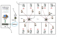
In order to achieve the above-mentioned object, a preferred embodiment of the present invention provides a real-time location tracking system comprising at least one location transmitter (5) placed in a building and emitting a location signal;
A wrist band (3) for receiving a position signal transmitted from the position transmitter (5) and recognizing the position;
At least one router (7) for transmitting a position signal received from the wrist band (3);
And a server (Server) 9 for processing signals received from the
The
A
The
The wrist-wearable real-time position tracking system according to the present invention has the following advantages.
First, the user wears a wearable band on his / her wrist, and this band is interlocked with beacons and routers in the vicinity, thereby being able to accurately grasp the current position in real time.
Second, the wrist band is provided with a temperature sensor, a three-axis sensor, a vibration motor, and an NFC chipset, thereby detecting the current temperature, position, and movement of the user in real time.
Third, real - time location tracking system can be applied to mines, hospitals, large cargo bases, elderly people living alone, military boundaries, nursing homes, etc.
Fourth, when wrist band is used for mining, moisture can be absorbed inside the band due to deep underground environment. By providing altimeter and heating system in the band, moisture can be removed by heat have.
Fifth, a real-time location tracking system using a wireless router can precisely detect and transmit a user's position signal over all areas in a space by attaching a position transmitter to all spaces capable of wireless communication within a large space, It becomes.
Sixth, in the case of a wired router using a LAN (Local Area Network), the problem is solved by solving the problem with complicated installation by solving the problem with a wireless router by installing a LAN line, thereby reducing the investment cost of the user, And it is possible to easily and extensively track where the user is located.
1 is a schematic view of a position tracking system according to an embodiment of the present invention.
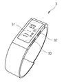
FIG. 2 is a perspective view showing the appearance of the wrist band shown in FIG. 1. FIG.
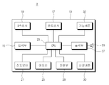
FIG. 3 is a schematic view showing the internal structure of the wrist band shown in FIG. 2. FIG.
FIG. 4 is a view showing a monitor screen form of a controller when the position tracking system shown in FIG. 1 is applied to a hospital.
Hereinafter, a real-time location tracking system according to an embodiment of the present invention will be described in detail.
1 to 3, the real-time location tracking system 1 proposed by the present invention comprises a
To describe this real-time location tracking system in more detail,
The
The wrist band (3) comprises a case (13) provided with a band (3) to be worn on the wrist; An
In the
The
The
The
The three-
The three-
If the
The
The
That is, the
More specifically, the
Therefore, the
Then, the
In other words, it is possible to clearly distinguish the case where there is no motion due to sleeping and the case where there is no motion due to an abnormality by setting the motion reference time of bedtime and daytime differently.
For example, if there is no movement for 10 minutes during the daytime, it is judged as abnormal, but if there is no movement for 1 hour at the bedtime, it is judged as abnormal.
Then, the
That is, in the above-mentioned case, if the sleeping time does not move for one hour, the abnormality is determined, and at the same time, the body temperature value is also calculated, and if the body temperature is lower than or equal to a certain range, an alarm signal is issued even after one hour has elapsed.
The
The
The
The user can see the character of the
An alarm button is disposed on one side of the
In addition, the
Near Field Communication (NFC) is a non-contact, short-range wireless communication module using 13.56Mhz frequency band, which means transmitting data at a distance of 10cm.
By mounting the NFC chipset on the
Then, the
The
The
Then, the
On the other hand, the
The
For example, to relay different local area networks (LANs) or to connect a local area network to a wide area network (WAN).
The
The
The
The
That is, when the emergency signal is received from the
Fig. 4 shows a screen format displayed on a monitor disposed in a control station, in which a real-time location tracking system of the present embodiment is applied to a hospital.
As shown in the figure, a patient room placed on each floor in a hospital building is shown, and patients worn with a
That is, when each patient moves in a building of a hospital with the
The
The
Therefore, the
For example, the patient is classified into a normal state, a non-working state, a non-wearing state, and a doctor calling state.
If it does not work, it can be regarded as a case where an abnormality occurs in the patient. In such a case, it is identified as an emergency situation and quick action is taken.
In addition, the
In this way, the current position and health status of each patient in the hospital can be grasped in real time so that appropriate emergency measures can be taken promptly.
The wrist band may be classified into a patient, a doctor, and a nurse.
That is, by inputting the user's ID to the memory of the wrist band and the CPU in advance, the server can recognize whether the person using the wrist band is a medical person such as a doctor or a nurse or a patient.
Therefore, the patient and the medical person can be identified based on the symbols displayed on the monitor of the server, and when an abnormality occurs in the patient, the adjacent medical person can be called.
Although the above-described position tracking system is applied to a hospital as an example, the present invention is not limited to this, and can be applied to various industrial fields.
For example, it can be applied to a mine, a route, a large cargo base, a specific restricted area, etc., so that it can quickly grasp the real time location and the like.
Particularly, when a wrist band is used for a mine, moisture may be caught inside the wrist band due to its deep underground environment.
Therefore, in order to remove such moisture, a depth measuring sensor and a heating member may be mounted on the wrist band.
That is, by attaching the depth measurement sensor to the wrist band and connecting it to the
As such, it is convenient to remove moisture even in a deep underground environment such as a mine.
Claims (9)
A wrist band (3) for receiving a position signal transmitted from the position transmitter (5) and recognizing the position;
At least one router (7) for transmitting a position signal received from the wrist band (3);
And a server (Server) 9 for processing signals received from the router 7 through the wireless LAN network 11,
The wrist band 3 is a mobile communication terminal worn by the user on the wrist,
A case 13 provided with a band 3 to be worn on the wrist, an input unit 15 mounted inside the case 13 for receiving a signal, a temperature sensor 17 for measuring a user's body temperature A CPU 23 for processing current position information and motion and temperature data in cooperation with the sensor and input unit 15; A memory 25 for storing data, an output unit 27 for transferring the result processed by the CPU 23 to the outside, and a power supply unit 29,
The wrist band (3) has a unique IP so that it can be identified.
The location transmitter (5) includes a beacon (5) and has a frequency band of 400 MHz.
An input unit (15) includes any one of an antenna for receiving a signal received from the beacon (5) and a function button arranged outside the case (13) to set a function.
The CPU 23 interlocks with the temperature sensor 17 and the three-axis sensor 19 to determine the presence or absence of an abnormality of the user's body temperature, system.
The CPU 23 further interlocks with the clock to grasp the body temperature of the user to judge whether or not an abnormality has occurred. If there is no movement from the three-axis sensor 19, the CPU 23 determines that the abnormality is abnormal, Real-time location tracking system to judge.
The output unit 27 includes an output port 30 for transmitting the result calculated by the CPU 23 to the outside and an output port 30 disposed on the front surface of the case 13 for displaying characters, 31), and a speaker (33) for generating a sound, a warning sound, and an operation sound.
The wrist band includes a depth measurement sensor for measuring the depth and transmitting a signal to the CPU;
And a heating member for generating heat by a signal of the CPU when the temperature is below a predetermined depth.
The wrist band (3) further includes an NFC chipset.
The wrist band (3) informs the emergency situation by additionally arranging an alarm button.
Priority Applications (1)
| Application Number | Priority Date | Filing Date | Title |
|---|---|---|---|
| KR1020160027836A KR20170104865A (en) | 2016-03-08 | 2016-03-08 | Real-time Identifying User Location System based on wrist type band |
Applications Claiming Priority (1)
| Application Number | Priority Date | Filing Date | Title |
|---|---|---|---|
| KR1020160027836A KR20170104865A (en) | 2016-03-08 | 2016-03-08 | Real-time Identifying User Location System based on wrist type band |
Publications (1)
| Publication Number | Publication Date |
|---|---|
| KR20170104865A true KR20170104865A (en) | 2017-09-18 |
Family
ID=60034569
Family Applications (1)
| Application Number | Title | Priority Date | Filing Date |
|---|---|---|---|
| KR1020160027836A KR20170104865A (en) | 2016-03-08 | 2016-03-08 | Real-time Identifying User Location System based on wrist type band |
Country Status (1)
| Country | Link |
|---|---|
| KR (1) | KR20170104865A (en) |
Cited By (3)
| Publication number | Priority date | Publication date | Assignee | Title |
|---|---|---|---|---|
| CN107995592A (en) * | 2017-12-25 | 2018-05-04 | 苏州赛源微电子有限公司 | A kind of WIFI wireless telecommunications personnel positioning management system |
| CN111383419A (en) * | 2019-12-03 | 2020-07-07 | 扬州后潮科技有限公司 | Prevent equipment of going astray from group |
| KR20220099231A (en) | 2021-01-06 | 2022-07-13 | (주)바이오스마트 | Location tracking wearable terminal for patients with dementia through credit card authentication and method of using the same |
-
2016
- 2016-03-08 KR KR1020160027836A patent/KR20170104865A/en active IP Right Grant
Cited By (3)
| Publication number | Priority date | Publication date | Assignee | Title |
|---|---|---|---|---|
| CN107995592A (en) * | 2017-12-25 | 2018-05-04 | 苏州赛源微电子有限公司 | A kind of WIFI wireless telecommunications personnel positioning management system |
| CN111383419A (en) * | 2019-12-03 | 2020-07-07 | 扬州后潮科技有限公司 | Prevent equipment of going astray from group |
| KR20220099231A (en) | 2021-01-06 | 2022-07-13 | (주)바이오스마트 | Location tracking wearable terminal for patients with dementia through credit card authentication and method of using the same |
Similar Documents
| Publication | Publication Date | Title |
|---|---|---|
| AU2021201818B2 (en) | Tracking and accountability device and system | |
| CA2720374C (en) | Position-monitoring device for persons | |
| KR100923294B1 (en) | Real-time position recognition method and system in a ubiquitous environment | |
| US20180072223A1 (en) | Impact prevention using mobile beacons | |
| US7584048B2 (en) | Portable positioning and navigation system | |
| TWI618375B (en) | A bluetooth personnel location system | |
| EP3710851B1 (en) | System and method for supervising a person | |
| US10410499B2 (en) | Identifying an identity of a person detected in a monitored location | |
| US20080122696A1 (en) | Low cost fire fighter tracking system | |
| KR101755533B1 (en) | Safety management system based on Internet of Things | |
| KR20190042632A (en) | Observation-based event tracking | |
| KR101697546B1 (en) | Security control system using beacon | |
| WO2016011507A1 (en) | Monitoring system, device, method, processing system, fall arrest equipment and kit for use with a fall arrest system | |
| KR20170104865A (en) | Real-time Identifying User Location System based on wrist type band | |
| CN104732682A (en) | Wearable fire fighting reminding device and escape reminding system | |
| KR101352945B1 (en) | System and method for tracking position and sensing action of a worker | |
| US9858791B1 (en) | Tracking and accountability device and system | |
| KR102582490B1 (en) | Apparatus and method for safety management | |
| Sammarco et al. | A technology review of smart sensors with wireless networks for applications in hazardous work environments | |
| US10546477B2 (en) | Method and system for monitoring the safety of field workers | |
| JP6955902B2 (en) | Transmitter maintenance and inspection support system | |
| KR101649191B1 (en) | Location Chasing Method using Motion Detecting Sensor and terminal using thereof | |
| US20170311123A1 (en) | Accessory Device for Geo-Localization and Proximity Detection in Industrial Applications and Methods for Operating Same | |
| JP2023172655A (en) | Safety monitoring device of indoor space, safety monitoring method of indoor space, and safety monitoring system of indoor space | |
| JP2019186783A (en) | Management system |
Legal Events
| Date | Code | Title | Description |
|---|---|---|---|
| A201 | Request for examination | ||
| E902 | Notification of reason for refusal | ||
| E701 | Decision to grant or registration of patent right |