KR20170104577A - Slot apparatus and method for cutting a groove of a sheet, - Google Patents
Slot apparatus and method for cutting a groove of a sheet, Download PDFInfo
- Publication number
- KR20170104577A KR20170104577A KR1020177022685A KR20177022685A KR20170104577A KR 20170104577 A KR20170104577 A KR 20170104577A KR 1020177022685 A KR1020177022685 A KR 1020177022685A KR 20177022685 A KR20177022685 A KR 20177022685A KR 20170104577 A KR20170104577 A KR 20170104577A
- Authority
- KR
- South Korea
- Prior art keywords
- knife
- head
- slatter
- slotter
- sheet
- Prior art date
Links
Images


Classifications
-
- B—PERFORMING OPERATIONS; TRANSPORTING
- B26—HAND CUTTING TOOLS; CUTTING; SEVERING
- B26D—CUTTING; DETAILS COMMON TO MACHINES FOR PERFORATING, PUNCHING, CUTTING-OUT, STAMPING-OUT OR SEVERING
- B26D1/00—Cutting through work characterised by the nature or movement of the cutting member or particular materials not otherwise provided for; Apparatus or machines therefor; Cutting members therefor
- B26D1/01—Cutting through work characterised by the nature or movement of the cutting member or particular materials not otherwise provided for; Apparatus or machines therefor; Cutting members therefor involving a cutting member which does not travel with the work
- B26D1/12—Cutting through work characterised by the nature or movement of the cutting member or particular materials not otherwise provided for; Apparatus or machines therefor; Cutting members therefor involving a cutting member which does not travel with the work having a cutting member moving about an axis
- B26D1/25—Cutting through work characterised by the nature or movement of the cutting member or particular materials not otherwise provided for; Apparatus or machines therefor; Cutting members therefor involving a cutting member which does not travel with the work having a cutting member moving about an axis with a non-circular cutting member
- B26D1/26—Cutting through work characterised by the nature or movement of the cutting member or particular materials not otherwise provided for; Apparatus or machines therefor; Cutting members therefor involving a cutting member which does not travel with the work having a cutting member moving about an axis with a non-circular cutting member moving about an axis substantially perpendicular to the line of cut
- B26D1/28—Cutting through work characterised by the nature or movement of the cutting member or particular materials not otherwise provided for; Apparatus or machines therefor; Cutting members therefor involving a cutting member which does not travel with the work having a cutting member moving about an axis with a non-circular cutting member moving about an axis substantially perpendicular to the line of cut and rotating continuously in one direction during cutting
-
- B—PERFORMING OPERATIONS; TRANSPORTING
- B26—HAND CUTTING TOOLS; CUTTING; SEVERING
- B26D—CUTTING; DETAILS COMMON TO MACHINES FOR PERFORATING, PUNCHING, CUTTING-OUT, STAMPING-OUT OR SEVERING
- B26D3/00—Cutting work characterised by the nature of the cut made; Apparatus therefor
- B26D3/08—Making a superficial cut in the surface of the work without removal of material, e.g. scoring, incising
- B26D3/085—On sheet material
-
- B—PERFORMING OPERATIONS; TRANSPORTING
- B26—HAND CUTTING TOOLS; CUTTING; SEVERING
- B26D—CUTTING; DETAILS COMMON TO MACHINES FOR PERFORATING, PUNCHING, CUTTING-OUT, STAMPING-OUT OR SEVERING
- B26D1/00—Cutting through work characterised by the nature or movement of the cutting member or particular materials not otherwise provided for; Apparatus or machines therefor; Cutting members therefor
- B26D1/01—Cutting through work characterised by the nature or movement of the cutting member or particular materials not otherwise provided for; Apparatus or machines therefor; Cutting members therefor involving a cutting member which does not travel with the work
- B26D1/12—Cutting through work characterised by the nature or movement of the cutting member or particular materials not otherwise provided for; Apparatus or machines therefor; Cutting members therefor involving a cutting member which does not travel with the work having a cutting member moving about an axis
- B26D1/25—Cutting through work characterised by the nature or movement of the cutting member or particular materials not otherwise provided for; Apparatus or machines therefor; Cutting members therefor involving a cutting member which does not travel with the work having a cutting member moving about an axis with a non-circular cutting member
- B26D1/26—Cutting through work characterised by the nature or movement of the cutting member or particular materials not otherwise provided for; Apparatus or machines therefor; Cutting members therefor involving a cutting member which does not travel with the work having a cutting member moving about an axis with a non-circular cutting member moving about an axis substantially perpendicular to the line of cut
- B26D1/28—Cutting through work characterised by the nature or movement of the cutting member or particular materials not otherwise provided for; Apparatus or machines therefor; Cutting members therefor involving a cutting member which does not travel with the work having a cutting member moving about an axis with a non-circular cutting member moving about an axis substantially perpendicular to the line of cut and rotating continuously in one direction during cutting
- B26D1/285—Cutting through work characterised by the nature or movement of the cutting member or particular materials not otherwise provided for; Apparatus or machines therefor; Cutting members therefor involving a cutting member which does not travel with the work having a cutting member moving about an axis with a non-circular cutting member moving about an axis substantially perpendicular to the line of cut and rotating continuously in one direction during cutting for thin material, e.g. for sheets, strips or the like
-
- B—PERFORMING OPERATIONS; TRANSPORTING
- B26—HAND CUTTING TOOLS; CUTTING; SEVERING
- B26D—CUTTING; DETAILS COMMON TO MACHINES FOR PERFORATING, PUNCHING, CUTTING-OUT, STAMPING-OUT OR SEVERING
- B26D1/00—Cutting through work characterised by the nature or movement of the cutting member or particular materials not otherwise provided for; Apparatus or machines therefor; Cutting members therefor
- B26D1/01—Cutting through work characterised by the nature or movement of the cutting member or particular materials not otherwise provided for; Apparatus or machines therefor; Cutting members therefor involving a cutting member which does not travel with the work
- B26D1/12—Cutting through work characterised by the nature or movement of the cutting member or particular materials not otherwise provided for; Apparatus or machines therefor; Cutting members therefor involving a cutting member which does not travel with the work having a cutting member moving about an axis
- B26D1/25—Cutting through work characterised by the nature or movement of the cutting member or particular materials not otherwise provided for; Apparatus or machines therefor; Cutting members therefor involving a cutting member which does not travel with the work having a cutting member moving about an axis with a non-circular cutting member
- B26D1/34—Cutting through work characterised by the nature or movement of the cutting member or particular materials not otherwise provided for; Apparatus or machines therefor; Cutting members therefor involving a cutting member which does not travel with the work having a cutting member moving about an axis with a non-circular cutting member moving about an axis parallel to the line of cut
- B26D1/40—Cutting through work characterised by the nature or movement of the cutting member or particular materials not otherwise provided for; Apparatus or machines therefor; Cutting members therefor involving a cutting member which does not travel with the work having a cutting member moving about an axis with a non-circular cutting member moving about an axis parallel to the line of cut and coacting with a rotary member
- B26D1/405—Cutting through work characterised by the nature or movement of the cutting member or particular materials not otherwise provided for; Apparatus or machines therefor; Cutting members therefor involving a cutting member which does not travel with the work having a cutting member moving about an axis with a non-circular cutting member moving about an axis parallel to the line of cut and coacting with a rotary member for thin material, e.g. for sheets, strips or the like
-
- B—PERFORMING OPERATIONS; TRANSPORTING
- B26—HAND CUTTING TOOLS; CUTTING; SEVERING
- B26D—CUTTING; DETAILS COMMON TO MACHINES FOR PERFORATING, PUNCHING, CUTTING-OUT, STAMPING-OUT OR SEVERING
- B26D3/00—Cutting work characterised by the nature of the cut made; Apparatus therefor
- B26D3/06—Grooving involving removal of material from the surface of the work
-
- B—PERFORMING OPERATIONS; TRANSPORTING
- B26—HAND CUTTING TOOLS; CUTTING; SEVERING
- B26F—PERFORATING; PUNCHING; CUTTING-OUT; STAMPING-OUT; SEVERING BY MEANS OTHER THAN CUTTING
- B26F1/00—Perforating; Punching; Cutting-out; Stamping-out; Apparatus therefor
- B26F1/38—Cutting-out; Stamping-out
- B26F1/384—Cutting-out; Stamping-out using rotating drums
-
- B—PERFORMING OPERATIONS; TRANSPORTING
- B31—MAKING ARTICLES OF PAPER, CARDBOARD OR MATERIAL WORKED IN A MANNER ANALOGOUS TO PAPER; WORKING PAPER, CARDBOARD OR MATERIAL WORKED IN A MANNER ANALOGOUS TO PAPER
- B31B—MAKING CONTAINERS OF PAPER, CARDBOARD OR MATERIAL WORKED IN A MANNER ANALOGOUS TO PAPER
- B31B50/00—Making rigid or semi-rigid containers, e.g. boxes or cartons
- B31B50/14—Cutting, e.g. perforating, punching, slitting or trimming
- B31B50/146—Cutting, e.g. perforating, punching, slitting or trimming using tools mounted on a drum
-
- B—PERFORMING OPERATIONS; TRANSPORTING
- B31—MAKING ARTICLES OF PAPER, CARDBOARD OR MATERIAL WORKED IN A MANNER ANALOGOUS TO PAPER; WORKING PAPER, CARDBOARD OR MATERIAL WORKED IN A MANNER ANALOGOUS TO PAPER
- B31B—MAKING CONTAINERS OF PAPER, CARDBOARD OR MATERIAL WORKED IN A MANNER ANALOGOUS TO PAPER
- B31B50/00—Making rigid or semi-rigid containers, e.g. boxes or cartons
- B31B50/14—Cutting, e.g. perforating, punching, slitting or trimming
- B31B50/20—Cutting sheets or blanks
- B31B50/22—Notching; Trimming edges of flaps
-
- B—PERFORMING OPERATIONS; TRANSPORTING
- B31—MAKING ARTICLES OF PAPER, CARDBOARD OR MATERIAL WORKED IN A MANNER ANALOGOUS TO PAPER; WORKING PAPER, CARDBOARD OR MATERIAL WORKED IN A MANNER ANALOGOUS TO PAPER
- B31B—MAKING CONTAINERS OF PAPER, CARDBOARD OR MATERIAL WORKED IN A MANNER ANALOGOUS TO PAPER
- B31B2100/00—Rigid or semi-rigid containers made by folding single-piece sheets, blanks or webs
- B31B2100/002—Rigid or semi-rigid containers made by folding single-piece sheets, blanks or webs characterised by the shape of the blank from which they are formed
- B31B2100/0022—Rigid or semi-rigid containers made by folding single-piece sheets, blanks or webs characterised by the shape of the blank from which they are formed made from tubular webs or blanks, including by tube or bottom forming operations
-
- B—PERFORMING OPERATIONS; TRANSPORTING
- B31—MAKING ARTICLES OF PAPER, CARDBOARD OR MATERIAL WORKED IN A MANNER ANALOGOUS TO PAPER; WORKING PAPER, CARDBOARD OR MATERIAL WORKED IN A MANNER ANALOGOUS TO PAPER
- B31B—MAKING CONTAINERS OF PAPER, CARDBOARD OR MATERIAL WORKED IN A MANNER ANALOGOUS TO PAPER
- B31B2120/00—Construction of rigid or semi-rigid containers
- B31B2120/30—Construction of rigid or semi-rigid containers collapsible; temporarily collapsed during manufacturing
-
- Y—GENERAL TAGGING OF NEW TECHNOLOGICAL DEVELOPMENTS; GENERAL TAGGING OF CROSS-SECTIONAL TECHNOLOGIES SPANNING OVER SEVERAL SECTIONS OF THE IPC; TECHNICAL SUBJECTS COVERED BY FORMER USPC CROSS-REFERENCE ART COLLECTIONS [XRACs] AND DIGESTS
- Y10—TECHNICAL SUBJECTS COVERED BY FORMER USPC
- Y10T—TECHNICAL SUBJECTS COVERED BY FORMER US CLASSIFICATION
- Y10T83/00—Cutting
- Y10T83/465—Cutting motion of tool has component in direction of moving work
- Y10T83/4766—Orbital motion of cutting blade
- Y10T83/4795—Rotary tool
- Y10T83/4798—Segmented disc slitting or slotting tool
-
- Y—GENERAL TAGGING OF NEW TECHNOLOGICAL DEVELOPMENTS; GENERAL TAGGING OF CROSS-SECTIONAL TECHNOLOGIES SPANNING OVER SEVERAL SECTIONS OF THE IPC; TECHNICAL SUBJECTS COVERED BY FORMER USPC CROSS-REFERENCE ART COLLECTIONS [XRACs] AND DIGESTS
- Y10—TECHNICAL SUBJECTS COVERED BY FORMER USPC
- Y10T—TECHNICAL SUBJECTS COVERED BY FORMER US CLASSIFICATION
- Y10T83/00—Cutting
- Y10T83/929—Tool or tool with support
- Y10T83/9372—Rotatable type
- Y10T83/9391—Notching tool
Abstract
슬로터 장치 및 시트의 홈 절삭 가공 방법, 제함기에 있어서, 제1 슬로터 헤드(35) 및 제1 하측 블레이드(40)와, 제1 슬로터 헤드(35)의 외주부에 장착되는 제1 슬로터 나이프(112) 및 제2 슬로터 나이프(113)와, 제2 슬로터 헤드(36) 및 제2 하측 블레이드(41)와, 제2 슬로터 헤드(36)의 외주부에 장착되는 제3 슬로터 나이프(115) 및 제4 슬로터 나이프(116)와, 제3 슬로터 헤드(37) 및 제3 하측 블레이드(42)와, 제3 슬로터 헤드(37)의 외주부에 장착되는 제5 슬로터 나이프(118) 및 제6 슬로터 나이프(119)를 마련하는 것에 의하여, 다른 길이의 절단부를 가공함으로써 범용성의 향상을 도모한다.A first slitter head (35) and a first lower blade (40), a first slotter knife (112) mounted on an outer periphery of a first slotter head (35), and a second slatter knife A second slatter knife 113, a second slatter head 36 and a second lower blade 41, a third slatter knife 115 mounted on the outer periphery of the second slatter head 36, A fifth slotter knife 118 and a sixth slotter knife 119 mounted on the outer periphery of the third slotter head 37 and a second slotter knife 119 mounted on the outer periphery of the third slotter head 37, So that it is possible to improve the versatility by machining the cut portions having different lengths.
Description
본 발명은 골판지 상자를 제조하는 과정에서, 홈 절삭 가공을 행하는 슬로터 장치 및 시트의 홈 절삭 가공 방법과, 슬로터 장치를 갖는 제함기에 관한 것이다.BACKGROUND OF THE INVENTION 1. Field of the Invention [0001] The present invention relates to a slot machine for performing groove machining in a process of manufacturing a corrugated cardboard box, a groove cutting machining method for a sheet, and a builder having a slot machine.
일반적인 제함기는, 시트재(예를 들면, 골판지 시트)를 가공함으로써 상자체(골판지 상자)를 제조하는 것이며, 급지부, 인쇄부, 배지부(排紙部), 다이컷팅부, 폴딩부, 카운터 이젝터부로 구성되어 있다. 급지부는, 테이블 상에 중첩된 골판지 시트를, 한 장씩 송출하여 일정한 속도로 인쇄부에 보내는 것이다. 인쇄부는, 인쇄 유닛을 갖고, 골판지 시트에 인쇄를 행하는 것이다. 배지부는, 인쇄된 골판지 시트에, 접는 선이 되는 괘선을 형성함과 함께, 플랩을 이루는 홈이나 접합용 접착 여유편의 가공을 실시하는 것이다. 다이컷팅부는, 괘선, 홈, 접착 여유편이 형성된 골판지 시트에, 손잡이용 천공 가공을 실시하는 것이다. 폴딩부는, 괘선, 홈, 접착 여유편, 손잡이 구멍이 가공된 골판지 시트를 이동하면서, 접착 여유편에 풀을 도포하여 괘선을 따라 접지(摺紙)하고, 접착 여유편을 접합함으로써 편평 형상의 골판지 상자를 제조하는 것이다. 그리고, 카운터 이젝터부는, 골판지 시트가 접지되어 접착된 골판지 상자를 중첩하여, 소정 수의 배치(batch)로 구분하여 배출하는 것이다.A general ordering machine is a machine for manufacturing a box (corrugated cardboard box) by processing a sheet material (for example, a corrugated cardboard sheet) and includes a paper feeding unit, a printing unit, a paper discharging unit, a die cutting unit, a folding unit, Consists of. The paper feeding unit feeds the corrugated cardboard sheets overlapped on the table one by one and sends them to the printing unit at a constant speed. The printing unit has a printing unit and performs printing on the corrugated cardboard sheet. The discharge section forms a creasing line to be a folding line on the printed corrugated cardboard sheet, and also processes a groove or a bonding margin piece for joining to form a flap. The die cutting portion performs perforation processing for the handle on a corrugated board sheet on which ruled lines, grooves, and adhesive margin pieces are formed. The folding section applies a paste to the adhesive margin piece while sandwiching the corrugated cardboard sheet on which the ruled line, groove, adhesive margin piece, and knob hole are processed, grounds the sheet along the ruled line, . The counter ejector portion is configured such that the corrugated cardboard sheet is grounded and the bonded corrugated cardboard boxes are stacked and discharged in a predetermined number of batches.
그런데, 작은 골판지 상자를 제조하는 경우, 그 가공성을 고려하여, 복수의 골판지 시트가 연결된 상태에서 인쇄, 괘선 가공, 홈 및 접착 여유편의 가공, 천공 가공 등을 행한 후, 복수의 골판지 시트를 절단하고, 각 골판지 시트를 접지하여 골판지 상자를 제조하도록 하고 있다. 단, 이 경우, 골판지 시트의 크기나 형상에 따라 홈이나 접착 여유편의 길이가 상이하다. 이 골판지 시트의 홈이나 접착 여유편의 길이는, 슬로터 헤드에 장착된 슬로터 나이프의 원주 방향 길이에 의하여 설정된다. 이로 인하여, 종래의 배지부는, 홈이나 접착 여유편의 길이에 따라 슬로터 헤드에 장착되어 있는 슬로터 나이프를 다른 것으로 교환하여 대응하고 있다.However, in the case of manufacturing a small corrugated cardboard box, a plurality of corrugated cardboard sheets are cut in a state in which a plurality of corrugated cardboard sheets are connected to each other by printing, ruling, grooving, , And each corrugated cardboard sheet is grounded to manufacture a corrugated cardboard box. However, in this case, depending on the size and shape of the corrugated cardboard sheet, the lengths of the grooves and the margin of the adhesive margin are different. The groove of the corrugated cardboard sheet or the length of the adhesive margin is set by the circumferential length of the slitter knife mounted on the slot head. As a result, the conventional discharge unit copes with the replacement of the slotter knife mounted on the slotter head according to the length of the groove or the margin of the adhesive margin.
그런데, 홈이나 접착 여유편의 길이에 따라 슬로터 헤드의 슬로터 나이프를 교환하는 것은, 장시간을 필요로 하는 힘든 작업이며, 생산성이 저하된다. 이와 같은 문제를 해결함으로써, 예를 들면 하기 특허문헌에 기재된 것이 있다. 특허문헌 1에 기재된 골판지 시트 제함기의 슬로터에서는, 복수의 슬로터를 마련하고, 각 슬로터의 슬로터 나이프를 위상 조정하고 있다.However, replacing the slotter knife of the slotter head with the groove or the length of the gap of the adhesive margin is a difficult operation requiring a long time, and the productivity is lowered. By solving such a problem, for example, there is one described in the following Patent Document. In the slotter of the corrugated cardboard sheet pretensioner described in Patent Document 1, a plurality of slots are provided and the slotter knife of each slotter is adjusted in phase.
상술한 바와 같이, 골판지 시트는 그 크기나 형상 등에 따라 플랩이나 접착 여유편의 사이즈가 상이한 점에서, 다이컷팅부에서 가공하는 홈이나 절단 단부(端部)의 길이가 다종다양해진다. 이로 인하여, 한 대로 다른 길이의 홈이나 절단 단부를 가공할 수 있는 장치의 개발이 요망되고 있다.As described above, since the corrugated cardboard sheet is different in size depending on its size, shape, etc., the lengths of grooves and cut ends to be processed in the die cutting portion are variously varied in various sizes. Therefore, development of a device capable of machining grooves or cut ends having different lengths is desired.
본 발명은 상술한 과제를 해결하는 것이며, 다른 길이의 절단부를 가공함으로써 범용성이 높은 슬로터 장치 및 시트의 홈 절삭 가공 방법, 제함기를 제공하는 것을 목적으로 한다.SUMMARY OF THE INVENTION The present invention has been made to solve the above-described problems, and an object of the present invention is to provide a slotter apparatus and a sheet cutting method for a slit apparatus having high versatility by processing cut portions having different lengths.
상기의 목적을 달성하기 위한 본 발명의 슬로터 장치는, 상대 회전 가능하게 지지되어 시트의 홈 절삭 가공을 행하는 제1 상측 슬로터 헤드 및 제1 하측 슬로터 헤드와, 상기 제1 상측 슬로터 헤드 또는 상기 제1 하측 슬로터 헤드 중 어느 한쪽의 외주부에 장착되는 제1 슬로터 나이프 및 제2 슬로터 나이프와, 상대 회전 가능하게 지지되어 시트의 홈 절삭 가공을 행하는 제2 상측 슬로터 헤드 및 제2 하측 슬로터 헤드와, 상기 제2 상측 슬로터 헤드 또는 상기 제2 하측 슬로터 헤드 중 어느 한쪽의 외주부에 장착되는 제3 슬로터 나이프 및 제4 슬로터 나이프와, 상대 회전 가능하게 지지되어 시트의 홈 절삭 가공을 행하는 제3 상측 슬로터 헤드 및 제3 하측 슬로터 헤드와, 상기 제3 상측 슬로터 헤드 또는 상기 제3 하측 슬로터 헤드 중 어느 한쪽의 외주부에 장착되는 제5 슬로터 나이프 및 제6 슬로터 나이프를 갖는 것을 특징으로 하는 것이다.According to an aspect of the present invention, there is provided a slitter apparatus comprising a first upper slatter head and a first lower slatter head supported so as to be relatively rotatable to perform groove cutting of a sheet, A first lower slatter head and a second upper slatter head which are relatively rotatably supported to perform groove cutting processing of the sheet, and a second lower slatter head which is supported so as to be relatively rotatable and which is to be mounted on the outer periphery of either one of the lower slatter head and the lower slatter head, A third slatter knife and a fourth slatter knife mounted on the outer periphery of either the two upper slatter heads or the second lower slatter head, a third upper slatter head supported so as to be relatively rotatable to perform groove cutting of the sheet, 3 lower slatter head and a third lower slatter head and a third lower slatter head, And a fifth slotter knife and a sixth slotter knife which are attached to each other.
따라서, 골판지 시트의 반송 방향을 따라 3개의 슬로터 헤드를 병설하고, 각 슬로터 헤드에 2개의 슬로터 나이프를 마련하므로, 반송 방향 길이로 복수 매분이 연결된 골판지 시트를 제조함에 있어서, 홈 절삭 가공이나 접착 여유편 가공을 행할 수 있고, 이때, 복수의 슬로터 나이프를 조합함으로써, 가공하는 홈이나 접착 여유편의 길이를 용이하게 조정할 수 있으며, 다른 길이의 절단부를 가공 가능하게 하여 범용성을 향상시킬 수 있다.Therefore, in producing a corrugated cardboard sheet in which a plurality of pieces are connected to each other in the conveying direction length, three slotter heads are provided along the conveying direction of the corrugated cardboard sheet and two slotter knives are provided in each slotter head, The length of the grooves to be machined and the margin of the adhesive margin can be easily adjusted by combining a plurality of slitter knives and the cuts of different lengths can be machined and the versatility can be improved.
본 발명의 슬로터 장치에서는, 상기 제1 슬로터 나이프와 상기 제6 슬로터 나이프는, 시트에 있어서의 반송 방향의 각 단부에 개방홈을 형성 가능하고, 상기 제2 슬로터 나이프와 상기 제3 슬로터 나이프와 상기 제4 슬로터 나이프와 상기 제5 슬로터 나이프는, 시트에 있어서의 반송 방향의 중간부에 연통홈을 형성 가능한 것을 특징으로 하고 있다.In the slotter apparatus of the present invention, the first slatter knife and the sixth slatter knife can form open grooves at respective ends of the sheet in the carrying direction, and the second slatter knife, the third slatter knife, The fourth slotting knife and the fifth slotting knife are capable of forming a communication groove in an intermediate portion in the transport direction of the sheet.
따라서, 제1, 제6 슬로터 나이프가 시트의 각 단부에 개방홈을 형성하고, 제2, 제3, 제4, 제5 슬로터 나이프가 시트의 중간부에 연통홈을 형성하는 점에서, 제2, 제3, 제4, 제5 슬로터 나이프 중 사용하는 슬로터 나이프를 선택적으로 사용함으로써, 다른 길이의 절단부를 용이하게 형성할 수 있다.Thus, in that the first and sixth slitter knives form open grooves at each end of the sheet, and the second, third, fourth and fifth slitter knives form a communication groove in the middle portion of the sheet, , And the third, fourth, and fifth slotter knives are selectively used, it is possible to easily form cut portions having different lengths.
본 발명의 슬로터 장치에서는, 상기 제1 슬로터 나이프와 상기 제6 슬로터 나이프의 원주 방향 길이는, 상기 제2 슬로터 나이프와 상기 제5 슬로터 나이프의 원주 방향 길이보다 길게 설정되는 것을 특징으로 하고 있다.In the slitter apparatus of the present invention, the circumferential length of the first slitter knife and the sixth slitter knife is set longer than the circumferential length of the second slitter knife and the fifth slitter knife.
따라서, 제1, 제6 슬로터 나이프의 원주 방향 길이를 길게 함으로써, 제1, 제6 슬로터 나이프에 의하여 단독으로 시트의 각 단부에 소정 길이의 개방홈을 형성할 수 있고, 제2, 제5 슬로터 나이프의 원주 방향 길이를 짧게 함으로써, 4개의 슬로터 나이프를 조합하여 원하는 길이의 연통홈을 형성할 수 있다.Therefore, by making the lengths of the first and sixth slitter knives in the circumferential direction longer, it is possible to form open grooves of a predetermined length at each end of the sheet by the first and sixth slitter knives independently, By shortening the circumferential length of the knife, it is possible to form a communication groove having a desired length by combining the four slitter knives.
본 발명의 슬로터 장치에서는, 상기 제3 슬로터 나이프의 원주 방향 길이는, 상기 제4 슬로터 나이프의 원주 방향 길이보다 길게 설정되는 것을 특징으로 하고 있다.In the slitter apparatus of the present invention, the circumferential length of the third slitter knife is set longer than the circumferential length of the fourth slitter knife.
따라서, 제2 슬로터 헤드에 다른 원주 방향 길이의 슬로터 나이프를 마련함으로써, 원하는 길이의 연통홈을 용이하게 형성할 수 있다.Therefore, by providing the second slotter head with the slotter knife having the different circumferential length, the communication groove having a desired length can be easily formed.
본 발명의 슬로터 장치에서는, 상기 제2 슬로터 나이프와 상기 제5 슬로터 나이프의 원주 방향 길이는, 상기 제3 슬로터 나이프의 원주 방향 길이보다 짧고, 또한 상기 제4 슬로터 나이프의 원주 방향 길이보다 길게 설정되는 것을 특징으로 하고 있다.In the slitter apparatus of the present invention, the circumferential length of the second slitter knife and the fifth slitter knife is set to be shorter than the circumferential length of the third slitter knife and longer than the circumferential length of the fourth slitter knife .
따라서, 제2, 제3, 제4, 제5 슬로터 나이프의 원주 방향 길이를 다르게 함으로써, 4개의 슬로터 나이프를 조합하여 원하는 길이의 연통홈을 용이하게 형성할 수 있다.Therefore, by making the circumferential lengths of the second, third, fourth, and fifth slitter knives different, it is possible to easily form a communication groove having a desired length by combining the four slitter knives.
본 발명의 슬로터 장치에서는, 상기 제2 슬로터 나이프와 상기 제3 슬로터 나이프와 상기 제6 슬로터 나이프는, 각각 상기 슬로터 헤드에 고정되고, 상기 제1 슬로터 나이프와 상기 제4 슬로터 나이프와 상기 제5 슬로터 나이프는, 각각 상기 슬로터 헤드에 원주 방향으로 위치 조정 가능하게 장착되는 것을 특징으로 하고 있다.In the slotter apparatus of the present invention, the second slatter knife, the third slatter knife, and the sixth slatter knife are each fixed to the slatter head, and the first slatter knife, the fourth slatter knife, The knife is mounted on the slider head in a circumferentially adjustable manner.
따라서, 슬로터 헤드에 있어서의 한쪽의 슬로터 나이프를 고정하고, 다른 쪽의 슬로터 나이프를 위치 조정 가능하게 함으로써, 고정된 한쪽의 슬로터 나이프를 기준으로 하여 다른 쪽의 슬로터 나이프를 이동시킴으로써, 조합된 복수의 슬로터 나이프의 원주 방향 길이를 용이하게 조정할 수 있다.Therefore, by fixing one slotter knife in the slotter head and adjusting the position of the other slotter knife, the other slotter knife is moved relative to the fixed one slotter knife, The circumferential length of the slitter knife can be easily adjusted.
본 발명의 슬로터 장치에서는, 상기 슬로터 나이프가 장착된 상기 슬로터 헤드는, 개별적으로 구동 회전하는 구동 장치가 연결되는 것을 특징으로 하고 있다.In the slitter apparatus of the present invention, the slitter head having the slitter knife mounted thereon is connected to a driving device which is driven and rotated individually.
따라서, 슬로터 헤드를 개별적으로 구동 회전 가능하게 하고, 사용하지 않는 슬로터 나이프가 장착된 슬로터 헤드를 정지시킴으로써, 원하는 길이의 연통홈을 용이하게 형성할 수 있다.Therefore, the slit head can be individually driven and rotated, and the slit head equipped with the unused slit knife can be stopped to easily form a communication groove having a desired length.
본 발명의 슬로터 장치에서는, 상기 제1 상측 슬로터 헤드 및 상기 제1 하측 슬로터 헤드와, 상기 제2 상측 슬로터 헤드 및 상기 제2 하측 슬로터 헤드와, 상기 제3 상측 슬로터 헤드 및 상기 제3 하측 슬로터 헤드의 사이에 반송 장치가 마련되는 것을 특징으로 하고 있다.In the slrotting apparatus of the present invention, the first upper slatter head, the first lower slatter head, the second upper slatter head, the second lower slatter head, the third upper slatter head and the third lower slatter head And a transporting device is provided between the transporting device.
따라서, 각 슬로터 헤드의 사이에 반송 장치를 마련함으로써, 반송 방향으로 짧은 시트여도, 적정하게 반송하여 가공할 수 있어, 신뢰성을 향상시킬 수 있다.Therefore, by providing the conveying device between the respective slatter heads, it is possible to properly carry and process even a short sheet in the conveying direction, and reliability can be improved.
또, 본 발명의 시트의 홈 절삭 가공 방법은, 반송 방향 길이로 복수 매분이 연결된 골판지 시트를, 골판지 시트의 반송 방향을 따라 병설된 제1 슬로터 헤드와 제2 슬로터 헤드와 제3 슬로터 헤드에 의하여 골판지 시트의 홈 절삭 가공을 행하는 시트의 홈 절삭 가공 방법에 있어서, 상기 제1 슬로터 헤드에 장착된 제1 슬로터 나이프에 의하여 골판지 시트에 있어서의 반송 방향의 일단부에 제1 개방홈을 형성하는 공정과, 상기 제1 슬로터 헤드에 장착된 제2 슬로터 나이프와 상기 제2 슬로터 헤드에 장착된 제3 슬로터 나이프 및 제4 슬로터 나이프와 상기 제3 슬로터 헤드에 장착된 제5 슬로터 나이프 중 적어도 어느 2개의 슬로터 나이프에 의하여 골판지 시트에 있어서의 반송 방향의 중간부에 연통홈을 형성하는 공정과, 상기 제3 슬로터 헤드에 장착된 제6 슬로터 나이프에 의하여 골판지 시트에 있어서의 반송 방향의 타단부에 제2 개방홈을 형성하는 공정을 갖는 것을 특징으로 하는 것이다.The grooved sheet processing method of a sheet of the present invention is a method for grooving a corrugated cardboard sheet in which a plurality of corrugated cardboard sheets connected in a length in the conveying direction are conveyed by a first slatter head and a second slatter head and a third slatter head juxtaposed along the conveying direction of the corrugated cardboard sheet A groove cutting method of a sheet for grooving a corrugated cardboard sheet, comprising the steps of: forming a first opening groove at one end of a corrugated cardboard sheet in a carrying direction by a first slotter knife mounted on the first slotter head At least two of a second slotter knife mounted on the first slotter head, a third slotter knife mounted on the second slotter head and a fourth slotter knife mounted on the third slotter head, A step of forming a communication groove in an intermediate portion in the conveying direction of the corrugated cardboard sheet by the slitter knife, Claim by the rotor knife on the other end of the conveying direction of the corrugated board sheet is characterized by having a step of forming a second opening groove.
따라서, 복수의 슬로터 나이프를 조합함으로써, 가공하는 홈이나 접착 여유편의 길이를 용이하게 조정할 수 있고, 다른 길이의 절단부를 가공 가능하게 하여 범용성을 향상시킬 수 있다.Therefore, by combining a plurality of slotter knives, it is possible to easily adjust the length of the groove to be machined and the margin of the adhesive margin, and to make the cut portion of different lengths workable, thereby improving the versatility.
본 발명의 시트의 홈 절삭 가공 방법으로는, 반송 방향 길이에 1매분의 골판지 시트에 대하여 홈 절삭 가공을 행할 때에, 상기 제2 슬로터 헤드를 정지시킴과 함께, 상기 제1 슬로터 헤드의 적어도 하나의 상기 슬로터 나이프에 의하여 상기 제1 개방홈을 형성함과 함께, 상기 제3 슬로터 헤드의 적어도 하나의 상기 슬로터 나이프에 의하여 상기 제2 개방홈을 형성하는 것을 특징으로 하고 있다.According to a method for cutting a groove of a sheet of the present invention, when groove cutting is performed on one corrugated board sheet in the carrying direction length, the second slotter head is stopped, and at least one Wherein the first open groove is formed by the slotter knife and the second open groove is formed by at least one of the slotter knives of the third slatter head.
따라서, 1매의 골판지 시트여도, 사용하지 않는 제2 슬로터 헤드를 정지시킴으로써, 원하는 길이의 개방홈을 용이하게 형성할 수 있다.Therefore, even if one sheet of corrugated cardboard sheet is used, the second slotter head that is not used is stopped, so that an opening groove having a desired length can be easily formed.
또, 본 발명의 제함기는, 시트를 공급하는 급지부와, 시트에 대하여 인쇄를 행하는 인쇄부와, 인쇄가 완료된 시트에 괘선 가공을 행함과 함께 홈 절삭 가공을 행하는 상기 슬로터 장치를 갖는 배지부와, 괘선 가공 및 홈 절삭 가공이 이루어진 시트를 반송 방향의 중간 위치에서 절단하는 절단부와, 절단된 시트를 접지하여 단부를 접합함으로써 상자체를 형성하는 폴딩부와, 상자체를 계수하면서 적재한 후에 소정 수 단위로 배출하는 카운터 이젝터부를 갖는 것을 특징으로 하는 것이다.The present invention provides a sheet processing apparatus comprising a sheet feeding section for feeding sheets, a printing section for performing printing on the sheet, a sheet discharging section having the above-described slitter apparatus for carrying out ruling processing on a sheet on which printing has been completed, A cutting section for cutting the sheet subjected to the machining and grooving at an intermediate position in the carrying direction, a folding section for folding the cut sheet to form an edge by joining the edges, And a counter ejector for ejecting the counter ejector.
따라서, 급지부로부터의 시트에 대하여 인쇄부에서 인쇄가 행해지고, 배지부에서 괘선 가공과 홈 절삭 가공이 행해지며, 폴딩부에서 접지하여 단부가 접합되어 상자체가 형성되고, 카운터 이젝터부에서 상자체가 계수되면서 적재된다. 이때, 슬로터 장치는, 복수의 슬로터 나이프를 조합함으로써, 가공하는 홈이나 접착 여유편의 길이를 용이하게 조정할 수 있고, 다른 길이의 절단부를 가공 가능하게 함으로써, 범용성을 향상시킬 수 있다.Therefore, printing is performed on the sheet from the paper feeding unit by the printing unit, ruling processing and groove cutting processing are performed in the paper discharging unit, grounding is performed at the folding unit to join the ends to form the box, . At this time, by combining a plurality of slitter knives, the slitter device can easily adjust the lengths of the grooves to be machined and the margin of the adhesive margin, and make the cutting portions of different lengths workable, thereby improving versatility.
본 발명의 슬로터 장치 및 시트의 홈 절삭 가공 방법, 제함기에 의하면, 골판지 시트의 반송 방향을 따라 3개의 슬로터 헤드를 병설하고, 각 슬로터 헤드에 2개의 슬로터 나이프를 마련하므로, 다른 길이의 절단부를 가공 가능하게 하여 범용성을 향상시킬 수 있다.According to the groove cutting method and apparatus of the present invention, three slotter heads are provided along the conveying direction of the corrugated cardboard sheet, and two slotter knives are provided in each slot head. Therefore, So that the versatility can be improved.
도 1은 본 실시형태의 제함기를 나타내는 개략 구성도이다.
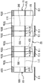
도 2는 본 실시형태의 슬로터 장치를 나타내는 개략 구성도이다.
도 3은 슬로터 장치를 나타내는 사시도이다.
도 4는 슬로터 장치의 변형예를 나타내는 개략 구성도이다.
도 5는 싱글 박스 시트 가공 시에 있어서의 슬로터 나이프의 배열을 나타내는 슬로터 장치의 개략도이다.
도 6은 싱글 박스 시트를 나타내는 평면도이다.
도 7은 트윈 박스 시트 가공 시에 있어서의 슬로터 나이프의 배열을 나타내는 슬로터 장치의 개략도이다.
도 8은 트윈 박스 시트를 나타내는 평면도이다.
도 9는 연통홈을 가공하기 위한 복수의 슬로터 나이프의 위상을 설명하기 위한 개략도이다.
도 10은 다른 연통홈을 가공하기 위한 복수의 슬로터 나이프의 위상을 설명하기 위한 개략도이다.
도 11은 다른 연통홈을 가공하기 위한 복수의 슬로터 나이프의 위상을 설명하기 위한 개략도이다.
도 12는 트리플 박스 시트 가공 시에 있어서의 슬로터 나이프의 배열을 나타내는 개략도이다.
도 13은 트윈 박스 시트의 평면도이다.BRIEF DESCRIPTION OF THE DRAWINGS Fig. 1 is a schematic structural view showing a make-up machine of the present embodiment. Fig.
Fig. 2 is a schematic configuration diagram showing the slitter apparatus of the present embodiment.
3 is a perspective view showing the slitter device.
4 is a schematic configuration diagram showing a modified example of the slitter apparatus.
5 is a schematic view of a slitter apparatus showing the arrangement of the slitter knives at the time of processing a single box sheet.
6 is a plan view showing the single box sheet.
Fig. 7 is a schematic view of a slitter apparatus showing the arrangement of the slitter knives at the time of twin box sheet processing. Fig.
8 is a plan view showing the twin box sheet.
9 is a schematic view for explaining the phases of a plurality of slitter knives for machining the communication grooves.
10 is a schematic view for explaining the phases of a plurality of slitter knives for machining other communication grooves.
11 is a schematic view for explaining the phases of a plurality of slitter knives for machining other communication grooves.
Fig. 12 is a schematic view showing the arrangement of the slitter knives in the processing of the triple box sheet. Fig.
13 is a plan view of the twin box sheet.
이하에 첨부 도면을 참조하여, 본 발명에 관한 슬로터 장치 및 시트의 홈 절삭 가공 방법, 제함기의 적합한 실시형태를 상세하게 설명한다. 또한, 이 실시형태에 의하여 본 발명이 한정되는 것은 아니고, 또 실시형태가 복수 있는 경우에는, 각 실시형태를 조합하여 구성하는 것도 포함하는 것이다.BEST MODE FOR CARRYING OUT THE INVENTION Hereinafter, with reference to the accompanying drawings, a preferred embodiment of a slitting apparatus and a groove cutting method for a slitting apparatus and a sheet former according to the present invention will be described in detail. In addition, the present invention is not limited to the embodiments, and in the case where there are a plurality of embodiments, the present invention also includes a combination of the embodiments.
도 1은 본 실시형태의 제함기를 나타내는 개략 구성도이다.BRIEF DESCRIPTION OF THE DRAWINGS Fig. 1 is a schematic structural view showing a make-up machine of the present embodiment. Fig.
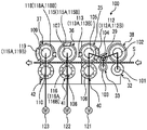
본 실시형태에 있어서, 도 1에 나타내는 바와 같이, 제함기(10)는, 골판지 시트(S)를 가공함으로써 골판지 상자(상자체)(B)를 제조하는 것이다. 이 제함기(10)는, 골판지 시트(S) 및 골판지 상자(B)를 반송하는 방향(D)으로 직선 형상을 이루어 배치된 급지부(11), 인쇄부(21), 배지부(31), 다이컷팅부(51), 절단부(61), 증속부(71), 폴딩부(81), 카운터 이젝터부(91)로 구성되어 있다.In this embodiment, as shown in Fig. 1, the
급지부(11)는, 골판지 시트(S)를 한 장씩 송출하여 일정한 속도로 인쇄부(21)에 보내는 것이다. 이 급지부(11)는, 테이블(12)과, 프론트 가이드(13)와, 공급 롤러(14)와, 흡인 장치(15)와, 피드 롤(16)을 갖고 있다. 테이블(12)은, 다수 매의 골판지 시트(S)를 중첩하여 재치 가능함과 함께, 승강 가능하게 지지되어 있다. 프론트 가이드(13)는, 테이블(12) 상에 중첩된 골판지 시트(S)의 전단부 위치를 위치 결정할 수 있고, 하단부와 테이블(12)의 사이에 1매의 골판지 시트(S)가 통과 가능한 간극이 확보되어 있다. 공급 롤러(14)는, 테이블(12)에 대응하여 골판지 시트(S)의 반송 방향(D)으로 복수 배치되어 이루어지고, 테이블(12)이 하강했을 때에, 중첩된 다수 매의 골판지 시트(S) 중 최하 위치에 있는 골판지 시트(S)를 전방으로 송출할 수 있다. 흡인 장치(15)는, 중첩된 골판지 시트(S)를 하방, 즉 테이블(12)이나 공급 롤러(14)측에 흡인하는 것이다. 피드 롤(16)은, 공급 롤러(14)에 의하여 송출된 골판지 시트(S)를 인쇄부(21)에 공급할 수 있다.The
인쇄부(21)는, 골판지 시트(S)의 표면에 다색쇄(본 실시형태에서는, 4색쇄)를 행하는 것이다. 이 인쇄부(21)는, 4개의 인쇄 유닛(21A, 21B, 21C, 21D)이 직렬을 이루어 배치되고, 골판지 시트(S)의 표면에 4개의 잉크색을 사용하여 인쇄를 행할 수 있다. 각 인쇄 유닛(21A, 21B, 21C, 21D)은, 거의 동일하게 구성되고, 인쇄 실린더(22), 잉크 공급 롤(애니록스 롤)(23), 잉크 챔버(24), 지지 롤(25)을 갖고 있다. 인쇄 실린더(22)는, 그 외주부에 인판(26)이 장착되어, 회전 가능하게 마련되어 있다. 잉크 공급 롤(23)은, 인쇄 실린더(22)의 근방에서 인판(26)에 대접(對接)하도록 배치되어, 회전 가능하게 마련되어 있다. 잉크 챔버(24)는, 잉크를 축적하는 것이며, 잉크 공급 롤(23)의 근방에 마련되어 있다. 지지 롤(25)은, 인쇄 실린더(22)와의 사이에서 골판지 시트(S)를 협지함으로써, 소정의 인압을 부여하면서 반송하는 것이며, 인쇄 실린더(22)의 하방으로 대향하여 회전 가능하게 마련되어 있다. 또한, 도시하지 않지만, 각 인쇄 유닛(21A, 21B, 21C, 21D)은, 그 전후에 상하 한 쌍의 이송 롤이 마련되어 있다.The
배지부(31)는, 슬로터 장치(100)(도 2 참조)를 갖고, 골판지 시트(S)에 대하여, 괘선 가공과 절단 가공과 홈 절삭 가공과 접착 여유편 가공을 실시하는 것이다. 이 배지부(31)는, 제1 괘선 롤(32)과, 제2 괘선 롤(33)과, 슬리터 헤드(34) 및 제1 슬로터 헤드(35)와, 제2 슬로터 헤드(36)와, 제3 슬로터 헤드(37)를 갖고 있다.The
제1 괘선 롤(32)은, 원 형상으로 형성되고, 골판지 시트(S)의 반송 방향(D)에 직교하는 수평 방향으로 소정 간격으로 복수(본 실시형태에서는, 4개) 배치되어 있다. 제2 괘선 롤(33)은, 원 형상으로 형성되고, 골판지 시트(S)의 반송 방향(D)에 직교하는 수평 방향으로 소정 간격으로 복수(본 실시형태에서는, 4개) 배치되어 있다. 하측에 배치된 제1 괘선 롤(32)은, 골판지 시트(S)의 이면(하면)에 괘선 가공을 실시하는 것이며, 하측에 배치된 제2 괘선 롤(33)은, 제1 괘선 롤(32)과 마찬가지로, 골판지 시트(S)의 이면(하면)에 괘선 가공을 실시하는 것이다. 각 괘선 롤(32, 33)은, 대향하는 상방 위치에 지지 롤(39, 39)이 동기하여 회전 가능하게 마련되어 있다.The first ruled-line rolls 32 are formed in a circular shape and are arranged in plural (four in this embodiment) at predetermined intervals in the horizontal direction perpendicular to the conveying direction D of the corrugated cardboard sheet S. The second ruled line rolls 33 are formed in a circular shape and are arranged in plural (four in the present embodiment) at predetermined intervals in the horizontal direction orthogonal to the conveying direction D of the corrugated cardboard sheet S. The first ruled-
제1 슬로터 헤드(35)는, 원 형상으로 형성되고, 골판지 시트(S)의 반송 방향(D)에 직교하는 수평 방향으로 소정 간격으로 복수(본 실시형태에서는, 4개) 배치되어 있다. 각 제1 슬로터 헤드(35)는, 반송되는 골판지 시트(S)에 있어서의 폭 방향의 소정의 위치에 대응하여 마련되어 있고, 이 골판지 시트(S)에 있어서의 소정의 위치에서 홈 절삭 가공을 행함과 함께, 접착 여유편 가공을 행할 수 있다. 제2 슬로터 헤드(36)는, 원 형상으로 형성되고, 골판지 시트(S)의 반송 방향(D)에 직교하는 수평 방향으로 소정 간격으로 복수(본 실시형태에서는, 4개) 배치되어 있다. 각 제2 슬로터 헤드(36)는, 반송되는 골판지 시트(S)에 있어서의 폭 방향의 소정의 위치에 대응하여 마련되어 있고, 이 골판지 시트(S)에 있어서의 소정의 위치에서 홈 절삭 가공을 행함과 함께, 접착 여유편 가공을 행할 수 있다.The first slotter
슬리터 헤드(34) 및 제3 슬로터 헤드(37)는, 각각 원 형상으로 형성되고, 골판지 시트(S)의 반송 방향(D)에 직교하는 수평 방향으로 소정 간격으로 복수(본 실시형태에서는, 5개) 배치되어 있다. 슬리터 헤드(34)는, 1개로 구성되고, 반송되는 골판지 시트(S)에 있어서의 폭 방향의 단부에 대응하여 마련되어 있으며, 이 골판지 시트(S)에 있어서의 폭 방향의 단부를 절단할 수 있다. 각 제3 슬로터 헤드(37)는, 4개로 구성되고, 반송되는 골판지 시트(S)에 있어서의 폭 방향의 소정의 위치에 대응하여 마련되어 있으며, 이 골판지 시트(S)에 있어서의 소정의 위치에서 홈 절삭 가공을 행함과 함께, 접착 여유편 가공을 행할 수 있다. 제1 슬로터 헤드(35)는, 대향하는 하방 위치에 하측 블레이드(40)가 동기하여 회전 가능하게 마련되고, 제2 슬로터 헤드(36)는, 대향하는 하방 위치에 하측 블레이드(41)가 동기하여 회전 가능하게 마련되며, 슬리터 헤드(34) 및 제3 슬로터 헤드(37)는, 대향하는 하방 위치에 하측 블레이드(42)가 동기하여 회전 가능하게 마련되어 있다.The
다이컷팅부(51)는, 골판지 시트(S)에 대하여, 손잡이용 천공 가공을 실시하는 것이다. 이 다이컷팅부(51)는, 상하 한 쌍의 이송 부재(52)와, 앤빌 실린더(53) 및 나이프 실린더(54)를 갖고 있다. 이송 부재(52)는, 골판지 시트(S)를 상하로부터 협지하여 반송하는 것이며, 회전 가능하게 마련되어 있다. 앤빌 실린더(53) 및 나이프 실린더(54)는, 각각 원 형상으로 형성되고, 도시하지 않은 구동 장치에 의하여 동기하여 회전 가능하게 되어 있다. 앤빌 실린더(53)는, 외주부에 앤빌이 형성되는 한편, 나이프 실린더(54)는, 외주부에 있어서의 소정의 위치에 헤드 및 다이가 형성되어 있다.The
절단부(61)는, 골판지 시트(S)를 반송 방향(D)의 중간 위치에서 2매로 절단하는 것이다. 절단부(61)는, 상하 한 쌍의 이송 부재(62)와, 상하 한 쌍의 절단 롤(63, 64)을 갖고 있다. 이송 부재(62)는, 골판지 시트(S)를 상하로부터 협지하여 반송하는 것이며, 회전 가능하게 마련되어 있다. 절단 롤(63, 64)은, 각각 원 형상으로 형성되고, 도시하지 않은 구동 장치에 의하여 동기하여 회전 가능하게 되어 있다. 절단 롤(63, 64)은, 외주부의 소정의 위치에 절단 블레이드가 고정되어 있다.The
증속부(71)는, 절단된 골판지 시트(S)를 증속함으로써, 반송되는 각 골판지 시트(S)의 사이에 소정의 반송 간격을 확보하는 것이다. 증속부(71)는, 상하 한 쌍의 반송 벨트(72, 73)를 갖고 있다. 반송 벨트(72, 73)는, 골판지 시트(S)를 상하로부터 협지하여 반송하는 것이며, 도시하지 않은 구동 장치에 의하여 동기하여 회전 가능하게 되어 있다. 증속부(71)에 있어서의 골판지 시트(S)의 반송 속도는, 절단부(61)까지의 골판지 시트(S)의 반송 속도보다 빠른 속도로 설정되어 있다.The
폴딩부(81)는, 골판지 시트(S)를 반송 방향(D)으로 이동시키면서 접지하고, 폭 방향의 양 단부를 접합하여 편평 형상의 골판지 상자(B)를 형성하는 것이다. 이 폴딩부(81)는, 상측 반송 벨트(82)와, 하측 반송 벨트(83, 84)와, 성형 장치(85)를 갖고 있다. 상측 반송 벨트(82) 및 하측 반송 벨트(83, 84)는, 골판지 시트(S) 및 골판지 상자(B)를 상하로부터 협지하여 반송하는 것이다. 성형 장치(85)는, 좌우 한 쌍의 성형 벨트를 갖고, 이 성형 벨트에 의하여 골판지 시트(S)에 있어서의 폭 방향의 각 단부를 하방으로 접어 구부리면서 접지하는 것이다. 또, 폴딩부(81)는, 접착 장치(86)가 마련되어 있다. 이 접착 장치(86)는, 글루 건을 갖고, 소정의 타이밍에 풀을 토출시킴으로써, 골판지 시트(S)에 있어서의 소정의 위치에 접착을 행할 수 있다.The folding
카운터 이젝터부(91)는, 골판지 상자(B)를 계수하면서 중첩한 후, 소정 수의 배치(batch)로 구분한 후, 배출하는 것이다. 이 카운터 이젝터부(91)는, 호퍼 장치(92)를 갖고 있다. 이 호퍼 장치(92)는, 골판지 상자(B)가 중첩되는 승강 가능한 엘리베이터(93)를 갖고, 이 엘리베이터(93)에는, 프론트 스토퍼와 앵글 어렌지먼트 플레이트가 마련되어 있다. 또한, 호퍼 장치(92)의 하방에, 반출 컨베이어(94)가 마련되어 있다.The
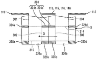
여기에서, 상술한 본 실시형태의 제함기에서, 골판지 시트(S)로부터 골판지 상자(B)를 제조하는 동작을 설명한다. 본 실시형태의 제함기는, 2매의 골판지 시트(S)(S1, S2)가 연결된 상태에서 인쇄, 괘선 가공, 홈 및 접착 여유편의 가공, 천공 가공을 행한 후, 2매의 골판지 시트(S1, S2)로 절단하고, 각 골판지 시트(S1, S2)를 접지하여 골판지 상자(B)를 제조하는 것이다. 도 13은 트윈 박스 시트의 평면도이다.Here, the operation of manufacturing the corrugated cardboard box B from the corrugated cardboard sheet S in the above-described embodiment of the present invention will be described. The first and second corrugated cardboard sheets S 1 and S 2 are connected to each other. The two cardboard sheets S 1 and S 2 are connected to each other, and the corrugated cardboard sheets S 1 and S 2 are subjected to printing, ruling, S2, and each corrugated cardboard sheet S1, S2 is grounded to manufacture the corrugated cardboard box B. 13 is a plan view of the twin box sheet.
골판지 시트(트윈 박스 시트)(S)는, 표측 라이너와 이측 라이너의 사이에 파형을 이루는 골심지가 접착되어 형성된 것이다. 이 골판지 시트(S)는, 도 13에 나타내는 바와 같이, 제함기(10)의 전공정에서, 4개의 접는 선(301, 302, 303, 304)이 형성되어 있다. 이 접는 선(301, 302, 303, 304)은, 제함기(10)에서 제조된 골판지 상자(B)를, 나중에 조립할 때에 플랩을 접기 위한 것이다. 이와 같은 골판지 시트(S)는, 도 1에 나타내는 바와 같이, 급지부(11)의 테이블(12) 상에 중첩된다.The corrugated cardboard sheet (twin box sheet) S is formed by adhering corrugated paper forming a waveform between the front side liner and the side liner. This corrugated cardboard sheet S is formed with four
급지부(11)에서, 테이블(12) 상에 중첩되어 있는 다수 매의 골판지 시트(S)는, 먼저, 프론트 가이드(13)에 의하여 위치 결정되고, 다음으로, 테이블(12)이 하강함으로써, 복수의 공급 롤러(14)에 의하여 최하 위치에 있는 골판지 시트(S)가 송출된다. 따라서, 이 골판지 시트(S)는, 한 쌍의 피드 롤(16)에 의하여 소정의 일정측에서, 인쇄부(21)에 공급된다.A plurality of corrugated cardboard sheets S superimposed on the table 12 are first positioned by the
인쇄부(21)에서, 각 인쇄 유닛(21A, 21B, 21C, 21D)에서는, 잉크 공급 롤(23)의 표면에 잉크 챔버(24)로부터 잉크가 공급되고 있고, 인쇄 실린더(22) 및 잉크 공급 롤(23)이 회전하면, 잉크 공급 롤(23)의 표면의 잉크가 인판(26)에 전이된다. 그리고, 인쇄 실린더(22)와 지지 롤(25)의 사이에 골판지 시트(S)가 반송되면, 이 골판지 시트(S)가 인판(26)과 지지 롤(25)에 의하여 협지되고, 이 골판지 시트(S)에 인압이 부여됨으로써 그 표면에 인쇄가 실시된다. 인쇄된 골판지 시트(S)는, 이송 롤에 의하여 배지부(31)에 반송된다.In the
배지부(31)에서, 먼저, 골판지 시트(S)가 제1 괘선 롤(32)을 통과할 때, 도 13에 나타내는 바와 같이, 골판지 시트(S)의 이면(이측 라이너)측에 괘선(312, 313, 314, 315)이 형성된다. 또, 골판지 시트(S)가 제2 괘선 롤(33)을 통과할 때, 제1 괘선 롤(32)과 마찬가지로, 골판지 시트(S)의 이면(이측 라이너)측에 괘선(312, 313, 314, 315)이 재형성된다.13, a ruled
다음으로, 이 괘선(312, 313, 314, 315)이 형성된 골판지 시트(S)가 슬리터 헤드(34)를 통과할 때, 절단 위치(311)의 위치에서 단부(321a, 321b)가 절단된다. 또, 골판지 시트(S)가 제1, 제2, 제3 슬로터 헤드(35, 36, 37)를 통과할 때, 괘선(312, 313, 314)의 위치에 홈(322a, 322b, 322c, 322d, 323a, 323b, 323c, 323d, 324a, 324b, 324c, 324d)이 형성된다. 이때, 괘선(315)의 위치에서 단부(325a, 325b, 325c, 325d)가 절단됨으로써, 접착 여유편(326a, 326b)이 형성된다.Next, when the corrugated board sheet S on which the ruled
또한, 후술하지만, 골판지 시트(S)가 제1 슬로터 헤드(35)를 통과할 때, 홈(322d, 323d, 324d)이 형성되고, 골판지 시트(S)가 제3 슬로터 헤드(37)를 통과할 때, 홈(322a, 323a, 324a)이 형성되며, 골판지 시트(S)가 제1, 제2, 제3 슬로터 헤드(35, 36, 37)를 통과할 때, 홈(322b, 322c, 323b, 323c, 324b, 324c)이 단계적으로 형성된다. 여기에서, 홈(322b, 322c, 323b, 323c, 324b, 324c)은, 연통홈(322, 323, 324)이며, 홈(322a, 322d, 323a, 323d, 324a, 324d)은 개방홈이다. 그 후, 골판지 시트(S)는, 도 1에 나타내는 바와 같이 다이컷팅부(51)에 반송된다.As will be described later,
다이컷팅부(51)에서, 골판지 시트(S)는, 앤빌 실린더(53)와 나이프 실린더(54)의 사이를 통과할 때, 손잡이 구멍(도시 생략)이 형성된다. 단, 손잡이 구멍 가공은, 골판지 시트(S)의 종류에 따라 적절히 행해지는 것이며, 손잡이 구멍이 불필요할 때, 이 손잡이 구멍 가공을 실시하기 위한 블레이드 장착대(펀칭 블레이드)가 나이프 실린더(54)로부터 분리되어 있고, 골판지 시트(S)는, 회전하는 앤빌 실린더(53)와 나이프 실린더(54)의 사이를 통과한다. 그리고, 손잡이 구멍이 형성된 골판지 시트(S)는 절단부(61)에 반송된다.In the
절단부(61)에서, 골판지 시트(S)는, 상하의 절단 롤(63, 64)의 사이를 통과할 때, 도 13에 나타내는 바와 같이, 절단 위치(331)에서 절단된다. 이로 인하여, 골판지 시트(S)는, 홈(322a, 322b, 323a, 323b, 324a, 324b)과 접착 여유편(326a)이 형성된 골판지 시트(S1)와, 홈(322c, 322d, 323c, 323d, 324c, 324d)과 접착 여유편(326b)이 형성된 골판지 시트(S2)로 절단된다. 그리고, 각 골판지 시트(S1, S2)는, 도 1에 나타내는 바와 같이, 순서대로 증속부(71)에 반송된다.In the
증속부(71)에서, 절단된 골판지 시트(S1, S2)는, 상하의 반송 벨트(72, 73)에 의하여 협지되면서 반송된다. 이때, 골판지 시트(S1, S2)는, 절단부(61)의 반송 속도로부터 증속된 반송 속도로 반송됨으로써, 각 골판지 시트(S1, S2)의 사이에 소정의 반송 간격이 형성된다. 그 후, 골판지 시트(S)는 폴딩부(81)에 반송된다.In the
폴딩부(81)에서, 골판지 시트(S1(S2))는, 상측 반송 벨트(82) 및 하측 반송 벨트(83, 84)에 의하여 반송 방향(D)으로 이동되면서, 접착 장치(86)에 의하여 접착 여유편(326a(326b))에 풀이 도포된 후, 성형 장치(85)에 의하여 괘선(312, 314)을 기준점으로 하여 하방으로 접지된다. 이 접지가 180도 근처까지 진행되면 접지력이 강해져, 접착 여유편(326a(326b))과 골판지 시트(S1(S2))의 단부가 압압되어 서로 밀착되고, 골판지 시트(S1(S2))의 양 단부가 접합되어, 골판지 상자(B)가 된다. 그리고, 이 골판지 상자(B)는, 도 1에 나타내는 바와 같이, 카운터 이젝터부(91)에 반송된다.In the
카운터 이젝터부(91)에서, 골판지 상자(B)는, 호퍼 장치(92)에 보내지고, 반송 방향(D)의 선단부가 프론트 스토퍼에 닿아, 앵글 어렌지먼트 플레이트에 의하여 정형된 상태에서 엘리베이터(93) 상에 중첩된다. 그리고, 소정 수의 골판지 상자(B)가 엘리베이터(93) 상에 중첩되면, 이 엘리베이터(93)가 하강하고, 소정 수의 골판지 상자(B)가 1배치(batch)가 되고 반출 컨베이어(94)에 의하여 배출되며, 제함기(10)의 후공정으로 보내진다.In the
여기에서, 본 실시형태의 슬로터 장치를 갖는 배지부(31)에 대하여 상세하게 설명한다. 도 2는 본 실시형태의 슬로터 장치를 나타내는 개략 구성도, 도 3은 슬로터 장치를 나타내는 사시도이다.Here, the
배지부(31)는, 도 2 및 도 3에 나타내는 바와 같이, 슬로터 장치(100)를 갖고 있다. 슬로터 장치(100)는, 골판지 시트(S)에 대하여, 괘선 가공과 절단 가공과 홈 절삭 가공과 접착 여유편 가공을 실시하는 것이다. 이 슬로터 장치(100)는, 제1 괘선 롤(32)과 지지 롤(38), 제2 괘선 롤(33)과 지지 롤(39), 제1 슬로터 헤드(제1 상측 슬로터 헤드)(35)와 제1 하측 블레이드(제1 하측 슬로터 헤드)(40), 제2 슬로터 헤드(제2 상측 슬로터 헤드)(36)와 제2 하측 블레이드(제2 하측 슬로터 헤드)(41), 슬리터 헤드(34) 및 제3 슬로터 헤드(제3 상측 슬로터 헤드)(37)와 제3 하측 블레이드(제3 하측 슬로터 헤드)(42)로 구성되어 있다.As shown in Fig. 2 and Fig. 3, the
상하의 롤축(101, 102)은, 각 단부가 도시하지 않은 프레임에 회전 가능하게 지지되어 있고, 하측 롤축(101)에 4개의 제1 괘선 롤(32)이 축 방향으로 소정 간격을 두고 고정되고, 상측 롤축(102)에 4개의 지지 롤(38)이 축 방향으로 소정 간격을 두고 고정되어 있다. 또, 상하의 롤축(103, 104)은, 각 단부가 도시하지 않은 프레임에 회전 가능하게 지지되어 있고, 하측 롤축(103)에 4개의 제2 괘선 롤(33)이 축 방향으로 소정 간격을 두고 고정되며, 상측 롤축(104)에 4개의 지지 롤(39)이 그 축 방향으로 소정 간격을 두고 고정되어 있다.Each of the upper and
이 경우, 각 제1 괘선 롤(32)과 각 지지 롤(38), 각 제2 괘선 롤(33)과 각 지지 롤(39)은, 상하로 대향하여 배치되어 있다. 또, 각 제1 괘선 롤(32)은, 그 하류측에 각 제2 괘선 롤(33)이 수평 방향으로 소정 간극을 두고 배치되어 있다. 그리고, 제1 괘선 롤(32)과 제2 괘선 롤(33)은, 롤축(101, 103)의 축 방향에 있어서의 동일 위치에 배치되어 있고, 제1 괘선 롤(32)의 직경에 대하여 제2 괘선 롤(33)의 직경이 작게 설정되어 있다.In this case, each of the first ruled-line rolls 32, the respective supporting rolls 38, the second ruled-line rolls 33, and the respective supporting rolls 39 are vertically opposed to each other. Each of the first ruled-line rolls 32 is arranged on the downstream side thereof with the second ruled-line rolls 33 arranged with a predetermined gap in the horizontal direction. The first ruled-
따라서, 제1 괘선 롤(32)과 지지 롤(38)은 상하로 대향하여 배치되어, 골판지 시트(S)가 이 제1 괘선 롤(32)과 지지 롤(38)의 사이에 진입하면, 제1 괘선 롤(32)의 외주부와 지지 롤(38)의 외주부가 골판지 시트(S)를 협지하고, 이 골판지 시트(S)가 양자의 사이를 통과할 때에 하면에 괘선이 형성된다. 또, 제2 괘선 롤(33)과 지지 롤(39)은 상하로 대향하여 배치되어, 골판지 시트(S)가 이 제2 괘선 롤(33)과 지지 롤(39)의 사이에 진입하면, 제2 괘선 롤(33)의 외주부와 지지 롤(39)의 외주부가 골판지 시트(S)를 협지하고, 이 골판지 시트(S)가 양자의 사이를 통과할 때에 하면에 괘선이 재형성된다. 이 경우, 골판지 시트(S)는, 동일 위치에 제1 괘선 롤(32)과 제2 괘선 롤(33)이 전동함으로써, 하나의 괘선이 형성된다.Therefore, when the corrugated board sheet S enters between the first ruled-
또, 상하의 슬로터축(회전축)(105, 106)은, 각 단부가 도시하지 않은 프레임에 회전 가능하게 지지되어 있으며, 상측 슬로터축(105)에 4개의 제1 슬로터 헤드(35(35A, 35B))와 1개의 이송 롤러(43)가 축 방향으로 소정 간격을 두고 고정되고, 하측 슬로터축(106)에 4개의 제1 하측 블레이드(40)와 1개의 이송 롤러(44)가 축 방향으로 소정 간격을 두고 고정되어 있다. 이 경우, 4개의 제1 슬로터 헤드(35)에 대응하여 4개의 제1 하측 블레이드(40)가 상하에 배치되고, 이송 롤러(43, 44)가 상하에 배치되어 있다. 또, 상하의 슬로터축(107, 108)은, 각 단부가 도시하지 않은 프레임에 회전 가능하게 지지되어 있으며, 상측 슬로터축(107)에 4개의 제2 슬로터 헤드(36(36A, 36B))와 1개의 이송 롤러(45)가 축 방향으로 소정 간격을 두고 고정되고, 하측 슬로터축(108)에 4개의 제2 하측 블레이드(41)와 1개의 이송 롤러(46)가 그 축 방향으로 소정 간격을 두고 고정되어 있다. 또한, 상하의 슬로터축(109, 110)은, 각 단부가 도시하지 않은 프레임에 회전 가능하게 지지되어 있으며, 상측 슬로터축(109)에 1개의 슬리터 헤드(34)와 4개의 제3 슬로터 헤드(37)(37A, 37B)가 축 방향으로 소정 간격을 두고 고정되고, 하측 슬로터축(110)에 5개의 제3 하측 블레이드(42)가 그 축 방향으로 소정 간격을 두고 고정되어 있다.Each of the upper and lower slatting shafts (rotation shafts) 105 and 106 is rotatably supported on a frame (not shown) at each end. Four first slatter heads 35 (35A and 35B) And four
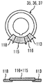
그리고, 3개의 제1 슬로터 헤드(35A)는, 각각 외주부에 제1 슬로터 나이프(112(112A))와 제2 슬로터 나이프(113(113A))가 장착되고, 1개의 제1 슬로터 헤드(35B)는, 외주부에 제1 슬로터 나이프(112(112B))와 제2 슬로터 나이프(113(113B))가 장착되어 있다. 또, 3개의 제2 슬로터 헤드(36A)는, 각각 외주부에 제3 슬로터 나이프(115(115A))와 제4 슬로터 나이프(116(116A))가 장착되고, 1개의 제2 슬로터 헤드(36B)는, 외주부에 제3 슬로터 나이프(115(115B))와 제4 슬로터 나이프(116(116B))가 장착되어 있다. 또한, 1개의 슬리터 헤드(34)는, 외주부에 슬리터 나이프(111)가 장착되고, 3개의 제3 슬로터 헤드(37A)는, 각각 외주부에 제5 슬로터 나이프(118(118A))와 제6 슬로터 나이프(119(119A))가 장착되며, 1개의 제3 슬로터 헤드(37B)는, 외주부에 제5 슬로터 나이프(118(118B))와 제6 슬로터 나이프(119(119B))가 장착되어 있다.The first three
슬리터 헤드(34)는, 골판지 시트(S)의 폭 방향의 일단부를 절단하는 단부 절단용으로서 사용되는 것이며, 도 13에서, 슬리터 나이프(111)가 절단 위치(311)에서 단부(321a, 321b)를 절단할 수 있다. 도 2 및 도 3으로 되돌아가, 이 슬리터 헤드(34)는, 전체 둘레에 슬리터 나이프(111)가 마련되어 있다.The
3개의 제1 슬로터 헤드(35A)와 3개의 제2 슬로터 헤드(36A)와 3개의 제3 슬로터 헤드(37A)는, 골판지 시트(S)에 반송 방향(D)을 따라 홈을 형성하는 홈 절삭 가공용으로서 사용되는 것이며, 도 13에서, 홈(322a, 322b, 322c, 322d, 323a, 323b, 323c, 323d, 324a, 324b, 324c, 324d)을 형성할 수 있다. 도 2 및 도 3으로 되돌아가, 제1 슬로터 헤드(35A)는, 원주 방향의 일부에 제1 슬로터 나이프(112A)와 제2 슬로터 나이프(113A)가 원주 방향으로 나란히 마련되어 있다. 제2 슬로터 헤드(36A)는, 원주 방향의 일부에 제3 슬로터 나이프(115A)와 제4 슬로터 나이프(116A)가 원주 방향으로 나란히 마련되어 있다. 제3 슬로터 헤드(37A)는, 원주 방향의 일부에 제5 슬로터 나이프(118A)와 제6 슬로터 나이프(119A)가 원주 방향으로 나란히 마련되어 있다.The three first
1개의 제1 슬로터 헤드(35B)와 1개의 제2 슬로터 헤드(36B)와 1개의 제3 슬로터 헤드(37B)는, 슬로터축(105, 107, 109)의 단부에 배치되어 있고, 골판지 시트(S)의 폭 방향의 타단부를 절단하여 접착 여유편을 형성하는 접착 여유편 가공용으로서 사용되는 것이며, 도 13에서, 단부(325a, 325b, 325c, 325d)를 절단하여 접착 여유편(326a, 326b)을 형성할 수 있다. 도 2 및 도 3으로 되돌아가, 제1 슬로터 헤드(35B)는, 원주 방향의 일부에 제1 슬로터 나이프(112B)와 제2 슬로터 나이프(113B)가 원주 방향으로 나란히 마련되어 있다. 제2 슬로터 헤드(36B)는, 원주 방향의 일부에 제3 슬로터 나이프(115B)와 제4 슬로터 나이프(116B)가 원주 방향으로 나란히 마련되어 있다. 제3 슬로터 헤드(37B)는, 원주 방향의 일부에 제5 슬로터 나이프(118B)와 제6 슬로터 나이프(119B)가 원주 방향으로 나란히 마련되어 있다.One
이 슬로터 나이프(112B, 113B, 115B, 116B, 118B, 119B)는, 도시하지 않지만, 대략 직교하는 방향으로 배치되는 제1 절삭 블레이드와 제2 절삭 블레이드로 구성되어 있다. 제1 절삭 블레이드는, 골판지 시트(S)의 반송 방향을 따라 각 슬로터 헤드(35B, 36B, 37B)에 장착되고, 제2 절삭 블레이드는, 골판지 시트(S)의 반송 방향에 교차하는 폭 방향을 따라 각 슬로터 헤드(35B, 36B, 37B)에 장착되어 있다. 이로 인하여, 제1 절삭 블레이드와 제2 절삭 블레이드는, L자 형상을 이루어 배치되게 되어, 골판지 시트(S)의 폭 방향의 타단부를 L자로 절단함으로써, 도 13에 있어서의 단부(325a, 325b, 325c, 325d)를 절단할 수 있다.The
이 경우, 각 제1 슬로터 헤드(35(35A, 35B))와 각 제1 하측 블레이드(40)는, 각각 상하로 대향하여 배치되고, 각 제2 슬로터 헤드(36(36A, 36B))와 각 제2 하측 블레이드(41)는, 각각 상하로 대향하여 배치되며, 슬리터 헤드(34) 및 각 제3 슬로터 헤드(37(37A, 37))와 각 제3 하측 블레이드(42)는, 각각 상하로 대향하여 배치되어 있다. 또, 각 제1 슬로터 헤드(35(35A, 35B))는, 각 제2 괘선 롤(33)의 하류측에 수평 방향으로 소정 간극을 두고 배치되고, 각 제1 슬로터 헤드(35(35A, 35B))는, 그 하류측에 각 제2 슬로터 헤드(36(36A, 36B))가 수평 방향으로 소정 간극을 두고 배치되며, 각 제2 슬로터 헤드(36(36A, 36B))는, 그 하류측에 슬리터 헤드(34) 및 각 제3 슬로터 헤드(37(37A, 37))가 수평 방향으로 소정 간극을 두고 배치되어 있다. 그리고, 각 제2 괘선 롤(33)과 각 제1 슬로터 헤드(35(35A, 35B))는, 각 축(103, 105)의 축 방향에 있어서의 동일 위치에 배치되어 있고, 각 제1 슬로터 헤드(35(35A, 35B))와 각 제2 슬로터 헤드(36(36A, 36B))는, 슬로터축(105, 107)의 축 방향에 있어서의 동일 위치에 배치되어 있으며, 각 제2 슬로터 헤드(36(36A, 36B))와 각 제3 슬로터 헤드(37(37A, 37))는, 슬로터축(107, 109)의 축 방향에 있어서의 동일 위치에 배치되어 있다.In this case, each of the first slatter heads 35 (35A, 35B) and each of the first
그리고, 롤축(101, 102, 103, 104) 및 슬로터축(105, 106)은, 제1 구동 장치(121)가 구동 연결되고, 이 제1 구동 장치(121)에 의하여 괘선 롤(32, 33)과 지지 롤(38, 39)과 제1 슬로터 헤드(35)와 하측 블레이드(40)를 동기하여 구동 회전시킬 수 있다. 이 경우, 제1 구동 장치(121)와 각 롤축(101, 102, 103, 104) 및 슬로터축(105, 106)은, 도시하지 않은 기어에 의하여 구동 연결되어 있다. 슬로터축(107, 108)은, 제2 구동 장치(122)가 구동 연결되고, 이 제2 구동 장치(122)에 의하여 제2 슬로터 헤드(36) 및 하측 블레이드(41)를 구동 회전시킬 수 있다. 슬로터축(109, 110)은, 제3 구동 장치(123)가 구동 연결되고, 이 제3 구동 장치(123)에 의하여 제3 슬로터 헤드(37) 및 하측 블레이드(42)를 구동 회전시킬 수 있다.The
각 구동 장치(121, 122, 123)는, 도시하지 않은 모터 드라이버가 접속되고, 이 모터 드라이버는, 제어 장치에 접속되어 있다. 또, 제함기(10)는, 급지부(11)에 골판지 시트(S)의 위치를 검출하는 위치 센서가 마련되어 있고, 제어 장치는, 위치 센서의 검출 결과에 근거하여 각 구동 장치(121, 122, 123)를 제어한다.A motor driver (not shown) is connected to each of the driving
또한, 상술한 설명에서, 슬로터 장치(100)는, 제1 괘선 롤(32)과 지지 롤(38), 제2 괘선 롤(33)과 지지 롤(39), 슬리터 헤드(34) 및 제1 슬로터 헤드(35)와 제1 하측 블레이드(40), 제2 슬로터 헤드(36)와 제2 하측 블레이드(41), 제3 슬로터 헤드(37)와 제3 하측 블레이드(42)로 구성되어 있지만, 이 구성에 한정되는 것은 아니다.In the above description, the
도 4는 슬로터 장치의 변형예를 나타내는 개략 구성도이다. 도 4에 나타내는 바와 같이, 슬로터 장치(100A)는, 제1 괘선 롤(32)과 지지 롤(38), 제2 괘선 롤(33)과 지지 롤(39), 제1 슬로터 헤드(35)와 제1 하측 블레이드(40), 상하 한 쌍의 제1 이송 부재(반송 장치)(131), 제2 슬로터 헤드(36)와 제2 하측 블레이드(41), 상하 한 쌍의 제2 이송 부재(반송 장치)(132), 슬리터 헤드(34) 및 제3 슬로터 헤드(37)와 제3 하측 블레이드(42)로 구성되어 있다.4 is a schematic configuration diagram showing a modified example of the slitter apparatus. 4, the
여기에서, 각 슬로터 헤드(35, 36, 37)에 장착된 각 슬로터 나이프(112, 113, 115, 116, 118, 119)에 대하여 상세하게 설명한다.Here, each of the
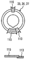
도 2에 나타내는 바와 같이, 각 슬로터 나이프(112, 113, 115, 116, 118, 119)는, 각 슬로터 헤드(35, 36, 37)의 외주부에 장착되어 있고, 외부 블레이드가 원호 형상을 이루고 있다. 그리고, 도 2 및 도 13에 나타내는 바와 같이, 제1 슬로터 헤드(35)가 회전할 때, 제1 슬로터 나이프(112)는, 골판지 시트(S)에 있어서의 반송 방향(D)의 상류측의 단부에 개방홈으로서 홈(322d, 323d, 324d)을 형성하고, 단부(325d)를 절단한다. 또, 제3 슬로터 헤드(37)가 회전할 때, 제6 슬로터 나이프(119)는, 골판지 시트(S)에 있어서의 반송 방향(D)의 하류측의 단부에 개방홈으로서 홈(322a, 323a, 324a)을 형성하고, 단부(325a)를 절단한다. 그리고, 제1, 제2, 제3 슬로터 헤드(35, 36, 37)가 회전할 때, 제2 슬로터 나이프(113)와 제3 슬로터 나이프(115)와 제4 슬로터 나이프(116)와 제5 슬로터 나이프(118) 중 적어도 어느 2개의 슬로터 나이프는, 골판지 시트(S)에 있어서의 반송 방향(D)의 중간부에 연통홈(322, 323, 324(홈(322b, 322c, 323b, 323c, 324b, 324c)))을 형성하고, 단부(325b, 325c)를 절단한다.2, each of the
이로 인하여, 도 2에 나타내는 바와 같이, 제1 슬로터 헤드(35)에서, 제1 슬로터 나이프(112)의 원주 방향 길이는, 제2 슬로터 나이프(113)의 원주 방향 길이보다 길게 설정되어 있다. 제3 슬로터 헤드(37)에서, 제6 슬로터 나이프(119)의 원주 방향 길이는, 제5 슬로터 나이프(118)의 원주 방향 길이보다 길게 설정되어 있다. 여기에서, 제1 슬로터 나이프(112)의 원주 방향 길이와 제6 슬로터 나이프(119)의 원주 방향 길이는, 동일한 길이로 설정되고, 제2 슬로터 나이프(113)의 원주 방향 길이와 제5 슬로터 나이프(118)의 원주 방향 길이는, 동일한 길이로 설정되어 있다.2, the circumferential length of the
또, 제2 슬로터 헤드(36)에서, 제3 슬로터 나이프(115)의 원주 방향 길이는, 제4 슬로터 나이프(116)의 원주 방향 길이보다 길게 설정되어 있다. 그리고, 제2 슬로터 나이프(113)와 제5 슬로터 나이프(118)의 원주 방향 길이는, 제3 슬로터 나이프(115)의 원주 방향 길이보다 짧게 설정되고, 또한 제4 슬로터 나이프(116)의 원주 방향 길이보다 길게 설정되어 있다.In the second slotting
그리고, 제2 슬로터 나이프(113)는, 제1 슬로터 헤드(35)의 외주부에 고정되고, 제3 슬로터 나이프(115)는, 제2 슬로터 헤드(36)의 외주부에 고정되며, 제6 슬로터 나이프(119)는, 제3 슬로터 헤드(37)의 외주부에 고정되어 있다. 한편, 제1 슬로터 나이프(112)는, 제1 슬로터 헤드(35)의 외주부에 원주 방향을 따라 위치 조정 가능하게 장착되고, 제4 슬로터 나이프(116)는, 제2 슬로터 헤드(36)의 외주부에 원주 방향을 따라 위치 조정 가능하게 장착되며, 제5 슬로터 나이프(118)는, 제3 슬로터 헤드(37)의 외주부에 원주 방향을 따라 위치 조정 가능하게 장착되어 있다. 여기에서, 고정이란, 볼트 체결이나 용접 등에 의하여 고정하는 것이며, 위치 조정 가능이란, 레일이나 긴 구멍에 의하여 원주 방향으로 이동 가능하게 하는 것이다.The
이하, 본 실시형태의 슬로터 장치(100)에 의한 골판지 시트(S)에 대한 홈 절삭 가공에 대하여 설명한다. 또한, 이하의 설명에서는, 골판지 시트(S)의 일부를 도시하여 설명한다.Hereinafter, grooving processing for the corrugated cardboard sheet S by the
먼저, 슬로터 장치(100)에 의한 싱글 박스 시트의 홈 절삭 가공에 대하여 설명한다. 도 5는 싱글 박스 시트 가공 시에 있어서의 슬로터 나이프의 배열을 나타내는 슬로터 장치의 개략도, 도 6은 싱글 박스 시트를 나타내는 평면도이다.First, groove cutting processing of the single box sheet by the
도 5에 나타내는 바와 같이, 싱글 박스 시트(골판지 시트)(S0)에 대하여 홈 절삭 가공을 실시하는 경우, 제1 슬로터 헤드(35)에서, 고정되어 있는 제2 슬로터 나이프(113)에 제1 슬로터 나이프(112)가 접촉하도록 위치 조정하고, 제2 슬로터 헤드(36)에서, 고정되어 있는 제3 슬로터 나이프(115)에 제4 슬로터 나이프(116)가 접촉하도록 위치 조정하며, 제3 슬로터 헤드(37)에서, 고정되어 있는 제6 슬로터 나이프(119)에 제5 슬로터 나이프(118)가 접촉하도록 위치 조정한다. 그리고, 제1 슬로터 헤드(35)와 제3 슬로터 헤드(37)를 구동 회전하는 한편, 제2 슬로터 헤드(36)의 구동을 정지한다.5, grooving is performed on the single box sheet (corrugated cardboard sheet) S0. In the first slotter
도 5 및 도 6에 나타내는 바와 같이, 골판지 시트(싱글 박스 시트)(S0)는, 전공정에서 접는 선(401, 402)이 형성되어 있다. 먼저, 골판지 시트(S0)가 제1 괘선 롤(32)을 통과할 때, 괘선(411, 412)이 형성되고, 제2 괘선 롤(33)을 통과할 때, 괘선(411, 412)이 재형성된다. 다음으로, 골판지 시트(S0)가 제1 슬로터 헤드(35A)를 통과할 때, 제1 슬로터 나이프(112A)(제2 슬로터 나이프(113A))에 의하여 괘선(411)의 위치에 홈(421b)이 형성된다. 또, 골판지 시트(S0)가 제1 슬로터 헤드(35B)를 통과할 때, 제1 슬로터 나이프(112B)(제2 슬로터 나이프(113B))에 의하여 괘선(412)의 위치에서 단부(422b)가 절단된다. 그리고, 골판지 시트(S0)는, 정지되어 있는 제2 슬로터 헤드(36)를 통과한 후, 제3 슬로터 헤드(37A)를 통과할 때, 제6 슬로터 나이프(119A)(제5 슬로터 나이프(118A))에 의하여 괘선(411)의 위치에 홈(421a)이 형성된다. 또, 골판지 시트(S0)가 제3 슬로터 헤드(37B)를 통과할 때, 제6 슬로터 나이프(119B)(제5 슬로터 나이프(118B))에 의하여 괘선(412)의 위치에서 단부(422a)가 절단되어 접착 여유편(423)이 형성된다. 또한, 이 골판지 시트(S0)가 슬리터 헤드(34)(도 3 참조)를 통과할 때, 절단 위치에서 단부가 절단된다.As shown in Figs. 5 and 6, folded
또한, 싱글 박스 시트의 골판지 시트(S0)에 대하여 홈 절삭 가공을 행하는 경우, 스킵 피드 처리가 가능해진다. 이 스킵 피드 처리는, 일반적인 골판지 시트보다 반송 방향의 사이즈가 비교적 큰 골판지 시트(S0)에 대하여 홈 절삭 가공을 행할 때에 적용된다. 즉, 도 1에 나타내는 바와 같이, 급지부(11)가 테이블(12) 상에 중첩되어 있는 골판지 시트(S)를 송출할 때, 일반적인 골판지 시트(S)의 송출 타이밍에 대하여, 1회 간격으로 골판지 시트(S)를 송출한다. 일반적으로, 인쇄부(21)에서, 인쇄 실린더(22)의 1회전에 대하여, 급지부(11)가 1매의 골판지 시트(S)를 송출하지만, 스킵 피드 처리에서는, 인쇄부(21)에서, 인쇄 실린더(22)의 2회전에 대하여, 급지부(11)가 1매의 골판지 시트(S)를 송출한다. 그 결과, 반송 방향으로 긴 사이즈의 골판지 시트(S)여도, 전후의 골판지 시트(S)의 단부가 접촉하지 않고, 적정하게 반송할 수 있다.In addition, in the case of grooving the corrugated cardboard sheet S0 of the single box sheet, the skip feed process can be performed. This skip feed process is applied when grooving the corrugated cardboard sheet S0 having a relatively large size in the transport direction than a general corrugated cardboard sheet. That is, as shown in Fig. 1, when the paper-feeding
이와 같은 싱글 박스 시트의 골판지 시트(S0)를 스킵 피드 처리할 때, 도 5 및 도 6에 나타내는 바와 같이, 제1 슬로터 헤드(35)와 제3 슬로터 헤드(37)를 구동 회전하는 한편, 제2 슬로터 헤드(36)의 구동을 정지하여, 제1 슬로터 나이프(112), 제2 슬로터 나이프(113), 제5 슬로터 나이프(118), 제6 슬로터 나이프(119)에 의하여 괘선(411)의 위치에 홈(421a, 421b)을 형성할 수 있고, 또 괘선(412)의 위치에서 단부(422a, 422b)가 절단되어 접착 여유편(423)을 형성할 수 있다.5 and 6, the
다음으로, 슬로터 장치(100)에 의한 트윈 박스 시트에 대한 홈 절삭 가공에 대하여 설명한다. 도 7은 트윈 박스 시트 가공 시에 있어서의 슬로터 나이프의 배열을 나타내는 슬로터 장치의 개략도, 도 8은 트윈 박스 시트를 나타내는 평면도, 도 9는 다른 연통홈을 가공하기 위한 복수의 슬로터 나이프의 위상을 설명하기 위한 개략도, 도 10은 다른 연통홈을 가공하기 위한 복수의 슬로터 나이프의 위상을 설명하기 위한 개략도, 도 11은 다른 연통홈을 가공하기 위한 복수의 슬로터 나이프의 위상을 설명하기 위한 개략도이다.Next, groove cutting processing for the twin box sheet by the
도 7에 나타내는 바와 같이, 반송 방향의 길이(홈 길이)가 비교적 긴 트윈 박스 시트(골판지 시트)(S)에 대하여 홈 절삭 가공을 실시하는 경우, 제1 슬로터 헤드(35)에서, 고정되어 있는 제2 슬로터 나이프(113)에 대하여 제1 슬로터 나이프(112)를 소정의 위치로 조정하고, 제2 슬로터 헤드(36)에서, 고정되어 있는 제3 슬로터 나이프(115)에 대하여 제4 슬로터 나이프(116)를 소정의 위치로 조정하며, 제3 슬로터 헤드(37)에서, 고정되어 있는 제6 슬로터 나이프(119)에 대하여 제5 슬로터 나이프(118)를 소정의 위치로 조정한다. 그리고, 제1 슬로터 헤드(35)와 제2 슬로터 헤드(36)와 제3 슬로터 헤드(37)를 구동 회전한다.As shown in Fig. 7, when groove cutting is performed on the twin box sheet (corrugated cardboard sheet) S having a relatively long length (groove length) in the carrying direction, The
도 7 및 도 8에 나타내는 바와 같이, 골판지 시트(트윈 박스 시트)(S)는, 전공정에서 접는 선(301, 302, 303, 304)이 형성되어 있다. 먼저, 골판지 시트(S)가 제1 괘선 롤(32)을 통과할 때, 괘선(314, 315)이 형성되고, 제2 괘선 롤(33)을 통과할 때, 괘선(314, 315)이 재형성된다. 다음으로, 골판지 시트(S)가 제1 슬로터 헤드(35A)를 통과할 때, 제1 슬로터 나이프(112A)에 의하여 괘선(314)의 위치에 홈(324d)이 형성됨과 함께, 제2 슬로터 나이프(113A)에 의하여 괘선(314)의 위치에 홈(324c)의 일부가 형성된다. 또, 골판지 시트(S)가 슬로터 헤드(35B)를 통과할 때, 제1 슬로터 나이프(112B)에 의하여 괘선(315)의 위치에서 단부(325d)가 절단됨과 함께, 제2 슬로터 나이프(113B)에 의하여 단부(325c)의 일부가 절단되어 접착 여유편(326b)이 형성된다.As shown in Figs. 7 and 8, folded
계속해서, 골판지 시트(S)가 제2 슬로터 헤드(36A)를 통과할 때, 제3 슬로터 나이프(115A)와 제4 슬로터 나이프(116A)에 의하여 괘선(314)의 위치에 홈(324b, 324c)의 일부가 형성된다. 또, 골판지 시트(S)가 제2 슬로터 헤드(36B)를 통과할 때, 제3 슬로터 나이프(115B)와 제4 슬로터 나이프(116B)에 의하여 괘선(315)의 위치에서 단부(325b, 325c)의 일부가 절단된다. 마지막으로, 골판지 시트(S)가 제3 슬로터 헤드(37A)를 통과할 때, 제5 슬로터 나이프(118A)에 의하여 괘선(314)의 위치에 홈(324b, 324c)이 완전하게 형성됨과 함께, 제6 슬로터 나이프(119B)에 의하여 괘선(314)의 위치에 홈(324a)이 형성된다. 또, 골판지 시트(S)가 슬로터 헤드(37B)를 통과할 때, 제5 슬로터 나이프(118B)에 의하여 괘선(315)의 위치에서 단부(325b, 325c)가 완전하게 절단됨과 함께, 제6 슬로터 나이프(119B)에 의하여 단부(325a)가 절단되어 접착 여유편(326a)이 형성된다. 또한, 골판지 시트(S)가 슬리터 헤드(34)(도 3 참조)를 통과할 때, 절단 위치에서 단부가 절단된다.Subsequently, when the corrugated cardboard sheet S passes through the second slotter
즉, 도 9에 나타내는 바와 같이, 각 슬로터 헤드(35, 36, 37)의 위치에서, 골판지 시트(S)에 대한 4개의 슬로터 나이프(113, 115, 116, 118)의 회전 위상은, 일부가 겹치도록 연속되므로, 단계적으로 홈(324b, 324c)을 절단함으로써, 최종적으로 연통홈(324)을 형성할 수 있고, 또 단계적으로 단부(325b, 325c)를 절단할 수 있다. 또한, 상술한 설명에서는, 골판지 시트(S)가 제1 슬로터 헤드(35), 제2 슬로터 헤드(36), 제3 슬로터 헤드(37)를 순서대로 통과하기 때문에, 각 슬로터 헤드(35, 36, 37)의 순으로 그 가공 위치를 설명했지만, 실제는, 각 슬로터 헤드(35, 36, 37)가 골판지 시트(S)에 대하여 대략 동시에 절단 가공을 실시하는 것이다.9, the rotation phases of the four
또한, 골판지 시트(S)에 홈(324a, 324b, 324c, 324d)을 형성하고 단부(325a, 325b, 325c, 325d)를 절단하는 경우, 홈(324b, 324c)을 형성하고 단부(325b, 325c)를 절단하는 슬로터 나이프의 조합은, 상술한 것에 한정되는 것이 아니다. 예를 들면, 반송 방향의 길이(홈 길이)가 비교적 짧은 트윈 박스 시트(골판지 시트)(S)에 대하여 홈 절삭 가공을 실시하는 경우, 도 10에 나타내는 바와 같이, 제2 슬로터 나이프(113)와 제3 슬로터 나이프(115)를 이용하여 골판지 시트(S)에 홈(324b, 324c)을 형성하고, 단부(325b, 325c)를 절단한다. 즉, 각 슬로터 헤드(35, 36, 37)의 위치에서, 골판지 시트(S)에 대한 2개의 슬로터 나이프(113, 115)의 회전 위상은, 일부가 겹치도록 연속되므로, 단계적으로 홈(324b, 324c)을 절단함으로써, 최종적으로 연통홈(324)을 형성할 수 있고, 또 단계적으로 단부(325b, 325c)를 절단할 수 있다.When the
또, 트윈 박스 시트(골판지 시트)(S)에 대하여 홈 절삭 가공을 실시하는 경우, 도 11에 나타내는 바와 같이, 제2 슬로터 나이프(113)와 제4 슬로터 나이프(116)와 제5 슬로터 나이프(118)를 이용하여 골판지 시트(S)에 홈(324b, 324c)을 형성하고, 단부(325b, 325c)를 절단한다. 즉, 각 슬로터 헤드(35, 36, 37)의 위치에서, 골판지 시트(S)에 대한 3개의 슬로터 나이프(113, 116, 118)의 회전 위상은, 일부가 겹치도록 연속되므로, 단계적으로 홈(324b, 324c)을 절단함으로써, 최종적으로 연통홈(324)을 형성할 수 있고, 또 단계적으로 단부(325b, 325c)를 절단할 수 있다.11, the second slotting
마지막으로, 슬로터 장치(100)에 의한 트리플 박스 시트에 대한 홈 절삭 가공에 대하여 설명한다. 도 12는 트리플 박스 시트 가공 시에 있어서의 슬로터 나이프의 배열을 나타내는 개략도이다.Finally, groove cutting processing for the triple box sheet by the
도 7에 나타내는 바와 같이, 트리플 박스 시트(골판지 시트)(S)에 대하여 홈 절삭 가공을 실시하는 경우, 트윈 박스 시트와 마찬가지로, 각 슬로터 헤드(35, 36, 37)에서, 고정되어 있는 슬로터 나이프(113, 115, 119)에 대하여 슬로터 나이프(112, 116, 118)를 소정의 위치로 조정한다. 그리고, 제1 슬로터 헤드(35)와 제2 슬로터 헤드(36)와 제3 슬로터 헤드(37)를 구동 회전한다.As shown in Fig. 7, when grooved cutting is performed on the triple box sheet (corrugated cardboard sheet) S, in the same manner as the twin box sheet, the
도 7 및 도 12에 나타내는 바와 같이, 골판지 시트(트리플 박스 시트)(S(S1, S2, S3))는, 전공정에서 접는 선(501, 502, 503, 504, 505, 506)이 형성되어 있다. 먼저, 골판지 시트(S)가 제1 괘선 롤(32)을 통과할 때, 괘선(511, 512)이 형성되고, 제2 괘선 롤(33)을 통과할 때, 괘선(511, 512)이 재형성된다. 다음으로, 골판지 시트(S)가 제1 슬로터 헤드(35A)를 통과할 때, 제1 슬로터 나이프(112A)에 의하여 괘선(511)의 위치에 홈(521f)이 형성됨과 함께, 제2 슬로터 나이프(113A)에 의하여 괘선(511)의 위치에 홈(521d, 521e)의 일부가 형성된다. 또, 골판지 시트(S)가 제1 슬로터 헤드(35B)를 통과할 때, 제1 슬로터 나이프(112B)에 의하여 괘선(512)의 위치에서 단부(522f)가 절단됨과 함께, 제2 슬로터 나이프(113B)에 의하여 단부(522d, 522e)의 일부가 절단되어 접착 여유편(523c)이 형성된다.As shown in Figs. 7 and 12, folded
계속해서, 골판지 시트(S)가 제2 슬로터 헤드(36A)를 통과할 때, 제4 슬로터 나이프(116A)에 의하여 괘선(511)의 위치에 홈(521d, 521e)이 완전하게 형성됨과 함께, 제3 슬로터 나이프(115A)에 의하여 괘선(511)의 위치에 홈(521b, 521c)의 일부가 형성된다. 또, 골판지 시트(S)가 제2 슬로터 헤드(36B)를 통과할 때, 제4 슬로터 나이프(116B)에 의하여 괘선(512)의 위치에서 단부(522d, 522e)가 완전하게 절단됨과 함께, 제3 슬로터 나이프(115B)에 의하여 단부(522b, 522c)의 일부가 절단되어 접착 여유편(523b)이 형성된다. 마지막으로, 골판지 시트(S)가 제3 슬로터 헤드(37A)를 통과할 때, 제5 슬로터 나이프(118A)에 의하여 괘선(511)의 위치에 홈(521b, 521c)이 완전하게 형성됨과 함께, 제6 슬로터 나이프(119A)에 의하여 괘선(511)의 위치에 홈(521a)이 형성된다. 또, 골판지 시트(S)가 제3 슬로터 헤드(37B)를 통과할 때, 제5 슬로터 나이프(118B)에 의하여 괘선(512)의 위치에서 단부(522b, 522c)가 완전하게 절단됨과 함께, 제6 슬로터 나이프(119B)에 의하여 단부(522a)가 절단되어 접착 여유편(523a)이 형성된다. 또한, 골판지 시트(S)가 슬리터 헤드(34)(도 3 참조)를 통과할 때, 절단 위치에서 단부가 절단된다.Subsequently, when the corrugated cardboard sheet S passes through the second slotter
이와 같이 본 실시형태의 슬로터 장치에 있어서는, 제1 슬로터 헤드(35) 및 제1 하측 블레이드(40)와, 제1 슬로터 헤드(35)의 외주부에 장착되는 제1 슬로터 나이프(112) 및 제2 슬로터 나이프(113)와, 제2 슬로터 헤드(36) 및 제2 하측 블레이드(41)와, 제2 슬로터 헤드(36)의 외주부에 장착되는 제3 슬로터 나이프(115) 및 제4 슬로터 나이프(116)와, 제3 슬로터 헤드(37) 및 제3 하측 블레이드(42)와, 제3 슬로터 헤드(37)의 외주부에 장착되는 제5 슬로터 나이프(118) 및 제6 슬로터 나이프(119)를 마련하고 있다.As described above, in the slot apparatus of the present embodiment, the first slatter
따라서, 반송 방향 길이로 복수 매분이 연결된 골판지 시트(S1, S2)를 제조할 때에, 홈 절삭 가공이나 접착 여유편 가공을 행할 수 있고, 이때, 복수의 슬로터 나이프(112, 113, 115, 116, 118, 119)를 조합함으로써, 가공하는 홈이나 접착 여유편의 길이를 용이하게 조정할 수 있고, 다른 길이의 홈이나 접착 여유편을 가공 가능하게 하여 범용성을 향상시킬 수 있다.Therefore, when manufacturing the corrugated cardboard sheets S1, S2 in which a plurality of corrugated cardboard sheets S1 and S2 are connected in the conveying direction length, grooving and adhesive margin forming can be performed. At this time, 118, and 119, it is possible to easily adjust the lengths of the grooves to be machined and the margin of the adhesive margin, and to process grooves and adhesive margin strips having different lengths, thereby improving the versatility.
본 실시형태의 슬로터 장치에서는, 제1 슬로터 나이프(112)와 제6 슬로터 나이프(119)는, 골판지 시트(S)에 있어서의 반송 방향의 각 단부에 개방홈을 형성 가능하고, 제2 슬로터 나이프(113)와 제3 슬로터 나이프(115)와 제4 슬로터 나이프(116)와 제5 슬로터 나이프(118)는, 골판지 시트(S)에 있어서의 반송 방향의 중간부에 연통홈을 형성 가능하다. 따라서, 제2, 제3, 제4, 제5 슬로터 나이프(113, 115, 116, 118) 중 사용할 슬로터 나이프를 선택하여 사용함으로써, 다른 길이의 홈이나 접착 여유편을 용이하게 형성할 수 있다.The first slotting
본 실시형태의 슬로터 장치에서는, 제1 슬로터 나이프(112)와 제6 슬로터 나이프(119)의 원주 방향 길이는, 제2 슬로터 나이프(113)와 제5 슬로터 나이프(118)의 원주 방향 길이보다 길게 설정되어 있다. 따라서, 제1, 제6 슬로터 나이프(112, 119)의 원주 방향 길이를 길게 함으로써, 단독으로 골판지 시트(S)의 각 단부에 소정 길이의 개방홈을 형성할 수 있고, 제2, 제5 슬로터 나이프(113, 118)의 원주 방향 길이를 짧게 함으로써, 4개의 슬로터 나이프(113, 115, 116, 118)를 조합하여 원하는 길이의 연통홈을 형성할 수 있다.The length in the circumferential direction of the first slotting
본 실시형태의 슬로터 장치에서는, 제3 슬로터 나이프(115)의 원주 방향 길이는, 제4 슬로터 나이프(116)의 원주 방향 길이보다 길게 설정되어 있다. 따라서, 제2 슬로터 헤드(36)에 다른 원주 방향 길이의 슬로터 나이프(115, 116)를 마련함으로써, 원하는 길이의 연통홈을 용이하게 형성할 수 있다.In the slotter of the present embodiment, the circumferential length of the
본 실시형태의 슬로터 장치에서는, 제2 슬로터 나이프(113)와 제5 슬로터 나이프(118)의 원주 방향 길이는, 제3 슬로터 나이프(115)의 원주 방향 길이보다 짧고, 또한 제4 슬로터 나이프(116)의 원주 방향 길이보다 길게 설정되어 있다. 따라서, 제2, 제3, 제4, 제5 슬로터 나이프(113, 115, 116, 118)의 원주 방향 길이를 다르게 함으로써, 4개의 슬로터 나이프(113, 115, 116, 118)를 조합하여 원하는 길이의 연통홈을 용이하게 형성할 수 있다.The circumferential length of the
본 실시형태의 슬로터 장치에서는, 제2 슬로터 나이프(113)와 제3 슬로터 나이프(115)와 제6 슬로터 나이프(119)를 각 슬로터 헤드(35, 36, 37)에 고정하고, 제1 슬로터 나이프(112)와 제4 슬로터 나이프(116)와 제5 슬로터 나이프(118)를 각 슬로터 헤드(35, 36, 37)에 원주 방향으로 위치 조정 가능하게 장착되어 있다. 따라서, 고정된 한쪽의 슬로터 나이프(113, 115, 119)를 기준으로 하여 다른 쪽의 슬로터 나이프(112, 116, 118)를 이동시킴으로써, 조합된 복수의 슬로터 나이프(112, 113, 115, 116, 118, 119)의 원주 방향 길이를 용이하게 조정할 수 있다.In the slotter apparatus of the present embodiment, the
본 실시형태의 슬로터 장치에서는, 슬로터 헤드(35, 36, 37)를 개별적으로 구동 회전하는 구동 장치(121, 122, 123)를 연결하고 있다. 따라서, 사용하지 않는 슬로터 나이프(115, 116)가 장착된 제2 슬로터 헤드(36)를 정지시킴으로써, 원하는 길이의 연통홈을 용이하게 형성할 수 있다.In the slitter apparatus of the present embodiment, the driving
본 실시형태의 슬로터 장치에서는, 제1 슬로터 헤드(35)와 제2 슬로터 헤드(36)와 제3 슬로터 헤드(37)의 사이에 제1, 제2 이송 부재(131, 132)를 마련하고 있다. 반송 방향으로 짧은 골판지 시트(S)여도, 적정하게 반송하여 가공할 수 있어, 신뢰성을 향상시킬 수 있다.The first and
또, 본 실시형태의 시트의 홈 절삭 가공 방법에 있어서는, 제1 슬로터 헤드(35)에 장착된 제1 슬로터 나이프(112)에 의하여 골판지 시트(S)에 있어서의 반송 방향의 하류측의 단부에 제1 개방홈을 형성하는 공정과, 제1 슬로터 헤드(35)에 장착된 제2 슬로터 나이프(113)와 제2 슬로터 헤드(36)에 장착된 제3 슬로터 나이프(115) 및 제4 슬로터 나이프(116)와 제3 슬로터 헤드(37)에 장착된 제5 슬로터 나이프(118) 중 적어도 어느 2개의 슬로터 나이프에 의하여 골판지 시트(S)에 있어서의 반송 방향의 중간부에 연통홈을 형성하는 공정과, 제3 슬로터 헤드(37)에 장착된 제6 슬로터 나이프(119)에 의하여 골판지 시트(S)에 있어서의 반송 방향의 상류측의 단부에 제2 개방홈을 형성하는 공정을 갖고 있다.In the method of cutting a groove of a sheet according to the present embodiment, the
따라서, 복수의 슬로터 나이프(112, 113, 115, 116, 118, 119)를 조합함으로써, 가공하는 홈이나 접착 여유편의 길이를 용이하게 조정할 수 있고, 다른 길이의 절단부를 가공 가능하게 하여 범용성을 향상시킬 수 있다.Therefore, by combining the plurality of the
본 실시형태의 시트의 홈 절삭 가공 방법에서는, 1매의 골판지 시트(S0)에 대하여 홈 절삭 가공을 행할 때, 제2 슬로터 헤드(36)를 정지시킴과 함께, 제1 슬로터 헤드(35)의 적어도 하나의 슬로터 나이프(112, 113)에 의하여 제1 개방홈을 형성함과 함께, 제3 슬로터 헤드(37)의 적어도 하나의 슬로터 나이프(118, 119)에 의하여 제2 개방홈을 형성한다. 따라서, 1매의 골판지 시트(S0)여도, 사용하지 않는 제2 슬로터 헤드(36)를 정지시킴으로써, 원하는 길이의 연통홈을 용이하게 형성할 수 있다.In the groove cutting processing method of the present embodiment, when groove cutting processing is performed on one piece of corrugated cardboard sheet S0, the second slotter
또, 본 실시형태의 제함기에 있어서는, 급지부(11)와 인쇄부(21)와 배지부(31)와 다이컷팅부(51)와 절단부(61)와 증속부(71)와 폴딩부(81)와 카운터 이젝터부(91)를 마련하고, 배지부(31)에 슬로터 장치(10)를 마련하고 있다. 따라서, 복수의 슬로터 나이프(112, 113, 115, 116, 118, 119)를 조합함으로써, 가공하는 홈이나 접착 여유편의 길이를 용이하게 조정할 수 있고, 다른 길이의 홈이나 접착 여유편을 가공 가능하게 하여 범용성을 향상시킬 수 있다.In the printer of the present embodiment, the
또한, 상술한 실시형태에서, 각 슬로터 나이프(112, 113, 115, 116, 118, 119)의 원주 방향 길이는, 실시형태에 한정되는 것은 아니고, 처리하는 골판지 시트(S)의 크기나 형상 등에 따라 적절히 설정하면 되는 것이다.The length in the circumferential direction of each of the
또, 상술한 실시형태에서는, 제함기(10)를 급지부(11), 인쇄부(21), 배지부(31), 다이컷팅부(51), 절단부(61), 증속부(71), 폴딩부(81), 카운터 이젝터부(91)에 의하여 구성했지만, 골판지 시트(S)에 손잡이 구멍이 불필요한 경우에는, 다이컷팅부(51)를 생략하여 구성해도 된다. 또, 제함기(10)를 급지부(11), 인쇄부(21), 배지부(31)에 의하여 구성해도 된다. 또, 제함기(10)에서, 절단부(61)나 증속부(71)를 생략하여 구성하고, 제함기(10)로부터 배출된 후공정에서, 골판지 시트(S)를 절단해도 된다.In the embodiment described above, the removing
11 급지부
21 인쇄부
31 배지부
34 슬리터 헤드
35, 35A, 35B 제1 슬로터 헤드(상측 슬로터 헤드)
36, 36A, 36B 제2 슬로터 헤드(상측 슬로터 헤드)
37, 37A, 37B 제3 슬로터 헤드(상측 슬로터 헤드)
40, 41, 42 하측 블레이드(하측 슬로터 헤드)
51 다이컷팅부
61 절단부
71 증속부
81 폴딩부
91 카운터 이젝터부
100, 100A 슬로터 장치
101, 102, 103, 104 롤축
105, 106, 107, 108, 109, 110 슬로터축
111 슬리터 나이프
112, 112A, 112B 제1 슬로터 나이프
113, 113A, 113B 제2 슬로터 나이프
115, 115A, 115B 제3 슬로터 나이프
116, 116A, 116B 제4 슬로터 나이프
118, 118A, 118B 제5 슬로터 나이프
119, 119A, 119B 제6 슬로터 나이프
121 제1 구동 장치
122 제2 구동 장치
123 제3 구동 장치
311 절단 위치
312, 313, 314, 315 괘선
321a, 321b 단부
322, 323, 324 연통홈
322a, 322b, 322c, 322d, 323a, 323b, 323c, 323d, 324a, 324b, 324c, 324d 홈
325a, 325b, 325c, 325d 단부
326a, 326b 접착 여유편11 Feeder
21 Printing section
31 Dispenser
34 Slitter Head
35, 35A, 35B The first slatter head (upper slatter head)
36, 36A, 36B Second slider head (upper slider head)
37, 37A, 37B Third Slot Head (Upper Slot Head)
40, 41, 42 Lower blade (lower slave head)
51 die cutting portion
61 Cutting section
71 Acceleration section
81 folding portion
91 Counter Ejector Section
100, 100A Slot Device
101, 102, 103, 104 roll axes
105, 106, 107, 108, 109, 110 Slot axis
111 Slitter Knife
112, 112A, 112B First Slotter Knife
113, 113A, 113B Second Slotter Knife
115, 115A, 115B Third Slotter Knife
116, 116A, 116B Fourth Slotter Knife
118, 118A, 118B Fifth slotter knife
119, 119A, 119B Sixth Slotter Knife
121 first driving device
122 second driving device
123 third drive device
311 Cutting position
312, 313, 314, 315 ruled line
321a, 321b end
322, 323, 324 communicating groove
322a, 322b, 322c, 322d, 323a, 323b, 323c, 323d, 324a, 324b, 324c,
325a, 325b, 325c, 325d ends
326a, 326b Adhesion margin piece
Claims (11)
상기 제1 상측 슬로터 헤드 또는 상기 제1 하측 슬로터 헤드 중 어느 한쪽의 외주부에 장착되는 제1 슬로터 나이프 및 제2 슬로터 나이프와,
상대 회전 가능하게 지지되어 시트의 홈 절삭 가공을 행하는 제2 상측 슬로터 헤드 및 제2 하측 슬로터 헤드와,
상기 제2 상측 슬로터 헤드 또는 상기 제2 하측 슬로터 헤드 중 어느 한쪽의 외주부에 장착되는 제3 슬로터 나이프 및 제4 슬로터 나이프와,
상대 회전 가능하게 지지되어 시트의 홈 절삭 가공을 행하는 제3 상측 슬로터 헤드 및 제3 하측 슬로터 헤드와,
상기 제3 상측 슬로터 헤드 또는 상기 제3 하측 슬로터 헤드 중 어느 한쪽의 외주부에 장착되는 제5 슬로터 나이프 및 제6 슬로터 나이프를 갖는 것을 특징으로 하는 슬로터 장치.A first upper side slatter head and a first lower side slat head supported so as to be relatively rotatable to perform groove cutting processing of the sheet,
A first slatter knife and a second slatter knife mounted on an outer circumferential portion of either the first upper slatter head or the first lower slatter head,
A second upper side slatter head and a second lower side slat head supported so as to be relatively rotatable to perform groove cutting processing of the sheet,
A third slatter knife and a fourth slatter knife mounted on an outer circumferential portion of either the second upper slatter head or the second lower slatter head,
A third upper side slatter head and a third lower side slat head which are relatively rotatably supported to perform groove cutting processing of the sheet,
And a fifth slitter knife and a sixth slitter knife mounted on an outer peripheral portion of either the third upper slider head or the third lower slitter head.
상기 제1 슬로터 나이프와 상기 제6 슬로터 나이프는, 시트에 있어서의 반송 방향의 각 단부에 개방홈을 형성 가능하고, 상기 제2 슬로터 나이프와 상기 제3 슬로터 나이프와 상기 제4 슬로터 나이프와 상기 제5 슬로터 나이프는, 시트에 있어서의 반송 방향의 중간부에 연통홈을 형성 가능한 것을 특징으로 하는 슬로터 장치.The method according to claim 1,
Wherein the first slatter knife and the sixth slatter knife are capable of forming open grooves at respective ends of the sheet in the carrying direction, and the second slatter knife, the third slatter knife, the fourth slatter knife, 5 slotter knife is capable of forming a communication groove in an intermediate portion in the conveying direction of the sheet.
상기 제1 슬로터 나이프와 상기 제6 슬로터 나이프의 원주 방향 길이는, 상기 제2 슬로터 나이프와 상기 제5 슬로터 나이프의 원주 방향 길이보다 길게 설정되는 것을 특징으로 하는 슬로터 장치.The method according to claim 1 or 2,
Wherein a circumferential length of the first slatter knife and the sixth slatter knife is set longer than a circumferential length of the second slatter knife and the fifth slatter knife.
상기 제3 슬로터 나이프의 원주 방향 길이는, 상기 제4 슬로터 나이프의 원주 방향 길이보다 길게 설정되는 것을 특징으로 하는 슬로터 장치.The method according to any one of claims 1 to 3,
Wherein the circumferential length of the third slotting knife is set longer than the circumferential length of the fourth slotting knife.
상기 제2 슬로터 나이프와 상기 제5 슬로터 나이프의 원주 방향 길이는, 상기 제3 슬로터 나이프의 원주 방향 길이보다 짧고, 또한 상기 제4 슬로터 나이프의 원주 방향 길이보다 길게 설정되는 것을 특징으로 하는 슬로터 장치.The method of claim 4,
Wherein the circumferential length of the second slotter knife and the fifth slotter knife is set to be shorter than the circumferential length of the third slotter knife and longer than the circumferential length of the fourth slotter knife.
상기 제2 슬로터 나이프와 상기 제3 슬로터 나이프와 상기 제6 슬로터 나이프는, 각각 상기 슬로터 헤드에 고정되고, 상기 제1 슬로터 나이프와 상기 제4 슬로터 나이프와 상기 제5 슬로터 나이프는, 각각 상기 슬로터 헤드에 원주 방향으로 위치 조정 가능하게 장착되는 것을 특징으로 하는 슬로터 장치.The method according to any one of claims 1 to 5,
Wherein the first slatter knife, the second slatter knife, the third slatter knife, the third slatter knife, and the sixth slatter knife are fixed to the slatter head, respectively, and the first slatter knife, Is mounted in a position adjustable in the circumferential direction.
상기 슬로터 나이프가 장착된 상기 슬로터 헤드는, 개별적으로 구동 회전하는 구동 장치가 연결되는 것을 특징으로 하는 슬로터 장치.The method according to any one of claims 1 to 6,
Wherein the slrotter head having the slatter knife is connected to a driving device for individually driving and rotating.
상기 제1 상측 슬로터 헤드 및 상기 제1 하측 슬로터 헤드와, 상기 제2 상측 슬로터 헤드 및 상기 제2 하측 슬로터 헤드와, 상기 제3 상측 슬로터 헤드 및 상기 제3 하측 슬로터 헤드의 사이에 반송 장치가 마련되는 것을 특징으로 하는 슬로터 장치.The method according to any one of claims 1 to 7,
A transport device is provided between the first upper slatter head and the first lower slatter head, between the second upper slatter head and the second lower slatter head, and between the third upper slatter head and the third lower slatter head Of the slider device.
상기 제1 슬로터 헤드에 장착된 제1 슬로터 나이프에 의하여 골판지 시트에 있어서의 반송 방향의 일단부에 제1 개방홈을 형성하는 공정과,
상기 제1 슬로터 헤드에 장착된 제2 슬로터 나이프와 상기 제2 슬로터 헤드에 장착된 제3 슬로터 나이프 및 제4 슬로터 나이프와 상기 제3 슬로터 헤드에 장착된 제5 슬로터 나이프 중 적어도 어느 2개의 슬로터 나이프에 의하여 골판지 시트에 있어서의 반송 방향의 중간부에 연통홈을 형성하는 공정과,
상기 제3 슬로터 헤드에 장착된 제6 슬로터 나이프에 의하여 골판지 시트에 있어서의 반송 방향의 타단부에 제2 개방홈을 형성하는 공정을 갖는 것을 특징으로 하는 시트의 홈 절삭 가공 방법.A plurality of sheets of corrugated cardboard sheets are connected in the conveying direction, and a first slitter head juxtaposed along the conveying direction of the corrugated cardboard sheet, grooved grooves of the sheet for grooving the corrugated cardboard sheet by the second and third slitter heads, In the processing method,
A step of forming a first open groove at one end of the corrugated cardboard sheet in the carrying direction by a first slotter knife mounted on the first slotter head,
At least two slitter knives of a second slotter knife mounted on the first slotter head, a third slotter knife mounted on the second slotter head and a fourth slotter knife mounted on the third slotter head, A step of forming a communication groove in an intermediate portion of the corrugated cardboard sheet in the conveying direction,
And forming a second open groove at the other end of the corrugated cardboard sheet in the conveying direction by a sixth slotting knife mounted on the third slotting head.
1매의 골판지 시트에 대하여 홈 절삭 가공을 행할 때에, 상기 제2 슬로터 헤드를 정지시킴과 함께, 상기 제1 슬로터 헤드의 적어도 하나의 상기 슬로터 나이프에 의하여 상기 제1 개방홈을 형성함과 함께, 상기 제3 슬로터 헤드의 적어도 하나의 상기 슬로터 나이프에 의하여 상기 제2 개방홈을 형성하는 것을 특징으로 하는 시트의 홈 절삭 가공 방법.The method of claim 9,
Wherein when performing grooving for one corrugated cardboard sheet, the second slotter head is stopped and the first opening groove is formed by at least one of the slitter knives of the first slotter head, And the second opening groove is formed by at least one of the slotter knives of the third slatter head.
시트에 대하여 인쇄를 행하는 인쇄부와,
인쇄가 완료된 시트에 괘선 가공을 행함과 함께 홈 절삭 가공을 행하는 청구항 1 내지 청구항 8 중 어느 한 항의 슬로터 장치를 갖는 배지부와,
괘선 가공 및 홈 절삭 가공이 이루어진 시트를 반송 방향의 중간 위치에서 절단하는 절단부와,
절단된 시트를 접지하여 단부를 접합함으로써 상자체를 형성하는 폴딩부와,
상자체를 계수하면서 적재한 후에 소정 수 단위로 배출하는 카운터 이젝터부를 갖는 것을 특징으로 하는 제함기.A sheet feeding section for feeding sheets,
A printing unit for printing on the sheet,
A sheet processing apparatus comprising: an output section having a slitter device according to any one of claims 1 to 8 for performing ruling processing on a sheet on which printing has been completed,
A cutting section for cutting the sheet subjected to ruled line and groove cutting at an intermediate position in the carrying direction,
A folding section for folding the cut sheet to form an edge by joining the edges,
And a counter ejector portion for counting the phase itself and discharging the counteracting unit in a predetermined number of units after being stacked.
Applications Claiming Priority (3)
| Application Number | Priority Date | Filing Date | Title |
|---|---|---|---|
| JP2015028901A JP6529778B2 (en) | 2015-02-17 | 2015-02-17 | Slotter device and sheet grooving method, box making machine |
| JPJP-P-2015-028901 | 2015-02-17 | ||
| PCT/JP2015/074954 WO2016132576A1 (en) | 2015-02-17 | 2015-09-02 | Slotter device, sheet slicing method, and carton former |
Publications (2)
| Publication Number | Publication Date |
|---|---|
| KR20170104577A true KR20170104577A (en) | 2017-09-15 |
| KR102064655B1 KR102064655B1 (en) | 2020-01-09 |
Family
ID=56692047
Family Applications (1)
| Application Number | Title | Priority Date | Filing Date |
|---|---|---|---|
| KR1020177022685A KR102064655B1 (en) | 2015-02-17 | 2015-09-02 | Slotting machine, slotting machine, slotting machine |
Country Status (6)
| Country | Link |
|---|---|
| US (1) | US10800061B2 (en) |
| EP (1) | EP3260254B1 (en) |
| JP (1) | JP6529778B2 (en) |
| KR (1) | KR102064655B1 (en) |
| CN (1) | CN107249835B (en) |
| WO (1) | WO2016132576A1 (en) |
Families Citing this family (17)
| Publication number | Priority date | Publication date | Assignee | Title |
|---|---|---|---|---|
| WO2018004440A1 (en) * | 2016-06-29 | 2018-01-04 | Välinge Innovation AB | A method and device for managing and separating a tongue from a tongue blank |
| WO2018070928A1 (en) * | 2016-10-12 | 2018-04-19 | Berg Industries Ab | Dual box slotter |
| JP6818516B2 (en) * | 2016-11-08 | 2021-01-20 | 三菱重工機械システム株式会社 | Feed roll moving device, knife cylinder, rotary die cutter and box making machine |
| JP6852874B2 (en) * | 2016-12-27 | 2021-03-31 | 株式会社Isowa | Corrugated cardboard sheet making machine |
| JP6852875B2 (en) * | 2016-12-27 | 2021-03-31 | 株式会社Isowa | Corrugated cardboard sheet making machine |
| US10821697B2 (en) | 2016-12-27 | 2020-11-03 | Kabushiki Kaisha Isowa | Corrugated paperboard box making machine |
| JP2018183839A (en) * | 2017-04-26 | 2018-11-22 | 三菱重工機械システム株式会社 | Cutter for cutting work and slotter device and carton former |
| CN107053759B (en) * | 2017-05-12 | 2023-06-13 | 广州荣欣包装制品有限公司 | Dust collection device for paper box processing |
| US11040388B2 (en) * | 2017-07-14 | 2021-06-22 | Koto Engraving Co., Ltd. | Roll cutter device |
| JP7012670B2 (en) * | 2017-09-27 | 2022-01-28 | 三菱重工機械システム株式会社 | How to adjust the processing position of the box making machine and corrugated cardboard sheet |
| CN108162485B (en) * | 2017-11-16 | 2023-05-02 | 江苏力维智能装备有限公司 | Intelligent carton cutting machine |
| JP7055724B2 (en) * | 2018-09-14 | 2022-04-18 | 三菱重工機械システム株式会社 | Slotter device and box making machine |
| FR3093465A1 (en) * | 2019-03-08 | 2020-09-11 | Bobst Lyon | PACKAGING MANUFACTURING LINE IN THE FORM OF FOLDING BOXES |
| FR3093466A1 (en) * | 2019-03-08 | 2020-09-11 | Bobst Lyon | PLATE ELEMENT SHAPING UNIT FOR THE MANUFACTURE OF FOLDING CRATES |
| US20230075729A1 (en) * | 2020-01-31 | 2023-03-09 | Mitsubishi Heavy Industries Machinery Systems, Ltd. | Slotter head, slotter device and box making machine |
| JP7449719B2 (en) * | 2020-02-28 | 2024-03-14 | 三菱重工機械システム株式会社 | Slitter device, slitter head positioning method, and box making machine |
| US11618177B1 (en) | 2022-04-12 | 2023-04-04 | Bradley W Boesel | Orbital knife |
Family Cites Families (33)
| Publication number | Priority date | Publication date | Assignee | Title |
|---|---|---|---|---|
| US1567656A (en) * | 1924-01-19 | 1925-12-29 | Samuel M Langston | Sheet scoring and slotting mechanism |
| US2808106A (en) * | 1955-04-27 | 1957-10-01 | Crown Zellerbach Corp | Slotting device |
| US3036486A (en) * | 1958-03-07 | 1962-05-29 | Simonds Saw & Steel Co | Slotting segments with v-shaped cutting portion for corrugated paperboard and the like |
| US3211066A (en) * | 1963-12-03 | 1965-10-12 | Koppers Co Inc | Rotary slotting apparatus |
| US3236137A (en) * | 1964-05-13 | 1966-02-22 | Koppers Co Inc | Cutting blade retention means |
| US3518922A (en) * | 1967-10-23 | 1970-07-07 | Koppers Co Inc | Blank stripping apparatus for rotary cutters |
| US3575091A (en) * | 1969-08-04 | 1971-04-13 | Orchard Container Corp | Cuttings remover for slotting machines |
| GB1319996A (en) * | 1970-08-12 | 1973-06-13 | Simon Ltd Henry | Slotting heads |
| US4003300A (en) * | 1974-09-11 | 1977-01-18 | Molins Machine Company, Inc. | Apparatus having dual slotter shafts |
| US4061063A (en) * | 1976-12-27 | 1977-12-06 | The Procter & Gamble Company | Rotary shear |
| US4167884A (en) * | 1978-05-26 | 1979-09-18 | S&S Corrugated Paper Machinery Co., Inc. | Piggy back slotter blades |
| US4643060A (en) * | 1986-02-03 | 1987-02-17 | Westvaco Corporation | Air cooled slotter and slitter blade cutting edges |
| US5144874A (en) * | 1991-05-20 | 1992-09-08 | Garrett Jimmy R | Rotary cutter knife |
| US5181899A (en) * | 1992-02-14 | 1993-01-26 | Lawrence Paper Company | Adjustable slotter wheel and sheet feeder retrofit apparatus for box blank making machines |
| US5174184A (en) * | 1992-05-18 | 1992-12-29 | Lawrence Paper Company | Slotter head assembly having pneumatically locked slotter blades |
| JP3197256B2 (en) * | 1999-04-30 | 2001-08-13 | 万林刃物株式会社 | Sheet square cutting mechanism of corrugated sheet box making machine |
| JP2002067190A (en) * | 2000-08-29 | 2002-03-05 | Isowa Corp | Slotter of corrugated cardboard sheet box making machine |
| JP2003001727A (en) * | 2001-06-21 | 2003-01-08 | Isowa Corp | Machine for making corrugated card board sheet |
| JP2003251713A (en) * | 2002-03-04 | 2003-09-09 | Tsukasaki Akiyoshi | Method for working rule and cutting unit mounted in case making machine of corrugated fiberboard sheet and structure thereof |
| US7044040B1 (en) * | 2003-03-27 | 2006-05-16 | Sebring Container Corporation | Leading and trailing edge stitch tab scrap strippers |
| JP3622056B1 (en) * | 2003-12-04 | 2005-02-23 | 近畿刃物工業株式会社 | Cutting tool |
| JP4754861B2 (en) | 2005-04-14 | 2011-08-24 | レンゴー株式会社 | Crease grooving device |
| JP2009291992A (en) * | 2008-06-03 | 2009-12-17 | Isowa Corp | Machine for making corrugated fiberboard sheet box |
| JP5297704B2 (en) | 2008-07-01 | 2013-09-25 | 三菱重工印刷紙工機械株式会社 | Corrugated sheet box making equipment |
| JP5566601B2 (en) * | 2008-12-17 | 2014-08-06 | 株式会社Isowa | Corrugated sheet box making machine |
| JP5848000B2 (en) | 2010-09-30 | 2016-01-27 | 三菱重工印刷紙工機械株式会社 | Defective product removal device for box making machine and box making machine |
| JP2012157995A (en) | 2011-01-31 | 2012-08-23 | Mitsubishi Heavy Industries Printing & Packaging Machinery Ltd | Counter ejector, and box-making machine |
| JP2013169687A (en) * | 2012-02-20 | 2013-09-02 | Mitsubishi Heavy Industries Printing & Packaging Machinery Ltd | Slotter device, method of grooving sheet and carton former |
| CN102529158B (en) * | 2012-02-20 | 2014-11-05 | 广东东方精工科技股份有限公司 | Paperboard grooving device capable of adjusting front-back grooving distance according to needs |
| CN202911193U (en) * | 2012-11-30 | 2013-05-01 | 何西 | Print swinging cross slotting and die-cutting machine for corrugated board |
| JP6116218B2 (en) * | 2012-12-07 | 2017-04-19 | 株式会社Isowa | Corrugated sheet box making machine and sheet separating machine with sheet separating function |
| JP5883831B2 (en) * | 2013-07-30 | 2016-03-15 | 株式会社梅谷製作所 | Corrugated sheet processing equipment |
| CN203666014U (en) * | 2014-01-10 | 2014-06-25 | 东光县精科纸箱机械有限公司 | Double-cutter carton grooving machine |
-
2015
- 2015-02-17 JP JP2015028901A patent/JP6529778B2/en active Active
- 2015-09-02 EP EP15882677.6A patent/EP3260254B1/en active Active
- 2015-09-02 US US15/551,034 patent/US10800061B2/en active Active
- 2015-09-02 CN CN201580076184.2A patent/CN107249835B/en active Active
- 2015-09-02 KR KR1020177022685A patent/KR102064655B1/en active IP Right Grant
- 2015-09-02 WO PCT/JP2015/074954 patent/WO2016132576A1/en active Application Filing
Also Published As
| Publication number | Publication date |
|---|---|
| EP3260254A1 (en) | 2017-12-27 |
| US20180029244A1 (en) | 2018-02-01 |
| CN107249835B (en) | 2019-05-07 |
| JP2016150407A (en) | 2016-08-22 |
| WO2016132576A1 (en) | 2016-08-25 |
| EP3260254B1 (en) | 2020-08-19 |
| JP6529778B2 (en) | 2019-06-12 |
| US10800061B2 (en) | 2020-10-13 |
| KR102064655B1 (en) | 2020-01-09 |
| EP3260254A4 (en) | 2019-01-02 |
| CN107249835A (en) | 2017-10-13 |
Similar Documents
| Publication | Publication Date | Title |
|---|---|---|
| KR20170104577A (en) | Slot apparatus and method for cutting a groove of a sheet, | |
| EP3231594B1 (en) | Slotter head, slotter apparatus, and carton manufacturing machine | |
| WO2017110211A1 (en) | Slotter apparatus, and slotter positioning method, carton former, and cardboard sheet | |
| CN109195784B (en) | Paperboard folding device and box making machine | |
| WO2021153371A1 (en) | Slotter head, slotter device and box making machine | |
| WO2013125349A1 (en) | Slotter, sheet grooving method, and carton former | |
| CN110799329B (en) | Paperboard folding device and box making machine | |
| US11338535B2 (en) | Sheet folding device and method, and box-making machine | |
| JP7466320B2 (en) | Slotter head, slotter device and box making machine | |
| JP7449719B2 (en) | Slitter device, slitter head positioning method, and box making machine |
Legal Events
| Date | Code | Title | Description |
|---|---|---|---|
| A201 | Request for examination | ||
| AMND | Amendment | ||
| N231 | Notification of change of applicant | ||
| E902 | Notification of reason for refusal | ||
| AMND | Amendment | ||
| E601 | Decision to refuse application | ||
| X091 | Application refused [patent] | ||
| AMND | Amendment | ||
| X701 | Decision to grant (after re-examination) | ||
| GRNT | Written decision to grant |