KR20170100701A - Automatic saw machine - Google Patents
Automatic saw machine Download PDFInfo
- Publication number
- KR20170100701A KR20170100701A KR1020160022440A KR20160022440A KR20170100701A KR 20170100701 A KR20170100701 A KR 20170100701A KR 1020160022440 A KR1020160022440 A KR 1020160022440A KR 20160022440 A KR20160022440 A KR 20160022440A KR 20170100701 A KR20170100701 A KR 20170100701A
- Authority
- KR
- South Korea
- Prior art keywords
- unit
- cutting
- dust
- work table
- work
- Prior art date
Links
Images


Classifications
-
- B—PERFORMING OPERATIONS; TRANSPORTING
- B23—MACHINE TOOLS; METAL-WORKING NOT OTHERWISE PROVIDED FOR
- B23D—PLANING; SLOTTING; SHEARING; BROACHING; SAWING; FILING; SCRAPING; LIKE OPERATIONS FOR WORKING METAL BY REMOVING MATERIAL, NOT OTHERWISE PROVIDED FOR
- B23D45/00—Sawing machines or sawing devices with circular saw blades or with friction saw discs
- B23D45/02—Sawing machines or sawing devices with circular saw blades or with friction saw discs with a circular saw blade or the stock mounted on a carriage
- B23D45/021—Sawing machines or sawing devices with circular saw blades or with friction saw discs with a circular saw blade or the stock mounted on a carriage with the saw blade mounted on a carriage
- B23D45/027—Sawing machines or sawing devices with circular saw blades or with friction saw discs with a circular saw blade or the stock mounted on a carriage with the saw blade mounted on a carriage the saw carriage being mounted on a carriage, e.g. gantry-type sawing machines
-
- B—PERFORMING OPERATIONS; TRANSPORTING
- B23—MACHINE TOOLS; METAL-WORKING NOT OTHERWISE PROVIDED FOR
- B23D—PLANING; SLOTTING; SHEARING; BROACHING; SAWING; FILING; SCRAPING; LIKE OPERATIONS FOR WORKING METAL BY REMOVING MATERIAL, NOT OTHERWISE PROVIDED FOR
- B23D47/00—Sawing machines or sawing devices working with circular saw blades, characterised only by constructional features of particular parts
- B23D47/02—Sawing machines or sawing devices working with circular saw blades, characterised only by constructional features of particular parts of frames; of guiding arrangements for work-table or saw-carrier
- B23D47/025—Sawing machines or sawing devices working with circular saw blades, characterised only by constructional features of particular parts of frames; of guiding arrangements for work-table or saw-carrier of tables
-
- B—PERFORMING OPERATIONS; TRANSPORTING
- B23—MACHINE TOOLS; METAL-WORKING NOT OTHERWISE PROVIDED FOR
- B23D—PLANING; SLOTTING; SHEARING; BROACHING; SAWING; FILING; SCRAPING; LIKE OPERATIONS FOR WORKING METAL BY REMOVING MATERIAL, NOT OTHERWISE PROVIDED FOR
- B23D47/00—Sawing machines or sawing devices working with circular saw blades, characterised only by constructional features of particular parts
- B23D47/04—Sawing machines or sawing devices working with circular saw blades, characterised only by constructional features of particular parts of devices for feeding, positioning, clamping, or rotating work
-
- B—PERFORMING OPERATIONS; TRANSPORTING
- B23—MACHINE TOOLS; METAL-WORKING NOT OTHERWISE PROVIDED FOR
- B23D—PLANING; SLOTTING; SHEARING; BROACHING; SAWING; FILING; SCRAPING; LIKE OPERATIONS FOR WORKING METAL BY REMOVING MATERIAL, NOT OTHERWISE PROVIDED FOR
- B23D47/00—Sawing machines or sawing devices working with circular saw blades, characterised only by constructional features of particular parts
- B23D47/12—Sawing machines or sawing devices working with circular saw blades, characterised only by constructional features of particular parts of drives for circular saw blades
-
- B—PERFORMING OPERATIONS; TRANSPORTING
- B23—MACHINE TOOLS; METAL-WORKING NOT OTHERWISE PROVIDED FOR
- B23D—PLANING; SLOTTING; SHEARING; BROACHING; SAWING; FILING; SCRAPING; LIKE OPERATIONS FOR WORKING METAL BY REMOVING MATERIAL, NOT OTHERWISE PROVIDED FOR
- B23D59/00—Accessories specially designed for sawing machines or sawing devices
- B23D59/001—Measuring or control devices, e.g. for automatic control of work feed pressure on band saw blade
Landscapes
- Engineering & Computer Science (AREA)
- Mechanical Engineering (AREA)
- Sawing (AREA)
Abstract
Description
본 발명은 자동 톱 기계장치에 관한 것으로, 보다 상세하게는 원형의 회전톱이 하강 후 좌우방향으로 자동 이송하면서 절단 대상물을 세팅 값에 따라 일정한 크기로 연속적으로 자동 절단할 수 있도록 한 자동 톱 기계장치에 관한 것이다.
BACKGROUND OF THE INVENTION 1. Field of the Invention [0001] The present invention relates to an automatic sawing machine, and more particularly, to an automatic sawing machine which automatically cuts a circular cutter in a predetermined size according to a setting value, .
일반적으로 금속판재는 띠톱기계 또는 산소절단 등으로 절단하는 것이 보통이지만, 상기 띠톱기계는 곡선 절단 등에 유리하고, 스테인리스강이나 경도가 큰 철 합금 등의 절단 등에는 어려움이 따르며, 또한 이러한 띠톱기계는 절단속도가 매우 느려 금속판재와 같은 절단공정에는 적합하지 않다.Generally, the metal plate material is usually cut by a band-saw machine or oxygen cutting. However, the band-saw machine is advantageous for cutting a curve, and it is difficult to cut stainless steel or an iron alloy having a high hardness. It is very slow and not suitable for cutting processes such as sheet metal.
따라서 상기와 같은 띠톱기계 방식에 의한 금속판재의 절단방식과는 다른 원형톱날이 최근에 주로 사용되고 있는데, 이러한 원형톱날에는 초경합금으로 된 팁을 장착하고 있거나 전체가 고속도강(high speed steel)으로 이루어져 있어서 절삭속도가 매우 빠르고, 또한 절단면은 전체적으로 표면 거칠기가 고운면을 얻게 되어 제품의 품질을 높이게 된다.Therefore, circular saw blades different from the cutting method of the metal plate material by the band saw machine method as described above have been mainly used recently. Such a circular saw blade is equipped with a cemented carbide tip, or the whole is made of high speed steel, The cutting speed is very fast and the cutting surface has a surface with a good surface roughness as a whole, thereby improving the quality of the product.
상기와 같은 원형톱날은 사용되는 과정에서 금속판재와 양측면 전체가 마찰을 일으키게 되어 수명이 단축되면서 절단면이 거칠어지게 되는 문제를 지니게 되는데, 이로 인해 절단부분 사이에 쐐기를 끼우는 방식을 선택하여 원형톱날의 수명연장과 함께 절단면의 표면 거칠기가 고운면이 될 수 있도록 구조를 개선하는 단계에 이르고 있다.The circular saw blade as described above has a problem in that the entire surface of the metal plate and the both side surfaces are frictioned during the process of use, shortening the life span and making the cut surface rough. Thus, the method of sandwiching the wedge between the cut portions is selected, And the structure is improved so that the surface roughness of the cut surface becomes a fine surface with the extension of the service life.
이러한 기술의 일예가 하기 문헌 1에 개시되어 있다.One example of such a technique is disclosed in Document 1 below.
특허문헌 1에는 상면에 상판이 설치되어 있고, 상기 상판의 후면에 절단하고자 하는 금속부재를 유도하여 인도하는 가이드가 설치되어 있는 본체; 상기 상판의 일측에 그 상면이 상기 상판의 상면과 일치하는 높이를 가지도록 설치되는 절단 각도조절수단; 상기 절단 각도조절수단에 설치되어 상기 금속부재를 절단하는 절단수단; 펴서 설치하는 경우 상기 상판의 타측 말단에 이어져 설치되도록 상기 본체에 접철 가동 가능하게 설치되는 보조상판;을 포함하여 구성되는 것을 특징으로 하는 금속 재단장치에 대해 개시되어 있다.Patent Document 1 discloses a structure in which a top plate is provided on an upper surface, and a guide for guiding and guiding a metal member to be cut is provided on the rear surface of the upper plate; A cutting angle adjusting means installed on one side of the upper plate so that the upper surface thereof has a height corresponding to the upper surface of the upper plate; Cutting means provided on the cutting angle adjusting means for cutting the metal member; And an auxiliary top plate movably installed on the main body so as to be connected to the other end of the top plate when the base is laid flat.
그러나, 상술한 바와 같은 종래의 기술은 판재가 작업자에 의하여 이동되게 구성되어 있고 고정된 원형톱날에 판재를 이동시켜 절단하는 경우에 많은 시간이 소요되며, 작업자의 숙련도가 떨어질 경우에는 가공의 정밀도가 저하되고, 작업과정에 있어 작업자가 원형톱날에 의하여 부상을 당하게 되는 등의 문제점이 있었다.
However, in the conventional technique as described above, the plate material is configured to be moved by an operator, and it takes much time to cut and move the plate material to the fixed circular saw blade. When the skill of the operator is lowered, And there is a problem that the worker is injured by the circular saw blade in the course of work.
본 발명의 목적은 상술한 바와 같은 문제점을 해결하기 위해 안출된 것으로서, 절단 대상물을 일정한 크기로 연속적으로 자동 절단할 수 있어 작업시간의 단축 및 사용의 편리성을 높일 수 있으며 이와 함께 이송 및 절단공정이 자동으로 이루어져 각종 안전사고를 예방할 수 있는 자동 톱 기계장치를 제공하는데 목적이 있다.
It is an object of the present invention to solve the above-mentioned problems, and it is an object of the present invention to provide a cutting apparatus and a cutting method thereof capable of automatically cutting a cutting object continuously at a predetermined size, So that it is possible to prevent various safety accidents.
상기 목적을 달성하기 위해 본 발명에 따른 자동 톱 기계장치는, 지면으로부터 일정 높이로 설치되는 작업테이블과; 상기 작업테이블의 상부에 전후로 이송 가능하게 설치되어 소재를 절단위치로 이송시키는 이송부와; 상기 작업테이블의 상부에 길이방향으로 설치된 가이드부에 좌우로 이송 가능하게 설치되어 소재를 절단시키는 절단부와; 상기 가이드부의 전방에 일정한 간격을 두고 승강 가능하게 설치되어 상기 이송부를 통해 이송된 소재의 위치를 고정시키는 고정부와; 상기 작업테이블의 후방에 회동 가능하게 설치되어 상기 절단부를 통해 절단된 소재를 외부로 슬라이딩 배출시키는 배출부와; 상기 이송부, 절단부, 고정부 및 배출부의 동작을 자동 제어하는 컨트롤러를 포함하는 것을 특징으로 한다.
In order to achieve the above object, an automatic sawing machine according to the present invention comprises: a work table installed at a predetermined height from a ground; A transfer unit installed at an upper portion of the work table so as to be movable back and forth to transfer the work to a cutting position; A cutting unit installed to the upper portion of the work table so as to be movable laterally to a guide portion provided in the longitudinal direction to cut the work; A fixing unit installed at a predetermined distance in front of the guide unit so as to be able to move up and down to fix the position of the material conveyed through the conveying unit; A discharge unit which is rotatably installed on the rear side of the work table and slidably discharges the material cut through the cutting unit to the outside; And a controller for automatically controlling the operations of the conveying portion, the cut portion, the fixing portion, and the discharging portion.
상술한 바와 같이, 본 발명에 따른 자동 톱 기계장치는, 절단 대상물을 일정한 크기로 절단할 수 있도록 자동으로 이송 및 절단시킬 수 있으므로 작업시간을 크게 단축할 수 있을 뿐만 아니라 절단 대상물을 연속적으로 절단하게 되어 작업능률을 향상시킬 수 있으며, 또한 수작업이 아닌 자동으로 절단작업을 수행할 수 있어 작업자의 안전사고를 미연에 방지하는 효과가 있다.
INDUSTRIAL APPLICABILITY As described above, the automatic sawing machine according to the present invention can automatically feed and cut the object to be cut so that it can be cut to a predetermined size, thereby greatly shortening the working time and cutting the object to be cut continuously Thus, the work efficiency can be improved. Further, the cutting operation can be performed automatically, not manually, so that the safety accident of the worker can be prevented in advance.
도 1은 본 발명에 따른 자동 톱 기계장치를 도시한 사시도.
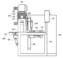
도 2는 본 발명에 따른 자동 톱 기계장치를 도시한 정면도.
도 3은 본 발명에 따른 자동 톱 기계장치를 도시한 평면도.
도 4는 본 발명에 따른 자동 톱 기계장치를 도시한 좌측면도.1 is a perspective view showing an automatic sawing machine according to the present invention;
2 is a front view showing an automatic sawing machine according to the present invention;
3 is a plan view showing an automatic sawing machine according to the present invention.
4 is a left side view of an automatic sawing machine according to the present invention.
본 발명에 따른 자동 톱 기계장치는, 지면으로부터 일정 높이로 설치되는 작업테이블과; 상기 작업테이블의 상부에 전후로 이송 가능하게 설치되어 소재를 절단위치로 이송시키는 이송부와; 상기 작업테이블의 상부에 길이방향으로 설치된 가이드부에 좌우로 이송 가능하게 설치되어 소재를 절단시키는 절단부와; 상기 가이드부의 전방에 일정한 간격을 두고 승강 가능하게 설치되어 상기 이송부를 통해 이송된 소재의 위치를 고정시키는 고정부와; 상기 작업테이블의 후방에 회동 가능하게 설치되어 상기 절단부를 통해 절단된 소재를 외부로 슬라이딩 배출시키는 배출부와; 상기 이송부, 절단부, 고정부 및 배출부의 동작을 자동 제어하는 컨트롤러를 포함하는 것을 특징으로 한다.The automatic sawing machine according to the present invention comprises: a work table installed at a predetermined height from the ground; A transfer unit installed at an upper portion of the work table so as to be movable back and forth to transfer the work to a cutting position; A cutting unit installed to the upper portion of the work table so as to be movable laterally to a guide portion provided in the longitudinal direction to cut the work; A fixing unit installed at a predetermined distance in front of the guide unit so as to be able to move up and down to fix the position of the material conveyed through the conveying unit; A discharge unit which is rotatably installed on the rear side of the work table and slidably discharges the material cut through the cutting unit to the outside; And a controller for automatically controlling the operations of the conveying portion, the cut portion, the fixing portion, and the discharging portion.
또한, 상기 이송부는 상기 작업테이블의 상부 양쪽에 각각 설치되어 정역모터에 의해 정역 회전되는 볼스크류와, 상기 볼스크류에 양단이 각각 연결되어 소재를 밀어주면서 절단위치를 조절하는 이송피더를 포함하는 것을 특징으로 한다.The conveying unit may include a ball screw installed on both sides of the upper portion of the work table and rotated in both forward and reverse directions by a forward and reverse motors and a conveying feeder connected to both ends of the ball screw to control the cutting position .
또한, 상기 가이드부는 상기 작업테이블의 상부로부터 일정 높이로 설치되는 지지프레임과, 상기 지지프레임의 상부에 설치된 LM가이드 및 모터와 연결되어 회전되는 볼스크류와, 상기 볼스크류에 결합되어 볼스크류의 회전방향에 따라 좌우로 왕복 이송되는 이송플레이트를 포함하는 것을 특징으로 한다.The guide unit may include a support frame installed at a predetermined height from the upper portion of the work table, a ball screw which is connected to the LM guide and motor provided on the support frame, And a transfer plate which is reciprocated in the left and right direction according to the direction of the transfer plate.
또한, 상기 절단부는 가이드부의 상측과 일단을 핀으로 결합하고 타단을 톱날용 액추에이터로 결합한 회동판에 고정된 모터의 동력이 원형 톱에 전달되어 고속으로 회전하게 구성되는 것을 특징으로 한다. In addition, the cutting portion is configured such that the power of the motor fixed to the rotary plate, which is coupled with the upper side and one end of the guide portion by a pin and the other end by a saw blade actuator, is transmitted to the circular saw and rotated at high speed.
또한, 상기 고정부는 공압 또는 유압에 의하여 작동하여 소재의 상부를 가압하는 고정실린더인 것을 특징으로 한다.In addition, the fixing unit is a fixed cylinder that operates by pneumatic or hydraulic pressure to press the upper part of the work.
또한, 상기 배출부는 상기 작업테이블의 상부 후단에 회동 가능하게 힌지 결합되는 회동테이블과, 상기 작업테이블의 후방 일측에 경사지게 설치되되 상기 회동테이블의 저면에 연결되어 회동테이블을 회동시키는 구동실린더를 포함하는 것을 특징으로The discharge unit may include a rotation table rotatably hinged to an upper rear end of the work table, and a driving cylinder that is inclined at a rear side of the work table and is connected to a bottom surface of the rotation table to rotate the rotation table Characterized by
또한, 상기 작업테이블의 일측에는 소재 절단작업 시 발생된 분진을 집진하기 위한 집진수단이 더 설치되며, 상기 집진수단은 상기 절단부의 일측에 근접 설치되어 분진을 흡입하는 흡입덕트와, 상기 흡입덕트에 연통되어 흡입덕트를 통해 흡입된 분진이 흡입 배출되는 분진 이송관과, 상기 분진 이송관의 일단에 연결되어 분진을 흡입하도록 흡입력을 제공하는 흡입팬과, 상기 분진 이송관을 통해 유입된 분진을 저장하는 집진기를 포함하는 것을 특징으로 한다.Further, dust collecting means for collecting dust generated during the material cutting operation is further provided on one side of the work table, and the dust collecting means includes a suction duct which is installed close to one side of the cut-out portion and sucks dust, A suction fan connected to one end of the dust transfer pipe to provide a suction force for sucking the dust, and a dust collecting unit for storing the dust introduced through the dust transfer pipe And a dust collector for collecting dust.
이하, 본 발명의 바람직한 실시예를 첨부된 도면을 참조하여 설명하면 다음과 같다.Hereinafter, preferred embodiments of the present invention will be described with reference to the accompanying drawings.
도 1은 본 발명에 따른 자동 톱 기계장치를 도시한 사시도이고, 도 2는 본 발명에 따른 자동 톱 기계장치를 도시한 정면도이며, 도 3은 본 발명에 따른 자동 톱 기계장치를 도시한 평면도이고, 도 4는 본 발명에 따른 자동 톱 기계장치를 도시한 좌측면도이다.FIG. 1 is a perspective view showing an automatic sawing machine according to the present invention, FIG. 2 is a front view showing an automatic sawing machine according to the present invention, FIG. 3 is a plan view showing an automatic sawing machine according to the present invention And Fig. 4 is a left side view of the automatic sawing machine according to the present invention.
도 1 내지 도 4에 도시된 바와 같이, 본 발명에 따른 자동 톱 기계장치는 작업테이블(10), 이송부(20), 가이드부(30), 절단부(40), 고정부(50), 배출부(60) 및 컨트롤러(70)를 포함한다.1 to 4, an automatic sawing machine according to the present invention includes a work table 10, a
먼저, 상기 작업테이블(10)은 지면으로부터 일정 높이로 설치되며 그 상부에 이송부(20), 절단부(40) 등이 배치되는 것으로, 지면 또는 작업장의 바닥에 구비되며 상면은 평편한 면을 이루는 함체 형상으로 이루어져 상부에 배치된 이송부(20), 절단부(40) 등을 지면 또는 바닥면으로부터 상방으로 이격된 위치에 배치되도록 지지한다.First, the work table 10 is installed at a predetermined height from the ground, and a
상기 작업테이블(10)의 일측에는 상기 이송부(20)의 이송시간, 이송간격 및 절단부(40)의 회전속도 등이 프로그램화되어 저장된 컨트롤러(70)가 설치된다. On one side of the work table 10, there is provided a
상기 이송부(20)는 상기 작업테이블(10)의 상부에 전후로 이송 가능하게 설치되어 소재를 절단위치로 이송시킨다.The
상기 이송부(20)는 상기 작업테이블(10)의 상부 양쪽에 각각 설치되어 정역모터(21)에 의해 정역 회전되는 볼스크류(22)와, 상기 볼스크류(22)에 양단이 각각 연결되어 소재를 밀어주면서 절단위치를 조절하는 이송피더(23)를 포함한다.The
상기 이송피더(23)는 상기 작업테이블(10)의 상부면에 길이방향을 따라 설치되며 작업테이블(10에 면접되도록 직사각형의 플레이트 형태로 이루어지며, 그 양단에는 상기 볼스크류(22)에 나사 결합되도록 너트(231)가 형성된다.The
즉, 상기 이송부(20)는 작업자에 의해 절단 대상물인 소재를 작업테이블(10)의 상부에 투입시키면 컨트롤러(70)의 제어에 의해 구동되는 정역모터(21)의 회전력을 제공받아 볼스크류(22)가 회전하게 되면, 컨트롤러(70)에 의해 미리 설정된 절단 폭 치수에 따라 상기 이송피더(23)가 전후로 이송하면서 소재를 절단위치까지 이송하게 된다.That is, when the worker inserts the material to be cut into the upper portion of the work table 10 by the operator, the
상기 가이드부(30)는 상기 작업테이블(10)의 상부에서도 후방에 길이방향으로 설치되며 작업테이블(10)로부터 일정 높이로 이격 설치된다.The
상기 가이드부(30)는 상기 작업테이블(10)의 상부로부터 일정 높이로 설치되는 지지프레임(31)과, 상기 지지프레임(31)의 상부에 설치된 LM가이드(32) 및 모터(33)와 연결되어 회전되는 볼스크류(34)와, 상기 볼스크류(34)에 결합되어 볼스크류(34)의 회전방향에 따라 좌우로 왕복 이송되는 이송플레이트(35)를 포함한다.The
상기 지지프레임(31)은 상기 작업테이블(10)로부터 일정 높이로 이격 설치되도록 하부에 다수의 수직지지대(311)가 설치되며, 상부에는 절단부(40)의 원형 톱(44)이 좌우로 이송할 수 있도록 개구부(미도시)가 형성된다.A plurality of
상기 LM가이드(32)는 상기 지지프레임(31)의 상부면에 길이방향으로 복수개가 서로 이격되게 설치된다.The
상기 이송플레이트(35)는 상기 LM가이드(32)에 의해 안내되어 좌우로 이송하게 되며 저면에는 상기 볼스크류(34)와 나사체결되는 너트(미도시)와 상기 LM가이드(32)에 결합되는 LM블록(미도시)이 형성된다.The
상기와 같이 구성되는 가이드부(30)는 소재의 절단 시 상기 절단부(40)의 원형 톱(44)을 직선방향으로 이송 안내하는 역할을 하게 된다.The
상기 절단부(40)는 상기 작업테이블(10)의 상부에 길이방향으로 설치된 가이드부(30)에 좌우로 이송 가능하게 설치되어 소재를 절단시킨다.The
상기 절단부(40)는 가이드부(30)의 상측과 일단을 핀으로 결합하고 타단을 톱날용 액추에이터(41)로 결합한 회동판(42)에 고정된 모터(43)의 동력이 원형 톱(44)에 전달되어 고속으로 회전하게 구성된다.The
상기 원형 톱(44)의 상부 외주연에는 소재가 유입되는 전방을 제외한 나머지 부분에 안전커버를 씌워 회전하는 원형 톱(44)에 상해를 입는 등의 산업재해를 방지할 수 있게 한다.The
상기 원형 톱(44)은 소재 절단에 사용되도록 외주연에 다수의 톱날이 등간격으로 형성된 통상의 원판 형태로 이루어진다.The
상기 원형 톱(44)의 중심에는 벨트풀리가 구비된 축이 연결되고, 상기 벨트풀리는 상기 모터(43)의 회전축에 구비된 벨트풀리와 벨트로 연결되어 모터(43)의 구동에 의한 회전력이 전달된다.A shaft provided with a belt pulley is connected to the center of the
상기 고정부(50)는 상기 가이드부(30)의 전방에 일정한 간격을 두고 승강 가능하게 설치되어 상기 이송부(20)를 통해 이송된 소재의 위치를 고정시킨다.The
상기 고정부(50)는 공압 또는 유압에 의하여 작동하여 소재의 상부를 가압하는 고정실린더로 구성되는 것이 바람직하다. 즉 상기 고정부(50)는 컨트롤러(70)의 제어에 의해 작동되며 고정실린더의 구성요소인 로드의 선단이 하부를 향해 신장되면서 절단위치에 정지된 소재를 가압하여 소재를 고정시킨다.The
상기 배출부(60)는 상기 작업테이블(10)의 후방에 회동 가능하게 설치되어 상기 절단부(40)를 통해 절단된 소재를 외부로 슬라이딩 배출시킨다.The
상기 배출부(60)는 상기 작업테이블(10)의 상부 후단에 회동 가능하게 힌지 결합되는 회동테이블(61)과, 상기 작업테이블(10)의 후방 일측에 경사지게 설치되되 상기 회동테이블(61)의 저면에 연결되어 회동테이블(61)을 회동시키는 구동실린더(62)를 포함한다.The
즉, 상기 절단부(40)를 통해 소재 절단작업이 완료되면 상기 컨트롤러(70)의 제어에 의해 구동실린더(62)가 하강 작동하면서 수평상태를 유지했던 회동테이블(61)이 하향 회동하면서 절단물이 슬라이딩되어 적재함으로 수납되게 된다.That is, when the workpiece cutting operation is completed through the
상기 컨트롤러(70)는 상기 이송부(20), 절단부(40), 고정부(50) 및 배출부(60)의 동작을 자동 제어하게 된다. The
즉, 상기 컨트롤러(70)는 이송부(20)의 이송시간, 이송속도 및 이송거리에 따라 절단부(40)의 원형 톱(44)이 승강되어 소재의 절단이 이루어지도록 프로그램화된 정보가 저장되어 있고, 상기 이송부(20)에 의해 절단위치로 이송된 상태에서 소재의 위치를 고정하기 위해 작동되는 고정부(50)의 작동시간 등이 저장되어 있다. 그 밖에 상기 컨트롤러(70)는 비상 시 장치를 정지시키기 위한 비상정지버튼은 물론 작동을 진행시키기 위한 작동스위치 등을 포함한다.That is, the
한편, 상기 작업테이블(10)의 일측에는 소재 절단작업 시 발생된 분진을 집진하기 위한 집진수단(80)이 더 설치되는 것이 바람직하다.Meanwhile, it is preferable that dust collecting means (80) for collecting dust generated in the material cutting operation is further provided at one side of the work table (10).
상기 집진수단(80)은 상기 절단부(40)의 일측에 근접 설치되어 분진을 흡입하는 흡입덕트(81)와, 상기 흡입덕트(81)에 연통되어 흡입덕트(81)를 통해 흡입된 분진이 흡입 배출되는 분진 이송관(82)과, 상기 분진 이송관(82)의 일단에 연결되어 분진을 흡입하도록 흡입력을 제공하는 흡입팬(83)과, 상기 분진 이송관(82)을 통해 유입된 분진을 저장하는 집진기(84)를 포함한다.The dust collecting means 80 includes a
이하, 본 발명에 따른 자동 톱 기계장치의 작동을 설명하면 다음과 같다.Hereinafter, the operation of the automatic saw machine according to the present invention will be described.
먼저, 작업자에 의해 컨트롤러(70)를 조작하여 이송부(20), 절단부(40), 고정부(50) 및 배출부(60)의 작동을 위한 설정값을 셋팅한다.First, the
이후, 작업자가 절단 대상물인 소재를 작업테이블(10)의 상부에 올려놓고 컨트롤러(70)의 작동스위치를 작동시킨다.Thereafter, the worker puts the material, which is the object to be cut, on the work table 10 and operates the operation switch of the
컨트롤러(70)의 제어에 의해 이송피더(23)가 정역모터(21)에 의해 회전 구동되는 볼스크류(22)를 따라 후방으로 이송하면서 소재를 절단위치까지 밀어준다.The feeding
소재가 절단위치에 도달하게 되면, 다수의 고정부(50)가 하강하면서 소재의 상부면을 가압하여 고정한다.When the material reaches the cutting position, the plurality of fixing
이후, 절단부(40)의 원형 톱(44)을 소재의 절단위치로 하강시킨 상태에서 가이드부(30)의 모터(33)에 의해 회전력을 제공받은 볼스크류(22)가 회전을 하고 LM가이드(32)를 따라 이송플레이트(35)가 이송함과 동시에 이송플레이트(35)에 고정된 원형 톱(44)이 회전 구동되면서 소재를 절단한다. 소재를 절단하는 과정에서 절삭 칩과 분진은 집진수단(80)에 의해 수거된다.The ball screw 22 provided with the rotational force by the
절단이 완료된 소재는 배출되되 구동실린더(62)의 작동과 함께 회동테이블(61)의 후단이 하향으로 기울어지면서 경사각을 형성하여 절단물은 슬라이딩되면서 적재함에 수납된다.The cut material is discharged, but the rear end of the rotation table 61 is inclined downwardly together with the operation of the driving
또한, 소재는 설정값에 따라 절단 동작을 반복하는데 한 개의 절단 동작 및 배출을 완료하면, 고정부(50)는 상승하고 이송피더(23)는 절단 폭만큼 이송되며, 다시 고정부(50)가 하강하여 소재를 고정 지지하고 원형 톱(44)이 이송하면서 절단작업을 완료하며, 절단된 소재는 자동 배출하는 과정을 반복 동작한다.When the cutting operation is repeated according to the set value and the cutting operation and discharge are completed, the fixing
이와 같이, 본 발명에 따른 자동 톱 기계장치는 절단 대상물을 일정한 크기로 연속적으로 자동 절단할 수 있어 작업시간의 단축 및 사용의 편리성을 높일 수 있으며 이와 함께 이송 및 절단공정이 자동으로 이루어져 각종 안전사고를 예방할 수 있는 것이다.As described above, the automatic sawing machine according to the present invention can continuously cut the object to be cut automatically to a predetermined size, thereby shortening the working time and improving the convenience of use. In addition, the feeding and cutting processes are automatically performed, It can prevent accidents.
본 발명은 첨부된 도면을 참조하여 바람직한 실시예를 중심으로 기술되었지만 당업자라면 이러한 기재로부터 본 발명의 범주를 벗어남이 없이 다양한 수정 및 변형이 가능할 것이다.
While the present invention has been particularly shown and described with reference to exemplary embodiments thereof, it is evident that many alternatives, modifications and variations will be apparent to those skilled in the art without departing from the scope of the invention.
10 : 작업테이블
20 : 이송부
21 : 정역모터
22 : 볼스크류
23 : 이송피더
231 : 너트
30 : 가이드부
31 : 지지프레임
311 : 수직지지대
32 : LM가이드
33 : 모터
34 : 볼스크류
35 : 이송플레이트
40 : 절단부
41 : 액추에이터
42 : 회동판
43 : 모터
44 : 원형 톱
50 : 고정부
60 : 배출부
61 : 회동테이블
62 : 구동실린더
70 : 컨트롤러
80 : 집진수단
81 : 흡입덕트
82 : 분진 이송관
83 : 흡입팬
84 : 집진기10: Work table
20:
21: Inverse motor
22: Ball Screw
23: Feed feeder
231: Nuts
30: guide portion
31: Support frame
311: Vertical support
32: LM Guide
33: Motor
34: Ball Screw
35: Transfer plate
40:
41: Actuator
42: Rotary plate
43: Motor
44: Circular saw
50:
60:
61: Rotating table
62: drive cylinder
70: controller
80: dust collecting means
81: Suction duct
82: Dust transfer pipe
83: Suction fan
84: Dust collector
Claims (7)
상기 작업테이블(10)의 상부에 전후로 이송 가능하게 설치되어 소재를 절단위치로 이송시키는 이송부(20)와;
상기 작업테이블(10)의 상부에 길이방향으로 설치된 가이드부(30)에 좌우로 이송 가능하게 설치되어 소재를 절단시키는 절단부(40)와;
상기 가이드부(30)의 전방에 일정한 간격을 두고 승강 가능하게 설치되어 상기 이송부(20)를 통해 이송된 소재의 위치를 고정시키는 고정부(50)와;
상기 작업테이블(10)의 후방에 회동 가능하게 설치되어 상기 절단부(40)를 통해 절단된 소재를 외부로 슬라이딩 배출시키는 배출부(60)와;
상기 이송부(20), 절단부(40), 고정부(50) 및 배출부(60)의 동작을 자동 제어하는 컨트롤러(70)를 포함하는 것을 특징으로 하는 자동 톱 기계장치.
A work table (10) installed at a predetermined height from the ground;
A transfer unit 20 installed at an upper portion of the work table 10 so as to be transported back and forth to transfer the work to a cutting position;
A cutting unit 40 installed on the guide table 30 installed in the longitudinal direction on the upper portion of the work table 10 so as to be movable laterally to cut the work;
A fixing unit 50 installed at a predetermined distance in front of the guide unit 30 so as to be able to move up and down to fix the position of the material conveyed through the conveying unit 20;
A discharge unit 60 rotatably installed behind the work table 10 and slidably discharging the cut material through the cut unit 40;
And a controller (70) for automatically controlling the operations of the transferring unit (20), the cutting unit (40), the fixing unit (50), and the discharging unit (60).
상기 이송부(20)는 상기 작업테이블(10)의 상부 양쪽에 각각 설치되어 정역모터(21)에 의해 정역 회전되는 볼스크류(22)와, 상기 볼스크류(22)에 양단이 각각 연결되어 소재를 밀어주면서 절단위치를 조절하는 이송피더(23)를 포함하는 것을 특징으로 하는 자동 톱 기계장치.
The method according to claim 1,
The transfer unit 20 includes a ball screw 22 installed on both sides of the upper portion of the work table 10 and rotated in normal and reverse directions by a normal and reverse motors 21 and both ends connected to the ball screw 22, And a feeding feeder (23) for adjusting the cutting position while pushing the feeding feeder (23).
상기 가이드부(30)는 상기 작업테이블(10)의 상부로부터 일정 높이로 설치되는 지지프레임(31)과, 상기 지지프레임(31)의 상부에 설치된 LM가이드(32) 및 모터(33)와 연결되어 회전되는 볼스크류(34)와, 상기 볼스크류(34)에 결합되어 볼스크류(34)의 회전방향에 따라 좌우로 왕복 이송되는 이송플레이트(35)를 포함하는 것을 특징으로 하는 자동 톱 기계장치.
The method according to claim 1,
The guide unit 30 includes a support frame 31 installed at a predetermined height from the upper portion of the work table 10 and an LM guide 32 and a motor 33 installed on the support frame 31 And a transfer plate (35) coupled to the ball screw (34) and reciprocated in the left and right direction in accordance with the rotational direction of the ball screw (34). The automatic sawing machine .
상기 절단부(40)는 가이드부(30)의 상측과 일단을 핀으로 결합하고 타단을 톱날용 액추에이터(41)로 결합한 회동판(42)에 고정된 모터(43)의 동력이 원형 톱(44)에 전달되어 고속으로 회전하게 구성되는 것을 특징으로 하는 자동 톱 기계장치.
The method according to claim 1,
The cut portion 40 is formed by cutting the power of the motor 43 fixed to the rotary plate 42 which is coupled with the upper side and one end of the guide portion 30 by a pin and the other end by a saw blade actuator 41, And is rotated at a high speed.
상기 고정부(50)는 공압 또는 유압에 의하여 작동하여 소재의 상부를 가압하는 고정실린더인 것을 특징으로 하는 자동 톱 기계장치.
The method according to claim 1,
Wherein the fixing part (50) is a fixed cylinder which is operated by pneumatic or hydraulic pressure to press the upper part of the work.
상기 배출부(60)는 상기 작업테이블(10)의 상부 후단에 회동 가능하게 힌지 결합되는 회동테이블(61)과, 상기 작업테이블(10)의 후방 일측에 경사지게 설치되되 상기 회동테이블(61)의 저면에 연결되어 회동테이블(61)을 회동시키는 구동실린더(62)를 포함하는 것을 특징으로 하는 자동 톱 기계장치.
The method according to claim 1,
The discharge unit 60 includes a rotary table 61 rotatably hinged to the upper rear end of the work table 10 and a rotary table 61 installed at an obliquely rear side of the work table 10, And a drive cylinder (62) connected to the bottom surface for rotating the rotation table (61).
상기 작업테이블(10)의 일측에는 소재 절단작업 시 발생된 분진을 집진하기 위한 집진수단(80)이 더 설치되며,
상기 집진수단(80)은 상기 절단부(40)의 일측에 근접 설치되어 분진을 흡입하는 흡입덕트(81)와, 상기 흡입덕트(81)에 연통되어 흡입덕트(81)를 통해 흡입된 분진이 흡입 배출되는 분진 이송관(82)과, 상기 분진 이송관(82)의 일단에 연결되어 분진을 흡입하도록 흡입력을 제공하는 흡입팬(83)과, 상기 분진 이송관(82)을 통해 유입된 분진을 저장하는 집진기(84)를 포함하는 것을 특징으로 하는 자동 톱 기계장치.The method according to claim 1,
A dust collecting means (80) for collecting dust generated in the work of cutting the work is installed at one side of the work table (10)
The dust collecting means 80 includes a suction duct 81 which is installed in close proximity to one side of the cutout 40 and sucks in dust and dust which is in communication with the suction duct 81 and sucked through the suction duct 81, A suction fan 83 connected to one end of the dust transfer pipe 82 to provide a suction force to suck the dust, and a dust suction pipe 83 connected to one end of the dust transfer pipe 82, And a dust collector (84) for storing dust.
Priority Applications (1)
| Application Number | Priority Date | Filing Date | Title |
|---|---|---|---|
| KR1020160022440A KR20170100701A (en) | 2016-02-25 | 2016-02-25 | Automatic saw machine |
Applications Claiming Priority (1)
| Application Number | Priority Date | Filing Date | Title |
|---|---|---|---|
| KR1020160022440A KR20170100701A (en) | 2016-02-25 | 2016-02-25 | Automatic saw machine |
Publications (1)
| Publication Number | Publication Date |
|---|---|
| KR20170100701A true KR20170100701A (en) | 2017-09-05 |
Family
ID=59924982
Family Applications (1)
| Application Number | Title | Priority Date | Filing Date |
|---|---|---|---|
| KR1020160022440A KR20170100701A (en) | 2016-02-25 | 2016-02-25 | Automatic saw machine |
Country Status (1)
| Country | Link |
|---|---|
| KR (1) | KR20170100701A (en) |
Cited By (6)
| Publication number | Priority date | Publication date | Assignee | Title |
|---|---|---|---|---|
| CN107695439A (en) * | 2017-10-12 | 2018-02-16 | 嘉兴林升液压工具有限公司 | A kind of automatic charging device of circular saw cutting machine |
| CN108380970A (en) * | 2018-05-10 | 2018-08-10 | 泉州弘正机械有限公司 | A kind of feeding equipment applied in steel pipe multitube sawing machine |
| CN109128350A (en) * | 2018-10-29 | 2019-01-04 | 泰州驰骏智能设备有限公司 | A kind of automatic pipe cutting equipment |
| WO2021253474A1 (en) * | 2020-06-15 | 2021-12-23 | 南京唐壹信息科技有限公司 | New type aluminum profile cutting auxiliary device |
| CN116277207A (en) * | 2022-12-02 | 2023-06-23 | 保定达捷机械设备有限公司 | Cutting equipment for polyurethane foam composite board |
| KR20230143730A (en) | 2022-04-06 | 2023-10-13 | 김지태 | Electric circular saw with dust collecting member for tool storage |
-
2016
- 2016-02-25 KR KR1020160022440A patent/KR20170100701A/en not_active Application Discontinuation
Cited By (8)
| Publication number | Priority date | Publication date | Assignee | Title |
|---|---|---|---|---|
| CN107695439A (en) * | 2017-10-12 | 2018-02-16 | 嘉兴林升液压工具有限公司 | A kind of automatic charging device of circular saw cutting machine |
| CN108380970A (en) * | 2018-05-10 | 2018-08-10 | 泉州弘正机械有限公司 | A kind of feeding equipment applied in steel pipe multitube sawing machine |
| CN109128350A (en) * | 2018-10-29 | 2019-01-04 | 泰州驰骏智能设备有限公司 | A kind of automatic pipe cutting equipment |
| CN109128350B (en) * | 2018-10-29 | 2024-02-09 | 泰州驰骏智能设备有限公司 | Automatic pipe cutting equipment |
| WO2021253474A1 (en) * | 2020-06-15 | 2021-12-23 | 南京唐壹信息科技有限公司 | New type aluminum profile cutting auxiliary device |
| KR20230143730A (en) | 2022-04-06 | 2023-10-13 | 김지태 | Electric circular saw with dust collecting member for tool storage |
| CN116277207A (en) * | 2022-12-02 | 2023-06-23 | 保定达捷机械设备有限公司 | Cutting equipment for polyurethane foam composite board |
| CN116277207B (en) * | 2022-12-02 | 2024-05-28 | 巨灵(南京)智能科技有限公司 | Cutting equipment for polyurethane foam composite board |
Similar Documents
| Publication | Publication Date | Title |
|---|---|---|
| KR20170100701A (en) | Automatic saw machine | |
| KR20150072664A (en) | Heavy board cutting device | |
| GB2041822A (en) | Band saw blade guide assembly | |
| CN106313185A (en) | Board cutting device with feeding mechanism | |
| KR20150084357A (en) | Automatic two-sided material supply top grinder | |
| CN108380726B (en) | automatic material conveying and cutting machine | |
| CN211489833U (en) | Plate shearing machine with strong adaptability | |
| CN101168257B (en) | Horizontal band saw cutting machine | |
| CN215968965U (en) | Vertical paper cutter | |
| CN109203085B (en) | High-speed optimized cutting and finish planing production line | |
| CN113996865A (en) | Automatic horizontal metal band sawing machine of pay-off | |
| CN211361625U (en) | Woodworking drill processing equipment | |
| KR20150002537U (en) | Heavy board cutting device | |
| CN201168984Y (en) | Horizontal type band saws cutter | |
| KR20170139834A (en) | A copper round bar grinding apparetus for lathe | |
| CN113305225B (en) | Bending machine with conveying function | |
| CN214981357U (en) | Arc cutting equipment | |
| CN214352711U (en) | Pipe cutting device | |
| CN201645574U (en) | Multifunctional woodworking machine tool | |
| CN114131108A (en) | Plate shearing machine with cutting quick positioning device | |
| CN210099248U (en) | Laser cutting device for metal plate | |
| CN218284919U (en) | Trimming device is used in processing of plastic disc | |
| CN210702868U (en) | Cutting machine | |
| JP2987697B2 (en) | Four-side finishing sawmill | |
| CN218611701U (en) | Equipment for machining inner hole of bushing |
Legal Events
| Date | Code | Title | Description |
|---|---|---|---|
| A201 | Request for examination | ||
| E902 | Notification of reason for refusal | ||
| E601 | Decision to refuse application |