KR20170099091A - Built-sheet structure of the construction and building structures - Google Patents
Built-sheet structure of the construction and building structures Download PDFInfo
- Publication number
- KR20170099091A KR20170099091A KR1020160021032A KR20160021032A KR20170099091A KR 20170099091 A KR20170099091 A KR 20170099091A KR 1020160021032 A KR1020160021032 A KR 1020160021032A KR 20160021032 A KR20160021032 A KR 20160021032A KR 20170099091 A KR20170099091 A KR 20170099091A
- Authority
- KR
- South Korea
- Prior art keywords
- spacer clip
- support
- support base
- interior
- flat plate
- Prior art date
Links
- 238000010276 construction Methods 0.000 title claims abstract description 27
- 239000000463 material Substances 0.000 claims abstract description 45
- 125000006850 spacer group Chemical group 0.000 claims abstract description 39
- 230000003014 reinforcing effect Effects 0.000 claims description 10
- 238000004049 embossing Methods 0.000 claims description 9
- 230000002787 reinforcement Effects 0.000 claims description 7
- 238000003780 insertion Methods 0.000 claims description 3
- 230000037431 insertion Effects 0.000 claims description 3
- 230000035515 penetration Effects 0.000 claims description 3
- 238000000034 method Methods 0.000 claims 5
- 238000005452 bending Methods 0.000 claims 1
- 230000002708 enhancing effect Effects 0.000 abstract description 4
- 229910000831 Steel Inorganic materials 0.000 description 2
- 239000010959 steel Substances 0.000 description 2
- 239000002969 artificial stone Substances 0.000 description 1
- 230000003111 delayed effect Effects 0.000 description 1
- 239000002184 metal Substances 0.000 description 1
- 238000012986 modification Methods 0.000 description 1
- 230000004048 modification Effects 0.000 description 1
- 230000000717 retained effect Effects 0.000 description 1
- 239000011435 rock Substances 0.000 description 1
- XLYOFNOQVPJJNP-UHFFFAOYSA-N water Substances O XLYOFNOQVPJJNP-UHFFFAOYSA-N 0.000 description 1
- 239000002023 wood Substances 0.000 description 1
Images


Classifications
-
- E—FIXED CONSTRUCTIONS
- E04—BUILDING
- E04F—FINISHING WORK ON BUILDINGS, e.g. STAIRS, FLOORS
- E04F13/00—Coverings or linings, e.g. for walls or ceilings
- E04F13/07—Coverings or linings, e.g. for walls or ceilings composed of covering or lining elements; Sub-structures therefor; Fastening means therefor
- E04F13/08—Coverings or linings, e.g. for walls or ceilings composed of covering or lining elements; Sub-structures therefor; Fastening means therefor composed of a plurality of similar covering or lining elements
- E04F13/0801—Separate fastening elements
-
- E04B1/40—
-
- E—FIXED CONSTRUCTIONS
- E04—BUILDING
- E04B—GENERAL BUILDING CONSTRUCTIONS; WALLS, e.g. PARTITIONS; ROOFS; FLOORS; CEILINGS; INSULATION OR OTHER PROTECTION OF BUILDINGS
- E04B2/00—Walls, e.g. partitions, for buildings; Wall construction with regard to insulation; Connections specially adapted to walls
- E04B2/74—Removable non-load-bearing partitions; Partitions with a free upper edge
-
- E—FIXED CONSTRUCTIONS
- E04—BUILDING
- E04B—GENERAL BUILDING CONSTRUCTIONS; WALLS, e.g. PARTITIONS; ROOFS; FLOORS; CEILINGS; INSULATION OR OTHER PROTECTION OF BUILDINGS
- E04B9/00—Ceilings; Construction of ceilings, e.g. false ceilings; Ceiling construction with regard to insulation
- E04B9/06—Ceilings; Construction of ceilings, e.g. false ceilings; Ceiling construction with regard to insulation characterised by constructional features of the supporting construction, e.g. cross section or material of framework members
-
- E—FIXED CONSTRUCTIONS
- E04—BUILDING
- E04F—FINISHING WORK ON BUILDINGS, e.g. STAIRS, FLOORS
- E04F2201/00—Joining sheets or plates or panels
- E04F2201/05—Separate connectors or inserts, e.g. pegs, pins, keys or strips
- E04F2201/0511—Strips or bars, e.g. nailing strips
-
- E—FIXED CONSTRUCTIONS
- E04—BUILDING
- E04F—FINISHING WORK ON BUILDINGS, e.g. STAIRS, FLOORS
- E04F2201/00—Joining sheets or plates or panels
- E04F2201/05—Separate connectors or inserts, e.g. pegs, pins, keys or strips
- E04F2201/0517—U- or C-shaped brackets and clamps
Landscapes
- Engineering & Computer Science (AREA)
- Architecture (AREA)
- Civil Engineering (AREA)
- Structural Engineering (AREA)
- Physics & Mathematics (AREA)
- Electromagnetism (AREA)
- Finishing Walls (AREA)
Abstract
The present invention relates to a construction method for an interior material of a building structure.
To this end, according to the present invention, there is provided an interior material construction structure for a building structure, wherein a support base is coupled to both sides of a spacer clip and an interior finishing material is coupled to the outside of the support base, Wherein a front and rear vertical plates longer than the length of the flat plate in the longitudinal direction are bent at right angles to the lower side so that support base engaging spaces are respectively formed on both sides of the flat plate in the longitudinal direction and the supporting base has a rectangular hollow shape, And the latching grooves are formed in the longitudinal direction at the portions where the rear vertical plates come into contact with each other.
Accordingly, the present invention enables selective use of a wall-interior finishing material and a vestibule interior finishing material on a support provided on both sides of a spacer clip, thereby enhancing compatibility and enhancing workability and reducing a construction cost.
Description
[0001] The present invention relates to an interior material construction structure of a building structure, in particular, a structure in which a supporting base is coupled to both sides of a spacer clip, an interior finishing material is coupled to the outer side of each support, The finishing material is combined with a step-like shape so as to have a ceiling function for distinguishing the upper space.
Generally, the interior of a building is divided into a wall or a ceiling using a built-in finishing material made of metal, wood, or artificial stone.
The space defined by the front, rear, left, and right sides of the inside of the building structure includes two rows of studs vertically disposed between the upper and lower runners provided in the roof slab and the floor slab, respectively, to form a channel, A built-in wall-covering material is attached to the outside of the stud.
In the upper and lower spaces defined inside the building structure, a hanger bolt is embedded in a ceiling slab, a carrying channel is connected to the lower part of the hanger in a state where the upper part of the hanger is joined to the hanger bolt, Board, a rock surface bath, and the like.
However, in order to separate the inner space of the building structure, there is a problem that it is inconvenient to separately provide the wall-interior finishing material, the ceiling built-in finishing material, and the respective components for constructing the interior wall finishing material.
In addition, there is another problem that the work is delayed due to the difference in the construction method, and there is another problem that the cost is further increased.
The present invention enables selective use of the wall-interior finishing material and the vestibule interior finishing material, which divide the interior space of the building structure into front, back, left and right, and upper, by means of a support provided on both sides of one spacer clip, This makes it possible to increase the workability and reduce the construction cost.
The present invention provides an interior material construction structure for a building structure having a
The
The front and rear
In addition, the front and rear
The
The
The present invention can provide a wall function by providing a wall-built-in finishing material on the outer side of the support, while the support bars coupled to both sides of the spacer clip are provided in a vertical shape.
In addition, it is possible to provide a ceiling function by providing a ceiling built-in finishing material on the outer side of the spacer clip so that the supports coupled to both sides of the spacer clip are provided in the form of a horizontal step.
In addition, it is possible to selectively use the wall-interior finishing material and the vestibule interior finishing material on the supports provided on both sides of one spacer clip, thereby enhancing compatibility.
In addition to this, it is possible to further improve the workability and further reduce the construction cost.
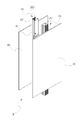
1 is a perspective view showing a construction of an interior material of a building according to the present invention;
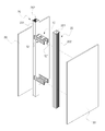
FIG. 2 is a perspective view illustrating the interior construction of the building according to the present invention. FIG.
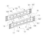
3 is a perspective view showing a spacer clip in the interior material construction of the building structure according to the present invention.
4 is a bottom perspective view showing a spacer clip in the interior material construction of the building structure according to the present invention.
5 is a cross-sectional view illustrating an interior material construction structure of a building structure according to the present invention.
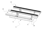
6 is a perspective view showing another embodiment of the interior material construction structure of the building structure according to the present invention.
7 is a bottom perspective view showing another embodiment of the interior material construction structure of the building structure according to the present invention.
Embodiments of the present invention will now be described with reference to the accompanying drawings.
FIG. 1 is a perspective view showing a construction of an interior material of a building according to the present invention, FIG. 2 is a perspective view showing an interior material construction of the building according to the present invention, and FIG. FIG. 4 is a bottom perspective view showing a spacer clip in the interior material construction of the building structure according to the present invention, and FIG. 5 is a perspective view showing the internal structure of the interior structure of the building according to the present invention. Fig.
The interior construction of the building structure according to the present invention can be used selectively for the wall-interior finishing material and the vestibule interior finishing material, thereby enhancing the compatibility and improving the workability and reducing the construction cost. FIGS. 1 to 5 The
The
The
A plurality of flat
Reinforced
The front and rear
The front and rear
The vertical plate reinforcement embossing 123 is formed vertically and horizontally on the front and
A plurality of through
The
The weight of the
In the portions where the front and rear
The
FIG. 6 is a perspective view showing another embodiment of the interior material construction construction of the building structure according to the present invention, and FIG. 7 is a bottom perspective view showing another embodiment of the interior material construction construction of the building structure according to the present invention.
In this invention, the
In this case, the end of the
While the present invention has been particularly shown and described with reference to exemplary embodiments thereof, it will be understood by those of ordinary skill in the art that various changes and modifications may be made therein without departing from the spirit and scope of the invention. The technical idea of the present invention should not be construed as being limited.
10: spacer clip
11: Reputation
12,12 ': Before and after water treatment
13: Supporting space
20: Support
30: Built-in finishing material
201:
Claims (6)
Since the spacer clip 10 is bent at right angles to the lower portion of the front and rear plates 12 and 12 'longer than the longitudinal length of the plate 11 on both sides of the plate 11 in the longitudinal direction, The supporting plate 20 has a square hollow shape, and the front and rear plates 12 and 12 'abut against each other in the longitudinal direction of the flat plate 11, Wherein a latching groove (201) is formed in a longitudinal direction in each of the projecting portions.
The flat plate 11 of the spacer clip 10 has a rectangular shape and is formed by bending a support base support piece 111 bent downward at four corners in the longitudinal direction, And a reinforcing notch groove 113 is formed at a corner where the vertical plates 12 and 12 'of the flat plate 11 are bent before and after the flat plate 11, respectively The construction of the interior of the building.
The front and rear vertical plates 12 and 12 'in which the support space 13 is located are provided with fastening pieces 121 and 121' at both ends thereof, 126 and 126 which are formed to be vertically formed and hooked on the retaining grooves 201 of the support table 20 and which are bent obliquely toward the upper inner side at the lower ends of the front and rear vertical plates 12 and 12 ' Wherein the reinforcing pieces 126 and 126 'are formed such that both longitudinal ends of the reinforcing pieces 126 and 126' coincide with the supporting piece receiving pieces 111 formed on the flat plate 11. [ .
The front and rear vertical plates 12 and 12 'are formed with insertion guides 122 and 122', respectively, which are extended outward at the entrance side, and the front and rear vertical plates 12 and 12 ' A plurality of through holes 124 are formed between the vertical plate reinforcement embossings 123, and the plurality of through holes 124 are formed between the vertical plate reinforcement embossings 123, The through hole 124 is formed with an outwardly convex penetration guide 125 to guide the end of the screw S passing through the front vertical plate 12 or the rear vertical plate 12 ' Construction of the interior structure of the building.
The supporter 20 is vertically or laterally or vertically arranged in two rows by means of a spacer clip 10 and is provided with a corrugated concavo-convex portion 202 provided on the outside of the two support rods 20 And the back surface of the built-in finishing material 30 are coupled to each other so as to have a function of a wall W dividing the space into one space and the other space of the building structure.
The support base 20 is horizontally arranged in two rows by the spacer clip 10 so that the end of the support base 20 positioned below the spacer clip 10 coincides with the spacer clip 10 And the rear surface of the built-in finishing material 20 is butted against the front surface of the spacer clip 10 and the support rods 20 provided above and below the spacer clip 10, And a ceiling (C) divided into a plurality of sections.
Priority Applications (1)
| Application Number | Priority Date | Filing Date | Title |
|---|---|---|---|
| KR1020160021032A KR101783870B1 (en) | 2016-02-23 | 2016-02-23 | Built-sheet structure of the construction and building structures |
Applications Claiming Priority (1)
| Application Number | Priority Date | Filing Date | Title |
|---|---|---|---|
| KR1020160021032A KR101783870B1 (en) | 2016-02-23 | 2016-02-23 | Built-sheet structure of the construction and building structures |
Publications (2)
| Publication Number | Publication Date |
|---|---|
| KR20170099091A true KR20170099091A (en) | 2017-08-31 |
| KR101783870B1 KR101783870B1 (en) | 2017-10-10 |
Family
ID=59761220
Family Applications (1)
| Application Number | Title | Priority Date | Filing Date |
|---|---|---|---|
| KR1020160021032A KR101783870B1 (en) | 2016-02-23 | 2016-02-23 | Built-sheet structure of the construction and building structures |
Country Status (1)
| Country | Link |
|---|---|
| KR (1) | KR101783870B1 (en) |
Cited By (1)
| Publication number | Priority date | Publication date | Assignee | Title |
|---|---|---|---|---|
| KR20200006306A (en) * | 2018-07-10 | 2020-01-20 | 주식회사 포스코 | Frame structure and panel structure and frame connecting structure |
Families Citing this family (2)
| Publication number | Priority date | Publication date | Assignee | Title |
|---|---|---|---|---|
| KR20230111449A (en) | 2022-01-18 | 2023-07-25 | 임인덕 | Interior/exterior material fastening unit for construction methods |
| KR200496643Y1 (en) | 2022-01-18 | 2023-03-22 | 임인덕 | Interior material fastening unit for construction |
Family Cites Families (3)
| Publication number | Priority date | Publication date | Assignee | Title |
|---|---|---|---|---|
| KR101069588B1 (en) * | 2011-01-14 | 2011-10-05 | 변각균 | Structure of the lightweight steel frame |
| KR101234675B1 (en) * | 2011-06-30 | 2013-02-22 | 김성주 | Clip for ceiling finish establishment |
| KR101341846B1 (en) * | 2013-09-09 | 2014-01-03 | 김성주 | Waterproof wall of the basement building structures |
-
2016
- 2016-02-23 KR KR1020160021032A patent/KR101783870B1/en active IP Right Grant
Cited By (1)
| Publication number | Priority date | Publication date | Assignee | Title |
|---|---|---|---|---|
| KR20200006306A (en) * | 2018-07-10 | 2020-01-20 | 주식회사 포스코 | Frame structure and panel structure and frame connecting structure |
Also Published As
| Publication number | Publication date |
|---|---|
| KR101783870B1 (en) | 2017-10-10 |
Similar Documents
| Publication | Publication Date | Title |
|---|---|---|
| KR101783870B1 (en) | Built-sheet structure of the construction and building structures | |
| KR200484942Y1 (en) | Beam bracket | |
| KR102052504B1 (en) | A curtain wall external pannel construction structure and construction method thereof | |
| KR101336959B1 (en) | The panel for corner of a set building and thereof construction method | |
| KR100900508B1 (en) | Drainage plate for wall | |
| KR102299680B1 (en) | Finishing formwork for gap | |
| KR101830848B1 (en) | Art installation structure panel | |
| KR20070058415A (en) | Concrete form's one side panel | |
| KR102022849B1 (en) | Assembly for ceiling closure | |
| KR20120111825A (en) | Fixing device of lightweight steel for underground double wall | |
| KR20180041787A (en) | Shear reinforcement for reinforced concrete structure | |
| KR102094074B1 (en) | An apparatus for mounting the ceiling panel on the ceiling surface of a building | |
| JP6473433B2 (en) | Exterior wall structure | |
| KR101922216B1 (en) | Supporting Structure for Builder's Wall | |
| JP2006014791A (en) | Shelf plate attaching structure in self-assembly shelf | |
| KR101325668B1 (en) | Fixing structure of the ceiling panel | |
| JP6632050B2 (en) | Wall tiles and their mounting hardware, and wall structures combining these | |
| JP6483988B2 (en) | Partition wall construction method and partition wall mounting structure | |
| JP2014159681A (en) | Partition wall | |
| JP6181398B2 (en) | Insulation panel construction structure | |
| KR101782027B1 (en) | Pillar assembly for pergola | |
| KR20120115923A (en) | Fixing device of lightweight steel for underground double wall | |
| KR20190133413A (en) | Mold fixing unit | |
| KR20170053474A (en) | A constructing structure of underground double wall | |
| RU160823U1 (en) | FASTENING CORNER |
Legal Events
| Date | Code | Title | Description |
|---|---|---|---|
| A201 | Request for examination | ||
| E902 | Notification of reason for refusal | ||
| E701 | Decision to grant or registration of patent right | ||
| GRNT | Written decision to grant |