KR20170094580A - Waste Heat Recovery Power Generation System - Google Patents
Waste Heat Recovery Power Generation System Download PDFInfo
- Publication number
- KR20170094580A KR20170094580A KR1020160015475A KR20160015475A KR20170094580A KR 20170094580 A KR20170094580 A KR 20170094580A KR 1020160015475 A KR1020160015475 A KR 1020160015475A KR 20160015475 A KR20160015475 A KR 20160015475A KR 20170094580 A KR20170094580 A KR 20170094580A
- Authority
- KR
- South Korea
- Prior art keywords
- working fluid
- compressor
- heat exchanger
- turbine
- recuperator
- Prior art date
Links
Images


Classifications
-
- F—MECHANICAL ENGINEERING; LIGHTING; HEATING; WEAPONS; BLASTING
- F01—MACHINES OR ENGINES IN GENERAL; ENGINE PLANTS IN GENERAL; STEAM ENGINES
- F01K—STEAM ENGINE PLANTS; STEAM ACCUMULATORS; ENGINE PLANTS NOT OTHERWISE PROVIDED FOR; ENGINES USING SPECIAL WORKING FLUIDS OR CYCLES
- F01K23/00—Plants characterised by more than one engine delivering power external to the plant, the engines being driven by different fluids
- F01K23/02—Plants characterised by more than one engine delivering power external to the plant, the engines being driven by different fluids the engine cycles being thermally coupled
- F01K23/06—Plants characterised by more than one engine delivering power external to the plant, the engines being driven by different fluids the engine cycles being thermally coupled combustion heat from one cycle heating the fluid in another cycle
- F01K23/10—Plants characterised by more than one engine delivering power external to the plant, the engines being driven by different fluids the engine cycles being thermally coupled combustion heat from one cycle heating the fluid in another cycle with exhaust fluid of one cycle heating the fluid in another cycle
- F01K23/101—Regulating means specially adapted therefor
-
- F—MECHANICAL ENGINEERING; LIGHTING; HEATING; WEAPONS; BLASTING
- F01—MACHINES OR ENGINES IN GENERAL; ENGINE PLANTS IN GENERAL; STEAM ENGINES
- F01D—NON-POSITIVE DISPLACEMENT MACHINES OR ENGINES, e.g. STEAM TURBINES
- F01D15/00—Adaptations of machines or engines for special use; Combinations of engines with devices driven thereby
- F01D15/10—Adaptations for driving, or combinations with, electric generators
-
- F—MECHANICAL ENGINEERING; LIGHTING; HEATING; WEAPONS; BLASTING
- F01—MACHINES OR ENGINES IN GENERAL; ENGINE PLANTS IN GENERAL; STEAM ENGINES
- F01K—STEAM ENGINE PLANTS; STEAM ACCUMULATORS; ENGINE PLANTS NOT OTHERWISE PROVIDED FOR; ENGINES USING SPECIAL WORKING FLUIDS OR CYCLES
- F01K17/00—Using steam or condensate extracted or exhausted from steam engine plant
- F01K17/02—Using steam or condensate extracted or exhausted from steam engine plant for heating purposes, e.g. industrial, domestic
- F01K17/025—Using steam or condensate extracted or exhausted from steam engine plant for heating purposes, e.g. industrial, domestic in combination with at least one gas turbine, e.g. a combustion gas turbine
-
- F—MECHANICAL ENGINEERING; LIGHTING; HEATING; WEAPONS; BLASTING
- F01—MACHINES OR ENGINES IN GENERAL; ENGINE PLANTS IN GENERAL; STEAM ENGINES
- F01K—STEAM ENGINE PLANTS; STEAM ACCUMULATORS; ENGINE PLANTS NOT OTHERWISE PROVIDED FOR; ENGINES USING SPECIAL WORKING FLUIDS OR CYCLES
- F01K25/00—Plants or engines characterised by use of special working fluids, not otherwise provided for; Plants operating in closed cycles and not otherwise provided for
- F01K25/08—Plants or engines characterised by use of special working fluids, not otherwise provided for; Plants operating in closed cycles and not otherwise provided for using special vapours
- F01K25/10—Plants or engines characterised by use of special working fluids, not otherwise provided for; Plants operating in closed cycles and not otherwise provided for using special vapours the vapours being cold, e.g. ammonia, carbon dioxide, ether
- F01K25/103—Carbon dioxide
-
- F—MECHANICAL ENGINEERING; LIGHTING; HEATING; WEAPONS; BLASTING
- F02—COMBUSTION ENGINES; HOT-GAS OR COMBUSTION-PRODUCT ENGINE PLANTS
- F02B—INTERNAL-COMBUSTION PISTON ENGINES; COMBUSTION ENGINES IN GENERAL
- F02B37/00—Engines characterised by provision of pumps driven at least for part of the time by exhaust
-
- F—MECHANICAL ENGINEERING; LIGHTING; HEATING; WEAPONS; BLASTING
- F02—COMBUSTION ENGINES; HOT-GAS OR COMBUSTION-PRODUCT ENGINE PLANTS
- F02G—HOT GAS OR COMBUSTION-PRODUCT POSITIVE-DISPLACEMENT ENGINE PLANTS; USE OF WASTE HEAT OF COMBUSTION ENGINES; NOT OTHERWISE PROVIDED FOR
- F02G5/00—Profiting from waste heat of combustion engines, not otherwise provided for
- F02G5/02—Profiting from waste heat of exhaust gases
-
- Y—GENERAL TAGGING OF NEW TECHNOLOGICAL DEVELOPMENTS; GENERAL TAGGING OF CROSS-SECTIONAL TECHNOLOGIES SPANNING OVER SEVERAL SECTIONS OF THE IPC; TECHNICAL SUBJECTS COVERED BY FORMER USPC CROSS-REFERENCE ART COLLECTIONS [XRACs] AND DIGESTS
- Y02—TECHNOLOGIES OR APPLICATIONS FOR MITIGATION OR ADAPTATION AGAINST CLIMATE CHANGE
- Y02T—CLIMATE CHANGE MITIGATION TECHNOLOGIES RELATED TO TRANSPORTATION
- Y02T10/00—Road transport of goods or passengers
- Y02T10/10—Internal combustion engine [ICE] based vehicles
- Y02T10/12—Improving ICE efficiencies
-
- Y02T10/166—
Abstract
Description
본 발명은 폐열 회수 발전 시스템에 관한 것으로, 더욱 상세하게는 작동 유체의 분기량을 조절하여 폐열 회수량을 조절함으로써 전체 시스템의 유량 변경 없이 폐열원의 온도와 유량 변동에 대응할 수 있는 폐열 회수 발전 시스템에 관한 것이다.BACKGROUND OF THE
국제적으로 효율적인 전력 생산에 대한 필요성이 점차 커지고 있고, 공해물질 발생을 줄이기 위한 움직임이 점차 활발해짐에 따라 공해물질의 발생을 줄이면서 전력 생산량을 높이기 위해 여러 가지 노력을 기울이고 있다. 그러한 노력의 하나로 일본특허공개 제2012-145092호에 개시된 바와 같이 초임계 이산화탄소를 작동 유체로 사용하는 초임계 이산화탄소 발전 시스템(Power generation system using Supercritical CO2)에 대한 연구 개발이 활성화되고 있다. Internationally, there is an increasing need for efficient power generation. As the movement to reduce the generation of pollutants becomes more active, various efforts are being made to increase the production of electricity while reducing the generation of pollutants. As one of such efforts, research and development on a supercritical carbon dioxide power generation system using supercritical carbon dioxide as a working fluid has been activated as disclosed in Japanese Patent Application Laid-Open No. 145092/1989.
초임계 상태의 이산화탄소는 액체 상태와 유사한 밀도에 기체와 비슷한 점성을 동시에 가지므로 기기의 소형화와 더불어, 유체의 압축 및 순환에 필요한 전력소모를 최소화할 수 있다. 동시에 임계점이 섭씨 31.4도, 72.8기압으로, 임계점이 섭씨 373.95도, 217.7기압인 물보다 매우 낮아서 다루기가 용이한 장점이 있다. 이러한 초임계 이산화탄소 발전 시스템은 섭씨 550도에서 운전할 경우 약 45% 수준의 순발전효율을 보이며, 기존 스팀 사이클의 발전효율 대비 20% 이상의 발전효율 향상과 함께 터보기기를 수십 분의 1 수준으로 축소가 가능한 장점이 있다.Since supercritical carbon dioxide has a gas-like viscosity at a density similar to that of a liquid state, it can minimize the power consumption required for compression and circulation of the fluid as well as miniaturization of the apparatus. At the same time, the critical point is 31.4 degrees Celsius, 72.8 atmospheres, and the critical point is much lower than the water at 373.95 degrees Celsius and 217.7 atmospheres, which is easy to handle. This supercritical carbon dioxide power generation system shows a net generation efficiency of about 45% when operating at 550 ° C, and it improves the power generation efficiency by more than 20% compared to the existing steam cycle power generation efficiency and reduces the turbo device to one- There are advantages.
폐열원의 온도나 유량이 변동하는 복수의 열원을 적용할 경우, 시스템 구성이 복잡해지고 효과적인 열 이용이 어렵기 때문에 일반적으로 초임계 이산화탄소 발전 시스템은 열원인 히터가 1개인 경우가 대부분이다. 따라서 시스템 구성이 한정적이고 효과적인 열원의 이용이 어려운 문제가 있다. 또한, 폐열원의 온도와 유량의 변동에 효과적으로 대응하기 어려운 문제가 있다.When a plurality of heat sources varying in the temperature or flow rate of the waste heat source are applied, the system configuration is complicated and it is difficult to effectively utilize heat. Therefore, the supercritical carbon dioxide power generation system generally has one heater as a heat source. Therefore, there is a problem that the system configuration is limited and it is difficult to use an effective heat source. Further, there is a problem that it is difficult to effectively cope with the fluctuation of the temperature and the flow rate of the waste heat source.
본 발명의 목적은 작동 유체의 분기량을 조절하여 폐열 회수량을 조절함으로써 전체 시스템의 유량 변경 없이 폐열원의 온도와 유량 변동에 대응할 수 있는 폐열 회수 발전 시스템을 제공하는 것이다.An object of the present invention is to provide a waste heat recovery power generation system that can cope with temperature and flow rate fluctuations of a waste heat source without changing the flow rate of the entire system by controlling the amount of waste heat recovered by controlling the flow rate of the working fluid.
본 발명의 폐열 회수 발전 시스템은, 작동 유체를 압축시키는 압축기와, 폐열원에서 공급되는 폐열 기체로부터 폐열을 회수하여 상기 작동 유체를 가열하는 복수의 열교환기와, 상기 열교환기를 통과해 가열된 상기 작동 유체에 의해 구동되는 터빈과, 상기 터빈을 통과한 상기 작동 유체와 상기 압축기를 통과한 상기 작동 유체를 열교환하여 상기 터빈을 통과한 상기 작동 유체를 냉각시키는 리큐퍼레이터를 포함하며, 상기 압축기의 후단에서 상기 압축기를 통과한 상기 작동 유체의 유량이 분기되는 것을 특징으로 한다.A waste heat recovery power generation system of the present invention includes a compressor for compressing a working fluid, a plurality of heat exchangers for recovering waste heat from a waste heat source supplied from a waste heat source to heat the working fluid, And a recuperator that cools the working fluid that has passed through the turbine by exchanging heat between the working fluid that has passed through the turbine and the working fluid that has passed through the compressor, And the flow rate of the working fluid passing through the compressor is branched.
상기 압축기의 후단에서 분기된 상기 작동 유체의 유량은 상기 리큐퍼레이터와 상기 열원으로 각각 공급되는 것을 특징으로 한다.And the flow rate of the working fluid branched from the rear end of the compressor is supplied to the recuperator and the heat source, respectively.
상기 열교환기는 제1 열교환기 및 제2 열교환기를 포함하고, 상기 제1 열교환기는 상기 폐열 기체가 배출되는 배출단 쪽인 저온측에 구비되고, 상기 제2 열교환기는 상기 폐열 기체가 유입되는 유입단 쪽인 고온측에 구비되는 것을 특징으로 한다.Wherein the heat exchanger includes a first heat exchanger and a second heat exchanger, wherein the first heat exchanger is provided on a low-temperature side which is a discharge end side from which the waste heat gas is discharged, and the second heat exchanger has a high- In the case of the present invention.
상기 압축기의 후단에서 분기되어 상기 리큐퍼레이터를 거친 상기 작동 유체는 상기 제2 열교환기로 이송되는 것을 특징으로 한다.And the working fluid branched from the rear end of the compressor and passed through the recuperator is transferred to the second heat exchanger.
상기 압축기의 후단에서 분기된 상기 작동 유체의 유량은 상기 제1 열교환기로 이송되는 것을 특징으로 한다.And the flow rate of the working fluid branched at the rear end of the compressor is transferred to the first heat exchanger.
상기 제1 열교환기를 통과해 가열된 상기 작동 유체의 유량은 상기 제2 열교환기의 전단에서 상기 리큐퍼레이터를 통과한 상기 작동 유체의 유량과 합쳐지는 것을 특징으로 한다.And the flow rate of the working fluid heated through the first heat exchanger is combined with the flow rate of the working fluid passing through the recuperator at the front end of the second heat exchanger.
상기 작동 유체의 유량 혼합을 위해 상기 제2 열교환기의 전단에 구비되는 믹서와, 상기 작동 유체의 유량 분기를 위해 상기 압축기의 후단에 구비되는 세퍼레이터를 더 포함 한다.A mixer provided at a front end of the second heat exchanger for mixing a flow rate of the working fluid and a separator provided at a rear end of the compressor for branching the flow of the working fluid.
상기 터빈에 연결되어 전력을 발생시키는 발전기와, 상기 터빈과 상기 발전기의 사이에 구비되어 상기 터빈의 출력을 상기 발전기의 출력 주파수에 대응하도록 전환하여 상기 발전기에 전달하는 기어박스를 더 포함하고, 상기 터빈과 상기 압축기는 동축으로 연결되어 상기 터빈에 의해 상기 압축기 및 발전기가 구동되는 것을 특징으로 한다.Further comprising a gear box disposed between the turbine and the generator for switching the output of the turbine to correspond to an output frequency of the generator and transmitting the converted output to the generator, The turbine and the compressor are coaxially connected to each other and the compressor and the generator are driven by the turbine.
또한, 본 발명은, 작동 유체를 압축시키는 압축기와, 폐열원에서 공급되는 폐열 기체로부터 폐열을 회수하여 상기 작동 유체를 가열하는 복수의 열교환기와, 상기 열교환기를 통과해 가열된 상기 작동 유체에 의해 구동되는 터빈과, 상기 터빈을 통과한 상기 작동 유체와 상기 압축기를 통과한 상기 작동 유체를 열교환하여 상기 터빈을 통과한 상기 작동 유체를 냉각시키는 복수의 리큐퍼레이터를 포함하며, 상기 압축기의 후단에서 상기 압축기를 통과한 상기 작동 유체의 유량이 분기되는 것을 특징으로 하는 폐열 회수 발전 시스템을 제공한다.The present invention also relates to an air conditioning system comprising: a compressor for compressing a working fluid; a plurality of heat exchangers for recovering waste heat from a waste heat source supplied from a waste heat source to heat the working fluid; And a plurality of recuperators for cooling the working fluid passing through the turbine by exchanging heat between the working fluid that has passed through the turbine and the working fluid that has passed through the turbine, And a flow rate of the working fluid passing through the compressor is branched.
상기 압축기의 후단에서 분기된 상기 작동 유체의 유량은 상기 리큐퍼레이터와 상기 열원으로 각각 공급되는 것을 특징으로 한다.And the flow rate of the working fluid branched from the rear end of the compressor is supplied to the recuperator and the heat source, respectively.
상기 열교환기는 제1 열교환기 및 제2 열교환기를 포함하고, 상기 제1 열교환기는 상기 폐열 기체가 배출되는 배출단 쪽인 저온측에 구비되고, 상기 제2 열교환기는 상기 폐열 기체가 유입되는 유입단 쪽인 고온측에 구비되는 것을 특징으로 한다.Wherein the heat exchanger includes a first heat exchanger and a second heat exchanger, wherein the first heat exchanger is provided on a low-temperature side which is a discharge end side from which the waste heat gas is discharged, and the second heat exchanger has a high- In the case of the present invention.
상기 리큐퍼레이터는 제1 리큐퍼레이터 및 제2 리큐퍼레이터를 포함하고, 상기 제2 리큐퍼레이터는 상기 터빈을 통과한 상기 작동 유체가 유입되는 고온측 복열기, 상기 제1 리큐퍼레이터는 상기 제2 리큐퍼레이터를 통과한 상기 작동 유체가 유입되는 저온측 복열기인 것을 특징으로 한다.Wherein the recuperator includes a first recuperator and a second recuperator, the second recuperator includes a high temperature side recuperator through which the working fluid that has passed through the turbine flows, a first recuperator And the low-temperature-side recuperator in which the working fluid that has passed through the second recuperator is introduced.
상기 압축기 후단에서 분기되어 상기 제1 리큐퍼레이터로 보내진 상기 작동 유체는 상기 제2 리큐퍼레이터를 거쳐 상기 제2 열교환기로 이송되는 것을 특징으로 한다.And the working fluid branched at the rear end of the compressor and sent to the first recuperator is transferred to the second heat exchanger through the second recirculator.
상기 압축기 후단에서 분기된 상기 작동 유체의 유량은 상기 제1 열교환기로 이송되는 것을 특징으로 한다.And the flow rate of the working fluid branched at the rear end of the compressor is transferred to the first heat exchanger.
상기 제1 열교환기를 통과해 가열된 상기 작동 유체의 유량은 상기 제2 열교환기의 전단에서 상기 제2 리큐퍼레이터를 통과한 상기 작동 유체의 유량과 합쳐지는 것을 특징으로 한다.And the flow rate of the working fluid heated through the first heat exchanger is combined with the flow rate of the working fluid passing through the second recuperator at the front end of the second heat exchanger.
상기 작동 유체의 유량 혼합을 위해 상기 제2 열교환기의 전단에 구비되는 믹서와, 상기 작동 유체의 유량 분기를 위해 상기 압축기의 후단에 구비되는 세퍼레이터를 더 포함 한다.A mixer provided at a front end of the second heat exchanger for mixing a flow rate of the working fluid and a separator provided at a rear end of the compressor for branching the flow of the working fluid.
상기 터빈에 연결되어 전력을 발생시키는 발전기와, 상기 터빈과 상기 발전기의 사이에 구비되어 상기 터빈의 출력을 상기 발전기의 출력 주파수에 대응하도록 전환하여 상기 발전기에 전달하는 기어박스를 더 포함하고, 상기 터빈과 상기 압축기는 동축으로 연결되어 상기 터빈에 의해 상기 압축기 및 발전기가 구동되는 것을 특징으로 한다.Further comprising a gear box disposed between the turbine and the generator for switching the output of the turbine to correspond to an output frequency of the generator and transmitting the converted output to the generator, The turbine and the compressor are coaxially connected to each other and the compressor and the generator are driven by the turbine.
본 발명의 일 실시 예에 따른 폐열 회수 발전 시스템은 압축기 후단에서 분기되는 작동 유체의 분기량을 조절하여 폐열 회수 히터의 열교환량을 조절함으로써 전체 시스템의 유량 변경 없이 폐열원의 온도와 유량 변동에 대응할 수 있다. 이에 따라 시스템을 설계점 근처에서 운전 가능하므로 전체 발전 시스템의 성능을 일정하게 유지할 수 있다.The waste heat recovery power generation system according to an embodiment of the present invention controls the heat exchange amount of the waste heat recovery heater by controlling the amount of the working fluid branched from the rear end of the compressor to thereby cope with the temperature and flow rate fluctuation of the waste heat source without changing the flow rate of the entire system . As a result, the system can be operated near the design point, so that the performance of the entire power generation system can be kept constant.
도 1은 본 발명의 일 실시 예에 따른 폐열 회수 발전 시스템을 도시한 모식도,
도 2는 도 1의 폐열 회수 발전 시스템에 따른 추가 구성을 도시한 모식도,
도 3은 도 1의 폐열 회수 발전 시스템에 따른 세부 구성을 도시한 모식도,
도 4는 도 1의 폐열 회수 발전 시스템에 따른 터빈 입구 온도와 시스템 출력의 일 예를 도시한 그래프,
도 5는 도 1의 폐열 회수 발전 시스템에 따른 고온측 폐열 회수 히터에서의 온도 분포를 나타난 그래프,
도 6은 도 1의 폐열 회수 발전 시스템에 따른 저온측 폐열 회수 히터에서의 온도 분포를 나타낸 그래프,
도 7은 본 발명의 다른 실시 예에 따른 폐열 회수 발전 시스템을 도시한 모식도이다.1 is a schematic diagram showing a waste heat recovery power generation system according to an embodiment of the present invention,
FIG. 2 is a schematic diagram showing a further configuration according to the waste heat recovery power generation system of FIG. 1;
FIG. 3 is a schematic diagram showing a detailed configuration according to the waste heat recovery power generation system of FIG. 1;
FIG. 4 is a graph showing an example of the turbine inlet temperature and system output according to the waste heat recovery power generation system of FIG. 1;
FIG. 5 is a graph showing a temperature distribution in a high-temperature-side waste heat recovery heater according to the waste heat recovery power generation system of FIG. 1,
FIG. 6 is a graph showing the temperature distribution in the low temperature side waste heat recovery heater according to the waste heat recovery power generation system of FIG. 1,
7 is a schematic diagram showing a waste heat recovery power generation system according to another embodiment of the present invention.
이하에서는 도면을 참조하여, 본 발명의 일 실시 예에 따른 복수의 열원을 활용한 초임계 이산화탄소 발전 시스템에 대해 상세히 설명하기로 한다. Hereinafter, a supercritical carbon dioxide power generation system using a plurality of heat sources according to an embodiment of the present invention will be described in detail with reference to the drawings.
일반적으로 초임계 이산화탄소 발전 시스템은 발전에 사용된 이산화탄소를 외부로 배출하지 않는 폐사이클(close cycle)을 이루며, 작동 유체로 초임계 상태의 이산화탄소를 이용한다.Generally, a supercritical carbon dioxide power generation system forms a closed cycle that does not discharge the carbon dioxide used for power generation, and uses supercritical carbon dioxide as a working fluid.
초임계 이산화탄소 발전 시스템은 작동 유체가 이산화탄소이므로 화력 발전소 등에서 배출되는 배기 가스를 이용할 수 있어 단독 발전 시스템뿐만 아니라 화력 발전 시스템과의 하이브리드 발전 시스템에도 사용될 수 있다. 초임계 이산화탄소 발전 시스템의 작동 유체는 배기 가스로부터 이산화탄소를 분리하여 공급할 수도 있고, 별도의 이산화탄소를 공급할 수도 있다.Since the supercritical carbon dioxide power generation system uses carbon dioxide as the working fluid, it can be used not only in a single power generation system but also in a hybrid power generation system with a thermal power generation system, since exhaust gas discharged from a thermal power plant can be used. The working fluid of the supercritical carbon dioxide power generation system may separate carbon dioxide from the exhaust gas and supply the carbon dioxide separately.
사이클 내의 이산화탄소는 압축기를 통과한 후, 히터 등과 같은 열원을 통과하면서 가열되어 고온고압의 초임계 상태가 되며, 초임계 이산화탄소 유체가 터빈을 구동시킨다. 터빈에는 발전기 또는 펌프가 연결되며, 발전기에 연결된 터빈에 의해 전력을 생산하고 펌프에 연결된 터빈을 이용해 펌프를 구동한다. 터빈을 통과한 이산화탄소는 열교환기를 거치면서 냉각되며, 냉각된 작동 유체는 다시 압축기로 공급되어 사이클 내를 순환한다. 터빈이나 열교환기는 복수 개가 구비될 수 있다.The carbon dioxide in the cycle is passed through a compressor and then heated while passing through a heat source such as a heater to become a high-temperature high-pressure supercritical state, and a supercritical carbon dioxide fluid drives the turbine. The turbine is connected to a generator or a pump, which drives the pump using a turbine connected to the pump and generating power by the turbine connected to the generator. The carbon dioxide passing through the turbine is cooled through the heat exchanger, and the cooled working fluid is supplied to the compressor again to circulate in the cycle. A plurality of turbines or heat exchangers may be provided.
본 발명에서는 열원으로 폐열 기체를 이용하는 복수의 히터가 구비되고, 열원의 입출구 온도, 용량, 개수 등의 조건에 따라 각 열교환기를 효과적으로 배치함으로써 열원의 개수 대비 동일하거나 적은 수의 리큐퍼레이터를 운용하는 초임계 이산화탄소 발전 시스템을 제안한다.In the present invention, a plurality of heaters using waste heat gas as a heat source are provided, and each heat exchanger is effectively arranged according to the conditions such as the inlet and outlet temperatures, the capacity, and the number of heat sources, thereby operating the same or a smaller number of recuperators Supercritical carbon dioxide power generation system.
본 발명의 다양한 실시 예에 따른 초임계 이산화탄소 발전 시스템이란 사이클 내에서 유동하는 작동 유체 모두가 초임계 상태인 시스템뿐만 아니라, 작동 유체의 대부분이 초임계 상태이고 나머지는 아임계 상태인 시스템도 포함하는 의미로 사용된다.A supercritical carbon dioxide power generation system according to various embodiments of the present invention includes not only a system in which all of the working fluid flowing in a cycle is in a supercritical state but also a system in which a majority of the working fluid is supercritical and the rest is subcritical It is used as a meaning.
또한, 본 발명의 다양한 실시 예에서 작동 유체로 이산화탄소가 사용되는데, 여기서 이산화탄소란, 화학적인 의미에서 순수한 이산화탄소, 일반적인 관점에서 불순물이 다소 포함되어 있는 상태의 이산화탄소 및 이산화탄소에 한가지 이상의 유체가 첨가물로서 혼합되어 있는 상태의 유체까지도 포함하는 의미로 사용된다.Also, in various embodiments of the present invention, carbon dioxide is used as the working fluid, wherein carbon dioxide refers to pure carbon dioxide in the chemical sense, carbon dioxide in a state where the impurities are somewhat contained in general terms, and carbon dioxide in which at least one fluid is mixed Is used to mean a fluid in a state where the fluid is in a state of being fluidized.
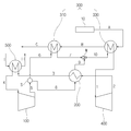
도 1은 본 발명의 일 실시 예에 따른 폐열 회수 발전 시스템을 도시한 모식도이고, 도 2는 도 1의 폐열 회수 발전 시스템에 따른 추가 구성을 도시한 모식도이다.FIG. 1 is a schematic diagram showing a waste heat recovery power generation system according to an embodiment of the present invention, and FIG. 2 is a schematic diagram showing a further configuration according to the waste heat recovery power generation system of FIG.
도 1 및 도 2에 도시된 바와 같이, 본 발명의 일 실시 예에 따른 초임계 이산화탄소 발전 시스템은 이산화탄소를 작동 유체로 사용하며, 작동 유체를 압축시키는 압축기(100)와, 압축기(100)를 통과한 작동 유체와 열교환하는 리큐퍼레이터(200) 및 복수의 열원(300)과, 리큐퍼레이터(200) 및 열원(300)을 통과하며 가열된 작동 유체에 의해 구동되는 터빈(400)과, 터빈(400)에 의해 구동되는 발전기(450), 그리고 압축기(100)로 유입되는 작동 유체를 냉각시키는 쿨러(500)를 포함하여 구성될 수 있다.1 and 2, a supercritical carbon dioxide power generation system according to an embodiment of the present invention includes a
본 발명의 각 구성들은 작동 유체가 흐르는 이송관(도 1 내지 4의 stream 1 내지 12)에 의해 연결되며, 특별히 언급하지 않더라도 작동 유체는 이송관을 따라 유동하는 것으로 이해되어야 한다. 다만, 복수 개의 구성들이 일체화 되어 있는 경우, 일체화된 구성 내에 사실상 이송관의 역할을 하는 부품 내지 영역이 있을 것이므로, 이 경우에도 당연히 작동 유체는 이송관을 따라 유동하는 것으로 이해되어야 한다. 별도의 기능을 하는 유로의 경우 추가로 설명하기로 한다.Each configuration of the present invention is connected by a transfer tube (
압축기(100)는 후술할 터빈(400)에 의해 구동되며, 쿨러(500)를 거쳐(stream 4) 냉각된 저온의 작동 유체를 리큐퍼레이터(200)로 보내는 역할을 한다(stream 5, 8). 압축기(100)의 후단에는 압축기(100)를 통과한 작동 유체의 유량을 분배하기 위한 세퍼레이터(S)가 구비된다.The
세퍼레이터(S)는 압축기(100)를 통과한 유량을 후술할 열원(300) 중 하나와 후술할 리큐퍼레이터(200)로 분기하는 역할을 한다(stream 6, 8). 발전 시스템에서 가장 저온인 압축기(100) 후단에서 작동 유체의 유량 일부를 분기해 폐열을 회수하는 열원(300)으로 보내(stream 6) 열교환에 사용함으로써 폐열 흡수량을 최대한 유지할 수 있다(작동 유체의 유량 분배 및 유량 제어에 관해서는 후술하기로 함).The separator S serves to branch the flow rate of the refrigerant passing through the
리큐퍼레이터(200)는 터빈(400)을 통과해 팽창되면서 고온에서 중온으로 냉각된 작동 유체와(stream 2) 후술할 압축기(100)를 거쳐 리큐퍼레이터(200)를 통과하는 작동 유체(stream 8)를 열교환하는 역할을 한다. 리큐퍼레이터(200)는 세퍼레이터(S)에 의해 분기된 이송관 상에 설치되되, 터빈(400)의 배출단과 쿨러(500)의 유입단 사이(stream 3)에 배치된다. 리큐퍼레이터(200)에서 압축기(100)를 거친 작동 유체는 터빈(400)을 통과한 작동 유체에 의해 1차로 가열된다. The
리큐퍼레이터(200)에서 열교환에 의해 1차로 냉각된 작동 유체는 쿨러(500)로 보내져 2차로 냉각된 후(stream 3) 압축기(100)로 보내진다(stream 4). 리큐퍼레이터(200)에서 열교환에 의해 1차로 가열된 작동 유체는 후술할 열원(300)으로 공급된다. The working fluid, which is firstly cooled by the heat exchange in the
열원(300)은 배출되는 기체의 배출 조건이 정해져 있는 제한 열원(constrained heat source)과 배출되는 기체의 배출 조건이 정해져 있지 않은 일반 열원으로 구성될 수 있다. 본 명세서에서는 편의상 제1 열교환기(310)가 제한 열원으로 구성되고, 제2 열교환기(330)가 일반 열원으로 구성된 것을 예로 하여 설명한다. The
제2 열교환기(330)는 폐열원(10)에 가까운 쪽에 배치되고, 제1 열교환기(310)는 폐열원으로부터 제2 열교환기(330)에 비해 상대적으로 먼 쪽에 배치된다.The
제1 열교환기(310)는 타 발전 사이클의 배기 가스와 같이 폐열을 갖는 기체(이하 폐열 기체)를 열원으로 사용하되, 폐열 기체의 배출 시(C) 배출 규제 조건을 갖는 열원이다. 배출 규제 조건은 온도 조건이며, 제1 열교환기(310)로 유입되는 폐열 기체의 온도는 후술할 제2 열교환기(330)로 유입되는 폐열 기체의 온도보다 상대적으로 낮다. 이는 폐열원과의 거리가 상대적으로 멀기 때문이다. The
제1 열교환기(310)는 폐열 기체의 열로 압축기(100)를 통과해 제1 열교환기(310)로 유입되는(stream 6) 작동 유체를 가열한다. 제1 열교환기(310)에서 열을 빼앗긴 폐열 기체는 배출 규제 조건에 맞는 온도로 냉각되어 제1 열교환기(310)를 빠져나간다(C). 제1 열교환기(310)로 냉각 유체의 유량을 얼만큼 보내느냐에 따라 폐열을 흡수할 수 있는 정도가 달라진다. 제1 열교환기(310)를 통과해 가열된 작동 유체는 리큐퍼레이터(200)의 후단에서 리큐퍼레이터(200)를 통과해 1차로 가열된 작동 유체와 혼합되어(stream 7) 제1 열교환기(310)로 공급된다(stream 10).The
제2 열교환기(330)는 폐열 기체와 작동 유체를 열교환하여 작동 유체를 가열하는 역할을 하며, 배출 규제 조건이 없는 열원이다. 제2 열교환기(330)로 유입(A)되는 폐열 기체의 온도는 제1 열교환기(310)로 유입되는 폐열 기체의 온도보다 상대적으로 높다. 이는 제2 열교환기(330)가 폐열원과 상대적으로 가까운 거리에 배치되기 때문이다.The
제2 열교환기(330)로는 리큐퍼레이터(200)를 통과한 작동 유체 및 제1 열교환기(310)에서 가열된 작동 유체가 혼합된 작동 유체의 유량이 유입된다. 작동 유체의 혼합을 위해 제1 열교환기(310)와 제2 열교환기(330)의 사이에는 믹서(M)가 설치된다. 믹서(M)는 9번 stream과 10번 stream의 합류점에 구비된다. 제2 열교환기(330)는 이 혼합된 유량의 작동 유체를 가열한다. 제2 열교환기(330)에서 가열된 작동 유체는 터빈(400)으로 공급된다(stream 1).The
제2 열교환기(330)로 유입되는 유량이 최초 압축기(100)의 후단에서 분기된 두 개의 스트림(stream)이 다시 더해진 유량이므로, 발전 시스템 전체의 유량이 제2 열교환기(330)로 유입되는 셈이다. 따라서 터빈(400)으로 유입되는 유량은 전체 유량에 해당하며, 압축기(100) 후단에서 작동 유체의 유량을 분기하더라도 터빈(400)으로 유입되는 전체 유량은 변하지 않고 동일하게 유지될 수 있다.The flow rate of the entire power generation system is supplied to the
터빈(400)은 작동 유체에 의해 구동되며, 발전기(450)를 구동시킴으로써 전력을 생산하는 역할을 한다. 터빈(400)을 통과하면서 작동 유체가 팽창되므로 터빈(400)은 팽창기(expander)의 역할도 하게 된다.The
또한, 도 2에 도시된 바와 같이, 터빈(400)과 압축기(100)의 속도를 동일하게 설계하면 터빈(400)과 압축기(100)를 동축으로 설계하여 터빈(400)이 발전기(450) 및 압축기(100)를 동시에 구동시킬 수 있다. 이때, 터빈(400)은 발전기(450)의 출력 주파수에 대응하는 회전수로 회전해야 하나 압축기(100)와 동축 설계 시 발전기(450)의 출력 주파수에 대응하는 회전수로 회전할 수 없다. 따라서 터빈(400)과 발전기(450)의 사이에 기어 박스나 토크 컨버터() 등을 구비함으로써 터빈(400)의 출력을 발전기(450)의 출력 주파수에 대응하도록 변환하여 공급할 수 있다.2, if the speeds of the
전술한 구성을 갖는 본 발명의 일 실시 예에 따른 폐열 회수 발전 시스템에 있어서, 작동 유체의 유량을 제어하여 폐열원의 온도 및 유량 변화에 대응하는 방법에 대해 설명하기로 한다.In the waste heat recovery power generation system according to the embodiment of the present invention having the above-described configuration, a method of controlling the flow rate of the working fluid to cope with the change in temperature and flow rate of the waste heat source will be described.
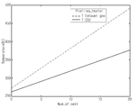
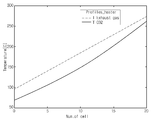
도 3은 도 1의 폐열 회수 발전 시스템에 따른 세부 구성을 도시한 모식도이다. 도 4는 도 1의 폐열 회수 발전 시스템에 따른 터빈 입구 온도와 시스템 출력의 일 예를 도시한 그래프이고, 도 5는 도 1의 폐열 회수 발전 시스템에 따른 고온측 폐열 회수 히터에서의 온도 분포를 나타난 그래프이며, 도 6은 도 1의 폐열 회수 발전 시스템에 따른 저온측 폐열 회수 히터에서의 온도 분포를 나타낸 그래프이다.3 is a schematic diagram showing a detailed configuration according to the waste heat recovery power generation system of FIG. FIG. 4 is a graph showing an example of a turbine inlet temperature and a system output according to the waste heat recovery power generation system of FIG. 1, and FIG. 5 is a graph showing a temperature distribution in a high temperature side waste heat recovery heater according to the waste heat recovery power generation system of FIG. And FIG. 6 is a graph showing a temperature distribution in a low-temperature-side waste heat recovery heater according to the waste heat recovery power generation system of FIG.
먼저 도 3에 도시된 바와 같이, 본 발명의 일 실시 예에 따른 폐열 회수 발전 시스템은 압축기(100)의 입구(4번 stream)와, 저온측 열원인 제1 열교환기(310)의 유입단(6번 stream)에 유량을 측정하기 위한 유량 측정기를 각각 설치할 수 있다.3, the waste heat recovery power generation system according to an embodiment of the present invention includes an inlet (stream 4) of the
또한, 저온측 제1 열교환기(310)와 고온측 제2 열교환기(330)의 사이 중 믹서(M)의 전단(7번 stream), 그리고 세퍼레이터(S)와 리큐퍼레이터(200)의 사이(8번 stream)에는 유량 조절 밸브가 설치될 수 있다.It is also preferable that the front end (stream 7) of the mixer M between the low temperature side
7번 stream에 설치되는 유량 조절 밸브는 열원의 최종 출구(C stream)의 온도를 측정해 그 결과에 따라 열흡수가 최대가 되도록 개폐된다. 즉, C stream의 온도가 배출 규제 조건의 온도 보다 높으면 7번 stream의 유량 조절 밸브가 개방되도록 제어되어 제1 열교환기(310)로 이송되는 작동 유체의 유량을 증가시킴으로써 C stream의 온도를 낮춰준다. 반대로 C stream의 온도가 배출 규제 조건의 온도 보다 낮으면 유량 조절 밸브가 폐쇄되도록 제어되어 제1 열교환기(310)로 이송되는 작동 유체를 차단함으로써 C stream의 온도를 일정하게 유지해준다. 이러한 과정에 의해 C stream의 온도를 일정하게 유지할 수 있다.The flow control valve installed in
또한, 유량 조절 밸브가 7번 stream에 설치됨으로써 밸브의 압력을 조절해 리큐퍼레이터(200)에서 믹서(M)를 향하는 9번 stream의 작동 유체가 7번 stream으로 역류되는 것을 방지할 수 있다.Also, since the flow control valve is installed in the
한편, 열원에서 공급되는 열량이 늘어나 시스템 전체의 유량 증가가 필요한 경우가 발생할 수 있다. On the other hand, the amount of heat supplied from the heat source is increased, so that it may be necessary to increase the flow rate of the entire system.
이 경우에는 4번과 6번 stream의 작동 유체의 유량을 측정한 후 7번 stream의 유량 조절 밸브는 C stream의 온도를 일정하게 유지하도록 한다. 동시에 8번 stream에 설치된 유량 조절 밸브를 열어 전체 발전 시스템의 유량을 증가시킬 수 있다. 부족한 작동 유체의 유량은 별도의 작동 유체 저장 탱크()를 구비하고, 저장 탱크로부터 부족한 유량만큼 발전 시스템 내로 작동 유체를 공급하게 된다.In this case, after measuring the flow rate of the working fluid in
반대로 열원에서 공급되는 열량이 부족하여 시스템 전체의 유량 감소가 필요한 경우가 발생할 수 있다.Conversely, there may be a case where the amount of heat supplied from the heat source is insufficient to reduce the flow rate of the entire system.
이 경우에는 6번 stream의 작동 유체의 유량을 측정한 후 7번 stream의 유량 조절 밸브는 C stream의 온도를 일정하게 유지하도록 한다. 동시에 8번 stream에 설치된 유량 조절 밸브를 닫아 전체 발전 시스템의 유량을 감소시킬 수 있다. 이를 위해 터빈(400)의 입구와 출구 사이에 바이패스 밸브()가 구비되고, 바이패스 밸브()는 별도의 이송관을 통해 저장 탱크()와 연결되는 것이 바람직하다. 바이패스 밸브()가 작동되면 제2 열교환기(330)를 거친 작동 유체가 터빈(400) 쪽으로 보내지지 않고 별도의 이송관()을 통해 저장 탱크()로 회수된다.In this case, after measuring the flow rate of the working fluid in
전술한 작동 유체의 유량 조절과 관련하여, 압축기(100) 입구의 온도를 일정하게 유지하기 위해 쿨러(500)의 유량을 조절할 수도 있다.The flow rate of the cooler 500 may be adjusted in order to keep the temperature of the inlet of the
전술한 유량 조절 방법에 따라 작동 유체의 유량을 조절함에 있어, 시스템의 출력과 온도 관계를 간단히 설명하면 다음과 같다.The following is a brief description of the relationship between the output and the temperature of the system in adjusting the flow rate of the working fluid according to the flow rate control method described above.
도 4에 도시된 바와 같이, 시스템에 주어지는 열량이 일정하면(C stream의 온도가 일정하게 유지될 때), 시스템의 설계 시 전체 유량이 증가할 때 터빈(400) 입구의 온도가 낮아지고, 전체 유량이 감소할 때 터빈(400) 입구의 온도가 높아진다. 이러한 상관 관계에 따라 전체 시스템이 낼 수 있는 최대 출력은 열원의 특성에 따라 다르기는 하지만 최적의 설계점이 존재하게 된다(예를 들어, 열원의 온도가 섭씨 490도라면 약 섭씨 370도 전후로 최적 설계점이 됨).As shown in FIG. 4, when the amount of heat given to the system is constant (when the temperature of the C stream is kept constant), the temperature of the inlet of the
일반적으로 터빈(400) 입구의 온도가 높아지면 시스템 전체의 출력이 증가하지만, 초임계 이산화탄소 발전 사이클의 특성 상 터빈(400) 입구의 온도가 낮더라도 유량을 증가시키는 것이 시스템의 출력 증가에 유리한 최적 설계점이 있다.Generally, when the temperature of the inlet of the
열원의 특성에 따라 다르기는 하나, 예를 들어 제2 열교환기(330)에서 폐열 기체와 작동 유체의 온도 차이는 도 5에 도시된 바와 같은 분포를 보일 수 있으며, 제1 열교환기(310)에서 폐열 기체와 작동 유체의 온도 차이는 도 6에 도시된 바와 같은 분포를 보일 수 있다.For example, in the
이러한 상관관계를 고려할 때, 본 발명은 제1 열교환기(310)와 제2 열교환기(330) 사이의 작동 유체의 온도가 작아질수록 시스템의 전체 효율을 증가시킬 수 있다. 예를 들어, 본 발명에서는 약 10도의 온도 차이를 갖는 것이 최적 설계점이 될 수 있다.In consideration of this correlation, the present invention can increase the overall efficiency of the system as the temperature of the working fluid between the
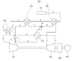
이상에서는 한 개의 리큐퍼레이터를 활용한 발전 시스템에 대해 설명하였으며, 이하에서는 복수의 리큐퍼레이터를 활용한 발전 시스템에 대해 설명하기로 한다(편의상 전술한 실시 예와 동일한 구성에 대해서는 상세한 설명을 생략하기로 한다).도 7은 본 발명의 다른 실시 예에 따른 폐열 회수 발전 시스템을 도시한 모식도이다.A power generation system utilizing one recuperator has been described. Hereinafter, a power generation system utilizing a plurality of recuperators will be described (for the sake of convenience, a detailed description of the same configuration as the above embodiment will be omitted 7 is a schematic diagram showing a waste heat recovery power generation system according to another embodiment of the present invention.
도 7에 도시된 바와 같이, 본 발명의 다른 실시 예에 따른 폐열 회수 발전 시스템은 압축기(100a) 후단의 세퍼레이터(S)를 통해 분기된 유량이 유입되는 제1 리큐퍼레이터(200a)와, 제1 리큐퍼레이터(200a)를 통과한 유량이 유입되는 제2 리큐퍼레이터(200b)를 구비할 수 있다.7, the waste heat recovery power generation system according to another embodiment of the present invention includes a
압축기(100a)를 통과한 작동 유체는 세퍼레이터(S)에서 분기되어 제1 열교환기(310a) 또는 제1 리큐퍼레이터(200a)로 보내진다.The working fluid that has passed through the
제1 열교환기(310a)로 보내진(7번 stream) 작동 유체는 폐열 기체와 열교환해 1차로 가열된 뒤 믹서(M)로 공급되고(8번 stream), 제1 리큐퍼레이터(200a)로 보내진(9번 stream) 작동 유체는 터빈(400a) 및 제2 리큐퍼레이터(200b)를 통과한 작동 유체와 열교환해 1차로 가열된 뒤 제2 리큐퍼레이터(200b)로 보내진다(10번 stream). 제2 리큐퍼레이터(200b)에서 2차로 가열된 작동 유체는 믹서(M)로 보내진다(11번 stream). 믹서(M)에서 8번 및 11번 stream의 작동 유체가 혼합된 뒤 제2 열교환기(330a)로 보내지고(12번 stream), 제2 열교환기(330a)에서 폐열 기체와 열교환해 가열된 고온의 작동 유체는 터빈(400a)으로 공급된다.The working fluid (stream 7) sent to the
터빈(400a)을 통과하며 팽창 및 중온 상태가 된 작동 유체는 제2 리큐퍼레이터(200b) 및 제1 리큐퍼레이터(200a)를 순차적으로 거치면서 1차로 냉각된다(2번 및 3번 stream). 냉각된 작동 유체는 쿨러(500)로 보내져(4번 stream) 저온으로 냉각된 뒤 다시 압축기(100a)로 공급된다.The working fluid which has passed through the
이와 같이, 터빈(400a)을 통과한 작동 유체가 제2 리큐퍼레이터(200b)를 먼저 거치므로 제2 리큐퍼레이터(200b)는 고온측 복열기가 되며, 제1 리큐퍼레이터(200a)는 저온측 복열기가 된다.Since the working fluid that has passed through the
이렇게 복수의 리큐퍼레이터를 적용하는 경우, 고온측과 저온측 복열기에 각기 다른 소재를 사용할 수 있어 제작 단가가 감소되는 효과가 있다.When a plurality of recupillators are applied in this way, different materials can be used for the high-temperature side and the low-temperature side heat exchanger, thereby reducing the manufacturing cost.
전술한 바와 같이, 본 발명의 실시 예들에 따른 폐열 회수 발전 시스템은 압축기 후단에서 분기되는 작동 유체의 분기량을 조절하여 폐열 회수 히터의 열교환량을 조절함으로써 전체 시스템의 유량 변경 없이 폐열원의 온도와 유량 변동에 대응할 수 있다. 이에 따라 시스템을 설계점 근처에서 운전 가능하므로 전체 발전 시스템의 성능을 일정하게 유지할 수 있다.As described above, the waste heat recovery power generation system according to the embodiments of the present invention adjusts the amount of the working fluid branched from the rear end of the compressor to adjust the heat exchange amount of the waste heat recovery heater, thereby changing the temperature of the waste heat source It is possible to cope with the flow rate fluctuation. As a result, the system can be operated near the design point, so that the performance of the entire power generation system can be kept constant.
앞에서 설명되고 도면에 도시된 본 발명의 일 실시 예는, 본 발명의 기술적 사상을 한정하는 것으로 해석되어서는 안 된다. 본 발명의 권리범위는 청구범위에 기재된 사항에 의해서만 제한되고, 본 발명의 기술분야에서 통상의 지식을 가진 자는 본 발명의 기술적 사상을 다양한 형태로 개량 및 변경하는 것이 가능하다. 따라서 이러한 개량 및 변경이 통상의 지식을 가진 자에게 자명한 것인 한, 본 발명의 권리범위에 속하게 될 것이다.One embodiment of the present invention described above and shown in the drawings should not be construed as limiting the technical spirit of the present invention. The scope of the present invention is limited only by the matters described in the claims, and those skilled in the art can improve and modify the technical spirit of the present invention in various forms. Accordingly, it is intended that the present invention cover the modifications and variations of this invention provided they come within the scope of the appended claims and their equivalents.
100: 압축기
200, 200a, 200b: 리큐퍼레이터
310: 제1 열교환기
330: 제2 열교환기
400: 터빈
450: 발전기
500: 쿨러100:
310: first heat exchanger 330: second heat exchanger
400: turbine 450: generator
500: Cooler
Claims (17)
폐열원에서 공급되는 폐열 기체로부터 폐열을 회수하여 상기 작동 유체를 가열하는 복수의 열교환기와,
상기 열교환기를 통과해 가열된 상기 작동 유체에 의해 구동되는 터빈과,
상기 터빈을 통과한 상기 작동 유체와 상기 압축기를 통과한 상기 작동 유체를 열교환하여 상기 터빈을 통과한 상기 작동 유체를 냉각시키는 리큐퍼레이터를 포함하며,
상기 압축기의 후단에서 상기 압축기를 통과한 상기 작동 유체의 유량이 분기되는 것을 특징으로 하는 폐열 회수 발전 시스템.A compressor for compressing the working fluid;
A plurality of heat exchangers for recovering waste heat from a waste heat source supplied from a waste heat source to heat the working fluid,
A turbine driven by the working fluid heated through the heat exchanger,
And a recuperator that cools the working fluid that has passed through the turbine by exchanging heat between the working fluid that has passed through the turbine and the working fluid that has passed through the compressor,
Wherein the flow rate of the working fluid that has passed through the compressor at the rear end of the compressor is branched.
상기 압축기의 후단에서 분기된 상기 작동 유체의 유량은 상기 리큐퍼레이터와 상기 열원으로 각각 공급되는 것을 특징으로 하는 폐열 회수 발전 시스템.The method according to claim 1,
Wherein the flow rate of the working fluid branched at the rear end of the compressor is supplied to the recuperator and the heat source, respectively.
상기 열교환기는 제1 열교환기 및 제2 열교환기를 포함하고, 상기 제1 열교환기는 상기 폐열 기체가 배출되는 배출단 쪽인 저온측에 구비되고, 상기 제2 열교환기는 상기 폐열 기체가 유입되는 유입단 쪽인 고온측에 구비되는 것을 특징으로 하는 폐열 회수 발전 시스템.3. The method of claim 2,
Wherein the heat exchanger includes a first heat exchanger and a second heat exchanger, wherein the first heat exchanger is provided at a low temperature side which is a discharge end side from which the waste heat gas is discharged, and the second heat exchanger has a high temperature Side heat recovery power generation system.
상기 압축기의 후단에서 분기되어 상기 리큐퍼레이터를 거친 상기 작동 유체는 상기 제2 열교환기로 이송되는 것을 특징으로 하는 폐열 회수 발전 시스템.The method of claim 3,
And the working fluid branched from the rear end of the compressor and passed through the recuperator is transferred to the second heat exchanger.
상기 압축기의 후단에서 분기된 상기 작동 유체의 유량은 상기 제1 열교환기로 이송되는 것을 특징으로 하는 폐열 회수 발전 시스템.5. The method of claim 4,
And the flow rate of the working fluid branched at the rear end of the compressor is transferred to the first heat exchanger.
상기 제1 열교환기를 통과해 가열된 상기 작동 유체의 유량은 상기 제2 열교환기의 전단에서 상기 리큐퍼레이터를 통과한 상기 작동 유체의 유량과 합쳐지는 것을 특징으로 하는 폐열 회수 발전 시스템.6. The method of claim 5,
Wherein the flow rate of the working fluid heated through the first heat exchanger is combined with the flow rate of the working fluid passing through the recuperator at the front end of the second heat exchanger.
상기 작동 유체의 유량 혼합을 위해 상기 제2 열교환기의 전단에 구비되는 믹서와, 상기 작동 유체의 유량 분기를 위해 상기 압축기의 후단에 구비되는 세퍼레이터를 더 포함하는 폐열 회수 발전 시스템.The method according to claim 6,
A mixer provided at a front end of the second heat exchanger for mixing the working fluid; and a separator provided at a rear end of the compressor for branching the flow of the working fluid.
상기 터빈에 연결되어 전력을 발생시키는 발전기와, 상기 터빈과 상기 발전기의 사이에 구비되어 상기 터빈의 출력을 상기 발전기의 출력 주파수에 대응하도록 전환하여 상기 발전기에 전달하는 기어박스를 더 포함하고, 상기 터빈과 상기 압축기는 동축으로 연결되어 상기 터빈에 의해 상기 압축기 및 발전기가 구동되는 것을 특징으로 하는 폐열 회수 발전 시스템.The method according to claim 1,
Further comprising a gear box disposed between the turbine and the generator for switching the output of the turbine to correspond to an output frequency of the generator and transmitting the converted output to the generator, Wherein the turbine and the compressor are coaxially connected and the compressor and the generator are driven by the turbine.
폐열원에서 공급되는 폐열 기체로부터 폐열을 회수하여 상기 작동 유체를 가열하는 복수의 열교환기와,
상기 열교환기를 통과해 가열된 상기 작동 유체에 의해 구동되는 터빈과,
상기 터빈을 통과한 상기 작동 유체와 상기 압축기를 통과한 상기 작동 유체를 열교환하여 상기 터빈을 통과한 상기 작동 유체를 냉각시키는 복수의 리큐퍼레이터를 포함하며,
상기 압축기의 후단에서 상기 압축기를 통과한 상기 작동 유체의 유량이 분기되는 것을 특징으로 하는 폐열 회수 발전 시스템.A compressor for compressing the working fluid;
A plurality of heat exchangers for recovering waste heat from a waste heat source supplied from a waste heat source to heat the working fluid,
A turbine driven by the working fluid heated through the heat exchanger,
And a plurality of recupilators for exchanging heat between the working fluid that has passed through the turbine and the working fluid that has passed through the compressor to cool the working fluid that has passed through the turbine,
Wherein the flow rate of the working fluid that has passed through the compressor from the rear end of the compressor is branched.
상기 압축기의 후단에서 분기된 상기 작동 유체의 유량은 상기 리큐퍼레이터와 상기 열원으로 각각 공급되는 것을 특징으로 하는 폐열 회수 발전 시스템.10. The method of claim 9,
Wherein the flow rate of the working fluid branched at the rear end of the compressor is supplied to the recuperator and the heat source, respectively.
상기 열교환기는 제1 열교환기 및 제2 열교환기를 포함하고, 상기 제1 열교환기는 상기 폐열 기체가 배출되는 배출단 쪽인 저온측에 구비되고, 상기 제2 열교환기는 상기 폐열 기체가 유입되는 유입단 쪽인 고온측에 구비되는 것을 특징으로 하는 폐열 회수 발전 시스템.11. The method of claim 10,
Wherein the heat exchanger includes a first heat exchanger and a second heat exchanger, wherein the first heat exchanger is provided at a low temperature side which is a discharge end side from which the waste heat gas is discharged, and the second heat exchanger has a high temperature Side heat recovery power generation system.
상기 리큐퍼레이터는 제1 리큐퍼레이터 및 제2 리큐퍼레이터를 포함하고, 상기 제2 리큐퍼레이터는 상기 터빈을 통과한 상기 작동 유체가 유입되는 고온측 복열기, 상기 제1 리큐퍼레이터는 상기 제2 리큐퍼레이터를 통과한 상기 작동 유체가 유입되는 저온측 복열기인 것을 특징으로 하는 폐열 회수 발전 시스템.12. The method of claim 11,
Wherein the recuperator includes a first recuperator and a second recuperator, the second recuperator includes a high temperature side recuperator through which the working fluid that has passed through the turbine flows, a first recuperator Wherein the working fluid passing through the second recuperator is a low-temperature-side recuperator.
상기 압축기 후단에서 분기되어 상기 제1 리큐퍼레이터로 보내진 상기 작동 유체는 상기 제2 리큐퍼레이터를 거쳐 상기 제2 열교환기로 이송되는 것을 특징으로 하는 폐열 회수 발전 시스템.13. The method of claim 12,
And the working fluid branched from the rear end of the compressor and sent to the first recuperator is transferred to the second heat exchanger through the second recuperator.
상기 압축기 후단에서 분기된 상기 작동 유체의 유량은 상기 제1 열교환기로 이송되는 것을 특징으로 하는 폐열 회수 발전 시스템.14. The method of claim 13,
Wherein the flow rate of the working fluid branched at the rear end of the compressor is transferred to the first heat exchanger.
상기 제1 열교환기를 통과해 가열된 상기 작동 유체의 유량은 상기 제2 열교환기의 전단에서 상기 제2 리큐퍼레이터를 통과한 상기 작동 유체의 유량과 합쳐지는 것을 특징으로 하는 폐열 회수 발전 시스템.15. The method of claim 14,
Wherein the flow rate of the working fluid heated through the first heat exchanger is combined with the flow rate of the working fluid passing through the second recuperator at the front end of the second heat exchanger.
상기 작동 유체의 유량 혼합을 위해 상기 제2 열교환기의 전단에 구비되는 믹서와, 상기 작동 유체의 유량 분기를 위해 상기 압축기의 후단에 구비되는 세퍼레이터를 더 포함하는 폐열 회수 발전 시스템.16. The method of claim 15,
A mixer provided at a front end of the second heat exchanger for mixing the working fluid; and a separator provided at a rear end of the compressor for branching the flow of the working fluid.
상기 터빈에 연결되어 전력을 발생시키는 발전기와, 상기 터빈과 상기 발전기의 사이에 구비되어 상기 터빈의 출력을 상기 발전기의 출력 주파수에 대응하도록 전환하여 상기 발전기에 전달하는 기어박스를 더 포함하고, 상기 터빈과 상기 압축기는 동축으로 연결되어 상기 터빈에 의해 상기 압축기 및 발전기가 구동되는 것을 특징으로 하는 폐열 회수 발전 시스템.10. The method of claim 9,
Further comprising a gear box disposed between the turbine and the generator for switching the output of the turbine to correspond to an output frequency of the generator and transmitting the converted output to the generator, Wherein the turbine and the compressor are coaxially connected and the compressor and the generator are driven by the turbine.
Priority Applications (3)
| Application Number | Priority Date | Filing Date | Title |
|---|---|---|---|
| KR1020160015475A KR20170094580A (en) | 2016-02-11 | 2016-02-11 | Waste Heat Recovery Power Generation System |
| PCT/KR2016/003938 WO2017138677A1 (en) | 2016-02-11 | 2016-04-15 | Waste heat recovery power generation system and flow control method for power generation system |
| US15/177,790 US10907509B2 (en) | 2016-02-11 | 2016-06-09 | Waste heat recovery power generation system and flow control method thereof |
Applications Claiming Priority (1)
| Application Number | Priority Date | Filing Date | Title |
|---|---|---|---|
| KR1020160015475A KR20170094580A (en) | 2016-02-11 | 2016-02-11 | Waste Heat Recovery Power Generation System |
Publications (1)
| Publication Number | Publication Date |
|---|---|
| KR20170094580A true KR20170094580A (en) | 2017-08-21 |
Family
ID=59757511
Family Applications (1)
| Application Number | Title | Priority Date | Filing Date |
|---|---|---|---|
| KR1020160015475A KR20170094580A (en) | 2016-02-11 | 2016-02-11 | Waste Heat Recovery Power Generation System |
Country Status (1)
| Country | Link |
|---|---|
| KR (1) | KR20170094580A (en) |
Cited By (2)
| Publication number | Priority date | Publication date | Assignee | Title |
|---|---|---|---|---|
| KR20190046105A (en) * | 2017-10-25 | 2019-05-07 | 두산중공업 주식회사 | Supercritical CO2 Power generation plant |
| KR20190057971A (en) * | 2017-11-21 | 2019-05-29 | 두산중공업 주식회사 | Hybrid power generation system using a supercritical CO2 working fluid |
-
2016
- 2016-02-11 KR KR1020160015475A patent/KR20170094580A/en active Search and Examination
Cited By (2)
| Publication number | Priority date | Publication date | Assignee | Title |
|---|---|---|---|---|
| KR20190046105A (en) * | 2017-10-25 | 2019-05-07 | 두산중공업 주식회사 | Supercritical CO2 Power generation plant |
| KR20190057971A (en) * | 2017-11-21 | 2019-05-29 | 두산중공업 주식회사 | Hybrid power generation system using a supercritical CO2 working fluid |
Similar Documents
| Publication | Publication Date | Title |
|---|---|---|
| US10907509B2 (en) | Waste heat recovery power generation system and flow control method thereof | |
| US10371015B2 (en) | Supercritical CO2 generation system for parallel recuperative type | |
| KR101719234B1 (en) | Supercritical CO2 generation system | |
| KR101800081B1 (en) | Supercritical CO2 generation system applying plural heat sources | |
| KR101638287B1 (en) | Supercritical CO2 generation system | |
| US10309262B2 (en) | Complex supercritical CO2 generation system | |
| KR101674804B1 (en) | Supercritical CO2 generation system | |
| EP2369145A1 (en) | Power generation system and method | |
| KR20190010038A (en) | Hybrid power generating system | |
| KR101898324B1 (en) | Waste Heat Recovery Power Generation System and flow control method, and management method thereof | |
| KR101628611B1 (en) | Supercritical CO2 generation system using multistage compressing and expanding of working fluid | |
| US10287926B2 (en) | Supercritical CO2 generation system applying recuperator per each heat source | |
| KR20170094580A (en) | Waste Heat Recovery Power Generation System | |
| US10526925B2 (en) | Supercritical CO2 generation system for series recuperative type | |
| JP6582316B2 (en) | Sealing gas supply device | |
| KR101864983B1 (en) | Supercritical CO2 power generating system | |
| KR101812919B1 (en) | Complex supercritical CO2 generation system | |
| US10202874B2 (en) | Supercritical CO2 generation system applying plural heat sources | |
| KR101939436B1 (en) | Supercritical CO2 generation system applying plural heat sources | |
| KR101822328B1 (en) | Complex supercritical CO2 generation system | |
| KR101628619B1 (en) | generation system having temperature control device for heat exchanger | |
| KR101797435B1 (en) | Supercritical CO2 generation system applying recuperator per each heat source | |
| KR101638286B1 (en) | Supercritical CO2 generation system and method for controlling output thereof | |
| KR101939029B1 (en) | Supercritical CO2 generation system applying plural heat sources | |
| KR102083867B1 (en) | Power generating system for supercritical CO2 |
Legal Events
| Date | Code | Title | Description |
|---|---|---|---|
| A201 | Request for examination | ||
| E902 | Notification of reason for refusal | ||
| AMND | Amendment | ||
| E601 | Decision to refuse application | ||
| AMND | Amendment | ||
| J201 | Request for trial against refusal decision | ||
| J301 | Trial decision |
Free format text: TRIAL NUMBER: 2018101003959; TRIAL DECISION FOR APPEAL AGAINST DECISION TO DECLINE REFUSAL REQUESTED 20180921 Effective date: 20191219 |