KR20170094364A - Method for manufacturing tooth-shaped component, and tooth-shaped component - Google Patents
Method for manufacturing tooth-shaped component, and tooth-shaped component Download PDFInfo
- Publication number
- KR20170094364A KR20170094364A KR1020177019162A KR20177019162A KR20170094364A KR 20170094364 A KR20170094364 A KR 20170094364A KR 1020177019162 A KR1020177019162 A KR 1020177019162A KR 20177019162 A KR20177019162 A KR 20177019162A KR 20170094364 A KR20170094364 A KR 20170094364A
- Authority
- KR
- South Korea
- Prior art keywords
- punch
- die
- tooth
- toothed
- coarse
- Prior art date
Links
- 238000000034 method Methods 0.000 title claims abstract description 278
- 238000004519 manufacturing process Methods 0.000 title claims abstract description 211
- 230000008569 process Effects 0.000 claims abstract description 238
- 239000000463 material Substances 0.000 claims abstract description 140
- 230000009467 reduction Effects 0.000 claims abstract description 60
- 238000000465 moulding Methods 0.000 claims description 130
- 238000007493 shaping process Methods 0.000 claims description 97
- 238000011946 reduction process Methods 0.000 claims description 60
- 238000005520 cutting process Methods 0.000 claims description 20
- 230000002787 reinforcement Effects 0.000 claims description 15
- 210000000988 bone and bone Anatomy 0.000 claims description 9
- 238000003754 machining Methods 0.000 claims description 8
- 206010042496 Sunburn Diseases 0.000 claims description 2
- 238000007788 roughening Methods 0.000 claims description 2
- 238000004080 punching Methods 0.000 claims 1
- 230000003014 reinforcing effect Effects 0.000 description 34
- 238000010273 cold forging Methods 0.000 description 25
- 230000008602 contraction Effects 0.000 description 25
- 229910052751 metal Inorganic materials 0.000 description 18
- 239000002184 metal Substances 0.000 description 18
- 230000002093 peripheral effect Effects 0.000 description 17
- 210000004210 tooth component Anatomy 0.000 description 13
- 238000005242 forging Methods 0.000 description 8
- 238000010586 diagram Methods 0.000 description 7
- 229910000831 Steel Inorganic materials 0.000 description 6
- 239000010959 steel Substances 0.000 description 6
- 238000007796 conventional method Methods 0.000 description 5
- 230000000630 rising effect Effects 0.000 description 4
- 230000008719 thickening Effects 0.000 description 4
- 230000005540 biological transmission Effects 0.000 description 3
- 230000002706 hydrostatic effect Effects 0.000 description 3
- XEEYBQQBJWHFJM-UHFFFAOYSA-N Iron Chemical compound [Fe] XEEYBQQBJWHFJM-UHFFFAOYSA-N 0.000 description 2
- 239000011324 bead Substances 0.000 description 2
- 230000008901 benefit Effects 0.000 description 2
- 239000002131 composite material Substances 0.000 description 2
- 238000000748 compression moulding Methods 0.000 description 2
- 230000007246 mechanism Effects 0.000 description 2
- 210000003205 muscle Anatomy 0.000 description 2
- 238000003825 pressing Methods 0.000 description 2
- 239000000758 substrate Substances 0.000 description 2
- RYGMFSIKBFXOCR-UHFFFAOYSA-N Copper Chemical compound [Cu] RYGMFSIKBFXOCR-UHFFFAOYSA-N 0.000 description 1
- RTAQQCXQSZGOHL-UHFFFAOYSA-N Titanium Chemical compound [Ti] RTAQQCXQSZGOHL-UHFFFAOYSA-N 0.000 description 1
- 229910045601 alloy Inorganic materials 0.000 description 1
- 239000000956 alloy Substances 0.000 description 1
- 229910052782 aluminium Inorganic materials 0.000 description 1
- XAGFODPZIPBFFR-UHFFFAOYSA-N aluminium Chemical compound [Al] XAGFODPZIPBFFR-UHFFFAOYSA-N 0.000 description 1
- 229910052802 copper Inorganic materials 0.000 description 1
- 239000010949 copper Substances 0.000 description 1
- 229910052742 iron Inorganic materials 0.000 description 1
- 239000007769 metal material Substances 0.000 description 1
- 150000002739 metals Chemical class 0.000 description 1
- 239000011347 resin Substances 0.000 description 1
- 229920005989 resin Polymers 0.000 description 1
- 239000010935 stainless steel Substances 0.000 description 1
- 229910001220 stainless steel Inorganic materials 0.000 description 1
- 229910052719 titanium Inorganic materials 0.000 description 1
- 239000010936 titanium Substances 0.000 description 1
Images


Classifications
-
- B—PERFORMING OPERATIONS; TRANSPORTING
- B21—MECHANICAL METAL-WORKING WITHOUT ESSENTIALLY REMOVING MATERIAL; PUNCHING METAL
- B21D—WORKING OR PROCESSING OF SHEET METAL OR METAL TUBES, RODS OR PROFILES WITHOUT ESSENTIALLY REMOVING MATERIAL; PUNCHING METAL
- B21D53/00—Making other particular articles
- B21D53/26—Making other particular articles wheels or the like
- B21D53/28—Making other particular articles wheels or the like gear wheels
-
- B—PERFORMING OPERATIONS; TRANSPORTING
- B21—MECHANICAL METAL-WORKING WITHOUT ESSENTIALLY REMOVING MATERIAL; PUNCHING METAL
- B21D—WORKING OR PROCESSING OF SHEET METAL OR METAL TUBES, RODS OR PROFILES WITHOUT ESSENTIALLY REMOVING MATERIAL; PUNCHING METAL
- B21D22/00—Shaping without cutting, by stamping, spinning, or deep-drawing
- B21D22/20—Deep-drawing
- B21D22/30—Deep-drawing to finish articles formed by deep-drawing
-
- B—PERFORMING OPERATIONS; TRANSPORTING
- B21—MECHANICAL METAL-WORKING WITHOUT ESSENTIALLY REMOVING MATERIAL; PUNCHING METAL
- B21D—WORKING OR PROCESSING OF SHEET METAL OR METAL TUBES, RODS OR PROFILES WITHOUT ESSENTIALLY REMOVING MATERIAL; PUNCHING METAL
- B21D41/00—Application of procedures in order to alter the diameter of tube ends
- B21D41/04—Reducing; Closing
-
- B—PERFORMING OPERATIONS; TRANSPORTING
- B21—MECHANICAL METAL-WORKING WITHOUT ESSENTIALLY REMOVING MATERIAL; PUNCHING METAL
- B21D—WORKING OR PROCESSING OF SHEET METAL OR METAL TUBES, RODS OR PROFILES WITHOUT ESSENTIALLY REMOVING MATERIAL; PUNCHING METAL
- B21D51/00—Making hollow objects
- B21D51/02—Making hollow objects characterised by the structure of the objects
- B21D51/12—Making hollow objects characterised by the structure of the objects objects with corrugated walls
-
- B—PERFORMING OPERATIONS; TRANSPORTING
- B21—MECHANICAL METAL-WORKING WITHOUT ESSENTIALLY REMOVING MATERIAL; PUNCHING METAL
- B21J—FORGING; HAMMERING; PRESSING METAL; RIVETING; FORGE FURNACES
- B21J5/00—Methods for forging, hammering, or pressing; Special equipment or accessories therefor
- B21J5/06—Methods for forging, hammering, or pressing; Special equipment or accessories therefor for performing particular operations
- B21J5/08—Upsetting
-
- B—PERFORMING OPERATIONS; TRANSPORTING
- B21—MECHANICAL METAL-WORKING WITHOUT ESSENTIALLY REMOVING MATERIAL; PUNCHING METAL
- B21K—MAKING FORGED OR PRESSED METAL PRODUCTS, e.g. HORSE-SHOES, RIVETS, BOLTS OR WHEELS
- B21K1/00—Making machine elements
- B21K1/28—Making machine elements wheels; discs
- B21K1/30—Making machine elements wheels; discs with gear-teeth
-
- F—MECHANICAL ENGINEERING; LIGHTING; HEATING; WEAPONS; BLASTING
- F16—ENGINEERING ELEMENTS AND UNITS; GENERAL MEASURES FOR PRODUCING AND MAINTAINING EFFECTIVE FUNCTIONING OF MACHINES OR INSTALLATIONS; THERMAL INSULATION IN GENERAL
- F16H—GEARING
- F16H55/00—Elements with teeth or friction surfaces for conveying motion; Worms, pulleys or sheaves for gearing mechanisms
- F16H55/02—Toothed members; Worms
- F16H55/17—Toothed wheels
-
- B—PERFORMING OPERATIONS; TRANSPORTING
- B21—MECHANICAL METAL-WORKING WITHOUT ESSENTIALLY REMOVING MATERIAL; PUNCHING METAL
- B21D—WORKING OR PROCESSING OF SHEET METAL OR METAL TUBES, RODS OR PROFILES WITHOUT ESSENTIALLY REMOVING MATERIAL; PUNCHING METAL
- B21D22/00—Shaping without cutting, by stamping, spinning, or deep-drawing
- B21D22/02—Stamping using rigid devices or tools
- B21D22/025—Stamping using rigid devices or tools for tubular articles
-
- B—PERFORMING OPERATIONS; TRANSPORTING
- B21—MECHANICAL METAL-WORKING WITHOUT ESSENTIALLY REMOVING MATERIAL; PUNCHING METAL
- B21D—WORKING OR PROCESSING OF SHEET METAL OR METAL TUBES, RODS OR PROFILES WITHOUT ESSENTIALLY REMOVING MATERIAL; PUNCHING METAL
- B21D45/00—Ejecting or stripping-off devices arranged in machines or tools dealt with in this subclass
- B21D45/003—Ejecting or stripping-off devices arranged in machines or tools dealt with in this subclass in punching machines or punching tools
-
- B—PERFORMING OPERATIONS; TRANSPORTING
- B21—MECHANICAL METAL-WORKING WITHOUT ESSENTIALLY REMOVING MATERIAL; PUNCHING METAL
- B21D—WORKING OR PROCESSING OF SHEET METAL OR METAL TUBES, RODS OR PROFILES WITHOUT ESSENTIALLY REMOVING MATERIAL; PUNCHING METAL
- B21D45/00—Ejecting or stripping-off devices arranged in machines or tools dealt with in this subclass
- B21D45/02—Ejecting devices
Landscapes
- Engineering & Computer Science (AREA)
- Mechanical Engineering (AREA)
- General Engineering & Computer Science (AREA)
- Forging (AREA)
- Shaping Metal By Deep-Drawing, Or The Like (AREA)
Abstract
치형 부품의 제조 방법은, 피가공재를 드로잉 성형함으로써, 저면부 및 측면부를 갖는 원통 용기를 얻는 드로잉 공정과; 상기 원통 용기의 상기 측면부 중, 치선부가 형성되는 특정 부위를 직경 축소함으로써, 상기 저면부와 상기 측면부와의 사이의 코너부의 외측 형상이 하기 조건식 (1)을 만족시키도록 상기 코너부를 두껍게 하는 직경 축소 공정과; 상기 직경 축소 공정에서 직경 축소된 상기 원통 용기의 상기 특정 부위에 상기 치선부를 형성함으로써, 상기 저면부, 상기 측면부 및 상기 치선부를 갖는 치형 부품을 얻는 치형 성형 공정; 을 갖는다.
(ΔR+ΔH)≤2t
… (1)A method of manufacturing a toothed part includes: a drawing step of obtaining a cylindrical container having a bottom surface portion and a side surface portion by drawing-forming a material to be processed; Wherein a diameter of a specific portion of the side portion of the cylindrical container where the tooth is formed is reduced so that the outer shape of the corner portion between the bottom portion and the side portion satisfies the following conditional expression (1) A process; A tooth forming step of obtaining a tooth part having the bottom face part, the side face part and the teeth tooth part by forming the teeth tooth part on the specific part of the diameter-reduced cylindrical container in the diameter reduction step; Respectively.
(? R +? H)? 2t ... (One)

Description
본 발명은, 치형 부품의 제조 방법 및 치형 부품에 관한 것이다.The present invention relates to a method of manufacturing a toothed component and a toothed component.
본원은, 2015년 1월 21일에 일본에 출원된, 일본 특허 출원 제2015-9637호, 일본 특허 출원 제2015-9710호, 일본 특허 출원 제2015-9711호 및 일본 특허 출원 제2015-9719호와, 2015년 11월 18일에 일본에 출원된, 일본 특허 출원 제2015-226009호 및 일본 특허 출원 제2015-225947호에 기초하여 우선권을 주장하고, 그것들의 내용을 여기에 원용한다.The present application is based on Japanese Patent Application No. 2015-9637, Japanese Patent Application No. 2015-9710, Japanese Patent Application No. 2015-9711, and Japanese Patent Application No. 2015-9719 filed on January 21, 2015 And Japanese Patent Application No. 2015-226009 and Japanese Patent Application No. 2015-225947, filed on November 18, 2015, the content of which is incorporated herein by reference.
종래부터, 프레스 성형에 의해 금속제의 치형 부품을 제조하는 방법이 알려져 있다. 예를 들어 하기 특허문헌 1에는, 차량용 자동 변속 장치의 구성 부품인 드라이브 플레이트 및 링 기어를 하나의 치형 부품으로서 일체적으로 제조하는 방법이 개시되어 있다. 그 방법은, 판금 소재(피가공재)를 드로잉 성형함으로써, 바닥이 있는 원통 용기를 얻는 공정과, 그 원통 용기의 측벽부의 내주면을 구속한 상태에서, 단압 성형에 의해 측벽부를 두껍게 하면서, 측벽부에 치형을 형성하는 공정을 갖는다.BACKGROUND ART [0002] Conventionally, a method of manufacturing a metal toothed component by press molding is known. For example,
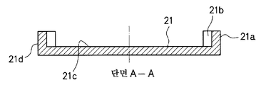
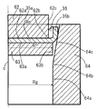
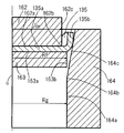
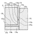
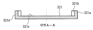
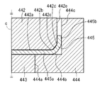
도 1d에 도시한 바와 같이, 치형 부품(11)은, 저면부(11a)와, 이 저면부(11a)의 외측 에지부로부터 기립하는 측벽부(11b)를 구비한다. 종래의 치형 부품의 제조 방법에서는, 저면부(11a)의 상면과 측벽부(11b)의 내주면과의 사이의 경계에, 측벽부(11b)의 내주면의 일부가 저면부(11a)의 상면에 겹침으로써 형성되는 흠집(11e)(이하, 겹침 흠집이라고 칭함)이 발생하는 경우가 있다.As shown in Fig. 1D, the
이하에, 겹침 흠집(11e)의 발생 메커니즘을 설명한다. 또한, 이하에서는, 설명의 편의상, 치형 부품(11)의 제조 과정에서 얻어지는 원통 용기에도 동일한 부호(11)를 사용한다. 도 1a에 도시한 바와 같이, 피가공재를 드로잉 성형함으로써 얻어진 원통 용기(11)를 다이(14) 상에 놓고, 구속 펀치(12)의 평면부(12a)와 다이(14)의 평면부(14a)로 원통 용기(11)의 저면부(11a)를 구속한다. 이 상태에서, 단압 펀치(13)의 평면부(13a)로 원통 용기(11)의 개구단부(11d)를 밀어 넣음으로써, 치형의 성형을 행한다. 도 1a에 도시한 바와 같이, 단압 성형 전에 있어서 원통 용기(11)의 코너부(11c)의 판 두께는, 저면부(11a) 및 측벽부(11b)의 판 두께보다 얇다. 도 1b에 도시한 바와 같이, 단압 성형이 개시되는, 즉 단압 펀치(13)의 하강 동작이 개시되면, 측벽부(11b)가 하방으로 눌려 찌부러짐으로써, 측벽부(11b)가 두꺼워진다. 그 때문에, 단압 성형의 과정에서, 코너부(11c)에 있어서 도면 중의 화살표 방향으로 재료 흐름이 발생하고, 그 결과, 코너부(11c)의 내면측과 구속 펀치(12)의 어깨 R부(12b)와의 사이에 간극(15)이 발생한다. 그 후, 단압 펀치(13)로 원통 용기(11)의 개구단부(11d)를 더 밀어 넣으면, 도 1c에 도시한 바와 같이, 측벽부(11b)의 내주면의 일부가 부풀어 올라 간극(15)에 유입된다. 그 결과, 도 1d에 도시한 바와 같이, 단압 성형 종료 후에, 측벽부(11b)의 내주면의 일부가 저면부(11a)의 상면에 겹침으로써, 저면부(11a)의 상면과 측벽부(11b)의 내주면과의 사이의 경계에 겹침 흠집(11e)이 형성된다.The generation mechanism of the overlapping
최근에는, 자동 변속 장치용 치형 부품과 같이 높은 치수 정밀도 및 강도가 요구되는 기계 부품의 제조 방법으로서, 냉간 단조가 주목받고 있다. 냉간 단조는, 열간 단조와 비교하여, 고정밀도 및 고강도의 기계 부품을 얻을 수 있고, 또한 제조 비용이 낮으면서 또한 수율이 높은 등의 이점을 갖는다.Recently, cold forging has attracted attention as a method of manufacturing mechanical parts requiring high dimensional accuracy and strength as in the case of a tooth part for an automatic transmission. The cold forging has advantages such as high precision and high strength mechanical parts as compared with hot forging, and low manufacturing cost and high yield.
그러나, 상기와 같은 치형 부품의 제조 과정에서 발생하는 겹침 흠집은, 수율 저하의 원인이 되므로, 냉간 단조를 채용함으로써 원래 얻어지는 고수율이라는 이점을 충분히 얻을 수 없다.However, the overlapping scratches generated in the manufacturing process of the tooth part as described above cause a decrease in the yield, so that the advantage of high yield obtained originally by cold forging can not be sufficiently obtained.
그 때문에, 높은 치수 정밀도 및 강도가 요구되는 치형 부품(즉, 높은 품질이 요구되는 치형 부품)의 제조 방법으로서 냉간 단조를 채용한 경우에도, 제조 과정에서 겹침 흠집이 발생하는 것을 억제함으로써 치형 부품의 수율을 향상시키는 것이 가능한 기술이 요구되고 있었다.Therefore, even when cold forging is employed as a manufacturing method of a toothed component (that is, a toothed component requiring high quality) requiring high dimensional accuracy and strength, it is possible to prevent the occurrence of overlapping scratches in the manufacturing process, A technique capable of improving the yield has been demanded.
본 발명은 상기 사정을 감안하여 이루어진 것이며, 치형 부품의 수율을 향상시키는 것이 가능한 치형 부품의 제조 방법 및 고품질의 치형 부품을 제공하는 것을 목적으로 한다.SUMMARY OF THE INVENTION It is an object of the present invention to provide a manufacturing method of a toothed component and a high-quality toothed component that can improve the yield of the toothed component.
본 발명은, 상기 과제를 해결하여 이러한 목적을 달성하기 위해 이하의 수단을 채용한다.The present invention solves the above problems and adopts the following means in order to achieve this object.
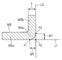
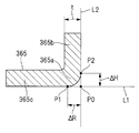
(1) 본 발명의 일 형태에 관한 치형 부품의 제조 방법은, 피가공재를 드로잉 성형함으로써, 저면부 및 측면부를 갖는 원통 용기를 얻는 드로잉 공정과; 상기 원통 용기의 상기 측면부 중, 치선부가 형성되는 특정 부위를 직경 축소함으로써, 상기 저면부와 상기 측면부와의 사이의 코너부를 두껍게 하는 직경 축소 공정과; 상기 직경 축소 공정에서 직경 축소된 상기 원통 용기의 상기 특정 부위에 상기 치선부를 형성함으로써, 상기 저면부, 상기 측면부 및 상기 치선부를 갖는 치형 부품을 얻는 치형 성형 공정; 을 갖는다. 상기 직경 축소 공정에서는, 상기 원통 용기의 중심축 방향 및 직경 방향을 포함하는 단면에서 상기 원통 용기를 본 경우에, 상기 원통 용기의 상기 저면부에 대하여 평행하게 접하는 직선(L1)과, 상기 원통 용기의 상기 측면부에 대하여 평행하게 접하는 직선(L2)과의 교점을 P0라 정의하고, 상기 직선(L1)이 상기 원통 용기의 상기 저면부로부터 이탈하기 시작하는 점을 P1, 상기 직선(L2)이 상기 원통 용기의 상기 측면부로부터 이탈하기 시작하는 점을 P2라 정의하고, 또한 상기 직선(L1) 상의 상기 교점(P0)과 상기 점(P1)과의 사이의 길이를 ΔR, 상기 직선(L2) 상의 상기 교점(P0)과 상기 점(P2)과의 사이의 길이를 ΔH라 정의했을 때, 상기 원통 용기의 상기 코너부의 외측의 형상이, 상기 원통 용기의 판 두께(t)와, 상기 길이(ΔR 및 ΔH)를 사용해서 표현되는 하기 조건식 (1)을 만족시키도록 상기 코너부를 두껍게 한다.(1) A method of manufacturing a toothed part according to one aspect of the present invention includes: a drawing step of obtaining a cylindrical container having a bottom surface portion and a side surface portion by drawing-forming a material to be processed; A diameter reducing step of increasing a diameter of a corner portion between the bottom surface portion and the side surface portion by reducing a diameter of a specific portion of the side surface portion of the cylindrical container where the tooth line portion is formed; A tooth forming step of obtaining a tooth part having the bottom face part, the side face part and the teeth tooth part by forming the teeth tooth part on the specific part of the diameter-reduced cylindrical container in the diameter reduction step; Respectively. In the diameter reduction process, when the cylindrical container is viewed in a cross section including a central axis direction and a radial direction of the cylindrical container, a straight line (L1) contacting in parallel with the bottom surface portion of the cylindrical container, A point at which the straight line L1 begins to depart from the bottom surface portion of the cylindrical container is defined as P1 and the straight line L2 is defined as a point at which the straight line L2 is in contact with the side surface of the cylindrical container, P2 is defined as a point starting to depart from the side surface of the cylindrical container and a length between the intersection point P0 on the straight line L1 and the point P1 is defined as DELTA R, The outer shape of the corner portion of the cylindrical container is defined by a relationship between the plate thickness t of the cylindrical container and the lengths DELTA R and DELTA R when the length between the intersection P0 and the point P2 is defined as DELTA H. [ DELTA H) The corner portion is thickened to satisfy the expression (1).
(ΔR+ΔH)≤2t … (1)(? R +? H)? 2t ... (One)
(2) 상기 (1)에 기재된 치형 부품의 제조 방법이, 상기 드로잉 공정에 의해 얻어진 상기 원통 용기의 상기 특정 부위를 직경 확장하는 직경 확장 공정을, 상기 드로잉 공정과 상기 직경 축소 공정과의 사이에 더 갖고 있어도 된다.(2) The method of manufacturing a toothed component according to (1) above, further includes a step of expanding the diameter of the specific portion of the cylindrical vessel obtained by the drawing step, between the drawing step and the diameter reduction step You can have more.
(3) 상기 (1) 또는 (2)에 기재된 치형 부품의 제조 방법에 있어서, 상기 치형 성형 공정이, 상기 직경 축소 공정에서 직경 축소된 상기 원통 용기의 상기 특정 부위에 거친 치형을 형성하는 거친 치형 성형 공정과; 상기 거친 치형을 가공함으로써 상기 특정 부위에 완성 치형을 상기 치선부로서 형성하는 완성 치형 성형 공정; 을 갖고 있어도 된다.(3) In the method of manufacturing a tooth part according to (1) or (2), the tooth forming step includes a step of forming a coarse tooth shape to form a coarse tooth shape on the specific portion of the cylindrical container, A molding process; A finished tooth profile forming step of forming a finished tooth profile on the specific portion by machining the rough tooth profile as the toothed portion; .
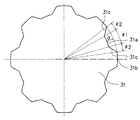
(4) 상기 (1) 내지 (3) 중 어느 하나에 기재된 치형 부품의 제조 방법에 있어서, 상기 피가공재가, 재축을 중심으로 하는 원주 방향을 따라 교대로 드러나게 설치된 산부 및 골부를 갖는 평판이며, 상기 산부는, 상기 골부로부터 상기 재축을 상기 중심으로 하는 직경 방향의 외측을 향해서 돌출되는 부위이어도 된다.(4) The method of manufacturing a toothed component according to any one of (1) to (3), wherein the work piece is a flat plate having a crest portion and a trough portion alternately exposed along a circumferential direction about the reclamation, The hill may be a portion protruding from the valley toward the outer side in the radial direction centering on the reconditioning.
(5) 상기 (1) 내지 (3) 중 어느 하나에 기재된 치형 부품의 제조 방법에 있어서, 상기 피가공재가, 원 형상의 평판, 또는 다각 형상이 평판이어도 된다.(5) In the method of manufacturing a toothed component according to any one of (1) to (3), the to-be-processed material may be a circular flat plate or a polygonal flat plate.
(6) 상기 (1)에 기재된 치형 부품의 제조 방법에 있어서, 상기 피가공재가, 재축을 중심으로 하는 원주 방향을 따라 교대로 드러나게 설치된 산부 및 골부를 갖는 평판이며, 상기 산부는, 상기 골부로부터 상기 재축을 상기 중심으로 하는 직경 방향의 외측을 향해서 돌출되는 부위이며; 상기 드로잉 공정에서는, 상기 원통 용기의 상기 측면부에, 상기 산부 및 상기 골부가 포함되도록, 상기 피가공재를 드로잉 성형하고; 상기 직경 축소 공정에서는, 상기 드로잉 공정에 의해 얻어진 상기 원통 용기의 상기 측면부에 포함되는 상기 산부를 상기 특정 부위로서 직경 축소해도 된다.(6) In the method of manufacturing a toothed component according to (1), the work piece is a flat plate having a crest and a crest portion alternately exposed along a circumferential direction around the crush, A portion protruding toward the outer side in the radial direction about the above-mentioned reconditioning; In the drawing step, the material to be processed is drawn and formed on the side portion of the cylindrical container so that the crest portion and the crest portion are included; In the diameter reduction step, the peak portion included in the side surface portion of the cylindrical container obtained by the drawing step may be reduced in diameter as the specific portion.
(7) 상기 (6)에 기재된 치형 부품의 제조 방법에서는, 상기 드로잉 공정에서, 중심축이 동축 상에 배치된, 펀치와, 다이를 사용하고; 상기 펀치는, 상기 중심축과 직교하는 직경 방향에 평행한 펀치 평면부와, 상기 펀치 평면부와 펀치 곡면부를 통해 연속하고, 상기 중심축과 평행한 제1 방향으로 연장되는 펀치 측면부를 갖고, 상기 펀치 측면부에는, 상기 제1 방향으로 연신되는 산근 및 골근이 형성되어 있고; 상기 다이는, 상기 중심축과 직교하는 직경 방향에 평행한 다이 평면부와, 상기 다이 평면부에 연속해서 상기 제1 방향으로 연장되는 다이 측면부를 갖고, 상기 다이 측면부에는, 상기 제1 방향으로 연신되는 산근 및 골근이 형성되어 있고; 상기 피가공재의 상기 산부가 상기 다이의 상기 골근에 위치하도록 상기 피가공재를 상기 다이 상에 놓고; 그 후, 상기 펀치를 상기 다이의 방향으로 상대 이동시킴으로써, 상기 측면부가 상기 저면부에 대하여 직립하는 상기 원통 용기를 얻어도 된다.(7) In the method of manufacturing a toothed component according to (6), in the drawing step, a punch and a die in which a central axis is arranged coaxially are used; Wherein the punch has a punch plane portion parallel to the radial direction perpendicular to the central axis and a punch side portion continuous with the punch plane portion and the punch curved portion and extending in a first direction parallel to the central axis, Wherein the punch side surface portion is formed with a thin rope and a rib extending in the first direction; Wherein the die has a die plane portion parallel to the radial direction perpendicular to the central axis and a die side surface portion extending in the first direction continuously to the die plane portion, ≪ / RTI > are formed; Placing the material to be processed on the die such that the apex of the material to be processed is located at the root of the die; Thereafter, by moving the punch relative to the die in the direction of the die, the cylindrical container in which the side portions stand upright with respect to the bottom portion can be obtained.
(8) 상기 (6) 또는 (7)에 기재된 치형 부품의 제조 방법에서는, 상기 직경 축소 공정에서, 중심축이 동축 상에 배치된, 펀치와, 카운터 펀치와, 상기 카운터 펀치의 외주에 배치되는 다이를 사용하고; 상기 펀치는, 상기 중심축과 직교하는 직경 방향에 평행한 펀치 평면부와, 상기 펀치 평면부와 펀치 곡면부를 통해 연속해서 상기 중심축과 평행한 제1 방향으로 연장되고, 또한 반경이 상기 치형 부품의 상기 치선부의 내측 반경과 동등한 펀치 측면부를 갖고; 상기 카운터 펀치는, 상기 중심축과 직교하는 직경 방향에 평행한 카운터 펀치 평면부와, 상기 카운터 펀치 평면부에 연속해서 상기 제1 방향과 역방향으로 신장되면서, 또한 반경이 상기 치형 부품의 상기 치선부의 외측 반경과 동등한 카운터 펀치 측면부를 갖고; 상기 다이는, 상기 제1 방향으로 연장되고, 또한 반경이 상기 치형 부품의 상기 치선부의 외측 반경과 동등한 다이 측면부와, 상기 다이 측면부와 다이 곡면부를 통해 연속하고, 상기 제1 방향으로 진행됨에 따라서 상기 중심축과 직교하는 방향으로 확대 개방되는 다이 경사부를 갖고; 상기 드로잉 공정에 의해 얻어진 상기 원통 용기의 상기 저면부를 상기 펀치와 상기 카운터 펀치와의 사이에 끼운 상태에서, 상기 펀치 및 상기 카운터 펀치를 상기 다이의 방향으로 상대 이동시킴으로써, 상기 원통 용기의 상기 측면부에 포함되는 상기 산부를 상기 특정 부위로서 직경 축소해도 된다.(8) In the method of manufacturing a toothed component according to (6) or (7), in the diameter reduction step, the punch, the counter punch, and the counter punch Using a die; Wherein the punch includes a punch plane portion that is parallel to the radial direction perpendicular to the central axis and a punch portion that extends continuously in a first direction parallel to the central axis via the punch plane portion and the punch curved portion, Has a punch side surface portion equal to an inner radius of the tooth line portion of the punch side portion; Wherein the counter punch includes a counter punch plane portion parallel to the radial direction perpendicular to the central axis and a counter punch plane portion extending in a direction opposite to the first direction continuously to the counter punch plane portion, And has counter punch side portions equal to the outside radius; Wherein the die comprises: a die side portion extending in the first direction and having a radius equal to an outer radius of the tooth line portion of the toothed portion; and a die side portion extending in the die side portion and the die curved portion, And a die inclined portion which is opened and expanded in a direction orthogonal to the central axis; The punch and the counter punch are relatively moved in the direction of the die in a state in which the bottom surface portion of the cylindrical container obtained by the drawing process is sandwiched between the punch and the counter punch, And the diameter of the mountain part included as the specific part may be reduced.
(9) 상기 (6) 내지 (8) 중 어느 하나에 기재된 치형 부품의 제조 방법에서는, 상기 치형 성형 공정에서, 중심축이 동축 상에 배치된, 내측 펀치와, 상기 내측 펀치의 외주에 배치되는 외측 펀치와, 카운터 펀치와, 상기 카운터 펀치의 외주에 배치되는 다이를 사용하고; 상기 내측 펀치는, 상기 중심축과 직교하는 직경 방향에 평행한 내측 펀치 평면부와, 상기 내측 펀치 평면부와 내측 펀치 곡면부를 통해 연속해서 상기 중심축에 평행한 제1 방향으로 연장되는 내측 펀치 측면부를 갖고, 상기 내측 펀치 측면부에는, 상기 제1 방향으로 연장되는 내측 펀치 산근 및 내측 펀치 골근이 형성되어 있고; 상기 다이는, 상기 제1 방향으로 연장되는 다이 측면부와, 상기 다이 측면부와 다이 곡면부를 통해 연속하고, 상기 제1 방향으로 진행됨에 따라서 상기 중심축과 직교하는 방향으로 확대 개방되는 다이 경사부를 갖고, 상기 다이 측면부에는, 상기 제1 방향으로 연장되는 다이 골근 및 다이 산근이 형성되어 있고; 상기 외측 펀치는, 상기 중심축과 직교하는 직경 방향에 평행한 외측 펀치 평면부와, 상기 외측 펀치 평면부에 연속해서 상기 내측 펀치 측면부를 따라 상기 제1 방향으로 연장되는 외측 펀치 제1 측면부와, 상기 외측 펀치 평면부에 연속해서 상기 다이 측면부를 따라 상기 제1 방향으로 연장되는 외측 펀치 제2 측면부를 갖고; 상기 카운터 펀치는, 상기 다이 측면부를 따라 상기 제1 방향으로 연장되는 카운터 펀치 측면부와, 상기 카운터 펀치 측면부에 연속해서 상기 중심축과 직교하는 직경 방향에 평행한 카운터 펀치 평면부를 갖고; 상기 직경 축소 공정에서 직경 축소된 상기 원통 용기의 상기 산부가 상기 다이 골근에 위치하도록, 상기 원통 용기의 상기 저면부를 상기 내측 펀치 평면부와 상기 카운터 펀치 평면부와의 사이에 끼운 상태에서, 상기 외측 펀치 평면부를 상기 원통 용기의 개구단부에 맞닿게 하고; 그 후, 상기 내측 펀치, 상기 외측 펀치 및 상기 카운터 펀치를 상기 다이의 방향으로 상대 이동시키고; 상기 외측 펀치 평면부가 상기 다이 곡면부를 통과한 후, 상기 내측 펀치, 상기 카운터 펀치 및 상기 다이를 고정한 상태에서, 상기 외측 펀치를 상기 카운터 펀치의 방향으로 상대 이동시킴으로써, 상기 원통 용기의 상기 산부에 상기 치선부를 형성해도 된다.(9) In the method of manufacturing a toothed component according to any one of (6) to (8), in the tooth forming process, an inner punch having a central axis disposed coaxially with the inner punch, An outer punch, a counter punch, and a die disposed on the outer periphery of the counter punch; Wherein the inner punch includes an inner punch plane portion parallel to the radial direction perpendicular to the central axis and an inner punch side surface portion extending continuously in a first direction parallel to the central axis through the inner punch plane portion and the inner punch curved portion, The inner punch side wall portion and the inner punch side wall portion extending in the first direction are formed on the inner punch side surface portion; Wherein the die has a die side surface portion extending in the first direction and a die inclined portion continuous with the die side surface portion and the die curved surface portion and expanded in a direction orthogonal to the central axis as proceeding in the first direction, The die side surface portion being formed with a die reinforcement and a die diaper extending in the first direction; Wherein the outer punch includes an outer punch plane portion parallel to the radial direction perpendicular to the central axis, an outer punch first lateral portion extending in the first direction along the inner punch side portion continuously to the outer punch plane portion, And an outer punch second side surface extending in the first direction along the die side surface continuously to the outer punch plane portion; Wherein the counter punch has a counter punch side surface portion extending in the first direction along the die side surface portion and a counter punch surface portion parallel to the radial direction perpendicular to the center axis continuously to the counter punch side surface portion; In a state where the bottom portion of the cylindrical container is sandwiched between the inner punch plane portion and the counter punch plane portion so that the peak portion of the cylindrical container reduced in diameter in the diameter reduction process is located at the die boss, The punch plane portion is brought into contact with the opening end of the cylindrical container; Then, the inner punch, the outer punch and the counter punch are relatively moved in the direction of the die; The counter punch, and the die are moved relative to each other in the direction of the counter punch after the outer punch plane portion passes the die curved surface portion, and the inner punch, the counter punch and the die are fixed, The teeth may be formed.
(10) 상기 (6) 내지 (8) 중 어느 하나에 기재된 치형 부품의 제조 방법에 있어서, 상기 치형 성형 공정이, 상기 직경 축소 공정에서 직경 축소된 상기 원통 용기의 상기 산부에 거친 치형을 형성하는 거친 치형 성형 공정과; 상기 거친 치형을 가공함으로써 상기 산부에 완성 치형을 상기 치선부로서 형성하는 완성 치형 성형 공정; 을 갖고 있어도 된다.(10) In the method of manufacturing a toothed component according to any one of (6) to (8), the tooth forming process may include forming a coarse tooth profile on the crest part of the diameter- A coarse tooth forming process; A finished tooth forming step of forming a finished tooth on the apex portion by machining the rough tooth profile as the teeth; .
(11) 상기 (10)에 기재된 치형 부품의 제조 방법에서는, 상기 거친 치형 성형 공정에서, 중심축이 동축 상에 배치된, 거친 치형 성형 내측 펀치와, 상기 거친 치형 성형 내측 펀치의 외주에 배치되는 거친 치형 성형 외측 펀치와, 거친 치형 성형 카운터 펀치와, 상기 거친 치형 성형 카운터 펀치의 외주에 배치되는 거친 치형 성형 다이를 사용하고; 상기 거친 치형 성형 내측 펀치는, 상기 중심축과 직교하는 직경 방향에 평행한 거친 치형 성형 내측 펀치 평면부와, 상기 거친 치형 성형 내측 펀치 평면부 및 거친 치형 성형 내측 펀치 곡면부를 통해 연속해서 상기 중심축에 평행한 제1 방향으로 연장되는 거친 치형 성형 내측 펀치 측면부를 갖고, 상기 거친 치형 성형 내측 펀치 측면부에는, 상기 제1 방향으로 연장되는 거친 치형 성형 내측 펀치 산근 및 거친 치형 성형 내측 펀치 골근이 형성되어 있고; 상기 거친 치형 성형 다이는, 상기 제1 방향으로 연장되는 거친 치형 성형 다이 측면부와, 상기 거친 치형 성형 다이 측면부 및 거친 치형 성형 다이 곡면부를 통해 연속하고, 상기 제1 방향으로 진행됨에 따라서 상기 중심축과 직교하는 방향으로 확대 개방되는 거친 치형 성형 다이 경사부를 갖고, 상기 거친 치형 성형 다이 측면부에는, 상기 제1 방향으로 연장되는 거친 치형 성형 다이 골근 및 거친 치형 성형 다이 산근이 형성되어 있고; 상기 거친 치형 성형 외측 펀치는, 상기 중심축과 직교하는 직경 방향에 평행한 거친 치형 성형 외측 펀치 평면부와, 상기 거친 치형 성형 외측 펀치 평면부에 연속해서 상기 거친 치형 성형 내측 펀치 측면부를 따라 상기 제1 방향으로 연장되는 거친 치형 성형 외측 펀치 제1 측면부와, 상기 거친 치형 성형 외측 펀치 평면부에 연속해서 상기 거친 치형 성형 다이 측면부를 따라 상기 제1 방향으로 연장되는 거친 치형 성형 외측 펀치 제2 측면부를 갖고; 상기 거친 치형 성형 카운터 펀치는, 상기 거친 치형 성형 다이 측면부를 따라 상기 제1 방향으로 연장되는 거친 치형 성형 카운터 펀치 측면부와, 상기 거친 치형 성형 카운터 펀치 측면부에 연속해서 상기 중심축과 직교하는 직경 방향에 평행한 거친 치형 성형 카운터 펀치 평면부를 갖고; 상기 직경 축소 공정에서 직경 축소된 상기 원통 용기의 상기 산부가 상기 거친 치형 성형 다이 골근에 위치하도록, 상기 원통 용기의 상기 저면부를 상기 거친 치형 성형 내측 펀치 평면부와 상기 거친 치형 성형 카운터 펀치 평면부와의 사이에 끼운 상태에서, 상기 거친 치형 성형 외측 펀치 평면부를 상기 원통 용기의 개구단부에 맞닿게 하고; 그 후, 상기 거친 치형 성형 내측 펀치, 상기 거친 치형 성형 외측 펀치 및 상기 거친 치형 성형 카운터 펀치를 상기 거친 치형 성형 다이의 방향으로 상대 이동시킴으로써, 상기 원통 용기의 상기 산부에 상기 거친 치형을 형성해도 된다.(11) In the method of manufacturing a toothed component according to (10), the coarse tooth-shaped inner punch is disposed coaxially with the central axis in the coarse tooth forming step, A coarse toothed forming outer punch, a coarse toothed forming counter punch, and a coarse tooth forming die disposed on the periphery of the coarse toothed forming counter punch; The coarse toothed forming inner punch includes a coarse toothed inner punch flat surface portion parallel to the radial direction perpendicular to the central axis and a coarse toothed inner punch flat surface portion continuously extending through the coarse toothed inner punch flat surface portion and the coarse toothed forming inner punch curved surface portion, Shaped coarse inner punch side face portion extending in the first direction is formed on the side face of the coarse toothed inner side punch portion and the coarse toothed inner side punch side face portion extending in the first direction is formed Have; The coarse tooth shaping die includes a coarse tooth shaping die side portion extending in the first direction and a plurality of coarse tooth shaping die curved portions extending along the coarse tooth shaping die side surface portion and the coarse tooth shaping die curved portion, Wherein the coarse tooth shaping die has a coarse tooth shaping die slope extending in the first direction and a coarse tooth shaping die slope extending in the first direction; The coarse toothed outer punch includes a coarse toothed outer punch plane portion that is parallel to the radial direction perpendicular to the central axis, and a coarse toothed outer punch plane portion that is continuous with the coarse toothed outer punch plane portion, Shaped outer punch second side portion extending in the first direction along the side surface of the coarse toothed molding die in succession to the coarse toothed outer punch flat surface portion of the coarse toothed forming outer punch extending in one direction Have; The coarse tooth-formed counter punch includes: a coarse tooth-shaped counter punch side portion extending in the first direction along the side surface of the coarse tooth shaping die; and a plurality of coarse teeth formed in the radial direction Having a parallel rough-tooth shaped counter punch plane portion; The bottom surface portion of the cylindrical container is positioned between the coarse toothed inner punch plane portion and the coarse toothed shaped counter punch plane portion so that the crest portion of the diameter- , The coarse tooth-shaped outer punch plane portion is brought into contact with the opening end portion of the cylindrical container; Then, the coarse tooth-shaped inner punch, the coarse tooth-shaped outer punch, and the coarse tooth-formed counter punch are moved relative to each other in the direction of the coarse tooth-shaping die to form the rough tooth profile on the crest portion of the cylindrical container .
(12) 상기 (11)에 기재된 치형 부품의 제조 방법에서는, 상기 완성 치형 성형 공정에서, 중심축이 동축 상에 배치된, 완성 치형 성형 내측 펀치와, 상기 완성 치형 성형 내측 펀치의 외주에 배치되는 완성 치형 성형 외측 펀치와, 완성 치형 성형 다이를 사용하고; 상기 완성 치형 성형 내측 펀치는, 상기 중심축과 직교하는 직경 방향에 평행한 완성 치형 성형 내측 펀치 평면부와, 상기 완성 치형 성형 내측 펀치 평면부 및 완성 치형 성형 내측 펀치 곡면부를 통해 연속해서 상기 중심축에 평행한 제1 방향으로 연장되는 완성 치형 성형 내측 펀치 측면부를 갖고, 상기 완성 치형 성형 내측 펀치 측면부는, 상기 중심축에 직교하는 단면의 형상 및 치수가 상기 거친 치형 성형 내측 펀치 측면부와 동일하고, 상기 제1 방향으로 연신되는 완성 치형 성형 내측 펀치 산근 및 완성 치형 성형 내측 펀치 골근을 갖고; 상기 완성 치형 성형 다이는, 상기 중심축과 직교하는 직경 방향에 평행한 완성 치형 성형 다이 평면부와, 상기 완성 치형 성형 다이 평면부에 연속해서 상기 제1 방향으로 연장되는 완성 치형 성형 다이 측면부를 갖고, 상기 완성 치형 성형 다이 측면부는, 상기 중심축에 직교하는 단면의 형상 및 치수가 상기 거친 치형 성형 다이 측면부와 동일하고, 상기 제1 방향으로 연신되는 완성 치형 성형 다이 산근 및 완성 치형 성형 다이 골근을 갖고; 상기 완성 치형 성형 외측 펀치는, 상기 중심축과 직교하는 직경 방향에 평행한 완성 치형 성형 외측 펀치 평면부와, 상기 완성 치형 성형 외측 펀치 평면부에 연속해서 상기 완성 치형 성형 내측 펀치 측면부를 따라 상기 제1 방향으로 연장되는 완성 치형 성형 외측 펀치 제1 측면부와, 상기 완성 치형 성형 외측 펀치 평면부에 연속해서 상기 완성 치형 성형 다이 측면부를 따라 상기 제1 방향으로 연장되는 완성 치형 성형 외측 펀치 제2 측면부를 갖고; 상기 거친 치형 성형 공정에서 상기 원통 용기의 상기 산부에 형성된 상기 거친 치형이 상기 완성 치형 성형 다이 골근에 위치하도록, 상기 원통 용기의 상기 저면부를 상기 완성 치형 성형 내측 펀치 평면부와 상기 완성 치형 성형 다이 평면부와의 사이에 끼운 상태에서, 상기 완성 치형 성형 외측 펀치 평면부로 상기 원통 용기의 개구단부를 밀어 넣음으로써, 상기 원통 용기의 상기 산부에 상기 완성 치형을 형성해도 된다.(12) The method of manufacturing a toothed component according to (11), further comprising: a complete toothed forming inner punch having a central axis coaxially disposed in the complete toothed forming step; A finished tooth forming outer punch, and a complete tooth forming die; Wherein the finished toothed inner punch includes a complete toothed inner punch plane portion parallel to the radial direction perpendicular to the central axis and a toothed inner punch plane portion successively extending through the finished toothed inner punch flat surface portion and the finished toothed inner punch curved portion, Shaped inner punch side face portion extending in a first direction parallel to the central axis, and the shape and dimensions of a cross section orthogonal to the central axis are the same as those of the coarse tooth-shaped inner side punch side face portion, A finished toothed inner punch hoop extending in the first direction and a finished toothed inner punch hoop; The complete toothed molding die has a finished tooth profile die flat portion parallel to the radial direction perpendicular to the central axis and a finished tooth profile die side portion extending in the first direction continuously to the flat surface of the finished tooth profile die , The side surface of the complete tooth shaping die has a shape and dimensions of a cross section orthogonal to the central axis are the same as those of the side surface of the rough tooth shaping die and the shape of the finished tooth shaping die hoop and the finished tooth shaping die hoop extending in the first direction Have; Wherein the finished toothed outer punch comprises a complete toothed forming outer punch plane portion parallel to the radial direction perpendicular to the central axis and a toothed forming outer punch plane portion that is continuous with the complete toothed forming inner punch flat portion, And a second side surface of the finished tooth forming outer punch extending in the first direction along the side surface of the finished tooth forming die in succession to the surface of the finished tooth forming outer punch, Have; The bottom surface portion of the cylindrical container is positioned between the finished tooth profile forming inner punch plane portion and the finished tooth profile die surface so that the coarse tooth profile formed on the mountain portion of the cylindrical container in the coarse tooth profile forming process is located in the finished tooth profile die groove. The finished tooth profile may be formed in the mountain part of the cylindrical container by pushing the opening end of the cylindrical container into the planar part of the finished tooth profile external punch in a state sandwiched between the cylindrical part and the finished part.
(13) 상기 (1)에 기재된 치형 부품의 제조 방법이, 상기 드로잉 공정에 의해 얻어진 상기 원통 용기의 상기 특정 부위를 직경 확장하는 직경 확장 공정을, 상기 드로잉 공정과 상기 직경 축소 공정과의 사이에 더 갖고; 상기 피가공재가, 재축을 중심으로 하는 원주 방향을 따라 교대로 드러나게 설치된 산부 및 골부를 갖는 평판이며, 상기 산부는, 상기 골부로부터 상기 재축을 상기 중심으로 하는 직경 방향의 외측을 향해서 돌출되는 부위이며; 상기 드로잉 공정에서는, 상기 원통 용기의 상기 측면부에, 상기 산부 및 상기 골부가 포함되도록, 상기 피가공재를 드로잉 성형하고; 상기 직경 확장 공정에서는, 상기 드로잉 공정에 의해 얻어진 상기 원통 용기의 상기 측면부에 포함되는 상기 산부가 변형된 돌기부를 상기 특정 부위로서 직경 확장하고; 상기 직경 축소 공정에서는, 상기 직경 확장 공정에서 직경 확장된 상기 원통 용기의 상기 돌기부를 직경 축소해도 된다.(13) The method of manufacturing a tooth part as described in (1) above, further comprises a step of expanding the diameter of the cylindrical portion of the cylindrical container obtained by the drawing step to expand the diameter of the specific portion, Have more; Wherein the material to be processed is a flat plate having a mountain portion and a valley portion alternately exposed in a circumferential direction around the reconditioning portion and the mountain portion is a portion protruding from the valley portion toward an outer side in a radial direction centering on the reconditioning ; In the drawing step, the material to be processed is drawn and formed on the side portion of the cylindrical container so that the crest portion and the crest portion are included; In the diameter expanding step, the protruding portion of the crest portion included in the side portion of the cylindrical container obtained by the drawing process is expanded as the specific portion; In the diameter reduction step, the protruding portion of the cylindrical container expanded in diameter in the diameter expanding process may be reduced in diameter.
(14) 상기 (13)에 기재된 치형 부품의 제조 방법에서는, 상기 직경 확장 공정에서, 중심축이 동축 상에 배치된, 제1 펀치와, 제1 다이를 사용한 제1 스텝과, 중심축이 동축 상에 배치된, 제2 펀치와, 제2 다이를 사용한 제2 스텝을 갖고; 상기 제1 펀치는, 상기 중심축과 직교하는 직경 방향에 평행한 제1 펀치 평면부와, 상기 제1 펀치 평면부 및 제1 펀치 제1 곡면부를 통해 연속하고, 상기 중심축과 평행한 제1 방향으로 진행됨에 따라서 상기 중심축과 직교하는 직경 방향으로 확대 개방되는 제1 펀치 경사부와, 상기 제1 펀치 경사부 및 제1 펀치 제2 곡면부를 통해 연속해서 상기 제1 방향으로 연장되는 제1 펀치 측면부를 갖고, 상기 제1 펀치 측면부에는, 상기 제1 방향으로 연신되는 산근 및 골근이 형성되어 있고; 상기 제1 다이는, 상기 중심축과 직교하는 직경 방향에 평행한 제1 다이 평면부와, 상기 제1 다이 평면부에 연속해서 상기 제1 방향으로 연장되는 제1 다이 측면부를 갖고, 상기 제1 다이 측면부에는, 상기 제1 방향으로 연신되는 산근 및 골근이 형성되어 있고, 또한 상기 제1 다이 측면부는, 상기 제1 펀치 측면부로부터 직경 방향으로 상기 피가공재의 판 두께 분을 오프셋한 형태로 배치되고; 상기 제2 펀치는, 상기 중심축과 직교하는 직경 방향에 평행한 제2 펀치 평면부와, 상기 제2 펀치 평면부 및 제2 펀치 곡면부를 통해 연속해서 상기 제1 방향으로 연장되는 제2 펀치 측면부를 갖고, 상기 제2 펀치 측면부는, 형상 및 치수가 상기 제1 펀치 측면부와 동일하고, 상기 제1 방향으로 연신되는 산근 및 골근이 형성되어 있고; 상기 제2 다이는, 상기 중심축과 직교하는 직경 방향에 평행한 제2 다이 평면부와, 상기 제2 다이 평면부에 연속해서 상기 제1 방향으로 연장되는 제2 다이 측면부를 갖고, 상기 제2 다이 측면부는, 형상 및 치수가 상기 제1 다이 측면부와 동일하고, 상기 제1 방향으로 연신되는 산근 및 골근이 형성되어 있고; 상기 제1 스텝에서는, 상기 드로잉 공정에 의해 얻어지는 상기 원통 용기의 상기 산부가 변형된 상기 돌기부가 상기 제1 다이의 상기 골근에 위치하도록 상기 원통 용기를 상기 제1 다이 상에 놓고; 그 후, 상기 제1 펀치를 상기 제1 다이의 방향으로 상대 이동시킴으로써, 상기 돌기부를 직경 확장하고; 상기 제2 스텝에서는, 직경 확장된 상기 돌기부가 상기 제2 다이의 상기 골근에 위치하도록 상기 원통 용기를 상기 제2 다이 상에 놓고; 그 후, 상기 제2 펀치를 상기 제2 다이의 방향으로 상대 이동시킴으로써, 상기 측면부가 상기 저면부에 대하여 직립하는 상기 원통 용기를 얻어도 된다.(14) In the method of manufacturing a toothed component according to (13), in the step of expanding the diameter, a first punch having a central axis coaxially arranged, a first step using a first die, A second punch disposed on the first die, and a second step using the second die; Wherein the first punch includes a first punch plane portion that is parallel to the radial direction perpendicular to the central axis, and a second punch plane portion that is continuous with the first punch plane portion and the first punch first curved portion, The first punch inclined portion extending in the radial direction orthogonal to the central axis as it proceeds in the first punch inclined portion and the first punch second curved portion, and a second punch inclined portion continuously extended in the first direction through the first punch inclined portion and the first punch second curved portion, Wherein the first punch side surface portion has a thin rope and a rib extending in the first direction; Wherein the first die has a first die plane portion parallel to the radial direction perpendicular to the central axis and a first die side surface portion extending in the first direction continuously to the first die plane portion, Wherein the first die side surface portion is disposed offset from the first punch side surface portion in the radial direction by a plate thickness portion of the material to be processed offset in the die side surface portion ; The second punch includes a second punch plane portion that is parallel to the radial direction perpendicular to the center axis and a second punch side surface portion that continuously extends in the first direction through the second punch plane portion and the second punch curved portion, Wherein the second punch side surface portion has the same shape and dimensions as the first punch side surface portion and has a thinning bar and a thickening extending in the first direction; Wherein the second die has a second die plane portion parallel to the radial direction orthogonal to the central axis and a second die side surface portion continuous to the second die plane portion in the first direction, Wherein the die side surface portion has the same shape and dimensions as the first die side surface portion, and has a thin line and a thick line extending in the first direction; Placing the cylindrical container on the first die so that the protruding portion of the cylindrical portion of the cylindrical container obtained by the drawing process is deformed to the root of the first die; Thereafter, by relatively moving the first punch in the direction of the first die, the protrusions are expanded in diameter; Placing the cylindrical container on the second die such that the enlarged protrusion is located at the back root of the second die; Thereafter, by moving the second punch relative to the second die in the direction of the second die, the cylindrical container in which the side portions stand upright with respect to the bottom surface portion may be obtained.
(15) 상기 (13) 또는 (14)에 기재된 치형 부품의 제조 방법에서는, 상기 직경 축소 공정에서, 중심축이 동축 상에 배치된, 펀치와, 카운터 펀치와, 상기 카운터 펀치의 외주에 배치되는 다이를 사용하고; 상기 펀치는, 상기 중심축과 직교하는 직경 방향에 평행한 펀치 평면부와, 상기 펀치 평면부 및 펀치 곡면부를 통해 연속해서 상기 중심축과 평행한 제1 방향으로 연장되고, 또한 반경이 상기 치형 부품의 상기 치선부의 내측 반경과 동등한 펀치 측면부를 갖고; 상기 카운터 펀치는, 상기 중심축과 직교하는 직경 방향에 평행한 카운터 펀치 평면부와, 상기 카운터 펀치 평면부에 연속해서 상기 제1 방향과 역방향으로 연장되고, 또한 반경이 상기 치형 부품의 상기 치선부의 외측 반경과 동등한 카운터 펀치 측면부를 갖고; 상기 다이는, 상기 제1 방향으로 연장되고, 또한 반경이 상기 치형 부품의 상기 치선부의 외측 반경과 동등한 다이 측면부와, 상기 다이 측면부 및 다이 곡면부를 통해 연속하고, 상기 제1 방향으로 진행됨에 따라서 상기 중심축과 직교하는 방향으로 확대 개방되는 다이 경사부를 갖고; 상기 직경 확장 공정에 의해 직경 확장된 상기 돌기부를 갖는 상기 원통 용기의 상기 저면부를 상기 펀치와 상기 카운터 펀치와의 사이에 끼운 상태에서, 상기 펀치 및 상기 카운터 펀치를 상기 다이의 방향으로 상대 이동시킴으로써, 상기 원통 용기의 상기 측면부에 포함되는 상기 돌기부를 직경 축소해도 된다.(15) In the method of manufacturing a toothed component according to (13) or (14), in the diameter reduction step, a punch, a counter punch, and a counter punch Using a die; Wherein the punch includes a punch plane portion parallel to the radial direction orthogonal to the central axis and a punch plane portion extending continuously in a first direction parallel to the central axis through the punch plane portion and the punch curved portion, Has a punch side surface portion equal to an inner radius of the tooth line portion of the punch side portion; Wherein the counter punch includes a counter punch plane portion parallel to the radial direction perpendicular to the central axis and a counter punch plane portion extending in a direction opposite to the first direction continuously to the counter punch plane portion, And has counter punch side portions equal to the outside radius; Wherein the die comprises a die side portion extending in the first direction and having a radius equal to an outer radius of the tooth line portion of the toothed portion, and a die side portion extending in the die side portion and the die curved portion, And a die inclined portion which is opened and expanded in a direction orthogonal to the central axis; The punch and the counter punch are relatively moved in the direction of the die in a state in which the bottom surface portion of the cylindrical container having the protruding portion expanded in diameter by the diameter expansion process is sandwiched between the punch and the counter punch, The protruding portion included in the side portion of the cylindrical container may be reduced in diameter.
(16) 상기 (13) 내지 (15) 중 어느 하나에 기재된 치형 부품의 제조 방법에서는, 상기 치형 성형 공정에서, 중심축이 동축 상에 배치된, 내측 펀치와, 상기 내측 펀치의 외주에 배치되는 외측 펀치와, 카운터 펀치와, 상기 카운터 펀치의 외주에 배치되는 다이를 사용하고; 상기 내측 펀치는, 상기 중심축과 직교하는 직경 방향에 평행한 내측 펀치 평면부와, 상기 내측 펀치 평면부 및 내측 펀치 곡면부를 통해 연속해서 상기 중심축에 평행한 제1 방향으로 연장되는 내측 펀치 측면부를 갖고, 상기 내측 펀치 측면부에는, 상기 제1 방향으로 연장되는 내측 펀치 산근 및 내측 펀치 골근이 형성되어 있고; 상기 다이는, 상기 제1 방향으로 연장되는 다이 측면부와, 상기 다이 측면부 및 다이 곡면부를 통해 연속하고, 상기 제1 방향으로 진행됨에 따라서 상기 중심축과 직교하는 방향으로 확대 개방되는 다이 경사부를 갖고, 상기 다이 측면부에는, 상기 제1 방향으로 연장되는 다이 골근 및 다이 산근이 형성되어 있고; 상기 외측 펀치는, 상기 중심축과 직교하는 직경 방향에 평행한 외측 펀치 평면부와, 상기 외측 펀치 평면부에 연속해서 상기 내측 펀치 측면부를 따라 상기 제1 방향으로 연장되는 외측 펀치 제1 측면부와, 상기 외측 펀치 평면부에 연속해서 상기 다이 측면부를 따라 상기 제1 방향으로 연장되는 외측 펀치 제2 측면부를 갖고; 상기 카운터 펀치는, 상기 다이 측면부를 따라 상기 제1 방향으로 연장되는 카운터 펀치 측면부와, 상기 카운터 펀치 측면부에 연속해서 상기 중심축과 직교하는 직경 방향에 평행한 카운터 펀치 평면부를 갖고; 상기 직경 축소 공정에 의해 직경 축소된 상기 돌기부가 상기 다이 골근에 위치하도록, 상기 원통 용기의 상기 저면부를 상기 내측 펀치 평면부와 상기 카운터 펀치 평면부와의 사이에 끼운 상태에서, 상기 외측 펀치 평면부를 상기 원통 용기의 개구단부에 맞닿게 하고; 그 후, 상기 내측 펀치, 상기 외측 펀치 및 상기 카운터 펀치를 상기 다이의 방향으로 상대 이동시키고; 상기 외측 펀치 평면부가 상기 다이 곡면부를 통과한 후, 상기 내측 펀치, 상기 카운터 펀치 및 상기 다이를 고정한 상태에서, 상기 외측 펀치를 상기 카운터 펀치의 방향으로 상대 이동시킴으로써, 상기 원통 용기의 상기 돌기부에 상기 치선부를 형성해도 된다.(16) In the method of manufacturing a toothed component according to any one of (13) to (15), in the tooth forming process, an inner punch having a central axis disposed coaxially with the inner punch, An outer punch, a counter punch, and a die disposed on the outer periphery of the counter punch; Wherein the inner punch includes an inner punch plane portion parallel to the radial direction perpendicular to the central axis and an inner punch side surface portion extending continuously in a first direction parallel to the central axis through the inner punch plane portion and the inner punch curved portion, The inner punch side wall portion and the inner punch side wall portion extending in the first direction are formed on the inner punch side surface portion; Wherein the die has a die side face portion extending in the first direction and a die incline portion extending continuously through the die side face portion and the die curved face portion and expanded in a direction orthogonal to the central axis as proceeding in the first direction, The die side surface portion being formed with a die reinforcement and a die diaper extending in the first direction; Wherein the outer punch includes an outer punch plane portion parallel to the radial direction perpendicular to the central axis, an outer punch first lateral portion extending in the first direction along the inner punch side portion continuously to the outer punch plane portion, And an outer punch second side surface extending in the first direction along the die side surface continuously to the outer punch plane portion; Wherein the counter punch has a counter punch side surface portion extending in the first direction along the die side surface portion and a counter punch surface portion parallel to the radial direction perpendicular to the center axis continuously to the counter punch side surface portion; The inner punch plane portion and the counter punch plane portion are sandwiched between the inner punch plane portion and the counter punch plane portion so that the protruding portion reduced in diameter by the diameter reduction process is located at the die boss, To abut the opening end of the cylindrical container; Then, the inner punch, the outer punch and the counter punch are relatively moved in the direction of the die; Wherein the outer punch is relatively moved in the direction of the counter punch in a state in which the inner punch, the counter punch and the die are fixed after the outer punch plane portion passes the die curved portion, The teeth may be formed.
(17) 상기 (13) 내지 (15) 중 어느 하나에 기재된 치형 부품의 제조 방법에서는, 상기 치형 성형 공정이, 상기 직경 축소 공정에서 직경 축소된 상기 원통 용기의 상기 돌기부에 거친 치형을 형성하는 거친 치형 성형 공정과; 상기 거친 치형을 가공함으로써 상기 돌기부에 완성 치형을 상기 치선부로서 형성하는 완성 치형 성형 공정; 을 갖고 있어도 된다.(17) In the method of manufacturing a toothed component according to any one of (13) to (15), the tooth forming step is a step of forming a coarse tooth shape on the protruding portion of the cylindrical container, A tooth forming process; A finished tooth forming step of forming a finished tooth on the protruding portion by machining the coarse tooth shape as the teeth; .
(18) 상기 (17)에 기재된 치형 부품의 제조 방법에서는, 상기 거친 치형 성형 공정에서, 중심축이 동축 상에 배치된, 거친 치형 성형 내측 펀치와, 상기 거친 치형 성형 내측 펀치의 외주에 배치되는 거친 치형 성형 외측 펀치와, 거친 치형 성형 카운터 펀치와, 상기 거친 치형 성형 카운터 펀치의 외주에 배치되는 거친 치형 성형 다이를 사용하고; 상기 거친 치형 성형 내측 펀치는, 상기 중심축과 직교하는 직경 방향에 평행한 거친 치형 성형 내측 펀치 평면부와, 상기 거친 치형 성형 내측 펀치 평면부 및 거친 치형 성형 내측 펀치 곡면부를 통해 연속해서 상기 중심축에 평행한 제1 방향으로 연장되는 거친 치형 성형 내측 펀치 측면부를 갖고, 상기 거친 치형 성형 내측 펀치 측면부에는, 상기 제1 방향으로 연장되는 거친 치형 성형 내측 펀치 산근 및 거친 치형 성형 내측 펀치 골근이 형성되어 있고; 상기 거친 치형 성형 다이는, 상기 제1 방향으로 연장되는 거친 치형 성형 다이 측면부와, 상기 거친 치형 성형 다이 측면부 및 거친 치형 성형 다이 곡면부를 통해 연속하고, 상기 제1 방향으로 진행됨에 따라서 상기 중심축과 직교하는 방향으로 확대 개방되는 거친 치형 성형 다이 경사부를 갖고, 상기 거친 치형 성형 다이 측면부에는, 상기 제1 방향으로 연장되는 거친 치형 성형 다이 골근 및 거친 치형 성형 다이 산근이 형성되어 있고; 상기 거친 치형 성형 외측 펀치는, 상기 중심축과 직교하는 직경 방향에 평행한 거친 치형 성형 외측 펀치 평면부와, 상기 거친 치형 성형 외측 펀치 평면부에 연속해서 상기 거친 치형 성형 내측 펀치 측면부를 따라 상기 제1 방향으로 연장되는 거친 치형 성형 외측 펀치 제1 측면부와, 상기 거친 치형 성형 외측 펀치 평면부에 연속해서 상기 거친 치형 성형 다이 측면부를 따라 상기 제1 방향으로 연장되는 거친 치형 성형 외측 펀치 제2 측면부를 갖고; 상기 거친 치형 성형 카운터 펀치는, 상기 거친 치형 성형 다이 측면부를 따라 상기 제1 방향으로 연장되는 거친 치형 성형 카운터 펀치 측면부와, 상기 거친 치형 성형 카운터 펀치 측면부에 연속해서 상기 중심축과 직교하는 직경 방향에 평행한 거친 치형 성형 카운터 펀치 평면부를 갖고; 상기 직경 축소 공정에 의해 직경 축소된 상기 돌기부가 상기 거친 치형 성형 다이 골근에 위치하도록, 상기 원통 용기의 상기 저면부를 상기 거친 치형 성형 내측 펀치 평면부와 상기 거친 치형 성형 카운터 펀치 평면부와의 사이에 끼운 상태에서, 상기 거친 치형 성형 외측 펀치 평면부를 상기 원통 용기의 개구단부에 맞닿게 하고; 그 후, 상기 거친 치형 성형 내측 펀치, 상기 거친 치형 성형 외측 펀치 및 상기 거친 치형 성형 카운터 펀치를 상기 거친 치형 성형 다이의 방향으로 상대 이동시킴으로써, 상기 원통 용기의 상기 돌기부에 상기 거친 치형을 형성해도 된다.(18) In the method of manufacturing a toothed component according to (17), the coarse tooth-shaped inner punch in which the central axis is disposed coaxially in the coarse tooth forming step, A coarse toothed forming outer punch, a coarse toothed forming counter punch, and a coarse tooth forming die disposed on the periphery of the coarse toothed forming counter punch; The coarse toothed forming inner punch includes a coarse toothed inner punch flat surface portion parallel to the radial direction perpendicular to the central axis and a coarse toothed inner punch flat surface portion continuously extending through the coarse toothed inner punch flat surface portion and the coarse toothed forming inner punch curved surface portion, Shaped coarse inner punch side face portion extending in the first direction is formed on the side face of the coarse toothed inner side punch portion and the coarse toothed inner side punch side face portion extending in the first direction is formed Have; The coarse tooth shaping die includes a coarse tooth shaping die side portion extending in the first direction and a plurality of coarse tooth shaping die curved portions extending along the coarse tooth shaping die side surface portion and the coarse tooth shaping die curved portion, Wherein the coarse tooth shaping die has a coarse tooth shaping die slope extending in the first direction and a coarse tooth shaping die slope extending in the first direction; The coarse toothed outer punch includes a coarse toothed outer punch plane portion that is parallel to the radial direction perpendicular to the central axis, and a coarse toothed outer punch plane portion that is continuous with the coarse toothed outer punch plane portion, Shaped outer punch second side portion extending in the first direction along the side surface of the coarse toothed molding die in succession to the coarse toothed outer punch flat surface portion of the coarse toothed forming outer punch extending in one direction Have; The coarse tooth-formed counter punch includes: a coarse tooth-shaped counter punch side portion extending in the first direction along the side surface of the coarse tooth shaping die; and a plurality of coarse teeth formed in the radial direction Having a parallel rough-tooth shaped counter punch plane portion; And the bottom face of the cylindrical container is positioned between the coarse toothed inner punch plane portion and the coarse toothed shaped counter punch plane portion so that the diameter of the projecting portion is reduced by the diameter reduction process, The coarse tooth-shaped outer punch plane portion is brought into contact with the opening end portion of the cylindrical container; Thereafter, the coarse tooth-shaped inner punch, the coarse tooth-shaped outer punch, and the coarse tooth-formed counter punch may be relatively moved in the direction of the coarse tooth shaping die to form the coarse tooth shape on the projection of the cylindrical container .
(19) 상기 (18)에 기재된 치형 부품의 제조 방법에서는, 상기 완성 치형 성형 공정에서, 중심축이 동축 상에 배치된, 완성 치형 성형 내측 펀치와, 상기 완성 치형 성형 내측 펀치의 외주에 배치되는 완성 치형 성형 외측 펀치와, 완성 치형 성형 다이를 사용하고; 상기 완성 치형 성형 내측 펀치는, 상기 중심축과 직교하는 직경 방향에 평행한 완성 치형 성형 내측 펀치 평면부와, 상기 완성 치형 성형 내측 펀치 평면부 및 완성 치형 성형 내측 펀치 곡면부를 통해 연속해서 상기 중심축에 평행한 제1 방향으로 연장되는 완성 치형 성형 내측 펀치 측면부를 갖고, 상기 완성 치형 성형 내측 펀치 측면부는, 상기 중심축에 직교하는 단면의 형상 및 치수가 상기 거친 치형 성형 내측 펀치 측면부와 동일하고, 상기 제1 방향으로 연신되는 완성 치형 성형 내측 펀치 산근 및 완성 치형 성형 내측 펀치 골근을 갖고; 상기 완성 치형 성형 다이는, 상기 중심축과 직교하는 직경 방향에 평행한 완성 치형 성형 다이 평면부와, 상기 완성 치형 성형 다이 평면부에 연속해서 상기 제1 방향으로 연장되는 완성 치형 성형 다이 측면부를 갖고, 상기 완성 치형 성형 다이 측면부는, 상기 중심축에 직교하는 단면의 형상 및 치수가 상기 거친 치형 성형 다이 측면부와 동일하고, 상기 제1 방향으로 연신되는 완성 치형 성형 다이 산근 및 완성 치형 성형 다이 골근을 갖고; 상기 완성 치형 성형 외측 펀치는, 상기 중심축과 직교하는 직경 방향에 평행한 완성 치형 성형 외측 펀치 평면부와, 상기 완성 치형 성형 외측 펀치 평면부에 연속해서 상기 완성 치형 성형 내측 펀치 측면부를 따라 상기 제1 방향으로 연장되는 완성 치형 성형 외측 펀치 제1 측면부와, 상기 완성 치형 성형 외측 펀치 평면부에 연속해서 상기 완성 치형 성형 다이 측면부를 따라 상기 제1 방향으로 연장되는 완성 치형 성형 외측 펀치 제2 측면부를 갖고; 상기 거친 치형 성형 공정에서 상기 원통 용기의 상기 돌기부에 형성된 상기 거친 치형이 상기 완성 치형 성형 다이 골근에 위치하도록, 상기 원통 용기의 상기 저면부를 상기 완성 치형 성형 내측 펀치 평면부와 상기 완성 치형 성형 다이 평면부와의 사이에 끼운 상태에서, 상기 완성 치형 성형 외측 펀치 평면부로 상기 원통 용기의 개구단부를 밀어 넣음으로써, 상기 원통 용기의 상기 돌기부에 상기 완성 치형을 형성해도 된다.(19) In the method of manufacturing a toothed component according to (18), the complete toothed inner punch is disposed on the outer periphery of the complete toothed inner punch, A finished tooth forming outer punch, and a complete tooth forming die; Wherein the finished toothed inner punch includes a complete toothed inner punch plane portion parallel to the radial direction perpendicular to the central axis and a toothed inner punch plane portion successively extending through the finished toothed inner punch flat surface portion and the finished toothed inner punch curved portion, Shaped inner punch side face portion extending in a first direction parallel to the central axis, and the shape and dimensions of a cross section orthogonal to the central axis are the same as those of the coarse tooth-shaped inner side punch side face portion, A finished toothed inner punch hoop extending in the first direction and a finished toothed inner punch hoop; The complete toothed molding die has a finished tooth profile die flat portion parallel to the radial direction perpendicular to the central axis and a finished tooth profile die side portion extending in the first direction continuously to the flat surface of the finished tooth profile die , The side surface of the complete tooth shaping die has a shape and dimensions of a cross section orthogonal to the central axis are the same as those of the side surface of the rough tooth shaping die and the shape of the finished tooth shaping die hoop and the finished tooth shaping die hoop extending in the first direction Have; Wherein the finished toothed outer punch comprises a complete toothed forming outer punch plane portion parallel to the radial direction perpendicular to the central axis and a toothed forming outer punch plane portion that is continuous with the complete toothed forming inner punch flat portion, And a second side surface of the finished tooth forming outer punch extending in the first direction along the side surface of the finished tooth forming die in succession to the surface of the finished tooth forming outer punch, Have; The bottom surface portion of the cylindrical container is positioned between the finished tooth profile inner punch plane portion and the finished tooth profile die surface in the coarse tooth profile forming process so that the coarse tooth profile formed on the projecting portion of the cylindrical container is located in the finished tooth profile die groove. The finished teeth may be formed on the projecting portion of the cylindrical container by pushing the opening end of the cylindrical container into the planar portion of the finished tooth-formed outer punch in a state sandwiched between the cylindrical portion and the finished portion.
(20) 상기 (1)에 기재된 치형 부품의 제조 방법이, 상기 드로잉 공정에 의해 얻어진 상기 원통 용기의 상기 특정 부위를 직경 확장하는 직경 확장 공정을, 상기 드로잉 공정과 상기 직경 축소 공정과의 사이에 더 갖고; 상기 드로잉 공정에서는, 원 형상의 평판인 상기 피가공재를 드로잉 성형함으로써, 상기 원통 용기를 얻어도 된다.(20) The method of manufacturing a toothed component according to (1) above, further comprises a step of expanding the diameter of the cylindrical portion of the cylindrical container obtained by the drawing process to enlarge the diameter of the specific portion between the drawing step and the diameter- Have more; In the drawing step, the cylindrical container may be obtained by drawing-forming the material to be processed, which is a circular flat plate.
(21) 상기 (20)에 기재된 치형 부품의 제조 방법에서는, 상기 직경 확장 공정에서, 중심축이 동축 상에 배치된 제1 펀치와 제1 다이를 사용한 제1 스텝과, 중심축이 동축 상에 배치된 제2 펀치와 제2 다이를 사용한 제2 스텝을 갖고; 상기 제1 펀치는, 상기 중심축과 직교하는 직경 방향에 평행한 제1 펀치 평면부와, 상기 제1 펀치 평면부 및 제1 펀치 제1 곡면부를 통해 연속하고, 상기 중심축과 평행한 제1 방향으로 진행됨에 따라서 상기 중심축과 직교하는 직경 방향으로 확대 개방되는 제1 펀치 경사부와, 상기 제1 펀치 경사부와 제1 펀치 제2 곡면부를 통해 연속해서 상기 제1 방향으로 연신되는 제1 펀치 측면부를 갖고, 상기 제1 펀치 측면부에는, 상기 제1 방향으로 연신되는 산근 및 골근이 형성되어 있고; 상기 제1 다이는, 상기 제1 방향으로 연신되는 제1 다이 제1 측면부와, 상기 제1 다이 제1 측면부에 연속해서 상기 중심축과 직교하는 직경 방향에 평행한 제1 다이 평면부와, 상기 제1 다이 평면부에 연속해서 상기 제1 방향으로 연신되는 제1 다이 제2 측면부를 갖고, 상기 제1 다이 제2 측면부는, 상기 제1 펀치 측면부로부터 직경 방향으로 상기 피가공재의 판 두께 분을 오프셋한 산근 및 골근을 갖고; 상기 제2 펀치는, 상기 중심축과 직교하는 직경 방향에 평행한 제2 펀치 평면부와, 상기 제2 펀치 평면부 및 제2 펀치 곡면부를 통해 연속해서 상기 제1 방향으로 연신되는 제2 펀치 측면부를 갖고, 상기 제2 펀치 측면부는, 형상 및 치수가 상기 제1 펀치 측면부와 동일하고, 상기 제1 방향으로 연신되는 산근 및 골근이 형성되어 있고; 상기 제2 다이는, 상기 제1 방향으로 연신되는 제2 다이 제1 측면부와, 상기 제2 다이 제1 측면부에 연속해서 상기 중심축과 직교하는 직경 방향에 평행한 제2 다이 평면부와, 상기 제2 다이 평면부에 연속해서 상기 제1 방향으로 연신되는 제2 다이 제2 측면부를 갖고, 상기 제2 다이 제2 측면부는, 형상 및 치수가 상기 제1 다이 제2 측면부와 동일하고, 상기 제1 방향으로 연신되는 산근 및 골근이 형성되어 있고; 상기 제1 스텝에서는, 상기 드로잉 공정에 의해 얻어지는 상기 원통 용기를 상기 제1 다이 상에 놓고; 그 후, 상기 제1 펀치를 상기 제1 다이의 방향으로 상대 이동시킴으로써, 상기 제1 펀치의 산근에 의해 상기 측면부에 포함되는 상기 특정 부위를 직경 확장하고; 상기 제2 스텝에서는, 직경 확장된 상기 특정 부위가 상기 제2 다이의 상기 골근에 위치하도록 상기 원통 용기를 상기 제2 다이 평면부 상에 놓고; 그 후, 상기 제2 펀치를 상기 제2 다이의 방향으로 상대 이동시킴으로써, 상기 측면부가 상기 저면부에 대하여 직립하는 상기 원통 용기를 얻어도 된다.(21) In the method of manufacturing a toothed component according to (20), in the step of expanding the diameter, a first step using a first punch and a first die in which a central axis is arranged coaxially, And a second step using a second punch and a second die arranged; Wherein the first punch includes a first punch plane portion that is parallel to the radial direction perpendicular to the central axis, and a second punch plane portion that is continuous with the first punch plane portion and the first punch first curved portion, A first punch inclined portion extending in the radial direction orthogonal to the central axis as it progresses in the direction of the first punch inclined portion and the first punch inclined portion, and a second punch inclined portion continuously extended in the first direction through the first punch inclined portion and the first punch second curved portion, Wherein the first punch side surface portion has a thin rope and a rib extending in the first direction; Wherein the first die includes a first die first side surface portion extending in the first direction, a first die planar portion parallel to the radial direction perpendicular to the central axis continuously to the first die first side surface portion, Wherein the first die has a second die side surface portion extending in the first direction continuously to the first die plane portion and the first die second side surface portion has a plate thickness portion of the material to be processed in a radial direction from the first punch side surface portion Having offset sunburn and bone; The second punch includes a second punch plane portion that is parallel to the radial direction perpendicular to the center axis and a second punch side surface portion that is continuously extended in the first direction through the second punch plane portion and the second punch curved portion, Wherein the second punch side surface portion has the same shape and dimensions as the first punch side surface portion and has a thinning bar and a thickening extending in the first direction; Wherein the second die comprises: a second die first side surface portion extending in the first direction; a second die plane surface portion parallel to the radial direction orthogonal to the central axis continuously to the second die first side surface portion; And a second die second side surface portion extending in the first direction continuously to the second die plane portion, wherein the second die second side surface portion has the same shape and dimensions as the first die second side surface portion, The mountain roots and the bone roots extending in one direction are formed; In the first step, the cylindrical container obtained by the drawing step is placed on the first die; And then relatively moving the first punch in the direction of the first die to enlarge the specific portion included in the side portion by the roots of the first punch; Placing the cylindrical container on the second die plane portion such that the diameter-enlarged specific portion is located in the reinforcement of the second die; Thereafter, by moving the second punch relative to the second die in the direction of the second die, the cylindrical container in which the side portions stand upright with respect to the bottom surface portion may be obtained.
(22) 상기 (20) 또는 (21)에 기재된 치형 부품의 제조 방법에서는, 상기 직경 축소 공정에서, 펀치와, 상기 펀치와 중심축이 동축 상에 배치되는 카운터 펀치와, 상기 카운터 펀치의 외주를 따라서 배치되는 다이를 사용하고; 상기 펀치는, 상기 중심축과 직교하는 직경 방향에 평행한 펀치 평면부와, 상기 펀치 평면부 및 펀치 곡면부를 통해 연속해서 중심축을 따라 상기 중심축에 평행한 제1 방향으로 연신되고, 반경이 상기 치형 부품의 상기 치선부의 내측 반경과 동등한 펀치 측면부를 갖고; 상기 카운터 펀치는, 상기 중심축과 직교하는 직경 방향에 평행한 카운터 펀치 평면부와, 카운터 펀치 평면부에 연속해서 상기 제1 방향과 역방향으로 연신되고, 반경이 상기 치형 부품의 상기 치선부의 외측 반경과 동등한 카운터 펀치 측면부를 갖고; 상기 다이는, 상기 제1 방향으로 연신되고, 내측 반경이 상기 치형 부품의 상기 치선부의 외측 반경과 동등한 다이 측면부와, 상기 다이 측면부 및 다이 곡면부를 통해 연속해서 상기 제1 방향으로 진행됨에 따라서 상기 중심축과 직교하는 방향으로 확대 개방되는 다이 경사부를 갖고; 상기 직경 확장 공정에 의해 직경 확장된 상기 특정 부위를 갖는 상기 원통 용기의 상기 저면부를 상기 펀치와 상기 카운터 펀치와의 사이에 끼운 상태에서, 상기 펀치 및 상기 카운터 펀치를 상기 다이의 방향으로 상대 이동시킴으로써, 상기 원통 용기의 상기 측면부에 포함되는 상기 특정 부위를 직경 축소해도 된다.(22) In the method of manufacturing a toothed component according to (20) or (21), in the step of reducing the diameter, a punch, a counter punch disposed coaxially with the punch and the central axis, Thus using the placed die; Wherein the punch includes: a punch plane portion parallel to the radial direction orthogonal to the central axis; and a plurality of punches extending in a first direction parallel to the central axis continuously along the central axis via the punch plane portion and the punch curved portion, And a punch side surface portion equal to an inner radius of the teeth tooth portion of the tooth-shaped part; Wherein the counter punch includes: a counter punch plane portion parallel to the radial direction perpendicular to the central axis; and a counter punch plane portion extending in a direction opposite to the first direction continuously to the counter punch plane portion, And a counter punch side portion equivalent to the counter punch side portion; Wherein the die has a die side surface portion extending in the first direction and having an inner radius equal to an outer radius of the tooth line portion of the toothed portion, and a die side portion extending in the first direction continuously through the die side surface portion and the die curved surface portion, And a die inclined portion which is opened in an enlarged direction in a direction orthogonal to the axis; The punch and the counter punch are relatively moved in the direction of the die in a state in which the bottom surface portion of the cylindrical container having the specific portion expanded in diameter by the diameter expansion process is sandwiched between the punch and the counter punch , The specific portion included in the side portion of the cylindrical container may be reduced in diameter.
(23) 상기 (20) 내지 (22) 중 어느 하나에 기재된 치형 부품의 제조 방법에서는, 상기 치형 성형 공정에서, 서로 중심축이 동축 상에 배치되는 내측 펀치와, 상기 내측 펀치의 외주를 따라서 배치되는 외측 펀치와, 상기 내측 펀치에 대향 배치되는 카운터 펀치와, 상기 카운터 펀치의 외주를 따라서 배치되는 다이를 사용하고; 상기 내측 펀치는, 상기 중심축과 직교하는 직경 방향에 평행한 내측 펀치 평면부와, 상기 내측 펀치 평면부와 내측 펀치 곡면부를 통해 연속해서 중심축에 평행한 제1 방향으로 연신되는 내측 펀치 측면부를 갖고, 상기 내측 펀치 측면부에는, 상기 제1 방향으로 연장되는 내측 펀치 산근 및 내측 펀치 골근이 형성되어 있고; 상기 다이는, 상기 제1 방향으로 연신되는 다이 측면부와, 상기 다이 측면부 및 다이 곡면부를 통해 연속해서 상기 제1 방향으로 진행됨에 따라서 상기 중심축과 직교하는 방향으로 확대 개방되는 다이 경사부를 갖고, 상기 다이 측면부에는, 상기 제1 방향으로 연장되는 다이 골근 및 다이 산근이 형성되어 있고; 상기 외측 펀치는, 통상의 형상이며, 상기 내측 펀치 측면부를 따라 상기 제1 방향으로 연신되는 외측 펀치 제1 측면부와, 상기 외측 펀치 제1 측면부에 연속해서 상기 중심축과 직교하는 직경 방향에 평행한 외측 펀치 평면부와, 상기 외측 펀치 평면부에 연속해서 상기 다이의 상기 다이 측면부를 따라 상기 제1 방향으로 연신되는 외측 펀치 제2 측면부를 갖고, 상기 외측 펀치 평면부는, 서로 이웃하는 상기 치선부의 사이의 부위에 대응하는 부위가 오목해진 오목부를 갖고; 상기 카운터 펀치는, 상기 다이 측면부를 따라 상기 제1 방향으로 연신되는 카운터 펀치 측면부와, 상기 카운터 펀치 측면부에 연속해서 상기 중심축과 직교하는 직경 방향에 평행한 카운터 펀치 평면부를 갖고; 상기 직경 축소 공정에 의해 직경 축소된 상기 특정 부위가 상기 다이 골근에 위치하도록, 상기 원통 용기의 상기 저면부를 상기 내측 펀치 평면부와 상기 카운터 펀치 평면부와의 사이에 끼운 상태에서, 상기 외측 펀치 평면부를 상기 원통 용기의 개구단부에 맞닿게 하고; 그 후, 상기 내측 펀치, 상기 외측 펀치 및 상기 카운터 펀치를 상기 다이의 방향으로 상대 이동시키고; 상기 외측 펀치 평면부가 상기 다이 곡면부를 통과한 후, 상기 내측 펀치, 상기 카운터 펀치 및 상기 다이를 고정한 상태에서, 상기 외측 펀치를 상기 카운터 펀치의 방향으로 상대 이동시킴으로써, 상기 원통 용기의 상기 특정 부위에 상기 치선부를 형성해도 된다.(23) In the method of manufacturing a toothed component according to any one of (20) to (22), in the tooth forming process, an inner punch in which the central axes thereof are coaxially arranged with each other, and an inner punch disposed along the outer periphery of the inner punch A counter punch disposed opposite to the inner punch, and a die disposed along an outer periphery of the counter punch; Wherein the inner punch includes an inner punch plane portion that is parallel to the radial direction perpendicular to the central axis and an inner punch side portion that extends continuously in a first direction parallel to the central axis via the inner punch plane portion and the inner punch curved portion, The inner punch side wall portion and the inner punch side wall portion extending in the first direction are formed on the inner punch side surface portion; Wherein the die has a die side surface portion extending in the first direction and a die tapered portion that is expanded in a direction orthogonal to the central axis as the die surface portion and the die curved surface portion continue to advance in the first direction, A die boss extending in the first direction and a die radius are formed on the die side surface portion; The outer punch includes a first punch first side portion extending in the first direction along the inner punch side surface, and a second punch second side portion parallel to the radial direction perpendicular to the first punch first side portion And an outer punch second side surface portion extending in the first direction along the die side surface portion of the die in succession to the outer punch plane portion, wherein the outer punch plane portion includes an outer punch plane portion, The concave portion having a concave portion corresponding to a portion of the concave portion; Wherein the counter punch has a counter punch side surface portion extending in the first direction along the die side surface portion and a counter punch plane portion parallel to the radial direction perpendicular to the center axis continuously to the counter punch side surface portion; In a state in which the bottom portion of the cylindrical container is sandwiched between the inner punch plane portion and the counter punch plane portion so that the specific portion reduced in diameter by the diameter reduction process is located at the die boss, To abut the opening end of the cylindrical container; Then, the inner punch, the outer punch and the counter punch are relatively moved in the direction of the die; The inner punch, the counter punch, and the die are fixed, after the outer punch plane portion passes the die curved portion, the outer punch is relatively moved in the direction of the counter punch, The tooth line portion may be formed.
(24) 상기 (20) 내지 (22) 중 어느 하나에 기재된 치형 부품의 제조 방법에서는, 상기 치형 성형 공정이, 상기 직경 축소 공정에서 직경 축소된 상기 원통 용기의 상기 특정 부위에 거친 치형을 형성하는 거친 치형 성형 공정과; 상기 거친 치형을 가공함으로써 상기 특정 부위에 완성 치형을 상기 치선부로서 형성하는 완성 치형 성형 공정; 을 갖고 있어도 된다.(24) In the method of manufacturing a toothed component according to any one of (20) to (22), the toothed forming step includes a step of forming a rough tooth profile on the specific portion of the diameter- A coarse tooth forming process; A finished tooth profile forming step of forming a finished tooth profile on the specific portion by machining the rough tooth profile as the toothed portion; .
(25) 상기 (24)에 기재된 치형 부품의 제조 방법에서는, 상기 거친 치형 성형 공정에서, 서로 중심축이 동축 상에 배치되는 거친 치형 성형 내측 펀치와, 상기 거친 치형 성형 내측 펀치의 외주를 따라서 배치되는 거친 치형 성형 외측 펀치와, 상기 거친 치형 성형 내측 펀치에 대향 배치되는 거친 치형 성형 카운터 펀치와, 상기 거친 치형 성형 카운터 펀치의 외주를 따라서 배치되는 거친 치형 성형 다이를 사용하고; 상기 거친 치형 성형 내측 펀치는, 상기 중심축과 직교하는 직경 방향에 평행한 거친 치형 성형 내측 펀치 평면부와, 상기 거친 치형 성형 내측 펀치 평면부 및 거친 치형 성형 내측 펀치 곡면부를 통해 연속해서 중심축에 평행한 제1 방향으로 연신되는 거친 치형 성형 내측 펀치 측면부를 갖고, 상기 거친 치형 성형 내측 펀치 측면부에는, 상기 제1 방향으로 연장되는 거친 치형 성형 내측 펀치 산근 및 거친 치형 성형 내측 펀치 골근이 형성되어 있고; 상기 거친 치형 성형 다이는, 상기 제1 방향으로 연신되는 거친 치형 성형 다이 측면부와, 상기 거친 치형 성형 다이 측면부 및 거친 치형 성형 다이 곡면부를 통해 연속해서 상기 제1 방향으로 진행됨에 따라서 상기 중심축과 직교하는 방향으로 확대 개방되는 거친 치형 성형 다이 경사부를 갖고, 상기 거친 치형 성형 다이 측면부에는, 상기 제1 방향으로 연장되는 거친 치형 성형 다이 골근 및 거친 치형 성형 다이 산근이 형성되어 있고; 상기 거친 치형 성형 외측 펀치는, 통상의 형상이며, 상기 거친 치형 성형 내측 펀치 측면부를 따라 상기 제1 방향으로 연신되는 거친 치형 성형 외측 펀치 제1 측면부와, 상기 거친 치형 성형 외측 펀치 제1 측면부에 연속해서 상기 중심축과 직교하는 직경 방향에 평행한 거친 치형 성형 외측 펀치 평면부와, 상기 거친 치형 성형 외측 펀치 평면부에 연속해서 상기 거친 치형 성형 다이의 상기 거친 치형 성형 다이 측면부를 따라 상기 제1 방향으로 연신되는 거친 치형 성형 외측 펀치 제2 측면부를 갖고, 상기 거친 치형 성형 외측 펀치 평면부는, 서로 이웃하는 상기 치선부의 사이의 부위에 대응하는 부위가 오목해진 오목부를 갖고; 상기 거친 치형 성형 카운터 펀치는, 상기 거친 치형 성형 다이 측면부를 따라 상기 제1 방향으로 연신되는 거친 치형 성형 카운터 펀치 측면부와, 상기 거친 치형 성형 카운터 펀치 측면부에 연속해서 상기 중심축과 직교하는 직경 방향에 평행한 거친 치형 성형 카운터 펀치 평면부를 갖고; 상기 직경 축소 공정에 의해 직경 축소된 상기 특정 부위가 상기 거친 치형 성형 다이 골근에 위치하도록, 상기 원통 용기의 상기 저면부를 상기 거친 치형 성형 내측 펀치 평면부와 상기 거친 치형 성형 카운터 펀치 평면부와의 사이에 끼운 상태에서, 상기 거친 치형 성형 외측 펀치 평면부를 상기 원통 용기의 개구단부에 맞닿게 하고; 그 후, 상기 거친 치형 성형 내측 펀치, 상기 거친 치형 성형 외측 펀치 및 상기 거친 치형 성형 카운터 펀치를 상기 거친 치형 성형 다이의 방향으로 상대 이동시킴으로써, 상기 원통 용기의 상기 특정 부위에 상기 거친 치형을 형성해도 된다.(25) In the method of manufacturing a toothed component according to (24), the coarse tooth forming inner punch in which the central axes thereof are coaxially arranged with each other in the coarse tooth forming step and the coarse tooth forming inner punch disposed along the outer periphery of the coarse toothed inner punch A coarse toothed forming counter punch disposed opposite to the coarse toothed forming inner punch; and a coarse tooth forming die disposed along the periphery of the coarse toothed forming counter punch; The coarse toothed forming inner punch includes a coarse toothed forming inner punch plane portion parallel to the radial direction perpendicular to the central axis and a coarse toothed forming inner punch plane portion extending continuously along the central axis through the coarse toothed forming inner punch flat surface portion and the coarse toothed forming inner punch curved portion. Shaped inner punch side surface portion extending in the first direction and a coarse toothed inner side punch surface roughening portion extending in the first direction are formed on the side surface of the coarse toothed forming inner punch side portion of the coarse toothed forming inner punch side portion extending in parallel first directions ; The coarse tooth shaping die includes a coarse tooth shaping die side surface portion extending in the first direction and a plurality of coarse tooth shaping die curved surface portions extending in the first direction continuously from the coarse tooth shaping die side surface portion and the coarse tooth shaping die curved surface portion, Wherein the coarse tooth shaping die has a coarse tooth shaping die bevel extending in the first direction and a coarse tooth shaping die bead extending in the first direction is formed on the coarse tooth shaping die side portion; The coarse tooth-shaped outer punch includes a first side surface portion of a rough-tooth-formed outer punch which is formed in a usual shape and extends in the first direction along the side surface of the rough-tooth-shaped inner punch, Shaped coarse tooth forming punch plane portion parallel to the central axis and parallel to the radial direction of the coarse toothed molding die, and a coarse tooth forming outer punch plane portion extending in the first direction And the coarse tooth forming outer punch plane portion has a concave portion in which a portion corresponding to a portion between the adjacent tooth portions is recessed; The coarse tooth-formed counter punch includes: a coarse tooth-shaped counter punch side surface portion extending in the first direction along the side surface of the coarse tooth shaping die; Having a parallel rough-tooth shaped counter punch plane portion; And the bottom portion of the cylindrical container is positioned between the coarse toothed inner punch plane portion and the coarse toothed shaped counter punch plane portion so that the specific portion, which has been reduced in diameter by the diameter reduction process, , The coarse tooth forming outer punch plane portion is brought into contact with the opening end of the cylindrical container; Thereafter, even when the coarse tooth-shaped inner punch, the coarse tooth-shaped outer punch, and the coarse tooth-shaped counter punch are moved in the direction of the coarse tooth-shaping die, the coarse tooth profile is formed at the specific portion of the cylindrical container do.
(26) 상기 (25)에 기재된 치형 부품의 제조 방법에서는, 상기 완성 치형 성형 공정에서, 서로 중심축이 동축 상에 배치되는 완성 치형 성형 내측 펀치와, 상기 완성 치형 성형 내측 펀치의 외주를 따라서 배치되는 완성 치형 성형 외측 펀치와, 상기 완성 치형 성형 내측 펀치에 대향 배치되는 완성 치형 성형 녹아웃과, 상기 완성 치형 성형 녹아웃의 외주를 따라서 배치되는 완성 치형 성형 다이를 사용하고; 상기 완성 치형 성형 내측 펀치는, 상기 중심축과 직교하는 직경 방향에 평행한 완성 치형 성형 내측 펀치 평면부와, 상기 완성 치형 성형 내측 펀치 평면부 및 완성 치형 성형 내측 펀치 곡면부를 통해 연속해서 상기 중심축에 평행한 제1 방향으로 연신되는 완성 치형 성형 내측 펀치 측면부를 갖고, 상기 완성 치형 성형 내측 펀치 측면부는, 상기 중심축에 직교하는 단면의 형상 및 치수가 상기 거친 치형 성형 내측 펀치 측면부와 동일하고, 상기 제1 방향으로 연장되는 완성 치형 성형 내측 펀치 산근 및 완성 치형 성형 내측 펀치 골근을 갖고; 상기 완성 치형 성형 다이는, 상기 제1 방향으로 연신되는 완성 치형 성형 다이 제1 측면부와, 상기 완성 치형 성형 다이 제1 측면부에 연속해서 상기 중심축과 직교하는 직경 방향에 평행한 완성 치형 성형 다이 평면부와, 상기 완성 치형 성형 다이 평면부에 연속하고, 상기 제1 방향으로 연신되는 완성 치형 성형 다이 제2 측면부를 갖고, 상기 완성 치형 성형 다이 제2 측면부는, 상기 중심축에 직교하는 단면의 형상 및 치수가 상기 거친 치형 성형 다이 측면부와 동일하고, 상기 제1 방향으로 연장되는 완성 치형 성형 다이 산근 및 완성 치형 성형 다이 골근을 갖고; 상기 완성 치형 성형 외측 펀치는, 통상의 형상이며, 상기 완성 치형 성형 내측 펀치 측면부를 따라 상기 제1 방향으로 연신되는 완성 치형 성형 외측 펀치 제1 측면부와, 상기 완성 치형 성형 외측 펀치 제1 측면부에 연속해서 상기 중심축과 직교하는 직경 방향에 평행한 완성 치형 성형 외측 펀치 평면부와, 상기 완성 치형 성형 외측 펀치 평면부에 연속해서 상기 완성 치형 성형 다이 제2 측면부를 따라 상기 제1 방향으로 연신되는 완성 치형 성형 외측 펀치 제2 측면부를 갖고, 상기 완성 치형 성형 외측 펀치 평면부는, 서로 인접하는 상기 치선부의 사이의 부위에 대응하는 부위가 오목해진 오목부를 갖고; 상기 거친 치형 성형 공정에서 상기 원통 용기의 상기 특정 부위에 형성된 상기 거친 치형이 상기 완성 치형 성형 다이 골근에 위치하도록, 상기 원통 용기의 상기 저면부를 상기 완성 치형 성형 내측 펀치 평면부와 상기 완성 치형 성형 다이 평면부와의 사이에 끼운 상태에서, 상기 완성 치형 성형 외측 펀치 평면부로 상기 원통 용기의 개구단부를 밀어 넣음으로써, 상기 원통 용기의 상기 특정 부위에 상기 완성 치형을 형성해도 된다.(26) In the method of manufacturing a toothed component according to (25), the complete toothed forming inner punch in which the central axes are coaxially arranged with each other in the complete toothed forming step, A finished toothed molding knockout disposed opposite the finished toothed inner punch; and a finished toothed molding die disposed along the periphery of the finished toothed molded knockout; Wherein the finished toothed inner punch includes a complete toothed inner punch plane portion parallel to the radial direction perpendicular to the central axis and a toothed inner punch plane portion successively extending through the finished toothed inner punch flat surface portion and the finished toothed inner punch curved portion, And the shape and dimensions of a cross section orthogonal to the central axis are the same as those of the coarse tooth forming inner punch side portion, And having a finished toothed inner punch hoop extending in the first direction and a finished toothed inner punch hoop; The finished toothed molding die includes a first side surface portion of a finished tooth shaping die extending in the first direction and a second surface of the finished tooth shaping die surface parallel to the radial direction perpendicular to the central axis, And a second side surface portion of the complete tooth shaping die continuous with the plane portion of the finished tooth shaping die and extending in the first direction, wherein the second side surface portion of the complete tooth shaping die has a shape of a cross section perpendicular to the central axis And a die having a finished toothed mold shank and a finished toothed mold bead extending in the first direction, the dimensions being equal to the side surfaces of the coarse toothed mold die; The finished toothed outer punch includes a first side portion of a finished tooth-formed outer punch which is in a normal shape and is extended in the first direction along the side surface of the finished tooth-formed inner punch, , And a second step of forming a finished tooth-formed outer punch plane portion parallel to a radial direction perpendicular to the central axis and extending in the first direction along the second tooth-shaped die second surface portion successively to the finished tooth- Wherein the finished punch forming outer punch plane portion has a concave portion in which a portion corresponding to a portion between the adjacent tooth portions is recessed; And the bottom surface portion of the cylindrical container is positioned between the finished toothed inner punch flat surface portion and the finished toothed molding die so that the coarse tooth profile formed on the specific portion of the cylindrical container in the coarse tooth forming process is located in the finished tooth profile die. The finished tooth may be formed at the specific portion of the cylindrical container by pushing the opening end of the cylindrical container into the plane of the finished tooth forming outer punch in a state sandwiched between the flat portion and the finished tooth.
(27) 상기 (20) 내지 (26) 중 어느 하나에 기재된 치형 부품의 제조 방법이, 상기 치형 성형 공정 후에, 상기 치형 부품의 단부를 절삭해서 평탄하게 하는 공정을 또한 갖고 있어도 된다.(27) The method of manufacturing a toothed component according to any one of (20) to (26) may further include a step of cutting and flattening the end of the toothed part after the tooth forming step.
(28) 본 발명의 일 형태에 관한 치형 부품은, 상기 (1) 내지 (27) 중 어느 하나에 기재된 치형 부품의 성형 방법에 의해 제조된 치형 부품이다.(28) A tooth part according to one aspect of the present invention is a toothed part manufactured by the method for forming a toothed part according to any one of (1) to (27).
(29) 본 발명의 다른 형태에 관한 치형 부품은, 저면부와; 상기 저면부에 대하여 직립하는 측면부와; 상기 측면부에 형성된 치선부; 를 구비하고, 빼기 구배가 없고, 두께의 치수 정밀도가 ±0.05mm 내지 ±0.3mm이다.(29) A tooth part according to another aspect of the present invention comprises: a bottom part; A side surface portion that stands upright with respect to the bottom surface portion; A tooth portion formed on the side portion; And there is no subtraction gradient, and the dimensional precision of the thickness is ± 0.05 mm to ± 0.3 mm.
본 발명의 상기 형태에 관한 치형 부품의 제조 방법에 의하면, 치형 부품의 제조 과정에서 겹침 흠집이 발생하는 것을 억제할 수 있으므로, 치형 부품의 수율을 향상시킬 수 있다. 또한, 이 제조 방법에 의해, 겹침 흠집이 없는 고품질의 치형 부품을 얻을 수 있다. 또한, 치형 부품의 제조 방법에 냉간 단조를 적용하면, 겹침 흠집이 없을 뿐만 아니라, 빼기 구배가 없고, 또한 두께의 치수 정밀도가 ±0.05mm 내지 ±0.3mm라는, 보다 고품질의 치형 부품을 얻을 수 있다.According to the method for manufacturing a toothed component according to the above aspect of the present invention, it is possible to suppress the occurrence of overlapping scratches during the manufacturing process of the toothed component, so that the yield of the toothed component can be improved. Further, by this manufacturing method, it is possible to obtain a high-quality tooth part without overlapping scratches. In addition, when cold forging is applied to the manufacturing method of the toothed component, it is possible to obtain a high-quality toothed component that has no overlapping scratches, has no subtraction gradient, and has a dimensional accuracy of thickness of ± 0.05 mm to ± 0.3 mm .
도 1a는 종래의 치형 부품의 제조 방법을 설명하기 위한 도면이며, 성형 개시 전의 상태를 도시하는 단면도이다.
도 1b는 종래의 치형 부품의 제조 방법을 설명하기 위한 도면이며, 성형 도중의 상태를 도시하는 단면도이다.
도 1c는 종래의 치형 부품의 제조 방법을 설명하기 위한 도면이며, 성형 도중의 상태를 도시하는 단면도이다.
도 1d는 종래의 치형 부품의 제조 방법을 설명하기 위한 도면이며, 성형 후의 상태를 도시하는 단면도이다.
도 2a는 제1 실시 형태에 관한 치형 부품의 제조 방법에 의해 제조된 치형 부품의 평면도이다.
도 2b는 도 2a에 나타내는 치형 부품의 A-A 단면도이다.
도 3은 제1 실시 형태에 관한 치형 부품의 제조 방법에서의 드로잉 공정의 성형 개시 전의 상태를 도시하는 단면도이다.
도 4는 제1 실시 형태에 관한 치형 부품의 제조 방법에서의 드로잉 공정의 성형 후의 상태를 도시하는 단면도이다.
도 5는 제1 실시 형태에 관한 치형 부품의 제조 방법에서의 드로잉 공정의 성형 후의 상태를 도시하는 도면이며, 도 4의 Y시 평면도이다.
도 6a는 드로잉 공정에 의해 성형되는 물결 형상 원통 용기의 평면도이다.
도 6b는 드로잉 공정에 의해 성형되는 물결 형상 원통 용기의 사시도이다.
도 7은 드로잉 공정의 피가공재인 금속판을 도시하는 평면도이다.
도 8은 제1 실시 형태에 관한 치형 부품의 제조 방법에서의 직경 축소 공정의 성형 개시 전의 상태를 도시하는 단면도이다.
도 9a는 제1 실시 형태에 관한 치형 부품의 제조 방법에서의 직경 축소 공정의 성형 후의 상태를 도시하는 단면도이다.
도 9b는 직경 축소 공정에 의해 얻어진 직경 축소 원통 용기의 코너부의 외측 형상에 관한 설명도이다.
도 10은 제1 실시 형태에 관한 치형 부품의 제조 방법에서의 치형 성형 공정의 성형 개시 전의 상태를 도시하는 도면이며, 도 12의 D-D 단면도이다.
도 11은 제1 실시 형태에 관한 치형 부품의 제조 방법에서의 치형 성형 공정의 성형 개시 전의 상태를 도시하는 도면이며, 도 10의 A-A 단면 평면도이다.
도 12는 제1 실시 형태에 관한 치형 부품의 제조 방법에서의 치형 성형 공정의 성형 개시 전의 상태를 도시하는 도면이며, 도 10의 B시 평면도이다.
도 13은 제1 실시 형태에 관한 치형 부품의 제조 방법에서의 치형 성형 공정의 성형 개시 전의 상태를 도시하는 도면이며, 도 10의 E시 저면도이다.
도 14는 제1 실시 형태에 관한 치형 부품의 제조 방법에서의 치형 성형 공정의 성형 후의 상태를 도시하는 단면도이다.
도 15는 치형 성형 공정에 의해 성형되는 치형 부품을 도시하는 사시도이다.
도 16a는 제2 실시 형태에 따른 치형 부품의 제조 방법에 의해 성형되는 치형 부품의 평면도이다.
도 16b는 도 16a에 도시하는 치형 부품의 A-A 단면도이다.
도 17은 제2 실시 형태에 따른 치형 부품의 제조 방법에서의 드로잉 공정의 성형 개시 전의 상태를 도시하는 단면도이다.
도 18은 제2 실시 형태에 따른 치형 부품의 제조 방법에서의 드로잉 공정의 성형 후의 상태를 도시하는 단면도이다.
도 19는 제2 실시 형태에 따른 치형 부품의 제조 방법에서의 드로잉 공정의 성형 후의 상태를 도시하는 도면이며, 도 18의 Y시 평면도이다.
도 20a는 드로잉 공정에 의해 성형되는 물결 형상 원통 용기의 평면도이다.
도 20b는 드로잉 공정에 의해 성형되는 물결 형상 원통 용기의 사시도이다.
도 21은 드로잉 공정의 피가공재인 금속판을 도시하는 평면도이다.
도 22는 제2 실시 형태에 따른 치형 부품의 제조 방법에서의 직경 축소 공정의 성형 개시 전의 상태를 도시하는 단면도이다.
도 23a는 제2 실시 형태에 따른 치형 부품의 제조 방법에서의 직경 축소 공정의 성형 후의 상태를 도시하는 단면도이다.
도 23b는 직경 축소 공정에 의해 얻어진 직경 축소 원통 용기의 코너부의 외측 형상에 관한 설명도이다.
도 24는 제2 실시 형태에 따른 치형 부품의 제조 방법에서의 거친 치형 성형 공정의 성형 개시 전의 상태를 도시하는 도면이며, 도 26의 D-D 단면도이다.
도 25는 제2 실시 형태에 따른 치형 부품의 제조 방법에서의 거친 치형 성형 공정의 성형 개시 전의 상태를 도시하는 도면이며, 도 24의 A-A 단면 평면도이다.
도 26은 제2 실시 형태에 따른 치형 부품의 제조 방법에서의 거친 치형 성형 공정의 성형 개시 전의 상태를 도시하는 도면이며, 도 24의 B시 평면도이다.
도 27은 제2 실시 형태에 따른 치형 부품의 제조 방법에서의 거친 치형 성형 공정의 성형 개시 전의 상태를 도시하는 도면이며, 도 24의 E시 저면도이다.
도 28은 제2 실시 형태에 따른 치형 부품의 제조 방법에서의 거친 치형 성형 공정의 성형 후의 상태를 도시하는 단면도이다.
도 29는 거친 치형 성형 공정에 의해 성형되는 거친 치형 부품을 도시하는 사시도이다.
도 30은 제2 실시 형태에 따른 치형 부품의 제조 방법에서의 완성 치형 성형 공정의 성형 개시 전의 상태를 도시하는 도면이며, 도 32의 D-D 단면도이다.
도 31은 제2 실시 형태에 따른 치형 부품의 제조 방법에서의 완성 치형 성형 공정의 성형 개시 전의 상태를 도시하는 도면이며, 도 30의 A-A 단면 평면도이다.
도 32는 제2 실시 형태에 따른 치형 부품의 제조 방법에서의 완성 치형 성형 공정의 성형 개시 전의 상태를 도시하는 도면이며, 도 30의 B시 평면도이다.
도 33은 제2 실시 형태에 따른 치형 부품의 제조 방법에서의 완성 치형 성형 공정의 성형 후의 상태를 도시하는 단면도이다.
도 34는 완성 치형 성형 공정에 의해 성형되는 치형 부품을 도시하는 사시도이다.
도 35a는 제3 실시 형태에 따른 치형 부품의 제조 방법에 의해 성형되는 치형 부품의 평면도이다.
도 35b는 도 35a에 도시하는 치형 부품의 A-A 단면도이다.
도 36은 제3 실시 형태에 따른 치형 부품의 제조 방법에서의 드로잉 공정의 성형 개시 전의 상태를 도시하는 단면도이다.
도 37은 제3 실시 형태에 따른 치형 부품의 제조 방법에서의 드로잉 공정의 성형 후의 상태를 도시하는 단면도이다.
도 38은 드로잉 공정의 피가공재인 금속판을 도시하는 평면도이다.
도 39는 드로잉 공정에 의해 성형되는 원통 용기를 도시하는 사시도이다.
도 40은 제3 실시 형태에 따른 치형 부품의 제조 방법에서의 직경 확장 공정의 제1 스텝의 성형 개시 전의 상태를 도시하는 도면이며, 도 41의 A-A 단면도이다.
도 41은 제3 실시 형태에 따른 치형 부품의 제조 방법에서의 직경 확장 공정의 제1 스텝의 성형 개시 전의 상태를 도시하는 도면이며, 도 40의 Y시 평면도이다.
도 42는 제3 실시 형태에 따른 치형 부품의 제조 방법에서의 직경 확장 공정의 제1 스텝의 성형 후의 상태를 도시하는 단면도이다.
도 43a는 직경 확장 공정의 제1 스텝에 의해 성형되는 제1 직경 확장 원통 용기의 평면도이다.
도 43b는 직경 확장 공정의 제1 스텝에 의해 성형되는 제1 직경 확장 원통 용기의 사시도이다.
도 44는 제3 실시 형태에 따른 치형 부품의 제조 방법에서의 직경 확장 공정의 제2 스텝의 성형 개시 전의 상태를 도시하는 도면이며, 도 45의 A-A 단면도이다.
도 45는 제3 실시 형태에 따른 치형 부품의 제조 방법에서의 직경 확장 공정의 제2 스텝의 성형 개시 전의 상태를 도시하는 도면이며, 도 44의 Y시 평면도이다.
도 46은 제3 실시 형태에 따른 치형 부품의 제조 방법에서의 직경 확장 공정의 제2 스텝의 성형 후의 상태를 도시하는 단면도이다.
도 47은 제3 실시 형태에 따른 치형 부품의 제조 방법에서의 직경 축소 공정의 성형 개시 전의 상태를 도시하는 단면도이다.
도 48a는 제3 실시 형태에 따른 치형 부품의 제조 방법에서의 직경 축소 공정의 성형 후의 상태를 도시하는 단면도이다.
도 48b는 직경 축소 공정에 의해 얻어진 직경 축소 원통 용기의 코너부의 외측 형상에 관한 설명도이다.
도 49는 제3 실시 형태에 따른 치형 부품의 제조 방법에서의 치형 성형 공정의 성형 개시 전의 상태를 도시하는 도면이며, 도 51의 D-D 단면도이다.
도 50은 제3 실시 형태에 따른 치형 부품의 제조 방법에서의 치형 성형 공정의 성형 개시 전의 상태를 도시하는 도면이며, 도 49의 A-A 단면 평면도이다.
도 51은 제3 실시 형태에 따른 치형 부품의 제조 방법에서의 치형 성형 공정의 성형 개시 전의 상태를 도시하는 도면이며, 도 49의 B시 평면도이다.
도 52는 제3 실시 형태에 따른 치형 부품의 제조 방법에서의 치형 성형 공정의 성형 개시 전의 상태를 도시하는 도면이며, 도 49의 E시 저면도이다.
도 53은 제3 실시 형태에 따른 치형 부품의 제조 방법에서의 치형 성형 공정의 성형 후의 상태를 도시하는 단면도이다.
도 54는 치형 성형 공정에 의해 성형되는 치형 부품을 도시하는 사시도이다.
도 55a는 제4 실시 형태에 따른 치형 부품의 제조 방법에 의해 성형되는 치형 부품의 평면도이다.
도 55b는 도 55a에 도시하는 치형 부품의 A-A 단면도이다.
도 56은 제4 실시 형태에 따른 치형 부품의 제조 방법에서의 드로잉 공정의 성형 개시 전의 상태를 도시하는 단면도이다.
도 57은 제4 실시 형태에 따른 치형 부품의 제조 방법에서의 드로잉 공정의 성형 후의 상태를 도시하는 단면도이다.
도 58은 드로잉 공정의 피가공재인 금속판을 도시하는 평면도이다.
도 59는 드로잉 공정에 의해 성형되는 원통 용기를 도시하는 사시도이다.
도 60은 제4 실시 형태에 따른 치형 부품의 제조 방법에서의 직경 확장 공정의 제1 스텝의 성형 개시 전의 상태를 도시하는 도면이며, 도 61의 A-A 단면도이다.
도 61은 제4 실시 형태에 따른 치형 부품의 제조 방법에서의 직경 확장 공정의 제1 스텝의 성형 개시 전의 상태를 도시하는 도면이며, 도 60의 Y시 평면도이다.
도 62는 제4 실시 형태에 따른 치형 부품의 제조 방법에서의 직경 확장 공정의 제1 스텝의 성형 후의 상태를 도시하는 단면도이다.
도 63a는 직경 확장 공정의 제1 스텝에 의해 성형되는 제1 직경 확장 원통 용기의 평면도이다.
도 63b는 직경 확장 공정의 제1 스텝에 의해 성형되는 제1 직경 확장 원통 용기의 사시도이다.
도 64는 제4 실시 형태에 따른 치형 부품의 제조 방법에서의 직경 확장 공정의 제2 스텝의 성형 개시 전의 상태를 도시하는 도면이며, 도 65의 A-A 단면도이다.
도 65는 제4 실시 형태에 따른 치형 부품의 제조 방법에서의 직경 확장 공정의 제2 스텝의 성형 개시 전의 상태를 도시하는 도면이며, 도 64의 Y시 평면도이다.
도 66은 제4 실시 형태에 따른 치형 부품의 제조 방법에서의 직경 확장 공정의 제2 스텝의 성형 후의 상태를 도시하는 단면도이다.
도 67은 제4 실시 형태에 따른 치형 부품의 제조 방법에서의 직경 축소 공정의 성형 개시 전의 상태를 도시하는 단면도이다.
도 68a는 제4 실시 형태에 따른 치형 부품의 제조 방법에서의 직경 축소 공정의 성형 후의 상태를 도시하는 단면도이다.
도 68b는 직경 축소 공정에 의해 얻어진 직경 축소 원통 용기의 코너부의 외측 형상에 관한 설명도이다.
도 69는 제4 실시 형태에 따른 치형 부품의 제조 방법에서의 거친 치형 성형 공정의 성형 개시 전의 상태를 도시하는 도면이며, 도 71의 D-D 단면도이다.
도 70은 제4 실시 형태에 따른 치형 부품의 제조 방법에서의 거친 치형 성형 공정의 성형 개시 전의 상태를 도시하는 도면이며, 도 69의 A-A 단면 평면도이다.
도 71은 제4 실시 형태에 따른 치형 부품의 제조 방법에서의 거친 치형 성형 공정의 성형 개시 전의 상태를 도시하는 도면이며, 도 69의 B시 평면도이다.
도 72는 제4 실시 형태에 따른 치형 부품의 제조 방법에서의 거친 치형 성형 공정의 성형 개시 전의 상태를 도시하는 도면이며, 도 69의 E시 저면도이다.
도 73은 제4 실시 형태에 따른 치형 부품의 제조 방법에서의 거친 치형 성형 공정의 성형 후의 상태를 도시하는 단면도이다.
도 74는 거친 치형 성형 공정에 의해 성형되는 거친 치형 성형품을 도시하는 사시도이다.
도 75는 제4 실시 형태에 따른 치형 부품의 제조 방법에서의 완성 치형 성형 공정의 성형 개시 전의 상태를 도시하는 도면이며, 도 77의 D-D 단면도이다.
도 76은 제4 실시 형태에 따른 치형 부품의 제조 방법에서의 완성 치형 성형 공정의 성형 개시 전의 상태를 도시하는 도면이며, 도 75의 A-A 단면 평면도이다.
도 77은 제4 실시 형태에 따른 치형 부품의 제조 방법에서의 완성 치형 성형 공정의 성형 개시 전의 상태를 도시하는 도면이며, 도 75의 B시 평면도이다.
도 78은 제4 실시 형태에 따른 치형 부품의 제조 방법에서의 완성 치형 성형 공정의 성형 후의 상태를 도시하는 단면도이다.
도 79는 완성 치형 성형 공정에 의해 성형되는 치형 부품을 도시하는 사시도이다.
도 80a는 제5 실시 형태에 따른 치형 부품의 제조 방법에 의해 성형되는 치형 부품의 평면도이다.
도 80b는 도 80a에 도시하는 치형 부품의 A-A 단면도이다.
도 81은 제5 실시 형태에 따른 치형 부품의 제조 방법에서의 드로잉 공정 전의 상태를 도시하는 단면도이다.
도 82는 제5 실시 형태에 따른 치형 부품의 제조 방법에서의 드로잉 공정 후의 상태를 도시하는 단면도이다.
도 83은 제5 실시 형태에 따른 치형 부품의 제조 방법에서의 직경 확장 공정의 제1 스텝 전의 상태를 도시하는 도면이며, 도 84의 A-A 단면도이다.
도 84는 제5 실시 형태에 따른 치형 부품의 제조 방법에서의 직경 확장 공정의 제1 스텝 전의 상태를 도시하는 도면이며, 도 83의 Y시 평면도이다.
도 85는 제5 실시 형태에 따른 치형 부품의 제조 방법에서의 직경 확장 공정의 제1 스텝 후의 상태를 도시하는 단면도이다.
도 86a는 직경 확장 공정의 제1 스텝 후의 제1 직경 확장 원통 용기의 평면도이다.
도 86b는 직경 확장 공정의 제1 스텝 후의 제1 직경 확장 원통 용기의 사시도이다.
도 87은 제5 실시 형태에 따른 치형 부품의 제조 방법에서의 직경 확장 공정의 제2 스텝 전의 상태를 도시하는 도면이며, 도 88의 A-A 단면도이다.
도 88은 제5 실시 형태에 따른 치형 부품의 제조 방법에서의 직경 확장 공정의 제2 스텝 전의 상태를 도시하는 도면이며, 도 87의 Y시 평면도이다.
도 89는 제5 실시 형태에 따른 치형 부품의 제조 방법에서의 직경 확장 공정의 제2 스텝 후의 상태를 도시하는 단면도이다.
도 90은 제5 실시 형태에 따른 치형 부품의 제조 방법에서의 직경 축소 공정 전의 상태를 도시하는 단면도이다.
도 91a는 제5 실시 형태에 따른 치형 부품의 제조 방법에서의 직경 축소 공정 후의 상태를 도시하는 단면도이다.
도 91b는 직경 축소 공정에 의해 얻어진 직경 축소 원통 용기의 코너부의 외측 형상에 관한 설명도이다.
도 92는 제5 실시 형태에 따른 치형 부품의 제조 방법에서의 치형 성형 공정 전의 상태를 도시하는 도면이며, 도 94의 D-D 단면도이다.
도 93은 제5 실시 형태에 따른 치형 부품의 제조 방법에서의 치형 성형 공정 전의 상태를 도시하는 도면이며, 도 92의 A-A 단면 평면도이다.
도 94는 제5 실시 형태에 따른 치형 부품의 제조 방법에서의 치형 성형 공정 전의 상태를 도시하는 도면이며, 도 92의 B시 평면도이다.
도 95는 제5 실시 형태에 따른 치형 부품의 제조 방법에서의 치형 성형 공정 전의 상태를 도시하는 도면이며, 도 92의 E시 저면도이다.
도 96은 제5 실시 형태에 따른 치형 부품의 제조 방법에서의 외측 펀치의 사시도이다.
도 97은 제5 실시 형태에 따른 치형 부품의 제조 방법에서의 치형 성형 공정 후의 상태를 도시하는 단면도이다.
도 98은 제5 실시 형태에 따른 치형 부품의 제조 방법에서의 치형 성형 공정 후의 치형 부품의 사시도이다.
도 99a는 제6 실시 형태에 따른 치형 부품의 제조 방법에 의해 성형되는 치형 부품의 평면도이다.
도 99b는 도 99a에 도시하는 치형 부품의 A-A 단면도이다.
도 100은 제6 실시 형태에 따른 치형 부품의 제조 방법에서의 드로잉 공정 전의 상태를 도시하는 단면도이다.
도 101은 제6 실시 형태에 따른 치형 부품의 제조 방법에서의 드로잉 공정 후의 상태를 도시하는 단면도이다.
도 102는 제6 실시 형태에 따른 치형 부품의 제조 방법에서의 직경 확장 공정의 제1 스텝 전의 상태를 도시하는 도면이며, 도 103의 A-A 단면도이다.
도 103은 제6 실시 형태에 따른 치형 부품의 제조 방법에서의 직경 확장 공정의 제1 스텝 전의 상태를 도시하는 도 102의 Y시 평면도이다.
도 104는 제6 실시 형태에 따른 치형 부품의 제조 방법에서의 직경 확장 공정의 제1 스텝 후의 상태를 도시하는 단면도이다.
도 105a는 직경 확장 공정의 제1 스텝 후의 제1 직경 확장 원통 용기의 평면도이다.
도 105b는 직경 확장 공정의 제1 스텝 후의 제1 직경 확장 원통 용기의 사시도이다.
도 106은 제6 실시 형태에 따른 치형 부품의 제조 방법에서의 직경 확장 공정의 제2 스텝 전의 상태를 도시하는 도면이며, 도 107의 A-A 단면도이다.
도 107은 제6 실시 형태에 따른 치형 부품의 제조 방법에서의 직경 확장 공정의 제2 스텝 전의 상태를 도시하는 도면이며, 도 106의 Y시 평면도이다.
도 108은 제6 실시 형태에 따른 치형 부품의 제조 방법에서의 직경 확장 공정의 제2 스텝 후의 상태를 도시하는 단면도이다.
도 109는 제6 실시 형태에 따른 치형 부품의 제조 방법에서의 직경 축소 공정 전의 상태를 도시하는 단면도이다.
도 110a는 제6 실시 형태에 따른 치형 부품의 제조 방법에서의 직경 축소 공정 후의 상태를 도시하는 단면도이다.
도 110b는 직경 축소 공정에 의해 얻어진 직경 축소 원통 용기의 코너부의 외측 형상에 관한 설명도이다.
도 111은 제6 실시 형태에 따른 치형 부품의 제조 방법에서의 거친 치형 성형 공정 전의 상태를 도시하는 도면이며, 도 113의 D-D 단면도이다.
도 112는 제6 실시 형태에 따른 치형 부품의 성형 방법에서의 거친 치형 성형 공정 전의 상태를 도시하는 도면이며, 도 111의 A-A 단면 평면도이다.
도 113은 제6 실시 형태에 따른 치형 부품의 제조 방법에서의 거친 치형 성형 공정 전의 상태를 도시하는 도면이며, 도 111의 B시 평면도이다.
도 114는 제6 실시 형태에 따른 치형 부품의 제조 방법에서의 거친 치형 성형 공정 전의 상태를 도시하는 도면이며, 도 111의 E시 저면도이다.
도 115는 제6 실시 형태에 따른 치형 부품의 제조 방법에서의 거친 치형 성형 외측 펀치의 사시도이다.
도 116은 제6 실시 형태에 따른 치형 부품의 제조 방법에서의 거친 치형 성형 공정 후의 상태를 도시하는 단면도이다.
도 117은 제6 실시 형태에 따른 치형 부품의 제조 방법에서의 거친 치형 성형 공정 후의 성형품의 사시도이다.
도 118은 제6 실시 형태에 따른 치형 부품의 제조 방법에서의 완성 치형 성형 공정 전의 상태를 도시하는 도면이며, 도 120의 D-D 단면도이다.
도 119는 제6 실시 형태에 따른 치형 부품의 제조 방법에서의 완성 치형 성형 공정 전의 상태를 도시하는 도면이며, 도 118의 A-A 단면 평면도이다.
도 120은 제6 실시 형태에 따른 치형 부품의 제조 방법에서의 완성 치형 성형 공정 전의 상태를 도시하는 도면이며, 도 118의 E시 평면도이다.
도 121은 제6 실시 형태에 따른 치형 부품의 제조 방법에서의 완성 치형 성형 외측 펀치의 사시도이다.
도 122는 제6 실시 형태에 따른 치형 부품의 제조 방법에서의 완성 치형 성형 공정 후의 상태를 도시하는 단면도이다.
도 123은 제6 실시 형태에 따른 치형 부품의 제조 방법에서의 완성 치형 성형 공정 후의 치형 부품의 사시도이다.1A is a diagram for explaining a conventional method of manufacturing a toothed component, and is a sectional view showing a state before the start of molding.
FIG. 1B is a view for explaining a conventional method of manufacturing a toothed component, and is a sectional view showing a state during molding.
Fig. 1C is a view for explaining a conventional method of manufacturing a toothed component, and is a sectional view showing a state during molding. Fig.
FIG. 1D is a view for explaining a conventional method of manufacturing a toothed component, and is a sectional view showing a state after molding. FIG.
2A is a plan view of a toothed component manufactured by the method of manufacturing a toothed component according to the first embodiment.
FIG. 2B is an AA sectional view of the tooth part shown in FIG. 2A.
3 is a cross-sectional view showing a state before the start of molding of the drawing process in the method of manufacturing the toothed component according to the first embodiment.
Fig. 4 is a cross-sectional view showing the state after molding of the drawing process in the method of manufacturing the toothed component according to the first embodiment. Fig.
Fig. 5 is a plan view showing the state after molding of the drawing process in the method of manufacturing the toothed component according to the first embodiment, and is a plan view at Y in Fig. 4. Fig.
6A is a plan view of a wavy cylindrical container formed by a drawing process.
6B is a perspective view of a wavy cylindrical container formed by a drawing process.
Fig. 7 is a plan view showing a metal plate as a work piece in the drawing process. Fig.
8 is a cross-sectional view showing the state before the start of molding in the diameter reduction step in the method of manufacturing the tooth part according to the first embodiment.
Fig. 9A is a cross-sectional view showing a state after molding of a diameter reduction step in a method of manufacturing a tooth part according to the first embodiment. Fig.
Fig. 9B is an explanatory view of the outer shape of the corner portion of the diameter-reduced cylindrical container obtained by the diameter reduction process. Fig.
Fig. 10 is a sectional view taken along the DD line in Fig. 12, showing the state before the start of molding of the tooth forming process in the method of manufacturing the toothed component according to the first embodiment.
Fig. 11 is a cross-sectional view taken along the line AA in Fig. 10, showing the state before the start of molding of the tooth forming process in the method of manufacturing the toothed component according to the first embodiment.
Fig. 12 is a plan view of the tooth profile forming process in the method of manufacturing the toothed component according to the first embodiment before B is started, and is a plan view at B in Fig. 10; Fig.
Fig. 13 is a bottom view of the tooth profile forming process in the method of manufacturing the toothed component according to the first embodiment, and Fig. 10 is a bottom view of Fig. 10;
Fig. 14 is a cross-sectional view showing the post-forming state of the tooth forming process in the method of manufacturing the toothed component according to the first embodiment. Fig.
15 is a perspective view showing a toothed component molded by a toothed forming process.
16A is a plan view of a toothed component formed by the method of manufacturing a toothed component according to the second embodiment.
16B is an AA sectional view of the tooth part shown in Fig. 16A.
17 is a cross-sectional view showing a state before the start of molding of the drawing process in the method of manufacturing a toothed component according to the second embodiment.
18 is a cross-sectional view showing a state after molding of a drawing process in a method of manufacturing a toothed component according to the second embodiment.
Fig. 19 is a plan view showing the drawing process in the drawing process in the method of manufacturing the toothed component according to the second embodiment, and is a plan view at Y in Fig. 18; Fig.
20A is a plan view of a wavy cylindrical container formed by a drawing process.
20B is a perspective view of a wavy cylindrical container formed by a drawing process.
Fig. 21 is a plan view showing a metal plate as a work piece in the drawing process. Fig.
22 is a cross-sectional view showing a state before the start of molding in the diameter reduction step in the method of manufacturing a toothed component according to the second embodiment.
23A is a cross-sectional view showing a state after molding of a diameter reduction step in the method of manufacturing a toothed component according to the second embodiment.
Fig. 23B is an explanatory view of the outer shape of the corner portion of the diameter-reduced cylindrical container obtained by the diameter reduction process. Fig.
24 is a cross-sectional view taken along line DD of Fig. 26, showing the state before the start of molding of the coarse tooth forming step in the method of manufacturing the toothed component according to the second embodiment.
Fig. 25 is a cross-sectional view taken along the line AA in Fig. 24, showing the state before the start of the coarse tooth forming step in the method of manufacturing the toothed component according to the second embodiment.
Fig. 26 is a plan view of the rough-tooth-shaped forming step in the method of manufacturing the toothed component according to the second embodiment before the start of molding, and is a plan view at time B in Fig.
FIG. 27 is a bottom view of the coarse tooth forming step in the method of manufacturing the toothed component according to the second embodiment before the start of the molding, and is a bottom view of FIG. 24; FIG.
28 is a cross-sectional view showing a state after molding of the rough tooth forming step in the method of manufacturing the toothed component according to the second embodiment.
Fig. 29 is a perspective view showing a rough-tooth component to be formed by a rough tooth-forming process; Fig.
30 is a sectional view taken along line DD of Fig. 32, showing the state before the start of molding of the finished tooth profile forming step in the method of manufacturing the toothed component according to the second embodiment.
31 is a cross-sectional view taken along the line AA in Fig. 30, showing the state before the start of molding of the finished tooth profile forming step in the method of manufacturing the toothed component according to the second embodiment.
Fig. 32 is a plan view of the finished tooth profile forming process in the method of manufacturing the toothed component according to the second embodiment before the start of the molding, and is a plan view at time B in Fig. 30;
Fig. 33 is a cross-sectional view showing a state after molding of the finished tooth profile forming step in the method of manufacturing a toothed component according to the second embodiment. Fig.
Fig. 34 is a perspective view showing a toothed component to be formed by the complete toothed forming step. Fig.
35A is a plan view of a toothed component to be formed by the method of manufacturing a toothed component according to the third embodiment.
35B is an AA cross-sectional view of the tooth part shown in Fig. 35A.
36 is a cross-sectional view showing the state before the start of molding of the drawing process in the method of manufacturing the toothed component according to the third embodiment.
37 is a cross-sectional view showing the state after molding of the drawing process in the method of manufacturing the toothed component according to the third embodiment.
Fig. 38 is a plan view showing a metal plate as a work piece in the drawing process. Fig.
39 is a perspective view showing a cylindrical container molded by a drawing process;
Fig. 40 is a sectional view taken along line AA in Fig. 41, showing the state before the start of molding in the first step of the diameter expanding step in the method of manufacturing the toothed component according to the third embodiment.
Fig. 41 is a plan view showing the state before the start of molding in the first step of the diameter expanding step in the method of manufacturing the toothed component according to the third embodiment, and is a plan view at Y in Fig.
42 is a cross-sectional view showing the state after molding in the first step of the diameter expanding step in the method of manufacturing the toothed component according to the third embodiment.
43A is a plan view of the first diameter expanding cylindrical container formed by the first step of the diameter expanding step.
43B is a perspective view of the first diameter expanding cylindrical container formed by the first step of the diameter expanding process.
44 is a sectional view taken along the line AA in Fig. 45, showing the state before the start of molding in the second step of the diameter expanding step in the method of manufacturing the toothed component according to the third embodiment.
Fig. 45 is a plan view at Y-time in Fig. 44 showing the state before the start of molding in the second step of the diameter expanding step in the manufacturing method of the toothed component according to the third embodiment.
46 is a sectional view showing a state after molding in the second step of the diameter expanding step in the method of manufacturing the toothed component according to the third embodiment.
Fig. 47 is a sectional view showing a state before the start of molding in the diameter reduction step in the method of manufacturing a toothed component according to the third embodiment. Fig.
48A is a cross-sectional view showing a state after molding of a diameter reduction step in a method of manufacturing a toothed component according to the third embodiment.
FIG. 48B is an explanatory view of the outer shape of the corner portion of the diameter-reduced cylindrical container obtained by the diameter reduction process;
Fig. 49 is a sectional view of the tooth profile forming process in the manufacturing method of the toothed component according to the third embodiment before the start of molding, and is a DD sectional view of Fig. 51. Fig.
Fig. 50 is a cross-sectional view taken along the line AA in Fig. 49, showing the state before the start of molding of the tooth forming process in the method of manufacturing the toothed component according to the third embodiment.
Fig. 51 is a plan view of the step of forming the tooth-shaped forming step in the method of manufacturing the toothed component according to the third embodiment before the start of molding, and Fig.
Fig. 52 is a bottom view of the tooth profile forming process in the method of manufacturing the toothed component according to the third embodiment, and is a bottom view of E in Fig. 49. Fig.
53 is a cross-sectional view showing the post-forming state of the tooth forming process in the method of manufacturing the toothed component according to the third embodiment.
54 is a perspective view showing a toothed component molded by a toothed forming process;
55A is a plan view of a toothed component molded by the method of manufacturing a toothed component according to the fourth embodiment.
55B is an AA cross-sectional view of the tooth part shown in Fig.
56 is a cross-sectional view showing a state before the start of molding of the drawing process in the method of manufacturing the toothed component according to the fourth embodiment.
Fig. 57 is a cross-sectional view showing a state after molding of a drawing process in the method of manufacturing a toothed component according to the fourth embodiment. Fig.
Fig. 58 is a plan view showing a metal plate as a workpiece in a drawing process. Fig.
59 is a perspective view showing a cylindrical container molded by a drawing process;
Fig. 60 is a view showing the state before the start of molding in the first step of the diameter expanding step in the method of manufacturing the toothed component according to the fourth embodiment, and is a sectional view taken along the line AA in Fig.
Fig. 61 is a Y-plan view of Fig. 60 showing the state before the start of molding in the first step of the diameter expanding step in the manufacturing method of the toothed component according to the fourth embodiment.
Fig. 62 is a sectional view showing the state after molding in the first step of the diameter expanding step in the method of manufacturing the toothed component according to the fourth embodiment. Fig.
63A is a plan view of the first diameter expanding cylindrical container formed by the first step of the diameter expanding step.
FIG. 63B is a perspective view of the first diameter expanding cylindrical container formed by the first step of the diameter expanding step; FIG.
Fig. 64 is a view showing the state before the start of molding in the second step of the diameter expanding step in the method of manufacturing the toothed component according to the fourth embodiment, and is a sectional view taken along the line AA of Fig.
Fig. 65 is a Y-plan view of Fig. 64 showing the state before the start of molding in the second step of the diameter expansion step in the method of manufacturing the toothed component according to the fourth embodiment.
66 is a cross-sectional view showing a state after molding in the second step of the diameter expanding step in the method of manufacturing the toothed component according to the fourth embodiment.
67 is a cross-sectional view showing a state before the start of molding in the diameter reduction step in the method of manufacturing a toothed component according to the fourth embodiment.
68A is a cross-sectional view showing a state after molding of a diameter reduction step in a method of manufacturing a toothed component according to the fourth embodiment.
68B is an explanatory view of the outer shape of the corner portion of the diameter-reduced cylindrical container obtained by the diameter reduction process;
69 is a sectional view of the rough tooth profile forming process in the method of manufacturing the toothed component according to the fourth embodiment before the start of molding and is a DD sectional view of Fig. 71. Fig.
Fig. 70 is a plan view showing the state before the start of the forming of the coarse tooth-shaped forming step in the method of manufacturing the toothed component according to the fourth embodiment, and is a cross-sectional view taken along line AA in Fig.
FIG. 71 is a plan view of the rough tooth profile forming process in the method of manufacturing the toothed component according to the fourth embodiment before the start of the molding, and is a plan view of FIG. 69; FIG.
Fig. 72 is a bottom view of E in Fig. 69 showing the state before the start of the forming of the coarse tooth forming step in the method of manufacturing the toothed component according to the fourth embodiment.
73 is a cross-sectional view showing a state after molding of the rough tooth forming step in the method of manufacturing the toothed component according to the fourth embodiment.
74 is a perspective view showing a rough-tooth shaped shaped article to be formed by a coarse tooth forming process;
Fig. 75 is a sectional view taken along line DD of Fig. 77, showing the state before the start of molding of the finished tooth profile forming step in the method of manufacturing the toothed component according to the fourth embodiment.
Fig. 76 is a plan view of the finished tooth profile forming process in the method of manufacturing the toothed component according to the fourth embodiment, and is a plan view of the AA cross sectional view of Fig. 75;
Fig. 77 is a plan view of the finished tooth profile forming process in the method of manufacturing the toothed component according to the fourth embodiment before the start of the shaping, and is a plan view at B in Fig. 75. Fig.
78 is a cross-sectional view showing a state after molding of the finished tooth profile forming step in the method of manufacturing a toothed component according to the fourth embodiment.
79 is a perspective view showing a toothed component to be formed by a complete toothed forming process;
80A is a plan view of a toothed component formed by the method of manufacturing a toothed component according to the fifth embodiment.
80B is an AA sectional view of the tooth part shown in Fig. 80A.
81 is a cross-sectional view showing a state before the drawing process in the method of manufacturing the toothed component according to the fifth embodiment.
82 is a sectional view showing the state after the drawing process in the method of manufacturing the toothed component according to the fifth embodiment.
Fig. 83 is a view showing the state before the first step of the diameter expanding step in the manufacturing method of the toothed component according to the fifth embodiment, and is a sectional view taken along the line AA of Fig.
Fig. 84 is a plan view showing the state before the first step of the diameter expanding step in the method of manufacturing the toothed component according to the fifth embodiment, and is a plan view at Y in Fig. 83. Fig.
Fig. 85 is a sectional view showing the state after the first step of the diameter expanding step in the method of manufacturing a toothed component according to the fifth embodiment. Fig.
86A is a plan view of the first diameter expanding cylindrical container after the first step of the diameter expanding step.
86B is a perspective view of the first diameter expanding cylindrical container after the first step of the diameter expanding step.
Fig. 87 is a view showing the state before the second step of the diameter expanding step in the manufacturing method of the toothed component according to the fifth embodiment, and is a sectional view taken along the line AA of Fig.
Fig. 88 is a plan view showing the state before the second step of the diameter expanding step in the method of manufacturing the toothed component according to the fifth embodiment, and is a plan view at Y in Fig. 87. Fig.
89 is a cross-sectional view showing the state after the second step of the diameter expanding step in the method of manufacturing the toothed component according to the fifth embodiment.
90 is a cross-sectional view showing a state before the diameter reduction process in the method of manufacturing the toothed component according to the fifth embodiment.
91A is a cross-sectional view showing the state after the diameter reduction process in the manufacturing method of the toothed component according to the fifth embodiment.
91B is an explanatory view of the outer shape of the corner portion of the diameter-reduced cylindrical container obtained by the diameter reduction process.
FIG. 92 is a sectional view taken along line DD of FIG. 94, showing the state before the tooth forming process in the method of manufacturing the toothed component according to the fifth embodiment.
93 is a plan view showing a state before the tooth forming process in the method of manufacturing the toothed component according to the fifth embodiment, and is a plan view of the AA sectional view in Fig.
Fig. 94 is a plan view showing the state before the tooth forming process in the method of manufacturing the toothed component according to the fifth embodiment, and is a plan view in Fig. 92B.
Fig. 95 is a bottom view of E in Fig. 92 showing the state before the tooth forming process in the method of manufacturing the toothed component according to the fifth embodiment. Fig.
Fig. 96 is a perspective view of an outer punch in the method of manufacturing a toothed component according to the fifth embodiment. Fig.
97 is a cross-sectional view showing the state after the tooth forming process in the method of manufacturing the toothed component according to the fifth embodiment.
Fig. 98 is a perspective view of a toothed component after a step for forming a tooth in the method for manufacturing a toothed component according to the fifth embodiment. Fig.
99A is a plan view of a toothed component formed by the method of manufacturing a toothed component according to the sixth embodiment.
99B is an AA sectional view of the tooth part shown in Fig. 99A.
100 is a sectional view showing a state before the drawing process in the method of manufacturing a toothed component according to the sixth embodiment.
101 is a sectional view showing a state after the drawing process in the method of manufacturing a toothed component according to the sixth embodiment.
Fig. 102 is a view showing the state before the first step of the diameter expanding step in the manufacturing method of the tooth part according to the sixth embodiment, and is a sectional view taken along the line AA of Fig. 103;
Fig. 103 is a Y-plan view of Fig. 102 showing a state before the first step of the diameter expanding step in the method of manufacturing a toothed component according to the sixth embodiment. Fig.
104 is a cross-sectional view showing the state after the first step of the diameter expanding step in the method of manufacturing a toothed component according to the sixth embodiment.
105A is a plan view of the first diameter expanding cylindrical container after the first step of the diameter expanding step.
105B is a perspective view of the first diameter expanding cylindrical container after the first step of the diameter expanding step.
Fig. 106 is a view showing the state before the second step of the diameter expanding step in the manufacturing method of the tooth part according to the sixth embodiment, and is a sectional view taken along the line AA of Fig. 107;
Fig. 107 is a Y-plan view of Fig. 106 showing the state before the second step of the diameter expanding step in the method of manufacturing the toothed component according to the sixth embodiment.
108 is a cross-sectional view showing the state after the second step of the diameter expanding step in the method of manufacturing the toothed component according to the sixth embodiment.
109 is a cross-sectional view showing a state before the diameter reduction process in the manufacturing method of the toothed component according to the sixth embodiment.
FIG. 110A is a cross-sectional view showing a state after the diameter reduction process in the manufacturing method of the tooth part according to the sixth embodiment. FIG.
FIG. 110B is an explanatory view of the outer shape of the corner portion of the diameter-reduced cylindrical container obtained by the diameter reduction process. FIG.
FIG. 111 is a sectional view taken along line DD of FIG. 113, showing the state before the coarse tooth forming process in the method of manufacturing the toothed component according to the sixth embodiment.
FIG. 112 is a plan view showing the state before the coarse tooth forming process in the method of forming the toothed component according to the sixth embodiment, and is a cross-sectional view taken along line AA in FIG.
FIG. 113 is a plan view showing the state before the coarse tooth forming process in the method of manufacturing the toothed component according to the sixth embodiment, and is a plan view of FIG. 111. FIG.
Fig. 114 is a bottom view of E in Fig. 111 showing the state before the coarse tooth forming process in the method of manufacturing the toothed component according to the sixth embodiment.
115 is a perspective view of a rough-tooth-shaped outer punch in the method of manufacturing a toothed component according to the sixth embodiment.
116 is a cross-sectional view showing the state after the rough tooth-shaped forming step in the method of manufacturing the toothed component according to the sixth embodiment.
117 is a perspective view of a molded article after the rough tooth profile forming step in the method of manufacturing a toothed component according to the sixth embodiment.
FIG. 118 is a sectional view taken along the DD line of FIG. 120, showing the state before the complete tooth forming process in the method of manufacturing the toothed component according to the sixth embodiment.
119 is a cross-sectional view taken along the line AA in FIG. 118, showing the state before the complete tooth forming process in the method of manufacturing the toothed component according to the sixth embodiment.
FIG. 120 is a plan view showing the state before the complete tooth forming process in the method of manufacturing the toothed component according to the sixth embodiment, and is a plan view at E in FIG. 118. FIG.
Fig. 121 is a perspective view of a finished toothed outer punch in the method of manufacturing a toothed component according to the sixth embodiment. Fig.
122 is a cross-sectional view showing the state after the complete tooth forming process in the method of manufacturing the toothed component according to the sixth embodiment.
123 is a perspective view of the toothed component after the complete toothed forming process in the method of manufacturing the toothed component according to the sixth embodiment.
이하, 첨부 도면을 참조하여, 본 발명의 적합한 실시 형태에 대해서 설명한다.Hereinafter, preferred embodiments of the present invention will be described with reference to the accompanying drawings.
[제1 실시 형태][First Embodiment]
먼저, 본 발명의 제1 실시 형태에 대해서 설명한다.First, a first embodiment of the present invention will be described.
도 2a는, 제1 실시 형태에 관한 치형 부품의 제조 방법에 의해 제조된 치형 부품(21)의 평면도이다. 도 2b는, 도 2a에 도시하는 치형 부품(21)의 A-A 단면도이다. 도 2a 및 도 2b에 도시한 바와 같이, 치형 부품(21)은, 재축(도 2b에 도시하는 일점쇄선)의 방향에 있어서, 한쪽의 단부가 개방되고, 또한 다른 쪽의 단부가 폐쇄된 바닥을 구비하는 원통 형상을 갖는 부품이다.2A is a plan view of a
치형 부품(21)은, 저면부(21c)와, 저면부(21c)의 외측 에지부로부터 상승되는 측면부(21d)를 갖는다. 저면부(21c)와 측면부(21d)에 의해 형성되는 코너부의 외측의 각도는, 대략 직각이다. 측면부(21d)는, 재축을 중심으로 하는 원주 방향을 따라 교대로 드러나게 설치된 치선부(21a) 및 치저부(21b)를 갖는다. 본 실시 형태에서는, 치선부(21a) 및 치저부(21b)의 각각의 개수가 8개인 경우를 예시하고 있지만, 치선부(21a) 및 치저부(21b)의 개수(즉, 치형 부품(21)의 잇수)는 8개에 한정되지 않고, 복수이면 된다.The
치선부(21a)는, 치저부(21b)보다도 재축을 중심으로 하는 직경 방향의 외측을 향해서 돌출되는 부위이다. 보다 구체적으로는, 도 2a에 도시한 바와 같이, 재축을 중심으로 하는 반경 Ra의 원주 상에 치선부(21a)의 외주면이 위치하고, 재축을 중심으로 하는 반경 Rc의 원주 상에 치선부(21a)의 내주면 및 치저부(21b)의 외주면이 위치하고, 재축을 중심으로 하는 반경 Rb의 원주 상에 치저부(21b)의 내주면이 위치한다. 이하에서는, 상기 반경 Ra를 치선부(21a)의 외측 반경이라 칭하고, 상기 반경 Rc를 치선부(21a)의 내측 반경이라 칭하고, 상기 반경 Rb를 치저부(21b)의 내측 반경이라 칭한다.The
또한, 도 2a에서, θg는, 재축을 중심으로 하는 원주 방향에 있어서 서로 인접하는 치선부(21a)간의 각도를 나타낸다.In Fig. 2A, &thetas; g represents the angle between the
본 실시 형태에 따른 치형 부품의 제조 방법에 의해 제조된 치형 부품(21)은, 겹침 흠집이 없음은 물론, 빼기 구배가 없고, 두께의 치수 정밀도가 ±0.05mm 내지 ±0.3mm라는 특징을 갖는다.The
상세는 후술하는데, 본 실시 형태에서는, 치형 부품의 제조 방법으로서 냉간 단조를 채용하므로, 열간 단조에 의해 제조된 치형 부품과 비교하여, 빼기 구배가 없고, 두께의 치수 정밀도가 한 자릿수 작은 치형 부품(21)을 절삭 공정 없이 얻을 수 있다. 즉, 본 실시 형태에 따른 치형 부품의 제조 방법에 의하면, 겹침 흠집 및 빼기 구배가 없고, 두께의 치수 정밀도가 ±0.05mm 내지 ±0.3mm라는 고품질의 치형 부품(21)을 얻을 수 있다. 이러한 치형 부품(21)을 제조하기 위해서, 제1 실시 형태에 관한 치형 부품의 제조 방법은, 드로잉 공정과, 직경 축소 공정과, 치형 성형 공정을 갖는다. 이하, 각 공정의 상세에 대해서 설명한다. 또한, 상기한 바와 같이 본 실시 형태에서는, 치형 부품의 제조 방법으로서 냉간 단조를 채용하므로, 각 공정은 상온 하에서 실시된다.In this embodiment, since the cold forging is employed as the manufacturing method of the toothed component, the toothed component having a thickness precision of less than one digit (hereinafter referred to as " toothed component " 21) can be obtained without a cutting process. That is, according to the method of manufacturing a toothed component according to the present embodiment, it is possible to obtain a high-
(드로잉 공정)(Drawing process)
도 3은, 드로잉 공정의 성형 개시 전의 상태를 나타내고, 도 4 및 도 5는, 드로잉 공정의 성형 후의 상태를 나타낸다. 동도를 참조하여, 프레스기는, 각각의 중심축(C)이 동축 상에 배치된, 펀치(32)와, 녹아웃(33)과, 다이(34)를 구비한다. 녹아웃(33) 및 다이(34)는, 펀치(32)에 대향 배치되어 있다.Fig. 3 shows a state before the start of molding of the drawing process, and Figs. 4 and 5 show the state after molding of the drawing process. Referring to the same drawing, the press machine includes a
도 7에 도시한 바와 같이, 피가공재(31)는, 재축(피가공재(31)의 중심축)을 중심으로 하는 원주 방향을 따라 교대로 드러나게 설치된 골부(31a) 및 산부(31b)를 갖는 금속제의 평판(예를 들어 강판)이며, 산부(31b)는, 골부(31a)로부터 재축을 중심으로 하는 직경 방향의 외측을 향해서 돌출되는 부위이다. 또한, 피가공재(31)는, 산부(31b)와 골부(31a)를 연결하는 경사부(31c)도 갖는다.7, the material to be processed 31 has a
골부(31a)가, 치저부(21b)에 대응하는 부위가 된다. 산부(31b) 및 골부(31a)의 수는 치형 부품(21)의 잇수에 일치함과 함께, 산부(31b), 경사부(31c) 및 골부(31a)가 재축을 중심으로 하는 원주 방향을 따라 소정의 간격으로 형성되어 있다.The
피가공재의 외경이 동일한 원판 형상의 경우, 치형 성형 공정에서 치형을 성형할 때, 치형의 치저부에서 피가공재의 재료가 남아, 조기에 금형으로 형성되는 공간 내에 충만되기 때문에, 성형 하중이 과대해진다. 그것을 경감하기 위해서, 치저부(21b)에 대응하는 부위를 골부(31a)로 하고 있다. 산부(31b)에 대한 골부(31a)의 깊이(d)(재축을 중심으로 하는 직경 방향에서의, 산부(31b)의 외주연과 골부(31a)의 외주연과의 사이의 길이)는, 도 2a에 나타내는 치형 부품(21)의 치선부(21a)의 외측 반경(Ra)에서 치저부(21b)의 내측 반경(Rb)을 뺀 길이 Δr(=Ra-Rb) 정도로 하면 된다. 또한, 골부(31a)의 영역 각(θ1)은, 하나의 이의 영역 각(도 2a에 나타내는 θg)의 1/3 정도로 하면 된다. 또한, 경사부(31c)의 영역 각(θ2)은, 하나의 이의 영역 각(도 2a에 나타내는 θg)의 1/6 정도로 하면 된다.When the to-be-processed material has the same outer diameter, the material of the material to be processed remains at the tooth bottom of the tooth at the time of forming the tooth in the tooth forming process, and is filled in the space formed by the mold at an early stage, . In order to alleviate it, a portion corresponding to the
펀치(32)는, 중심축(C)과 직교하는 직경 방향에 평행한 평면부(32a)와, 평면부(32a)의 외주연에 설치되는 곡면부(32b)와, 평면부(32a) 및 곡면부(32b)를 통해 연속해서 중심축(C)과 평행한 도 3의 상측 방향(제1 방향)으로 연장되는 측면부(32c)를 갖는다. 측면부(32c)에는, 제1 방향으로 연신되는 산근(32d) 및 골근(32e)이 둘레 방향으로 교대로 소정의 간격으로 형성되어 있고, 산근(32d) 및 골근(32e)의 수는 치형 부품(21)의 잇수와 일치한다. 산근(32d)의 반경(Rd)(중심축(C)을 중심으로 하는 직경 방향에서의, 산근(32d)의 외주면과 중심축(C)과의 사이의 길이)은, 치선부(21a)의 내측 반경(Rc)의 1.08배 이상 1.17배 이하가 바람직하다. 그 이유는, 직경 축소 공정에서 설명한다. 펀치(32)는, 기계식(유압, 서보 모터 등)의 구동원(도시 생략)에 의해 승강 가능한 가동식이다.The
녹아웃(33)은, 원기둥 상의 형상이며, 성형품을 금형으로부터 떼어내기 위한 것이다. 녹아웃(33)은, 구동원(도시 생략)에 의해 승강 가능한 가동식이다.The
다이(34)는, 제1 방향으로 연장되는 제1 측면부(34a)와, 제1 측면부(34a)에 연속하고, 중심축(C)과 직교하는 직경 방향에 평행한 평면부(34b)와, 평면부(34b)에 연속해서 제1 방향으로 연장되는 제2 측면부(34c)와, 제2 측면부(34c) 및 곡면부(34d)를 통해 연속하고, 중심축(C)과 직교하는 직경 방향에 평행한 평면부(34e)를 갖는다. 제2 측면부(34c)에는, 제1 방향으로 연신되는 산근(34f) 및 골근(34g)이 둘레 방향으로 교대로 소정의 간격으로 형성되어 있고, 산근(34f) 및 골근(34g)의 수는 치형의 잇수와 일치한다. 제2 측면부(34c)는, 펀치(32)의 측면부(32c)로부터 직경 방향으로 피가공재(31)의 대략 판 두께 분만큼 오프셋한 형태로 배치된다. 다이(34)는, 고정식이다.The
펀치(32)와 다이(34)는, 도 5에 도시한 바와 같이, 펀치(32)의 산근(32d)이 다이(34)의 골근(34g)에 대향하도록, 바꾸어 말하면 펀치(32)의 골근(32e)이 다이(34)의 산근(34f)에 대향하도록 배치된다.The
도 3에 도시한 바와 같이, 피가공재(31)의 재축이 프레스기의 중심축(C)과 일치하도록, 피가공재(31)를 다이(34)의 평면부(34e)에 둔다. 이때, 피가공재(31)의 산부(31b)가 다이(34)의 골근(34g)에 위치하도록 한다. 이 상태에서, 피가공재(31)의 단부(31d)가 다이(34)의 곡면부(34d)를 통과할 때까지 펀치(32)를 하방으로 이동시켜 드로잉 성형을 행함과 함께, 다이(34)의 평면부(34b)가 피가공재(31)의 저면부와 접촉할 때까지 펀치(32)를 하방으로 이동시켜, 도 4에 도시한 바와 같이, 물결 형상 원통 용기(35)를 성형한다. 물결 형상 원통 용기(35)의 측면부(35b)는, 저면부(35a)에 대하여 직립하는 형상이 된다. 성형 후, 녹아웃(33)을 상승시켜서 물결 형상 원통 용기(35)를 다이(34)로부터 떼어낸다. 도 6a 및 도 6b에, 물결 형상 원통 용기(35)의 외관도를 나타낸다.The material to be processed 31 is placed on the
(직경 축소 공정)(Diameter reduction process)
도 8은, 직경 축소 공정의 성형 개시 전의 상태를 나타낸다. 동도를 참조하여, 프레스기는, 각각의 중심축(C)이 동축 상에 배치된, 펀치(62)와, 카운터 펀치(63)와, 카운터 펀치(63)의 외주에 배치되는 다이(64)를 구비한다. 카운터 펀치(63) 및 다이(64)는, 펀치(62)에 대향 배치되어 있다.Fig. 8 shows a state before the start of molding in the diameter reduction process. Referring to the drawings, the press machine includes a
펀치(62)는, 중심축(C)과 직교하는 직경 방향에 평행한 평면부(62a)와, 평면부(62a)의 외주연에 설치되는 곡면부(62b)와, 평면부(62a) 및 곡면부(62b)를 통해 연속해서 중심축(C)과 평행한 도 8의 상측 방향(제1 방향)으로 연장되는 측면부(62c)를 갖는다. 측면부(62c)의 반경(Re)은, 치선부(21a)의 내측 반경(Rc)과 대략 동등하다. 펀치(62)는, 기계식(유압, 서보 모터 등)의 구동원(도시 생략)에 의해 승강 가능한 가동식이다.The
카운터 펀치(63)는, 중심축(C)과 직교하는 직경 방향에 평행한 평면부(63a)와, 평면부(63a)에 연속해서 중심축(C)에 평행한 도 8의 하방으로 연장되는 측면부(63b)를 갖는다. 측면부(63b)의 반경(Rf)은, 치선부(21a)의 외측 반경(Ra)과 대략 동등하다. 카운터 펀치(63)는, 기계식(유압, 서보 모터 등)의 구동원(도시 생략)에 의해 승강 가능한 가동식이다.The
다이(64)는, 제1 방향으로 연장되는 측면부(64a)와, 측면부(64a)의 상단부에 설치되는 곡면부(64b)와, 측면부(64a) 및 곡면부(64b)를 통해 연속하고, 제1 방향으로 진행됨에 따라서 중심축(C)과 직교하는 직경 방향으로 확대 개방되는 경사부(64c)를 갖는다. 측면부(64a)의 반경(Rg)은, 치선부(21a)의 외측 반경(Ra)과 대략 동등하다. 다이(64)는, 고정식이다.The
도 8에 도시한 바와 같이, 직경 축소 공정에서 성형한 물결 형상 원통 용기(35)를 피가공재로 해서, 물결 형상 원통 용기(35)의 재축이 프레스기의 중심축(C)과 일치하도록, 물결 형상 원통 용기(35)를 카운터 펀치(63)의 평면부(63a)에 놓고, 펀치(62)의 평면부(62a)와 카운터 펀치(63)의 평면부(63a)로 물결 형상 원통 용기(35)의 저면부(35a)를 끼움 지지한다. 이 상태에서, 펀치(62)와 카운터 펀치(63)를 하방으로 이동시켜서, 도 9a에 도시한 바와 같이, 직경 축소 원통 용기(65)를 성형한다. 즉, 도 9a에 도시한 바와 같이, 피가공재인 물결 형상 원통 용기(35)의 측면부(35b) 중, 산부(31b)(치선부(21a)가 형성되는 특정 부위)에 대응하는 산부 측면부(35c)가, 다이(64)의 경사부(64c)에 의해 직경 축소한다(이하, 이 부분을 직경 축소 측면부(65b)라 함). 그리고, 직경 축소 원통 용기(65)의 코너부(65a)의 외측의 형상이 이하의 조건식 (1)을 만족시키도록, 직경 축소 원통 용기(65)의 코너부(65a)를 두껍게 한다.8, the wavy
여기서, 도 9b에 도시한 바와 같이, 직경 축소 원통 용기(65)의 중심축 방향 및 직경 방향을 포함하는 단면에서 직경 축소 원통 용기(65)를 본 경우, 직경 축소 원통 용기(65)의 저면부(65c)에 대하여 평행하게 접하는 직선(L1)과, 직경 축소 원통 용기(65)의 측면부(65b)에 대하여 평행하게 접하는 직선(L2)과의 교점을 P0라 정의한다. 또한, 도 9b에 도시한 바와 같이, 직선(L1)이 직경 축소 원통 용기(65)의 저면부(65c)로부터 이탈하기 시작하는 점을 P1, 직선(L2)이 직경 축소 원통 용기(65)의 측면부(65b)로부터 이탈하기 시작하는 점을 P2라 정의한다. 또한, 도 9b에 도시한 바와 같이, 직선(L1) 상의 교점(P0)과 점(P1)과의 사이의 길이를 ΔR, 직선(L2) 상의 교점(P0)과 점(P2)과의 사이의 길이를 ΔH라 정의한다.9B, when the diameter-reduced
조건식 (1)은 직경 축소 원통 용기(65)의 판 두께(t)와, 상기 길이(ΔR 및 ΔH)를 사용해서 이하와 같이 표현된다.The conditional expression (1) is expressed as follows using the plate thickness t of the diameter-reduced
(ΔR+ΔH)≤2t … (1)(? R +? H)? 2t ... (One)
즉, 직경 축소 원통 용기(65)의 코너부(65a)의 외측의 형상이 조건식 (1)을 만족시키도록, 직경 축소 원통 용기(65)의 코너부(65a)를 두껍게 하면, 코너부(65a)의 외측의 각도가 직각에 가까운 값이 된다.That is, when the
또한, 직경 축소 원통 용기(65)의 코너부(65a)의 외측의 각도를 보다 직각에 가까운 값으로 하기 위해서, 직경 축소 원통 용기(65)의 코너부(65a)의 외측의 형상이 하기 조건식 (2)를 만족시키도록, 직경 축소 원통 용기(65)의 코너부(65a)를 두껍게 하는 것이 바람직하다.The outer shape of the
(ΔR+ΔH)≤1.5t … (2)(? R +? H)? 1.5t ... (2)
드로잉 공정에서의 펀치(32)의 측면부(32c)의 산근(32d)의 반경(Rd)의 바람직한 값을, 치선부(21a)의 내측 반경(Rc)의 1.08배 이상 1.17배 이하로 한 이유를, 이하에 설명한다. 산근(32d)의 반경(Rd)이 치선부(21a)의 내측 반경(Rc)의 1.08배 미만이면, 직경 축소 공정에서의 직경 축소량이 작고, 코너부(65a)의 두께 증가가 불충분해져, 다음 치형 성형 공정에서, 겹침 흠집이 발생하기 때문이다. 한편, 산근(32d)의 반경(Rd)이 치단(21a)의 내측 반경(Rc)의 1.17배 초과이면, 드로잉 공정에서 측면부(35b)가 너무 얇아지고, 그 결과, 코너부(65a)의 두께 증가가 불충분해져, 다음 치형 성형 공정에서, 겹침 흠집이 발생하기 때문이다.The reason why the preferable value of the radius Rd of the
(치형 성형 공정)(Tooth Shaping Process)
도 10 내지 도 13은, 치형 성형 공정의 성형 개시 전의 상태를 나타낸다. 동도를 참조하여, 프레스기는, 각각의 중심축(C)이 동축 상에 배치된, 내측 펀치(72)와, 내측 펀치(72)의 외주에 배치되는 외측 펀치(73)와, 카운터 펀치(74)와, 카운터 펀치(74)의 외주에 배치되는 다이(75)를 구비한다. 카운터 펀치(74) 및 다이(75)는, 내측 펀치(72) 및 외측 펀치(73)에 대향 배치되어 있다.Figs. 10 to 13 show the state before the start of molding in the tooth forming process. The press machine includes an
내측 펀치(72)는, 중심축(C)과 직교하는 직경 방향에 평행한 평면부(72a)와, 평면부(72a)의 외주연에 설치되는 곡면부(72b)와, 평면부(72a) 및 곡면부(72b)를 통해 연속해서 중심축(C)에 평행한 도 10의 상측 방향(제1 방향)으로 연장되는 측면부(72c)를 갖는다. 측면부(72c)에는, 치선부(21a) 및 치저부(21b)를 성형하기 위해서, 제1 방향으로 연신되는 산근(72d) 및 골근(72e)이 둘레 방향으로 교대로 소정의 간격으로 형성되어 있다. 내측 펀치(72)는, 기계식(유압, 서보 모터 등)의 구동원(도시 생략)에 의해 승강 가능한 가동식이다.The
다이(75)는, 제1 방향으로 연장되는 측면부(75a)와, 측면부(75a)의 상단부에 설치되는 곡면부(75b)와, 측면부(75a) 및 곡면부(75b)를 통해 연속하고, 제1 방향으로 진행됨에 따라서 중심축과 직교하는 직경 방향으로 확대 개방되는 경사부(75c)를 갖는다. 측면부(75a)에는, 치선부(21a) 및 치저부(21b)를 성형하기 위해서, 제1 방향으로 연신되는 산근(75d) 및 골근(75e)이 둘레 방향으로 교대로 소정의 간격으로 형성되어 있다. 다이(75)는, 고정식이다.The
내측 펀치(72)와 다이(75)는, 도 12에 도시한 바와 같이, 내측 펀치(72)의 산근(72d)이 다이(75)의 골근(75e)에 대향하도록, 바꾸어 말하면 내측 펀치(72)의 골근(72e)이 다이(75)의 산근(75d)에 대향하도록 배치된다.The
외측 펀치(73)는, 중심축(C)과 직교하는 직경 방향에 평행한 평면부(73a)와, 평면부(73a)의 내측의 에지부에 연속해서 제1 방향으로 연장되는 제1 측면부(73b)와, 평면부(73a)의 외측의 에지부에 연속해서 제1 방향으로 연장되는 제2 측면부(73c)를 갖는다. 제1 측면부(73b)에는, 내측 펀치(72)의 측면부(72c)를 따라, 제1 방향으로 연신되는 산근(73d) 및 골근(73e)이 둘레 방향으로 교대로 소정의 간격으로 형성되어 있다. 또한, 제2 측면부(73c)에는, 다이(75)의 측면부(75a)를 따라, 제1 방향으로 연신되는 산근(73f) 및 골근(73g)이 둘레 방향으로 교대로 소정의 간격으로 형성되어 있다. 외측 펀치(73)는, 기계식(유압, 서보 모터 등)의 구동원(도시 생략)에 의해 승강 가능한 가동식이다.The
카운터 펀치(74)는, 제1 방향으로 연장되는 측면부(74a)와, 측면부(74a)에 연속해서 중심축(C)과 직교하는 직경 방향에 평행한 평면부(74b)를 갖는다. 측면부(74a)에는, 다이(75)의 측면부(75a)를 따라, 제1 방향으로 연신되는 산근(74d) 및 골근(74e)이 둘레 방향으로 교대로 소정의 간격으로 형성되어 있다. 카운터 펀치(74)는, 기계식(유압, 서보 모터 등)의 구동원(도시 생략)에 의해 승강 가능한 가동식이다.The
도 10 내지 도 13에 도시한 바와 같이, 직경 축소 공정에서 성형한 직경 축소 원통 용기(65)를 피가공재로 해서, 직경 축소 원통 용기(65)의 재축이 프레스기의 중심축(C)과 일치하도록, 직경 축소 원통 용기(65)를 카운터 펀치(74)의 평면부(74b)에 놓고, 내측 펀치(72)의 평면부(72a)와 카운터 펀치(74)의 평면부(74b)로 직경 축소 원통 용기(65)의 저면부(65c)를 끼움 지지한다. 이때, 직경 축소 측면부(65b)가 다이(75)의 골근(75e)에 위치하도록 한다. 또한, 외측 펀치(73)의 평면부(73a)를 직경 축소 원통 용기(65)의 개구단부(65d)에 맞닿게 한다. 이 상태에서, 내측 펀치(72)와 외측 펀치(73)와 카운터 펀치(74)를, 외측 펀치(73)의 평면부(73a)가 다이(75)의 곡면부(75b)를 통과할 때까지 하방으로 이동시킨다. 계속해서, 내측 펀치(72)와 카운터 펀치(74)와 다이(75)를 고정한 상태에서, 외측 펀치(73)를 하방으로 이동시켜, 직경 축소 원통 용기(65)의 측면부를 압축함으로써, 도 14에 도시한 바와 같이, 내측 펀치(72)와 외측 펀치(73)와 카운터 펀치(74)와 다이(75)에 의해 둘러싸인 공간 내에 재료가 충만된다. 그 결과, 직경 축소 원통 용기(65)의 직경 축소 측면부(65b)(산부(31b)에 대응하는 부위)에 치선부(21a)가 형성되고, 직경 축소 원통 용기(65)의 측면부의 다른 부위(골부(31a)에 대응하는 부위)에 치저부(21b)가 형성된다. 이상의 각 공정에 의해, 저면부(21c), 측면부(21d), 치선부(21a) 및 치저부(21b)를 갖는 치형 부품(21)이 완성된다.As shown in Figs. 10 to 13, the diameter-reduced
도 15에, 치형 성형 후의 치형 부품(21)의 외관도를 나타낸다. 치형 부품(21)의 코너부의 내표면(21e)에, 겹침 흠집은 발생하지 않았다. 치형 성형 전에 내측 펀치(72)의 곡면부(72b)와 직경 축소 원통 용기(65)의 코너부(65a)가 접촉하도록 성형하고, 또한 직경 축소 원통 용기(65)의 코너부(65a)의 외측의 각도를 직각에 가까운 값으로 조정하고 있으므로, 치형 성형 공정에서, 카운터 펀치(74)의 평면부(74b)와 다이(75)의 측면부(75a)가 접촉하는 코너부 부근과 직경 축소 원통 용기(65)의 코너부(65a)와의 간극을 작게 할 수 있다. 그 결과, 치형 성형 공정 도중에 직경 축소 원통 용기(65)의 코너부(65a)가 내측 펀치(72)의 곡면부(72b)로부터 이격되는 일이 없으므로, 치형 성형 공정의 종료 후에, 저면부(21c)의 상면과 측벽부(21d)의 내주면과의 사이의 경계에 겹침 흠집이 없는 치형 부품(21)을 얻을 수 있다.Fig. 15 shows an external view of the
또한, 본 실시 형태에서는, 치형 부품의 제조 방법으로서 냉간 단조를 채용하므로, 열간 단조에 의해 제조된 치형 부품과 비교하여, 빼기 구배가 없고, 두께의 치수 정밀도가 한 자릿수 작은 치형 부품(21)을 절삭 공정 없이 얻을 수 있다. 즉, 본 실시 형태에 따른 치형 부품의 제조 방법에 의하면, 겹침 흠집 및 빼기 구배가 없고, 두께의 치수 정밀도가 ±0.05mm 내지 ±0.3mm라는 고품질의 치형 부품(21)을 얻을 수 있다.Since the cold forging is employed as the manufacturing method of the toothed component in the present embodiment, the
[제2 실시 형태][Second Embodiment]
이어서, 본 발명의 제2 실시 형태에 대해서 설명한다.Next, a second embodiment of the present invention will be described.
도 16a는, 제2 실시 형태에 따른 치형 부품의 제조 방법에 의해 제조된 치형 부품(121)의 평면도이다. 도 16b는, 도 6a에 나타내는 치형 부품(121)의 A-A 단면도이다. 도 16a 및 도 16b에 도시한 바와 같이, 치형 부품(121)은, 재축(도 16b에 나타내는 일점쇄선)의 방향에 있어서, 한쪽의 단부가 개방되고, 또한 다른 쪽의 단부가 폐쇄된 바닥을 구비하는 원통 형상을 갖는 부품이다.16A is a plan view of a
치형 부품(121)은, 저면부(121c)와, 저면부(121c)의 외측 에지부로부터 상승되는 측면부(121d)를 갖는다. 저면부(121c)와 측면부(121d)에 의해 형성되는 코너부의 외측의 각도는, 대략 직각이다. 측면부(121d)는, 재축을 중심으로 하는 원주 방향을 따라 교대로 드러나도록 설치된 치선부(121a) 및 치저부(121b)를 갖는다. 본 실시 형태에서는, 치선부(121a) 및 치저부(121b)의 각각의 개수가 8개인 경우를 예시하고 있지만, 치선부(121a) 및 치저부(121b)의 개수(즉, 치형 부품(121)의 잇수)는 8개에 한정되지 않고, 복수이면 된다.The
치선부(121a)는, 치저부(121b)보다도 재축을 중심으로 하는 직경 방향의 외측을 향해서 돌출되는 부위이다. 보다 구체적으로는, 도 16a에 도시한 바와 같이, 재축을 중심으로 하는 반경 Ra의 원주 상에 치선부(121a)의 외주면이 위치하고, 재축을 중심으로 하는 반경 Rc의 원주 상에 치선부(121a)의 내주면 및 치저부(121b)의 외주면이 위치하고, 재축을 중심으로 하는 반경 Rb의 원주 상에 치저부(121b)의 내주면이 위치한다. 이하에서는, 상기 반경 Ra를 치선부(121a)의 외측 반경이라 칭하고, 상기 반경 Rc를 치선부(121a)의 내측 반경이라 칭하고, 상기 반경 Rb를 치저부(121b)의 내측 반경이라 칭한다.The
또한, 도 16a에서, θg는, 재축을 중심으로 하는 원주 방향에 있어서 서로 인접하는 치선부(121a)간의 각도를 나타낸다.In Fig. 16A, &thetas; g represents the angle between the
본 실시 형태에 따른 치형 부품의 제조 방법에 의해 제조된 치형 부품(121)은, 겹침 흠집이 없음은 물론, 빼기 구배가 없고, 두께의 치수 정밀도가 ±0.05mm 내지 ±0.3mm라는 특징을 갖는다. 상세는 후술하는데, 본 실시 형태에서는, 치형 부품의 제조 방법으로서 냉간 단조를 채용하므로, 열간 단조에 의해 제조된 치형 부품과 비교하여, 빼기 구배가 없고, 두께의 치수 정밀도가 한 자릿수 작은 치형 부품(121)을 절삭 공정 없이 얻을 수 있다. 즉, 본 실시 형태에 따른 치형 부품의 제조 방법에 의하면, 겹침 흠집 및 빼기 구배가 없고, 두께의 치수 정밀도가 ±0.05mm 내지 ±0.3mm라는 고품질의 치형 부품(121)을 얻을 수 있다.The
이러한 치형 부품(121)을 제조하기 위해서, 제2 실시 형태에 따른 치형 부품의 제조 방법은, 드로잉 공정과, 직경 축소 공정과, 치형 성형 공정(거친 치형 성형 공정 및 완성 치형 성형 공정)을 갖는다. 이하, 각 공정의 상세에 대해서 설명한다. 또한, 상기한 바와 같이 본 실시 형태에서는, 치형 부품의 제조 방법으로서 냉간 단조를 채용하므로, 각 공정은 상온 하에서 실시된다.To manufacture such a
(드로잉 공정)(Drawing process)
도 17은, 드로잉 공정의 성형 개시 전의 상태를 나타내고, 도 18 및 도 19는, 드로잉 공정의 성형 후의 상태를 나타낸다. 동도를 참조하여, 프레스기는, 각각의 중심축(C)이 동축 상에 배치된, 펀치(132)와, 녹아웃(133)과, 다이(134)를 구비한다. 녹아웃(133) 및 다이(134)는, 펀치(132)에 대향 배치되어 있다.Fig. 17 shows the state before the start of the drawing of the drawing process, and Figs. 18 and 19 show the state after the drawing of the drawing process. Referring to the same drawing, the press machine includes a
도 21에 도시한 바와 같이, 피가공재(131)는, 재축(피가공재(131)의 중심축)을 중심으로 하는 원주 방향을 따라 교대로 드러나게 설치된 골부(131a) 및 산부(131b)를 갖는 금속제의 평판(예를 들어 강판)이며, 산부(131b)는, 골부(131a)로부터 재축을 중심으로 하는 직경 방향의 외측을 향해서 돌출되는 부위이다. 또한, 피가공재(131)는, 산부(131b)와 골부(131a)를 연결하는 경사부(131c)도 갖는다.As shown in Fig. 21, the material to be processed 131 has a
골부(131a)가, 치저부(121b)에 대응하는 부위가 된다. 산부(131b) 및 골부(131a)의 수는 치형 부품(121)의 잇수에 일치함과 함께, 산부(131b), 경사부(131c) 및 골부(131a)가 재축을 중심으로 하는 원주 방향을 따라 소정의 간격으로 형성되어 있다.The
피가공재의 외경이 동일한 원판 형상인 경우, 치형 성형 공정에서 치형을 성형할 때, 치형의 치저부에서 피가공재의 재료가 남아, 조기에 금형으로 형성되는 공간 내에 충만되기 때문에, 성형 하중이 과대해진다. 그것을 경감하기 위해서, 치저부(121b)에 대응하는 부위를 골부(131a)로 하고 있다. 산부(131b)에 대한 골부(131a)의 깊이(d)(재축을 중심으로 하는 직경 방향에서의, 산부(131b)의 외주연과 골부(131a)의 외주연과의 사이의 길이)는, 도 16a에 나타내는 치형 부품(121)의 치선부(121a)의 외측 반경(Ra)에서 치저부(121b)의 내측 반경(Rb)을 뺀 길이 Δr (=Ra-Rb) 정도로 하면 된다. 또한, 골부(131a)의 영역 각(θ1)은, 하나의 이의 영역 각(도 16a에 나타내는 θg)의 1/3 정도로 하면 된다. 또한, 경사부(131c)의 영역 각(θ2)은, 하나의 이의 영역 각(도 16a에 나타내는 θg)의 1/6 정도로 하면 된다.In the case where the outer diameter of the material to be processed is the same disk shape, the material of the material to be processed remains at the tooth bottom of the tooth at the time of forming the tooth in the tooth forming process, and the molding load becomes excessive in the space formed by the metal mold at an early stage . In order to alleviate it, a
펀치(132)는, 중심축(C)과 직교하는 직경 방향에 평행한 평면부(132a)와, 평면부(132a)의 외주연에 설치되는 곡면부(132b)와, 평면부(132a) 및 곡면부(132b)를 통해 연속해서 중심축(C)과 평행한 도 17의 상측 방향(제1 방향)으로 연장되는 측면부(132c)를 갖는다. 측면부(132c)에는, 제1 방향으로 연신되는 산근(132d) 및 골근(132e)이 둘레 방향으로 교대로 소정의 간격으로 형성되어 있고, 산근(132d) 및 골근(132e)의 수는 치형 부품(121)의 잇수와 일치한다. 산근(132d)의 반경(Rd)(중심축(C)을 중심으로 하는 직경 방향에서의, 산근(132d)의 외주면과 중심축(C)과의 사이의 길이)은 치선부(121a)의 내측 반경(Rc)의 1.08배 이상 1.17배 이하가 바람직하다. 그 이유는, 직경 축소 공정에서 설명한다. 펀치(132)는, 기계식(유압, 서보 모터 등)의 구동원(도시 생략)에 의해 승강 가능한 가동식이다.The
녹아웃(133)은, 원기둥 상의 형상이며, 성형품을 금형으로부터 떼어내기 위한 것이다. 녹아웃(133)은, 구동원(도시 생략)에 의해 승강 가능한 가동식이다.The
다이(134)는, 제1 방향으로 연장되는 제1 측면부(134a)와, 제1 측면부(134a)에 연속하고, 중심축(C)과 직교하는 직경 방향에 평행한 평면부(134b)와, 평면부(134b)에 연속해서 제1 방향으로 연장되는 제2 측면부(134c)와, 제2 측면부(134c) 및 곡면부(134d)를 통해 연속하고, 중심축(C)과 직교하는 직경 방향에 평행한 평면부(134e)를 갖는다. 제2 측면부(134c)에는, 제1 방향으로 연신되는 산근(134f) 및 골근(134g)이 둘레 방향으로 교대로 소정의 간격으로 형성되어 있고, 산근(134f) 및 골근(134g)의 수는 치형의 잇수와 일치한다. 제2 측면부(134c)는, 펀치(132)의 측면부(132c)로부터 직경 방향으로 피가공재(131)의 대략 판 두께 분만큼 오프셋한 형태로 배치된다. 다이(134)는, 고정식이다.The
펀치(132)와 다이(134)는, 도 19에 도시한 바와 같이, 펀치(132)의 산근(132d)이 다이(134)의 골근(134g)에 대향하도록, 바꾸어 말하면 펀치(132)의 골근(132e)이 다이(134)의 산근(134f)에 대향하도록 배치된다.The
도 17에 도시한 바와 같이, 피가공재(131)의 재축이 프레스기의 중심축(C)과 일치하도록, 피가공재(131)를 다이(134)의 평면부(134e)에 놓는다. 이때, 피가공재(131)의 산부(131b)가 다이(134)의 골근(134g)에 위치하도록 한다. 이 상태에서, 피가공재(131)의 단부(131d)가 다이(134)의 곡면부(134d)를 통과할 때까지 펀치(132)를 하방으로 이동시켜 드로잉 성형을 행함과 함께, 다이(134)의 평면부(134b)가 피가공재(131)의 저면부와 접촉할 때까지 펀치(132)를 하방으로 이동시켜, 도 18에 도시한 바와 같이, 물결 형상 원통 용기(135)를 성형한다. 물결 형상 원통 용기(135)의 측면부(135b)는, 저면부(135a)에 대하여 직립하는 형상이 된다. 성형 후, 녹아웃(133)을 상승시켜 물결 형상 원통 용기(135)를 다이(134)로부터 떼어낸다. 도 20a 및 도 20b에, 물결 형상 원통 용기(135)의 외관도를 나타낸다.The material to be processed 131 is placed on the
(직경 축소 공정)(Diameter reduction process)
도 22는, 직경 축소 공정의 성형 개시 전의 상태를 나타낸다. 동도를 참조하여, 프레스기는, 각각의 중심축(C)이 동축 상에 배치된, 펀치(162)와, 카운터 펀치(163)와, 카운터 펀치(163)의 외주에 배치되는 다이(164)를 구비한다. 카운터 펀치(163) 및 다이(164)는, 펀치(162)에 대향 배치되어 있다.Fig. 22 shows a state before the start of molding in the diameter reduction process. Referring to the same figure, the press machine includes a
펀치(162)는, 중심축(C)과 직교하는 직경 방향에 평행한 평면부(162a)와, 평면부(162a)의 외주연에 설치되는 곡면부(162b)와, 평면부(162a) 및 곡면부(162b)를 통해 연속해서 중심축(C)과 평행한 도 22의 상측 방향(제1 방향)으로 연장되는 측면부(162c)를 갖는다. 측면부(162c)의 반경(Re)은, 치선부(121a)의 내측 반경(Rc)과 대략 동등하다. 펀치(162)는, 기계식(유압, 서보 모터 등)의 구동원(도시 생략)에 의해 승강 가능한 가동식이다.The
카운터 펀치(163)는, 중심축(C)과 직교하는 직경 방향에 평행한 평면부(163a)와, 평면부(163a)에 연속해서 중심축(C)에 평행한 도 22의 하방으로 연장되는 측면부(163b)를 갖는다. 측면부(163b)의 반경(Rf)은, 치선부(121a)의 외측 반경(Ra)과 대략 동등하다. 카운터 펀치(163)는, 기계식(유압, 서보 모터 등)의 구동원(도시 생략)에 의해 승강 가능한 가동식이다.The
다이(164)는, 제1 방향으로 연장되는 측면부(164a)와, 측면부(164a)의 상단부에 설치되는 곡면부(164b)와, 측면부(164a) 및 곡면부(164b)를 통해 연속하고, 제1 방향으로 진행됨에 따라서 중심축과 직교하는 직경 방향으로 확대 개방되는 경사부(164c)를 갖는다. 측면부(164a)의 반경(Rg)은, 치선부(121a)의 외측 반경(Ra)과 대략 동등하다. 다이(164)는, 고정식이다.The
도 22에 도시한 바와 같이, 직경 축소 공정에서 성형한 물결 형상 원통 용기(135)를 피가공재로 해서, 물결 형상 원통 용기(135)의 재축이 프레스기의 중심축(C)과 일치하도록, 물결 형상 원통 용기(135)를 카운터 펀치(163)의 평면부(163a)에 놓고, 펀치(162)의 평면부(162a)와 카운터 펀치(163)의 평면부(163a)로 물결 형상 원통 용기(135)의 저면부(135a)를 끼움 지지한다. 이 상태에서, 펀치(162)와 카운터 펀치(163)를 하방으로 이동시켜, 도 23a에 도시한 바와 같이, 직경 축소 원통 용기(165)를 성형한다. 즉, 도 23a에 도시한 바와 같이, 피가공재인 물결 형상 원통 용기(135)의 측면부(135b) 중, 산부(31b)(치선부(21a)가 형성되는 특정 부위)에 대응하는 산부 측면부(135c)가, 다이(164)의 경사부(164c)에 의해 직경 축소된다(이하, 이 부분을 직경 축소 측면부(165b)라 칭함). 그리고, 직경 축소 원통 용기(165)의 코너부(165a)의 외측의 형상이 이하의 조건식 (1)을 만족시키도록, 직경 축소 원통 용기(165)의 코너부(165a)를 두껍게 한다.22, the wavy
여기서, 도 23b에 도시한 바와 같이, 직경 축소 원통 용기(165)의 중심축 방향 및 직경 방향을 포함하는 단면에서 직경 축소 원통 용기(165)를 본 경우, 직경 축소 원통 용기(165)의 저면부(165c)에 대하여 평행하게 접하는 직선(L1)과, 직경 축소 원통 용기(165)의 측면부(165b)에 대하여 평행하게 접하는 직선(L2)과의 교점을 P0라 정의한다. 또한, 도 23b에 도시한 바와 같이, 직선(L1)이 직경 축소 원통 용기(165)의 저면부(165c)로부터 이탈하기 시작하는 점을 P1, 직선(L2)이 직경 축소 원통 용기(165)의 측면부(165b)로부터 이탈하기 시작하는 점을 P2라 정의한다. 또한, 도 23b에 도시한 바와 같이, 직선(L1) 상의 교점(P0)과 점(P1)과의 사이의 길이를 ΔR, 직선(L2) 상의 교점(P0)과 점(P2)과의 사이의 길이를 ΔH라 정의한다.Here, as shown in Fig. 23B, when the diameter-reduced
조건식 (1)은, 직경 축소 원통 용기(165)의 판 두께(t)와, 상기 길이(ΔR 및 ΔH)를 사용해서 이하와 같이 표현된다.Conditional expression (1) is expressed as follows using the plate thickness t of the diameter-reduced
(ΔR+ΔH)≤2t … (1)(? R +? H)? 2t ... (One)
즉, 직경 축소 원통 용기(165)의 코너부(165a)의 외측의 형상이 조건식 (1)을 만족시키도록, 직경 축소 원통 용기(165)의 코너부(165a)를 두껍게 하면, 코너부(165a)의 외측의 각도가 직각에 가까운 값이 된다.That is, when the
또한, 직경 축소 원통 용기(165)의 코너부(165a)의 외측의 각도를 보다 직각에 가까운 값으로 하기 위해서, 직경 축소 원통 용기(165)의 코너부(165a)의 외측의 형상이 하기 조건식 (2)를 만족시키도록, 직경 축소 원통 용기(165)의 코너부(165a)를 두껍게 하는 것이 바람직하다.The outer shape of the
(ΔR+ΔH)≤1.5t … (2)(? R +? H)? 1.5t ... (2)
드로잉 공정에서의 펀치(132)의 측면부(132c)의 산근(132d)의 반경(Rd)의 바람직한 값을, 치선부(121a)의 내측 반경(Rc)의 1.08배 이상 1.17배 이하로 한 이유를, 이하에 설명한다. 산근(132d)의 반경(Rd)이 치선부(121a)의 내측 반경(Rc)의 1.08배 미만이면, 직경 축소 공정에서의 직경 축소량이 작고, 코너부(165a)의 두께 증가가 불충분해져, 다음의 치형 성형 공정에서, 겹침 흠집이 발생하기 때문이다. 한편, 산근(132d)의 반경(Rd)이 치단(121a)의 내측 반경(Rc)의 1.17배 초과이면, 드로잉 공정에서 측면부(135b)가 너무 얇아지고, 그 결과, 코너부(165a)의 두께 증가가 불충분해져, 다음의 치형 성형 공정에서, 겹침 흠집이 발생하기 때문이다.The reason why the preferable value of the radius Rd of the
(거친 치형 성형 공정)(Coarse tooth forming process)
도 24 내지 도 27은, 거친 치형 성형 공정의 성형 개시 전의 상태를 나타낸다. 동도를 참조하여, 프레스기는, 각각의 중심축(C)이 동축 상에 배치된, 거친 치형 성형용의 내측 펀치(172)와, 내측 펀치(172)의 외주에 배치되는 거친 치형 성형용의 외측 펀치(173)와, 거친 치형 성형용의 카운터 펀치(174)와, 카운터 펀치(174)의 외주에 배치되는 거친 치형 성형용의 다이(175)를 구비한다. 카운터 펀치(174) 및 다이(175)는, 내측 펀치(172) 및 외측 펀치(173)에 대향 배치되어 있다.Figs. 24 to 27 show the state before the start of molding in the coarse tooth forming process. The press machine includes an
내측 펀치(172)는, 중심축(C)과 직교하는 직경 방향에 평행한 평면부(172a)와, 평면부(172a)의 외주연에 설치되는 곡면부(172b)와, 평면부(172a) 및 곡면부(172b)를 통해 연속해서 중심축(C)에 평행한 도 24의 상측 방향(제1 방향)으로 연장되는 측면부(172c)를 갖는다. 측면부(172c)에는, 치선부(121a) 및 치저부(121b)를 성형하기 위해서, 제1 방향으로 연신되는 산근(172d) 및 골근(172e)이 둘레 방향으로 교대로 소정의 간격으로 형성되어 있다. 내측 펀치(172)는, 기계식(유압, 서보 모터 등)의 구동원(도시 생략)에 의해 승강 가능한 가동식이다.The
다이(175)는, 제1 방향으로 연장되는 측면부(175a)와, 측면부(175a)의 상단부에 설치되는 곡면부(175b)와, 측면부(175a) 및 곡면부(175b)를 통해 연속하고, 제1 방향으로 진행됨에 따라서 중심축과 직교하는 직경 방향으로 확대 개방되는 경사부(175c)를 갖는다. 측면부(175a)에는, 치선부(121a) 및 치저부(121b)를 성형하기 위해서, 제1 방향으로 연신되는 산근(175d) 및 골근(175e)이 둘레 방향으로 교대로 소정의 간격으로 형성되어 있다. 다이(175)는, 고정식이다.The
내측 펀치(172)와 다이(175)는, 도 26에 도시한 바와 같이, 내측 펀치(172)의 산근(172d)이 다이(175)의 골근(175e)에 대향하도록, 바꾸어 말하면 내측 펀치(172)의 골근(172e)이 다이(175)의 산근(175d)에 대향하도록 배치된다.The
외측 펀치(173)는, 중심축(C)과 직교하는 직경 방향에 평행한 평면부(173a)와, 평면부(173a)의 내측의 에지부에 연속해서 제1 방향으로 연장되는 제1 측면부(173b)와, 평면부(173a)의 외측의 에지부에 연속해서 제1 방향으로 연장되는 제2 측면부(173c)를 갖는다. 제1 측면부(173b)에는, 내측 펀치(172)의 측면부(172c)를 따라, 제1 방향으로 연신되는 산근(173d) 및 골근(173e)이 둘레 방향으로 교대로 소정의 간격으로 형성되어 있다. 또한, 제2 측면부(173c)에는, 다이(175)의 측면부(175a)를 따라, 제1 방향으로 연신되는 산근(173f) 및 골근(173g)이 둘레 방향으로 교대로 소정의 간격으로 형성되어 있다. 외측 펀치(173)는, 기계식(유압, 서보 모터 등)의 구동원(도시 생략)에 의해 승강 가능한 가동식이다.The
카운터 펀치(174)는, 제1 방향으로 연장되는 측면부(174a)와, 측면부(174a)에 연속해서 중심축(C)과 직교하는 직경 방향에 평행한 평면부(174b)를 갖는다. 측면부(174a)에는, 다이(175)의 측면부(175a)를 따라, 제1 방향으로 연신되는 산근(174d) 및 골근(174e)이 둘레 방향으로 교대로 소정의 간격으로 형성되어 있다. 카운터 펀치(174)는, 기계식(유압, 서보 모터 등)의 구동원(도시 생략)에 의해 승강 가능한 가동식이다.The
도 24 내지 도 27에 도시한 바와 같이, 직경 축소 공정에서 성형한 직경 축소 원통 용기(165)를 피가공재로 해서, 직경 축소 원통 용기(165)의 재축이 프레스기의 중심축(C)과 일치하도록, 직경 축소 원통 용기(165)를 카운터 펀치(174)의 평면부(174b)에 놓고, 내측 펀치(172)의 평면부(172a)와 카운터 펀치(174)의 평면부(174b)로 직경 축소 원통 용기(165)의 저면부(165c)를 끼움 지지한다. 이때, 직경 축소 측면부(165b)가 다이(175)의 골근(175e)에 위치하도록 한다. 또한, 외측 펀치(173)의 평면부(173a)를 직경 축소 원통 용기(165)의 개구단부(165d)에 맞닿게 한다. 이 상태에서, 내측 펀치(172)와 외측 펀치(173)와 카운터 펀치(174)를, 외측 펀치(173)의 평면부(173a)가 다이(175)의 곡면부(175b)를 통과할 때까지 하방으로 이동시켜, 직경 축소 원통 용기(165)의 직경 축소 측면부(65b)(산부(31b)에 대응하는 부위)에 거친 치형을 형성함으로써, 도 28에 도시한 바와 같이, 거친 치형 성형품(176)을 성형한다. 도 29에, 거친 치형 성형품(176)의 외관도를 나타낸다.As shown in Figs. 24 to 27, the diameter-reduced
(완성 치형 성형 공정)(Finished tooth profile forming process)
도 30 내지 도 32는, 거친 치형 성형 공정에 이어지는 완성 치형 성형 공정의 성형 개시 전의 상태를 나타낸다. 동도를 참조하여, 프레스기는, 각각의 중심축(C)이 동축 상에 배치된, 완성 치형 성형용의 내측 펀치(182)와, 내측 펀치(182)의 외주에 배치되는 완성 치형 성형용의 외측 펀치(183)와, 완성 치형 성형용의 녹아웃(184)과, 녹아웃(184)의 외주에 배치되는 완성 치형 성형용의 다이(185)를 구비한다. 녹아웃(184) 및 다이(185)는, 내측 펀치(182) 및 외측 펀치(183)에 대향 배치되어 있다.30 to 32 show the state before the start of molding of the finished tooth profile forming process following the rough tooth profile forming process. The press machine includes an
내측 펀치(182)는, 중심축(C)과 직교하는 직경 방향에 평행한 평면부(182a)와, 평면부(182a)의 외주연에 설치되는 곡면부(182b)와, 평면부(182a) 및 곡면부(182b)를 통해 연속해서 중심축(C)에 평행한 도 30의 상측 방향(제1 방향)으로 연장되는 측면부(182c)를 갖는다. 측면부(182c)는, 중심축(C)에 직교하는 단면의 형상 및 치수가, 거친 치형 성형 공정의 내측 펀치(172)의 측면부(172c)와 동일하고, 제1 방향으로 연신되는 산근(182d) 및 골근(182e)이 둘레 방향으로 교대로 소정의 간격으로 형성되어 있다. 내측 펀치(182)는, 기계식(유압, 서보 모터 등)의 구동원(도시 생략)에 의해 승강 가능한 가동식이다.The
다이(185)는, 제1 방향으로 연장되는 제1 측면부(185a)와, 제1 측면부(185a)에 연속하고, 중심축(C)과 직교하는 직경 방향에 평행한 평면부(185b)와, 평면부(185b)에 연속해서 제1 방향으로 연장되는 제2 측면부(185c)를 갖는다. 제2 측면부(185c)는, 중심축(C)에 직교하는 단면의 형상 및 치수가, 거친 치형 성형 공정의 다이(175)의 측면부(175a)와 동일하고, 제1 방향으로 연신되는 산근(185d) 및 골근(185e)이 둘레 방향으로 교대로 소정의 간격으로 형성되어 있다. 다이(185)는, 고정식이다.The
내측 펀치(182)와 다이(185)는, 도 31에 도시한 바와 같이, 내측 펀치(182)의 산근(182d)이 다이(185)의 골근(185e)에 대향하도록, 바꾸어 말하면 내측 펀치(182)의 골근(182e)이 다이(185)의 산근(185d)에 대향하도록 배치된다.The
외측 펀치(183)는, 중심축(C)과 직교하는 직경 방향에 평행한 평면부(183a)와, 평면부(183a)의 내측의 에지부에 연속해서 제1 방향으로 연장되는 제1 측면부(183b)와, 평면부(183a)의 외측의 에지부에 연속해서 제1 방향으로 연장되는 제2 측면부(183c)를 갖는다. 제1 측면부(183b)는, 중심축(C)에 직교하는 단면의 형상 및 치수가, 거친 치형 성형 공정의 외측 펀치(173)의 측면부(173b)와 동일하고, 제1 방향으로 연신되는 산근(183d) 및 골근(183e)이 둘레 방향으로 교대로 소정의 간격으로 형성되어 있다. 또한, 제2 측면부(183c)는, 중심축(C)에 직교하는 단면의 형상 및 치수가, 거친 치형 성형 공정의 외측 펀치(173)의 측면부(173c)와 동일하고, 제1 방향으로 연신되는 산근(183f) 및 골근(183g)이 둘레 방향으로 교대로 소정의 간격으로 형성되어 있다. 외측 펀치(183)는, 기계식(유압, 서보 모터 등)의 구동원(도시 생략)에 의해 승강 가능한 가동식이다.The
녹아웃(184)은, 원기둥 상의 형상이며, 성형품을 금형으로부터 떼어내기 위한 것이다. 녹아웃(184)은, 구동원(도시 생략)에 의해 승강 가능한 가동식이다.The
도 30 내지 도 32에 도시한 바와 같이, 거친 치형 성형 공정에서 성형한 거친 치형 성형품(176)을 피가공재로 해서, 거친 치형 성형품(176)의 재축이 프레스기의 중심축(C)과 일치하도록, 내측 펀치(182)의 평면부(182a)와 다이(185)의 평면부(185b)로 거친 치형 성형품(176)의 저면부(176b)를 끼움 지지한다. 이때, 거친 치형 성형품(176)의 거친 치선부(176a)가 다이(185)의 골근(185e)에 위치하도록 한다. 이 상태에서, 외측 펀치(183)의 평면부(183a)로 거친 치형 성형품(176)의 개구단부(176c)를 하방으로 밀어넣어, 거친 치형 성형품(176)의 측면부(176d)를 압축함으로써, 도 33에 도시한 바와 같이, 내측 펀치(182)와 외측 펀치(183)와 녹아웃(184)과 다이(185)에 의해 둘러싸인 공간 내에 재료가 충만된다. 그 결과, 거친 치형 성형품(176)의 측면부(176d) 중 산부(131b)에 대응하는 부위에 완성 치형이 치선부(121a)로서 형성되고, 거친 치형 성형품(176)의 측면부(176d)의 다른 부위(골부(131a)에 대응하는 부위)에 치저부(121b)가 형성된다. 이상의 각 공정에 의해, 저면부(121c), 측면부(121d), 치선부(121a) 및 치저부(121b)를 갖는 치형 부품(121)이 완성된다.30 to 32, the coarse toothed molded
도 34에, 치형 성형 후의 치형 부품(121)의 외관도를 나타낸다. 치형 부품(121)의 코너부의 내표면(121e)에, 겹침 흠집은 발생하지 않았다. 치형 성형 전에 완성 치형 성형용의 내측 펀치(182)의 곡면부(182b)와 거친 치형 성형품(176)의 코너부(176e)가 접촉하도록 성형하고, 또한 직경 축소 원통 용기(165)의 코너부(165a)의 외측의 각도를 직각에 가까운 값으로 조정하고 있으므로, 완성 치형 성형 공정에서, 완성 치형 성형용의 다이(185)의 평면부(185b)와 측면부(185c)와의 경계가 이루는 코너부 부근과 거친 치형 성형품(176)의 코너부(176e)와의 간극을 작게 할 수 있다. 그 결과, 완성 치형 성형 공정 도중에 거친 치형 성형품(176)의 코너부(176e)가 내측 펀치(182)의 곡면부(182b)로부터 이격되는 일이 없으므로, 완성 치형 성형 공정의 종료 후에, 저면부(121c)의 상면과 측벽부(121d)의 내주면과의 사이의 경계에 겹침 흠집이 없는 치형 부품(121)을 얻을 수 있다.Fig. 34 shows an external view of the
또한, 본 실시 형태에서는, 치형 부품의 제조 방법으로서 냉간 단조를 채용하므로, 열간 단조에 의해 제조된 치형 부품과 비교하여, 빼기 구배가 없고, 두께의 치수 정밀도가 한 자릿수 작은 치형 부품(121)을 절삭 공정 없이 얻을 수 있다. 즉, 본 실시 형태에 따른 치형 부품의 제조 방법에 의하면, 겹침 흠집 및 빼기 구배가 없고, 두께의 치수 정밀도가 ±0.05mm 내지 ±0.3mm라는 고품질의 치형 부품(121)을 얻을 수 있다.Since the cold forging is employed as the manufacturing method of the toothed component in the present embodiment, compared with the toothed component manufactured by the hot forging, the
[제3 실시 형태][Third embodiment]
이어서, 본 발명의 제3 실시 형태에 대해서 설명한다.Next, a third embodiment of the present invention will be described.
도 35a는, 제3 실시 형태에 따른 치형 부품의 제조 방법에 의해 제조된 치형 부품(221)의 평면도이다. 도 35b는, 도 35a에 나타내는 치형 부품(221)의 A-A 단면도이다. 도 35a 및 도 35b에 도시한 바와 같이, 치형 부품(221)은, 재축(도 35b에 나타내는 일점쇄선)의 방향에 있어서, 한쪽의 단부가 개방되고, 또한 다른 쪽의 단부가 폐쇄된 바닥을 구비하는 원통 형상을 갖는 부품이다.35A is a plan view of a
치형 부품(221)은, 저면부(221c)와, 저면부(221c)의 외측 에지부로부터 상승되는 측면부(221d)를 갖는다. 저면부(221c)와 측면부(221d)에 의해 형성되는 코너부의 외측의 각도는, 대략 직각이다. 측면부(221d)는, 재축을 중심으로 하는 원주 방향을 따라 교대로 드러나게 설치된 치선부(221a) 및 치저부(221b)를 갖는다. 본 실시 형태에서는, 치선부(221a) 및 치저부(221b)의 각각의 개수가 8개인 경우를 예시하고 있지만, 치선부(221a) 및 치저부(221b)의 개수(즉, 치형 부품(221)의 잇수)는 8개에 한정되지 않고, 복수이면 된다.The
치선부(221a)는, 치저부(221b)보다도 재축을 중심으로 하는 직경 방향의 외측을 향해서 돌출되는 부위이다. 보다 구체적으로는, 도 35a에 도시한 바와 같이, 재축을 중심으로 하는 반경 Ra의 원주 상에 치선부(221a)의 외주면이 위치하고, 재축을 중심으로 하는 반경 Rc의 원주 상에 치선부(221a)의 내주면 및 치저부(221b)의 외주면이 위치하고, 재축을 중심으로 하는 반경 Rb의 원주 상에 치저부(221b)의 내주면이 위치한다. 이하에서는, 상기 반경 Ra를 치선부(221a)의 외측 반경이라 칭하고, 상기 반경 Rc를 치선부(221a)의 내측 반경이라 칭하고, 상기 반경 Rb를 치저부(221b)의 내측 반경이라 칭한다.The
또한, 도 35a에서, θg는, 재축을 중심으로 하는 원주 방향을 따라 서로 인접하는 치선부(221a)간의 각도를 나타낸다.In Fig. 35A, &thetas; g represents the angle between the
본 실시 형태에 따른 치형 부품의 제조 방법에 의해 제조된 치형 부품(221)은, 겹침 흠집이 없음은 물론, 빼기 구배가 없고, 두께의 치수 정밀도가 ±0.05mm 내지 ±0.3mm라는 특징을 갖는다. 상세는 후술하는데, 본 실시 형태에서는, 치형 부품의 제조 방법으로서 냉간 단조를 채용하므로, 열간 단조에 의해 제조된 치형 부품과 비교하여, 빼기 구배가 없고, 두께의 치수 정밀도가 한 자릿수 작은 치형 부품(221)을 절삭 공정 없이 얻을 수 있다. 즉, 본 실시 형태에 따른 치형 부품의 제조 방법에 의하면, 겹침 흠집 및 빼기 구배가 없고, 두께의 치수 정밀도가 ±0.05mm 내지 ±0.3mm라는 고품질의 치형 부품(221)을 얻을 수 있다.The
이러한 치형 부품(221)을 제조하기 위해서, 제3 실시 형태에 따른 치형 부품의 제조 방법은, 드로잉 공정과, 직경 확장 공정과, 직경 축소 공정과, 치형 성형 공정을 갖는다. 이하, 각 공정의 상세에 대해서 설명한다. 또한, 상기한 바와 같이 본 실시 형태에서는, 치형 부품의 제조 방법으로서 냉간 단조를 채용하므로, 각 공정은 상온 하에서 실시된다.In order to manufacture such a
(드로잉 공정)(Drawing process)
도 36은, 드로잉 공정의 성형 개시 전의 상태를 나타낸다. 동도를 참조하여, 프레스기는, 각각의 중심축(C)이 동축 상에 배치된, 펀치(232)와, 녹아웃(233)과, 다이(234)를 구비한다. 녹아웃(233) 및 다이(234)는, 펀치(232)에 대향 배치되어 있다.Fig. 36 shows a state before the start of molding of the drawing process. Referring to the same drawing, the press machine includes a
도 38에 도시한 바와 같이, 피가공재(231)는, 재축(피가공재(231)의 중심축)을 중심으로 하는 원주 방향을 따라 교대로 드러나게 설치된 골부(231a) 및 산부(231b)를 갖는 금속제의 평판(예를 들어 강판)이며, 산부(231b)는, 골부(231a)로부터 재축을 중심으로 하는 직경 방향의 외측을 향해서 돌출되는 부위이다. 또한, 피가공재(231)는, 산부(231b)와 골부(231a)를 연결하는 경사부(231c)도 갖는다.38, the material to be processed 231 has a
골부(231a)가, 치저부(221b)에 대응하는 부위가 된다. 산부(231b) 및 골부(231a)의 수는 치형 부품(221)의 잇수에 일치함과 함께, 산부(231b), 경사부(231c) 및 골부(231a)가 재축을 중심으로 하는 원주 방향을 따라 소정의 간격으로 형성되어 있다.The
피가공재의 외경이 동일한 원판 형상인 경우, 치형 성형 공정에서 치형을 성형할 때, 치형의 치저부에서 피가공재의 재료가 남아, 조기에 금형으로 형성되는 공간 내에 충만되기 때문에, 성형 하중이 과대해진다. 그것을 경감하기 위해서, 치저부(221b)에 대응하는 부위를 골부(231a)로 하고 있다. 산부(231b)에 대한 골부(231a)의 깊이(d)(재축을 중심으로 하는 직경 방향에서의, 산부(231b)의 외주연과 골부(231a)의 외주연과의 사이의 길이)는, 도 35a에 나타내는 치형 부품(221)의치선부(221a)의 외측 반경(Ra)에서 치저부(221b)의 내측 반경(Rb)을 뺀 길이 Δr (=Ra-Rb) 정도로 하면 된다. 또한, 골부(231a)의 영역 각(θ1)은, 하나의 이의 영역 각(도 35a에 나타내는 θg)의 1/3 정도로 하면 된다. 또한, 경사부(231c)의 영역 각(θ2)은, 하나의 이의 영역 각(도 35a에 나타내는 θg)의 1/6 정도로 하면 된다.In the case where the outer diameter of the material to be processed is the same disk shape, the material of the material to be processed remains at the tooth bottom of the tooth at the time of forming the tooth in the tooth forming process, and the molding load becomes excessive in the space formed by the metal mold at an early stage . In order to alleviate it, the
펀치(232)는, 중심축(C)과 직교하는 직경 방향에 평행한 평면부(232a)와, 평면부(232a)의 외주연에 설치되는 곡면부(232b)와, 평면부(232a) 및 곡면부(232b)를 통해 연속해서 중심축(C)과 평행한 도 36의 상측 방향(제1 방향)으로 연장되는 측면부(232c)를 갖는다. 펀치(232)는, 기계식(유압, 서보 모터 등)의 구동원(도시 생략)에 의해 승강 가능한 가동식이다.The
녹아웃(233)은, 원기둥 상의 형상이며, 성형품을 금형으로부터 떼어내기 위한 것이다. 녹아웃(233)은, 구동원(도시 생략)에 의해 승강 가능한 가동식이다.The
다이(234)는, 제1 방향으로 연장되는 측면부(234a)와, 측면부(234a)의 상단부에 설치되는 곡면부(234b)와, 측면부(234a) 및 곡면부(234b)를 통해 연속하고, 중심축(C)과 직교하는 직경 방향에 평행한 평면부(234c)를 갖는다. 다이(234)는, 고정식이다.The
도 36에 도시한 바와 같이, 피가공재(231)의 재축이 프레스기의 중심축(C)과 일치하도록, 피가공재(231)를 다이(234)의 평면부(234c)에 놓는다. 그리고, 피가공재(231)의 단부(231d)가 다이(234)의 곡면부(234b)를 통과할 때까지 펀치(232)를 하방으로 이동시켜 드로잉을 행함으로써, 도 37에 도시한 바와 같이, 원통 용기(235)를 성형한다. 도 39에, 원통 용기(235)의 외관도를 나타낸다. 원통 용기(235)는, 저면부(235b)와, 저면부(235b)와 곡면부(235c)를 통해 연속하는 측면부(235d)를 갖고, 산부(231b)가 제1 방향으로 돌출되도록 변형된 돌기부(235a)가 형성된다. 성형 후, 녹아웃(233)을 상승시켜 원통 용기(235)를 다이(234)로부터 떼어낸다.The material to be processed 231 is placed on the
(직경 확장 공정)(Diameter expansion process)
직경 확장 공정은, 제1 스텝과 제2 스텝을 갖는다.The diameter expansion process has a first step and a second step.
도 40 및 도 41은, 직경 확장 공정의 제1 스텝의 성형 개시 전의 상태를 나타낸다. 동도를 참조하여, 프레스기는, 각각의 중심축(C)이 동축 상에 배치된, 제1 펀치(242)와, 제1 녹아웃(243)과, 제1 녹아웃(243)의 외주에 배치되는 제1 다이(244)를 구비한다. 제1 녹아웃(243) 및 제1 다이(244)는, 제1 펀치(242)에 대향 배치되어 있다.Figs. 40 and 41 show the state before the start of molding in the first step of the diameter expansion step. Fig. Referring to the same drawing, the press machine includes a
제1 펀치(242)는, 중심축(C)과 직교하는 직경 방향에 평행한 평면부(242a)와, 평면부(242a)의 외주연에 설치되는 제1 곡면부(242b)와, 평면부(242a) 및 제1 곡면부(242b)를 통해 연속하고, 중심축(C)과 평행한 도 40의 상측 방향(제1 방향)으로 진행됨에 따라서 중심축(C)과 직교하는 직경 방향으로 확대 개방되는 경사부(242c)와, 경사부(242c)의 상단에 설치되는 제2 곡면부(242d)와, 경사부(242c) 및 제2 곡면부(242d)를 통해 연속해서 제1 방향으로 연장되는 측면부(242e)를 갖는다. 측면부(242e)에는, 제1 방향으로 연신되는 산근(242f) 및 골근(242g)이 둘레 방향으로 교대로 소정의 간격으로 형성되어 있고, 산근(242f) 및 골근(242g)의 수는 치형 부품(221)의 잇수와 일치한다. 산근(242f)의 반경(Rd)(중심축(C)을 중심으로 하는 직경 방향에서의, 산근(242f)의 외주면과 중심축(C)과의 사이의 길이)은 치선부(221a)의 내측 반경(Rc)의 1.08배 이상 1.17배 이하가 바람직하다. 그 이유는, 직경 축소 공정에서 설명한다. 제1 펀치(242)는, 기계식(유압, 서보 모터 등)의 구동원(도시 생략)에 의해 승강 가능한 가동식이다.The
제1 녹아웃(243)은, 원기둥 상의 형상이며, 성형품을 금형으로부터 떼어내기 위한 것이다. 제1 녹아웃(243)은, 구동원(도시 생략)에 의해 승강 가능한 가동식이다.The
제1 다이(244)는, 제1 방향으로 연장되는 제1 측면부(244a)와, 제1 측면부(244a)에 연속하고, 중심축(C)과 직교하는 직경 방향에 평행한 평면부(244b)와, 평면부(244b)에 연속해서 제1 방향으로 연장되는 제2 측면부(244c)를 갖는다. 제2 측면부(244c)에는, 제1 방향으로 연신되는 산근(244d) 및 골근(244e)이 둘레 방향으로 교대로 소정의 간격으로 형성되어 있고, 산근(244d) 및 골근(244e)의 수는 치형 부품(221)의 잇수와 일치한다. 제2 측면부(244c)는, 제1 펀치(242)의 측면부(242e)로부터 직경 방향으로 피가공재(235)의 대략 판 두께 분만큼 오프셋한 형태로 배치된다. 제1 다이(244)는, 고정식이다.The
제1 펀치(242)와 제1 다이(244)는, 도 41에 도시한 바와 같이, 제1 펀치(242)의 산근(242f)이 제1 다이(244)의 골근(244e)에 대향하도록, 바꾸어 말하면 제1 펀치(242)의 골근(242g)이 제1 다이(244)의 산근(244d)에 대향하도록 배치된다.The
도 40 및 도 41에 도시한 바와 같이, 드로잉 공정에서 성형한 원통 용기(235)를 피가공재로 해서, 원통 용기(235)의 재축이 프레스기의 중심축(C)과 일치하도록, 원통 용기(235)를 제1 녹아웃(243) 및 제1 다이(244) 상에 놓는다. 이때, 산부(231b)가 변형된 돌기부(235a)가 제1 다이(244)의 골근(244e)에 위치하도록 한다. 이 상태에서, 제1 펀치(242)의 평면부(242a)가 원통 용기(235)의 저면부(235b)와 접촉할 때까지 제1 펀치(242)를 하방으로 이동시켜, 도 42에 도시한 바와 같이, 제1 직경 확장 원통 용기(245)를 성형한다. 도 43a 및 도 43b에, 제1 직경 확장 원통 용기(245)의 외관도를 나타낸다. 제1 직경 확장 원통 용기(245)에서는, 원통 용기(235)의 측면부(235d) 중, 산부(231b)가 변형된 돌기부(235a)(특정 부위)가 직경 확장된다(이하, 이 부분을 직경 확장 측면부(245a)라 칭함). 성형 후, 제1 녹아웃(243)을 상승시켜 제1 직경 확장 원통 용기(245)를 제1 다이(244)로부터 떼어낸다.40 and 41, the
도 44 및 도 45는, 직경 확장 공정의 제2 스텝의 성형 개시 전의 상태를 나타낸다. 동도를 참조하여, 프레스기는, 각각의 중심축(C)이 동축 상에 배치된, 제2 펀치(252)와, 제2 녹아웃(253)과, 제2 녹아웃(253)의 외주에 배치되는 제2 다이(254)를 구비한다. 제2 녹아웃(253) 및 제2 다이(254)는, 제2 펀치(252)에 대향 배치되어 있다.44 and 45 show the state before the start of molding in the second step of the diameter expansion step. Referring to the same drawing, the press machine includes a
제2 펀치(252)는, 중심축(C)과 직교하는 직경 방향에 평행한 평면부(252a)와, 평면부(252a)의 외주연에 설치되는 곡면부(252b)와, 평면부(252a) 및 곡면부(252b)를 통해 연속해서 중심축(C)과 평행한 도 44의 상측 방향(제1 방향)으로 연장되는 측면부(252c)를 갖는다. 측면부(252c)의 중심축(C)과 직교하는 단면의 형상 및 치수는, 제1 펀치(242)의 측면부(242e)와 동일하다. 측면부(252c)에는, 제1 방향으로 연신되는 산근(252d) 및 골근(252e)이 둘레 방향으로 교대로 소정의 간격으로 형성되어 있고, 산근(252d) 및 골근(252e)의 수는 치형 부품(221)의 잇수와 일치한다. 제2 펀치(252)는, 기계식(유압, 서보 모터 등)의 구동원(도시 생략)에 의해 승강 가능한 가동식이다.The
제2 녹아웃(253)은, 원기둥 상의 형상이며, 성형품을 금형으로부터 떼어내기 위한 것이다. 제2 녹아웃(253)은, 구동원(도시 생략)에 의해 승강 가능한 가동식이다.The
제2 다이(254)는, 제1 다이(244)와 형상 및 치수가 동일하고, 제1 방향으로 연장되는 제1 측면부(254a)와, 제1 측면부(254a)에 연속하고, 중심축(C)과 직교하는 직경 방향에 평행한 평면부(254b)와, 평면부(254b)에 연속해서 제1 방향으로 연장되는 제2 측면부(254c)를 갖는다. 제2 측면부(254c)에는, 제1 방향으로 연신되는 산근(254d) 및 골근(254e)이 둘레 방향으로 교대로 소정의 간격으로 형성되어 있고, 산근(254d) 및 골근(254e)의 수는 치형의 잇수와 일치한다. 제2 다이(254)는, 고정식이다.The
제2 펀치(252)와 제2 다이(254)는, 도 45에 도시한 바와 같이, 제2 펀치(252)의 산근(252d)이 제2 다이(254)의 골근(254e)에 대향하도록, 바꾸어 말하면 제2 펀치(252)의 골근(252e)이 제2 다이(254)의 산근(254d)에 대향하도록 배치된다.The
도 44 및 도 45에 도시한 바와 같이, 제1 스텝에서 성형한 제1 직경 확장 원통 용기(245)를 피가공재로 해서, 제1 직경 확장 원통 용기(245)의 재축이 프레스기의 중심축(C)과 일치하도록, 제1 직경 확장 원통 용기(245)를 제2 녹아웃(253) 및 제2 다이(254) 상에 놓는다. 이때, 직경 확장 측면부(245a)가 제2 다이(254)의 골근(254e)에 위치하도록 한다. 이 상태에서, 제2 펀치(252)의 평면부(252a)가 제1 직경 확장 원통 용기(245)의 저면부와 접촉할 때까지 제2 펀치(252)를 하방으로 이동시켜, 도 46에 도시한 바와 같이, 제2 직경 확장 원통 용기(255)를 성형한다. 제2 직경 확장 원통 용기(255)의 측면부(255b)는, 저면부(255a)에 대하여 직립하는 형상이 된다. 성형 후, 제2 녹아웃(253)을 상승시켜 제2 직경 확장 원통 용기(255)를 제2 다이(254)로부터 떼어낸다.44 and 45, the first diameter expanding
(직경 축소 공정)(Diameter reduction process)
도 47은, 직경 축소 공정의 성형 개시 전의 상태를 나타낸다. 동도를 참조하여, 프레스기는, 각각의 중심축(C)이 동축 상에 배치된, 펀치(262)와, 카운터 펀치(263)와, 카운터 펀치(263)의 외주에 배치되는 다이(264)는 구비한다. 카운터 펀치(263) 및 다이(264)는, 펀치(262)에 대향 배치되어 있다.Fig. 47 shows a state before the start of molding in the diameter reduction process. The
펀치(262)는, 중심축(C)과 직교하는 직경 방향에 평행한 평면부(262a)와, 평면부(262a)의 외주연에 설치되는 곡면부(262b)와, 평면부(262a) 및 곡면부(262b)를 통해 연속해서 중심축(C)과 평행한 도 47의 상측 방향(제1 방향)으로 연장되는 측면부(262c)를 갖는다. 측면부(262c)의 반경(Re)은, 치선부(221a)의 내측 반경(Rc)과 대략 동등하다. 펀치(262)는, 기계식(유압, 서보 모터 등)의 구동원(도시 생략)에 의해 승강 가능한 가동식이다.The
카운터 펀치(263)는, 중심축(C)과 직교하는 직경 방향에 평행한 평면부(263a)와, 평면부(263a)에 연속해서 중심축(C)에 평행한 도 47의 하방으로 연장되는 측면부(263b)를 갖는다. 측면부(263b)의 반경(Rf)은, 치선부(221a)의 외측 반경(Ra)과 대략 동등하다. 카운터 펀치(263)는, 기계식(유압, 서보 모터 등)의 구동원(도시 생략)에 의해 승강 가능한 가동식이다.The
다이(264)는, 제1 방향으로 연장되는 측면부(264a)와, 측면부(264a)의 상단부에 설치되는 곡면부(264b)와, 측면부(264a) 및 곡면부(264b)를 통해 연속하고, 제1 방향으로 진행됨에 따라서 중심축(C)과 직교하는 직경 방향으로 확대 개방되는 경사부(264c)를 갖는다. 측면부(264a)의 반경(Rg)은, 치선부(221a)의 외측 반경(Ra)과 대략 동등하다. 다이(264)는, 고정식이다.The
도 47에 도시한 바와 같이, 직경 축소 공정에서 성형한 제2 직경 확장 원통 용기(255)를 피가공재로 해서, 제2 직경 확장 원통 용기(255)의 재축이 프레스기의 중심축(C)과 일치하도록, 제2 직경 확장 원통 용기(255)를 카운터 펀치(263)의 평면부(263a)에 놓고, 펀치(262)의 평면부(262a)와 카운터 펀치(263)의 평면부(263a)로 제2 직경 확장 원통 용기(255)의 저면부(255a)를 끼움 지지한다. 이 상태에서, 펀치(262)와 카운터 펀치(263)를 하방으로 이동시켜, 도 48a에 도시한 바와 같이, 직경 축소 원통 용기(265)를 성형한다. 즉, 도 48a에 도시한 바와 같이, 피가공재인 제2 직경 확장 원통 용기(255)의 측면부(255) 중, 직경 확장 공정에서 직경 확장된 직경 확장 측면부(245a)가, 다이(264)의 경사부(264c)에 의해 직경 축소된다(이하, 이 부분을 직경 축소 측면부(265b)라 함). 그리고, 직경 축소 원통 용기(265)의 코너부(265a)의 외측의 형상이 이하의 조건식 (1)을 만족시키도록, 직경 축소 원통 용기(265)의 코너부(265a)를 두껍게 한다.As shown in FIG. 47, the second diameter-enlarging
여기서, 도 48b에 도시한 바와 같이, 직경 축소 원통 용기(265)의 중심축 방향 및 직경 방향을 포함하는 단면에서 직경 축소 원통 용기(265)를 본 경우, 직경 축소 원통 용기(265)의 저면부(265c)에 대하여 평행하게 접하는 직선(L1)과, 직경 축소 원통 용기(265)의 측면부(265b)에 대하여 평행하게 접하는 직선(L2)과의 교점을 P0라 정의한다. 또한, 도 48b에 도시한 바와 같이, 직선(L1)이 직경 축소 원통 용기(265)의 저면부(265c)로부터 이탈하기 시작하는 점을 P1, 직선(L2)이 직경 축소 원통 용기(265)의 측면부(265b)로부터 이탈하기 시작하는 점을 P2라 정의한다. 또한, 도 48b에 도시한 바와 같이, 직선(L1) 상의 교점(P0)과 점(P1)과의 사이의 길이를 ΔR, 직선(L2) 상의 교점(P0)과 점(P2)과의 사이의 길이를 ΔH라 정의한다.Here, as shown in Fig. 48B, when the diameter-reduced
조건식 (1)은 직경 축소 원통 용기(265)의 판 두께(t)와, 상기 길이(ΔR 및 ΔH)를 사용해서 이하와 같이 표현된다.Conditional expression (1) is expressed as follows using the plate thickness t of the diameter-reduced
(ΔR+ΔH)≤2t … (1)(? R +? H)? 2t ... (One)
즉, 직경 축소 원통 용기(265)의 코너부(265a)의 외측의 형상이 조건식 (1)을 만족시키도록, 직경 축소 원통 용기(265)의 코너부(265a)를 두껍게 하면, 코너부(265a)의 외측의 각도가 직각에 가까운 값이 된다.That is, when the
또한, 직경 축소 원통 용기(265)의 코너부(265a)의 외측의 각도를 보다 직각에 가까운 값으로 하기 위해서, 직경 축소 원통 용기(265)의 코너부(265a)의 외측의 형상이 하기 조건식 (2)를 만족시키도록, 직경 축소 원통 용기(265)의 코너부(265a)를 두껍게 하는 것이 바람직하다.The outer shape of the
(ΔR+ΔH)≤1.5t … (2)(? R +? H)? 1.5t ... (2)
직경 확장 공정에서의 제1 펀치(242)의 측면부(242e)의 산근(242f)의 반경(Rd)의 바람직한 값을, 치선부(221a)의 내측 반경(Rc)의 1.08배 이상 1.17배 이하로 한 이유를, 이하에 설명한다. 산근(242f)의 반경(Rd)이 치선부(221a)의 내측 반경(Rc)의 1.08배 미만이면, 직경 축소 공정에서의 직경 축소량이 작고, 코너부(265a)의 두께 증가가 불충분해져, 다음의 치형 성형 공정에서, 겹침 흠집이 발생하기 때문이다. 한편, 산근(242f)의 반경(Rd)이 치단(221a)의 내측 반경(Rc)의 1.17배 초과이면, 직경 확장 공정에서 측면부(255b)가 너무 얇아지고, 그 결과, 코너부(265a)의 두께 증가가 불충분해져, 다음의 치형 성형 공정에서, 겹침 흠집이 발생하기 때문이다.The preferable value of the radius Rd of the
(치형 성형 공정)(Tooth Shaping Process)
도 49 내지 도 52는, 치형 성형 공정의 성형 개시 전의 상태를 나타낸다. 동도를 참조하여, 프레스기는, 각각의 중심축(C)이 동축 상에 배치된, 내측 펀치(272)와, 내측 펀치(272)의 외주에 배치되는 외측 펀치(273)와, 카운터 펀치(274)와, 카운터 펀치(274)의 외주에 배치되는 다이(275)를 구비한다. 카운터 펀치(274) 및 다이(275)는, 내측 펀치(272) 및 외측 펀치(273)에 대향 배치되어 있다.49 to 52 show the state before the start of molding in the tooth forming process. The press machine includes an
내측 펀치(272)는, 중심축(C)과 직교하는 직경 방향에 평행한 평면부(272a)와, 평면부(272a)의 외주연에 설치되는 곡면부(272b)와, 평면부(272a) 및 곡면부(272b)를 통해 연속해서 중심축(C)에 평행한 도 49의 상측 방향(제1 방향)으로 연장되는 측면부(272c)를 갖는다. 측면부(272c)에는, 치선부(221a) 및 치저부(221b)를 성형하기 위해서, 제1 방향으로 연신되는 산근(272d) 및 골근(272e)이 둘레 방향으로 교대로 소정의 간격으로 형성되어 있다. 내측 펀치(272)는, 기계식(유압, 서보 모터 등)의 구동원(도시 생략)에 의해 승강 가능한 가동식이다.The
다이(275)는, 제1 방향으로 연장되는 측면부(275a)와, 측면부(275a)의 상단부에 설치되는 곡면부(275b)와, 측면부(275a) 및 곡면부(275b)를 통해 연속하고, 제1 방향으로 진행됨에 따라서 중심축과 직교하는 직경 방향으로 확대 개방되는 경사부(275c)를 갖는다. 측면부(275a)에는, 치선부(221a) 및 치저부(221b)를 성형하기 위해서, 제1 방향으로 연신되는 산근(275d) 및 골근(275e)이 둘레 방향으로 교대로 소정의 간격으로 형성되어 있다. 다이(275)는, 고정식이다.The
내측 펀치(272)와 다이(275)는, 도 51에 도시한 바와 같이, 내측 펀치(272)의 산근(272d)이 다이(275)의 골근(275e)에 대향하도록, 바꾸어 말하면 내측 펀치(272)의 골근(272e)이 다이(275)의 산근(275d)에 대향하도록 배치된다.The
외측 펀치(273)는, 중심축(C)과 직교하는 직경 방향에 평행한 평면부(273a)와, 평면부(273a)의 내측의 에지부에 연속해서 제1 방향으로 연장되는 제1 측면부(273b)와, 평면부(273a)의 외측의 에지부에 연속해서 제1 방향으로 연장되는 제2 측면부(273c)를 갖는다. 제1 측면부(273b)에는, 내측 펀치(272)의 측면부(272c)를 따라, 제1 방향으로 연신되는 산근(273d) 및 골근(273e)이 둘레 방향으로 교대로 소정의 간격으로 형성되어 있다. 또한, 제2 측면부(273c)에는, 다이(275)의 측면부(275a)를 따라, 제1 방향으로 연신되는 산근(273f) 및 골근(273g)이 둘레 방향으로 교대로 소정의 간격으로 형성되어 있다. 외측 펀치(273)는, 기계식(유압, 서보 모터 등)의 구동원(도시 생략)에 의해 승강 가능한 가동식이다.The
카운터 펀치(274)는, 제1 방향으로 연장되는 측면부(274a)와, 측면부(274a)에 연속해서 중심축(C)과 직교하는 직경 방향에 평행한 평면부(274b)를 갖는다. 측면부(274a)에는, 다이(275)의 측면부(275a)를 따라, 제1 방향으로 연신되는 산근(274d) 및 골근(274e)이 둘레 방향으로 교대로 소정의 간격으로 형성되어 있다. 카운터 펀치(274)는, 기계식(유압, 서보 모터 등)의 구동원(도시 생략)에 의해 승강 가능한 가동식이다.The
도 49 내지 도 52에 도시한 바와 같이, 직경 축소 공정에서 성형한 직경 축소 원통 용기(265)를 피가공재로 해서, 직경 축소 원통 용기(265)의 재축이 프레스기의 중심축(C)과 일치하도록, 직경 축소 원통 용기(265)를 카운터 펀치(274)의 평면부(274b)에 놓고, 내측 펀치(272)의 평면부(272a)와 카운터 펀치(274)의 평면부(274b)로 직경 축소 원통 용기(265)의 저면부(265c)를 끼움 지지한다. 이때, 직경 축소 측면부(265b)가 다이(275)의 골근(275e)에 위치하도록 한다.49 to 52, the diameter-reduced
또한, 외측 펀치(273)의 평면부(273a)를 직경 축소 원통 용기(265)의 개구단부(265d)에 맞닿게 한다. 이 상태에서, 내측 펀치(272)와 외측 펀치(273)와 카운터 펀치(274)를, 외측 펀치(273)의 평면부(273a)가 다이(275)의 곡면부(275b)를 통과할 때까지 하방으로 이동시킨다. 계속해서, 내측 펀치(272)와 카운터 펀치(274)와 다이(275)를 고정한 상태에서, 외측 펀치(273)를 하방으로 이동시켜, 직경 축소 원통 용기(265)의 측면부를 압축함으로써, 도 53에 도시한 바와 같이, 내측 펀치(272)와 외측 펀치(273)와 카운터 펀치(274)와 다이(275)에 의해 둘러싸인 공간 내에 재료가 충만된다. 그 결과, 직경 축소 원통 용기(265)의 직경 축소 측면부(265b)(산부(231b)가 변형된 돌기부에 대응하는 부위)에 치선부(221a)가 형성되고, 직경 축소 원통 용기(265)의 측면부의 다른 부위(골부(231a)에 대응하는 부위)에 치저부(221b)가 형성된다. 이상의 각 공정에 의해, 저면부(221c), 측면부(221d), 치선부(221a) 및 치저부(221b)를 갖는 치형 부품(221)이 완성된다.The
도 54에, 치형 성형 후의 치형 부품(221)의 외관도를 나타낸다. 치형 부품(221)의 코너부의 내표면(221e)에, 겹침 흠집은 발생하지 않았다. 치형 성형 전에 내측 펀치(272)의 곡면부(272b)와 직경 축소 원통 용기(265)의 코너부(265a)가 접촉하도록 성형하고, 또한 직경 축소 원통 용기(265)의 코너부(265a)의 외측의 각도를 직각에 가까운 값으로 조정하고 있으므로, 치형 성형 공정에서, 카운터 펀치(274)의 평면부(274b)와 다이(275)의 측면부(275a)가 접촉하는 코너부 부근과 직경 축소 원통 용기(265)의 코너부(265a)와의 간극을 작게 할 수 있다. 그 결과, 치형 성형 공정 도중에 직경 축소 원통 용기(265)의 코너부(265a)가 내측 펀치(272)의 곡면부(272b)로부터 이격되는 일이 없으므로, 치형 성형 공정의 종료 후에, 저면부(221c)의 상면과 측벽부(221d)의 내주면과의 사이의 경계에 겹침 흠집이 없는 치형 부품(221)을 얻을 수 있다.Fig. 54 shows an external view of the
또한, 본 실시 형태에서는, 치형 부품의 제조 방법으로서 냉간 단조를 채용하므로, 열간 단조에 의해 제조된 치형 부품과 비교하여, 빼기 구배가 없고, 두께의 치수 정밀도가 한 자릿수 작은 치형 부품(221)을 절삭 공정 없이 얻을 수 있다. 즉, 본 실시 형태에 따른 치형 부품의 제조 방법에 의하면, 겹침 흠집 및 빼기 구배가 없고, 두께의 치수 정밀도가 ±0.05mm 내지 ±0.3mm라는 고품질의 치형 부품(221)을 얻을 수 있다.In this embodiment, cold forging is employed as a manufacturing method of the toothed component. Therefore, compared with the toothed component manufactured by hot forging, the
[제4 실시 형태][Fourth Embodiment]
이어서, 본 발명의 제4 실시 형태에 대해서 설명한다.Next, a fourth embodiment of the present invention will be described.
도 55a는, 제4 실시 형태에 따른 치형 부품의 제조 방법에 의해 제조된 치형 부품(321)의 평면도이다. 도 55b는, 도 55a에 나타내는 치형 부품(321)의 A-A 단면도이다. 도 55a 및 도 55b에 도시한 바와 같이, 치형 부품(321)은, 재축(도 55b에 나타내는 일점쇄선)의 방향에 있어서, 한쪽의 단부가 개방되고, 또한 다른 쪽의 단부가 폐쇄된 바닥을 구비하는 원통 형상을 갖는 부품이다.55A is a plan view of a
치형 부품(321)은, 저면부(321c)와, 저면부(321c)의 외측 에지부로부터 상승되는 측면부(321d)를 갖는다. 저면부(321c)와 측면부(321d)에 의해 형성되는 코너부의 외측의 각도는, 대략 직각이다. 그리고, 측면부(321d)는, 재축을 중심으로 하는 원주 방향을 따라 교대로 드러나게 설치된 치선부(321a) 및 치저부(321b)를 갖는다. 본 실시 형태에서는, 치선부(321a) 및 치저부(321b)의 각각의 개수가 8개인 경우를 예시하고 있지만, 치선부(321a) 및 치저부(321b)의 개수(즉, 치형 부품(321)의 잇수)는 8개에 한정되지 않고, 복수이면 된다.The
치선부(321a)는, 치저부(321b)보다도 재축을 중심으로 하는 직경 방향의 외측을 향해서 돌출되는 부위이다. 보다 구체적으로는, 도 55a에 도시한 바와 같이, 재축을 중심으로 하는 반경 Ra의 원주 상에 치선부(321a)의 외주면이 위치하고, 재축을 중심으로 하는 반경 Rc의 원주 상에 치선부(321a)의 내주면 및 치저부(321b)의 외주면이 위치하고, 재축을 중심으로 하는 반경 Rb의 원주 상에 치저부(321b)의 내주면이 위치한다. 이하에서는, 상기 반경 Ra를 치선부(321a)의 외측 반경이라 칭하고, 상기 반경 Rc를 치선부(321a)의 내측 반경이라 칭하고, 상기 반경 Rb를 치저부(321b)의 내측 반경이라 칭한다.The
또한, 도 55a에서, θg는, 재축을 중심으로 하는 원주 방향을 따라 서로 인접하는 치선부(321a)간의 각도를 나타낸다.In Fig. 55A, &thetas; g represents the angle between the
본 실시 형태에 따른 치형 부품의 제조 방법에 의해 제조된 치형 부품(321)은, 겹침 흠집이 없음은 물론, 빼기 구배가 없고, 두께의 치수 정밀도가 ±0.05mm 내지 ±0.3mm라는 특징을 갖는다. 상세는 후술하는데, 본 실시 형태에서는, 치형 부품의 제조 방법으로서 냉간 단조를 채용하므로, 열간 단조에 의해 제조된 치형 부품과 비교하여, 빼기 구배가 없고, 두께의 치수 정밀도가 한 자릿수 작은 치형 부품(321)을 절삭 공정 없이 얻을 수 있다. 즉, 본 실시 형태에 따른 치형 부품의 제조 방법에 의하면, 겹침 흠집 및 빼기 구배가 없고, 두께의 치수 정밀도가 ±0.05mm 내지 ±0.3mm라는 고품질의 치형 부품(321)을 얻을 수 있다.The
이러한 치형 부품(321)을 제조하기 위해서, 제4 실시 형태에 따른 치형 부품의 제조 방법은, 드로잉 공정과, 직경 확장 공정과, 직경 축소 공정과, 치형 성형 공정(거친 치형 성형 공정 및 완성 치형 성형 공정)을 갖는다. 이하, 각 공정의 상세에 대해서 설명한다. 또한, 상기한 바와 같이 본 실시 형태에서는, 치형 부품의 제조 방법으로서 냉간 단조를 채용하므로, 각 공정은 상온 하에서 실시된다.In order to manufacture such a
(드로잉 공정)(Drawing process)
도 56은, 드로잉 공정의 성형 개시 전의 상태를 나타낸다. 동도를 참조하여, 프레스기는, 각각의 중심축(C)이 동축 상에 배치된, 펀치(332)와, 녹아웃(333)과, 다이(334)를 구비한다. 녹아웃(333) 및 다이(334)는, 펀치(332)에 대향 배치되어 있다.56 shows a state before the start of molding of the drawing process. Referring to the same drawing, the press machine includes a
도 58에 도시한 바와 같이, 피가공재(331)는, 재축(피가공재(331)의 중심축)을 중심으로 하는 원주 방향을 따라 교대로 드러나게 설치된 골부(331a) 및 산부(331b)를 갖는 금속제의 평판(예를 들어 강판)이며, 산부(331b)는, 골부(331a)로부터 재축을 중심으로 하는 직경 방향의 외측을 향해서 돌출되는 부위이다. 또한, 피가공재(331)는, 산부(331b)와 골부(331a)를 연결하는 경사부(331c)도 갖는다.58, the material to be processed 331 is provided with a
골부(331a)가, 치저부(321b)에 대응하는 부위가 된다. 산부(331b) 및 골부(331a)의 수는 치형 부품(321)의 잇수에 일치함과 함께, 산부(331b), 경사부(331c) 및 골부(331a)가 재축을 중심으로 하는 원주 방향을 따라 소정의 간격으로 형성되어 있다.The
피가공재의 외경이 동일한 원판 형상인 경우, 치형 성형 공정에서 치형을 성형할 때, 치형의 치저부에서 피가공재의 재료가 남아, 조기에 금형으로 형성되는 공간 내에 충만되기 때문에, 성형 하중이 과대해진다. 그것을 경감하기 위해서, 치저부(321b)에 대응하는 부위를 골부(331a)로 하고 있다. 산부(331b)에 대한 골부(331a)의 깊이(d)(재축을 중심으로 하는 직경 방향에서의, 산부(331b)의 외주연과 골부(331a)의 외주연과의 사이의 길이)는, 도 55a에 나타내는 치형 부품(321)의치선부(321a)의 외측 반경(Ra)에서 치저부(321b)의 내측 반경(Rb)을 뺀 길이 Δr (=Ra-Rb) 정도로 하면 된다. 또한, 골부(331a)의 영역 각(θ1)은, 하나의 이의 영역 각(도 55a에 나타내는 θg)의 1/3 정도로 하면 된다. 또한, 경사부(331c)의 영역 각(θ2)은, 하나의 이의 영역 각(도 55a에 나타내는 θg)의 1/6 정도로 하면 된다.In the case where the outer diameter of the material to be processed is the same disk shape, the material of the material to be processed remains at the tooth bottom of the tooth at the time of forming the tooth in the tooth forming process, and the molding load becomes excessive in the space formed by the metal mold at an early stage . In order to alleviate it, a portion corresponding to the
펀치(332)는, 중심축(C)과 직교하는 직경 방향에 평행한 평면부(332a)와, 평면부(332a)의 외주연에 설치되는 곡면부(332b)와, 평면부(332a) 및 곡면부(332b)를 통해 연속해서 중심축(C)과 평행한 도 56의 상측 방향(제1 방향)으로 연장되는 측면부(332c)를 갖는다. 펀치(332)는, 기계식(유압, 서보 모터 등)의 구동원(도시 생략)에 의해 승강 가능한 가동식이다.The
녹아웃(333)은, 원기둥 상의 형상이며, 성형품을 금형으로부터 떼어내기 위한 것이다. 녹아웃(333)은, 구동원(도시 생략)에 의해 승강 가능한 가동식이다.The
다이(334)는, 제1 방향으로 연장되는 측면부(334a)와, 측면부(334a)의 상단부에 설치되는 곡면부(334b)와, 측면부(334a) 및 곡면부(334b)를 통해 연속하고, 중심축(C)과 직교하는 직경 방향에 평행한 평면부(334c)를 갖는다. 다이(334)는, 고정식이다.The
도 56에 도시한 바와 같이, 피가공재(331)의 재축이 프레스기의 중심축(C)과 일치하도록, 피가공재(331)를 다이(334)의 평면부(334c)에 놓는다. 그리고, 피가공재(331)의 단부(331d)가 다이(334)의 곡면부(334b)를 통과할 때까지 펀치(332)를 하방으로 이동시켜 드로잉을 행함으로써, 도 57에 도시한 바와 같이, 원통 용기(335)를 성형한다. 도 59에, 원통 용기(335)의 외관도를 나타낸다. 원통 용기(335)는, 저면부(335b)와, 저면부(335b)와 곡면부(335c)를 통해 연속하는 측면부(335d)를 갖고, 산부(331b)가 제1 방향으로 돌출되도록 변형된 돌기부(335a)가 형성된다. 성형 후, 녹아웃(333)을 상승시켜 원통 용기(335)를 다이(334)로부터 떼어낸다.The material to be processed 331 is placed on the
(직경 확장 공정)(Diameter expansion process)
직경 확장 공정은, 제1 스텝과 제2 스텝을 갖는다.The diameter expansion process has a first step and a second step.
도 60 및 도 61은, 직경 확장 공정의 제1 스텝의 성형 개시 전의 상태를 나타낸다. 동도를 참조하여, 프레스기는, 각각의 중심축(C)이 동축 상에 배치된, 제1 펀치(342)와, 제1 녹아웃(343)과, 제1 녹아웃(343)의 외주에 배치되는 제1 다이(344)를 구비한다. 제1 녹아웃(343) 및 제1 다이(344)는, 제1 펀치(342)에 대향 배치되어 있다.Figs. 60 and 61 show the state before the start of molding in the first step of the diameter expansion step. Fig. Referring to the drawings, the press machine includes a
제1 펀치(342)는, 중심축(C)과 직교하는 직경 방향에 평행한 평면부(342a)와, 평면부(342a)의 외주연에 설치되는 제1 곡면부(342b)와, 평면부(342a) 및 제1 곡면부(342b)를 통해 연속하고, 중심축(C)과 평행한 도 60의 상측 방향(제1 방향)으로 진행됨에 따라서 중심축(C)과 직교하는 직경 방향으로 확대 개방되는 경사부(342c)와, 경사부(342c)의 상단에 설치되는 제2 곡면부(342d)와, 경사부(342c)와 제2 곡면부(342d)를 통해 연속해서 제1 방향으로 연장되는 측면부(342e)를 갖는다. 측면부(342e)에는, 제1 방향으로 연신되는 산근(342f) 및 골근(342g)이 둘레 방향으로 교대로 소정의 간격으로 형성되어 있고, 산근(342f) 및 골근(342g)의 수는 치형 부품(321)의 잇수와 일치한다. 산근(342f)의 반경(Rd)(중심축(C)을 중심으로 하는 직경 방향에서의, 산근(342f)의 외주면과 중심축(C)과의 사이의 길이)은 치선부(321a)의 내측 반경(Rc)의 1.08배 이상 1.17배 이하가 바람직하다. 그 이유는, 직경 축소 공정에서 설명한다. 제1 펀치(342)는, 기계식(유압, 서보 모터 등)의 구동원(도시 생략)에 의해 승강 가능한 가동식이다.The
제1 녹아웃(343)은, 원기둥 상의 형상이며, 성형품을 금형으로부터 떼어내기 위한 것이다. 제1 녹아웃(343)은, 구동원(도시 생략)에 의해 승강 가능한 가동식이다.The
제1 다이(344)는, 제1 방향으로 연장되는 제1 측면부(344a)와, 제1 측면부(344a)에 연속하고, 중심축(C)과 직교하는 직경 방향에 평행한 평면부(344b)와, 평면부(344b)에 연속해서 제1 방향으로 연장되는 제2 측면부(344c)를 갖는다. 제2 측면부(344c)에는, 제1 방향으로 연신되는 산근(344d) 및 골근(344e)이 둘레 방향으로 교대로 소정의 간격으로 형성되어 있고, 산근(344d) 및 골근(344e)의 수는 치형 부품(321)의 잇수와 일치한다. 제2 측면부(344c)는, 제1 펀치(342)의 측면부(342e)로부터 직경 방향으로 피가공재(335)의 대략 판 두께 분만큼 오프셋한 형태로 배치된다. 제1 다이(344)는, 고정식이다.The
제1 펀치(342)와 제1 다이(344)는, 도 61에 도시한 바와 같이, 제1 펀치(342)의 산근(342f)이 제1 다이(344)의 골근(344e)에 대향하도록, 바꾸어 말하면 제1 펀치(342)의 골근(342g)이 제1 다이(344)의 산근(344d)에 대향하도록 배치된다.The
도 60 및 도 61에 도시한 바와 같이, 드로잉 공정에서 성형한 원통 용기(335)를 피가공재로 해서, 원통 용기(335)의 재축이 프레스기의 중심축(C)과 일치하도록, 원통 용기(335)를 제1 녹아웃(343) 및 제1 다이(344) 상에 놓는다. 이때, 산부(331b)가 변형된 돌기부(335a)가 제1 다이(344)의 골근(344e)에 위치하도록 한다. 이 상태에서, 제1 펀치(342)의 평면부(342a)가 원통 용기(335)의 저면부(335b)와 접촉할 때까지 제1 펀치(342)를 하방으로 이동시켜, 도 62에 도시한 바와 같이, 제1 직경 확장 원통 용기(345)를 성형한다. 도 63a 및 도 63b에, 제1 직경 확장 원통 용기(345)의 외관도를 나타낸다. 제1 직경 확장 원통 용기(345)에서는, 원통 용기(335)의 측면부(335d) 중, 산부(331b)가 변형된 돌기부(335a)(특정 부위)가 직경 확장된다(이하, 이 부분을 직경 확장 측면부(345a)라 함). 성형 후, 제1 녹아웃(343)을 상승시켜 제1 직경 확장 원통 용기(345)를 제1 다이(344)로부터 떼어낸다.60 and 61, the
도 64 및 도 65는, 직경 확장 공정의 제2 스텝의 성형 개시 전의 상태를 나타낸다. 동도를 참조하여, 프레스기는, 각각의 중심축(C)이 동축 상에 배치된, 제2 펀치(352)와, 제2 녹아웃(353)과, 제2 녹아웃(353)의 외주에 배치되는 제2 다이(354)를 구비한다. 제2 녹아웃(353) 및 제2 다이(354)는, 제2 펀치(352)에 대향 배치되어 있다.Figs. 64 and 65 show the state before the start of molding in the second step of the diameter expansion step. Fig. Referring to the same drawing, the press machine includes a
제2 펀치(352)는, 중심축(C)과 직교하는 직경 방향에 평행한 평면부(352a)와, 평면부(352a)의 외주연에 설치되는 곡면부(352b)와, 평면부(352a) 및 곡면부(352b)를 통해 연속해서 중심축(C)과 평행한 도 64의 상측 방향(제1 방향)으로 연장되는 측면부(352c)를 갖는다. 측면부(352c)의 중심축(C)과 직교하는 단면의 형상 및 치수는, 제1 펀치(342)의 측면부(342e)와 동일하다. 측면부(352c)에는, 제1 방향으로 연신되는 산근(352d) 및 골근(352e)이 둘레 방향으로 교대로 소정의 간격으로 형성되어 있고, 산근(352d) 및 골근(352e)의 수는 치형 부품(321)의 잇수와 일치한다. 제2 펀치(352)는, 기계식(유압, 서보 모터 등)의 구동원(도시 생략)에 의해 승강 가능한 가동식이다.The
제2 녹아웃(353)은, 원기둥 상의 형상이며, 성형품을 금형으로부터 떼어내기 위한 것이다. 제2 녹아웃(353)은, 구동원(도시 생략)에 의해 승강 가능한 가동식이다.The
제2 다이(354)는, 제1 다이(344)와 형상 및 치수가 동일하고, 제1 방향으로 연장되는 제1 측면부(354a)와, 제1 측면부(354a)에 연속하고, 중심축(C)과 직교하는 직경 방향에 평행한 평면부(354b)와, 평면부(354b)에 연속해서 제1 방향으로 연장되는 제2 측면부(354c)를 갖는다. 제2 측면부(354c)에는, 제1 방향으로 연신되는 산근(354d) 및 골근(354e)이 둘레 방향으로 교대로 소정의 간격으로 형성되어 있고, 산근(354d) 및 골근(354e)의 수는 치형의 잇수와 일치한다. 제2 다이(354)는, 고정식이다.The
제2 펀치(352)와 제2 다이(354)는, 도 65에 도시한 바와 같이, 제2 펀치(352)의 산근(352d)이 제2 다이(354)의 골근(354e)에 대향하도록, 바꾸어 말하면 제2 펀치(352)의 골근(352e)이 제2 다이(354)의 산근(354d)에 대향하도록 배치된다.The
도 64 및 도 65에 도시한 바와 같이, 제1 스텝에서 성형한 제1 직경 확장 원통 용기(345)를 피가공재로 해서, 제1 직경 확장 원통 용기(345)의 재축이 프레스기의 중심축(C)과 일치하도록, 제1 직경 확장 원통 용기(345)를 제2 녹아웃(353) 및 제2 다이(354) 상에 놓는다. 이때, 직경 확장 측면부(345a)가 제2 다이(354)의 골근(354e)에 위치하도록 한다. 이 상태에서, 제2 펀치(352)의 평면부(352a)가 제1 직경 확장 원통 용기(345)의 저면부와 접촉할 때까지 제2 펀치(352)를 하방으로 이동시켜, 도 66에 도시한 바와 같이, 제2 직경 확장 원통 용기(355)를 성형한다. 제2 직경 확장 원통 용기(355)의 측면부(355b)는, 저면부(355a)에 대하여 직립하는 형상이 된다. 성형 후, 제2 녹아웃(353)을 상승시켜 제2 직경 확장 원통 용기(355)를 제2 다이(354)로부터 떼어낸다.64 and 65, the first diameter expanding
(직경 축소 공정)(Diameter reduction process)
도 67은, 직경 축소 공정의 성형 개시 전의 상태를 나타낸다. 동도를 참조하여, 프레스기는, 각각의 중심축(C)이 동축 상에 배치된, 펀치(362)와, 카운터 펀치(363)와, 카운터 펀치(363)의 외주에 배치되는 다이(64)를 구비한다. 카운터 펀치(363) 및 다이(364)는, 펀치(362)에 대향 배치되어 있다.67 shows a state before the start of molding in the diameter reduction step. Referring to the same drawing, the press machine includes a
펀치(362)는, 중심축(C)과 직교하는 직경 방향에 평행한 평면부(362a)와, 평면부(362a)의 외주연에 설치되는 곡면부(362b)와, 평면부(362a) 및 곡면부(362b)를 통해 연속해서 중심축(C)과 평행한 도 67의 상측 방향(제1 방향)으로 연장되는 측면부(362c)를 갖는다. 측면부(362c)의 반경(Re)은, 치선부(321a)의 내측 반경(Rc)과 대략 동등하다. 펀치(362)는, 기계식(유압, 서보 모터 등)의 구동원(도시 생략)에 의해 승강 가능한 가동식이다.The
카운터 펀치(363)는, 중심축(C)과 직교하는 직경 방향에 평행한 평면부(363a)와, 평면부(363a)에 연속해서 중심축(C)에 평행한 도 67의 하방으로 연장되는 측면부(363b)를 갖는다. 측면부(363b)의 반경(Rf)은, 치선부(321a)의 외측 반경(Ra)과 대략 동등하다. 카운터 펀치(363)는, 기계식(유압, 서보 모터 등)의 구동원(도시 생략)에 의해 승강 가능한 가동식이다.The
다이(364)는, 제1 방향으로 연장되는 측면부(364a)와, 측면부(364a)의 상단부에 설치되는 곡면부(364b)와, 측면부(364a)와 곡면부(364b)를 통해 연속하고, 제1 방향으로 진행됨에 따라서 중심축과 직교하는 직경 방향으로 확대 개방되는 경사부(364c)를 갖는다. 측면부(364a)의 반경(Rg)은, 치선부(321a)의 외측 반경(Ra)과 대략 동등하다. 다이(364)는, 고정식이다.The
도 67에 도시한 바와 같이, 직경 축소 공정에서 성형한 제2 직경 확장 원통 용기(355)를 피가공재로 해서, 제2 직경 확장 원통 용기(355)의 재축이 프레스기의 중심축(C)과 일치하도록, 제2 직경 확장 원통 용기(355)를 카운터 펀치(363)의 평면부(363a)에 놓고, 펀치(362)의 평면부(362a)와 카운터 펀치(363)의 평면부(363a)로 제2 직경 확장 원통 용기(355)의 저면부(355a)를 끼움 지지한다. 이 상태에서, 펀치(362)와 카운터 펀치(363)를 하방으로 이동시켜, 도 68a에 도시한 바와 같이, 직경 축소 원통 용기(365)를 성형한다. 즉, 도 68a에 도시한 바와 같이, 피가공재인 제2 직경 확장 원통 용기(355)의 측면부(355) 중, 직경 확장 공정에서 직경 확장된 직경 확장 측면부(345a)가, 다이(364)의 경사부(364c)에 의해 직경 축소된다(이하, 이 부분을 직경 축소 측면부(365b)라 함). 그리고, 직경 축소 원통 용기(365)의 코너부(365a)의 외측의 형상이 이하의 조건식 (1)을 만족시키도록, 직경 축소 원통 용기(365)의 코너부(365a)를 두껍게 한다.67, the second diameter-enlarging
여기서, 도 68b에 도시한 바와 같이, 직경 축소 원통 용기(365)의 중심축 방향 및 직경 방향을 포함하는 단면에서 직경 축소 원통 용기(365)를 본 경우, 직경 축소 원통 용기(365)의 저면부(365c)에 대하여 평행하게 접하는 직선(L1)과, 직경 축소 원통 용기(365)의 측면부(365b)에 대하여 평행하게 접하는 직선(L2)과의 교점을 P0라 정의한다. 또한, 도 68b에 도시한 바와 같이, 직선(L1)이 직경 축소 원통 용기(365)의 저면부(365c)로부터 이탈하기 시작하는 점을 P1, 직선(L2)이 직경 축소 원통 용기(365)의 측면부(365b)로부터 이탈하기 시작하는 점을 P2라 정의한다. 또한, 도 68b에 도시한 바와 같이, 직선(L1) 상의 교점(P0)과 점(P1)과의 사이의 길이를 ΔR, 직선(L2) 상의 교점(P0)과 점(P2)과의 사이의 길이를 ΔH라 정의한다.68B, when the diameter-reduced
조건식 (1)은 직경 축소 원통 용기(365)의 판 두께(t)와, 상기 길이(ΔR 및 ΔH)를 사용해서 이하와 같이 표현된다.Conditional expression (1) is expressed as follows using the plate thickness t of the diameter-reduced
(ΔR+ΔH)≤2t … (1)(? R +? H)? 2t ... (One)
즉, 직경 축소 원통 용기(365)의 코너부(365a)의 외측의 형상이 조건식 (1)을 만족시키도록, 직경 축소 원통 용기(365)의 코너부(365a)를 두껍게 하면, 코너부(365a)의 외측의 각도가 직각에 가까운 값이 된다.That is, when the
또한, 직경 축소 원통 용기(365)의 코너부(365a)의 외측의 각도를 보다 직각에 가까운 값으로 하기 위해서, 직경 축소 원통 용기(365)의 코너부(365a)의 외측의 형상이 하기 조건식 (2)를 만족시키도록, 직경 축소 원통 용기(365)의 코너부(365a)를 두껍게 하는 것이 바람직하다.The outer shape of the
(ΔR+ΔH)≤1.5t … (2)(? R +? H)? 1.5t ... (2)
직경 확장 공정에서의 제1 펀치(342)의 측면부(342e)의 산근(342f)의 반경(Rd)의 바람직한 값을, 치선부(321a)의 내측 반경(Rc)의 1.08배 이상 1.17배 이하로 한 이유를, 이하에 설명한다. 산근(342f)의 반경(Rd)이 치선부(321a)의 내측 반경(Rc)의 1.08배 미만이면, 직경 축소 공정에서의 직경 축소량이 작고, 코너부(365a)의 두께 증가가 불충분해져, 다음의 치형 성형 공정에서, 겹침 흠집이 발생하기 때문이다. 한편, 산근(342f)의 반경(Rd)이 치단(321a)의 내측 반경(Rc)의 1.17배 초과이면, 직경 확장 공정에서 측면부(355b)가 너무 얇아지고, 그 결과, 코너부(365a)의 두께 증가가 불충분해져, 다음의 치형 성형 공정에서, 겹침 흠집이 발생하기 때문이다.The preferable value of the radius Rd of the
(거친 치형 성형 공정)(Coarse tooth forming process)
도 69 내지 도 72는, 거친 치형 성형 공정의 성형 개시 전의 상태를 나타낸다. 동도를 참조하여, 프레스기는, 각각의 중심축(C)이 동축 상에 배치된, 거친 치형 성형용의 내측 펀치(372)와, 내측 펀치(372)의 외주에 배치되는 거친 치형 성형용의 외측 펀치(373)와, 거친 치형 성형용의 카운터 펀치(374)와, 카운터 펀치(374)의 외주에 배치되는 거친 치형 성형용의 다이(375)를 구비한다. 카운터 펀치(374) 및 다이(375)는, 내측 펀치(372) 및 외측 펀치(373)에 대향 배치되어 있다.Figs. 69 to 72 show the state before the start of molding in the coarse tooth forming process. Referring to the same drawing, the press machine includes an
내측 펀치(372)는, 중심축(C)과 직교하는 직경 방향에 평행한 평면부(372a)와, 평면부(372a)의 외주연에 설치되는 곡면부(372b)와, 평면부(372a) 및 곡면부(372b)를 통해 연속해서 중심축(C)에 평행한 도 69의 상측 방향(제1 방향)으로 연장되는 측면부(372c)를 갖는다. 측면부(372c)에는, 치선부(321a) 및 치저부(321b)를 성형하기 위해서, 제1 방향으로 연신되는 산근(372d) 및 골근(372e)이 둘레 방향으로 교대로 소정의 간격으로 형성되어 있다. 내측 펀치(372)는, 기계식(유압, 서보 모터 등)의 구동원(도시 생략)에 의해 승강 가능한 가동식이다.The
다이(375)는, 제1 방향으로 연장되는 측면부(375a)와, 측면부(375a)의 상단부에 설치되는 곡면부(375b)와, 측면부(375a) 및 곡면부(375b)를 통해 연속하고, 제1 방향으로 진행됨에 따라서 중심축과 직교하는 직경 방향으로 확대 개방되는 경사부(375c)를 갖는다. 측면부(375a)에는, 치선부(321a) 및 치저부(321b)를 성형하기 위해서, 제1 방향으로 연신되는 산근(375d) 및 골근(375e)이 둘레 방향으로 교대로 소정의 간격으로 형성되어 있다. 다이(375)는, 고정식이다.The
내측 펀치(372)와 다이(375)는, 도 71에 도시한 바와 같이, 내측 펀치(372)의 산근(372d)이 다이(375)의 골근(375e)에 대향하도록, 바꾸어 말하면 내측 펀치(372)의 골근(372e)이 다이(375)의 산근(375d)에 대향하도록 배치된다.The
외측 펀치(373)는, 중심축(C)과 직교하는 직경 방향에 평행한 평면부(373a)와, 평면부(373a)의 내측의 에지부에 연속해서 제1 방향으로 연장되는 제1 측면부(373b)와, 평면부(373a)의 외측의 에지부에 연속해서 제1 방향으로 연장되는 제2 측면부(373c)를 갖는다. 제1 측면부(373b)에는, 내측 펀치(372)의 측면부(372c)를 따라, 제1 방향으로 연신되는 산근(373d) 및 골근(373e)이 둘레 방향으로 교대로 소정의 간격으로 형성되어 있다. 또한, 제2 측면부(373c)에는, 다이(375)의 측면부(375a)를 따라, 제1 방향으로 연신되는 산근(373f) 및 골근(373g)이 둘레 방향으로 교대로 소정의 간격으로 형성되어 있다. 외측 펀치(373)는, 기계식(유압, 서보 모터 등)의 구동원(도시 생략)에 의해 승강 가능한 가동식이다.The
카운터 펀치(374)는, 제1 방향으로 연장되는 측면부(374a)와, 측면부(374a)에 연속해서 중심축(C)과 직교하는 직경 방향에 평행한 평면부(374b)를 갖는다. 측면부(374a)에는, 다이(375)의 측면부(375a)를 따라, 제1 방향으로 연신되는 산근(374d) 및 골근(374e)이 둘레 방향으로 교대로 소정의 간격으로 형성되어 있다. 카운터 펀치(374)는, 기계식(유압, 서보 모터 등)의 구동원(도시 생략)에 의해 승강 가능한 가동식이다.The
도 69 내지 도 72에 도시한 바와 같이, 직경 축소 공정에서 성형한 직경 축소 원통 용기(365)를 피가공재로 해서, 직경 축소 원통 용기(365)의 재축이 프레스기의 중심축(C)과 일치하도록, 직경 축소 원통 용기(365)를 카운터 펀치(374)의 평면부(374b)에 놓고, 내측 펀치(372)의 평면부(372a)와 카운터 펀치(374)의 평면부(374b)로 직경 축소 원통 용기(365)의 저면부(365c)를 끼움 지지한다. 이때, 직경 축소 측면부(365b)가 다이(375)의 골근(375e)에 위치하도록 한다. 또한, 외측 펀치(373)의 평면부(373a)를 직경 축소 원통 용기(365)의 개구단부(365d)에 맞닿게 한다. 이 상태에서, 내측 펀치(372)와 외측 펀치(373)와 카운터 펀치(374)를, 외측 펀치(373)의 평면부(373a)가 다이(375)의 곡면부(375b)를 통과할 때까지 하방으로 이동시켜, 직경 축소 원통 용기(365)의 직경 축소 측면부(365b)(산부(331b)가 변형된 돌기부(335a)에 대응하는 부위)에 거친 치형을 형성함으로써, 도 73에 도시한 바와 같이, 거친 치형 성형품(376)을 성형한다. 도 74에, 거친 치형 성형품(376)의 외관도를 나타낸다.69 to 72, the diameter-reduced
(완성 치형 성형 공정)(Finished tooth profile forming process)
도 75 내지 도 77은, 거친 치형 성형 공정에 이어지는 완성 치형 성형 공정의 성형 개시 전의 상태를 나타낸다. 동도를 참조하여, 프레스기는, 각각의 중심축(C)이 동축 상에 배치된, 완성 치형 성형용의 내측 펀치(382)와, 내측 펀치(382)의 외주에 배치되는 완성 치형 성형용의 외측 펀치(383)와, 완성 치형 성형용의 녹아웃(384)과, 녹아웃(384)의 외주에 배치되는 완성 치형 성형용의 다이(385)를 구비한다. 녹아웃(384) 및 다이(385)는, 내측 펀치(382) 및 외측 펀치(383)에 대향 배치되어 있다.Figs. 75 to 77 show the state before the start of molding of the finished tooth profile forming process following the rough tooth profile forming process. Referring to the drawings, the press machine includes an
내측 펀치(382)는, 중심축(C)과 직교하는 직경 방향에 평행한 평면부(382a)와, 평면부(382a)의 외주연에 설치되는 곡면부(382b)와, 평면부(382a) 및 곡면부(382b)를 통해 연속해서 중심축(C)에 평행한 도 75의 상측 방향(제1 방향)으로 연장되는 측면부(382c)를 갖는다. 측면부(382c)는, 중심축(C)에 직교하는 단면의 형상 및 치수가, 거친 치형 성형 공정의 내측 펀치(372)의 측면부(372c)와 동일하고, 제1 방향으로 연신되는 산근(382d) 및 골근(382e)이 둘레 방향으로 교대로 소정의 간격으로 형성되어 있다. 내측 펀치(382)는, 기계식(유압, 서보 모터 등)의 구동원(도시 생략)에 의해 승강 가능한 가동식이다.The
다이(385)는, 제1 방향으로 연장되는 제1 측면부(385a)와, 제1 측면부(385a)에 연속하고, 중심축(C)과 직교하는 직경 방향에 평행한 평면부(385b)와, 평면부(385b)에 연속해서 제1 방향으로 연장되는 제2 측면부(385c)를 갖는다. 제2 측면부(385c)는, 중심축(C)에 직교하는 단면의 형상 및 치수가, 거친 치형 성형 공정의 다이(375)의 측면부(375a)와 동일하고, 제1 방향으로 연신되는 산근(385d) 및 골근(385e)이 둘레 방향으로 교대로 소정의 간격으로 형성되어 있다. 다이(385)는, 고정식이다.The
내측 펀치(382)와 다이(385)는, 도 76에 도시한 바와 같이, 내측 펀치(382)의 산근(382d)이 다이(385)의 골근(385e)에 대향하도록, 바꾸어 말하면 내측 펀치(382)의 골근(382e)이 다이(385)의 산근(385d)에 대향하도록 배치된다.The
외측 펀치(383)는, 중심축(C)과 직교하는 직경 방향에 평행한 평면부(383a)와, 평면부(383a)의 내측의 에지부에 연속해서 제1 방향으로 연장되는 제1 측면부(383b)와, 평면부(383a)의 외측의 에지부에 연속해서 제1 방향으로 연장되는 제2 측면부(383c)를 갖는다. 제1 측면부(383b)는, 중심축(C)에 직교하는 단면의 형상 및 치수가, 거친 치형 성형 공정의 외측 펀치(373)의 측면부(373b)와 동일하고, 제1 방향으로 연신되는 산근(383d) 및 골근(383e)이 둘레 방향으로 교대로 소정의 간격으로 형성되어 있다. 또한, 제2 측면부(383c)는, 중심축(C)에 직교하는 단면의 형상 및 치수가, 거친 치형 성형 공정의 외측 펀치(373)의 측면부(373c)와 동일하고, 제1 방향으로 연신되는 산근(383f) 및 골근(383g)이 둘레 방향으로 교대로 소정의 간격으로 형성되어 있다. 외측 펀치(383)는, 기계식(유압, 서보 모터 등)의 구동원(도시 생략)에 의해 승강 가능한 가동식이다.The
녹아웃(384)은, 원기둥 상의 형상이며, 성형품을 금형으로부터 떼어내기 위한 것이다. 녹아웃(384)은, 구동원(도시 생략)에 의해 승강 가능한 가동식이다.The
도 75 내지 도 77에 도시한 바와 같이, 거친 치형 성형 공정에서 성형한 거친 치형 성형품(376)을 피가공재로 해서, 거친 치형 성형품(376)의 재축이 프레스기의 중심축(C)과 일치하도록, 내측 펀치(382)의 평면부(382a)와 다이(385)의 평면부(385b)로 거친 치형 성형품(376)의 저면부(376b)를 끼움 지지한다. 이때, 거친 치형 성형품(376)의 거친 치선부(376a)가 다이(385)의 골근(385e)에 위치하도록 한다. 이 상태에서, 외측 펀치(383)의 평면부(383a)로 거친 치형 성형품(376)의 개구단부(376c)를 하방으로 밀어넣어, 거친 치형 성형품(376)의 측면부(376d)를 압축함으로써, 도 78에 도시한 바와 같이, 내측 펀치(382)와 외측 펀치(383)와 녹아웃(384)과 다이(385)에 의해 둘러싸인 공간 내에 재료가 충만된다. 그 결과, 거친 치형 성형품(376)의 측면부(376d) 중 산부(331b)가 변형된 돌기부(335a)에 대응하는 부위에 완성 치형이 치선부(321a)로서 형성되고, 거친 치형 성형품(376)의 측면부(376d)의 다른 부위(골부(331a)에 대응하는 부위)에 치저부(321b)가 형성된다. 이상의 각 공정에 의해, 저면부(321c), 측면부(321d), 치선부(321a) 및 치저부(321b)를 갖는 치형 부품(321)이 완성된다.As shown in Figs. 75 to 77, the coarse toothed
도 79에, 치형 성형 후의 치형 부품(321)의 외관도를 나타낸다. 치형 부품(321)의 코너부의 내표면(321e)에, 겹침 흠집은 발생하지 않았다. 치형 성형 전에 완성 치형 성형용의 내측 펀치(382)의 곡면부(382b)와 거친 치형 성형품(376)의 코너부(376e)가 접촉하도록 성형하고, 또한 직경 축소 원통 용기(365)의 코너부(365a)의 외측의 각도를 직각에 가까운 값으로 조정하고 있으므로, 완성 치형 성형 공정에서, 완성 치형 성형용의 다이(385)의 평면부(385b)와 측면부(385c)와의 경계가 이루는 코너부 부근과 거친 치형 성형품(376)의 코너부(376e)와의 간극을 작게 할 수 있다. 그 결과, 완성 치형 성형 공정 도중에 거친 치형 성형품(376)의 코너부(376e)가 내측 펀치(382)의 곡면부(382b)로부터 이격되는 일이 없으므로, 완성 치형 성형 공정의 종료 후에, 저면부(321c)의 상면과 측벽부(321d)의 내주면과의 사이의 경계에 겹침 흠집이 없는 치형 부품(321)을 얻을 수 있다.79 shows an external view of the
또한, 본 실시 형태에서는, 치형 부품의 제조 방법으로서 냉간 단조를 채용하므로, 열간 단조에 의해 제조된 치형 부품과 비교하여, 빼기 구배가 없고, 두께의 치수 정밀도가 한 자릿수 작은 치형 부품(321)을 절삭 공정 없이 얻을 수 있다. 즉, 본 실시 형태에 따른 치형 부품의 제조 방법에 의하면, 겹침 흠집 및 빼기 구배가 없고, 두께의 치수 정밀도가 ±0.05mm 내지 ±0.3mm라는 고품질의 치형 부품(321)을 얻을 수 있다.In this embodiment, since the cold forging is employed as the manufacturing method of the toothed component, the
[제5 실시 형태][Fifth Embodiment]
이어서, 본 발명의 제5 실시 형태에 대해서 설명한다.Next, a fifth embodiment of the present invention will be described.
도 80a는, 제5 실시 형태에 따른 치형 부품의 제조 방법에 의해 제조된 치형 부품(421)의 평면도이다. 도 80b는, 도 80a에 나타내는 치형 부품(421)의 A-A 단면도이다. 도 80a 및 도 80b에 도시한 바와 같이, 치형 부품(421)은, 재축(도 80b에 나타내는 일점쇄선)의 방향에 있어서, 한쪽의 단부가 개방되고, 또한 다른 쪽의 단부가 폐쇄된 바닥을 구비하는 원통 형상을 갖는 부품이다.80A is a plan view of a
치형 부품(421)은, 용기 저부(4210)와 측면부(4211)를 갖는다. 측면부(4211)는, 용기 저부(4210)의 외측 에지부로부터 상승되게 설치된다. 용기 저부(4210)와 측면부(4211)에 의해 형성되는 외측의 코너부의 각도는, 대략 직각이다. 측면부(4211)는, 재축을 중심으로 하는 원주 방향을 따라 교대로 드러나게 설치된 치선부(421a) 및 치저부(421b)를 갖는다. 본 실시 형태에서는, 치선부(421a) 및 치저부(421b)의 각각의 개수가 8개인 경우를 예시하고 있지만, 치선부(421a) 및 치저부(421b)의 개수(즉, 치형 부품(421)의 잇수)는 8개에 한정되지 않고, 복수이면 된다.The
치선부(421a)는, 치저부(421b)보다도 재축을 중심으로 하는 직경 방향의 외측을 향해서 돌출되는 부위이다. 보다 구체적으로는, 도 80a에 도시한 바와 같이, 재축을 중심으로 하는 반경 Ra의 원주 상에 치선부(421a)의 외주면이 위치하고, 재축을 중심으로 하는 반경 Rc의 원주 상에 치선부(421a)의 내주면 및 치저부(421b)의 외주면이 위치하고, 재축을 중심으로 하는 반경 Rb의 원주 상에 치저부(421b)의 내주면이 위치한다. 이하에서는, 상기 반경 Ra를 치선부(421a)의 외측 반경이라 칭하고, 상기 반경 Rc를 치선부(421a)의 내측 반경이라 칭하고, 상기 반경 Rb를 치저부(421b)의 내측 반경이라 칭한다.The
또한, 도 80a에서, θg는, 재축을 중심으로 하는 원주 방향을 따라 서로 인접하는 치선부(421a)간의 각도를 나타낸다.In Fig. 80A, &thetas; g represents the angle between the
본 실시 형태에 따른 치형 부품의 제조 방법에 의해 제조된 치형 부품(421)은, 겹침 흠집이 없음은 물론, 빼기 구배가 없고, 두께의 치수 정밀도가 ±0.05mm 내지 ±0.3mm라는 특징을 갖는다.The
상세는 후술하는데, 본 실시 형태에서는, 치형 부품의 제조 방법으로서 냉간 단조를 채용하므로, 열간 단조에 의해 제조된 치형 부품과 비교하여, 빼기 구배가 없고, 두께의 치수 정밀도가 한 자릿수 작은 치형 부품(421)을 절삭 공정 없이 얻을 수 있다. 즉, 본 실시 형태에 따른 치형 부품의 제조 방법에 의하면, 겹침 흠집 및 빼기 구배가 없고, 두께의 치수 정밀도가 ±0.05mm 내지 ±0.3mm라는 고품질의 치형 부품(421)을 얻을 수 있다.In this embodiment, since the cold forging is employed as the manufacturing method of the toothed component, the toothed component having a thickness precision of less than one digit (hereinafter referred to as " toothed component " 421) can be obtained without a cutting process. That is, according to the method of manufacturing a toothed component according to the present embodiment, it is possible to obtain a high-
이러한 치형 부품(421)을 제조하기 위해서, 제5 실시 형태에 따른 치형 부품의 제조 방법은, 드로잉 공정과, 직경 확장 공정과, 직경 축소 공정과, 치형 성형 공정을 갖는다. 이하, 각 공정의 상세에 대해서 설명한다. 또한, 상기한 바와 같이 본 실시 형태에서는, 치형 부품의 제조 방법으로서 냉간 단조를 채용하므로, 각 공정은 상온 하에서 실시된다.In order to manufacture such a
(드로잉 공정)(Drawing process)
도 81 및 도 82는, 각각 드로잉 공정의 성형 전 및 성형 후의 상태를 모식적으로 도시하는 단면도이다. 도 81 및 도 82에 도시한 바와 같이, 드로잉 공정에서 사용하는 프레스기는, 각각의 중심축(C)이 동축 상에 배치된 펀치(432)와, 녹아웃(433)과, 다이(434)를 구비한다. 녹아웃(433) 및 다이(434)는, 펀치(432)에 대향 배치되어 있다.81 and 82 are cross-sectional views schematically showing the state before and after the molding of the drawing process, respectively. 81 and 82, the press machine used in the drawing process is provided with a
펀치(432)는, 중심축(C)과 직교하는 직경 방향에 평행한 평면부(432a)와, 평면부(432a)의 외측 에지부에 설치되는 곡면부(432b)와, 평면부(432a) 및 곡면부(432b)를 통해 연속해서 중심축(C)에 평행한 방향으로 도 81의 상측 방향(제1 방향)으로 연신되는 측면부(432c)를 갖는다. 펀치(432)는, 기계식(유압, 서보 모터 등)의 구동원(도시 생략)에 의해, 중심축(C)에 평행한 방향으로 왕복 이동 가능(승강 가능)한 가동식이다.The
녹아웃(433)은, 원기둥 상의 형상이며, 성형품을 금형으로부터 떼어내기 위한 것이다. 녹아웃(433)은, 구동원(도시 생략)에 의해, 중심축(C)에 평행한 방향으로 왕복 이동 가능(승강 가능)한 가동식이다.The
다이(434)는, 제1 방향으로 연신되는 측면부(434a)와, 측면부(434a)의 상단부에 설치되는 곡면부(434b)와, 측면부(434a) 및 곡면부(434b)를 통해 중심축과 직교하는 직경 방향으로 연신하는 평면부(434c)를 갖는다. 다이(434)는, 고정식이다.The
드로잉 공정에서는, 원 형상을 갖는 금속제의 평판(예를 들어 강판)인 피가공재(431)를 드로잉 성형하고, 원통 용기(435)를 성형한다. 이 드로잉 공정에서 성형하는 원통 용기(435)는, 평면에서 보아 대략 원형의 용기 저부(4351)와, 용기 저부(4351)의 외측 에지부에 설치되는 용기 곡면(4352)과, 용기 곡면(4352)을 통해 용기 저부(4351)와 연속하는 용기 측면부(4353)를 갖는다. 먼저, 도 81에 도시한 바와 같이, 피가공재(431)의 재축이 프레스기의 중심축(C)과 일치하도록, 피가공재(431)를, 다이(434)의 평면부(434c)에 놓는다. 그리고, 도 82에 도시한 바와 같이, 피가공재(431)의 단부(431a)가 다이(434)의 곡면부(434b)를 통과할 때까지 펀치(432)를 하방으로 이동시켜 드로잉을 행한다. 이에 의해, 원통 용기(435)를 성형한다. 원통 용기(435)의 성형 후, 녹아웃(433)을 상승시켜, 원통 용기(435)를 다이(434)로부터 떼어낸다.In the drawing process, a
(직경 확장 공정)(Diameter expansion process)
직경 확장 공정은, 제1 스텝과 제2 스텝을 갖는다. 도 83 및 도 84는, 직경 확장 공정의 제1 스텝의 개시 전 상태를 모식적으로 도시하는 도이며, 도 83은 도 84의 A-A선 단면도, 도 84는 평면도이다. 도 83 및 도 84에 도시한 바와 같이, 직경 확장 공정의 제1 스텝에서 사용하는 프레스기는, 각각의 중심축(C)이 동축 상에 배치된 제1 펀치(442)와, 제1 녹아웃(443)과, 제1 다이(444)를 구비한다. 제1 녹아웃(443) 및 제1 다이(444)는, 제1 펀치(442)에 대향 배치되어 있다.The diameter expansion process has a first step and a second step. Figs. 83 and 84 are diagrams schematically showing the state before the start of the first step of the diameter expanding process, Fig. 83 is a sectional view taken along the line A-A in Fig. 84, and Fig. 84 is a plan view. 83 and 84, the press machine used in the first step of the diameter expanding process includes a
제1 펀치(442)는, 평면부(442a)와, 제1 곡면부(442b)와, 경사부(442c)와, 제2 곡면부(442d)와, 측면부(442e)를 갖는다. 평면부(442a)는, 중심축(C)과 직교하는 직경 방향에 평행한 부분이다. 제1 곡면부(442b)는, 평면부(442a)의 외측 에지부에 설치된다. 경사부(442c)는, 평면부(442a) 및 제1 곡면부(442b)를 통해 연속하고 있고, 중심축(C)에 평행해서 도 83의 상측 방향(제1 방향)으로 진행됨에 따라서 중심축(C)과 직교하는 직경 방향으로 확대 개방된다. 제2 곡면부(442d)는, 경사부(442c)의 상단부에 설치된다. 측면부(442e)는, 경사부(442c) 및 제2 곡면부(442d)를 통해 연속해서 제1 방향으로 연신된다. 또한 측면부(442e)에는, 제1 방향을 따라서 연신되는 복수의 산근(442f) 및 복수의 골근(442g)이, 둘레 방향으로 교대로 소정 간격으로 형성된다. 이들 산근(442f) 및 골근(442g)의 수는, 치형 부품(421)의 치선부(421a) 및 치저부(421b)의 수(잇수)와 일치한다. 산근(442f)의 외측 반경(Rd)(중심축(C)을 중심으로 하는 직경 방향에서의, 산근(442f)의 외주면과 중심축(C)과의 사이의 길이)은, 치형 부품(421)의 치선부(421a)의 내측 반경(Rc)의 1.08배 이상 1.17배 이하의 범위인 것이 바람직하다. 그 이유는, 직경 축소 공정에서 설명한다. 제1 펀치(442)는, 기계식(유압, 서보 모터 등)의 구동원(도시 생략)에 의해, 중심축(C)에 평행한 방향으로 왕복 이동 가능(승강 가능)한 가동식이다.The
제1 녹아웃(443)은, 원기둥 상의 형상이며, 성형품을 금형으로부터 떼어내기 위한 것이다. 제1 녹아웃(443)은, 구동원(도시 생략)에 의해, 중심축(C)에 평행한 방향으로 왕복 이동 가능(승강 가능)한 가동식이다.The
제1 다이(444)는 고정식이다. 제1 다이(444)는, 중심축(C)에 평행한 제1 방향으로 연신되는 제1 측면부(444a)와, 제1 측면부(444a)에 연속해서 중심축(C)과 직교하는 직경 방향에 평행한 평면부(444b)와, 평면부(444b)에 연속해서 제1 방향으로 연신되는 제2 측면부(444c)를 갖는다. 제2 측면부(444c)는, 제1 펀치(442)의 측면부(442e)로부터 직경 방향으로 피가공재(431)(금속판)의 대략 판 두께 분을 오프셋하고, 원주 방향으로 교대로 배열되는 복수의 산근(444d) 및 복수의 골근(444e)을 갖는다.The
직경 확장 공정의 제1 스텝에서는, 도 83 및 도 84에 도시한 바와 같이, 드로잉 성형 공정에서 성형한 원통 용기(435)를 피가공재(441)로 해서, 원통 용기(435)의 용기 측면부(4353)를 직경 확장한 제1 직경 확장 원통 용기(445)를 성형한다. 먼저, 도 83 및 도 84에 도시한 바와 같이, 피가공재(441)(원통 용기(435))의 재축이 프레스기의 중심축(C)과 일치하도록, 피가공재(441)를 제1 녹아웃(443) 및 제1 다이(444) 상에 놓는다. 그리고, 도 85에 도시한 바와 같이, 제1 펀치(442)의 평면부(442a)가 제1 직경 확장 원통 용기(445)의 저면부(445a)와 접촉할 때까지, 제1 펀치(442)를 하방으로 이동시켜 직경 확장 성형을 행한다. 이 직경 확장 공정의 제1 스텝에 의해, 원통 용기(435)의 용기 측면부(4353)의 복수의 부위(치형 부품(421)의 치선부(421a)가 형성되는 특정 부위)가 제1 펀치(442)의 산근(442f)에 의해 반경 방향 외측으로 압출되어 직경 확장하여, 복수의 직경 확장 측면부(445b)가 된다. 이와 같이, 복수의 직경 확장 측면부(445b)를 갖는 제1 직경 확장 원통 용기(445)가 성형된다. 도 86a 및 도 86b는, 직경 확장 공정에 의해 직경 확장 측면부(445b)가 성형된 제1 직경 확장 원통 용기(445)의 외관도이다. 또한, 도 86a는 제1 직경 확장 원통 용기(445)의 평면도이며, 도 86b는 제1 직경 확장 원통 용기(445)의 사시도이다. 도 86a 및 도 86b에 도시한 바와 같이, 제1 직경 확장 원통 용기(445)는, 치형 부품(421)의 치선부(421a)가 형성되는 복수의 직경 확장 측면부(445b)를 갖는다. 직경 확장 공정의 제1 스텝의 종료 후, 제1 녹아웃(443)을 상승시켜, 제1 직경 확장 원통 용기(445)를 제1 다이(444)로부터 떼어낸다.83 and 84, the
도 87 및 도 88은, 직경 확장 공정의 제2 스텝의 성형 전의 상태를 모식적으로 도시하는 도이다. 또한, 도 87은 도 88의 A-A선 단면도이며, 도 88은 평면도이다. 도 87 및 도 88에 도시한 바와 같이, 직경 확장 공정의 제2 스텝에서 사용하는 프레스기는, 각각의 중심축(C)이 동축 상에 배치된 제2 펀치(452)와, 제2 녹아웃(453)과, 제2 다이(454)를 구비한다. 제2 녹아웃(453) 및 제2 다이(454)는, 제2 펀치(452)에 대향 배치되어 있다.Figs. 87 and 88 schematically show the state before molding in the second step of the diameter expansion step. Fig. 87 is a sectional view taken along the line A-A in Fig. 88, and Fig. 88 is a plan view. 87 and 88, the press machine used in the second step of the diameter expanding process includes a
제2 펀치(452)는, 중심축(C)과 직교하는 직경 방향에 평행한 평면부(452a)와, 평면부(452a)의 외측 에지부에 설치되는 곡면부(452b)와, 평면부(452a) 및 곡면부(452b)를 통해 연속해서 중심축(C)에 평행해서 도 87의 상측 방향(제1 방향)으로 연신되는 측면부(452c)를 갖는다. 측면부(452c)의 중심축(C)과 직교하는 단면의 형상 및 치수는, 제1 펀치(442)의 측면부(442e)와 동일하다. 측면부(452c)에는, 제1 방향을 따라서 연신되는 복수의 산근(452d) 및 복수의 골근(452e)이, 둘레 방향으로 교대로 소정 간격으로 형성되어 있다. 이들 산근(452d) 및 골근(452e)의 수는, 치형 부품(421)의 치선부(421a) 및 치저부(421b)의 수(잇수)와 일치한다. 제2 펀치(452)는, 기계식(유압, 서보 모터 등)의 구동원(도시 생략)에 의해, 중심축(C)에 평행한 방향으로 왕복 이동 가능(승강 가능)한 가동식이다.The
제2 녹아웃(453)은, 원기둥 상의 형상이며, 성형품을 금형으로부터 떼어내기 위한 것이다. 제2 녹아웃(453)은, 구동원(도시 생략)에 의해, 중심축(C)에 평행한 방향으로 왕복 이동 가능(승강 가능)한 가동식이다.The
제2 다이(454)는, 제1 스텝의 제1 다이(444)와 형상 및 치수가 동일하다. 즉, 제2 다이(454)는, 중심축(C)에 평행한 제1 방향으로 연신되는 제1 측면부(454a)와, 중심축(C)에 직교하는 직경 방향에 평행한 평면부(454b)와, 제1 방향으로 연신되는 제2 측면부(454c)를 갖는다. 제2 측면부(454c)에는, 중심축(C)에 평행한 방향으로 연신되는 복수의 산근(454d) 및 골근(454e)이, 둘레 방향으로 교대로 배열되도록 설치된다. 이들 복수의 산근(454d) 및 복수의 골근(454e)의 수는, 제1 다이(444)와 마찬가지로, 치형 부품(421)의 치선부(421a) 및 치저부(421b)의 수(잇수)와 일치한다.The
제2 스텝에서는, 제1 스텝에서 성형한 제1 직경 확장 원통 용기(445)를 피가공재(451)로 해서, 측면부(455b)가 저면부(455a)에 대하여 직립하는 형상을 갖는 제2 직경 확장 원통 용기(455)를 성형한다. 먼저, 도 87에 도시한 바와 같이, 피가공재(451)(제1 직경 확장 원통 용기(445))의 재축이 프레스기의 중심축(C)과 일치하도록, 또한 제1 스텝에서 직경 확장된 직경 확장 측면부(445b)가 제2 다이(454)의 골근(454e)에 위치하도록, 피가공재(451)인 제1 직경 확장 원통 용기(445)를 제2 다이(454)의 평면부(454b) 상에 놓는다. 그리고, 도 89에 도시한 바와 같이, 제2 펀치(452)의 평면부(452a)가 제1 직경 확장 원통 용기(445)의 저면부(445a)와 접촉할 때까지, 제2 펀치(452)를 하방으로 이동시킨다. 이에 의해, 제2 직경 확장 원통 용기(455)가 성형된다. 제2 직경 확장 원통 용기(455)의 측면부(455b)는, 저면부(455a)에 대하여 직립하는 형상으로 성형된다. 제2 직경 확장 원통 용기(455)의 성형 후, 제2 녹아웃(453)을 상승시켜, 제2 직경 확장 원통 용기(455)를 제2 다이(454)로부터 떼어낸다.In the second step, the first diameter expanding
(직경 축소 공정)(Diameter reduction process)
도 90은, 직경 축소 공정에 의한 성형 전의 상태를 모식적으로 도시하는 단면도이다. 도 90에 도시한 바와 같이, 직경 축소 공정에서 사용하는 프레스기는, 각각의 중심축(C)이 동축 상에 배치된 펀치(462)와, 카운터 펀치(463)와, 다이(464)를 구비한다. 카운터 펀치(463) 및 다이(464)는, 펀치(462)에 대향 배치되어 있다.90 is a cross-sectional view schematically showing the state before molding by the diameter reduction process. 90, the press machine used in the diameter reduction process includes a
펀치(462)는, 중심축(C)과 직교하는 직경 방향에 평행한 평면부(462a)와, 평면부(462a)의 주연부에 설치되는 곡면부(462b)와, 평면부(462a) 및 곡면부(462b)를 통해 연속하고, 중심축(C)에 평행해서 도 90의 상측 방향(제1 방향)으로 연신되는 측면부(462c)를 갖는다. 측면부(462c)의 외측 반경(Re)은, 치형 부품(421)의치선부(421a)의 내측 반경(Rc)과 대략 동등하다. 펀치(462)는, 기계식(유압, 서보 모터 등)의 구동원(도시 생략)에 의해, 중심축(C)에 평행한 방향으로 왕복 이동 가능(승강 가능)한 가동식이다.The
카운터 펀치(463)는, 중심축(C)과 직교하는 직경 방향에 평행한 평면부(463a)와, 중심축(C)을 따라 도 90의 하방으로 연신되는 측면부(463b)를 갖는다. 측면부(463b)의 반경(Rf)은, 치형 부품(421)의 치선부(421a)의 외측 반경(Ra)과 대략 동등하다. 카운터 펀치(463)는, 기계식(유압, 서보 모터 등)의 구동원(도시 생략)에 의해, 중심축(C)에 평행한 방향으로 왕복 이동 가능(승강 가능)한 가동식이다.The
다이(464)는, 고정식이다. 다이(464)는, 중심축(C)에 평행해서 도 90에서 상측 방향인 제1 방향으로 연신되는 측면부(464a)와, 측면부(464a)의 상단부에 설치되는 곡면부(464b)와, 측면부(464a) 및 곡면부(464b)를 통해 연속하고, 제1 방향으로 진행됨에 따라서 중심축과 직교하는 직경 방향으로 확대 개방되는 경사부(464c)를 갖는다. 측면부(464a)의 내측 반경(Rg)은, 치형 부품(421)의 치선부(421a)의 외측 반경(Ra)과 대략 동등하다.The
직경 축소 공정에서는, 제2 직경 확장 원통 용기(455)를 피가공재(461)로 한다. 먼저, 피가공재(461)(제2 직경 확장 원통 용기(455))의 재축이 프레스기의 중심축(C)과 일치하도록, 피가공재(461)인 제2 직경 확장 원통 용기(455)를 카운터 펀치(463)의 평면부(463a)에 놓는다. 그리고, 펀치(462)의 평면부(462a)와 카운터 펀치(463)의 평면부(463a)로 피가공재(461)의 저면부(461a)를 끼움 지지한 상태에서, 펀치(462)와 카운터 펀치(463)를 하방으로 이동시킨다. 도 91a는, 펀치(462)와 카운터 펀치(463)를 하방으로 이동시킨 상태를 모식적으로 도시하는 단면도이다. 이와 같이, 직경 확장 공정에서 직경 확장된 직경 확장 측면부(461b)를, 다이(464)의 경사부(464c)에 의해 직경 축소해서 직경 축소 측면부를 성형한다. 또한, 직경 축소 원통 용기(465)의 코너부(465a)의 외측의 형상이 이하의 조건식 (1)을 만족시키도록, 직경 축소 원통 용기(465)의 코너부(465a)(어깨부)를 두껍게 한다. 여기서, 도 91b에 도시한 바와 같이, 직경 축소 원통 용기(465)의 중심축 방향 및 직경 방향을 포함하는 단면에서 직경 축소 원통 용기(465)를 본 경우, 직경 축소 원통 용기(465)의 저면부(465c)에 대하여 평행하게 접하는 직선(L1)과, 직경 축소 원통 용기(465)의 측면부(465b)에 대하여 평행하게 접하는 직선(L2)과의 교점을 P0라 정의한다. 또한, 도 91b에 도시한 바와 같이, 직선(L1)이 직경 축소 원통 용기(465)의 저면부(465c)로부터 이탈하기 시작하는 점을 P1, 직선(L2)이 직경 축소 원통 용기(465)의 측면부(465b)로부터 이탈하기 시작하는 점을 P2라 정의한다. 또한, 도 91b에 도시한 바와 같이, 직선(L1) 상의 교점(P0)과 점(P1)과의 사이의 길이를 ΔR, 직선(L2) 상의 교점(P0)과 점(P2)과의 사이의 길이를 ΔH라 정의한다.In the diameter reduction step, the second diameter expanding
조건식 (1)은 직경 축소 원통 용기(465)의 판 두께(t)와, 상기 길이(ΔR 및 ΔH)를 사용해서 이하와 같이 표현된다.Conditional expression (1) is expressed as follows using the plate thickness t of the diameter-reduced
(ΔR+ΔH)≤2t … (1)(? R +? H)? 2t ... (One)
즉, 직경 축소 원통 용기(465)의 코너부(465a)의 외측의 형상이 조건식 (1)을 만족시키도록, 직경 축소 원통 용기(465)의 코너부(465a)를 두껍게 하면, 코너부(465a)의 외측의 각도가 직각에 가까운 값이 된다.That is, when the
또한, 직경 축소 원통 용기(465)의 코너부(465a)의 외측의 각도를 보다 직각에 가까운 값으로 하기 위해서, 직경 축소 원통 용기(465)의 코너부(465a)의 외측의 형상이 하기 조건식 (2)를 만족시키도록, 직경 축소 원통 용기(465)의 코너부(465a)를 두껍게 하는 것이 바람직하다.The outer shape of the
(ΔR+ΔH)≤1.5t … (2)(? R +? H)? 1.5t ... (2)
직경 확장 공정에서의 제1 펀치(442)의 측면부(442e)의 산근(442f)의 반경(Rd)의 바람직한 값을, 치형 부품(421)의 치선부(421a)의 내측 반경(Rc)의 1.08배 이상 1.17배 이하로 한 이유를, 이하에 설명한다. 산근(442f)의 반경(Rd)이 치선부(421a)의 내측 반경(Rc)의 1.08배 미만이면, 직경 축소 공정에서의 직경 축소량이 작고, 코너부(465a)의 두께 증가가 불충분해져, 다음의 치형 성형 공정에서, 겹침 흠집이 발생할 우려가 있다. 한편, 산근(442f)의 반경(Rd)이 치선부(421a)의 내측 반경(Rc)의 1.17배 초과이면, 직경 확장 공정에서, 측면부(455b)가 너무 얇아지고, 그 결과, 코너부(465a)의 두께 증가가 불충분해져, 다음의 치형 성형 공정에서, 겹침 흠집이 발생할 우려가 있다. 따라서, 직경 확장 공정에서의 제1 펀치(442)의 측면부(442e)의 산근(442f)의 반경(Rd)은, 치형 부품(421)의 치선부(421a)의 내측 반경(Rc)의 1.08배 이상 1.17배 이하인 것이 바람직하다.The preferable value of the radius Rd of the
(치형 성형 공정)(Tooth Shaping Process)
도 92 내지 도 95는, 치형 성형 공정에 의한 성형 전의 상태를 모식적으로 도시하는 도이다. 또한, 도 92는, 중심축(C)을 통과하는 면으로 절단한 단면도(도 94의 D-D선 단면도)이며, 도 93은 도 92의 A-A선 단면도이며, 도 94는 도 92의 B 화살표도(평면도)이며, 도 95는 도 92의 E 화살표도(시 저면도)이다. 이들 도면에 도시한 바와 같이, 치형 성형 공정에서 사용하는 프레스기는, 각각의 중심축(C)이 동축 상에 배치된 내측 펀치(472)와, 외측 펀치(473)와, 카운터 펀치(474)와, 다이(475)를 구비한다. 카운터 펀치(474) 및 다이(475)는, 내측 펀치(472)에 대향 배치되어 있다.Figs. 92 to 95 are diagrams schematically showing a state before molding by a toothed forming step. Fig. 92 is a cross-sectional view (cross-sectional view taken along the line DD of FIG. 94) taken along the plane passing through the center axis C, FIG. 93 is a sectional view taken along the line AA in FIG. 92, And FIG. 95 is an E arrow (bottom view) of FIG. 92. FIG. As shown in these drawings, the press machine used in the tooth forming process includes an
내측 펀치(472)는, 중심축(C)과 직교하는 직경 방향에 평행한 평면부(472a)와, 평면부(472a)의 외측 에지부에 설치되는 곡면부(472b)와, 평면부(472a) 및 곡면부(472b)를 통해 연속하고, 중심축(C)을 따라 도 92의 상측 방향(제1 방향)으로 연신되는 측면부(472c)를 갖는다. 측면부(472c)에는, 치형 부품(421)의 치선부(421a) 및 치저부(421b)를 성형하기 위해서, 제1 방향에 평행하게 연신되는 복수의 산근(472d) 및 복수의 골근(472e)이, 둘레 방향으로 교대로 소정 간격으로 형성되어 있다. 내측 펀치(472)는, 기계식(유압, 서보 모터 등)의 구동원(도시 생략)에 의해, 중심축(C)에 평행한 방향으로 왕복 이동 가능(승강 가능)한 가동식이다.The
다이(475)는, 고정식이다. 다이(475)는, 제1 방향에 평행하게 연신되는 측면부(475a)와, 측면부(475a)의 상단부에 설치되는 곡면부(475b)와, 측면부(475a) 및 곡면부(475b)를 통해 연속하고, 제1 방향으로 진행됨에 따라서 중심축(C)과 직교하는 직경 방향으로 확대 개방되는 경사부(475c)를 갖는다. 측면부(475a)에는, 치형 부품(421)의 치선부(421a)와 치저부(421b)를 형성하기 위해서, 제1 방향에 평행한 방향으로 연신되는 복수의 산근(475d) 및 복수의 골근(475e)이, 둘레 방향으로 교대로 소정 간격으로 형성되어 있다.The
외측 펀치(473)는, 통상의 형상이며, 내측 펀치(472)의 외주를 따라서 배치된다. 외측 펀치(473)는, 중심축(C)과 직교하는 직경 방향에 평행한 평면부(473a)와, 평면부(473a)의 소직경측의 에지부와 접하고, 제1 방향으로 연신되는 제1 측면부(473b)와, 평면부(473a)의 대경측의 에지부와 접하고, 제1 방향으로 연신되는 제2 측면부(473c)를 갖는다. 도 96에 도시한 바와 같이, 평면부(473a)는, 치형 부품(421)의 치저부(421b)(서로 이웃하는 치선부(421a)의 사이의 부위)에 대응하는 부위가 제1 방향으로 오목해진 오목부(473d)를 갖는다. 제1 측면부(473b)에는, 내측 펀치(472)의 측면부(472c)를 따라, 제1 방향으로 연신되는 복수의 산근(473e) 및 복수의 골근(473f)이, 둘레 방향으로 교대로 소정 간격으로 형성되어 있다. 제2 측면부(473c)는, 다이(475)의 측면부(475a)를 따라, 제1 방향으로 연신되는 복수의 산근(473g) 및 복수의 골근(473h)이, 둘레 방향으로 교대로 소정 간격으로 형성되어 있다. 외측 펀치(473)는, 기계식(유압, 서보 모터 등)의 구동원(도시 생략)에 의해, 내측 펀치(472)의 외주를 따라, 중심축(C)에 평행한 방향으로 왕복 이동 가능(승강 가능)한 가동식이다.The
카운터 펀치(474)는, 제1 방향으로 연신되는 측면부(474a)와, 측면부(474a)에 연속해서 중심축(C)과 직교하는 직경 방향과 평행한 평면부(474b)를 갖고 있다. 측면부(474a)에는, 다이(475)의 측면부(475a)를 따라, 제1 방향으로 연신되는 복수의 산근(474d) 및 복수의 골근(474e)이, 둘레 방향으로 교대로 소정 간격으로 형성되어 있다. 카운터 펀치(474)는, 기계식(유압, 서보 모터 등)의 구동원(도시 생략)에 의해, 중심축(C)에 평행한 방향으로 왕복 이동 가능(승강 가능)한 가동식이다.The
치형 성형 공정에서는, 상술한 직경 축소 공정에서 성형한 직경 축소 원통 용기(465)를 피가공재(471)로 해서, 치형 부품(421)을 성형한다. 먼저, 도 93에 도시한 바와 같이, 피가공재(471)(직경 축소 원통 용기(465))의 재축이 프레스기의 중심축(C)과 일치하도록, 또한 직경 축소 원통 용기(465)의 용기 측면부(465b)의 직경 축소된 직경 축소 측면부(471a)가 다이(475)의 골근(475e)에 위치하도록, 피가공재(471)인 직경 축소 원통 용기(465)를 카운터 펀치(474)의 평면부(474b)에 놓는다. 그리고, 내측 펀치(472)의 평면부(472a)와 카운터 펀치(474)의 평면부(474b)로 피가공재(471)의 저면부(465c)를 끼움 지지하고, 또한 외측 펀치(473)의 평면부(473a)를 피가공재(471)의 단부(465d)에 맞닿게 한 상태로 한다. 그 상태에서, 도 97에 도시한 바와 같이, 내측 펀치(472)와 외측 펀치(473)와 카운터 펀치(474)를, 외측 펀치(473)의 평면부(473a)가 다이(475)의 곡면부(475b)를 통과할 때까지 하방으로 이동시킨다. 계속해서, 내측 펀치(472)와 카운터 펀치(474)와 다이(475)를 고정한 상태에서, 외측 펀치(473)를 하방으로 이동시켜, 피가공재(471)의 측면부(471d)를 압축한다. 이에 의해, 도 97에 도시한 바와 같이, 내측 펀치(472)와 외측 펀치(473)와 카운터 펀치(474)와 다이(475)에 둘러싸인 공간 내에 재료가 충만된다. 그 결과, 직경 축소 원통 용기(465)(피가공재(471))의 직경 축소 측면부(471a)에 치선부(421a)가 형성되고, 직경 축소 원통 용기(465)(피가공재(471))의 측면부(471d)의 다른 부위에 치저부(421b)가 형성된다. 이상의 각 공정에 의해, 저면부(421c), 측면부(421d), 치선부(421a) 및 치저부(421b)를 갖는 치형 부품(421)이 완성된다.In the tooth profile forming process, the
도 98은, 치형 성형 후의 치형 부품(421)의 외관을 모식적으로 도시하는 도이다. 본 실시 형태에 따른 치형 부품의 제조 방법에 의하면, 치형 부품(421)의 코너부의 내표면(4213)에, 겹침 흠집이 발생하는 것을 방지할 수 있다. 즉, 본 실시 형태에 따른 치형 부품의 제조 방법에서는, 치형 성형 전에 내측 펀치(472)의 곡면부(472b)와 피가공재(471)(직경 축소 원통 용기(465))의 코너부(471d)가 접촉하도록 성형하고, 또한 피가공재(471)(직경 축소 원통 용기(465))의 코너부(265a)의 외측의 각도를 직각에 가까운 값으로 조정하고 있으므로, 치형 성형 공정에서, 카운터 펀치(474)의 평면부(474b)와 다이(475)의 측면부(475a)가 접촉하는 코너부 근방과 피가공재(471)의 코너부(471d)와의 간극을 작게 할 수 있다. 그 결과, 치형 성형 공정 도중에 피가공재(471)(직경 축소 원통 용기(465))의 코너부(471d)가 내측 펀치(472)의 곡면부(472b)로부터 이격되는 일이 없으므로, 치형 성형 공정의 종료 후에, 저면부(421c)의 상면과 측벽부(421d)의 내주면과의 사이의 경계에 겹침 흠집이 없는 치형 부품(421)을 얻을 수 있다.98 schematically shows the appearance of the
또한, 본 실시 형태에서는, 치형 부품의 제조 방법으로서 냉간 단조를 채용하므로, 열간 단조에 의해 제조된 치형 부품과 비교하여, 빼기 구배가 없고, 두께의 치수 정밀도가 한 자릿수 작은 치형 부품(421)을 절삭 공정 없이 얻을 수 있다. 즉, 본 실시 형태에 따른 치형 부품의 제조 방법에 의하면, 겹침 흠집 및 빼기 구배가 없고, 두께의 치수 정밀도가 ±0.05mm 내지 ±0.3mm라는 고품질의 치형 부품(421)을 얻을 수 있다.Since the cold forging is employed as the manufacturing method of the toothed component in the present embodiment, the
외측 펀치(473)의 평면부(473a)는, 치형 부품(421)의 치저부(421b)에 대응하는 부위가 오목해진 오목부(473d)를 갖기 때문에, 피가공재(471)가 평면부(473a)의 전체에 접촉하지 않아, 정수압에 의한 성형 하중의 증가를 억제할 수 있다. 오목부 형상은, 특별히 규정하는 것이 아니며, 피가공재(471)가 평면부(473a)에 충만되지 않는 형상이면 된다.The
치형 부품(421)은, 치저부(421b)의 단부가 돌출된 형상으로 되지만, 도 80a 및 도 80b에 도시하는 바와 같이 단부가 평탄한 것이 바람직한 경우, 치형 성형 공정 후에, 치형 부품(421)의 단부를 절삭해서 평탄하게 하는 공정을 마련해도 된다. 또한, 구체적인 절삭 가공의 방법은 특별히 한정되는 것은 아니며, 공지된 각종 절삭 가공을 적용할 수 있다.When the end of the tooth
[제6 실시 형태][Sixth Embodiment]
이어서, 본 발명의 제6 실시 형태에 대해서 설명한다.Next, a sixth embodiment of the present invention will be described.
도 99a는, 제6 실시 형태에 따른 치형 부품의 제조 방법에 의해 제조된 치형 부품(521)의 평면도이다. 도 99b는, 도 99a에 나타내는 치형 부품(521)의 A-A 단면도이다. 도 99a 및 도 99b에 도시한 바와 같이, 치형 부품(521)은, 재축(도 99b에 나타내는 일점쇄선)의 방향에 있어서, 한쪽의 단부가 개방되고, 또한 다른 쪽의 단부가 폐쇄된 바닥을 구비하는 원통 형상을 갖는 부품이다.99A is a plan view of a
치형 부품(521)은, 용기 저부(5210)와 측면부(5211)를 갖는다. 측면부(5211)는, 용기 저부(5210)의 외측 에지부로부터 상승되도록 설치된다. 용기 저부(5210)와 측면부(5211)에 의해 형성되는 외측의 코너부의 각도는, 대략 직각이다. 측면부(5211)는, 재축을 중심으로 하는 원주 방향을 따라 교대로 드러나게 설치된 치선부(521a) 및 치저부(521b)를 갖는다. 본 실시 형태에서는, 치선부(521a) 및 치저부(521b)의 각각의 개수가 8개인 경우를 예시하고 있지만, 치선부(521a) 및 치저부(521b)의 개수(즉, 치형 부품(521)의 잇수)는 8개에 한정되지 않고, 복수이면 된다.The
치선부(521a)는, 치저부(521b)보다도 재축을 중심으로 하는 직경 방향의 외측을 향해서 돌출되는 부위이다. 보다 구체적으로는, 도 99a에 도시한 바와 같이, 재축을 중심으로 하는 반경 Ra의 원주 상에 치선부(521a)의 외주면이 위치하고, 재축을 중심으로 하는 반경 Rc의 원주 상에 치선부(521a)의 내주면 및 치저부(521b)의 외주면이 위치하고, 재축을 중심으로 하는 반경 Rb의 원주 상에 치저부(521b)의 내주면이 위치한다. 이하에서는, 상기 반경 Ra를 치선부(521a)의 외측 반경이라 칭하고, 상기 반경 Rc를 치선부(521a)의 내측 반경이라 칭하고, 상기 반경 Rb를 치저부(521b)의 내측 반경이라 칭한다.The
또한, 도 99a에서, θg는, 재축을 중심으로 하는 원주 방향을 따라 서로 인접하는 치선부(521a)간의 각도를 나타낸다.In Fig. 99A, &thetas; g represents the angle between the
본 실시 형태에 따른 치형 부품의 제조 방법에 의해 제조된 치형 부품(521)은, 겹침 흠집이 없음은 물론, 빼기 구배가 없고, 두께의 치수 정밀도가 ±0.05mm 내지 ±0.3mm라는 특징을 갖는다.The
상세는 후술하는데, 본 실시 형태에서는, 치형 부품의 제조 방법으로서 냉간 단조를 채용하므로, 열간 단조에 의해 제조된 치형 부품과 비교하여, 빼기 구배가 없고, 두께의 치수 정밀도가 한 자릿수 작은 치형 부품(521)을 절삭 공정 없이 얻을 수 있다. 즉, 본 실시 형태에 따른 치형 부품의 제조 방법에 의하면, 겹침 흠집 및 빼기 구배가 없고, 두께의 치수 정밀도가 ±0.05mm 내지 ±0.3mm라는 고품질의 치형 부품(521)을 얻을 수 있다.In this embodiment, since the cold forging is employed as the manufacturing method of the toothed component, the toothed component having a thickness precision of less than one digit (hereinafter referred to as " toothed component " 521 can be obtained without a cutting process. That is, according to the method of manufacturing a toothed component according to the present embodiment, it is possible to obtain a high-
이러한 치형 부품(521)을 제조하기 위해서, 제6 실시 형태에 따른 치형 부품(521)의 제조 방법은, 드로잉 공정과, 직경 확장 공정과, 직경 축소 공정과, 치형 성형 공정(거친 치형 성형 공정 및 완성 치형 성형 공정)을 갖는다. 이하, 각 공정의 상세에 대해서 설명한다. 또한, 상기한 바와 같이 본 실시 형태에서는, 치형 부품의 제조 방법으로서 냉간 단조를 채용하므로, 각 공정은 상온 하에서 실시된다.In order to manufacture such a
(드로잉 공정)(Drawing process)
도 100 및 도 101은, 각각 드로잉 공정의 성형 전 및 성형 후의 상태를 모식적으로 도시하는 단면도이다. 도 100 및 도 101에 도시한 바와 같이, 드로잉 공정에서 사용하는 프레스기는, 각각의 중심축(C)이 동축 상에 배치된 펀치(532)와, 녹아웃(533)과, 다이(534)를 구비한다. 녹아웃(533) 및 다이(534)는, 펀치(532)에 대향 배치되어 있다.Figs. 100 and 101 are cross-sectional views schematically showing the state before and after the molding of the drawing process, respectively. 100 and 101, the press machine used in the drawing process is provided with a
펀치(532)는, 중심축(C)과 직교하는 직경 방향에 평행한 평면부(532a)와, 평면부(532a)의 외측 에지부에 설치되는 곡면부(532b)와, 평면부(532a) 및 곡면부(532b)를 통해 연속해서 중심축(C)에 평행한 방향으로 도 100의 상측 방향(제1 방향)으로 연신되는 측면부(532c)를 갖는다. 펀치(532)는, 기계식(유압, 서보 모터 등)의 구동원(도시 생략)에 의해, 중심축(C)에 평행한 방향으로 왕복 이동 가능(승강 가능)한 가동식이다.The
녹아웃(533)은, 원기둥 상의 형상이며, 성형품을 금형으로부터 떼어내기 위한 것이다. 녹아웃(533)은, 구동원(도시 생략)에 의해, 중심축(C)에 평행한 방향으로 왕복 이동 가능(승강 가능)한 가동식이다.The
다이(534)는, 제1 방향으로 연신되는 측면부(534a)와, 측면부(534a)의 상단부에 설치되는 곡면부(534b)와, 측면부(534a) 및 곡면부(534b)를 통해 중심축과 직교하는 직경 방향으로 연신되는 평면부(534c)를 갖는다. 다이(534)는, 고정식이다.The
드로잉 공정에서는, 원 형상을 갖는 금속제의 평판(예를 들어 강판)인 피가공재(531)를 드로잉 성형하고, 원통 용기(535)를 성형한다. 이 드로잉 공정에서 성형하는 원통 용기(535)는, 평면에서 보아 대략 원형의 용기 저부(5351)와, 용기 저부(5351)의 외측 에지부에 설치되는 용기 곡면(5352)과, 용기 곡면(5352)을 통해 용기 저부(5351)와 연속하는 용기 측면부(5353)를 갖는다. 먼저, 도 100에 도시한 바와 같이, 피가공재(531)의 재축이 프레스기의 중심축(C)과 일치하도록, 피가공재(531)를, 다이(534)의 평면부(534c)에 놓는다. 그리고, 도 101에 도시한 바와 같이, 피가공재(531)의 단부(531a)가 다이(534)의 곡면부(534b)를 통과할 때까지 펀치(532)를 하방으로 이동시켜 드로잉을 행한다. 이에 의해, 원통 용기(535)를 성형한다. 원통 용기(535)의 성형 후, 녹아웃(533)을 상승시켜, 원통 용기(535)를 다이(534)로부터 떼어낸다.In the drawing process, a
(직경 확장 공정)(Diameter expansion process)
직경 확장 공정은, 제1 스텝과 제2 스텝을 갖는다. 도 102 및 도 103은, 직경 확장 공정의 제1 스텝의 개시 전 상태를 모식적으로 도시하는 도이며, 도 102는 도 103의 A-A선 단면도, 도 103은 평면도이다. 도 102 및 도 103에 도시한 바와 같이, 직경 확장 공정의 제1 스텝에서 사용하는 프레스기는, 각각의 중심축(C)이 동축 상에 배치된 제1 펀치(542)와, 제1 녹아웃(543)과, 제1 다이(544)를 구비한다. 제1 녹아웃(543) 및 제1 다이(544)는, 제1 펀치(542)에 대향 배치되어 있다.The diameter expansion process has a first step and a second step. Figs. 102 and 103 are diagrams schematically showing the state before the start of the first step of the diameter expansion step, Fig. 102 is a sectional view taken on line A-A of Fig. 103, and Fig. 103 is a plan view. As shown in Figs. 102 and 103, the press machine used in the first step of the diameter expanding process includes a
제1 펀치(542)는, 평면부(542a)와, 제1 곡면부(542b)와, 경사부(542c)와, 제2 곡면부(542d)와, 측면부(542e)를 갖는다. 평면부(542a)는, 중심축(C)과 직교하는 직경 방향에 평행한 부분이다. 제1 곡면부(542b)는, 평면부(542a)의 외측 에지부에 설치된다. 경사부(542c)는, 평면부(542a) 및 제1 곡면부(542b)를 통해 연속하고 있고, 중심축(C)에 평행해서 도 102의 상측 방향(제1 방향)으로 진행됨에 따라서 중심축(C)과 직교하는 직경 방향으로 확대 개방된다. 제2 곡면부(542d)는, 경사부(542c)의 상단부에 설치된다. 측면부(542e)는, 경사부(542c) 및 제2 곡면부(542d)를 통해 연속해서 제1 방향으로 연신된다. 또한 측면부(542e)에는, 제1 방향을 따라서 연신되는 복수의 산근(542f) 및 복수의 골근(542g)이, 둘레 방향으로 교대로 소정 간격으로 형성된다. 이들 산근(542f) 및 골근(542g)의 수는, 치형 부품(521)의 치선부(521a) 및 치저부(521b)의 수(잇수)과 일치한다. 산근(542f)의 외측 반경(Rd)(중심축(C)을 중심으로 하는 직경 방향에서의, 산근(542f)의 외주면과 중심축(C)과의 사이의 길이)은, 치형 부품(521)의 치선부(521a)의 내측 반경(Rc)의 1.08배 이상 1.17배 이하의 범위인 것이 바람직하다. 그 이유는, 직경 축소 공정에서 설명한다. 제1 펀치(542)는, 기계식(유압, 서보 모터 등)의 구동원(도시 생략)에 의해, 중심축(C)에 평행한 방향으로 왕복 이동 가능(승강 가능)한 가동식이다.The
제1 녹아웃(543)은, 원기둥 상의 형상이며, 성형품을 금형으로부터 떼어내기 위한 것이다. 제1 녹아웃(543)은, 구동원(도시 생략)에 의해, 중심축(C)에 평행한 방향으로 왕복 이동 가능(승강 가능)한 가동식이다.The
제1 다이(544)는 고정식이다. 제1 다이(544)는, 중심축(C)에 평행한 제1 방향으로 연신되는 제1 측면부(544a)와, 제1 측면부(544a)에 연속해서 중심축(C)과 직교하는 직경 방향에 평행한 평면부(544b)와, 평면부(544b)에 연속해서 제1 방향으로 연신되는 제2 측면부(544c)를 갖는다. 제2 측면부(544c)는, 제1 펀치(542)의 측면부(542e)로부터 직경 방향으로 피가공재(531)(금속판)의 대략 판 두께 분을 오프셋하고, 원주 방향으로 교대로 배열되는 복수의 산근(544d) 및 복수의 골근(544e)을 갖는다.The
직경 확장 공정의 제1 스텝에서는, 도 102 및 도 103에 도시한 바와 같이, 드로잉 성형 공정에서 성형한 원통 용기(535)를 피가공재(541)로 해서, 원통 용기(535)의 용기 측면부(5353)를 직경 확장한 제1 직경 확장 원통 용기(545)를 성형한다. 먼저, 도 102 및 도 103에 도시한 바와 같이, 피가공재(541)(원통 용기(535))의 재축이 프레스기의 중심축(C)과 일치하도록, 피가공재(541)를 제1 녹아웃(543) 및 제1 다이(544) 상에 놓는다. 그리고, 도 104에 도시한 바와 같이, 제1 펀치(542)의 평면부(542a)가 제1 직경 확장 원통 용기(545)의 저면부(545a)와 접촉할 때까지, 제1 펀치(542)를 하방으로 이동시켜 직경 확장 성형을 행한다. 이 직경 확장 공정의 제1 스텝에 의해, 원통 용기(535)의 용기 측면부(5353)의 복수의 부위(치형 부품(521)의 치선부(521a)가 형성되는 특정 부위)가 제1 펀치(542)의 산근(542f)에 의해 반경 방향 외측으로 압출되어 직경 확장하여, 복수의 직경 확장 측면부(545b)가 된다. 이와 같이, 복수의 직경 확장 측면부(545b)를 갖는 제1 직경 확장 원통 용기(545)가 성형된다. 도 105a 및 도 105b는, 직경 확장 공정에 의해 직경 확장 측면부(545b)가 성형된 제1 직경 확장 원통 용기(545)의 외관도이다. 또한, 도 105a는 제1 직경 확장 원통 용기(545)의 평면도이며, 도 105b는 제1 직경 확장 원통 용기(545)의 사시도이다. 도 105a 및 도 105b에 도시한 바와 같이, 제1 직경 확장 원통 용기(545)는, 치형 부품(521)의 치선부(521a)가 형성되는 복수의 직경 확장 측면부(545b)를 갖는다. 직경 확장 공정의 제1 스텝의 종료 후, 제1 녹아웃(543)을 상승시켜, 제1 직경 확장 원통 용기(545)를 제1 다이(544)로부터 떼어낸다.In the first step of the diameter expansion process, as shown in Figs. 102 and 103, the
도 106 및 도 107은, 직경 확장 공정의 제2 스텝의 성형 전의 상태를 모식적으로 도시하는 도이다. 또한, 도 106은 도 107의 A-A선 단면도이며, 도 107은 평면도이다. 도 106 및 도 107에 도시한 바와 같이, 직경 확장 공정의 제2 스텝에서 사용하는 프레스기는, 각각의 중심축(C)이 동축 상에 배치된 제2 펀치(552)와, 제2 녹아웃(553)과, 제2 다이(554)를 구비한다. 제2 녹아웃(553) 및 제2 다이(554)는, 제2 펀치(552)에 대향 배치되어 있다.Figs. 106 and 107 are diagrams schematically showing the state before molding in the second step of the diameter expansion step. Fig. FIG. 106 is a sectional view taken along line A-A of FIG. 107, and FIG. 107 is a plan view. 106 and 107, the press machine used in the second step of the diameter expanding process includes a
제2 펀치(552)는, 중심축(C)과 직교하는 직경 방향에 평행한 평면부(552a)와, 평면부(552a)의 외측 에지부에 설치되는 곡면부(552b)와, 평면부(552a) 및 곡면부(552b)를 통해 연속해서 중심축(C)에 평행해서 도 106의 상측 방향(제1 방향)으로 연신되는 측면부(552c)를 갖는다. 측면부(552c)의 중심축(C)과 직교하는 단면의 형상 및 치수는, 제1 펀치(542)의 측면부(542e)와 동일하다. 측면부(552c)에는, 제1 방향을 따라서 연신되는 복수의 산근(552d) 및 복수의 골근(552e)이, 둘레 방향으로 교대로 소정 간격으로 형성되어 있다. 이들 산근(552d) 및 골근(552e)의 수는, 치형 부품(521)의 치선부(521a) 및 치저부(521b)의 수(잇수)와 일치한다. 제2 펀치(552)는, 기계식(유압, 서보 모터 등)의 구동원(도시 생략)에 의해, 중심축(C)에 평행한 방향으로 왕복 이동 가능(승강 가능)한 가동식이다.The
제2 녹아웃(553)은, 원기둥 상의 형상이며, 성형품을 금형으로부터 떼어내기 위한 것이다. 제2 녹아웃(553)은, 구동원(도시 생략)에 의해, 중심축(C)에 평행한 방향으로 왕복 이동 가능(승강 가능)한 가동식이다.The
제2 다이(554)는, 제1 스텝의 제1 다이(544)와 형상 및 치수가 동일하다. 즉, 제2 다이(554)는, 중심축(C)에 평행한 제1 방향으로 연신되는 제1 측면부(554a)와, 중심축(C)에 직교하는 직경 방향에 평행한 평면부(554b)와, 제1 방향으로 연신되는 제2 측면부(554c)를 갖는다. 제2 측면부(554c)에는, 중심축(C)에 평행한 방향으로 연신되는 복수의 산근(554d) 및 골근(554e)이, 둘레 방향으로 교대로 배열되도록 설치된다. 이들 복수의 산근(554d) 및 복수의 골근(554e)의 수는, 제1 다이(544)와 마찬가지로, 치형 부품(521)의 치선부(521a) 및 치저부(521b)의 수(잇수)와 일치한다.The
제2 스텝에서는, 제1 스텝에서 성형한 제1 직경 확장 원통 용기(545)를 피가공재(551)로 해서, 측면부(555b)가 저면부(555a)에 대하여 직립하는 형상을 갖는 제2 직경 확장 원통 용기(555)를 성형한다. 먼저, 도 106에 도시한 바와 같이, 피가공재(551)(제1 직경 확장 원통 용기(545))의 재축이 프레스기의 중심축(C)과 일치하도록, 또한 제1 스텝에서 직경 확장된 직경 확장 측면부(545b)가 제2 다이(554)의 골근(554e)에 위치하도록, 피가공재(551)인 제1 직경 확장 원통 용기(545)를 제2 다이(554)의 평면부(554b) 상에 놓는다. 그리고, 도 108에 도시한 바와 같이, 제2 펀치(552)의 평면부(552a)가 제1 직경 확장 원통 용기(545)의 저면부(545a)와 접촉할 때까지, 제2 펀치(552)를 하방으로 이동시킨다. 이에 의해, 제2 직경 확장 원통 용기(555)가 성형된다. 제2 직경 확장 원통 용기(555)의 측면부(555b)는, 저면부(555a)에 대하여 직립하는 형상으로 성형된다. 제2 직경 확장 원통 용기(555)의 성형 후, 제2 녹아웃(553)을 상승시켜, 제2 직경 확장 원통 용기(555)를 제2 다이(554)로부터 떼어낸다.In the second step, the first diameter expanding
(직경 축소 공정)(Diameter reduction process)
도 109는, 직경 축소 공정에 의한 성형 전의 상태를 모식적으로 도시하는 단면도이다. 도 109에 도시한 바와 같이, 직경 축소 공정에서 사용하는 프레스기는, 각각의 중심축(C)이 동축 상에 배치된 펀치(562)와, 카운터 펀치(563)와, 다이(564)를 구비한다. 카운터 펀치(563) 및 다이(564)는, 펀치(562)에 대향 배치되어 있다.109 is a cross-sectional view schematically showing the state before molding by the diameter reduction process. 109, the pressing machine used in the diameter reduction process includes a
펀치(562)는, 중심축(C)과 직교하는 직경 방향에 평행한 평면부(562a)와, 평면부(562a)의 주연부에 설치되는 곡면부(562b)와, 평면부(562a) 및 곡면부(562b)를 통해 연속하고, 중심축(C)에 평행해서 도 109의 상측 방향(제1 방향)으로 연신되는 측면부(562c)를 갖는다. 측면부(562c)의 외측 반경(Re)은, 치형 부품(521)의 치선부(521a)의 내측 반경(Rc)과 대략 동등하다. 펀치(562)는, 기계식(유압, 서보 모터 등)의 구동원(도시 생략)에 의해, 중심축(C)에 평행한 방향으로 왕복 이동 가능(승강 가능)한 가동식이다.The
카운터 펀치(563)는, 중심축(C)과 직교하는 직경 방향에 평행한 평면부(563a)와, 중심축(C)을 따라 도 109의 하방으로 연신되는 측면부(563b)를 갖는다. 측면부(563b)의 반경(Rf)은, 치형 부품(521)의 치선부(521a)의 외측 반경(Ra)과 대략 동등하다. 카운터 펀치(563)는, 기계식(유압, 서보 모터 등)의 구동원(도시 생략)에 의해, 중심축(C)에 평행한 방향으로 왕복 이동 가능(승강 가능)한 가동식이다.The
다이(564)는, 고정식이다. 다이(564)는, 중심축(C)에 평행해서 도 109에서 상측 방향인 제1 방향으로 연신되는 측면부(564a)와, 측면부(564a)의 상단부에 설치되는 곡면부(564b)와, 측면부(564a) 및 곡면부(564b)를 통해 연속하고, 제1 방향으로 진행됨에 따라서 중심축과 직교하는 직경 방향으로 확대 개방되는 경사부(564c)를 갖는다. 측면부(564a)의 내측 반경(Rg)은, 치형 부품(521)의 치선부(521a)의 외측 반경(Ra)과 대략 동등하다.The
직경 축소 공정에서는, 제2 직경 확장 원통 용기(555)를 피가공재(561)로 한다. 먼저, 피가공재(561)(제2 직경 확장 원통 용기(555))의 재축이 프레스기의 중심축(C)과 일치하도록, 피가공재(561)인 제2 직경 확장 원통 용기(555)를 카운터 펀치(563)의 평면부(563a)에 놓는다. 그리고, 펀치(562)의 평면부(562a)와 카운터 펀치(563)의 평면부(563a)로 피가공재(561)의 저면부(561a)를 끼움 지지한 상태에서, 펀치(562)와 카운터 펀치(563)를 하방으로 이동시킨다. 도 110a는, 펀치(562)와 카운터 펀치(563)를 하방으로 이동시킨 상태를 모식적으로 도시하는 단면도이다. 이와 같이, 직경 확장 공정에서 직경 확장된 직경 확장 측면부(561b)를, 다이(564)의 경사부(564c)에 의해 직경 축소해서 직경 축소 측면부를 성형한다. 또한, 직경 축소 원통 용기(565)의 코너부(565a)의 외측의 형상이 이하의 조건식 (1)을 만족시키도록, 직경 축소 원통 용기(565)의 코너부(565a)(어깨부)를 두껍게 한다. 여기서, 도 110b에 도시한 바와 같이, 직경 축소 원통 용기(565)의 중심축 방향 및 직경 방향을 포함하는 단면에서 직경 축소 원통 용기(565)를 본 경우, 직경 축소 원통 용기(565)의 저면부(565c)에 대하여 평행하게 접하는 직선(L1)과, 직경 축소 원통 용기(565)의 측면부(565b)에 대하여 평행하게 접하는 직선(L2)과의 교점을 P0라 정의한다. 또한, 도 110b에 도시한 바와 같이, 직선(L1)이 직경 축소 원통 용기(565)의 저면부(565c)로부터 이탈하기 시작하는 점을 P1, 직선(L2)이 직경 축소 원통 용기(565)의 측면부(565b)로부터 이탈하기 시작하는 점을 P2라 정의한다. 또한, 도 110b에 도시한 바와 같이, 직선(L1) 상의 교점(P0)과 점(P1)과의 사이의 길이를 ΔR, 직선(L2) 상의 교점(P0)과 점(P2)과의 사이의 길이를 ΔH라 정의한다.In the diameter reduction step, the second diameter expanding
조건식 (1)은 직경 축소 원통 용기(565)의 판 두께(t)와, 상기 길이(ΔR 및 ΔH)를 사용해서 이하와 같이 표현된다.Conditional expression (1) is expressed as follows using the plate thickness t of the diameter-reduced
(ΔR+ΔH)≤2t … (1)(? R +? H)? 2t ... (One)
즉, 직경 축소 원통 용기(565)의 코너부(565a)의 외측의 형상이 조건식 (1)을 만족시키도록, 직경 축소 원통 용기(565)의 코너부(565a)를 두껍게 하면, 코너부(565a)의 외측의 각도가 직각에 가까운 값이 된다.That is, when the
또한, 직경 축소 원통 용기(565)의 코너부(565a)의 외측의 각도를 보다 직각에 가까운 값으로 하기 위해서, 직경 축소 원통 용기(565)의 코너부(565a)의 외측의 형상이 하기 조건식 (2)를 만족시키도록, 직경 축소 원통 용기(565)의 코너부(565a)를 두껍게 하는 것이 바람직하다.The outer shape of the
(ΔR+ΔH)≤1.5t … (2)(? R +? H)? 1.5t ... (2)
직경 확장 공정에서의 제1 펀치(542)의 측면부(542e)의 산근(542f)의 반경(Rd)의 바람직한 값을, 치형 부품(521)의 치선부(521a)의 내측 반경(Rc)의 1.08배 이상 1.17배 이하로 한 이유를, 이하에 설명한다. 산근(542f)의 반경(Rd)이 치선부(521a)의 내측 반경(Rc)의 1.08배 미만이면, 직경 축소 공정에서의 직경 축소량이 작고, 코너부(565a)의 두께 증가가 불충분해져, 다음의 거친 치형 성형 공정 및 완성 치형 성형 공정에서, 겹침 흠집이 발생할 우려가 있다. 한편, 산근(542f)의 반경(Rd)이 치선부(521a)의 내측 반경(Rc)의 1.17배 초과이면, 직경 확장 공정에서, 측면부(555b)가 너무 얇아지고, 그 결과, 코너부(565a)의 두께 증가가 불충분해져, 다음의 거친 치형 성형 공정 및 완성 치형 성형 공정에서, 겹침 흠집이 발생할 우려가 있다. 따라서, 직경 확장 공정에서의 제1 펀치(542)의 측면부(542e)의 산근(542f)의 반경(Rd)은, 치형 부품(521)의 치선부(521a)의 내측 반경(Rc)의 1.08배 이상 1.17배 이하인 것이 바람직하다.The preferable value of the radius Rd of the
(거친 치형 성형 공정)(Coarse tooth forming process)
도 111 내지 도 114는, 거친 치형 성형 공정에 의한 성형 전의 상태를 모식적으로 도시하는 도이다. 또한, 도 111은, 중심축(C)을 통과하는 면으로 절단한 단면도(도 113의 D-D선 단면도)이며, 도 112는 도 111의 A-A선 단면도이며, 도 113은 도 111의 B 화살표도(평면도)이며, 도 114는 도 111의 E 화살표도(시 저면도)이다. 이들 도면에 도시한 바와 같이, 거친 치형 성형 공정에서 사용하는 프레스기는, 각각의 중심축(C)이 동축 상에 배치된 거친 치형 성형 내측 펀치(572)와, 거친 치형 성형 외측 펀치(573)와, 거친 치형 성형 카운터 펀치(574)와, 거친 치형 성형 다이(575)를 구비한다. 거친 치형 성형 카운터 펀치(574) 및 거친 치형 성형 다이(575)는, 거친 치형 성형 내측 펀치(572)에 대향 배치되어 있다.Figs. 111 to 114 are diagrams schematically showing a state before molding by the rough tooth profile forming process. Fig. 111 is a sectional view taken along the plane passing through the central axis C (DD cross-sectional view in FIG. 113), FIG. 112 is a sectional view taken along line AA in FIG. 111, And FIG. 114 is an arrow E in FIG. 111 (a bottom view). As shown in these drawings, the pressing machine used in the coarse tooth forming process is composed of a rough-tooth-shaped
거친 치형 성형 내측 펀치(572)는, 중심축(C)과 직교하는 직경 방향에 평행한 평면부(572a)와, 평면부(572a)의 외측 에지부에 설치되는 곡면부(572b)와, 평면부(572a) 및 곡면부(572b)를 통해 연속하고, 중심축(C)을 따라 도 111의 상측 방향(제1 방향)으로 연신되는 측면부(572c)를 갖는다. 측면부(572c)에는, 치형 부품(521)의 치선부(521a) 및 치저부(521b)를 성형하기 위해서, 제1 방향에 평행하게 연신되는 복수의 산근(572d) 및 복수의 골근(572e)이, 둘레 방향으로 교대로 소정 간격으로 형성되어 있다. 거친 치형 성형 내측 펀치(572)는, 기계식(유압, 서보 모터 등)의 구동원(도시 생략)에 의해, 중심축(C)에 평행한 방향으로 왕복 이동 가능(승강 가능)한 가동식이다.The coarse tooth forming
거친 치형 성형 다이(575)는, 고정식이다. 거친 치형 성형 다이(575)는, 제1 방향에 평행하게 연신되는 측면부(575a)와, 측면부(575a)의 상단부에 설치되는 곡면부(575b)와, 측면부(575a) 및 곡면부(575b)를 통해 연속하고, 제1 방향으로 진행됨에 따라서 중심축(C)과 직교하는 직경 방향으로 확대 개방되는 경사부(575c)를 갖는다. 측면부(575a)에는, 치형 부품(521)의 치선부(521a) 및 치저부(521b)를 형성하기 위해서, 제1 방향에 평행한 방향으로 연신되는 복수의 산근(575d) 및 복수의 골근(575e)이, 둘레 방향으로 교대로 소정 간격으로 형성되어 있다.The coarse tooth mold die 575 is stationary. The rough tooth shaping die 575 has a
거친 치형 성형 외측 펀치(573)는, 통상의 형상이며, 거친 치형 성형 내측 펀치(572)의 외주를 따라서 배치된다. 거친 치형 성형 외측 펀치(573)는, 중심축(C)과 직교하는 직경 방향에 평행한 평면부(573a)와, 평면부(573a)의 소직경측의 에지부와 접하고, 제1 방향으로 연신되는 제1 측면부(573b)와, 평면부(573a)의 대경측의 에지부와 접하고, 제1 방향으로 연신되는 제2 측면부(573c)를 갖는다. 도 115에 도시한 바와 같이, 평면부(573a)는, 치형 부품(521)의 치저부(521b)(서로 이웃하는 치선부(521a)의 사이의 부위)에 대응하는 부위가 제1 방향으로 오목해진 오목부(573d)를 갖는다. 제1 측면부(573b)에는, 거친 치형 성형 내측 펀치(572)의 측면부(572c)를 따라, 제1 방향으로 연신되는 복수의 산근(573e) 및 복수의 골근(573f)이, 둘레 방향으로 교대로 소정 간격으로 형성되어 있다. 제2 측면부(573c)는, 거친 치형 성형 다이(575)의 측면부(575a)를 따라, 제1 방향으로 연신되는 복수의 산근(573g) 및 복수의 골근(573h)이, 둘레 방향으로 교대로 소정 간격으로 형성되어 있다. 거친 치형 성형 외측 펀치(573)는, 기계식(유압, 서보 모터 등)의 구동원(도시 생략)에 의해, 거친 치형 성형 내측 펀치(572)의 외주를 따라, 중심축(C)에 평행한 방향으로 왕복 이동 가능(승강 가능)한 가동식이다.The coarse tooth-shaped
거친 치형 성형 카운터 펀치(574)는, 제1 방향으로 연신되는 측면부(574a)와, 측면부(574a)에 연속해서 중심축(C)과 직교하는 직경 방향과 평행한 평면부(574b)를 갖고 있다. 측면부(574a)에는, 거친 치형 성형 다이(575)의 측면부(575a)를 따라, 제1 방향으로 연신되는 복수의 산근(574d) 및 복수의 골근(574e)이, 둘레 방향으로 교대로 소정 간격으로 형성되어 있다. 거친 치형 성형 카운터 펀치(574)는, 기계식(유압, 서보 모터 등)의 구동원(도시 생략)에 의해, 중심축(C)에 평행한 방향으로 왕복 이동 가능(승강 가능)한 가동식이다.The rough tooth profile forming
거친 치형 성형 공정에서는, 상술한 직경 축소 공정에서 성형한 직경 축소 원통 용기(565)를 피가공재(571)로 해서, 거친 치형 부품(576)을 성형한다. 먼저, 도 112에 도시한 바와 같이, 피가공재(571)(직경 축소 원통 용기(565))의 재축이 프레스기의 중심축(C)과 일치하도록, 또한 직경 축소 원통 용기(565)의 용기 측면부(565b)의 직경 축소된 직경 축소 측면부(571a)가 거친 치형 성형 다이(575)의 골근(575e)에 위치하도록, 피가공재(571)인 직경 축소 원통 용기(565)를 거친 치형 성형 카운터 펀치(574)의 평면부(574b)에 놓는다. 그리고, 거친 치형 성형 내측 펀치(572)의 평면부(572a)와 거친 치형 성형 카운터 펀치(574)의 평면부(574b)로 피가공재(571)의 저면부(565c)를 끼움 지지하고, 또한 거친 치형 성형 외측 펀치(573)의 평면부(573a)를 피가공재(571)의 단부(565d)에 맞닿게 한 상태로 한다. 그 상태에서, 도 116에 도시한 바와 같이, 거친 치형 성형 내측 펀치(572)와 거친 치형 성형 외측 펀치(573)와 거친 치형 성형 카운터 펀치(574)를, 거친 치형 성형 외측 펀치(573)의 평면부(573a)가 거친 치형 성형 다이(575)의 곡면부(575b)를 통과할 때까지 하방으로 이동시킨다. 이에 의해, 피가공재(571)(직경 축소 원통 용기(565))의 직경 축소 측면부(571a)에 거친 치형(거친 치선부(581a))이 형성되고, 거친 치형 부품(576)이 성형된다. 도 117은, 거친 치형 성형 후의 거친 치형 부품(576)의 외관을 모식적으로 도시하는 도이다.In the coarse tooth forming process, the
거친 치형 성형 외측 펀치(573)의 평면부(573a)는, 치형 부품(521)의 치저부(521b)에 대응하는 부위가 오목해진 오목부(573d)를 갖기 때문에, 피가공재(571)가 평면부(573a)의 전체에 접촉하지 않아, 정수압에 의한 성형 하중의 증가를 억제할 수 있다. 오목부 형상은, 특별히 규정하는 것이 아니며, 피가공재(571)가 평면부(573a)에 충만되지 않는 형상이면 된다.The
(완성 치형 성형 공정)(Finished tooth profile forming process)
도 118 내지 도 120은, 거친 치형 성형 공정에 이어지는 완성 치형 성형 공정의 성형 전의 상태를 모식적으로 도시하는 도이다. 도 118은 도 120의 D-D 단면도이며, 도 119는 도 118의 A-A 단면 평면도이며, 도 120은 도 118의 E 화살표도이다. 이들 도면에 도시한 바와 같이, 완성 치형 성형 공정에서 사용하는 프레스기는, 각각의 중심축(C)이 동축 상에 배치된 완성 치형 성형 내측 펀치(582)와, 완성 치형 성형 외측 펀치(583)와, 완성 치형 성형 녹아웃(584)과, 완성 치형 성형 다이(585)를 구비한다. 완성 치형 성형 녹아웃(584) 및 완성 치형 성형 다이(585)는, 완성 치형 성형 내측 펀치(582)에 대향 배치되어 있다.FIGS. 118 to 120 are diagrams schematically showing the state before molding of the finished tooth profile forming process following the rough tooth profile forming process. FIG. FIG. 118 is a cross-sectional view taken along the line D-D in FIG. 120, FIG. 119 is a cross-sectional view taken along the line A-A in FIG. 118, and FIG. As shown in these drawings, the press machine used in the finished tooth profile forming process is composed of a complete tooth forming
완성 치형 성형 내측 펀치(582)는, 중심축(C)과 직교하는 직경 방향에 평행한 평면부(582a)와, 곡면부(582b)와, 평면부(582a) 및 곡면부(582b)를 통해 연속하고, 중심축(C)에 평행한 방향으로 도 118의 상측 방향(제1 방향)으로 연신되는 측면부(582c)를 갖는다. 측면부(582c)는, 중심축(C)에 직교하는 단면의 형상 및 치수가, 거친 치형 성형 공정에서 사용하는 거친 치형 성형 내측 펀치(572)의 측면부(572c)와 동일하다. 측면부(582c)에는, 제1 방향에 평행한 방향으로 연신되는 복수의 산근(582d) 및 복수의 골근(582e)이, 둘레 방향으로 교대로 소정 간격으로 형성되어 있다. 완성 치형 성형 내측 펀치(582)는, 기계식(유압, 서보 모터 등)의 구동원(도시 생략)에 의해, 중심축(C)에 평행한 방향으로 왕복 이동 가능(승강 가능)한 가동식이다.The complete toothed forming
완성 치형 성형 다이(585)는, 고정식이며, 제1 방향으로 연신되는 제1 측면부(585a)와, 제1 측면부(585a)에 연속해서 중심축에 직교하는 직경 방향에 평행한 평면부(585b)와, 평면부(585b)에 연속해서 제1 방향으로 연신되는 제2 측면부(585c)를 갖는다. 제2 측면부(585c)는, 중심축(C)에 직교하는 단면의 형상 및 치수가, 거친 치형 성형 공정의 거친 치형 성형 다이(575)의 측면부(575c)와 동일하다. 제2 측면부(585c)에는, 제1 방향에 평행한 방향으로 연신되는 복수의 산근(585d) 및 복수의 골근(585e)이, 둘레 방향으로 교대로 소정 간격으로 형성되어 있다.The finished tooth profile forming die 585 is fixed and has a first
완성 치형 성형 외측 펀치(583)는, 거친 치형 성형 외측 펀치(573)와 대략 동등한 형상을 갖고 있다. 즉, 완성 치형 성형 외측 펀치(583)는, 통상의 형상이며, 완성 치형 성형 내측 펀치(582)의 외주를 따라서 배치된다. 완성 치형 성형 외측 펀치(583)는, 평면부(583a)와, 제1 측면부(583b)와, 제2 측면부(583c)를 갖는다. 평면부(583a)는, 중심축(C)과 직교하는 직경 방향에 평행한 부분이다. 제1 측면부(583b)는, 평면부(583a)의 소직경측의 에지부와 접하고, 완성 치형 성형 내측 펀치(582)의 측면부(582c)를 따라 제1 방향으로 연신된다. 제2 측면부(583c)는, 평면부(583a)의 대경측의 에지부와 접하고, 완성 치형 성형 다이(585)의 제2 측면부(585c)를 따라, 제1 방향으로 연신된다. 도 121에 도시한 바와 같이, 평면부(583a)는, 치형 부품(521)의 치저부(521b)(서로 인접하는 치선부(521a)의 사이의 부위)에 대응하는 부위가 오목해진 오목부(583d)를 갖는다. 제1 측면부(583b)는, 중심축(C)에 직교하는 단면의 형상 및 치수가, 거친 치형 성형 공정에서 사용하는 거친 치형 성형 외측 펀치(573)의 측면부(573b)와 동일하다. 제1 측면부(583b)에는, 제1 방향에 평행한 방향으로 연신되는 복수의 산근(583e) 및 복수의 골근(583f)이, 둘레 방향으로 교대로 소정 간격으로 형성되어 있다. 제2 측면부(583c)는, 중심축(C)에 직교하는 단면의 형상 및 치수가, 거친 치형 성형 공정에서 사용하는 거친 치형 성형 외측 펀치(573)의 측면부(573c)와 동일하다. 제2 측면부(583c)에는, 제1 방향에 평행한 방향으로 연신되는 복수의 산근(583g) 및 복수의 골근(583h)이, 둘레 방향으로 교대로 소정 간격으로 형성되어 있다. 완성 치형 성형 외측 펀치(583)는, 기계식(유압, 서보 모터 등)의 구동원(도시 생략)에 의해, 중심축(C)에 평행한 방향으로 왕복 이동 가능(승강 가능)한 가동식이다.The finished toothed
완성 치형 성형 녹아웃(584)은, 원기둥 상의 형상이며, 성형품을 금형으로부터 떼어내기 위한 것이다. 완성 치형 성형 녹아웃(584)은, 기계식(유압, 서보 모터 등)의 구동원(도시 생략)에 의해, 중심축(C)에 평행한 방향으로 왕복 이동 가능(승강 가능)한 가동식이다.The finished
피가공재(581)(거친 치형 성형품(576))의 재축이 프레스기의 중심축(C)과 일치하도록, 또한 피가공재(581)인 거친 치형 부품(576)의 거친 치선부(581a)가 완성 치형 성형 다이(585)의 골근(585e)에 위치하도록, 완성 치형 성형 내측 펀치(582)의 평면부(582a)와 완성 치형 성형 다이(585)의 평면부(585b)로 피가공재(581)의 저면부(581b)를 끼움 지지한다. 그 상태에서, 완성 치형 성형 외측 펀치(583)의 평면부(583a)로 피가공재(581)의 개구단부(581c)를 하방으로 밀어넣어, 피가공재(581)의 측면부(581d)를 압축한다. 이에 의해, 도 122에 도시한 바와 같이, 완성 치형 성형 내측 펀치(582)와 완성 치형 성형 외측 펀치(583)와 완성 치형 성형 녹아웃(584)과 완성 치형 성형 다이(585)에 의해 둘러싸인 공간 내에 피가공재(581)가 충만된다. 그 결과, 거친 치형 성형품(576)(피가공재(581))의 측면부(581d)의 특정 부위(거친 치선부(581a)가 형성된 부위)에 완성 치형이 치선부(521a)로서 형성되고, 거친 치형 성형품(576)(피가공재(581))의 측면부(581d)의 다른 부위에 치저부(521b)가 형성된다. 이상의 각 공정에 의해, 저면부(521c), 측면부(521d), 치선부(521a) 및 치저부(521b)를 갖는 치형 부품(521)이 완성된다.The
도 123은, 완성 치형의 성형 후의 치형 부품(521)의 외관도이다. 본 실시 형태에 따른 치형 부품의 제조 방법에 의하면, 치형 부품(521)의 코너부의 내표면(5213)에, 겹침 흠집이 발생하는 것을 방지할 수 있다. 즉, 본 실시 형태에 따른 치형 부품의 제조 방법에서는, 완성 치형 성형 전에 완성 치형 성형 내측 펀치(582)의 곡면부(582b)와 피가공재(581)의 코너부(581e)가 접촉하도록 성형하고, 또한 직경 축소 원통 용기(565)의 코너부(565a)의 외측의 각도를 직각에 가까운 값으로 조정하고 있으므로, 완성 치형 성형 공정에서, 완성 치형 성형 다이(585)의 평면부(585b)와 측면부(585c)와의 경계가 이루는 코너부 부근과 피가공재(581)의 코너부(581e)와의 간극을 작게 할 수 있다. 그 결과, 완성 치형 성형 공정 도중에 피가공재(581)의 코너부(581e)가 완성 치형 성형 내측 펀치(582)의 곡면부(582b)로부터 이격되는 일이 없으므로, 완성 치형 성형 공정의 종료 후에, 저면부(521c)의 상면과 측벽부(521d)의 내주면과의 사이의 경계에 겹침 흠집이 없는 치형 부품(521)을 얻을 수 있다.123 is an external view of the
또한, 본 실시 형태에서는, 치형 부품의 제조 방법으로서 냉간 단조를 채용하므로, 열간 단조에 의해 제조된 치형 부품과 비교하여, 빼기 구배가 없고, 두께의 치수 정밀도가 한 자릿수 작은 치형 부품(521)을 절삭 공정 없이 얻을 수 있다. 즉, 본 실시 형태에 따른 치형 부품의 제조 방법에 의하면, 겹침 흠집 및 빼기 구배가 없고, 두께의 치수 정밀도가 ±0.05mm 내지 ±0.3mm라는 고품질의 치형 부품(521)을 얻을 수 있다.In this embodiment, since the cold forging is employed as the manufacturing method of the toothed component, the
완성 치형 성형 외측 펀치(583)의 평면부(583a)는, 치형 부품(521)의 치저부(521b)에 대응하는 부위가 오목해진 오목부(583d)를 갖는다. 이 때문에, 피가공재(581)가 평면부(583a)의 전체에 접촉하지 않아, 정수압에 의한 성형 하중의 증가를 억제할 수 있다. 오목부 형상은, 특별히 규정하는 것이 아니며, 피가공재(581)가 평면부(583a)에 충만되지 않는 형상이면 된다.The
치형 부품(521)은, 치저부(521b)의 단부가 돌출된 형상으로 되지만, 도 99a 및 도 99b에 도시하는 바와 같이 단부가 평탄한 것이 바람직한 경우, 치형 성형 공정 후(즉, 완성 치형 성형 공정 후)에, 치형 부품(521)의 단부를 절삭해서 평탄하게 하는 공정을 마련해도 된다. 또한, 구체적인 절삭 가공의 방법은 특별히 한정되는 것은 아니며, 공지된 각종 절삭 가공을 적용할 수 있다.The end portion of the
이상, 본 발명을 실시 형태와 함께 설명했지만, 상기 실시 형태는 본 발명을 실시함에 있어서의 구체화의 예를 나타낸 것에 지나지 않으며, 이들에 의해 본 발명의 기술적 범위가 한정적으로 해석되어서는 안되는 것이다. 즉, 본 발명은 그 기술 사상, 또는 그 주요한 특징으로부터 일탈하지 않고, 다양한 형태로 실시할 수 있다.While the present invention has been described in conjunction with the embodiments thereof, it should be understood that the embodiments are merely illustrative of specific embodiments in the practice of the present invention, and the technical scope of the present invention should not be construed to be limited thereto. That is, the present invention can be carried out in various forms without departing from the technical idea or the main features thereof.
피가공재의 재질로서는, 철, 강, 알루미늄, 티타늄, 스테인리스, 또는 구리 등의 금속, 또는, 이들의 합금 등, 소성 가공이 가능한 공지된 각종의 것을 채용할 수 있다. 또한, 금속과 수지와의 복합 재료, 또는 이종 금속의 복합 재료 등도 피가공재로서 채용해도 된다.As the material of the material to be processed, various known materials capable of being subjected to plastic working such as metals such as iron, steel, aluminum, titanium, stainless steel, or copper, and alloys thereof can be employed. A composite material of a metal and a resin, or a composite material of a dissimilar metal may be employed as the material to be processed.
상기 제1 내지 제4 실시 형태에서는, 피가공재가 재축을 중심으로 하는 원주 방향을 따라 교대로 드러나게 설치된 산부 및 골부를 갖는 평판인 경우를 예시하고, 상기 제5 및 제6 실시 형태에서는, 피가공재가 원 형상의 평판인 경우를 예시하였다.The first to fourth embodiments exemplify the case where the workpiece is a flat plate having a crest portion and a valley portion alternately exposed along the circumferential direction around the reconditioning. In the fifth and sixth embodiments, Is a circular plate.
그러나, 피가공재의 형상은 상기의 형상에 한정되지 않고, 예를 들어 다각 형상을 갖는 평판을 피가공재로서 사용해도 된다.However, the shape of the material to be processed is not limited to the above shape, and for example, a flat plate having a polygonal shape may be used as the material to be processed.
본 발명은 차량용 자동 변속 장치의 구성 요소인 치형 부품에 한하지 않고, 일반 기계 또는 선박 등의 구동력 전달 기구의 구성 요소인 치형 부품의 제조에 대하여 적용할 수 있다. 또한, 상기 제1 내지 제6 실시 형태에서는, 치형 부품의 제조 방법에 냉간 단조를 적용하는 경우를 예시했지만, 요구되는 정밀도 및 강도를 갖는 치형 부품을 얻을 수 있는 것이라면, 냉간 단조 대신에 열간 단조를 적용해도 된다.The present invention is not limited to the toothed component which is a component of the automatic transmission for a vehicle and can be applied to the production of a toothed component which is a component of a driving force transmitting mechanism such as a general machine or a ship. In the first to sixth embodiments, the cold forging is applied to the manufacturing method of the toothed component. However, if the toothed component having the required precision and strength can be obtained, hot forging may be performed instead of cold forging .
21 : 치형 부품
21a : 치선부
21b : 치저부
31 : 피가공재
31a : 골부
31b : 산부
31c : 경사부
32 : 펀치
34 : 다이
35 : 물결 형상 원통 용기
62 : 펀치
63 : 카운터 펀치
64 : 다이
65 : 직경 축소 원통 용기
72 : 내측 펀치
73 : 외측 펀치
74 : 카운터 펀치
75 : 다이
121 : 치형 부품
121a : 치선부
121b : 치저부
131 : 피가공재
131a : 골부
131b : 산부
131c : 경사부
132 : 펀치
134 : 다이
135 : 물결 형상 원통 용기
162 : 펀치
163 : 카운터 펀치
164 : 다이
165 : 직경 축소 원통 용기
172 : 거친 치형 성형용의 내측 펀치
173 : 거친 치형 성형용의 외측 펀치
174 : 거친 치형 성형용의 카운터 펀치
175 : 거친 치형 성형용의 다이
176 : 거친 치형 성형품
182 : 완성 치형 성형용의 내측 펀치
183 : 완성 치형 성형용의 외측 펀치
184 : 완성 치형 성형용의 녹아웃
185 : 완성 치형 성형용의 다이
221 : 치형 부품
221a : 치선부
221b : 치저부
231 : 피가공재
231a : 골부
231b : 산부
231c : 경사부
232 : 펀치
234 : 다이
235 : 원통 용기
242 : 제1 펀치
244 : 제1 다이
245 : 제1 직경 확장 원통 용기
252 : 제2 펀치
254 : 제2 다이
255 : 제2 직경 확장 원통 용기
262 : 펀치
263 : 카운터 펀치
264 : 다이
265 : 직경 축소 원통 용기
272 : 내측 펀치
273 : 외측 펀치
274 : 카운터 펀치
275 : 다이
321 : 치형 부품
321a : 치선부
321b : 치저부
331 : 피가공재
331a : 골부
331b : 산부
331c : 경사부
332 : 펀치
334 : 다이
335 : 원통 용기
342 : 제1 펀치
344 : 제1 다이
345 : 제1 직경 확장 원통 용기
352 : 제2 펀치
354 : 제2 다이
355 : 제2 직경 확장 원통 용기
362 : 펀치
363 : 카운터 펀치
364 : 다이
365 : 직경 축소 원통 용기
372 : 거친 치형 성형용의 내측 펀치
373 : 거친 치형 성형용의 외측 펀치
374 : 거친 치형 성형용의 카운터 펀치
375 : 거친 치형 성형용의 다이
376 : 거친 치형 성형품
382 : 완성 치형 성형용의 내측 펀치
383 : 완성 치형 성형용의 외측 펀치
384 : 완성 치형 성형용의 녹아웃
385 : 완성 치형 성형용의 다이
421 : 치형 부품
421a : 치선부
421b : 치저부
431 : 피가공재
432 : 펀치
433 : 녹아웃
434 : 다이
435 : 원통 용기
442 : 제1 펀치
443 : 제1 녹아웃
444 : 제1 다이
445 : 제1 직경 확장 원통 용기
452 : 제1 펀치
453 : 제1 녹아웃
454 : 제1 다이
455 : 제2 직경 확장 원통 용기
462 : 펀치
463 : 카운터 펀치
464 : 다이
465 : 직경 축소 원통 용기
472 : 내측 펀치
473 : 외측 펀치
474 : 카운터 펀치
475 : 다이
521 : 치형 부품
521a : 치선부
521b : 치저부
531 : 피가공재
532 : 펀치
533 : 녹아웃
534 : 다이
535 : 원통 용기
542 : 제1 펀치
543 : 제1 녹아웃
544 : 제1 다이
545 : 제1 직경 확장 원통 용기
552 : 제1 펀치
553 : 제1 녹아웃
554 : 제1 다이
555 : 제2 직경 확장 원통 용기
562 : 펀치
563 : 카운터 펀치
564 : 다이
565 : 직경 축소 원통 용기
572 : 거친 치형 성형 내측 펀치
573 : 거친 치형 성형 외측 펀치
574 : 거친 치형 성형 카운터 펀치
575 : 거친 치형 성형 다이
576 : 거친 치형 부품
582 : 완성 치형 성형 내측 펀치
583 : 완성 치형 성형 외측 펀치
584 : 완성 치형 성형 카운터 펀치
585 : 완성 치형 성형 다이21:
21b: tooth bottom 31: workpiece
31a:
31c: inclined portion 32: punch
34: die 35: wavy cylindrical container
62: Punch 63: Counter punch
64: die 65: reduced diameter cylindrical container
72: inner punch 73: outer punch
74: counter punch 75: die
121:
121b: tooth bottom 131: workpiece
131a:
131c: inclined portion 132: punch
134: die 135: wavy cylindrical container
162: punch 163: counter punch
164: die 165: reduced diameter cylindrical container
172: Inner punch for coarse tooth profile 173: Outer punch for coarse tooth profile
174: Counter punch for coarse tooth forming 175: Die for coarse tooth forming
176: coarse tooth shaped article 182: inner punch for finished tooth profile
183: Outside punch for finished tooth profile 184: Knockout for finished tooth profile
185: Die for forming finished tooth profile 221: Toothed component
221a:
231:
231b:
232: punch 234: die
235: cylindrical container 242: first punch
244: first die 245: first diameter expanding cylindrical container
252: second punch 254: second die
255: second diameter expanded cylindrical container 262: punch
263: counter punch 264: die
265: reduced diameter cylindrical container 272: inner punch
273: Outside punch 274: Counter punch
275: die 321: toothed component
321a:
331:
331b: a
332: Punch 334: Die
335: Cylindrical container 342: First punch
344: first die 345: first diameter expanding cylindrical container
352: second punch 354: second die
355: second diameter expansion cylindrical container 362: punch
363: counter punch 364: die
365: reduced diameter cylindrical container 372: inner punch for coarse tooth forming
373: Outside punch for coarse tooth forming 374: Counter punch for coarse tooth forming
375: Coarse Tooth Shaping Die 376: Coarse Tooth Shaped Product
382: Inner punch for finished tooth profile molding 383: Outside punch for finished tooth profile molding
384: knock-out for finished tooth profile molding 385: die for finished tooth profile molding
421:
421b: tooth bottom portion 431: workpiece
432: Punch 433: Knockout
434: die 435: cylindrical container
442: first punch 443: first knockout
444: first die 445: first diameter expanding cylindrical container
452: first punch 453: first knockout
454: first die 455: second diameter expanding cylindrical container
462: Punch 463: Counter punch
464: die 465: reduced diameter cylindrical container
472: Inner punch 473: Outer punch
474: counter punch 475: die
521:
521b: tooth bottom 531: workpiece
532: Punch 533: Knockout
534: die 535: cylindrical container
542: first punch 543: first knockout
544: first die 545: first diameter expanding cylindrical container
552: first punch 553: first knockout
554: first die 555: second diameter expanding cylindrical container
562: Punch 563: Counter punch
564: die 565: reduced diameter cylindrical container
572: coarse toothed inner punch 573: coarse toothed outer punch
574: coarse tooth forming counter punch 575: coarse tooth forming die
576: Coarse tooth part 582: Finished tooth forming inner punch
583: Finished tooth forming outer punch 584: Finished tooth forming counter punch
585: Complete Tooth Molding Die
Claims (29)
상기 원통 용기의 상기 측면부 중, 치선부가 형성되는 특정 부위를 직경 축소함으로써, 상기 저면부와 상기 측면부와의 사이의 코너부를 두껍게 하는 직경 축소 공정과;
상기 직경 축소 공정에서 직경 축소된 상기 원통 용기의 상기 특정 부위에 상기 치선부를 형성함으로써, 상기 저면부, 상기 측면부 및 상기 치선부를 갖는 치형 부품을 얻는 치형 성형 공정;
을 갖고,
상기 직경 축소 공정에서는,
상기 원통 용기의 중심축 방향 및 직경 방향을 포함하는 단면에서 상기 원통 용기를 본 경우에, 상기 원통 용기의 상기 저면부에 대하여 평행하게 접하는 직선(L1)과, 상기 원통 용기의 상기 측면부에 대하여 평행하게 접하는 직선(L2)과의 교점을 P0라 정의하고, 상기 직선(L1)이 상기 원통 용기의 상기 저면부로부터 이탈하기 시작하는 점을 P1, 상기 직선(L2)이 상기 원통 용기의 상기 측면부로부터 이탈하기 시작하는 점을 P2라 정의하고, 또한 상기 직선(L1) 상의 상기 교점(P0)과 상기 점(P1)과의 사이의 길이를 ΔR, 상기 직선(L2) 상의 상기 교점(P0)과 상기 점(P2)과의 사이의 길이를 ΔH라 정의했을 때,
상기 원통 용기의 상기 코너부의 외측 형상이, 상기 원통 용기의 판 두께(t)와, 상기 길이(ΔR 및 ΔH)를 사용해서 표현되는 하기 조건식 (1)을 만족시키도록 상기 코너부를 두껍게 하는 것을 특징으로 하는 치형 부품의 제조 방법.
(ΔR+ΔH)≤2t … (1)A drawing step of obtaining a cylindrical container having a bottom surface portion and a side surface portion by drawing a material to be processed;
A diameter reducing step of increasing a diameter of a corner portion between the bottom surface portion and the side surface portion by reducing a diameter of a specific portion of the side surface portion of the cylindrical container where the tooth line portion is formed;
A tooth forming step of obtaining a tooth part having the bottom face part, the side face part and the teeth tooth part by forming the teeth tooth part on the specific part of the diameter-reduced cylindrical container in the diameter reduction step;
Lt; / RTI &
In the diameter reduction process,
A straight line (L1) contacting in parallel with the bottom surface portion of the cylindrical container when viewed in a cross section including a central axial direction and a radial direction of the cylindrical container; And a straight line L2 from the side surface of the cylindrical container is defined as P0 and a point at which the straight line L1 starts to separate from the bottom surface portion of the cylindrical container is P1, And a length between the intersection point P0 and the point P1 on the straight line L1 is defined as DELTA R and the intersection point P0 on the straight line L2 is defined as the point And the point P2 is defined as DELTA H,
Characterized in that an outer shape of the corner portion of the cylindrical container is thickened so as to satisfy the following conditional expression (1) expressed by using the plate thickness t of the cylindrical container and the lengths? R and? H: Of said teeth.
(? R +? H)? 2t ... (One)
상기 드로잉 공정에 의해 얻어진 상기 원통 용기의 상기 특정 부위를 직경 확장하는 직경 확장 공정을, 상기 드로잉 공정과 상기 직경 축소 공정과의 사이에 더 갖는 것을 특징으로 하는, 치형 부품의 제조 방법.The method according to claim 1,
Further comprising a diameter enlarging step for enlarging a diameter of the specific portion of the cylindrical container obtained by the drawing step between the drawing step and the diameter reduction step.
상기 치형 성형 공정이,
상기 직경 축소 공정에서 직경 축소된 상기 원통 용기의 상기 특정 부위에 거친 치형을 형성하는 거친 치형 성형 공정과;
상기 거친 치형을 가공함으로써 상기 특정 부위에 완성 치형을 상기 치선부로서 형성하는 완성 치형 성형 공정;
을 갖는 것을 특징으로 하는,치형 부품의 제조 방법.3. The method according to claim 1 or 2,
Wherein the tooth forming process comprises:
A rough tooth profile forming step of forming a rough tooth profile on the specific portion of the diameter-reduced cylindrical container in the diameter reduction process;
A finished tooth profile forming step of forming a finished tooth profile on the specific portion by machining the rough tooth profile as the toothed portion;
Wherein said step (c) comprises the steps of:
상기 피가공재는, 재축을 중심으로 하는 원주 방향을 따라 교대로 드러나게 설치된 산부 및 골부를 갖는 평판이며, 상기 산부는, 상기 골부로부터 상기 재축을 상기 중심으로 하는 직경 방향의 외측을 향해서 돌출되는 부위인 것을 특징으로 하는, 치형 부품의 제조 방법.4. The method according to any one of claims 1 to 3,
Wherein the material to be processed is a flat plate having a crest portion and a valley portion alternately exposed along a circumferential direction around the reconditioning portion and the crest portion is a portion protruding from the valley portion toward the outer side in the radial direction centering on the reconditioning ≪ / RTI >
상기 피가공재는, 원 형상의 평판 또는 다각 형상의 평판인 것을 특징으로 하는, 치형 부품의 제조 방법.4. The method according to any one of claims 1 to 3,
Wherein the material to be processed is a circular flat plate or a flat plate of a polygonal shape.
상기 피가공재는, 재축을 중심으로 하는 원주 방향을 따라 교대로 드러나게 설치된 산부 및 골부를 갖는 평판이며, 상기 산부는, 상기 골부로부터 상기 재축을 상기 중심으로 하는 직경 방향의 외측을 향해서 돌출되는 부위이며,
상기 드로잉 공정에서는, 상기 원통 용기의 상기 측면부에, 상기 산부 및 상기 골부가 포함되도록, 상기 피가공재를 드로잉 성형하고,
상기 직경 축소 공정에서는, 상기 드로잉 공정에 의해 얻어진 상기 원통 용기의 상기 측면부에 포함되는 상기 산부를 상기 특정 부위로서 직경 축소하는 것을 특징으로 하는, 치형 부품의 제조 방법.The method according to claim 1,
Wherein the material to be processed is a flat plate having a crest portion and a valley portion alternately exposed in a circumferential direction around the reconditioning portion and the crest portion is a portion protruding from the valley portion toward the outer side in the radial direction centering on the reconditioning ,
Wherein the drawing step includes drawing-forming the material to be processed so that the crest portion and the crest portion are included in the side portion of the cylindrical container,
Wherein in the diameter reduction step, the peak portion included in the side portion of the cylindrical container obtained by the drawing process is reduced in diameter as the specific portion.
상기 드로잉 공정에서,
중심축이 동축 상에 배치된, 펀치와, 다이를 사용하고,
상기 펀치는, 상기 중심축과 직교하는 직경 방향에 평행한 펀치 평면부와, 상기 펀치 평면부와 펀치 곡면부를 통해 연속하고, 상기 중심축과 평행한 제1 방향으로 연장되는 펀치 측면부를 갖고, 상기 펀치 측면부에는, 상기 제1 방향으로 연신되는 산근 및 골근이 형성되어 있고,
상기 다이는, 상기 중심축과 직교하는 직경 방향에 평행한 다이 평면부와, 상기 다이 평면부에 연속해서 상기 제1 방향으로 연장되는 다이 측면부를 갖고, 상기 다이 측면부에는, 상기 제1 방향으로 연신되는 산근 및 골근이 형성되어 있고,
상기 피가공재의 상기 산부가 상기 다이의 상기 골근에 위치하도록 상기 피가공재를 상기 다이 상에 놓고,
그 후, 상기 펀치를 상기 다이의 방향으로 상대 이동시킴으로써, 상기 측면부가 상기 저면부에 대하여 직립하는 상기 원통 용기를 얻는 것을 특징으로 하는, 치형 부품의 제조 방법.The method according to claim 6,
In the drawing process,
A punch having a central axis disposed coaxially, and a die,
Wherein the punch has a punch plane portion parallel to the radial direction perpendicular to the central axis and a punch side portion continuous with the punch plane portion and the punch curved portion and extending in a first direction parallel to the central axis, The punch side surface portion is formed with a thin rope and a thick rope extending in the first direction,
Wherein the die has a die plane portion parallel to the radial direction perpendicular to the central axis and a die side surface portion extending in the first direction continuously to the die plane portion, And the like are formed,
Placing the material to be processed on the die such that the apex of the material to be processed is located at the root of the die,
And then the punch is relatively moved in the direction of the die to obtain the cylindrical container in which the side portion is upright with respect to the bottom portion.
상기 직경 축소 공정에서,
중심축이 동축 상에 배치된, 펀치와, 카운터 펀치와, 상기 카운터 펀치의 외주에 배치되는 다이를 사용하고,
상기 펀치는, 상기 중심축과 직교하는 직경 방향에 평행한 펀치 평면부와, 상기 펀치 평면부와 펀치 곡면부를 통해 연속해서 상기 중심축과 평행한 제1 방향으로 연장되고, 또한 반경이 상기 치형 부품의 상기 치선부의 내측 반경과 동등한 펀치 측면부를 갖고,
상기 카운터 펀치는, 상기 중심축과 직교하는 직경 방향에 평행한 카운터 펀치 평면부와, 상기 카운터 펀치 평면부에 연속해서 상기 제1 방향과 역방향으로 연장되고, 또한 반경이 상기 치형 부품의 상기 치선부의 외측 반경과 동등한 카운터 펀치 측면부를 갖고,
상기 다이는, 상기 제1 방향으로 연장되고, 또한 반경이 상기 치형 부품의 상기 치선부의 외측 반경과 동등한 다이 측면부와, 상기 다이 측면부와 다이 곡면부를 통해 연속하고, 상기 제1 방향으로 진행됨에 따라서 상기 중심축과 직교하는 방향으로 확대 개방되는 다이 경사부를 갖고,
상기 드로잉 공정에 의해 얻어진 상기 원통 용기의 상기 저면부를 상기 펀치와 상기 카운터 펀치와의 사이에 끼운 상태에서, 상기 펀치 및 상기 카운터 펀치를 상기 다이의 방향으로 상대 이동시킴으로써, 상기 원통 용기의 상기 측면부에 포함되는 상기 산부를 상기 특정 부위로서 직경 축소하는 것을 특징으로 하는, 치형 부품의 제조 방법.8. The method according to claim 6 or 7,
In the diameter reduction process,
A punch, a counter punch, and a die disposed on the outer periphery of the counter punch, wherein the center axis is disposed coaxially,
Wherein the punch includes a punch plane portion that is parallel to the radial direction perpendicular to the central axis and a punch portion that extends continuously in a first direction parallel to the central axis via the punch plane portion and the punch curved portion, And a punch side surface portion that is equal to an inner radius of the tooth line portion of the punch side portion,
Wherein the counter punch includes a counter punch plane portion parallel to the radial direction perpendicular to the central axis and a counter punch plane portion extending in a direction opposite to the first direction continuously to the counter punch plane portion, And has counter punch side portions equal to the outside radius,
Wherein the die comprises: a die side portion extending in the first direction and having a radius equal to an outer radius of the tooth line portion of the toothed portion; and a die side portion extending in the die side portion and the die curved portion, And a die inclined portion that is expanded in a direction orthogonal to the center axis,
The punch and the counter punch are relatively moved in the direction of the die in a state in which the bottom surface portion of the cylindrical container obtained by the drawing process is sandwiched between the punch and the counter punch, And the diameter of the crest part included as the specific part is reduced.
상기 치형 성형 공정에서,
중심축이 동축 상에 배치된, 내측 펀치와, 상기 내측 펀치의 외주에 배치되는 외측 펀치와, 카운터 펀치와, 상기 카운터 펀치의 외주에 배치되는 다이를 사용하고,
상기 내측 펀치는, 상기 중심축과 직교하는 직경 방향에 평행한 내측 펀치 평면부와, 상기 내측 펀치 평면부와 내측 펀치 곡면부를 통해 연속해서 상기 중심축에 평행한 제1 방향으로 연장되는 내측 펀치 측면부를 갖고, 상기 내측 펀치 측면부에는, 상기 제1 방향으로 연장되는 내측 펀치 산근 및 내측 펀치 골근이 형성되어 있고,
상기 다이는, 상기 제1 방향으로 연장되는 다이 측면부와, 상기 다이 측면부와 다이 곡면부를 통해 연속하고, 상기 제1 방향으로 진행됨에 따라서 상기 중심축과 직교하는 방향으로 확대 개방되는 다이 경사부를 갖고, 상기 다이 측면부에는, 상기 제1 방향으로 연장되는 다이 골근 및 다이 산근이 형성되어 있고,
상기 외측 펀치는, 상기 중심축과 직교하는 직경 방향에 평행한 외측 펀치 평면부와, 상기 외측 펀치 평면부에 연속해서 상기 내측 펀치 측면부를 따라 상기 제1 방향으로 연장되는 외측 펀치 제1 측면부와, 상기 외측 펀치 평면부에 연속해서 상기 다이 측면부를 따라 상기 제1 방향으로 연장되는 외측 펀치 제2 측면부를 갖고,
상기 카운터 펀치는, 상기 다이 측면부를 따라 상기 제1 방향으로 연장되는 카운터 펀치 측면부와, 상기 카운터 펀치 측면부에 연속해서 상기 중심축과 직교하는 직경 방향에 평행한 카운터 펀치 평면부를 갖고,
상기 직경 축소 공정에서 직경 축소된 상기 원통 용기의 상기 산부가 상기 다이 골근에 위치하도록, 상기 원통 용기의 상기 저면부를 상기 내측 펀치 평면부와 상기 카운터 펀치 평면부와의 사이에 끼운 상태에서, 상기 외측 펀치 평면부를 상기 원통 용기의 개구단부에 맞닿게 하고,
그 후, 상기 내측 펀치, 상기 외측 펀치 및 상기 카운터 펀치를 상기 다이의 방향으로 상대 이동시키고,
상기 외측 펀치 평면부가 상기 다이 곡면부를 통과한 후, 상기 내측 펀치, 상기 카운터 펀치 및 상기 다이를 고정한 상태에서, 상기 외측 펀치를 상기 카운터 펀치의 방향으로 상대 이동시킴으로써, 상기 원통 용기의 상기 산부에 상기 치선부를 형성하는 것을 특징으로 하는, 치형 부품의 제조 방법.9. The method according to any one of claims 6 to 8,
In the tooth forming process,
An outer punch disposed on an outer periphery of the inner punch, a counter punch, and a die disposed on an outer periphery of the counter punch, wherein the inner punch is disposed coaxially with the central axis,
Wherein the inner punch includes an inner punch plane portion parallel to the radial direction perpendicular to the central axis and an inner punch side surface portion extending continuously in a first direction parallel to the central axis through the inner punch plane portion and the inner punch curved portion, The inner punch side wall portion and the inner punch side wall portion extending in the first direction are formed on the inner punch side surface portion,
Wherein the die has a die side surface portion extending in the first direction and a die inclined portion continuous with the die side surface portion and the die curved surface portion and expanded in a direction orthogonal to the central axis as proceeding in the first direction, Wherein the die side surface portion is formed with a die reinforcement and a die diaper extending in the first direction,
Wherein the outer punch includes an outer punch plane portion parallel to the radial direction perpendicular to the central axis, an outer punch first lateral portion extending in the first direction along the inner punch side portion continuously to the outer punch plane portion, And an outer punch second side surface extending in the first direction along the die side surface continuously to the outer punch plane portion,
Wherein the counter punch has a counter punch side surface portion extending in the first direction along the die side surface portion and a counter punch surface portion parallel to the radial direction perpendicular to the central axis continuously to the counter punch side surface portion,
In a state where the bottom portion of the cylindrical container is sandwiched between the inner punch plane portion and the counter punch plane portion so that the peak portion of the cylindrical container reduced in diameter in the diameter reduction process is located at the die boss, The punch plane portion is brought into contact with the opening end portion of the cylindrical container,
Then, the inner punch, the outer punch and the counter punch are relatively moved in the direction of the die,
The counter punch, and the die are moved relative to each other in the direction of the counter punch after the outer punch plane portion passes the die curved surface portion, and the inner punch, the counter punch and the die are fixed, And forming a tooth line portion.
상기 치형 성형 공정이,
상기 직경 축소 공정에서 직경 축소된 상기 원통 용기의 상기 산부에 거친 치형을 형성하는 거친 치형 성형 공정과;
상기 거친 치형을 가공함으로써 상기 산부에 완성 치형을 상기 치선부로서 형성하는 완성 치형 성형 공정;
을 갖는 것을 특징으로 하는, 치형 부품의 제조 방법.9. The method according to any one of claims 6 to 8,
Wherein the tooth forming process comprises:
A coarse tooth forming step of forming a coarse tooth shape in the crest part of the cylindrical vessel reduced in diameter in the diameter reduction step;
A finished tooth forming step of forming a finished tooth on the apex portion by machining the rough tooth profile as the teeth;
Wherein said step (c) comprises the steps of:
상기 거친 치형 성형 공정에서,
중심축이 동축 상에 배치된, 거친 치형 성형 내측 펀치와, 상기 거친 치형 성형 내측 펀치의 외주에 배치되는 거친 치형 성형 외측 펀치와, 거친 치형 성형 카운터 펀치와, 상기 거친 치형 성형 카운터 펀치의 외주에 배치되는 거친 치형 성형 다이를 사용하고,
상기 거친 치형 성형 내측 펀치는, 상기 중심축과 직교하는 직경 방향에 평행한 거친 치형 성형 내측 펀치 평면부와, 상기 거친 치형 성형 내측 펀치 평면부 및 거친 치형 성형 내측 펀치 곡면부를 통해 연속해서 상기 중심축에 평행한 제1 방향으로 연장되는 거친 치형 성형 내측 펀치 측면부를 갖고, 상기 거친 치형 성형 내측 펀치 측면부에는, 상기 제1 방향으로 연장되는 거친 치형 성형 내측 펀치 산근 및 거친 치형 성형 내측 펀치 골근이 형성되어 있고,
상기 거친 치형 성형 다이는, 상기 제1 방향으로 연장되는 거친 치형 성형 다이 측면부와, 상기 거친 치형 성형 다이 측면부 및 거친 치형 성형 다이 곡면부를 통해 연속하고, 상기 제1 방향으로 진행됨에 따라서 상기 중심축과 직교하는 방향으로 확대 개방되는 거친 치형 성형 다이 경사부를 갖고, 상기 거친 치형 성형 다이 측면부에는, 상기 제1 방향으로 연장되는 거친 치형 성형 다이 골근 및 거친 치형 성형 다이 산근이 형성되어 있고,
상기 거친 치형 성형 외측 펀치는, 상기 중심축과 직교하는 직경 방향에 평행한 거친 치형 성형 외측 펀치 평면부와, 상기 거친 치형 성형 외측 펀치 평면부에 연속해서 상기 거친 치형 성형 내측 펀치 측면부를 따라 상기 제1 방향으로 연장되는 거친 치형 성형 외측 펀치 제1 측면부와, 상기 거친 치형 성형 외측 펀치 평면부에 연속해서 상기 거친 치형 성형 다이 측면부를 따라 상기 제1 방향으로 연장되는 거친 치형 성형 외측 펀치 제2 측면부를 갖고,
상기 거친 치형 성형 카운터 펀치는, 상기 거친 치형 성형 다이 측면부를 따라 상기 제1 방향으로 연장되는 거친 치형 성형 카운터 펀치 측면부와, 상기 거친 치형 성형 카운터 펀치 측면부에 연속해서 상기 중심축과 직교하는 직경 방향에 평행한 거친 치형 성형 카운터 펀치 평면부를 갖고,
상기 직경 축소 공정에서 직경 축소된 상기 원통 용기의 상기 산부가 상기 거친 치형 성형 다이 골근에 위치하도록, 상기 원통 용기의 상기 저면부를 상기 거친 치형 성형 내측 펀치 평면부와 상기 거친 치형 성형 카운터 펀치 평면부와의 사이에 끼운 상태에서, 상기 거친 치형 성형 외측 펀치 평면부를 상기 원통 용기의 개구단부에 맞닿게 하고,
그 후, 상기 거친 치형 성형 내측 펀치, 상기 거친 치형 성형 외측 펀치 및 상기 거친 치형 성형 카운터 펀치를 상기 거친 치형 성형 다이의 방향으로 상대 이동시킴으로써, 상기 원통 용기의 상기 산부에 상기 거친 치형을 형성하는 것을 특징으로 하는, 치형 부품의 제조 방법.11. The method of claim 10,
In the coarse tooth forming process,
A coarse toothed forming counter punch which is arranged on the outer periphery of the coarse toothed forming inner punch and a coarse toothed forming counter punch which is arranged on the outer periphery of the coarse toothed forming counter punch; Using a coarse tooth forming die to be placed,
The coarse toothed forming inner punch includes a coarse toothed inner punch flat surface portion parallel to the radial direction perpendicular to the central axis and a coarse toothed inner punch flat surface portion continuously extending through the coarse toothed inner punch flat surface portion and the coarse toothed forming inner punch curved surface portion, Shaped coarse inner punch side face portion extending in the first direction is formed on the side face of the coarse toothed inner side punch portion and the coarse toothed inner side punch side face portion extending in the first direction is formed However,
The coarse tooth shaping die includes a coarse tooth shaping die side portion extending in the first direction and a plurality of coarse tooth shaping die curved portions extending along the coarse tooth shaping die side surface portion and the coarse tooth shaping die curved portion, Wherein the coarse tooth shaping die has a coarse tooth shaping die inclining portion extending in a direction orthogonal to the first direction and a coarse tooth shaping die descending portion extending in the first direction,
The coarse toothed outer punch includes a coarse toothed outer punch plane portion that is parallel to the radial direction perpendicular to the central axis, and a coarse toothed outer punch plane portion that is continuous with the coarse toothed outer punch plane portion, Shaped outer punch second side portion extending in the first direction along the side surface of the coarse toothed molding die in succession to the coarse toothed outer punch flat surface portion of the coarse toothed forming outer punch extending in one direction Have,
The coarse tooth-formed counter punch includes: a coarse tooth-shaped counter punch side portion extending in the first direction along the side surface of the coarse tooth shaping die; and a plurality of coarse teeth formed in the radial direction Having a parallel rough-tooth shaped counter punch plane portion,
The bottom surface portion of the cylindrical container is positioned between the coarse toothed inner punch plane portion and the coarse toothed shaped counter punch plane portion so that the crest portion of the diameter- , The coarse tooth-shaped outer punch plane portion is brought into contact with the opening end portion of the cylindrical container,
Thereafter, the coarse toothed forming inner punch, the coarse toothed outer punch and the coarse toothed shaped counter punch are moved relative to each other in the direction of the coarse toothed molding die to form the coarse toothed portion in the crest portion of the cylindrical container Wherein said step (c) comprises the steps of:
상기 완성 치형 성형 공정에서,
중심축이 동축 상에 배치된, 완성 치형 성형 내측 펀치와, 상기 완성 치형 성형 내측 펀치의 외주에 배치되는 완성 치형 성형 외측 펀치와, 완성 치형 성형 다이를 사용하고,
상기 완성 치형 성형 내측 펀치는, 상기 중심축과 직교하는 직경 방향에 평행한 완성 치형 성형 내측 펀치 평면부와, 상기 완성 치형 성형 내측 펀치 평면부 및 완성 치형 성형 내측 펀치 곡면부를 통해 연속해서 상기 중심축에 평행한 제1 방향으로 연장되는 완성 치형 성형 내측 펀치 측면부를 갖고, 상기 완성 치형 성형 내측 펀치 측면부는, 상기 중심축에 직교하는 단면의 형상 및 치수가 상기 거친 치형 성형 내측 펀치 측면부와 동일하고, 상기 제1 방향으로 연신되는 완성 치형 성형 내측 펀치 산근 및 완성 치형 성형 내측 펀치 골근을 갖고,
상기 완성 치형 성형 다이는, 상기 중심축과 직교하는 직경 방향에 평행한 완성 치형 성형 다이 평면부와, 상기 완성 치형 성형 다이 평면부에 연속해서 상기 제1 방향으로 연장되는 완성 치형 성형 다이 측면부를 갖고, 상기 완성 치형 성형 다이 측면부는, 상기 중심축에 직교하는 단면의 형상 및 치수가 상기 거친 치형 성형 다이 측면부와 동일하고, 상기 제1 방향으로 연신되는 완성 치형 성형 다이 산근 및 완성 치형 성형 다이 골근을 갖고,
상기 완성 치형 성형 외측 펀치는, 상기 중심축과 직교하는 직경 방향에 평행한 완성 치형 성형 외측 펀치 평면부와, 상기 완성 치형 성형 외측 펀치 평면부에 연속해서 상기 완성 치형 성형 내측 펀치 측면부를 따라 상기 제1 방향으로 연장되는 완성 치형 성형 외측 펀치 제1 측면부와, 상기 완성 치형 성형 외측 펀치 평면부에 연속해서 상기 완성 치형 성형 다이 측면부를 따라 상기 제1 방향으로 연장되는 완성 치형 성형 외측 펀치 제2 측면부를 갖고,
상기 거친 치형 성형 공정에서 상기 원통 용기의 상기 산부에 형성된 상기 거친 치형이 상기 완성 치형 성형 다이 골근에 위치하도록, 상기 원통 용기의 상기 저면부를 상기 완성 치형 성형 내측 펀치 평면부와 상기 완성 치형 성형 다이 평면부와의 사이에 끼운 상태에서, 상기 완성 치형 성형 외측 펀치 평면부로 상기 원통 용기의 개구단부를 밀어 넣음으로써, 상기 원통 용기의 상기 산부에 상기 완성 치형을 형성하는 것을 특징으로 하는, 치형 부품의 제조 방법.12. The method of claim 11,
In the finished tooth profile forming process,
A finished toothed molding outer punch disposed on the outer periphery of the finished toothed inner punch and a finished toothed molding die,
Wherein the finished toothed inner punch includes a complete toothed inner punch plane portion parallel to the radial direction perpendicular to the central axis and a toothed inner punch plane portion successively extending through the finished toothed inner punch flat surface portion and the finished toothed inner punch curved portion, Shaped inner punch side face portion extending in a first direction parallel to the central axis, and the shape and dimensions of a cross section orthogonal to the central axis are the same as those of the coarse tooth-shaped inner side punch side face portion, A step of forming a complete-toothed inner punch hoop and a finished toothed inner punch hoop extending in the first direction,
The complete toothed molding die has a finished tooth profile die flat portion parallel to the radial direction perpendicular to the central axis and a finished tooth profile die side portion extending in the first direction continuously to the flat surface of the finished tooth profile die , The side surface of the complete tooth shaping die has a shape and dimensions of a cross section orthogonal to the central axis are the same as those of the side surface of the rough tooth shaping die and the shape of the finished tooth shaping die hoop and the finished tooth shaping die hoop extending in the first direction Have,
Wherein the finished toothed outer punch comprises a complete toothed forming outer punch plane portion parallel to the radial direction perpendicular to the central axis and a toothed forming outer punch plane portion that is continuous with the complete toothed forming inner punch flat portion, And a second side surface of the finished tooth forming outer punch extending in the first direction along the side surface of the finished tooth forming die in succession to the surface of the finished tooth forming outer punch, Have,
The bottom surface portion of the cylindrical container is positioned between the finished tooth profile forming inner punch plane portion and the finished tooth profile die surface so that the coarse tooth profile formed on the mountain portion of the cylindrical container in the coarse tooth profile forming process is located in the finished tooth profile die groove. Wherein the finished tooth form is formed on the crest part of the cylindrical container by pushing the opening end of the cylindrical container into the planar part of the finished toothed outer punch in a state sandwiched between the cylindrical part and the stepped part. Way.
상기 드로잉 공정에 의해 얻어진 상기 원통 용기의 상기 특정 부위를 직경 확장하는 직경 확장 공정을, 상기 드로잉 공정과 상기 직경 축소 공정과의 사이에 더 갖고,
상기 피가공재는, 재축을 중심으로 하는 원주 방향을 따라 교대로 드러나게 설치된 산부 및 골부를 갖는 평판이며, 상기 산부는, 상기 골부로부터 상기 재축을 상기 중심으로 하는 직경 방향의 외측을 향해서 돌출되는 부위이며,
상기 드로잉 공정에서는, 상기 원통 용기의 상기 측면부에, 상기 산부 및 상기 골부가 포함되도록, 상기 피가공재를 드로잉 성형하고,
상기 직경 확장 공정에서는, 상기 드로잉 공정에 의해 얻어진 상기 원통 용기의 상기 측면부에 포함되는 상기 산부가 변형된 돌기부를 상기 특정 부위로서 직경 확장하고,
상기 직경 축소 공정에서는, 상기 직경 확장 공정에서 직경 확장된 상기 원통 용기의 상기 돌기부를 직경 축소하는 것을 특징으로 하는, 치형 부품의 제조 방법.The method according to claim 1,
Further comprising a diameter enlarging step for enlarging a diameter of the specific portion of the cylindrical container obtained by the drawing step between the drawing step and the diameter reduction step,
Wherein the material to be processed is a flat plate having a crest portion and a valley portion alternately exposed in a circumferential direction around the reconditioning portion and the crest portion is a portion protruding from the valley portion toward the outer side in the radial direction centering on the reconditioning ,
Wherein the drawing step includes drawing-forming the material to be processed so that the crest portion and the crest portion are included in the side portion of the cylindrical container,
In the diameter expanding step, the protruding portion of the crest portion included in the side portion of the cylindrical container obtained by the drawing process is expanded as the specific portion,
Wherein in the diameter reduction step, the protruding portion of the cylindrical container whose diameter is expanded in the diameter expanding step is reduced in diameter.
상기 직경 확장 공정에서,
중심축이 동축 상에 배치된, 제1 펀치와, 제1 다이를 사용한 제1 스텝과,
중심축이 동축 상에 배치된, 제2 펀치와, 제2 다이를 사용한 제2 스텝을 갖고,
상기 제1 펀치는, 상기 중심축과 직교하는 직경 방향에 평행한 제1 펀치 평면부와, 상기 제1 펀치 평면부 및 제1 펀치 제1 곡면부를 통해 연속하고, 상기 중심축과 평행한 제1 방향으로 진행됨에 따라서 상기 중심축과 직교하는 직경 방향으로 확대 개방되는 제1 펀치 경사부와, 상기 제1 펀치 경사부 및 제1 펀치 제2 곡면부를 통해 연속해서 상기 제1 방향으로 연장되는 제1 펀치 측면부를 갖고, 상기 제1 펀치 측면부에는, 상기 제1 방향으로 연신되는 산근 및 골근이 형성되어 있고,
상기 제1 다이는, 상기 중심축과 직교하는 직경 방향에 평행한 제1 다이 평면부와, 상기 제1 다이 평면부에 연속해서 상기 제1 방향으로 연장되는 제1 다이 측면부를 갖고, 상기 제1 다이 측면부에는, 상기 제1 방향으로 연신되는 산근 및 골근이 형성되어 있고, 또한 상기 제1 다이 측면부는, 상기 제1 펀치 측면부로부터 직경 방향으로 상기 피가공재의 판 두께 분을 오프셋한 형태로 배치되고,
상기 제2 펀치는, 상기 중심축과 직교하는 직경 방향에 평행한 제2 펀치 평면부와, 상기 제2 펀치 평면부 및 제2 펀치 곡면부를 통해 연속해서 상기 제1 방향으로 연장되는 제2 펀치 측면부를 갖고, 상기 제2 펀치 측면부는, 형상 및 치수가 상기 제1 펀치 측면부와 동일하고, 상기 제1 방향으로 연신되는 산근 및 골근이 형성되어 있고,
상기 제2 다이는, 상기 중심축과 직교하는 직경 방향에 평행한 제2 다이 평면부와, 상기 제2 다이 평면부에 연속해서 상기 제1 방향으로 연장되는 제2 다이 측면부를 갖고, 상기 제2 다이 측면부는, 형상 및 치수가 상기 제1 다이 측면부와 동일하고, 상기 제1 방향으로 연신되는 산근 및 골근이 형성되어 있고,
상기 제1 스텝에서는, 상기 드로잉 공정에 의해 얻어지는 상기 원통 용기의 상기 산부가 변형된 상기 돌기부가 상기 제1 다이의 상기 골근에 위치하도록 상기 원통 용기를 상기 제1 다이 상에 놓고,
그 후, 상기 제1 펀치를 상기 제1 다이의 방향으로 상대 이동시킴으로써, 상기 돌기부를 직경 확장하고,
상기 제2 스텝에서는, 직경 확장된 상기 돌기부가 상기 제2 다이의 상기 골근에 위치하도록 상기 원통 용기를 상기 제2 다이 상에 놓고,
그 후, 상기 제2 펀치를 상기 제2 다이의 방향으로 상대 이동시킴으로써, 상기 측면부가 상기 저면부에 대하여 직립하는 상기 원통 용기를 얻는 것을 특징으로 하는, 치형 부품의 제조 방법.14. The method of claim 13,
In the diameter expansion process,
A first punch having a central axis disposed coaxially, a first step using a first die,
A second punch having a central axis disposed on a coaxial axis, and a second step using a second die,
Wherein the first punch includes a first punch plane portion that is parallel to the radial direction perpendicular to the central axis, and a second punch plane portion that is continuous with the first punch plane portion and the first punch first curved portion, The first punch inclined portion extending in the radial direction orthogonal to the central axis as it proceeds in the first punch inclined portion and the first punch second curved portion, and a second punch inclined portion continuously extended in the first direction through the first punch inclined portion and the first punch second curved portion, Wherein the first punch side surface portion has a thin rope and a bottom rope stretched in the first direction,
Wherein the first die has a first die plane portion parallel to the radial direction perpendicular to the central axis and a first die side surface portion extending in the first direction continuously to the first die plane portion, Wherein the first die side surface portion is disposed offset from the first punch side surface portion in the radial direction by a plate thickness portion of the material to be processed offset in the die side surface portion ,
The second punch includes a second punch plane portion that is parallel to the radial direction perpendicular to the center axis and a second punch side surface portion that continuously extends in the first direction through the second punch plane portion and the second punch curved portion, And the second punch side surface portion has the same shape and dimensions as those of the first punch side surface portion and has a thin rope and a thick rope extending in the first direction,
Wherein the second die has a second die plane portion parallel to the radial direction orthogonal to the central axis and a second die side surface portion continuous to the second die plane portion in the first direction, Wherein the die side surface portion has the same shape and dimensions as the first die side surface portion and has a mountain root and a root extending in the first direction,
In the first step, the cylindrical container is placed on the first die such that the protruded portion of the cylindrical portion of the cylindrical container obtained by the drawing process is deformed to the root of the first die,
Thereafter, by relatively moving the first punch in the direction of the first die, the protrusions are expanded in diameter,
In the second step, the cylindrical container is placed on the second die so that the diameter-enlarged protrusion is located at the back root of the second die,
And then the second punch is relatively moved in the direction of the second die to obtain the cylindrical container in which the side portion is upright with respect to the bottom portion.
상기 직경 축소 공정에서,
중심축이 동축 상에 배치된, 펀치와, 카운터 펀치와, 상기 카운터 펀치의 외주에 배치되는 다이를 사용하고,
상기 펀치는, 상기 중심축과 직교하는 직경 방향에 평행한 펀치 평면부와, 상기 펀치 평면부 및 펀치 곡면부를 통해 연속해서 상기 중심축과 평행한 제1 방향으로 연장되고, 또한 반경이 상기 치형 부품의 상기 치선부의 내측 반경과 동등한 펀치 측면부를 갖고,
상기 카운터 펀치는, 상기 중심축과 직교하는 직경 방향에 평행한 카운터 펀치 평면부와, 상기 카운터 펀치 평면부에 연속해서 상기 제1 방향과 역방향으로 연장되고, 또한 반경이 상기 치형 부품의 상기 치선부의 외측 반경과 동등한 카운터 펀치 측면부를 갖고,
상기 다이는, 상기 제1 방향으로 연장되고, 또한 반경이 상기 치형 부품의 상기 치선부의 외측 반경과 동등한 다이 측면부와, 상기 다이 측면부 및 다이 곡면부를 통해 연속하고, 상기 제1 방향으로 진행됨에 따라서 상기 중심축과 직교하는 방향으로 확대 개방되는 다이 경사부를 갖고,
상기 직경 확장 공정에 의해 직경 확장된 상기 돌기부를 갖는 상기 원통 용기의 상기 저면부를 상기 펀치와 상기 카운터 펀치와의 사이에 끼운 상태에서, 상기 펀치 및 상기 카운터 펀치를 상기 다이의 방향으로 상대 이동시킴으로써, 상기 원통 용기의 상기 측면부에 포함되는 상기 돌기부를 직경 축소하는 것을 특징으로 하는, 치형 부품의 제조 방법.The method according to claim 13 or 14,
In the diameter reduction process,
A punch, a counter punch, and a die disposed on the outer periphery of the counter punch, wherein the center axis is disposed coaxially,
Wherein the punch includes a punch plane portion parallel to the radial direction orthogonal to the central axis and a punch plane portion extending continuously in a first direction parallel to the central axis through the punch plane portion and the punch curved portion, And a punch side surface portion that is equal to an inner radius of the tooth line portion of the punch side portion,
Wherein the counter punch includes a counter punch plane portion parallel to the radial direction perpendicular to the central axis and a counter punch plane portion extending in a direction opposite to the first direction continuously to the counter punch plane portion, And has counter punch side portions equal to the outside radius,
Wherein the die comprises a die side portion extending in the first direction and having a radius equal to an outer radius of the tooth line portion of the toothed portion, and a die side portion extending in the die side portion and the die curved portion, And a die inclined portion that is expanded in a direction orthogonal to the center axis,
The punch and the counter punch are relatively moved in the direction of the die in a state in which the bottom surface portion of the cylindrical container having the protruding portion expanded in diameter by the diameter expansion process is sandwiched between the punch and the counter punch, And the diameter of the protruding portion included in the side surface portion of the cylindrical container is reduced.
상기 치형 성형 공정에서,
중심축이 동축 상에 배치된, 내측 펀치와, 상기 내측 펀치의 외주에 배치되는 외측 펀치와, 카운터 펀치와, 상기 카운터 펀치의 외주에 배치되는 다이를 사용하고,
상기 내측 펀치는, 상기 중심축과 직교하는 직경 방향에 평행한 내측 펀치 평면부와, 상기 내측 펀치 평면부 및 내측 펀치 곡면부를 통해 연속해서 상기 중심축에 평행한 제1 방향으로 연장되는 내측 펀치 측면부를 갖고, 상기 내측 펀치 측면부에는, 상기 제1 방향으로 연장되는 내측 펀치 산근 및 내측 펀치 골근이 형성되어 있고,
상기 다이는, 상기 제1 방향으로 연장되는 다이 측면부와, 상기 다이 측면부 및 다이 곡면부를 통해 연속하고, 상기 제1 방향으로 진행됨에 따라서 상기 중심축과 직교하는 방향으로 확대 개방되는 다이 경사부를 갖고, 상기 다이 측면부에는, 상기 제1 방향으로 연장되는 다이 골근 및 다이 산근이 형성되어 있고,
상기 외측 펀치는, 상기 중심축과 직교하는 직경 방향에 평행한 외측 펀치 평면부와, 상기 외측 펀치 평면부에 연속해서 상기 내측 펀치 측면부를 따라 상기 제1 방향으로 연장되는 외측 펀치 제1 측면부와, 상기 외측 펀치 평면부에 연속해서 상기 다이 측면부를 따라 상기 제1 방향으로 연장되는 외측 펀치 제2 측면부를 갖고,
상기 카운터 펀치는, 상기 다이 측면부를 따라 상기 제1 방향으로 연장되는 카운터 펀치 측면부와, 상기 카운터 펀치 측면부에 연속해서 상기 중심축과 직교하는 직경 방향에 평행한 카운터 펀치 평면부를 갖고,
상기 직경 축소 공정에 의해 직경 축소된 상기 돌기부가 상기 다이 골근에 위치하도록, 상기 원통 용기의 상기 저면부를 상기 내측 펀치 평면부와 상기 카운터 펀치 평면부와의 사이에 끼운 상태에서, 상기 외측 펀치 평면부를 상기 원통 용기의 개구단부에 맞닿게 하고,
그 후, 상기 내측 펀치, 상기 외측 펀치 및 상기 카운터 펀치를 상기 다이의 방향으로 상대 이동시키고,
상기 외측 펀치 평면부가 상기 다이 곡면부를 통과한 후, 상기 내측 펀치, 상기 카운터 펀치 및 상기 다이를 고정한 상태에서, 상기 외측 펀치를 상기 카운터 펀치의 방향으로 상대 이동시킴으로써, 상기 원통 용기의 상기 돌기부에 상기 치선부를 형성하는 것을 특징으로 하는, 치형 부품의 제조 방법.16. The method according to any one of claims 13 to 15,
In the tooth forming process,
An outer punch disposed on an outer periphery of the inner punch, a counter punch, and a die disposed on an outer periphery of the counter punch, wherein the inner punch is disposed coaxially with the central axis,
Wherein the inner punch includes an inner punch plane portion parallel to the radial direction perpendicular to the central axis and an inner punch side surface portion extending continuously in a first direction parallel to the central axis through the inner punch plane portion and the inner punch curved portion, The inner punch side wall portion and the inner punch side wall portion extending in the first direction are formed on the inner punch side surface portion,
Wherein the die has a die side face portion extending in the first direction and a die incline portion extending continuously through the die side face portion and the die curved face portion and expanded in a direction orthogonal to the central axis as proceeding in the first direction, Wherein the die side surface portion is formed with a die reinforcement and a die diaper extending in the first direction,
Wherein the outer punch includes an outer punch plane portion parallel to the radial direction perpendicular to the central axis, an outer punch first lateral portion extending in the first direction along the inner punch side portion continuously to the outer punch plane portion, And an outer punch second side surface extending in the first direction along the die side surface continuously to the outer punch plane portion,
Wherein the counter punch has a counter punch side surface portion extending in the first direction along the die side surface portion and a counter punch surface portion parallel to the radial direction perpendicular to the central axis continuously to the counter punch side surface portion,
The inner punch plane portion and the counter punch plane portion are sandwiched between the inner punch plane portion and the counter punch plane portion so that the protruding portion reduced in diameter by the diameter reduction process is located at the die boss, The cylindrical container is brought into contact with the opening end of the cylindrical container,
Then, the inner punch, the outer punch and the counter punch are relatively moved in the direction of the die,
Wherein the outer punch is relatively moved in the direction of the counter punch in a state in which the inner punch, the counter punch and the die are fixed after the outer punch plane portion passes the die curved portion, And forming a tooth line portion.
상기 치형 성형 공정이,
상기 직경 축소 공정에서 직경 축소된 상기 원통 용기의 상기 돌기부에 거친 치형을 형성하는 거친 치형 성형 공정과;
상기 거친 치형을 가공함으로써 상기 돌기부에 완성 치형을 상기 치선부로서 형성하는 완성 치형 성형 공정;
을 갖는 것을 특징으로 하는, 치형 부품의 제조 방법.16. The method according to any one of claims 13 to 15,
Wherein the tooth forming process comprises:
A coarse tooth forming step of forming a coarse tooth shape on the protrusion of the cylindrical container whose diameter has been reduced in the diameter reduction process;
A finished tooth forming step of forming a finished tooth on the protruding portion by machining the coarse tooth shape as the teeth;
Wherein said step (c) comprises the steps of:
상기 거친 치형 성형 공정에서,
중심축이 동축 상에 배치된, 거친 치형 성형 내측 펀치와, 상기 거친 치형 성형 내측 펀치의 외주에 배치되는 거친 치형 성형 외측 펀치와, 거친 치형 성형 카운터 펀치와, 상기 거친 치형 성형 카운터 펀치의 외주에 배치되는 거친 치형 성형 다이를 사용하고,
상기 거친 치형 성형 내측 펀치는, 상기 중심축과 직교하는 직경 방향에 평행한 거친 치형 성형 내측 펀치 평면부와, 상기 거친 치형 성형 내측 펀치 평면부 및 거친 치형 성형 내측 펀치 곡면부를 통해 연속해서 상기 중심축에 평행한 제1 방향으로 연장되는 거친 치형 성형 내측 펀치 측면부를 갖고, 상기 거친 치형 성형 내측 펀치 측면부에는, 상기 제1 방향으로 연장되는 거친 치형 성형 내측 펀치 산근 및 거친 치형 성형 내측 펀치 골근이 형성되어 있고,
상기 거친 치형 성형 다이는, 상기 제1 방향으로 연장되는 거친 치형 성형 다이 측면부와, 상기 거친 치형 성형 다이 측면부 및 거친 치형 성형 다이 곡면부를 통해 연속하고, 상기 제1 방향으로 진행됨에 따라서 상기 중심축과 직교하는 방향으로 확대 개방되는 거친 치형 성형 다이 경사부를 갖고, 상기 거친 치형 성형 다이 측면부에는, 상기 제1 방향으로 연장되는 거친 치형 성형 다이 골근 및 거친 치형 성형 다이 산근이 형성되어 있고,
상기 거친 치형 성형 외측 펀치는, 상기 중심축과 직교하는 직경 방향에 평행한 거친 치형 성형 외측 펀치 평면부와, 상기 거친 치형 성형 외측 펀치 평면부에 연속해서 상기 거친 치형 성형 내측 펀치 측면부를 따라 상기 제1 방향으로 연장되는 거친 치형 성형 외측 펀치 제1 측면부와, 상기 거친 치형 성형 외측 펀치 평면부에 연속해서 상기 거친 치형 성형 다이 측면부를 따라 상기 제1 방향으로 연장되는 거친 치형 성형 외측 펀치 제2 측면부를 갖고,
상기 거친 치형 성형 카운터 펀치는, 상기 거친 치형 성형 다이 측면부를 따라 상기 제1 방향으로 연장되는 거친 치형 성형 카운터 펀치 측면부와, 상기 거친 치형 성형 카운터 펀치 측면부에 연속해서 상기 중심축과 직교하는 직경 방향에 평행한 거친 치형 성형 카운터 펀치 평면부를 갖고,
상기 직경 축소 공정에 의해 직경 축소된 상기 돌기부가 상기 거친 치형 성형 다이 골근에 위치하도록, 상기 원통 용기의 상기 저면부를 상기 거친 치형 성형 내측 펀치 평면부와 상기 거친 치형 성형 카운터 펀치 평면부와의 사이에 끼운 상태에서, 상기 거친 치형 성형 외측 펀치 평면부를 상기 원통 용기의 개구단부에 맞닿게 하고,
그 후, 상기 거친 치형 성형 내측 펀치, 상기 거친 치형 성형 외측 펀치 및 상기 거친 치형 성형 카운터 펀치를 상기 거친 치형 성형 다이의 방향으로 상대 이동시킴으로써, 상기 원통 용기의 상기 돌기부에 상기 거친 치형을 형성하는 것을 특징으로 하는, 치형 부품의 제조 방법.18. The method of claim 17,
In the coarse tooth forming process,
A coarse toothed forming counter punch which is arranged on the outer periphery of the coarse toothed forming inner punch and a coarse toothed forming counter punch which is arranged on the outer periphery of the coarse toothed forming counter punch; Using a coarse tooth forming die to be placed,
The coarse toothed forming inner punch includes a coarse toothed inner punch flat surface portion parallel to the radial direction perpendicular to the central axis and a coarse toothed inner punch flat surface portion continuously extending through the coarse toothed inner punch flat surface portion and the coarse toothed forming inner punch curved surface portion, Shaped coarse inner punch side face portion extending in the first direction is formed on the side face of the coarse toothed inner side punch portion and the coarse toothed inner side punch side face portion extending in the first direction is formed However,
The coarse tooth shaping die includes a coarse tooth shaping die side portion extending in the first direction and a plurality of coarse tooth shaping die curved portions extending along the coarse tooth shaping die side surface portion and the coarse tooth shaping die curved portion, Wherein the coarse tooth shaping die has a coarse tooth shaping die inclining portion extending in a direction orthogonal to the first direction and a coarse tooth shaping die descending portion extending in the first direction,
The coarse toothed outer punch includes a coarse toothed outer punch plane portion that is parallel to the radial direction perpendicular to the central axis, and a coarse toothed outer punch plane portion that is continuous with the coarse toothed outer punch plane portion, Shaped outer punch second side portion extending in the first direction along the side surface of the coarse toothed molding die in succession to the coarse toothed outer punch flat surface portion of the coarse toothed forming outer punch extending in one direction Have,
The coarse tooth-formed counter punch includes: a coarse tooth-shaped counter punch side portion extending in the first direction along the side surface of the coarse tooth shaping die; and a plurality of coarse teeth formed in the radial direction Having a parallel rough-tooth shaped counter punch plane portion,
And the bottom face of the cylindrical container is positioned between the coarse toothed inner punch plane portion and the coarse toothed shaped counter punch plane portion so that the diameter of the projecting portion is reduced by the diameter reduction process, The coarse tooth-shaped outer punch plane portion is brought into contact with the opening end portion of the cylindrical container,
Thereafter, the coarse tooth forming inner punch, the coarse tooth forming outer punch, and the coarse tooth forming counter punch are moved relative to each other in the direction of the coarse tooth forming die to form the coarse tooth profile on the projecting portion of the cylindrical container Wherein said step (c) comprises the steps of:
상기 완성 치형 성형 공정에서,
중심축이 동축 상에 배치된, 완성 치형 성형 내측 펀치와, 상기 완성 치형 성형 내측 펀치의 외주에 배치되는 완성 치형 성형 외측 펀치와, 완성 치형 성형 다이를 사용하고,
상기 완성 치형 성형 내측 펀치는, 상기 중심축과 직교하는 직경 방향에 평행한 완성 치형 성형 내측 펀치 평면부와, 상기 완성 치형 성형 내측 펀치 평면부 및 완성 치형 성형 내측 펀치 곡면부를 통해 연속해서 상기 중심축에 평행한 제1 방향으로 연장되는 완성 치형 성형 내측 펀치 측면부를 갖고, 상기 완성 치형 성형 내측 펀치 측면부는, 상기 중심축에 직교하는 단면의 형상 및 치수가 상기 거친 치형 성형 내측 펀치 측면부와 동일하고, 상기 제1 방향으로 연신되는 완성 치형 성형 내측 펀치 산근 및 완성 치형 성형 내측 펀치 골근을 갖고,
상기 완성 치형 성형 다이는, 상기 중심축과 직교하는 직경 방향에 평행한 완성 치형 성형 다이 평면부와, 상기 완성 치형 성형 다이 평면부에 연속해서 상기 제1 방향으로 연장되는 완성 치형 성형 다이 측면부를 갖고, 상기 완성 치형 성형 다이 측면부는, 상기 중심축에 직교하는 단면의 형상 및 치수가 상기 거친 치형 성형 다이 측면부와 동일하고, 상기 제1 방향으로 연신되는 완성 치형 성형 다이 산근 및 완성 치형 성형 다이 골근을 갖고,
상기 완성 치형 성형 외측 펀치는, 상기 중심축과 직교하는 직경 방향에 평행한 완성 치형 성형 외측 펀치 평면부와, 상기 완성 치형 성형 외측 펀치 평면부에 연속해서 상기 완성 치형 성형 내측 펀치 측면부를 따라 상기 제1 방향으로 연장되는 완성 치형 성형 외측 펀치 제1 측면부와, 상기 완성 치형 성형 외측 펀치 평면부에 연속해서 상기 완성 치형 성형 다이 측면부를 따라 상기 제1 방향으로 연장되는 완성 치형 성형 외측 펀치 제2 측면부를 갖고,
상기 거친 치형 성형 공정에서 상기 원통 용기의 상기 돌기부에 형성된 상기 거친 치형이 상기 완성 치형 성형 다이 골근에 위치하도록, 상기 원통 용기의 상기 저면부를 상기 완성 치형 성형 내측 펀치 평면부와 상기 완성 치형 성형 다이 평면부와의 사이에 끼운 상태에서, 상기 완성 치형 성형 외측 펀치 평면부로 상기 원통 용기의 개구단부를 밀어 넣음으로써, 상기 원통 용기의 상기 돌기부에 상기 완성 치형을 형성하는 것을 특징으로 하는, 치형 부품의 제조 방법.19. The method of claim 18,
In the finished tooth profile forming process,
A finished toothed molding outer punch disposed on the outer periphery of the finished toothed inner punch and a finished toothed molding die,
Wherein the finished toothed inner punch includes a complete toothed inner punch plane portion parallel to the radial direction perpendicular to the central axis and a toothed inner punch plane portion successively extending through the finished toothed inner punch flat surface portion and the finished toothed inner punch curved portion, Shaped inner punch side face portion extending in a first direction parallel to the central axis, and the shape and dimensions of a cross section orthogonal to the central axis are the same as those of the coarse tooth-shaped inner side punch side face portion, A step of forming a complete-toothed inner punch hoop and a finished toothed inner punch hoop extending in the first direction,
The complete toothed molding die has a finished tooth profile die flat portion parallel to the radial direction perpendicular to the central axis and a finished tooth profile die side portion extending in the first direction continuously to the flat surface of the finished tooth profile die , The side surface of the complete tooth shaping die has a shape and dimensions of a cross section orthogonal to the central axis are the same as those of the side surface of the rough tooth shaping die and the shape of the finished tooth shaping die hoop and the finished tooth shaping die hoop extending in the first direction Have,
Wherein the finished toothed outer punch comprises a complete toothed forming outer punch plane portion parallel to the radial direction perpendicular to the central axis and a toothed forming outer punch plane portion that is continuous with the complete toothed forming inner punch flat portion, And a second side surface of the finished tooth forming outer punch extending in the first direction along the side surface of the finished tooth forming die in succession to the surface of the finished tooth forming outer punch, Have,
The bottom surface portion of the cylindrical container is positioned between the finished tooth profile inner punch plane portion and the finished tooth profile die surface in the coarse tooth profile forming process so that the coarse tooth profile formed on the projecting portion of the cylindrical container is located in the finished tooth profile die groove. Wherein the finished tooth is formed on the protruding portion of the cylindrical container by pushing the opening end portion of the cylindrical container into the planar portion of the finished tooth-formed outer punch in a state sandwiched between the cylindrical portion and the cylindrical portion. Way.
상기 드로잉 공정에 의해 얻어진 상기 원통 용기의 상기 특정 부위를 직경 확장하는 직경 확장 공정을, 상기 드로잉 공정과 상기 직경 축소 공정과의 사이에 더 갖고,
상기 드로잉 공정에서는, 원 형상의 평판인 상기 피가공재를 드로잉 성형함으로써, 상기 원통 용기를 얻는 것을 특징으로 하는, 치형 부품의 제조 방법.The method according to claim 1,
Further comprising a diameter enlarging step for enlarging a diameter of the specific portion of the cylindrical container obtained by the drawing step between the drawing step and the diameter reduction step,
Wherein in the drawing step, the cylindrical material is obtained by drawing-forming the material to be processed, which is a circular flat plate.
상기 직경 확장 공정에서,
중심축이 동축 상에 배치된 제1 펀치와 제1 다이를 사용한 제1 스텝과,
중심축이 동축 상에 배치된 제2 펀치와 제2 다이를 사용한 제2 스텝을 갖고,
상기 제1 펀치는, 상기 중심축과 직교하는 직경 방향에 평행한 제1 펀치 평면부와, 상기 제1 펀치 평면부 및 제1 펀치 제1 곡면부를 통해 연속하고, 상기 중심축과 평행한 제1 방향으로 진행됨에 따라서 상기 중심축과 직교하는 직경 방향으로 확대 개방되는 제1 펀치 경사부와, 상기 제1 펀치 경사부와 제1 펀치 제2 곡면부를 통해 연속해서 상기 제1 방향으로 연신되는 제1 펀치 측면부를 갖고, 상기 제1 펀치 측면부에는, 상기 제1 방향으로 연신되는 산근 및 골근이 형성되어 있고,
상기 제1 다이는, 상기 제1 방향으로 연신되는 제1 다이 제1 측면부와, 상기 제1 다이 제1 측면부에 연속해서 상기 중심축과 직교하는 직경 방향에 평행한 제1 다이 평면부와, 상기 제1 다이 평면부에 연속해서 상기 제1 방향으로 연신되는 제1 다이 제2 측면부를 갖고, 상기 제1 다이 제2 측면부는, 상기 제1 펀치 측면부로부터 직경 방향으로 상기 피가공재의 판 두께 분을 오프셋한 산근 및 골근을 갖고,
상기 제2 펀치는, 상기 중심축과 직교하는 직경 방향에 평행한 제2 펀치 평면부와, 상기 제2 펀치 평면부 및 제2 펀치 곡면부를 통해 연속해서 상기 제1 방향으로 연신되는 제2 펀치 측면부를 갖고, 상기 제2 펀치 측면부는, 형상 및 치수가 상기 제1 펀치 측면부와 동일하고, 상기 제1 방향으로 연신되는 산근 및 골근이 형성되어 있고,
상기 제2 다이는, 상기 제1 방향으로 연신되는 제2 다이 제1 측면부와, 상기 제2 다이 제1 측면부에 연속해서 상기 중심축과 직교하는 직경 방향에 평행한 제2 다이 평면부와, 상기 제2 다이 평면부에 연속해서 상기 제1 방향으로 연신되는 제2 다이 제2 측면부를 갖고, 상기 제2 다이 제2 측면부는, 형상 및 치수가 상기 제1 다이 제2 측면부와 동일하고, 상기 제1 방향으로 연신되는 산근 및 골근이 형성되어 있고,
상기 제1 스텝에서는, 상기 드로잉 공정에 의해 얻어지는 상기 원통 용기를 상기 제1 다이 상에 놓고,
그 후, 상기 제1 펀치를 상기 제1 다이의 방향으로 상대 이동시킴으로써, 상기 제1 펀치의 산근에 의해 상기 측면부에 포함되는 상기 특정 부위를 직경 확장 하고,
상기 제2 스텝에서는, 직경 확장된 상기 특정 부위가 상기 제2 다이의 상기 골근에 위치하도록 상기 원통 용기를 상기 제2 다이 평면부 상에 놓고,
그 후, 상기 제2 펀치를 상기 제2 다이의 방향으로 상대 이동시킴으로써, 상기 측면부가 상기 저면부에 대하여 직립하는 상기 원통 용기를 얻는 것을 특징으로 하는, 치형 부품의 제조 방법.21. The method of claim 20,
In the diameter expansion process,
A first step of using a first punch and a first die in which a central axis is arranged coaxially,
And a second step of using a second punch and a second die in which a central axis is arranged coaxially,
Wherein the first punch includes a first punch plane portion that is parallel to the radial direction perpendicular to the central axis, and a second punch plane portion that is continuous with the first punch plane portion and the first punch first curved portion, A first punch inclined portion extending in the radial direction orthogonal to the central axis as it progresses in the direction of the first punch inclined portion and the first punch inclined portion, and a second punch inclined portion continuously extended in the first direction through the first punch inclined portion and the first punch second curved portion, Wherein the first punch side surface portion has a thin rope and a bottom rope stretched in the first direction,
Wherein the first die includes a first die first side surface portion extending in the first direction, a first die planar portion parallel to the radial direction perpendicular to the central axis continuously to the first die first side surface portion, Wherein the first die has a second die side surface portion extending in the first direction continuously to the first die plane portion and the first die second side surface portion has a plate thickness portion of the material to be processed in a radial direction from the first punch side surface portion With offset sunburn and bone,
The second punch includes a second punch plane portion that is parallel to the radial direction perpendicular to the center axis and a second punch side surface portion that is continuously extended in the first direction through the second punch plane portion and the second punch curved portion, And the second punch side surface portion has the same shape and dimensions as those of the first punch side surface portion and has a thin rope and a thick rope extending in the first direction,
Wherein the second die comprises: a second die first side surface portion extending in the first direction; a second die plane surface portion parallel to the radial direction orthogonal to the central axis continuously to the second die first side surface portion; And a second die second side surface portion extending in the first direction continuously to the second die plane portion, wherein the second die second side surface portion has the same shape and dimensions as the first die second side surface portion, A thin roots and a roots extending in one direction are formed,
In the first step, the cylindrical container obtained by the drawing step is placed on the first die,
Thereafter, by moving the first punch in the direction of the first die, the specific portion included in the side portion is expanded in diameter by the roots of the first punch,
In the second step, the cylindrical container is placed on the second die flat surface portion so that the diameter-enlarged specific portion is located at the root of the second die,
And then the second punch is relatively moved in the direction of the second die to obtain the cylindrical container in which the side portion is upright with respect to the bottom portion.
상기 직경 축소 공정에서,
펀치와, 상기 펀치와 중심축이 동축 상에 배치되는 카운터 펀치와, 상기 카운터 펀치의 외주를 따라서 배치되는 다이를 사용하고,
상기 펀치는, 상기 중심축과 직교하는 직경 방향에 평행한 펀치 평면부와, 상기 펀치 평면부 및 펀치 곡면부를 통해 연속해서 중심축을 따라 상기 중심축에 평행한 제1 방향으로 연신되고, 반경이 상기 치형 부품의 상기 치선부의 내측 반경과 동등한 펀치 측면부를 갖고,
상기 카운터 펀치는, 상기 중심축과 직교하는 직경 방향에 평행한 카운터 펀치 평면부와, 카운터 펀치 평면부에 연속해서 상기 제1 방향과 역방향으로 연신되고, 반경이 상기 치형 부품의 상기 치선부의 외측 반경과 동등한 카운터 펀치 측면부를 갖고,
상기 다이는, 상기 제1 방향으로 연신되고, 내측 반경이 상기 치형 부품의 상기 치선부의 외측 반경과 동등한 다이 측면부와, 상기 다이 측면부 및 다이 곡면부를 통해 연속해서 상기 제1 방향으로 진행됨에 따라서 상기 중심축과 직교하는 방향으로 확대 개방되는 다이 경사부를 갖고,
상기 직경 확장 공정에 의해 직경 확장된 상기 특정 부위를 갖는 상기 원통 용기의 상기 저면부를 상기 펀치와 상기 카운터 펀치와의 사이에 끼운 상태에서, 상기 펀치 및 상기 카운터 펀치를 상기 다이의 방향으로 상대 이동시킴으로써, 상기 원통 용기의 상기 측면부에 포함되는 상기 특정 부위를 직경 축소하는 것을 특징으로 하는, 치형 부품의 제조 방법.22. The method according to claim 20 or 21,
In the diameter reduction process,
A punch, a counter punch disposed coaxially with the punch and the center shaft, and a die disposed along the outer periphery of the counter punch,
Wherein the punch includes: a punch plane portion parallel to the radial direction orthogonal to the central axis; and a plurality of punches extending in a first direction parallel to the central axis continuously along the central axis via the punch plane portion and the punch curved portion, And a punch side surface portion equivalent to an inner radius of the teeth tooth portion of the tooth-
Wherein the counter punch includes: a counter punch plane portion parallel to the radial direction perpendicular to the central axis; and a counter punch plane portion extending in a direction opposite to the first direction continuously to the counter punch plane portion, And a counter punch side portion equivalent to the counter punch side portion,
Wherein the die has a die side surface portion extending in the first direction and having an inner radius equal to an outer radius of the tooth line portion of the toothed portion, and a die side portion extending in the first direction continuously through the die side surface portion and the die curved surface portion, And a die inclined portion that is expanded in a direction orthogonal to the axis,
The punch and the counter punch are relatively moved in the direction of the die in a state in which the bottom surface portion of the cylindrical container having the specific portion expanded in diameter by the diameter expansion process is sandwiched between the punch and the counter punch , And the specific portion included in the side portion of the cylindrical container is reduced in diameter.
상기 치형 성형 공정에서,
서로 중심축이 동축 상에 배치되는 내측 펀치와, 상기 내측 펀치의 외주를 따라서 배치되는 외측 펀치와, 상기 내측 펀치에 대향 배치되는 카운터 펀치와, 상기 카운터 펀치의 외주를 따라서 배치되는 다이를 사용하고,
상기 내측 펀치는, 상기 중심축과 직교하는 직경 방향에 평행한 내측 펀치 평면부와, 상기 내측 펀치 평면부와 내측 펀치 곡면부를 통해 연속해서 중심축에 평행한 제1 방향으로 연신되는 내측 펀치 측면부를 갖고, 상기 내측 펀치 측면부에는, 상기 제1 방향으로 연장되는 내측 펀치 산근 및 내측 펀치 골근이 형성되어 있고,
상기 다이는, 상기 제1 방향으로 연신되는 다이 측면부와, 상기 다이 측면부 및 다이 곡면부를 통해 연속해서 상기 제1 방향으로 진행됨에 따라서 상기 중심축과 직교하는 방향으로 확대 개방되는 다이 경사부를 갖고, 상기 다이 측면부에는, 상기 제1 방향으로 연장되는 다이 골근 및 다이 산근이 형성되어 있고,
상기 외측 펀치는, 통상의 형상이며, 상기 내측 펀치 측면부를 따라 상기 제1 방향으로 연신되는 외측 펀치 제1 측면부와, 상기 외측 펀치 제1 측면부에 연속해서 상기 중심축과 직교하는 직경 방향에 평행한 외측 펀치 평면부와, 상기 외측 펀치 평면부에 연속해서 상기 다이의 상기 다이 측면부를 따라 상기 제1 방향으로 연신되는 외측 펀치 제2 측면부를 갖고, 상기 외측 펀치 평면부는, 서로 이웃하는 상기 치선부의 사이의 부위에 대응하는 부위가 오목해진 오목부를 갖고,
상기 카운터 펀치는, 상기 다이 측면부를 따라 상기 제1 방향으로 연신되는 카운터 펀치 측면부와, 상기 카운터 펀치 측면부에 연속해서 상기 중심축과 직교하는 직경 방향에 평행한 카운터 펀치 평면부를 갖고,
상기 직경 축소 공정에 의해 직경 축소된 상기 특정 부위가 상기 다이 골근에 위치하도록, 상기 원통 용기의 상기 저면부를 상기 내측 펀치 평면부와 상기 카운터 펀치 평면부와의 사이에 끼운 상태에서, 상기 외측 펀치 평면부를 상기 원통 용기의 개구단부에 맞닿게 하고,
그 후, 상기 내측 펀치, 상기 외측 펀치 및 상기 카운터 펀치를 상기 다이의 방향으로 상대 이동시키고,
상기 외측 펀치 평면부가 상기 다이 곡면부를 통과한 후, 상기 내측 펀치, 상기 카운터 펀치 및 상기 다이를 고정한 상태에서, 상기 외측 펀치를 상기 카운터 펀치의 방향으로 상대 이동시킴으로써, 상기 원통 용기의 상기 특정 부위에 상기 치선부를 형성하는 것을 특징으로 하는, 치형 부품의 제조 방법.23. The method according to any one of claims 20 to 22,
In the tooth forming process,
An outer punch disposed along the outer periphery of the inner punch; a counter punch disposed to face the inner punch; and a die disposed along the outer periphery of the counter punch ,
Wherein the inner punch includes an inner punch plane portion that is parallel to the radial direction perpendicular to the central axis and an inner punch side portion that extends continuously in a first direction parallel to the central axis via the inner punch plane portion and the inner punch curved portion, And the inner punch side wall portion and the inner punch side wall portion extending in the first direction are formed on the inner punch side surface portion,
Wherein the die has a die side surface portion extending in the first direction and a die tapered portion that is expanded in a direction orthogonal to the central axis as the die surface portion and the die curved surface portion continue to advance in the first direction, A die boss extending in the first direction and a die bend are formed in the die side surface portion,
The outer punch includes a first punch first side portion extending in the first direction along the inner punch side surface, and a second punch second side portion parallel to the radial direction perpendicular to the first punch first side portion And an outer punch second side surface portion extending in the first direction along the die side surface portion of the die in succession to the outer punch plane portion, wherein the outer punch plane portion includes an outer punch plane portion, The concave portion having a concave portion corresponding to a portion of the concave portion,
Wherein the counter punch has a counter punch side surface portion extending in the first direction along the die side surface portion and a counter punch plane portion parallel to the radial direction perpendicular to the center axis continuously to the counter punch side surface portion,
In a state in which the bottom portion of the cylindrical container is sandwiched between the inner punch plane portion and the counter punch plane portion so that the specific portion reduced in diameter by the diameter reduction process is located at the die boss, Is brought into contact with the opening end of the cylindrical container,
Then, the inner punch, the outer punch and the counter punch are relatively moved in the direction of the die,
The inner punch, the counter punch, and the die are fixed, after the outer punch plane portion passes the die curved portion, the outer punch is relatively moved in the direction of the counter punch, And forming the tooth line portion.
상기 치형 성형 공정이,
상기 직경 축소 공정에서 직경 축소된 상기 원통 용기의 상기 특정 부위에 거친 치형을 형성하는 거친 치형 성형 공정과;
상기 거친 치형을 가공함으로써 상기 특정 부위에 완성 치형을 상기 치선부로서 형성하는 완성 치형 성형 공정;
을 갖는 것을 특징으로 하는, 치형 부품의 제조 방법.23. The method according to any one of claims 20 to 22,
Wherein the tooth forming process comprises:
A rough tooth profile forming step of forming a rough tooth profile on the specific portion of the diameter-reduced cylindrical container in the diameter reduction process;
A finished tooth profile forming step of forming a finished tooth profile on the specific portion by machining the rough tooth profile as the toothed portion;
Wherein said step (c) comprises the steps of:
상기 거친 치형 성형 공정에서,
서로 중심축이 동축 상에 배치되는 거친 치형 성형 내측 펀치와, 상기 거친 치형 성형 내측 펀치의 외주를 따라서 배치되는 거친 치형 성형 외측 펀치와, 상기 거친 치형 성형 내측 펀치에 대향 배치되는 거친 치형 성형 카운터 펀치와, 상기 거친 치형 성형 카운터 펀치의 외주를 따라서 배치되는 거친 치형 성형 다이를 사용하고,
상기 거친 치형 성형 내측 펀치는, 상기 중심축과 직교하는 직경 방향에 평행한 거친 치형 성형 내측 펀치 평면부와, 상기 거친 치형 성형 내측 펀치 평면부 및 거친 치형 성형 내측 펀치 곡면부를 통해 연속해서 중심축에 평행한 제1 방향으로 연신되는 거친 치형 성형 내측 펀치 측면부를 갖고, 상기 거친 치형 성형 내측 펀치 측면부에는, 상기 제1 방향으로 연장되는 거친 치형 성형 내측 펀치 산근 및 거친 치형 성형 내측 펀치 골근이 형성되어 있고,
상기 거친 치형 성형 다이는, 상기 제1 방향으로 연신되는 거친 치형 성형 다이 측면부와, 상기 거친 치형 성형 다이 측면부 및 거친 치형 성형 다이 곡면부를 통해 연속해서 상기 제1 방향으로 진행됨에 따라서 상기 중심축과 직교하는 방향으로 확대 개방되는 거친 치형 성형 다이 경사부를 갖고, 상기 거친 치형 성형 다이 측면부에는, 상기 제1 방향으로 연장되는 거친 치형 성형 다이 골근 및 거친 치형 성형 다이 산근이 형성되어 있고,
상기 거친 치형 성형 외측 펀치는, 통상의 형상이며, 상기 거친 치형 성형 내측 펀치 측면부를 따라 상기 제1 방향으로 연신되는 거친 치형 성형 외측 펀치 제1 측면부와, 상기 거친 치형 성형 외측 펀치 제1 측면부에 연속해서 상기 중심축과 직교하는 직경 방향에 평행한 거친 치형 성형 외측 펀치 평면부와, 상기 거친 치형 성형 외측 펀치 평면부에 연속해서 상기 거친 치형 성형 다이의 상기 거친 치형 성형 다이 측면부를 따라 상기 제1 방향으로 연신되는 거친 치형 성형 외측 펀치 제2 측면부를 갖고, 상기 거친 치형 성형 외측 펀치 평면부는, 서로 이웃하는 상기 치선부의 사이의 부위에 대응하는 부위가 오목해진 오목부를 갖고,
상기 거친 치형 성형 카운터 펀치는, 상기 거친 치형 성형 다이 측면부를 따라 상기 제1 방향으로 연신되는 거친 치형 성형 카운터 펀치 측면부와, 상기 거친 치형 성형 카운터 펀치 측면부에 연속해서 상기 중심축과 직교하는 직경 방향에 평행한 거친 치형 성형 카운터 펀치 평면부를 갖고,
상기 직경 축소 공정에 의해 직경 축소된 상기 특정 부위가 상기 거친 치형 성형 다이 골근에 위치하도록, 상기 원통 용기의 상기 저면부를 상기 거친 치형 성형 내측 펀치 평면부와 상기 거친 치형 성형 카운터 펀치 평면부와의 사이에 끼운 상태에서, 상기 거친 치형 성형 외측 펀치 평면부를 상기 원통 용기의 개구단부에 맞닿게 하고,
그 후, 상기 거친 치형 성형 내측 펀치, 상기 거친 치형 성형 외측 펀치 및 상기 거친 치형 성형 카운터 펀치를 상기 거친 치형 성형 다이의 방향으로 상대 이동시킴으로써, 상기 원통 용기의 상기 특정 부위에 상기 거친 치형을 형성하는 것을 특징으로 하는, 치형 부품의 제조 방법.25. The method of claim 24,
In the coarse tooth forming process,
A coarse toothed forming inner punch having coaxial central axes disposed coaxially with each other; a coarse toothed forming outer punch disposed along the outer periphery of the coarse toothed forming inner punch; and a coarse toothed forming counter punch And a coarse tooth forming die disposed along the outer periphery of the coarse tooth forming counter punch,
The coarse toothed forming inner punch includes a coarse toothed forming inner punch plane portion parallel to the radial direction perpendicular to the central axis and a coarse toothed forming inner punch plane portion extending continuously along the central axis through the coarse toothed forming inner punch flat surface portion and the coarse toothed forming inner punch curved portion. Shaped inner punch side surface portion extending in the first direction and a coarse toothed inner side punch surface roughening portion extending in the first direction are formed on the side surface of the coarse toothed forming inner punch side portion of the coarse toothed forming inner punch side portion extending in parallel first directions ,
The coarse tooth shaping die includes a coarse tooth shaping die side surface portion extending in the first direction and a plurality of coarse tooth shaping die curved surface portions extending in the first direction continuously from the coarse tooth shaping die side surface portion and the coarse tooth shaping die curved surface portion, And a coarse tooth shaping die descender extending in the first direction is formed on the side surface of the coarse tooth shaping die,
The coarse tooth-shaped outer punch includes a first side surface portion of a rough-tooth-formed outer punch which is formed in a usual shape and extends in the first direction along the side surface of the rough-tooth-shaped inner punch, Shaped coarse tooth forming punch plane portion parallel to the central axis and parallel to the radial direction of the coarse toothed molding die, and a coarse tooth forming outer punch plane portion extending in the first direction Shaped concave portion having a concave portion in which a portion corresponding to a portion between the adjacent tooth portions is recessed,
The coarse tooth-formed counter punch includes: a coarse tooth-shaped counter punch side surface portion extending in the first direction along the side surface of the coarse tooth shaping die; Having a parallel rough-tooth shaped counter punch plane portion,
And the bottom portion of the cylindrical container is positioned between the coarse toothed inner punch plane portion and the coarse toothed shaped counter punch plane portion so that the specific portion, which has been reduced in diameter by the diameter reduction process, , The coarse tooth-shaped outer punch plane portion is brought into contact with the opening end portion of the cylindrical container,
Thereafter, the coarse tooth-shaped inner punch, the coarse tooth-shaped outer punch, and the coarse tooth-formed counter punch are moved relative to each other in the direction of the coarse tooth-shaping die, thereby forming the rough tooth profile at the specific portion of the cylindrical container ≪ / RTI >
상기 완성 치형 성형 공정에서,
서로 중심축이 동축 상에 배치되는 완성 치형 성형 내측 펀치와, 상기 완성 치형 성형 내측 펀치의 외주를 따라서 배치되는 완성 치형 성형 외측 펀치와, 상기 완성 치형 성형 내측 펀치에 대향 배치되는 완성 치형 성형 녹아웃과, 상기 완성 치형 성형 녹아웃의 외주를 따라서 배치되는 완성 치형 성형 다이를 사용하고,
상기 완성 치형 성형 내측 펀치는, 상기 중심축과 직교하는 직경 방향에 평행한 완성 치형 성형 내측 펀치 평면부와, 상기 완성 치형 성형 내측 펀치 평면부 및 완성 치형 성형 내측 펀치 곡면부를 통해 연속해서 상기 중심축에 평행한 제1 방향으로 연신되는 완성 치형 성형 내측 펀치 측면부를 갖고, 상기 완성 치형 성형 내측 펀치 측면부는, 상기 중심축에 직교하는 단면의 형상 및 치수가 상기 거친 치형 성형 내측 펀치 측면부와 동일하고, 상기 제1 방향으로 연장되는 완성 치형 성형 내측 펀치 산근 및 완성 치형 성형 내측 펀치 골근을 갖고,
상기 완성 치형 성형 다이는, 상기 제1 방향으로 연신되는 완성 치형 성형 다이 제1 측면부와, 상기 완성 치형 성형 다이 제1 측면부에 연속해서 상기 중심축과 직교하는 직경 방향에 평행한 완성 치형 성형 다이 평면부와, 상기 완성 치형 성형 다이 평면부에 연속하고, 상기 제1 방향으로 연신되는 완성 치형 성형 다이 제2 측면부를 갖고, 상기 완성 치형 성형 다이 제2 측면부는, 상기 중심축에 직교하는 단면의 형상 및 치수가 상기 거친 치형 성형 다이 측면부와 동일하고, 상기 제1 방향으로 연장되는 완성 치형 성형 다이 산근 및 완성 치형 성형 다이 골근을 갖고,
상기 완성 치형 성형 외측 펀치는, 통상의 형상이며, 상기 완성 치형 성형 내측 펀치 측면부를 따라 상기 제1 방향으로 연신되는 완성 치형 성형 외측 펀치 제1 측면부와, 상기 완성 치형 성형 외측 펀치 제1 측면부에 연속해서 상기 중심축과 직교하는 직경 방향에 평행한 완성 치형 성형 외측 펀치 평면부와, 상기 완성 치형 성형 외측 펀치 평면부에 연속해서 상기 완성 치형 성형 다이 제2 측면부를 따라 상기 제1 방향으로 연신되는 완성 치형 성형 외측 펀치 제2 측면부를 갖고, 상기 완성 치형 성형 외측 펀치 평면부는, 서로 인접하는 상기 치선부의 사이의 부위에 대응하는 부위가 오목해진 오목부를 갖고,
상기 거친 치형 성형 공정에서 상기 원통 용기의 상기 특정 부위에 형성된 상기 거친 치형이 상기 완성 치형 성형 다이 골근에 위치하도록, 상기 원통 용기의 상기 저면부를 상기 완성 치형 성형 내측 펀치 평면부와 상기 완성 치형 성형 다이 평면부와의 사이에 끼운 상태에서, 상기 완성 치형 성형 외측 펀치 평면부로 상기 원통 용기의 개구단부를 밀어 넣음으로써, 상기 원통 용기의 상기 특정 부위에 상기 완성 치형을 형성하는 것을 특징으로 하는, 치형 부품의 제조 방법.26. The method of claim 25,
In the finished tooth profile forming process,
A finished toothed molding inner punch disposed along the outer periphery of the complete toothed molding inner punch; a finished toothed molded inner punch disposed opposite to the finished toothed inner punch; , A complete tooth forming die disposed along the periphery of the finished tooth profile forming knockout,
Wherein the finished toothed inner punch includes a complete toothed inner punch plane portion parallel to the radial direction perpendicular to the central axis and a toothed inner punch plane portion successively extending through the finished toothed inner punch flat surface portion and the finished toothed inner punch curved portion, And the shape and dimensions of a cross section orthogonal to the central axis are the same as those of the coarse tooth forming inner punch side portion, A stepped inner forming punch extending in the first direction and a finished toothed inner punching step,
The finished toothed molding die includes a first side surface portion of a finished tooth shaping die extending in the first direction and a second surface of the finished tooth shaping die surface parallel to the radial direction perpendicular to the central axis, And a second side surface portion of the complete tooth shaping die continuous with the plane portion of the finished tooth shaping die and extending in the first direction, wherein the second side surface portion of the complete tooth shaping die has a shape of a cross section perpendicular to the central axis And having dimensions identical to those of the coarse tooth shaping die side portion and having a finished tooth shaping die shoe and a finished tooth shaping die shoe extending in the first direction,
The finished toothed outer punch includes a first side portion of a finished tooth-formed outer punch which is in a normal shape and is extended in the first direction along the side surface of the finished tooth-formed inner punch, , And a second step of forming a finished tooth-formed outer punch plane portion parallel to a radial direction perpendicular to the central axis and extending in the first direction along the second tooth-shaped die second surface portion successively to the finished tooth- Shaped punch second side surface portion having a recessed portion in which a portion corresponding to a portion between the adjacent tooth portions is recessed,
And the bottom surface portion of the cylindrical container is positioned between the finished toothed inner punch flat surface portion and the finished toothed molding die so that the coarse tooth profile formed on the specific portion of the cylindrical container in the coarse tooth forming process is located in the finished tooth profile die. Wherein the finished tooth is formed on the specified portion of the cylindrical container by pushing the opening end of the cylindrical container into the plane of the finished tooth forming outer punch in a state sandwiched between the flat portion and the toothed portion ≪ / RTI >
상기 치형 성형 공정 후에, 상기 치형 부품의 단부를 절삭해서 평탄하게 하는 공정을 더 갖는 것을 특징으로 하는, 치형 부품의 제조 방법.27. The method according to any one of claims 20 to 26,
Further comprising the step of cutting and flattening the end of the toothed part after the tooth forming process.
상기 저면부에 대하여 직립하는 측면부와;
상기 측면부에 형성된 치선부;
를 구비하고,
빼기 구배가 없고,
두께의 치수 정밀도가 ±0.05mm 내지 ±0.3mm인 것을 특징으로 하는 치형 부품.A bottom portion;
A side surface portion that stands upright with respect to the bottom surface portion;
A tooth portion formed on the side portion;
And,
There is no subtraction gradient,
And the dimensional accuracy of the thickness is from 0.05 mm to 0.3 mm.
Applications Claiming Priority (13)
| Application Number | Priority Date | Filing Date | Title |
|---|---|---|---|
| JPJP-P-2015-009710 | 2015-01-21 | ||
| JP2015009719 | 2015-01-21 | ||
| JPJP-P-2015-009719 | 2015-01-21 | ||
| JPJP-P-2015-009711 | 2015-01-21 | ||
| JP2015009711 | 2015-01-21 | ||
| JP2015009710 | 2015-01-21 | ||
| JPJP-P-2015-009637 | 2015-01-21 | ||
| JP2015009637 | 2015-01-21 | ||
| JP2015226009 | 2015-11-18 | ||
| JP2015225947 | 2015-11-18 | ||
| JPJP-P-2015-225947 | 2015-11-18 | ||
| JPJP-P-2015-226009 | 2015-11-18 | ||
| PCT/JP2016/050348 WO2016117369A1 (en) | 2015-01-21 | 2016-01-07 | Method for manufacturing tooth-shaped component, and tooth-shaped component |
Publications (2)
| Publication Number | Publication Date |
|---|---|
| KR20170094364A true KR20170094364A (en) | 2017-08-17 |
| KR102017968B1 KR102017968B1 (en) | 2019-09-03 |
Family
ID=56416918
Family Applications (1)
| Application Number | Title | Priority Date | Filing Date |
|---|---|---|---|
| KR1020177019162A KR102017968B1 (en) | 2015-01-21 | 2016-01-07 | Method for manufacturing tooth-shaped component, and tooth-shaped component |
Country Status (10)
| Country | Link |
|---|---|
| US (1) | US10857582B2 (en) |
| EP (1) | EP3248705B1 (en) |
| JP (2) | JP6649278B2 (en) |
| KR (1) | KR102017968B1 (en) |
| CN (1) | CN107107161B (en) |
| BR (1) | BR112017013901A2 (en) |
| CA (1) | CA2970999C (en) |
| MX (1) | MX2017009259A (en) |
| RU (1) | RU2687322C2 (en) |
| WO (1) | WO2016117369A1 (en) |
Families Citing this family (3)
| Publication number | Priority date | Publication date | Assignee | Title |
|---|---|---|---|---|
| DE102016208536B3 (en) * | 2016-05-18 | 2017-06-08 | Schaeffler Technologies AG & Co. KG | Flexible transmission component and method of manufacture |
| JP6958174B2 (en) * | 2017-09-26 | 2021-11-02 | サンスター技研株式会社 | Manufacturing method of toothed pulley |
| EP3715658B1 (en) * | 2019-03-27 | 2022-08-24 | Ningbo Geely Automobile Research & Development Co. Ltd. | Torque transmission arrangement |
Citations (4)
| Publication number | Priority date | Publication date | Assignee | Title |
|---|---|---|---|---|
| JPS6311126U (en) * | 1986-07-09 | 1988-01-25 | ||
| US4876876A (en) * | 1987-10-27 | 1989-10-31 | Mazda Motor Corporation | Dies for forging gear-shaped part made of sheet metal |
| JPH07256377A (en) * | 1994-03-23 | 1995-10-09 | Mitsubishi Motors Corp | Forming method for tooth profile parts made of sheet metal |
| WO2012127726A1 (en) * | 2011-03-24 | 2012-09-27 | アイシン・エィ・ダブリュ株式会社 | Method for producing tooth profile component, device for producing tooth profile component, and tooth profile component |
Family Cites Families (14)
| Publication number | Priority date | Publication date | Assignee | Title |
|---|---|---|---|---|
| US2931094A (en) * | 1957-07-29 | 1960-04-05 | Teerlink James | Method of making sprocket |
| JPS5923894B2 (en) * | 1976-12-22 | 1984-06-05 | トヨタ自動車株式会社 | How to manufacture gears from flat plate materials |
| JPS609537A (en) | 1983-06-28 | 1985-01-18 | Riken Kaki Kogyo Kk | Manufacture of thin plate drum having tooth form on circumference |
| JPS61182837A (en) | 1985-02-09 | 1986-08-15 | Yamakawa Kogyo Kk | Pressed products having teeth-shape at outside periphery and its formation |
| JPH0510982Y2 (en) | 1986-04-23 | 1993-03-17 | ||
| RU2056211C1 (en) * | 1993-12-03 | 1996-03-20 | Московская государственная академия автомобильного и тракторного машиностроения | Method of making axially symmetrical hollow parts |
| JP3389593B2 (en) | 1997-03-25 | 2003-03-24 | 日産自動車株式会社 | Clutch drum manufacturing method and tooth forming device |
| US7530284B2 (en) * | 2006-06-08 | 2009-05-12 | Kabushiki Kaisha F.C.C. | Multiplate clutch outer part |
| DE102010009345B4 (en) * | 2010-02-25 | 2011-09-22 | Schuler Cartec Gmbh & Co. Kg | Method and tool for producing a component and a component produced by deformation |
| JP5626061B2 (en) | 2011-03-24 | 2014-11-19 | アイシン・エィ・ダブリュ株式会社 | Tooth profile part manufacturing method and tooth profile part manufacturing apparatus |
| JP2013053643A (en) * | 2011-09-01 | 2013-03-21 | Aisin Aw Co Ltd | Cup-shaped part having inner peripheral recess-projection part, and method and device of manufacturing the same |
| JP5569495B2 (en) * | 2011-09-30 | 2014-08-13 | アイシン・エィ・ダブリュ株式会社 | Manufacturing method and manufacturing apparatus for cup-shaped parts |
| WO2014065290A1 (en) | 2012-10-23 | 2014-05-01 | 新日鐵住金株式会社 | Press molding method and bottomed container |
| JP5949462B2 (en) * | 2012-11-02 | 2016-07-06 | 新日鐵住金株式会社 | Partial thickening method for cylindrical containers |
-
2016
- 2016-01-07 US US15/540,899 patent/US10857582B2/en active Active
- 2016-01-07 CA CA2970999A patent/CA2970999C/en not_active Expired - Fee Related
- 2016-01-07 WO PCT/JP2016/050348 patent/WO2016117369A1/en active Application Filing
- 2016-01-07 JP JP2016570561A patent/JP6649278B2/en active Active
- 2016-01-07 KR KR1020177019162A patent/KR102017968B1/en active IP Right Grant
- 2016-01-07 EP EP16739976.5A patent/EP3248705B1/en active Active
- 2016-01-07 MX MX2017009259A patent/MX2017009259A/en unknown
- 2016-01-07 RU RU2017124992A patent/RU2687322C2/en not_active IP Right Cessation
- 2016-01-07 CN CN201680005861.6A patent/CN107107161B/en active Active
- 2016-01-07 BR BR112017013901-4A patent/BR112017013901A2/en not_active IP Right Cessation
-
2019
- 2019-04-25 JP JP2019084738A patent/JP2019141913A/en active Pending
Patent Citations (5)
| Publication number | Priority date | Publication date | Assignee | Title |
|---|---|---|---|---|
| JPS6311126U (en) * | 1986-07-09 | 1988-01-25 | ||
| US4876876A (en) * | 1987-10-27 | 1989-10-31 | Mazda Motor Corporation | Dies for forging gear-shaped part made of sheet metal |
| JPH07256377A (en) * | 1994-03-23 | 1995-10-09 | Mitsubishi Motors Corp | Forming method for tooth profile parts made of sheet metal |
| JP2885266B2 (en) | 1994-03-23 | 1999-04-19 | 三菱自動車工業株式会社 | Forming method for sheet metal tooth profile parts |
| WO2012127726A1 (en) * | 2011-03-24 | 2012-09-27 | アイシン・エィ・ダブリュ株式会社 | Method for producing tooth profile component, device for producing tooth profile component, and tooth profile component |
Also Published As
| Publication number | Publication date |
|---|---|
| BR112017013901A2 (en) | 2018-01-02 |
| CA2970999C (en) | 2019-05-21 |
| EP3248705A4 (en) | 2018-09-12 |
| KR102017968B1 (en) | 2019-09-03 |
| MX2017009259A (en) | 2017-10-02 |
| JP2019141913A (en) | 2019-08-29 |
| RU2687322C2 (en) | 2019-05-13 |
| CN107107161B (en) | 2019-02-15 |
| CN107107161A (en) | 2017-08-29 |
| US20180021836A1 (en) | 2018-01-25 |
| WO2016117369A1 (en) | 2016-07-28 |
| JPWO2016117369A1 (en) | 2017-09-21 |
| RU2017124992A3 (en) | 2019-02-21 |
| US10857582B2 (en) | 2020-12-08 |
| EP3248705A1 (en) | 2017-11-29 |
| CA2970999A1 (en) | 2016-07-28 |
| RU2017124992A (en) | 2019-02-21 |
| EP3248705B1 (en) | 2021-03-03 |
| JP6649278B2 (en) | 2020-02-19 |
Similar Documents
| Publication | Publication Date | Title |
|---|---|---|
| JP2019141913A (en) | Manufacturing method of tooth-shaped part | |
| CN1038569C (en) | Beverage container with improved bottom strength | |
| KR100215556B1 (en) | Method for producing a sheet metal poly-v groove pulley and a sheet metal poly-v groove pulley | |
| KR100808647B1 (en) | Cold forging method and device thereof for automatic transmission shaft plant carrier with involute spline | |
| KR890002488B1 (en) | Tool for making container | |
| US4283215A (en) | Two-piece bottom plate for making crown bottom glassware on the HE-28 machines | |
| WO2021186829A1 (en) | Can container and method for producing same | |
| EP0885078B1 (en) | Method for manufacturing a formed piece of metal | |
| KR20200137595A (en) | Burr removal device of ball bearing retainer | |
| KR19990071954A (en) | Boss part formation method of boss part integral sheet metal member | |
| CN217252351U (en) | One-step forming process die for inclined soup pot | |
| TWI717809B (en) | Method for manufacturing metal products | |
| KR102181814B1 (en) | Manufacturing method and mold of support ring for dust cover with improved inner diameter deformation | |
| CN110405076B (en) | Forming die and forming method for arc jointed boards of assembled storage tank | |
| JPH04371332A (en) | Manufacture of seamless can | |
| KR100474811B1 (en) | Forging Apparatus for Metallic Pan | |
| US8118197B2 (en) | Method of making aerosol valve mounting cups and resultant cups | |
| CN117840334A (en) | Incremental forming method for annular sheet metal part with curve section characteristics | |
| SU1204297A1 (en) | Method of producing hollow parts | |
| SU1199402A1 (en) | Method of making disc-type work | |
| JP2024094361A (en) | Seamless can body and method for manufacturing the same | |
| KR101087596B1 (en) | method for manufacturing cooling tube ring of piston of internal combustion engine | |
| JPS6342528B2 (en) | ||
| JP2003334632A (en) | Mold for manufacture of small part and small part manufacturing method using it | |
| JPS6228036A (en) | Production for multigrooved v pulley with separative belt |
Legal Events
| Date | Code | Title | Description |
|---|---|---|---|
| A201 | Request for examination | ||
| AMND | Amendment | ||
| E902 | Notification of reason for refusal | ||
| AMND | Amendment | ||
| E601 | Decision to refuse application | ||
| AMND | Amendment | ||
| X701 | Decision to grant (after re-examination) | ||
| GRNT | Written decision to grant |