KR20170093397A - Cleaner - Google Patents
Cleaner Download PDFInfo
- Publication number
- KR20170093397A KR20170093397A KR1020160014744A KR20160014744A KR20170093397A KR 20170093397 A KR20170093397 A KR 20170093397A KR 1020160014744 A KR1020160014744 A KR 1020160014744A KR 20160014744 A KR20160014744 A KR 20160014744A KR 20170093397 A KR20170093397 A KR 20170093397A
- Authority
- KR
- South Korea
- Prior art keywords
- main body
- moving wheel
- cleaner
- point
- sides
- Prior art date
Links
Images


Classifications
-
- A—HUMAN NECESSITIES
- A47—FURNITURE; DOMESTIC ARTICLES OR APPLIANCES; COFFEE MILLS; SPICE MILLS; SUCTION CLEANERS IN GENERAL
- A47L—DOMESTIC WASHING OR CLEANING; SUCTION CLEANERS IN GENERAL
- A47L5/00—Structural features of suction cleaners
- A47L5/12—Structural features of suction cleaners with power-driven air-pumps or air-compressors, e.g. driven by motor vehicle engine vacuum
- A47L5/22—Structural features of suction cleaners with power-driven air-pumps or air-compressors, e.g. driven by motor vehicle engine vacuum with rotary fans
- A47L5/36—Suction cleaners with hose between nozzle and casing; Suction cleaners for fixing on staircases; Suction cleaners for carrying on the back
- A47L5/362—Suction cleaners with hose between nozzle and casing; Suction cleaners for fixing on staircases; Suction cleaners for carrying on the back of the horizontal type, e.g. canister or sledge type
-
- A—HUMAN NECESSITIES
- A47—FURNITURE; DOMESTIC ARTICLES OR APPLIANCES; COFFEE MILLS; SPICE MILLS; SUCTION CLEANERS IN GENERAL
- A47L—DOMESTIC WASHING OR CLEANING; SUCTION CLEANERS IN GENERAL
- A47L9/00—Details or accessories of suction cleaners, e.g. mechanical means for controlling the suction or for effecting pulsating action; Storing devices specially adapted to suction cleaners or parts thereof; Carrying-vehicles specially adapted for suction cleaners
-
- A—HUMAN NECESSITIES
- A47—FURNITURE; DOMESTIC ARTICLES OR APPLIANCES; COFFEE MILLS; SPICE MILLS; SUCTION CLEANERS IN GENERAL
- A47L—DOMESTIC WASHING OR CLEANING; SUCTION CLEANERS IN GENERAL
- A47L5/00—Structural features of suction cleaners
- A47L5/12—Structural features of suction cleaners with power-driven air-pumps or air-compressors, e.g. driven by motor vehicle engine vacuum
- A47L5/22—Structural features of suction cleaners with power-driven air-pumps or air-compressors, e.g. driven by motor vehicle engine vacuum with rotary fans
- A47L5/24—Hand-supported suction cleaners
-
- A—HUMAN NECESSITIES
- A47—FURNITURE; DOMESTIC ARTICLES OR APPLIANCES; COFFEE MILLS; SPICE MILLS; SUCTION CLEANERS IN GENERAL
- A47L—DOMESTIC WASHING OR CLEANING; SUCTION CLEANERS IN GENERAL
- A47L5/00—Structural features of suction cleaners
- A47L5/12—Structural features of suction cleaners with power-driven air-pumps or air-compressors, e.g. driven by motor vehicle engine vacuum
- A47L5/22—Structural features of suction cleaners with power-driven air-pumps or air-compressors, e.g. driven by motor vehicle engine vacuum with rotary fans
- A47L5/28—Suction cleaners with handles and nozzles fixed on the casings, e.g. wheeled suction cleaners with steering handle
- A47L5/32—Suction cleaners with handles and nozzles fixed on the casings, e.g. wheeled suction cleaners with steering handle with means for connecting a hose
-
- A—HUMAN NECESSITIES
- A47—FURNITURE; DOMESTIC ARTICLES OR APPLIANCES; COFFEE MILLS; SPICE MILLS; SUCTION CLEANERS IN GENERAL
- A47L—DOMESTIC WASHING OR CLEANING; SUCTION CLEANERS IN GENERAL
- A47L5/00—Structural features of suction cleaners
- A47L5/12—Structural features of suction cleaners with power-driven air-pumps or air-compressors, e.g. driven by motor vehicle engine vacuum
- A47L5/22—Structural features of suction cleaners with power-driven air-pumps or air-compressors, e.g. driven by motor vehicle engine vacuum with rotary fans
- A47L5/36—Suction cleaners with hose between nozzle and casing; Suction cleaners for fixing on staircases; Suction cleaners for carrying on the back
-
- A—HUMAN NECESSITIES
- A47—FURNITURE; DOMESTIC ARTICLES OR APPLIANCES; COFFEE MILLS; SPICE MILLS; SUCTION CLEANERS IN GENERAL
- A47L—DOMESTIC WASHING OR CLEANING; SUCTION CLEANERS IN GENERAL
- A47L9/00—Details or accessories of suction cleaners, e.g. mechanical means for controlling the suction or for effecting pulsating action; Storing devices specially adapted to suction cleaners or parts thereof; Carrying-vehicles specially adapted for suction cleaners
- A47L9/009—Carrying-vehicles; Arrangements of trollies or wheels; Means for avoiding mechanical obstacles
-
- A—HUMAN NECESSITIES
- A47—FURNITURE; DOMESTIC ARTICLES OR APPLIANCES; COFFEE MILLS; SPICE MILLS; SUCTION CLEANERS IN GENERAL
- A47L—DOMESTIC WASHING OR CLEANING; SUCTION CLEANERS IN GENERAL
- A47L9/00—Details or accessories of suction cleaners, e.g. mechanical means for controlling the suction or for effecting pulsating action; Storing devices specially adapted to suction cleaners or parts thereof; Carrying-vehicles specially adapted for suction cleaners
- A47L9/10—Filters; Dust separators; Dust removal; Automatic exchange of filters
- A47L9/102—Dust separators
Landscapes
- Engineering & Computer Science (AREA)
- Mechanical Engineering (AREA)
- Electric Suction Cleaners (AREA)
- Nozzles For Electric Vacuum Cleaners (AREA)
- Filters For Electric Vacuum Cleaners (AREA)
Abstract
Description
본 발명은 청소기에 관한 것으로, 보다 상세하게는 구동효율을 향상시킨 청소기에 관한 것이다.BACKGROUND OF THE
청소기는 실내의 이물질을 제거하여 청결하게 하는 기구로서, 가정에서는 일반적으로 진공청소기가 많이 사용된다. 진공청소기는 송풍장치의 흡입력을 이용하여 공기를 빨아들인 후 흡입된 공기 중의 이물질을 필터 등과 같은 장치로 분리해냄으로써 실내를 청결하게 하는데, 이러한 진공청소기는 크게 캐니스터형(canister type)과 업라이트(upright type)으로 구분된다.The vacuum cleaner is a device that removes foreign substances in the room and cleans the vacuum cleaner. Vacuum cleaners are generally used at home. The vacuum cleaner sucks air using a suction force of a blower, and then separates the foreign substances in the inhaled air by a device such as a filter to clean the room. Such a vacuum cleaner mainly includes a canister type and an upright type.
업라이트 청소기는 직립형의 본체와, 본체의 하부에 일체로 결합되는 흡입체와, 본체가 바닥 면을 따라 이동할 수 있게 하는 휠과, 사용자가 파지하는 핸들 등을 가진다. The upright cleaner includes an upright main body, a suction body integrally coupled to a lower portion of the main body, a wheel that allows the main body to move along the bottom surface, and a handle that the user grips.
반면 캐니스터형 청소기는 송풍장치와 집진장치 등이 내장되는 본체와, 바닥의 먼지를 흡입하기 위해 본체로부터 분리되어 설치되는 흡입체와, 본체와 흡입체를 연결하고 핸들이 설치된 연결관을 가진다. 따라서, 사용자는 캐니스터형 청소기의 핸들을 잡고 흡입체를 청소하려는 방향으로 이동시키면서 청소를 하게 된다.On the other hand, the canister type cleaner has a main body in which a blowing device and a dust collecting device are incorporated, a suction body separated from the main body for sucking dust on the floor, and a connection pipe connecting the main body and the suction body. Therefore, the user can take the handle of the canister-type vacuum cleaner and perform the cleaning while moving the suction body in the direction to clean.
캐니스터형 청소기에서 사용자가 핸들의 조작을 통해 청소기를 이동시키면서 청소를 하게되는데, 핸들과 연결된 본체는 이동경로를 뒤따라오면서 장애물과 부딪쳐서 주행방향을 잃거나, 뒤집어져서 청소기 이동에 어려움을 겪을 수 있다.In the canister-type vacuum cleaner, the user moves the cleaner while moving the cleaner through the operation of the handle. The main body connected to the handle may encounter the obstacle while following the movement path, losing the running direction, or being turned upside down.
본 발명의 일 측면은 청소기 본체가 자체적으로 균형을 잡을 수 있는 청소기를 제공한다.One aspect of the invention provides a vacuum cleaner in which the cleaner body can balance itself.
본 발명의 일 측면은 청소기 본체의 이동성능을 향상시킨 청소기를 제공한다.One aspect of the present invention provides a cleaner having improved moving performance of a cleaner main body.
본 발명의 일 측면은 청소기 본체의 내부공간의 활용도를 향상시킨 청소기를 제공한다. One aspect of the present invention provides a cleaner having improved utilization of the internal space of the cleaner main body.
본 발명의 사상에 따른 청소기는 청소기 본체; 구형으로 형성되는 제 1 본체; 상기 제 1 본체의 전방으로부터 돌출되도록 마련되되, 제 1 지점에서의 폭보다 상기 제 1 지점보다 전방에 위치하는 제 2 지점에서의 폭이 작도록 돌출되는 제 2 본체;를 포함한다.According to an aspect of the present invention, there is provided a vacuum cleaner comprising: a vacuum cleaner main body; A first body formed in a spherical shape; And a second main body protruding from the front of the first main body so as to have a smaller width at a second point located forward of the first point than a width at the first point.
상기 제 2 본체의 양측면은, 상기 제 1 본체의 양측면으로부터 각각 연장형성되도록 마련될 수 있다.Both side surfaces of the second main body may be formed to extend from both side surfaces of the first main body.
상기 제 2 본체의 양측면은, 적어도 일부가 상하방향으로 곡률을 갖는 평면으로 형성될 수 있다.Both side surfaces of the second main body may be formed in a plane having a curvature at least in part in the up-and-down direction.
상기 제 2 본체는 상기 제 1 본체로부터 하부로 치우치도록 전방을 향해 돌출형성될 수 있다.The second main body may protrude forward from the first main body so as to be deviated downward.
상기 제 2 본체는 상기 제 1 지점에서의 높이보다 상기 제 2 지점에서의 높이가 작도록 돌출될 수 있다.The second body may protrude so that the height at the second point is smaller than the height at the first point.
상기 제 2 본체는, 양측면의 하부가 곡면으로 형성될 수 있다.The second body may have a curved lower surface on both sides.
상기 제 2 본체는, 상기 제 1 지점에서의 제 2 본체 양측면 하부에서의 곡률보다, 상기 제 1 지점보다 전방에 마련되는 상기 제 2 지점에서의 제 2 본체 양측면 하부에서의 곡률이 더 크도록 마련될 수 있다.The second main body is provided such that a curvature at both sides of both sides of the second main body at the second point provided in front of the first point is greater than a curvature at both sides of the second main body at the first point .
상기 제 1 본체의 내주면을 따라 회전하며, 상기 본체의 이동을 위해 회전가능하게 마련되는 이동휠;을 더 포함할 수 있다.And a moving wheel that rotates along an inner circumferential surface of the first main body and is rotatably provided for movement of the main body.
상기 이동휠은, 상기 본체의 중앙에 배치되도록 구성될 수 있다.The moving wheel may be arranged in the center of the main body.
상기 제 1 본체는, 그 내측에 상기 이동휠이 배치되는 중앙본체; 상기 중앙본체의 좌우측에 마련되는 좌우본체;를 포함할 수 있다.The first body includes: a central body having the moving wheel disposed therein; And left and right main bodies provided on left and right sides of the center body.
상기 중앙본체는, 상기 이동휠의 적어도 일부가 바닥면에 노출되도록 개방될 수 있다.The central body may be opened such that at least a portion of the moving wheel is exposed on the floor surface.
상기 이동휠의 양측에 마련되되, 상기 본체로부터 후방으로 돌출되어 배치되는 한 쌍의 보조휠;을 더 포함할 수 있다.And a pair of auxiliary wheels provided on both sides of the moving wheel, the pair of auxiliary wheels protruding rearward from the main body.
상기 제 2 본체의 하부에 마련되되, 상기 본체의 방향전환을 위해 좌우방향으로 회전가능하게 마련되는 방향전환유닛;을 더 포함할 수 있다.And a direction switching unit provided at a lower portion of the second main body and rotatable in the left and right direction for changing the direction of the main body.
상기 본체는, 상기 제 1 본체의 양 측부 중 적어도 어느 하나에는 상기 본체로 흡입되는 공기가 배출되는 배출구가 마련되는 배출플레이트;를 더 포함하고, 상기 흡입구의 내측에 마련되어 유동하는 공기를 필터링하는 배기필터;를 더 포함할 수 있다.The main body further includes a discharge plate on at least one of both sides of the first body, the discharge plate being provided with a discharge port through which air sucked into the main body is discharged. The discharge plate, which is provided inside the suction port, Filter.
상기 배출플레이트는 상기 본체로부터 분리가능하고, 상기 배기필터는 상기 배출플레이트가 분리된 공간을 통해 분리가능하게 마련될 수 있다.The exhaust plate may be detachable from the body, and the exhaust filter may be detachably provided through the separated space.
본 발명의 사상에 따른 청소기는 청소기 본체; 상기 본체의 중앙에서 상기 본체의 이동을 위해 회전가능하게 마련되되, 상기 본체의 내주면을 따라 회전하도록 구성되는 적어도 하나의 이동휠;을 더 포함한다.According to an aspect of the present invention, there is provided a vacuum cleaner comprising: a vacuum cleaner main body; And at least one moving wheel rotatable for movement of the main body in the center of the main body, the at least one moving wheel being configured to rotate along an inner circumferential surface of the main body.
상기 본체는, 구형으로 형성되는 제 1 본체;를 포함하고, 상기 적어도 하나의 이동휠은, 상기 제 1 본체의 내주면을 따라 마련될 수 있다.The body includes a first body formed in a spherical shape, and the at least one moving wheel may be provided along an inner circumferential surface of the first body.
상기 제 1 본체는, 그 내측에 상기 이동휠이 배치되는 중앙본체; 상기 중앙본체의 좌우측에 마련되는 좌우본체;를 포함할 수 있다.The first body includes: a central body having the moving wheel disposed therein; And left and right main bodies provided on left and right sides of the center body.
상기 중앙본체는, 상기 이동휠의 적어도 일부가 바닥면에 노출되도록 개방되게 마련될 수 있다.The central body may be provided so that at least a part of the moving wheel is exposed to the bottom surface.
상기 본체는, 상기 제 1 본체의 전방으로부터 돌출되도록 마련되되, 제 1 지점에서의 폭보다 상기 제 1 지점보다 전방에 위치하는 제 2 지점에서의 폭이 작도록 돌출되는 제 2 본체;를 더 포함할 수 있다.The main body further includes a second main body protruded from the front of the first main body such that a width at a second point located forward of the first point is smaller than a width at the first point can do.
상기 적어도 하나의 이동휠은, 회전방향으로 구획되어, 나란하게 회전하는 복수의 이동휠;을 포함할 수 있다.The at least one moving wheel may include a plurality of moving wheels divided in the rotating direction and rotating in parallel.
본 청소기는 본체의 구조를 개선하여, 청소기 본체 스스로 정위치로 균형을 잡을 수 있다.This cleaner improves the structure of the main body, so that the main body of the vacuum cleaner can balance itself.
또한 본체에 휠 구조를 개선하여 본체의 이동성능을 향상시키고, 본체를 소형화 시킬 수 있다.Further, it is possible to improve the wheel structure of the main body, improve the moving performance of the main body, and reduce the size of the main body.
또한 청소기는 청소기 본체의 무게중심을 안정적으로 설정하여, 청소기의 복원력을 향상시키고, 청소기 본체 내부공간의 활용성을 향상시킬 수 있다.In addition, the vacuum cleaner can stably set the center of gravity of the cleaner main body, thereby improving the restoring force of the cleaner and improving the usability of the space inside the cleaner main body.
도 1은 본 발명의 일 실시예에 따른 청소기의 사시도.
도 2는 본 발명의 일 실시예에 따른 청소기 본체의 사시도.
도 3은 본 발명의 일 실시예에 따른 청소기 본체의 일부 분해사시도.
도 4는 본 발명의 일 실시예에 따른 청소기 본체를 측면에서 본 도면.
도 5는 본 발명의 일 실시예에 따른 청소기 본체를 후방에서 본 도면.
도 6은 본 발명의 일 실시예에 따른 청소기 본체를 하부에서 본 도면.
도 7은 도 5의 B-B'의 단면도.
도 8은 도 5의 C-C'의 단면도.
도 9는 도 4의 A-A'의 단면도.
도 10 내지 13은 본 발명의 일 실시예에 따른 청소기 본체의 횡전(橫轉)에 따른 복원동작에 관한 도면.
도 14는 본 발명의 다른 실시예에 따른 청소기 본체를 측면에서 본 도면.
도 15는 본 발명의 다른 실시예에 따른 청소기 본체를 후방에서 본 도면.
도 16은 본 발명의 다른 실시예에 따른 청소기 본체를 하부에서 본 도면.
도 17은 본 발명의 또 다른 실시예에 따른 청소기의 사시도.1 is a perspective view of a vacuum cleaner according to an embodiment of the present invention;
2 is a perspective view of a cleaner main body according to an embodiment of the present invention;
FIG. 3 is a partially exploded perspective view of a cleaner main body according to an embodiment of the present invention; FIG.
4 is a side view of a cleaner body according to an embodiment of the present invention.
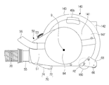
5 is a rear view of the cleaner main body according to an embodiment of the present invention.
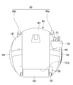
6 is a bottom view of the cleaner main body according to an embodiment of the present invention.
7 is a sectional view taken along the line B-B 'in Fig. 5;
8 is a cross-sectional view taken along line C-C 'of FIG. 5;
9 is a sectional view taken along the line A-A 'in Fig.
10 to 13 are views illustrating a restoration operation of the cleaner main body according to an embodiment of the present invention.
14 is a side view of a cleaner body according to another embodiment of the present invention.
15 is a rear view of the cleaner main body according to another embodiment of the present invention.
16 is a bottom view of the cleaner main body according to another embodiment of the present invention.
17 is a perspective view of a vacuum cleaner according to another embodiment of the present invention.
본 명세서에 기재된 실시예와 도면에 도시된 구성은 개시된 발명의 바람직한 일 예에 불과할 뿐이며, 본 출원의 출원시점에 있어서 본 명세서의 실시예와 도면을 대체할 수 있는 다양한 변형 예들이 있을 수 있다.It is to be understood that both the foregoing general description and the following detailed description of the present invention are exemplary and explanatory only and are not restrictive of the invention, as claimed, and it is to be understood that the invention is not limited to the disclosed embodiments.
또한, 본 명세서의 각 도면에서 제시된 동일한 참조번호 또는 부호는 실질적으로 동일한 기능을 수행하는 부품 또는 구성요소를 나타낸다.In addition, the same reference numerals or signs shown in the respective figures of the present specification indicate components or components performing substantially the same function.
또한, 본 명세서에서 사용한 용어는 실시예를 설명하기 위해 사용된 것으로, 개시된 발명을 제한 및/또는 한정하려는 의도가 아니다. 단수의 표현은 문맥상 명백하게 다르게 뜻하지 않는 한, 복수의 표현을 포함한다. 본 명세서에서, "포함하다" 또는 "가지다" 등의 용어는 명세서상에 기재된 특징, 숫자, 단계, 동작, 구성요소, 부품 또는 이들을 조합한 것이 존재함을 지정하려는 것이지, 하나 또는 그 이상의 다른 특징들이나 숫자, 단계, 동작, 구성요소, 부품 또는 이들을 조합한 것들의 존재 또는 부가 가능성을 미리 배제하지 않는다.Also, the terms used herein are used to illustrate the embodiments and are not intended to limit and / or limit the disclosed invention. The singular expressions include plural expressions unless the context clearly dictates otherwise. In this specification, the terms "comprises" or "having" and the like refer to the presence of stated features, integers, steps, operations, elements, components, or combinations thereof, But do not preclude the presence or addition of one or more features, integers, steps, operations, elements, components, or combinations thereof.
또한, 본 명세서에서 사용한 “제1”, “제2” 등과 같이 서수를 포함하는 용어는 다양한 구성요소들을 설명하는데 사용될 수 있지만, 상기 구성요소들은 상기 용어들에 의해 한정되지는 않으며, 상기 용어들은 하나의 구성요소를 다른 구성요소로부터 구별하는 목적으로만 사용된다. 예를 들어, 본 발명의 권리 범위를 벗어나지 않으면서 제1 구성요소는 제2 구성요소로 명명될 수 있고, 유사하게 제2 구성요소도 제1 구성요소로 명명될 수 있다. “및/또는” 이라는 용어는 복수의 관련된 기재된 항목들의 조합 또는 복수의 관련된 기재된 항목들 중의 어느 항목을 포함한다.It is also to be understood that terms including ordinals such as " first ", " second ", and the like used herein may be used to describe various elements, but the elements are not limited by the terms, It is used only for the purpose of distinguishing one component from another. For example, without departing from the scope of the present invention, the first component may be referred to as a second component, and similarly, the second component may also be referred to as a first component. The term " and / or " includes any combination of a plurality of related listed items or any of a plurality of related listed items.
이하에서는 본 발명에 따른 실시예를 첨부된 도면을 참조하여 상세히 설명한다. Hereinafter, embodiments according to the present invention will be described in detail with reference to the accompanying drawings.
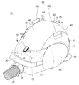
도 1은 본 발명의 일 실시예에 따른 청소기의 사시도이다.1 is a perspective view of a vacuum cleaner according to an embodiment of the present invention.
본 발명의 실시예에 따른 청소기(1)는 본체(30), 헤드유닛(10), 연장관(12), 핸들어셈블리(14)와 호스(20)를 포함할 수 있다.The
헤드유닛(10)에 마련되는 흡입부는 피청소면에 접촉하여 피청소면 상의 이물질을 흡입할 수 있다. 본 발명의 실시예에 따른 진공청소기는 캐니스터 타입(canister type)의 진공청소기일 수 있다.The suction unit provided on the
스틱형상의 연장관(12)은 헤드유닛(10)에 연결된다. 연장관(12)은 수지 또는 금속재질로 구비되고, 헤드유닛(10)과 핸들어셈블리(14)를 연결할 수 있다. 연장관(12)은 헤드유닛(10)과 피봇연결되어, 관절운동하도록 마련될 수 있다.The stick-shaped
핸들어셈블리(14)는 연장관(12)과 호스(20)를 연결하도록 구비된다. 핸들어셈블리(14)는 핸들부(16) 및 조작부(18)가 마련될 수 있다. 사용자는 핸들부(16)를 파지하고 청소할 수 있고, 조작부(18)에 마련된 버튼등을 조작하여 청소기를 온/오프시키거나 흡입강도를 조절하는 등 진공청소기의 기능을 조작할 수 있다.The
호스(20)는 핸들어셈블리(14)와 청소기 본체(30)를 연결한다. 호스(20)는 핸들어셈블리(14)의 자유로운 이동을 위해 유연한 재질을 갖도록 마련될 수 있다. 호스(20)는 청소기 본체(30)의 흡입관(55)과 연결될 수 있다.The
먼지분리장치(22)는 핸들어셈블리(14)에 분리가능하게 마련될 수 있다. 먼지분리장치(22)는 헤드유닛(10)으로부터 유입되는 공기 중 이물질을 걸러낼 수 있도록 마련된다. 본 실시예에서 먼지분리장치(22)는 핸들어셈블리(14)에 마련되어, 흡입되는 공기 중 이물질을 청소기 본체(30)에 앞서서 걸러낸다. 이를 위해 헤드유닛(10)과 연장관(12)을 지나는 공기는 먼지분리장치(22)를 거쳐 호스(20)로 유동할 수 있도록 마련된다. 그러나 먼지분리장치(22)의 배치는 이에 한정하지 않고, 먼지분리장치(22)가 본체(30)에 마련되어 본체(30)에서 걸러지는 구성을 하여도 무방하다.The
헤드유닛(10), 연장관(12), 핸들어셈블리(14), 먼지분리장치(22), 호스(20)와, 청소기본체(30)는 모두 연통되도록 마련될 수 있다. 즉, 헤드유닛(10)으로부터 흡입된 공기는 연장관(12), 핸들어셈블리(14), 먼지분리장치(22), 호스(20)를 지나 청소기본체(30)를 거쳐 외부로 토출될 수 있다.The
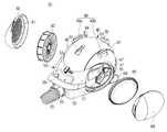
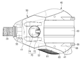
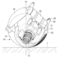
도 2는 본 발명의 일 실시예에 따른 청소기 본체의 사시도, 도 3은 본 발명의 일 실시예에 따른 청소기 본체의 일부 분해사시도, 도 4는 본 발명의 일 실시예에 따른 청소기 본체를 측면에서 본 도면, 도 5는 본 발명의 일 실시예에 따른 청소기 본체를 후방에서 본 도면, 도 6은 본 발명의 일 실시예에 따른 청소기 본체를 하부에서 본 도면이다.FIG. 2 is a perspective view of a cleaner main body according to an embodiment of the present invention, FIG. 3 is a partially exploded perspective view of a cleaner main body according to an embodiment of the present invention, and FIG. 4 is a side view of the cleaner main body according to an embodiment of the present invention. FIG. 5 is a rear view of a cleaner main body according to an embodiment of the present invention, and FIG. 6 is a bottom view of the cleaner main body according to an embodiment of the present invention.
청소기 본체(30)는 사용자가 핸들어셈블리(14)를 이동시키는 경우 호스(20)에 연결되어 뒤따라 이동하도록 구성된다. 청소기 본체(30)의 내부에는 흡입모터(97)를 갖고, 흡입모터(97)에서 발생하는 흡입력으로 공기를 유동시킬 수 있게 된다.The
청소기 본체(30)는 청소작업시에 호스(20)에 의해 이끌려 이동하면서, 장애물에 부딪혀서 뒤집히거나, 이동경로에 따라 뒤집히는 일이 발생하게 된다. 본 발명의 청소기 본체(30)는 이동 중에 균형을 잃고 뒤집히더라도 다시 스스로 원상복귀할 수 있도록 마련된다.The cleaner
청소기 본체(30)는 그 내부에 흡입력을 발생시키는 흡입모터(97)와, 공기가 유동하는 유로(35)가 구성될 수 있다.The cleaner
청소기 본체(30)는 제 1 본체(40)와, 제 2 본체(50)를 포함한다.The cleaner
제 1 본체(40)는 구(球)형의 형상을 가지도록 마련될 수 있다. 그러나 이에 한정되지 않고, 제 1 본체(40)는 구형에 가까운 형상을 가져도 무방하며, 타원형으로 구성되어도 무방하다. 자세하게는 제 1 본체(40)는 상면(43), 양측면(41)이 곡면으로 형성될 수 있다. 제 1 본체(40)의 후면(42)도 곡면으로 형성될 수 있다. 이러한 구성을 통해 제 1 본체(40)는 전체적으로 구형의 형상을 가질 수 있다. The
제 1 본체(40)의 외관이 곡면으로 형성됨으로써, 제 1 본체(40)는 좌우측을 향해 쓰러지거나, 뒤집혀서 상면(43) 또는 후면(42)이 바닥면(F)에 접촉하는 경우에도, 굴러서 다시 원상복귀 할 수 있게 된다.The outer surface of the first
제 2 본체(50)는 제 1 본체(40)의 전방에서 돌출되도록 마련된다. 제 2 본체(50)는 제 1 본체(40)에서 하부로 치우치게 전방으로 돌출될 수 있다.The
제 2 본체(50)는 제 1 본체(40)의 전방에 마련되어, 제 1 본체(40)가 전방으로 회전하는 것을 방지 할 수 있다. 또한 제 2 본체(50)는 구형의 제 1 본체(40)가 안정적으로 이동경로를 따라 이동할 수 있도록 마련된다. The second
제 2 본체(50)는 전방을 향해 갈수록 폭이 좁아지도록 마련될 수 있다. 즉, 제 2 본체(50)는 임의의 제 1 지점에서의 좌우폭보다, 제 1 지점보다 전방에 위치하는 제 2 지점에서의 좌우폭이 더 작도록 마련될 수 있다. 제 2 본체(50)의 양측면(51)은 제 1 본체(40)의 양측면(41)으로부터 연장되도록 마련되므로, 상부에서 보는 경우 대략 삼각형의 형상을 가질 수 있다. 이러한 구성을 통해 본체(30)가 이동경로를 따라 이동하면서 장애물에 부딪히더라도 그 충격을 최소화시킬 수 있게 된다. 이를 위해 도시하지 않았으나 제 2 본체(50)의 양측면(51)에는 완충부재가 마련될 수 있다. 즉, 완충부재가 제 2 본체(50)의 양측면을 덮도록 하여, 장애물에 대한 충격을 흡수할 수 있다.The second
제 2 본체(50)의 양측면(51)이 이루는 각은 한정되지 않으나 0도이상 90도미만으로 형성될 수 있다. 바람직하게는 45도가 될 수 있다.The angle formed by the both side surfaces 51 of the second
제 2 본체(50)는 전방을 향해 갈수록 높이가 낮아지도록 마련될 수 있다. 즉, 제 2 본체(50)는 임의의 제 1 지점에서의 상하높이보다, 제 1 지점보다 전방에 위치하는 제 2 지점에서의 상하높이가 더 작도록 마련될 수 있다. 제 2 본체(50)는 제 1 본체(40)의 상하부로부터 연장되도록 마련되므로, 측부에서 보는 경우 대략 삼각형의 형상을 가질 수 있다. 제 2 본체(50)의 상면(53)과 하부면(52)이 이루는 각은 한정되지 않으나 0도 이상 90도 미만으로 형성될 수 있다. 바람직하게는 60도가 될 수 있다.The second
제 2 본체(50)의 양측면(51)은 제 1 본체(40)의 양측면(41)으로부터 각각 연장형성될 수 있다. 제 2 본체(50)의 양측면(51)은 적어도 일부가 상하방향으로 곡률을 갖는 평면으로 형성될 수 있다. 이러한 구성을 통해 청소기 본체(30)가 횡전(橫轉)하는 경우에 부드럽게 원위치로 복귀 할 수 있게 된다. 또한 본체(30)가 횡전하는 경우 바닥면(F)과 접선(T, 도 10 내지 13 참고) 또는 적어도 2 점이상의 접점을 형성할 수 있게 된다.Both side surfaces 51 of the second
제 2 본체(50)에서 양측면(51) 하부는 곡면으로 형성될 수 있다. 이는 제 1 본체(40)가 곡면 또는 구형의 형상으로 형성되는 것과 대응될 수 있다. 제 2 본체(50)에서 임의의 제 1 지점에서의 양측면(51) 하부에서의 곡률보다, 제 1 지점보다 전방에 배치되는 제 2 지점에서의 양측면(51) 하부에서의 곡률이 크게 형성될 수 있다. 이러한 구성을 통해 본체(30)가 횡전한 상태에서 안정적으로 원위치로 복귀할 수 있게 된다.In the second
본체(30)가 제 1 본체(40)와 같이 구형의 형상으로만 이루어지는 경우, 본체(30)가 횡전(橫轉)하여 본체(30)의 측면이 바닥면(F)에 닿게 되면, 본체(30)는 바닥면(F)과 접점을 형성하게 된다. 이러한 경우 청소기 본체(30)가 이동에 의해 접점의 위치가 계속 변하게 되면서, 무게중심(G)과 접점이 형성하는 모멘트의 방향이 변하게 된다. 그러므로 무게중심(G)이 본체(30)의 중심보다 하부에 위치하여도 균형을 잃고 불안정하게 원위치로 복귀하게 된다.When the
본 실시예에서의 본체(30)는 제 1, 2 본체(40, 50)로 이루어져 있어 본체(30)가 횡전하여 본체(30)의 측면이 바닥면(F)에 닿게 되면, 본체(30)는 바닥면(F)과 접선 또는 적어도 2개 이상의 접점을 형성하게 된다. 이러한 경우 청소기 본체(30)가 이동하더라도 무게중심(G)과 접선 또는 적어도 2개 이상의 접점이 형성하는 모멘트의 방향이 일정하게 되어, 안정적으로 원위치로 복귀하게 된다. The
청소기 본체(30)의 무게중심(G)이 본체(30) 중심보다 전방하부에 위치하게 된다. 청소기 본체(30)가 뒤집어지는 경우 복귀하는 동작 또는 원리에 대해서는 이후 자세하게 설명한다.The center of gravity G of the cleaner
청소기는 청소기 본체(30)의 일측에서 청소기 본체(30)를 옮기기 위한 손잡이(56)를 포함할 수 있다. 손잡이(56)는 청소기 본체(30)의 전방에 마련될 수 있으며, 청소기 본체(30)로부터 연장형성될 수 있다. 본 실시예에서는 손잡이(56)가 청소기 본체(30)의 전방에 마련되나, 그 배치위치는 한정되지 않는다.The cleaner may include a
도 5에서 보듯이, 청소기는 본체(30)의 이동을 위해 회전가능하게 마련되는 적어도 하나의 이동휠(60)을 포함할 수 있다. 이동휠(60)은 하나가 마련될 수도 있으며, 복수개가 나란하게 마련될 수도 있다.As shown in FIG. 5, the vacuum cleaner may include at least one moving
이동휠(60)은 본체(30)의 중심을 따라 배치될 수 있다. 자세하게는 이동휠(60)은 제 1 본체(40)의 중심을 따라 배치될 수 있다. 이동휠(60)은 본체(30)의 중심을 따라 배치되므로, 이동휠(60)의 양측으로 본체(30)의 양측 구성이 배치될 수 있다. 제 1 본체(40)는 이동휠(60)이 지나며, 이동휠(60)이 바닥면(F)과 접촉할 수 있도록, 적어도 일부가 개방된 개구(45a)를 갖는 중앙본체(45)와, 본체(30)의 전진방향을 기준으로 본체(30)를 정면에서 바라볼 때 이동휠(60)의 좌측에 배치되는 좌측본체(46)와, 이동휠(60)의 우측에 배치되는 우측본체(47)를 포함할 수 있다. 이동휠(60)은 중앙본체(45)에 배치되고, 좌우측본체(46, 47)가 이동휠(60)의 좌우측에 배치됨에 따라, 이동휠(60)의 좌우측을 덮어 외부영향에 의해 마모되거나, 손상을 입는 것을 최소화할 수 있다.The moving
이동휠(60)은 본체(30)의 후방에 편심되어 회전하도록 마련될 수 있다. 이동휠(60)은 제 1 본체(40)의 내측면을 따라 배치되며, 그 회전중심(R1)이 제 1 본체(40)의 중심(C1)을 지나도록 마련될 수 있다. 본체(30)는 제 1 본체(40)와, 제 1 본체(40)의 전방으로 돌출되는 제 2 본체(50)를 포함하도록 마련되므로, 이동휠(60)의 회전중심은 본체(30)의 후방으로 치우치게 편심될 수 있다.The moving
이동휠(60)의 너비는 좌측본체(46) 또는 우측본체(47)의 너비보다 크게 형성될 수 있다. 이러한 구성을 통해 본체(30)를 안정적으로 바닥면(F)에 대해 지지할 수 있다.The width of the moving
이동휠(60)은 중앙본체(45)에서 중앙본체(45)의 내측면과 간격을 유지하여 구성되며, 중앙본체(45)의 내측면을 따라 회전할 수 있다. 이동휠(60)의 회전에 대해서는 이후 자세하게 설명한다.The moving
청소기는 이동휠(60)과 인접하게 배치되어, 청소기의 균형을 잡도록 마련되는 보조휠(66)을 포함할 수 있다.The vacuum cleaner may include an
보조휠(66)은 한 쌍이 마련될 수 있으며, 이동휠(60)의 좌우측에 각각 배치될 수 있다. 한 쌍의 보조휠(66)은 각각 좌측본체(46)와, 우측본체(47)에 하나씩 마련될 수 있다. 자세하게는 좌우측본체(47)로부터 후방으로 각각 돌출형성되는 한 쌍의 보조휠지지부(68)가 마련되고, 한 쌍의 보조휠(66)은 한 쌍의 보조휠지지부(68)에 각각 회전가능하게 구성된다. 한 쌍의 보조휠지지부(68)는 본체(30)로부터 후방으로 돌출되어 형성됨에 따라, 본체(30)가 후방으로 회전하는 것을 방지할 수 있게 된다. 또한 한 쌍의 보조휠(66)은 이동휠(60)의 좌우측에서 청소기 본체(30)가 이동시에 균형을 잡도록 마련될 수 있다.The pair of
청소기(1)는 청소기 본체(30)의 이동시 방향전환을 위해 방향전환유닛(70)을 포함할 수 있다. 방향전환유닛(70)은 이동휠(60)의 전방에 위치하여, 청소기 본체(30)의 방향전환시 회전할 수 있도록 마련된다. 자세하게는 방향전환유닛(70)은 제 2 본체(50)의 하부에 마련될 수 있다.The
방향전환유닛(70)은 방향전환플레이트(74)와, 방향전환휠(72)을 포함할 수 있다. 방향전환플레이트(74)는 본체(30)에 대해 회전가능하게 마련되며, 회전축이 청소기 본체(30)의 상하?항으로 형성되도록 마련된다. 즉, 방향전환플레이트(74)는 좌우방향으로 회전할 수 있도록 형성된다. 방향전환휠(72)은 방향전환플레이트(74)와 독립적으로 회전하도록 마련되며, 방향전환플레이트(74)의 하부에 마련되어, 바닥면(F)에 지지되도록 마련된다.The redirecting
본체(30)의 이동시, 본체(30)의 이동방향이 변하게 되면 방향전환휠(72)은 방향전환플레이트(74)와 함께 좌우방향으로 회전하게 되며, 방향전환휠(72)은 제 2 본체(50)를 바닥면(F)에 대해 지지할 수 있게 한다.The
청소기(1)는 본체(30)내부를 지나는 공기가 배출되는 배출구(81)를 포함할 수 있다. 헤드유닛(10)으로부터 흡입되는 공기는 흡입관(55)을 통해 청소기본체(30)로 흡입되며, 내부공기유로(35)를 지나 배출구(81)를 통해 본체(30)의 외부로 배출된다. 배출구(81)는 본체(30)의 좌우측면 중 적어도 어느 하나의 면에 배치될 수 있다. 배출구(81)는 복수의 홀형상으로 마련될 수 있다. 배출구(81)는 배출플레이트(80)에 마련될 수 있다. 배출플레이트(80)는 도 3과 같이 본체(30)로부터 분리가능하게 마련될 수 있다. 배출플레이트(80)는 대략 원형의 형상을 가질 수 있다. 배출플레이트(80)는 곡면으로 형성되어, 제 1, 2 본체(30)의 일부로 구성될 수 있다. 배출플레이트(80)의 내부에는 배기필터(82)가 배치될 수 있다.The
청소기는 필터플레이트(84)를 포함할 수 있다. 필터플레이트(84)는 도 3 과 같이 내부에 분리필터(86)를 교환하기 위해 본체(30)로부터 분리가능하게 마련될 수 있다. 필터플레이트(84)는 배출플레이트(80)의 타측에 배치될 수 있다. 즉, 배출플레이트(80)는 좌, 우측 본체(46, 47) 중 어느 하나에 마련될 수 있고, 필터플레이트(84)는 좌우측 본체(46, 47) 중 다른 하나에 마련될 수 있다. 필터플레이트(84)는 곡면으로 형성되어, 제 1, 2 본체(40, 50)의 일부로서 기능할 수 있다.The vacuum cleaner may include a
본체(30)의 후방에는 청소기에 동력을 전달하는 코드(93)가 인출가능하도록 코드출입구(91)가 마련될 수 있다. 자세하게는 코드출입구(91)는 제 1 본체(40)의 후방에 마련될 수 있다. 코드(93)는 본체(30) 내부의 마련되는 코드릴(90)에 감겨 보관되도록 마련되며, 코드(93)는 코드릴(90)에 의해 코드(93)의 단부에 마련되는 헤드부(94)가 코드출입구(91)에 다다를때까지 본체(30) 내부에 감길 수 있도록 마련된다.A cord inlet /
청소기는 버튼부(49)를 포함할 수 있다. 버튼부(49)는 코드릴버튼(49a)과 전원버튼(49b)을 포함할 수 있다. 버튼부(49)는 본체(30)의 상부에 마련될 수 있으며, 그 배치는 한정되지 않는다. 코드릴버튼(49a)은 조작시 코드릴(90)에 코드(93)가 감길 수 있도록 구성되며, 전원버튼(49b)은 조작시 코드(93)를 통해 본체(30)에 전력을 공급할 수 있도록 마련된다.The cleaner may include a
청소기 본체(30)에는 청소솔꽂이(95)가 마련될 수 있다. 청소솔은 헤드유닛(10) 대신 연장관(12)에 꽂아 사용하며, 이를 청소솔꽂이(95)에 꽂아 보관할 수 있다.The cleaner
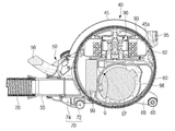
도 7은 도 5의 B-B'의 단면도, 도 8은 도 5의 C-C'의 단면도이다.7 is a cross-sectional view taken along line B-B 'of FIG. 5, and FIG. 8 is a cross-sectional view taken along line C-C' of FIG.
이동휠(60)은 본체(30)의 내측면(45a)을 따라 회전하도록 마련될 수 있다. 자세하게는 이동휠(60)은 본체(30)의 내측면(45a)과 일정간격 이격되어 회전하도록 형성될 수 있다. 이동휠(60)은 중앙본체(45)의 내부에서, 중앙본체(45)의 내측면(45a)과 일정간격 이격되어 회전하도록 마련될 수 있다. 이동휠(60)은 본체(30)의 크기에 비해 크게 형성되므로, 청소기 본체(30)를 안정적으로 이동시킬 수 있게 된다. 또한 이동휠(60)의 내부공간은 청소기 본체(30)의 내부구성들을 배치할 수 있으므로, 공간활용성을 향상시킬 수 있다.The moving
이동휠(60)은 휠회전지지부(62)에 의해 이동휠(60)의 내측면이 지지될 수 있다. 휠회전지지부(62)는 청소기 본체(30)의 내부구성을 감싸는 케이스의 기능도 할 수 있다. 휠회전지지부(62)에는 도 8에서 보는 바와 같이 적어도 하나의 베어링(64)이 마련될 수 있다. 적어도 하나의 베어링(64)은 휠회전지지부(62)에 대해 이동휠(60)이 부드럽게 회전할 수 있도록 구성될 수 있다. 본 실시예에서는 복수의 베어링(64)이 휠회전지지부(62)를 따라 원주방향으로 이격되어 배치되나, 그 배치위치 및 베어링(64)의 개수는 한정되지 않는다.The moving
흡입모터(97)는 본체(30)의 내부에서 흡입력을 발생시키도록 마련된다. 흡입모터(97)는 본체(30)의 내부에서 내부공기유로(35)상에 마련될수 있다. The
흡입모터(97)는 본체(30)의 하부에 마련될 수 있다. 흡입모터(97)가 본체(30)의 하부에 마련됨에 따라 청소기 본체(30)의 무게중심(G)을 본체(30)의 중심보다 하부에 위치하도록 할 수 있다. 흡입모터(97)의 주위로는 흡입모터(97)의 주위를 감싸도록 마련되는 흡입모터 케이스(98)를 포함할 수 있다. 흡입모터 케이스(98)는 내부공기유로의 일부를 형성할 수 있다.The
제어장치(99)는 흡입모터(97)의 전방에 배치될 수 있다. 제어장치(99) 또한 흡입모터(97)와 함께 본체(30)의 하부측에 배치됨에 따라 청소기 본체(30)의 무게중심(G)을 본체(30)의 중심보다 하부에 위치하도록 할 수 있다.The
청소기는 코드릴(90)을 포함할 수 있다.The cleaner may include a cord drill (90).
코드릴(90)은 청소기로 동력을 전달하는 코드(93)가 감기도록 구성된다. 코드릴(90)은 회전가능하게 마련되며, 그 회전에 의해 코드(93)가 코드릴(90)의 외주면을 따라 감길 수 있게 된다.The cord drill (90) is configured to wind a cord (93) that transmits power to the cleaner. The
도 9는 도 4의 A-A'의 단면도이다.9 is a cross-sectional view taken along line A-A 'in Fig.
본체(30)의 내부에는 흡입관(55)으로부터 시작되는 내부공기유로가 마련될 수 있다. 내부공기유로는 분리필터(86), 흡입모터(97), 배기필터(82)를 지나 배출구(81)로 연결될 수 있다.An internal air passage starting from the
분리필터(86)는 필터플레이트(84)의 내측에 배치될 수 있으며, 배기필터(82)는 배기플레이트의 내측에 배치될 수 있다. 분리필터(86)와 배기필터(82)는 내부공기유로(35)를 통해 이동하는 공기 중의 이물질을 걸러내도록 마련된다.The
분리필터(86)와 배기필터(82)는 각각, 필터플레이트(84)와 배기플레이트를 본체(30)로부터 분리시켜 외부로 노출시킬 수 있으며, 이를 통해 필터의 교환이 가능하게 된다.The
이하는 청소기 본체(30)가 스스로 원위치로 복귀하는 동작에 관하여 설명한다.Hereinafter, an operation in which the cleaner
도 10 내지 13은 본 발명의 일 실시예에 따른 청소기 본체의 횡전(橫轉)에 따른 복원동작에 관한 도면이다.10 to 13 are diagrams illustrating restoration operations of the cleaner main body according to an embodiment of the present invention.
도 10은 청소기 본체(30)가 옆으로 회전하는 경우이며, 도 11은 도 10에서 기울어진 청소기 본체(30)를 본체(30) 정면에서 바라본 도면이다. 도 11에서 T1a는 복수의 접점 또는 접선(T1) 중에 청소기 본체를 본체(30) 정면에서 바라본 각도에서의 임의의 접점(T1a)을 나타낸 것이다. 본체(30)는 제 1, 2 본체(40, 50)의 측면 중 바닥면(F)과 접선 또는 적어도 2개 이상의 접점을 형성하며, 바닥면(F)과 닿게 된다. 본체(30)의 무게중심(G)은 접선 또는 적어도 2개 이상의 접점으로부터의 법선이 형성하는 가상면(P1)과, 본체(30)의 중심선(C)과의 교점(A)보다 본체(30)의 하부에 위치하게 된다. 이에 의해, 본체(30)에는 무게중심(G)에서의 발생하는 모멘트(M1)가 발생하게 되고, 화살표방향으로 제 1, 2 본체(30)에 형성되는 곡면을 따라 본체(30)가 회전하여 이동휠(60)이 바닥면(F)에 닿아 원위치로 복귀하게 된다.10 is a side view of the cleaner
도 12는 청소기 본체(30)가 도 10의 경우보다 옆으로 더 회전한 경우이며, 도 13은 도 12에서 기울어진 청소기 본체(30)를 본체(30) 정면에서 바라본 도면이다. 도 13에서 T2a는 복수의 접점 또는 접선(T2) 중에 청소기 본체를 본체(30) 정면에서 바라본 각도에서의 임의의 접점(T1a)을 나타낸 것이다. 본체(30)는 제 1, 2 본체(40, 50)의 측면 중 바닥면(F)과 접선 또는 적어도 2개 이상의 접점을 형성하며, 바닥면(F)과 닿게 된다. 본체(30)의 무게중심(G)은 접선 또는 적어도 2개 이상의 접점으로부터의 법선이 형성하는 가상면(P2)과, 본체(30)의 중심선(C)과의 교점(B)보다 하부에 위치하게 된다. 이에 의해, 본체(30)에는 무게중심(G)에서의 발생하는 모멘트(M2)가 발생하게 되고, 화살표방향으로 제 1, 2 본체(30)에 형성되는 곡면을 따라 본체(30)가 회전하여 이동휠(60)이 바닥면(F)에 닿아 원위치로 복귀하게 된다.12 is a view showing a case where the cleaner
본체(30)가 상하가 반전된 경우에 대해서는 도시하지 않았으나, 본체(30)의 상부는 곡면으로 형성되므로 좌우측 어느 방향으로 회전하게 되고, 도 10 또는 도 12에서의 청소기 본체(30)와 같은 위치로 변하면서 본체(30)가 원상복귀하게 된다.Since the upper portion of the
이하는 본 발명의 다른 실시예에 따른 청소기에 관하여 설명한다.Hereinafter, a vacuum cleaner according to another embodiment of the present invention will be described.
상기 설명과 중복되는 구성에 대해서는 설명을 생략한다.Explanations of configurations overlapping with the above description are omitted.
도 14는 본 발명의 다른 실시예에 따른 청소기 본체를 측면에서 본 도면, 도 15는 본 발명의 다른 실시예에 따른 청소기 본체를 후방에서 본 도면, 도 16은 본 발명의 다른 실시예에 따른 청소기 본체를 하부에서 본 도면이다.FIG. 14 is a side view of a cleaner body according to another embodiment of the present invention, FIG. 15 is a rear view of the cleaner body according to another embodiment of the present invention, FIG. 16 is a perspective view of a cleaner according to another embodiment of the present invention, Fig.
이동휠(160)은 본체(30)의 후방에 마련될 수 있다. 자세하게는 제 1 본체(140)의 후방에 마련될 수 있다. 이동휠(160)의 회전중심(R2)은 제 1 본체(140)의 후방하부에 위치할 수 있으며, 이동휠(160)의 양측으로 본체의 양측구성이 배치될 수 있다. 제 1 본체(140)는 이동휠(160)이 지나며, 이동휠(160)이 바닥면(F)과 접촉할 수 있도록, 적어도 일부가 개방된 개구(145a)를 갖는 중앙본체(145)와, 본체(30)의 전진방향을 기준으로 본체를 정면에서 바라볼 때 이동휠(160)의 좌측에 배치되는 좌측본체(146)와, 이동휠(160)의 우측에 배치되는 우측본체(147)를 포함할 수 있다. 이동휠(160)은 중앙본체(145)에 배치되고, 좌우측본체(146, 147)는 이동휠(160)의 좌우측에 배치됨에 따라, 이동휠(160)의 좌우측을 덮어 외부영향에 의해 마모되거나, 손상을 입는 것을 최소화시킬 수 있다.The moving
이동휠(160)은 본체(30)의 후방에 편심되어 회전하도록 마련될 수 있다. 이동휠(160)은 제 1 본체(140)의 후방하부에 배치되며, 그 회전중심(R2)는 제 1 본체(140)의 후방하부에 위치하도록 마련될수 있다. 이에 따라 이동휠(160)이 본체(30)에서 차지하는 공간을 최소화시킬 수 있으며, 이동휠(160)의 전방에 흡입모터(97)가 마련됨에 따라 본체(30)의 무게중심(G2)을 본체(30)의 중심보다 하부에 위치하도록 할 수 있다. 또한, 이동휠(160)이 제 1 본체(140)의 후방하부에 위치함에 따라 본체(30) 내부의 활용공간이 상대적으로 넓어지게 될 수 있다. 이로서, 본체(30) 내부에서 이동휠(160)의 전방으로 흡입모터(97), 제어장치, 먼지분리장치등을 배치함으로서, 청소기 본체의 무게중심을 본체의 중심보다 하부에 위치하도록 할 수 있다.The moving
이하는 본 발명의 다른 실시예에 따른 청소기에 관하여 설명한다.Hereinafter, a vacuum cleaner according to another embodiment of the present invention will be described.
상기 설명과 중복되는 구성에 대해서는 설명을 생략한다.Explanations of configurations overlapping with the above description are omitted.
도 17은 본 발명의 또 다른 실시예에 따른 청소기의 사시도이다.본 실시예에서 먼지분리장치(122)는 청소기 본체(30)에 구성될 수 있다.17 is a perspective view of a vacuum cleaner according to another embodiment of the present invention. In this embodiment, the
먼지분리장치(122)는 헤드유닛(10)으로부터 유입되는 공기 중 이물질을 걸러낼 수 있도록 마련된다. 본 실시예에서 먼지분리장치(122)는 청소기본체(30)에 마련되어, 흡입관(55)으로 흡입되는 공기 중의 이물질을 청소기 본체(30)에 앞서서 걸러낸다. 이를 위해 헤드유닛(10)과 연장관(12)을 지나는 공기는 먼지분리장치(122)를 거쳐 호스(20)로 유동할 수 있도록 마련된다.The
먼지분리장치(122)는 도면과 같이 청소기 본체(30)의 전방에 마련되나, 이에 한정되지 않고, 청소기 본체(30)의 내부에 마련될 수 있다.The
이상에서는 특정의 실시예에 대하여 도시하고 설명하였다. 그러나, 상기한 실시예에만 한정되지 않으며, 발명이 속하는 기술분야에서 통상의 지식을 가진 자라면 이하의 청구범위에 기재된 발명의 기술적 사상의 요지를 벗어남이 없이 얼마든지 다양하게 변경 실시할 수 있을 것이다.The foregoing has shown and described specific embodiments. However, it should be understood that the present invention is not limited to the above-described embodiment, and various changes and modifications may be made without departing from the technical idea of the present invention described in the following claims .
1 : 청소기
10 : 헤드유닛
12 : 연장관
14 : 핸들어셈블리
20 : 호스
30 : 본체
40 : 제 1 본체
45 : 중앙본체
46 : 좌측본체
47 : 우측본체
50 : 제 2 본체
60 : 이동휠
66 : 보조휠
80 : 배출플레이트
84 : 필터플레이트
90 : 코드릴
97 : 흡입모터1: cleaner 10: head unit
12: extension tube 14: handle assembly
20: Hose 30: Body
40: first body 45: central body
46: left main body 47: right main body
50: second body 60: moving wheel
66: Auxiliary wheel 80: Discharge plate
84: Filter plate 90:
97: Suction motor
Claims (21)
구형으로 형성되는 제 1 본체;
상기 제 1 본체의 전방으로부터 돌출되도록 마련되되, 제 1 지점에서의 폭보다 상기 제 1 지점보다 전방에 위치하는 제 2 지점에서의 폭이 작도록 돌출되는 제 2 본체;를 포함하는 청소기.A cleaner main body;
A first body formed in a spherical shape;
And a second body protruding from the front of the first body so that a width at a second point located forward of the first point is smaller than a width at the first point.
상기 제 2 본체의 양측면은,
상기 제 1 본체의 양측면으로부터 각각 연장형성되도록 마련되는 청소기.The method according to claim 1,
Side surfaces of the second main body,
Wherein the first and second bodies are formed to extend from both sides of the first body.
상기 제 2 본체의 양측면은,
적어도 일부가 상하방향으로 곡률을 갖는 평면으로 형성되는 청소기.The method according to claim 1,
Side surfaces of the second main body,
Wherein at least a part of the cleaner is formed into a plane having a curvature in an up-and-down direction.
상기 제 2 본체는 상기 제 1 본체로부터 하부로 치우치도록 전방을 향해 돌출형성되는 청소기.The method according to claim 1,
And the second main body is protruded forward so as to be deviated downward from the first main body.
상기 제 2 본체는 상기 제 1 지점에서의 높이보다 상기 제 2 지점에서의 높이가 작도록 돌출되는 청소기.The method according to claim 1,
Wherein the second body is protruded such that the height at the second point is smaller than the height at the first point.
상기 제 2 본체는,
양측면의 하부가 곡면으로 형성되는 청소기.The method according to claim 1,
And the second body includes:
Wherein the lower portions of both sides are formed as curved surfaces.
상기 제 2 본체는,
상기 제 1 지점에서의 제 2 본체 양측면 하부에서의 곡률보다, 상기 제 1 지점보다 전방에 마련되는 상기 제 2 지점에서의 제 2 본체 양측면 하부에서의 곡률이 더 크도록 마련되는 청소기.The method according to claim 1,
And the second body includes:
Wherein a curvature at both sides of both sides of the second body at the second point, which is provided in front of the first point, is larger than a curvature at both sides of the second body at the first point.
상기 제 1 본체의 내주면을 따라 회전하며, 상기 본체의 이동을 위해 회전가능하게 마련되는 이동휠;을 더 포함하는 청소기.The method according to claim 1,
And a moving wheel that rotates along an inner circumferential surface of the first body and is rotatably provided for movement of the body.
상기 이동휠은,
상기 본체의 중앙에 배치되도록 구성되는 청소기.9. The method of claim 8,
The moving wheel
And is disposed in the center of the main body.
상기 제 1 본체는,
그 내측에 상기 이동휠이 배치되는 중앙본체;
상기 중앙본체의 좌우측에 마련되는 좌우본체;를 포함하는 청소기.9. The method of claim 8,
The first body includes:
A central body in which the moving wheel is disposed;
And left and right main bodies provided on left and right sides of the center body.
상기 중앙본체는,
상기 이동휠의 적어도 일부가 바닥면에 노출되도록 개방되는 청소기.11. The method of claim 10,
Wherein the central body comprises:
Wherein at least a portion of the moving wheel is opened to expose the floor surface.
상기 이동휠의 양측에 마련되되, 상기 본체로부터 후방으로 돌출되어 배치되는 한 쌍의 보조휠;을 더 포함하는 청소기.9. The method of claim 8,
And a pair of auxiliary wheels provided on both sides of the moving wheel, the pair of auxiliary wheels protruding rearward from the main body.
상기 제 2 본체의 하부에 마련되되, 상기 본체의 방향전환을 위해 좌우방향으로 회전가능하게 마련되는 방향전환유닛;을 더 포함하는 청소기.9. The method of claim 8,
And a direction switching unit provided at a lower portion of the second body, the direction switching unit being rotatable in the left-right direction for changing the direction of the main body.
상기 본체는,
상기 제 1 본체의 양 측부 중 적어도 어느 하나에는 상기 본체로 흡입되는 공기가 배출되는 배출구가 마련되는 배출플레이트;를 더 포함하고,
상기 흡입구의 내측에 마련되어 유동하는 공기를 필터링하는 배기필터;를 더 포함하는 청소기.The method according to claim 1,
The main body includes:
And at least one of both side portions of the first body further includes a discharge plate provided with a discharge port through which air sucked into the body is discharged,
And an exhaust filter provided inside the suction port to filter the air that flows.
상기 배출플레이트는 상기 본체로부터 분리가능하고,
상기 배기필터는 상기 배출플레이트가 분리된 공간을 통해 분리가능하게 마련되는 청소기.15. The method of claim 14,
The discharge plate being detachable from the body,
Wherein the exhaust filter is detachably provided through the separated space.
상기 본체의 중앙에서 상기 본체의 이동을 위해 회전가능하게 마련되되, 상기 본체의 내주면을 따라 회전하도록 구성되는 적어도 하나의 이동휠;을 더 포함하는 청소기.A cleaner main body;
And at least one moving wheel rotatable for movement of the main body in the center of the main body, the at least one moving wheel being configured to rotate along an inner circumferential surface of the main body.
상기 본체는,
구형으로 형성되는 제 1 본체;를 포함하고,
상기 적어도 하나의 이동휠은,
상기 제 1 본체의 내주면을 따라 마련되는 청소기.17. The method of claim 16,
The main body includes:
And a first body formed in a spherical shape,
Wherein the at least one moving wheel comprises:
And is disposed along an inner circumferential surface of the first body.
상기 제 1 본체는,
그 내측에 상기 이동휠이 배치되는 중앙본체;
상기 중앙본체의 좌우측에 마련되는 좌우본체;를 포함하는 청소기.18. The method of claim 17,
The first body includes:
A central body in which the moving wheel is disposed;
And left and right main bodies provided on left and right sides of the center body.
상기 중앙본체는,
상기 이동휠의 적어도 일부가 바닥면에 노출되도록 개방되게 마련되는 청소기.19. The method of claim 18,
Wherein the central body comprises:
Wherein at least a part of the moving wheel is opened to be exposed on the floor surface.
상기 본체는,
상기 제 1 본체의 전방으로부터 돌출되도록 마련되되, 제 1 지점에서의 폭보다 상기 제 1 지점보다 전방에 위치하는 제 2 지점에서의 폭이 작도록 돌출되는 제 2 본체;를 더 포함하는 청소기.18. The method of claim 17,
The main body includes:
And a second body protruding from the front of the first body so as to have a smaller width at a second point located forward than the first point than a width at the first point.
상기 적어도 하나의 이동휠은,
회전방향으로 구획되어, 나란하게 회전하는 복수의 이동휠;을 포함하는 청소기.17. The method of claim 16,
Wherein the at least one moving wheel comprises:
And a plurality of moving wheels divided in a rotating direction and rotating in parallel.
Priority Applications (6)
| Application Number | Priority Date | Filing Date | Title |
|---|---|---|---|
| KR1020160014744A KR102467328B1 (en) | 2016-02-05 | 2016-02-05 | Cleaner |
| US16/074,929 US11006794B2 (en) | 2016-02-05 | 2017-02-03 | Cleaner |
| EP17747780.9A EP3395222B1 (en) | 2016-02-05 | 2017-02-03 | Cleaner |
| CN201780010040.6A CN108601492B (en) | 2016-02-05 | 2017-02-03 | Vacuum cleaner |
| AU2017216046A AU2017216046B2 (en) | 2016-02-05 | 2017-02-03 | Cleaner |
| PCT/KR2017/001195 WO2017135735A1 (en) | 2016-02-05 | 2017-02-03 | Cleaner |
Applications Claiming Priority (1)
| Application Number | Priority Date | Filing Date | Title |
|---|---|---|---|
| KR1020160014744A KR102467328B1 (en) | 2016-02-05 | 2016-02-05 | Cleaner |
Publications (2)
| Publication Number | Publication Date |
|---|---|
| KR20170093397A true KR20170093397A (en) | 2017-08-16 |
| KR102467328B1 KR102467328B1 (en) | 2022-11-16 |
Family
ID=59500405
Family Applications (1)
| Application Number | Title | Priority Date | Filing Date |
|---|---|---|---|
| KR1020160014744A KR102467328B1 (en) | 2016-02-05 | 2016-02-05 | Cleaner |
Country Status (6)
| Country | Link |
|---|---|
| US (1) | US11006794B2 (en) |
| EP (1) | EP3395222B1 (en) |
| KR (1) | KR102467328B1 (en) |
| CN (1) | CN108601492B (en) |
| AU (1) | AU2017216046B2 (en) |
| WO (1) | WO2017135735A1 (en) |
Families Citing this family (1)
| Publication number | Priority date | Publication date | Assignee | Title |
|---|---|---|---|---|
| DE102020122669A1 (en) * | 2020-08-31 | 2022-03-03 | Miele & Cie. Kg | Bagless vacuum cleaner |
Citations (4)
| Publication number | Priority date | Publication date | Assignee | Title |
|---|---|---|---|---|
| JPH07308279A (en) * | 1994-05-12 | 1995-11-28 | Electrolux Corp | Vacuum cleaner |
| KR200344840Y1 (en) * | 2003-12-11 | 2004-03-19 | 엘지전자 주식회사 | A fixing structure of exhaust filter in vacuum cleaner |
| JP2005160814A (en) * | 2003-12-03 | 2005-06-23 | Sharp Corp | Vacuum cleaner |
| KR100702733B1 (en) * | 2000-03-01 | 2007-04-03 | 마츠시타 덴끼 산교 가부시키가이샤 | Electric vacuum cleaner |
Family Cites Families (6)
| Publication number | Priority date | Publication date | Assignee | Title |
|---|---|---|---|---|
| GB2452549B (en) * | 2007-09-08 | 2012-03-21 | Dyson Technology Ltd | A surface treating appliance |
| GB2474473B (en) | 2009-10-15 | 2013-10-23 | Dyson Technology Ltd | A surface treating appliance |
| GB2484121B (en) * | 2010-09-30 | 2014-10-22 | Dyson Technology Ltd | A vacuum cleaning appliance |
| GB2487397B (en) * | 2011-01-20 | 2014-12-03 | Dyson Technology Ltd | A cylinder vacuum cleaner |
| GB2503253B (en) * | 2012-06-20 | 2014-10-15 | Dyson Technology Ltd | A cleaning appliance |
| KR101842129B1 (en) * | 2016-05-17 | 2018-03-26 | 엘지전자 주식회사 | Cleaner |
-
2016
- 2016-02-05 KR KR1020160014744A patent/KR102467328B1/en active IP Right Grant
-
2017
- 2017-02-03 US US16/074,929 patent/US11006794B2/en active Active
- 2017-02-03 CN CN201780010040.6A patent/CN108601492B/en active Active
- 2017-02-03 EP EP17747780.9A patent/EP3395222B1/en active Active
- 2017-02-03 WO PCT/KR2017/001195 patent/WO2017135735A1/en active Application Filing
- 2017-02-03 AU AU2017216046A patent/AU2017216046B2/en active Active
Patent Citations (4)
| Publication number | Priority date | Publication date | Assignee | Title |
|---|---|---|---|---|
| JPH07308279A (en) * | 1994-05-12 | 1995-11-28 | Electrolux Corp | Vacuum cleaner |
| KR100702733B1 (en) * | 2000-03-01 | 2007-04-03 | 마츠시타 덴끼 산교 가부시키가이샤 | Electric vacuum cleaner |
| JP2005160814A (en) * | 2003-12-03 | 2005-06-23 | Sharp Corp | Vacuum cleaner |
| KR200344840Y1 (en) * | 2003-12-11 | 2004-03-19 | 엘지전자 주식회사 | A fixing structure of exhaust filter in vacuum cleaner |
Also Published As
| Publication number | Publication date |
|---|---|
| EP3395222B1 (en) | 2021-09-15 |
| EP3395222A1 (en) | 2018-10-31 |
| CN108601492B (en) | 2021-04-20 |
| AU2017216046A1 (en) | 2018-08-09 |
| US11006794B2 (en) | 2021-05-18 |
| CN108601492A (en) | 2018-09-28 |
| US20190029481A1 (en) | 2019-01-31 |
| EP3395222A4 (en) | 2019-01-16 |
| WO2017135735A1 (en) | 2017-08-10 |
| KR102467328B1 (en) | 2022-11-16 |
| AU2017216046B2 (en) | 2021-11-11 |
Similar Documents
| Publication | Publication Date | Title |
|---|---|---|
| CN101219037B (en) | Surface treating appliance | |
| KR102082746B1 (en) | Vacuum cleaner | |
| US7950102B2 (en) | Upright vacuum cleaner having steering unit | |
| JP4811689B2 (en) | Cleaning appliance | |
| KR101472770B1 (en) | Cleaner Apparatus | |
| US10799080B2 (en) | Cleaner | |
| KR102372897B1 (en) | Cleaner | |
| JP2010201170A (en) | Floor tool | |
| KR102083800B1 (en) | Vacuum cleaner | |
| KR102308483B1 (en) | Cleaner head and vacuum cleaner having the same | |
| KR20170093397A (en) | Cleaner | |
| JP2015198891A (en) | Suction port body and vacuum cleaner | |
| JP6623114B2 (en) | Vacuum cleaner suction tool and vacuum cleaner including the same | |
| JP2002143047A (en) | Suction nozzle for floor for vacuum cleaner | |
| KR20050108551A (en) | A suction nozzle for vacuum cleaner | |
| JP6519291B2 (en) | Electric vacuum cleaner | |
| JP2017136218A (en) | Autonomous travel type vacuum cleaner | |
| CN109843136B (en) | Suction tool and electric dust collector | |
| JP2013208161A (en) | Vacuum cleaner | |
| JP2023173093A (en) | Suction port body and vacuum cleaner including the same | |
| KR0148946B1 (en) | Suction brush of a vacuum cleaner | |
| JP2007151730A (en) | Vacuum cleaner | |
| JP2000354573A (en) | Vacuum cleaner nozzle body and vacuum cleaner using the same | |
| JP2007135967A (en) | Vacuum cleaner | |
| JP2013031546A (en) | Suction port body and vacuum cleaner |
Legal Events
| Date | Code | Title | Description |
|---|---|---|---|
| A201 | Request for examination | ||
| E902 | Notification of reason for refusal | ||
| E701 | Decision to grant or registration of patent right |