KR20170091083A - Compact heads-up display system - Google Patents
Compact heads-up display system Download PDFInfo
- Publication number
- KR20170091083A KR20170091083A KR1020177004514A KR20177004514A KR20170091083A KR 20170091083 A KR20170091083 A KR 20170091083A KR 1020177004514 A KR1020177004514 A KR 1020177004514A KR 20177004514 A KR20177004514 A KR 20177004514A KR 20170091083 A KR20170091083 A KR 20170091083A
- Authority
- KR
- South Korea
- Prior art keywords
- screen
- image
- light
- housing
- coupler
- Prior art date
Links
- 230000008878 coupling Effects 0.000 claims abstract description 6
- 238000010168 coupling process Methods 0.000 claims abstract description 6
- 238000005859 coupling reaction Methods 0.000 claims abstract description 6
- 238000000034 method Methods 0.000 claims description 81
- 238000004891 communication Methods 0.000 claims description 27
- 230000004044 response Effects 0.000 claims description 27
- 238000000576 coating method Methods 0.000 claims description 25
- 239000011248 coating agent Substances 0.000 claims description 22
- 239000000463 material Substances 0.000 claims description 22
- 239000011162 core material Substances 0.000 claims description 15
- 239000003351 stiffener Substances 0.000 claims description 13
- 238000012937 correction Methods 0.000 claims description 5
- 229910000838 Al alloy Inorganic materials 0.000 claims description 4
- 230000003213 activating effect Effects 0.000 claims 3
- 238000005452 bending Methods 0.000 claims 1
- 238000004381 surface treatment Methods 0.000 claims 1
- 230000003287 optical effect Effects 0.000 description 37
- 230000006870 function Effects 0.000 description 32
- 230000008569 process Effects 0.000 description 24
- 230000008901 benefit Effects 0.000 description 8
- 230000033001 locomotion Effects 0.000 description 8
- 238000012545 processing Methods 0.000 description 7
- 229920003023 plastic Polymers 0.000 description 6
- 230000000007 visual effect Effects 0.000 description 6
- 238000009434 installation Methods 0.000 description 5
- 239000004033 plastic Substances 0.000 description 5
- 229910052782 aluminium Inorganic materials 0.000 description 4
- XAGFODPZIPBFFR-UHFFFAOYSA-N aluminium Chemical compound [Al] XAGFODPZIPBFFR-UHFFFAOYSA-N 0.000 description 4
- 238000010586 diagram Methods 0.000 description 4
- 229910052751 metal Inorganic materials 0.000 description 4
- 239000002184 metal Substances 0.000 description 4
- 239000000853 adhesive Substances 0.000 description 3
- 230000001070 adhesive effect Effects 0.000 description 3
- 230000004075 alteration Effects 0.000 description 3
- 238000013459 approach Methods 0.000 description 3
- 230000000903 blocking effect Effects 0.000 description 3
- 230000008859 change Effects 0.000 description 3
- 238000001514 detection method Methods 0.000 description 3
- 230000000694 effects Effects 0.000 description 3
- 229920001971 elastomer Polymers 0.000 description 3
- NJPPVKZQTLUDBO-UHFFFAOYSA-N novaluron Chemical compound C1=C(Cl)C(OC(F)(F)C(OC(F)(F)F)F)=CC=C1NC(=O)NC(=O)C1=C(F)C=CC=C1F NJPPVKZQTLUDBO-UHFFFAOYSA-N 0.000 description 3
- 239000004417 polycarbonate Substances 0.000 description 3
- 229920000515 polycarbonate Polymers 0.000 description 3
- 238000003860 storage Methods 0.000 description 3
- OAICVXFJPJFONN-UHFFFAOYSA-N Phosphorus Chemical compound [P] OAICVXFJPJFONN-UHFFFAOYSA-N 0.000 description 2
- 230000015572 biosynthetic process Effects 0.000 description 2
- 239000003086 colorant Substances 0.000 description 2
- 230000007423 decrease Effects 0.000 description 2
- 238000013461 design Methods 0.000 description 2
- 230000009977 dual effect Effects 0.000 description 2
- 210000003811 finger Anatomy 0.000 description 2
- 239000011521 glass Substances 0.000 description 2
- 238000005286 illumination Methods 0.000 description 2
- 238000004519 manufacturing process Methods 0.000 description 2
- 230000013011 mating Effects 0.000 description 2
- 238000007781 pre-processing Methods 0.000 description 2
- 230000000750 progressive effect Effects 0.000 description 2
- 210000001747 pupil Anatomy 0.000 description 2
- 238000007788 roughening Methods 0.000 description 2
- 239000005060 rubber Substances 0.000 description 2
- 230000000087 stabilizing effect Effects 0.000 description 2
- 238000006467 substitution reaction Methods 0.000 description 2
- XUIMIQQOPSSXEZ-UHFFFAOYSA-N Silicon Chemical compound [Si] XUIMIQQOPSSXEZ-UHFFFAOYSA-N 0.000 description 1
- 241000237983 Trochidae Species 0.000 description 1
- 230000002745 absorbent Effects 0.000 description 1
- 239000002250 absorbent Substances 0.000 description 1
- 239000011358 absorbing material Substances 0.000 description 1
- 230000009471 action Effects 0.000 description 1
- 239000006117 anti-reflective coating Substances 0.000 description 1
- 238000000149 argon plasma sintering Methods 0.000 description 1
- 230000005540 biological transmission Effects 0.000 description 1
- 230000004397 blinking Effects 0.000 description 1
- 230000001413 cellular effect Effects 0.000 description 1
- 235000019504 cigarettes Nutrition 0.000 description 1
- 238000010276 construction Methods 0.000 description 1
- 239000013078 crystal Substances 0.000 description 1
- 239000000806 elastomer Substances 0.000 description 1
- 230000007613 environmental effect Effects 0.000 description 1
- 239000010408 film Substances 0.000 description 1
- 238000001914 filtration Methods 0.000 description 1
- 239000011888 foil Substances 0.000 description 1
- 210000003128 head Anatomy 0.000 description 1
- 230000001939 inductive effect Effects 0.000 description 1
- 238000002955 isolation Methods 0.000 description 1
- ZLNQQNXFFQJAID-UHFFFAOYSA-L magnesium carbonate Chemical compound [Mg+2].[O-]C([O-])=O ZLNQQNXFFQJAID-UHFFFAOYSA-L 0.000 description 1
- 238000005259 measurement Methods 0.000 description 1
- 230000007246 mechanism Effects 0.000 description 1
- 150000002739 metals Chemical class 0.000 description 1
- 238000012986 modification Methods 0.000 description 1
- 230000004048 modification Effects 0.000 description 1
- 239000002991 molded plastic Substances 0.000 description 1
- 230000008447 perception Effects 0.000 description 1
- 230000002093 peripheral effect Effects 0.000 description 1
- 235000013550 pizza Nutrition 0.000 description 1
- 239000002985 plastic film Substances 0.000 description 1
- 229920006255 plastic film Polymers 0.000 description 1
- 229920001296 polysiloxane Polymers 0.000 description 1
- 238000002310 reflectometry Methods 0.000 description 1
- 230000000717 retained effect Effects 0.000 description 1
- 239000004065 semiconductor Substances 0.000 description 1
- 238000000926 separation method Methods 0.000 description 1
- 238000007493 shaping process Methods 0.000 description 1
- 229910052710 silicon Inorganic materials 0.000 description 1
- 239000010703 silicon Substances 0.000 description 1
- 238000004088 simulation Methods 0.000 description 1
- 230000005236 sound signal Effects 0.000 description 1
- 230000007480 spreading Effects 0.000 description 1
- 238000003892 spreading Methods 0.000 description 1
- 230000006641 stabilisation Effects 0.000 description 1
- 238000011105 stabilization Methods 0.000 description 1
- 239000010935 stainless steel Substances 0.000 description 1
- 229910001220 stainless steel Inorganic materials 0.000 description 1
- 239000000758 substrate Substances 0.000 description 1
- 238000003786 synthesis reaction Methods 0.000 description 1
- 230000002277 temperature effect Effects 0.000 description 1
- 238000012360 testing method Methods 0.000 description 1
- 239000010409 thin film Substances 0.000 description 1
- 210000003813 thumb Anatomy 0.000 description 1
- 230000007704 transition Effects 0.000 description 1
- 238000002834 transmittance Methods 0.000 description 1
- 239000012780 transparent material Substances 0.000 description 1
Images


Classifications
-
- G—PHYSICS
- G02—OPTICS
- G02B—OPTICAL ELEMENTS, SYSTEMS OR APPARATUS
- G02B27/00—Optical systems or apparatus not provided for by any of the groups G02B1/00 - G02B26/00, G02B30/00
- G02B27/01—Head-up displays
- G02B27/0101—Head-up displays characterised by optical features
-
- B—PERFORMING OPERATIONS; TRANSPORTING
- B60—VEHICLES IN GENERAL
- B60K—ARRANGEMENT OR MOUNTING OF PROPULSION UNITS OR OF TRANSMISSIONS IN VEHICLES; ARRANGEMENT OR MOUNTING OF PLURAL DIVERSE PRIME-MOVERS IN VEHICLES; AUXILIARY DRIVES FOR VEHICLES; INSTRUMENTATION OR DASHBOARDS FOR VEHICLES; ARRANGEMENTS IN CONNECTION WITH COOLING, AIR INTAKE, GAS EXHAUST OR FUEL SUPPLY OF PROPULSION UNITS IN VEHICLES
- B60K35/00—Instruments specially adapted for vehicles; Arrangement of instruments in or on vehicles
- B60K35/20—Output arrangements, i.e. from vehicle to user, associated with vehicle functions or specially adapted therefor
- B60K35/21—Output arrangements, i.e. from vehicle to user, associated with vehicle functions or specially adapted therefor using visual output, e.g. blinking lights or matrix displays
- B60K35/23—Head-up displays [HUD]
-
- B—PERFORMING OPERATIONS; TRANSPORTING
- B60—VEHICLES IN GENERAL
- B60K—ARRANGEMENT OR MOUNTING OF PROPULSION UNITS OR OF TRANSMISSIONS IN VEHICLES; ARRANGEMENT OR MOUNTING OF PLURAL DIVERSE PRIME-MOVERS IN VEHICLES; AUXILIARY DRIVES FOR VEHICLES; INSTRUMENTATION OR DASHBOARDS FOR VEHICLES; ARRANGEMENTS IN CONNECTION WITH COOLING, AIR INTAKE, GAS EXHAUST OR FUEL SUPPLY OF PROPULSION UNITS IN VEHICLES
- B60K35/00—Instruments specially adapted for vehicles; Arrangement of instruments in or on vehicles
- B60K35/50—Instruments characterised by their means of attachment to or integration in the vehicle
-
- B—PERFORMING OPERATIONS; TRANSPORTING
- B60—VEHICLES IN GENERAL
- B60K—ARRANGEMENT OR MOUNTING OF PROPULSION UNITS OR OF TRANSMISSIONS IN VEHICLES; ARRANGEMENT OR MOUNTING OF PLURAL DIVERSE PRIME-MOVERS IN VEHICLES; AUXILIARY DRIVES FOR VEHICLES; INSTRUMENTATION OR DASHBOARDS FOR VEHICLES; ARRANGEMENTS IN CONNECTION WITH COOLING, AIR INTAKE, GAS EXHAUST OR FUEL SUPPLY OF PROPULSION UNITS IN VEHICLES
- B60K35/00—Instruments specially adapted for vehicles; Arrangement of instruments in or on vehicles
- B60K35/80—Arrangements for controlling instruments
-
- B—PERFORMING OPERATIONS; TRANSPORTING
- B60—VEHICLES IN GENERAL
- B60K—ARRANGEMENT OR MOUNTING OF PROPULSION UNITS OR OF TRANSMISSIONS IN VEHICLES; ARRANGEMENT OR MOUNTING OF PLURAL DIVERSE PRIME-MOVERS IN VEHICLES; AUXILIARY DRIVES FOR VEHICLES; INSTRUMENTATION OR DASHBOARDS FOR VEHICLES; ARRANGEMENTS IN CONNECTION WITH COOLING, AIR INTAKE, GAS EXHAUST OR FUEL SUPPLY OF PROPULSION UNITS IN VEHICLES
- B60K37/00—Dashboards
-
- G—PHYSICS
- G02—OPTICS
- G02B—OPTICAL ELEMENTS, SYSTEMS OR APPARATUS
- G02B27/00—Optical systems or apparatus not provided for by any of the groups G02B1/00 - G02B26/00, G02B30/00
- G02B27/01—Head-up displays
- G02B27/0149—Head-up displays characterised by mechanical features
-
- G—PHYSICS
- G06—COMPUTING; CALCULATING OR COUNTING
- G06F—ELECTRIC DIGITAL DATA PROCESSING
- G06F3/00—Input arrangements for transferring data to be processed into a form capable of being handled by the computer; Output arrangements for transferring data from processing unit to output unit, e.g. interface arrangements
- G06F3/01—Input arrangements or combined input and output arrangements for interaction between user and computer
- G06F3/017—Gesture based interaction, e.g. based on a set of recognized hand gestures
-
- B—PERFORMING OPERATIONS; TRANSPORTING
- B60—VEHICLES IN GENERAL
- B60K—ARRANGEMENT OR MOUNTING OF PROPULSION UNITS OR OF TRANSMISSIONS IN VEHICLES; ARRANGEMENT OR MOUNTING OF PLURAL DIVERSE PRIME-MOVERS IN VEHICLES; AUXILIARY DRIVES FOR VEHICLES; INSTRUMENTATION OR DASHBOARDS FOR VEHICLES; ARRANGEMENTS IN CONNECTION WITH COOLING, AIR INTAKE, GAS EXHAUST OR FUEL SUPPLY OF PROPULSION UNITS IN VEHICLES
- B60K2360/00—Indexing scheme associated with groups B60K35/00 or B60K37/00 relating to details of instruments or dashboards
- B60K2360/55—Remote control arrangements
- B60K2360/56—Remote control arrangements using mobile devices
- B60K2360/563—Vehicle displaying mobile device information
-
- B—PERFORMING OPERATIONS; TRANSPORTING
- B60—VEHICLES IN GENERAL
- B60K—ARRANGEMENT OR MOUNTING OF PROPULSION UNITS OR OF TRANSMISSIONS IN VEHICLES; ARRANGEMENT OR MOUNTING OF PLURAL DIVERSE PRIME-MOVERS IN VEHICLES; AUXILIARY DRIVES FOR VEHICLES; INSTRUMENTATION OR DASHBOARDS FOR VEHICLES; ARRANGEMENTS IN CONNECTION WITH COOLING, AIR INTAKE, GAS EXHAUST OR FUEL SUPPLY OF PROPULSION UNITS IN VEHICLES
- B60K2360/00—Indexing scheme associated with groups B60K35/00 or B60K37/00 relating to details of instruments or dashboards
- B60K2360/828—Mounting or fastening exchangeable modules
-
- G—PHYSICS
- G02—OPTICS
- G02B—OPTICAL ELEMENTS, SYSTEMS OR APPARATUS
- G02B27/00—Optical systems or apparatus not provided for by any of the groups G02B1/00 - G02B26/00, G02B30/00
- G02B27/01—Head-up displays
- G02B27/0101—Head-up displays characterised by optical features
- G02B2027/013—Head-up displays characterised by optical features comprising a combiner of particular shape, e.g. curvature
-
- G—PHYSICS
- G02—OPTICS
- G02B—OPTICAL ELEMENTS, SYSTEMS OR APPARATUS
- G02B27/00—Optical systems or apparatus not provided for by any of the groups G02B1/00 - G02B26/00, G02B30/00
- G02B27/01—Head-up displays
- G02B27/0101—Head-up displays characterised by optical features
- G02B2027/0138—Head-up displays characterised by optical features comprising image capture systems, e.g. camera
-
- G—PHYSICS
- G02—OPTICS
- G02B—OPTICAL ELEMENTS, SYSTEMS OR APPARATUS
- G02B27/00—Optical systems or apparatus not provided for by any of the groups G02B1/00 - G02B26/00, G02B30/00
- G02B27/01—Head-up displays
- G02B27/0149—Head-up displays characterised by mechanical features
- G02B2027/0154—Head-up displays characterised by mechanical features with movable elements
- G02B2027/0159—Head-up displays characterised by mechanical features with movable elements with mechanical means other than scaning means for positioning the whole image
-
- G—PHYSICS
- G02—OPTICS
- G02B—OPTICAL ELEMENTS, SYSTEMS OR APPARATUS
- G02B27/00—Optical systems or apparatus not provided for by any of the groups G02B1/00 - G02B26/00, G02B30/00
- G02B27/01—Head-up displays
- G02B27/0149—Head-up displays characterised by mechanical features
- G02B2027/0161—Head-up displays characterised by mechanical features characterised by the relative positioning of the constitutive elements
-
- G—PHYSICS
- G02—OPTICS
- G02B—OPTICAL ELEMENTS, SYSTEMS OR APPARATUS
- G02B27/00—Optical systems or apparatus not provided for by any of the groups G02B1/00 - G02B26/00, G02B30/00
- G02B27/01—Head-up displays
- G02B27/0149—Head-up displays characterised by mechanical features
- G02B2027/0169—Supporting or connecting means other than the external walls
Landscapes
- Engineering & Computer Science (AREA)
- Physics & Mathematics (AREA)
- General Physics & Mathematics (AREA)
- Optics & Photonics (AREA)
- General Engineering & Computer Science (AREA)
- Theoretical Computer Science (AREA)
- Combustion & Propulsion (AREA)
- Chemical & Material Sciences (AREA)
- Transportation (AREA)
- Mechanical Engineering (AREA)
- Human Computer Interaction (AREA)
- Instrument Panels (AREA)
- Projection Apparatus (AREA)
- Controls And Circuits For Display Device (AREA)
- Devices For Indicating Variable Information By Combining Individual Elements (AREA)
- Fittings On The Vehicle Exterior For Carrying Loads, And Devices For Holding Or Mounting Articles (AREA)
Abstract
차량의 대시보드에 배치하기 위한 휴대용 헤드 업 디스플레이 장치. 이 장치는 표면에 장착하거나 표면에 배치하기에 적합한 하우징을 포함하며, 시스템 전자 장치와 프로젝터를 포함한다. 프로젝터의 후방으로 하우징에 배치된 커브드 고이득 반사 스크린은 프로젝터에 의해 생성된 이미지를 수신하고, 그 이미지를 하우징 전방 근처에 배치된 반투명 커브드 결합기로 반사한다. 결합기 너머 먼거리에서 초점을 갖는 결합기에 가상 이미지가 나타난다. 하나 이상의 후방 대향 센서 및 제어 전자 장치는 운전자에 의한 손 제스처를 검출하여 이미지를 디스플레이하는데 있어서 장치의 작동을 제어한다. 이 장치는 대시보드의 모양에 맞게 조정 가능한 컨포머블 풋을 통해 대시보드에 장착된다. 하우징 및 풋에 고정된 퍽 소자 사이의 자기적 결합은 장치의 제거 및 교체를 용이하게 한다.A portable head-up display device for placing on a dashboard of a vehicle. The apparatus includes a housing suitable for surface mounting or surface mounting, and includes a system electronics and a projector. A curved high gain reflective screen disposed in the rear of the projector receives the image produced by the projector and reflects the image to a translucent curved combiner disposed near the front of the housing. A virtual image appears at the coupler with the focus at a distance beyond the coupler. One or more rear-facing sensors and control electronics detect the hand gesture by the driver and control the operation of the device in displaying an image. The device is mounted on the dashboard with a configurable foot adjustable to the shape of the dashboard. The magnetic coupling between the housing and the puck elements secured to the foot facilitates removal and replacement of the device.

Description
본 발명은 일반적으로 "헤드 업(head-up)" 디스플레이 이미지라고 통상적으로 불리우는 이미지와 같은, 반투명 이미지를 차량의 조작자(operator)에게 디스플레이하는 분야에 관한 것이다.The present invention relates to the field of displaying semi-transparent images to operators of vehicles, such as images commonly referred to as "head-up" display images.
헤드 업 디스플레이("HUD", head-up display)의 기본 개념은 자동차, 비행기 또는 다른 차량의 조작자에게, (자동차 환경에서) 운전자가 눈을 낮추지 않고서 또는 그렇지 않으면 자신의 초점을 전방의 도로로부터 다른 곳으로 돌리지 않고서 그 정보를 볼 수 있도록 조작자의 전면에 디스플레이되는 이미지의 형태로 관련 정보를 제공하는 것이다. 일반적으로 디스플레이된 이미지를 통하여 도로가 대체로 보일 수 있도록 헤드 업 디스플레이는 반투명하다.The basic concept of a head-up display ("HUD") is to give an operator of an automobile, airplane or other vehicle the ability to move the focus from the road ahead, without lowering the driver's eyes To provide relevant information in the form of an image displayed on the operator ' s surface so that the information can be viewed without turning to the user. In general, the head-up display is translucent so that the roads can be viewed almost through the displayed image.
종래의 자동차 HUD 장치 및 시스템은 비교적 큰 폼 팩터를 갖는다. 예를 들어, 기존의 내장형 HUD 시스템의 광학 및 전자 장치는 자동차 대시 내에서 2 리터 정도의 부피를 차지한다. 이러한 큰 물리적 부피는 기존의 애프터 마켓(after-market) HUD 시스템의 성공을 제한했다. 기존 애프터 마켓 HUD의 다른 제한 사항으로는 직사일광 조건에서의 불량한 가독성, 제한된 디스플레이 능력, 및 프로세싱 능력 및 유연성이 있다.Conventional automotive HUD devices and systems have a relatively large form factor. For example, optical and electronic devices in existing embedded HUD systems take up about two liters of volume in an automotive dash. This large physical volume has limited the success of existing after-market HUD systems. Other limitations of existing aftermarket HUDs include poor readability in direct sunlight conditions, limited display capability, and processing power and flexibility.
개시된 실시예들은 조작자의 전방 시야를 방해하지 않으면서 가장 현대적인 자동차의 대시 상단에 배치하기에 적합한 컴팩트한 휴대형 헤드 업 디스플레이("HUD") 시스템을 제공한다. The disclosed embodiments provide a compact portable head-up display ("HUD") system suitable for placement at the top of the dash of the most modern vehicle without disturbing the operator's front view.
개시된 실시예들은 차량이 태양 방향을 향하고 있을 때를 비롯하여, 햇빛 쨍쨍한 낮에서부터 야간에 이르기까지의 조건하에서, 디스플레이된 이미지가 대체로 투명한 시스템을 제공한다. The disclosed embodiments provide a system in which the displayed image is substantially transparent, under conditions from sunny day to night, including when the vehicle is facing in the sun direction.
개시된 실시예들은 자율적인 동작, 예를 들어 네트워크된 장치로부터 전달된 목적지 어드레스로 네비게이팅함으로써 예를 들어 근처 스마트폰과 같은 네트워크된 컴퓨팅 장치로부터 수신된 데이터로 동작가능할 수 있는 완전한 프로세싱 및 컴퓨팅 시스템으로서 동작할 수 있는 시스템을 제공한다. The disclosed embodiments may be implemented as a complete processing and computing system capable of operating with data received from a networked computing device, such as a nearby smart phone, for example by navigating autonomously, for example, to a destination address delivered from a networked device Provides a system that can operate.
개시된 실시예들은 이미지를 디스플레이하기 위한 요소가 이미지의 최소 왜곡을 가지면서 용이하게 조정될 수 있는 시스템을 제공한다. The disclosed embodiments provide a system in which an element for displaying an image can be easily adjusted with minimal distortion of the image.
개시된 실시예들은 다양한 차량 대시보드 및 앞유리 기하학적 구조에 용이하게 탈착 가능하고 장착 가능한 시스템을 제공한다. The disclosed embodiments provide a system that is easily removable and mountable to various vehicle dashboards and windshield geometries.
개시된 실시예들은 네트워크된 장치 또는 다른 시스템으로부터의 정보를 시각적으로 디스플레이할 수 있고, 기존의 조건(예를 들어, 차량 속도)에 따라 그 정보를 필터링할 수 있는 시스템을 제공한다.The disclosed embodiments provide a system that is capable of visually displaying information from a networked device or other system and filtering the information according to existing conditions (e.g., vehicle speed).
개시된 실시예들은 조작자 제스처를 검출하기 위한 하나 이상의 센서; 오디오 입력 및 출력; 무선 통신; 환경, 모션 및 위치 센서 등을 비롯한, 하나 이상의 보조 입출력 장치를 포함할 수 있고, 그러한 장치로부터 수신된 입력으로 동작할 수 있는 시스템을 제공한다.The disclosed embodiments include at least one sensor for detecting an operator gesture; Audio input and output; Wireless communication; And may include one or more auxiliary input / output devices, including, but not limited to, a display, a display, a display, an environment, a motion and a position sensor, and the like.
개시된 실시예들은 투사된 빛을 효율적으로 사용하고 배터리 사용을 최소화하며 또한 컴팩트한 구성 및 낮은 제조 비용을 가능하게 함으로써 매우 낮은 레벨의 전력을 소비하는 시스템을 제공한다.The disclosed embodiments provide systems that consume very low levels of power by efficiently using projected light, minimizing battery usage, and enabling compact configurations and low manufacturing costs.
개시된 실시예들의 다른 목적 및 이점은 도면과 함께 다음의 명세서를 참조를 갖는 당업자에게 명백할 것이다.Other objects and advantages of the disclosed embodiments will be apparent to those of ordinary skill in the art having reference to the following specification in conjunction with the drawings.
본 발명의 실시예들은 표면에 장착하거나 표면상에 배치하기 적합한 하우징을 포함하고 시스템 전자 장치 및 프로젝터를 포함하는 헤드 업 디스플레이 장치에서 구현될 수 있다. 프로젝터의 하우징 뒤쪽에 배치된 커브드(curved) 고이득 반사 스크린은 프로젝터에 의해 생성된 이미지를 수신하고, 상기 하우징의 앞쪽 근처에 배치된 반투명 커브드 결합기로 해당 이미지를 반사한다.Embodiments of the present invention may be embodied in a head-up display device comprising a housing adapted to be mounted on a surface or disposed on a surface and including a system electronics and a projector. A curved high gain reflective screen disposed behind the projector's housing receives the image produced by the projector and reflects the image with a translucent curved combiner disposed near the front of the housing.
다른 양태에 따르면, 본 발명의 실시예들은 하우징 내의 시스템 전자 장치에 의해 제어되는 프로젝터를 위한 하우징, 프로젝터에 의해 투사되는 이미지를 수신하기 위한 부착된 스크린, 둘다 장치 내에 일체형으로 장착되어 상기 투사되는 이미지를 보는 조작자 방향으로 향하는, 적외선 광원 및 적외선광에 민감한 카메라를 포함하는 헤드 업 디스플레이 장치에서 구현될 수 있다. 조작자에 의해 취해지는 제스처를 인식하기 위한 처리 기능을 포함하는 시스템 전자 장치에 카메라가 결합된다. 카메라의 적외선 동작은 디스플레이 장치가 최소한의 주변광(ambient light) 조건에서 제스처에 의해 제어될 수 있도록 한다.According to another aspect, embodiments of the present invention provide a method of operating a system, including a housing for a projector controlled by a system electronics in a housing, an attached screen for receiving an image projected by the projector, In a head-up display device including an infrared light source and a camera sensitive to infrared light, which is directed toward an operator viewing the display device. A camera is incorporated into the system electronics, which includes a processing function for recognizing the gesture taken by the operator. Infrared operation of the camera allows the display device to be controlled by the gesture under minimal ambient light conditions.
다른 양태에 따르면, 본 발명의 실시예들은 하우징의 하부에 결합되어 차량 대시보드에 적응할 수 있는 "풋(foot)", 및 하우징 내의 자석에 자기적으로 결합되고 하우징 내의 제어 전자 장치에 전기적 연결을 제공하는 퍽(puck)과 결합하여, 하우징 및 반투명 뷰 스크린을 포함하는 헤드 업 디스플레이 장치에서 구현될 수 있다. 풋은 퍽을 수용하기 위한 개구를 가진 스티프너(stiffener), 및 광범위한 차량 대시보드에 맞추어 부착할 수 있는, 스티프너로부터 연장되는 구부릴 수 있는 부분(bendable portion)을 구비한다. 구부릴 수 있는 부분은 그 구부려진 모양을 유지하는, 알루미늄 합금과 같은 물질로 이루어진 코어를 포함한다. 구부릴 수 있는 판(plate)의 하부면에 약간의 끈적임을 가지는 컨포머블(conformable) 물질이 부착될 수 있어서, 장치가 대시 위치에 배치될 때 유지될 것이다. 하우징을 전자 장치 및 광학 부품과 분리시키는 것은 풋 내에 배치된 퍽과의 자기적 결합에 의해 용이해진다.According to another aspect, embodiments of the present invention include a "foot" coupled to the lower portion of the housing to accommodate a vehicle dashboard, and an electrical connection to the control electronics within the housing magnetically coupled to the magnet In combination with a providing puck, can be implemented in a head-up display device including a housing and a translucent view screen. The foot has a stiffener with an opening for receiving the puck, and a bendable portion extending from the stiffener which can be attached to a wide range of vehicle dashboards. The bendable portion includes a core made of a material such as an aluminum alloy that retains its bent shape. A conformable material having a slight tack may be attached to the lower surface of the bendable plate so that it will be retained when the device is placed in the dash location. The separation of the housing from the electronic device and the optical component is facilitated by magnetic coupling with the puck placed in the foot.
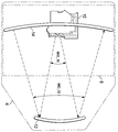
도 1은 실시예들에 따른 헤드 업 디스플레이(HUD) 장치의 자동차 응용예를 나타내는 사시도이다.
도 2a 및 도 2b는 각각 실시예에 따라 구성된 HUD 장치의 측면 및 후방 단면도이다.
도 2c는 실시예에 따른 도 2a 및 도 2b의 장치를 병합한 HUD 시스템의 측면도 및 기능도이다.
도 3a는 동작 시의 광 경로를 도시한, 실시예에 따른 HUD 장치의 측단면도이다.
도 3b는 동작 시의 광 경로 및 이미지 형성을 도시하는, 도 3a의 HUD 장치의 평면도이다.
도 4a 내지 도 4c는 종래의 평면 스크린 표면과 실시예에 따른 스크린의 표면을 비교하는, 반사광의 세기의 평면 개략도 및 관련 플롯(plot)들이다.
도 4d는 종래의 반사 표면에 대하여 광학적 이득 특성을 나타내는, 실시예의 HUD 장치의 스크린의 단면도이다.
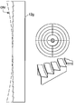
도 4e 내지 도 4g는 대안적인 각 실시예들에 따른 스크린의 측단면도이다.
도 5a는 실시예의 HUD 장치에서의 결합기(combiner)의 단면도이다.
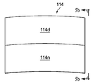
도 5b 및 도 5c는 각각 다른 실시예에 따른 다중 범위(multiple range) 결합기의 단면도 및 정면도이다.
도 6a 및 도 6b는 실시예에 따른, 스크린과 결합기의 상이한 각도 위치에서의 HUD 장치의 측면도이다.
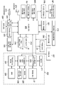
도 7은 실시예의 HUD 장치에서 제어 전자 장치의 아키텍처의 블록 형태의 전기 다이어그램이다.
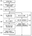
도 8은 실시예에 따른 제스처, 음성 입력 및 착신 통신에 응답하는, 실시예에 따른 HUD 장치의 동작을 나타내는 흐름도이다.
도 9a 및 도 9b는 도 8의 실시예에 따른 HUD 장치의 동작 예를 나타내는 흐름도이다.
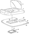
도 10은 실시예에 따른 HUD 장치의 주요 물리적 부품의 분해 사시도이다.
도 11은 실시예에 따른 HUD 장치의 하우징의 분해 사시도이다.
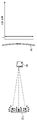
도 12a 및 도 12b는 각각 실시예에 따른 도 11의 하우징과 퍽의 결합(mating)을 도시한 평면도 및 단면도이다.
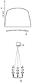
도 13a 내지 도 13f는 HUD 장치를 다양한 실시예들의 풋에 장착하는 평면도 및 정면도이다.1 is a perspective view showing an automotive application example of a head-up display (HUD) device according to embodiments.
Figures 2a and 2b are side and rear cross-sectional views, respectively, of a HUD device constructed according to an embodiment.
2C is a side view and function diagram of the HUD system incorporating the apparatus of FIGS. 2A and 2B according to an embodiment.
3A is a side cross-sectional view of the HUD apparatus according to the embodiment showing the optical path in operation.
Figure 3B is a top view of the HUD device of Figure 3A, showing the light path and image formation during operation.
Figures 4A-4C are plane schematic and related plots of the intensity of the reflected light, comparing the surface of a conventional flat screen surface with the screen according to an embodiment.
4D is a cross-sectional view of a screen of a HUD device of an embodiment showing optical gain characteristics for a conventional reflective surface.
4E-4G are side cross-sectional views of a screen according to alternative embodiments.
5A is a cross-sectional view of a combiner in the HUD device of the embodiment.
Figures 5B and 5C are cross-sectional and front views, respectively, of a multiple range coupler according to another embodiment.
6A and 6B are side views of the HUD device at different angular positions of the screen and combiner, according to an embodiment.
7 is an electrical diagram of a block form of the architecture of the control electronics in the HUD device of the embodiment.
Figure 8 is a flow diagram illustrating the operation of the HUD device in response to a gesture, voice input, and incoming communication according to an embodiment, in accordance with an embodiment.
FIGS. 9A and 9B are flowcharts showing an operation example of the HUD device according to the embodiment of FIG.
10 is an exploded perspective view of major physical components of the HUD device according to the embodiment.
11 is an exploded perspective view of the housing of the HUD apparatus according to the embodiment.
12A and 12B are a plan view and a cross-sectional view, respectively, illustrating the mating of the housing and puck of FIG. 11 according to an embodiment.
13A-13F are a top view and a front view, respectively, of mounting the HUD device to the foot of various embodiments.
본 명세서에서 설명되는 하나 이상의 실시 형태는, 자동차의 운전자에 의해 사용되는 헤드 업 디스플레이(HUD) 장치 및 시스템으로 구현되는데, 이러한 구현이 이 상황에서 특별히 유리하기 때문이라고 생각되기 때문이다. 그러나, 본 발명의 개념은 또한, 다른 응용예들, 예를 들어, 항공 및 해양 응용예뿐만 아니라 비디오 게임, 광고 디스플레이, 놀이 공원 디스플레이, 시뮬레이션 시스템, 및 투명 디스플레이가 유용할 수 있는 다른 응용예들을 포함하는(여기에 한정되지는 않음) 다른 응용예들에 유리하게 적용될 수 있다고 생각된다. 따라서, 이하의 설명은 단지 예로서 제공되는 것이며, 청구된 본 발명의 진정한 범위를 제한하려는 의도가 아님을 이해해야 한다.One or more of the embodiments described herein is implemented in a head-up display (HUD) device and system for use by a driver of a motor vehicle, since such an implementation is believed to be particularly advantageous in this situation. However, the concepts of the present invention may also be applied to other applications, such as video games, advertising displays, amusement park displays, simulation systems, and other applications where transparent displays may be useful, as well as other applications, But is not limited to these applications. It is, therefore, to be understood that the following description is given by way of example only and is not intended to limit the true scope of the claimed invention.
본 설명 및 전술한 것으로부터 명백해지듯이, 본 명세서에 기재된 발명의 실시예들은 일반적으로 "헤드 업 디스플레이(head-up disply)" 또는 "HUD"라고도 알려진 시스루(see-through) 디스플레이 장치에 관한 것이다. 도 1은 자동차 상황에서 이들 실시예에 따른 장치들의 일반적인 응용을 도시한다. 도 1에 도시된 바와 같이, 본 상황에서의 HUD 장치(2)는 자동차 대시보드(DSH)의 상단에 안치되는데, 일반적으로 대시보드(DSH) 내에 마련된 속도계 및 다른 계기판 또는 조작 디스플레이(도시되지 않음) 위쪽 및 핸들(steering wheel, SWH) 위쪽의 운전자(DRV)의 시야 내에 HUD 장치(2)가 안치된다. HUD 장치(2)는 차량을 운전하는 동안, 앞유리(WSH)를 통한 도로의 시야를 막지 않으면서, 운전자(DRV)와 관련된 정보를 디스플레이하는 시스루 이미지를 제공한다.As is apparent from the present description and above, embodiments of the invention described herein relate generally to a see-through display device, also known as a " head-up display "or" HUD ". Figure 1 shows a general application of devices according to these embodiments in an automotive situation. As shown in Fig. 1, the
다음 설명으로부터 분명한 것처럼, 본 실시예에 따른 HUD 장치(2)는 휴대가능하고, 다양한 차량의 대시보드(DSH) 위에 용이하게 배치되며, 운전자(DRV)가 공용 주차장에 차를 주차하고 있을 때와 같이 보안 목적으로 또는 다른 차량에서 사용하기 위해 용이하게 탈착 가능하도록 구성된다. 이와 같이, 이러한 실시예들에서 HUD 장치(2)는 운전자의 시야를 크게 방해하지 않으면서 대시보드(DSH) 상단에 안치될 수 있도록 컴팩트한 크기로 구성된다.As will be apparent from the following description, the
도 2a의 단면도는 일부 실시예들에 따른 HUD 장치(2)의 다양한 부품을 개략적으로 도시한다. 이 도면에 도시된 바와 같이, 하우징(4)은 예를 들어 하나 이상의 인쇄 회로 기판 상에 장착될 수 있는 제어 전자 장치(6)를 포함하며, 제어 전자 장치(6)는 후술하는 바와 같이, HUD 장치(2)의 동작과 관련된 데이터 및 이미지 처리를 수행한다. 몇몇 실시예에 따른 제어 전자 장치(6)의 아키텍처 및 기능을 아래에서 상세히 설명한다. The cross-sectional view of FIG. 2A schematically illustrates various components of the
하우징(4)은 또한 본 설명의 목적으로 프로젝션 시스템이라고도 일컫는 프로젝터 엔진(10)을 포함하는데, 이는 이러한 실시예들에 따라 HUD 장치(2)에 사용하기에 적합한 이미지를 투사하는데 필요한 광학기기, 광 변조, 광원 장치를 포함한다. 프로젝터 엔진(10)에 포함되는 광학기기는 적절한 렌즈, 거울, 광 균질화 장치, 편광 장치, 빛을 결합하는 이색성 필터와 같은 필터, 최신 프로젝터의 구성에 포함되는 당해 분야에 알려진 이러한 다른 광학 장치들 중 전부 또는 일부를 포함한다고 생각된다. 프로젝터 엔진(10)에 포함되는 광 변조 장치는 텍사스 인스트루먼트사의 DLP ™ 장치와 같은 디지털 마이크로거울 어레이 장치(digital micromirror array devices, DMD), LCOS(light crystal on silicon) 광 변조기, LCD 프로젝터 또는 다른 유형의 공간 광 변조기에서 사용되는 것과 같은 투과형 LCD 디스플레이와 같이 당해 분야에 공지된 것들을 포함하는 많은 유형들 중 임의의 하나일 수 있다; 일부 실시예들에서 사용되기에 적당한 다른 유형의 광 변조 장치는, 레이저 빔 스캐닝(laser beam scanning, LBS) 프로젝터 및 임의의 다른 형태의 이미지 프로젝션을 포함하는데, LBS 프로젝터에서는 레이저 광원이 전자적으로 또는 이와 다르게 변조되고, 이미지를 스캔하기 위하여 레이저 빔이 하나 이상의 이동 거울에 의해 스캐닝된다. 프로젝터 엔진(10)에 포함되는 광원은 하나 이상의 LED, 하나 이상의 레이저, 또는 다른 광원들일 수 있다. 예를 들어, 적색, 녹색 및 청색 LED 또는 레이저는 "풀 컬러(full color)" 디스플레이라고 알려진 것을 지원하기 위해 DMD 및 LCOS 변조기와 함께 흔히 사용되지만, 물론 다른 컬러의 빛도 추가적으로 또는 대안적으로 사용될 수 있다. 이러한 기술 중 어느 하나에서, 프로젝터 엔진(10)은 당해 분야에 공지된, 이러한 소자들을 제어하기 위한 적절한 전자 장치를 포함한다고 생각된다. The
프로젝터 엔진(10)은 이러한 실시예에서 하우징(4)의 후방 에지 근처에 장착된 스크린 인클로저(13) 내의 커브드 스크린(12)으로 이미지를 후방으로(즉, 운전자(DRV) 쪽으로) 투사한다. 아래에 상세히 설명되는 바와 같이, 스크린(12)은 반사 표면, 예를 들면 프로젝터 엔진(10)에 의해 투사된 빛이 스크린(12) 상에 "실제(real)" 이미지를 형성하도록 프로젝터 엔진(10)에 대해 위치된, 고이득(high-gain) 커브드 반사 표면이다. 스크린(12)의 구성은 아래에 더 상세히 설명할 것이다.The
이러한 실시예들에 따르면, 스크린(12)은 이러한 실제 이미지를 전방으로(즉, 앞유리 쪽으로) 결합기에 반사시킨다. 이러한 실시예들에 따른 결합기(14)는 두 방향으로부터의 빛, 즉, 앞유리(WSH)를 통하여 투과되는 빛과 스크린(12)으로부터 반사되는 빛을 결합하여, 도 1의 구성에서 운전자(DRV)가 볼 수 있는 결합된 "가상(virtual)" 이미지를 형성하는 반투명 커브드 소자이다. 차량 앞의 도로 상태 및 다른 시각적 정보가(즉, 앞유리(WH)를 통하여 들어오는 빛) 결합기(14)를 통하여 운전자(DRV)에게 보일 수 있지만, 프로젝터 엔진(10)에 의해 투사되고 스크린(12)에 의해 반사되는 이미지가 또한 운전자(DRV)에게 보일 수 있을 것이라는 점에서, 결합기(14)는 반투명이다. 결합기(14)의 구조는 아래에서 더 상세히 설명될 것이다.According to these embodiments, the
도 2b는 후방으로부터 즉 도 1의 운전자(DRV)의 관점으로부터의 HUD 장치(2)를 도시한다. 도 2b로부터 명백한 바와 같이, 운전자(DRV)는 스크린 인클로저(13)의 배면을 보고 있고, 스크린 인클로저(13) 내에 스크린(12)(도 2a)이 프로젝터 엔진(10)(도 2b에 가상선으로 도시함)에 대향하도록 배치되어 있다. 아래 상세히 설명하는 바와 같이, 스크린(12) 및 결합기(14)의 구성 및 배치 때문에, 프로젝터 엔진(10)에 의해 투사되는 빛에 의해 제공되는 이미지가 스크린(12)에서 이미지(IMG_12)를 형성한다. 도 2b에 도시된 바와 같이, 이 이미지(IMG_12)는 스크린(12)으로부터 반사되어 결합기(14) 상에서 이미지(IMG_14)로서 나타날 것이다. 따라서, 이미지(IMG_14)는 실행되고 있는 특정 기능에 적합하게 하우징(4) 내의 제어 전자 장치(6)에 의해 생성되는 그래픽 및 다른 시각 정보를 운전자(DRV)가 알아볼 수 있는 방식으로, 보여준다. 스크린 인클로저(13)는 도 2b의 도면에서 명백한 바와 같이, 프로젝터 엔진(10)에 의해 방사되는 빛이 직접 운전자(DRV)에게 도달하는 것을 차단하는 역할을 한다. 그리고 전술한 바와 같이 그리고 아래에서 좀 더 상세히 설명하는 바와 같이, 이러한 실시예들에 따르면 결합기(14)는 반투명이기 때문에, 이미지(IMG_14)가 도로의 시야 위에 효과적으로 오버레이(overlay)된 상태로 운전자(DRV)가 결합기(14)를 통하여 앞의 도로를 볼 수 있다.Fig. 2b shows the
도 2a 및 도 2b는 또한, 다양한 실시예들에서 구현될 수 있는 HUD 장치(2)의 다양한 보조 부품을 도시한다. 이러한 실시예에서 후방 대향 카메라(18R)가 스크린 인클로저(13)의 운전자 측 상에 장착되고, 이에 따라 운전자(DRV)를 향해 있다. 아래에서 더 상세히 설명되는 바와 같이, 후방 대향 카메라(18R)에 의해 취득된 이미지 데이터는 제어 전자 장치(6)로 전달되고, 제어 전자 장치(6)는 이 데이터를 처리하여 운전자(DRV)에 의해 취해지는 제스처를 식별하고, 식별된 이 제스처에 응답하여 다양한 제어 기능을 수행한다. 야간 조건에서 이 기능을 가능하게 하기 위해, 후방 대향 카메라(18R)는 적외선에 민감하고, 적외선 광원(19)(예를 들어, 적외선을 방사하는 LED)이 스크린 인클로저(13)의 운전자 측 표면 상에 장착되고, 또한 운전자(DRV)를 마주보고 있다. 이러한 실시예들에 따르면, 카메라(18R)에 의해 캡처되는 이미지에서 핸들(SWH)(도 1)의 음영 효과(shadowing effect)를 감소시키기 위해서는 적외선 광원(19)은 바람직하게는 후방 대향 카메라(18R) 위쪽에 장착된다는 것이 발견되었다. 다른 제스처-검출 기술이 후방 대향 카메라(18R) 대신에 또는 추가하여 대안적으로 구현될 수 있고, 이 예들은 깊이 센서, 광도 스테레오 센서(photometric stereo sensor), 및 듀얼 카메라 배치를 포함한다. 2A and 2B also show various auxiliary components of the
일부 실시예들에서, 직접 렌즈 빛 차단부(direct lens light block)(17)가 스크린 인클로저(13)의 상단 에지에 장착된다. 직접 렌즈 빛 차단부(17)는 프로젝터 엔진(10)에 의해 방사되는 빛이 특히 키가 큰 운전자의 경우, 운전자(DRV)의 눈에 직접 도달하는 것을 차단하는 불투명 구조이다. 예를 들어, 직접 렌즈 빛 차단부(17)은 다양한 설치에서 이러한 차광 기능을 달성하기 위해 운전자(DRV)에 의해 스크린 인클로저(13)의 상단 에지에 대하여 위 또는 아래로 조정 가능하게 슬라이딩될 수 있는 불투명 플라스틱 판으로서 구성될 수 있다.In some embodiments, a direct lens
전방 대향 카메라(18F)가 일부 실시예들에서 예를 들어, 결합기(14)의 상단 에지에 앞유리(WSH) 방향으로 향하여 장착되어 제공될 수 있다. 이러한 실시예들에서 전방 대향 카메라(18F)는 도로 차선 내 또는 차선 사이의 차량의 위치, 도로 상태, 또는 앞유리(WSH)를 통해 볼 수 있는 다른 환경적 파라미터에 관한 이미지 데이터를 제어 전자 장치(6)로 전달하고, 제어 전자 장치(6)는 결과적으로 이 정보에 응답하여 결합기(14)에 디스플레이하기 위한 정보를 생성한다. 도 2a는 또한 하우징(4) 상에 장착된 주변광 센서(21)를 도시하는데, 일부 실시예들에서 주변광 센서(21)는 주변광의 레벨을 제어 전자 장치(6)에 전달할 것이다; 원하면, 이러한 주변광 센서(21)를 하나보다 더 많이 HUD 장치(2)에 구현할 수 있다. 만일 주변광 센서(21)가 구현되면, 제어 전자 장치(6)는 프로젝터 엔진(10)에 의해 투사되는 빛의 밝기 및 다른 속성들을 조정하여, 일반적으로 주변이 밝은 상태에서 디스플레이되는 이미지의 밝기를 증가시키고, 야간에는 밝기를 감소시킨다. A forward facing
도 2a는 힌지(16C)에 의하여 하우징(4)에 물리적으로 결합된 결합기(14) 및 힌지(16S)에 의하여 하우징(4)에 물리적으로 결합된 스크린(12)을 도시한다. 힌지(16C)는 결합기(14)의 각도가 축에 대하여 회전 가능하게 조정되는 것을 가능하게 하고 힌지(16S)는 스크린(12)의 각도가 축에 대하여 회전 가능하게 조정되는 것을 가능하게 한다(이러한 축 각각은 도 2a에서 지면 안팎으로 들어가고 나온다). 이러한 조정가능성은 다양한 대시보드(DSH)의 기하학적 구조에 대하여(즉, 대시보드(DSH)의 최상면의 편평도에 관계 없이) 운전자(DRV)에게 디스플레이되는 이미지의 양호한 가시성을 보장하고, 이미지의 왜곡을 최소화하는데, 이하 더 상세하게 설명될 것이다.Figure 2a shows a
도 2c는 특정 실시예들에 따라, HUD 장치(2)를 자동차 환경에서의 다양한 기능과 함께 통신 시스템으로 구현한 것을 도시한 것이다. 이 예에서, HUD 장치(2)는 제어 전자 장치(6)의 일부로서 또는 이와 연계하여, 근처 장치들(즉, 차량 내)과의 로컬 통신을 위한 블루투스 또는 다른 NFC(near-field communications) 유형과 같은 종래 기술에 따라 무선 송신 및 수신을 수행할 수 있는 무선 통신 기능을 포함한다; 셀룰러, 위성, FM 및 다른 무선 통신과 같은 장거리(longer-range) 통신 기능이 부가적으로 또는 대안적으로 구현될 수 있다. 이 예에서, 시스템은 스마트폰(SPH)를 포함하는데, 스마트폰(SPH)은 일반적으로 운전자(DRV)에게 개인적인 것이며, HUD 장치(2)와 통신하기 위한 적절한 소프트웨어를 포함한다. 이러한 스마트폰(SPH)과의 통신에 의해, HUD 장치(2)는 교통, 날씨 정보, 텍스트 메시지, 이메일 등에 관한 온라인으로 액세스 가능한 정보를 디스플레이할 수 있을 것이다. 도 2c에 도시된 실시예의 시스템은 또한 하나 이상의 후방 카메라(rear camera, RCM)를 포함하는데, 후방 카메라(RCM)는 자동차 안, 예를 들어 차량의 외부 후방 상에 또는 운전석 뒤 또는 천정과 같이 차량 내부에 배치될 수 있다; HUD 장치(2)와 후방 카메라(RCM) 간의 통신은 HUD 장치(2)로 하여금, 운전자(DRV)가 물리적으로 뒤돌아보거나 눈을 도로에서 떼는 일이 없이 경우에 따라 차량 뒤쪽으로부터의 시야 또는 운전자(DRV) 뒤쪽의 내부의 시야를 보여주는 이미지를 결합기(14) 상에 디스플레이할 수 있도록 한다. 또한, 도 2c에 도시된 바와 같이, HUD 장치(2)의 USB 포트(21)가 HUD 장치(2)가 설치된 차량의 온보드 진단 포트(on-board diagnostic port, OBDP)와의 유선 통신을 위해 제공된다; 이 연결에 의해, 차량의 작동 파라미터 또는 상태에 관한 정보가 곧바로 또는 내비게이션 정보(다음 주유소까지의 거리)와 결합되어 결합기(14)에서 운전자(DRV)에게 디스플레이될 수 있다. 본 명세서를 참조하는 당업자는 이러한 기능들을 용이하게 구현할 수 있고, 과도한 실험 없이, 필요에 따라 도 2c에 도시된 것 이외의 다른 기능을 부가적으로 또는 대안적으로 구현할 수 있을 것이라고 생각된다.Figure 2C illustrates the implementation of the
도 3a 및 도 3b는 각각 본 발명의 일부 실시예들에 따른 기본 광 경로의 측면도와 평면도를 도시한다. 도 3a 및 도 3b 각각에 도시된 바와 같이 프로젝터 엔진(10)은 빛을 이미지 경로(IMG_10)를 따라 스크린(12) 쪽으로 투사하여, 스크린(12)에서 실제(인간이 볼 수 있는) 이미지를 형성한다. 이 이미지는 스크린(12)에 의해 반사되어 이미지 경로(IMG_12)를 따라 결합기(14)에 다다르고, 이어서 결합기(14)에 의해 부분 반사되어, 중심 가시선(center line-of-sight)(CLOS)을 따라 운전자(DRV)에게 보여질 수 있다. 앞에서 언급한 바와 같이, 결합기(14)는 앞유리(WSH)를 통해 수신되는 바와 같은 외부광에 반투명하도록 구성되어 있다; 이 반투명성은 또한 결합기가 스크린(12)에 의해 반사되는 빛에 준 반사적(semi-reflective)이라는 것을 내포한다. 이러한 특성들은 결합기(14)의 표면상의 코팅에 의해 달성될 수 있다. 예를 들어, 결합기(14)의 표면은 30% 반사 코팅을 가질 수 있는데, 이 경우 스크린(12)으로부터 반사되는 빛의 30%가 운전자(DRV) 쪽으로 반사되는 반면, 앞유리(WSH)를 통해 수신되는 외부광의 약 70%는 결합기(14)를 투과하여 운전자(DRV)에게 보여질 것이다. 실시예들에 따른 결합기(14)의 특정한 구성은 아래 더 상세히 설명할 것이다.Figs. 3A and 3B respectively show a side view and a plan view of a basic optical path according to some embodiments of the present invention. 3A and 3B, the
프로젝터 엔진(10)에 의해 스크린(12) 상에 투사되는 이미지는 "실제" 이미지이기 때문에, 스크린(12)에 촛점이 맞게 그 이미지를 투사하도록 프로젝터 엔진(10)을 구성하고 배치하는 것이 유용하다. 이 예에서, 스크린(12)은 프로젝터 엔진(10)의 렌즈의 초점면에 배치된다. 프로젝터 엔진(10)의 렌즈가 약 100mm의 초점 거리를 가지는 일 예에서, 스크린(12)은 프로젝터 엔진(10)으로부터 약 100mm의 거리에 배치된다. DMD 또는 LCOS 광 변조기형 프로젝터로서 구성된 프로젝터 엔진(10)의 경우, 제조시에 초점 조정이 요구될 수 있고, 그 후, 시스템 사용 시에는 고정된 채로 남는다. 그러나, 레이저 조명을 사용하는 프로젝터(10)의 경우, 초점 심도가 충분하여, 추가적인 포커싱이 필요하지 않을 수 있다. 또한, 레이저는 주어진 중심 주파수에서 훨씬 더 좁은 대역폭/선폭을 가지고 있기 때문에, 레이저의 사용은 대역 통과 필터와 같은 스크린(12)에서의 그러한 광학 소자로 더 나은 성능을 제공할 수 있다는 것은 당업자에 의해 이해될 것이다.Since the image projected on the
일부 실시예들에 따르면, 스크린(12)은 프로젝터 엔진(10)으로부터 빛을 수신하는 실질적으로 구형의 커브드 내부 표면을 갖도록 구성된다. 스크린(12)의 만곡도(degree of curvature)는 그 표면으로부터 결합기(14)로 반사되고, 그리고 결합기(14)로부터 반사되는 광선이 운전자(DRV)의 눈 동공에 초점이 맞춰지도록 선택된다. 운전자(DRV)의 눈 동공이 명목상 결합기(14)로부터 약 30 인치 되는 곳에 있는 것으로 예상되는, 자동차 환경에서의 대시보드 HUD 장치(2)의 일 예에서, 대략 440mm 정도의 스크린(12)의 내부 표면의 곡률 반경이 좋은 결과를 제공한다. 또한 당해 분야에 공지된 바와 같이, 구형의 표면은 구의 표면의 일부에 근사화된 오목면이다. 본 설명의 목적을 위해 "실질적으로 구형(substantially spherical)"이라는 용어는 완벽히 구형은 아니지만, 이러한 실시예들의 상황에서 완벽히 구형인 표면과 유사하게 행동하도록 구형에 충분히 가까운 표면을 일컫는다. 도 2b의 운전자의 시야를 참조하면, 만일 프로젝터 엔진(10)으로부터의 투사된 이미지가 투사 렌즈 오프셋 없는 평면 스크린을 위해 설계된다면, 이 이미지는 스크린(12)에서 스크린(12)의 경사 때문에 약간 키스톤되고(keystoned)(하단에서보다 상단에서 더 폭이 넓음), 스크린(12)의 만곡 때문에 약간 배럴 왜곡된(barrel distorted)(중심에서보다 스크린의 바깥쪽에서 더 작음) 것으로 나타날 것이다. 겉보기 배럴 왜곡은, 결합기(14)로 반사되어 결합기(14)에서 나타날 때, 커브드 스크린(12)의 바깥쪽이 스크린(12)의 중심보다 결합기(14)로부터 더 멀리 떨어져 있기 때문에 결합기(14)의 만곡의 광학 효과에 의해 더 증가될 것이다. 그러나, 일부 실시예들에서 스크린(12)은 "실질적으로 구형"인 표면을 가지도록 구성되는데, 이는 구체적으로 스크린(12)의 내부 표면의 경사 및 만곡으로부터 초래되는 키스톤 왜곡 또는 배럴 왜곡 또는 양쪽 모두를 보정하는데 도움이 되도록 표면을 약간 비구면으로 함으로써, 표면이 본 발명의 실시예들의 목적을 위하여 완벽히 구형인 것과 유사하게 행동하지만, 완벽히 구형은 아닌 것을 의미한다.According to some embodiments, the
대안적으로 또는 추가적으로, 이러한 왜곡들은 프로젝터 엔진(10) 내의 프로젝터 렌즈의 설계에 의해, 또는 결합기(14)를 (앞에서 정의된 "실질적으로 구형"을 유지하면서) 또한 약간 비구면으로 함으로써, 또는 운전자(DRV)에게 보일 때 결합기(14)에서 보정되어 보이도록 투사되는 이미지를 사전 왜곡하는 디지털 처리를 함으로써, 또는 이 모든 기술을 결합함으로써, 광학적으로 보정될 수 있다.Alternatively or additionally, such distortions may be caused by the design of the projector lens in the
이러한 실시예들에 따르면, 스크린(12)은 광학적 의미에서 높은 스크린 "이득"을 가지도록 구성된다. 당해 분야에 공지된 바와 같이, 스크린 이득은 스크린 표면에 법선인 방향으로 반사되는 빛의 피크 밝기의 측정치이다. 프로젝션 스크린의 분야에서 흔히 이해되는 바와 같이, 스크린 이득은 일반적으로 상대적인 측정치이며, 여기서 1.0의 이득이란, 빛이 흡수되지 않고 모든 빛이 재방사되어, 모든 시야각에서 완벽하게 균일하게, 스크린 상에 투사될 때와 동일한 밝기로 빛을 반사하는 스크린을 말한다. 이득은 전형적으로 스크린이 최고 밝기로 보이는 밴티지 지점(vantage point)에서 측정되는데, 이 밴티지 지점은 그 지점에서의 스크린의 접선에 대한 수직선 상에 있는, 스크린 바로 앞의 지점이다. 이에 따라, 이 지점에서의 이득의 측정은 "0도 시야각 축에서의 이득(Gain at Zero Degrees Viewing Axis)"으로서 알려져 있다. 1.0의 이득을 갖는 표면은 탄산 마그네슘(MgCO3)의 블록과 무광(matt) 화이트 스크린을 포함한다. 1.0보다 높은 이득을 갖는 스크린은 투사되는 것보다 더 밝은 빛을 반사할 것이다; 예를 들어, 1.5의 이득으로 등급이 매겨진 스크린은 1.0의 이득으로 등급이 매겨진 스크린보다 스크린에 법선인 방향으로 50% 더 많은 빛을 반사한다. 그러나, 1.0보다 큰 이득을 갖는 스크린은 모든 시야각에서 동일한 밝기로 빛을 반사하지는 않는다. 오히려 스크린을 어떤 각도에서 보기 위해 측면으로 이동한다면, 투사된 이미지의 밝기는 떨어질 것이다.According to these embodiments, the
도 4a 및 도 4b는 프로젝터 엔진(10)이 빛을 스크린 상으로 투사하고, 빛이 스크린으로부터 반사되어 커브드 결합기(14)로 향하는, HUD 장치(2)의 광학 배치의 상황에서의, 1(unity)(1.0) 이득의 상대적인 반사 밝기 및 고이득 평면 스크린을 각각 도시한다. 도 4a 및 도 4b의 도면은 도 3b에 도시된 것과 동일한 배향인 "평면도"이고, 각각의 스크린(112, 112')의 중심 및 두 개의 중심 이탈 지점들로 투사되는 균일 백색 이미지의 빛의 광 패턴을 보여주며, 각각의 스크린(112, 112')의 표면에서 반사되어 결합기(14)에 다다르는 광선의 프로파일을 도시한다. 도 4a에서의 스크린(112)은 종래의 1(unity) 이득 평면 스크린이고, 프로젝터 엔진(10) 바로 앞의 중심 위치(즉, 스크린(112)에 법선인 방향으로 빛을 수신하는 지점)로부터이건 아니면 프로젝터 엔진(10)으로부터 어떤 각도로 있는 중심 이탈 지점이건 간에, 프로젝터 엔진(10)으로부터 투사되는 빛은 스크린(112) 상의 각 지점으로부터 모든 방향으로 균일하게 반사한다. 스크린(112)의 1(unity) 이득 및 평평한 표면 때문에, 도 4a의 좌측에 그래프(plot)로 도시된 바와 같이, 결합기(14)의 표면을 따라 모든 지점에서 수신되는 반사광은 균일한 세기(즉, 1.0의 상대적 세기)를 갖는다. 그러나, 결합기(14)가 180도 확산(spread)의 일부분만을 커버하는 반면, 반사광은 스크린(112)의 표면으로부터 180도에 걸쳐 확산되는 점을 고려할 때, 스크린(112)으로부터 반사되는 빛의 많은 부분이 결합기(14)를 빗나갈 것이다. 프로젝터 엔진(10)에 의해 투사되는 균일한 백색 이미지의 경우, 결합기(14)를 보는 사람은 균일한 백색이되 희미한 이미지를 보게 될 것이다.Figures 4a and 4b illustrate how the
도 4b는 동일한 환경에서의 고이득(GX의 이득 > 1) 평면 스크린(112')의 반사 특성을 도시한다. 도면에 스크린(112')으로부터 반사되는 것으로 도시된 광선은 반사광의 진폭이 더 큰데(즉, 광선의 길이가 도 4a에서보다 더 김), 이는 스크린(112')이 스크린(112)보다 더 빛을 반사하지만, 반사광의 방향성은 도 4a의 스크린(112)으로부터의 것과 비교하여 중심 프로파일에 훨씬 더 한정되어 있음을 나타낸다. 반사광의 진폭은 가장 밝은 지점으로부터 멀어지면서 상대적으로 가파른 빛의 세기의 하락을 가진다. 스크린(112')의 중심 위치로부터의 반사광은 결합기(14)에서 집중 스팟(concentrated spot)으로서 수신될 것이다; 그러나 스크린(112')의 중심 이탈 위치로부터의 반사광은 결합기(14)를 빗겨나가도록 반사되는 경향이 있을 것이다. 이와 같이, 도 4b의 예에서 결합기(14)의 뷰어(viewer)는 중심에서 "핫 스팟(hot spot)"을 볼 것이며, 이 핫 스팟은 뷰어가 결합기(14)를 보는 각도에 맞춰(예를 들어, 도 4b에서 점선의 그래프에 의해 표시된 프로파일로) 이동하여, 임의의 시야각에서, 이미지는 한 부분에서 매우 밝은 스팟을 가지고, 이미지의 나머지 부분은 어둡게 될 것이다.4B shows the reflection characteristics of a high gain (gain of G x > 1) flat screen 112 'in the same environment. The light rays shown as being reflected from the screen 112 'in the figure have a larger amplitude of reflected light (i.e., the longer the light rays are longer than in FIG. 4A) But the directionality of the reflected light is much more limited to the central profile as compared to that from the
도 4c는 이러한 실시예들에 따른 HUD 장치(2)에서 사용되는, 실질적으로 구형인 고이득 스크린(12)에 의해 반사되는 빛의 성질을 나타낸다. 이 예에서는, 전술한 바와 같이 스크린(12)이 거울이라면, 프로젝터 엔진(10)이 초점이 되는 점에 가까이 있도록 스크린(12)의 곡률 반경은 프로젝터 엔진(10)과 스크린(12) 사이의 거리의 대략 두 배이다. 이 만곡은, 스크린(12)의 중심 이탈 위치로부터의 반사광선 번들이, 대부분 결합기(14)를 빗나가는 각도로 반사되기보다는, 스크린(12)의 중심 위치로부터 반사되는 빛에 대략 평행하게 반사되도록 한다. 도 4c의 좌측에 있는 빛 프로파일 그래프에 도시된 바와 같이, 이득 GX 및 스크린(2)의 만곡의 결과는 결합기(14)의 전 영역(full dimension)에 걸쳐 이득 GX에 거의 대응하는 세기로 꽤 균일하게 밝은 이미지이다. 실제로 이렇게 고이득의 실질적으로 구형인 커브드 표면으로서 스크린(12)을 구성하는 것은, 도 4b에서의 스크린(112')의 고이득의 장점과, 도 4a의 1(unity) 이득 스크린(112)의 근사적 균일성을 모두 제공한다. Figure 4c shows the nature of the light reflected by the substantially spherical
이러한 실시예들에 따르면, 실질적으로 구형인 스크린(12)은 저전력 프로젝터 엔진(10)으로부터도(즉, 이득 GX의 스크린(12)의 경우 1/GX 밝기로 빛을 투사함), 결합기(14)에서의 이미지의 밝기에 있어 양호한 균일성을 가지고 평평한 1(unity) 이득 스크린에 의해 제공되는 만큼 밝게 인식될 수 있는 이미지를 생성할 수 있다. 프로젝터 엔진(10)에 의해 출력되는 빛의 세기를 감소시키는 이러한 능력은 HUD 장치(2)에 의해 생성되는 열과 소비되는 전력을 감소시켜, 결과적으로 전체적인 시스템 비용을 낮춘다. 또한, 스크린(12)의 고이득은 특히 주변광을 포함하는 빛과 같이, 프로젝터 엔진(1)으로부터가 아닌 다른 방향으로부터의 빛이 결합기(14)로 반사되는 것을 거부하게 하는 것을 증가시킨다. In accordance with these embodiments, the substantially
이러한 실시예들에 따르면, 스크린(12)의 이득이 반드시, 얻을 수 있는 최고의 이득일 필요는 없다. 만일 스크린(12)이 높은 반사율의 거울이라면(순수한 거울은 무한 이득을 가질 것임), 결합기(14)에서의 이미지는 스크린(12) 상에 투사되는 이미지와 동일한 크기의 밝은 사각형으로서만 나타날 것이어서, 자동차 환경에서 운전자(DRV)가 용이하게 보기에는 너무 작다. 따라서, 스크린(12)은 표면에서 반사되는 빛을 다소 산란(diffusion)시켜, 반사된 이미지를 스크린(12) 그 자체보다 더 넓게 확산(spread)하는 것이 유용하다. According to these embodiments, the gain of the
이러한 실시예들에 따르면, 스크린(12)은 거울의 이득에 육박하게 매우 높은 이득을 가지도록 구성되지만, (즉, "거울"이 아니라, "스크린"으로서 기능할 수 있게 하기 위해) 충분한 산란 또는 이미지가 보일 수 있는 다른 광 산란 특성을 가지도록 구성된다. 예를 들어, 스크린(12)은 적어도 4.0의 이득, 바람직하게는 6.0 이상의 이득, 및 적어도 약 20.0 만큼 높은 이득을 가지도록 구성될 수 있다고 생각된다; 스크린(12)에 대한 이러한 이득은 0.7 내지 2.5 사이의 종래의 프로젝션 스크린 이득과 비교할 때 매우 높다. 이러한 매우 높은 이득에서 스크린(12)은 약간 산란성 거울로서 행동하고, 이는 양호한 이미지의 생성에 기여한다. 스크린(12)의 표면에서의 산란은 스크린(12)의 반사성 내부 표면에 대하여 다소 거친 물질을 선택하거나, 표면을 약간 거칠게 하거나, 그 표면에 코팅을 도포함으로써 실현될 수 있다. 또한 전술한 바와 같이 스크린(12)은 키스톤 및 배럴 왜곡을 보정하는데 도움이 되도록 실질적인 구형을 유지하면서 약간 비구면인 것이 바람직할 수 있다. 이러한 효과로 인하여 약간 상이한 빛 프로파일이 생기고, 반사광이 좀 더 많이 확산(spread)되고, 결합기(14)의 중심 영역에서 반사광의 세기는 다소 덜 균일하게 된다. 스크린(12)의 표면에서의 이러한 산란성으로 인하여 반사광은 스크린(12)의 표면에 뚜렷하게 집중되지 않게 되는데, 이는 본 발명에 따라 스크린(12)의 광학 특성을 향상시키기 위하여 발견되었다. According to these embodiments, the
이제 도 4d를 참조하여 본 실시예에 따른 스크린(12)의 구성을 좀 더 상세히 설명하겠다. 전술한 바와 같이, 스크린(12)의 기능은 프로젝터 엔진(10)에 의해 스크린에 투사된 빛을 산란시켜, 결합기(14)에서 "실제"(즉, 볼 수 있는) 이미지를 생성하는 것이다. 이러한 실시예에서, 스크린(12)의 모양, 특히 내측(즉, 오목한) 반사면의 모양은 전술한 바와 같이 실질적으로 구형이다. 이러한 실시예들에 따른 HUD 장치(2)에서, 내부 표면에 입사하는 프로젝터 엔진(10)으로부터의 빛이 스크린(12)에 의해 통과되어 운전자(DRV)에게 전송되지 않도록 스크린(12)은 바람직하게는 불투명이다. 이와 같이, 본 실시예에 따른 스크린(12)은 유리, 플라스틱, 또는 자체로 불투명하거나(즉, 빛 흡수제) 빛 흡수 물질로 코팅되어 있는(즉, 거울의 뒷면과 유사함) 구조적인 관점에서 적당한 다른 지지 물질로 구성된 지지 구조(30)를 포함하고, 전술한 바와 같이 높은 이득으로 입사광을 반사하기 위하여 매끄럽거나(smooth) 아니면 반사성의 내부(오목) 표면(32)을 가진다. 내부 표면(32)은 물질에 따라 지지 구조(30)의 표면으로서 간단하게 구성되거나, 지지 구조(30)에 도포되는 알루미늄 또는 스테인레스 스틸과 같은 물질로서 구성되거나, 지지 구조(30)의 표면에 도포되는 특수 스크린 플라스틱 막, 금속막이나 호일 또는 다른 유형의 반사 코팅으로서 구성될 수 있다. 어떤 경우에라도, 스크린(12)의 내부 표면(32)은, 물질 고유의 특성이든, 내부 표면(32)을 거칠게 하거나 코팅을 도포함으로써 얻어지는 특성이든 간에, 산란 특성을 가지고 있어야 한다.Referring now to Figure 4d, the construction of the
도 4d의 실시예에서 스크린(12)은, 광원이 상대적으로 좁은 대역 내에서 빛을 방사하는 LED 또는 레이저인, 프로젝터 엔진(10)을 이용하도록 구성된다. 이러한 실시예에 따르면, 이러한 좁은 대역은, 도 4d에 도시된 바와 같이 스크린(12)의 내부 표면(32)에 이색성 코팅(dichroic coating, 34)을 도포하고 이러한 이색성 코팅(34)을 LED 및 레이저 광원의 파장에 튜닝시킴으로써 HUD 장치(2)의 광학 성능 및 특성을 더 향상시키기 위해 활용될 수 있다. 일 실시예에 따르면, 이러한 이색성 코팅(34)은 프로젝터 엔진(10)에 의해 방사되는 빛의 3가지 색(적색, 녹색, 청색)에 집중된 특정한 파장 대역을 통과시키지만, 스크린(12)에 영향을 줄 수 있는 주변광의 많은 부분을 비롯하여 다른 파장의 빛을 (예를 들어, 흡수 또는 투과시킴으로써) 제외시키는 "삼중 대역 통과 필터(triple bandpass filter)"를 구성할 수 있다. 이렇게 해서, 결합기(14)로 반사되고 운전자(DRV)에게 보이는 이미지의 콘스라스트는 향상될 것이다.In the embodiment of Fig. 4d, the
예를 들어, 스크래치 내성과 같은 기계적 특성을 향상시키기 위하여, 다른 코팅이 스크린(12)의 내부 표면(32)에 도포될 수 있다.For example, other coatings may be applied to the
실질적으로 구형 모양인 스크린(12)은 높은 스크린 이득으로 인하여, 상당히 지향성이다. 이와 같이, 이러한 실시예들에서 스크린(12)은 도 3a에 도시된 바와 같이 프로젝터 엔진(10)으로부터의 투사된 빛의 방향에 대하여 위쪽으로 기울어져 있다. 최적의 밝기의 경우, 이러한 상향 경사의 각도는 투사된 빛과 결합기(14)의 중심 사이의 각도 θ보다 작은데, 예를 들어, 약 θ/2의 상향 경사이다. 일부 실시예들에서 스크린(12)의 위치 및 경사각(예: θ/2)은 고정되어 있을 수 있다; 다른 실시예들에서는 스크린(12)은 그 조준을 결합기(14) 쪽으로 조정하거나, 보관을 위해 스크린(12)을 닫기 위하여 기울어질 수 있다.The
일부 구현예에서 이러한 스크린(12)의 경사로 인하여 결합기(14)에서 볼 때, 반사되는 이미지는 약간 키스톤되거나 하단보다 상단에서 더 넓어질 것이다. 전술한 바와 같이, 이러한 키스톤 효과는, 예를 들어 프로젝터 엔진(10)의 렌즈로 또는 약간 비구면 내부 표면을 가지도록 스크린(12)을 구성함으로써 광학적으로, 또는 예를 들어, 키스톤을 보상하여 결합기(14)에서 왜곡되지 않은 이미지를 제공하도록 이미지 데이터를 사전-처리함으로써 디지털적으로, 감소될 수 있다. 원한다면, 이러한 키스톤을 보정하기 위한 사전-처리는 결합기(14)에서의 이미지의 외관상 크기가 운전자의 눈과 결합기(14) 사이의 거리에 따라 변한다는 것을 고려하여, 디지털 조정 및 사전 왜곡이 운전자의 눈 위치의 차이를 고려하도록, 후방 대향 카메라(rear facing camera, RCM)로부터의 정보에 일부 기초할 수 있다.In some embodiments, when viewed in
다른 실시예들에 따르면, 도 4e 내지 도 4g의 측단면도에 도시된 바와 같이(즉, 도 3a와 동일한 방향을 취함), 스크린(12)은 내부 오목면에 변화를 가지도록 구성될 수 있다. 도 4e를 먼저 참조하면, 스크린(12e)은 조각 세그먼트(piece-wise segments)로서 구성된 내부 표면을 가지도록 도시되어 있고, 각 세그먼트는 상향 경사를 가진 투사된 이미지를 결합기(14) 쪽으로 반사시킨다. 이러한 조각 경사의 목적은 전체 스크린(12)을 상향 경사지게 하는 것을 제거하거나 감소시키는 것인데, 이는 키스톤 이미지 왜곡 및 이미지의 촛점의 변화를 감소시키거나 제거한다. 결합기(14)에서의 이미지에서 조각 세그먼트 경계에서 보이는 아티팩트(artifact)를 감소시키기 위하여 이러한 조각 섹션을 극단적으로 작게 만들 수 있다고 생각되기 때문에, 도 4e 내지 도 4g에 도시된 이러한 조각 섹션의 상대 길이는 설명의 목적만을 위한 것이다. 도 4f의 스크린(12f)에 도시된 바와 같이, 조각 섹션의 내부 표면은 전체적인 구형 만곡과 결합될 수 있다. According to other embodiments, the
도 4g에 도시된 다른 실시예에 따르면, 스크린(12g)은 "프레넬 스크린(Fresnel Screen)"으로서 구성될 수 있는데, 프레넬 스크린에서는 스크린의 만곡이 프레넬 렌즈 및 거울의 분야에서 공지된 바와 같이, 구형 스크린의 원래 만곡을 조각별로 평탄화함으로써(도 4g에 점선으로 도시됨) 실현된다. 그러나, 프레넬 거울과 달리, 스크린(12g)의 내부 표면은 전술한 바와 같이 다소 산란되어, 빛이 투사될 때 "실제" 이미지가 나타날 것이다. 프레넬 스크린(12g)의 조각 세그먼트의 사이즈는 (현미경으로 봐야만 보일 만큼 작은) 매우 작은 사이즈를 포함하여 어떤 사이즈라도 될 수 있으므로, 반사된 이미지에서 뚜렷한 가시 효과를 감소시킬 수 있다.According to another embodiment shown in Fig. 4g, the
전술한 바와 같이, 결합기(14)는 앞유리(WSH)로부터의 빛을 스크린(12)으로부터의 내부 표면상에 반사되는 이미지와 결합하여, 운전자(DRV)가 인지할 수 있는 결합된 이미지를 형성하는 반투명 커브드 소자이다. 또한, 이러한 실시예들에서 결합기(14)는 스크린(12)에 투사되는 이미지를 확대하는데, 이는 스크린(12)을 수직으로 더 짧게 하여, 스크린(12)의 상단 위에서 운전자(DRV)에게 결합기(14)가 더 용이하게 보일 수 있게 한다. 또한, 아래 더 상세히 설명하는 바와 같이, 결합기(14)의 배치 및 모양은 인식된 이미지의 초점을 실제 위치보다 운전자(DRV)로부터 더 멀리 움직이는데 효과적이다. 결과적으로, 이러한 실시예들에서 결합기(14)는 이 이미지를 운전자(DRV)의 원거리 시야로 배치할 것이고, 이에 따라 운전자가 도로, 교통, 그리고 차량 전방의 멀리 외부에 보이는 다른 것들과 함께 HUD 장치(2)에 의해 제시되는 이미지에 집중하는 것을 더욱 용이하게 한다.As described above, the
도 5a의 단면에 도시된 일 실시예에 따르면, 결합기(14)는 주요 구조 소자로서, 폴리카보네이트(예를 들어, UV 안정화된 폴리카보네이트) 또는 다른 투명 플라스틱, 또는 바람직하게는 광학 품질인 유리 물질로 형성된 투명 광학 소자(40)를 포함한다. 광학 소자(40)는 전형적으로 수 밀리미터 정도의 두께를 가질 것으로 예상된다. 이 설명으로부터 명백한 바와 같이, 외부 광을 반사된 이미지와 결합시키는 기능을 수행하기 위해, 광학 소자(40)는 예를 들어, 도 3a의 배치에서 앞유리(WSH)를 통해서와 같이, 자신에게 수신된 입사광을 투과시키는 외부 표면(즉, 볼록면)과, 스크린(12)으로부터 자신에게로 반사된 입사광을 반사시키는 내부 표면(즉, 오목면)을 정의한다.According to one embodiment shown in the cross-section of Figure 5a, the
도 5a에 도시된 실시예에 따르면, 광학 소자(40)는 스크린(12) 상에 투사된 이미지를 운전자(DRV)가 보기 위해 필요한 반사 특성을 제공하기 위해 그 내부 표면상에 반사 코팅(42)을 갖는다. 증기 증착된 알루미늄 또는 다른 금속과 같은 거울 코팅을 포함하여, 다양한 물질이 코팅(42)에 적합하고, 이는 대부분의 파장을 상당히 똑같이 반사할 것이다. 코팅(42)은 바람직하게는 스크린(12)으로부터 보내진 (즉, 결합기(14)의 오목면을 향하는) 빛에 대해 전반사하지 않을 것이다; 예를 들어, 일 예에서 증기 증착된 알루미늄의 코팅(42)은 스크린(12)으로부터의 빛에 대해 약 30%의 반사율을 가지며 반대 방향으로부터 (즉, 도 3a의 배치에서의 앞유리(WSH)로부터) 오는 빛에 대해 약 70%의 투과율을 갖는다. 다른 구현에 따르면, 코팅(42)은 앞유리(WSH)를 통과하여 결합기(14)의 외부 표면에 부딪히는 외부 가시광선에 대체로 투명하면서, 프로젝터 엔진(10)에 의해 방사된 빛의 컬러를 반사시키는 삼중 대역 통과 필터를 구현하기 위해 스크린(12)과 관련하여 전술한 바와 같은 종래의 이색성 반사 코팅으로서 구현될 수 있다, 예를 들어, 만일 프로젝터 엔진(10)이 광원으로서 레이저를 포함한다면, 코팅(42)은 상대적으로 좁은 반사 파장 대역을 가지고 이에 따라 매우 넓은 통과 대역이 차량 전방으로부터의 외부광을 통과시키도록 선택된다. 이러한 구성은 후방으로부터 차량으로 들어오는 햇빛이 운전자(DRV)의 눈으로 다시 거의 반사되지 않도록 초래하고 이는 밝은 햇빛 조건에서 결합기(14)에서 보이는 이미지의 콘트라스트를 향상시킬 것이다. According to the embodiment shown in FIG. 5A, the
이러한 HUD 장치(2)의 배치에서, 스크린(12) 상의 실제 이미지가 확대되어, 가상 이미지로서 결합기(14)에 의해 운전자(DRV)의 방향으로 반사된다. 이와 같이, 결합기(14)의 초점 길이 및 배치는 그 가상 이미지의 확대와 겉보기(apparent) 이미지 초점 거리를 결정한다. 본 기술 분야에서 잘 알 수 있는 바와 같이, 오목 구면 거울(이 경우, 결합기(14))에 보이는 객체(이 경우에, 스크린(12)의 이미지)는 확대될 것이고, 겉보기 초점은 거울의 초점 길이, 거울로부터 객체의 거리, 거울로부터 관찰자의 거리의 함수로서 변화할 것이다. 이러한 거울에서 초점과 반사 오목면 사이에 위치한 객체의 반사된 이미지는 확대될 것이고, 객체가 물리적으로 있는 것보다 초점 및 위치 측면 모두에서 눈에 "가상으로(virtually)" 더 멀리 있는 것으로 보일 것이다. 일반적으로, 객체가 거울의 초점 길이에 근접할 때, 확대는 증가하고, 객체는 위치 및 초점 측면 모두에서 거울 뒤쪽으로 더 멀리 있는 것으로 보인다. 전술한 바와 같이, 결합기(14)에 있는 가상 이미지가 운전자(DRV)로부터 결합기(14)를 넘어선 거리에서(예를 들어, 광학적 의미에서 "무한"으로) 나타나서, 운전자가 눈을 도로에서 떼지 않고 디스플레이된 정보를 용이하게 볼 수 있어야 하는 것이 더 선호된다.In this arrangement of the
이제 이러한 본 발명의 실시예와 관련하여 설명되는 바와 같이, 스크린(12)으로부터 결합기(14)의 곡률 거리 및 결합기(14)의 곡률 반경은 이러한 개념에 따라 선택된다. 물리학의 문제로서, 반경 "R"의 실질적으로 구형인 반사 표면은 R/2의 초점을 가질 것이다. 이러한 설명의 목적을 위해, 결합기(14)의 반경은 광학 소자(40)의 내부 표면의 일반적인 곡률로서 정의될 것이다; 일반적으로 결합기(14)의 외측은 대략 광학 소자(40)의 두께만큼 내측의 곡률 반경과 상이한 곡률 반경을 가질 것이다. 광학 소자(40)와 같이 유사한 곡률 반경을 가진 내부 표면과 외부 표면을 포함하는 투명한 구면 소자를 통과하여 지나가는 빛은 최소한으로 왜곡될 것이고, 그 확대도 최소한 영향을 받을 것이라는 것이 관찰되었다. 결합기(14)에서 반사된 가상 이미지가 먼거리로 나타나는 거리는 스크린(12)과 결합기(14) 사이의 거리가 결합기(14)의 초점 거리에 근접함에 따라 증가하기 때문에, 결합기(14)로부터 스크린(12)까지의 거리는 결합기(14)의 초점 거리를 초과하지 않고 가능한 커야 한다. 역으로, 만일 이 거리가 결합기(14)의 초점 길이를 초과한다면, 이미지는 불안정하게 된다. 일 구현예에서 예를 들어, 광학 소자(40)의 내부 표면에 대하여 약 300mm인 곡률 반경이 선택되었다면, 결합기(14)에 대하여 약 150mm의 초점 길이를 초래한다. 이 구현에서는 후술하는 바와 같이 스크린(12)과 결합기(14)의 조정 가능성을 특히 고려하여 이러한 불안정성에 대한 가능성을 피하기 위한 45mm의 마진을 제공하기 위하여, 결합기(14)와 스크린(12) 사이에 약 115mm의 거리가 선택되었다. 이 배치에서 스크린(12)과 결합기(14) 사이의 거리가 결합기(14)의 곡률 반경의 1/2보다 작은 것은 결합기(14)가 실제 있는 것보다 운전자(DRV)의 전방에 더 먼 거리에 있는 것으로 보이는 결합기(14)의 내부 표면 상의 스크린(12)으로부터의 확대된 가상 반사 이미지와 함께, 결합기(14)로 인한 최소 왜곡 및 확대를 가지고 결합기(14)를 통하여 앞유리(WSH) 바깥의 시야를 운전자(DRV)에게 제공한다. 이러한 실시예들에서, 광학 소자(40) 및 따라서 결합기(14)는 바람직하게는 "실질적으로 구형인" 표면이 되도록 만곡되는데, 이는 본 실시예들의 상황 내에서 완벽히 구형은 아니지만, 완벽히 구형인 표면과 유사하게 행동하도록 구형인 것에 충분히 가깝다는 것을 의미한다. 이러한 실시예들에 따르면, 약간 비구면이지만, 여전히 실질적으로 구형인 결합기(14)의 내부 표면을 제공하는 것은 스크린(12)으로부터 결합기(14)로 반사될 때 이미지의 키스톤 및 배럴 왜곡을 보정하는데 도움이 된다.The curvature distance of the
도 5a에 도시된 실시예에서 결합기(14)는 또한, 광학 소자(40)에서의 양 방향으로의 빛 투과를 향상시키고 이중 이미지가 운전자(DRV)에게 또렷이 보이는 것을 감소시키기 위하여 외부 또는 볼록 표면상에 배치된 반사 방지 코팅(44)을 가진다. 반사 방지 코팅(44)은 당해 분야에 공지된 코팅을 위한 종래의 재료로 형성되고, 종래의 방식으로 광 소자(40)에 도포될 수 있다고 생각된다. The
도 5b 및 도 5c는 다른 실시예에 따라 "다중 범위(multiple range)" 결합기(114)를 도시한다. 다중 범위 결합기(114)는 이 구현에서 하부 부분(lower portion, 114n)과 상이한 곡률 반경 및 따라서 상이한 초점 길이를 가진 상부 부분(upper portion, 114f)을 구비하고 이들 둘 사이에 도시된 바와 같이 급격한 전이를 둠으로써, 하나보다 많은 초점 길이를 가지도록 구성된다. 대안적으로 결합기(114)는 예를 들어, 누진 초점 안경과 유사하게 초점 길이의 점진적 변화를 가지고, 상이한 초점 길이 부분 간에 매끄러운 전이를 가지도록 구성될 수 있다. 곡률 반경의 차이가 결합기 부분(114f, 114n)의 오목면 및 볼록면 모두에 대해 구현될 수 있거나, 대안적으로 오목면에만 (즉, 광학 소자의 두께를 변화시킴으로써 외부 표면상에 일정한 곡률 반경을 유지하면서) 구현될 수 있다. 도 5b 및 도 5c의 예에서 상부 부분(114f)은 하부 부분(114n)보다 더 짧은 곡률 반경 및 따라서 더 짧은 초점 길이를 가진다. 결과적으로, 부분(114f, 114n)은 본질적으로 스크린(12)으로부터 동일한 거리에 있기 때문에, 더 짧은 초점 길이를 가진 상부 부분(114f)에서 스크린(12)으로부터 반사된 이미지는 더 멀리 있는 것으로 나타날 것이고, 하부 부분(114n)보다 더 확대될 것이다. 이러한 대안적 구성의 변형이 또한 고려될 수 있는데 예를 들어, 추가적인 부분들을 제공함으로써 두 개보다 더 많은 확대가 구현될 수 있다; 더욱이 대안적으로 도 5b 및 도 5c의 상부 배치 및 하부 배치가 아니라, 상이한 확대 부분이 나란히 실현될 수 있다. Figures 5B and 5C illustrate a "multiple range"
다시 도 3a를 참조하여, 이제 본 실시예에 따른 HUD 장치(2)에서의 프로젝터 엔진(10), 스크린(12), 및 결합기(14)의 배치의 전체적인 기능을 설명하겠다. 전술한 바와 같이, 프로젝터 엔진(10)은 이미지 경로(IMG_10)를 따라 스크린(12) 쪽으로 빛을 투사하여, 예를 들어 운전자(DRV)의 요청에 따라 또는 이와 달리 차량의 작동에 관련되어 제어 전자 장치(6)에 의해 생성된 정보에 대응하는 실제(인간이 볼 수 있는) 이미지를 스크린(12)에 형성한다. 전술한 바와 같이, 스크린(12)은 (예를 들어, 각도 θ/2 만큼) 위쪽으로 기울어져 있고 내부 반사면을 가지고 있기 때문에, 이미지는 결과적으로 이미지 경로(IMG_12)를 따라 결합기(14)로 반사된다. 전술한 바와 같이 반투명인 결합기(14)는 그 내부 표면으로부터 "가상" 이미지를 반사시키고 또한, 앞유리(WSH)를 통해 수신되는 외부 광을 투과시켜서, 이 결합은 중심 가시선(CLOS)을 따라 운전자(DRV)에게 보일 수 있는 이미지가 생기게 한다.Referring again to FIG. 3A, the overall function of the arrangement of the
전술한 바와 같이, 스크린(12)은 프로젝터 엔진(10)으로부터의 거리의 약 두배인 곡률 반경을 가진 실질적으로 구형인 내부 표면을 가지고 있다. 결과적으로 프로젝터 엔진(10)은 대략 커브드 반사 내부 표면의 초점에서 스크린(12)으로부터 떨어져 있으므로, 실제 이미지가 스크린(12)에 나타난다. 예를 들어, 본 실시예에 따른 HUD 장치(2)의 한가지 구현은 프로젝터 엔진(10)으로부터 약 100mm의 거리에 위치하고, 약 200mm의 곡률 반경을 가진 고이득 내부 반사 표면을 가진 스크린(12)을 포함한다. 스크린(12)의 이러한 내부 표면은 거칠게 하기 또는 코팅에 의해 실제 이미지를 약간 산란시켜서, 스크린(12)에서의 이러한 실제 이미지는 보이기는 하나 선명하게 초점이 맞춰지진 않는다. 스크린(12)의 이러한 내부 표면은 이 내부 표면이 반사하는 빛이 뛰어난 밝기를 가지고, 스크린(12)의 상향 경사로 인해 결합기(14)의 넓은 부분에 걸쳐 비교적 균일하게 조사되도록, 고이득을 가진다. 도 4e 내지 도 4g에서 설명된 바와 같이, 투사된 빛 성분에 대하여 대역 통과 필터를 제공하기 위한 내부 표면에서의 이색성 코팅(34) 및 내부 표면의 조각별 모양(piece-wise shaping)과 같이 스크린(12)의 추가적인 특징들은 이러한 실시예에 따른 HUD 장치(2)의 배치에서 스크린(12)의 광학 특성을 더 향상시키기 위하여 선택적으로 제공될 수 있다.As described above, the
결합기(14)는 프로젝터 엔진(10) 위에 위치한 반투명 결합기(14)의 내부 표면의 곡률 반경의 1/2보다 작은 거리에서 도 3a의 경로(IMG_12)를 따라 위치한다. 결합기(14)의 이러한 위치 및 모양은 스크린(12)에 의해 반사된 이미지가 결합기(14)에서 나타날 때 이 이미지를 확대시키고, 그 확대된 이미지를 결합기(14) 그 자체의 물리적 위치보다 더 운전자(DRV) 앞쪽에 있는 겉보기 초점에서 반사시킨다. 사용자에게 확대되고 더 멀리 있는 것으로 보이는 스크린 상의 이미지는 당업자에 의해 "가상 이미지"인 것으로 고려되고, 운전자(DRV)의 머리의 이동은 또한 결합기(14)에서의 이미지를 "이동시켜" 넓은 각도에 걸쳐 디스플레이된 이미지의 양호한 가시성을 제공한다. 스크린(12)에서의 실제 이미지에 대한 결합기(14) 상의 가상 이미지의 확대는 스크린(12)이 수직 차원에서 물리적으로 더 짧은 것을 가능하게 하고, 이는 운전자(DRV)가 스크린(12) 너머로 보아 결합기(14) 상의 이미지를 보는 것을 용이하게 한다. 결합기(14)의 반투명 성질 때문에, 이러한 확대되고 먼거리 초점이 있는 이미지는 운전자(DRV)의 관점에서 결합기(14)의 전측 외부 표면으로부터 결합기(14)를 투과하는 외부 뷰와 결합된다. 따라서, 이러한 실시예에 따른 HUD 장치(2)의 이러한 배치의 결과는 운전자(DRV)가 관련 정보를 보기 위하여 앞의 도로로부터 그의 초점을 상당히 변경시킬 필요없이, 제어 전자 장치(6)에 의해 생성되는 관련 정보를 운전자(DRV)에게 편리하게 제공한다. 이러한 유리한 결과는, 본 실시예에 따르면, 광범위한 자동차, 트럭 및 다른 차량에서 배치 가능하고, 용이하게 이동 및 탈착 가능한, 편리한 휴대용 대시보드-상단 모듈로서 패키징될 수 있는 HUD 장치(2)에 의해 제공된다.The
본 발명과 관련하여, HUD 장치(2)의 후방 근처에서(즉, 운전자(DRV)로부터 가장 멀리) 결합기(14) 아래 및 제어 전자 장치(6) 위에 프로젝터 엔진(10)을 배치하는 것은 여러 장점을 제공한다. 하우징(4)의 경계 내에서 프로젝터 엔진(10)을 스크린(12)으로부터 가능한 멀리 위치시킴으로써, 스크린(12)의 필요한 경사각이 감소될 수 있고, 이는 결국 키스톤 왜곡을 감소시킨다. 또한, 스크린(12)의 곡률 반경은 프로젝터 엔진(10)이 스크린(12)의 초점 근처에 있도록 하기 위하여 최적으로는 프로젝터 엔진(10)과 스크린(12) 사이의 거리의 약 두 배이기 때문에, 이러한 거리를 최대화함으로써 스크린(12)의 곡률 반경이 가능한 크게 되어, 스크린(12)으로부터 결합기(14)로 반사되는 이미지의 왜곡을 최소화시킨다(프로젝터 엔진(10)을 더 가까이 배치하는 것은 스크린(12)이 더 짧은 곡률 반경을 가지도록 요구할 것이고, 이는 이미지의 왜곡을 증가시킨다). 프로젝터 엔진(10)을 제어 전자 장치(6) 위에 배치하는 것은 제어 전자 장치(6)가 배치된 인쇄 회로 기판 또는 기판들이 프로젝터 엔진(10)과 스크린(12) 사이의 빛 경로를 방해하지 않는 것을 보장하여, 제어 전자 장치(6) 내의 부품들에 대한 폼 팩터 제한을 완화하고, 또한 더 컴팩트화된 제품 디자인을 제공한다.In connection with the present invention, placing the
또한, 도 3a는 프로젝터 엔진(10) 위쪽에서 이 프로젝터 엔진(10)을 넘어, 운전자(DRV) 방향으로 후방으로 연장하는 "빛 후드(light hood)"(4H)를 가지는 하우징(4)을 도시한다. 빛 후드(4H)는 운전자(DRV) 눈에 불편하도록 밝게 보이는, 프로젝터 엔진(10)의 렌즈를 스크린(12) 상단 위쪽에서 운전자(DRV)가 직접 보는 것을 막는데 도움이 된다. 물론, 빛 후드(4H)는 스크린(12)에 투사되는 이미지를 막지 않아야 하고, 스크린(12)으로부터 결합기(14)로 반사되는 이미지의 빛도 막지 않아야 한다. 일부 실시예들에서 전술한 바와 같이 경사각 θ 및 따라서 키스톤 왜곡을 제한하기 위하여 스크린(12)을 최대한 짧게 하는 것이 바람직하다는 점을 특히 고려할 때 이러한 제한들은 프로젝터 엔진(10)의 렌즈의 직접 뷰를 완전히 차단하기 위한 빛 후드(4H)의 능력을 제한할 수 있다. 그러므로 이러한 실시예들에서 스크린 하우징(13)의 후면(운전자 쪽) 근처에 조정 가능한 "직접 빛 렌즈 차단부"(17)가 제공될 수 있고, 특정한 설치에 따라 빛을 차단하기 위하여 바람직하게 올려지거나 내려질 수 있다. 직접 빛 렌즈 차단부(17)는 스크린 하우징(13)의 전부일 수 있거나 일부에 불과할 수 있다.3A also shows a
이러한 실시예에서 힌지(16C, 16S)가 결합기(14)와 스크린(12)을 각각 하우징(4)에 결합하여, 이러한 소자들의 각각의 회전을 가능하게 하며, 이는 대시보드(DSH) 맨 위의 특정한 배치에 대하여 그리고 보이는 이미지의 왜곡을 감소시키는데 유용할 수 있다. 일부 실시예들이 다양한 설치에서 사용자를 위한 조정 과정을 용이하게 하기 위하여 힌지(16C)만을 포함할 수 있는 반면, 힌지(16C) 및 힌지(16S)를 모두 포함하는 것은 이미지 충실도를 최적화하는 추가적인 능력을 제공할 수 있는데, 이는 이제 도 6a 및 도 6b과 연관하여 예를 들어 설명하겠다. 도 6a에서 결합기(14) 및 스크린(12)은 각각 힌지(16C, 16S)에 의해 기울어져서 HUD 장치(2)의 특정한 배치에 대하여 운전자(DRV)에게 최적의 뷰를 제공한다. 도 6a에 도시된 바와 같이 결합기(14) 및 스크린(12)의 광축(OXC, OXS)은 각각 업계에 알려진 방식으로 이러한 각각의 실질적으로 구형인 표면의 회전 축이다. HUD 장치(2)의 결합기(14) 및 스크린(2)의 이러한 배치에서 광축(OXC, OXS)이 서로 덜 평행해짐에 따라, 스크린(12)으로부터 결합기(14)로 반사되는 이미지의 왜곡 및 수차(aberration)는 증가할 것이다. 이에 따라, 결합기(14)에서 보이는 이미지의 최적의 충실도는 광축(OXC, OXS)이 최대한 평행하게 되도록 힌지(16C, 16S)에 의해 결합기(14) 및 스크린(12)을 회전함으로써 얻어진다. 도 6b는 보일 수 있는 이미지를 얻기 위해서 결합기(14)가 회전되어야 하도록 하기 위하여 낮은 대시보드(DSH)를 가지는 차량과 같이, 도 6a에서와 상이한 차량에서 HUD 장치(2)를 설치하는 예를 도시한다. 이러한 실시예에서 결합기(14) 및 스크린(12)은 각 힌지(16C, 16S)를 통해 회전가능하게 기울어질 수 있으므로, 프로젝터 엔진(10)으로부터의 직사광이 스크린(12)으로부터 운전자(DRV)가 볼 수 있는 위치의 결합기(14)로 적절히 반사되도록 보장할 뿐 아니라 이미지의 충실도를 최적화한다. 도 6b에 도시된 바와 같이, 힌지(16C)에 의한 결합기(14)의 회전과 함께 힌지(16S)에 의한 스크린(12)의 협동 회전은 각각의 광축(OXS, OXC)이 서로에 대하여 최대로 평행인 방위에 있을 수 있게 하여, 이미지의 왜곡 및 수차를 최소화한다. 이에 따라 결합기(14)에 디스플레이되는 이미지의 충실도가 이러한 실시예에 따른 광범위한 차량 및 대시보드 높이에 걸쳐 유지될 수 있다.In this embodiment, the
도 7은 HUD 장치(2)의 특정한 실현에서 개별적으로 또는 조합하여 선택적으로 포함될 수 있는 기능 부품 및 특징을 포함하는, 이러한 실시예들에 따른 제어 전자 장치(6)의 일반화된 기능 아키텍처를 블록 다이어그램 형태로 도시한다. 이와 같이, 모든 구현예가 이러한 부품 및 특징의 모두를 포함하는 것으로 생각되는 것은 아니고, 오히려 이러한 설명 및 아키텍처는 단지 시스템 설계자 및 통합자(integrator)에 의해 원하는 대로 포함될 수 있는 다양한 유형의 기능을 설명하기 위해서만 제공된다. 또한, 도시된 기능들 중 다수의 기능들이 적절한 다른 기능들과 함께 하나의 집적 회로 내에 통합될 수 있다. 어떤 경우에라도 본 명세서를 참조하는 당업자는 과도한 실험 없이 특정한 구현에 적합하게 원하는 기능을 적절한 직접 회로 및 개별 부품 내로 용이하게 구현할 수 있을 것이라 생각된다.Figure 7 illustrates the generalized functional architecture of the
이 아키텍처에 도시된 바와 같이, HUD 장치(2)의 기본 기능을 수행하기 위한 제어 전자 장치(6)의 주요 기능부는 시스템 CPU(200) 및 디스플레이 서브 시스템(202)을 포함하고, 이들은 적절한 버스 접속에 의하여 서로 연결되어 있다. 시스템 CPU(200)는 하나 이상의 "코어"를 갖춘 ARM CPU, 캐시 메모리, 및 비디오 제어기 및 다른 가능한 기능부를 포함하는(이에 한정되는 것은 아님) 온보드 주변 장치와 같이, 완전한(full-fledged) 프로세서 시스템에 의해 실현될 수 있다. 이러한 실시예들에서 시스템 CPU(200)에 대한 적합한 프로세서 유형의 예는 프리스케일 세미컨덕터(Freescale Semiconductor)로부터 이용가능한 ARM CORTEX-A9i.MX6 시리즈의 멀티 코어 프로세서이다. 시스템 CPU(200)와 통신하는 메모리 자원(201)은 통상적으로 당해 분야에 공지되어 있듯이, 메인 데이터 메모리로서 종래의 랜덤 액세스 메모리(random access memory, RAM), 프로그램 저장을 위한 플래시 메모리 등과 비휘발성 데이터 메모리와 같은 비휘발성 저장 장치를 포함한다. The main functions of the
디스플레이 서브 시스템(202)은 프로젝터 엔진(10)을 통한 디스플레이를 위하여 이미지를 생성하기 위한 적절한 전자 장치를 포함한다. 본 명세서에서 디스플레이 서브 시스템(202)의 아키텍처의 예가 제공되지만, 당업자가 이해할 수 있듯이 디스플레이 장치 요구사항에 따라 정확한 디스플레이 시스템은 달라질 것이다. 도 7의 예에서 디스플레이 전자 장치(202)는 디스플레이 ASIC(204)을 포함하는데, 이는 메모리(205)에 저장된 프로그램 명령어들을 실행하거나, 조명 관리 및 제어부(207)를 통하여 광원(206)(예를 들어, 레이저 또는 LED)의 전력을 제어하고 공간 광 변조기(spatial light modulator, SLM)(208)을 제어하기 위한 제어 로직을 실행한다. 전술한 바와 같이 이러한 실시예에서 사용하기에 적합한 SLM(208)의 예들은 종래의 방식으로 광원(206)에 의해 방사되는 빛을 변조하는 하나 이상의 DMD, LCOS, 또는 LBS 장치들이다. 메모리(205)는 SLM 요구 사항을 만족하기 위하여 이미지를 처리하고 재포맷하기 위한 RAM 또는 다른 작업 메모리를 포함할 수 있고, SLM에 대한 해상도 및 화이트 밸런싱(white balancing)에 흔히 사용되는 다양한 밝기 레벨에서의 LED에 관한 데이터와 같은 제어 정보의 비휘발성 저장 장치를 포함할 수 있다.The
디스플레이 서브 시스템(202)은 또한 각자의 대응 프로그램 및 데이터 메모리 자원(211)과 함께, 예를 들어, 도 7에 도시된 선택적인 디스플레이 CPU(210)에 의해 제공되는, SLM(208) 또는 광원(206)을 제어하기 위한 각자의 추가적인 계산 능력을 포함할 수 있다. 예를 들어, HUD 장치(2)의 많은 구현들은 밝은 주변 햇빛에서부터 밤의 어두움에 이르기까지 자동차 내부에서 경험될 수 있는 넓은 범위의 주변 광에 대응하는, 디스플레이를 위한 매우 넓은 디밍 범위(dimming range)를 필요로 할 것으로 생각된다. 이 넓은 범위에 걸쳐, LED 광원(206)을 제어하는 것은 어려워 질 수 있고, 이에 따라 광 센서 피드백을 시스템에 통합하는 것이 바람직할 수 있다. 도 7의 예에서, 디스플레이 CPU(210)는 하나 이상의 주변 광 센서(21)(도 2c 및 도 7)로부터 신호를 수신하고, 시스템 CPU(200)에 부담을 주지 않고 미리 선택된 사용자 밝기 선호도와 함께, 광원(206)에 의한 조명 레벨 및 아마 SLM(208)의 동작을 제어함으로써, 이들 신호에 응답한다. 선택적으로 주변 광 센서(21)는 도 7에 제시된 바와 같이 시스템의 CPU(200)에 직접 연결될 수 있다.The
특정 구현 예에 따라, 도 7에 도시된 바와 같이, 다수의 선택적인 기능부가 또한, 제어 전자 장치(6) 내에 제공될 수 있다. 전형적으로 하드웨어 입력들/출력들(215)은 현대의 컴퓨팅 시스템에서 찾아볼 수 있는, 플래시/SD 카드 포트, USB 연결, 오디오 인, 오디오 아웃 등과 같은 하나 이상의 포트를 제공할 수 있다고 생각된다. 하드웨어 입력들/출력들(215) 중 하나가 차량의 온-보드 진단 포트(on-board diagnostic port, OBD)와의 유선 통신을 위해 제공될 수 있다. 무선 트랜스시버(216)는 스마트폰(SPH), 차량 오디오 시스템, 차량 온보드 진단 포트 및 차량 내 다른 기능부, 근접성 탐지기(proximity detector)와 차량 카메라 등과 같은 차량 내 또는 차량 상의 임의의 곳에 있는 무선 센서와 같은 인근 장치와 통신하기 위하여 제공될 수 있고, 블루투스, NFC, 적외선(IR) 등과 같은 하나 이상의 종래의 근거리 통신 설비에 따라 동작할 수 있다.Depending on the particular implementation, as shown in Figure 7, a number of optional functionalities may also be provided in the
HUD 장치(2)는 스피커(218) 및 마이크로폰(219) 모두 또는 어느 하나를 포함하여 자신만의 오디오 능력을 가질 수 있다; 이런 경우, 또는 심지어 차량 오디오 시스템을 통한 오디오 신호의 수신 및 생성을 위해서, 오디오 DSP(220)가 적절한 디지털 처리, 음성 인식 및 합성 등을 수행하기 위하여 제공될 수 있다. GPS 수신기(213)가 또한 제어 전자 장치(6)의 일부로서 제공될 수 있고, 위치 정보의 처리를 위하여 시스템 CPU(200)에 결합된다. 일부 실시예들에서 하나 이상의 모터에 의한 하나 이상의 방향으로의 진동 및 다른 움직임으로부터 HUD 장치(2)를 안정화시키는데 도움이 되도록 자이로스코프(223)가 하우징(4) 내에 구현될 수 있고, 운전자(DRV)에게 보이는 이미지 움직임을 감소시키기 위하여, 전체 HUD 장치(2)의 움직임 또는 프로젝터 엔진(10) 내의 렌즈 또는 거울과 같은 하나 이상의 광학 구조물의 움직임만을 감소시키기 위해, 하우징(4) 내에 배치되거나 하우징(4)이 대시보드(DSH)에 장착되는 방식의 장착 구조로 배치될 수 있다. 이 경우, 제어 전자 장치(6) 내의 시스템 CPU(200)에 의해 연결되어 시스템 CPU(200)에 의해 제어 가능한 모터 제어부(22)가 제공되어, 이러한 진동 보정 모터 또는 결합기(14)를 기울이거나 움직이기 위하여 구현되는 것과 같은 하나 이상의 다른 선택적 모터를 제어할 수 있다.The
전력 관리 기능부(224)가 제어 전자 장치(6)의 전력을 제어하고 다양한 기능부를 작동시키는데 적합하게 전압을 변환하기 위하여 제공된다. 전력 관리 기능부(224)는 차량 또는 주택 전력, USB 연결 또는 다른 유선 전원, 하나 이상의 배터리, 장치를 실행하거나 어떤 형태의 배터리를 충전하기 위한 전력을 제공하기 위한 유도 접속과 같은 하나 이상의 태양광 장치 또는 다른 장치를 포함하는 하나 이상의 전원으로부터 시스템 전력을 수신할 수 있고, 따라서, 전력 관리 기능부(224)는 일반적으로 관련된 충전 회로를 포함할 것으로 생각된다. 배터리가 제공된다면 이러한 전원은 전원이 차단될 경우 일정기간 동안 시스템의 전부 또는 일부에 전원을 공급하기 위하여 사용될 수 있다; 그 후, 전력 관리 기능부(224)는 차량에 이상이 있다는 것을 검출하기 위하여 가속도계(227)(또는 다른 유형의 모션 센서)로부터의 정보를 이용하는 것과 같은 이벤트에 응답하여 제어 전자 장치(6)를 "깨울(wake up)" 수 있다. A
제어 전자 장치(6)의 하나 이상의 위치 또는 HUD 장치(2)의 다른 어딘가에 있는 하나 이상의 온도 센서(226)는 시스템 온도를 감지하기 위하여 제공될 수 있다. 이러한 온도 정보는 경고를 발행하여 가능하게는 보호를 위해 시스템의 부분들을 셧다운되게 하거나 온도 효과를 보상하기 위하여 광원(206)에서 LED 및/또는 레이저의 하나 이상의 컬러의 밝기를 조정하는데 사용될 수 있다. 예를 들어, 뜨거운 날 태양 아래에 놓여 있는 HUD 장치(2)는 너무 뜨거워져서 디스플레이 서브 시스템(202) 또는 광원(206)과 같은 장치들의 일부가 작동될 경우 손상을 입을 수 있다; 이 경우, 시스템 CPU(200)는 소프트웨어를 실행시켜 온도가 용인 가능한 레벨로 내려올 때까지 팬에 전원을 공급할 것인지 아니면 디스플레이 서브 시스템(202) 및 광원(206)에 전원을 공급하지 않을 것인지 여부를 결정할 수 있다. One or
일부 실시예들에 따르면, HUD 장치(2)는 운전자(DRV)로부터의 입력에 응답하여 프로젝터 엔진(10)에 의해 투사되고 결합기(14)에 나타나는 이미지를 생성한다. 운전자(DRV)가 이동 차량의 제어로부터 주의를 다른 데로 돌리지 않거나 운전자(DRV)가 전방의 도로에 눈을 주시하는 방식으로 운전자(DRV)가 HUD 장치(2)에 입력을 제공하는 것이 안전에 유리하다. 도 7에 도시된 제어 전자 장치(6)의 아키텍처를 포함하는 전술한 HUD 장치(2)의 실시예에서, 이러한 입력은 도 2a 및 도 2b에 도시된 바와 같이 후방 대향 카메라(18R)에 의해 검출되는, 운전자(DRV)가 취하는 제스처를 포함한다; 대안적으로, 용량성 센서, 전자기 센서, 초음파 센서 및 제스처 인식 분야에서 이해되는 다른 센서와 같은 다른 유형의 센서들이 추가적으로 또는 대안적으로 후방 대향 카메라(18R)에 있을 수 있다. 다수의 후방 대향 카메라(18R)는 또한, 깊이 인식을 향상시킴으로써, 제스처 인식를 돕는데 구현될 수 있다. 또한, 다수의 후방 대향 카메라(18R)는 낮시간의 사용 동안 제스처를 검출하기 위하여 가시광선에 민감한 하나의 카메라 및 야간 사용 동안 제스처를 캡처하기 위하여 적외선(IR)에 민감한 또 다른 카메라를 포함할 수 있다. 운전자(DRV)에 의한 이러한 제스처는, 마이크로폰(219)을 통하여 수신되거나 스마트폰(SPH) 또는 차량 오디오 시스템과 같이 연결된 장치를 통해 대안적으로 수신되어 HUD 장치(2)로 무선으로 전달되는 음성 명령과 함께, 시각적 콘텐츠가 결합기(14)에서 디스플레이될 수 있는 광범위한 기능성을 제공할 수 있다.According to some embodiments, the
본 명세서에 구체적으로 언급된 것 이상의 다른 카메라 및 센서가 추가적으로 또는 대안적으로 적절히 구현될 수 있다.Other cameras and sensors than those specifically mentioned herein may additionally or alternatively be suitably implemented.
이제 도 8, 도 9a 및 도 9b를 참조하여, 후방 대향 카메라(18R)에 의해 검출되는 운전자(DRV)의 제스처에 응답하여, 프로젝터 엔진(10), 스크린(12)에 의해 결합기(14)에서 시각적 콘텐츠를 투사하는데 있어서의 제어 전자 장치(6)와 결합기(14)의 동작의 예를 이제 일 실시예에 따라 설명하겠다.Referring now to Figures 8, 9A and 9B, in response to the gesture of the driver DRV detected by the rear-facing
도 8은 운전자 제스처와 명령에 대한 응답을 포함하는 HUD 장치(2)의 일반화된 동작을 도시하는 흐름도이다. 파워온 시퀀스(power-on sequence, 50)가 HUD 장치(2)의 전원을 켜는 것으로 시작하며, 시스템 CPU(200)에 의한 적절한 초기화 루틴의 실행, 파워온 자가 테스트 시퀀스 등을 포함한다. 프로세스(52)에서 시스템 CPU(200)는 근처의 다양한 장치들과 자신의 통신을 페어링하기 위하여 적절한 루틴을 실행하는데, 이 장치들은 설치에 이용가능하고 인에이블되어 있는, 스마트폰(SPH) 및 차량 오디오 시스템, 온보드 진단 포트(OBDP), 후방 장착 차량 카메라(RCM) 등을 포함하는 차량의 특정 기능부를 포함한다. 파워온 시퀀스(50) 및 페어링 프로세스(52) 이후에 제어 전자 장치(6)는 HUD 장치(2)를 프로세스(54)에서 디폴트 상태로 두며, 대응하는 이미지 데이터를 결합기(14)에서 디스플레이하기 위하여 프로젝터 엔진(10)으로 전달한다. 이러한 디폴트 상태는 운전자(DRV)의 시야 내에 차량의 현재 속도, 내비게이션 시스템 맵 상의 현재 위치, 아니면 간단히 결합기(14)에서 "스플래시(splash)" 스크린을 디스플레이하는 것일 수 있다고 생각된다. 동작 중 이 시점에서 HUD 장치(2)는 운전자(DRV)로부터 명령을 수신할 준비가 되어 있거나 착신하는(incoming) 통신에 응답할 준비가 되어 있다. 이러한 디폴트 상태에서 후방 대향 카메라(들)(18R) 및 제어 전자 장치(6)와 관련된 다른 기능들은 운전자로부터 또는 통신 네트워크를 통하여 적절하게 입력을 수신하도록 동작한다고 생각된다.FIG. 8 is a flow chart illustrating the generalized operation of the
이러한 실시예에 따르면, 운전자(DRV)는 프로세스(55)에서 후방 대향 카메라(18R)에 의해 검출되는 미리 정해진 손 제스처를 취함으로써 HUD 장치(2)에 의한 기능을 호출할 수 있다. 이러한 "홈(home)" 제스처는 후방 대향 카메라(18R)의 시야에 있기 위하여 핸들(SWH)(도 1) 위쪽에서 바람직하게는 운전자(DRV)에 의해 행해지는 "엄지손가락 올리기(thumbs-up)" 제스처, "두 개의 손가락 올리기(two-fingers up)" 제스처 또는 어떤 다른 눈에 띄는 손 위치 또는 모션일 수 있다. 도 7에 도시된 아키텍처에서 후방 대향 카메라(18R)는 이미지를 시스템 CPU(200)로 전달한다; 프로세스(55)에서 시스템 CPU(200)는 결과적으로 운전자(DRV)가 HUD 장치(2)에 명령을 제공하고 싶어한다는 것을 나타내기 위한 미리 정해진 "홈" 제스처를 검출하기 위한 이미지 인식 루틴을 실행한다. 이 동작의 예가 도 9a에 도시되어 있는데, 여기서 프로세서(54)에서 디스플레이되는 디폴트 상태는 차량의 현재 속도, 운행 방향, 다수의 임박한 리마인더와 같은 정보를 포함하는 이미지(65)이고, 도시된 바와 같이 디스플레이된다. 프로세스(55)에서 미리 정해진 "홈" 제스처, 이 예에서는 "엄지손가락 올리기" 제스처를 검출할 때, 그 후 프로세스(57)가 시스템 CPU(200)에 의해 실행되어 오디오 명령 청취자 루틴(audio command listener routine)을 활성화시킨다. 이 프로세스(57)에서 제어 전자 장치(6)는 예를 들어 도 9a의 이미지(67)에 의해 도시된 바와 같이, 결합기(14)에서 "청취" 이미지를 디스플레이하기 위하여 데이터를 프로젝터 엔진(10)으로 발행한다. 그 후 적절한 음성 인식 루틴이 시스템 CPU(200)에 의해 실행되어, 마이크로폰(219), 스마트폰(SPH) 또는 적절한 오디오 입력 설비를 통하여 수신되는 음성 명령의 콘텐츠를 검출할 수 있다. According to this embodiment, the driver DRV can invoke the function by the
이러한 실시예에 따르면, 상대적으로 광범위한 오디오 명령이 프로세스(59)에서 시스템 CPU(200)에 의한 실행에 이용가능하다. 도 9b는 사업 유형(예를 들어, "피자")에 대한 인터넷 서치를 실행하기 위한 "서치(search)"; 스마트폰(SPH)을 통하여 트위터(TWITTER) 소셜 네트워크에 포스팅될 단문 메시지를 생성하기 위한 "트윗(tweet)"; 원격통신 네트워크를 통하여 연락처로 보내기 위한 텍스트 메시지를 생성하기 위한 "텍스트(text)", 스마트폰(SPH)을 통하여 전화를 하기 위한 "전화(call)"; 및 내비게이션 기능을 호출하는 것을 포함하는 다른 명령을 포함하는 예에 의하여 몇 가지 명령을 도시한다. 이러한 오디오 명령 중 하나를 수신하는 것에 응답하여, 프로세스(59)에서 시스템 CPU(200)는 도 9a의 예에서 이미지(69a 내지 69d) 중 하나를 결합기(14)에 디스플레이되도록 푸시함으로써 대응하는 명령을 실행하고 대응하는 콘텐츠를 디스플레이한다. 물론, (예를 들어, 손 제스처 또는 "전송(send)" 음성 명령에 의해 텍스트 또는 트윗을 컨펌하는) 추가적인 음성 명령 또는 손 제스처가 프로세스(59)의 명령의 실행시에 필요할 수 있다. 본 명세서를 참조하는 당업자들은 특정한 구현에 적합하게 이러한 기능을 용이하게 구현할 수 있을 것이라 생각된다.According to this embodiment, a relatively wide range of audio commands are available for execution by the
프로세스(59)에서 명령의 실행 이후에, 그 후 제어 전자 장치(6)는 돌아와서 결합기(14)에서 당시(then-current) 이미지가 디스플레이되게 하면서 경우에 따라 추가적인 명령을 기다리거나 착신 통신에 대하여 응답한다. 이러한 당시(then-current) 이미지는 도 9a의 이미지(65)와 같이 디폴트 상태일 수 있거나 도 9b의 이미지(71)에 의해 도시된 바와 같이, 프로세스(59)에서 실행되는 명령의 결과, 예를 들어, 원하는 목적지를 향한 다음 회전에 관한 내비게이션 정보일 수 있다.After execution of the command in
예를 들어, 통신을 수신하는 것에 응답하여 연결 장치(스마트폰(SPH))에 의해 전달된 것으로서, 프로세스(56)에서 외부 통신을 수신하는 것에 응답하여, 제어 전자 장치(6)는 프로세스(58)에서 외부 통신에 대응하는 통지를 생성하고 결합기(14)에 디스플레이한다. 도 9b는 외부 통신을 수신하는 것에 응답하여 HUD 장치(2)에 의해 디스플레이되는 통지의 예를 도시한다. 이미지(73a)는 "트위터(tweeter)"의 프로필 사진 및 그들의 스크린 이름을 포함하는 트위터 소셜 네트워크를 통해 수신되는 "트윗"에 대한 통지를 도시하고, 이미지(73b, 73c)는 착신 전화 통화 및 착신 텍스트 메시지에 대한 통지를 각각 도시하는데, 각 통지는 연락처 이름 또는 발신자 및 그들의 전화 번호에 대한 "발신자 ID(caller ID)" 표시를 포함한다. 이 통지들은 통지 이미지(73a)와 함께 즉시 디스플레이되지는 않지만, 명령에 따라 이용가능한 이미지(73a')와 같은 2차 정보를 포함한다.For example, in response to receiving an external communication in
이러한 실시예에 따르면, 운전자(DRV)로부터의 손 제스처 또는 음성 명령은 착신 통신에 대한 응답을 제어하기 위한 입력을 제공한다. 이러한 제스처 및 명령은 예를 들어, 프로세스(60)에서 후방 대향 카메라(18R) 및 마이크로폰(219)으로부터의 입력에 응답하여 시스템 CPU(200)에 실행되는 루틴을 사용하여 검출된다. 예를 들어, 만일 이미지(73a')와 같은 2차 통지가 이용가능하다면, 운전자(DRV)는 한 손가락을 올려 왼쪽으로 스와이프(swipe)함으로써, 그 2차 통지를 보겠다는 욕구를 나타낸다; 이러한 손 제스처는 프로세스(60)에서 시스템 CPU(200)에 의해 검출되고, 이에 대하여 제어 전자 장치(6)는 프로세스(62)에서 이미지(73a')를 디스플레이함으로써 응답한다. (이미지(73a')에서 "청취" 아이콘에 의해 표시된) 이 지점에서 운전자(DRV)에 의해 내려지는 음성 명령(예를 들어 "리트윗(retweet)", "응답(reply)" 등)은 프로세스(60)의 또다른 인스턴스에서 검출될 수 있고, 프로세스(62)에서 제어 전자 장치(6)에 의해 적당한 액션이 취해진다. 대안적으로, 도 9b에 도시된 예에서 프로세스(60)에서 검출되는, 운전자(DRV)가 하나의 손가락을 올려 오른쪽으로 스와이프하는 손 제스처는 제어 전자 장치로 하여금 프로세스(62)에서 통지를 "퇴장"시키도록 하고, 디스플레이를 이전의 상태(예를 들어, 내비게이션 이미지(71))로 또는 디폴트 이미지(예를 들어, 속도계 이미지(65))로 되돌리며, 다음의 제스처, 명령, 또는 착신 통신을 기다린다. According to this embodiment, a hand gesture or voice command from the driver DRV provides an input for controlling the response to the incoming communication. These gestures and commands are detected, for example, using routines that are executed in
본 명세서를 참조하는 당업자는 HUD 장치(2) 및 그 제어 전자 장치(6) 그 자체에 의해 또는 스마트폰(SPH)과 같은 접속 장치에 의해 제공될 수 있는 추가적인 기능을 용이하게 인식하고, 과도한 실험 없이 특정한 구현 예에서 그 기능들을 실현할 수 있을 것이라 생각된다. Those skilled in the art having the benefit of this disclosure will readily recognize additional functions that may be provided by the
이러한 추가 기능의 한가지 유형은 디스플레이 서브 시스템(202)에 의한 2차 이미지의 생성이다. 예를 들어, HUD 장치(2)는 추가적으로 하우징(4) 내에 또는 하우징(4) 외부이지만 디스플레이 서브 시스템(202)에 제어 가능하게 자외선(ultraviolet, UV) 파장 LED 또는 레이저를 포함할 수 있고, 결합기(14)의 앞유리 측은 UV 광에 의해 자극되는 박막 형광체 또는 다른 층으로 코팅될 수 있다. 이러한 대안적인 구성에서, 디스플레이 서브 시스템(202)은 예를 들어 다른 운전자들 또는 행인에게 보이는 로고 또는 다른 심볼 이미지를 투사하기 위하여, UV LED 또는 레이저를 제어하여 결합기(14)의 외부에 보이는 표면에 이미지를 생성하고 그것이 빛나도록 할 수 있다.One type of this additional function is the generation of a secondary image by the
일부 실시예들에서 HUD 장치(2)는 도 2c의 시스템 다이어그램에서 스마트폰(SPH)과 같은 부착된 컴퓨팅 장치에 대한 간단한 디스플레이 장치로서 주로 기능할 수 있고, 이 경우 제어 전자 장치(6)는 부착된 컴퓨팅 장치상에서 실행되는 애플리케이션들을 위한 디스플레이로서 사용될 적당한 그래픽 데이터를 생성할 것이다. 이 배치에서 HUD 장치(2)는 그 부착된 컴퓨팅 장치상에 구현된 특징들을 강화할 것이고, 이는 인터넷, GPS 또는 다른 형태의 통신에 대한 접속을 포함하며, 디스플레이를 동작시키는데 관련된 그 기능, 예를 들어, 주변 광 센서(21)에 응답하여 밝기를 조정하도록 프로젝터 엔진(10)을 제어하는 기능만을 최소한 유지하면서, 더 많은 계산 능력이 있는 구현에서보다 더 적은 회로를 사용하여 구현될 수 있다. 다른 실시예들에서 HUD 장치(2) 자체는 도 7에 대하여 전술한 바와 같이 그 자체로 완전한 컴퓨팅 플랫폼이 될 수 있거나, 부착된 컴퓨팅 장치상에서 수행되는 다른 동작과 함께 컴퓨팅 중 일부가 제어 전자 장치(6)에 의해 수행되는, 어떤 중간 레벨의 기능을 가질 수도 있다. In some embodiments, the
전술한 바와 같이, 후방 대향 카메라(18R)에 추가하여 또는 대신에, 당해 분야에 공지된 디지털 카메라, 적외선 카메라, 용량성, 전자기(예: 레이더), 초음파 및 다른 메카니즘을 사용하는 센서가 본 실시예들에 따라 제스처 검출에 사용될 수 있다. 일 실시예에서 후방 대향 카메라(18R)는 야간 사용 동안 제스처를 캡처하는데 사용될 수 있는 적외선(IR) 카메라이다. 도 2b에 도시된 것의 예인 이러한 실시예에서, IR 광원(19)(예를 들어 적외선 방출 LED)이 야간 조건에서 운전자(DRV)를 조명하기 위하여 제공된다. 이러한 실시예에 따르면, IR 카메라(18R) 위에 IR 광원을 배치하는 것은 핸들(SWH)에 의한 제스처의 새도우잉 가능성을 상당히 감소시킨다는 것이 관찰되었다. 또한, 이러한 실시예에 따르면, 더 높은 IR 듀티 사이클(duty cycle)에서 일어날 수 있는 운전자의 불편함을 초래하지 않고도, 감소된 듀티 사이클(예를 들어, 약 15% 미만)에서의 IR 광원(19)에 의한 조명이 제스처 검출에 충분하다는 것이 관찰되었다.As described above, in addition to or instead of the rear-facing
일부 실시예들에 따르면, 전방 대향 카메라(19F)가 도 2a에 도시된 바와 같이 예를 들어 결합기(14)의 상단에 장착되어 HUD 장치(2) 내에 포함될 수 있다. 전방 대향 카메라(19F)는 시스템 CPU(200)에 직접 또는 선택적인 이미지 프로세서(225)(도 7)에 의해 가시광선 및/또는 비가시광선을 검출 및 처리하도록 처리될 때 제어 전자 장치(6)에게 가시성을 제공한다. 전방 대항 카메라(19F)는 예를 들어 이미지 프로세서(225) 또는 시스템 CPU(200)(또는 모두)가 차선 표시 및 경계를 검출하기 위하여 해석(interpret)할 수 있는 이미지를 캡처하고, 이 정보를 사용하여 차량이 현재 있는 차선을 포함하여, 차도에 대하여 차량이 어디에 있는지 또는 차량이 도로를 벗어났는지, 또는 비틀비틀하는지 여부를 검출하고, 이에 따라 운전자(DRV)에게 경고한다. 전방 대향 카메라(19F)에 의해 획득되는 이미지에서의 다른 정보는 교통 정보, 표지판으로부터의 정보, 길가에 정지한 차량들과 같은 위험 등을 포함할 수 있다. 전방 대향 카메라(19F)에 의해 획득되는 이미지 정보는 또한 이미지 프로세서(225) 또는 시스템 CPU(200) 중 어느 하나 또는 모두에 의하여 처리되고, 위치, 방향, 속도, 및 결합기(14)에 디스플레이할 다른 결과를 얻기 위하여, HUD 장치(2) 내의 GPS 수신기(213), 집적 회로 자이로스코프 센서(223), 가속도계(227) 또는 다른 센서들로부터의 신호와 결합된다. 또한, 외부에 있거나 연결되어 있는 후방 카메라(RCM)(도 2c)로부터의 정보는 시스템 CPU(200)에 의해 결합되어, 차선 변화의 안전, 주차 보조 등과 같은 정보를 제공한다. 또한, 후방 대향 카메라(RCM)로부터의 이미지는 이미지 프로세서(25) 또는 시스템 CPU(200)에 의해 처리되어 상당한 기간 동안 운전자의 눈이 감겼는지 여부를 검출할 수 있다; 만일 그렇다면, 예를 들어, 뜬 눈이 미리 선택된 기간 동안 검출되지 않는다면, HUD 장치(2)는 들을 수 있는 경고, 시각적 경고(섬광) 또는 진동 경고를 발행할 수 있다. According to some embodiments, a forward facing camera 19F may be included in the
이러한 실시예들에 의하면, HUD 장치(2)는 상당한 설치 제거 및 재설치 시간 및 노력을 요하지 않고도, 하나의 차량의 대시보드 상단으로부터 용이하게 제거할 수 있고 상이한 차량에 설치할 수 있다는 점에서 휴대용 장치로 구성될 수 있다. 이제 도 10을 참조하면, HUD 장치(2)의 실시예가 3개의 주요 물리적 부품, 즉 하우징(4), "풋(foot)"(90), 및 "퍽(puck)"(95)을 가지는 것으로 분해도로 도시되어 있다. 전술한 바와 같이, 제어 전자 장치(6)의 많은 부분뿐 아니라, 프로젝터 엔진(10), 스크린(12) 및 결합기(14)의 광학 소자들이 카메라(18F, 18R), 및 다른 것들과 같은 보조 부품과 함께 하우징(4) 내에 또는 하우징(4)에 부착되어 실현된다.According to these embodiments, the
도 11은 하우징(4)의 구성의 분해도를 도시한다. 하우징(4)은 상부 뼈대(top shell, 104)와 아랫 부분(belly, 106)을 포함하는데 이들 모두는 폴리카보네이트 또는 다른 플라스틱으로 형성될 수 있다; 원하는 경우 아랫 부분(106)은 엘라스토머 외부 코팅으로 형성될 수 있다. 결합기 힌지(102)는 결합기(14)를 상부 뼈대(104)에 부착시키는 별개의 핀을 가진 압출성형된 알루미늄 힌지이고, HUD 장치(2)를 각각 사용하고 보관할 때 결합기(14)를 열고 닫는데 사용된다. 도 6a 및 도 6에 대하여 전술한 바와 같이 결합기 힌지(16C)는 당해 분야에서 알려진 하야나 힌지(Hayana hinge)와 같은 낮은 토크, 높은 안정성의 힌지이며, 이는 진동 하에 원하지 않는 회전에 저항하면서 결합기(14)를 미세하게 조정할 수 있게 해 준다. 이러한 실시예에서 결합기 힌지(16C)는 힌지 브래킷(108)을 통하여 아랫 부분(106)에 부착된다. 도 11에서 명백하듯이, 스크린(12)은 (도 11에는 도시되지 않은) 힌지(16S)에 의해 아랫 부분(206)에 부착되므로, 하우징(4)이 조립될 때 뼈대(104) 내의 개구를 통하여 연장된다. 빛 차단부(17)는 프로젝터 엔진(10)(도 11에 도시되지 않음)으로부터의 빛이 운전자(DRV)의 눈에 도달하는 것을 차단하기 위하여 뼈대(104)에 또는 스크린(12)에 직접 부착된다. 이러한 실시예에서, 아랫 부분(106)의 중심에 오목부(recess, 110)가 형성되어, 퍽(puck, 95)과 결합될 자석을 수용하고 퍽(95)과 제어 전자 장치(6)(도 11에 도시되지 않음) 간에 전기 연결을 통과시키는데, 이들 모두 아래에서 자세히 설명하겠다.Fig. 11 shows an exploded view of the configuration of the
다시 도 10을 참조하면, 본 실시예에서 퍽(95)은 두 가지 주요 기능, 즉 HUD 장치(2)에 외부 전기 연결을 제공하는 것, 및 풋(90)이 부착될 수 있는 장착 플랫폼으로서의 역할을 하는 것을 제공하는 성형된 플라스틱 몸체이다. 퍽(95)을 통해 제공되는 전기 연결은 케이블(96)에 의해 전원(예를 들어, 차량 내의 담배 라이터)에 연결되거나 통신 설비(예를 들어, 차량의 온보드 진단 포트(OBDP) 또는 스마트폰(SPH)과 같은 접속 장치)에 연결되거나 아니면, 양쪽 다 가능하다. 당해 분야에 공지된 바와 같이 온보드 진단 포트(OBDP)는 일반적으로 HUD 장치(2)에 전력 및 차량 정보를 전달하는 신호 모두를 제공한다. 케이블(96)은 일반적인 차량에서 전력과 데이터 신호의 다양한 소스에 플러그를 꽂기 위한 적절한 어댑터를 지원할 수 있다. 퍽(95)의 상단에 있는 커넥터(98)는 케이블(96)을 제어 전자 장치(6)의 대응 커넥터에 연결할 것이고, 이는 (예를 들어, 후술하는 바와 같이 자석에 의해) 하우징(4)에 결합(mating)될 때 퍽(95) 위쪽에 상주할 것이다. 퍽(95)의 장착 플랫폼 기능은 도 10에 도시된 바와 같이, 풋(90)에서 대응 개구(100)에 꼭 맞는 외부 둘레(perimeter)에 의해 실현된다.Referring again to Figure 10, in this embodiment, the
도 12a 및 도 12b는 (명확성을 위해 풋(90)의 부재시에) 퍽(95)을 하우징(4)에 결합(mating)하는 것을 도시한다. 도 12a의 평단면으로 도시된 바와 같이 그리고 도 11에 대하여 전술한 바와 같이, 퍽(95)은 아랫 부분(106)의 중심 위치를 차지하고, 그 커넥터(98)는 아랫 부분(106)의 대응 개구를 통하여 위쪽으로 연장된다. 커텍터(98)는 (도 12a의 개략도 및 도 12b의 단면에 도시된 바와 같이) 회로 기판(124)의 단자(예를 들어 포고 핀)와 결합하고 여기서 제어 전자 장치(6)는 프로젝터 엔진(10) 아래에 장착된다. 아랫 부분(106)은 대응하는 오목부(110)(도 11)에 자석(120H)을 포함하고, 이는 도 12b에서 명백하듯이 퍽(95) 내에서 대응 자석(120P)과 결합하고, 자체 정렬되어, 하우징(4)을 퍽(95)에 고정시킨다. 다음에 설명하는 바와 같이, 풋(90)은 퍽(95)에 고정되기 때문에, 하우징(4)은 이에 따라 이러한 배치에 의해 대시보드(DSH) 상에 제위치에 고정된다.12A and 12B illustrate mocking the
도 10에 도시된 바와 같이, 이러한 실시예에서 풋(90)은 전술한 바와 같이 퍽(95)이 끼워지는 약간 뻣뻣하지만 구부릴 수 있는 소자이고, 다양한 모양의 대시보드에 맞게 사용자에 의해 구부려질 수 있다. 이러한 실시예에서, 일단 특정한 대시보드(DSH)에 맞게 구부려지면, 풋(90)은 제자리에 유지될 수 있는 반면, 하우징(4)은 제거될 수 있다. 퍽(95)은 풋(90) 아래에서 제위치에 있을 수도, 그렇지 않을 수도 있다. 이러한 식으로 하우징(4)과 그 내용물(일반적으로 시스템의 더 비싼 부품)은 빠르고 용이하게 제거될 수 있고, 다른 차량으로 보관되거나 이동될 수 있는 반면, 풋(90)은 대시보드(DSH)상에 제위치에 남는다.As shown in Figure 10, in this embodiment, the
이러한 실시예에서, 풋(90)은 구부릴 수 있고 적응할 수 있는 섹션과 함께 "스티프터(stiffener)" 코어를 포함하도록 구성된다. 예를 들어, 도 10을 참조하면, 스티프너 코어는 개구(100) 주변으로 연장하는 풋(90)의 내부(예를 들어, 도 10에서 다소 더 두껍게 보이는 풋(90)의 부분)를 지칭하는 반면, 풋(90)의 구부릴 수 있고 적응할 수 있는 섹션은 개구(100)로부터 뒤로 연장되는 날개(132) 및 받침대 조각(kickstand piece, 130)을 포함한다. 이러한 구부릴 수 있는 섹션은 구부릴 수 있고 적응할 수 있는 코어 물질로 구성될 수 있으나, 구부려진 후에 그 형태를 유지하려는 경향이 있도록 "형상 기억력"을 구비한다. 이 점에서 "형상 기억력"을 가진, 구부릴 수 있는 섹션의 물질로 적합한 물질들의 예는 다양한 알루미늄 합금을 포함한다; 풋(90)의 단단한 부분을 형성하는 스티프너 코어 부분은 스티프너 주조 금속으로 형성될 수 있다. 그 후 풋(90)의 코어의 이러한 코어 부분은 플라스틱 또는 고무 물질과 같은 더 부드러운 코팅 물질로 덮일 수 있고, 풋(90)의 적어도 아랫면은 또한 표면에 다소 끈적이는 컨포머블(conformable) 물질을 가진다. 이러한 외부의 컨포머블 물질은 접착성 엘라스토머 및 알려진 실리콘 물질과 같이 본질적으로 접착성이 있거나 아니면 컨포머블 코어 및 그 컨포머블 코어 위에 도포되거나 테이핑된 끈적이는 물질과 합성될 수 있다.In this embodiment, the
이러한 실시예에 따르면, 다양한 모양의 풋(90)의 다수의 버전이 HUD 장치(2)를 위해 제공될 수 있고, 풋(90)의 각 버전은 특정한 유형의 차량 대시보드에 끼워맞추기에 적합하다. 도 13a 내지 도 13d는 도 10의 풋(90)의 "표준" 버전을 가진 HUD 장치(2)의 구현을 도시하는데 이는 약간 경사진 대시보드, "피크"를 가진 대시보드, 및 운전자로부터 멀리 보통 기울기 내지 극단적 기울기를 가진 대시보드를 포함하는 광범위한 차량 대시보드에 적합할 수 있다. 도 13a 및 도 13b는 평평한 표면에 퍽(95)(도시되지 않음)과 결합될 때 풋(90) 상단에 하우징(4)을 배치하는 것을 도시한다. 도 13c는 미디엄-로우(medium-low) 프로파일을 가진 앞유리(WSH)를 구비한 상대적으로 표준인 대시보드(DSH) 상에 HUD 장치(2)를 배치하는 것을 도시한다. 도 13c로부터 명백하듯이 정면 및 측면 뷰 모두에서 날개(132) 및 받침대(130)가 대시보드(DSH)의 만곡에 유사하게 일치한다; 결합기(14)는 전술한 바와 같이 앞유리(WSH)와 충돌하지 않도록 조정가능하다. 도 13d는 또한 표준 풋(90)을 가지나, 핸들(SWH)의 프로파일 위에 피크를 가지는 대시보드(DSH) 상에 배치되고 운전자(DRV)로부터 멀리 경사지는 HUD 장치(2)를 도시한다. 이 설치에서 풋(90)의 날개(132)는 대시보드(DSH)의 피크에 일치하는 반면, 받침대(130)는 대시보드(DSH)의 경사(slope-away) 표면 위에 하우징(4)의 후방을 받치도록 구부려져서, 그 심한 경사에도 불구하고, 결합기(14)가 운전자(DRV)의 시야에 유지되는 것을 보장한다.According to this embodiment, multiple versions of the various shapes of the
도 13e는 풋(90MIN)의 "최소(minimal)" 버전을 가진 HUD 장치(2)를 도시한다. 최소 풋(90MIN)은 높은 대시보드(DSH) 및 대시보드(DSH)와 앞유리(WSH) 간의 비좁은 공간을 가진 스포츠카에 가장 잘 맞는다고 생각된다. 이에 따라, 풋(90MIN)의 두께는 도 13e의 측면도에 도시된 것과 같이 가능한 정도까지 최소화된다. Figure 13E shows the
도 13f는 풋(90GMB)의 짐벌(gimbaled) 버전을 가진 HUD 장치(2)를 도시한다. 짐벌 풋(90GMB)은 앞유리(SWH)에 대해 상대적으로 낮거나 극단적으로 경사진 대시보드(DSH)에 대하여 가장 잘 맞을 것이라 생각된다; 밴(van), 일부 하이브리드, 및 "미니카(minis)"가 이 프로파일을 가진 차의 예이다. 도 13f에 도시된 바와 같이, 짐벌 풋(90GMB)은 상대적으로 평평한 프로파일을 갖고 있지만, 대시보드(DSH)위에 놓일 때 풋(90GMB) 자체가 채용하는 각도와 상당히 상이한 각도로 하우징(4)이 경사지게 하기 위하여 짐벌 볼 조인트(135)가 포함된다.13F shows the
이러한 실시예들 각각은 광범위한 차량 유형 및 구성, 구체적으로 많은 모양의 대시보드와 앞유리에 걸쳐 사용될 수 있는 HUD 장치(2)에 대한 장착 배치를 제공한다. 또한, 이러한 실시예들은 하우징(4)이 풋(90) 및 퍽(95)으로부터 용이하게 제거되어 나중에 용이하게 재장착될 수 있게 한다. 이와 같이, HUD 장치(2)는 휴대용 장치로서 실현될 수 있고, 빠르고 용이하게 설치 가능하고 다수의 차량 간에 이동가능하며, 사용자가 공공 장소에 차량을 주차할 때 도난의 위험을 없앨 수 있게 해 준다.Each of these embodiments provides a mounting arrangement for the
또한 이러한 실시예들에서는 풋(100)이 예를 들어 주조 금속의 스티프너 코어 및 적어도 아랫면에 컨포머블하고 다소 끈적이거나 접착성의 물질을 가지고 플라스틱 또는 고무 물질로 덮인 알루미늄 합금과 같은 "형상기억력"을 가진 구부릴 수 있는 물질의 코어를 그 자체로 포함하는 자체로 구부릴 수 있는 부분(bendable portion)(예를 들어 날개(130)와 받침대 조각(132))을 포함하는 것으로 위에서 설명되었다. 이러한 구성, 특히 풋(100)의 구부릴 수 있는 부분의 코어 부분을 가지고는, HUD 장치(2)를 대시보드(DSH)에 안전하게 배치할 수 있을 뿐 아니라, 프로젝터 엔진(10), 스크린(12) 및 결합기(14)를 대시보드(DSH)로부터 기계적으로 고립시켜서, 도로 위로 다닐 때 차량의 진동으로부터 결합기(14)에 디스플레이되는 이미지의 안정화를 제공한다. 이러한 기계적 고립을 제공하는 다른 종래의 장치들이 적당하게 HUD 장치(2)에서 선택적으로 제공될 수 있다.Also, in these embodiments, the
디스플레이되는 이미지를 안정화시키는 다른 접근 방식들이 대안적으로 또는 추가적으로 일부 실시예들에서 구현될 수 있다. 이러한 하나의 접근 방식에 의하면 "포즈 센서", 예를 들어 자이로스코프(223)(또는 대안적으로 경사계 또는 충분히 높은 대역폭 또는 리프레시 레이트를 가진 다른 유형의 포즈 센서)가 HUD 장치(2) 내에 예를 들어, 제어 전자 장치(6)가 구현되는 인쇄 회로 기판에 부착된 하우징(4) 내에 포함될 수 있다. 포즈 센서(예를 들어, 자이로스코프(223))에 의해 검출되는 진동은 시스템 CPU(200)에 전달될 수 있고 결과적으로 시스템 CPU(200)는 종래 액티브 서보 제어 기술을 사용하여 하우징(4)의 움직임 또는 프로젝터 엔진(10), 스크린(12), 결합기(14) 내의 렌즈나 거울 같은 하나 이상의 광학 구조의 움직임을 감소시키는 하나 이상의 진동 보정 모터를 제어할 수 있다. 이러한 진동 보정 모터에 대안적으로 또는 추가적으로, 시스템 CPU(200)(또는 구현된다면 디스플레이 CPU(210))는 포즈 센서(예를 들어, 자이로스코프(223))로부터의 신호에 응답하여, 그 포즈 센서로부터의 신호에 응답하여 투사된 이미지를 "사전 왜곡"하는 하는 소프트웨어 루틴을 실행함으로써, 결합기(14)에서 디스플레이되는 이미지를 효과적으로 안정화시킬 수 있다.Other approaches to stabilizing the displayed image may alternatively or additionally be implemented in some embodiments. According to one such approach, a "pose sensor ", for example a gyroscope 223 (or alternatively an inclinometer or other type of pose sensor with a sufficiently high bandwidth or refresh rate) The
본 명세서에서 하나 이상의 실시예들이 설명되었지만, 본 발명의 하나 이상의 장점 및 이익을 얻을 수 있는, 이러한 실시예들의 변형 및 대체가 본 명세서 및 그 도면을 참조하는 당업자에게는 명백할 것이라고 물론 생각된다. 이러한 변형 및 대체는 여기서 후속하여 청구되는 본 발명의 범위 내에 있다고 생각된다.While one or more embodiments have been described herein, it will, of course, be appreciated that variations and substitutions of such embodiments, which may benefit from one or more of the advantages of the invention, will be apparent to those skilled in the art having reference to this specification and the figures. Such modifications and substitutions are believed to be within the scope of the invention as hereinafter claimed.
Claims (49)
하우징;
상기 하우징 내에 배치된 프로젝터 엔진;
고이득을 가진 내부 표면을 갖고, 상기 프로젝터 엔진으로부터의 빛이 상기 내부 표면에 입사되도록 상기 하우징에 결합되는, 커브드(curved) 스크린; 및
오목면을 갖고, 상기 스크린으로부터 반사되는 빛이 상기 오목면에 입사되도록 상기 하우징에 결합되는, 커브드 반투명 결합기(combiner)
를 포함하는 휴대용 헤드 업 디스플레이 장치.1. A portable head-up display device,
housing;
A projector engine disposed within the housing;
A curved screen having an interior surface with high gain and coupled to the housing such that light from the projector engine is incident on the interior surface; And
A combed translucent coupler having a concave surface and being coupled to the housing such that light reflected from the screen is incident on the concave surface,
The head-up display device comprising:
상기 스크린을 상기 하우징에 회전가능하게 결합하기 위한 제1 힌지; 및
상기 결합기를 상기 하우징에 회전가능하게 결합하기 위한 제2 힌지
를 더 포함하는 휴대용 헤드 업 디스플레이 장치.The method according to claim 1,
A first hinge for rotatably coupling the screen to the housing; And
A second hinge for rotatably coupling the coupler to the housing,
Further comprising: a head-mounted display device.
상기 스크린의 내부 표면은 실질적으로 구형의 오목면인 것인 휴대용 헤드 업 디스플레이 장치.The method according to claim 1,
Wherein the inner surface of the screen is a substantially spherical concave surface.
상기 스크린은 상기 프로젝터 엔진으로부터의 입사광의 방향으로부터 위쪽으로(upwardly) 기울어지도록 상기 하우징에 결합되고,
상기 결합기는 상기 스크린으로부터의 반사광의 방향으로부터 위쪽으로 기울어지도록 상기 하우징에 결합되는 것인 휴대용 헤드 업 디스플레이 장치.The method of claim 3,
The screen is coupled to the housing to tilt upwardly from the direction of incident light from the projector engine,
Wherein the coupler is coupled to the housing such that it is tilted upward from the direction of the reflected light from the screen.
상기 스크린의 오목면은 왜곡을 보상하기 위하여 비구면(aspherical)이고,
상기 결합기의 오목면은 왜곡을 보상하기 위하여 비구면인 것인 휴대용 헤드 업 디스플레이 장치.5. The method of claim 4,
The concave surface of the screen is aspherical to compensate for distortion,
Wherein the concave surface of the coupler is aspherical to compensate for distortion.
상기 스크린을 상기 하우징에 회전가능하게 결합하기 위한 제1 힌지; 및
상기 결합기를 상기 하우징에 회전가능하게 결합하기 위한 제2 힌지
를 더 포함하는 휴대용 헤드 업 디스플레이 장치.6. The method of claim 5,
A first hinge for rotatably coupling the screen to the housing; And
A second hinge for rotatably coupling the coupler to the housing,
Further comprising: a head-mounted display device.
이미지를 상기 스크린의 내부 표면에 투사하도록 상기 프로젝터 엔진을 제어하기 위한 제어 전자 장치
를 더 포함하고,
상기 제어 전자 장치는 상기 결합기에 나타나는 이미지의 왜곡을 보상하기 위하여 투사되는 이미지를 사전-왜곡(pre-distort)하도록 상기 프로젝터 엔진을 제어하는 것인 휴대용 헤드 업 디스플레이 장치.5. The method of claim 4,
A control electronics for controlling the projector engine to project an image onto an interior surface of the screen
Further comprising:
Wherein the control electronics control the projector engine to pre-distort the projected image to compensate for distortion of the image appearing in the combiner.
상기 스크린의 내부 표면의 이득은 적어도 약 4.0인 것인 휴대용 헤드 업 디스플레이 장치.The method according to claim 1,
Wherein the gain of the inner surface of the screen is at least about 4.0.
상기 스크린의 내부 표면은 약간 산란되는 방식으로 빛을 반사하기 위하여, 거친 표면과 코팅으로 구성된 그룹으로부터 선택된 표면 처리를 갖는 것인 휴대용 헤드 업 디스플레이 장치.9. The method of claim 8,
Wherein the inner surface of the screen has a surface treatment selected from the group consisting of a rough surface and a coating to reflect light in a slightly scattered manner.
상기 스크린의 내부 표면은 조각 세그먼트(piecewise segment)들로 구성되는 것인 휴대용 헤드 업 디스플레이 장치.The method according to claim 1,
Wherein the inner surface of the screen is comprised of piecewise segments.
상기 조각 세그먼트들은 프레넬(Fresnel) 표면으로서 배치되는 것인 휴대용 헤드 업 디스플레이 장치.11. The method of claim 10,
Wherein the segmented segments are disposed as a Fresnel surface.
상기 프로젝터 엔진은 복수의 광원 소자들을 포함하고,
이 광원 소자들 각각은 상기 복수의 광원 소자들 중 다른 소자들에 의해 방사되는 것과는 상이한, 선택된 컬러의 좁은 파장 빛을 방사하고,
상기 스크린의 내부 표면은 상기 광원에 의해 방사되는 빛의 파장들에 대응하는 선택된 파장들의 빛을 반사하기 위하여 이색성(dichroic) 코팅을 포함하는 것인 휴대용 헤드 업 디스플레이 장치.The method according to claim 1,
Wherein the projector engine includes a plurality of light source elements,
Each of the light source elements emitting a narrow wavelength light of a selected color different from that emitted by the other of the plurality of light source elements,
Wherein the inner surface of the screen comprises a dichroic coating to reflect light of selected wavelengths corresponding to wavelengths of light emitted by the light source.
상기 결합기의 오목면은 상기 광원에 의해 방사되는 빛의 파장들에 대응하는 선택된 파장들의 빛을 반사하기 위하여 이색성 코팅을 포함하는 것인 휴대용 헤드 업 디스플레이 장치.13. The method of claim 12,
Wherein the concave surface of the coupler comprises a dichroic coating to reflect light of selected wavelengths corresponding to wavelengths of light emitted by the light source.
상기 결합기의 오목면은 상기 광원에 의해 방사되는 빛의 파장들에 대응하는 선택된 파장들의 빛을 반사하기 위하여 이색성 코팅을 포함하는 것인 휴대용 헤드 업 디스플레이 장치.The method according to claim 1,
Wherein the concave surface of the coupler comprises a dichroic coating to reflect light of selected wavelengths corresponding to wavelengths of light emitted by the light source.
상기 결합기의 오목면은 상기 결합기와 상기 스크린 사이의 거리의 두 배보다 더 큰 곡률 반경을 갖는 것인 휴대용 헤드 업 디스플레이 장치.The method according to claim 1,
Wherein the concave surface of the coupler has a radius of curvature greater than twice the distance between the coupler and the screen.
상기 장치의 사용자에 의한 손 제스처에 응답하여 신호를 생성하는 후방 대향(rear-facing) 센서; 및
상기 센서 및 상기 프로젝터 엔진에 결합되어, 상기 센서에 의해 생성되는 신호로부터 사용자에 의한 손 제스처를 검출하고, 상기 제스처에 응답하여 이미지를 투사하도록 상기 프로젝터 엔진을 제어하기 위한 제어 전자 장치
를 더 포함하는 휴대용 헤드 업 디스플레이 장치.The method according to claim 1,
A rear-facing sensor for generating a signal in response to a hand gesture by a user of the apparatus; And
A control electronics coupled to the sensor and the projector engine for detecting a hand gesture by a user from a signal generated by the sensor and for controlling the projector engine to project an image in response to the gesture;
Further comprising: a head-mounted display device.
마이크로폰
을 더 포함하고,
상기 제어 전자 장치는 상기 마이크로폰에 결합되어, 상기 마이크로폰을 통해 수신되는 오디오 명령(audio command)에 또한 응답하여 이미지를 투사하도록 상기 프로젝터 엔진을 제어하는 것인 휴대용 헤드 업 디스플레이 장치.17. The method of claim 16,
microphone
Further comprising:
Wherein the control electronics is coupled to the microphone and controls the projector engine to project an image in response to an audio command received via the microphone.
상기 후방 대향 센서는 카메라를 포함하는 것인 휴대용 헤드 업 디스플레이 장치.17. The method of claim 16,
Wherein the rear-facing sensor comprises a camera.
상기 카메라는 적외선에 민감하고,
상기 장치는 적외선 광원을 더 포함하고,
상기 스크린은 상기 하우징에 부착된 스크린 인클로저 내에 배치되고,
상기 카메라는 상기 스크린 인클로저에 부착되고,
상기 적외선 광원은 상기 카메라 위의 위치에서 상기 스크린 인클로저에 부착되는 것인 휴대용 헤드 업 디스플레이 장치.19. The method of claim 18,
The camera is sensitive to infrared light,
The apparatus further comprises an infrared light source,
Wherein the screen is disposed within a screen enclosure attached to the housing,
The camera is attached to the screen enclosure,
Wherein the infrared light source is attached to the screen enclosure at a location above the camera.
상기 결합기의 볼록면에 자외선을 투사하기 위한 제2 프로젝터
를 더 포함하고,
상기 제어 전자 장치는 상기 제2 프로젝터에 결합되어, 이미지를 투사하도록 상기 제2 프로젝터를 제어하고,
상기 결합기의 볼록면은 자외선에 민감하여, 상기 제2 프로젝터에 의해 투사되는 이미지가 보일 수 있는(visible) 것인 휴대용 헤드 업 디스플레이 장치.17. The method of claim 16,
A second projector for projecting ultraviolet light onto the convex surface of the coupler,
Further comprising:
The control electronics being coupled to the second projector to control the second projector to project an image,
Wherein the convex surface of the coupler is sensitive to ultraviolet light so that the image projected by the second projector is visible.
이미지를 캡처하기 위한 전방 대향 카메라
를 더 포함하고,
상기 제어 전자 장치는 상기 전방 대향 카메라에 결합되어, 상기 전방 대향 카메라에 의해 캡처된 이미지에서의 도로 위치 표시들(road position indication)에 응답하여 이미지를 투사하도록 상기 프로젝터 엔진을 제어하는 것인 휴대용 헤드 업 디스플레이 장치.17. The method of claim 16,
Forward-facing camera to capture images
Further comprising:
Wherein the control electronics is coupled to the forward facing camera to control the projector engine to project an image in response to road position indicia in an image captured by the forward facing camera. Up display device.
상기 하우징 내에 배치된 하나 이상의 진동 보정(vibration compensation) 모터;
상기 하우징 내에 배치되어 진동을 감지하기 위한 포즈 센서; 및
상기 포즈 센서에 결합되어, 상기 포즈 센터로부터의 신호에 응답하여 상기 하나 이상의 진동 보정 모터를 제어하기 위한 제어 전자 장치
를 더 포함하는 휴대용 헤드 업 디스플레이 장치. The method according to claim 1,
At least one vibration compensation motor disposed within the housing;
A pose sensor disposed within the housing for sensing vibration; And
A control electronics coupled to the pose sensor for controlling the at least one vibration correction motor in response to a signal from the pose center,
Further comprising: a head-mounted display device.
상기 하나 이상의 진동 보정 모터는 상기 스크린 및 상기 결합기 중 하나 이상에 결합되는 것인 휴대용 헤드 업 디스플레이 장치.23. The method of claim 22,
Wherein the at least one vibration correction motor is coupled to at least one of the screen and the coupler.
상기 하우징 내에 배치되어 진동을 감지하기 위한 포즈 센서; 및
상기 포즈 센서에 결합되고, 상기 포즈 센서에 의해 감지되는 진동을 보상하기 위하여, 상기 포즈 센서로부터의 신호에 응답하여, 투사되는 이미지가 사전 왜곡되도록(pre-distorted), 상기 스크린의 내부 표면에 이미지를 투사하도록 상기 프로젝터 엔진을 제어하기 위한 제어 전자 장치
를 더 포함하는 휴대용 헤드 업 디스플레이 장치.The method according to claim 1,
A pose sensor disposed within the housing for sensing vibration; And
In response to a signal from the pose sensor, an image to be projected is pre-distorted, coupled to the pose sensor, to compensate for the vibration sensed by the pose sensor, For controlling the projector engine
Further comprising: a head-mounted display device.
제어 전자 장치
를 더 포함하고,
상기 제어 전자 장치는,
상기 헤드 업 디스플레이 장치의 근처의 외부 컴퓨팅 장치와 통신하기 위한 트랜스시버; 및
상기 트랜스시버에 결합되고, 상기 외부 컴퓨팅 장치상에서 실행되고 있는 애플리케이션들로부터의 그래픽 데이터를 나타내는 이미지를 상기 스크린의 내부 표면에 투사하도록 상기 프로젝터 엔진을 제어하기 위한 디스플레이 서브시스템
을 포함하는 것인 휴대용 헤드 업 디스플레이 장치.The method according to claim 1,
Control electronics
Further comprising:
Said control electronics comprising:
A transceiver for communicating with an external computing device in the vicinity of said head-up display device; And
A display subsystem coupled to the transceiver for controlling the projector engine to project an image representing graphics data from applications running on the external computing device onto an interior surface of the screen;
The head-up display device comprising:
운전자의 좌석 전방의 차량의 대시보드 위에 헤드 업 디스플레이 장치를 배치하는 단계;
상기 헤드 업 디스플레이 장치에 부착된 커브드 스크린의 내부 표면 - 상기 스크린의 내부 표면은 고이득을 가지고, 상기 운전자를 등지고 있음 - 에 후방으로 이미지를 투사하도록, 상기 헤드 업 디스플레이 장치 내의 프로젝터 엔진을 작동시키는 단계; 및
상기 스크린으로부터 상기 헤드 업 디스플레이 장치에 부착된 반투명 커브드 결합기의 오목면 - 상기 결합기의 오목면은 상기 운전자를 향해 있음 - 으로 상기 투사된 이미지를 반사하는 단계
를 포함하는 차량의 운전자가 볼 수 있는 이미지를 생성하기 위한 방법.A method for generating an image viewable by a driver of a vehicle,
Placing a head-up display device on a dashboard of a vehicle in front of the driver ' s seat;
The projector engine in the head-up display device is actuated to project an image on the inner surface of the curved screen attached to the head-up display device, the inner surface of the screen having a high gain and back to the driver ; And
Reflecting the projected image from a concave surface of a semi-transparent curved coupler attached to the head-up display device from the screen, the concave surface of the coupler facing the driver
The method comprising the steps < RTI ID = 0.0 > of: < / RTI >
상기 스크린은 상기 프로젝터 엔진으로부터의 입사광의 방향으로부터 위쪽으로 기울어지도록 상기 하우징에 결합되고;
상기 결합기는 상기 스크린으로부터의 입사광의 방향으로부터 위쪽으로 기울어지도록 상기 하우징에 결합되며;
상기 프로젝터 엔진을 작동시키는 단계는 상기 결합기에 나타나는 이미지의 키스톤 왜곡(keystone distortion)을 보상하기 위하여 투사되는 이미지를 사전-왜곡(pre-distort)하는 단계를 포함하는 것인 차량의 운전자가 볼 수 있는 이미지를 생성하기 위한 방법.27. The method of claim 26,
The screen is coupled to the housing such that it is tilted upward from the direction of incident light from the projector engine;
The coupler is coupled to the housing such that it is tilted upward from the direction of incident light from the screen;
Wherein actuating the projector engine includes pre-distorting the projected image to compensate for keystone distortion of the image appearing on the coupler. ≪ RTI ID = 0.0 > A method for generating an image.
상기 프로젝터 엔진을 작동시키는 단계는 복수의 광원 소자들 각각으로부터의 빛을 변조하는 단계를 포함하고,
각각의 광원 소자는 상기 복수의 광원 소자들 중 다른 소자들에 의해 방사되는 것과 상이한, 선택된 컬러의 좁은 파장 빛을 방사하는 것인 차량의 운전자가 볼 수 있는 이미지를 생성하기 위한 방법.27. The method of claim 26,
Wherein activating the projector engine comprises modulating light from each of the plurality of light source elements,
Wherein each light source element emits narrow wavelength light of a selected color different from that emitted by other ones of the plurality of light source elements.
상기 운전자에 의해 취해지는 손 제스처를 검출하는 단계;
제1 손 제스처에 응답하여, 제1 이미지를 투사하도록 상기 프로젝터 엔진을 작동시키는 단계
를 더 포함하는 차량의 운전자가 볼 수 있는 이미지를 생성하기 위한 방법.27. The method of claim 26,
Detecting a hand gesture taken by the driver;
Responsive to the first hand gesture, operating the projector engine to project a first image
The method further comprising the steps of:
상기 제1 이미지를 투사하도록 상기 프로젝터 엔진을 작동시키는 단계 이후에, 오디오 명령을 검출하는 단계; 및
상기 오디오 명령에 응답하여, 제2 이미지를 투사하도록 상기 프로젝터 엔진을 작동시키는 단계
를 더 포함하는 차량의 운전자가 볼 수 있는 이미지를 생성하기 위한 방법.30. The method of claim 29,
After the step of operating the projector engine to project the first image, detecting an audio command; And
Responsive to the audio command, operating the projector engine to project a second image
The method further comprising the steps of:
상기 제1 이미지를 투사하도록 상기 프로젝터 엔진을 작동시키는 단계 이후에, 제2 손 제스처를 검출하는 단계; 및
상기 제2 손 제스처에 응답하여, 제3 이미지를 투사하도록 상기 프로젝터 엔진을 작동시키는 단계
를 더 포함하는 차량의 운전자가 볼 수 있는 이미지를 생성하기 위한 방법.30. The method of claim 29,
Detecting a second hand gesture after activating the projector engine to project the first image; And
Responsive to the second hand gesture, operating the projector engine to project a third image
The method further comprising the steps of:
상기 손 제스처를 검출하는 단계는, 카메라, 적외선 카메라, 용량성 센서, 전자기 센서 및 초음파 센서로 이루어진 그룹으로부터 선택된 하나 이상의 센서에 의해 수행되는 것인 차량의 운전자가 볼 수 있는 이미지를 생성하기 위한 방법.30. The method of claim 29,
Wherein the step of detecting the hand gesture is performed by at least one sensor selected from the group consisting of a camera, an infrared camera, a capacitive sensor, an electromagnetic sensor and an ultrasonic sensor, .
상기 손 제스처를 검출하는 단계는 적외선 카메라에 의해 수행되고,
상기 방법은 적외선으로 상기 운전자를 조명하는 단계를 더 포함하는 것인 차량의 운전자가 볼 수 있는 이미지를 생성하기 위한 방법.30. The method of claim 29,
Wherein the step of detecting the hand gesture is performed by an infrared camera,
Wherein the method further comprises the step of illuminating the driver with infrared light.
상기 헤드 업 디스플레이 장치에서 외부 통신을 수신하는 단계;
그 다음, 상기 외부 통신에 응답하여 이미지를 투사하도록 상기 프로젝터 엔진을 작동시키는 단계;
상기 운전자에 의해 취해진 손 제스처를 검출하는 단계; 및
그 다음, 제3 손 제스처에 응답하여, 상이한 이미지를 투사하도록 상기 프로젝터 엔진을 작동시키는 단계
를 더 포함하는 차량의 운전자가 볼 수 있는 이미지를 생성하기 위한 방법. 27. The method of claim 26,
Receiving external communication at the head-up display device;
Operating the projector engine to project an image in response to the external communication;
Detecting a hand gesture taken by the driver; And
Then, in response to the third hand gesture, operating the projector engine to project a different image
The method further comprising the steps of:
상기 헤드 업 디스플레이 장치 근처에 있는 통신 장치와 페어링(pair)하도록 상기 헤드 업 디스플레이 장치 내의 트랜스시버를 작동시키는 단계
를 더 포함하고,
상기 외부 통신은 상기 통신 장치에 의해 수신되어 상기 트랜스시버로 전달되는 것인 차량의 운전자가 볼 수 있는 이미지를 생성하기 위한 방법. 35. The method of claim 34,
Operating the transceiver in the head-up display device to pair with a communication device near the head-up display device
Further comprising:
Wherein the external communication is received by the communication device and forwarded to the transceiver.
상기 헤드 업 디스플레이 장치에서 주변광(ambient light) 상태를 감지하는 단계
를 더 포함하고,
상기 프로젝터 엔진을 작동시키는 단계는 상기 감지된 주변광 상태에 응답하여 상기 투사되는 빛의 밝기를 조정하는 단계를 포함하는 것인 차량의 운전자가 볼 수 있는 이미지를 생성하기 위한 방법. 27. The method of claim 26,
Detecting a state of ambient light in the head-up display device
Further comprising:
Wherein activating the projector engine comprises adjusting the brightness of the projected light in response to the sensed ambient light condition.
하우징;
상기 하우징 내에 배치된 프로젝터 엔진;
상기 프로젝터 엔진으로부터의 빛이 스크린의 표면에 입사되도록 상기 하우징에 결합되는, 스크린; 및
상기 스크린으로부터 반사되는 빛을 수신하도록 상기 하우징에 결합되는 반투명 결합기;
상기 하우징에 부착되어, 상기 장치의 사용자에 의한 손 제스처에 응답하여 신호를 생성하기 위한 적어도 하나의 후방 대향 센서; 및
상기 센서 및 상기 프로젝터 엔진에 결합되어, 상기 센서에 의해 생성된 신호로부터 사용자에 의한 손 제스처를 검출하고, 상기 제스처에 응답하여 이미지를 투사하도록 상기 프로젝터 엔진을 제어하기 위한 제어 전자 장치
를 포함하는 휴대용 헤드 업 디스플레이 장치.In a portable head-up display device,
housing;
A projector engine disposed within the housing;
A screen coupled to the housing such that light from the projector engine is incident on a surface of the screen; And
A translucent coupler coupled to the housing to receive light reflected from the screen;
At least one rear-facing sensor attached to the housing for generating a signal in response to a hand gesture by a user of the apparatus; And
A control electronics coupled to the sensor and the projector engine for detecting a hand gesture by a user from a signal generated by the sensor and for controlling the projector engine to project an image in response to the gesture;
The head-up display device comprising:
상기 하우징에 부착된 마이크로폰
을 더 포함하고,
상기 제어 전자 장치는 또한 상기 마이크로폰에 결합되어, 상기 마이크로폰을 통해 수신되는 오디오 명령에 또한 응답하여 이미지를 투사하도록 상기 프로젝터 엔진을 제어하는 것인 휴대용 헤드 업 디스플레이 장치.39. The method of claim 37,
A microphone attached to the housing
Further comprising:
The control electronics also being coupled to the microphone to control the projector engine to project an image in response to an audio command received via the microphone.
상기 적어도 하나의 후방 대향 센서는 카메라, 적외선 카메라, 용량성 센서, 전자기 센서 및 초음파 센서로 이루어진 그룹으로부터 선택되는 것인 휴대용 헤드 업 디스플레이 장치.39. The method of claim 37,
Wherein the at least one rear-facing sensor is selected from the group consisting of a camera, an infrared camera, a capacitive sensor, an electromagnetic sensor and an ultrasonic sensor.
상기 적어도 하나의 후방 대향 센서는 적외선에 민감하고,
상기 장치는 적외선 광원을 더 포함하는 것인 휴대용 헤드 업 디스플레이 장치.39. The method of claim 37,
Wherein the at least one rear-facing sensor is sensitive to infrared light,
Wherein the apparatus further comprises an infrared light source.
상기 스크린은 상기 하우징에 부착된 스크린 인클로저 내에 배치되고,
상기 카메라는 상기 스크린 인클로저에 부착되고,
상기 적외선 광원은 상기 카메라 위의 위치에서 상기 스크린 인클로저에 부착되는 것인 휴대용 헤드 업 디스플레이 장치.39. The method of claim 37,
Wherein the screen is disposed within a screen enclosure attached to the housing,
The camera is attached to the screen enclosure,
Wherein the infrared light source is attached to the screen enclosure at a location above the camera.
하우징 바디;
상기 하우징 바디 내에 배치된 프로젝터 엔진;
상기 하우징에 부착되어 상기 프로젝터 엔진으로부터 투사되는 빛을 수신하기 위한 디스플레이 스크린;
상기 하우징 바디의 하부면(underside) 근처에 배치된 제1 자석:
제2 자석을 포함하는 퍽(puck) 소자: 및
상기 퍽 소자를 수용하기 위한 개구 주변에 배치된 스티프너 부분(stiffener portion)과, 상기 스티프너 부분으로부터 연장되고 상기 개구로부터 떨어져 있는 구부릴 수 있는 부분(bendable portion)을 포함하는 풋(foot) 소자
를 포함하고,
상기 풋 소자의 구부릴 수 있는 부분은 커브드 표면에 컨포머블하고(conformable), 상기 퍽 소자는 상기 스티프너 부분의 개구 내에 있고, 상기 제1 자석 및 상기 제2 자석은 서로 결합되는(mated) 것인 헤드 업 디스플레이 장치.In a head-up display device,
Housing body;
A projector engine disposed within the housing body;
A display screen attached to the housing for receiving light projected from the projector engine;
A first magnet disposed near the underside of the housing body;
A puck element comprising a second magnet: and
A foot device comprising a stiffener portion disposed about an opening for receiving the puck element and a bendable portion extending from the stiffener portion and spaced from the opening,
Lt; / RTI >
Wherein a bendable portion of the foot element is conformable to a curved surface and the puck element is within an opening of the stiffener portion and the first magnet and the second magnet are mated together In head-up display device.
상기 풋 소자의 구부릴 수 있는 부분은,
구부러진 후 그 모양을 유지할 수 있는, 구부릴 수 있는 코어 물질; 및
상기 풋 소자 하부면 상의 컨포머블(conformable) 물질
을 포함하는 것인 헤드 업 디스플레이 장치.43. The method of claim 42,
Wherein the bendable portion of the foot element comprises:
A bendable core material capable of maintaining its shape after bending; And
A conformable material on the lower surface of the foot element
The head-up display device comprising:
상기 컨포머블 물질은 끈적이는 표면을 가지는 것인 헤드 업 디스플레이 장치.44. The method of claim 43,
Wherein the conformable material has a sticky surface.
상기 구부릴 수 있는 코어 물질은 알루미늄 합금을 포함하는 것인 헤드 업 디스플레이 장치.44. The method of claim 43,
Wherein the bendable core material comprises an aluminum alloy.
상기 풋 소자의 구부릴 수 있는 부분은 상기 하우징 바디 너머 횡측으로 연장되고, 상기 퍽 소자는 상기 스티프너 부분의 개구 내에 있고, 상기 제1 자석과 상기 제2 자석은 서로 결합되는 것인 헤드 업 디스플레이 장치.44. The method of claim 43,
Wherein a bendable portion of the foot element extends transversely beyond the housing body and the puck element is within an opening of the stiffener portion and the first magnet and the second magnet are coupled to each other.
상기 풋 소자는, 상기 풋 소자에 대한 상기 하우징 바디의 경사를 허용하기 위하여 하우징 바디 아래에 배치되는 짐벌 볼 조인트(gimbal ball joint)를 더 포함하고, 상기 퍽 소자는 상기 스티프너 부분의 개구 내에 있고, 상기 제1 자석과 상기 제2 자석은 서로 결합되는 것인 헤드 업 디스플레이 장치.44. The method of claim 43,
Wherein the foot element further comprises a gimbal ball joint disposed below the housing body to permit tilting of the housing body relative to the foot element, the puck element being within an opening of the stiffener portion, Wherein the first magnet and the second magnet are coupled to each other.
상기 풋 소자의 구부릴 수 있는 부분은,
상기 풋 소자의 제1 측면 및 제2 측면으로부터 횡측으로 연장되는 제1 날개와 제2 날개; 및
상기 풋 소자의 제3 측면으로부터 연장되는 받침대 꼬리 조각(kickstand tail piece)
을 더 포함하는 것인 헤드 업 디스플레이 장치.44. The method of claim 43,
Wherein the bendable portion of the foot element comprises:
A first wing and a second wing extending transversely from a first side and a second side of the foot element; And
A kickstand tail piece extending from a third side of the foot element,
The head-up display device further comprising:
상기 퍽 소자는,
제2 자석을 포함하고, 상기 풋 소자의 스티프너 부분 내의 개구에 대응하는 모양을 가지는 바디;
상기 바디의 최상면에 있는 전기 커넥터; 및
상기 전기 커넥터에 전기적으로 결합되고 상기 퍽 소자로부터 플러그로 연장되는 케이블
을 포함하는 것인 헤드 업 디스플레이 장치.43. The method of claim 42,
The puck element includes:
A body including a second magnet, the body having a shape corresponding to an opening in the stiffener portion of the foot element;
An electrical connector on the top surface of the body; And
A cable electrically coupled to the electrical connector and extending from the puck element to the plug,
The head-up display device comprising:
Applications Claiming Priority (3)
| Application Number | Priority Date | Filing Date | Title |
|---|---|---|---|
| US201462027622P | 2014-07-22 | 2014-07-22 | |
| US62/027,622 | 2014-07-22 | ||
| PCT/US2015/041609 WO2016014712A1 (en) | 2014-07-22 | 2015-07-22 | Compact heads-up display system |
Publications (1)
| Publication Number | Publication Date |
|---|---|
| KR20170091083A true KR20170091083A (en) | 2017-08-08 |
Family
ID=55163722
Family Applications (1)
| Application Number | Title | Priority Date | Filing Date |
|---|---|---|---|
| KR1020177004514A KR20170091083A (en) | 2014-07-22 | 2015-07-22 | Compact heads-up display system |
Country Status (8)
| Country | Link |
|---|---|
| US (1) | US20160025973A1 (en) |
| EP (1) | EP3172613A4 (en) |
| JP (1) | JP2017531212A (en) |
| KR (1) | KR20170091083A (en) |
| CN (1) | CN107076991A (en) |
| BR (1) | BR112017001249A2 (en) |
| RU (1) | RU2017105422A (en) |
| WO (1) | WO2016014712A1 (en) |
Cited By (1)
| Publication number | Priority date | Publication date | Assignee | Title |
|---|---|---|---|---|
| CN109835257A (en) * | 2017-11-29 | 2019-06-04 | Lg电子株式会社 | Display device and vehicle with the display device |
Families Citing this family (82)
| Publication number | Priority date | Publication date | Assignee | Title |
|---|---|---|---|---|
| JP6201810B2 (en) * | 2014-02-26 | 2017-09-27 | 日本精機株式会社 | Vehicle display device |
| EP2930048A1 (en) * | 2014-04-10 | 2015-10-14 | Johnson Controls Automotive Electronics SAS | Head up display projecting visual information onto a screen |
| US20160323722A1 (en) * | 2014-11-12 | 2016-11-03 | Katherine Rose Kovarik | Method and System for Improving the Safety of Driving While Communicating |
| JP6300738B2 (en) * | 2015-01-20 | 2018-03-28 | カルソニックカンセイ株式会社 | Head-up display device |
| TWI572503B (en) * | 2015-02-24 | 2017-03-01 | 晶典有限公司 | Head up display system |
| JP2017026898A (en) * | 2015-07-24 | 2017-02-02 | キヤノン株式会社 | Image display device and optical element |
| KR101759945B1 (en) * | 2015-08-05 | 2017-07-20 | 엘지전자 주식회사 | Display Device |
| US9958870B1 (en) * | 2015-09-29 | 2018-05-01 | Amazon Technologies, Inc. | Environmental condition identification assistance for autonomous vehicles |
| US9971348B1 (en) | 2015-09-29 | 2018-05-15 | Amazon Technologies, Inc. | Passenger profiles for autonomous vehicles |
| US20170144601A1 (en) * | 2015-11-25 | 2017-05-25 | Lowell Martinson | Lateral-view mirror for a vehicle |
| KR101822742B1 (en) * | 2016-02-03 | 2018-01-29 | 문명일 | Image projection device with wireless electric power charger |
| KR101822741B1 (en) * | 2016-02-03 | 2018-01-29 | 문명일 | Image projection device |
| WO2017147173A1 (en) * | 2016-02-22 | 2017-08-31 | Navdy, Inc. | High-precision focus mechanism for a pico projector module |
| WO2017147158A1 (en) * | 2016-02-22 | 2017-08-31 | Navdy, Inc. | Head-up display device and method for constructing the same |
| FR3048817B1 (en) * | 2016-03-11 | 2018-06-15 | Valeo Comfort And Driving Assistance | SCREEN AND HIGH HEAD DISPLAY INCLUDING SUCH SCREEN |
| CN107329254B (en) * | 2016-04-28 | 2019-11-01 | 深圳富泰宏精密工业有限公司 | Display device and method |
| KR101904604B1 (en) * | 2016-07-04 | 2018-11-30 | 문명일 | Image device for vehicle |
| CN106226905B (en) * | 2016-08-23 | 2019-08-23 | 北京乐驾科技有限公司 | A kind of head-up display device |
| US20180101010A1 (en) * | 2016-10-07 | 2018-04-12 | Panasonic Automotive Systems Company Of America, Division Of Panasonic Corporation Of North America | Head up display with improved image stability |
| TWI639858B (en) * | 2016-11-21 | 2018-11-01 | 英錡科技股份有限公司 | Anti-glare head-up display system |
| JP6857728B2 (en) | 2016-11-22 | 2021-04-14 | アマゾン テクノロジーズ インコーポレイテッド | How to drive autonomously at uncontrolled and controlled intersections |
| WO2018097774A1 (en) * | 2016-11-25 | 2018-05-31 | Saab Ab | Compact head-up display that includes a flat lens with a structured pattern |
| CN106526858A (en) * | 2016-12-13 | 2017-03-22 | 中国航空工业集团公司洛阳电光设备研究所 | DLP-based vehicle-mounted head-up display optical system |
| JP6811106B2 (en) * | 2017-01-25 | 2021-01-13 | 矢崎総業株式会社 | Head-up display device and display control method |
| FR3062093B1 (en) * | 2017-01-26 | 2020-11-27 | Faurecia Interieur Ind | VEHICLE AND PASSENGER DISPLAY MODULE INCLUDING THE MODULE |
| US10727685B2 (en) | 2017-01-27 | 2020-07-28 | Otoy, Inc. | Drone-based VR/AR device recharging system |
| US10579135B2 (en) | 2017-01-27 | 2020-03-03 | Otoy, Inc. | Headphone based modular VR/AR platform with rotating display |
| US10477168B2 (en) | 2017-01-27 | 2019-11-12 | Otoy, Inc. | Headphone based modular VR/AR platform with vapor display |
| US10613336B2 (en) | 2017-01-27 | 2020-04-07 | Otoy, Inc. | Headphone based modular VR/AR platform |
| EP3583498A1 (en) | 2017-02-20 | 2019-12-25 | German Auto Labs Gal GmbH | Method and device for supporting the driver of a motor vehicle |
| JP2018146784A (en) * | 2017-03-06 | 2018-09-20 | 矢崎総業株式会社 | Display image projection device, and display image projection system |
| US20180260031A1 (en) * | 2017-03-08 | 2018-09-13 | Nanning Fugui Precision Industrial Co., Ltd. | Method for controlling distribution of multiple sub-screens and device using the same |
| CN106740545B (en) * | 2017-03-09 | 2023-04-25 | 深圳市可可卓科科技有限公司 | Vehicle-mounted head-up display anti-shake support |
| US20180270343A1 (en) * | 2017-03-20 | 2018-09-20 | Motorola Mobility Llc | Enabling event-driven voice trigger phrase on an electronic device |
| JP6693474B2 (en) * | 2017-06-02 | 2020-05-13 | 株式会社デンソー | Head up display device |
| KR102509086B1 (en) * | 2017-07-05 | 2023-03-10 | 삼성디스플레이 주식회사 | Holographic head up display device |
| US10368029B2 (en) * | 2017-10-11 | 2019-07-30 | Blackberry Limited | Electronic device and method for projection of displayed content |
| USD900689S1 (en) * | 2017-10-17 | 2020-11-03 | Lg Electronics Inc. | Head-up display for car |
| USD888633S1 (en) * | 2017-10-17 | 2020-06-30 | Lg Electronics Inc. | Head-up display for car |
| NL2019774B1 (en) * | 2017-10-20 | 2019-04-29 | Daf Trucks Nv | Method and system for alerting a truck driver |
| CN107682558A (en) * | 2017-10-26 | 2018-02-09 | 维沃移动通信有限公司 | A kind of screen control method and mobile terminal |
| CN109752847A (en) * | 2017-11-01 | 2019-05-14 | 和全丰光电股份有限公司 | Optical projection system and its device |
| KR102547822B1 (en) * | 2017-11-24 | 2023-06-26 | 삼성전자주식회사 | Head up display system and optical element for head up display |
| JP7344873B2 (en) * | 2017-12-07 | 2023-09-14 | シーリアル テクノロジーズ ソシエテ アノニム | heads up display |
| US11662826B2 (en) * | 2017-12-19 | 2023-05-30 | Pontificia Universidad Javeriana | System and method for interacting with a mobile device using a head-up display |
| CN108152959B (en) * | 2018-01-02 | 2020-08-07 | 京东方科技集团股份有限公司 | Vehicle-mounted head-up display system |
| US10747312B2 (en) | 2018-03-14 | 2020-08-18 | Apple Inc. | Image enhancement devices with gaze tracking |
| JP6726883B2 (en) * | 2018-03-30 | 2020-07-22 | パナソニックIpマネジメント株式会社 | Display system, moving body, and control method for display system |
| US11619826B2 (en) | 2018-04-17 | 2023-04-04 | Samsung Electronics Co., Ltd. | Augmented reality (AR) display apparatus and method |
| US11061228B2 (en) * | 2018-05-17 | 2021-07-13 | Samsung Display Co., Ltd. | Head-up display for automobile |
| JP6927159B2 (en) * | 2018-06-01 | 2021-08-25 | 株式会社Jvcケンウッド | Head-up display device |
| CN109080551B (en) * | 2018-08-23 | 2020-03-17 | 杭州容大智造科技有限公司 | Deep bead with HUD automatic navigation planning |
| EA034332B1 (en) * | 2018-10-08 | 2020-01-29 | Общество с ограниченной ответственностью "ИРВЭЙ" | Method to project the image of infrared night vision system on internal surface of transport vehicle windshield and system for its implementation |
| RU2692819C1 (en) * | 2018-10-08 | 2019-06-28 | Общество с ограниченной ответственностью "ИРВЭЙ" | Method of projecting an infrared night vision system image onto an inner surface of a windshield of a vehicle and a system for realizing |
| US10884249B2 (en) * | 2018-10-23 | 2021-01-05 | Panasonic Automotive Systems Company Of America, Division Of Panasonic Corporation Of North America | Combiner head up display with separate infrared function |
| CN109435851B (en) * | 2018-10-29 | 2022-01-28 | 深圳市科莱德电子有限公司 | Portable vehicle-mounted head-up display device and working method thereof |
| US11621607B2 (en) * | 2018-11-07 | 2023-04-04 | Hyundai Mobis Co., Ltd. | Head-up display for vehicle and method of controlling the same |
| JP7263941B2 (en) * | 2018-12-20 | 2023-04-25 | セイコーエプソン株式会社 | Circuit devices, display systems, electronic devices and moving bodies |
| CN109889805A (en) * | 2019-02-19 | 2019-06-14 | 上海理工大学 | A kind of night vision head-up display device with eyeball tracking function |
| CN114096922A (en) * | 2019-03-11 | 2022-02-25 | 艾肯公司 | Portable terminal accessory device for holographic projection and user interface |
| JP7128448B2 (en) * | 2019-03-19 | 2022-08-31 | コニカミノルタ株式会社 | head-up display device |
| EP3955058A4 (en) | 2019-05-17 | 2023-01-18 | Futurus Technology Co., Ltd. | Display device, head-up display, and motor vehicle |
| CN110347391B (en) * | 2019-07-09 | 2023-03-31 | 延锋伟世通电子科技(上海)有限公司 | Image superposition display method for automobile full-liquid crystal instrument |
| GB2586152B (en) * | 2019-08-07 | 2021-10-06 | Ford Global Tech Llc | Controls for vehicles |
| US11474530B1 (en) | 2019-08-15 | 2022-10-18 | Amazon Technologies, Inc. | Semantic navigation of autonomous ground vehicles |
| CN110426856A (en) * | 2019-09-03 | 2019-11-08 | 苏州途驰安电子科技有限公司 | A kind of vehicle-mounted head-up display with automatic color-changing atmosphere lamp function |
| WO2021111569A1 (en) | 2019-12-04 | 2021-06-10 | 株式会社ソシオネクスト | Display device and acoustic device |
| JP7367523B2 (en) * | 2019-12-25 | 2023-10-24 | 株式会社デンソー | display device |
| CN113126293B (en) * | 2020-01-10 | 2023-07-21 | 未来(北京)黑科技有限公司 | Head-up display system |
| CN113119862B (en) * | 2020-01-15 | 2023-09-12 | 未来(北京)黑科技有限公司 | Head-up display device for driving assistance |
| EP3866055A1 (en) * | 2020-02-12 | 2021-08-18 | Aptiv Technologies Limited | System and method for displaying spatial information in the field of view of a driver of a vehicle |
| DE102020107644A1 (en) | 2020-03-19 | 2021-09-23 | Bayerische Motoren Werke Aktiengesellschaft | Display composite system for use in a vehicle |
| EP3933487A1 (en) * | 2020-06-30 | 2022-01-05 | Optea AB | Optical component of hud apparatus, hud apparatus and a method of adjusting image formation in hud apparatus |
| JP2022039607A (en) * | 2020-08-28 | 2022-03-10 | 株式会社リコー | Projection device, interactive system, projection method, and program |
| US20220089027A1 (en) * | 2020-09-22 | 2022-03-24 | Yazaki North America, Inc. | Head-up display unit for vehicle with flocking and methods for flocking |
| US11794764B2 (en) | 2020-12-21 | 2023-10-24 | Toyota Motor North America, Inc. | Approximating a time of an issue |
| US11554671B2 (en) * | 2020-12-21 | 2023-01-17 | Toyota Motor North America, Inc. | Transport data display cognition |
| CN116300110A (en) * | 2021-05-08 | 2023-06-23 | 华为技术有限公司 | Image generation device, projection device and vehicle |
| CN113678052B (en) * | 2021-07-02 | 2023-05-16 | 华为技术有限公司 | Light source device, projection device, light scanning equipment and assembly method thereof |
| CN113752830B (en) * | 2021-08-17 | 2023-02-03 | 黑龙江天有为电子有限责任公司 | Automobile instrument panel |
| US11983327B2 (en) * | 2021-10-06 | 2024-05-14 | Fotonation Limited | Method for identifying a gesture |
| WO2024048867A1 (en) * | 2022-09-02 | 2024-03-07 | 엘지전자 주식회사 | Display device for vehicle |
Family Cites Families (28)
| Publication number | Priority date | Publication date | Assignee | Title |
|---|---|---|---|---|
| US3603667A (en) * | 1969-06-24 | 1971-09-07 | Pilkington Perkin Elmer Ltd | Head-up displays |
| US5485172A (en) * | 1993-05-21 | 1996-01-16 | Sony Corporation | Automatic image regulating arrangement for head-mounted image display apparatus |
| US5677701A (en) * | 1994-04-27 | 1997-10-14 | Nippondenso Co., Ltd. | Head-up displaying device for a vehicle |
| US5483307A (en) * | 1994-09-29 | 1996-01-09 | Texas Instruments, Inc. | Wide field of view head-mounted display |
| JP4007633B2 (en) * | 1996-10-09 | 2007-11-14 | 株式会社島津製作所 | Head up display |
| US6485145B1 (en) * | 1999-12-21 | 2002-11-26 | Scram Technologies, Inc. | Optical system for display panel |
| US6359737B1 (en) * | 2000-07-28 | 2002-03-19 | Generals Motors Corporation | Combined head-up display |
| EP1284432A1 (en) * | 2001-08-14 | 2003-02-19 | Ford Global Technologies, Inc., A subsidiary of Ford Motor Company | Device and process for operating a driver assistance system |
| US6731435B1 (en) * | 2001-08-15 | 2004-05-04 | Raytheon Company | Method and apparatus for displaying information with a head-up display |
| JP2005530413A (en) * | 2002-06-12 | 2005-10-06 | シリコン オプティックス インコーポレイテッド | Short projection distance projection system and method |
| JP2004058799A (en) * | 2002-07-26 | 2004-02-26 | Murakami Corp | On-vehicle passenger photographing device |
| JP4062502B2 (en) * | 2002-08-30 | 2008-03-19 | 日本精機株式会社 | Vehicle display device |
| US7403207B1 (en) * | 2005-07-29 | 2008-07-22 | Rockwell Collins, Inc. | Intensity weighting for sub-pixel positioning |
| US20070182536A1 (en) * | 2005-10-19 | 2007-08-09 | Prywes Arnold S | Apparatus for producing heads-up display in a vehicle and associated methods |
| EP1912091A1 (en) * | 2006-09-29 | 2008-04-16 | C.R.F. Societa Consortile per Azioni | Head-up display system for motor-vehicles |
| EP1990675B1 (en) * | 2007-05-11 | 2016-04-27 | LG Electronics Inc. | Head-up display device for vehicles |
| US20090027632A1 (en) * | 2007-07-23 | 2009-01-29 | Hae-Yong Choi | Bag type presentation apparatus |
| JP2009116289A (en) * | 2007-11-06 | 2009-05-28 | Bright View Technologies Inc | Portable front projection screen |
| JP5304380B2 (en) * | 2008-07-23 | 2013-10-02 | 株式会社リコー | Optical scanning device, image projection device using the same, head-up display device, and mobile phone |
| JP2010070066A (en) * | 2008-09-18 | 2010-04-02 | Toshiba Corp | Head-up display |
| CN102203659B (en) * | 2008-11-05 | 2013-12-11 | 约翰逊控股公司 | Vehicle display system or projection display for a motor vehicle, and calibration method |
| JP2010208580A (en) * | 2009-03-12 | 2010-09-24 | Honda Motor Co Ltd | Headup display device |
| US20140058584A1 (en) * | 2009-03-18 | 2014-02-27 | Robert Bosch Gmbh | System And Method For Multimodal Interaction With Reduced Distraction In Operating Vehicles |
| US20120224060A1 (en) * | 2011-02-10 | 2012-09-06 | Integrated Night Vision Systems Inc. | Reducing Driver Distraction Using a Heads-Up Display |
| JP5370427B2 (en) * | 2011-07-24 | 2013-12-18 | 株式会社デンソー | Head-up display device |
| CN103842941B (en) * | 2011-09-09 | 2016-12-07 | 泰利斯航空电子学公司 | Gesticulate action in response to the passenger sensed and perform the control of vehicle audio entertainment system |
| WO2014039906A1 (en) * | 2012-09-06 | 2014-03-13 | Reald Inc. | High elastic modulus projection screen substrates |
| US20140198368A1 (en) * | 2013-01-17 | 2014-07-17 | Koc University | High Gain Display Screen with Rotated Microlens Array |
-
2015
- 2015-07-22 JP JP2017525310A patent/JP2017531212A/en active Pending
- 2015-07-22 RU RU2017105422A patent/RU2017105422A/en not_active Application Discontinuation
- 2015-07-22 EP EP15825048.0A patent/EP3172613A4/en not_active Withdrawn
- 2015-07-22 US US14/806,530 patent/US20160025973A1/en not_active Abandoned
- 2015-07-22 WO PCT/US2015/041609 patent/WO2016014712A1/en active Application Filing
- 2015-07-22 BR BR112017001249A patent/BR112017001249A2/en not_active IP Right Cessation
- 2015-07-22 KR KR1020177004514A patent/KR20170091083A/en unknown
- 2015-07-22 CN CN201580051055.8A patent/CN107076991A/en active Pending
Cited By (3)
| Publication number | Priority date | Publication date | Assignee | Title |
|---|---|---|---|---|
| CN109835257A (en) * | 2017-11-29 | 2019-06-04 | Lg电子株式会社 | Display device and vehicle with the display device |
| KR101973995B1 (en) * | 2017-11-29 | 2019-08-23 | 엘지전자 주식회사 | Display device and vehicle comprising the same |
| US10665144B2 (en) | 2017-11-29 | 2020-05-26 | Lg Electronics Inc. | Display device and vehicle having the same |
Also Published As
| Publication number | Publication date |
|---|---|
| JP2017531212A (en) | 2017-10-19 |
| RU2017105422A (en) | 2018-08-26 |
| BR112017001249A2 (en) | 2017-11-28 |
| WO2016014712A1 (en) | 2016-01-28 |
| EP3172613A1 (en) | 2017-05-31 |
| EP3172613A4 (en) | 2018-06-20 |
| CN107076991A (en) | 2017-08-18 |
| US20160025973A1 (en) | 2016-01-28 |
Similar Documents
| Publication | Publication Date | Title |
|---|---|---|
| US20160025973A1 (en) | Compact Heads-Up Display System | |
| CN112074770B (en) | Adjustable three-dimensional augmented reality head-up display | |
| US9651781B2 (en) | Head-up display device | |
| US8593521B2 (en) | Imaging system for vehicle | |
| CN204256268U (en) | Optical imaging device | |
| JP6437532B2 (en) | Data display glasses with anti-glare screen | |
| TWI493226B (en) | Head-up projection system | |
| US20160266391A1 (en) | Head up display for vehicle and control method thereof | |
| CN110967834B (en) | Display device, display control method, and storage medium | |
| WO2018171211A1 (en) | Vehicle-mounted system and vehicle | |
| JP6695062B2 (en) | Display system, control device, control method, program, and moving body | |
| US11077793B2 (en) | Rearview display device, rearview display method, and program | |
| KR20160070527A (en) | Driver assistance apparatus and Vehicle including the same | |
| JP2017165211A (en) | Electronic mirror | |
| CN110050222A (en) | Virtual image display apparatus | |
| CN110073275A (en) | Virtual image display apparatus | |
| CN204821323U (en) | Vehicle -mounted electronic equipment | |
| CN112946890A (en) | Projection unit for a visual field display device for use in a vehicle | |
| CN209063897U (en) | Down enters formula head-up display device | |
| WO2017147155A1 (en) | Low-profile suction apparatus with integrated gimbal adjustment for mounting to compound curvature surfaces | |
| KR20110016118A (en) | Head up display for navigation | |
| JP3219639U (en) | Embedded head-up display device | |
| CN104965241A (en) | Photochromic projection lens and head-up display provided with same | |
| US10698209B2 (en) | Embedded head-up display device | |
| KR100825276B1 (en) | Head up display system for vehicle |