KR20170085420A - Display components using slim glass adhered anti-scattering film and method of manufacturing the components - Google Patents
Display components using slim glass adhered anti-scattering film and method of manufacturing the components Download PDFInfo
- Publication number
- KR20170085420A KR20170085420A KR1020160071595A KR20160071595A KR20170085420A KR 20170085420 A KR20170085420 A KR 20170085420A KR 1020160071595 A KR1020160071595 A KR 1020160071595A KR 20160071595 A KR20160071595 A KR 20160071595A KR 20170085420 A KR20170085420 A KR 20170085420A
- Authority
- KR
- South Korea
- Prior art keywords
- glass
- film
- slim
- slim glass
- scattering
- Prior art date
Links
Images


Classifications
-
- G—PHYSICS
- G06—COMPUTING; CALCULATING OR COUNTING
- G06F—ELECTRIC DIGITAL DATA PROCESSING
- G06F3/00—Input arrangements for transferring data to be processed into a form capable of being handled by the computer; Output arrangements for transferring data from processing unit to output unit, e.g. interface arrangements
- G06F3/01—Input arrangements or combined input and output arrangements for interaction between user and computer
- G06F3/03—Arrangements for converting the position or the displacement of a member into a coded form
- G06F3/041—Digitisers, e.g. for touch screens or touch pads, characterised by the transducing means
-
- G—PHYSICS
- G06—COMPUTING; CALCULATING OR COUNTING
- G06F—ELECTRIC DIGITAL DATA PROCESSING
- G06F2203/00—Indexing scheme relating to G06F3/00 - G06F3/048
- G06F2203/041—Indexing scheme relating to G06F3/041 - G06F3/045
- G06F2203/04102—Flexible digitiser, i.e. constructional details for allowing the whole digitising part of a device to be flexed or rolled like a sheet of paper
-
- G—PHYSICS
- G06—COMPUTING; CALCULATING OR COUNTING
- G06F—ELECTRIC DIGITAL DATA PROCESSING
- G06F2203/00—Indexing scheme relating to G06F3/00 - G06F3/048
- G06F2203/041—Indexing scheme relating to G06F3/041 - G06F3/045
- G06F2203/04103—Manufacturing, i.e. details related to manufacturing processes specially suited for touch sensitive devices
Abstract
플렉시블하고, 파편을 발생하지 않는 파손 메커니즘을 가지며, 에지에 의한 자상을 방지하는 비산방지필름이 합지된 슬림유리를 이용한 디스플레이 부품 및 그 제조방법을 제시한다. 그 부품 및 방법은 두께가 10㎛ 내지 150㎛인 플렉시블한 슬림유리 및 슬림유리의 일측에 합지되고, 슬림유리의 외측으로 폭(W)만큼 돌출되며, 슬림유리가 부착되는 투명 접착층 및 투명 접착층에 접착된 투명 고분자 필름을 포함하는 비산방지필름을 포함하고, 슬림유리와 비산방지필름이 합지되어, 슬림유리는 파편을 동반하지 않는 크랙이 일어나는 파손 메커니즘을 가져서 파편의 발생이 억제되고, 비산방지필름에 의해 슬림유리의 측면 충격에 의한 파손이 차단된다. A display part using a slim glass having a shatterproof film which is flexible and has no breakage mechanism and which prevents splashing by edge, and a method of manufacturing the same. The component and method are laminated on one side of a flexible slim glass having a thickness of 10 to 150 m and a slim glass, protruding by a width W to the outside of the slim glass, and a transparent adhesive layer and a transparent adhesive layer A slip glass is formed by laminating a slip glass and a shatterproof film. The slip glass has a breakage mechanism in which cracks that do not accompany shards occur, so that generation of shards is suppressed, and a shatterproof film The breakage due to the side impact of the slim glass is blocked.
Description
본 발명은 디스플레이 부품 및 그 제조방법에 관한 것으로, 보다 상세하게는 디스플레이에 채용되며, 플렉시블하고 초박형이면서 비산방지필름이 합지된 슬림유리를 이용한 디스플레이 부품 및 그 제조방법에 관한 것이다. BACKGROUND OF THE INVENTION 1. Field of the Invention The present invention relates to a display component and a method of manufacturing the same, and more particularly, to a display component employing a slim glass having a flexible, ultra-thin and shatterproof film laminated thereon and a method of manufacturing the same.
디스플레이 장치는 액정표시소자(LCD), 유기발광다이오드(OLED), 전기영동(EPD)과 같은 디스플레이가 화면을 형성한다. 터치스크린은 핸드폰, 스마트폰, 태블릿 등의 모바일 기기 또는 ATM, 키오스크 등의 정보처리기에 다양하게 활용되고 있다. 터치스크린을 터치 또는 충돌이나 긁힘 등으로 화면이 손상되는 것을 방지하기 위하여, 슬림유리를 이용한 디스플레이 부품을 채용하고 있다. 이러한 디스플레이 부품은 예컨대 모바일 기기, 정보처리기기 또는 데스크 탑의 윈도우, 보호시트 등이 있다. 최근에는 두께가 얇아지고, 가벼우며, 플렉시블(flexible)한 디스플레이 장치가 등장하고 있다. 이러한 추세에 부응하기 위하여, 상기 장치에 적용되는 슬림유리의 두께가 점점 얇아지고 있다. 상기 플렉시블 슬림유리는 예를 들어, 약 10㎛~300㎛의 두께를 갖는다. A display such as a liquid crystal display (LCD), an organic light emitting diode (OLED), and electrophoresis (EPD) forms a screen. Touch screens are widely used in mobile devices such as mobile phones, smart phones, tablets, and information processors such as ATMs and kiosks. In order to prevent the screen from being damaged by touching the touch screen or by collision or scratch, a display part using a slim glass is adopted. Such display components include, for example, mobile devices, information processing devices or desktop windows, protective sheets, and the like. In recent years, a thin, light, and flexible display device has appeared. In order to meet this trend, the thickness of slim glass applied to the device is becoming thinner. The flexible slim glass has a thickness of, for example, about 10 mu m to 300 mu m.
플렉시블 슬림유리의 물성에 있어서, 두께가 기여하는 역할은 매우 크다. 즉, 두께가 얇아질수록 휘어지는 정도가 커지고, 슬림유리의 파손 메커니즘(fracture mechanism)이 달라진다. 도 1은 플렉시블 슬림유리의 두께에 따른 파손 메커니즘을 설명하기 위한 단면도이다. 도시된 바와 같이, 두께(T1)를 가지는 슬림유리(GL1)는 파손될 때, 크랙(crack, CR) 및 파편(chipping, CH)이 동시에 발생한다. 그에 반해, 두께(T2)의 슬림유리(GL2)는 파손될 때, 크랙(CR)만이 유도된다. 슬림유리(GL1, GL2)는 비산방지필름(RF)이 부착되어, 파편이 날리는 것을 방지하도록 하고 있다. In the physical properties of the flexible slim glass, the thickness contributes a great deal. That is, as the thickness becomes thinner, the degree of bending increases, and the fracture mechanism of the slim glass changes. 1 is a cross-sectional view illustrating a breakage mechanism according to the thickness of a flexible slim glass. As shown, when the slim glass GL1 having the thickness T1 is broken, cracks CR and chipping CH occur simultaneously. On the other hand, when the slim glass GL2 of the thickness T2 is broken, only the crack CR is induced. The slip glasses GL1 and GL2 are attached to the scattering prevention film RF to prevent the fragments from being blown.
그런데, 파편(CH)을 동반하는 크랙(CR)이 일어나는 슬림유리(GL1)는 디스플레이 부품으로 바람직하지 않다. 왜냐하면, 파편(CH)은 비산하여 사용자에게 자상과 같은 상처를 주거나, 인체에 흡입되어 질병을 유발할 수 있기 때문이다. 또한, 파편(CH)이 생기면서 형성된 날카로운 칼날(edge knife; EK)은 외부로 노출되어, 사용자에게 심각한 자상을 입힐 수 있다. 이렇게 되면, 비산방지필름(RF)은 파편(CH)의 비산을 방지하는 기능을 제대로 발휘할 수 없다. 통상적으로, 파편(CH) 및 크랙(CR)을 수반하는 파손 메커니즘을 가진 슬림유리(GL1)의 두께(T1)는 대략 150㎛~300㎛로 알려져 있다. 이와 같은 슬림유리(GL1)는 박형 플렉시블 유리(slim flexible glass)라고 한다. However, the slim glass GL1 in which a crack CR accompanies the fragment CH is not preferable as a display part. This is because the fragment CH is scattered to give a wound to the user, such as a stab wound, or can be sucked into the human body and cause illness. In addition, the edge knife (EK) formed while the fragment (CH) is generated can be exposed to the outside, and can cause serious stabbing to the user. In this case, the scattering-prevention film RF can not exhibit the function of preventing scattering of the fragment CH. Usually, the thickness T1 of the slim glass GL1 having the breakage mechanism accompanied by the fragment CH and the crack CR is known to be approximately 150 mu m to 300 mu m. Such a slim glass (GL1) is referred to as a slim flexible glass.
파편(CH)을 동반하지 않는 크랙(CR)이 일어나는 슬림유리(GL2)는 디스플레이 부품으로 적절하다. 왜냐하면, 비산하는 파편(CH)이 없으므로, 앞에서 설명한 사고가 일어나지 않기 때문이다. 이러한 슬림유리(GL2)의 두께(T2)는 대략 10㎛~150㎛이다. 슬림유리(GL2)는 파편(CH) 및 날카로운 칼날(EK)의 발생이 없으므로, 파손된 슬림유리(GL2)는 비산방지필름(RF)에 붙어 있어 안정성을 확보할 수 있다. 위의 조건을 만족하는 슬림유리(GL2)는 슬림유리(GL1)와 구분하기 위하여, 초박형 플렉시블 유리(super slim flexible glass)라고 한다. 그런데, 슬림유리(GL2)는 두께(T1)가 얇으므로 에지(edge; ED)가 칼날처럼 되어, 사용자가 이에 베이는 등의 상처를 유발한다. 이에 따라, 슬림유리(GL2)의 에지(ED)를 안전하게 처리하는 것이 중요하다. The slim glass GL2 in which a crack CR not accompanied by the fragment CH is generated is suitable as a display component. This is because the above-described accident does not occur because there is no scattered fragment CH. The thickness T2 of the slim glass GL2 is approximately 10 mu m to 150 mu m. Since the slice glass GL2 does not generate the fragment CH and the sharp edge EK, the damaged slim glass GL2 is stuck to the scattering prevention film RF and can secure stability. The slim glass (GL2) satisfying the above conditions is called a super slim flexible glass in order to distinguish it from the slim glass (GL1). However, since the slim glass GL2 has a small thickness T1, the edge ED becomes like a blade, which causes the user to scratch the back of the glass. Accordingly, it is important to safely treat the edge (ED) of the slim glass GL2.
본 발명이 해결하고자 하는 과제는 플렉시블하고, 파편을 발생하지 않는 파손 메커니즘을 가지며, 에지에 의한 자상을 방지하는 플렉시블 유리를 이용한 디스플레이 부품 및 그 제조방법을 제공하는 데 있다. A problem to be solved by the present invention is to provide a display component using a flexible glass having a breakage mechanism that is flexible and does not generate fragments and which prevents a beating caused by an edge, and a manufacturing method thereof.
본 발명의 과제를 해결하기 위한 플렉시블 슬림유리를 이용한 디스플레이 부품은 두께가 10㎛ 내지 150㎛인 플렉시블한 슬림유리 및 상기 슬림유리의 일측에 합지되고, 상기 슬림유리의 외측으로 폭(W)만큼 돌출되며, 상기 슬림유리가 부착되는 투명 접착층 및 상기 투명 접착층에 접착된 투명 고분자 필름을 포함하는 비산방지필름을 포함한다. 이때, 상기 슬림유리와 상기 비산방지필름이 합지되어, 상기 슬림유리는 파편을 동반하지 않는 크랙이 일어나는 파손 메커니즘을 가져서 상기 파편의 발생이 억제되고, 상기 비산방지필름에 의해 상기 슬림유리의 측면 파손이 차단된다.In order to solve the problems of the present invention, a display component using a flexible slim glass is provided with a flexible slim glass having a thickness of 10 to 150 m and a flexible slim glass having a width W And a light blocking film comprising a transparent adhesive layer to which the slim glass is adhered and a transparent polymer film adhered to the transparent adhesive layer. At this time, the slim glass and the shrinkage preventing film are laminated so that the slim glass has a breakage mechanism in which cracks that do not accompany shards are generated, so that the generation of the shavings is suppressed, and the side- Lt; / RTI >
본 발명의 부품에 있어서, 상기 비산방지필름을 레이저로 재단하며, 상기 비산방지필름 돌출된 부분의 단부는 레이저의 열에 의해 이물질에 대한 접착력이 상실된 열변형부를 포함한다. 상기 슬림유리 및 비산방지필름이 동시에 접촉될 수 있는 최대접선 및 상기 최대접선에 의한 최대각을 가진다. 상기 디스플레이 부품에서 상기 슬림유리 측면은 상기 최대접선을 이루는 최대각의 내측에 위치하도록 하는 접촉각을 가질 수 있다. 상기 슬림유리의 측면은 라운딩된 측면일 수 있다. 상기 라운딩된 측면 및 비산방지필름이 동시에 접촉될 수 있는 최대접선 및 상기 최대접선에 의한 최대각을 가진다. 상기 디스플레이 부품에서 상기 라운딩된 측면이 상기 최대접선을 이루는 최대각의 내측에 위치하도록 하는 접촉각을 가질 수 있다. 이때, 상기 접촉각은 10°이상 80°이하가 바람직하다.In the component of the present invention, the shatterproof film is cut by a laser, and the end portion of the shatterproof film projected portion includes a thermal deformed portion which is lost the adhesive force to the foreign matter by the heat of the laser. A maximum tangential line at which the slim glass and the anti-scattering film can be simultaneously contacted, and a maximum angle due to the maximum tangential line. In the display part, the slim glass side may have a contact angle such that it is positioned inside the maximum angle of the maximum tangential line. The side of the slim glass may be a rounded side. A maximum tangential line at which the rounded side surface and the anti-scattering film can be simultaneously contacted, and a maximum angle due to the maximum tangential line. And may have a contact angle such that the rounded side of the display component is located inside the maximum angle of the maximum tangential line. At this time, the contact angle is preferably 10 ° or more and 80 ° or less.
본 발명의 다른 과제를 해결하기 위한 플렉시블 슬림유리를 이용한 디스플레이 부품의 제조방법의 하나의 예는 먼저 두께가 10㎛ 내지 150㎛인 플렉시블한 슬림유리를 준비한다. 그후, 상기 슬림유리의 일측에 합지되고, 상기 슬림유리의 외측으로 폭(W)만큼 돌출되며, 상기 슬림유리가 부착되는 투명 접착층 및 상기 투명 접착층에 접착된 투명 고분자 필름을 포함하는 비산방지필름을 합지한다. 이때, 상기 슬림유리와 상기 비산방지필름이 합지되어, 상기 슬림유리는 파편을 동반하지 않는 크랙이 일어나는 파손 메커니즘을 가져서 상기 파편의 발생이 억제되고, 상기 비산방지필름에 의해 상기 슬림유리의 측면 파손이 차단된다.In order to solve the other problems of the present invention, one example of a manufacturing method of a display part using a flexible slim glass is to prepare a flexible slim glass having a thickness of 10 to 150 탆. Thereafter, a light-scattering film comprising a transparent adhesive layer laminated on one side of the slim glass and projecting outwardly of the slim glass by a width W, to which the slim glass is adhered, and a transparent polymer film adhered to the transparent adhesive layer, It does. At this time, the slim glass and the shrinkage preventing film are laminated so that the slim glass has a breakage mechanism in which cracks that do not accompany shards are generated, so that the generation of the shavings is suppressed, and the side- Lt; / RTI >
본 발명의 방법의 하나의 예에 있어서, 상기 비산방지필름의 돌출된 부분의 단부는 레이저의 열에 의해 이물질에 대한 접착력이 상실된 열변형부를 형성할 수 있다. 상기 비산방지필름을 상기 슬림유리의 일측에 합지하는 방법은 슬림유리 셀에 상기 슬림유리 셀보다 폭(W)만큼 돌출되고 레이저로 재단된 비산방지필름 셀을 합지하거나, 상기 슬림유리 셀에 상기 폭(W)보다 크게 돌출된 비산방지필름을 합지하고 상기 비산방지필름을 상기 폭(W)이 되도록 레이저로 절단하거나, 복수개의 슬림유리 셀을 수용할 수 있는 대면적 평탄 비산방지필름 또는 롤에 감긴 비산방지필름을 복수개의 슬림유리 셀에 합지하고 각각의 상기 슬림유리 셀에 대하여 상기 비산방지필름이 폭(W)만큼 돌출되도록 레이저로 절단하는 방법 중의 어느 하나일 수 있다.In one example of the method of the present invention, the end portion of the protruding portion of the anti-scattering film may form a heat deforming portion which is lost the adhesive force to the foreign substance by the heat of the laser. A method of laminating the light-scattering prevention film on one side of the slim glass comprises: laminating a light-scattering film cell protruding from the slim glass cell by a width (W) larger than the slim glass cell and being cut by a laser, Scattering prevention film that is larger than the width W of the film and is cut by a laser so as to have the width W or a large area flat anti-scattering film capable of accommodating a plurality of slim glass cells, Scattering prevention film is sandwiched between a plurality of slim glass cells and the scattering prevention film is cut with a laser so as to protrude by a width W with respect to each of the slim glass cells.
본 발명의 다른 과제를 해결하기 위한 플렉시블 슬림유리를 이용한 디스플레이 부품의 제조방법의 다른 예는 먼저 두께가 10㎛ 내지 150㎛인 플렉시블한 대면적 평탄 유리 또는 롤에 감긴 유리를 대면적 평탄 비산방지필름 또는 롤에 감긴 비산방지필름에 합지한다. 그후, 슬림유리 셀을 정의하는 마스크를 상기 유리 상에 배치한다. 상기 마스크의 형상대로 상기 유리를 제거하여 슬림유리 셀을 형성한다. 상기 슬림유리 셀의 외측으로 폭(W)만큼 돌출되도록 상기 비산방지필름을 레이저로 절단하여, 비산방지필름이 합지된 슬림유리 셀을 형성한다. Another example of a manufacturing method of a display part using a flexible slim glass for solving other problems of the present invention is a method of manufacturing a flexible flat large-sized glass having a thickness of 10 탆 to 150 탆 or a glass wound on a roll, Or to a shatterproof film wrapped on a roll. A mask defining the slim glass cell is then placed on the glass. The glass is removed in the shape of the mask to form a slim glass cell. The shrinkage preventing film is cut with a laser so as to protrude to the outside of the slim glass cell by a width W to form a slim glass cell having a shatterproof film laminated thereon.
본 발명의 방법의 다른 예에 있어서, 상기 비산방지필름의 돌출된 부분의 단부는 레이저의 열에 의해 이물질에 대한 접착력이 상실된 열변형부를 형성할 수 있다. 상기 슬림유리 셀을 형성하기 위하여, 상기 유리는 건식 또는 습식 식각 방식으로 제거할 수 있다.In another example of the method of the present invention, the end portion of the protruding portion of the anti-scattering film may form a heat deforming portion which is lost the adhesive force to the foreign substance by the heat of the laser. In order to form the slim glass cell, the glass may be removed by dry or wet etching.
본 발명의 플렉시블 슬림유리를 이용한 디스플레이 부품 및 그 제조방법에 의하면, 레이저를 이용하여 비산방지필름을 슬림유리의 외부로 돌출되도록 절단함으로써, 플렉시블하고, 파편을 발생하지 않는 파손 메커니즘을 가지며, 에지에 의한 자상과 같은 상처를 방지할 수 있다. 또한, 터치하는 감각이 탁월하여 포스 터치에도 적합하다. 나아가, 비산방지필름과 슬림유리 측면이 이루는 최대접선 및 최대각을 조절하여, 자상에 의한 상처를 최대한으로 줄일 수 있다. 또한, 레이저 절단을 이용하여 열변형부를 형성시킴으로서, 비산방지필름의 접착력이 제거되어 이물질 또는 먼지 등이 부착되는 것을 차단할 수 있다. According to the display component using the flexible slim glass of the present invention and the method of manufacturing the same, the shatterproof film is cut by using a laser so as to protrude to the outside of the slim glass to have a breakable mechanism that does not generate debris, It is possible to prevent wounds such as stab wounds caused by the wrist. Also, it is suitable for force touch because of excellent touch feeling. Furthermore, by controlling the maximum tangential line and maximum angle between the anti-scattering film and the slim glass side, it is possible to reduce the damage caused by the staple to the maximum extent. In addition, by forming the heat deforming portion using the laser cutting, the adhesive force of the scattering prevention film is removed, and adhesion of foreign matters or dust or the like can be blocked.
도 1은 종래의 플렉시블 슬림유리의 두께에 따른 파손 메커니즘을 설명하기 위한 단면도이다.
도 2는 본 발명에 의한 비산방지필름이 합지된 슬림유리를 이용한 제1 디스플레이 부품의 일부를 나타내는 단면도이다.
도 3은 본 발명에 의한 비산방지필름이 합지된 슬림유리를 이용한 제2 디스플레이 부품의 일부를 나타내는 단면도이다.
도 4는 본 발명에 의한 비산방지필름이 합지된 슬림유리를 이용한 제2 디스플레이 부품의 일부를 나타내는 단면도이다.
도 5는 본 발명에 의한 디스플레이 부품을 제조하는 방법을 설명하기 위한 흐름도이다. 1 is a cross-sectional view illustrating a breakage mechanism according to thickness of a conventional flexible slim glass.
FIG. 2 is a cross-sectional view showing a part of a first display part using a slim glass in which a shake-preventive film according to the present invention is laminated.
3 is a cross-sectional view showing a part of a second display part using a slim glass in which a shatterproof film according to the present invention is laminated.
4 is a cross-sectional view showing a part of a second display part using a slim glass in which a light-scattering film according to the present invention is laminated.
5 is a flow chart for explaining a method of manufacturing a display part according to the present invention.
이하 첨부된 도면을 참조하면서 본 발명의 바람직한 실시예를 상세히 설명한다. 다음에서 설명되는 실시예는 여러 가지 다른 형태로 변형될 수 있으며, 본 발명의 범위가 아래에서 상술되는 실시예에 한정되는 것은 아니다. 본 발명의 실시예는 당 분야에서 통상의 지식을 가진 자에게 본 발명을 보다 완전하게 설명하기 위하여 제공되는 것이다. 또한, 도면들에 있어서, 막(층, 패턴) 및 영역들의 두께는 명확성을 기하기 위하여 과장될 수 있다. 또한, 막(층, 패턴)이 다른 막(층, 패턴)의 '상', '상부', '하부', '일면'에 있다고 언급되는 경우에, 그것은 다른 막(층, 패턴)에 직접 형성될 수 있거나 또는 그들 사이에 다른 막(층, 패턴)이 개재될 수도 있다. Hereinafter, preferred embodiments of the present invention will be described in detail with reference to the accompanying drawings. The embodiments described below can be modified into various other forms, and the scope of the present invention is not limited to the embodiments described below. The embodiments of the present invention are provided to enable those skilled in the art to more fully understand the present invention. Also, in the figures, the thicknesses of the films (layers, patterns) and regions may be exaggerated for clarity. Further, when it is mentioned that the film (layer, pattern) is in the "upper", "upper", "lower", "one side" of another film (layer, pattern) Or a different film (layer, pattern) may be interposed therebetween.
본 발명의 실시예는 비산방지필름을 레이저를 이용하여 슬림유리 외부로 돌출되도록 절단함으로써, 플렉시블하고, 파편을 발생하지 않는 파손 메커니즘을 가지며, 에지에 의한 자상을 방지하는 디스플레이 부품 및 그 제조방법을 제시한다. 이를 위해, 플렉시블 슬림유리에 대하여 구체적으로 알아보고, 에지에 의한 자상을 방지하는 과정을 상세하게 설명하기로 한다. 본 발명의 실시예에 의한 디스플레이 부품은 예컨대 모바일 기기 또는 데스크 탑의 윈도우, 보호시트 등이 있고, 두께가 얇고, 가벼우며, 플렉시블(flexible)한 디스플레이 장치에 적용된다. An embodiment of the present invention is a display component which has a breakage mechanism that is flexible and does not generate fragmentation by cutting the scattering prevention film so as to protrude to the outside of the slim glass by using a laser, present. To this end, a detailed description will be given of the flexible slim glass and a process for preventing the slip by the edge will be described in detail. A display component according to an embodiment of the present invention is applied to a display device having a thin thickness, a light weight, and a flexible display device, for example, a window or a protective sheet of a mobile device or a desktop.
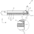
도 2는 본 발명의 하나의 실시예에 의한 비산방지필름이 합지된 슬림유리를 이용한 제1 디스플레이 부품(100)의 일부를 나타내는 단면도이다. FIG. 2 is a cross-sectional view showing a part of a
도 2에 의하면, 제1 디스플레이 부품(100)은 슬림유리(10) 및 비산방지필름(20)으로 이루어진다. 슬림유리(10)는 파편을 동반하지 않는 크랙이 일어나는 파손 메커니즘을 가진다. 비산하는 파편이 없고 날카로운 에지가 발생하지 않으므로, 사용자에게 자상과 상처를 입히거나, 인체 내부로 흡입되는 파편이 없다. 본 발명의 슬림유리(10)의 두께(T3)는 대략 10㎛~150㎛이다. 파손된 슬림유리(10)는 비산방지필름(20)에 붙어 있으므로, 안정성을 확보할 수 있다. 위의 조건을 만족하는 슬림유리(10)는 초박형 플렉시블 유리(super slim flexible glass)라고도 한다. 제1 디스플레이 부품(100)의 전체 두께(T4)를 가진다. 이러한 두께(T4)는 본 발명의 실시예에 적용되는 디스플레이 장치의 휘어지는 정도, 슬림유리(10)의 두께(T3) 등을 고려하여 적절하게 선택할 수 있다. 2, the
슬림유리(10)는 화학적으로 강화시킨 광학용 유리가 바람직하고, 각종 기능을 발현시키는 인쇄층을 포함할 수 있다. 상기 인쇄층은 투명, 반투명 또는 칼라 등 어느 하나 또는 어느 하나 이상의 코팅을 적용할 수 있다. 상기 인쇄층은 실크인쇄 또는 UV를 이용한 잉크젯 프린팅 또는 열경화를 이용한 잉크젯 프린팅 또는 전사를 이용하여 형성될 수 있다. 슬림유리(10) 상에는 지문방지, 반사방지, 청색광(blue light) 차단, 전자파 차단, 프라이버시(privacy), 항균성 등의 특성을 부여할 수 있다. 예를 들어, 불소계 코팅액이 습식 코팅되거나, 진공증착으로 건식 코팅하여 지문방지 기능을 부여하는 지문방지코팅층이 형성될 수 있다.이와 같이, 상기 코팅은 슬림유리(10)가 다양한 기능을 발현하도록 할 수 있다.The
경우에 따라, 슬림유리(10)에 인쇄층을 형성하는 대신에 비산방지필름(20)에 인쇄층을 형성할 수 있다. 다시 말해, 상기 인쇄층은 슬림유리(10) 또는 비산방지필름(20) 중의 어느 하나 또는 양쪽 모두에 형성할 수 있다. 이러한 인쇄층의 위치는 본 발명이 적용되는 디스플레이 장치의 형상, 기능 등에 따라 달라질 수 있다. 이렇게 되면, 상기 인쇄층에 구애받지 않고, 터치스크린 패널 화면의 크기 등을 보다 유연하게 조절할 수 있다.In some cases, a printing layer may be formed on the light-scattering
비산방지필름(20)은 투명 고분자 필름(22)의 일측은 투명 접착층(21)이 있고, 타측은 투명 점착층(23)이 도포된 것이다. 투명 고분자 필름(22)은 PET(PolyEthyleneTerephthalate), PEN(PolyEthyleneNaphthalate), PES(PolyetherSulfone), PI(PolyImide), PAR(PolyARylate), PC(PolyCarbonate), PMMA(PolyMethylMethAcrylate) 또는 COC(CycloOlefin Copolymer) 중 어느 하나 또는 어느 하나 이상로 이루어질 수 있다. 투명 접착층(21)은 아크릴계 수지, 실리콘계 수지 또는 우레탄계 수지인 열경화 수지 또는 자외선 경화형 수지에 가교제가 혼합된 점착제 또는 그들의 혼합물 또는 그들의 공중합체 중에 선택된 어느 하나로 이루어질 수 있으며, 투명 점착층(23)은 아크릴계 수지, 실리콘계 수지, 에폭시계 수지, 우레탄계 수지 또는 그들의 복합수지 중의 어느 하나로 이루어질 수 있다.The
한편, 비산방지필름(20)은 적용되는 상기 곡면 디스플레이 부품에 따라, 다른 구조를 가질 수 있다. 예를 들어, 상기 디스플레이 부품이 스마트폰의 윈도우이라면, 슬림유리(10)에 부착되는 비산방지필름(20)은 투명 점착층(23)이 없을 수 있다. 경우에 따라, 투명 점착층(23) 대신에, 예를 들어 투명한 접착층이 있을 수 있고, 다른 기능을 발현하는 층을 포함할 수 있다. 상기 디스플레이 부품이 스마트폰의 보호시트라면, 투명 점착층(23)을 필요로 할 것이다. On the other hand, the
비산방지필름(20)은 슬림유리 측면(10a)의 외측으로 폭(W)만큼 돌출되어 있다. 폭(W)은 대략 10㎛~100㎛이며, 본 발명의 범주 내에서 폭(W)의 크기를 다양하게 조절할 수 있다. 폭(W)에 대해서는, 추후에 최대접선을 중심으로 상세하게 살펴보기로 한다. 비산방지필름(20)의 단부는 레이저에 의해 절단되므로, 레이저 열에 의하여 변형된 열변형부(24)가 존재한다. 구체적으로, 상기 레이저가 비산방지필름(20)의 단부를 녹이면, 투명 접착층(21), 투명 고분자필름(22) 및 투명 점착층(23)이 용융되어 접착력을 상실한다. 열변형부(24)는 접착력이 없어지므로, 먼지와 같은 이물질이 부착되는 것을 차단한다. 열변형부(24)는 본 발명의 실시예에 의한 디스플레이 부품에 따라, 비산방지필름(20) 단부의 일부 또는 전부에 형성될 수 있다.The
열변형부(24)는 비산방지필름(20)의 두께를 얇게 하는 데 기여한다. 슬림유리 측면(10a)에 의한 자상을 방지하기 위하여, 비산방지필름(20)의 두께를 크게 하는 방안이 있을 수 있다. 이렇게 되면, 슬림유리(10)의 외부로 노출되는 비산방지필름(20)의 투명 접착층(21)의 두께가 커져서, 슬림유리 측면(10a) 근처에 끈적끈적한 층을 이루게 된다. 이러한 끈적끈적한 층에 먼지와 같은 이물질이 달라붙어 외관이 깨끗하지 않고, 상기 이물질은 합지하는 과정에서 발생하는 불량의 원인이 된다. 본 발명의 실시예에 의한 비산방지필름(20)은 앞에서 설명한 것보다 두께가 얇으므로, 투명 접착층(21)의 두께도 얇다. 투명 접착층(21)의 두께가 얇으면, 슬림유리(10)의 외부로 돌출된 투명 접착층(21) 및 투명 점착층(23)의 측면은 열변형부(24)로 덮여, 상기 이물질이 부착되는 것을 차단한다. The thermally
경우에 따라, 본 발명의 제1 디스플레이 부품(100)은 열변형부(24) 및 슬림유리(10)의 측면을 커버하는 보강밴드(30)를 더 형성할 수 있다. 보강밴드(30)를 슬림유리(10) 외측으로 폭(W)만큼 돌출된 비산방지필름(20)의 상면에 위치한다. 이때, 보강밴드(30)는 슬림유리(10)의 측면을 감싸듯이 둘레에 형성된다. 보강밴드(30)는 고분자 필름 또는 경화물질로 이루어질 수 있다. 상기 고분자 필름의 경우, 보강밴드(30)에 해당하는 부분을 열변형부(24)에 합지하여 형성할 수 있다. 보강밴드(30)는 슬림유리(10)와 동일한 평면을 이루거나, 슬림유리(10)의 일부를 덮을 수 있다. 도면에서는 상기 경화물질이 도포된 경우를 도시하였다.In some cases, the
상기 경화물질은 열 경화수지 또는 자외선 경화수지 중에 선택된 어느 하나의 경화수지로 이루어질 수 있으며, 자외선 경화수지가 보다 바람직하다. 예컨대 자외선 경화수지는 폴리우레탄 수지, 에폭시 수지 또는 폴리에스터 수지 등에 여러 가지의 아크릴 단위체와 자외선 경화 촉매를 배합해서 만든다. 자외선에 의한 경화물질의 구체적인 사례로써, 자외선 반응성 코팅물질로서 우레탄 또는 아크릴레이트 올리고머, 반응성 모노머, 광개시제 및 레벨링제를 혼합한다. 우레탄 아크릴레이트 올리고머는 지방족, 환상의 지방족, 방향족 화합물 또는 이들 화합물의 올리고머를 함유하고, 폴리에스테르 폴리올이나 폴리에테르 폴리올이 분자구조상에 포함되어 있는 화학식을 갖는다. The curing material may be any one selected from a thermosetting resin and an ultraviolet curing resin, and more preferably an ultraviolet curing resin. For example, an ultraviolet curing resin is prepared by blending various types of acrylic units and a UV curing catalyst such as a polyurethane resin, an epoxy resin or a polyester resin. As a specific example of the ultraviolet curing material, urethane or acrylate oligomer, reactive monomer, photoinitiator and leveling agent are mixed as an ultraviolet reactive coating material. The urethane acrylate oligomer has a formula containing an aliphatic, cyclic aliphatic, aromatic compound or an oligomer of these compounds, and polyester polyol or polyether polyol is included in the molecular structure.
반응성 모노머로는 트리메틸프로판 트리아크릴레이트, 헥산디올디아크를레이트, 펜타에리스티롤 트리아크릴레이트, 디펜타아릿티롤 헥사아크릴레이트를 경도 및 부착력을 고려하여 적당한 비율로 혼합하여 조절한다. 광개시제는 자외선에 의해 활성을 띠는 통상의 중합개시제를 사용하며, 특히 히드록시시클로헥실페닐케톤, 벤조페놀, 페닐-2-히드록시-2-페닐케톤을 주로 사용한다. 상기 경화물질에 의한 보강밴드(30)는 토출에 의한 도포 방식, 패드를 활용한 도포 방식, 디지털 인쇄에 의한 도포 방식 등을 활용하여 형성한다. As the reactive monomer, trimethylpropane triacrylate, hexane diol diacrylate, pentaerythritol triacrylate and dipentaerythritol hexaacrylate are mixed and adjusted at a suitable ratio in consideration of hardness and adhesive force. As the photoinitiator, a usual polymerization initiator which is activated by ultraviolet rays is used, and in particular, hydroxycyclohexyl phenyl ketone, benzophenol, and phenyl-2-hydroxy-2-phenylketone are mainly used. The reinforcing
보강밴드(30)는 비산방지필름(20)의 이물질에 대한 접착력을 제거하여 이물질 또는 먼지 등이 부착되는 것을 차단할 수 있다. 또한, 슬림유리(10) 및 비산방지필름(20) 사이의 단차를 줄여 사용자로 하여금 자상의 위험을 줄일 수 있다. 보강밴드(30)는 경도가 높고, 탄성도 우수하며, 장기간 써도 유해물질이 분해되어 나올 염려도 없다. 보강밴드(30)는 점착성을 가질 수 있으나, 점착성이 없는 것이 더욱 좋다. 점착성이 없으면, 외부의 이물질이 보강밴드(30)의 노출된 부분에 부착되지 않으므로, 제1 보호시트(100)의 미관을 해치지 않는다. 또한, 보강밴드(30)는 투명시트(10) 및 고분자 기재(20)의 단차를 줄이고, 투명시트(10)가 파손되는 것을 방지하여 제1 보호시트(100)의 안정성을 높인다.The reinforcing
한편, 슬림유리(10) 및 돌출된 비산방지필름(20)은 제1 최대접선[L(t1)]을 정의할 수 있 있다. 제1 최대접선[L(t1)]은 제1 디스플레이 부품(100)의 수평방향(x)에 대하여, 제1 최대각(θ1)을 가진 것이다. 이때, 제1 최대각(θ1)은 제1 디스플레이 부품(100)이 구현할 수 있는 최대 각도이다. 제1 최대접선[L(t1)] 및 제1 최대각(θ1)은 열변형부(24)의 형상 및 슬림유리(10)의 두께(T3) 및 폭(W)을 고려하여 사전에 시뮬레이션으로 설정된다. 제1 최대접선[L(t1)]은 슬림유리 측면(10a) 및 열변형부(24)가 동시에 접촉될 수 있는 접선이다. 따라서 제1 최대접선[L(t1)]으로 제1 디스플레이 부품(100)을 파지하면, 슬림유리 측면(10a) 및 열변형부(24)가 동시에 접촉된다.On the other hand, the
돌출된 폭(W)은 10㎛~100㎛이고, 슬림유리(10)의 두께(T3)는 10㎛~150㎛이므로, 제1 최대각(θ1)은 다음과 같이 결정된다. 즉, tanθ1=(T3/W)이며, 제1 최대각(θ1)의 최소값은 tanθ1=(10㎛/100㎛)로 정의되므로, 대략 6°정도이다. 또한, 제1 최대각(θ1)의 최대값은 tanθ1=(150㎛/10㎛)로 정의되므로, 대략 87°이다. 다시 말해, 본 발명의 실시예에 의한 제1 디스플레이 부품(100)의 제1 최대각(θ1)은 대략 6°내지 87°의 범위 내에 존재한다. Since the protruded width W is 10 占 퐉 to 100 占 퐉 and the thickness T3 of the
본 발명의 실시예에 의한 제1 디스플레이 부품(100)은 제1 최대각(θ1)보다 작은 접촉각을 가지는 것이 바람직하다. 상기 접촉각이 제1 최대각(θ1)보다 작으면, 슬림유리 측면(10a)은 제1 최대접선[L(t1)] 밖으로 벗어나지 않는다. 슬림유리 측면(10a)이 제1 최대접선[L(t1)]의 내측에 있으면, 사용자는 슬림유리 측면(10a)과는 접촉되지 않으면서, 비산방지필름(20)의 단부를 파지(把持)할 수 있다. 바람직한 접촉각은 제1 최대각(θ1)의 범위보다 작은 10°내지 80°가 좋다. 왜냐하면, 상기 접촉각은 비산방지필름(20)의 변형을 고려하여, 자상을 방지하는 신뢰도를 확보하기 위함이다. 이에 따라, 비산방지필름(20)은 슬림유리 측면(10a)이 사용자에게 자상과 같은 상처를 입히는 것을 방지한다. The
본 발명의 제1 디스플레이 부품(100)은 슬림유리(10)와 비산방지필름(20)을 합지함으로써, 플렉시블하고 터치감이 탁월하여 포스 터치와 플렉시블 디스플레이에 사용되고, 비산방지기능이 있으며, 슬림유리 측면(10a)에 의해 자상을 입는 것을 방지하고, 측면(10a) 방향의 충격으로 깨지는 것을 방지할 뿐만 아니라, 슬림유리(10)의 파손에 의한 파편이 발생되는 것을 최소로 하거나 차단할 수 있다. 이와 같이, 최소로 하거나 차단하는 것을 억제한다고 한다.The
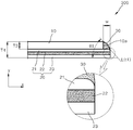
도 3은 본 발명의 다른 실시예에 의한 비산방지필름이 합지된 슬림유리를 이용한 제2 디스플레이 부품(200)의 일부를 나타내는 단면도이다. 이때, 제2 디스플레이 부품(200)은 단부가 라운딩된 슬림유리(12)를 적용한 것을 제외하고, 제1 디스플레이 부품(100)과 동일하다. 이에 따라, 중복된 부분에 대한 상세한 설명은 생략하기로 한다.3 is a cross-sectional view showing a part of a
도 3에 의하면, 제2 디스플레이 부품(200)은 라운딩 측면(12a)이 있는 슬림유리(12)를 채용한다. 라운딩된 측면(12a)에서, 라운딩된 형상은 다양하게 변형될 수 있다. 도면에서는, 슬림유리(12)의 상측 코너가 라운딩된 상태를 표현하였으나, 본 발명의 범주 내에서 다양하게 라운딩될 수 있다. 여기서, 상측 코너는 슬림유리(12)와 비산방지필름(20)이 접하는 하측에 대하여 수직방향(y)으로 대향하는 곳이다. 라운딩된 측면(12a)은 일정한 곡률을 가질 수 있으며, 곡률을 달리하면서 형성될 수 있다. 이와 같이, 라운딩된 형상 및 위치는 사용자에게 자상을 입히지 않게 하려는 본 발명의 범주 내에서 적절하게 조절될 수 있다.Referring to FIG. 3, the
제2 디스플레이 부품(200)은 슬림유리(12) 및 비산방지필름(20)은 제2 최대접선[L(t2)]을 정의할 수 있 있다. 제2 최대접선[L(t2)]은 제2 디스플레이 부품(200)의 수평방향(x)에 대하여, 제2 최대각(θ2)을 가진 것이다. 이때, 제2 최대각(θ2)은 제2 디스플레이 부품(200)이 구현할 수 있는 최대 각도이다. 제2 최대접선[L(t2)] 및 제2 최대각(θ2)은 열변형부(24)의 형상 및 슬림유리(12)의 두께(T3) 및 폭(W)을 고려하여 사전에 시뮬레이션으로 설정된다. 라운딩된 측면(12a)은 제2 최대접선[L(t2)] 및 제2 최대각(θ2)이 제1 디스플레이 부품(100)의 제1 최대접선[L(t1)] 및 제1 최대각(θ1)과는 달리 설정되도록 한다.The
본 발명의 실시예에 의한 제1 디스플레이 부품(100)은 제2 최대각(θ2)보다 작은 접촉각을 가지는 것이 바람직하다. 상기 접촉각이 제2 최대각(θ2)보다 작으면, 라운딩된 측면(12a)은 제2 최대접선[L(t2)] 밖으로 벗어나지 않는다. 라운딩된 측면(12a)이 제2 최대접선[L(t2)]의 내측에 있으면, 사용자는 라운딩된 측면(12a)과는 접촉되지 않으면서, 비산방지필름(20)의 단부를 파지(把持)할 수 있다. 바람직한 접촉각은 제1 최대각(θ1)의 경우와 마찬가지로, 제2 최대각(θ2)의 범위보다 작은 10°내지 80°가 좋다. 왜냐하면, 상기 접촉각은 비산방지필름(20)의 변형을 고려하여, 자상을 방지하는 신뢰도를 확보하기 위함이다. 이에 따라, 비산방지필름(20)은 라운딩된 측면(12a)이 사용자에게 자상과 같은 상처를 입히는 것을 방지한다. The
도 4는 본 발명의 또 다른 실시예에 의한 비산방지필름이 합지된 슬림유리를 이용한 제3 디스플레이 부품(300)의 일부를 나타내는 단면도이다. 이때, 제3 디스플레이 부품(300)은 열변형부(24)가 형성되지 않은 것을 제외하고, 제1 및 제2 디스플레이 부품(100, 200)과 동일하다. 이에 따라, 중복된 부분에 대한 상세한 설명은 생략하기로 한다.4 is a cross-sectional view showing a part of a
도 4에 의하면, 제3 디스플레이 부품(300)의 비산방지필름(20)은 열변형부(24)가 생성되지 않은 방법으로 절단된다. 상기 절단 방법은 에칭(etching), 샌드 블라스트(sand blast)와 같이 열을 사용하지 않는다. 이렇게 되면, 비산방지필름(20)의 단부에는 열변형부(24)가 형성되지 않는다. 본 발명의 제3 디스플레이 부품(300)은 비산방지필름(20)의 돌출된 부분 및 슬림유리(10)의 측면을 커버하는 보강밴드(30)을 더 형성할 수 있다. 이때, 보강밴드(30)는 도 2에서 설명한 것과 동일하다. 4, the
이하에서는 본 발명의 제1 내지 제3 디스플레이 부품(100, 200, 300)을 제조하는 방법을 설명하기로 한다. 설명의 편의를 위하여, 하나의 디스플레이 장치에 부착되는 디스플레이 부품을 디스플레이 부품 셀이라고 하고, 디스플레이 부품 셀을 구성하는 슬림유리는 슬림유리 셀, 비산방지필름은 비산방지필름 셀이라고 한다. 이때, 슬림유리 및 비산방지필름은 도 2 내지 도 4를 참조하기로 한다. Hereinafter, a method of manufacturing the first to
디스플레이 부품 셀을 제조하는 방법은 다양하다. 즉, 슬림유리 셀에 상기 슬림유리 셀보다 폭(W)만큼 돌출된 비산방지필름 셀을 합지하는 제1 방법, 슬림유리 셀에 폭(W)보다 크게 돌출된 비산방지필름을 합지하고, 비산방지필름을 폭(W)이 되도록 절단하여 비산방지필름 셀을 형성하는 제2 방법이 있다. 또한, 복수개의 슬림유리 셀을 수용할 수 있는 대면적 평탄 비산방지필름 또는 롤에 감긴 비산방지필름에 복수개의 슬림유리 셀을 합지하고, 각각의 슬림유리 셀에 대하여 비산방지필름이 폭(W)만큼 돌출되도록 절단하는 제3 방법이 있다. There are many ways to manufacture display part cells. That is, a first method of joining a light-scattering film cell protruding from a slim glass cell by a width (W) larger than the slim glass cell, a light scattering film projecting from the slim glass cell to a width larger than a width W, There is a second method of forming a light-scattering film cell by cutting the film so as to have a width (W). Also, a plurality of slim glass cells are laminated on a large-area flat-shaped anti-scattering film or a roll-wrapped anti-scattering film capable of accommodating a plurality of slim glass cells, and the anti- As shown in Fig.
위와 같은 제1 내지 제3 방법은 슬림유리를 셀 형태로 합지해야 하므로, 상술한 자상과 같은 상처를 유발할 위험이 있다. 또한, 슬림유리 셀과 비산방지필름(또는 비산방지필름 셀)을 합지하는 과정이 복잡하여, 대량생산에 적합하지 않다. 이하에서는 자상과 같은 상처를 유발하지 않고, 대량생산에 바람직한 제4 방법을 제시한다.The above-described first to third methods have a problem in that the slim glass must be laminated in a cell shape, which may cause scars such as the above-mentioned stab wound. Further, the process of laminating the slim glass cell and the light-scattering prevention film (or the light-scattering film cell) is complicated and is not suitable for mass production. Hereinafter, a fourth method which is preferable for mass production without inducing a wound such as a stab wound is presented.
도 5는 본 발명의 실시예에 의한 디스플레이 부품을 제조하는 방법을 설명하기 위한 흐름도이다. 5 is a flowchart for explaining a method of manufacturing a display part according to an embodiment of the present invention.
도 5에 의하면, 먼저, 대면적 평탄 유리 또는 롤(roll)에 감긴 유리를 대면적 평탄 비산방지필름 또는 롤(roll)에 감긴 비산방지필름을 합지한다(S10). 여기서, 대면적이란 복수개의 슬림유리 셀 및 비산방지필름 셀을 수용할 수 있는 정도의 면적이고, 평탄이란 롤에 감긴 것과는 달리 편평한 상태를 말한다. 합지하는 방법은 제한되지 않으며, 예컨대 롤러, 패드 등이 이용될 수 있다. 그후, 슬림유리 셀을 정의하는 마스크를 합지된 유리에 배치한다(S20). 마스크가 되지 않은 부분의 유리를 제거하여 슬림유리 셀을 형성한다(S30). 유리를 제거하면, 슬림유리 셀 및 비산방지필름이 잔존한다. 유리를 제거하는 방식은 다양하게 할 수 있으나, 식각액, 샌드 블라스트를 이용하는 식각 방식이 바람직하다. Referring to FIG. 5, first, a large-area flat glass or a glass wound on a roll is laminated with a large-area flat anti-scattering film or a anti-scattering film wrapped with a roll (S10). Here, the large area is an area enough to accommodate the plurality of slim glass cells and the scattering-prevention film cell, and the flatness refers to a flat state, unlike the case where the film is wound on the roll. The method of laminating is not limited, and for example, a roller, a pad, or the like may be used. Thereafter, a mask defining the slim glass cell is placed on the laminated glass (S20). The glass in the non-masked portion is removed to form a slim glass cell (S30). When the glass is removed, the slim glass cell and the anti-scattering film remain. The method of removing the glass can be various, but an etching method using an etching solution or a sandblast is preferable.
최종적으로, 슬림유리 셀의 외측으로 폭(W)만큼 돌출되도록 비산방지필름을 레이저로 절단하여, 비산방지필름이 합지된 슬림유리 셀을 형성한다(S40). 이때, 마스크는 식각 또는 레이저 절단 이후에 제거할 수 있다. 본 발명의 실시예에서 제시하는 제4 방법은 슬림유리 셀을 비산방지필름에 합지하는 과정이 없으므로, 합지하는 과정에서 발생하는 자상 등의 상처가 일어나지 않는다. 또한, 대면적 유리 및 비산방지필름을 합지한 후에, 슬림유리 셀 및 비산방지필름 셀을 순차적으로 형성하기 때문에, 공정이 간단하고 대량생산이 용이하다. 나아가, 마스크는 투명하지 않아도 되므로, 마스크를 비산방지필름 셀을 절단하기 위한 정렬수단으로 활용할 수 있다.Finally, the light-scattering film is cut with a laser so as to protrude to the outside of the slim glass cell by the width W, thereby forming a slim glass cell with the light-scattering film laminated (S40). At this time, the mask can be removed after etching or laser cutting. The fourth method proposed in the embodiment of the present invention does not involve the step of laminating the slim glass cell to the shatterproof film, so that a wound such as a staple generated during the laminating process does not occur. Further, since the slim glass cell and the scattering-prevention film cell are sequentially formed after laminating the large-area glass and the scattering-prevention film, the process is simple and mass production is easy. Furthermore, since the mask does not need to be transparent, the mask can be utilized as an alignment means for cutting the anti-scattering film cell.
이상, 본 발명은 바람직한 실시예를 들어 상세하게 설명하였으나, 본 발명은 상기 실시예에 한정되지 않으며, 본 발명의 기술적 사상의 범위 내에서 당 분야에서 통상의 지식을 가진 자에 의하여 여러 가지 변형이 가능하다. While the present invention has been particularly shown and described with reference to exemplary embodiments thereof, it is to be understood that the invention is not limited to the disclosed exemplary embodiments, but many variations and modifications may be made without departing from the spirit and scope of the invention. It is possible.
10, 12; 슬림유리
10a; 슬림유리 측면 12a; 라운딩된 측면
20; 비산방지필름 21; 투명 접착층
22; 투명 고분자 필름 23; 투명 점착층
24; 열변형부 30; 보강밴드
100, 200, 300; 제1 내지 제3 디스플레이 부품10, 12; Slim glass
10a;
20; A
22;
24; A
100, 200, 300; The first to third display parts
Claims (17)
상기 슬림유리의 일측에 합지되고, 상기 슬림유리의 외측으로 폭(W)만큼 돌출되며, 상기 슬림유리가 부착되는 투명 접착층 및 상기 투명 접착층에 접착된 투명 고분자 필름을 포함하는 비산방지필름을 포함하고,
상기 슬림유리와 상기 비산방지필름이 합지되어, 상기 슬림유리는 파편을 동반하지 않는 크랙이 일어나는 파손 메커니즘을 가져서 상기 파편의 발생이 억제되고, 상기 비산방지필름에 의해 상기 슬림유리의 측면 파손이 차단되는 것을 특징으로 하는 비산방지필름이 합지된 슬림유리를 이용한 디스플레이 부품.A flexible slim glass having a thickness of 10 mu m to 150 mu m; And
A scattering prevention film comprising a transparent adhesive layer laminated on one side of the slim glass and projecting outwardly of the slim glass by a width W and having the slim glass adhered thereto and a transparent polymer film adhered to the transparent adhesive layer, ,
Wherein the slim glass and the shrinkage preventing film are laminated so that the slim glass has a breakage mechanism in which cracks that do not accompany shards are generated so that generation of the shards is suppressed and side fouling of the slim glass is prevented And a display part using the slim glass having the anti-scattering film laminated thereon.
상기 슬림유리의 일측에 합지되고, 상기 슬림유리의 외측으로 폭(W)만큼 돌출되며, 상기 슬림유리가 부착되는 투명 접착층 및 상기 투명 접착층에 접착된 투명 고분자 필름을 포함하는 비산방지필름을 합지하는 단계를 포함하고,
상기 슬림유리와 상기 비산방지필름이 합지되어, 상기 슬림유리는 파편을 동반하지 않는 크랙이 일어나는 파손 메커니즘을 가져서 상기 파편의 발생이 억제되고, 상기 비산방지필름에 의해 상기 슬림유리의 측면 파손이 차단되는 것을 특징으로 하는 비산방지필름이 합지된 슬림유리를 이용한 디스플레이 부품을 제조하는 방법. Preparing a flexible slim glass having a thickness of 10 mu m to 150 mu m; And
And a transparent polymer film laminated on one side of the slim glass and projecting outwardly of the slim glass by a width W and having a transparent adhesive layer on which the slim glass is adhered and a transparent polymer film adhered on the transparent adhesive layer, ≪ / RTI >
Wherein the slim glass and the shrinkage preventing film are laminated so that the slim glass has a breakage mechanism in which cracks that do not accompany shards are generated so that generation of the shards is suppressed and side fouling of the slim glass is prevented Wherein the light shielding film is made of a transparent material.
슬림유리 셀을 정의하는 마스크를 상기 유리 상에 배치하는 단계;
상기 마스크의 형상대로 상기 마스크가 되지 않은 부분의 유리를 제거하여 상기 슬림유리 셀을 형성하는 단계; 및
상기 슬림유리 셀의 외측으로 폭(W)만큼 돌출되도록 상기 비산방지필름을 레이저로 절단하여, 비산방지필름이 합지된 슬림유리 셀을 형성하는 단계를 포함하는 비산방지필름이 합지된 슬림유리를 이용한 디스플레이 부품을 제조하는 방법. A method for manufacturing a light-scattering film, comprising the steps of: applying a flexible large-area flat glass or a roll-wound glass having a thickness of 10 to 150 占 퐉 to a large-area flat anti-scattering film or a anti-
Disposing a mask defining the slim glass cell on the glass;
Removing the unmasked portion of the glass in the shape of the mask to form the slim glass cell; And
And a step of forming a slim glass cell in which a shatterproof film is laminated by cutting the shatterproof film with a laser so as to protrude to the outside of the slim glass cell by a width W, A method of manufacturing a display component.
Applications Claiming Priority (2)
| Application Number | Priority Date | Filing Date | Title |
|---|---|---|---|
| KR1020160004984 | 2016-01-14 | ||
| KR20160004984 | 2016-01-14 |
Publications (1)
| Publication Number | Publication Date |
|---|---|
| KR20170085420A true KR20170085420A (en) | 2017-07-24 |
Family
ID=59429224
Family Applications (1)
| Application Number | Title | Priority Date | Filing Date |
|---|---|---|---|
| KR1020160071595A KR20170085420A (en) | 2016-01-14 | 2016-06-09 | Display components using slim glass adhered anti-scattering film and method of manufacturing the components |
Country Status (1)
| Country | Link |
|---|---|
| KR (1) | KR20170085420A (en) |
Cited By (3)
| Publication number | Priority date | Publication date | Assignee | Title |
|---|---|---|---|---|
| KR20190081337A (en) * | 2017-12-29 | 2019-07-09 | 엘지디스플레이 주식회사 | Foldable Display Having Step Stack Structure |
| US11073869B2 (en) | 2019-03-29 | 2021-07-27 | Samsung Electronics Co., Ltd. | Electronic device with coating for protection of window |
| US11586242B2 (en) | 2019-01-18 | 2023-02-21 | Samsung Display Co., Ltd. | Protection member for display device, display device including the same and method for fabricating protection member |
-
2016
- 2016-06-09 KR KR1020160071595A patent/KR20170085420A/en not_active Application Discontinuation
Cited By (4)
| Publication number | Priority date | Publication date | Assignee | Title |
|---|---|---|---|---|
| KR20190081337A (en) * | 2017-12-29 | 2019-07-09 | 엘지디스플레이 주식회사 | Foldable Display Having Step Stack Structure |
| US11586242B2 (en) | 2019-01-18 | 2023-02-21 | Samsung Display Co., Ltd. | Protection member for display device, display device including the same and method for fabricating protection member |
| US11073869B2 (en) | 2019-03-29 | 2021-07-27 | Samsung Electronics Co., Ltd. | Electronic device with coating for protection of window |
| US11485114B2 (en) | 2019-03-29 | 2022-11-01 | Samsung Electronics Co., Ltd. | Electronic device with coating for protection of window |
Similar Documents
| Publication | Publication Date | Title |
|---|---|---|
| CN109791449B (en) | Display device including minute projection for adjusting attachment and detachment and method of manufacturing the same | |
| KR101717507B1 (en) | Composite protecting sheet attached mobile device having curved shape and method of manufacturing the sheet | |
| KR101657136B1 (en) | Protecting sheet for touch screen panel having curved surface of edge part | |
| KR102111138B1 (en) | Manufacturing Method of Flexible Cover Window | |
| US20190346591A1 (en) | Replaceable cover lens for flexible display | |
| WO2005003822A1 (en) | Microstructured optical film and production process thereof | |
| US20220376205A1 (en) | Flexible display device and method for preparing the same | |
| JP6011316B2 (en) | Method for producing transparent face material with adhesive layer | |
| KR102146150B1 (en) | Apparatus of display having detachable pattern | |
| US20060132945A1 (en) | Microstructured optical film and production process thereof | |
| KR20170085420A (en) | Display components using slim glass adhered anti-scattering film and method of manufacturing the components | |
| TWI444289B (en) | And a method of manufacturing a liquid crystal display device for a liquid crystal display device | |
| EP3683785B1 (en) | Method for manufacturing transparent panel and method for manufacturing optical device | |
| KR101461611B1 (en) | window for protecting a panel, a portable terminal including the same and a manufacturing method of the same | |
| KR101798759B1 (en) | Protecting sheet module attached mobile device having curved shape, method of manufacturing the sheet using the module and sheet manufactured by the method | |
| US11413849B2 (en) | Transparent member having fine uneven portions and applied to portable device | |
| KR20180000822A (en) | Protecting sheet attached display device having curved shape | |
| KR101769014B1 (en) | Anti-scattering parts attached display device having curved shape and method of attaching the parts | |
| KR101970109B1 (en) | Transparent parts having micro protrusion applying mobile display | |
| KR20180073420A (en) | Curved mobile device for attaching protecting sheet | |
| CN111386479A (en) | Detachable display device including polarizing film | |
| KR101713433B1 (en) | Protecting sheet for touch screen panel attached safety film and method of manufacturing the sheet | |
| JP2010090344A (en) | Method for manufacturing double-coated adhesive tape, display, and bonded substrate and method of manufacturing display | |
| KR102501292B1 (en) | Flexible Cover Window | |
| KR102549675B1 (en) | Flexible Cover Window with Improved Strength |
Legal Events
| Date | Code | Title | Description |
|---|---|---|---|
| A201 | Request for examination | ||
| E902 | Notification of reason for refusal | ||
| E601 | Decision to refuse application |