KR20170083608A - Multi-Functional Fecal Waste and Garbage Processor and Associated Methods - Google Patents
Multi-Functional Fecal Waste and Garbage Processor and Associated Methods Download PDFInfo
- Publication number
- KR20170083608A KR20170083608A KR1020177016206A KR20177016206A KR20170083608A KR 20170083608 A KR20170083608 A KR 20170083608A KR 1020177016206 A KR1020177016206 A KR 1020177016206A KR 20177016206 A KR20177016206 A KR 20177016206A KR 20170083608 A KR20170083608 A KR 20170083608A
- Authority
- KR
- South Korea
- Prior art keywords
- sludge
- dryer
- steam
- fuel
- assembly
- Prior art date
Links
Images


Classifications
-
- F—MECHANICAL ENGINEERING; LIGHTING; HEATING; WEAPONS; BLASTING
- F01—MACHINES OR ENGINES IN GENERAL; ENGINE PLANTS IN GENERAL; STEAM ENGINES
- F01K—STEAM ENGINE PLANTS; STEAM ACCUMULATORS; ENGINE PLANTS NOT OTHERWISE PROVIDED FOR; ENGINES USING SPECIAL WORKING FLUIDS OR CYCLES
- F01K25/00—Plants or engines characterised by use of special working fluids, not otherwise provided for; Plants operating in closed cycles and not otherwise provided for
- F01K25/04—Plants or engines characterised by use of special working fluids, not otherwise provided for; Plants operating in closed cycles and not otherwise provided for the fluid being in different phases, e.g. foamed
-
- B—PERFORMING OPERATIONS; TRANSPORTING
- B01—PHYSICAL OR CHEMICAL PROCESSES OR APPARATUS IN GENERAL
- B01D—SEPARATION
- B01D1/00—Evaporating
- B01D1/04—Evaporators with horizontal tubes
-
- B—PERFORMING OPERATIONS; TRANSPORTING
- B01—PHYSICAL OR CHEMICAL PROCESSES OR APPARATUS IN GENERAL
- B01D—SEPARATION
- B01D1/00—Evaporating
- B01D1/22—Evaporating by bringing a thin layer of the liquid into contact with a heated surface
- B01D1/222—In rotating vessels; vessels with movable parts
- B01D1/223—In rotating vessels; vessels with movable parts containing a rotor
- B01D1/225—In rotating vessels; vessels with movable parts containing a rotor with blades or scrapers
- B01D1/226—In rotating vessels; vessels with movable parts containing a rotor with blades or scrapers in the form of a screw or with helical blade members
-
- C—CHEMISTRY; METALLURGY
- C02—TREATMENT OF WATER, WASTE WATER, SEWAGE, OR SLUDGE
- C02F—TREATMENT OF WATER, WASTE WATER, SEWAGE, OR SLUDGE
- C02F1/00—Treatment of water, waste water, or sewage
- C02F1/001—Processes for the treatment of water whereby the filtration technique is of importance
- C02F1/004—Processes for the treatment of water whereby the filtration technique is of importance using large scale industrial sized filters
-
- C—CHEMISTRY; METALLURGY
- C02—TREATMENT OF WATER, WASTE WATER, SEWAGE, OR SLUDGE
- C02F—TREATMENT OF WATER, WASTE WATER, SEWAGE, OR SLUDGE
- C02F11/00—Treatment of sludge; Devices therefor
- C02F11/12—Treatment of sludge; Devices therefor by de-watering, drying or thickening
-
- C—CHEMISTRY; METALLURGY
- C02—TREATMENT OF WATER, WASTE WATER, SEWAGE, OR SLUDGE
- C02F—TREATMENT OF WATER, WASTE WATER, SEWAGE, OR SLUDGE
- C02F11/00—Treatment of sludge; Devices therefor
- C02F11/12—Treatment of sludge; Devices therefor by de-watering, drying or thickening
- C02F11/13—Treatment of sludge; Devices therefor by de-watering, drying or thickening by heating
-
- C—CHEMISTRY; METALLURGY
- C02—TREATMENT OF WATER, WASTE WATER, SEWAGE, OR SLUDGE
- C02F—TREATMENT OF WATER, WASTE WATER, SEWAGE, OR SLUDGE
- C02F3/00—Biological treatment of water, waste water, or sewage
- C02F3/02—Aerobic processes
-
- C—CHEMISTRY; METALLURGY
- C02—TREATMENT OF WATER, WASTE WATER, SEWAGE, OR SLUDGE
- C02F—TREATMENT OF WATER, WASTE WATER, SEWAGE, OR SLUDGE
- C02F9/00—Multistage treatment of water, waste water or sewage
-
- F—MECHANICAL ENGINEERING; LIGHTING; HEATING; WEAPONS; BLASTING
- F01—MACHINES OR ENGINES IN GENERAL; ENGINE PLANTS IN GENERAL; STEAM ENGINES
- F01K—STEAM ENGINE PLANTS; STEAM ACCUMULATORS; ENGINE PLANTS NOT OTHERWISE PROVIDED FOR; ENGINES USING SPECIAL WORKING FLUIDS OR CYCLES
- F01K17/00—Using steam or condensate extracted or exhausted from steam engine plant
- F01K17/04—Using steam or condensate extracted or exhausted from steam engine plant for specific purposes other than heating
-
- F—MECHANICAL ENGINEERING; LIGHTING; HEATING; WEAPONS; BLASTING
- F01—MACHINES OR ENGINES IN GENERAL; ENGINE PLANTS IN GENERAL; STEAM ENGINES
- F01K—STEAM ENGINE PLANTS; STEAM ACCUMULATORS; ENGINE PLANTS NOT OTHERWISE PROVIDED FOR; ENGINES USING SPECIAL WORKING FLUIDS OR CYCLES
- F01K17/00—Using steam or condensate extracted or exhausted from steam engine plant
- F01K17/06—Returning energy of steam, in exchanged form, to process, e.g. use of exhaust steam for drying solid fuel or plant
-
- F—MECHANICAL ENGINEERING; LIGHTING; HEATING; WEAPONS; BLASTING
- F22—STEAM GENERATION
- F22B—METHODS OF STEAM GENERATION; STEAM BOILERS
- F22B31/00—Modifications of boiler construction, or of tube systems, dependent on installation of combustion apparatus; Arrangements of dispositions of combustion apparatus
- F22B31/0007—Modifications of boiler construction, or of tube systems, dependent on installation of combustion apparatus; Arrangements of dispositions of combustion apparatus with combustion in a fluidized bed
-
- F—MECHANICAL ENGINEERING; LIGHTING; HEATING; WEAPONS; BLASTING
- F23—COMBUSTION APPARATUS; COMBUSTION PROCESSES
- F23G—CREMATION FURNACES; CONSUMING WASTE PRODUCTS BY COMBUSTION
- F23G5/00—Incineration of waste; Incinerator constructions; Details, accessories or control therefor
- F23G5/02—Incineration of waste; Incinerator constructions; Details, accessories or control therefor with pretreatment
- F23G5/04—Incineration of waste; Incinerator constructions; Details, accessories or control therefor with pretreatment drying
-
- F—MECHANICAL ENGINEERING; LIGHTING; HEATING; WEAPONS; BLASTING
- F23—COMBUSTION APPARATUS; COMBUSTION PROCESSES
- F23G—CREMATION FURNACES; CONSUMING WASTE PRODUCTS BY COMBUSTION
- F23G5/00—Incineration of waste; Incinerator constructions; Details, accessories or control therefor
- F23G5/30—Incineration of waste; Incinerator constructions; Details, accessories or control therefor having a fluidised bed
-
- F—MECHANICAL ENGINEERING; LIGHTING; HEATING; WEAPONS; BLASTING
- F23—COMBUSTION APPARATUS; COMBUSTION PROCESSES
- F23G—CREMATION FURNACES; CONSUMING WASTE PRODUCTS BY COMBUSTION
- F23G5/00—Incineration of waste; Incinerator constructions; Details, accessories or control therefor
- F23G5/40—Portable or mobile incinerators
-
- F—MECHANICAL ENGINEERING; LIGHTING; HEATING; WEAPONS; BLASTING
- F23—COMBUSTION APPARATUS; COMBUSTION PROCESSES
- F23K—FEEDING FUEL TO COMBUSTION APPARATUS
- F23K1/00—Preparation of lump or pulverulent fuel in readiness for delivery to combustion apparatus
- F23K1/04—Heating fuel prior to delivery to combustion apparatus
-
- C—CHEMISTRY; METALLURGY
- C02—TREATMENT OF WATER, WASTE WATER, SEWAGE, OR SLUDGE
- C02F—TREATMENT OF WATER, WASTE WATER, SEWAGE, OR SLUDGE
- C02F1/00—Treatment of water, waste water, or sewage
- C02F1/001—Processes for the treatment of water whereby the filtration technique is of importance
-
- C—CHEMISTRY; METALLURGY
- C02—TREATMENT OF WATER, WASTE WATER, SEWAGE, OR SLUDGE
- C02F—TREATMENT OF WATER, WASTE WATER, SEWAGE, OR SLUDGE
- C02F1/00—Treatment of water, waste water, or sewage
- C02F1/02—Treatment of water, waste water, or sewage by heating
- C02F1/04—Treatment of water, waste water, or sewage by heating by distillation or evaporation
-
- C—CHEMISTRY; METALLURGY
- C02—TREATMENT OF WATER, WASTE WATER, SEWAGE, OR SLUDGE
- C02F—TREATMENT OF WATER, WASTE WATER, SEWAGE, OR SLUDGE
- C02F1/00—Treatment of water, waste water, or sewage
- C02F1/20—Treatment of water, waste water, or sewage by degassing, i.e. liberation of dissolved gases
-
- C—CHEMISTRY; METALLURGY
- C02—TREATMENT OF WATER, WASTE WATER, SEWAGE, OR SLUDGE
- C02F—TREATMENT OF WATER, WASTE WATER, SEWAGE, OR SLUDGE
- C02F1/00—Treatment of water, waste water, or sewage
- C02F1/28—Treatment of water, waste water, or sewage by sorption
- C02F1/283—Treatment of water, waste water, or sewage by sorption using coal, charred products, or inorganic mixtures containing them
-
- C—CHEMISTRY; METALLURGY
- C02—TREATMENT OF WATER, WASTE WATER, SEWAGE, OR SLUDGE
- C02F—TREATMENT OF WATER, WASTE WATER, SEWAGE, OR SLUDGE
- C02F1/00—Treatment of water, waste water, or sewage
- C02F1/44—Treatment of water, waste water, or sewage by dialysis, osmosis or reverse osmosis
- C02F1/444—Treatment of water, waste water, or sewage by dialysis, osmosis or reverse osmosis by ultrafiltration or microfiltration
-
- C—CHEMISTRY; METALLURGY
- C02—TREATMENT OF WATER, WASTE WATER, SEWAGE, OR SLUDGE
- C02F—TREATMENT OF WATER, WASTE WATER, SEWAGE, OR SLUDGE
- C02F11/00—Treatment of sludge; Devices therefor
- C02F11/06—Treatment of sludge; Devices therefor by oxidation
-
- C—CHEMISTRY; METALLURGY
- C02—TREATMENT OF WATER, WASTE WATER, SEWAGE, OR SLUDGE
- C02F—TREATMENT OF WATER, WASTE WATER, SEWAGE, OR SLUDGE
- C02F2101/00—Nature of the contaminant
- C02F2101/30—Organic compounds
-
- C—CHEMISTRY; METALLURGY
- C02—TREATMENT OF WATER, WASTE WATER, SEWAGE, OR SLUDGE
- C02F—TREATMENT OF WATER, WASTE WATER, SEWAGE, OR SLUDGE
- C02F2303/00—Specific treatment goals
- C02F2303/06—Sludge reduction, e.g. by lysis
-
- C—CHEMISTRY; METALLURGY
- C02—TREATMENT OF WATER, WASTE WATER, SEWAGE, OR SLUDGE
- C02F—TREATMENT OF WATER, WASTE WATER, SEWAGE, OR SLUDGE
- C02F2303/00—Specific treatment goals
- C02F2303/10—Energy recovery
-
- F—MECHANICAL ENGINEERING; LIGHTING; HEATING; WEAPONS; BLASTING
- F23—COMBUSTION APPARATUS; COMBUSTION PROCESSES
- F23K—FEEDING FUEL TO COMBUSTION APPARATUS
- F23K2201/00—Pretreatment of solid fuel
- F23K2201/20—Drying
-
- Y—GENERAL TAGGING OF NEW TECHNOLOGICAL DEVELOPMENTS; GENERAL TAGGING OF CROSS-SECTIONAL TECHNOLOGIES SPANNING OVER SEVERAL SECTIONS OF THE IPC; TECHNICAL SUBJECTS COVERED BY FORMER USPC CROSS-REFERENCE ART COLLECTIONS [XRACs] AND DIGESTS
- Y02—TECHNOLOGIES OR APPLICATIONS FOR MITIGATION OR ADAPTATION AGAINST CLIMATE CHANGE
- Y02E—REDUCTION OF GREENHOUSE GAS [GHG] EMISSIONS, RELATED TO ENERGY GENERATION, TRANSMISSION OR DISTRIBUTION
- Y02E20/00—Combustion technologies with mitigation potential
- Y02E20/12—Heat utilisation in combustion or incineration of waste
-
- Y—GENERAL TAGGING OF NEW TECHNOLOGICAL DEVELOPMENTS; GENERAL TAGGING OF CROSS-SECTIONAL TECHNOLOGIES SPANNING OVER SEVERAL SECTIONS OF THE IPC; TECHNICAL SUBJECTS COVERED BY FORMER USPC CROSS-REFERENCE ART COLLECTIONS [XRACs] AND DIGESTS
- Y02—TECHNOLOGIES OR APPLICATIONS FOR MITIGATION OR ADAPTATION AGAINST CLIMATE CHANGE
- Y02E—REDUCTION OF GREENHOUSE GAS [GHG] EMISSIONS, RELATED TO ENERGY GENERATION, TRANSMISSION OR DISTRIBUTION
- Y02E50/00—Technologies for the production of fuel of non-fossil origin
- Y02E50/10—Biofuels, e.g. bio-diesel
-
- Y—GENERAL TAGGING OF NEW TECHNOLOGICAL DEVELOPMENTS; GENERAL TAGGING OF CROSS-SECTIONAL TECHNOLOGIES SPANNING OVER SEVERAL SECTIONS OF THE IPC; TECHNICAL SUBJECTS COVERED BY FORMER USPC CROSS-REFERENCE ART COLLECTIONS [XRACs] AND DIGESTS
- Y02—TECHNOLOGIES OR APPLICATIONS FOR MITIGATION OR ADAPTATION AGAINST CLIMATE CHANGE
- Y02E—REDUCTION OF GREENHOUSE GAS [GHG] EMISSIONS, RELATED TO ENERGY GENERATION, TRANSMISSION OR DISTRIBUTION
- Y02E50/00—Technologies for the production of fuel of non-fossil origin
- Y02E50/30—Fuel from waste, e.g. synthetic alcohol or diesel
-
- Y—GENERAL TAGGING OF NEW TECHNOLOGICAL DEVELOPMENTS; GENERAL TAGGING OF CROSS-SECTIONAL TECHNOLOGIES SPANNING OVER SEVERAL SECTIONS OF THE IPC; TECHNICAL SUBJECTS COVERED BY FORMER USPC CROSS-REFERENCE ART COLLECTIONS [XRACs] AND DIGESTS
- Y02—TECHNOLOGIES OR APPLICATIONS FOR MITIGATION OR ADAPTATION AGAINST CLIMATE CHANGE
- Y02W—CLIMATE CHANGE MITIGATION TECHNOLOGIES RELATED TO WASTEWATER TREATMENT OR WASTE MANAGEMENT
- Y02W10/00—Technologies for wastewater treatment
- Y02W10/30—Wastewater or sewage treatment systems using renewable energies
-
- Y—GENERAL TAGGING OF NEW TECHNOLOGICAL DEVELOPMENTS; GENERAL TAGGING OF CROSS-SECTIONAL TECHNOLOGIES SPANNING OVER SEVERAL SECTIONS OF THE IPC; TECHNICAL SUBJECTS COVERED BY FORMER USPC CROSS-REFERENCE ART COLLECTIONS [XRACs] AND DIGESTS
- Y02—TECHNOLOGIES OR APPLICATIONS FOR MITIGATION OR ADAPTATION AGAINST CLIMATE CHANGE
- Y02W—CLIMATE CHANGE MITIGATION TECHNOLOGIES RELATED TO WASTEWATER TREATMENT OR WASTE MANAGEMENT
- Y02W10/00—Technologies for wastewater treatment
- Y02W10/40—Valorisation of by-products of wastewater, sewage or sludge processing
Abstract
이 기술의 적어도 하나의 양태는 배설물 슬러지 및 쓰레기와 같은 유기성 고수분 함유 폐기물을 전기로 전환하면서 음료수를 생성 및 수집하는 자급식 처리 설비를 제공한다.At least one aspect of the technique provides a self-contained treatment facility that generates and collects drinking water while converting organic high moisture content wastes such as waste sludge and refuse to electricity.
Description
본 기술은 다기능 배설물 폐기물 및 쓰레기 처리 시스템, 장비 및 관련 방법에 관한 것이다.The present technology relates to multifunctional fecal waste and garbage disposal systems, equipment and related methods.
세계의 많은 지역은 인간의 폐기물 및 다른 쓰레기를 처리하기 위한 개방형 위생 시스템을 이용하는 반면, 다른 지역은 미처리 하수를 개방 배수 또는 표층수로 배출하는 미흡한 정화조 시스템 또는 다른 시스템을 이용한다. 이러한 열악한 위생 조건은 이런 지역에서 건강 문제의 전조가 되는 데 기여한다. 부적절한 위생 시스템을 가진 이런 많은 지역은 또한 청결한 음료수를 유지하는 데 어려움을 겪으며, 이는 잠재적인 건강 문제를 더욱 증가시킨다. 이런 지역은 종종 전기를 생산하는데 이용하기 위한 제한된 자원을 가지거나 전기를 생산하기 위한 비용이 엄청나게 비싸다. Many parts of the world use open sanitary systems to treat human waste and other wastes, while others use poorly septic systems or other systems that discharge untreated sewage to open drainage or surface waters. These poor hygiene conditions contribute to becoming a precursor to health problems in these areas. Many of these areas with inadequate sanitation systems also have difficulty maintaining clean drinking water, which further increases potential health problems. These areas often have limited resources to use to produce electricity or the cost of producing electricity is prohibitively high.
따라서, 청결한 음료수에 대한 접근을 제공하고 유지하며, 저렴한 전기를 생성하기 위해 환경으로부터 폐기물을 제거하는 적절한 위생 시스템이 필요하다.Therefore, there is a need for a proper sanitary system to provide and maintain access to clean drinking water, and to remove waste from the environment to produce inexpensive electricity.
본 기술은 종래 기술에서 경험한 결점을 극복하고 부가적인 이점을 제공하는 방식으로 폐기물을 처리하면서 전기 및 음료수를 생성하기 위한 다기능 시스템을 제공한다. 이 기술의 적어도 하나의 양태는 배설물 슬러지 및 쓰레기와 같은 유기성, 고수분 함유 폐기물을 전기로 전환하면서 음료수를 생성하고 수집하도록 구성된 자급식 처리 설비를 제공한다.The present technology provides a multifunctional system for generating electricity and beverages while treating waste in a manner that overcomes the drawbacks experienced in the prior art and provides additional benefits. At least one aspect of the technique provides a self-contained treatment facility configured to generate and collect drinking water while converting organic, highly water containing waste, such as waste sludge and waste, into electricity.
본 발명의 내용 중에 포함되어 있다.Are included in the scope of the present invention.
본 기술의 많은 양태는 다음의 도면을 참조하면 더 잘 이해될 수 있다. 도면의 구성요소는 반드시 일정한 축척을 가질 필요는 없다. 대신, 현재 기술의 원리를 명확하게 설명하는데 중점을 둔다. 참조의 용이함을 위해, 본 발명 전반에 걸쳐 동일한 참조번호는 동일하거나 적어도 일반적으로 유사하거나 유사한 구성요소 또는 특징을 식별하는데 사용될 수 있다.
도 1은 본 기술의 한 실시태양에 따른 다기능 폐기물 처리 시스템의 구성요소의 개략적인 흐름도이다.
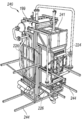
도 2는 도 1의 다기능 폐기물 처리 시스템의 등각투상도이다.
도 3은 본 기술의 한 양태에 따른 슬러지 보유 및 전달 시스템의 등각투상도이다.
도 4는 슬러지 보유 및 운반 시스템의 한 실시태양의 인-피드 어셈블리(in-feed assembly)의 등각투상도이다.
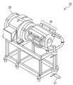
도 5는 도 2의 어셈블리로부터 분리된 슬러지 건조기 어셈블리의 등각투상도이다.
도 6은 도 4의 인-피드 어셈블리의 컨베이어 어셈블리에 연결된 슬러지 건조기 어셈블리의 단부의 확대 부분 등각투상도이다.
도 7은 도 5의 슬러지 건조기 어셈블리에서 처리 동안 슬러지 흐름의 개략적 인 등각투상도이다.
도 8은 슬러지의 흐름을 포함하는 스팀 가열된 홈에 회전 가능하게 위치된 스팀 가열된 오거(auger)를 갖는 슬러지 건조기 어셈블리의 부분 등각투상도이다.
도 9는 도 8의 오거로부터 분리되어 도시된 홈의 확대 등각투상도이다.
도 10은 도 8의 홈으로부터 분리되어 도시된 오거의 확대 등각투상도이다.
도 11은 슬러지의 흐름을 포함하는 증기 가열된 홈에 회전 가능하게 위치된 증기 가열된 오거 부재를 갖는 다른 실시태양의 슬러지 건조기 어셈블리의 부분 등각투상도이다.
도 12는 도 11의 홈으로부터 분리되어 도시된 증기 가열된 오거의 확대 등각투상도이다.
도 13a 및 도 13b는 본 기술의 실시태양에 따른 고압, 1단 슬러지 건조기 어셈블리의 등각투상도이다.
도 14는 본 기술의 실시태양에 따른 2단 슬러지 건조 시스템의 개략적인 흐름도이다.
도 15는 도 1의 폐기물 처리 시스템의 음료수 처리 시스템의 개략적인 흐름도이다.
도 16은 도 1의 폐기물 처리 시스템의 다른 실시태양의 음료수 처리 시스템의 개략적인 흐름도이다.
도 17은 도 5의 슬러지 건조기 어셈블리에 부착된 건조 연료 저장소 어셈블리의 등각투상도이다.
도 18은 슬러지 건조기 어셈블리로부터 제거되어 도시된 도 17의 건조 연료 저장소 어셈블리의 확대 부분 투명 등각투상도이다.
도 19는 도 1의 시스템에서 유동층 연소기에 부착된 도 18의 건조 연료 저장소 어셈블리의 개략적인 측면도이다.
도 20은 도 19의 유동층 연소기의 화실 및 배출 저장소의 부분 절결 등각투상도이다.
도 21은 도 20의 화실로부터 분리되어 도시된 연소 공기 압축기 및 인-라인 버너 어셈블리의 확대 등각투상도이다.
도 22는 도 20의 화실로부터 분리되어 도시된 공기 분배 화격자의 확대 등각 투상도이다.
도 23은 보일러를 통과하는 가열된 배기 가스 경로를 도시하는 도 1의 시스템의 건조 연료 연소기 및 보일러의 확대된, 부분적으로 절결된 등각투상도이다.
도 24는 도 23의 건조 연료 연소기로부터 분리되어 도시된 절약기 하우징(economizer housing) 및 다중-클론 어셈블리의 확대 부분 등각투상도이다.
도 25는 도 23의 건조 연료 연소기 어셈블리로부터 분리되어 도시된 절약기 하우징 및 애쉬 오거의 확대 부분 등각투상도이다.
도 26은 보일러를 통과하는 1차 수로를 도시하는 도 23의 건조 연료 연소기 및 보일러 어셈블리의 확대 부분 절결 등각투상도이다.
도 27은 다른 실시태양의 보일러의 배관 구성요소의 부분 절결 등각투상도이다.
도 28은 다른 실시태양에 따른 유동층 연소기 및 보일러의 등각투상도이며, 모듈식 보일러 구성요소는 개방된 노출 위치에 도시된다.
도 29는 도 28의 유동층 연소기 및 보일러의 등각투상도이며, 모듈식 보일러 구성요소는 적재된 작동 위치에 도시된다.
도 30은 도 1의 시스템으로부터 분리되어 도시된 증기 엔진 및 발전기를 구비한 발전소 어셈블리의 등각투상도이다.
도 31은 본 기술의 한 실시태양에 따른 캠 샤프트, 캠, 로커 암 및 밸브 트레인을 구비한 엔진 헤드 어셈블리의 부분 절개 확대 상부 등각투상도이다.
도 32는 흡기 캠, 흡기 및 배기 밸브, 및 관련된 로커 암을 구비한 도 31의 증기 엔진의 헤드 어셈블리의 확대 부분 단면의 등각투상도이다.
도 33은 도 31의 33-33 선을 실질적으로 따라 취한 증기 엔진의 헤드 어셈블리의 확대 단면도이다.
부록 A는 현재 기술의 양태에 관한 부가적인 정보 및 계산을 포함한다.Many aspects of the present technique may be better understood with reference to the following drawings. The components of the drawings do not necessarily have to have a constant scale. Instead, we focus on clearly explaining the principles of current technology. For ease of reference, the same reference numbers throughout the present invention may be used to identify the same or at least generally similar or similar elements or features.
1 is a schematic flow diagram of the components of a multifunctional waste treatment system according to one embodiment of the present technique.
Figure 2 is an isometric view of the multifunctional waste treatment system of Figure 1;
3 is an isometric view of a sludge retention and delivery system in accordance with an aspect of the technology.
4 is an isometric view of an in-feed assembly of one embodiment of a sludge retention and delivery system.
Figure 5 is an isometric view of a sludge dryer assembly separated from the assembly of Figure 2;
Figure 6 is an enlarged partial isometric view of the end of the sludge dryer assembly connected to the conveyor assembly of the in-feed assembly of Figure 4;
Figure 7 is a schematic isometric view of the sludge flow during processing in the sludge dryer assembly of Figure 5;
8 is a partial isometric view of a sludge dryer assembly having a steam-heated auger rotatably positioned in a steam-heated groove comprising a flow of sludge.
9 is an enlarged isometric view of the groove shown separated from the auger of Fig.
10 is an enlarged isometric view of the auger shown separated from the groove of Fig.
11 is a partial isometric view of a sludge dryer assembly of another embodiment having a vapor-heated auger member rotatably positioned in a vapor-heated groove comprising a flow of sludge;
12 is an enlarged isometric view of the steam-heated auger shown separated from the groove of Fig.
13A and 13B are isometric views of a high pressure, one-stage sludge dryer assembly in accordance with an embodiment of the present technology.
14 is a schematic flow diagram of a two-stage sludge drying system according to an embodiment of the present technique.
Figure 15 is a schematic flow diagram of a beverage processing system of the waste treatment system of Figure 1;
Figure 16 is a schematic flow diagram of a beverage processing system in another embodiment of the waste treatment system of Figure 1;
Figure 17 is an isometric view of a dry fuel storage assembly attached to the sludge dryer assembly of Figure 5;
Figure 18 is an enlarged partial transparent isometric view of the dry fuel storage assembly of Figure 17 shown removed from the sludge dryer assembly.
Figure 19 is a schematic side view of the dry fuel storage assembly of Figure 18 attached to a fluid bed combustor in the system of Figure 1;
FIG. 20 is a partially cut isometric view of the firebox and discharge reservoir of the fluidized bed combustor of FIG. 19;
21 is an enlarged isometric view of the combustion air compressor and in-line burner assembly shown separated from the firebox of FIG.
22 is an enlarged isometric view of the air distribution grate shown separately from the artificial chamber of Fig.
Figure 23 is an enlarged, partially cut isometric view of the dry fuel combustor and boiler of the system of Figure 1 showing the heated exhaust gas path through the boiler.
24 is an enlarged partial isometric view of the economizer housing and multi-clone assembly shown separated from the dry fuel combustor of FIG.
Figure 25 is an enlarged partial isometric view of the economizer housing and ashger shown separately from the dry fuel combustor assembly of Figure 23;
Figure 26 is an enlarged, partially cut away isometric view of the dry fuel combustor and boiler assembly of Figure 23 showing the primary channel through the boiler.
Figure 27 is a partially cut isometric view of the piping components of the boiler of another embodiment.
Fig. 28 is an isometric view of a fluidized bed combustor and boiler according to another embodiment, and the modular boiler component is shown in an open exposure position.
FIG. 29 is an isometric view of the fluidized bed combustor and boiler of FIG. 28, and the modular boiler component is shown in the loaded operating position.
30 is an isometric view of a power plant assembly with a steam engine and a generator shown separately from the system of FIG.
31 is a partially cut-enlarged upper isometric view of an engine head assembly having a camshaft, a cam, a rocker arm, and a valve train according to one embodiment of the present technology.
32 is an isometric view of an enlarged partial cross section of the head assembly of the steam engine of FIG. 31 with an intake cam, an intake and exhaust valve, and an associated rocker arm;
33 is an enlarged cross-sectional view of the head assembly of the steam engine taken substantially along line 33-33 of Fig.
Annex A contains additional information and calculations relating to aspects of the current technology.
본 발명은 본 기술의 특정 실시태양에 따라 전기 및 음료수를 생성하도록 구성된 다기능 폐기물 처리 시스템을 기술한다. 이 기술의 몇몇 특정 세부 사항은 본 기술의 특정 실시태양에 대한 완전한 이해를 제공하기 위해 다음의 설명 및 도 1 내지 도 33에 제시된다. 그러나, 당업자는 본 기술이 부가적인 실시태양을 가질 수 있고 기술의 다른 실시태양은 아래에서 설명되는 몇몇 특정 특징이 없이 실시될 수 있음을 이해할 것이다.The present invention describes a multifunctional waste treatment system configured to produce electricity and beverages in accordance with certain embodiments of the present technology. Some specific details of this technique are set forth in the following description and in Figures 1 to 33 to provide a thorough understanding of certain embodiments of the technology. However, those skilled in the art will appreciate that the techniques may have additional embodiments and that other embodiments of the techniques may be practiced without some of the specific features described below.
도 1은 다기능 폐기물 처리 시스템(10)의 구성요소의 개략적인 흐름도이고, 도 2는 본 기술의 한 실시태양에 따른 폐기물 처리 시스템(10)의 등각투상도이다. 이하에서 보다 상세히 설명되는 바와 같이, 시스템(10)은 습식 폐기물 슬러지(12)의 흐름을 수용하여 처리하고 건조하고 고체 연료 물질, 전기 및 음료수를 생성하도록 구성된다. 시스템(10)의 하나 이상의 실시태양은 물 및 배설물 및/또는 유기 폐기물과 같은 다른 쓰레기를 함유하는 습식 슬러지를 포함하는 처리 폐기물과 관련하여 본 발명에서 논의되고 예시된다. 그러나, 시스템(10)은 다른 습식 폐기물의 흐름을 처리하도록 구성될 수 있다. 한 실시태양에서, 시스템은 수성 액체의 혼합물을 함유하는 습식 슬러지 및 물로부터 분리되어 가연성 고체 연료 물질을 제공하기 위해 건조될 수 있는 최대 약 50%의 총 고체를 처리하도록 구성된다. 일부 구성에서, 시스템(10)은 최대 약 15% 총 고체를 가진 습식 슬러지와 함께 사용될 수 있고, 다른 실시태양에서 시스템(10)은 약 20% 내지 50% 총 고체를 갖는 슬러지와 함께 사용하도록 구성된다. 다른 실시태양의 시스템(10)은 슬러지 내의 다른 범위의 총 고체와 함께 사용하도록 구성될 수 있다.Figure 1 is a schematic flow diagram of the components of the multifunctional
슬러지(12)는 슬러지로부터 물을 증발시켜 증기를 발생시키는 슬러지 건조기어셈블리(14)를 통과하여, 고체 물질이 충분히 건조되어 가연성 고체 연료 물질을 제공한다. 이 설명을 위해, 슬러지로부터 증발된 증기는 슬러지 증기로 지칭된다. 유리된 슬러지 증기는 충분한 기간 동안 매우 고온이어서, 슬러지 증기는 살균된다 (즉, 병원균이 없다). 시스템(10)은 깨끗한 음료수를 제공하기 위해 수 처리 시스템(16)에 살균 슬러지 증기를 함유하고 응축시킨다. 시스템(10)은 또한 유동층 연소기(18)와 같은 연소기에서 건조된 고체 연료 물질을 연소시킨다. 일부 실시태양에서, 석탄, 목재 펠릿, 쓰레기 또는 다른 유기 물질과 같은 다른 건조된 연료는 연소기(18)에 추가 연료를 제공하는 것이 필요한 경우 첨가될 수 있다. 예시된 실시태양의 시스템(10)은 하루당 약 150kW(대략 200 hp)의 전기를 연속적으로 생산하고 약 8500kg 또는 8.5m3의 배설물 슬러지 및 1100kg의 쓰레기를 처리하도록 구성된다.The
연소기(18)에서 연료 연소에 의한 열은 보일러(20)를 가열하는데 사용되며 보일러(20)는 실질적으로 폐쇄된 1차 수로(21)에서 물을 가압하여 전기를 생산하는 증기 구동 발전소(22)에 의해 사용되는 증기를 발생시킨다. 1차 수로(21)의 물은 1차 수로 불리며, 1차 수로 내의 위치에 따라 1차 증기 또는 1차 액체 수일 수 있다. 증기 엔진(26) 및 발전기(25)를 포함하는 발전소(22)로부터 배출된 1차 증기는 1차 증기가 응축기(24)를 통해 흐르기 전에 연료 건조기 어셈블리(14)에 의해 열원으로서 사용되어 1차 액체 수로 다시 변환되고 보일러(20)로 펌프에 의해 다시 보내진다. 발전기(22)로부터의 전기의 일부는 시스템(10)의 전기 구성요소에 전력을 공급하고, 나머지 전기는 전력 그리드에 제공되거나 그렇지 않으면 외부 전기 제품에 전력을 공급하기 위해 국부적으로 사용된다.The heat from the fuel combustion in the
예시된 실시태양의 처리 시스템(10)은 습식 슬러지를 처리하고 전기 및 음료수를 생성하기 위해 실질적으로 외부 전기, 물 또는 배수가 필요하지 않은 자급식 시스템이다. 한 실시태양에서, 예시된 시스템(10)은 시스템(10)이 운송 가능할 수 있도록 전형적인 운송 컨테이너에 상응하는 약 15m x 3m의 풋 프린트(footprint)로 볼륨을 차지하도록 구성될 수 있다. 따라서, 시스템(10)은 부적절한 하수도 시스템을 가질 수 있는 개발된 도시 위치와 같은 다양한 지리적인 위치에서 사용하기에 적합하며, 전기 및 깨끗하고 신선한 음료수의 추가적인 공급원으로부터 이익을 얻을 수 있다.The
예시된 실시태양의 시스템(10)의 구성요소는 아래에 더욱 상세하게 논의된다.The components of the
슬러지Sludge 저장 및 전달 시스템 Storage and delivery system
도 3에 도시된 예시된 실시태양의 시스템(10)은 슬러지 저장 및 전달 시스템(30)을 포함한다. 슬러지 저장 및 전달 시스템(30)은 실질적으로 미처리의 습식 슬러지를 수용하는 저장 탱크(32)를 갖는다. 저장 탱크(32)는 저장 탱크(32)가 보충될 필요가 있기 전 며칠 동안 시스템(10)의 연속 작동을 위해 선택된 체적의 슬러지를 저장하도록 크기가 정해질 수 있다. 예를 들어, 예시된 실시태양에서, 저장 탱크(32)는 약 3일의 작동을 제공하는 약 30 m3의 습식 슬러지를 저장하도록 설계되며, 시스템(10)은 하루당 약 9-10 m3의 슬러지를 처리할 수 있다. 저장 탱크(32)의 상부는 슬러지 운반 차량이 슬러지(12)를 탱크 속으로 용이하게 비울 수 있도록 지면에 가깝게 설정될 수 있다. 탱크(32)를 유지하는 바닥은 슬러지 인-피드 어셈블리(34)에 연결된 출구를 향하여 경사질 수 있다. 한 실시태양에서, 인-피드 어셈블리(34)는 저장 탱크(32)로부터 슬러지 건조기 어셈블리(14)의 입구(40)로 습식 슬러지를 운반하는 오거 또는 벨트 컨베이어와 같은 완전히 또는 부분적으로 둘러싸인 컨베이어(38)를 포함할 수 있다.The
도 4는 한 실시태양의 슬러지 인-피드 어셈블리(34)의 등각투상도이며, 저장 탱크(32)가 컨베이어(38) 상에 습식 슬러지를 퇴적시키는 출구(36)를 갖는 드래그-체인 스프레더 박스(drag-chain spreader box)를 포함하는 등각투상도이다. 컨베이어(38)는 지면에 대해 선택된 각도로 상방으로 연장되고 입구(40)에 인접한 슬러지 건조기 어셈블리(14)에 연결된다. 다른 각도가 다른 실시태양에서 사용될 수 있으나, 예시된 실시태양에서, 컨베이어(38)는 지면에 대해 약 30°의 각도로 상방으로 경사진다. Figure 4 is an isometric view of a sludge in-
슬러지Sludge 건조기 어셈블리 Dryer assembly
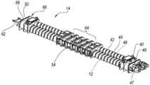
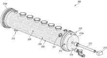
도 5는 도 2의 어셈블리로부터 분리되어 도시된 슬러지 건조기 어셈블리(14)의 등각투상도이다. 슬러지 보유 및 운반 시스템(30)(도 3)으로부터 수송된 습식 슬러지는 슬러지 건조기 어셈블리(14)의 슬러지 입구(40) 속에 공급된다. 도 6에서 알 수 있는 바와 같이, 슬러지 인-피드 어셈블리(34)의 컨베이어(38)의 단부에 연결된 슬러지 수송 오거(52)는 습식 슬러지를 건조기, 어셈블리 입구(40) 속에 공급한다. 슬러지 건조기 어셈블리(14) 속으로 슬러지의 흐름은 실질적으로 연속적이다. 도 6은 입구(40)를 포함하는 슬러지 건조기 어셈블리(14)의 단부의 확대된 부분 등각투상도이다. 습식 슬러지를 수용하는 것 이외에, 슬러지 건조기 어셈블리(14)는 또한 발전소(22)의 증기 엔진(26)으로부터 빠져나온 1차 증기를 수용한다(도 1). 약 207 kPa(약 30 psia)로 증기 엔진(26)을 빠져나가는 배기 1차 증기는 하나 이상의 관형 쉘(42) 속으로 흐르며, 관형 쉘의 각각은 관형 슬러지 캐리어(44)를 각각 포함한다. 배출된 1차 증기로부터의 열은 슬러지 캐리어(44) 내의 슬러지를 가열하여, 슬러지로부터 물을 증발시켜(슬러지 증기를 발생시키고), 슬러지를 건조시켜 고체 연료 물질을 제공한다.5 is an isometric view of the illustrated
예시된 실시태양의 슬러지 건조기 어셈블리(14)는 각각 중공형 슬러지 캐리어(44)를 형성하는 작은 직경의 파이프를 수용하는 쉘(42)을 형성하는 두 개의 밀폐된 대형 직경 파이프를 포함한다. 각각의 슬러지 캐리어(44)는 회전 가능한 중공형 오거(46)를 함유하며, 슬러지 캐리어(44)는 입구(40)를 통해 슬러지를 수용하여 슬러지가 중공형 오거(46)를 적어도 부분적으로 둘러싼다. 예시된 실시태양에서, 각 쉘(42)은 증기 엔진(26)(도 1)으로부터 배출된 1차 증기를 수용하는 증기 입구 (48)를 포함하여 고온의 1차 증기는 쉘의 내부 영역과 슬러지 캐리어(44) 주위로 흘러서, 슬러지 캐리어(44) 내의 슬러지를 가열한다. 따라서, 1차 증기는 슬러지로부터 물리적으로 격리되지만 슬러지에 열을 전달할 수 있어서, 슬러지를 비등시키고 동시에 1차 증기를 냉각시킨다. 또한, 슬러지 건조기 어셈블리(14)로 들어가는 1차 증기의 일부는 오거(46)를 통해 슬러지를 가열하기 위해 중공형 오거(46) 내의 내부 영역 속으로 흐른다. 예시된 실시태양에서, 각각의 중공형 오거(46)는 슬러지 캐리어(44) 내에서 오거(46)를 회전시키고 슬러지가 건조됨에 따라 슬러지 캐리어(44)를 통해 축 방향으로 습식 슬러지를 연속적으로 이동시키는 구동 모터 (47)에 연결된다. 한 실시태양에서, 각각의 구동 모터(47)는 독립 가변 주파수 드라이브에 의해 제어되는 전용 5마력, 인버터-듀티(inverter-duty), 3상 전기 모터이다. 다른 실시태양은 다른 구동 모터를 사용할 수 있다.The
두 개의 슬러지 캐리어(44)는 이송 하우징(50)에서 슬러지 통로를 통해 슬러지가 한 방향으로 하나의 슬러지 캐리어(44)를 통해, 축 방향으로 및 다른 방향으로 다른 슬러지 캐리어(44)를 통해 축 방향으로 흐르도록 하는 슬러지 통로를 각각 갖는 이송 하우징(50)에 의해 말단에서 서로 연결된다.The two
도 7은 입구(40)로부터 슬러지 건조기 어셈블리에서 슬러지 흐름의 개략적 인 등각투상도이다. 슬러지가 슬러지 어셈블리(44)를 통해 순환함에 따라, 슬러지 내의 물은 비등된다. 슬러지로부터의 고체 연료 물질이 충분히 건조되면, 슬러지 캐리어(44) 및 상응하는 쉘(42)의 측면에 형성된 하나 이상의 건조된 연료 출구(54)를 통해 슬러지 건조기 어셈블리(14)를 빠져나간다. 건조 연료 출구(54)는 슬러지 캐리어(44) 및 쉘(42) 사이에서 밀봉되어 슬러지 물질이 1차 증기로부터 격리되도록한다. 예시된 실시태양에서, 건조 연료 출구는 다른 형상(즉, 정사각형, 원형, 타원형 등) 및 크기를 가질 수 있지만, 건조 연료 출구(54)는 직사각형 개구이다.7 is a schematic isometric view of the sludge flow from the
작동시, 슬러지 건조기 어셈블리(14) 내의 슬러지 레벨은 추가의 습식 슬러지가 전이 오거(52)에 의해 슬러지 캐리어(44) 속으로 전달됨에 따라 증가한다(도 6). 슬러지 캐리어(44)를 통해 이동하는 슬러지 내의 고체는 전형적으로 건조 연료 출구(54)에 도달할 때 충분히 건조되고, 충분히 건조된 고체 연료 물질은 아래 논의한 대로 건조 연료 출구(54)로부터 건조 연료 호퍼(56) 속으로 흐른다(도 2). 슬러지가 회전식 중공형 오거(46)에 의해 슬러지 캐리어(44)를 통해 이동하고 취성을 유지하는 것을 보장하기 위해, 적절한 양의 건조된 슬러지가 입구(40)에 인접한 건조 시스템의 개시부 내로 재순환될 것이다. 일부 슬러지는 건조 연료 호퍼(56) 속으로 이동하기 전에 여러 번 슬러지 어셈블리를 통해 재순환될 수 있다(도 2).In operation, the level of sludge in the
건조 슬러지의 이러한 재순환은 또한 슬러지가 "점착" 상으로 불리는 상태에 도달하는 것을 방지하며, 여기서 슬러지 수분 함량은 건조 물질 또는 25% 내지 75% 건조 고체의 킬로그램 당 약 0.3523kg H2O이다. 슬러지가 유체와 같은 특성을 나타내는 "습식" 또는 "페이스트" 구역과는 달리, "점착 상"에서 슬러지 및 슬러지 캐리어(44)의 가열된 사이의 접촉은 급격히 감소하여 증발 속도에 부정적 영향을 미친다. 슬러지가 "점착 "상을 지나서 "과립" 상으로 건조될 때, 건조되는 슬러지는 슬러지 캐리어(44)의 가열된 벽과 균일한 접촉을 더욱더 유지하여, 증발 속도가 원래의 값으로 되돌아가게 한다. 감소된 열 전달 효과에 추가하여, "점착" 구역의 물질은 상당한 전단 강도를 나타내며, 슬러지 물질은 회전 오거(46)에 의해 운반되는 것이 아니라 회전 오거(46)에 더 쉽게 부착될 수 있다. 일부 건조 슬러지 물질의 재순환은 슬러지 건조기 어셈블리의 내용물이 항상 "과립" 구역 내에 또는 가까이에 있도록 하여 "점착" 구역을 피하도록 도와준다.This recycling of the dry sludge also prevents the sludge from reaching a state referred to as a "tacky" phase, wherein the sludge moisture content is about 0.3523 kg H 2 O per kilogram of dry matter or 25% to 75% dry solids. Unlike the "wet" or "paste" zone, where the sludge exhibits fluid like properties, the contact between the sludge and the
도 5에 도시된 예시된 실시태양에서, 슬러지 건조기 어셈블리(14)의 동심 관형 디자인은 매우 내구성이 있다. 그러나, 건조 연료 출구(54)는 가압된 관형 쉘 (42)의 측벽을 관통하여 관형 구조를 약화시킬 수 있다. 따라서, 하나 이상의 보강 립(64)은 건조 연료 출구(54) 주위의 쉘(42)에 부착되어 구조적 완전성을 유지하는 것을 도우며 건조기 어셈블리 내의 1차 증기의 열 및 압력하에서 관형 구조가 소성 변형하는 것을 방지한다.In the illustrated embodiment shown in FIG. 5, the concentric tubular design of the
슬러지 캐리어(44)로부터 건조된 고체 연료 물질을 제거하는 것 이외에, 슬러지로부터 방출된 슬러지 증기는 각 슬러지 캐리어(44)의 내부 영역과 연결되는 증기 출구 포트(66)를 통해 슬러지 건조기 어셈블리(14)로부터 제거된다. 슬러지 증기는 증기 출구 포트(66)로부터 도관을 통해 수 처리 시스템(16)으로 흐르고(도 1), 이는 아래에서 보다 상세히 논의한다. 예시된 실시태양에서, 출구 포트가 다른 위치에 위치될 수 있지만, 적어도 하나의 증기 출구 포트(66)가 슬러지 건조기 어셈블리의 각 단부에 제공된다.In addition to removing the dried solid fuel material from the
1차 증기로부터의 열이 슬러지로 전달됨에 따라, 1차 증기는 냉각되어 슬러지 건조기 어셈블리(14)가 응축기로서 작용하며, 1차 증기는 쉘(42) 내에서 1차 액체 수로 응축된다. 응축물은 슬러지로부터 분리되어 유지되고 1차 액체 수를 추출하여 슬러지 건조기 어셈블리(14)로부터 1차 수로(21)를 따라 1차 액체 수를 운반하는 하나 이상의 1차 수 라인(62) 속으로 향하게 하는 응축물 사이펀 튜브(siphon tube) 어셈블리에 의해 쉘(42)로부터 제거된다(도 1). 도 2에 도시된 예시된 실시태양에서, 슬러지 건조기 어셈블리(14)는 쉘(42) 및 슬러지 캐리어(44)가 수평에 대해 약 1도 기울기로 기울어져서 사이펀 튜브 어셈블리에 의한 1차 수의 추출을 용이하게 하도록 설치된다. 그런 후에 추출된 1차 액체 수는 증기로서 슬러지 건조 어셈블리(14)로 다시 복귀하기 전에 보일러(20) 및 증기 엔진(26)에 의한 사용을 위해 1차 수로(21)를 따라 다시 순환된다.As the heat from the primary vapor is transferred to the sludge, the primary vapor cools and the
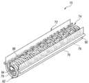
도 8은 슬러지를 혼합하고 건조하기 위해 배출된 1차 증기에 의해 약 100 psig 및 328℉까지 가열된 복수의 회전 및 고정 압력 용기를 포함하는 슬러지 건조기 어셈블리(70)의 다른 실시태양의 부분 등각투시도이다. 예시된 건조기 어셈블리 (70)는 슬러지를 홈통(72)의 한 단부에 있는 출구를 향해 축 방향으로 이동시키는 회전가능한 오거(74)를 함유하는 폐쇄된 밀봉 홈통(72)을 갖는다. 홈통(72)은 한 말단에 있는 입구를 통해 습식 슬러지의 흐름을 수용하여 오거(74)의 적어도 일부가 슬러지 내에 있는다. 홈통(72)은 홈토(72) 내의 구성 요소를 명확하게 도시하기 위해 뚜껑 또는 단부를 도시하지 않고 8에 예시된다. 뚜껑 및 단부는 건조 과정 동안 슬러지 및 배출된 슬러지 증기를 완전히 함유하도록 홈통 본체(76)에 밀봉된다. 한 실시태양에서, 유압 작동 뚜껑은 슬러지 건조기 어셈블리(70)의 내부 구성요소의 전부에 대한 완전하고 용이한 접근뿐만 아니라 홈통(72) 내의 모든 증기, 연무 및 가스를 밀봉하게 한다. 따라서, 슬러지 증기 및 홈통(72) 내의 헤드스페이스로부터의 휘발물질은 정화(즉, 수증기) 및/또는 재연소(즉, 가스 및/또는 휘발물질)를 위해 포획 및 재처리된다.Figure 8 is a partial isometric view of another embodiment of a
도 9는 오거(74)가 분리되어 도시된 증기 가열된 홈통(72)의 확대 등각 투상도이다. 홈통(72)은 증기 엔진(26)(도 1)으로부터 고온으로 배출된 1차 증기를 수용하고 1차 증기를 만곡된 증기 파이프(78)에 균일하게 분배하는 신장된 매니폴드 파이프(80)에 의해 서로 연결된 복수의 고정식, 이격된 곡선형 증기 파이프(78)를 함유한다. 따라서, 슬러지가 입구 근처의 홈통(72)으로 유입되고 오거(74)를 통해 홈통(72)을 따라 이동함에 따라, 슬러지는 곡선형 증기 파이프(78)의 적어도 일부분 위로 이동하여 슬러지를 비등시키고 건조시킨다. 슬러지가 홈통 바디(76)의 단부에 있는 출구에 도달할 때까지, 슬러지는 충분히 건조된다. 또한, 1차 증기는 곡선형 증기 파이프(78) 내에서 응축되고, 응축액은 1차 수로(21)에 연결된 리턴 매니폴드 파이프(82)에 수집된다.9 is an enlarged isometric view of the vapor-
도 10은 홈통(72)으로부터 분리된 상태로 도시된 증기 가열식 가압 오거(74)의 확대 등각투상도이다. 오거(74)는 배출된 1차 증기를 수용하는 중공형 중심 샤프트(84)를 가진다. 또한, 오거(74)는 중심 샤프트(84)의 내부와 연결되고 중심 샤프트(84)로부터 나선형으로 방사상으로 연장하는 복수의 만곡된 증기 파이프(86)를 가진다. 따라서, 만곡된 증기 파이프(86)는 중심 샤프트(84)로부터 1차 증기를 수용한다.10 is an enlarged isometric view of the steam-
오거(74)는 홈통(72) 내에서 회전하도록 구성되어 만곡된 증기 파이프(86)는 홈통(72) 내의 증기 파이프(78) 사이의 공간을 통과한다. 오거의 만곡된 증기 파이프(86)는 중앙 샤프트(78) 위로 홈통을 통해 축 방향으로 슬러지를 결합 및 밀어내는 추진 부재로서 작용하도록 중앙 샤프트(84)에 대해 약간 경사질 수 있어서, 슬러지를 가열하고 비등시킨다. 중앙 샤프트(84) 및 만곡된 증기 파이프(86) 내의 뜨거운 1차 증기는 슬러지를 가열하여, 오거(74) 내에서 1차 증기 응축을 초래한다. 오거의 중심 샤프트(84)의 한 단부는 1차 액체 수로서 응축물을 오거로부터 1차 수로(21)(도 8)를 따라 향하게 하는 응축물 출구를 가진다. 예시된 실시태양에서, 회전하는 오거(74)는 슬러지가 홈통(72)의 한 단부에서 다른 단부로 이동하게 하는 자기 평탄화 효과를 제공하는 혼합 작용을 제공한다. 오거(74)는 또한 건조된 연료 출구로부터 건조된 고체 연료 물질을 계량한다. 적어도 하나의 실시태양에서, 하나 이상의 건조 연료 오거가 건조된 연료 출구에 인접한 홈통(72)에 연결되어 건조된 연료 물질을 건조된 연료 호퍼(56)로 운반할 수 있다.The
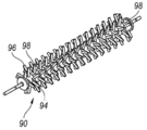
도 11 및 도 12는 도 8과 관련하여 위에서 논의한 홈통 바디(76), 만곡된 증기 파이프(78) 및 슬러지 건조기 어셈블리와 실질적으로 유사한 축 방향 연장 매니폴드 파이프(80)를 구비한 홈통(72) 갖는 슬러지 건조기 어셈블리(70)의 다른 실시태양의 등각투시도이다. 따라서, 만곡된 증기 파이프(78) 및 매니폴드 파이프(80)를 구비한 홈통(72)은 1차 증기에 의해 가열된 고정 압력 용기를 한정한다. 이런 대안적인 실시태양에서, 오거(90)는 홈통(72) 내에 회전 가능하게 위치되고 구동 모터(92)에 의해 구동된다.Figures 11 and 12 illustrate a
오거(90)는 중심 샤프트(94)로부터 반경 방향으로 돌출하는 복수의 중공형 직선 핑거 파이프(96)에 연결된 실질적으로 중공형 중심 샤프트(94)를 가진다. 각각의 핑거 파이프(96)는 오거(90)가 회전하고 스팀 가열 핑거 파이프(96)가 슬러지를 통해 이동하고 건조 슬러지를 건조 연료 출구를 향해 축 방향으로 천천히 이동시킬 때 각각의 핑거 파이프(96)에 추가 강도 및 강성을 제공하도록 중심 샤프트(94)에 고정된 지지 웹(98)을 포함한다. 한 실시태양에서, 지지 웹(98)은 또한 중앙 샤프트의 길이 방향 축에 대해 경사질 수 있으며, 지지 웹(98)은 슬러지의 일부와 결합하여 혼합을 용이하게 하고 및/또는 홈통(72)의 길이를 따라 건조 슬러지를 증가되게 이동시킬 수 있다.The
예를 들어, 오거(90)의 중심 샤프트(94)는 그 길이를 따라 파이프 둘레에 분포된 대략 140개의 돌출하는 5인치 핑거 파이프(96)에 작동 가능하게 연결된 경질의 24-인치 직경 파이프이다. 핑거 파이프(96)는 작업 동안 1차 증기의 응축시 적절한 응축물 제거를 보장하기 위해 증기로 채워진 중심 샤프트(94)의 내부로 연장된다. 각각의 핑거 파이프(96) 및 관련 지지 웹(98)은 그 토크가 핑거 파이프(96) 중 하나의 단부에 완전히 인가되면 구동 모터의 전체 토크의 힘을 수용하면서, 오거의 설계 압력 및 약 100 psig 및 328 ℉과 같은 온도에 대한 물질 허용 응력 아래로 실제 물질 응력을 유지하도록 구성된다. 한 실시태양에서, 핑거 파이프(96)는 구성에서 중심 샤프트(94)의 길이를 따라 대체로 나선형으로 배열된 패턴으로 배향되어 두 개의 핑거 파이프(96)가 정확하게 동일한 순간에 슬러지 물질과 처음에 결합하지 않아서, 오거의 전체 회전을 통해 충격 하중을 고르게 분산시킨다. 또한, 인접한 평면 핑거 파이프 그룹화는 건조 과정 동안 홈통(72)을 통해 슬러지 흐름을 용이하게 하기 위해 약 45°만큼 회전 오프셋된다.For example, the
전술한 바와 같이, 홈통(72) 내에 생성된 슬러지 증기는 증기 출구를 통해 추출된다. 한 실시태양에서, 증기 출구는 건조 공정 중에 슬러지가 향해 이동하는 홈통의 단부 패널에 인접하여 위치된다. 홈통(72)으로부터 제거된 슬러지 증기는 이하에 상세히 논의된 바와 같이, 슬러지 증기가 정화되고 수집되는 수 처리 시스템(16) 속으로 흐른다. As described above, the sludge vapor generated in the
한 실시태양에서 시스템(10)이 매우 습한 슬러지(예를 들어, 약 15% 고체 물질 이하의 고체 함량을 갖는 슬러지)를 처리하는데 사용된다. 시스템(10)은 고압 제1단 건조기 어셈블리(200) 및 저압 제2단 건조기 어셈블리(220)를 포함하는 2단 슬러지 건조기 시스템을 이용하여 습식 슬러지를 건조한다. 도 13a 및도 13b는 본 기술의 한 실시태양에 따라 고압 제1단 건조기 어셈블리(200)의 등각투상도이다. 제1단 건조기 어셈블리(200)는 하나 이상의 타이 로드(tie rods)(205)에 의해 서로 구조적으로 서로 연결된 복수의 이격된, 축 방향으로 정렬된 스크래퍼 디스크(204)를 포함하는 신장된 큰 직경의 외부 파이프(202)를 포함한다. 이 논의의 명확성을 위해, 외부 파이프(202)는 내부 구성 요소를 불명확하게 하는 것을 방지하기 위해 일반적으로 투명하게 도 13a 및 도 13b에 도시된다.In one embodiment,
각각의 스크래퍼 디스크(204)는 다른 스크래퍼 디스크(204) 내의 구멍 (206)과 축 방향으로 정렬되는 복수의 구멍(206)을 가진다. 복수의 증기 튜브(208)는 실질적으로 외부 파이프(202)의 길이를 따라 스크래퍼 디스크 (204) 내의 정렬된 구멍(206) 끝까지 연장된다. 스크래퍼 디스크(204)는 또한 외부 파이프의 내부 표면과 결합하는 베어링(209)을 포함한다. 외부 파이프(202)의 단부는 증기 튜브(208)의 내부와 연결되는 매니폴드 부분(210)에 연결된다. 매니폴드 부분(210) 중 하나(즉, 입구 매니폴드(210a))는 1차 수로와 연결되고 증기 엔진(26)(도 1)으로부터 배출된 고온의 1차 증기를 수용하도록 구성된 증기 입구 포트(212)를 가진다. 1차 증기는 입구 매니폴드(210a)로부터 외부 파이프(202) 내의 증기 튜브 (208) 속으로 흐른다.Each
외부 파이프(202)는 습윤 슬러지가 고온 증기 튜브(208)와 직접 결합하도록 매우 습한 슬러지의 흐름을 파이프의 내부 영역으로 향하게 하는 슬러지 입구 포트(211)를 가진다. 구조적으로 서로 연결된 스크래퍼 디스크(204)는 입구 매니폴트(210a)를 통해 밀봉 가능하게 연장되고 유압 실린더와 같은 액츄에이터(213)에 연결되는 왕복 구동 샤프트(212)에 연결된다. 액츄에이터(213)는 구동 샤프트 (212)를 밀고 당기게 하여, 스크래퍼 디스크(204)를 한 유닛으로 외부 파이프(202) 내에서 습식 슬러지를 통해 축 방향으로 전후 방향으로 이동시킨다. 증기 튜브(208) 내의 고온 1차 증기는 슬러지 내의 물을 비등시켜 슬러지 증기를 발생시켜서, 슬러지의 물 함량을 감소시킨다.The
신장된 오거 어셈블리(214)는 슬러지와 맞물리도록 입구 매니폴드(210a)를 통해 외부 파이프의 내부 영역 속으로 밀봉 가능하게 연장된다. 물 증발 때문에 슬러지가 두꺼워짐에 따라, 오거 어셈블리(214)는 증발된 슬러지를 외부 파이프 (202)를 통해 건조기 어셈블리(200)의 입구 포트(211) 반대쪽의 외부 파이프(202)의 단부에서 있는 슬러지 출구 포트(215)로 이동시키는 것을 돕는다. 추출된 두꺼워진 슬러지는 스로틀(220)을 통과하여 압력을 감소시키고 후술하는 2단 건조기 어셈블리(220)(도 14)로 향하게 된다.The
증기 튜브(208) 내의 1차 증기가 습식 슬러지를 가열 및 비등시킴에 따라, 1차 증기가 응축되고 결과적인 1차 액체 수는 증기 튜브(208)로부터 출구 매니 폴드(210b) 내의 수집 영역으로 흘러나온다. 1차 액체 수는 1차 수 출구 포트를 통해 수집 영역 밖으로 나와 1차 수로(21)의 액체 수를 냉각시키는 라디에이터(190)(이하에서 논의)에 연결된 도관으로 흐른다. 슬러지로부터 배출된 슬러지 증기는 가열되고 건조 공정 동안 고온을 유지하여, 외부 파이프(202)에 있는 동안 슬러지 증기를 살균한다. 도 14에서 알 수 있는 바와 같이, 슬러지 증기는 회수구 포트(216)를 통해 외부 파이프(202)로부터 슬러지 증기를 수 처리 시스템(16)으로 운반하는 슬러지 증기 출구 도관(218) 속으로 배출된다. 그런 후에, 슬러지 증기는 사이클론, 하나 이상의 프리 필터(~25 마이크론 필터) 및 하나 이상의 미세 필터 (~1 마이크론)를 통해 여과된다. 그런 후에 여과된 살균 슬러지 증기는 2단 건조기 어셈블리(220)로 향하게 된다.As the primary vapor in the
예시된 실시태양에서, 2단 건조기 어셈블리(220)는 홈통(72) 내의 만곡된 증기 파이프(78) 및 회전 오거(74 또는 90) 속으로 통과하는 고온 증기가 증기 엔진으로부터의 고온 1차 증기가 아닌 1단 건조기 어셈블리(200)(도 13)로부터의 여과된 살균 슬러지 증기인 것을 제외하고, 도 8-10 또는 도 11-12의 슬러지 건조기 어셈블리와 실질적으로 동일하다. 이 실시태양에서, 1단 건조기 어셈블리(200)로부터의 여과된 살균 슬러지 증기로부터의 열은 2단 건조기 어셈블리(220) 내의 배설물 슬러지를 건조하는데 사용된다. 따라서, 이 2단 슬러지 건조 시스템은 두 배의 슬러지가 실질적으로 동일한 양의 1차 수로 처리되게 한다.In the illustrated embodiment, the two-
가열된 가압 슬러지 증기가 만곡 파이프(78) 및/또는 오거(74/90)를 통해 흐른 후에, 슬러지 증기가 응축된다. 리턴 매니폴드 파이프(82) 및 오거의 중공형 중심 샤프트(84)로부터 추출된 최종 응축물은 수 처리 시스템(16)으로 흐른다. 또한, 2단 건조기 어셈블리(220) 내의 건조 과정은 건조된 배설물 슬러지로부터 물을 비등시키고, 슬러지 증기는 건조기 어셈블리(70)의 홈통(72)을 빠져나와 수 처리 시스템(16)으로 흐른다(도 15).After the heated pressurized sludge vapor flows through the
수 처리 시스템Water treatment system
도 15는 수 처리 시스템(16)의 개략적인 흐름도이다. 슬러지 증기는 슬러지 증기 내에 있을 수 있는 다른 미립자로부터 수증기를 분리하는 사이클론을 포함하는 증기 여과 시스템(100) 속으로 흐른다. 남아있는 가스 및 임의의 미립자(예를 들어, 휘발성 물질 또는 휘발성 유기 화합물(VOC) 등)은 연소기(18)로 다시 운반되어 재연소될 수 있어서, VOC는 대기로 방출되지 않고 파괴되어 슬러지 처리 동안 대기 속으로 악취의 배출을 상당히 감소시키거나 제거한다. 그런 후에 분리된 슬러지 증기는 큰 기공 필터(즉, 25 마이크론 필터)와 같은 하나 이상의 프리 필터를 통과한 후 미세 증기 필터(즉, 1 마이크론 필터)를 통과한다. 그런 다음, 여과된 슬러지 증기는 슬러지 증기를 응축시키고 생성된 살균 액체 수를 수집하는 응축기 (104)로 흐른다. 그런 후에 여과된 슬러지 증기 및 생성된 응축수는 약간의 불순물을 포함할 수 있지만, 슬러지 증기는 슬러지 증기 내의 임의의 병원체를 죽일 수 있을 정도로 충분히 고온에 노출되기 때문에 여과된 증기 및 응축된 액체 수는 병원균이 없다.15 is a schematic flow diagram of a
그런 후에, 살균수는 폭기 공정, 표백 공정, 및 하나 이상의 숯 필터와 같은 선택된 정화 필터를 통한 여과 공정에 의해 정제된다. 그런 후에 정제된 깨끗한 음료수는 정수 저장 탱크(108)에 수집되며, 이로부터 정수가 분배될 수 있다.The sterilized water is then purified by an aeration process, a bleaching process, and a filtration process through a selected purge filter, such as one or more char filters. The purified purified water is then collected in a purified
도 16은 2단 건조기 어셈블리를 사용하는 한 실시태양과 관련된 수 처리 시스템(16)의 개략적인 흐름도이다. 이 실시태양에서, 1단 건조기 어셈블리(200)로부터의 고압 슬러지 증기는 위에서 논의한 바와 같이 수 처리 시스템(16)을 통해 흐르고 여과되어 2단 건조기 어셈블리(220)에서 사용된다. 2단 건조기 어셈블리(220) 내의 슬러지 증기로부터의 응축물은 수집되어 수 처리 시스템(16)을 통과하며 수 처리 시스템에서 응축물은 위에서 논의한 바와 같이 폭기, 표백 및 여과 공정을 통해 정제된다. 수 처리 시스템(16)으로 들어가는 2단 건조기 어셈블리(220)로부터의 슬러지 증기는 또한 여과되고(즉, 사이클론, 프리 필터 및 미세 필터로), 응축되고, 생성된 응축물은 정화되어 저장 탱크(108)에 수집된다.16 is a schematic flow diagram of a
건조 고체 연료 처리 시스템Dry solid fuel processing system
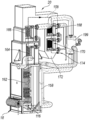
건조 고체 연료 물질로 돌아와서, 위에서 논의한 바와 같이, 건조 고체 연료 물질이 슬러지 건조기 어셈블리 14/70/200/220을 빠져나감에 따라, 건조 고체 연료 물질은 건조 연료 호퍼(56)로 들어간다. 도 17은 보강 립(64)에 인접한 슬러지 건조기 어셈블리(14)에 부착된 건조 연료 호퍼(56)의 등각투상도이다. 도 18은 슬러지 건조기 어셈블리로부터 분리된 건조 연료 호퍼(56)의 확대된 부분 투명 등각투상도이다. 예시된 실시태양의 건조 연료 호퍼(56)는 건조된 고체 연료 물질을 개방된 상부 측면을 통해 수용하는 저장소를 포함한다. 가열 코일(110)은 저장소의 측면에 부착되어 저장소를 가열하여 임의의 공급원으로부터의 액체 수의 응축이 건조된 고체 연료 물질에 도달하지 않도록 한다. 가열 코일(110)로부터의 열은 또한 고체 연료 물질을 더 구동시킬 수 있다. 한 실시태양에서, 연료 저장소 가열 코일(110)은 슬러지 건조기 어셈블리(14)(도 17)에 의해 생성된 슬러지 증기의 일부를 수용하는 증기 코일일 수 있어서, 저장소의 내용물은 약 120℃(240℉) 이상으로 예열된다.Returning to the dry solid fuel material, the dry solid fuel material enters the
물 또는 습기가 여하튼 호퍼(56)로 들어가서 건조된 고체 연료 물질을 적시거나, 또는 건조된 연료 고체 물질이 너무 습기가 있어서 효율적으로 연소하기 힘든 경우, 호퍼(56)는 비워져야 할 것이다. 따라서, 호퍼(56)는 습식 연료를 습식 슬러지 유지 탱크(32)로 되돌리는 습식 연료 아웃-피드(out-feed) 오거(115)를 포함한다(도 1).If the water or moisture somehow enters the
도 18 및 도 19에서 볼 수 있듯이, 예시된 실시태양의 호퍼(56)는 호퍼의 저장소의 바닥에 연결된 건조 연료 컨베이어(112)를 포함한다. 컨베이어(112)는 건조 고체 연료 물질을 연소기(18)의 화실 또는 유동층(116)으로 운반하는 연료 인-피드 오거 어셈블리(114)에 연결되고(도 19), 건조된 고체 연료 물질은 모래 현탁액 입자에서 연소된다. 예시된 실시태양에서, 인-피드 오거(114)는 건조된 고체 연료 물질을 유동층 (116) 약 12cm(4.5 인치) 위 및 이하에서 상세하게 논의된 바와 같이, 연소 팬으로부터 수용된 연소 공기의 흐름과 대략 동일한 높이로 유동층 연소기(18) 속에 공급한다. 예시된 실시태양이 건조 연료 공급 오거 어셈블리(114)를 이용하는 반면, 고체 연료 재료를 연소기에 제공하기 위한 중력 공급 시스템 또는 다른 통증 시스템을 포함하는 다른 연료 전달 시스템이 사용될 필요가 있다.18 and 19, the
한 실시태양에서, 쓰레기 처리 시스템(10)(도 1)은 석탄, 목재 펠릿, 유기 쓰레기 또는 필요한 경우 건조 고체 연료 물질과 함께 유동층 연소기(18)에서 연소될 수 있는 다른 적절한 건조 연료와 같은 보조 연료를 함유하는 보조 건조 연료 호퍼(118)(도 1)를 포함할 수 있다. 보조 건조 연료 호퍼(118)는 또한 연소를 위해 유동층(116)으로 보조 연료를 전달하기 위해 연소기(18)에 연결된 인-피드 오거(120)(도 19)를 포함한다. 인-피드 오거(120)는 또한 연소기(18)의 유동층(116)에 모래, 석회석 또는 다른 선택된 층 물질을 첨가하는데 사용될 수 있다.In one embodiment, the waste treatment system 10 (FIG. 1) includes an auxiliary fuel such as coal, wood pellets, organic waste, or other suitable dry fuel that may be combusted in the
연소기 어셈블리Combustor assembly
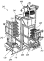
도 19에 도시된 바와 같이, 유동층 연소기(18)는 보일러(20)의 하부에 연결되어 건조된 고체 연료 물질을 연소시키고 보일러(20)를 가열한다. 예시된 실시태양의 연소기(18)는 유동층(116) 및 관련 열 전달 장치를 수용하는 화실(122)을 가진다. 도 20은 배출 오거(128)에 의해 회분 배출 저장소(126)에 연결된 화실(122)의 부분 절결 등각투시도이다. 도 22는 화실(122)로부터 분리되어 도시된 공기 분배 화격자(130)의 확대 등각투시도이다. 예시된 공기 분배 화격자(130)는 균질하고 안정한 방식으로 층(116)을 유동화하도록 구성되며, 연소기 어셈블리(18) 내의 연소 공정을 위한 1차 연소 공기를 공급한다. 석회석 또는 다른 적절한 물질, 또는 이들의 혼합물이 사용될 수 있지만, 예시된 유동층(116)은 모래를 포함한다. 공기 분배 화격자(130)는 뒤틀림, 제동 또는 막힘없이 장시간 동안 작동하도록 구성된다. 공기 분배 화격자(130)는 또한 연소기(18) 및 관련 시스템(10)의 임의의 정지 시간을 최소화하도록 쉽고 신속하게 대체되거나 수리될 수 있도록 하는 방식으로 화실(122)에 통합된다.19, the
공기 분배 화격자(130)는 공기 입구(142) 및 공기 입구(142)의 공기 분배 파이프(140) 하류에 연결된 복수의 스파저형 공기 매니폴드 튜브(144)를 구비한 절연된 공기 분배 파이프(140)를 포함한다. 매니폴드 튜브(144)는 평행하게 서로 매우 가깝게 이격되어 회분 및 작은 모래 입자가 배출 오거(128)에 의한 배출 저장소(126)로의 제거를 위해 매니폴드 튜브(144) 사이에 용이하게 떨어지게 한다(도 20). 그러나, 이격된 매니폴드 튜브(144)는 석회덩어리 및 대형 미 연소 물질이 배출 오거 입구로 떨어지는 것을 방지한다. 각각의 매니폴드 튜브(144)는 격자 형태로 분포된 복수의 버블 캡 공기 노즐(146)에 연결된다. 버블 캡 공기 노즐(146)은 화실 내의 균일한 유동화를 위해 층(116) 위의 프리보드(freeboard) 부분 속으로 매끄럽고 균일한 공기 분배를 제공한다.The
도 21에 도시된 예시된 실시태양에서, 공기 분배 화격자(130)는 유동층(116)의 초기 출발 및 웜업 동안과 같이 필요에 따라 유입 연소/유동화 공기를 예열하도록 활성화될 수 있는 인라인 버너 어셈블리(138)에 연결된다(도 20). 인라인 버너 어셈블리(138)는 연소 팬(148)으로부터 공기 흐름을 수용하는 덮개식 히터(150)를 포함한다. 히터(150)는 공기 분배 파이프(140)(도 22)의 공기 입구(142)에 연결되어 공기 분배 화격자(130)(도 20)를 통해 유동층(116)에 연소 공기를 제공한다. 예시된 실시태양의 연소 팬(148)은 약 50인치 H2O로 압축된 750 ft3/min까지의 대체로 정확한 유속에서 공기를 제공한다. 히터(150)는 필요 시 연소 공기를 예열하기 위해 천연 가스, 프로페인, 부테인 또는 다른 적절한 연료로 작동시킬 수 있다. 일단 연소기(18)가 작동 온도에 가깝게 웜업되면, 인-라인 버너 어셈블리(138)는 더 이상 필요치 않으며, 연소 팬(148)은 고체 연료 물질에 의한 연소를 위해 유동층 (116)에 비가열 공기를 제공한다.21, the
보일러Boiler
연소기 어셈블리(18)는 보일러(20) 내에 위치되고, 건조된 고체 연료 물질을 연소시킬 때 발생된 열은 배출 가스 경로(158)(도 23)를 따라 보일러(20)를 통해 흐르고 증기 엔진(26)(도 1)에 동력을 공급할 고압 증기를 생성하기 위해 1차 수로(160)(도 24)를 따라 보일러(20)를 통해 일반적으로 반대 방향으로 흐르는 1차 액체 수의 연속적인 흐름을 비등시킨다. 보일러(20) 및 이의 구성요소는 배기 가스 경로(158)(도 23)와 관련하여 논의될 것이고, 그런 후에 1차 수로(160)와 관련하여 논의될 것이다.The
도 23은 보일러를 통과하는 가열된 배기 가스 경로(158)를 도시하는 건조 연료 연소기(18) 및 보일러(20)의 확대된, 부분적으로 절결된 등각투상도이다. 보일러(20)의 하부는 유동층(116)의 적어도 일부에 매립되어 그 바로 위에 위치된 증발기(162)를 포함한다. 따라서, 유동층(116)에서 고체 연료 물질을 연소시킴으로써 발생된 고온의 열은 증발기(162) 둘레로 흘러서 효과적으로 가열한다. 배기 가스 경로(158)는 증발기(162)에 연결된 1차 과열기(164)를 통해 증발기(162)로부터 위쪽으로 흐른 다음 1차 과열기(164)에 연결된 2차 과열기(166) 위로 흐른다. 배기 가스 경로(158)는 2차 과열기(166)로부터 1차 절약기(168) 위로 흐른 다음 2차 절약기(170) 위로 흐른다. 배기 가스 경로(158)를 따라 흐르는 가열된 배기 가스는 열을 증발기(162), 1차 과열기(164), 2차 과열기(166), 1차 절약기(168), 및 2차 절약기(170)의 각각에 순차적으로 전달함으로써 냉각된다. 2차 절약기(170)는 절약기 하우징(172)에 포함되고 배출구(174)에 연결된다. 배기 가스가 2차 절약기(170)에 도달하여 위로 흐를 때까지, 배기 가스는 배기구(174)를 빠져나가기 전에 2차 절약기(170)에 저 등급 열만을 전달한다.23 is an enlarged, partially cut away isometric view of the
도 24는 절약기 하우징(172) 및 배기구(174)에 연결된 다중-클론 어셈블리(176)의 확대 부분 등각투시도이다. 배기 가스는 다중-클론 어셈블리(176)로 들어가고 하나 이상의 종래의 사이클론을 통해 흘러 배기 흐름으로부터의 임의의 잔류 회분 또는 미립자를 제거하여, 다중-클론 어셈블리(176)를 빠져나가는 깨끗한 배기 가스를 제공한다. 배기 가스는 화학적으로 처리된 수 칼럼을 통해 거품을 일으켜서 대기로 방출되기 전에 추가의 오염물을 제거할 수 있다. 실질적으로 미립자가 없는 배기 가스는 다중-클론 어셈블리(176)를 빠져나가고 대기로 개방된 배기 스택(178)을 통해 흐른다. 예시된 실시태양에서, 유도 통풍기 팬(180)은 다중-클론 어셈블리(176)와 배기 스택(178) 사이에 위치되고 전체 배기 가스 경로(158)를 따라 배기 스택(178) 외부로 배기 가스의 흐름을 용이하게 하도록 구성된다. 다른 실시태양은 배기 가스 경로(158)를 따라 배기 가스의 유량 및 속도를 제어하기 위해 다른 팬 또는 배기 연신 시스템을 사용할 수 있지만, 예시된 실시태양에서, 팬(180)은 대략 775 scfm의 유속으로 약 8인치의 H2O 진공 상태로 만들 수 있다. 24 is an enlarged partial isometric view of the
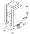
도 25는 하우징의 바닥에 회분 수집 영역(182) 및 회분 수집 영역(182)에 연결된 회분 오거(184)를 갖는 절약기 하우징(172)의 확대 부분 등각투상도이다. 배기 가스가 절약기 하우징(172)에 들어갈 때까지, 배기 가스는 실질적으로 냉각되고, 배기 가스와 함께 흐를 수 있는 임의의 보다 무거운 회분 입자는 회분 수집 영역(182) 속으로 떨어지고 수집 영역(182)에 수집될 것이다. 회분 오거(184)는 절약기 하우징(172)으로부터 수집된 회분을 수집 저장소 또는 다른 수집 시스템(도시되지 않음) 속으로 운반하도록 구성된다. 25 is an enlarged partial isometric view of an
보일러 이전 1차 수로Primary waterway before boiler
이제 1차 수로(160)로 돌아가서, 1차 수의 흐름이 보일러(20)로 액체 상으로 들어간다. 슬러지 건조기 어셈블리(14)와 관련하여 위에서 논의한 바와 같이, 증기 엔진(26)으로부터의 1차 수 흐름은 슬러지 건조기 어셈블리에서 액체 상으로 응축된다. 도 1에 도시된 예시된 실시태양에서, 슬러지 건조기 어셈블리(14)로부터의 1차 액체 수의 흐름은 1차 수로(21)를 따라 계속하기 전에 1차 액체 수를 냉각시키는 것을 돕기 위해 라디에이터(190)를 통과할 수 있다.Returning now to the
1차 수(때로는 "급수"로 불림)가 증기/안개 및 액체 상으로 1차 수로(21)를 통해 이동함에 따라, 1차 수의 일부가 손실될 수 있다. 예를 들어, 일부 1차 수는 증기가 엔진의 실린더 벽을 따라 피스톤을 지나면서 송풍되는 증기 엔진(26)에서의 증기 송풍에 의해 손실될 수 있다. 또한, 1차 수의 일부는 시스템(10)으로부터 제거되어 시스템(10)의 최저 지점에서 폐기되어, 블로우다운(blowdown)이라 불리는 1차 수로부터 침전될 수 있는 임의의 사용된 화학물질 또는 미네랄을 제거할 수 있다. 수질 및 시스템(10)에 따라, 블로우다운은 1차 수의 총 유량의 약 5%까지 구성될 수 있다. 따라서, 보충 수는 라디에이터(190)로부터 하류에 위치된 정수기(192)를 통해 1차 수로(21)에 첨가될 수 있다.As part of the primary water (sometimes called "water") travels through the
또한, 정수기(192)는 화학물질 또는 첨가제를 액체 상인 1차 수에 첨가할 수 있다. 일부 실시태양에서, 화학물질 및/또는 첨가제는 1차 수로(21) 속에 주입된 보충 수에 첨가된다. 예를 들어, 보충 수는 1차 수로에 들어가기 전에 화학 첨가제를 통해 연화되어 보일러(20)의 파이프의 스케일링(scaling)을 감소시킬 수 있다. 화학 첨가제는 불순물 및 부식 생성물을 최소화하기 위해 사용될 수 있는데, 이는 가열 효율에 부정적인 영향을 미치거나 1차 수가 1차 수로(21)에서 통과하여 흐르는 도관의 작동 수명을 잠재적으로 단축시킬 수 있다. 또한, 정수기(192)는 보충 수가 1차 수로(21)에 추가되기 전에 경질 공용수일 수 있는 유입수를 처리하는데 사용될 수 있다.In addition, the
1차 수는 정수기(192)로부터 흘러나와 1차 액체 수가 보일러(20)로 주입되기 전에 급수 탱크(194)에 수집된다. 급수 탱크(194)는 레벨 스위치를 포함하여 1차 액체 수가 복귀된 후, 시스템은 1차 수로(21)에서의 손실을 설명하기 위해 적절한 양의 보충 수와 화학 물질을 측정하고 추가하는 방법을 갖는다. 1차 액체 수는 1차 액체 수를 보일러(20) 속으로 내보내는 급수 펌프(196)에 의해 급수 탱크(194)로부터 당겨진다. The primary water flows out of the
보일러에서 1차 수로Primary channel in boiler
이제 보일러(20)로 돌아가서, 도 26은 보일러(20)를 통과하는 1차 수로(160)를 도시하는 확대된 부분 절결 등각투시도이다. 급수 펌프(196)(도 1)로부터 수용된 1차 액체 수는 2차 절약기(170)에 인접한 수 입구(198)를 통해 보일러(20) 속에 찬 가압수를 공급한다. 펌프(196)로부터의 차가운 1차 수는 약 4130 kPa(600 psia)로 가압되고, 보일러(20) 내의 배기 가스 경로(158)(도 23)의 가장 차가운 부분에서 배기 가스에 의해 가열된 2차 절약기(170)를 통해 흐른다. 예시된 실시태양에서, 2차 절약기(170)는 1차 액체 수를 4.135 MPa에서 약 525 K인 포화점까지 가열한다.Turning now to the
1차 수는 2차 절약기(170)로부터 1차 절약기(168)를 통해 흐르고, 1차 수는 끓는점까지 가열된다. 1차 수는 증기로서 1차 절약기(168)로부터 증기 드럼(199) 속으로 흐르며, 건조된 포화 증기는 임의의 포화 액체로부터 분리된다. 증기 드럼(199) 내의 임의의 포화 액체는 회수되어 증발기(162)로 재주입된다. 건조된 1차 증기는 증기 드럼(199)으로부터 2차 및 1차 과열기(166 및 164)를 통해 순차적으로 흐른다. 1차 증기는 1차 수로(160)의 하류 부분을 따라 보일러(20)로부터 증기 엔진(26)으로 흐르는 고온 과열 증기로서 1차 과열기(164)를 빠져나온다.The primary water flows from the
도 23 및 도 26에 예시된 보일러(20)가 두 개의 과열기(164/166) 및 두 개의 절약기(168/170)를 포함하지만, 다른 실시태양의 보일러(20)는 단지 하나의 과열기 및/또는 단지 하나의 절약기를 포함할 수 있다. 예를 들어, 도 27은 증발기(228) 및 증기 드럼(199)에 연결된 단지 하나의 과열기(224) 및 하나의 절약기(226)를 포함하는 대안적인 실시태양의 보일러 어셈블리(222)의 배관 구성요소의 부분 절결 등각투시도이다. 이 대안적인 실시태양에서, 증기 드럼(199)은 증발기, 유동층(116), 및 화실(122)을 보호하는 것을 돕는 증발기(228)의 대향 측면 상의 수 벽(232)을 형성하는 복수의 수직 파이프에 연결되어 수벽 사이의 열을 보유하고, 수벽(232)을 통해 흐르는 포화 수를 가열하는 것을 돕는다. 따라서, 수벽(232)의 사용은 보일러 내에서 필요한 내화물의 양을 제거하거나 감소시키는 것을 돕는다.Although the
도 28 및 도 29는 다른 실시태양에 따른 보일러(240)의 등각투상도이다. 보일러(240)는 도 27과 유사한 구성요소 레이아웃을 가지며, 하나의 과열기(224) 및 하나의 절약기(226)가 증발기(228)와 나란히 위치되어, 유동층(116) 위의 증발기 섹션 내에서 현저히 많은 프리보드를 허용한다. 이 실시태양은 또한 증기 드럼(199)으로부터 연장되는 수벽(232)을 포함한다. 또한, 보일러(240)는 하우징 (241)을 갖고, 과열기(224), 절약기(226) 및 증발기(228)는 하우징(241)에 연결된 하나 이상의 레일 또는 활동부(244) 상에서 이동 가능하게 운반된 프레임 구조체 (242) 상에 각각 장착된다.28 and 29 are isometric views of a
각각의 프레임 구조(242) 및 이의 각각의 보일러 구성요소(즉, 과열기(224), 절약기(226) 및/또는 증발기(228))는 개방된 노출 위치(도 28) 및 폐쇄된 작동 위치(도 29) 사이의 서랍 운동(drawer motion)과 유사한 이동 가능한 방식으로 하우징(241)에 대해 한 유닛으로서 이동 가능하다. 과열기(224), 절약기(226) 및/또는 증발기(228)의 하나 또는 전부는 시스템(10)(도 1)이 작동하지 않을 때 유지 보수 또는 교체를 위해 모듈 방식으로 개방된 노출 위치로 이동될 수 있다. 보일러 구성 요소가 개방된 노출 위치로 이동되기 전에, 1차 수로(160)를 한정하는 상호연결 파이프 중 일부가 분리될 필요가 있다. 과열기(224), 절약기(226) 및/또는 증발기 (228)는 하우징(241) 속으로 밀폐된 작동 위치까지 다시 미끄러질 수 있고, 상호연결 파이프가 재연결된다. 이러한 모듈 방식은 보일러(240)의 정기적인 유지보수에 대한 비용뿐만 아니라 시스템(10)의 잠재적 다운 타임을 크게 감소시킬 수 있다.Each
다른 실시태양에서, 보일러(20)는 중앙 연소 챔버 및 유동층을 갖는 동심원 보일러일 수 있다. 일반적으로 원통형 증발기는 연소실과 동축으로 배치되고, 과열기 및 절약기는 증발기의 반경 방향 외측에 동심원적으로 배치된다. 다른 실시태양은 다른 구성 및/또는 구성요소 및/또는 구성요소 장치를 구비한 보일러를 이용할 수 있다.In another embodiment, the
발전소power plant
도 30은 증기 엔진(26)에 의해 구동되는 발전기(28)를 구비한 발전소 어셈블리(22)의 등각투상도이다. 예시된 실시태양에서, 발전기(28)는 약 150kW(200hp)까지의 작동 출력을 갖는 175kW 유도 발전기이다. 발전기(28)로부터 생산된 전기는 공기 송풍기, 모든 펌프, 오거를 돌리는 모터 등을 포함하는 모든 기생 부하에 전력을 공급하는데 이용된다. 초과 전력은 국부적으로 사용 가능하게 되거나 선택된 전력 그리드에 제공될 수 있다.30 is an isometric view of a
발전기(28)를 구동시키는 증기 엔진(26)은 보일러(20)(도 1)로부터 과열된 1차 증기를 수용하고, 1차 증기는 약 207kPa(~30psia)로 엔진에서 팽창된다. 증기 엔진은 약 480℃(900℉)까지의 온도에서 고온 증기를 사용하고 약 4130 KPa(600 psia)의 고압에서 장시간 동안 작동하도록 구성된 헤드 어셈블리(300)를 구비한 다중 실린더 왕복운동 피스톤 엔진이다. 예시된 실시태양에서, 엔진(26)은 V-8 왕복운동 피스톤 엔진과 같은 다른 엔진이 사용될 수 있지만, 6기통 엔진이다.The
도 31은 블록으로부터 분리된 엔진 헤드(301)의 부분 절개된 확대 상부 등각투상도이다. 예시된 헤드 어셈블리(300)는 강으로 제조된 헤드(301)를 포함하고 각 실린더를 위한 증기 입구 포트(302)를 포함한다. 증기 입구 포트는 일반적으로 실린더 헤드의 상단에 위치된다. 헤드 어셈블리(300)는 포펫 밸브(306)를 구비한 밸브 트레인 (304) 및 각각의 실린더를 위한 관련 로커 암(308)을 포함한다. 캠 샤프트(310)는 흡기 및 배기 포펫 밸브(306a 및 306b)의 각각을 위한 복수의 정확하게 윤곽을 나타낸 캠(312)을 갖는다. 캠 샤프트(310) 및 관련 캠(312)의 회전은 증기 엔진(26)의 특정 작동 파라미터에 대한 흡기 및 배기 밸브(306a 및 306b)의 개폐를 제어한다.31 is a partially cut enlarged upper isometric view of the
증기 엔진(26)의 왕복 증기 사이클은 이의 실린더 내에서 엔진의 피스톤의 2 행정(stroke)에 걸쳐 일어나는 네 개의 별개의 이벤트로 구성된다. 상사점(TDC)에서 시작하여, 실린더의 흡기 밸브(306a)가 개방되고, 과열된 고압 증기(보일러로부터 수용됨)는 증기 입구 포트(302)를 통해 실린더 속으로 흐르는 반면 피스톤은 하사점(BDC)을 향해 아래로 이동한다. 증기의 특정 컷-오프 체적에서, 흡기 밸브(306a)가 폐쇄되고 피스톤은 BDC까지 동력 행정을 완료한다. BDC에서, 배기 밸브(306b)가 개방되고, 피스톤이 TDC를 향해 상향 이동함에 따라 배기 행정이 시작된다. TDC 전의 특정 시간에, 배기 밸브(306b)가 폐쇄되어 실린더 압력이 보일러 압력에 근접하게 상승한다. 이는 흡기 밸브(306a)가 개방될 때 스로틀링 손실을 최소화한다.The reciprocating steam cycle of the
예시된 실시태양의 증기 엔진(26)이 약 4130 kPa(600 psia)의 보일러 압력에 기초한 증기로 작동하기 때문에, 주어진 보일러 압력과 엔진 토크 한계에 대해 엔진의 효율과 동력을 최대화하기 위해, 흡기 및 배기 밸브(306a 및 306b)는 정밀한 캠 프로파일 및 밸브 트레인 배열을 통해 조심스럽게 제어되어야 한다. 예시된 실시태양에서, 약 4130 kPa(600 psia)의 보일러 압력에서 각 실린더에 대한 컷 오프 비(즉, 실린더의 전체 체적에 대한 컷 오프 체적의 비)는 약 11%이다. 따라서, 흡기 밸브(306a)는 실린더의 11%를 고압의 1차 증기로 충전하기에 충분히 길게 개방되어야 한다. 증기 엔진(26)(도 30)은 약 9.8의 압축비를 갖는 엔진에 대해 약 70cc의 전형적인 통상적인 간극 체적보다는 오히려 약 17.7cc의 간극 체적을 제공하도록 구성된다. 17.7cc의 이 간극 체적은 28°의 크랭크 축 회전을 제공하여 11%의 원하는 컷오프 비를 성취한다. 캠 샤프트(310)가 크랭크 샤프트의 두 배 빠르게 회전하기 때문에, 캠 샤프트(310) 및 캠(312)은 14°의 회전 내에서 각각의 흡기 밸브(306a)를 개폐해야 한다. 이러한 빠른 운동은 캠 프로파일 및 흡기 밸브(306a) 구성에 의해 제어된다.Because the
도 31 및 도 32는 흡기 캠(312a), 흡기 밸브(306a) 및 관련 로커 암(308a)을 도시하는 헤드 어셈블리(300)의 확대 단면도이다. 예시된 실시태양의 엔진에 대한 컷오프 비가 단지 11%인 것을 감안할 때, 각각의 흡기 캠(312a)에 대한 캠 프로파일은 각각의 로커 암(308a)을 신속하고 정확하게 선회시켜 관련된 흡기 밸브 (306a)를 개폐하도록 구성된 극히 작은 로브(314)를 포함한다. 이러한 작은 로브 형상은 캠 공이(318)가 따라야하는 실질적으로 오목하고 작은 반경의 곡선을 생성하는 캠 프로파일 상의 상당히 가파른 전이 영역(316)을 가져야 한다. 예시된 실시 태양에서, 캠 공이(318)는 각각의 흡기 캠(312a) 위의 로커 암(308a) 내의 한 쌍의 베어링(320)에 의해 회전 가능하게 운반되는 회전하는 캠 공이이다. 로커 암(308a) 내의 회전하는 캠 공이(318) 및 베어링(320)의 이러한 배치는 캠 공이(318)가 엔진 (26)의 작동 동안 관성 부하를 처리하게 한다.31 and 32 are enlarged sectional views of the
도 33에 도시된 바와 같이, 흡기 밸브(306a)가 폐쇄될 때, 이의 밸브 헤드(319)는 헤드(301)의 밸브 시트(321) 및 증기 입구 포트(302)의 상부에 밀봉 가능하게 놓여서 흡기 밸브(306a) 위로 (즉, 밸브 헤드의 상부로) 1차 증기를 전달한다. 밸브 트레인(304)은 이의 각각의 캠(312) 위에 수직으로 위치된 캠 공이(318)와 함께 구성되고 캠 공이(318)는 로커 암의 피봇 핀(322)으로부터 이격되어 있다. 또한, 로커 암(308)의 말단부는 흡기 밸브 샤프트(326)의 상부에 나사식으로 부착된 칼라(324)의 하부 표면 아래에 위치되어 맞물린다. 흡기 캠(312a)이 회전하고 캠 공이(318)가 작은 로브(314)와 맞물릴 때, 로커 암(308)은 피봇 핀(322) 주위에서 위쪽으로 피봇되고, 흡기 밸브(306a)를 위로 상승시켜 밸브 헤드(319)를 밸브 시트(321)로부터 떨어지게 하여, 흡기 밸브(306a)를 잠시 개방한다. 따라서, 흡기 밸브(306a)는 풀 포펫 밸브이다. 캠의 로브(314)가 캠 공이(318)를 통과함에 따라, 흡기 밸브(306a)는 신속하게 폐쇄된다. 흡기 밸브(306a)와는 달리, 배기 밸브(306b)는 이런 신속한 반응하는 작용을 필요로 하지 않으며 푸시 포펫(push pppet) 밸브일 수 있다.33, when the
예시된 실린더 헤드 구성은 고온의 고압 증기가 실린더 헤드의 상부에 있고, 입구 밸브(306a)가 고압 증기와 동일한 면에 있을 필요가 있고, 그렇지 않으면 입구 밸브(306a)는 증기압에 의해 열리는 것이다. 입구 밸브의 위치가 증기 입구 포트(402) 아래의 헤드 상부에 있으므로, 고압 증기는 흡기 밸브(306a)를 폐쇄 상태로 유지시킨다. 예시된 실시태양에서, 흡기 밸브(306a)는 피스톤이 컷오프 체적(~ 11%)을 달성할 때까지 TDC로부터 이동함에 따라 실린더 내로 증기를 유입시키도록 흡기 밸브를 들어올리고 개방시키는 것을 돕는 추가적인 힘을 제공하는 스프링 (328)에 연결된다.The illustrated cylinder head configuration requires that the hot high pressure steam be on top of the cylinder head and the
예시된 실시태양의 증기 엔진(26)의 구성은 또한 작동 동안, 특히 고 RPM (즉, ~1850)에서 매우 긴 시간 주기 동안 엔진의 개선된 온도 제어를 제공한다. 피스톤의 양측에 교대로 인가되고 피스톤의 양측에서 배출되는 증기 압력을 갖는 이중 작용 실린더를 사용하는 종래의 증기 엔진과 달리, 예시된 실시태양의 증기 엔진(26)은 단일 작용 실린더를 갖는다. 특히 낮은 작동 온도(즉, 시동 중에)에서 피스톤 주위로 증기 누출을 피하기 위해, 현재의 엔진(26)은 엔진의 온도를 제어하기 위해 라디에이터 및 히터 모두와 함께 엔진에 내장된 액체 냉각제를 이용한다. 엔진(26)이 시동되고 아직 웜업되지 않을 때, 히터는 엔진의 실린더를 물의 비등 온도보다 양호하게 유지하여 증기가 응축되지 않도록 할 것이다. 고압 증기가 뜨겁기 때문에, 엔진이 작동하면, 온도 제어 시스템은 냉각 모드에 있게 된다. 따라서, 온도 제어 시스템은 엔진 온도를 조심스럽게 제어하여 엔진(26)이 너무 뜨거워져서 오일을 손상시키고 너무 차가워(즉, 약 160℉ 미만)지는 것을 방지하며, 크랭크 케이스 내의 오일 및 블로우-바이(blow-by)를 통해 피스톤을 지나가는 임의의 물은 섞여서 분리가 불가능한 에멀젼을 형성한다.The configuration of the
제어장치Control device
예시된 실시태양의 배설물 슬러지 폐기물 처리 시스템(10)은 또한 정상 작동 중에 작업자로부터의 최소한의 감독만으로 전체 시스템(10)을 제어하도록 상호연결되고 구성된 복수의 자동화되고, 통합된 컴퓨터 제어장치를 포함한다. 장비 및 프로세스의 제어 및 모니터링은 주로 센서에서 입력 정보를 수집하고 밸브 및 모터와 같은 제어 장치에 대한 출력 레벨을 설정하는 중앙 프로그래머블 로직 컨트롤러 (PLC)를 통해 수행된다. 또한 PLC는 시동 중에 사용된 발전기 시스템 및 프로페인 버너에 대한 특수 제어장치의 작동을 제어하도록 구성된다. 또한 PLC는 전체 시스템을 정수/증기, 연소, 연료 처리 및 발전과 같은 관리가능한 서브시스템으로 나누도록 구성된다. 제어 입력정보는 원하는 정도로 서브시스템을 서로 분리하도록 제공된다. 서브시스템은 개별 출력정보에 대한 설정 값을 제공하기 위해 제어 루프로 더 나뉠 수 있다.The waste sludge
정수/증기 서브시스템은 일정한 온도 및 압력에서 증기를 발전소(22)에 제공하고, 충분히 건조한 고체 연료를 생성하기 위해 (증기의 형태로) 열을 슬러지 건조기 어셈블리(14)에 제공하도록 구성된다. 제어 루프는 시스템에 유입되는 보충 수의 양, 증발기로 들어가는 응축수 양, 증기 엔진을 우회하는 증기의 양 및 슬러지 건조 어셈블리에 가해지는 열을 조절하는 데 사용된다. 정수/증기 시스템은 또한 도시 물과 같이 시스템에 유입되는 임의의 외부의 물을 모니터하고 처리하며, 블로우다운 시스템(blowdown system)을 통해 보일러 물의 총 용해 고체 함량을 제어하도록 구성된다.The water / steam subsystem is configured to provide steam to the
연소 서브시스템은 정수/증기 시스템이 정확한 양과 온도의 증기를 생성하도록 충분한 열을 제공하도록 구성된다. 시동 중에 프로페인 버너를 작동시키고 연소실의 공기 압력을 제어하기 위해 유동층을 통과하는 공기 흐름을 조절하는 제어 루프가 제공된다. 이 시스템은 또한 연소 배출 및 배기 가스 처리 및 제거 및 유동층 재료 교체와 같은 유지 보수 작업을 모니터할 것이다.The combustion subsystem is configured to provide sufficient heat for the water / steam system to produce steam of the correct amount and temperature. A control loop is provided that actuates the propane burner during start-up and regulates the air flow through the fluidized bed to control the air pressure in the combustion chamber. The system will also monitor maintenance operations such as combustion exhaust and exhaust gas treatment and removal and fluid bed material replacement.
연료 처리 서브시스템은 정확한 양의 건조 연료를 연소 공정에 제공하고 건조 공정으로부터 생성된 폐수를 처리하도록 구성된다. 제어 루프는 정확한 양의 습식 연료를 제공하고, 슬러지 건조기 어셈블리에서 고체 연료 물질의 체류 시간을 조절하고, 건조된 고체 연료 물질을 연소기로 계량하고, 물 응축 및 처리 공정을 처리하는데 사용된다.The fuel processing subsystem is configured to provide an accurate amount of dry fuel to the combustion process and to treat the wastewater generated from the drying process. The control loop is used to provide the correct amount of wet fuel, to adjust the residence time of the solid fuel material in the sludge dryer assembly, to meter the dried solid fuel material to the combustor, and to treat the water condensation and treatment process.
전력 발생 서브 시스템은 이용 가능할 때 그리드에 전력을 제공하도록 구성된다. 이 서브시스템은 전기 출력을 조절하고 엔진 스로틀의 조정을 통해 엔진 속도와 토크를 조절하는 제어 루프를 가진다. 제어 서브시스템 및 저 레벨 루프는 상위 레벨 제어기에 통합되어 시동 및 종료 순서를 처리하고 비상 및 경보 상황을 적절하게 처리할 수 있다.The power generation subsystem is configured to provide power to the grid when available. The subsystem has a control loop that regulates the electrical output and regulates engine speed and torque through adjustment of the engine throttle. The control subsystem and low-level loop can be integrated into the high-level controller to handle start-up and shutdown sequences and to handle emergency and alarm situations appropriately.
전술한 내용으로부터, 예시의 목적으로 본 발명의 특정 실시태양이 설명되었지만, 본 발명으로부터 벗어남이 없이 다양한 수정이 이루어질 수 있음을 이해할 것이다. 또한, 특정 실시태양 또는 실시예의 내용에서 기술된 본 발명의 양태는 다른 실시태양에서 결합되거나 제거될 수 있다. 본 발명의 특정 실시태양과 관련된 이점은 이들 실시태양의 내용에서 기술되었지만, 다른 실시태양은 또한 이러한 장점을 나타낼 수 있다. 또한, 모든 실시태양이 반드시 본 발명의 범위 내에 속하는 이런 장점을 나타낼 필요는 없다. 따라서, 본 발명은 첨부된 청구 범위를 제외하고는 제한되지 않는다.From the foregoing it will be appreciated that while certain embodiments of the invention have been described for purposes of illustration, various modifications may be made without departing from this invention. In addition, aspects of the invention described in the context of particular embodiments or embodiments may be combined or eliminated in other embodiments. While advantages associated with certain embodiments of the invention have been described in the context of these embodiments, other embodiments may also exhibit these advantages. Also, it is not necessary that all embodiments necessarily represent these advantages which fall within the scope of the present invention. Accordingly, the invention is not limited except as by the appended claims.
Claims (30)
증점된 슬러지를 수용하도록 구성된 제 3 가압 용기 및 제 3 내부 건조 용기에 인접한 제 4 가압 용기를 가지는 2단 연료 건조기 어셈블리, 여기서 제 4 가압 용기는 증기 상의 제 1 슬러지 수를 수용하고 포함하도록 구성되어, 제 1 슬러지 수는 증점된 슬러지로부터 분리되고, 증기 상의 제 1 슬러지 수는 증점된 슬러지를 가열하고 건조시켜 증기 상의 제 2 슬러지 수 및 건조된 고체 연료 물질을 제공하며, 제 1 슬러지 수의 적어도 일부는 액체 상으로 응축된다;
증기 상 또는 액체 상 또는 둘 다의 제 1 및 제 2 슬러지 수를 수용하며, 응축기, 정화기 및 필터를 가지는 수 처리 시스템, 여기서 증기 상의 제 1 또는 제 2 슬러지 수는 응축되고, 액체 상의 제 1 및 제 2 슬러지 수는 정제 및 여과되어 음료수를 제공한다;
보일러에서 증기를 생성시키기 위해 2단 연료 건조기 어셈블리로부터 건조된 고체 연료를 연소하도록 구성된 연소기 어셈블리; 및
보일러로부터의 증기에 의해 동력을 받고 전기를 생성시키도록 구성되며, 고온 배기 증기를 생성하는 증기 동력 발전기 어셈블리
를 포함하는 전기 및 음료수 생성을 위한 다기능 폐기물 처리 시스템.Stage fuel dryer assembly having a first pressurized vessel configured to contain sludge comprising water and a solid body and having a second pressurized vessel adjacent the first pressurized vessel wherein the second subsaturated vessel is separated from the sludge and heated And partially dried to produce a high-temperature exhaust steam that produces a first number of steam-phase sludge and thickened sludge;
A second pressurized vessel configured to receive the thickened sludge and a second pressurized vessel adjacent the third inner dryer vessel, wherein the fourth pressurized vessel is configured to receive and contain a first number of sludge on the vapor phase , The first sludge number is separated from the thickened sludge and the first sludge number on the vaporizes the heated sludge by heating and drying to provide a second sludge number on the vapor and a dried solid fuel material, Some are condensed into the liquid phase;
A water treatment system for receiving first and second sludge numbers of a vapor phase or a liquid phase or both, having a condenser, a purifier and a filter, wherein the first or second sludge water vapor phase is condensed, The second sludge number is purified and filtered to provide a beverage;
A combustor assembly configured to combust dried solid fuel from a two-stage fuel dryer assembly to produce steam in the boiler; And
A steam power generator assembly configured to be powered by steam from the boiler and generate electricity, the steam power generator assembly generating hot exhaust steam
Gt; A < / RTI > multifunctional waste treatment system for the production of electricity and beverages comprising:
제 1 가압 용기는 제 2 가압 용기 내에 함유되는 시스템.The method according to claim 1,
Wherein the first pressure vessel is contained within a second pressure vessel.
제 3 가압 용기는 제 4 가압 용기 내에 함유되는 시스템.The method according to claim 1,
And the third pressure vessel is contained within the fourth pressure vessel.
1단 연료 건조기 어셈블리는 제 1 가압 용기에 회전 가능하게 지지된 증기 가열 오거를 포함하는 시스템.The method according to claim 1,
Wherein the first stage fuel dryer assembly includes a steam heating auger rotatably supported by the first pressure vessel.
1단 건조기 어셈블리는 제 1 압력 용기 내에 위치되고 제 2 압력 용기에 대해 상기 슬러지를 이동시키도록 제 2 압력 용기에 대해 이동 가능한 복수의 스크래퍼 플레이트를 포함하는 시스템.The method according to claim 1,
Wherein the first stage dryer assembly includes a plurality of scraper plates movable within the first pressure vessel and movable relative to the second pressure vessel to move the sludge relative to the second pressure vessel.
증기 동력 발전기 어셈블리는 증기 엔진 및 발전기를 포함하는 시스템.The method according to claim 1,
A steam power generator assembly comprising a steam engine and a generator.
1단 및 2단 연료 건조기 어셈블리, 수 처리 시스템 및 발전기 어셈블리는 프레임 상에 장착되고 프레임과 함께 한 유닛으로 운반 가능한 시스템.The method according to claim 1,
The first and second stage fuel dryer assemblies, the water treatment system and the generator assembly are mounted on the frame and can be carried as a unit with the frame.
제 1 증기 출구에 결합되고 음료수로서 사용하기 위해 습식 배설물 슬러지로부터 방출된 증기를 응축하도록 구성된 담수 응축기 어셈블리;
연료 건조기 어셈블리의 건조 연료 출구에 결합되고, 연소기 부분을 가지며 연소기 부분으로부터 열을 수용하도록 구성된 보일러를 갖는 건조 연료 연소기 어셈블리로서, 상기 보일러는 수 입구 및 제 2 증기 출구를 가진다;
보일러의 제 2 증기 출구에 연결되고 전기를 생성시키도록 구성된 증기 동력 발전기로서, 증기 동력 발전기는 응축기 부분의 증기 입구에 연결된 제 3 증기 출구를 가진다; 및
연료 건조기의 응축기 부분의 유체 출구에 연결된 수 입구를 갖는 수 펌프; 및 보일러의 수 입구에 연결된 수 출구를 갖는 수 펌프;
를 포함하며,
보일러는 보일러로 유입되는 물의 흐름을 증기 동력 발전기에 동력을 공급하는 증기의 흐름으로 전환시키도록 구성되는 전기 및 음료수 생성을 위한 자급식 다기능 배설물 폐기물 처리 시스템.A fuel dryer assembly having a fuel passage with a fuel inlet configured to receive a flow of a wet excrement sludge comprising a mixture of water and a solid fuel material, the fuel dryer assembly boiling the wet excrement sludge, Wherein the fuel dryer has a condenser portion having a first steam outlet, a dry fuel outlet, and a fluid path with an isolated fluid outlet from the steam inlet and the fuel path;
A fresh water condenser assembly coupled to the first steam outlet and configured to condense the vapor discharged from the wet slurry sludge for use as a beverage;
A dry fuel combustor assembly coupled to the dry fuel outlet of the fuel dryer assembly, the dry fuel combustor assembly having a combustor portion and configured to receive heat from the combustor portion, the boiler having a water inlet and a second steam outlet;
A steam power generator connected to the second steam outlet of the boiler and configured to generate electricity, the steam power generator having a third steam outlet connected to the steam inlet of the condenser portion; And
A water pump having a water inlet connected to a fluid outlet of the condenser portion of the fuel dryer; And a water outlet having an outlet connected to a water inlet of the boiler;
/ RTI >
Wherein the boiler is configured to convert the flow of water into the boiler into a stream of steam that powers the steam power generator.
연료 건조기는 연료 캐리어 내의 증기 가열 오거를 포함하고, 건조 공정 동안 배설물 슬러지를 이동시키고 비등시키도록 구성된 시스템.9. The method of claim 8,
The fuel dryer includes a steam heating auger in the fuel carrier and is configured to move and boil the excrement sludge during the drying process.
연료 건조기는 응축기 부분에 각각 연결되고 증기 동력 발전기로부터의 배기 증기로부터의 열을 사용하여 배설물 슬러지로부터 물을 증발시켜 배설물 슬러지를 건조하도록 구성되는 순차적인 제 1 및 제 2 건조기 단을 갖는 2단 건조기인 시스템. 9. The method of claim 8,
The fuel dryer comprises a two-stage dryer having sequential first and second dryer stages, each connected to the condenser section and configured to evaporate water from the excrement sludge using heat from the exhaust steam from the steam power generator to dry the excrement sludge In system.
제 1 건조기 단은 배설물 슬러지로부터 슬러지 증기를 생성하고, 제 2 건조기 단은 제 1 건조기 단으로부터의 슬러지 증기를 사용하여 슬러지를 건조시키는 시스템.11. The method of claim 10,
Wherein the first dryer stage produces sludge vapor from the excreta sludge and the second dryer stage uses the sludge vapor from the first dryer stage to dry the sludge.
제 1 건조기 단은 배설물 슬러지로부터 물 증발에 의한 제 1 건조기 증기를 생성하고, 제 2 건조기 단은 제 1 건조기 단에 결합되고 배설물 슬러지에 인접한 제 1 건조기 증기를 운반하도록 구성된 제 1 증기 캐리어 부분을 가지며, 제 2 건조기 단은 제 1 증기 캐리어 부분으로부터 분리되고 배설물 슬러지에 인접한 증기 동력 발전기로부터 배기 증기를 운반하도록 구성된 제 2 건조기 증기 캐리어 부분을 가지며, 제 1 및 제 2 증기 캐리어 부분으로부터의 열은 그 내부에서 이동하는 배설물 슬러지를 건조시키는 시스템.11. The method of claim 10,
The first dryer stage producing a first dryer vapor by evaporation of water from the slurry sludge and the second dryer stage being coupled to the first dryer stage and having a first vapor carrier portion configured to carry a first dryer vapor adjacent to the slurry sludge And the second dryer stage has a second dryer vapor carrier portion separated from the first steam carrier portion and configured to convey the exhaust steam from the steam power generator adjacent to the fecal sludge and heat from the first and second steam carrier portions A system for drying the excrement sludge moving therein.
연료 건조기 어셈블리는 증기 동력 발전기로부터 배기 증기를 응축기 부분에 수용하도록 구성되며, 연료 건조기는 연료 입구에 연결되고 응축기에 연결되고 배기 증기로부터의 열로 배설물 슬러지로부터의 물의 제 1 부분을 증발시키도록 구성된 제 1 히터 부분을 갖는 제 1 건조기 단, 및 제 1 건조기 단에 연결되고 배기 증기로부터의 열로 제 1 건조기 단으로부터 수용된 증점된 배설물 슬러지로부터의 물의 제 2 부분을 증발시키도록 구성된 제 2 건조기 단을 갖는 시스템.9. The method of claim 8,
The fuel dryer assembly is configured to receive exhaust steam from the steam power generator in the condenser section, the fuel dryer being connected to the fuel inlet and connected to the condenser and configured to evaporate a first portion of the water from the excreta sludge as heat from the exhaust steam A first dryer stage having a first heater section and a second dryer stage connected to the first dryer stage and configured to evaporate a second portion of the water from the thickened excrement sludge received from the first dryer stage into heat from the exhaust steam system.
연료 건조기 어셈블리의 응축기는 제 1 증기 입구를 통해 증기 동력 발전기로부터 배기 증기를 수용하도록 구성되고, 연료 건조기 어셈블리는 연료 입구에 연결되고 응축기 부분에 인접한 1단 건조기 부분을 가지며, 1단 건조기 부분은 응축기에서 배기 증기로부터의 열을 사용하여 배설물 슬러지로부터 물을 증발시키도록 구성되는 시스템.9. The method of claim 8,
The condenser of the fuel dryer assembly is configured to receive exhaust steam from the steam power generator through a first steam inlet, the fuel dryer assembly having a first stage dryer section connected to the fuel inlet and adjacent to the condenser section, Wherein the system is configured to utilize heat from the exhaust steam to evaporate water from the excreta sludge.
연소기 부분은 유동층 연소기 어셈블리인 시스템.9. The method of claim 8,
Wherein the combustor portion is a fluidized bed combustor assembly.
연료 건조기 어셈블리, 담수 응축기, 건조 연료 연소기 어셈블리, 증기 동력 발전기 및 수 펌프는 프레임 상에 장착되고 프레임과 함께 한 유닛으로 운반 가능한 시스템.9. The method of claim 8,
The fuel dryer assembly, the fresh water condenser, the dry fuel combustor assembly, the steam power generator and the water pump are mounted on the frame and can be carried as one unit with the frame.
증기 동력 발전기는 단일 작용, 액체 냉각 증기 엔진인 시스템.9. The method of claim 8,
The steam power generator is a single acting, liquid cooled steam engine.
제 1 증기 출구에 연결되고 음료수로서 사용하기 위해 슬러지로부터 방출된 증기를 응축하도록 구성된 담수 응축기 어셈블리;
슬러지 건조기 어셈블리에 결합되어 그로부터의 건조 연료 물질을 수용하도록 구성된 연소기 어셈블리, 연소기 어셈블리는 건조 연료 물질을 수용하고 연소하도록 구성된 연소기 및 수 입구와 제 2 증기 출구 사이에서 연장되는 유체 경로에 증기를 생성하기 위한 연소기로부터 열을 수용하도록 구성된 보일러; 및
증기 엔진 및 증기 엔진에 의해 구동되는 발전기를 포함하는 발전소, 증기 엔진은 보일러로부터의 증기를 수용하기 위해 상기 보일러의 제 2 증기 출구에 연결되고, 발전기는 전기를 생성시키도록 구성되며, 증기 동력 발전기는 응축기 부분의 증기 입구에 연결된 제 3 증기 출구를 가진다;
를 포함하며,
증기 엔진으로부터 배출된 증기로부터의 열은 슬러지 건조기 내의 슬러지 내의 물을 비등시키고,
증기 엔진으로부터 배출된 증기는 액체 수의 흐름으로 응축되고;
보일러는 액체 수의 흐름을 수용하여 증기의 흐름으로 전환시켜 증기 동력 발전기에 전력을 공급하도록 구성되는 전기 및 음료수 생성을 위한 슬러지 처리 시스템.A sludge dryer assembly having a fuel path with a sludge inlet configured to receive a flow of sludge comprising a mixture of water and a solid fuel material, the sludge dryer assembly heating the sludge and thermally separating water from the solid fuel to produce a dry fuel material The heater portion having a first vapor outlet, the sludge dryer assembly having a portion of the condenser adjacent the heater portion and having a fluid passageway isolated from the fuel passageway and having a vapor inlet and a fluid outlet;
A fresh water condenser assembly coupled to the first steam outlet and configured to condense the vapor discharged from the sludge for use as a beverage;
A combustor assembly coupled to the sludge dryer assembly and configured to receive dry fuel material therefrom, the combustor assembly comprising a combustor configured to receive and combust the dry fuel material and a combustor configured to combust the combustible gas to produce steam in a fluid path extending between the water inlet and the second steam outlet A boiler configured to receive heat from a combustor for the boiler; And
A steam engine including a steam engine and a generator driven by a steam engine, the steam engine being connected to a second steam outlet of the boiler for receiving steam from the boiler, the generator being configured to generate electricity, Has a third steam outlet connected to the steam inlet of the condenser section;
/ RTI >
Heat from the steam exiting the steam engine boils water in the sludge in the sludge dryer,
Vapor discharged from the steam engine condenses into the flow of liquid water;
Wherein the boiler is configured to receive the flow of liquid water and convert it into a stream of steam to supply power to the steam power generator.
슬러지 건조기 어셈블리의 히터 부분은 슬러지가 이동하는 슬러지 캐리어 부분, 슬러지 캐리어에 인접하고 증기 캐리어의 증기로부터 슬러지로 열의 전달을 위해 슬러지에 인접하여 배치된 증기 캐리어, 및 연료 캐리어 내에 이동 가능하게 배치되고 증기 캐리어에 대해 연료 캐리어 내의 슬러지를 이동시키도록 구성된 복수의 추진 부재를 포함하는 시스템.19. The method of claim 18,
The heater portion of the sludge dryer assembly includes a sludge carrier portion through which the sludge moves, a vapor carrier adjacent to the sludge adjacent to the sludge for transferring heat from the vapor of the vapor carrier to the sludge carrier and adjacent to the sludge carrier, And a plurality of pushing members configured to move sludge in the fuel carrier relative to the carrier.
연료 건조기 어셈블리는 응축기 부분에 각각 결합되고, 증기 엔진으로부터의 배기 증기로부터의 열을 사용하여 연료로부터 물을 증발시킴으로써 슬러지를 건조하도록 구성된 순차적인 제 1 및 제 2 건조기 단을 갖는 2단 건조기인 시스템.19. The method of claim 18,
Wherein the fuel dryer assembly is a two-stage dryer having a sequential first and second dryer stages each configured to dry the sludge by being coupled to the condenser portion and using heat from the exhaust steam from the steam engine to evaporate water from the fuel .
연료 건조기 어셈블리는 순차적인 제 1 및 제 2 건조기 단을 갖는 2단 건조기이고, 제 1 건조기 단은 슬러지로부터 슬러지 증기를 생성하고, 제 2 건조기 단은 제 1 건조기 단으로부터의 슬러지 증기를 사용하여 슬러지를 건조시키는 시스템.19. The method of claim 18,
The fuel dryer assembly is a two-stage dryer having sequential first and second dryer stages, wherein the first dryer stage produces sludge vapor from the sludge, and the second dryer stage uses sludge vapor from the first dryer stage, ≪ / RTI >
연료 건조기 어셈블리는 순차적인 제 1 및 제 2 건조기 단을 갖는 2단 건조기이고, 제 1 건조기 단은 슬러지로부터의 물 증발에 의해 제 1 건조기 증기를 생성하고, 제 2 건조기 단은 제 1 건조기 단에 결합되고 슬러지에 인접한 제 1 건조기 증기를 운반하도록 구성된 제 1 증기 캐리어 부분을 가지며, 제 2 건조기 단은 제 1 증기 캐리어 부분으로부터 격리되어 슬러지에 인접한 증기 엔진으로부터 배기 증기를 운반하도록 구성된 제 2 증기 캐리어 부분을 가지며, 제 1 및 제 2 증기 캐리어 부분으로부터의 열은 그 내부에서 이동하는 슬러지를 건조시키는 시스템.19. The method of claim 18,
The fuel dryer assembly is a two-stage dryer having sequential first and second dryer stages, wherein the first dryer stage produces a first dryer vapor by evaporation of water from the sludge, and the second dryer stage is connected to the first dryer stage And a second dryer carrier configured to convey the first dryer vapor adjacent to the sludge, the second dryer stage having a second vapor carrier coupled to the second vapor carrier, the second vapor carrier being configured to carry exhaust steam from a steam engine adjacent to the sludge, Wherein the heat from the first and second vapor carrier portions dries the moving sludge therein.
제 1 건조기 단은 제 1 연료 캐리어, 제 1 연료 캐리어에 인접한 제 1 증기 캐리어, 제 1 연료 캐리어 내에 이동 가능하게 배치되고 슬러지를 제 1 연료 캐리어를 통해 제 1 증기 캐리어를 지나가게 이동시키도록 구성된 복수의 추진 부재를 포함하며; 2단은 제 2 연료 캐리어, 제 2 연료 캐리어 내에 있으며 제 2 연료 캐리어에 대해 고정된 복수의 증기 가열 부재, 및 제 2 연료 캐리어 내에 회전 가능하게 배치되고 슬러지를 제 2 연료 캐리어 내에서 증기 가열 부재를 지나가게 이동시키도록 구성된 제 2 증기 캐리어 어셈블리를 포함하는 시스템.19. The method of claim 18,
The first dryer stage includes a first fuel carrier, a first vapor carrier adjacent to the first fuel carrier, a second vapor carrier disposed movably within the first fuel carrier and configured to move the sludge past the first vapor carrier through the first fuel carrier A plurality of pushing members; A second fuel carrier, a plurality of steam heating members within the second fuel carrier and secured to the second fuel carrier, and a plurality of steam heating members disposed rotatably within the second fuel carrier, And a second vapor carrier assembly configured to move past the first vapor carrier assembly.
슬러지 건조기 어셈블리의 응축기 부분은 증기 엔진으로부터 배기 증기를 수용하도록 배치되고, 슬러지 건조기 어셈블리는 응축기 부분에 결합되고 배기 증기로부터의 열로 슬러지로부터의 물의 제 1 부분을 증발시키도록 구성된 제 1 가열기 부분을 구비한 제 1 건조기 단, 및 제 1 건조기 단에 연결되고 배기 증기로부터의 열로 제 1 건조기 단으로부터 수용된 증점된 습식 연료로부터의 물의 제 2 부분을 증발시키도록 구성된 제 2 건조기 단을 갖는 시스템.19. The method of claim 18,
The condenser portion of the sludge dryer assembly is arranged to receive exhaust steam from the steam engine and the sludge dryer assembly has a first heater portion coupled to the condenser portion and configured to evaporate a first portion of the water from the sludge with heat from the exhaust steam And a second dryer stage connected to the first dryer stage and configured to evaporate a second portion of the water from the thickened wet fuel received from the first dryer stage into heat from the exhaust steam.
응축기 부분은 증기 동력 발전기로부터 배기 증기를 수용하도록 구성되고, 연료 건조기 어셈블리는 응축기 부분에 인접하여 응축기 내의 배출 증기로부터의 열을 사용하여 배설물 슬러지로부터 물을 증발시키도록 구성된 1단 건조기 부분을 갖는 시스템.19. The method of claim 18,
The condenser portion being configured to receive exhaust steam from a steam power generator and the fuel dryer assembly having a first stage dryer portion configured to evaporate water from the excreta sludge using heat from the exhaust steam in the condenser adjacent the condenser portion, .
연소기 부분은 건조 연료 연소를 위한 연소기 층 및 연소 공기를 연소기 층에 제공하도록 구성된 공기 화격자를 갖는 화실을 구비한 유동층 연소기 어셈블리이고, 보일러는 물 입구에 연결되고 이를 통해 흐르는 물을 가열하도록 구성된 제 1 열 교환기, 제 1 열 교환기에 결합되고 증발기로부터의 증기의 흐름을 수용하도록 구성된 증기 드럼, 증기 드럼에 결합되고 이로부터 가열되고 포화된 유체를 수용하도록 구성된 증발기, 증기 드럼에 결합되고 증기 드럼으로부터 건조 증기를 수용하도록 구성된 제 2 열교환기를 포함하며, 제 2 열교환기는 제 2 증기 출구에 연결되는 시스템.19. The method of claim 18,
The combustor portion is a fluidized bed combustor assembly having a combustion chamber having a combustor layer for burning dry fuel and an air grating configured to provide combustion air to the combustor bed, the boiler having a first portion connected to the water inlet and configured to heat the flowing water therethrough, A vapor drum coupled to the first heat exchanger and configured to receive the flow of vapor from the evaporator, an evaporator coupled to the vapor drum and configured to receive the heated and saturated fluid therefrom, a vaporizer coupled to the vapor drum, And a second heat exchanger configured to receive steam, wherein the second heat exchanger is connected to the second steam outlet.
배설물 슬러지 저장 탱크
배설물 슬러지 저장 탱크에 연결되고 배설물 슬러지를 슬러지 건조기 어셈블리의 슬러지 입구에 제공하도록 구성된 슬러지 운반기를 추가로 포함하는 시스템.19. The method of claim 18,
Sewage sludge storage tank
And a sludge carrier connected to the feces sludge storage tank and configured to provide feces sludge to the sludge inlet of the sludge dryer assembly.
증기 엔진 어셈블리로부터 발생된 전기의 적어도 일부를 수용하는 배설물 슬러지 시스템으로서, 배설물 슬러지 시스템은 슬러지 건조기 어셈블리 및 흐르는 배설물 슬러지를 슬러지 건조기 어셈블리로 전달하도록 구성된 슬러지 운반 시스템을 포함하며, 응축기는 슬러지 건조기 어셈블리에 부착되고 배설물 슬러지의 흐름에 제 1 열을 전달하여 배설물 슬러지로부터의 제 1 증기로서 물을 배출하여 배설물 슬러지 내의 고체 연료 물질을 건조시키도록 구성된다;
슬러지 건조기 어셈블리에 연결되고 깨끗한 액체 음료수로서 수집 부분에서 수집하기 위해 제 1 증기를 수용 및 응축하도록 구성된 물 수집 시스템; 및
배설물 슬러지 시스템 및 발전 시스템의 보일러에 연결된 연소기 시스템으로서, 배설물 슬러지 시스템으로부터 건조 고체를 연소시키고 증기 엔진에 증기를 제공하는 보일러 어셈블리 내의 수로에 열을 제공하도록 구성된 연소기를 포함하는 연소기 시스템을 포함하는 전기 및 음료수 생성을 위한 배설물 폐기물 처리 시스템.A steam power generation system comprising a boiler assembly connected to each other, a steam engine and a condenser and having a primary waterway for conveying primary water through a boiler assembly, a steam engine assembly and a condenser, wherein the steam engine assembly do;
A fecal sludge system for receiving at least a portion of electricity generated from a steam engine assembly, the fecal sludge system comprising a sludge drier assembly configured to deliver a sludge dryer assembly and a flowing fecal sludge to a sludge dryer assembly, And configured to deliver a first heat to the flow of excreta sludge to drain water as a first vapor from excreta sludge to dry the solid fuel material in excreta sludge;
A water collection system connected to the sludge dryer assembly and configured to receive and condense the first vapor for collection at the collection section as clean liquid beverage; And
A combustor system connected to a boiler of a feces sludge system and a power generation system, comprising: a combustor system including a combustor configured to provide heat to a channel in a boiler assembly that burns dry solids from a feces sludge system and provides steam to the steam engine And fecal waste treatment system for beverage production.
슬러지 건조 어셈블리는 순차적인 제 1 및 제 2 건조기 단을 갖는 2단 건조기이며, 제 1 건조기 단은 슬러지로부터 슬러지 증기를 생성하고, 제 2 건조기 단은 제 1 건조기 단으로부터의 슬러지 증기를 사용하여 슬러지를 건조시키는 시스템.29. The method of claim 28,
The sludge drying assembly is a two-stage dryer having sequential first and second dryer stages, wherein the first dryer stage produces sludge vapors from the sludge and the second dryer stage uses sludge vapors from the first dryer stage, ≪ / RTI >
슬러지 건조 어셈블리는 순차적인 제 1 및 제 2 건조기 단을 포함하며, 제 1 건조기 단은 슬러지 운반 시스템으로부터 배설물 슬러지의 실질적으로 연속적인 흐름을 수용하고, 부분적으로 건조된 증점된 배설물 슬러지의 실질적으로 연속적인 흐름을 제 2 건조기 단에 제공하며, 제 2 건조기 단은 실질적으로 건조된 고체 연료 물질을 연소기에 제공하고, 제 1 및 제 2 건조기 단으로부터의 증기는 물 수집 시스템에 제공되는 시스템.29. The method of claim 28,
The sludge drying assembly includes sequential first and second dryer stages, wherein the first dryer stage receives a substantially continuous flow of excreta sludge from the sludge delivery system, and substantially continuous of the partially dried thickened excreta sludge Wherein the second dryer stage provides the substantially dry solid fuel material to the combustor and the vapor from the first and second dryer stages is provided to the water collection system.
Applications Claiming Priority (3)
| Application Number | Priority Date | Filing Date | Title |
|---|---|---|---|
| US14/542,521 | 2014-11-14 | ||
| US14/542,521 US9708937B2 (en) | 2014-11-14 | 2014-11-14 | Multi-functional fecal waste and garbage processor and associated methods |
| PCT/US2015/059765 WO2016077241A1 (en) | 2014-11-14 | 2015-11-09 | Multi-functional fecal waste and garbage processor and associated methods |
Publications (2)
| Publication Number | Publication Date |
|---|---|
| KR20170083608A true KR20170083608A (en) | 2017-07-18 |
| KR101947630B1 KR101947630B1 (en) | 2019-05-30 |
Family
ID=55954901
Family Applications (1)
| Application Number | Title | Priority Date | Filing Date |
|---|---|---|---|
| KR1020177016206A KR101947630B1 (en) | 2014-11-14 | 2015-11-09 | Multi-Functional Fecal Waste and Garbage Processor and Associated Methods |
Country Status (24)
| Country | Link |
|---|---|
| US (5) | US9708937B2 (en) |
| EP (2) | EP3218314B1 (en) |
| JP (2) | JP6415744B2 (en) |
| KR (1) | KR101947630B1 (en) |
| CN (2) | CN107406285B (en) |
| AU (3) | AU2015346575C1 (en) |
| BR (1) | BR112017010113B1 (en) |
| CA (2) | CA3111514C (en) |
| ES (2) | ES2938879T3 (en) |
| FI (1) | FI3733615T3 (en) |
| HK (1) | HK1247908A1 (en) |
| HU (2) | HUE061554T2 (en) |
| MX (2) | MX370144B (en) |
| MY (1) | MY188738A (en) |
| NZ (2) | NZ759156A (en) |
| PH (1) | PH12017500848A1 (en) |
| PL (2) | PL3218314T3 (en) |
| PT (2) | PT3733615T (en) |
| RS (2) | RS60313B1 (en) |
| RU (2) | RU2682573C2 (en) |
| SG (2) | SG11201703610RA (en) |
| TW (3) | TWI622433B (en) |
| WO (1) | WO2016077241A1 (en) |
| ZA (2) | ZA201703298B (en) |
Cited By (1)
| Publication number | Priority date | Publication date | Assignee | Title |
|---|---|---|---|---|
| KR102141300B1 (en) * | 2019-02-27 | 2020-08-05 | (주)규원테크 | Cogeneration system using solid fuel |
Families Citing this family (30)
| Publication number | Priority date | Publication date | Assignee | Title |
|---|---|---|---|---|
| US11129911B2 (en) * | 2011-05-05 | 2021-09-28 | Cedars-Sinai Medical Center | Assessment of coronary heart disease with carbon dioxide |
| AU2012284946A1 (en) * | 2011-07-19 | 2014-02-27 | Mitsubishi Hitachi Power Systems, Ltd. | Drying conveyer, and thermal electric power generation system provided with same |
| US10982162B2 (en) | 2011-09-01 | 2021-04-20 | Akbev Group, Llc | High protein organic materials as fuel and processes for making the same |
| US11866669B2 (en) | 2011-09-01 | 2024-01-09 | Akbev Group, Llc | High protein organic materials as fuel and processes for making the same |
| US10781388B2 (en) | 2011-09-01 | 2020-09-22 | Akbev Group, Llc | High protein organic materials as fuel and processes for making the same |
| US11441090B2 (en) | 2011-09-01 | 2022-09-13 | Akbev Group, Llc | High protein organic materials as fuel and processes for making the same |
| US10738249B2 (en) * | 2012-01-30 | 2020-08-11 | Aries Gasification, Llc | Universal feeder for gasification reactors |
| US9708937B2 (en) * | 2014-11-14 | 2017-07-18 | Bill & Melinda Gates Foundation | Multi-functional fecal waste and garbage processor and associated methods |
| CN107512817B (en) * | 2017-10-23 | 2018-11-23 | 泉州市春川贸易有限公司 | Sewage treatment circulating-use equipment in carwash shop |
| CN108218178B (en) * | 2017-12-29 | 2020-12-18 | 嘉兴科禾能源科技有限公司 | Portable livestock-raising farm excrement and urine automatic collection encapsulation equipment |
| NO343915B1 (en) * | 2018-01-16 | 2019-07-08 | Waister As | System and method of drying solid materials and liquid-solid mixtures |
| US10800667B1 (en) | 2018-05-03 | 2020-10-13 | Sedron Technologies, LLC | System and method for multi-functional slurry processing |
| TWI659096B (en) * | 2018-06-05 | 2019-05-11 | 國立成功大學 | Dual fluidized-bed gasification system |
| US20210292208A1 (en) * | 2018-07-27 | 2021-09-23 | Tapas CHATTERJEE | System and method for reducing volume of sewage sludge |
| CN109008835B (en) * | 2018-10-12 | 2020-09-25 | 河北建材职业技术学院 | Multifunctional lathe waste collection device |
| US11141029B1 (en) * | 2018-11-09 | 2021-10-12 | Sedron Technologies, LLC | Waste processing toilet for use in locations having limited utility service |
| CN109336324B (en) * | 2018-11-24 | 2023-09-12 | 无锡诚尔鑫环保装备科技有限公司 | Device for preparing pure water from reverse osmosis concentrated water and working method thereof |
| RU2726666C1 (en) * | 2019-06-06 | 2020-07-15 | Федеральное государственное бюджетное образовательное учреждение высшего образования "Кубанский государственный технологический университет" (ФГБОУ ВО "КубГТУ") | Apparatus for drying pumpkin seeds by convection |
| CN110397481B (en) * | 2019-07-02 | 2022-04-12 | 光大环保技术研究院(南京)有限公司 | Garbage incineration power generation device capable of improving main steam parameters |
| CN110357355A (en) * | 2019-07-17 | 2019-10-22 | 青岛科技大学 | A kind of saliferous Glycerol Wastewater processing system and technique |
| CN110981152A (en) * | 2019-12-13 | 2020-04-10 | 王凯军 | Multi-stage integrated device and method for drying, catalytic pyrolysis and oxidation of oily sludge |
| US11118490B2 (en) * | 2020-01-24 | 2021-09-14 | Caterpillar Inc. | Machine system for co-production of electrical power and water and method of operating same |
| WO2021195250A1 (en) * | 2020-03-24 | 2021-09-30 | EcoGensus LLC | Solid waste treatment center for mitigation of infectious pathogen spread |
| US10954143B2 (en) * | 2020-08-20 | 2021-03-23 | Leon John Davidson, JR. | System and method for water purification |
| US20220146094A1 (en) * | 2020-11-09 | 2022-05-12 | Guangdong University Of Technology | System for disposing high-moisture mixed waste composed of kitchen garbage and water-containing sludge |
| EP4023613A1 (en) * | 2020-12-31 | 2022-07-06 | Sites S.r.l. Societa' Impianti Termici Elettrici E Strumentali | Sludge treatment plant and method |
| US11945730B2 (en) | 2021-02-16 | 2024-04-02 | Sreus Energy, Llc | Vacuum evaporative heat exchanger |
| CN114656088A (en) * | 2022-03-31 | 2022-06-24 | 常州乐研分离技术有限公司 | High-concentration industrial wastewater evaporation drying device with descaling mechanism |
| CN115215508B (en) * | 2022-06-29 | 2023-05-02 | 光大环境科技(中国)有限公司 | Treatment system and process method for leachate evaporation and sludge drying coupling garbage incineration |
| CN117142635B (en) * | 2023-10-27 | 2024-01-26 | 广州应用科技学院 | Kitchen garbage penetrating fluid sewage treatment device |
Citations (4)
| Publication number | Priority date | Publication date | Assignee | Title |
|---|---|---|---|---|
| JP2004075779A (en) * | 2002-08-13 | 2004-03-11 | Mitsubishi Heavy Ind Ltd | System for gasifying waste |
| KR100734092B1 (en) * | 2006-04-24 | 2007-07-02 | 한국에너지기술연구원 | Food waste treatment system using self-energy |
| KR20110061820A (en) * | 2009-12-02 | 2011-06-10 | (주)태신 | Disk dryer |
| KR101290767B1 (en) * | 2012-02-03 | 2013-07-30 | 주식회사 엠투 | Method for drying sludge and system |
Family Cites Families (56)
| Publication number | Priority date | Publication date | Assignee | Title |
|---|---|---|---|---|
| DE352642C (en) * | 1912-05-07 | 1922-05-03 | Robert Nirenberg | Microphone sound wave receiver for underwater signals |
| US2537815A (en) | 1948-02-09 | 1951-01-09 | Jacob A Detherow | Gas distribution method and apparatus |
| US4254716A (en) * | 1978-10-06 | 1981-03-10 | Graham Donald H | Method and apparatus for preparing organic waste fuels |
| SE419974C (en) * | 1978-10-10 | 1984-04-02 | Modo Chemetics Ab | METHOD OF DRYING AND BURNING OF Aqueous SOLID FUELS |
| US4290269A (en) | 1979-10-09 | 1981-09-22 | Modo-Chemetics Ab | Process for the efficient conversion of water-containing organic materials as fuels into energy |
| US4414813A (en) * | 1981-06-24 | 1983-11-15 | Knapp Hans J | Power generator system |
| DE3525642A1 (en) * | 1984-09-11 | 1987-01-29 | Rudolf Dr Wieser | Integrated coal drying device for steam boilers or fluidised-bed furnaces |
| EP0175847B1 (en) | 1984-09-25 | 1989-08-16 | Uhde GmbH | Process and apparatus for the indirect drying of sludges, especially waste water sludges |
| US4849100A (en) | 1986-03-07 | 1989-07-18 | North American Aqua | Portable water purifier |
| US5079852A (en) | 1988-04-28 | 1992-01-14 | Kabushiki Kaisha Toshiba | Sludge treating apparatus |
| JPH01288400A (en) * | 1988-05-16 | 1989-11-20 | Toshiba Corp | Apparatus for evaporating and drying sludge |
| DE3910215A1 (en) * | 1989-03-30 | 1990-10-04 | Saarbergwerke Ag | METHOD FOR RECYCLING SLUDGE |
| JPH03150743A (en) | 1989-11-06 | 1991-06-27 | Seiko Epson Corp | Magneto-optical recorder |
| US4957049A (en) * | 1990-02-22 | 1990-09-18 | Electrodyne Research Corp. | Organic waste fuel combustion system integrated with a gas turbine combined cycle |
| US5220733A (en) * | 1991-11-14 | 1993-06-22 | 21St Century Design Inc. | Modular radiant plate drying apparatus |
| FI89742C (en) * | 1991-11-27 | 1993-11-10 | Imatran Voima Oy | OVER ANCHORING FOR TORKNING AV BRAENSLE I EN VIRVELBAEDDSPANNA |
| AT404933B (en) * | 1992-07-03 | 1999-03-25 | Bl Patentverw & Vertriebs Gmbh | ARRANGEMENT AND METHOD FOR TREATING WASTEWATER |
| US5357881A (en) * | 1993-02-09 | 1994-10-25 | Northrop Engineering Corporation | Combined positive controlled sludge dryer and burner |
| US5623822A (en) * | 1995-05-23 | 1997-04-29 | Montenay International Corp. | Method of operating a waste-to-energy plant having a waste boiler and gas turbine cycle |
| JP3681228B2 (en) * | 1996-08-12 | 2005-08-10 | 株式会社タクマ | Combined facilities of gas turbine power generation equipment and waste carbonization pyrolysis melting combustion equipment |
| JP3639404B2 (en) * | 1997-02-26 | 2005-04-20 | 株式会社タクマ | Waste carbonization pyrolysis melting combustion equipment |
| JP2000334498A (en) * | 1999-06-02 | 2000-12-05 | Kubota Corp | Treatment of night soil and waste plastic |
| JP4033610B2 (en) * | 2000-07-21 | 2008-01-16 | 独立行政法人科学技術振興機構 | Wet fuel gasification system and gasification method |
| US7302897B2 (en) * | 2001-10-24 | 2007-12-04 | Pallett Richard B | MSW disposal process and apparatus using gasification |
| JP3863027B2 (en) | 2002-02-05 | 2006-12-27 | 自動車電機工業株式会社 | Wiper pivot device |
| US6981455B2 (en) * | 2002-03-08 | 2006-01-03 | Lefcort Malcolm D | Two-stage wet waste gasifier and burner |
| US6796250B1 (en) | 2003-02-13 | 2004-09-28 | Brian W. Greene | Waste water recovery and utilization system |
| US6892471B2 (en) * | 2003-07-02 | 2005-05-17 | Anders T. Ragnarsson | Sludge dryer |
| JP2005257211A (en) * | 2004-03-12 | 2005-09-22 | Daiwa Kagaku Kogyo Kk | Treatment system of biomass such as excreta |
| US7024796B2 (en) * | 2004-07-19 | 2006-04-11 | Earthrenew, Inc. | Process and apparatus for manufacture of fertilizer products from manure and sewage |
| NZ541426A (en) * | 2005-07-25 | 2008-06-30 | Flo Dry Engineering Ltd | Method and apparatus for drying |
| AT503896B1 (en) * | 2006-06-21 | 2008-10-15 | Andritz Tech & Asset Man Gmbh | METHOD AND APPARATUS FOR PROCESSING HUMIDITY |
| CN201217646Y (en) * | 2008-04-03 | 2009-04-08 | 浙江大学 | Helix swinging tye sewage sludge drying and shaping machine |
| US8661819B2 (en) * | 2008-04-15 | 2014-03-04 | Morningside Venture Investments Limited | Water reclamation system and method |
| US8669404B2 (en) * | 2008-10-15 | 2014-03-11 | Renewable Fuel Technologies, Inc. | Method for conversion of biomass to biofuel |
| CN101769669A (en) * | 2009-01-05 | 2010-07-07 | 黄龙 | Reusable supercharging superheat steam drying method and device |
| JP5058200B2 (en) * | 2009-03-30 | 2012-10-24 | 株式会社御池鐵工所 | Drying equipment |
| RU2431610C2 (en) * | 2009-06-08 | 2011-10-20 | Витаутас Валентинович Сенкус | Compound method for reagentless treatment of waste water and briquetting sludge |
| FR2953005B1 (en) | 2009-11-23 | 2011-12-09 | Degremont | PROCESS AND INSTALLATION FOR DRYING PASTE MATERIALS, IN PARTICULAR SLUDGE OF PURIFICATION STATIONS |
| CN101817629A (en) * | 2010-03-30 | 2010-09-01 | 浙江大学 | Integrated method and device for sludge drying incineration and power generation |
| JP5525991B2 (en) | 2010-10-21 | 2014-06-18 | 富士フイルム株式会社 | Electronic endoscope system, processor device for electronic endoscope system, and method for operating electronic endoscope system |
| CN102167488B (en) * | 2011-01-21 | 2012-11-21 | 上海伏波环保设备有限公司 | Non-contact type sludge drying system utilizing flue gas afterheat |
| JP5314081B2 (en) * | 2011-04-28 | 2013-10-16 | 山本技研工機株式会社 | Multi-tube dryer |
| EP2537815A1 (en) | 2011-06-21 | 2012-12-26 | Christel Silber | Apparatus for drying sludge |
| US8844157B2 (en) * | 2011-09-23 | 2014-09-30 | Agl Resources Inc. | Biosolids drying system and method |
| CN102531318B (en) * | 2011-12-06 | 2013-10-30 | 华北电力大学(保定) | Sludge drying and incinerating integrated zero-discharge treatment system and treatment process |
| ITCO20110073A1 (en) * | 2011-12-23 | 2013-06-24 | Nuovo Pignone Spa | SYSTEM INCLUDING A CONDENSED WATER RECOVERY DEVICE |
| KR101252289B1 (en) * | 2011-12-29 | 2013-04-05 | 한국에너지기술연구원 | Livestock wastewater sludge treatment apparatus |
| FR2991754B1 (en) * | 2012-06-07 | 2020-10-02 | Pyraine | WET BIOMASS COMBUSTION THERMAL PLANT |
| JP2014082980A (en) | 2012-10-23 | 2014-05-12 | Mitsubishi Agricultural Machinery Co Ltd | Ground operation tool in sulky type traveling vehicle |
| JP6064551B2 (en) * | 2012-11-30 | 2017-01-25 | 株式会社Ihi | Hydrous solids drying method and apparatus |
| US20160045841A1 (en) * | 2013-03-15 | 2016-02-18 | Transtar Group, Ltd. | New and improved system for processing various chemicals and materials |
| CN103420549B (en) * | 2013-07-26 | 2014-08-06 | 新汶矿业集团有限责任公司 | Harmless waste treatment method in coal chemical industry |
| US11085634B2 (en) * | 2013-11-07 | 2021-08-10 | Gate 5 Energy Partners, Inc. | Thermal sludge to energy transformer |
| CN104016564A (en) * | 2014-06-23 | 2014-09-03 | 王子国 | Sludge multi-effect drying incineration treatment system and application method thereof |
| US9708937B2 (en) * | 2014-11-14 | 2017-07-18 | Bill & Melinda Gates Foundation | Multi-functional fecal waste and garbage processor and associated methods |
-
2014
- 2014-11-14 US US14/542,521 patent/US9708937B2/en active Active
-
2015
- 2015-11-09 SG SG11201703610RA patent/SG11201703610RA/en unknown
- 2015-11-09 CA CA3111514A patent/CA3111514C/en active Active
- 2015-11-09 FI FIEP20158799.5T patent/FI3733615T3/en active
- 2015-11-09 HU HUE20158799A patent/HUE061554T2/en unknown
- 2015-11-09 PL PL15859748T patent/PL3218314T3/en unknown
- 2015-11-09 AU AU2015346575A patent/AU2015346575C1/en active Active
- 2015-11-09 CN CN201580061893.3A patent/CN107406285B/en active Active
- 2015-11-09 MX MX2017006280A patent/MX370144B/en active IP Right Grant
- 2015-11-09 SG SG10201803855QA patent/SG10201803855QA/en unknown
- 2015-11-09 EP EP15859748.4A patent/EP3218314B1/en active Active
- 2015-11-09 RU RU2018115960A patent/RU2682573C2/en active
- 2015-11-09 ES ES20158799T patent/ES2938879T3/en active Active
- 2015-11-09 NZ NZ759156A patent/NZ759156A/en unknown
- 2015-11-09 TW TW104136838A patent/TWI622433B/en active
- 2015-11-09 MY MYPI2017701605A patent/MY188738A/en unknown
- 2015-11-09 RS RS20200572A patent/RS60313B1/en unknown
- 2015-11-09 CN CN202210604700.6A patent/CN115231786A/en active Pending
- 2015-11-09 NZ NZ73172315A patent/NZ731723A/en unknown
- 2015-11-09 PT PT201587995T patent/PT3733615T/en unknown
- 2015-11-09 TW TW108126847A patent/TWI696504B/en active
- 2015-11-09 PL PL20158799.5T patent/PL3733615T3/en unknown
- 2015-11-09 WO PCT/US2015/059765 patent/WO2016077241A1/en active Application Filing
- 2015-11-09 HU HUE15859748A patent/HUE049184T2/en unknown
- 2015-11-09 TW TW107109090A patent/TWI669162B/en active
- 2015-11-09 EP EP20158799.5A patent/EP3733615B1/en active Active
- 2015-11-09 PT PT158597484T patent/PT3218314T/en unknown
- 2015-11-09 RU RU2017120403A patent/RU2654011C1/en active
- 2015-11-09 RS RS20230245A patent/RS64145B1/en unknown
- 2015-11-09 BR BR112017010113-0A patent/BR112017010113B1/en active IP Right Grant
- 2015-11-09 CA CA2966871A patent/CA2966871C/en active Active
- 2015-11-09 ES ES15859748T patent/ES2782773T3/en active Active
- 2015-11-09 JP JP2017544836A patent/JP6415744B2/en active Active
- 2015-11-09 KR KR1020177016206A patent/KR101947630B1/en active IP Right Grant
-
2017
- 2017-05-05 PH PH12017500848A patent/PH12017500848A1/en unknown
- 2017-05-12 ZA ZA2017/03298A patent/ZA201703298B/en unknown
- 2017-05-12 MX MX2022008264A patent/MX2022008264A/en unknown
- 2017-06-21 US US15/629,642 patent/US10247049B2/en active Active
-
2018
- 2018-03-19 HK HK18103825.5A patent/HK1247908A1/en unknown
- 2018-05-03 AU AU2018203099A patent/AU2018203099B2/en active Active
- 2018-08-10 ZA ZA2018/05285A patent/ZA201805285B/en unknown
- 2018-10-02 JP JP2018187566A patent/JP6833786B2/en active Active
-
2019
- 2019-03-21 US US16/361,115 patent/US11111824B2/en active Active
-
2020
- 2020-07-16 AU AU2020205310A patent/AU2020205310B2/en active Active
-
2021
- 2021-08-30 US US17/461,871 patent/US11566543B2/en active Active
-
2023
- 2023-01-12 US US18/154,011 patent/US11885243B2/en active Active
Patent Citations (4)
| Publication number | Priority date | Publication date | Assignee | Title |
|---|---|---|---|---|
| JP2004075779A (en) * | 2002-08-13 | 2004-03-11 | Mitsubishi Heavy Ind Ltd | System for gasifying waste |
| KR100734092B1 (en) * | 2006-04-24 | 2007-07-02 | 한국에너지기술연구원 | Food waste treatment system using self-energy |
| KR20110061820A (en) * | 2009-12-02 | 2011-06-10 | (주)태신 | Disk dryer |
| KR101290767B1 (en) * | 2012-02-03 | 2013-07-30 | 주식회사 엠투 | Method for drying sludge and system |
Cited By (1)
| Publication number | Priority date | Publication date | Assignee | Title |
|---|---|---|---|---|
| KR102141300B1 (en) * | 2019-02-27 | 2020-08-05 | (주)규원테크 | Cogeneration system using solid fuel |
Also Published As
Similar Documents
| Publication | Publication Date | Title |
|---|---|---|
| KR101947630B1 (en) | Multi-Functional Fecal Waste and Garbage Processor and Associated Methods | |
| KR20170114021A (en) | Drying apparatus of garbage for bad smell prevention and closed circuit type with thermal transfer oil boiler using gas | |
| OA18270A (en) | Multi-functional fecal waste and garbage processor and associated methods. | |
| JPH09327687A (en) | Method for treating sewage and waste oil water and apparatus therefor | |
| CZ15170U1 (en) | Sludge incinerating apparatus |
Legal Events
| Date | Code | Title | Description |
|---|---|---|---|
| A201 | Request for examination | ||
| E902 | Notification of reason for refusal | ||
| E701 | Decision to grant or registration of patent right | ||
| GRNT | Written decision to grant |