KR20170080696A - Systems and methods for determining the quality of a reproduced (manufactured) optic device - Google Patents
Systems and methods for determining the quality of a reproduced (manufactured) optic device Download PDFInfo
- Publication number
- KR20170080696A KR20170080696A KR1020177015920A KR20177015920A KR20170080696A KR 20170080696 A KR20170080696 A KR 20170080696A KR 1020177015920 A KR1020177015920 A KR 1020177015920A KR 20177015920 A KR20177015920 A KR 20177015920A KR 20170080696 A KR20170080696 A KR 20170080696A
- Authority
- KR
- South Korea
- Prior art keywords
- nominal
- profile
- frequency
- surface profile
- offset
- Prior art date
Links
Images


Classifications
-
- G—PHYSICS
- G01—MEASURING; TESTING
- G01M—TESTING STATIC OR DYNAMIC BALANCE OF MACHINES OR STRUCTURES; TESTING OF STRUCTURES OR APPARATUS, NOT OTHERWISE PROVIDED FOR
- G01M11/00—Testing of optical apparatus; Testing structures by optical methods not otherwise provided for
- G01M11/02—Testing optical properties
- G01M11/0228—Testing optical properties by measuring refractive power
-
- G—PHYSICS
- G01—MEASURING; TESTING
- G01M—TESTING STATIC OR DYNAMIC BALANCE OF MACHINES OR STRUCTURES; TESTING OF STRUCTURES OR APPARATUS, NOT OTHERWISE PROVIDED FOR
- G01M11/00—Testing of optical apparatus; Testing structures by optical methods not otherwise provided for
- G01M11/02—Testing optical properties
- G01M11/0242—Testing optical properties by measuring geometrical properties or aberrations
-
- G—PHYSICS
- G02—OPTICS
- G02B—OPTICAL ELEMENTS, SYSTEMS OR APPARATUS
- G02B27/00—Optical systems or apparatus not provided for by any of the groups G02B1/00 - G02B26/00, G02B30/00
- G02B27/42—Diffraction optics, i.e. systems including a diffractive element being designed for providing a diffractive effect
- G02B27/4205—Diffraction optics, i.e. systems including a diffractive element being designed for providing a diffractive effect having a diffractive optical element [DOE] contributing to image formation, e.g. whereby modulation transfer function MTF or optical aberrations are relevant
- G02B27/4211—Diffraction optics, i.e. systems including a diffractive element being designed for providing a diffractive effect having a diffractive optical element [DOE] contributing to image formation, e.g. whereby modulation transfer function MTF or optical aberrations are relevant correcting chromatic aberrations
-
- G—PHYSICS
- G02—OPTICS
- G02C—SPECTACLES; SUNGLASSES OR GOGGLES INSOFAR AS THEY HAVE THE SAME FEATURES AS SPECTACLES; CONTACT LENSES
- G02C7/00—Optical parts
Landscapes
- Physics & Mathematics (AREA)
- General Physics & Mathematics (AREA)
- Chemical & Material Sciences (AREA)
- Analytical Chemistry (AREA)
- Optics & Photonics (AREA)
- Geometry (AREA)
- Health & Medical Sciences (AREA)
- Ophthalmology & Optometry (AREA)
- General Health & Medical Sciences (AREA)
- Eyeglasses (AREA)
- Testing Of Optical Devices Or Fibers (AREA)
- Lenses (AREA)
Abstract
제조된 광학 장치의 도수 프로파일과, 제조된 광학 장치의 도수 프로파일이 기반으로 하는 공칭 도수 프로파일 간의 유사도를 평가하는 방법. 방법은 제조된 광학 장치의 도수 프로파일을 측정하는 것, 제조된 광학 장치의 측정된 도수 프로파일로부터 관심 영역을 식별하는 것 및 공칭 도수 프로파일과 오프셋된 측정된 도수 프로파일 간 유사도를 수량화하는 통계적 수량자를 실질적으로 최소화하기 위해 측정된 도수 프로파일에 오프셋을 적용하는 것을 포함한다. 방법은 오프셋 및 통계적 수량자와 기정의된 품질 제어 메트릭스를 비교하는 것, 비교에 적어도 부분적으로 기반하여, 측정된 도수 프로파일이 기정의된 품질 제어 메트릭스를 충족하는지 판단하는 것을 더 포함한다. 예시적인 실시양태들에서, 방법은 측정된 도수 프로파일이 기정의된 품질 제어 메트릭스를 충족하지 않는 경우, 제조된 광학 장치를 다른 공칭 도수 프로파일에 연관시킬지를 결정하는 것을 더 포함할 수 있다.A method of evaluating a degree of similarity between a frequency profile of a manufactured optical device and a nominal frequency profile on which the frequency profile of the optical device is based. The method includes measuring the frequency profile of the manufactured optical device, identifying the region of interest from the measured frequency profile of the manufactured optical device, and determining a statistical quantifier that quantifies the degree of similarity between the nominal frequency profile and the offset measured frequency profile. And applying an offset to the measured frequency profile to minimize it. The method further includes comparing the offset and statistical quantities with a predefined quality control metric, determining whether the measured frequency profile meets a predefined quality control metric based at least in part on the comparison. In exemplary embodiments, the method may further comprise determining whether to associate the manufactured optical device with another nominal frequency profile when the measured frequency profile does not meet the predefined quality control metric.
Description
관련된 출원에 대한 상호 참조Cross reference to related application
본 출원은 2014년 11월 11일자로 출원된 미국 가출원 제62/078,310호의 우선권을 주장한다. 이 출원은 그 전체가 본원에 참조로 포함된다.This application claims the benefit of U.S. Provisional Application No. 62 / 078,310, filed November 11, This application is incorporated herein by reference in its entirety.
본 출원은 2013년 10월 4일자로 출원된 미국출원 제14/046,356호; 2013년 4월 5일자로 출원된 미국출원 제13/857,613호; 2013년 4월 5일자로 출원된 국제출원 PCT/AU2013/000354호; 2013년 4월 5일 자로 출원된 호주출원 제2013202664호; 및 2012년 10월 17일자로 출원된 호주출원 제2012904541호에도 관련된다. 이들 출원의 각각은 그 전체가 본원에 참조로 포함된다.The present application is related to U.S. Serial No. 14 / 046,356, filed October 4, 2013; U.S. Application No. 13 / 857,613, filed April 5, 2013; International application PCT / AU2013 / 000354, filed April 5, 2013; Australian Application No. 2013202664, filed April 5, 2013; And Australian Application No. 2012904541, filed October 17, Each of these applications is incorporated herein by reference in its entirety.
기술분야Technical field
본 발명은 제조된 광학 장치 상에서 도수 프로파일(power profile) 및/또는 표면 프로파일의 품질을 결정하는 시스템들 및 방법들에 관한 것이다. 또한, 본 발명은 제조된 광학 장치의 도수 프로파일 및/또는 표면 프로파일을 분석하고, 이를 공칭 도수 프로파일 및/또는 공칭 표면 파일과 비교하기 위해, 제조된 광학 장치의 파라메트릭 기술자(parametric descriptors)를 사용하여, 제조된 광학 장치 상에서 복잡한(complex) 도수 프로파일 및/또는 복잡한 표면 프로파일의 품질을 결정하는 것에도 관련된다.The present invention relates to systems and methods for determining the quality of a power profile and / or a surface profile on a manufactured optical device. The present invention also uses parametric descriptors of the manufactured optical device to analyze the frequency profile and / or surface profile of the manufactured optical device and compare it to the nominal frequency profile and / or the nominal surface file. Thereby determining the quality of the complex frequency profile and / or the complex surface profile on the manufactured optical device.
통상적으로, 제조된 광학 장치들(예를 들어, 콘택트렌즈들)에 대한 도수 프로파일들은 비교적 간단하다. 예를 들어, 도수 프로파일들은 구면 또는 선형 함수일 수 있다. 이러한 상황에서, 제조 기법들은 제조 장치 내에서 원하는(공칭) 도수 프로파일을 반복 검증(replicate) 할 수 있다. 도수 프로파일들이 비교적 간단하기 때문에, 장치들의 도수 프로파일이 공칭 도수 프로파일에 충분히 근접하였는지 결정하기 위해, 상기 제조된 장치를 시험하는 것은 때때로 필요치 않다.Typically, the frequency profiles for manufactured optical devices (e.g., contact lenses) are relatively simple. For example, the frequency profiles may be spherical or linear functions. In this situation, the manufacturing techniques can replicate the desired (nominal) frequency profile in the manufacturing apparatus. Because the frequency profiles are relatively simple, it is sometimes not necessary to test the manufactured device to determine if the frequency profile of the devices is close enough to the nominal frequency profile.
시험이 필요한 경우, 제조된 광학 장치가 공칭 도수 프로파일에 충분히 근접하였는지 결정하는 것은, 일반적으로 매우 간단하였다. 예를 들어, 상기 시험은 초점거리 측정기(focimeter)를 이용한 광학 도수의 검증을 포함할 수 있다.When testing is required, it was generally very simple to determine if a manufactured optical device was close enough to the nominal frequency profile. For example, the test may include verification of the optical power using a focimeter.
그러나, 도수 프로파일들은 점점 더 복잡해지고 있다. 예를 들어, 더 복잡한 도수 프로파일들은 구면 수차의 증가된 변화, 다수의 피크들, 다수의 (예를 들어, 1차, 2차 및 3차) 모드들을 포함할 수 있다. 더 복잡한 이들 특징들을 갖는 광학 장치들을 제조하는 것은 장치들을 보다 적절하게 시험할 수 있도록 더 복잡해질 수 있다. 그러나, 더 간단한 도수 프로파일들을 갖는 광학 장치에 사용되는 간단한 시험 절차들은 더 복잡한 도수 프로파일들을 갖는 광학 장치들에 대해 적합하지 않을 수 있다. 비교적 간단한 광학 장치들에 대한 통상적인 시험 절차들은 몇 개의 광학 장치들을 선택하는 단계, 및 제품들의 뱃치(batch)가 적합한지 확인하기 위해 이들을 오프라인으로 시험하는 단계를 포함한다. 이들 절차들은 또한 특정한 제조 실행 동안 광학 장치들을 샘플링하는 단계, 및 장치의 품질이 드리프팅(drifting) 하지 않는지 확인하기 위해, 샘플링된 제품들을 오프라인으로 시험하는 단계를 포함할 수 있다. 이들 절차는 더 복잡한 도수 프로파일들에 적합하지 않을 수 있다. 또한, 광학 장치들을 제조하는데 통상적으로 사용되는 고속 제조 라인들은 광학 장치들을 실시간으로 시험하는 것을 더 어렵게 한다.However, frequency profiles are becoming more and more complex. For example, more complex frequency profiles may include an increased variation of spherical aberration, multiple peaks, and multiple (e.g., primary, secondary, and tertiary) modes. Fabricating optical devices with these more complex features may be more complex to test devices more appropriately. However, simple test procedures used in optical devices with simpler frequency profiles may not be suitable for optical devices with more complex frequency profiles. Conventional testing procedures for relatively simple optical devices include selecting several optical devices and testing them offline to see if a batch of products is suitable. These procedures may also include sampling the optical devices during a particular manufacturing run, and testing the sampled products offline to verify that the quality of the device is not drifting. These procedures may not be suitable for more complex frequency profiles. Also, the high-speed fabrication lines commonly used to manufacture optical devices make it more difficult to test optical devices in real time.
이에 따라, 더 복잡한 도수 프로파일들을 갖는 이들 제조된 광학 장치들의 품질을 결정할 수 있는 시스템들 및 방법들을 갖는 것이 바람직하다. 예시적인 실시양태들에서, 실질적으로 실시간으로 및/또는 고속 제조 라인 상에서 품질을 결정하는 것이 바람직할 수 있다. 본 발명은 종래 기술의 단점들 중 적어도 하나 이상을 극복 및/또는 개선하기 위한 것이고, 이는 본원에서의 논의로부터 명백해질 것이다. 본원에서 논의되는 것처럼 다른 장점들 및/또는 개선점들을 더 제공한다.Accordingly, it is desirable to have systems and methods that can determine the quality of these manufactured optical devices with more complex frequency profiles. In the exemplary embodiments, it may be desirable to determine the quality in substantially real time and / or on a high speed manufacturing line. The present invention is intended to overcome and / or improve at least one of the disadvantages of the prior art, which will be apparent from the discussion herein. And provides further advantages and / or improvements as discussed herein.
예시적인 실시양태들은 제조된 광학 장치, 금형 및/또는 캐비티의 도수 프로파일 및/또는 표면 프로파일과, 제조된 광학 장치, 금형 및/또는 캐비티가 기반으로 하는 대응하는 공칭 도수 프로파일 및/또는 공칭 표면 프로파일 간의 유사도를 평가하는 방법을 제공할 수 있고, 상기 방법은: 제조된 광학 장치, 금형 및/또는 캐비티의 도수 프로파일 및/또는 표면 프로파일을 측정하는 단계; 제조된 광학 장치, 금형 및/또는 캐비티의 측정된 도수 프로파일 및/또는 측정된 표면 프로파일로부터 하나 이상의 관심 영역들을 식별하는 단계; 공칭 도수 프로파일 및/또는 공칭 표면 프로파일과, 오프셋된 측정된 도수 프로파일 및/또는 오프셋된 측정된 표면 프로파일 간의 유사도를 수량화하는 통계적 수량자(statistical quantifier)를 실질적으로 최소화하기 위해, 상기 측정된 도수 프로파일 및/또는 상기 측정된 표면 프로파일에 대한 적어도 하나의 오프셋을 결정하는 단계; 상기 오프셋 및 상기 통계적 수량자를 기정의된 품질 제어 메트릭스(metrics)와 비교하는 단계; 상기 비교에 적어도 부분적으로 기반하여, 상기 측정된 도수 프로파일 및/또는 상기 측정된 표면 프로파일이 기정의된 품질 제어 메트릭스를 충족하는지 결정하는 단계를 포함한다.Exemplary embodiments relate to the dioptric and / or surface profiles of the manufactured optical devices, molds and / or cavities and the corresponding nominal dihedral profiles and / or nominal surface profiles on which the fabricated optics, molds and / The method comprising the steps of: measuring the dioptric and / or surface profile of the manufactured optical device, the mold and / or the cavity; Identifying one or more regions of interest from the measured optical profile of the fabricated optical device, the mold and / or the cavity, and / or the measured surface profile; In order to substantially minimize a statistical quantifier that quantifies the similarity between the nominal and / or nominal surface profile and the offset measured and / or offset measured surface profile, the measured frequency profile And / or determining at least one offset for the measured surface profile; Comparing the offset and the statistical quantities to predefined quality control metrics; And determining whether the measured frequency profile and / or the measured surface profile meet predetermined quality control metrics based at least in part on the comparison.
예시적인 실시양태들에서, 상기 방법은 상기 측정된 도수 프로파일 및/또는 측정된 표면 프로파일이 기정의된 품질 제어 메트릭스를 충족하지 않는 경우, 상기 제조된 광학 장치, 금형 및/또는 캐비티를, 다른 공칭 도수 프로파일, 도수 및/또는 다른 공칭 표면 프로파일에 연관시킬지를 결정하는 단계를 더 포함할 수 있다.In exemplary embodiments, the method further comprises, when the measured frequency profile and / or the measured surface profile do not meet the predefined quality control metric, modifying the fabricated optical device, mold and / Frequency profile, frequency, frequency, and / or other nominal surface profile.
일부 실시양태들에서, 상기 방법은 상기 공칭 도수 프로파일 및/또는 공칭 표면 프로파일과, 스케일링 및 오프셋된 측정된 도수 프로파일 및/또는 스케일링 및 오프셋된 측정된 표면 프로파일 사이의 유사도를 수량화하는 통계적 수량자를 실질적으로 최소화하기 위해, 상기 오프셋된 측정된 도수 프로파일 및/또는 오프셋된 측정된 표면 프로파일에 스케일링 인자를 적용하는 단계;, 상기 스케일링 인자, 오프셋 및 상기 통계적 수량자를 기정의된 품질 제어 메트릭스와 비교하는 단계를 더 포함할 수 있다.In some embodiments, the method further comprises comparing the nominal and / or nominal surface profile with a statistical quantifier that quantifies the degree of similarity between the scaled and offset measured frequency profile and / or the scaled and offset measured surface profile. Applying a scaling factor to the offset measured profile and / or the offset measured profile to minimize the scaling factor, the offset and the statistical quantizer to a predefined quality control metric; As shown in FIG.
예시적인 실시양태들에서, 상기 방법은 공칭 도수 프로파일 및/또는 공칭 표면 프로파일과, 스케일링 및 오프셋된 측정된 도수 프로파일 및/또는 스케일링 및 오프셋된 측정된 도수 프로파일 간 유사도를 수량화하는 통계적 수량자를 실질적으로 최소화하기 위해, 상기 스케일링 및 오프셋된 측정된 도수 프로파일 및/또는 스케일링 및 오프셋된 측정된 표면 프로파일에 비구면계수(또는 슬로프(slope) 교정)를 적용하는 단계; 및 회전(rotation), 스케일링 인자, 오프셋 및 통계적 수량자를 기정의된 품질 제어 메트릭스와 비교하는 단계를 더 포함할 수 있다.In exemplary embodiments, the method may include calculating a statistical quantifier that quantifies the nominal and / or nominal surface profile and the similarity between the scaled and offset measured frequency profile and / or the scaled and offset measured frequency profile, Applying an asphericity coefficient (or slope correction) to the scaled and offset measured frequency profile and / or the scaled and offset measured surface profile to minimize; And comparing the rotation, scaling factor, offset, and statistical quantities to a predefined quality control metric.
예시적인 실시양태들에서, 상기 통계적 수량자는 상기 관심 영역에 걸쳐 계산된 제곱 차들의 합(sum of squared differences)일 수 있다. 예시적인 실시양태들에서, 상기 통계적 수량자는 관심 영역을 정의하는 지점들의 전체 개수로 나눈 절대 차들의 합일 수 있어서, 절대 차들의 평균 합을 제공한다. 예시적인 실시양태들에서, 상기 통계적 수량자는 측정된 도수 프로파일을 공칭 도수 프로파일로부터 감산함으로써 획득된 커브 아래의 면적(area under curve)일 수 있다.In exemplary embodiments, the statistical quantizer may be a sum of squared differences calculated over the region of interest. In exemplary embodiments, the statistical quantizer may be the sum of absolute differences divided by the total number of points defining the region of interest, thus providing an average sum of absolute differences. In exemplary embodiments, the statistical quantizer may be an area under curve obtained by subtracting the measured frequency profile from the nominal frequency profile.
예시적인 실시양태들에서, 상기 방법은 상기 제조된 광학 장치, 금형 및 또는 캐비티의 제조 공정 중에 수행될 수 있다.In exemplary embodiments, the method may be performed during the manufacturing process of the manufactured optical device, the mold and / or the cavity.
예시적인 실시양태들에서, 상기 방법은 실질적으로 실시간으로 수행될 수 있다.In exemplary embodiments, the method may be performed substantially in real time.
예시적인 실시양태들에서, 상기 제조된 광학 장치, 금형 및/또는 캐비티는 고속 제조 라인(예를 들어, 분당 15, 20, 25, 30, 40, 45, 50, 55, 60, 65, 70, 75, 80, 85, 90, 95, 또는 100개의 광학 장치들을 생산할 수 있는 제조 라인) 상에서 제조될 수 있다.In the exemplary embodiments, the manufactured optics, molds and / or cavities can be used in high speed manufacturing lines (e.g., 15, 20, 25, 30, 40, 45, 50, 55, 60, 65, 75, 80, 85, 90, 95, or 100 optical devices).
예시적인 실시양태들에서, 상기 공칭 도수 프로파일 및/또는 공칭 표면 프로파일은 상당한 변화량을 가질 수 있다.In exemplary embodiments, the nominal frequency profile and / or the nominal surface profile can have significant variations.
예시적인 실시양태들에서, 상기 공칭 도수 프로파일들 및/또는 공칭 표면 프로파일들은 스텝형 프로파일들(stepped profiles), 사각 프로파일들 및/또는 삼각 프로파일들을 포함할 수 있다. In exemplary embodiments, the nominal frequency profiles and / or nominal surface profiles may include stepped profiles, square profiles, and / or triangular profiles.
예시적인 실시양태들에서, 상기 공칭 도수 프로파일 및/또는 공칭 표면 프로파일들은 하프 코드(half chord)를 따라 다수의 피크들 및/또는 골(trough)들을 가질 수 있다.In exemplary embodiments, the nominal frequency profile and / or nominal surface profiles may have multiple peaks and / or troughs along a half chord.
예시적인 실시양태들에서, 상기 공칭 도수 프로파일 및/또는 공칭 표면 프로파일들은 하프 코드를 따라, 적어도 2, 3, 4, 5, 6, 7, 8, 9, 또는 10개의 피크들 및/또는 골들을 가질 수 있다.In exemplary embodiments, the nominal and / or nominal surface profiles may include at least 2, 3, 4, 5, 6, 7, 8, 9, or 10 peaks and / Lt; / RTI >
예시적인 실시양태들에서, 공칭 도수 프로파일 및/또는 공칭 표면 프로파일들은 적어도 2개의 구면 수차 항들(terms)을 가질 수 있다.In exemplary embodiments, the nominal frequency profile and / or the nominal surface profiles may have at least two spherical aberration terms.
예시적인 실시양태들에서, 상기 공칭 도수 프로파일 및/또는 공칭 표면 프로파일들은 적어도 2개의 구면 수차 항들과, 디포커스 항(defocus term)을 가질 수 있다.In exemplary embodiments, the nominal and / or nominal surface profiles may have at least two spherical aberration terms and a defocus term.
예시적인 실시양태들에서, 상기 공칭 도수 프로파일 및/또는 공칭 표면 프로파일들은 적어도 3개의 구면 수차 항들을 가질 수 있다.In exemplary embodiments, the nominal frequency profile and / or nominal surface profiles may have at least three spherical aberration terms.
예시적인 실시양태들에서, 상기 공칭 도수 프로파일 및/또는 공칭 표면 프로파일들은 적어도 4, 5, 6, 7, 또는 8개의 구면 수차 항들을 가질 수 있다.In exemplary embodiments, the nominal and / or nominal surface profiles may have at least 4, 5, 6, 7, or 8 spherical aberration terms.
예시적인 실시양태들에서, 공칭 도수 프로파일 및/또는 공칭 표면 프로파일들은 비단조(non-monotonic)일 수 있다.In exemplary embodiments, the nominal frequency profile and / or the nominal surface profiles may be non-monotonic.
다른 측면들, 특징들 및 장점들은, 본원의 일부이고, 예시를 통해 본원에서 개시되는 실시양태들의 원리들을 설명하는 첨부 도면을 참조하여 이하의 설명으로부터 명백해질 것이다.Other aspects, features, and advantages will become apparent from the following description, taken in conjunction with the accompanying drawings, which illustrate, by way of example, the principles of the embodiments disclosed herein.
본원에 개시된 본원에서 본 발명의 범위 내에 속할 수 있는 다른 형태들에도 불구하고, 첨부 도면들을 참조하여 예시로서 특정 실시양태들이 설명될 것이다.
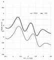
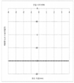
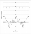
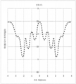
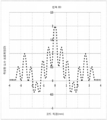
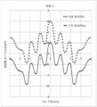
도 1은 제조된 광학 장치에 대한 공칭 도수 프로파일과 결과의 도수 프로파일의 예시적인 도면이다.
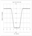
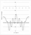
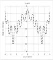
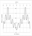
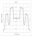
도 2는 선택된 관심 영역이 0.5 mm 내지 3.5 mm인, 도 1에 도시된 도수 프로파일의 예시적인 도면이다.
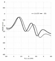
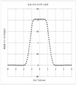
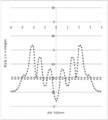
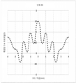
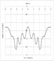
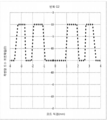
도 3은 측정된 프로파일이 0.75 디옵터(D) 오프셋을 갖는, 도 1에 도시된 도수 프로파일들의 예시적인 도면이다.
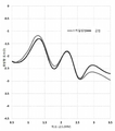
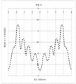
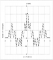
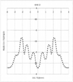
도 4는 측정된 프로파일이 0.75 디옵터 오프셋을 갖고 1.09 배로 스케일링되는, 도 1에 도시된 도수 프로파일들의 예시적인 도면이다.
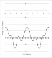
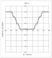
도 5는 측정된 프로파일이 0.75 디옵터 오프셋을 갖고 1.09 배로 스케일링되며, -0.65 디옵터의 비구면계수가 적용되는, 도 1에 도시된 도수 프로파일들의 예시적인 도면이다.
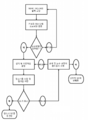
도 6은 제조된 광학 장치가 기결정된 품질 제어 메트릭스를 만족하는지를 결정하는 공정에 대한 예시적인 흐름도이다.
도 7a 내지 도 7c는 본원에서 사용될 때 통상적으로 간단한 도수 프로파일들로 여겨지는 예시적인 도수 프로파일들이다.
도 8a 내지 도 8w는 본원에서 사용될 때 통상적으로 복잡한 도수 프로파일들로 여겨지는 예시적인 도수 프로파일들이다.Notwithstanding other forms of disclosure herein that may fall within the scope of the present invention, certain embodiments will be described by way of example with reference to the accompanying drawings.
BRIEF DESCRIPTION OF THE DRAWINGS Figure 1 is an exemplary diagram of the nominal frequency profile and resulting frequency profile for an optical device manufactured.
Figure 2 is an exemplary view of the diopter profile shown in Figure 1 with the selected region of interest being 0.5 mm to 3.5 mm.
Figure 3 is an exemplary diagram of the diopter profiles shown in Figure 1 with the measured profile having a 0.75 diopter (D) offset.
Figure 4 is an exemplary diagram of the frequency profiles shown in Figure 1, wherein the measured profile is scaled 1.09 times with a 0.75 diopter offset.
Figure 5 is an exemplary diagram of the frequency profiles shown in Figure 1, wherein the measured profile has a 0.75 diopter offset and is scaled 1.09 times and an aspheric coefficient of -0.65 diopters is applied.
6 is an exemplary flow chart of a process for determining if a manufactured optical device satisfies a predetermined quality control metric.
Figures 7A-7C are exemplary frequency profiles that are typically considered simple frequency profiles when used herein.
8A-8W are exemplary frequency profiles that are typically considered to be complex frequency profiles when used herein.
콘택트렌즈들과 같은 제조된 광학 장치들은 다양한 위치들에서 장치의 교정 도수를 나타내는 도수 프로파일 및/또는 표면 프로파일을 포함할 수 있다. 일반적으로, 도수 프로파일 및/또는 표면 프로파일이 설계/선택되고, 광학 장치들(예를 들어, 콘택트렌즈들, 안구 내의(intra-ocular) 렌즈들)은 원하는 (공칭) 도수 프로파일 및/또는 복잡한 표면 프로파일을 포함하도록 제조된다. 특정 상황들에서, 상기 제조 공정은 이후, 원하는 (공칭) 도수 프로파일 및/또는 표면 프로파일을 갖는 광학 장치들의 제조에 사용되는 금형들/캐비티들의 생성을 포함할 수 있다. 통상의 기술자라면, 제조된 광학 장치의 도수 프로파일 및/또는 표면 프로파일이 공칭 도수 프로파일 및/또는 공칭 표면 프로파일과 동일하지 않을 것임을 쉽게 이해할 것이다. 이는 제조 공정에 수반되는 다양한 인자들에 기인한 것일 수 있다. 예를 들어, 일부 예에서, 상기 제조 장비는 충분히 정밀하지 않을 수 있고/있거나, 도수 프로파일 및/또는 표면 프로파일은, 장비가 일관성 및/또는 신뢰성 기준에서 취급할 수 있는 것 보다 더 복잡할 수 있다.Manufactured optical devices, such as contact lenses, may include a diopter profile and / or a surface profile that represents the calibrated frequency of the device at various locations. Generally, a dioptric and / or surface profile is designed / selected and optical devices (e.g., contact lenses, intra-ocular lenses) are placed in a desired (nominal) diopter profile and / Profile. In certain situations, the manufacturing process may then include the generation of molds / cavities used in the manufacture of optical devices having a desired (nominal) frequency profile and / or surface profile. As one of ordinary skill in the art will readily appreciate, the frequency profile and / or surface profile of the manufactured optical device will not be the same as the nominal frequency profile and / or the nominal surface profile. This may be due to various factors involved in the manufacturing process. For example, in some instances, the manufacturing equipment may not be sufficiently precise and / or the frequency profile and / or surface profile may be more complex than the equipment can handle in terms of consistency and / or reliability .
본원에서의 설명은 대체로, 제조된 광학 장치들의 도수 프로파일들을 논의하고 있고, 통상의 기술자들은, 제조된 광학 장치들의 표면 프로파일들의 품질을 결정하기 위해 동등한 및/또는 실질적으로 동등한 방법들 및 시스템들이 또한 적용될 수 있음을 이해해야 한다.The description herein generally discusses the frequency profiles of the manufactured optical devices and the ordinary skilled artisan will appreciate that equivalent and / or substantially equivalent methods and systems for determining the quality of the surface profiles of the manufactured optical devices It should be understood that the invention can be applied.
제조된 광학 장치의 도수 프로파일 내에서의 변화들은 적합할 수 있지만, 너무 많은 변화는 보통 바람직하지 않다. 특정 실시양태들에서, 공칭 도수 프로파일이 복잡할수록, 변화에 대한 공차는 낮아질 수 있다. 도 7 및 도 8은 상대적으로 간단한 도수 프로파일과 더 복잡한 도수 프로파일들 간의 차들 중 일부를 도시한다. 따라서, 도수 프로파일이 공칭 도수 프로파일에 대해 적합한 변화 범위 내에 있는지를 결정하기 위해, 제조된 장치의 도수 프로파일을 시험하는 것이 바람직할 수 있다.Changes in the frequency profile of the manufactured optical device may be suitable, but too many changes are usually undesirable. In certain embodiments, the more complex the nominal frequency profile, the lower the tolerance to change. Figures 7 and 8 show some of the differences between relatively simple and more complex frequency profiles. Therefore, it may be desirable to test the frequency profile of the manufactured device to determine if the frequency profile is within the appropriate range of variation for the nominal frequency profile.
본원에서의 설명은 대체로, 제조된 광학 장치들의 도수 프로파일들을 논의하지만, 통상의 기술자라면 동등한 및/또는 실질적으로 동등한 방법들과 시스템들도 광학 장치들의 제조에 사용되는 금형들 및/또는 캐비티들과 같은 제조된 금형들 및/또는 캐비티들에 적용될 수 있음을 이해해야 한다. 예시적인 실시양태들에서, 제조된 광학 장치의 도수 프로파일을 측정하고, 상기 측정된 도수 프로파일을 관심 영역 내의 공칭 도수 프로파일과 비교함으로써, 제조된 광학 장치의 도수 프로파일이 시험될 수 있다. 예시적인 실시양태들에서, 2개의 도수 프로파일들의 비교는 측정된 도수 프로파일의 파라메트릭 기술자를 사용하는 것을 포함할 수 있다. 예시적인 실시양태들에서, 상기 파라메트릭 기술자들은 공칭 도수 프로파일과 측정된 도수 프로파일 간 차들의 통계적 수량자를 최소화하기 위해(또는 적어도 감소시키거나 실질적으로 감소시키기 위해) 사용될 수 있다. 예시적인 실시양태들에서, 상기 통계적 수량자는 관심 영역 내에서 공칭 도수 프로파일과 상기 측정된 도수 프로파일 간 제곱 차들의 합일 수 있다. 측정된 광학 장치가 미리 결정된 특정 기준을 충족하는지 결정하기 위해, 통계적 수량자와 함께 하나 이상의 파라메트릭 기술자들이 사용될 수 있다.Although the description herein generally discusses the frequency profiles of manufactured optical devices, equivalent and / or substantially equivalent methods and systems, as is well known to those skilled in the art, are equally applicable to molds and / or cavities used in the manufacture of optical devices It should be understood that the present invention can be applied to molds and / or cavities manufactured in the same manner. In exemplary embodiments, the frequency profile of the manufactured optical device can be tested by measuring the frequency profile of the manufactured optical device and comparing the measured frequency profile with the nominal frequency profile in the region of interest. In the exemplary embodiments, the comparison of the two frequency profiles may include using a parametric descriptor of the measured frequency profile. In exemplary embodiments, the parametric descriptors may be used to minimize (or at least reduce or substantially reduce) the statistical quantities of differences between the nominal and measured frequency profiles. In exemplary embodiments, the statistical quantizer may be a sum of squared differences between the nominal frequency profile and the measured frequency profile within the region of interest. One or more parametric descriptors may be used with the statistical quantifier to determine whether the measured optical device meets a predetermined specific criterion.
도 1은 제조된 광학 장치에 대한 공칭 도수 프로파일과 결과의 도수 프로파일의 예시적인 도면이다. 도면으로부터 관찰될 수 있는 바와 같이, 제조된 광학 장치의 측정된 도수 프로파일은 공칭 도수 프로파일과 동일하지 않다. 본원에서 설명된 예시적인 실시양태들은 측정된 도수 프로파일이 공칭 도수 프로파일에 충분히 근접하여, 제조된 제품에 대해 확립된 품질 제어 가이드라인들을 충족하는지 결정하기 위한 방법들과 시스템들을 포함한다. 예시적인 실시양태들에서, 측정된 도수 프로파일이 품질 제어 가이드라인들에 충족하지 않으면, 제조된 광학 장치는 품질 제어 공정을 통과하지 못하여 폐기될 수 있거나, 또는 재분류될 수 있다. 예시적인 실시양태들에서, 측정된 프로파일이 통과하지 못한 이유와, 그리고 문제를 해결하기 위해 무엇이 이루어져야 하는지를 이해하기 위해, 근본 원인 분석/세부사항들이 추출될 수 있다.BRIEF DESCRIPTION OF THE DRAWINGS Figure 1 is an exemplary diagram of the nominal frequency profile and resulting frequency profile for an optical device manufactured. As can be observed from the figure, the measured frequency profile of the manufactured optical device is not identical to the nominal frequency profile. The exemplary embodiments described herein include methods and systems for determining whether a measured frequency profile is sufficiently close to a nominal frequency profile to meet established quality control guidelines for a manufactured product. In the exemplary embodiments, if the measured frequency profile does not meet the quality control guidelines, the manufactured optics may fail to pass the quality control process and may be discarded or reclassified. In the exemplary embodiments, root cause analysis / details can be extracted to understand why the measured profile did not pass and what should be done to solve the problem.
이를 달성하기 위해, 예시적인 실시양태들에서, 초기 단계는 제조된 광학 장치의 도수 프로파일을 측정하는 것일 수 있다. 도수 프로파일은 다양한 방식으로 측정될 수 있다. 예를 들어, 위상 시프팅 슐리렌법(phase shifting Schlieren method), 샤크 하트먼 파면 센서들(Shack Hartmann wavefront sensors), 프티코그래피법(ptychography) 또는 상업적으로 이용 가능한 다른 적합한 또는 주문 제작된 도수 매핑 기술들을 기반으로 하는, 상업적으로 이용 가능한 도수 매핑 장비들이 사용될 수 있다. To achieve this, in exemplary embodiments, the initial step may be to measure the frequency profile of the manufactured optical device. The frequency profile can be measured in a variety of ways. For example, a phase shifting Schlieren method, Shack Hartmann wavefront sensors, ptychography, or any other suitable or custom-made frequency mapping techniques available commercially Based, commercially available frequency mapping devices can be used.
도 1에는 예시적인 측정된 프로파일이 도시된다. 도수 프로파일을 측정한 이후, 다음 단계는 하나 이상의 관심 영역을 선택하고, 측정된 도수 프로파일과 공칭 도수 프로파일을 비교하는 것이다. 도 2는 선택된 관심 영역이 하프 코드(half chord) 상에서 0.5 mm 내지 3.5 mm인, 도 1에 도시된 도수 프로파일들의 도면이다. 도 2에 도시된 예시가 관심 영역을 0.5 mm 내지 3.5 mm로 도시하긴 하지만, 예시적인 실시양태들에서, 관심 영역은 전체 하프 코드 또는 임의의 다른 관련 영역일 수 있다. 예를 들어, 관심 영역은 0-3.5 mm, 0-3 mm, 0-2.5 mm, 0-2 mm, 0-1.5 mm, 0-1 mm, 0-0.5 mm, 0.5-3.5 mm, 0.5-3 mm, 0.5-2.5 mm, 0.5-2 mm, 0.5-1.5 mm, 0.5-1 mm, 1-3.5 mm, 1-3 mm, 1-2.5 mm, 1-2 mm, 1-1.5 mm, 1.5-3.5 mm, 1.5-3 mm, 1.5-2.5 mm, 1.5-2 mm, 2-3.5 mm, 2-3 mm, 2-2.5 mm, 2.5-3.5 mm, 2.5-3 mm 또는 3-3.5 mm일 수 있다.An exemplary measured profile is shown in FIG. After measuring the frequency profile, the next step is to select one or more regions of interest and compare the measured frequency profile to the nominal frequency profile. Figure 2 is a plot of the frequency profiles shown in Figure 1 with the selected region of interest being 0.5 mm to 3.5 mm on a half chord. Although the example shown in Fig. 2 shows the region of interest as 0.5 mm to 3.5 mm, in the exemplary embodiments, the region of interest may be a full Half Code or any other related region. For example, the area of interest may be 0-3.5 mm, 0-3 mm, 0-2.5 mm, 0-2 mm, 0-1.5 mm, 0-1 mm, 0-0.5 mm, 0.5-3.5 mm, 0.5-3 mm, 0.5-2.5 mm, 0.5-2 mm, 0.5-1.5 mm, 0.5-1 mm, 1-3.5 mm, 1-3 mm, 1-2.5 mm, 1-2 mm, 1-1.5 mm, 1.5-3.5 mm, 1.5-3 mm, 1.5-2.5 mm, 1.5-2 mm, 2-3.5 mm, 2-3 mm, 2-2.5 mm, 2.5-3.5 mm, 2.5-3 mm or 3-3.5 mm.
관심 영역을 선택한 후, 측정된 도수 프로파일에 대한 조정이 이루어질 수 있고, 제곱 차들의 합이 측정될 수 있다. 예시적인 실시양태들에서, 다른 통계적 수량자들(예를 들어, 프로크루스테스 거리(procrustes distance))도 활용될 수 있다. 예를 들어, 도 3은 0.75 디옵터 오프셋을 갖는, 측정된 프로파일의 예시적인 도면이다. 예시적인 실시양태들에서, 제곱 차들의 합을 최소화(또는 적어도 거의 최소화)하기 위해 오프셋이 선택될 수 있다. 예시적인 실시양태들에서 오프셋을 선택하는 공정은 반복적일 수 있다. 다시 말해, 오프셋이 선택될 수 있고, 이어서 제곱 차들의 결과의 합이 계산될 수 있다. 이러한 공정은, 제곱 차들의 합의 최소 값이 식별될 때까지 반복될 수 있다. 예시적인 실시양태들에서, 오프셋은 전체 관심 영역에 대해 단일 오프셋일 수 있고, 제곱 차들의 합은 복수의 측정 지점들에서 계산될 수 있다.After selecting the region of interest, adjustments to the measured frequency profile can be made, and the sum of squared differences can be measured. In the exemplary embodiments, other statistical quantities (e.g., procrustes distance) may be utilized. For example, Figure 3 is an exemplary view of a measured profile with 0.75 diopter offsets. In the exemplary embodiments, an offset may be selected to minimize (or at least substantially minimize) the sum of squared differences. The process of selecting the offset in the exemplary embodiments may be iterative. In other words, the offset can be selected, and then the sum of the results of the squared differences can be calculated. This process can be repeated until a minimum value of the sum of squared differences is identified. In the exemplary embodiments, the offset may be a single offset for the entire region of interest, and the sum of squared differences may be calculated at a plurality of measurement points.
오프셋을 적용한 후, 측정된 프로파일에 대해 추가적인 조정이 이루어질 수 있고, 제곱 차들의 결과의 합이 계산될 수 있다. 예를 들어, 도 4는 측정된 프로파일이 0.75 디옵터 오프셋을 갖고 하프 코드 축을 따라 1.09 배로 스케일링된, 도 1에 도시된 도수 프로파일들의 예시적인 도면이다. 예시적인 실시양태들에서, 제곱 차들의 합을 최소화(또는 적어도 거의 최소화)하기 위해 스케일이 선택될 수 있다. 예시적인 실시양태들에서, 스케일링 인자를 선택하는 공정은 반복적일 수 있다. 다시 말해, 스케일이 선택될 수 있고, 이어서 제곱 차들의 결과의 합이 계산될 수 있다. 이러한 공정은, 제곱 차들의 합의 최소 값이 식별될 때까지 반복될 수 있다. 예시적인 실시양태들에서, 스케일은 전체 관심 영역에 대한 단일 오프셋일 수 있고, 제곱 차들의 합은 복수의 측정 지점들에서 계산될 수 있다. 오프셋이 적용된 후 스케일이 적용되는 것으로 설명되었으나, 대안적인 순서도 적용될 수 있고, 상이한 조합의 파라미터들이 활용될 수 있다. 예시적인 실시양태들에서, 오프셋은 또한, 하프 코드를 따라 있을 수 있다. 예시적인 실시양태들에서, 오프셋은 측면 방향으로 시프트된 오프셋일 수 있다. After applying the offset, further adjustments can be made to the measured profile and the sum of the results of the squared differences can be calculated. For example, FIG. 4 is an exemplary diagram of the frequency profiles shown in FIG. 1, where the measured profile has a 0.75 diopter offset and is scaled 1.09 times along the half-code axis. In exemplary embodiments, a scale may be selected to minimize (or at least substantially minimize) the sum of squared differences. In exemplary embodiments, the process of selecting a scaling factor may be iterative. In other words, the scale can be selected, and then the sum of the results of the squared differences can be calculated. This process can be repeated until a minimum value of the sum of squared differences is identified. In exemplary embodiments, the scale may be a single offset for the entire region of interest, and the sum of squared differences may be calculated at a plurality of measurement points. Although it has been described that the scale is applied after the offset is applied, an alternative sequence may be applied, and different combinations of parameters may be utilized. In the exemplary embodiments, the offset may also be along a half-code. In the exemplary embodiments, the offset may be offset laterally offset.
오프셋 및 스케일링을 적용한 후, 측정된 프로파일에 대해 추가적인 조정이 이루어질 수 있다. 예를 들어, 도 5는 측정된 프로파일이 0.75 디옵터 오프셋을 갖고, 1.09 배로 스케일링되며, -0.65 디옵터의 비구면계수가 적용된, 도 1에 도시된 도수 프로파일들의 예시적인 도면이다. 예시적인 실시양태들에서, 비구면계수(또는 슬로프(slope) 교정)는 프로파일의 차(공칭 도수 프로파일 - 측정된 도수 프로파일)에 대한 2차 함수를 적용시킴으로써 계산될 수 있다. 통상의 기술자라면, 수화 중에 재료의 이방성 팽창 성질에 기인하여 비구면계수가 콘택트렌즈 내에 도입될 수 있다는 점을 쉽게 이해할 수 있다.After applying the offset and scaling, further adjustments may be made to the measured profile. For example, FIG. 5 is an exemplary diagram of the frequency profiles shown in FIG. 1 with the measured profile having a 0.75 diopter offset, scaled 1.09 times, and applying an aspheric coefficient of -0.65 diopters. In the exemplary embodiments, the aspherical coefficient (or slope calibration) can be calculated by applying a quadratic function to the difference in profile (nominal frequency profile - measured frequency profile). It will be readily understood by a person skilled in the art that aspheric coefficients can be introduced into the contact lens due to the anisotropic expansion properties of the material during hydration.
원하는 파라미터들과, 연관된 통계적 수량자를 획득한 후, 제조된 광학 제품이 품질 제어 검사를 통과하는지 결정하기 위해 파라미터들과 통계적 수량자들의 다양한 조합들이 활용될 수 있다. 예시적인 실시양태들에서, 제조된 광학 제품이 품질 제어 검사를 통과하지 못한 경우, 제품은 폐기되거나 재분류될 수 있다. 예를 들어, 예시적인 실시양태들에서 오프셋과, 대응하는 제곱 차들의 합은 제조된 광학 장치가 기결정된 품질 표준에 충족하는지 판단하는 데 활용될 수 있다. 표준은, 오프셋이 0.25 디옵터 미만이고 대응하는 제곱 차들의 합이 4 D2 미만인 경우, 장치가 표준을 통과하는 방식으로 수량화될 수 있다. 도 3의 측정된 도수 프로파일을 보면, 오프셋은 0.75 디옵터이다. 이에 따라, 제곱 차들의 합이 4 D2 미만이더라도, 장치는 품질 표준을 통과하지 못할 것이므로, 렌즈는 폐기될 수 있다. 대안적으로, 렌즈는 재분류될 수 있다. 이 상황에서, 제품이 충분히 근접할 수 있는 원하는 다른 공칭 도수 프로파일이 있을 수 있다. 이 상황에서, 오프셋에 대한 표준은 오프셋이 2.5 디옵터를 초과한 경우 제품이 통과하지 못한 것이지만, 오프셋이 0.75-1.25 디옵터인 경우 재분류되는 것일 수 있다. 도 3에서의 도수 프로파일의 경우, 이것이 원하는 다른 프로파일에 충분히 근접하기에, 장치는 재분류될 수 있다.After obtaining the desired parameters and associated statistical quantities, various combinations of parameters and statistical quantities can be utilized to determine if the manufactured optical product passes the quality control check. In exemplary embodiments, if the manufactured optical product fails the quality control check, the product may be discarded or reclassified. For example, in the exemplary embodiments, the offset and the sum of the corresponding squared differences can be utilized to determine whether the manufactured optical device meets a predetermined quality standard. The standard can be quantified in such a way that the device passes the standard if the offset is less than 0.25 diopters and the sum of the corresponding squared differences is less than 4 D 2 . Looking at the measured frequency profile of Figure 3, the offset is 0.75 diopters. Thus, even if the sum of squared differences is less than 4 D 2 , the device will not pass the quality standard, so the lens can be discarded. Alternatively, the lens may be reclassified. In this situation, there may be other desired nominal frequency profiles for which the product may be close enough. In this situation, the standard for offsets is that the product did not pass when the offset exceeded 2.5 diopters, but could be reclassified if the offset is between 0.75 and 1.25 diopters. In the case of the frequency profile in Fig. 3, the device can be reclassified because it is close enough to the desired other profile.
예시적인 실시양태들에서, 제조된 광학 장치가 기정의된 특정 품질 제어 요건들을 충족하는지 결정하기 위해, 오프셋, 스케일, 비구면계수(또는 슬로프 교정) 및 대응하는 통계적 수량자(예를 들어, 제곱 차들의 합)의 다양한 조합들이 활용될 수 있다.In exemplary embodiments, an offset, a scale, an asphericity coefficient (or slope correction) and a corresponding statistical quantizer (e.g., a squared difference ) May be utilized.
예시적인 실시양태들에서, 요건들을 충족하지 못한 장치들은 제조의 품질 제어 단계를 통과하지 못할 수 있거나, 대안적인 제품으로 재분류될 수 있다. 예시적인 실시양태들에서, 방법은 라벨 도수(label power, 예를 들어, 시력 보정(dioptric) 도수)를 제조된 광학 장치에 할당할 수 있다. 예를 들어, 방법은 장치가 품질 제어 단계의 요건을 충족하지 못한 경우, 라벨 도수를 할당하거나 또는 라벨 도수를 재할당할 수 있다.In the exemplary embodiments, devices that do not meet the requirements may not pass the quality control step of manufacturing, or may be reclassified as an alternative product. In exemplary embodiments, the method may assign a label power (e.g., dioptric power) to the manufactured optical device. For example, the method can assign a label frequency or reassign a label frequency if the device does not meet the requirements of the quality control step.
예시적인 실시양태들에서, 이러한 품질 제어 공정은 제조된 광학 제품의 제조 공정 중에 구현될 수 있다. 예시적인 실시양태들에서, 제조된 모든 광학 제품들은 제조 이후 또는 제조 공정 중 일부 단계에서 시험될 수 있다. 예시적인 실시양태들에서, 제조된 광학 제품들의 상당 부분이, 제조 이후 또는 제조 공정 중 일부 단계에서 시험될 수 있다. 예시적인 실시양태들에서, 제조된 광학 제품들 중 일부는 제조 이후 또는 제조 공정 중 일부 단계에서 시험될 수 있다. 예시적인 실시양태들에서, 1000개 중 적어도 1개, 500개 중 적어도 1개, 250개 중 적어도 1개, 100개 중 적어도 1개, 또는 20개 중 적어도 1개가, 제조 이후 또는 제조 공정 중 일부 단계에서 시험될 수 있다. 예시적인 실시양태들에서, 제품들이 하나 걸러 하나씩 시험될 수 있다. 예시적인 실시양태들에서, 제품들은 무작위(또는 의사난수) 방식으로 시험될 수 있다. 예시적인 실시양태들에서, 약 5개의 렌즈들 중 1개의 렌즈가 시험될 수 있다. 예를 들어, 2개의 렌즈들 중 1개의 렌즈, 3개의 렌즈들 중 1개의 렌즈, 4개의 렌즈들 중 1개의 렌즈, 5개의 렌즈들 중 1개의 렌즈, 6개의 렌즈들 중 1개의 렌즈, 7개의 렌즈들 중 1개의 렌즈, 8개의 렌즈들 중 1개의 렌즈, 9개의 렌즈들 중 1개의 렌즈 또는 10개의 렌즈들 중 1개의 렌즈가 시험될 수 있다. 예시적인 실시양태들에서, 품질 제어 공정은 실시간으로 또는 거의 실시간으로, 또는 품질 제어 공정이 구현되기 적합한 시간에 일어날 수 있다. 예시적인 실시양태들에서, 단일 렌즈는 실질적으로 실시간으로 검사될 수 있다.In exemplary embodiments, such a quality control process may be implemented during the manufacturing process of the manufactured optical product. In the exemplary embodiments, all of the optical articles produced may be tested after manufacture or at some stage during the manufacturing process. In the exemplary embodiments, a substantial portion of the manufactured optical products may be tested after manufacture or at some stage during the manufacturing process. In exemplary embodiments, some of the manufactured optical products may be tested after manufacture or at some stage during the manufacturing process. In exemplary embodiments, at least one of the 1000, at least one of the 500, at least one of the 250, at least one of the 100, or at least one of the 20 may be used after manufacturing or during some Step < / RTI > In the exemplary embodiments, the products may be tested one by one. In exemplary embodiments, the products may be tested in a random (or pseudo-random) manner. In exemplary embodiments, one of about five lenses may be tested. For example, one lens of two lenses, one lens of three lenses, one lens of four lenses, one lens of five lenses, one lens of six lenses, 7 One of the lenses, one of the eight lenses, one of the nine lenses, or one of the ten lenses may be tested. In exemplary embodiments, the quality control process may occur in real time or near real time, or at a time suitable for the quality control process to be implemented. In the exemplary embodiments, the single lens can be inspected substantially in real time.
덧붙여, 광학 제품들은 고속 제조 라인들(예를 들어, 분당 15, 20, 25, 30, 40, 45, 50, 55, 60, 65, 70, 75, 80, 85, 90, 95, 또는 100개의 광학 장치들을 생산할 수 있는 제조 라인) 상에서 제조될 수 있다. 이 상황에서, 시험은 라인의 속도에 상당한 영향을 미치는 일 없이, 실질적으로 실시간으로 수행되거나 수행되지 않을 수 있다. 예를 들어, 제조 상황에서, 본원에서 설명된 시험 절차는 1%, 2%, 3%, 4%, 5%, 10%, 또는 15% 등 미만으로 제조 라인의 출력을 감소시킬 수 있다.In addition, optical products can be used in high-speed manufacturing lines (e.g., 15, 20, 25, 30, 40, 45, 50, 55, 60, 65, 70, 75, 80, 85, 90, 95, A manufacturing line capable of producing optical devices). In this situation, the test may or may not be performed substantially in real time, without significantly affecting the speed of the line. For example, in a manufacturing situation, the test procedures described herein may reduce the output of a manufacturing line to less than 1%, 2%, 3%, 4%, 5%, 10%, or 15%
도 6은 제조된 광학 장치가 기결정된 품질 제어 메트릭스를 만족하는지를 결정하는 공정의 예시적인 흐름도이다. 예시적인 실시양태들에서, 제조된 광학 장치는 Lambda-X NIMO TR1504를 사용하여 측정될 수 있다. 측정 이후, 프로파일은 비교 시스템으로 로딩될 수 있다. 시스템은 초기 검사를 수행하여 측정된 프로파일이 유효한지 결정할 수 있다. 프로파일이 유효한 것으로 시스템이 결정하면, 측정된 프로파일이 선택되고, 공칭 도수 프로파일과 비교된다. 비교 이후, 시스템은 측정된 프로파일이 공칭 프로파일에 충분히 유사하여(예를 들어, 특정 공차들 내에서), 정의된 품질 파라미터들을 충족하는지 결정한다. 품질 제어 표준이 충족되지 않는 경우, 상기 공정은 설계 및 도수가 올바르게 설정되었는지를 재검토한다. 이 경우, 제조된 장치는 품질 검사를 통과하지 못한다. 파라미터들이 교정되지 않을 경우, 이들은 재설정되고, 다시 비교가 수행된다. 제조된 광학 장치가 품질 제어 표준에 충족하는 경우, 이는 품질 검사를 통과한다.6 is an exemplary flow chart of a process for determining if a manufactured optical device satisfies a predetermined quality control metric. In the exemplary embodiments, the manufactured optical device can be measured using Lambda-X NIMO TR1504. After the measurement, the profile can be loaded into the comparison system. The system can perform an initial check to determine if the measured profile is valid. If the system determines that the profile is valid, the measured profile is selected and compared to the nominal frequency profile. After comparison, the system determines that the measured profile is sufficiently similar to the nominal profile (e.g., within certain tolerances) to meet the defined quality parameters. If the quality control standard is not met, the process reviews whether the design and frequency are set correctly. In this case, the manufactured device does not pass the quality inspection. If the parameters are not calibrated, they are reset and the comparison is again performed. If the manufactured optical device meets the quality control standard, it passes the quality inspection.
예시적인 실시양태들에서, 시스템은 MATLAB 또는 유사한 소프트웨어를 이용하여, 본원에서 설명된 비교를 수행하도록 프로그래밍된 프로세서를 포함할 수 있다. 예시적인 실시양태들에서, 사용자 인터페이스는 그래픽 유저 인터페이스일 수 있다.In exemplary embodiments, the system may include a processor programmed to perform the comparisons described herein using MATLAB or similar software. In exemplary embodiments, the user interface may be a graphical user interface.
예시적인 실시양태들에서, 시스템은 Lambda-X NIMO 장비로부터 측정된 값들과, 렌즈 프로파일에 대한 공칭 광학 도수 프로파일을 비교하고, 측정된 값들이 공칭 값들의 공차 내에 있는지 결정하며, 라벨 도수와 함께 통과/실패 결과를 보고할 수 있다.In exemplary embodiments, the system compares the measured values from the Lambda-X NIMO equipment with the nominal optical power profile for the lens profile, determines whether the measured values are within the tolerances of the nominal values, / Can report failure results.
본원에서 논의되는 바와 같이, 예시적인 실시양태들에서, 품질 제어를 위해 사용되는 기준은 측정된 프로파일과 공칭 프로파일 사이의 제곱 차들의 합(SSD)일 수 있다(예를 들어, SSD가 25 D2, 20 D2, 15 D2, 10 D2, 또는 5 D2를 초과할 경우 실패). 이러한 기준은 SSD 결과를 합계된 지점들의 개수로 나눔으로써 변경하여, 그것이 선택된 영역 또는 관심 영역에 독립적이 되게 할 수 있다. 대안적으로, 측정된 및 공칭 프로파일들 사이의 면적은 관심 영역(들) 위에서 계산될 수 있다. 그리고 나서, 이 면적은 선택된 관심 영역(들)의 직경을 따라 전체 거리들로 나누어서, 시력 보정 단위에서의 평균 오차를 획득할 수 있다. 이들 중 임의의 예시들에서, 예를 들어, 직경 범위를 따라 특정 영역들에 추가적인 가중치를 주는 가중 인자가 적용될 수 있다. 예시적인 실시양태들에서, 상기 시스템은 또한 스케일(예를 들어, 공칭 프로파일과 비교할 때 측정된 프로파일의 직경을 따라 신장 또는 축소 또는 오프셋), 비구면계수(또는 슬로프 교정)(예를 들어, 측정된 및 공칭 프로파일 간의 선형 (경사) 또는 타원형 오차) 및/또는, 공칭 도수 프로파일과 비교한 측정된 도수 프로파일 내의 피크 대 골 비율들에 대한 데이터의 적합한 조합들을 위해 메트릭스를 반환할 수 있다. 예시적인 실시양태들에서, 메트릭스는 동일하게 이격된(예를 들어, 0.005, 0.0075, 0.01, 0.015 또는 0.02 mm) 샘플링 지점들에서 결정될 수 있다.As discussed herein, in the exemplary embodiments, the criteria used for quality control may be the sum of the squared differences (SSD) between the measured profile and the nominal profile (e.g., the SSD is 25 D 2 , 20 D 2 , 15 D 2 , 10 D 2 , or 5 D 2 ). This criterion can be changed by dividing the SSD result by the number of points summed to make it independent of the selected area or area of interest. Alternatively, the area between the measured and nominal profiles can be calculated on the region of interest (s). This area can then be divided by the total distances along the diameter of the selected region of interest (s) to obtain an average error in the vision correction unit. In any of these examples, for example, a weighting factor may be applied that gives additional weighting to specific regions along the diameter range. In exemplary embodiments, the system may also be configured to provide a scale (e.g., stretching or shrinking or offset along the diameter of the measured profile as compared to a nominal profile), an asphericity coefficient (or slope correction) For example, a linear (slope) or elliptical error between the nominal profile and the nominal profile) and / or peak to bone ratios in the measured frequency profile compared to the nominal frequency profile. In the exemplary embodiments, the metrics may be determined at equally spaced sampling points (e.g., 0.005, 0.0075, 0.01, 0.015 or 0.02 mm).
예시적인 실시양태들에서, 메트릭스/변수는 하기 표 내의 메트릭스의 조합들을 포함할 수 있다. In the exemplary embodiments, the metrics / variables may include combinations of metrics in the following table.

예시적인 실시양태들에서, 사용자들은 비교 계산을 변경하지 못할 수 있다. 그러나, 비교 내의 특정 파라미터들은 사용자에 의해 구성가능 할 수 있다. 예를 들어, 일부 실시양태들에서, 레이블 도수는 공칭 또는 목표 도수(aim power)로부터, ± 0.10, 0.20, 0.25, 0.30, 0.40 또는 0.50 D만큼 조정가능 할 수 있다.In the exemplary embodiments, users may not be able to change the comparison calculation. However, certain parameters within the comparison may be configurable by the user. For example, in some embodiments, the label frequency may be adjustable from nominal or aim power by +/- 0.10, 0.20, 0.25, 0.30, 0.40, or 0.50 D.
예시적인 실시양태들에서, 공칭 광학 도수 프로파일들은 시스템 내로 하드코딩(hardcoded)될 수 있고, 시스템은 사용자에 의해 제공된 프로파일들을 수락할 수 있다.In exemplary embodiments, the nominal optical power profiles can be hardcoded into the system, and the system can accept the profiles provided by the user.
본원에서 설명된 예시적인 실시양태들이 일반적으로, 전체 광학 구역 내의 도수 분포가 1차원 도수 플롯으로 감소되도록 허용하는 일부 회전 대칭의 형태를 가진 도수 프로파일을 설명하였으나, 광학 장치들(콘택트렌즈들)은 회전 대칭이 아닐 수 있다. 본원에서 설명된 시스템들, 방법들 및 장치들이 여전히 적용 가능하다. 예를 들어, 콘택트렌즈의 전면 또는 후면은 원환체 형태이어서, 도 8s에 도시된 것처럼 상이한 경선(meridian)들 사이에 기준 도수 변수들을 만들 수 있다. 다른, 더 복잡한 변형들도 생각될 수 있다. 시스템들, 방법들 및 장치들의 기본 개념이 여전히 적용될 수 있다(예를 들어, 하나는 상이한 관심 경선들을 별도로 분석한 후, 전체 결과를 결합하는 것이다)Although the exemplary embodiments described herein generally describe a diopter profile with some rotationally symmetric shape that allows the frequency distribution within the entire optical zone to be reduced to a one-dimensional diopter plot, the optics (contact lenses) It may not be rotationally symmetrical. The systems, methods and apparatuses described herein are still applicable. For example, the front or back of the contact lens may be torus-shaped so as to create reference frequency variables between different meridians, as shown in Figure 8S. Other, more complex variants may be conceivable. The basic concepts of systems, methods and apparatuses can still be applied (for example, one analyzing different interest meridians separately and then combining the overall results)
예시적인 실시양태들에서, 상기 시스템은 통과/실패 결과 및/또는 라벨 도수를 5, 6, 7, 8, 9, 10, 11, 12, 13, 14, 15, 16, 17, 18, 19, 20, 21, 22, 23, 24 또는 25초 내에 제공하도록 구성될 수 있다. 예시적인 실시양태들에서, 상기 시스템은 통과/실패 결과 및/또는 라벨 도수를 50, 60, 70, 80, 90, 100, 110, 120, 130, 140, 150, 160, 170, 180, 190, 200, 210, 220, 230, 240, 250, 300, 350, 400, 450, 또는 500 밀리초 내에 제공하도록 구성될 수 있다.In exemplary embodiments, the system may be configured to provide a pass / fail result and / or a label frequency of 5, 6, 7, 8, 9, 10, 11, 12, 13, 14, 15, 16, 17, 20, 21, 22, 23, 24, or 25 seconds. In exemplary embodiments, the system may be configured to provide a pass / fail result and / or a label frequency of 50, 60, 70, 80, 90, 100, 110, 120, 130, 140, 150, 160, 170, 180, 190, 200, 210, 220, 230, 240, 250, 300, 350, 400, 450, or 500 milliseconds.
본원에서 실시양태들을 나타내고 설명하였지만, 통상의 기술자에게, 이러한 실시양태들이 예시를 위해서만 제공된 것임이 명백할 것이다. 이하의 청구항들은 발명의 범위를 정의하고, 이들 청구항의 범위 내의 방법과 구조 및 그 균등물이 이들에 포함되는 것을 의도하는 것이다.While the embodiments have been illustrated and described herein, it will be apparent to those of ordinary skill in the art that such embodiments are provided by way of example only. It is intended that the following claims define the scope of the invention and that methods, structures and equivalents within the scope of these claims be encompassed therein.
Claims (34)
상기 제조된 광학 장치, 금형 및/또는 캐비티의 상기 도수 프로파일 및/또는 상기 표면 프로파일을 측정하는 단계;
상기 제조된 광학 장치, 금형 및/또는 캐비티의 측정된 도수 프로파일 및/또는 측정된 표면 프로파일로부터 하나 이상의 관심 영역들을 식별하는 단계;
상기 대응하는 공칭 도수 프로파일 및/또는 표면 프로파일과 오프셋된 측정된(offset measured) 도수 프로파일 간 유사도를 수량화하는 통계적 수량자(statistical quantifier)를 실질적으로 최소화하기 위해, 상기 측정된 도수 프로파일 및/또는 상기 측정된 표면 프로파일에 대한 적어도 하나의 오프셋(X 및/또는 Y)을 결정하는 단계;
상기 오프셋 및 상기 통계적 수량자들을 기정의된 품질 제어 메트릭스(metrics)와 비교하는 단계; 및
상기 비교에 적어도 부분적으로 기반하여, 상기 측정된 도수 프로파일이 상기 기정의된 품질 제어 메트릭스를 충족하는 지 결정하는 단계
를 포함하는 유사도 평가 방법.The refractive index profile and / or the surface profile of the manufactured optical device, the mold and / or the cavity, and the corresponding dioptric profile of the manufactured optical device, the mold and / or the cavity and / And / or a similarity between nominal surface profiles, the method comprising:
Measuring the frequency profile and / or the surface profile of the manufactured optical device, the mold and / or the cavity;
Identifying one or more regions of interest from a measured frequency profile and / or a measured surface profile of the manufactured optical device, mold and / or cavity;
In order to substantially minimize a statistical quantifier that quantifies the similarity between the corresponding nominal and / or surface profile and an offset measured frequency profile, the measured frequency profile and / Determining at least one offset (X and / or Y) for the measured surface profile;
Comparing the offset and the statistical quantities to predefined quality control metrics; And
Determining, based at least in part on the comparison, whether the measured frequency profile meets the predefined quality control metric
Of the similarity.
상기 측정된 도수 프로파일 및/또는 측정된 표면 프로파일이 상기 기정의된 품질 제어 메트릭스를 충족하지 않는 경우, 상기 제조된 광학 장치, 금형 및/또는 캐비티를 다른 공칭 도수 프로파일, 도수 및/또는 표면 프로파일에 연관시킬지를 결정하는 단계를 더 포함하는 유사도 평가 방법.The method according to claim 1,
If the measured frequency profile and / or the measured surface profile does not meet the predefined quality control metric, then the manufactured optical device, mold and / or cavity may be subjected to other nominal frequency profiles, frequency and / And determining whether to associate the similarity measure.
상기 공칭 도수 프로파일 및/또는 공칭 표면 프로파일과, 스케일링 및 오프셋된 측정된 도수 프로파일 및/또는 스케일링 및 오프셋된 측정된 표면 프로파일 간 유사도를 수량화하는 통계적 수량자를 실질적으로 최소화하기 위해, 상기 오프셋된 측정된 도수 프로파일 및/또는 오프셋된 측정된 표면 프로파일에 스케일링 인자를 적용하는 단계; 및
상기 스케일링 인자, 오프셋 및 상기 통계적 수량자를 기정의된 품질 제어 메트릭스와 비교하는 단계를 더 포함하는 유사도 평가 방법.3. The method according to claim 1 or 2,
In order to substantially minimize statistical quantities that quantify the nominal and / or nominal surface profile and the similarity between scaled and offset measured frequency profiles and / or scaled and offset measured surface profiles, the offset measured Applying a scaling factor to a frequency profile and / or an offset measured surface profile; And
And comparing the scaling factor, offset and the statistical quantizer to a predefined quality control metric.
상기 공칭 도수 프로파일 및/또는 공칭 표면 프로파일과, 교정, 스케일링 및 오프셋된 측정된 도수 프로파일 및/또는 교정, 스케일링 및 오프셋된 측정된 표면 프로파일 간 유사도를 수량화하는 통계적 수량자를 실질적으로 최소화하기 위해 상기 스케일링 및 오프셋된 측정된 도수 프로파일 및/또는 스케일링 및 오프셋된 측정된 표면 프로파일에 비구면계수 교정(또는 슬로프 교정)을 적용하는 단계; 및
회전(rotation), 스케일링 인자, 오프셋 및 상기 통계적 수량자와 기정의된 품질 제어 메트릭스를 비교하는 단계를 더 포함하는 유사도 평가 방법.4. The method according to one or more of claims 1 to 3,
In order to substantially minimize the statistical quantities that quantify the nominal and / or nominal surface profile and the similarity between the calibrated, scaled and offset measured frequency profiles and / or calibration, scaled and offset measured surface profiles, the scaling And applying an aspherical coefficient correction (or slope correction) to the offset measured frequency profile and / or the scaled and offset measured surface profile; And
A rotation, a scaling factor, an offset, and comparing the statistical quantifier with a predefined quality control metric.
상기 제조된 광학 장치, 금형 및/또는 캐비티의 상기 도수 프로파일 및/또는 표면 프로파일을 수신하기 위한 입력부; 및
프로세서를 포함하고,
상기 프로세서는
상기 제조된 광학 장치, 금형 및/또는 캐비티의 측정된 도수 프로파일 및 측정된 표면 프로파일로부터 적어도 하나의 관심 영역을 식별하고;
상기 공칭 도수 프로파일 및/또는 공칭 표면 프로파일과, 오프셋된 측정된 도수 프로파일 및/또는 오프셋된 측정된 표면 프로파일 간의 유사도를 수량화하기 위한 통계적 수량자를 실질적으로 최소화하기 위해 상기 측정된 도수 프로파일 및 측정된 표면 프로파일에 대한 적어도 하나의 오프셋(X 및/또는 Y)을 결정하고;
상기 오프셋 및 상기 통계적 수량자와 기정의된 품질 제어 메트릭스를 비교하며;
상기 비교에 적어도 부분적으로 기반하여 상기 측정된 도수 프로파일이 상기 기정의된 품질 제어 메트릭스를 충족하는지 결정하도록 구성된
유사도 평가 시스템.The refractive index profile and / or the surface profile of the manufactured optical device, the mold and / or the cavity, and the corresponding dioptric profile of the manufactured optical device, the mold and / or the cavity and / And / or a surface profile similarity evaluation system, comprising:
An input for receiving the frequency profile and / or the surface profile of the manufactured optical device, the mold and / or the cavity; And
A processor,
The processor
Identifying at least one region of interest from the measured dioptric and measured surface profiles of the manufactured optical device, mold and / or cavity;
The measured frequency profile and the measured surface profile to substantially minimize statistical quantities for quantifying the degree of similarity between the nominal frequency profile and / or the nominal surface profile and the offset measured frequency profile and / Determine at least one offset (X and / or Y) for the profile;
Compare the offset and the statistical quantifier to a predefined quality control metric;
And to determine whether the measured frequency profile meets the predefined quality control metric based at least in part on the comparison
Similarity Evaluation System.
상기 프로세서는,
상기 공칭 도수 프로파일 및/또는 공칭 표면 프로파일과, 스케일링 및 오프셋된 측정된 도수 프로파일 및/또는 스케일링 및 오프셋된 측정된 표면 프로파일 간 유사도를 수량화하는 통계적 수량자를 실질적으로 최소화하기 위해, 스케일링 인자를 상기 오프셋된 측정된 도수 프로파일 및/또는 오프셋된 측정된 표면 프로파일에 적용하고, 상기 스케일링 인자, 상기 오프셋 및 상기 통계적 수량자와 기정의된 품질 제어 메트릭스를 비교하도록 더 구성되는 유사도 평가 시스템.20. The method according to claim 18 or 19,
The processor comprising:
In order to substantially minimize statistical quantities that quantify the nominal and / or nominal surface profile and the similarity between scaled and offset measured frequency profiles and / or scaled and offset measured surface profiles, To the measured and / or offset measured surface profile, and to compare the scaling factor, the offset, and the statistical quantifier to a predefined quality control metric.
상기 공칭 도수 프로파일 및/또는 공칭 표면 프로파일과 교정, 스케일링 및 오프셋된 측정된 도수 프로파일 및/또는 교정, 스케일링 및 오프셋된 측정된 표면 프로파일 간의 유사도를 수량화하는 통계적 수량자를 실질적으로 최소화하기 위해, 비구면계수 교정(또는 슬로프 교정)을 상기 스케일링 및 오프셋된 측정된 도수 프로파일 및/또는 스케일링 및 오프셋된 측정된 표면 프로파일에 적용하고,
상기 회전, 스케일링 인자, 오프셋 및 상기 통계적 수량자와 기정의된 품질 제어 메트릭스를 비교하도록 더 구성되는 유사도 평가 시스템.21. A processor as claimed in any one of claims 18 to 20,
In order to substantially minimize the statistical quantities that quantify the similarity between the nominal and / or nominal surface profile and the calibrated, scaled and offset measured frequency profiles and / or calibration, scaling, and offset measured surface profiles, Applying a calibration (or slope calibration) to the scaled and offset measured frequency and / or scaled and offset measured surface profile,
And to compare the rotation, scaling factor, offset and the predefined quality control metric with the statistical quantifier.
상기 비교는 상기 제조된 광학 장치, 금형 및/또는 캐비티의 제조 공정 중에 수행되는 유사도 평가 시스템.23. The method according to one of claims 18 to 22,
Wherein the comparison is performed during the manufacturing process of the optical device, the mold, and / or the cavity.
Applications Claiming Priority (3)
| Application Number | Priority Date | Filing Date | Title |
|---|---|---|---|
| US201462078310P | 2014-11-11 | 2014-11-11 | |
| US62/078,310 | 2014-11-11 | ||
| PCT/AU2015/050700 WO2016074034A2 (en) | 2014-11-11 | 2015-11-11 | Systems and methods for determining the quality of a reproduced (manufactured) optic device |
Publications (1)
| Publication Number | Publication Date |
|---|---|
| KR20170080696A true KR20170080696A (en) | 2017-07-10 |
Family
ID=55955207
Family Applications (1)
| Application Number | Title | Priority Date | Filing Date |
|---|---|---|---|
| KR1020177015920A KR20170080696A (en) | 2014-11-11 | 2015-11-11 | Systems and methods for determining the quality of a reproduced (manufactured) optic device |
Country Status (10)
| Country | Link |
|---|---|
| US (2) | US10352816B2 (en) |
| EP (1) | EP3218685B1 (en) |
| JP (3) | JP2018503100A (en) |
| KR (1) | KR20170080696A (en) |
| CN (1) | CN107110740B (en) |
| ES (1) | ES2887113T3 (en) |
| HU (1) | HUE055799T2 (en) |
| SG (1) | SG11201703751YA (en) |
| TW (1) | TWI679466B (en) |
| WO (1) | WO2016074034A2 (en) |
Families Citing this family (5)
| Publication number | Priority date | Publication date | Assignee | Title |
|---|---|---|---|---|
| SG11201703751YA (en) * | 2014-11-11 | 2017-06-29 | Holden Brien Vision Inst | Systems and methods for determining the quality of a reproduced (manufactured) optic device |
| US10557773B2 (en) | 2016-05-18 | 2020-02-11 | Jand, Inc. | Fixtureless lensmeter system |
| US10036685B2 (en) * | 2016-05-18 | 2018-07-31 | Jand, Inc. | Fixtureless lensmeter and methods of operating same |
| US11488239B2 (en) | 2019-08-26 | 2022-11-01 | Warby Parker Inc. | Virtual fitting systems and methods for spectacles |
| CN115803750B (en) | 2020-04-15 | 2024-01-30 | 沃比帕克公司 | Virtual try-on system for glasses using a frame of reference |
Family Cites Families (26)
| Publication number | Priority date | Publication date | Assignee | Title |
|---|---|---|---|---|
| DE69402281T2 (en) * | 1993-09-17 | 1997-09-04 | Essilor Int | Method and device for the absolute measurement of the geometric or optical structure of an optical component |
| CN1133073C (en) * | 1998-07-27 | 2003-12-31 | 松下电器产业株式会社 | Method and device for measuring optical element aberration used with optical device |
| US6750958B1 (en) * | 1999-06-09 | 2004-06-15 | Optikos Corporation | Automated optical measurement apparatus and method |
| US20050075125A1 (en) * | 2002-01-21 | 2005-04-07 | Bada Anna Marina | Method and mobile station to perform the initial cell search in time slotted systems |
| JP4358733B2 (en) | 2002-05-16 | 2009-11-04 | Hoya株式会社 | Evaluation method and evaluation apparatus for spectacle lens or spectacle lens molding mold |
| US20070247639A1 (en) * | 2004-05-10 | 2007-10-25 | Koninklijke Philips Electronics, N.V. | Device and Method for Optical Precision Measurement |
| JP2006105717A (en) * | 2004-10-04 | 2006-04-20 | Matsushita Electric Ind Co Ltd | Height data estimation method, height data estimation program and three-dimensional shape measuring device |
| JP2007170888A (en) * | 2005-12-20 | 2007-07-05 | Olympus Corp | Optical element testing device |
| JP2007281003A (en) * | 2006-04-03 | 2007-10-25 | Canon Inc | Measuring method and device, and exposure device |
| US7416300B2 (en) * | 2006-05-25 | 2008-08-26 | Coopervision International Holding Company, Lp | Measurement of lenses and lens molds using optical coherence tomography |
| EP2097712B1 (en) * | 2006-12-21 | 2014-10-15 | Johnson and Johnson Vision Care, Inc. | Interferometry testing of lenses, and systems and devices for same |
| JP2008172004A (en) * | 2007-01-11 | 2008-07-24 | Nikon Corp | Aberration evaluating method, adjusting method, exposure device, exposure method and device manufacturing method |
| BRPI0807743A2 (en) * | 2007-02-14 | 2014-06-17 | Inst Eye Res Ltd | CHARACTERIZATION OF OPTICAL SYSTEMS |
| JP2009031109A (en) * | 2007-07-26 | 2009-02-12 | Tokyo Institute Of Technology | Method for analyzing image |
| JP5107358B2 (en) | 2007-08-31 | 2012-12-26 | Hoya株式会社 | Lens evaluation method, lens evaluation apparatus, lens manufacturing method, and lens characteristic display method |
| CN101842684B (en) * | 2007-10-31 | 2013-10-23 | Hoya株式会社 | Spectacle lens evaluating method, spectacle lens designing method using same, spectacle lens manufacturing method, spectacle lens manufacturing system, and spectacle lens |
| JP2009181689A (en) * | 2008-01-30 | 2009-08-13 | Jds Uniphase Corp | Optical pickup unit having two-mirror phase shifter |
| JP5615799B2 (en) * | 2009-02-27 | 2014-10-29 | Hoya株式会社 | Method for manufacturing lens mold and method for manufacturing spectacle lens |
| JP5540213B2 (en) * | 2010-12-20 | 2014-07-02 | 東海光学株式会社 | Eyeglass lens evaluation method |
| WO2013119775A1 (en) * | 2012-02-10 | 2013-08-15 | Johnson & Johnson Vision Care, Inc. | Method and apparatus for determining a thickness profile of an ophthalmic lens using a single point thickness and refractive index measurements |
| TWI588560B (en) * | 2012-04-05 | 2017-06-21 | 布萊恩荷登視覺協會 | Lenses, devices, methods and systems for refractive error |
| US9201250B2 (en) * | 2012-10-17 | 2015-12-01 | Brien Holden Vision Institute | Lenses, devices, methods and systems for refractive error |
| CN104768499B (en) * | 2012-10-17 | 2017-06-23 | 华柏恩视觉研究中心 | For ametropic eyeglass, device, method and system |
| US9671618B2 (en) | 2012-11-14 | 2017-06-06 | Essilor International (Compagnie Generale D'optique) | Method of determining optical parameters of an ophthalmic lens |
| GB2508219A (en) * | 2012-11-26 | 2014-05-28 | Taylor Hobson Ltd | Analysing and machining an optical profile |
| SG11201703751YA (en) * | 2014-11-11 | 2017-06-29 | Holden Brien Vision Inst | Systems and methods for determining the quality of a reproduced (manufactured) optic device |
-
2015
- 2015-11-11 SG SG11201703751YA patent/SG11201703751YA/en unknown
- 2015-11-11 HU HUE15858689A patent/HUE055799T2/en unknown
- 2015-11-11 EP EP15858689.1A patent/EP3218685B1/en active Active
- 2015-11-11 CN CN201580072477.3A patent/CN107110740B/en not_active Expired - Fee Related
- 2015-11-11 TW TW104137222A patent/TWI679466B/en not_active IP Right Cessation
- 2015-11-11 ES ES15858689T patent/ES2887113T3/en active Active
- 2015-11-11 KR KR1020177015920A patent/KR20170080696A/en unknown
- 2015-11-11 JP JP2017543853A patent/JP2018503100A/en active Pending
- 2015-11-11 US US15/526,205 patent/US10352816B2/en active Active
- 2015-11-11 WO PCT/AU2015/050700 patent/WO2016074034A2/en active Application Filing
-
2019
- 2019-06-03 US US16/430,060 patent/US10670495B2/en active Active
-
2021
- 2021-01-06 JP JP2021000650A patent/JP2021060420A/en active Pending
-
2023
- 2023-02-27 JP JP2023027890A patent/JP2023078153A/en active Pending
Also Published As
| Publication number | Publication date |
|---|---|
| CN107110740A (en) | 2017-08-29 |
| TWI679466B (en) | 2019-12-11 |
| WO2016074034A3 (en) | 2016-06-23 |
| JP2021060420A (en) | 2021-04-15 |
| US10670495B2 (en) | 2020-06-02 |
| US20190391039A1 (en) | 2019-12-26 |
| EP3218685A4 (en) | 2018-07-04 |
| HUE055799T2 (en) | 2021-12-28 |
| EP3218685A2 (en) | 2017-09-20 |
| US20170322110A1 (en) | 2017-11-09 |
| JP2018503100A (en) | 2018-02-01 |
| EP3218685B1 (en) | 2021-06-16 |
| JP2023078153A (en) | 2023-06-06 |
| CN107110740B (en) | 2021-04-30 |
| US10352816B2 (en) | 2019-07-16 |
| SG11201703751YA (en) | 2017-06-29 |
| TW201632953A (en) | 2016-09-16 |
| ES2887113T3 (en) | 2021-12-21 |
| WO2016074034A2 (en) | 2016-05-19 |
Similar Documents
| Publication | Publication Date | Title |
|---|---|---|
| US10670495B2 (en) | Systems and methods for determining the quality of a reproduced (manufactured) optic device | |
| JP6381571B2 (en) | Phoropter | |
| US8876290B2 (en) | Objective quality metric for ocular wavefront measurements | |
| KR102001808B1 (en) | A method for determining an improved design for a progressive lens taking into account a higher order aberration of the eye | |
| US9645412B2 (en) | Customized lens device and method | |
| JP2021060420A5 (en) | ||
| KR101723800B1 (en) | Lens design simplification process | |
| JP2020536282A5 (en) | ||
| JP2018503100A5 (en) | ||
| US9709823B2 (en) | Method for transforming a progressive ophthalmic surface | |
| CN106932921B (en) | Progressive additional free surface lens method of evaluating performance | |
| JP2021051006A (en) | Optical characteristic evaluation method, spectacle lens manufacturing method, and spectacle lens | |
| JP2007225984A (en) | Improved tolerance determining method for inspection of progressive refractive power spectacle lens | |
| Zhang et al. | Research and analysis on new test lenses for calibration of focimeters used for measuring contact lenses | |
| KR20230109686A (en) | Method, apparatus, computer program and system for conversion of measurements of ophthalmic lenses | |
| CN113995552A (en) | Method for manufacturing artificial lens for precise surface shape control and artificial lens | |
| Vishnyakov et al. | Checking and calibration equipment for ophthalmologic refractometers | |
| CN114097066A (en) | Data-driven misalignment parameter configuration and measurement system and method | |
| Wattellier et al. | Wave Front Sensor Solution for Optical design prototyping and manufacture check in production |