KR20170080481A - Multilane vehicle speed detecting system - Google Patents
Multilane vehicle speed detecting system Download PDFInfo
- Publication number
- KR20170080481A KR20170080481A KR1020160173721A KR20160173721A KR20170080481A KR 20170080481 A KR20170080481 A KR 20170080481A KR 1020160173721 A KR1020160173721 A KR 1020160173721A KR 20160173721 A KR20160173721 A KR 20160173721A KR 20170080481 A KR20170080481 A KR 20170080481A
- Authority
- KR
- South Korea
- Prior art keywords
- vehicle
- image
- cropping
- speed
- license plate
- Prior art date
Links
Images


Classifications
-
- G—PHYSICS
- G08—SIGNALLING
- G08G—TRAFFIC CONTROL SYSTEMS
- G08G1/00—Traffic control systems for road vehicles
- G08G1/01—Detecting movement of traffic to be counted or controlled
- G08G1/052—Detecting movement of traffic to be counted or controlled with provision for determining speed or overspeed
- G08G1/054—Detecting movement of traffic to be counted or controlled with provision for determining speed or overspeed photographing overspeeding vehicles
-
- G06K9/3283—
-
- G—PHYSICS
- G06—COMPUTING; CALCULATING OR COUNTING
- G06T—IMAGE DATA PROCESSING OR GENERATION, IN GENERAL
- G06T7/00—Image analysis
-
- G—PHYSICS
- G06—COMPUTING; CALCULATING OR COUNTING
- G06V—IMAGE OR VIDEO RECOGNITION OR UNDERSTANDING
- G06V30/00—Character recognition; Recognising digital ink; Document-oriented image-based pattern recognition
- G06V30/10—Character recognition
- G06V30/14—Image acquisition
- G06V30/146—Aligning or centring of the image pick-up or image-field
- G06V30/1475—Inclination or skew detection or correction of characters or of image to be recognised
- G06V30/1478—Inclination or skew detection or correction of characters or of image to be recognised of characters or characters lines
Abstract
실시예는 다차선 도로 및 상기 타겟차량을 포함하는 풀프레임영상을 촬영하는 영상촬영수단, 상기 타겟차량의 상기 주행정보를 분석하여 상기 다차선 도로상의 풀프레임영상에서 상기 타겟차량의 위치를 파악하고, 상기 다차선 도로상의 풀프레임영상에서 상기 차량이 위치한 영역을 크롭핑(cropping)하여 제1 크롭핑영상으로 저장하고, 상기 제1 크롭핑영상으로부터 상기 타겟차량의 번호판을 인식하여 상기 번호판이 위치한 영역을 크롭핑하여 제2 크롭핑영상으로 저장하는 영상처리부, 그리고 상기 영상처리부로부터 소정의 시간간격으로 촬영된 영상들을 전달받아 상기 타겟 차량이 제1 크롭핑영상 좌표계에서의 차지하는 제1 좌표값을 풀프레임영상 좌표계에서 차지하는 제2 좌표값으로 변환하고, 상기 제2 좌표값의 시간에 따른 이동거리를 계산하여 차량의 속도를 연산하는 영상속도연산부를 포함하는 제어부를 포함하는 다차선 차량 속도 측정 시스템을 제공한다. 따라서, 실시예는 인식 영역의 좌표에 따라 발생할 수 있는 수평, 수직 오차를 보상하고, 번호판의 특징 등에 따른 오차를 보상하여 영상으로부터의 속도를 정확하게 연산할 수 있어 신뢰성이 향상된다.An embodiment of the present invention relates to an image pickup apparatus for photographing a multi-lane road and a full-frame image including the target vehicle, a control unit for analyzing the running information of the target vehicle to determine a position of the target vehicle on the multi- , Cropping an area where the vehicle is located in the full-frame image on the multi-lane road to store the cropped image as a first cropping image, recognizing the license plate of the target vehicle from the first cropping image, And a controller for receiving the images photographed at predetermined time intervals from the image processing unit and receiving a first coordinate value occupied by the target vehicle in the first cropping image coordinate system as a second cropping image, Into a second coordinate value occupied in the full frame image coordinate system, and calculates a moving distance of the second coordinate value with respect to time It provides a multi-lane vehicle speed measurement system comprising a control unit including a video speed computing unit for computing the speed of the vehicle. Therefore, the embodiment can compensate the horizontal and vertical errors that may occur according to the coordinates of the recognition area, compensate the error according to the characteristics of the license plate, and accurately calculate the speed from the image, thereby improving the reliability.
Description
본 발명은 레이더 및 영상을 이용한 차량 속도 측정 시스템에 대한 것이다.The present invention relates to a vehicle speed measuring system using a radar and an image.
더욱 상세하게는, 다차선 상의 차량에 대하여 하나의 카메라에 의해 촬영된영상 및 레이더를 이용한 다차선 차량 속도 측정 시스템에 대한 것이다.More particularly, the present invention relates to a multi-lane vehicle speed measuring system using an image and a radar taken by a single camera with respect to a multi-lane vehicle.
과속에 의한 교통사고는 운전자에게 치명적인 손상을 입히는 인명사고로 발전할 수 있기 때문에 차량의 과속을 방지하거나 과속차량을 검출하기 위하여 레이더 장비를 비롯한 첨단장비를 이용한 과속검출장치에 대한 연구가 다양하게 진행되고 있으며, 이러한 과속검출장치는 도로 곳곳에 설치되어 무인으로 과속차량을 검출할 수 있는 장점으로 인해 사용분야가 더욱 확대되고 있는 실정이다.Since traffic accidents caused by speeding can develop into human accidents that can cause fatal injuries to drivers, researches on overspeed detection devices using advanced equipment such as radar equipment have been carried out in order to prevent overspeeding of vehicles or to detect overspeed vehicles The overspeed detecting device is installed in various places on the road and can be used for detecting an overspeed vehicle.
현재 국내의 ITS 시스템에서 차량에 대한 정보 및 속도를 측정하는 방법은 도로에 LOOP 검지기를 매설하거나 레이저센서를 이용하는 방법, 카메라를 통해 영상만으로 정보를 취득하는 방법 등이 사용되고 있다.Currently, the method of measuring the information and speed of the vehicle in the domestic ITS system includes a method of embedding a LOOP sensor on the road, a method of using a laser sensor, and a method of acquiring information using only a video through a camera.
하지만 LOOP 검지기는 도로에 매설하는 과정에서 도로를 파괴하여야 하고, 공사하는 과정에서 차량의 흐름에 방해를 주는 요인이 될 수 있다는 단점이 있다.However, the LOOP probe has a disadvantage in that it must destroy the road in the process of burying on the road, and it may interfere with the flow of the vehicle during construction.
또한, 차선을 변경하는 차량에 대해서는 제대로 된 데이터를 획득하기 어렵다.Also, it is difficult to obtain proper data for a vehicle that changes lanes.
레이저 검지기도 날씨 및 기후의 영향(눈, 비, 안개, 먼지 등)을 많이 받고, 검지폭이 좁은 단점을 가지고 있었다.Laser detectors also suffered from the effects of weather and climate (snow, rain, fog, dust, etc.), and the detection width was narrow.
또한, 영상 검지기도 역시 날씨 및 기후의 영향을 많이 받는 단점을 가지고 있으며, 특히 야간에는 검지율이 크게 저하되는 단점을 가지고 있다.Also, the image sensor has a disadvantage that it is highly affected by weather and climate, and has a disadvantage that the detection rate is significantly lowered at night.
이에 반해서 레이더 검지기는 상대적으로 다른 검지기에 비해 날씨 및 기후의 영향을 가장 적게 받고, 비접촉식이라 도로의 파괴가 없다.Radar detectors, on the other hand, are least affected by weather and climate compared to relatively different probes, and are non-contact, which means there is no destruction of the road.
또한 광범위적으로 검지하기 때문에 LOOP나 레이저 검지기의 단점인 차선을 변경하는 차량에 대해서도 검지가 가능하다.Also, since it is widely detected, it is possible to detect a vehicle that changes lane, which is a disadvantage of LOOP or laser detector.
레이더 검지기에서 출력되는 정보는 차량의 속도, 거리, 각도이며, 이를 통해 차량의 정확한 위치 및 정보를 추출해 낼 수 있다.The information output from the radar probe is the speed, distance, and angle of the vehicle, so that the exact position and information of the vehicle can be extracted.
다만, 레이더도 전파를 사용하는 것이므로 전파 환경에 의해 오류가 발생할수 있어 레이더와 영상을 동시에 사용하는 방법이 제공되었다.However, since the radar uses radio waves, errors may occur due to the propagation environment, and a method of using the radar and the image at the same time is provided.
그러나, 차량이 다차선인 경우, 각 차선마다 전용의 카메라가 필요하고, 레이더를 통해 감지되는 특정 차량의 속도를 촬영하기 위해 복수의 카메라 전부가 촬영한 영상을 판독해야 하므로 메모리 및 처리의 과사용이 불가피하다.However, when the vehicle is a multi-lane vehicle, a dedicated camera is required for each lane. In order to capture the speed of a specific vehicle sensed through a radar, images captured by all of the plurality of cameras must be read, It is inevitable.
또한, 영상의 위치에 따라 실제 차량의 위치와 오차가 발생할 수 있어 이에 대한 보정이 요구된다.Also, the position and the error of the actual vehicle may occur depending on the position of the image, and correction thereof is required.
본 발명은 다차선 상의 차량에 대한 속도를 연산할 때, 레이더 및 하나의 카메라를 통한 영상을 이용하여 정확한 차량의 속도를 연산할 수 있는 시스템을 제공한다.The present invention provides a system that can calculate the speed of an accurate vehicle using a radar and an image through a single camera when calculating speeds for multi-lane vehicles.
또한, 본 발명은 다차선 상의 차량에 대한 속도를 연산할 때, 레이더 및 하나의 카메라를 통한 영상을 이용하여 데이터 처리 용량을 줄일 수 있는 시스템을 제공한다. In addition, the present invention provides a system capable of reducing data processing capacity by using images through a radar and a single camera when calculating speeds for multi-lane vehicles.
실시예는 다차선 도로 및 상기 타겟차량을 포함하는 풀프레임영상을 촬영하는 영상촬영수단, 상기 타겟차량의 상기 주행정보를 분석하여 상기 다차선 도로상의 풀프레임영상에서 상기 타겟차량의 위치를 파악하고, 상기 다차선 도로상의 풀프레임영상에서 상기 차량이 위치한 영역을 크롭핑(cropping)하여 제1 크롭핑영상으로 저장하고, 상기 제1 크롭핑영상으로부터 상기 타겟차량의 번호판을 인식하여 상기 번호판이 위치한 영역을 크롭핑하여 제2 크롭핑영상으로 저장하는 영상처리부, 그리고 상기 영상처리부로부터 소정의 시간간격으로 촬영된 영상들을 전달받아 상기 타겟 차량이 제1 크롭핑영상 좌표계에서의 차지하는 제1 좌표값을 풀프레임영상 좌표계에서 차지하는 제2 좌표값으로 변환하고, 상기 제2 좌표값의 시간에 따른 이동거리를 계산하여 차량의 속도를 연산하는 영상속도연산부를 포함하는 제어부를 포함하는 다차선 차량 속도 측정 시스템을 제공한다. An embodiment of the present invention relates to an image pickup apparatus for photographing a multi-lane road and a full-frame image including the target vehicle, a control unit for analyzing the running information of the target vehicle to determine a position of the target vehicle on the multi- , Cropping an area where the vehicle is located in the full-frame image on the multi-lane road to store the cropped image as a first cropping image, recognizing the license plate of the target vehicle from the first cropping image, And a controller for receiving the images photographed at predetermined time intervals from the image processing unit and receiving a first coordinate value occupied by the target vehicle in the first cropping image coordinate system as a second cropping image, Into a second coordinate value occupied in the full frame image coordinate system, and calculates a moving distance of the second coordinate value with respect to time It provides a multi-lane vehicle speed measurement system comprising a control unit including a video speed computing unit for computing the speed of the vehicle.
상기 제어부는 상기 카메라로부터 영상을 수신하고, 가공 및 보정하여 상기 타겟 차량의 제2 차량 속도를 연산하는 영상 속도 연산부를 포함하고, 상기 영상 속도 연산부는, 상기 시간차를 두고 2회에 걸쳐 촬영된 영상으로부터 2 개의 상기 제1 크로핑 영상으로부터 차량 번호판의 번호 및 위치를 판별하며, 상기 번호판 위치를 상기 기준 좌표로 상기 차량 속도를 연산할 수 있다.Wherein the control unit includes an image speed calculating unit for calculating a second vehicle speed of the target vehicle by receiving, processing, and correcting the image from the camera, and the image speed calculating unit calculates an image speed The number and position of the vehicle license plate from the two first cropping images, and calculate the vehicle speed using the license plate position as the reference coordinates.
상기 영상 속도 연산부는 전체 영상에 대한 상기 제1 크롭핑 영상의 위치에 대한 오차를 보상하여 상기 제1 좌표값을 보정하고, 상기 보정된 제1 좌표값에 수직 보정 및 수평 보정을 수행하여 상기 보정된 제1 좌표값의 위치에 대한 3차원 보상을 수행하는 영상 보정부를 포함할 수 있다.Wherein the image speed operation unit corrects the first coordinate value by compensating for an error with respect to the position of the first cropping image with respect to the entire image, performs vertical correction and horizontal correction on the corrected first coordinate value, And an image correction unit for performing three-dimensional compensation on the position of the first coordinate value.
상기 영상 보정부는 상기 기준좌표를 포함하는 상기 번호판에 대한 오차를 보상하는 번호판 보상을 진행하며, 상기 번호판 보상은 번호판의 크기, 차종, 번호판의 높이를 고려하여 진행될 수 있다.The image correction unit may perform a license plate compensation to compensate for an error with respect to the license plate including the reference coordinates, and the license plate compensation may be performed in consideration of the license plate size, vehicle type, and license plate height.
다차선 도로에 방사파를 출사하고, 다차선 도로를 주행하는 차량으로부터 반사되는 반사파를 수신하는 레이더, 그리고 상기 레이더로부터의 반사파를 수신하고, 이를 판독하여 상기 차량 속도를 연산하는 레이더 속도 연산부를 더 포함할 수 있다.A radar device for receiving a reflected wave reflected from a vehicle that emits a radio wave to a multi-lane road, a vehicle traveling on a multi-lane road, and a radar speed calculation unit for receiving the reflected wave from the radar and reading the same, .
실시예는 레이더(radar)를 출사하여 감지구역 내를 주행하는 모든 차량의 속도를 측정하며, 하나의 카메라를 통해 다차선의 차량 중 특정 차량에 대한 영상을 촬영하므로, 카메라의 수요를 줄일 수 있다. 또한, 카메라로부터 촬영된 영상에서 특정 차량에 대한 영상을 인식 영역으로 잘라내어 상기 인식 영역만을 판독함으로 데이터 처리 용량을 줄일 수 있어 연산 속도를 향상시키고, 연산양을 줄일 수 있다.The embodiment measures the speed of all vehicles traveling in the detection zone by emitting a radar and captures images of specific vehicles among multi-lane vehicles through one camera, thereby reducing the demand for cameras . In addition, it is possible to reduce the data processing capacity by cutting out the image of the specific vehicle from the image photographed by the camera into the recognition area and reading only the recognition area, thereby improving the calculation speed and reducing the amount of calculation.
또한, 실시예는 인식영역의 영상만으로 속도를 계산할 수 있으며, 속도계산시 좌표에 따라 발생할 수 있는 수평, 수직 오차를 보상하고, 번호판의 특징 등에 따른 오차를 보상하여 영상으로부터의 속도를 정확하게 연산할 수 있어 신뢰성이 향상된다.In addition, in the embodiment, the velocity can be calculated only by the image of the recognition area, and the velocity from the image can be accurately calculated by compensating the horizontal and vertical errors that may occur according to the coordinates in the velocity calculation, And reliability is improved.
또한, 레이더에서 검지된 속도와 영상 분석에 따른 속도가 일치하지 않으면서 오차 범위 내에 존재하지 않을 경우에 오류로 처리하여 영상 분석에 따른 속도를 관제센터로 송출하도록 함으로써, 속도 오류를 제거하는 효과를 제공한다.In addition, if the speed detected by the radar and the speed according to the image analysis do not coincide with each other and if they do not exist within the error range, they are processed as errors, and the speed according to the image analysis is transmitted to the control center. to provide.
도 1은 본 발명의 일실시예에 따른 다차선 차량 속도 측정시스템의 전체 구성도이다.
도 2는 도 1의 본 발명의 일실시예에 따른 다차선 차량 속도 측정 시스템의 상세 블록도이다.
도 3은 도 2의 제어부의 일 실시예를 나타내는 블록도이다.
도 4는 제어부의 속도 연산 방법을 나타내는 순서도이다.
도 5는 영상 속도 연산부의 인식영역 획득하는 단계를 나타내는 그림이다.
도 6은 도 4의 인식 영역에 대한 보정을 나타내는 순서도이다.
도 7은 도 6의 좌표 수득을 나타내는 그림이다.
도 8은 도 6의 역차량기준좌표 수득을 나타내는 그림이다.
도 9는 도 6의 번호판 보정을 나타내는 상세 순서도이다.
도 10은 도 9의 번호판 특징 추출하는 동작을 나타내는 그림이다.
도 11은 도 9의 차종분석을 나타내는 그림이다.
도 12는 도 9의 번호판 높이 측정을 나타내는 그림이다.1 is an overall configuration diagram of a multi-lane vehicle speed measuring system according to an embodiment of the present invention.
FIG. 2 is a detailed block diagram of a multi-lane vehicle speed measurement system according to an embodiment of the present invention in FIG. 1;
3 is a block diagram showing an embodiment of the control unit of FIG.
4 is a flowchart showing a speed calculating method of the control unit.
5 is a diagram illustrating a step of acquiring a recognition area of the image speed calculation unit.
6 is a flowchart showing correction for the recognition area in FIG.
FIG. 7 is a diagram showing the coordinates obtained in FIG. 6; FIG.
FIG. 8 is a diagram showing the inverse vehicle reference coordinates of FIG. 6; FIG.
9 is a detailed flowchart showing license plate correction of FIG.
FIG. 10 is a diagram showing the operation of extracting license plate features of FIG. 9. FIG.
11 is a diagram showing the analysis of the model of FIG.
12 is a view showing the plate height measurement of FIG.
본 발명은 다양한 변경을 가할 수 있고 여러 가지 실시예를 가질 수 있는 바, 특정 실시예들을 도면에 예시하고 상세한 설명에 상세하게 설명하고자 한다. 그러나, 이는 본 발명을 특정한 실시 형태에 대해 한정하려는 것이 아니며, 본 발명의 사상 및 기술 범위에 포함되는 모든 변경, 균등물 내지 대체물을 포함하는 것으로 이해되어야 한다. 각 도면을 설명하면서 유사한 참조부호를 유사한 구성요소에 대해 사용하였다. While the invention is susceptible to various modifications and alternative forms, specific embodiments thereof are shown by way of example in the drawings and will herein be described in detail. It should be understood, however, that the invention is not intended to be limited to the particular embodiments, but includes all modifications, equivalents, and alternatives falling within the spirit and scope of the invention. Like reference numerals are used for like elements in describing each drawing.
제1, 제2, A, B 등의 용어는 다양한 구성요소들을 설명하는데 사용될 수 있지만, 상기 구성요소들은 상기 용어들에 의해 한정되어서는 안 된다. 상기 용어들은 하나의 구성요소를 다른 구성요소로부터 구별하는 목적으로만 사용된다. 예를 들어, 본 발명의 권리 범위를 벗어나지 않으면서 제1 구성요소는 제2 구성요소로 명명될 수 있고, 유사하게 제2 구성요소도 제1 구성요소로 명명될 수 있다. 및/또는 이라는 용어는 복수의 관련된 기재된 항목들의 조합 또는 복수의 관련된 기재된 항목들 중의 어느 항목을 포함한다. The terms first, second, A, B, etc. may be used to describe various elements, but the elements should not be limited by the terms. The terms are used only for the purpose of distinguishing one component from another. For example, without departing from the scope of the present invention, the first component may be referred to as a second component, and similarly, the second component may also be referred to as a first component. And / or < / RTI > includes any combination of a plurality of related listed items or any of a plurality of related listed items.
어떤 구성요소가 다른 구성요소에 "연결되어" 있다거나 "접속되어" 있다고 언급된 때에는, 그 다른 구성요소에 직접적으로 연결되어 있거나 또는 접속되어 있을 수도 있지만, 중간에 다른 구성요소가 존재할 수도 있다고 이해되어야 할 것이다. 반면에, 어떤 구성요소가 다른 구성요소에 "직접 연결되어" 있다거나 "직접 접속되어" 있다고 언급된 때에는, 중간에 다른 구성요소가 존재하지 않는 것으로 이해되어야 할 것이다. It is to be understood that when an element is referred to as being "connected" or "connected" to another element, it may be directly connected or connected to the other element, . On the other hand, when an element is referred to as being "directly connected" or "directly connected" to another element, it should be understood that there are no other elements in between.
본 출원에서 사용한 용어는 단지 특정한 실시예를 설명하기 위해 사용된 것으로, 본 발명을 한정하려는 의도가 아니다. 단수의 표현은 문맥상 명백하게 다르게 뜻하지 않는 한, 복수의 표현을 포함한다. 본 출원에서, "포함하다" 또는 "가지다" 등의 용어는 명세서상에 기재된 특징, 숫자, 단계, 동작, 구성요소, 부품 또는 이들을 조합한 것이 존재함을 지정하려는 것이지, 하나 또는 그 이상의 다른 특징들이나 숫자, 단계, 동작, 구성요소, 부품 또는 이들을 조합한 것들의 존재 또는 부가 가능성을 미리 배제하지 않는 것으로 이해되어야 한다.The terminology used in this application is used only to describe a specific embodiment and is not intended to limit the invention. The singular expressions include plural expressions unless the context clearly dictates otherwise. In the present application, the terms "comprises" or "having" and the like are used to specify that there is a feature, a number, a step, an operation, an element, a component or a combination thereof described in the specification, But do not preclude the presence or addition of one or more other features, integers, steps, operations, elements, components, or combinations thereof.
다르게 정의되지 않는 한, 기술적이거나 과학적인 용어를 포함해서 여기서 사용되는 모든 용어들은 본 발명이 속하는 기술 분야에서 통상의 지식을 가진 자에 의해 일반적으로 이해되는 것과 동일한 의미를 가지고 있다. 일반적으로 사용되는 사전에 정의되어 있는 것과 같은 용어들은 관련 기술의 문맥 상 가지는 의미와 일치하는 의미를 가지는 것으로 해석되어야 하며, 본 출원에서 명백하게 정의하지 않는 한, 이상적이거나 과도하게 형식적인 의미로 해석되지 않는다.Unless defined otherwise, all terms used herein, including technical or scientific terms, have the same meaning as commonly understood by one of ordinary skill in the art to which this invention belongs. Terms such as those defined in commonly used dictionaries are to be interpreted as having a meaning consistent with the contextual meaning of the related art and are to be interpreted as either ideal or overly formal in the sense of the present application Do not.
이하, 본 발명에 따른 바람직한 실시예를 첨부된 도면을 참조하여 상세하게 설명한다.Hereinafter, preferred embodiments according to the present invention will be described in detail with reference to the accompanying drawings.
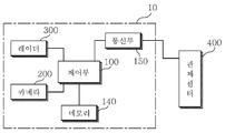
도 1은 본 발명의 일실시예에 따른 다차선 차량 속도 측정시스템(10)의 전체 구성도이고, 도 2는 도 1의 본 발명의 일실시예에 따른 다차선 차량 속도 측정 시스템(10)의 상세 블록도이고, 도 3은 도 2의 제어부(100)의 일 실시예를 나타내는 블록도이다.1 is an overall configuration diagram of a multi-lane vehicle
도 1을 참고하면, 본 발명의 일실시예에 따른 다차선 차량 속도 측정시스템(10)은 다차선 도로에 방사파를 출사하고, 다차선 도로를 주행하는 차량(20)으로부터 반사되는 반사파를 수신하기 위한 레이더(300), 상기 레이더(300)에 의해 감지되는 차량(20)을 촬영하여 영상을 획득하는 하나의 카메라(200), 그리고 상기 레이더(300)로부터의 제1 차량(20) 속도와 카메라(200)로부터의 제2 차량 속도를 연산하고 보정 및 비교하여 차량(20)의 최종 속도를 연산하는 제어부(100)를 포함한다.Referring to FIG. 1, a multi-lane vehicle
상기 레이더(300)는 짧은 주기를 가지고, 상기 방사파를 출사할 수 있으며, 상기 카메라(200)는 상기 레이더(300)로부터 수득된 방사파에 의해 과속 차량(20)이 타겟으로 인지되면, 트리거되어 다차선 중 타겟 차량(20)이 위치한 차선을 중심으로 2회 촬영을 진행한다. When the speeding
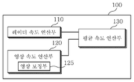
상기 제어부(100)는 레이더(300)로부터의 반사파를 수신하고, 이를 판독하여 차량(20)의 제1 차량 속도를 연산하는 레이더 속도 연산부(110), 상기 카메라(200)로부터 영상을 수신하고, 가공 및 보정하여 차량(20)의 제2 차량 속도를 연산하는 영상 속도 연산부(120), 그리고 제1 차량 속도와 제2 차량 속도를 수신하고, 이를 비교하여 최종 속도를 수득하는 최종 속도 연산부(130)를 포함한다.The
상세하게는, 상기 레이더 속도 연산부(110)는 레이더(300)로부터 방사파의 출사시점과 반사파의 수신시점 정보를 획득하여 레이더(300)로부터 차량(20)이 이격된 거리정보를 산출하여 거리정보로부터 속도 정보를 추출하여 제1 차량 속도로 정의하고, 상기 제1 차량 속도가 임계속도(단속속도)를 초과하는 경우 이를 과속 차량(20)으로 인지한다. 상기 과속 차량(20)이 타겟 차량(20)으로 정의되면, 이에 카메라(200)가 트리거되어 타겟 차량(20)이 포함된 풀프레임 영상을 2회에 걸쳐 촬영을 수행한다.The
또한, 상기 제어부(100)는 상기 타겟차량(20)의 상기 주행정보를 분석하여 상기 다차선 도로상의 풀프레임영상에서 상기 타겟차량(20)의 위치를 파악하고, 상기 다차선 도로상의 풀프레임영상에서 상기 차량이 위치한 영역을 크롭핑(cropping)하여 제1크롭핑영상으로 저장하고, 상기 제1 크롭핑영상으로부터 상기 타겟차량(20)의 번호판을 인식하여 상기 번호판이 위치한 영역을 크롭핑하여 제2 크롭핑영상으로 저장하는 영상처리부(도시하지 않음)를 더 포함할 수 있다.The
상기 영상처리부는 상기 2회에 걸친 영상으로부터 타겟 차량(20)이 위치하는 영역을 크롭(crop)하여 2 개의 제1 크롭핑 영상을 인식 영역(ROI: region of interest)을 획득한다. The image processing unit crops an area where the
상기 영상처리부는 상기 2개의 제1 크롭핑 영상 및 제1 크롭핑 영상으로부터 차량 번호판을 인식하고, 차량 번호판의 번호 및 위치를 판별한다. 이때, 상기 번호판 위치는 타겟 차량(20)의 번호판 내의 한 점을 기준점으로 정의할 수 있다. 일 예로 상기 기준점은 번호판의 중심일 수 있으며, 번호판이 직사각형인 경우, 4 개의 모서리 중 하나일 수 있다.The image processing unit recognizes the license plate from the two first cropping images and the first cropping image, and determines the number and position of the license plate. At this time, the license plate position can be defined as a reference point in the license plate of the
또한, 상기 제어부(100)는 상기 레이더속도연산부로부터 상기 레이더송수신수단에 의해 측정된 상기 타겟차량의 주행속도를 제1 차량속도로 정의하고, 상기 타겟 차량의 영상처리부에서 판별된 번호판의 위치를 전달받아 소정 시간 간격으로 촬영한 영상에서 이동된 차량번호의 픽셀 수를 계수하여 제2 차량속도로 정의할 때, 상기 제1 차량속도와 제2 차량속도와 일정시간 경과 후의 상기 제2 차량 속도 모두 임계 속도를 벗어나는 경우 단속대상차량으로 판단하는 단속판단부(도시하지 않음)를 더 포함할 수 있다.Further, the
또한, 상기 제2크롭핑영상에서 상기 차량 번호판의 번호를 인식하는 번호인식부(도시하지 않음)를 더 포함할 수 있다. In addition, a number recognition unit (not shown) for recognizing the number of the license plate in the second cropping image may be further included.
상기 영상 속도 연산부(120)는 상기 타겟차량(20)이 제1크롭핑영상 좌표계에서의 차지하는 제1좌표값을 풀프레임영상 좌표계에서 차지하는 제2좌표값으로 변환하고, 상기 제2좌표값의 시간에 따른 이동거리를 계산하여 차량의 속도를 연산한다.The
즉, 상기 영상 속도 연산부(120)는 전체 영상 내에서의 인식 영역의 위치에 대한좌표 보정을 수행하고, 기준점이 되는 번호판의 특징에 따라 보정하는 영상 보정부(125)를 포함할 수 있다. That is, the
상기 영상 속도 연산부(120)는 상기 영상 보정부(125)로부터의 보정된 제2 좌표값에 의해 제2 차량속도를 연산할 수 있다.The
상기 제2 차량 속도는 두 개의 영상 사이의 시간차에 대한 두 개의 보정된 제2 좌표값 사이의 거리를 기준으로 연산될 수 있다.The second vehicle speed may be calculated based on a distance between two corrected second coordinate values for a time difference between two images.
상기 최종 속도 연산부(130)는 상기 제1 차량 속도와 제2 차량 속도를 비교하여 두 개의 차량속도가 일치하는지, 레이더(300)에 의한 제1 차량 속도와 카메라(200)에 의한 제2 차량 속도가 오차 범위 내에 포함되는지를 판단하여 최종 속도를 산출한다. The
상기 제어부(100)는 산출된 최종 속도 및 차량 정보를 실시간으로 관제 센터(400)로 전송하기 위한 통신부(150)를 포함하며, 촬영된 영상, 차량번호, 평균속도, 날짜, 시간 데이터를 저장하는 메모리(140)를 포함한다.The
관제 센터(400)는 상기 다차선 차량(20) 속도 검출 시스템(10)으로부터의 과속 차량(20)에 대한 차량정보 및 최종속도 정보를 수신하고, 상기 차량(20) 영상 화면에 차량번호, 평균속도, 날짜 및 시간 데이터를 정해진 영역에 표출시키고 저장하는 서버를 포함한다.The
이하, 본 발명에 의한 다차선 차량(20) 속도 측정시스템(10)의 동작을 상세히 설명한다.Hereinafter, the operation of the
도 4는 제어부(100)의 속도 연산 방법을 나타내는 순서도이고, 도 5는 영상 속도 연산부(120)의 인식영역 획득하는 단계를 나타내는 그림이다.4 is a flowchart showing a speed calculation method of the
먼저, 레이더(300)가 주기적으로 반송파를 수신하고, 이를 연산하여 제1 차량 속도를 생성한다(s110). 레이더 속도 연산부(110)에서 연산된 차량(20)의 제1 차량 속도가 임계속도(단속속도)을 초과하는 것으로 판단되면(s120), 해당 차량(20)을 타겟 차량(20)으로 정의한다. 이때, 임계속도는 해당 다차선 도로의 단속속도일 수 있다. First, the
타겟 차량(20)이 정의되면, 타겟 차량(20)이 위치하는 차선을 인식하고(s130), 다차선 도로에 배치된 한대의 카메라(200)가 트리거되어 타겟 차량(20)이 포함되도록 시간차를 두고 2회에 걸쳐 촬영이 진행된다(s140).When the
일 예로, 2회에 걸쳐 활영된 2개의 영상은 도 5a 및 도 5b와 같이 80msec의 시간차를 두고 수득될 수 있다.For example, two images that are displayed twice can be obtained with a time difference of 80 msec as shown in Figs. 5A and 5B.
이때, 시간차는 제1 차량 속도에 따라 변동할 수 있으며, 60km/h 이하인 경우, 160msec 시간차를 가질 수 있고, 60km/h~80km/h인 경우, 120msec 의 시간차를 가질 수 있으며, 80km/h~100km/h인 경우, 80msec 의 시간차를 가질 수 있으며, 100km/h 이상인 경우, 40msec의 시간차를 가질 수 있다.In this case, the time difference may vary according to the first vehicle speed, and may have a time difference of 160 msec when the speed is 60 km / h or less, a time difference of 120 msec when the speed is 60 km / h to 80 km / In the case of 100 km / h, it may have a time difference of 80 msec. If it is 100 km / h or more, it may have a time difference of 40 msec.
영상 처리부는 2개의 영상으로부터 타겟 차량(20)의 차량 번호 정보를 수득하고, 타겟 차량(20)이 배치되어 있는 영역을 인식영역으로 크롭(crop)한다(s150). The image processing unit obtains vehicle number information of the
즉, 도 5a 및 도 5b와 같이, 붉은 선으로 정의되는 레이더(300) 거리 정보의 인식영역으로부터 타겟 차량(20) 위치를 정의하는 영역을 수득하고, 이를 포함하는 인식영역을 잘라내어 신호 처리 대상으로 정의한다. 5A and 5B, the area defining the position of the
이때, 인식 영역의 크기는 해당 타겟 차량(20) 위치를 정의하는 영역의 크기 및 영상 내 차량(20)의 크기에 따라 조절될 수 있다.At this time, the size of the recognition area can be adjusted according to the size of the area defining the position of the
도 5a 및 도 5b와 같이 시간차를 가지는 두 개의 영상에서 인식 영역의 위치가 차량(20)의 속도에 따라 이동한 것을 볼 수 있다.As shown in FIGS. 5A and 5B, it can be seen that the position of the recognition area is shifted according to the speed of the
상기 영상 속도 연산부(120)의 영상 보정부(125)는 상기 인식 영역의 전체 영상에서의 위치에 따라 수직 보정 및 수평 보정을 수행하고, 번호판과 관련하여 보정을 수행하고 기준점에 대한 보정된 좌표를 생성한다(s160).The
이때, 수직 및 수평 보정은 3차원의 공간이 2차원의 촬영 영상으로 전환되면서 원근감의 차이에 의해 발생하는 오차를 보정하는 것으로, 촬영 영상에서 픽셀 하나의 거리가 영상의 상부에 위치하는지 하부에 위치하는지에 따라 서로 다른 거리를 나타내게 되며, 이는 영상의 좌우의 차이에 의하여도 발생하게 된다.In this case, the vertical and horizontal corrections correct an error caused by a difference in perspective by converting a three-dimensional space into a two-dimensional photographed image, and determine whether a distance of one pixel in the photographed image is located at an upper portion , Which is caused by the difference of the left and right sides of the image.
따라서, 이러한 오차를 보상하여 수직 및 수평 보정을 진행함으로써 영상 전체가 아닌 인식 영역에 대하여만 데이터를 판독하여도 원근감으로부터의 오차 없이 정확한 좌표를 수득할 수 있다. Accordingly, by correcting such an error and performing vertical and horizontal correction, accurate coordinates can be obtained without error from the perspective by reading data only for the recognition area, not for the whole image.
상기 보정에 대하여는 뒤에 상세히 설명한다.The correction will be described later in detail.
영상 속도 연산부(120)는 보정된 좌표값을 기준으로 영상으로부터의 타겟 차량(20)의 제2 차량 속도를 연산한다(s170).The
다음으로, 최종속도 연산부(130)는 제1 차량 속도와 제2 차량 속도를 비교하여 최종속도를 연산한다(s180).Next, the final
최종속도 연산부(130)는 속도 편차를 연산하여 최종속도를 규정한다.The
속도 편차는 다음의 수식을 따른다.The velocity deviation is given by the following equation.
[수학식 1][Equation 1]
속도 편차=(제1 차량 속도/제2 차량 속도)??100Speed deviation = (first vehicle speed / second vehicle speed) ?? 100
최종속도연산부는 상기 제1 차량 속도와 상기 제2 차량 속도의 편차가 제1 임계값 미만이면 상기 제1 차량 속도를 상기 타겟차량의 속도로 정의하고, 상기 제1 차량 속도와 상기 제2 차량 속도의 편차가 제1임계값과 제2 임계값 사이의 범위를 충족하면 상기 제1 차량 속도와 상기 제2 차량 속도의 평균값을 상기 타겟차량의 속도로 정의하고, 상기 편차가 상기 제2 임계값을 초과하면 상기 타겟 차량의 속도를 버릴 수 있다.Wherein the final speed calculating section defines the first vehicle speed as the speed of the target vehicle when the deviation between the first vehicle speed and the second vehicle speed is less than the first threshold value and the first vehicle speed and the second vehicle speed Defines a mean value of the first vehicle speed and the second vehicle speed as a speed of the target vehicle if the deviation of the first vehicle speed and the second vehicle speed satisfies a range between the first threshold value and the second threshold value, The speed of the target vehicle can be discarded.
예컨데, 제1임계값이 3%, 제2임계값이 7%인 경우 제1차량속도와 제2차량속도의 편차가 3%보다 작으면, 타겟차량의 최종속도는 제1차량속도이고, 편차가 3% 내지 7%인 경우 타겟차량의 최종속도는 제1차량속도와 제2차량속도의 평균이고, 편차가 7%를 초과하는 경우 타겟차량의 최종속도를 연산하지 못하는 허수로 판단하고 에러로 처리한다.For example, when the first threshold value is 3% and the second threshold value is 7%, if the deviation between the first vehicle speed and the second vehicle speed is less than 3%, the final speed of the target vehicle is the first vehicle speed, Is 3% to 7%, the final speed of the target vehicle is an average of the first vehicle speed and the second vehicle speed, and when the deviation exceeds 7%, it is determined that the final speed of the target vehicle can not be calculated, .
마지막으로, 타겟 차량(20)에 대한 최종속도를 수득하면, 상기 타겟 차량(20)에 대한 정보, 즉, 차량 번호, 시간, 위치와 상기 최종속도를 관제 센터(400)에 실시간으로 전송하고 감지 동작을 종료한다.Finally, when the final speed for the
이와 같이 다차선에서의 차량(20)의 과속 여부를 하나의 레이더(300) 및 하나의 카메라(200)를 통해 수행하여 카메라(200)의 개수를 줄일 수 있고, 촬영된 영상에서 데이터 처리 대상인 인식 영역을 크롭하여 데이터 처리량을 줄이고, 처리 속도를 향상시킬 수 있다.As described above, the number of
한편, 본 발명의 다차선 차량 속도 측정 시스템(10)은 인식 영역을 크롭하여 데이터를 처리함에 있어 발생할 수 있는 오류에 대하여 보정을 수행하여 보다 신뢰성 있는 속도를 연산할 수 있다. Meanwhile, the multi-lane vehicle
이하에서는, 도 6 내지 도 8을 참고하여, 도 4의 인식 영역에 대한 좌표 보정을 상세히 설명한다.Hereinafter, coordinate correction for the recognition area of FIG. 4 will be described in detail with reference to FIGS. 6 to 8. FIG.
도 6은 도 4의 인식 영역에 대한 보정을 나타내는 순서도이고, 도 7은 도 6의 좌표 수득을 나타내는 그림이며, 도 8은 도 6의 역 차량기준좌표 수득을 나타내는 그림이다.FIG. 6 is a flowchart showing correction for the recognition area in FIG. 4, FIG. 7 is a diagram showing the coordinate acquisition in FIG. 6, and FIG. 8 is a diagram showing the inverse vehicle reference coordinate acquisition in FIG.
도 6을 참고하면, 풀프레임영상에서의 좌표계 및 제1크롭핑영역에서의 좌표계가 각각 정의된 상태에서, 영상 보정부(125)는 풀프레임영상 좌표계에서 제1크롭핑영역이 해당하는 영역의 좌표값을 수득한다(s161).6, in a state where the coordinate system in the full frame image and the coordinate system in the first cropping area are respectively defined, the
제1크롭핑영역의 풀프레임영상 좌표계에서의 좌표값은 풀프레임영상에서 제1크롭핑영역이 어디에 위치하는지에 따라 발생하는 거리 오차를 보정하기 위한 기초 데이터가 된다.The coordinate values in the full-frame image coordinate system of the first cropping area become basic data for correcting the distance error generated depending on where the first cropping area is located in the full-frame image.
다음으로, 제1크롭핑영역 좌표계에서 상기 타겟 차량(20)의 차량기준좌표값를 수득한다(s163). Next, the vehicle reference coordinate value of the
이러한 차량기준좌표값은 번호판의 좌표값일 수 있으며, 번호판의 한 점 또는 복수의 점일 수 있다. 일예로, 도 7과 같이, 좌측 상단 모서리와 우측 하단 모서리의 좌표값을 차량기준좌표로 인식할 수 있다. Such a vehicle reference coordinate value may be a coordinate value of the license plate, and may be a point or a plurality of points of the license plate. For example, as shown in FIG. 7, coordinate values of the upper left corner and the lower right corner can be recognized as vehicle reference coordinates.
다음으로, 제1크롭핑영상을 풀프레임영상 내로 변환을 수행하면, 도 8과 같이 시간차를 두고 촬영된 두 개의 제1크롭핑영상(t1) 및 제1크롭핑영상(t2)의 좌우 상단의 배치가 이동한다(s165). Next, when the first cropping image is transformed into the full-frame image, the two first cropping images t1 and the first cropping images t2 captured at time intervals as shown in Fig. The arrangement moves (s165).
다음으로, 제1크롭핑영역에서의 차량기준좌표값을 풀프레임영상 좌표계의 좌표값으로 변환하여 수득한다(s167). Next, the vehicle reference coordinate value in the first cropping area is converted into the coordinate value of the full frame image coordinate system and obtained (s167).
이로써, 도 7 및 도 8과 같이 시간차를 가지는 두 개의 영상으로부터의 두 개의 제1크롭핑영상에서의 우측 하단 모서리의 y축좌표값 차가 74 픽셀에서 풀프레임영상 좌표계에 의한 우측 하단 모서리의 y축좌표 차는 124픽셀이 된다.As a result, the difference between the y-axis coordinate values of the lower right corner of the two first cropping images from the two images having time differences as shown in Figs. 7 and 8 is set to 74 pixels, which is the y- The coordinate difference becomes 124 pixels.
즉, 인식 영역의 좌표를 반영하여 데이터 처리를 인식 영역만을 수행하여 연산 속도를 높이면서도 데이터의 정확성을 확보할 수 있다.In other words, the accuracy of the data can be secured while increasing the operation speed by performing the data processing only on the recognition area by reflecting the coordinates of the recognition area.
다음으로, 풀프레임영상 좌표계에 수직 보정 및 수평 보정을 수행한다(s168).Next, vertical correction and horizontal correction are performed on the full-frame image coordinate system (s168).
상기 수직 보정 및 수평 보정은 상기 좌표값이 풀프레임영상의 어느 영역에 위치하는지에 따라 가중치를 두어 2차원 영상으로부터 3차원 실제 차량(20)의 이동 거리를 보정하여 이루어진다. The vertical correction and the horizontal correction are performed by correcting the moving distance of the three-dimensional
즉, 3차원 공간이 2차원 촬영 연상으로 전환되면서 원근감의 차이에 발생하는 오차를 보정하는 것으로, 영상에서 하나의 픽셀은 동일한 거리 값을 가지나, 상기 픽셀이 2차원 영상에서 위 또는 아래 중 어느 위치에 배치되는지에 따라 해당 픽셀이 가지는 거리 값이 상이하고, 좌 또는 우 중 어느 위치에 배치되는지에 따라 거리 값이 상이하다. That is, by correcting an error occurring in a difference of perspective by converting a three-dimensional space into a two-dimensional imaging association, one pixel in the image has the same distance value, but when the pixel is located at any position The distance value of the corresponding pixel is different and the distance value is different depending on which of the left and right positions is located.
따라서, 각 픽셀의 위치에 따라 가중치를 두고, 해당 기준치를 곱하여 보정된 풀프레임 좌표값으로부터 차량(20)의 이동 거리를 연산할 수 있다. Accordingly, the movement distance of the
이때, 상기 영상 보정부(125)는 역차량기준좌표에 수직 및 수평 보정을 수행한 뒤, 번호판 보정을 더 진행할 수 있다(s169).At this time, the
도 9는 도 6의 번호판 보정을 나타내는 상세 순서도이고, 도 10은 도 9의 번호판 특징 추출하는 동작을 나타내는 그림이고, 도 11은 도 9의 차종분석을 나타내는 그림이며, 도 12는 도 9의 번호판 높이 측정을 나타내는 그림이다.Fig. 9 is a detailed flowchart showing the license plate correction of Fig. 6, Fig. 10 is a drawing showing an operation of extracting the license plate feature of Fig. 9, Fig. 11 is a diagram showing vehicle type analysis of Fig. 9, FIG.
도 9를 참고하면, 번호판 보정이 시작되면, 상기 영상 보정부(125)는 두 개의 촬영 영상으로부터 타겟 차량(20)의 번호판의 특징을 추출한다(s200).Referring to FIG. 9, when the license plate correction is started, the
이때, 번호판 특징으로는 번호판의 크기, 색깔, 가로세로비율 등일 수 있다.At this time, the license plate feature may be the size, color, aspect ratio, etc. of the license plate.
다음으로, 두 개의 촬영 영상으로부터 타겟 차량(20)의 차종 분석을 수행한다(s210). 상기 차종 분석은 차량(20)의 크기에 따라 대형, 중형, 소형 차량(20)으로 분류하고, 세부 차종분류를 수행한다.Next, the analysis of the model of the
즉, 차량(20)을 승용차, 버스, 트럭, 기타 차량(20)으로 분류하고, 버스인 경우 속도 보정을 수행하지 않고, 다른 차종인 경우에만 속도 보정을 수행할 수 있다.That is, it is possible to classify the
다음으로, 번호판 높이(d)를 측정한다(s220).Next, the license plate height d is measured (s220).
상기 번호판 높이(d)는 차량(20)의 하단, 즉, 차량(20)의 타이어 밑단으로부터 번호판의 기준점, 일예로 번호판의 우측 하단 모서리까지의 최단거리로 정의할 수 있으며, 도 11a 내지 도 11d와 같이 차종에 따라 서로 다른 높이를 가질 수 있고, 도 12a 및 도 12b와 같이 같은 차종에서도 차량(20) 내 번호판이 배치된 영역에 따라 서로 다를 수 있다.The plate height d can be defined as the shortest distance from the lower end of the
이와 같이 번호판의 위치 분석이 종료되면, 차량(20) 헤드라이트 위치 분석을 수행한다(s230).When the analysis of the position of the license plate is finished, the headlight position analysis of the
상기 헤드라이트 분석은 헤드라이트 사이의 간격으로 차량(20)의 폭을 추정하여 대형 차량(20)을 구분할 수 있으며, 차량(20) 헤드라이트로부터의 번호판의 기준점 위치를 분석할 수 있다.The headlight analysis can distinguish the
다음으로, 기 수행된 번호판 특징, 차종, 번호판 높이, 헤드 라이트 분석 내용을 바탕으로 번호판 좌표 보정을 수행한다(s240).Next, the license plate coordinate correction is performed based on the license plate characteristics, vehicle type, license plate height, and headlight analysis contents (s240).
즉, 도 10의 번호판 a와 번호판 b를 검토하면, 차량(20)이 근접함에 따라 번호판의 크기가 5 ~15% 확대되어 보일 수 있다. 따라서, 확대 비율에 대한 가중치를 두어 픽셀의 좌표 보정을 수행할 수 있으며, 이때 좌표는 기준점, 일 예로 번호판의 모서리 또는 중심일 수 있다.That is, when the license plate a and the license plate b in FIG. 10 are examined, the size of the license plate can be enlarged by 5 to 15% as the
또한, 도 11 및 도 12와 같이 차종 및 번호판의 배치에 따라 지면으로부터 번호판의 높이(d)가 달라질 수 있어 앞서 설명한 수직 오차를 발생하게 된다. Also, as shown in FIGS. 11 and 12, the height d of the license plate can be changed from the ground according to the arrangement of the vehicle model and the license plate, thereby generating the vertical error described above.
따라서, 차종 및 번호판의 높이(d)에 따라 가중치를 두어 오차를 보상하는 기준점의 좌표를 생성할 수 있다. 이때, 상기 가중치는 상기 번호판의 높이(d)가 임계값 이상인 경우에만 부여될 수 있다. Therefore, weights can be given according to the height d of the vehicle model and the license plate to generate the coordinates of the reference point that compensates for the error. At this time, the weight can be given only when the height (d) of the plate is greater than or equal to a threshold value.
이와 같이 번호판 보정을 수행한 보정된 기준점의 좌표로부터 차량(20)의 속도를 연산하여 신뢰도가 향상된 데이터를 구할 수 있다.The speed of the
이상, 첨부한 도면을 참조하여 본 발명의 바람직한 실시예에 대하여 상세히 설명하였으나 이는 예시에 불과한 것이다.Although the preferred embodiments of the present invention have been described in detail with reference to the accompanying drawings, the present invention is by way of example only.
해당 기술 분야의 숙련된 당업자는 하기의 특허청구범위에 기재된 본 발명의 사상 및 영역으로부터 벗어나지 않는 범위 내에서 본 발명을 다양하게 수정 및 변경시킬 수 있음을 이해할 수 있을 것이다.It will be understood by those skilled in the art that various changes in form and details may be made therein without departing from the spirit and scope of the invention as defined in the appended claims.
Claims (9)
상기 타겟차량의 상기 주행정보를 분석하여 상기 다차선 도로상의 풀프레임영상에서 상기 타겟차량의 위치를 파악하고, 상기 다차선 도로상의 풀프레임영상에서 상기 차량이 위치한 영역을 크롭핑(cropping)하여 제1 크롭핑영상으로 저장하고, 상기 제1 크롭핑영상으로부터 상기 타겟차량의 번호판을 인식하여 상기 번호판이 위치한 영역을 크롭핑하여 제2 크롭핑영상으로 저장하는 영상처리부, 그리고
상기 영상처리부로부터 소정의 시간간격으로 촬영된 영상들을 전달받아 상기 타겟 차량이 제1 크롭핑영상 좌표계에서의 차지하는 제1 좌표값을 풀프레임영상 좌표계에서 차지하는 제2 좌표값으로 변환하고, 상기 제2 좌표값의 시간에 따른 이동거리를 계산하여 차량의 속도를 연산하는 영상속도연산부를 포함하는 제어부
를 포함하는 다차선 차량 속도 측정 시스템.A multi-lane road, and a full-frame image including the target vehicle,
The method comprising the steps of: analyzing the driving information of the target vehicle to grasp the position of the target vehicle in the full-frame image on the multi-lane road; cropping the area where the vehicle is located in the full- 1 cropping image, recognizes the license plate of the target vehicle from the first cropping image, and crops an area where the license plate is located to store the license key as a second cropping image, and
A first coordinate value occupied by the target vehicle in the first cropping image coordinate system is converted into a second coordinate value occupied in the full frame image coordinate system by receiving the images photographed at a predetermined time interval from the image processing unit, A control unit including a video speed calculating unit for calculating a moving speed of the vehicle by calculating a moving distance of the coordinate value with respect to time;
And a multi-lane vehicle speed measurement system.
상기 영상 속도 연산부는,
상기 시간차를 두고 2회에 걸쳐 촬영된 영상들로부터 크롭핑된 상기 제1 크롭핑 영상들로부터 각각의 차량 번호판의 위치를 판별하며, 상기 번호판 위치를 기준으로 상기 차량 속도를 연산하는 다차선 차량 속도 측정 시스템.The method according to claim 1,
Wherein the image-
Wherein the control unit determines the position of each license plate from the first cropping images cropped from the images photographed twice over the time difference, and calculates the multi-lane vehicle speed Measuring system.
상기 영상 속도 연산부는
상기 제2 좌표값에 수직 보정 및 수평 보정을 포함하는 보상을 수행하는 영상 보정부
를 포함하는 다차선 차량 속도 측정 시스템.3. The method of claim 2,
The image-
And an image correction unit for performing compensation including the vertical correction and the horizontal correction on the second coordinate value,
And a multi-lane vehicle speed measurement system.
상기 보상은 상기 제2좌표값의 상기 풀프레임 내에서 차지하는 위치에 따라 픽셀의 가중치를 곱하여 이루어지는 다차선 차량 속도 측정 시스템.The method of claim 3,
Wherein the compensation is performed by multiplying a weight of the pixel by a position occupied within the full frame of the second coordinate value.
상기 영상 보정부는
상기 제2 좌표값을 포함하는 상기 번호판에 대한 오차를 보상하는 번호판 보상을 진행하며,
상기 번호판 보상은 번호판의 특성 및 차종을 판단하여 진행되는 다차선 차량 속도 측정 시스템. 5. The method of claim 4,
The image correction unit
A license plate compensation process for compensating an error of the license plate including the second coordinate value,
Wherein the number plate compensation is performed by determining characteristics of a license plate and a vehicle type.
상기 번호판의 특성은 번호판의 크기, 가로세로비율, 색깔 및 번호판의 타이어 밑단으로부터의 높이를 포함하는 다차선 차량 속도 측정 시스템.6. The method of claim 5,
The characteristics of the license plate include the size of the license plate, the aspect ratio, the color, and the height of the license plate from the tire bottom.
상기 차종은 헤드라이트 사이의 간격에 따른 차량의 폭의 계산으로 판단하는 다차선 차량 속도 측정 시스템.6. The method of claim 5,
Wherein said vehicle type is determined by calculation of a width of a vehicle in accordance with an interval between headlights.
다차선 도로에 방사파를 출사하고, 다차선 도로를 주행하는 차량으로부터 반사되는 반사파를 수신하는 레이더, 그리고
상기 레이더로부터의 반사파를 수신하고, 이를 판독하여 상기 차량 속도를 연산하는 레이더 속도 연산부를 더 포함하는 다차선 차량 속도 측정 시스템.The method according to claim 1,
A radar that emits a radio wave on a multi-lane road, receives a reflected wave reflected from a vehicle traveling on a multi-lane road, and
Further comprising a radar velocity calculation unit for receiving the reflected wave from the radar and reading it to calculate the vehicle velocity.
상기 타겟차량의 상기 주행정보를 분석하여 상기 다차선 도로상의 풀프레임영상에서 상기 타겟차량의 위치를 파악하고, 상기 다차선 도로상의 풀프레임영상에서 상기 차량이 위치한 영역을 크롭핑(cropping)하여 제1 크롭핑영상으로 저장하고, 상기 제1 크롭핑영상으로부터 상기 타겟차량의 번호판을 인식하여 상기 번호판이 위치한 영역을 크롭핑하여 제2 크롭핑영상으로 저장단계, 그리고
소정의 시간간격으로 촬영된 영상들을 전달받아 상기 타겟 차량이 제1 크롭핑영상 좌표계에서의 차지하는 제1 좌표값을 풀프레임영상 좌표계에서 차지하는 제2 좌표값으로 변환하고, 상기 제2 좌표값의 시간에 따른 이동거리를 계산하여 차량의 속도를 연산하는 단계
를 포함하는 다차선 차량 속도 측정 방법.
Taking a multi-lane road and a full-frame image including the target vehicle,
The method comprising the steps of: analyzing the driving information of the target vehicle to grasp the position of the target vehicle in the full-frame image on the multi-lane road; cropping the area where the vehicle is located in the full- 1 cropping image, recognizing the license plate of the target vehicle from the first cropping image, cropping the area where the license plate is located, and storing it as a second cropping image, and
A first coordinate value occupied by the target vehicle in the first cropping image coordinate system is converted into a second coordinate value occupied in the full frame image coordinate system by receiving the images photographed at predetermined time intervals and the time of the second coordinate value Calculating a moving distance according to the vehicle speed
Of the vehicle speed.
Applications Claiming Priority (2)
| Application Number | Priority Date | Filing Date | Title |
|---|---|---|---|
| KR1020150190076 | 2015-12-30 | ||
| KR20150190076 | 2015-12-30 |
Publications (2)
| Publication Number | Publication Date |
|---|---|
| KR20170080481A true KR20170080481A (en) | 2017-07-10 |
| KR101898051B1 KR101898051B1 (en) | 2018-09-12 |
Family
ID=59356112
Family Applications (1)
| Application Number | Title | Priority Date | Filing Date |
|---|---|---|---|
| KR1020160173721A KR101898051B1 (en) | 2015-12-30 | 2016-12-19 | Multilane vehicle speed detecting system |
Country Status (1)
| Country | Link |
|---|---|
| KR (1) | KR101898051B1 (en) |
Cited By (7)
| Publication number | Priority date | Publication date | Assignee | Title |
|---|---|---|---|---|
| KR102052833B1 (en) | 2018-07-17 | 2019-12-09 | 김항섭 | Apparatus and method for vehicle speed detection using image tracking |
| KR102100965B1 (en) * | 2019-05-27 | 2020-04-14 | 주식회사 엔슨소프트 | System for analyzing vehicle information on multi-lane embedded a camera and analyzing method using thereof |
| KR102161516B1 (en) * | 2020-04-27 | 2020-10-05 | 주식회사 펜타게이트 | Classification of vehicles using deep learning-based data expansion learning |
| KR20220009608A (en) | 2020-07-16 | 2022-01-25 | 주식회사 비젼그리드 | Method and apparatus for generating virtual curved grid lines for vehicle speed detection using image tracking |
| KR20220042623A (en) * | 2020-09-28 | 2022-04-05 | 인하대학교 산학협력단 | Image based speed control system using deep learning |
| KR102459996B1 (en) * | 2021-12-02 | 2022-10-28 | 주식회사 케이티앤씨 | Automatic calibration device and method for vehicle speed measurement |
| KR102477410B1 (en) * | 2022-09-08 | 2022-12-15 | 주식회사 아프로시스템즈 | Traffic violation enforcement system using rear license plate recognition and method for rear license plate recognition |
Families Citing this family (1)
| Publication number | Priority date | Publication date | Assignee | Title |
|---|---|---|---|---|
| KR102238401B1 (en) * | 2020-09-14 | 2021-04-09 | 전주비전대학교산학협력단 | Recognition Method of License Plate Number Using Data expansion and CNN |
Citations (4)
| Publication number | Priority date | Publication date | Assignee | Title |
|---|---|---|---|---|
| JPH0883393A (en) * | 1994-09-14 | 1996-03-26 | Hitachi Ltd | Vehicle speed measuring instrument |
| JP2000241440A (en) * | 1999-02-19 | 2000-09-08 | Fujitsu Ltd | Speed measuring method for automobile and its device |
| KR100884583B1 (en) * | 2007-08-28 | 2009-02-19 | 경북대학교 산학협력단 | Speed detection system and method |
| KR101291301B1 (en) * | 2013-02-28 | 2013-07-30 | 심광호 | Vehicle speed measurement system using image and radar |
-
2016
- 2016-12-19 KR KR1020160173721A patent/KR101898051B1/en active IP Right Grant
Patent Citations (4)
| Publication number | Priority date | Publication date | Assignee | Title |
|---|---|---|---|---|
| JPH0883393A (en) * | 1994-09-14 | 1996-03-26 | Hitachi Ltd | Vehicle speed measuring instrument |
| JP2000241440A (en) * | 1999-02-19 | 2000-09-08 | Fujitsu Ltd | Speed measuring method for automobile and its device |
| KR100884583B1 (en) * | 2007-08-28 | 2009-02-19 | 경북대학교 산학협력단 | Speed detection system and method |
| KR101291301B1 (en) * | 2013-02-28 | 2013-07-30 | 심광호 | Vehicle speed measurement system using image and radar |
Cited By (7)
| Publication number | Priority date | Publication date | Assignee | Title |
|---|---|---|---|---|
| KR102052833B1 (en) | 2018-07-17 | 2019-12-09 | 김항섭 | Apparatus and method for vehicle speed detection using image tracking |
| KR102100965B1 (en) * | 2019-05-27 | 2020-04-14 | 주식회사 엔슨소프트 | System for analyzing vehicle information on multi-lane embedded a camera and analyzing method using thereof |
| KR102161516B1 (en) * | 2020-04-27 | 2020-10-05 | 주식회사 펜타게이트 | Classification of vehicles using deep learning-based data expansion learning |
| KR20220009608A (en) | 2020-07-16 | 2022-01-25 | 주식회사 비젼그리드 | Method and apparatus for generating virtual curved grid lines for vehicle speed detection using image tracking |
| KR20220042623A (en) * | 2020-09-28 | 2022-04-05 | 인하대학교 산학협력단 | Image based speed control system using deep learning |
| KR102459996B1 (en) * | 2021-12-02 | 2022-10-28 | 주식회사 케이티앤씨 | Automatic calibration device and method for vehicle speed measurement |
| KR102477410B1 (en) * | 2022-09-08 | 2022-12-15 | 주식회사 아프로시스템즈 | Traffic violation enforcement system using rear license plate recognition and method for rear license plate recognition |
Also Published As
| Publication number | Publication date |
|---|---|
| KR101898051B1 (en) | 2018-09-12 |
Similar Documents
| Publication | Publication Date | Title |
|---|---|---|
| KR101925293B1 (en) | The vehicle detecting system by converging radar and image | |
| KR101898051B1 (en) | Multilane vehicle speed detecting system | |
| US11348266B2 (en) | Estimating distance to an object using a sequence of images recorded by a monocular camera | |
| CN107272021B (en) | Object detection using radar and visually defined image detection areas | |
| CN110609274B (en) | Distance measurement method, device and system | |
| KR101411668B1 (en) | A calibration apparatus, a distance measurement system, a calibration method, and a computer readable medium recording a calibration program | |
| US8378851B2 (en) | Fusion of images in enhanced obstacle detection | |
| US8964031B2 (en) | Method and system for measuring the speed of a vehicle | |
| US10015394B2 (en) | Camera-based speed estimation and system calibration therefor | |
| EP2639781A1 (en) | Vehicle with improved traffic-object position detection | |
| US20050232463A1 (en) | Method and apparatus for detecting a presence prior to collision | |
| US20050270286A1 (en) | Method and apparatus for classifying an object | |
| JPH07320199A (en) | Obstacle detector for vehicle | |
| WO2017116134A1 (en) | Radar and image-fusion vehicle enforcement system | |
| CN103559791A (en) | Vehicle detection method fusing radar and CCD camera signals | |
| JP3727400B2 (en) | Crossing detection device | |
| CN102806913A (en) | Novel lane line deviation detection method and device | |
| KR101735557B1 (en) | System and Method for Collecting Traffic Information Using Real time Object Detection | |
| KR102062579B1 (en) | Vehicle license-plate recognition system that recognition of Vehicle license-plate damaged by shadow and light reflection through the correction | |
| JP7312275B2 (en) | Information processing device, sensing device, moving object, information processing method, and information processing system | |
| CN110659551A (en) | Motion state identification method and device and vehicle | |
| KR20070070671A (en) | Velocity measuring apparatus and method using optical flow | |
| KR101890482B1 (en) | Appartus for distinction of stop and movement using radar spectrum and method thereof | |
| US20220309776A1 (en) | Method and system for determining ground level using an artificial neural network | |
| US20230001923A1 (en) | Vehicular automatic emergency braking system with cross-path threat determination |
Legal Events
| Date | Code | Title | Description |
|---|---|---|---|
| A201 | Request for examination | ||
| A302 | Request for accelerated examination | ||
| E902 | Notification of reason for refusal | ||
| E701 | Decision to grant or registration of patent right | ||
| GRNT | Written decision to grant |