KR20170078791A - Production of a spinel material - Google Patents
Production of a spinel material Download PDFInfo
- Publication number
- KR20170078791A KR20170078791A KR1020177014766A KR20177014766A KR20170078791A KR 20170078791 A KR20170078791 A KR 20170078791A KR 1020177014766 A KR1020177014766 A KR 1020177014766A KR 20177014766 A KR20177014766 A KR 20177014766A KR 20170078791 A KR20170078791 A KR 20170078791A
- Authority
- KR
- South Korea
- Prior art keywords
- lmo
- lithium
- cathode
- manganese
- lmoa
- Prior art date
Links
Images


Classifications
-
- C—CHEMISTRY; METALLURGY
- C01—INORGANIC CHEMISTRY
- C01G—COMPOUNDS CONTAINING METALS NOT COVERED BY SUBCLASSES C01D OR C01F
- C01G45/00—Compounds of manganese
- C01G45/12—Manganates manganites or permanganates
- C01G45/1221—Manganates or manganites with a manganese oxidation state of Mn(III), Mn(IV) or mixtures thereof
- C01G45/1242—Manganates or manganites with a manganese oxidation state of Mn(III), Mn(IV) or mixtures thereof of the type [Mn2O4]-, e.g. LiMn2O4, Li[MxMn2-x]O4
-
- H—ELECTRICITY
- H01—ELECTRIC ELEMENTS
- H01M—PROCESSES OR MEANS, e.g. BATTERIES, FOR THE DIRECT CONVERSION OF CHEMICAL ENERGY INTO ELECTRICAL ENERGY
- H01M10/00—Secondary cells; Manufacture thereof
- H01M10/05—Accumulators with non-aqueous electrolyte
- H01M10/052—Li-accumulators
-
- H—ELECTRICITY
- H01—ELECTRIC ELEMENTS
- H01M—PROCESSES OR MEANS, e.g. BATTERIES, FOR THE DIRECT CONVERSION OF CHEMICAL ENERGY INTO ELECTRICAL ENERGY
- H01M10/00—Secondary cells; Manufacture thereof
- H01M10/05—Accumulators with non-aqueous electrolyte
- H01M10/052—Li-accumulators
- H01M10/0525—Rocking-chair batteries, i.e. batteries with lithium insertion or intercalation in both electrodes; Lithium-ion batteries
-
- H—ELECTRICITY
- H01—ELECTRIC ELEMENTS
- H01M—PROCESSES OR MEANS, e.g. BATTERIES, FOR THE DIRECT CONVERSION OF CHEMICAL ENERGY INTO ELECTRICAL ENERGY
- H01M10/00—Secondary cells; Manufacture thereof
- H01M10/05—Accumulators with non-aqueous electrolyte
- H01M10/058—Construction or manufacture
-
- H—ELECTRICITY
- H01—ELECTRIC ELEMENTS
- H01M—PROCESSES OR MEANS, e.g. BATTERIES, FOR THE DIRECT CONVERSION OF CHEMICAL ENERGY INTO ELECTRICAL ENERGY
- H01M4/00—Electrodes
- H01M4/02—Electrodes composed of, or comprising, active material
- H01M4/36—Selection of substances as active materials, active masses, active liquids
- H01M4/48—Selection of substances as active materials, active masses, active liquids of inorganic oxides or hydroxides
- H01M4/50—Selection of substances as active materials, active masses, active liquids of inorganic oxides or hydroxides of manganese
- H01M4/505—Selection of substances as active materials, active masses, active liquids of inorganic oxides or hydroxides of manganese of mixed oxides or hydroxides containing manganese for inserting or intercalating light metals, e.g. LiMn2O4 or LiMn2OxFy
-
- C—CHEMISTRY; METALLURGY
- C01—INORGANIC CHEMISTRY
- C01P—INDEXING SCHEME RELATING TO STRUCTURAL AND PHYSICAL ASPECTS OF SOLID INORGANIC COMPOUNDS
- C01P2002/00—Crystal-structural characteristics
- C01P2002/30—Three-dimensional structures
- C01P2002/32—Three-dimensional structures spinel-type (AB2O4)
-
- C—CHEMISTRY; METALLURGY
- C01—INORGANIC CHEMISTRY
- C01P—INDEXING SCHEME RELATING TO STRUCTURAL AND PHYSICAL ASPECTS OF SOLID INORGANIC COMPOUNDS
- C01P2002/00—Crystal-structural characteristics
- C01P2002/50—Solid solutions
- C01P2002/52—Solid solutions containing elements as dopants
- C01P2002/54—Solid solutions containing elements as dopants one element only
-
- C—CHEMISTRY; METALLURGY
- C01—INORGANIC CHEMISTRY
- C01P—INDEXING SCHEME RELATING TO STRUCTURAL AND PHYSICAL ASPECTS OF SOLID INORGANIC COMPOUNDS
- C01P2002/00—Crystal-structural characteristics
- C01P2002/70—Crystal-structural characteristics defined by measured X-ray, neutron or electron diffraction data
- C01P2002/72—Crystal-structural characteristics defined by measured X-ray, neutron or electron diffraction data by d-values or two theta-values, e.g. as X-ray diagram
-
- C—CHEMISTRY; METALLURGY
- C01—INORGANIC CHEMISTRY
- C01P—INDEXING SCHEME RELATING TO STRUCTURAL AND PHYSICAL ASPECTS OF SOLID INORGANIC COMPOUNDS
- C01P2002/00—Crystal-structural characteristics
- C01P2002/80—Crystal-structural characteristics defined by measured data other than those specified in group C01P2002/70
- C01P2002/82—Crystal-structural characteristics defined by measured data other than those specified in group C01P2002/70 by IR- or Raman-data
-
- C—CHEMISTRY; METALLURGY
- C01—INORGANIC CHEMISTRY
- C01P—INDEXING SCHEME RELATING TO STRUCTURAL AND PHYSICAL ASPECTS OF SOLID INORGANIC COMPOUNDS
- C01P2002/00—Crystal-structural characteristics
- C01P2002/80—Crystal-structural characteristics defined by measured data other than those specified in group C01P2002/70
- C01P2002/85—Crystal-structural characteristics defined by measured data other than those specified in group C01P2002/70 by XPS, EDX or EDAX data
-
- C—CHEMISTRY; METALLURGY
- C01—INORGANIC CHEMISTRY
- C01P—INDEXING SCHEME RELATING TO STRUCTURAL AND PHYSICAL ASPECTS OF SOLID INORGANIC COMPOUNDS
- C01P2004/00—Particle morphology
- C01P2004/01—Particle morphology depicted by an image
- C01P2004/03—Particle morphology depicted by an image obtained by SEM
-
- C—CHEMISTRY; METALLURGY
- C01—INORGANIC CHEMISTRY
- C01P—INDEXING SCHEME RELATING TO STRUCTURAL AND PHYSICAL ASPECTS OF SOLID INORGANIC COMPOUNDS
- C01P2004/00—Particle morphology
- C01P2004/01—Particle morphology depicted by an image
- C01P2004/04—Particle morphology depicted by an image obtained by TEM, STEM, STM or AFM
-
- C—CHEMISTRY; METALLURGY
- C01—INORGANIC CHEMISTRY
- C01P—INDEXING SCHEME RELATING TO STRUCTURAL AND PHYSICAL ASPECTS OF SOLID INORGANIC COMPOUNDS
- C01P2006/00—Physical properties of inorganic compounds
- C01P2006/40—Electric properties
-
- H—ELECTRICITY
- H01—ELECTRIC ELEMENTS
- H01M—PROCESSES OR MEANS, e.g. BATTERIES, FOR THE DIRECT CONVERSION OF CHEMICAL ENERGY INTO ELECTRICAL ENERGY
- H01M4/00—Electrodes
- H01M4/02—Electrodes composed of, or comprising, active material
- H01M2004/026—Electrodes composed of, or comprising, active material characterised by the polarity
- H01M2004/028—Positive electrodes
-
- Y—GENERAL TAGGING OF NEW TECHNOLOGICAL DEVELOPMENTS; GENERAL TAGGING OF CROSS-SECTIONAL TECHNOLOGIES SPANNING OVER SEVERAL SECTIONS OF THE IPC; TECHNICAL SUBJECTS COVERED BY FORMER USPC CROSS-REFERENCE ART COLLECTIONS [XRACs] AND DIGESTS
- Y02—TECHNOLOGIES OR APPLICATIONS FOR MITIGATION OR ADAPTATION AGAINST CLIMATE CHANGE
- Y02E—REDUCTION OF GREENHOUSE GAS [GHG] EMISSIONS, RELATED TO ENERGY GENERATION, TRANSMISSION OR DISTRIBUTION
- Y02E60/00—Enabling technologies; Technologies with a potential or indirect contribution to GHG emissions mitigation
- Y02E60/10—Energy storage using batteries
-
- Y—GENERAL TAGGING OF NEW TECHNOLOGICAL DEVELOPMENTS; GENERAL TAGGING OF CROSS-SECTIONAL TECHNOLOGIES SPANNING OVER SEVERAL SECTIONS OF THE IPC; TECHNICAL SUBJECTS COVERED BY FORMER USPC CROSS-REFERENCE ART COLLECTIONS [XRACs] AND DIGESTS
- Y02—TECHNOLOGIES OR APPLICATIONS FOR MITIGATION OR ADAPTATION AGAINST CLIMATE CHANGE
- Y02P—CLIMATE CHANGE MITIGATION TECHNOLOGIES IN THE PRODUCTION OR PROCESSING OF GOODS
- Y02P70/00—Climate change mitigation technologies in the production process for final industrial or consumer products
- Y02P70/50—Manufacturing or production processes characterised by the final manufactured product
Landscapes
- Chemical & Material Sciences (AREA)
- Chemical Kinetics & Catalysis (AREA)
- Electrochemistry (AREA)
- General Chemical & Material Sciences (AREA)
- Inorganic Chemistry (AREA)
- Organic Chemistry (AREA)
- Engineering & Computer Science (AREA)
- Manufacturing & Machinery (AREA)
- Materials Engineering (AREA)
- Battery Electrode And Active Subsutance (AREA)
- Inorganic Compounds Of Heavy Metals (AREA)
- Secondary Cells (AREA)
Abstract
리튬-망간 옥사이드 스피넬 재료의 제조 방법으로서, 상기 제조 방법이 연소 합성에 의해 비가공된 리튬-망간 옥사이드('LMO') 재료를 제조하는 단계; 선택적으로, 상기 비가공된 LMO 재료에 마이크로웨이브 처리를 가하여 처리된 재료를 얻는 단계; 상기 비가공된 LMO 재료 또는 상기 처리된 재료를 어닐링하여 어닐링된 재료를 얻는 단계; 및 선택적으로, 상기 어닐링된 재료에 마이크로웨이브 처리를 가하는 단계;를 포함한다. 1회 이상의 마이크로웨이브 처리가 이루어져야 한다.A process for the production of a lithium-manganese oxide spinel material, said process comprising the steps of: preparing a lithium-manganese oxide ('LMO') material that has been processed by combustion synthesis; Optionally, microwave treatment is applied to the unprocessed LMO material to obtain a treated material; Annealing the unprocessed LMO material or the treated material to obtain an annealed material; And, optionally, applying microwave treatment to the annealed material. At least one microwave treatment should be performed.
Description
본 발명은 스피넬 재료의 제조에 관한 것이다. 더 구체적으로, 리튬-망간-옥사이드 스피넬 재료의 제조 공정 및 이러한 재료를 포함하는 전기화학 전지에 관한 것이다.The present invention relates to the manufacture of spinel materials. More particularly, the present invention relates to a process for preparing lithium-manganese-oxide spinel materials and an electrochemical cell including such materials.
충전식 리튬 이온 배터리(RLIBs)는 전기 자동차 및 휴대용 전자 장치를 위한 가장 매력적인 첨단 배터리 기술로 입증되었다. 특히, 리튬 망간 옥사이드, LiMn2O4(LMO) 스피넬 재료는 높은 구동 전압(4V), 저비용, 환경 친화성 및 저온에서의 안정성으로 인해, 다른 캐소드 재료와 비교하여 가장 매력적인 캐소드 재료 중 하나임이 입증되었다. LMO는 상업적으로 성공하기 시작했고; 순수한 전기 및 플러그인 하이브리드 전기 자동차를 구동하는 캐소드 재료이다.Rechargeable lithium ion batteries (RLIBs) have proven to be the most compelling advanced battery technology for electric vehicles and portable electronic devices. In particular, lithium manganese oxide, LiMn 2 O 4 (LMO) spinel material proved to be one of the most attractive cathode materials compared to other cathode materials due to its high drive voltage (4 V), low cost, environmental friendliness and low temperature stability. . The LMO has begun commercial success; It is a cathode material that drives pure electric and plug-in hybrid electric vehicles.
LMO의 장점에도 불구하고, 이의 전체 활용률에 대한 가장 큰 문제점은 사이클링 용량 저하이다. 용량 손실은 두 가지 주요 요인으로 인해 발생한다. 즉, Jahn-Teller 왜곡 및 전해질에서의 망간의 느린 용해이다. Jahn-Teller 효과는 입방 구조 (c/a = 1.0)에서 정방정계(c/a ~ 1.16)로 결정 대칭이 감소하는 것으로, 단위 셀의 c/a 비율을 16% 증가시킨다. 이 구조적 전이는 사이클 수명을 악화시키며, 평균 망간 산화 상태가 3.5 이하일 때 일어난다고 한다. 이 현상에 의해 생성된 응력은 입자의 균열 및 사이클링 시 전기 접촉 손실을 초래할 수 있다.Despite the advantages of LMOs, the biggest problem with its overall utilization is the degradation of cycling capacity. Capacity loss is caused by two main factors. Jahn-Teller distortion and slow dissolution of manganese in the electrolyte. The Jahn-Teller effect decreases the crystal symmetry from the cubic structure (c / a = 1.0) to the tetragonal system (c / a ~ 1.16), which increases the c / a ratio of the unit cell by 16%. This structural transition is detrimental to cycle life and occurs when the average manganese oxidation state is less than 3.5. The stresses produced by this phenomenon can lead to electrical contact loss during cracking and cycling of the particles.
용량 저하의 두번째 이유는 하기의 불균형 반응 (1)을 따르는, 전해질로의 망간(Mn3+ 이온)의 느린 용해이다:The second reason for the drop in capacity is the slow dissolution of manganese (Mn 3+ ions) into the electrolyte, following the unbalanced reaction (1) below:
2Mn3+ ![]()
![]()
Mn3+ 이온의 불균형 반응은 전해질에 녹는 Mn2+ 이온을 생성한다. 이러한 용해는 활성 물질의 손실을 야기할 수 있고 또한 애노드의 성능에 영향을 미칠 수 있다. 애노드는 용매화된 Mn2+ 이온으로 도금될 수 있고, Mn의 환원은 애노드에서 Li을 산화시킬 것이기 때문에 Li 이온은 애노드에서 고갈될 것이다 [14].Unbalanced reactions of Mn 3+ ions produce Mn 2+ ions that dissolve in the electrolyte. This dissolution can cause loss of active material and can also affect the performance of the anode. The anode can be plated with solvated Mn 2+ ions, and the reduction of Mn will oxidize Li at the anode, so Li ions will deplete at the anode [14].
일반적으로, LMO의 용량 저하는 스피넬 구조의 높은 Mn3+ 농도와 관련이 있다. 스피넬 LMO에서, 망간 이온은 50%의 Mn3+ 및 50%의 Mn4+(즉, 평균 망간 원자가 nMn = 3.5+)로 존재한다고 여겨진다. Mn4+ 이온은 산화 환원 불활성이므로 LMO의 전기 화학에 기여하지는 않지만 스피넬 구조를 안정화시키는데 도움이 된다. Mn3+ 이온은 산화 환원 활성이고 Mn4+ 이온보다 전도성이 크다. Mn3+ 이온의 스피넬 캐소드 재료의 전기 화학에 대한 중요성에도 불구하고 Mn3+ 이온은 LMO의 용량 감소의 주범이다. Mn3+ 이온의 농도가 Mn4+ 이온의 농도를 초과하면 (nMn < 3.5+) Jahn-Teller 왜곡이 두드러지게 나타난다고 일반적으로 여겨진다. Mn3+ 이온 함량이 높으면 Jahn-Teller 왜곡을 유발하고, 전해질에 캐소드 재료가 용해된다. 도핑된 LMO의 가장 좋은 원자가는 3.6+ 보다 크다고 믿어진다.Generally, the capacity decrease of LMO is related to the high Mn 3+ concentration of the spinel structure. In spinel LMO, the manganese ions are believed to be present at 50% Mn 3+ and 50% Mn 4+ (i.e., the average manganese atom n Mn = 3.5+). The Mn 4+ ion is not redox-inactive and does not contribute to the electrochemistry of LMO but helps stabilize the spinel structure. Mn 3+ ions are redox active and are more conductive than Mn 4+ ions. Despite the importance of the Mn 3+ ion in an electrochemical a spinel cathode material, and Mn 3+ ions is a main cause of reduction in capacity of the LMO. It is generally believed that when the concentration of Mn 3+ ions exceeds the concentration of Mn 4+ ions (n Mn < 3.5+), Jahn-Teller distortion is prominent. High Mn 3+ ion content causes Jahn-Teller distortion, and the cathode material dissolves in the electrolyte. It is believed that the best valence of the doped LMO is greater than 3.6+.
이하, 본 발명을 첨부된 도면을 참조하여 보다 상세하게 설명한다.
도 1은 본 실시예의 LiMn2O4 (LMO) 및 LiMn1.7Al0.3O4 (LMOA)의 마이크로웨이브 보조된 용액 연소 합성('SCS') 제조의 개략도를 도시한다.
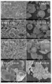
도 2는 본 실시예의 상이한 배율(각각 100nm 및 1μm)에서의 전형적인 SEM 이미지를 도시한다.
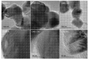
도 3은 본 실시예의 상이한 배율(각각 100nm 및 1 μm)에서의 LMOA 분말의 전형적인 SEM 이미지를 도시한다.
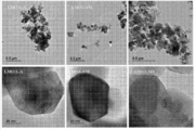
도 4는 본 실시예의 (a) LMO-A, (b) LMO-AM 및 (c) LMO-MA 캐소드 재료의 TEM 이미지, 및 이에 대응하는 HRTEM 이미지를 도시한다.
도 5는 본 실시예의 LMOAA, LMOAAM및 LMOAMA 캐소드 재료의 TEM 이미지, 및 이에 대응하는 HRTEM 이미지를 도시한다.
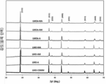
도 6은 본 실시예의 LMO 및 LMOA 분말의 XRD 패턴을 도시한다.
도 7은 본 실시예의 LMO 및 LMOA 샘플의 XPS Mn 2p3/2 스펙트럼을 도시한다.
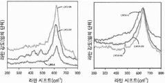
도 8은 본 실시예의 LMO 및 이들의 Al 도핑된 대응물의 라만 스펙트럼을 도시한다.
도 9는 본 실시예의 LMO 및 LMOA 분말의 FTIR 스펙트럼을 도시한다.
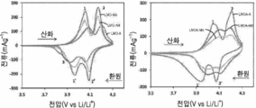
도 10은 본 실시예의 LMO 및 LMOA의 0.1 mVs-1 및 상온에서의 순환 전압-전류 그림을 도시한다.
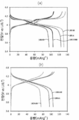
도 11은 본 실시예의 LMO 및 LMOA 분말의 0.1C 및 상온에서의 정전류 충- 방전을 도시한다.
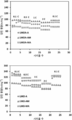
도 12는 본 실시예의 상이한 LMO 및 LMOA 기반 코인 셀에 대한 방전 용량 및 쿨롱 효율 대 사이클 수 그래프를 도시한다.
도 13은 본 실시예의 상이한 전류 밀도(0.2-2C) 및 실온에서 LMO 및 Al 도핑된 LMO의 3.5 내지 4.3V 범위에서의 용량 대 사이클 수를 도시한다.
도 14는 본 실시예의 스펙트럼을 피팅하는데 사용되는 등가 회로 (d) 및 LMO 및 LMOA 기반 코인 셀의 콜-콜 (Nyquist) 플롯을 도시한다.
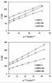
도 15는 본 실시예의 LMO 및 LMOA 기반 코인 셀의 Z' 대 ω1/2 곡선을 도시한다.DETAILED DESCRIPTION OF THE PREFERRED EMBODIMENTS The present invention will be described in detail below with reference to the accompanying drawings.
Figure 1 shows a schematic diagram of the microwave assisted solution combustion synthesis ('SCS') fabrication of LiMn 2 O 4 (LMO) and LiMn 1.7 Al 0.3 O 4 (LMOA) of this example.
Fig. 2 shows a typical SEM image at different magnifications (100 nm and 1 m, respectively) of this embodiment.
Figure 3 shows a typical SEM image of LMOA powder at different magnifications (100 nm and 1 [mu] m, respectively) of this embodiment.
Figure 4 shows a TEM image of (a) LMO-A, (b) LMO-AM and (c) LMO-MA cathode material in this embodiment, and the corresponding HRTEM image.
Figure 5 shows a TEM image of the LMOAA, LMOAAM and LMOAMA cathode materials of this embodiment, and a corresponding HRTEM image.
Figure 6 shows the XRD pattern of the LMO and LMOA powders of this example.
Figure 7 shows the XPS Mn 2p 3/2 spectrum of the LMO and LMOA samples of this example.
Figure 8 shows the Raman spectra of the LMOs and their Al-doped counterparts of this example.
Figure 9 shows the FTIR spectra of the LMO and LMOA powders of this example.
Fig. 10 shows a circulating voltage-current picture at 0.1 mVs < -1 > and room temperature of the LMO and LMOA of this embodiment.
Fig. 11 shows the constant current charge-discharge at 0.1C and normal temperature of the LMO and LMOA powders of this example.
12 shows the discharge capacity and Coulomb efficiency versus cycle number graph for the different LMO and LMOA based coin cells of this embodiment.
Figure 13 shows the capacity versus number of cycles at different current densities (0.2-2C) in this embodiment and 3.5-3.4V range of LMO and Al-doped LMO at room temperature.
Figure 14 shows an equivalent circuit (d) used to fit the spectrum of this embodiment and a Nyquist plot of LMO and LMOA based coin cells.
15 shows the Z 'versus? 1/2 curves of the LMO and LMOA based coin cells of this embodiment.
지금까지, 출원인은 LMO의 사이클링 성능을 향상시키는 3가지 수단, 즉; (i) 스피넬 구조를 리튬이 풍부하게 만드는 것 (Li-초과), (ii) 스피넬 구조를 다른 양이온 및 음이온으로 도핑하는 것, 및 (iii) 스피넬 구조를 금속 산화물(예를 들어, Y2O3)로 코팅하는 것만을 알고 있었다. 알루미늄(Al)은 전이 금속 원소보다 풍부하고 비독성이며 가격이 저렴하고 가볍기 때문에 더 유리한 도펀트이다. 또한, 출원인은 Al 도핑된 스피넬 LMO(LiAlxMn2-xO4)가 순수한 LMO보다 향상된 전기 화학적 성능을 나타낸다는 것을 알고 있다. Al은 산화 환원 비활성 도펀트이고; 구조의 안정화를 돕지만 방전 용량을 향상시키지는 못한다.To date, the Applicant has identified three means of improving the cycling performance of LMOs: (i) to the doping to make a spinel structure lithium-rich (Li- excess), (ii) a spinel structure as another positive and negative ions, and (iii) a metal oxide, a spinel structure (for example, Y 2 O 3 ). ≪ / RTI > Aluminum (Al) is a more favorable dopant because it is more abundant and nontoxic than transition metal elements, cheaper, and lighter. Applicants also know that Al-doped spinel LMO (LiAl x Mn 2-x O 4 ) exhibits improved electrochemical performance over pure LMO. Al is a redox-inactive dopant; It helps to stabilize the structure but does not improve the discharge capacity.
따라서, 본 발명의 목적은 LMO 스피넬 재료를 캐소드 재료로서 함유하는 전기 화학 전지의 사이클링 성능을 향상시킬 수 있는 LMO 스피넬 재료를 제공하는 것이다.It is therefore an object of the present invention to provide an LMO spinel material which can improve the cycling performance of an electrochemical cell containing LMO spinel material as a cathode material.
따라서, 본 발명의 일 측면에 따르면, 리튬-망간 옥사이드 스피넬 재료의 제조 방법으로서,Accordingly, in accordance with one aspect of the present invention, there is provided a method of producing a lithium-manganese oxide spinel material,
연소 합성에 의해 비가공된(raw) 리튬-망간 옥사이드(LMO) 재료를 제조하는 단계;Preparing a raw lithium-manganese oxide (LMO) material by combustion synthesis;
선택적으로, 전기화학 셀에서 캐소드 재료로 사용될 때 상기 LMO 스피넬 재료의 성능을 향상시킬 수 있는 도펀트를 도입하는 단계;Alternatively, introducing a dopant that can improve the performance of the LMO spinel material when used as a cathode material in an electrochemical cell;
선택적으로, 처리된 재료를 얻기 위하여 상기 비가공된 LMO 재료에 마이크로웨이브 처리를 가하는 단계;Optionally, applying microwave treatment to the unprocessed LMO material to obtain a treated material;
어닐링된 재료를 얻기 위하여 상기 비가공된 LMO 재료 또는 처리된 재료를 어닐링하는 단계; 및Annealing the unprocessed LMO material or treated material to obtain an annealed material; And
선택적으로, 상기 어닐링된 재료에 마이크로웨이브 처리를 가하는 단계;를 포함하고,Optionally, applying microwave treatment to the annealed material,
단, 1회 이상의 마이크로웨이브 처리가 이루어져 상기 리튬-망간 옥사이드(LMO) 스피넬 재료를 얻는, 리튬-망간 옥사이드 스피넬 재료의 제조 방법이 제공된다.However, there is provided a method for producing a lithium-manganese oxide spinel material, wherein at least one microwave treatment is performed to obtain the lithium-manganese oxide (LMO) spinel material.
'연소 합성'은 혼합물 전체에 걸쳐 반응물의 발열 반응을 개시하기 위해 반응 혼합물을 초기 고온을 받게하는 것을 포함하는 자체 전파(self-propagating) 고온 합성을 의미한다. 특히, 용액 연소 합성이 사용될 수 있다. 용액 연소 합성('SCS')는 용액 전체에 걸쳐 반응물의 발열 반응을 개시하기 위해 반응물의 균질 용액을 초기 고온에 노출시키거나 초기 고온을 받게 하는 것을 포함한다. 따라서, 상기 반응은 자체 유지 반응이며, 분말 또는 과립 생성물이 일반적으로 생성물로 얻어진다. 생성물 과립 또는 입자는 나노미터 스케일 범위일 수 있고, 즉 1 내지 100nm의 직경 또는 단면 치수를 가질 수 있다.&Quot; Combustion synthesis " refers to self-propagating high-temperature synthesis which involves subjecting a reaction mixture to an initial high temperature to initiate an exothermic reaction of the reactants throughout the mixture. In particular, solution combustion synthesis can be used. Solution combustion synthesis ('SCS') involves exposing a homogenous solution of a reactant to an initial high temperature or to receive an initial high temperature to initiate an exothermic reaction of the reactant throughout the solution. Thus, the reaction is a self-sustaining reaction, and a powder or granulation product is generally obtained as a product. The product granules or particles may be in the nanometer scale range, i.e., having a diameter or cross-sectional dimension of from 1 to 100 nm.
따라서, 반응물은 리튬 화합물 및 망간 화합물을 포함할 것이다. 상기 화합물은 발열 반응을 위한 산화제로서 기능할 수 있어야 하고, 또한 당연히 SCS가 사용될 때 균질 용액을 형성하기 위해 사용되는 용매에 용해되어야 한다. 따라서, 리튬 및 망간의 질산염, 아세트산 염, 황산염 및 탄산염이 사용될 수 있다; 그러나, SCS가 비가공된 분발/과립 LMO 재료를 제조하는데 사용될 때, 질산 리튬(LiNO3) 및 질산 망간(특히 Mn(NO3)2.4H2O)이 반응물로서 바람직하다. 따라서, 비가공된 LMO 재료는 고체 상태 방법으로 제조된다.Thus, the reactants will comprise a lithium compound and a manganese compound. The compound should be able to function as an oxidizing agent for the exothermic reaction and, of course, should be soluble in the solvent used to form a homogeneous solution when SCS is used. Thus, nitrates, acetates, sulfates and carbonates of lithium and manganese can be used; Lithium nitrate (LiNO 3 ) and manganese nitrate (especially Mn (NO 3 ) 2 .4H 2 O) are preferred as reactants, however, when SCS is used to make unprocessed flux / granular LMO materials. Thus, the unprocessed LMO material is produced in a solid state process.
용액에 사용된 용매는 물일 수 있다. 반응물의 혼합물 또는 균질 용액은 연소 보조제 또는 반응을 위한 연료를 포함할 수 있다. 상기 연료는 유기 연료일 수 있고, 요소, 글리세린, 하이드라지드, 수크로스 또는 시트르산일 수 있다; 그러나, 요소가 바람직하다.The solvent used in the solution may be water. The mixture or homogeneous solution of reactants may comprise a combustion aid or a fuel for the reaction. The fuel can be an organic fuel and can be urea, glycerin, hydrazide, sucrose or citric acid; However, an element is preferred.
따라서, 상기 용액은 수용액일 수 있다. 따라서, 공정은 상기 리튬 화합물, 상기 망간 화합물 및 상기 요소를 물에 용해시키는 단계를 포함할 수 있다. 용액이 받거나 노출되는 초기 고온 또는 상승 온도는 적어도 500℃, 바람직하게는 약 550℃일 수 있다. 약 600℃의 온도가 상기 용액이 받거나 노출되는 고온의 실용 상한이라고 믿어진다. 따라서, 출원인은 500℃ 미만의 온도에서 발열 반응이 단순히 개시되지 않거나, 또는 너무 느린 속도로 일어난다는 것을 발견하였고, 반면에 550℃ 초과, 특히 600℃ 초과의 온도에서 후속 마이크로웨이브 처리는 덜 두드러지고 심지어 중요하지 않게 된다.Thus, the solution may be an aqueous solution. Thus, the process may include dissolving the lithium compound, the manganese compound, and the urea in water. The initial high or rising temperature at which the solution is received or exposed may be at least 500 캜, preferably about 550 캜. A temperature of about 600 [deg.] C is believed to be the practical upper limit of the high temperature at which the solution is received or exposed. Applicants have therefore found that an exothermic reaction at temperatures below 500 ° C is not simply initiated or occurs at too slow a rate, whereas at temperatures above 550 ° C, especially above 600 ° C, subsequent microwave treatment is less noticeable It does not even matter.
발열 반응 또는 자체 유지 반응이 일어나는 동안, 즉 반응이 멈출 때까지(생성물의 형성이 더 이상 일어나지 않을 때까지) 상기 용액과 (생성물이 형성됨에 따라) 상기 생성물은 500℃ 내지 600℃의 고온을 계속 받을 수 있다. 그러나, 자체 유지 또는 발열 반응이 개시되어, 필요하다면, 예를 들어 온도 제어 또는 다른 목적으로 필요한 경우, 당연히 고온 노출을 중단할 수 있다.While the exothermic or self-sustaining reaction is taking place, i.e., until the reaction stops (until formation of the product no longer takes place), the solution and the product (as the product is formed) Can receive. However, self-sustaining or exothermic reactions are initiated and, if necessary, high temperature exposure can of course be stopped, for example if necessary for temperature control or other purposes.
SCS는 분말/과립 생성물을 빠르고, 간단하고, 효과적으로 생산하는 기술이다. 나타낸 바와 같이, 생성물이 완전히 형성될 때까지, 즉 반응물(특히 연료)이 더 이상 발열 반응에 참여하지 않을 때까지 발열 반응이 지속될 것이다. 전형적으로, 반응 시간, 즉 용액이 상승 온도 또는 고온에 처음 노출될 때부터 생성물이 더이상 형성되지 않을 때까지의 시간은 7 내지 12분의 범위에 있다.SCS is a technique for producing powder / granule products quickly, simply and effectively. As shown, the exothermic reaction will continue until the product is completely formed, i. E. The reactants (especially fuel) are no longer participating in the exothermic reaction. Typically, the reaction time, i.e. the time from when the solution is initially exposed to elevated temperature or high temperature to when the product is no longer formed, is in the range of 7 to 12 minutes.
상기 발열 반응은 대기압에서 수행될 수 있다.The exothermic reaction may be performed at atmospheric pressure.
본 발명의 일 구현예에 있어서, 비가공된 재료가 단순히 비가공된 리튬-망간 옥사이드 재료이도록, 도펀트 또는 임의의 다른 성분이 감지할 수 있을 정도로 용액 내에 존재하지 않을 수 있다.In one embodiment of the present invention, the dopant or any other component may not be present in the solution to such an extent that the raw material is simply an unprocessed lithium-manganese oxide material.
그러나, 본 발명의 다른 구현예에서, 상기 도펀트, 특히 알루미늄일 수 있는 도펀트가 존재할 수 있다. 상기 용액은 용해된 알루미늄 화합물을 함유할 수 있고, 여기서 알루미늄 화합물은 알루미늄 질산염, 특히 Al(NO3)2.9H2O일 수 있다. However, in other embodiments of the present invention, there may be a dopant that may be the dopant, especially aluminum. The solution may contain a soluble aluminum compound, wherein the aluminum compound is aluminum nitrate, specifically Al (NO 3) may be a 2 .9H 2 O.
마이크로웨이브 처리 또는 조사는 비가공된 LMO 재료 및/또는 어닐링된 재료를 마이크로웨이브(전형적으로 λ = 0.12236m, 600W)에 10분 내지 30분, 예를 들어 약 20분 동안 가하는 단계를 포함할 수 있다. 그러나, 마이크파로파 전력은 600W보다 작거나 클 수 있다.Microwave treatment or irradiation may involve applying unprocessed LMO material and / or annealed material to microwaves (typically lambda = 0.12236m, 600W) for 10 minutes to 30 minutes, for example, about 20 minutes have. However, the microwave power may be less than or greater than 600W.
비가공된 LMO 재료 또는 처리된 재료를 어닐링하는 단계는 상기 재료를 결정화하기에 충분히 높은 온도에서 수행될 수 있다. 따라서, 상기 어닐링하는 단계는 600℃ 내지 800℃ 의 온도, 예를 들어 700℃ 의 온도에서 수행될 수 있다. 상기 어닐링하는 단계는 목적하는 어닐링 정도를 달성하기에 충분히 긴 시간, 즉 목적하는 결정성을 달성하기에 충분히 긴 시간 동안 수행될 수 있다. 전형적으로, 상기 어닐링하는 단계는 8 내지 12 시간, 예를 들어 약 10시간이 걸린다.The step of annealing the unprocessed LMO material or treated material may be performed at a temperature high enough to crystallize the material. Accordingly, the annealing may be performed at a temperature of 600 ° C to 800 ° C, for example, 700 ° C. The annealing step may be performed for a time long enough to achieve the desired degree of annealing, i. E., A time long enough to achieve the desired crystallinity. Typically, the annealing step takes from 8 to 12 hours, for example, about 10 hours.
본 발명은 또한 본 발명의 제1 측면의 방법에 의해 제조될 때 LMO 스피넬 재료로 확장된다.The present invention also extends to LMO spinel materials when made by the process of the first aspect of the present invention.
본 발명의 제2 측면에 따르면, 전기화학 셀이 제공되고, 상기 전기화학 셀은 셀 하우징, 캐소드, 애노드 및 상기 셀 하우징 내의 전해질을 포함하고, 상기 캐소드가 상기 애노드로부터 전자적으로 절연되나, 상기 전해질에 의해 상기 애노드에 전기화학적으로 결합되고, 상기 캐소드가 본 발명의 제1 측면의 방법에 의해 제조된 LMO 스피넬 재료를 포함한다.According to a second aspect of the present invention there is provided an electrochemical cell comprising: a cell housing; a cathode; an anode; and an electrolyte in the cell housing, wherein the cathode is electronically isolated from the anode, And the cathode comprises an LMO spinel material produced by the method of the first aspect of the present invention.
상기 캐소드는 상기 LMO 스피넬 재료, 블랙 카본, 및 바인더(예를 들어, 폴리비닐리덴 플루오라이드)를 예를 들어 N-메틸-2-피롤리돈과 같은 용매 내에 포함할 수 있다.The cathode may contain the LMO spinel material, black carbon, and a binder (e.g., polyvinylidene fluoride) in a solvent such as, for example, N-methyl-2-pyrrolidone.
상기 애노드는 리튬 금속을 포함할 수 있다.The anode may comprise a lithium metal.
상기 전해질은 비수성 전해질일 수 있고, 예를 들어, LiPF6이거나 이를 포함할 수 있다.The electrolyte may be a non-aqueous electrolyte, for example, LiPF 6 or the like.
상기 셀 하우징, 캐소드, 애노드 및 전해질은 상기 캐소드로부터의 리튬이 상기 애노드의 적어도 일부를 형성하도록 충전 포텐셜을 상기 셀에 인가할 수 있도록 배열될 수 있고, 상기 셀의 충전 및 방전 중에 상기 셀의 평균 망간 원자가 상태는 약 3.5+ 이상, 예를 들어 3.8+ 이상이다.The cell housing, the cathode, the anode, and the electrolyte may be arranged to apply a charging potential to the cell such that lithium from the cathode forms at least a portion of the anode, and during charging and discharging of the cell, The manganese valence state is at least about 3.5+, such as at least 3.8+.
본 발명의 제3 측면에 따르면, 전기화학 셀의 제조 방법이 제공되고, 상기 전기 화학 셀의 제조 방법은 셀 하우징에 전해질, 애노드 및 캐소드를 로딩하는 단계를 포함하고, 상기 캐소드는 본 발명의 제1 측면의 방법에 의해 제조된 LMO 스피넬 재료를 포함한다.According to a third aspect of the present invention, there is provided a method of manufacturing an electrochemical cell, the method comprising loading an electrolyte, an anode and a cathode in a cell housing, Lt; RTI ID = 0.0 > LMO < / RTI > spinel material produced by the method of one aspect.
본 발명의 제4 측면에 따르면, 전기화학 셀의 운전 방법이 제공되고, 상기 운전 방법은,According to a fourth aspect of the present invention, there is provided a method of operating an electrochemical cell,
본 발명의 제2 측면의 전기화학 셀에 충전 전위를 인가하여, 상기 캐소드로부터의 리튬이 상기 애노드의 적어도 일부를 형성하는 단계; 및Applying a charge potential to the electrochemical cell of the second aspect of the present invention such that lithium from the cathode forms at least a portion of the anode; And
상기 셀의 방전 전위가 리튬 금속에 대하여 3.5 내지 4.3 V에 도달하도록 허용하는 단계;를 포함하고,And allowing the discharge potential of the cell to reach 3.5 to 4.3 V relative to the lithium metal,
상기 셀의 충전 및 방전 중에 평균 망간 원자가 상태는 3.5+ 이상이다.The average manganese valence state during charging and discharging of the cell is 3.5+.
상기 셀의 방전 전위는 리튬 금속에 대하여 3.8 내지 4.2V에 도달하도록 허용될 수 있다. 상기 셀의 충전 및 방전 중에 평균 망간 원자가 상태는 약 3.8+ 이상일 수 있다.The discharge potential of the cell may be allowed to reach 3.8-4.2 V relative to the lithium metal. The average manganese valence state during charging and discharging of the cell may be about 3.8+.
실시예Example
실험 섹션Experimental section
화학 물질 및 재료Chemicals and materials
질산리튬 (LiNO3), 질산망간 4수화물 (Mn(NO3)2·4H2O), 요소 (CO(NH2)2) 및 질산알루미늄 9수화물 (Al(NO3)2·9H2O)을 Sigma-Aldrich로부터 구입하였다. 카본 블랙, N-메틸-2피롤리돈(NMP), 폴리비닐리덴 플루오라이드(PVDF), 알루미늄 포일(MTI Corporation USA, 50 μm 두께), 리튬 금속 (Sigma-Aldrich,50 μm 두께), 리튬 헥사플루오로포스파이트 (LiF6P), 에틸렌 카보네이트 (EC), 디에틸 카보네이트 (DEC), 및 디메틸 카보네이트 (DMC)를 LMO 캐소드의 제조 및 코인 셀의 제조 동안 사용하였다. 또한, 이 화학 물질들은 Sigma-Aldrich에서 구입하였다. 이러한 모든 화학 물질들은 추가 정제 없이 사용하였다.Lithium nitrate (LiNO 3), manganese nitrate tetrahydrate (Mn (NO 3) 2 · 4H 2 O), urea (CO (NH 2) 2) and aluminum nitrate nonahydrate (Al (NO 3) 2 · 9H 2 O) Was purchased from Sigma-Aldrich. Carbon black, N-methyl-2 pyrrolidone (NMP), polyvinylidene fluoride (PVDF), aluminum foil (MTI Corporation USA, 50 μm thick), lithium metal (Sigma-Aldrich, 50 μm thick) Fluorophosphite (LiF 6 P), ethylene carbonate (EC), diethyl carbonate (DEC), and dimethyl carbonate (DMC) were used during the preparation of the LMO cathode and during the manufacture of the coin cell. These chemicals were also purchased from Sigma-Aldrich. All these chemicals were used without further purification.
LMO 및 Al 도핑된 LMO 분말의 합성 Synthesis of LMO and Al-doped LMO Powders
질산리튬, 질산망간 및 요소로부터 직접 스피넬 LMO 기반 분말을 합성하는 데 용액 연소 합성법을 사용하였다. LiNO3 (1.10g, 0.0398몰), Mn(NO3)2·4H2O (8.00g, 0.0797몰) 및 요소 (2.87g, 0.120몰)를 탈이온수 (20.00ml)에 용해시키고, 출발 물질이 완전히 용해될 때까지 교반하였다. 생성된 용액을 로(furnace)에서 550℃에서 약 7분 동안 가열하여 나노입자 크기 범위의 흑색 분말 생성물을 얻었다. 상기 분말을 막자사발과 막자를 사용하여 분쇄한 후 이것에 하기의 열 처리를 가하였다. 마이크로웨이브 조사의 영향을 연구하기 위하여, 두 배치의 분말을 합성하였다. 이 분말을 어닐링 전,후 각각에 600W에서 20분 동안 마이크로웨이브 조사(Anton Paar Multiwave 3000 시스템, λ = 0.12236m 을 사용)를 처리하였다. 상기 샘플 분말을 관로(50 mm, MTI Corporation)를 사용하여 700℃에서 10시간 동안 어닐링하였다. 상기 얻어진 분말은 마이크로웨이브 처리된 후 어닐링된 리튬 망간 디옥사이드(LMO-MA) 및 어닐링된 후 마이크로웨이브 처리된 리튬 망간 디옥사이드(LMO-AM)였다. 어닐링만 된 LMO 분말 샘플은 LMO-A라 명명하였다. LMO 알루미늄 도핑 분말을 상기와 동일한 절차를 사용하여 제조하였다. LiMn1.7Al0.3O4 분말은 1.10g의 LiNO3, 6.80g의 Mn(NO3)2·4H2O, 1.80g의 Al(NO3)2·9H2O 및 2.87g의 요소를 사용하여 제조하였다. 상기 분말들은 유사하게 LMOA-A, LMOA-AM 및 LMOA-MA로 명명하였다. 상기 분말들은 어닐링 단계와 마이크로웨이브 조사 단계 사이에서 분쇄하였다. 상기 절차의 개략도를 도 1에 도시하였다.Solution combustion synthesis was used to synthesize spinel LMO based powders directly from lithium nitrate, manganese nitrate and urea. LiNO 3 (1.10 g, 0.0398 mol), Mn (NO 3 ) 2 .4H 2 O (8.00 g, 0.0797 mol) and urea (2.87 g, 0.120 mol) were dissolved in deionized water (20.00 ml) Stir until complete dissolution. The resulting solution was heated in a furnace at 550 DEG C for about 7 minutes to obtain a black powder product in the nanoparticle size range. The powder was pulverized using a mortar and pestle, and then subjected to the following heat treatment. In order to investigate the effect of microwave irradiation, two batches of powders were synthesized. The powder was subjected to microwave irradiation (Anton Paar Multiwave 3000 system, using λ = 0.12236 m) at 600 W for 20 minutes before and after annealing, respectively. The sample powder was annealed at 700 占 폚 for 10 hours using a pipeline (50 mm, MTI Corporation). The obtained powder was microwave-treated and then annealed lithium manganese dioxide (LMO-MA) and annealed and microwaved lithium manganese dioxide (LMO-AM). The sample of the annealed LMO powder was named LMO-A. LMO aluminum doped powder was prepared using the same procedure as above. LiMn 1.7 Al 0.3 O 4 powder was prepared using 1.10 g of LiNO 3 , 6.80 g of Mn (NO 3 ) 2 .4H 2 O, 1.80 g of Al (NO 3 ) 2 .9H 2 O and 2.87 g of urea Respectively. The powders were similarly named LMOA-A, LMOA-AM and LMOA-MA. The powders were milled between an annealing step and a microwave irradiation step. A schematic diagram of the above procedure is shown in Fig.
재료의 특성 평가Characteristic evaluation of materials
제조된 분말을 2.00kV의 가속 전압을 갖는 LEO 1525 전계 발광 스캐닝 현미경(FE-SEM)을 사용하여 연구하였다. 약 0.1mg의 샘플을 카본 테이프 위에 놓은 다음, 충전을 방지하기 위해 코팅하여 각각의 샘플을 제조하였다. HRTEM 측정은 전자 소스로서 LAB6필라멘트를 사용하는 Joel HRJEM-2100 현미경 유닛을 사용하여 수행하였다. 측정은 200kV에서 전자 빔을 사용하여 수행하였다. 약 2mg의 샘플을 에탄올에 용해시켰다. 이어서, 상기 혼합물을 10분 동안 초음파 처리하여 샘플을 용매에 균질하게 분산시켰다. 이어서, 샘플 용액 한 방울을 탄소 구리 격자(200 메쉬) 위에 펼쳐 실온에서 건조시켰다. 이어서, 상기 격자를 분석을 위해 TEM 챔버에 장착하였다. X-선 회절(XRD) 분석을 위하여, 45kV 및 40mA에서 운전하는 방사원으로 λ=1.5046A의 파장을 갖는 CuKα 방사선을 사용하는 PANalytical X'Pert Pro 회절계를 사용하는 X-선 회절 분광기를 사용하여 상기 샘플 분말을 분석하였다. XRD 회절그램(diffractogram)을 0 내지 90°의 스캔 범위에서 얻었다. Al Kα 방사선(1486.6eV)를 갖는 Kratos Axis Ultra-DLD 시스템(Shimadzu)을 사용하여 XPS 측정을 수행하였다. 결합 에너지는 탄소의 C 1s 레벨(284.6eV)을 기준으로 하여 보정하였다. FTIR 스펙트럼은 Perkin Elmer Spectrum 100 FTIR 분광기를 사용하여 400 내지 4000 범위에서 기록하였다. 분석은 다이아몬드 결정 탐침을 사용하여 수행하였고, 대기를 백그라운드로 사용하였다. 샘플의 펠렛을 KBr과 1:3 비율로 혼합하고 디스크법으로 제조하였다. 상기 펠렛은 IR 방사선에 대한 우수한 투명도를 제공하는 두께를 사용하여 제조하였다. 라만 측정은 샘플의 작은 선택된 영역에 레이저빔의 초점을 맞추기 위한 10배 대물 렌즈, 30mW 녹색 아르곤 레이저(514nm 파장) 여기 소스, 및 1800 라인/mm 격자 모노크로미터가 장착된, 공냉식 CCD 검출기를 갖춘 Horiba Jobin Yvon 분광계를 사용하여 대기 중에서 수행하였다. 상기 샘플을 공초점 현미경의 스테이지에 올려 놓고, 카메라로 모니터에 시각화하였다. 레이저가 공초점 현미경을 통해 샘플 위로 초점을 맞추었다. 산란된 방사선이 렌즈를 통해 다시 수집되어 일련의 광학 장치를 통해 전송된 다음 격자 모노크로미터의 입구 슬릿에 초점을 맞추었다. 라만 스펙트럼은 약 3cm-1의 해상도로 스토크스 측면(stokes side)에서 1000cm-1까지 측정하였다. 상기 스펙트럼(산란된 방사선의 세기 대 파수)을 컴퓨터에 의해 처리하였다. 상기 측정은 실온에서 이루어졌다.The prepared powders were studied using a LEO 1525 electroluminescent scanning microscope (FE-SEM) with an acceleration voltage of 2.00 kV. About 0.1 mg of the sample was placed on carbon tape and each sample was prepared by coating to prevent charging. HRTEM measurements were performed using a Joel HRJEM-2100 microscope unit using LAB6 filaments as the electron source. Measurements were performed using an electron beam at 200 kV. About 2 mg of the sample was dissolved in ethanol. The mixture was then sonicated for 10 minutes to homogeneously disperse the sample in the solvent. A drop of the sample solution was then spread over a carbon copper lattice (200 mesh) and dried at room temperature. The grating was then mounted in a TEM chamber for analysis. For X-ray diffraction (XRD) analysis, an X-ray diffraction spectrometer using a PANalytical X'Pert Pro diffractometer using CuKa radiation with a wavelength of? = 1.5046A as a radiation source operating at 45 kV and 40 mA The sample powder was analyzed. An XRD diffractogram was obtained at a scan range of 0 to 90 degrees. XPS measurements were performed using a Kratos Axis Ultra-DLD system (Shimadzu) with Al Kα radiation (1486.6 eV). The bond energy was corrected based on the C 1s level of carbon (284.6 eV). The FTIR spectra were recorded in the range of 400 to 4000 using a
리튬 이온 배터리 코인 셀의 제조 Manufacture of lithium ion battery coin cell
전기화학적 연구를 위한 캐소드를 카본 블랙 10% 및 용매로서 N-메틸-2-피롤리돈(NMP) 중의 폴리비닐리덴 플루오라이드(PVDF) 바인더 10%와 혼합된, 제조된 전기활성 LMO 분말 80%을 함유하는 슬러리를 제조함으로써 제조하였다. 닥터 블레이드법(doctor-blade method)을 사용하여 상기 슬러리를 집전체로서 알루미늄 포일 상에 도포하였다. 코팅된 알루미늄 포일을 진공 하에 110℃ 에서 12시간 동안 건조시켰다. 이어서, 코팅된 캐소드 포일을 가압하여 균일한 층을 형성하고 원형 디스크 전극을 상기 코팅된 알루미늄 포일로부터 천공시켰다. 상기 전극을 다시 진공 오븐에서 가열하여 상기 전극에 흡착되어있을 수 있는 물질을 분해시키고 상기 전극 표면에 부착된 물을 증발시켰다. 고온을 사용한 경우의 전극 손상을 방지하기 위해 진공을 사용하였는데, 이는 오븐 내의 진공 환경이 물의 비점을 낮추기 때문이다. 상기 전극을 80℃에서 적어도 6시간 동안 가열하였다. 이어서, 코인 셀을 제조할 때 글로브 박스와 동일한 환경에 있도록, 코인 셀을 제조하기 전에 상기 전극을 2시간 동안 글로브 박스에 넣었다.The cathode for electrochemical studies was prepared by mixing 80% of the prepared electroactive LMO powder mixed with 10% carbon black and 10% polyvinylidene fluoride (PVDF) binder in N-methyl-2-pyrrolidone (NMP) ≪ / RTI > The slurry was applied as a current collector onto an aluminum foil using a doctor-blade method. The coated aluminum foil was dried under vacuum at < RTI ID = 0.0 > 110 C < / RTI > for 12 hours. The coated cathode foil was then pressed to form a uniform layer and a circular disk electrode was punched from the coated aluminum foil. The electrode was again heated in a vacuum oven to decompose the substance adsorbed on the electrode and evaporate the water attached to the electrode surface. Vacuum was used to prevent electrode damage when high temperatures were used because the vacuum environment in the oven lowers the boiling point of water. The electrode was heated at 80 < 0 > C for at least 6 hours. Then, the electrode was placed in a glove box for 2 hours before manufacturing the coin cell, so as to be in the same environment as the glove box when manufacturing the coin cell.
전기화학적 측정은 코인형 셀(CR 2032)을 사용하여 수행하였다. 상기 코인 셀(미도시)은 각각 제조된 LMO 분말로 제조된 캐소드, 애노드로서의 리튬 금속 및 비수성 전해질을 포함한다. 또한, 상기 코인셀은 각각 전극으로부터 셀 케이스 또는 하우징으로의 전기적 접속을 제공하기 위하여 스테인리스 스틸로 제조된 스페이서 및 코인 셀이 밀봉될 때 캐소드와 애노드가 최대로 접촉할 수 있도록 구성 요소들에 압력을 가하는 스프링을 포함한다. 캐소드와 애노드 사이의 세퍼레이터에 충분한 전해질을 넣었다.Electrochemical measurements were performed using a coin cell (CR 2032). The coin cells (not shown) each include a cathode made of the LMO powder produced, a lithium metal as the anode, and a non-aqueous electrolyte. In addition, the coin cells each have a spacer made of stainless steel to provide electrical connection from the electrode to the cell case or housing, and a pressure to the components to maximize the contact between the cathode and the anode when the coin cell is sealed And a spring for applying a force. A sufficient electrolyte was put into the separator between the cathode and the anode.
상기 코인 셀을 초고순도 아르곤 기체가 충전된 글로브 박스에 조립하였다. 리튬이 매우 반응성이 높고 물과 빠르게 반응하기 때문에, H2O 및 O2 의 농도를 0.5 ppm 미만으로 유지하였다. 또한, 전해질은 물의 영향을 받고; 물은 전해질을 산성으로 만들 수 있고, 이는 캐소드 재료를 용해시켜 코인 셀의 고장을 일으킬 수 있다. 1:1:1 부피비의 EC/ DEC/DMC 내의 1M LiPF6 용액을 제조하여 전해질로서 사용하였다. LiF6P (7.5945 g)를 EC(20ml), DEC(20ml) 및 DMC(20ml) 용매의 혼합물에 용해시켰다. 생성된 용액을 잘 흔들어 염을 완전히 용해시켰다. 실험실 환경의 습기로 인해 전해질이 산성이 될 수 있기 때문에 상기 전해질은 글로브 박스(MBRAUN MB10 compact)에서 제조되었다. 상기 전해질을 코인 셀의 제조에 사용하기 전에 글로브 박스에 하루 동안 방치하였다. Celgard 폴리프로필렌계 막을 세퍼레이터로 사용하였다. 코인 셀의 모든 구성 요소를 정렬한 후, Compact Hydraulic Crimping Machine(MSK-110)으로 코인 셀을 밀봉하였다. 크림퍼의 압력이 코인 셀의 운전에 작동에도 기여하므로 중요하다. 코인 셀을 밀봉하기 위한 크림퍼의 압력을 750 psi로 설정하였다. 제조 후, 개방 회로 전압을 측정하고 전기화학적 측정을 수행하기 전에 상기 코인 셀을 24시간 동안 방치하였다. 이것은 전해질이 전극을 완전히 적시고 코인 셀이 안정화되도록 하였다.The coin cell was assembled into a glove box filled with ultra-high purity argon gas. Because lithium is highly reactive and reacts rapidly with water, the concentrations of H 2 O and O 2 were kept below 0.5 ppm. Also, the electrolyte is affected by water; Water can make the electrolyte acidic, which can dissolve the cathode material and cause failure of the coin cell. A 1M LiPF 6 solution in a 1: 1: 1 volume ratio of EC / DEC / DMC was prepared and used as the electrolyte. LiF 6 P (7.5945 g) was dissolved in a mixture of EC (20 ml), DEC (20 ml) and DMC (20 ml) solvent. The resulting solution was shaken well to completely dissolve the salt. The electrolyte was prepared in a glove box (MBRAUN MB10 compact) because the electrolyte in the laboratory environment can become acidic due to moisture. The electrolyte was left in a glovebox for one day before use in the manufacture of a coin cell. A Celgard polypropylene-based membrane was used as a separator. After aligning all the components of the coin cell, the coin cell was sealed with a Compact Hydraulic Crimping Machine (MSK-110). The pressure of the crimper is important because it also contributes to the operation of the coin cell. The pressure of the crimper to seal the coin cell was set to 750 psi. After fabrication, the open circuit voltage was measured and the coin cell was left for 24 hours before performing electrochemical measurements. This allowed the electrolyte to completely wet the electrode and stabilize the coin cell.
코인 셀의 전기화학적 특성 평가Electrochemical Characterization of Coin Cells
제조된 LMO 캐소드 샘플을 작동 전극으로 사용하고 리튬 금속을 반대 전극 및 기준 전극으로 사용하는 코인 셀을 사용하여 순환 전압 전류법(Cyclic voltammetry, CV)을 수행하였다. Bio-Logic 사이언스 VMP3 기반 기기를 사용하여 3.5V 내지 4.3V 범위에 걸쳐 0.1mVs-1의 속도로 스캔을 수행하였다. EIS 측정은 10mV의 AC 신호 진폭으로 100kHz에서 1mHz 범위에서 수행하였다. 데이터 수집 및 분석은 EC-lab V10.32 소프트웨어를 사용하여 Bio-Logic 사이언스 VMP3 기반 기기로 수행하였다. 충전-방전 용량 및 사이클 성능(속도 성능)은 Maccor 4000 배터리 테스터를 사용하여 3.5 내지 4.3V 사이의 상이한 C-속도(충전-방전 속도)에서 측정하였다. 모든 전기화학적 성능 측정은 상온에서 수행하였다.Cyclic voltammetry (CV) was performed using the prepared LMO cathode sample as the working electrode and a coin cell using lithium metal as the counter electrode and reference electrode. Scans were performed at a rate of 0.1 mVs < -1 > over a range of 3.5 V to 4.3 V using a Bio-Logic Science VMP3 based instrument. EIS measurements were performed in the range of 100 kHz to 1 mHz with an AC signal amplitude of 10 mV. Data collection and analysis was performed with Bio-Logic Science VMP3-based instrument using EC-lab V10.32 software. The charge-discharge capacity and cycle performance (rate performance) were measured at different C-rates (charge-discharge rate) between 3.5 and 4.3 V using a Maccor 4000 battery tester. All electrochemical performance measurements were performed at room temperature.
결과 및 토론Results and discussion
FESEM 특성 평가FESEM characterization
저배율 및 고배율에서 LMO 및 Al 도핑된 LMO의 SEM 이미지를 각각 도 2 및 도3에 도시하였다. LMO의 경우, 이미지가 팔면체 1차 입자의 응집에 의해 형성된 구형 2차 입자를 묘사한다. 제조된 모든 샘플은 팔면체형 1차 입자를 갖는데, 이는 마이크로웨이브 조사가 입자의 모양을 변화시키지 않는다는 것을 의미한다. 1차 입자(결정체) 및 2차 입자의 평균 크기는 LMO-A의 경우 132nm 및 5.20 μm; LMO-AM의 경우 196 nm 및 6 μm; LMO-MA의 경우 133 nm 및 3.37 μm이다. LMO-AM은 좁은 입자 크기 분포를 나타내고, 이는 어닐링 단계 이후의 마이크로웨이브 조사가 분말의 성장 동력을 도와 따라서 입자 크기를 증가시키는 것을 나타낸다. LMO-A와 달리, LMO-MA는 작은 크기의 입자로 좁은 크기 분포를 나타냈으며, 이는 어닐링 단계 이전의 마이크로웨이브 조사가 스피넬 결정화 공정을 거의 완료하여 가장 기본적인 샘플(LMO-A)에 비하여 고온 어닐링을 통한 입자 성장을 더 느리게 만든다. 시판 샘플(LMO-comm)은 일반적으로 마이크론 크기이며, 이는 제조 방법이 일반적으로 결정 성장을 초래하는 긴 어닐링 기간을 포함해야한다는 것을 나타낸다.SEM images of LMO and Al-doped LMO at low and high magnification are shown in Figures 2 and 3, respectively. In the case of LMO, the image depicts spherical secondary particles formed by agglomeration of octahedral primary particles. All samples produced have octahedral primary particles, which means that the microwave irradiation does not change the shape of the particles. The mean size of primary particles (crystals) and secondary particles were 132 nm and 5.20 μm for LMO-A; 196 nm and 6 μm for LMO-AM; And 133 nm and 3.37 μm for LMO-MA. LMO-AM exhibits a narrow particle size distribution, indicating that microwave irradiation after the annealing step helps the growth power of the powder and thus increases the particle size. In contrast to LMO-A, LMO-MA exhibited a narrow size distribution with small size particles, indicating that microwave irradiation prior to the annealing step almost completed the spinel crystallization process, resulting in high temperature annealing Which slows particle growth through. Commercially available samples (LMO-comm) are typically of micron size, indicating that the fabrication process should generally include a long anneal period resulting in crystal growth.
Al 도핑된 LMO 샘플의 SEM 이미지(도 3)에서, 샘플은 도핑되지 않은 LMO 샘플(도 2)와 비교할 때, 일반적으로 나노 크기의 입자이다. 일반적으로 도핑된 샘플의 표면적이 도핑되지 않은 샘플의 표면적보다 넓다는 것을 고려하면, 이는 놀랄 일이 아니다[15]. 입자의 균일성과 응집은 LMOA-A 샘플에 비하여 LMOA-AM 및 LMOA-MA에서 더 크다. 입자 크기 분포는 다양하지만, 50 nm 이하의 입자 크기 모집단 범위에서, LMOA-A가 지배적이다; 즉, LMOA-A (~ 62%) > LMOA-AM (~ 36%) > (LMOA-MA (~24%). LMOA-A가 소량의 대형 입자(120-130nm)를 함유하고 있음을 관찰하는 것은 흥미롭지만, 마이크로웨이브 조사시 최대 입자 크기는 80nm이며, 이는 마이크로웨이브 조사가 입자를 수축시킬 수 있어 이후에 나타난 바와 같이 결정도 및 전기화학적 성능을 향상시킬 수 있음을 나타낸다.In the SEM image (FIG. 3) of the Al-doped LMO sample, the sample is typically nano-sized particles as compared to the undoped LMO sample (FIG. 2). This is not surprising given that the surface area of the doped sample is generally larger than the surface area of the undoped sample [15]. The uniformity and aggregation of particles are greater in LMOA-AM and LMOA-MA than in LMOA-A sample. Although the particle size distribution varies, LMOA-A predominates in the particle size population range below 50 nm; LMOA-A (~ 62%)> LMOA-AM (~ 36%)> (LMOA-MA (~ 24%). LMOA-A contains a small amount of large particles (120-130 nm) Although interesting, the maximum particle size in microwave irradiation is 80 nm, which indicates that microwave irradiation can shrink the particles and improve crystallinity and electrochemical performance as shown later.
HRTEM 특성 평가HRTEM characterization
LMO 분말 및 이들의 Al 도핑된 대응물의 TEM 이미지를 각각 도4 및 도5에 나타내었다. LMO-AM은 LMO-A 및 LMO-MA와 비교할 때 상대적으로 큰 입자로 구성된다. LMO 분말은 이들의 LMOA 대응물과 비교하여 큰 입자 크기를 나타내는데, 이는 SEM 결과와 일치한다. HRTEM 현미경 사진은 격자 간격이 명확하게 관찰될 수 있기 때문에 분말이 결정성임을 증명한다. 평균 d-간격은 LMO-A, LMO-AM 및 LMO-MA에 대해 각각 0.57, 0.49, 0.42nm로 계산되었다. Al 도핑된 LMO에 대하여, 평균 d-간격은 LMOA-A, LMOA-AM 및 LMOA-MA에 대해 각각 0.61, 0.55, 0.56nm였다. 상기 d-간격 값은 격자 구조에서 (111)면을 명확하게 확인한다. Al 도핑된 LMO의 약간 더 높은 d-간격 값은 스피넬 구조로의 외부 Al의 성공적인 도입을 나타낸다.TEM images of the LMO powders and their Al-doped counterparts are shown in Figures 4 and 5, respectively. LMO-AM is composed of relatively large particles as compared to LMO-A and LMO-MA. The LMO powders show larger particle sizes compared to their LMOA counterparts, which is consistent with the SEM results. HRTEM micrographs demonstrate that the powder is crystalline because the lattice spacing can be clearly observed. The mean d-spacing was calculated to be 0.57, 0.49, and 0.42 nm for LMO-A, LMO-AM, and LMO-MA, respectively. For Al-doped LMO, the average d-spacing was 0.61, 0.55, and 0.56 nm for LMOA-A, LMOA-AM, and LMOA-MA, respectively. The d-spacing value clearly identifies the (111) plane in the lattice structure. The slightly higher d-spacing value of the Al-doped LMO indicates the successful introduction of the external Al into the spinel structure.
XRD 특성 평가Evaluation of XRD characteristics
LMO 및 Al 도핑된 LMO 분말의 XRD 패턴을 도 6에 도시하였다. 순수 스피넬 LiMn2O4 및 LiAl0.3Mn1.7O4 재료를 확인하는 회절 피크가 잘 발달되어있다. 상기 피크는 공간 그룹 Fd-3m 공간을 갖는 스피넬 LiMn2O4 (JCPDS 파일 번호 No. 88-1749)의 특성 회절로 인덱싱되고, (111), (311), (222), (400), (331), (551), (440), 및 (531) 면에 대응된다. 모든 분말에 대한 XRD 패턴은 유사하지만 LMO-MA의 상대 강도가 LMO-A 및 LMO-AM의 상대 강도보다 훨씬 강한데, 이는 LMO-MA가 LMO-A 및 LMO-AM보다 결정성이 높음을 의미한다. 스피넬의 전기화학적 성질에 있어 스피넬 LMO 재료의 높은 결정성은 중요하다.The XRD pattern of the LMO and Al-doped LMO powder is shown in Fig. Diffraction peaks confirming the pure spinel LiMn 2 O 4 and LiAl 0.3 Mn 1.7 O 4 materials are well developed. The peak is indexed by the characteristic diffraction of spinel LiMn 2 O 4 (JCPDS file No. 88-1749) with space group Fd-3m space and is characterized by (111), (311), (222), 331), (551), (440), and (531). The XRD patterns for all powders are similar but the relative intensities of LMO-MA are much stronger than those of LMO-A and LMO-AM, indicating that LMO-MA is more crystalline than LMO-A and LMO-AM . The high crystallinity of the spinel LMO material is important in the electrochemical properties of spinel.
표 1은 스피넬 분말의 격자 파라미터 값을 요약한 것이다. 표 1은 몇가지 흥미로운 정보를 제공한다. 첫째로, LMO-A는 가장 큰 격자 파라미터를 보이는데, 이는 마이크로웨이브 조사 및/또는 알루미늄 도핑에 따라 감소한다. 격자 수축은 Mn3+의 감소와 Mn4 + 이온의 증가를 의미한다(Mn3 +의 반경(0.66 Å)이 Mn4 +의 반경(0.60 Å)보다 크기 때문이다)[30]. 둘째로, Al 도핑된 샘플의 격자 파라미터의 극적인 수축이 있는데, 이는 Mn3 +의 직경(0.66 Å)이 Al3 +의 직경(0.53 Å)보다 크고 Mn-O의 결합 길이(1.90 Å)가 Al-O의 결합길이(1.62 Å)보다 길어서, Al3 +이 스피넬 구조의 16d 사이트에서 Mn3 +를 대체할 때, 단위 셀의 수축을 초래한다는 사실 때문이다. 일반적으로, 격자 수축은 스피넬 구조의 안정성을 증가시키며, 이는 Jahn-Teller 왜곡의 억제에 유용하다. (311)/(400) 피크의 강도 비가 작을수록, 재료의 결정성이 더 높고, 따라서, 가장 작은 값을 갖는 2개의 마이크로웨이브 처리된 샘플(LMO-MA 및 LMOA-AM)이 다른 샘플에 비해 더 결정성이다.Table 1 summarizes the lattice parameter values of the spinel powder. Table 1 provides some interesting information. First, LMO-A shows the largest lattice parameter, which decreases with microwave irradiation and / or aluminum doping. Lattice contraction (due larger than the radius (0.66 Å) radius (0.60 Å) of the Mn + 4 of the Mn + 3) reduction of the Mn 3+ and means an increase in the Mn + 4 ion [30]. Second, there is a dramatic contraction of the lattice parameter of the Al-doped sample because the diameter of Mn 3 + (0.66 A) is larger than the diameter of Al 3 + (0.53 A) and the bond length of Mn-O (1.90 A) Is longer than the bond length of -O (1.62 A), which is why it causes shrinkage of the unit cell when Al 3 + replaces Mn 3 + at the 16d site of the spinel structure. In general, lattice shrinkage increases the stability of the spinel structure, which is useful for suppressing Jahn-Teller distortion. (LMO-MA and LMOA-AM) having the smallest value are higher than those of the other samples, as the intensity ratio of the (311) / (400) It is more crystalline.
표 1: LMO 및 LMOA 분말의 격자 파라미터 비교값Table 1: Lattice parameter comparison values of LMO and LMOA powders
XPSXPS 특성 평가 Character rating
스피넬 내의 Mn3+ 및 Mn4+ 의 실제 양을 결정하기 위하여, 분말 스피넬 샘플에 대해 XPS 실험을 수행하였다. 연구된 재료의 Mn 2p3/2 XPS 스펙트럼을 도 7에 도시하였다. 넓은 Mn 2p3/2 피크는 Mn 이온의 두 가지 상이한 산화 상태를 얻기 위해 2개의 피크로 디콘볼루션되었다. 평균 망간 원자가 상태(nMn)를 포함하는 Mn3+ 대 Mn4+ 의 비율을 표 2에 나타내었으며, XRD 분석에서 관찰된 격자 수축을 뒷받침한다. 나중에 나타내었듯이, nMn이 약 3.5 이상인 LMO 재료는 연속 충-방전 사이클링 시 용량을 유지할 수 있었다. 어떠한 마이크로웨이브 조사도 없이 제조된 LMO(LMO-A) 및 상업용 LMO 재료(LMO-comm) 모두 각각 3.165 이상 및 3.400 이상의 nMn 값을 제공한다는 사실이 흥미로운데, 이는 LMO 분말의 nMn이 약 3.5 이상이어야 한다는 일반적인 견해를 분명히한다. 더 흥미로운 점은 LMO-A가 마이크로웨이브 조사 처리되어 LMO-AM를 얻었을 때, 격자 수축(8.256 Å에서 8.244 Å로)이 관찰되어 nMn이 약3.5 이상이 되었다는 것이다. 이 결과는 마이크로웨이브 조사가 이 경우 산화제의 역할(즉, 과량의 Mn3+를 Mn4+로 전환)을 한다는 것을 시사한다.In order to determine the actual amounts of Mn 3+ and Mn 4+ in the spinel, XPS experiments were performed on the powdered spinel samples. The Mn 2p 3/2 XPS spectrum of the material studied is shown in FIG. The broad Mn 2p 3/2 peak was deconvoluted into two peaks to obtain two different oxidation states of Mn ions. The ratios of Mn 3+ to Mn 4+ , including the average manganese valence state (n Mn ), are shown in Table 2 and support the lattice shrinkage observed in the XRD analysis. As shown later, LMO materials with n Mn greater than about 3.5 were able to maintain capacity during continuous charge-discharge cycling. It is manufactured without any microwave irradiation LMO (LMO-A) and commercial LMO material (LMO-comm) in fact interesting to that enjoy the n Mn value more than, and 3.400, respectively 3.165, which is about 3.5 of the LMO powder n Mn Or more. More interestingly, when LMO-A was microwave irradiated to obtain LMO-AM, the lattice constriction (8.256 A to 8.244 A) was observed and the n Mn was about 3.5 or higher. These results suggest that microwave irradiation will in this case act as an oxidant (ie, convert excess Mn 3+ to Mn 4+ ).
표 2: Mn 2p3 /2 피크 위치 및 Mn3 +/Mn4 + 양이온 분포Table 2: Mn 2p 3/2 peak position and the 3 + Mn / Mn + 4 cation distribution
라만 분광학 특성 평가Raman Spectroscopic Characterization
Jahn-Teller 왜곡에 대한 합성법의 영향을 조사하기 위하여 라만 분광법을 사용하였으며, 이는 망간 양이온 주위의 산소 배위의 근-이웃(near-neighbour) 환경을 직접적으로 분석함으로써 이루어진다. LMO 및 이들의 Al 도핑된 대응물의 라만 스펙트럼을 도 8에 도시하였다. LiMn2O4 가 일반적으로 625 cm-1 주위의 강한 피크 및 550 내지 600 cm-1에서 넓고 덜 명확한 숄더를 보여주고, 500 cm-1 이하에서 몇가지 불명확한 구조를 가지므로, 라만 스펙트럼은 문헌과 일치한다 [32]. 500 cm-1 이하의 진동수 영역(즉, 350 내지 400 cm-1)의 스펙트럼의 특징은 LiO4 사면체에 속하고, 450 내지 650 cm-1의 진동수 영역의 특징은 MnO6 팔면체의 진동 모드에 속한다. 600 내지 650 cm-1 주위의 피크는 Oh 7 분광 공간 그룹에서 A1g 종에 할당된 MnO6 그룹의 Mn-O의 대칭 신축 진동 때문이다. 이러한 피크의 확장은 양이온-음이온 결합 길이 및 LMO에서 발생하는 다면체 왜곡(즉, Mn3+O6 및 Mn4+O6 팔면체의 신축 진동)에 기인할 수 있다. Al 도핑된 LMO의 경우, 샘플에 대한 Mn-O 진동의 특징적인 라만 피크는 LMOA-A, LMOA-AM 및 LMOA-MA 각각에 대하여 약 637, 642 및 632 cm-1에서 관찰되었다. 도핑되지 않은 LMO에 비해 피크가 이동하는 것은 팔면체 자리의 일부에 Al3+ 이온이 존재하기 때문이다. Mn4+ 은 약 90 cm-1의 스핀 오비탈 스플릿팅(splitting)을 갖는 Mn3+와 비교하여 약 138 cm-1의 큰 스핀 오비탈 상수를 갖고, 따라서 Al3+ 이온으로 도핑한 후 Mn4+-O 의 결합 강도가 증가하고, 따라서 피크 이동이 발생한다.Raman spectroscopy was used to investigate the effect of the synthesis method on Jahn-Teller distortion, which is achieved by directly analyzing the near-neighbor environment of the oxygen coordination around the manganese cations. The Raman spectra of LMO and their Al-doped counterparts are shown in FIG. Because LiMn 2 O 4 is typically 625 cm -1 to show the periphery of the strongest peak, and 550 to 600 wide and less clear shoulder in cm -1, of some unknown structure at 500 cm -1 or less, the Raman spectrum is described by the Consistent [32]. The spectral characteristics of the frequency region of 500 cm -1 or less (i.e., 350 to 400 cm -1 ) belong to the LiO 4 tetrahedron, and the characteristic of the frequency region of 450 to 650 cm -1 belongs to the oscillation mode of the MnO 6 octahedron . The peak around 600 to 650 cm -1 is due to the symmetric stretching vibration of Mn-O of the MnO 6 group assigned to the A 1 g species in the O h 7 spectral space group. The expansion of such a peak can be attributed to cation-anion bond length and polyhedral distortion (i.e., stretching vibration of Mn 3+ O 6 and Mn 4+ O 6 octahedra) occurring in LMO. For Al-doped LMOs, characteristic Raman peaks of Mn-O oscillation on the samples were observed at about 637, 642 and 632 cm -1 for LMOA-A, LMOA-AM and LMOA-MA, respectively. The shift of the peak compared to the undoped LMO is due to the presence of Al 3+ ions in a part of the octahedral site. Mn 4+ and Mn 3+ is compared with a spin-orbital splitting (splitting) of about 90 cm -1 has a large spin-orbital constant of about 138 cm -1, Therefore, after doped with Al 3+ ions Mn 4+ The bonding strength of -O increases, and hence peak shift occurs.
FTIR 특성 평가FTIR characterization
M이 리튬 또는 망간 금속인, 제조된 샘플에서 M-O 및 M-M 결합에 대한 마이크로웨이브의 영향을 연구하는데 FTIR을 사용할 수 있다. 도 9는 LMO 및 Al 도핑된 LMO의 FTIR 스펙트럼을 보여준다. LMO 샘플의 스펙트럼은 지문 영역에서 두 개의 강한 흡수 밴드에 의해 지배된다. 이 밴드는 LMO-A, LMO-AM 및 LMO-M에 대하여 각각 약 613/515, 616/514 및 612/507 cm-1에서 나타난다. Al 도핑된 LMO의 경우, 이 피크는 LMOA-A, LMOA-AM 및 LMOA-MA에 대하여 각각 635/523, 632/523, 및 635/522 cm-1에서 나타난다. 문헌으로부터 LiMn2O4의 FTIR 스펙트럼은 약 615 및 513 cm-1에서의 강한 흡수 밴드가 특징적인 것으로 알려져있고 [3], 따라서 얻은 결과는 문헌과 일치한다. 이러한 2개의 IR 지배 밴드는 MnO6 그룹의 비대칭 신축 모드와 관련된 고진동수 밴드와 함께, F1u 종 때문이다[3]. 이러한 FTIR 피크는 도핑되지 않은 LMO의 경우 615 및 513 cm-1에서 관찰된 피크로부터 약간 이동한다. 이것은 Al 도핑 및 마이크로웨이브로 인한 Mn(Al)O6 팔면체의 상대적으로 강한 결합 때문이다. 팔면체에서 Al-O 결합(512 kJ mol- 1)은 Mn-O 결합(402 kJ mol- 1)보다 강하다. Al 도핑 및 마이크로웨이브 조사는 평균 Mn-O 결합을 감소시킴으로써 스피넬 구조의 안정성을 증가시키고, Mn 이온의 평균 산화 상태를 증가시킨다.FTIR can be used to study the effect of microwaves on MO and MM bonding in prepared samples where M is lithium or a manganese metal. Figure 9 shows the FTIR spectra of LMO and Al-doped LMO. The spectrum of the LMO sample is dominated by two strong absorption bands in the fingerprint domain. This band appears at about 613/515, 616/514 and 612/507 cm -1 for LMO-A, LMO-AM and LMO-M, respectively. For Al-doped LMO, this peak appears at 635/523, 632/523, and 635/522 cm -1 for LMOA-A, LMOA-AM and LMOA-MA, respectively. It is known from the literature that the FTIR spectrum of LiMn 2 O 4 is characterized by strong absorption bands at about 615 and 513 cm -1 [3], and the results obtained are consistent with the literature. These two IR dominant bands are due to the F 1u species, together with the high frequency band associated with the asymmetric stretching mode of the MnO 6 group [3]. This FTIR peak shifts slightly from the peak observed at 615 and 513 cm < -1 > for undoped LMO. This is due to the relatively strong binding of Mn (Al) O 6 octahedra due to Al doping and microwaves. The Al-O bond (512 kJ mol - 1 ) in the octahedra is stronger than the Mn - O bond (402 kJ mol - 1 ). Al doping and microwave irradiation increases the stability of the spinel structure by decreasing the average Mn-O bond and increases the average oxidation state of Mn ions.
LMO 분말의 전기화학적 연구Electrochemical study of LMO powder
순환 전압 전류법(Cyclic Voltammetry)Cyclic Voltammetry
0.1mVs-1의 느린 스캔 속도에서의 다양한 LMO 및 알루미늄 도핑된 LMO로부터 제조된 리튬 이온 배터리 코인 셀의 순환 전압 전류 전개를 도 10에 도시하였다. 각각의 재료는 2개의 산화 환원 쌍(1/1' 및 2/2')을 나타내며, LMO-MA는 3.874V 이하의 숄더 피크로 나타나는 저강도 캐소드 피크(피크 3)를 나타내며, 이는 격자의 미세한 구조 재배치가 발생하는, 초기 사이클 동안의 '형성 사이클' 때문일 수 있다 [4]. 착물 (LiAlxMn2-xO4, 여기서 LMO 및 LMOA 각각에 대하여 x는 0 및 0.3이다)의 2개의 산화 환원 쌍의 존재는 리튬 이온의 삽입 또는 추출이 반응 (2) 및 (3)에 따른 두 단계로 진행되는 것을 나타낸다 [5].The cyclic voltage-current evolution of a lithium ion battery coin cell fabricated from various LMO and aluminum doped LMOs at a slow scan rate of 0.1 mVs < -1 > is shown in Fig. Each material represents two redox pairs (1/1 'and 2/2') and LMO-MA represents a low intensity cathode peak (peak 3) with a shoulder peak below 3.874 V, May be due to the 'formation cycle' during the initial cycle, where structural relocation occurs [4]. The presence of two redox pairs of the complex (LiAl x Mn 2-x O 4, where x is 0 and 0.3 for LMO and LMOA, respectively) indicates that insertion or extraction of lithium ions is carried out in reactions (2) and And [5].
LiAlxMn2 - xO4 → Li0 . 5AlxMn2 - xO4 + 0.5 Li+ + 0.5 e- (2)LiAl x Mn 2 - x O 4 → Li 0 . 5 Al x Mn 2 - x O 4 + 0.5 Li + + 0.5 e - (2)
Li0 . 5AlxMn2 - xO4 → 2λ-MnO2 + 0.5 Li+ + 0.5 e- (3)Li 0 . 5 Al x Mn 2 - x O 4 ? 2 ? - MnO 2 + 0.5 Li + + 0.5 e - (3)
여기서, Li0.5AlxMn2-xO4이 LiAlxMn2-xO4보다 안정하다. 보다 명확하게, 첫번째 애노드 피크는 Li-Li 상호작용이 일어나는 사면체(8a) 사이트의 절반에서 Li 이온이 제거되기 때문이다. 두번째 애노드 피크는 나머지 사면체 사이트로부터 Li 이온이 제거되기 때문이고, 여기서는 Li-Li 상호작용이 일어나지 않는다; 즉, λ-MnO2 로 이어지는 리튬 방출(de-intercalation)이 일어난다 [6].Here, Li 0.5 Al x Mn 2-x O 4 is more stable than LiAl x Mn 2-x O 4 . More specifically, the first anode peak is because Li ions are removed from half of tetrahedral (8a) sites where Li-Li interaction takes place. The second anode peak is due to the removal of Li ions from the remaining tetrahedral sites, where Li-Li interaction does not occur; This leads to de-intercalation leading to λ-MnO 2 [6].
산화 환원 반응의 역학 및 가역성에 대한 통찰력을 제공하기 위하여, 애노드 대 캐소드 피크 전류의 비율(I pa/I pc), 애노드의 피크 - 피크 분리 및 피크 전위(D E p), 및 반파장 전위 또는 충전 전위와 방전 전위의 중간점(D E 1/2)에 관하여 CVs를 분석하여 표 3에 요약하였다. 가역 프로세스의 경우, I pa/I pc는 대략 1이어야 하며, D E p (즉, 애노드 및 캐소드 피크 전위의 차이, |E pa| - |E pc|)는 이상적으로 약 0.060V여야 한다. 표 3으로부터, 실험 오차의 한계 내에서, 산화 환원 쌍이 동일한 (D E 1/2)으로 가역적임을 분명하게 알 수 있다. 이론적으로, 개방 회로 전위(OCV)는 (D E 1/2)와 같다.In order to provide insight into the dynamics and reversibility of the redox reaction, the ratio of the anode to the cathode peak current ( I pa / I pc ), the peak-to-peak separation and peak potential ( D E p ) The CVs were analyzed with respect to the midpoint between the charge potential and the discharge potential ( D E 1/2 ) and summarized in Table 3. For reversible processes, I pa / I pc should be approximately 1, and D E p (ie, the difference between the anode and cathode peak potentials, | E pa | - | E pc |) should ideally be about 0.060V. From Table 3 it can be clearly seen that within the limits of the experimental error, the redox pair is reversible to the same ( D E 1/2 ). Theoretically, the open circuit potential (OCV) is equal to ( D E 1/2 ).
표 3: LMO 및 Al 도핑된 LMO 재료로부터 나타난 산화 환원 쌍의 순환 전압 전류 데이터Table 3: Cyclic Voltammetric Data of Redox Pairs from LMO and Al-Doped LMO Materials
정전류 충-방전 Constant current charge-discharge
도 11은 제조된 LMO와 이들의 Al 도핑된 대응물에 대하여 실온에서 얻어진 전형적인 정전류 충-방전 곡선을 도시한다. 코인 셀은 Li/Li+에 대하여 3.5 내지 4.3 V의 전압 범위에서, 14 mA g-1의 정전류(0.1C의 전류율, 1C는 140 mAg-1로 가정)에서 사이클링 되었다.Figure 11 shows a typical constant current charge-discharge curve obtained at room temperature for the prepared LMO and their Al-doped counterpart. The coin cell was cycled at a constant current of 14 mA g -1 (assuming a current rate of 0.1 C and 1 C at 140 mAg -1 ) in the voltage range of 3.5 to 4.3 V vs. Li / Li + .
LMO 기반 코인 셀에 대하여(도 11a), CV 결과에서 관찰되는 바와 같이, 2단계 리튬 삽입으로 인한, 충전 및 방전 곡선 모두에서 나타나는 약 4.12V 및 4.00V에서의 2개의 뚜렷한 안정기를 관찰하였다. 4.00V에서의 안정기는 반응 (2)에 대응하는 CV 결과에서 관찰되었고, 4.12V에서의 안정기는 반응 (3)에 대응한다. 이러한 안정기는 도 11a에서 볼 수 있듯이 LMO-MA에서 더 길고 LMO-AM 곡선에서 더 짧은데, 이는 셀이 사이클링 될 때, 다른 캐소드 재료에서보다 LMO-MA 캐소드 재료에서 더 많은 리튬 이온이 추출된다는 것을 나타낸다. 이러한 피크는 단상(single phase) 스피넬 LMO 구조에 대한 문헌과 잘 일치한다. LMO 종과는 달리, Al 도핑된 LMO(도 11b)는 2개의 전위 안정기를 나타내지 않았고, 단순한 전위 감소만이 관찰되었다. 이는 단조로운 전위 변화가 전위 범위에서 단상 반응이 가능하기 때문이라는, LiAl0.3Mn1.7O4에 대한 Myung의 연구 결과[7]와 매우 잘 일치한다. Al 도핑된 LMO 샘플의 방전 용량은 Al 도핑되지 않은 LMO 샘플의 방전 용량보다 낮으며, 이는 스피넬 구조에서 산화 환원 활성인 Mn3+이 산화 환원 비활성인 Al3+로 대체되기 때문이다.For the LMO based coin cell (Fig. 11a), two distinct stabilizers at about 4.12 V and 4.00 V, which are seen in both the charge and discharge curves due to the two stage lithium insertion, are observed, as observed in the CV results. The ballast at 4.00V was observed in the CV results corresponding to reaction (2), and the ballast at 4.12V corresponds to reaction (3). This stabilizer is longer in the LMO-MA and shorter in the LMO-AM curve, as can be seen in FIG. 11A, indicating that more lithium ions are extracted from the LMO-MA cathode material than in other cathode materials when the cell is cycled . These peaks are in good agreement with the literature on single phase spinel LMO structures. Unlike the LMO species, the Al-doped LMO (FIG. 11B) did not show two potential stabilizers, only a simple dislocation reduction was observed. This is in very good agreement with the results of Myung's study [7] on LiAl 0.3 Mn 1.7 O 4, in which monotonic changes in potential are due to the ability of single-phase reactions in the potential range. The discharge capacity of the Al-doped LMO sample is lower than the discharge capacity of the non-Al-doped LMO sample because Mn 3+, which is a redox active in the spinel structure, is replaced by Al 3+ , which is redox-inactive.
용량 유지율 및 쿨롱 효율 Capacity retention and coulomb efficiency
본 발명의 중요한 특징은 용량 유지율 또는 연속 사이클링 시 용량 저하를 줄이거나 완전히 제거하는 캐소드 재료의 능력이다. 사이클 수에 대한 방전 용량의 비교 플롯을 도 12에 도시하였다. 초기 방전 용량이 127 mAhg-1인 LMO-A (nMn = 3.165+)는 50회 사이클 후에 단지 78%의 방전 용량을 유지하였다. 초기 방전 용량이 94 mAhg-1인 LMO-AM(nMn = 3.498+)는 50회 사이클 후에 91%의 방전 용량을 유지하였다. 131 mAhg-1의 높은 초기 방전 용량을 갖는 LMO-MA(nMn = 3.541+)는 50회 사이클 후에 초기 방전 용량의 95%를 유지하였고, 초기 방전 용량이 105 mAhg-1인 LMO-comm(nMn = 3.400)는 50회 사이클 후에 초기 용량의 90%를 유지하였다. 모든 Al 도핑된 LMO는 더 낮은 방전 용량을 보였으나, 흥미롭게도, 50회 사이클 후에 그것의 초기 용량의 약 100%를 유지하였다. 이러한 결과로부터, (i) nMn ∼ 3.5+ 인 LMO 및 Al 도핑된 LMO 재료(즉, LMO-AM, LMO-MA 및 LMOA-AM)는 가장 높은 용량 및 가장 높은 용량 유지율을 제공하고, (ii) 가장 성능이 좋은 LMO 및 Al 도핑된 LMO(즉, nMn ∼ 3.5+)는 어닐링 단계의 전 또는 후에 마이크로웨이브 조사 단계를 수행함으로써 얻을 수 있다는 것을 명백히 알 수 있다. LMOA 재료의 방전 용량은 다음과 같이 감소했다: LMOA-AM (107 mAhg-1, nMn = 3.493+) > LMOA-A (95 mAhg-1, nMn = 3.310+) > LMOA-MA (75 mAhg-1, nMn = 3.690+). 따라서, 가장 성능이 좋은 LMO 및 LMOA(고용량 및 용량 유지율)는 nMn ∼ 3.5+인 LMO 및 LMOA인 것으로 결론지을 수 있다. Mn에 대해 3.31+의 낮은 산화 상태를 갖는 LMOA-A가 약 3.5+, 3.54+ 및 3.69+의 더 높은 nMn 값을 갖는 LMO-AM, LMO-MA 및 LMOA-MA보다 우수한 용량 유지율을 나타냈다. 이러한 결과는 3.47+의 낮은 nMn 값을 갖는 LiMn1.9Ti0.1O4 가 3.5+ 초과의 더 높은 nMn 값을 갖는 LiMn1.9Al0.1O4, LiMn1.9Al0.05Ti0.05O4, 및 LiMn1.85Ti0.075Li0.075O4보다 나은 용량 유지율을 나타낸다는 Shin 및 Manthiram의 결과 [8]와 일치한다. 차이점은 증가된 nMn 값 이외의 요소가 용량 유지율에서 역할을 수행할 수 있음을 의미한다. 그러나, 이 실시예의 결과는 높은 용량 유지율이 nMn > 3.50+에서만 얻을 수 있다고 데이터로부터 예측한 다른 기술자의 결과와 모순된다 [9, 10]. 예를 들어, 최근 Raguparthy [11]는 이중 도핑된 LMO(Zn 및 Ti을 도펀트로 사용하여)가 nMn > 3.6+에서 최고의 성능을 나타낸다고 발표하였다. Shin 및 Manthiram (JECS 2004) [9] 는 nMn > 3.58+에서 최고의 성능을 나타낸다고 발표하였다. 또한, Zhang 등 [1]은 마이크로웨이브 조사를 어닐링 단계의 가열원으로 사용하여 LMO 및 이중 도핑된 LMO(Ni 및 Mg로 도핑)을 얻었고, 가장 성능이 좋은 이중 도핑된 LMO는 nMn가 3.571+인 것으로 발표하였다. 그들의 재료는 짧은 합성 기간 동안 얻어졌으나, 흥미로운 사실은 nMn가 3.503+인, 얻어진 LMO(0.5 내지 1 μm의 평균 입자 크기)가 나쁜 용량 유지율을 나타내고, 이는 마이크로웨이브 조사를 단지 빠른 제조를 달성하기 위해 사용하는 것을 넘어서 LMO의 전기화학을 향상시키기 위해 활용할 수 있다는 것을 나타낸다는 사실이다. 일반적으로, nMn ∼ 3.5+이고 Jahn-Teller 효과가 없는 LMO 및 도핑된 LMO는 합성 단계에서 마이크로웨이브 조사를 전략적으로 사용하여 얻을 수 있다. 사실, nMn > 3.5+만의 요인 뿐만 아니라 입자의 성질, 격자 파라미터, 및 전략적인 마이크로웨이브 조사와 같은 다른 요인에 의해 Jahn-Teller 효과가 제거된다.An important feature of the present invention is the ability of the cathode material to reduce or completely eliminate capacity retention or capacity degradation during continuous cycling. A comparison plot of discharge capacity versus number of cycles is shown in Fig. LMO-A (n Mn = 3.165 +) with an initial discharge capacity of 127 mAhg- 1 maintained a discharge capacity of only 78% after 50 cycles. LMO-AM (n Mn = 3.498 +) with an initial discharge capacity of 94 mAhg- 1 maintained a discharge capacity of 91% after 50 cycles. LMO-MA (n Mn = 3.541+ ) having a high initial discharge capacity of 131 mAhg -1 was maintained for 95% of the initial discharge capacity after 50 cycles, n (the initial discharge capacity of 105 mAhg -1 LMO-comm Mn = 3.400) retained 90% of the initial capacity after 50 cycles. All Al-doped LMOs showed lower discharge capacity, but interestingly, they maintained about 100% of its initial capacity after 50 cycles. These results show that (i) LMO and Al-doped LMO materials (i.e., LMO-AM, LMO-MA and LMOA-AM) with n Mn to 3.5+ provide the highest capacity and highest capacity retention rates, ) It can be clearly seen that the best performing LMO and Al-doped LMO (i.e., n Mn ~ 3.5+) can be obtained by performing the microwave irradiation step before or after the annealing step. The discharge capacity at the LMOA material was reduced, as follows: LMOA-AM (107 mAhg -1 , n Mn = 3.493+)> LMOA-A (95 mAhg -1, n Mn = 3.310+)> LMOA-MA (75 mAhg -1 , n Mn = 3.690+). Therefore, it can be concluded that the best performing LMO and LMOA (high capacity and capacity retention) are LMO and LMOA with n Mn ~ 3.5+. LMOA-A with a low oxidation state of 3.31+ against Mn showed better capacity retention than LMO-AM, LMO-MA and LMOA-MA with higher n Mn values of about 3.5+, 3.54+ and 3.69+. These results indicate that LiMn 1.9 Ti 0.1 O 4 having a low n Mn value of 3.47+ has a higher n Mn value of more than 3.5+ LiMn 1.9 Al 0.1 O 4 , LiMn 1.9 Al 0.05 Ti 0.05 O 4 , and LiMn 1.85 Ti It is consistent with the results of Shin and Manthiram [8] that exhibit better capacity retention than 0.075 Li 0.075 O 4 . The difference means that factors other than the increased n Mn value can play a role in the capacity maintenance rate. However, the results of this example contradict the results of other descriptors predicted from the data that high capacity retention rates can be obtained only at n Mn > 3.50 + [9, 10]. For example, recently Raguparthy [11] reported that double doped LMOs (using Zn and Ti as dopants) show the best performance at n Mn > 3.6+. Shin and Manthiram (JECS 2004) [9] reported that n Mn > 3.58+ exhibited the best performance. In addition, Zhang et al. [1] obtained LMO and double doped LMO (doped with Ni and Mg) using microwave irradiation as a heating source in the annealing step. The best performance double doped LMO has n Mn of 3.571 + . Their material was obtained during a short synthesis period, but it is interesting to note that the obtained LMO (average particle size of 0.5 to 1 μm) with n Mn of 3.503+ exhibits poor capacity retention, which leads to microwave irradiation only to achieve rapid manufacturing It can be used to improve the electrochemistry of LMO beyond the use of it. Generally, LMOs and doped LMOs with n Mn ~ 3.5+ and no Jahn-Teller effect can be obtained by strategically using microwave irradiation in the synthesis step. In fact, the Jahn-Teller effect is eliminated by other factors such as particle nature, lattice parameters, and strategic microwave irradiation as well as factors of n Mn > 3.5+.
쿨롱 효율(CE)는 사이클링 중에 셀 내에서 발생하는 기생 반응(예를 들어, 물의 전기 분해 및 기타 산화 환원 반응)의 양을 측정한 것으로, 식 (4)에 의해 정의된다 [12]:Coulomb efficiency (CE) is the amount of parasitic reaction (eg, electrolysis of water and other redox reactions) occurring in a cell during cycling and is defined by Equation (4) [12]:
![]()
![]()
여기서, Q out은 방전 사이클 동안 배터리를 나가는 전하량이고 Q in은 충전 사이클 동안 배터리로 들어가는 전하량이다. 기생 반응으로 인해 용량 저하가 나타나고 배터리의 수명에 부정적인 영향을 미친다. 도 12로부터, 50회 사이클 후의 쿨롱 효율은 다음과 같은 경향을 따른다: LMO-MA (~99%) > LMO-A (98.5%) > LMO-AM (98.1%) > LMO-comm (90.2%), 이는 LMO-MA가 우수한 사이클링 안정성, 가역성 및 증가된 사이클 수명을 나타내는 최상의 쿨롱 효율을 나타낸다는 것을 의미한다. 또한, Al 도핑된 LMO는 우수한 쿨롱 효율을 나타냈다; LMOA-A (99.3%) > LMOA-AM (98.5%) ∼ LMO-A (98.5%) > LMOA-MA (98%). Where Q out is the amount of charge leaving the battery during the discharge cycle and Q in is the amount of charge entering the battery during the charge cycle. A parasitic reaction causes a drop in capacity and negatively affects battery life. 12, the coulombic efficiency after 50 cycles follows the following trend: LMO-MA (~99%)> LMO-A (98.5%)> LMO-AM (98.1%)> LMO- , Which means that LMO-MA exhibits the best coulombic efficiency with excellent cycling stability, reversibility and increased cycle life. In addition, the Al-doped LMO showed excellent coulombic efficiency; LMOA-A (99.3%)> LMOA-AM (98.5%) to LMO-A (98.5%)> LMOA-MA (98%).
표 4: LMO 및 Al 도핑된 LMO의 전기화학 데이터 대 결정 화학 데이터의 요약Table 4: Electrochemical data of LMO and Al-doped LMO versus summarized chemical data
(Å)Lattice parameter
(A)
속도 성능Speed performance
분말의 속도 성능을 0.1, 0.5, 1 및 2C의 상이한 충전 속도에서 평가하였다(1C=140mAg-1로 가정). 도 13은 LMO 분말의 속도 성능을 도시한다. 충전 속도는 5 사이클마다 증가했다. 더 높은 충전 속도에서 충전 중에 Li 이온이 빠르게 제거되고(방출) 방전 중에 제거된 Li 이온 전부가 캐소드로 되돌아갈 충분한 시간이 없기 때문에(삽입), 충전 속도가 증가함에 따라 용량이 감소하였다. Jahn-Teller 왜곡으로부터 발생하는 구조의 왜곡 때문에 충전 속도가 증가함에 따른 안정기의 감소는 스피넬 LMO 시스템에서 일반적으로 크다. 도 13에서 볼 수 있듯이, 상이한 충전 속도에 대한 초기 용량의 차이가 작기 때문에, 높은 충전 속도에서의 감소는 LMO-MA 및 LMO-AM 샘플에서 크게 개선되었다. 따라서, 코인 셀은 마이크로웨이브 처리된 샘플인 LMO-AM 및 LMO-MA에서 우수한 사이클 안정성을 보였다.The speed performance of the powder was evaluated at different charge rates of 0.1, 0.5, 1 and 2C (assuming 1 C = 140 mAg -1 ). 13 shows the velocity performance of the LMO powder. Charging rate increased every 5 cycles. Since Li ions were rapidly removed during charging at higher charging rates (discharging) and there was not enough time (insertion) for all of the Li ions removed during discharging to return to the cathode (insertion), the capacity decreased as the charging rate increased. The reduction of the ballast as the filling rate increases due to the distortion of the structure resulting from the Jahn-Teller distortion is generally large in the spinel LMO system. As can be seen in FIG. 13, the reduction in high fill rates was greatly improved in the LMO-MA and LMO-AM samples, since the difference in initial capacity for different fill rates was small. Thus, the coin cell showed excellent cycle stability in microwave treated samples LMO-AM and LMO-MA.
전기화학 임피던스 분광법Electrochemical impedance spectroscopy
전기화학 임피던스 분광법(EIS)는 리튬 이온 삽입/방출의 동역학을 연구하고 리튬 이온 확장 계수를 결정하는 중요한 기술이다. 임피던스 스펙트럼을 CV 측정(약 4.0V)에서 결정된 이론적인 OCV ∼ D E 1/2에서 측정하였다. 각각의 스펙트럼은 실온에서 얻었고 셀은 각각의 전압에서 1시간 동안 평형되었다. 도 14는 LMO 및 Al 도핑된 LMO의 실험적 나이퀴스트(Nyquist) 플롯 및 피팅된 나이퀴스트 플롯을 비교한다. 실험 데이터는 도 14(d)에 도시된 등가 회로로 만족스럽게 피팅되었다. 피팅 파라미터는 전해질, 세퍼레이터 및 전극의 전기 전도도로 인한 전극 시스템의 용액 옴 저항(ohmic resistance) (R s); 전극 표면 상에 형성된 고체-전해질 계면 층에 기인하는 저항 및 정전 용량(capacitance)을 지칭하는 표면 막 저항(R f) 및 일정 위상 요소(constant phase element)(CPE f), 전극과 전해질 사이의 계면에서 발생하는 리튬 삽입/방출 프로세스에 대응하는 전하 이동 저항(Rct) 및 계면 정전 용량(CPE Li), 및 저진동수 영역에서 직선 경사선(∼45°)으로 표시되는 활성 물질의 입자와 전해질 사이의 리튬 이온의 고체 상태 확산을 나타내는 Warburg 요소(Z w)를 포함한다.Electrochemical impedance spectroscopy (EIS) is an important technique for studying the dynamics of lithium ion implantation / release and determining the lithium ion expansion coefficient. The impedance spectra were measured at the theoretical OCV to D E 1/2 determined at the CV measurement (about 4.0 V). Each spectrum was obtained at room temperature and the cell was equilibrated for 1 hour at each voltage. Figure 14 compares an experimental Nyquist plot and a fitted Nyquist plot of LMO and Al-doped LMO. The experimental data was satisfactorily fitted to the equivalent circuit shown in Fig. 14 (d). The fitting parameters include the solution ohmic resistance ( R s ) of the electrode system due to the electrical conductivity of the electrolyte, the separator and the electrode; ( R f ) and a constant phase element ( CPE f ) designating the resistance and capacitance due to the solid-electrolyte interface layer formed on the electrode surface, the interface between the electrode and the electrolyte (R ct ) and interfacial capacitance ( CPE Li ) corresponding to the lithium insertion / release process occurring in the electrolyte membrane and between the particles of the active material and the electrolyte represented by a straight line (~ 45 °) in the region of low vibration frequency And a Warburg element ( Z w ) that represents the solid state diffusion of lithium ions in the electrolyte.
모든 화합물에 대한 임피던스 스펙트럼은 1MHz 내지 10Hz의 진동수 영역에서 하나의 명확한 반원과 저진동수 영역에서 경사가 있는 직선으로 구성된다. 이러한 진동수 영역에서 보이는 반원은 실제로는 고진동수 및 중간 진동수에서의 반원이 겹친것이다. 일반적으로, 등가 회로로부터도 명백한 것과 같이, 고진동수 영역에서의 반원은 표면 막 저항(R f)으로 인한 것이고, 중간 진동수 영역에서의 반원은 리튬 전하 전달 저항(R Li) 및 계면 정전 용량(CPE Li)으로 인한 것이다. 가장 중요한 파라미터(R s , R f, 및 R Li)를 표 5에 요약하였다. 표 5로부터, 리튬 이온 전도도(R Li)는 LMO-MA > LMO-A > LMOA-MA로 감소한다. 이러한 경향은 리튬 이온 전도도가 입자 크기 및 Mn3+ 농도의 조합에 의해 제어되고, 입자 크기가 작고 Mn3+ 농도가 높을수록 리튬 이온 전도도가 더 크다는 것을 분명히 보여준다. 동일한 현상이 Al 도핑된 LMO 재료에도 적용된다(즉, LMOA-A > LMOA-AM > LMOA-MA). LMOA-A가 그 대응물인 LMO-A(RLi가 19.64이고 Rf가 13.7임)에 비하여 더 작은 RLi (~ 11) 및 더 큰 Rf (~ 82)를 나타냈다. 이것은 문헌(ECA와 그의 참고 문헌 [12])과 일치하며, 알루미늄이 산화 환원 침묵이고 Rf 가 하기의 관계식 (5)에 따라 SEI 막의 전도도와 관련이 있다는 것을 예상해야한다.The impedance spectra for all compounds consist of a straight line with a slope in one clear semicircle and low vibration area in the frequency range of 1 MHz to 10 Hz. The semicircles seen in this frequency range are actually superimposed semicircles at high and intermediate frequencies. Generally, as is evident from the equivalent circuit, the semicircle in the high frequency region is due to the surface film resistance R f , and the semicircle in the intermediate frequency region is the lithium charge transfer resistance R Li and the interfacial capacitance CPE Li ). The most important parameters ( R s , R f , and R Li ) are summarized in Table 5. From Table 5, the lithium ion conductivity ( R Li ) decreases to LMO-MA>LMO-A> LMOA-MA. This tendency clearly shows that the lithium ion conductivity is controlled by the combination of the particle size and the Mn 3+ concentration, and the smaller the particle size and the higher the Mn 3+ concentration, the greater the lithium ion conductivity. The same phenomenon applies to Al-doped LMO materials (i.e., LMOA-A>LMOA-AM> LMOA-MA). LMOA-A showed smaller R Li (~ 11) and larger R f (~ 82) compared to its counterpart, LMO-A (R Li is 19.64 and R f is 13.7). This is consistent with the literature (ECA and its reference [12]) and it should be expected that aluminum is a redox silence and R f is related to the conductivity of the SEI film according to the relationship (5) below.
![]()
![]()
여기서 l은 막 두께이고 A는 전극의 표면적이다. 그러나 놀랍게도, Al 도핑된 LMO의 마이크로웨이브 처리된 샘플은 그들의 LMO 대응물에 비하여 열악한 동역학을 보였으며, 이는 마이크로웨이브가 알루미늄 종을 LMO의 표면으로의 이동하도록 유도하여 전도도가 낮아졌음을 나타내는 것으로 보인다. 이 현상을 분석하기 위해서는 더 많은 연구가 필요하다.Where l is the film thickness and A is the surface area of the electrode. Surprisingly, however, the microwaved samples of Al-doped LMO showed poorer kinetics compared to their LMO counterparts, indicating that the microwave induced aluminum species to migrate to the surface of the LMO, indicating a lower conductivity . More research is needed to analyze this phenomenon.
표 5: LMO 및 Al 도핑된 LMO 분말으로부터 얻은 코인 셀의 4.0V에서의 전기화학 임피던스 파라미터Table 5: Electrochemical impedance parameters at 4.0 V of coin cell from LMO and Al-doped LMO powder
리튬 이온의 리튬 확산 계수는 식 (6)을 이용하여 EIS 결과로부터 얻은 Warburg 파라미터를 사용하여 계산하였다 [13];The lithium diffusion coefficient of lithium ion was calculated using Warburg parameters obtained from the EIS results using equation (6) [13];
DLi = ![]()
![]()
여기서, here,
DLi 은 리튬 이온 확산 계수, R은 기체 상수, T은 절대 온도, n은 전달된 전자 수, F은 패러데이 상수, σ은 Wargurg 파라미터 (저 진동수 영역의 실제 임피던스(Z') 대 진동수의 역 제곱근(ω-1/2)의 그래프의 기울기로부터 얻음, 미도시), A는 캐소드의 기하학적 표면적이고, CLi은 캐소드 재료의 리튬 농도이다. 계산된 확산 계수의 값을 표 6에 요약하였다. 이 값은 문헌에서 보고된 값과 잘 비교된다. 일반적으로, LMO는 전도성 Mn3+을 산화 활성 비활성 Al3+로 대체하기 때문에 LMOA보다 빠른 확산을 허용한다.D Li is a lithium ion diffusion coefficients, R is the gas constant, T is the absolute temperature, n is the number of transmission E, F is the Faraday constant, σ is Wargurg parameters (low frequency area of the real impedance (Z ') versus frequency of the inverse square root (ω -1/2 ), not shown), A is the geometric surface area of the cathode, and C Li is the lithium concentration of the cathode material. The calculated diffusion coefficient values are summarized in Table 6. This value is well compared with the values reported in the literature. In general, LMO permits faster diffusion than LMOA because it replaces conductive Mn 3+ with oxidation-active inactive Al 3+ .
표 6: 4.0V에서 얻은 LMO 및 LMOA 기반 코인 셀의 계산된 리튬 이온의 확산 계수Table 6: Diffusion Coefficients of Calculated Lithium Ions in LMO and LMOA Based Coin Cells at 4.0 V
지금까지, 망간의 평균 원자가(nMn)는 충전식 리튬 이온 배터리의 LiMn2O4 스피넬 캐소드 재료의 용량 유지율을 결정하는 요소로 알려져 있었다; Mn3+ 이온의 농도가 Mn4+ 이온의 농도를 초과하면(nMn < 3.5+), 용량 저하/손실이 두드러지게 나타나지만, nMn > 3.5+ 일 때는 용량 유지율이 개선된다. 본 실시예는, 향상된 용량 유지율을 위해 망간의 산화 환원 상태 또는 원자가 수를 이해하고 최적화하는 관점에서, 처음으로 충전식 리튬 이온 배터리의 LiAlxMn2-xO4 (x = 0 및 0.3) 스피넬 캐소드 재료의 합성의 어닐링 단계의 전 및 후에 마이크로웨이브 조사를 적용한 것이다. 본 실시예는 향상된 결정성을 위해 스피넬 입자 및 격자 파라미터를 축소하고, Mn3+/Mn4+ 비를 조정하는 데 전략적인 마이크로웨이브 조사를 사용할 수 있음을 보여주었고, nMn ∼ 3.5+인 LMO 스피넬 재료가 최고의 전기화학적 성능을 나타냄을 보여주었다. 반응 동역학 및 리튬 이온 확산율은 LMOA 기반 셀보다 LMO 기반 셀에서 크게 향상되었는데, 이는 전도성 Mn3+이 산화 환원 침묵인 Al3+로 대체되는 것과 관련이 있다. 지금까지, 마이크로웨이브 조사는 단지 재료를 소결하고 반응을 더 빨리 진행하게 만드는 단순한 열원으로만 사용되었다. 따라서, 본 예에서의 발견은 마이크로웨이브 조사가 LMO 스피넬 재료의 제조에 사용되는 방법에 잠재적으로 혁명을 일으킬 수 있다.Up to now, the average valence ( Mn ) of manganese has been known as a factor determining the capacity retention of LiMn 2 O 4 spinel cathode materials in rechargeable lithium ion batteries; When the concentration of Mn 3+ ions exceeds the concentration of Mn 4+ ions (n Mn < 3.5+), the capacity drop / loss is prominent. However, when n Mn > 3.5+, the capacity retention rate is improved. In this embodiment, LiAl x Mn 2-x O 4 (x = 0 and 0.3) spinel cathodes of a rechargeable lithium ion battery are firstly used in order to understand and optimize the redox state or valence number of manganese for improved capacity retention. The microwave irradiation was applied before and after the annealing step of the synthesis of the material. This example showed that improvements to the crystallinity and decrease the spinel particles and the lattice parameter, Mn 3+ / Mn can be used strategically microwave irradiation to adjust the ratio 4+, n the LMO spinel Mn ~ 3.5+ Materials showed the best electrochemical performance. Reaction kinetics and lithium ion diffusivity have been significantly improved in LMO-based cells over LMOA-based cells, which is related to the fact that conductive Mn 3+ is replaced by Al 3+ , a redox silence. So far, microwave irradiation has only been used as a simple heat source to sinter the material and make the reaction proceed faster. Thus, the discovery in this example can potentially revolutionize the manner in which microwave irradiation is used in the manufacture of LMO spinel materials.
따라서, 본 실시예에서, 향상된 용량 및 용량 유지율을 위해 망간의 산화 환원 상태 및 원자가 수(nMn)를 이해하고 최적화하기 위한 목적으로, 충전식 리튬 이온 배터리의 LiAlxMn2-xO4 (x = 0 및 0.3) 스피넬 캐소드 재료 합성의 어닐링 단계 전 및 후의 마이크로웨이브 조사를 조사하였다. 망간의 평균 원자가는 LiMn2O4의 용량 저하의 주요 결정 요인으로 오랫동안 알려져왔다; Mn3+ 이온의 농도가 Mn4+ 이온의 농도를 초과하면(nMn < 3.5+), Jahn-Teller 효과(용량 저하)가 현저해지고, 그 반대의 경우도 마찬가지이다. LiMn2O4 (LMO) 및 LiAl0.3Mn1.7O4 (LMOA)의 전략적인 마이크로웨이브-보조 합성은 격자 파라미터, 초기 망간 원자가, 입자 크기 및 모폴로지, 방출/삽입 프로세스의 가역성, 계속적인 사이클링에 따른 용량 손실, 및 리튬 확산과 밀접한 관련이 있다. SEM, TEM 및 XRD 결과가 마이크로웨이브 조사가 입자를 수축시켜 향상된 결정성을 나타낼 수 있음을 입증하였다. XPS 데이터는 Mn3+/Mn4+ 비를 조정하기 위하여 마이크로웨이브를 사용할 수 있고, nMn ∼ 3.5+ 인 LMO 스피넬 재료가 최고의 전기화학적 성능을 나타낸다는 것을 명확히 보여준다. nMn < 3.5+ 인 알루미늄 도핑된 LMO 스피넬 재료의 용량 유지율은 nMn ≥ 3.5+인 알루미늄 도핑된 LMO 스피넬 재료와 마찬가지로 우수하고, 이는 증가된 nMn 값 이외의 다른 요소가 용량 저하를 억제하는데 중요한 역할을 할 수 있음을 보여준다. 마이크로웨이브 조사된 LMO 및 LMOA 스피넬은 방출/삽입 프로세스, 특히 λ-MnO2 종을 포함하는 방출/삽입 프로세스의 가역성을 향상시켰다. 반응 동역학과 리튬 이온 확산율은 LMOA 기반 셀보다 LMO 기반 셀에서 훨씬 빨랐고, 이는 전도성 Mn3+이 산화 환원 침묵인 Al3+으로 대체되는 것과 관련이 있다고 해석되었다.Therefore, in this embodiment, for the purpose of understanding and optimizing the redox state and valence number (n Mn ) of manganese for improved capacity and capacity retention, LiAl x Mn 2-x O 4 (x = 0 and 0.3) Microwave irradiation before and after the annealing step of synthesizing the spinel cathode material was investigated. The average valence of manganese has long been known as a major determinant of the capacity drop of LiMn 2 O 4 ; When the concentration of Mn 3+ ions exceeds the concentration of Mn 4+ ions (n Mn <3.5+), the Jahn-Teller effect (capacity drop) becomes significant, and vice versa. Strategic microwave-assisted synthesis of LiMn 2 O 4 (LMO) and LiAl 0.3 Mn 1.7 O 4 (LMOA) is based on lattice parameters, initial manganese valence, particle size and morphology, reversibility of the emission / Loss, and lithium diffusion. SEM, TEM and XRD results demonstrate that microwave irradiation can shrink particles and exhibit improved crystallinity. The XPS data clearly show that microwave can be used to adjust the Mn 3+ / Mn 4+ ratio and LMO spinel materials with n Mn ~ 3.5+ exhibit the best electrochemical performance. n Mn <3.5+ aluminum doped capacity retention rate of the LMO spinel material is n ≥ Mn 3.5+ aluminum doped LMO spinel is excellent as in the material, which the other elements other than the increase in Mn value n important to suppress the capacity deterioration It is possible to play a role. Microwave irradiated LMO and LMOA spinel improved the reversibility of the emission / insertion process, especially the emission / insertion process involving lambda-MnO 2 species. Reaction kinetics and lithium ion diffusivity were much faster in LMO-based cells than in LMOA-based cells, which is interpreted to be related to the fact that conductive Mn 3+ is replaced by Al 3+ , a redox silence.
따라서, 본 실시예에서, LMO 및 Al 도핑된 LMO를 합성하기 위하여 마이크로웨이브 보조 용액 연소 합성법을 사용하였다. LMO 및 Al 도핑된 LMO의 망간 원자가 상태, 구조 및 모폴로지 무결성을 조절함으로써 사이클 거동을 향상시키기 위해 합성의 가열 전단계 또는 어닐링 단계 이후에서 마이크로웨이브 조사의 전략적 적용이 어떻게 사용될 수 있는지 명확하게 보여주었다. 간단히 말해, 마이크로웨이브 조사는 계속적인 사이클링 시 용량 유지율을 향상시키기 위하여 LMO 및 분말에 '치유적인' 치료제로 사용될 수 있다. 용액 연소 합성법은 생성된 분말 생성물이 균일한 입자 크기 분포를 갖는 완벽한 스피넬 구조를 나타내면서, 저비용, 단순성 및 견뢰도로 인해 산업적으로 매력적이다. Therefore, in this embodiment, microwave assisted solution combustion synthesis method is used to synthesize LMO and Al-doped LMO. It has been shown clearly how the strategic application of microwave irradiation after the preheating or annealing step of the synthesis can be used to improve cycle behavior by controlling the manganese valence state, structure and morphology integrity of LMO and Al-doped LMOs. In short, microwave irradiation can be used as a 'healing' remedy for LMOs and powders to improve capacity retention during continuous cycling. The solution combustion synthesis process is industrially attractive due to its low cost, simplicity and fastness, while the resulting powder product exhibits a perfect spinel structure with a uniform particle size distribution.
참조문헌References
[1] H. Zhang, Y. Xu, D. Liu, X. Zhang, C. Zhao, Electrochimica Acta, 125 (2014), 225231. [1] H. Zhang, Y. Xu, D. Liu, X. Zhang, C. Zhao, Electrochimica Acta, 125 (2014), 225231.
[2] A. Paolone, A. Sacchetti, T. Corridoni, P. Postorino, R. Cantelli, G. Rousse, et al., Solid State Ionics, 170 (2004) 135-138. [2] A. Paolone, A. Sacchetti, T. Corridoni, P. Postorino, R. Cantelli, G. Rousse, et al., Solid State Ionics, 170 (2004) 135-138.
[3] C.M. Julien, M. Massot, Materials Science and Engineering: B, 97 (2003) 217-230. [3] C.M. Julien, M. Massot, Materials Science and Engineering: B, 97 (2003) 217-230.
[4] X. Zhao, M. Reddy, H. Liu, S. Ramakrishna, G.S. Rao, B. Chowdari, RSC Advances, 2 (2012) 7462-7469. [4] X. Zhao, M. Reddy, H. Liu, S. Ramakrishna, G.S. Rao, B. Chowdari, RSC Advances, 2 (2012) 7462-7469.
[5] M. Reddy, A. Sakunthala, S. SelvashekaraPandian, B. Chowdari, The Journal of Physical Chemistry C, 117 (2013) 9056-9064. [5] M. Reddy, A. Sakunthala, S. SelvashekaraPandian, B. Chowdari, The Journal of Physical Chemistry C, 117 (2013) 9056-9064.
[6] X.M. Wu, X.H. Li, Z.B. Xiao, J. Liu, W.B. Yan, M.Y. Ma, Materials Chemistry and Physics, 84 (2004) 182-186. [6] X.M. Wu, X.H. Li, Z.B. Xiao, J. Liu, W.B. Yan, M.Y. Ma, Materials Chemistry and Physics, 84 (2004) 182-186.
[7] S. Myung, S. Komaba, N. Kumagai, Journal of the Electrochemical Society, 148 (2001) A482-A489. [7] S. Myung, S. Komaba, N. Kumagai, Journal of the Electrochemical Society, 148 (2001) A482-A489.
[8] Y. Shin, A. Manthiram, Chemistry of materials, 15 (2003) 2954-2961. [8] Y. Shin, A. Manthiram, Chemistry of materials, 15 (2003) 2954-2961.
[9] Y. Shin, A. Manthiram, Journal of the Electrochemical Society, 151 (2004) A204-A208. [9] Y. Shin, A. Manthiram, Journal of the Electrochemical Society, 151 (2004) A204-A208.
[10] R.J. Gummow, A. de Kock, M.M. Thackeray, Solid State Ionics, 69 (1994) 59-67. [10] R.J. Gummow, A. de Kock, M.M. Thackeray, Solid State Ionics, 69 (1994) 59-67.
[11] P. Ragupathy, RSC Advances, 4 (2014) 670-675. [11] P. Ragupathy, RSC Advances, 4 (2014) 670-675.
[12] A. Smith, J. Burns, J. Dahn, Electrochemical and Solid-State Letters, 13 (2010) A177-A179. [12] A. Smith, J. Burns, J. Dahn, Electrochemical and Solid-State Letters, 13 (2010) A177-A179.
[13] C.J. Jafta, K.I. Ozoemena, M.K. Mathe, W.D. Roos, Electrochimica Acta, 85 (2012) 411-422. [13] C.J. Jafta, K.I. Ozoemena, M.K. Mathe, W.D. Roos, Electrochimica Acta, 85 (2012) 411-422.
Claims (15)
연소 합성에 의해 비가공된 리튬-망간 옥사이드('LMO') 재료를 제조하는 단계;
선택적으로, 전기화학 셀에서 캐소드 재료로 사용될 때 상기 LMO 스피넬 재료의 성능을 향상시킬 수 있는 도펀트를 도입하는 단계;
선택적으로, 처리된 재료를 얻기 위하여 상기 비가공된 LMO 재료에 마이크로웨이브 처리를 가하는 단계;
어닐링된 재료를 얻기 위하여, 상기 비가공된 LMO 재료 또는 상기 처리된 재료를 어닐링하는 단계; 및
선택적으로, 상기 어닐링된 재료에 마이크로웨이브 처리를 가하는 단계;를 포함하고,
단, 1회 이상의 마이크로웨이브 처리가 이루어져 상기 리튬-망간 옥사이드(LMO) 스피넬 재료를 얻는, 제조 방법.A method for producing a lithium-manganese oxide spinel material,
Preparing a raw lithium-manganese oxide ('LMO') material by combustion synthesis;
Alternatively, introducing a dopant that can improve the performance of the LMO spinel material when used as a cathode material in an electrochemical cell;
Optionally, applying microwave treatment to the unprocessed LMO material to obtain a treated material;
Annealing the unprocessed LMO material or the treated material to obtain an annealed material; And
Optionally, applying microwave treatment to the annealed material,
Wherein at least one microwave treatment is performed to obtain the lithium-manganese oxide (LMO) spinel material.
본 발명의 제2 측면에 따른 전기화학 셀에 충전 전위를 인가하여, 상기 캐소드로부터의 리튬이 상기 애노드의 적어도 일부를 형성하게 하는 단계; 및
상기 셀의 방전 전위가 리튬 금속에 대하여 3.5 내지 4.3V에 도달하도록 허용하는 단계;를 포함하고,
상기 셀의 충전 및 방전 동안 평균 망간 원자가 상태가 약 3.5+ 이상인, 운전 방법.A method of operating an electrochemical cell,
Applying a charge potential to an electrochemical cell according to the second aspect of the invention to cause lithium from the cathode to form at least a portion of the anode; And
And allowing the discharge potential of the cell to reach 3.5 to 4.3 V relative to the lithium metal,
Wherein the average manganese valence state during charging and discharging of the cell is at least about 3.5+.
Applications Claiming Priority (3)
| Application Number | Priority Date | Filing Date | Title |
|---|---|---|---|
| ZA201407986 | 2014-10-31 | ||
| ZA2014/07986 | 2014-10-31 | ||
| PCT/ZA2015/050019 WO2016070205A2 (en) | 2014-10-31 | 2015-10-30 | Production of a spinel material |
Publications (1)
| Publication Number | Publication Date |
|---|---|
| KR20170078791A true KR20170078791A (en) | 2017-07-07 |
Family
ID=55802547
Family Applications (1)
| Application Number | Title | Priority Date | Filing Date |
|---|---|---|---|
| KR1020177014766A KR20170078791A (en) | 2014-10-31 | 2015-10-30 | Production of a spinel material |
Country Status (9)
| Country | Link |
|---|---|
| US (1) | US20180277844A1 (en) |
| EP (1) | EP3212578A2 (en) |
| JP (1) | JP2018500722A (en) |
| KR (1) | KR20170078791A (en) |
| CN (1) | CN107108260B (en) |
| AR (1) | AR102483A1 (en) |
| BR (1) | BR112017009040B1 (en) |
| CA (1) | CA2966361A1 (en) |
| WO (1) | WO2016070205A2 (en) |
Families Citing this family (8)
| Publication number | Priority date | Publication date | Assignee | Title |
|---|---|---|---|---|
| CN108604673B (en) * | 2015-12-22 | 2022-02-08 | Csir公司 | Spinel material |
| CN109417191A (en) * | 2017-02-22 | 2019-03-01 | 丰田自动车欧洲公司 | Lithium-ions battery high temperature ageing process |
| EP3412633A1 (en) * | 2017-06-08 | 2018-12-12 | Basf Se | Process for manufacturing an electrode active material |
| CL2017002221A1 (en) * | 2017-09-01 | 2018-01-19 | Univ Antofagasta | Magnesium-doped manganese spinel, cathode material comprising it, preparation method, and lithium ion battery comprising it |
| US11621416B2 (en) * | 2017-10-09 | 2023-04-04 | Csir Campus | Cathode material |
| CN107887600B (en) * | 2017-11-07 | 2020-05-05 | 哈尔滨工业大学 | Preparation method of pre-activated lithium-rich manganese-based positive electrode material for lithium ion battery |
| KR102533794B1 (en) * | 2018-11-30 | 2023-05-19 | 주식회사 엘지에너지솔루션 | Lithium manganese-based positive electrode active material having octahedral structure, positive electrode and lithium secondary battery including the same |
| KR102394065B1 (en) * | 2020-09-07 | 2022-05-09 | 한국에너지기술연구원 | High crystalline lithium-metal oxide particles and manufacturing method thereof |
Family Cites Families (7)
| Publication number | Priority date | Publication date | Assignee | Title |
|---|---|---|---|---|
| JPH09320603A (en) * | 1996-03-28 | 1997-12-12 | Aichi Steel Works Ltd | Manufacture of pulverized active material for lithium secondary battery |
| DE19815611A1 (en) * | 1998-04-07 | 1999-10-14 | Riedel De Haen Gmbh | Process for the production of lithium metal oxides |
| JP4360143B2 (en) * | 2003-07-17 | 2009-11-11 | 株式会社豊田中央研究所 | Method for producing active material for lithium secondary battery |
| CN1249832C (en) * | 2004-02-16 | 2006-04-05 | 厦门大学 | Preparing method of lithium manganese oxide and its application in battery |
| CN102790203B (en) * | 2011-05-19 | 2016-03-30 | 中国科学院宁波材料技术与工程研究所 | A kind of preparation method of anode material for lithium-ion batteries |
| CA2880876C (en) * | 2012-08-10 | 2020-07-07 | Csir | Production of a spinel material |
| JP6081782B2 (en) * | 2012-11-23 | 2017-02-15 | 日本ケミコン株式会社 | Lithium ion secondary battery electrode material, method for producing lithium ion secondary battery electrode material, and lithium ion secondary battery |
-
2015
- 2015-10-30 WO PCT/ZA2015/050019 patent/WO2016070205A2/en active Application Filing
- 2015-10-30 KR KR1020177014766A patent/KR20170078791A/en not_active Application Discontinuation
- 2015-10-30 AR ARP150103525A patent/AR102483A1/en active IP Right Grant
- 2015-10-30 CA CA2966361A patent/CA2966361A1/en not_active Abandoned
- 2015-10-30 EP EP15853628.4A patent/EP3212578A2/en not_active Withdrawn
- 2015-10-30 CN CN201580071621.1A patent/CN107108260B/en active Active
- 2015-10-30 US US15/522,979 patent/US20180277844A1/en not_active Abandoned
- 2015-10-30 BR BR112017009040-6A patent/BR112017009040B1/en not_active IP Right Cessation
- 2015-10-30 JP JP2017523515A patent/JP2018500722A/en active Pending
Also Published As
| Publication number | Publication date |
|---|---|
| WO2016070205A2 (en) | 2016-05-06 |
| CN107108260A (en) | 2017-08-29 |
| BR112017009040A2 (en) | 2018-07-03 |
| BR112017009040B1 (en) | 2022-06-14 |
| WO2016070205A3 (en) | 2016-09-09 |
| US20180277844A1 (en) | 2018-09-27 |
| JP2018500722A (en) | 2018-01-11 |
| EP3212578A2 (en) | 2017-09-06 |
| CA2966361A1 (en) | 2016-05-06 |
| CN107108260B (en) | 2019-08-23 |
| AR102483A1 (en) | 2017-03-01 |
Similar Documents
| Publication | Publication Date | Title |
|---|---|---|
| US11183692B2 (en) | Production of a layered lithium-manganese-nickel-cobalt oxide material | |
| Pan et al. | Li-and Mn-rich layered oxide cathode materials for lithium-ion batteries: a review from fundamentals to research progress and applications | |
| Yin et al. | Synthesis and electrochemical properties of LiNi0. 5Mn1. 5O4 for Li-ion batteries by the metal–organic framework method | |
| KR102402147B1 (en) | Manganese spinel doped with magnesium, cathode material comprising said manganese spinel, method for preparing the same, and lithium ion battery comprising said spinel | |
| KR20170078791A (en) | Production of a spinel material | |
| Tai et al. | Few Atomic layered lithium cathode materials to achieve ultrahigh rate capability in lithium‐ion batteries | |
| JP6316812B2 (en) | Manufacture of spinel materials | |
| KR20100060362A (en) | Positive active material for a lithium secondary battery, method of preparing thereof, and lithium secondary battery comprising the same | |
| JP7412264B2 (en) | Positive electrode active material for lithium ion secondary battery and method for manufacturing the same | |
| CN114521300A (en) | Positive electrode active material for lithium ion secondary battery and lithium ion secondary battery | |
| CN111936425A (en) | Positive electrode active material for lithium ion secondary battery and method for producing same | |
| Cui et al. | Laser-assisted surface lithium fluoride decoration of a cobalt-free high-voltage spinel LiNi0. 5Mn1. 5O4 cathode for long-life lithium-ion batteries | |
| Arof et al. | Electrochemical properties of LiMn 2 O 4 prepared with tartaric acid chelating agent | |
| JP7474833B2 (en) | Positive electrode active material for lithium-ion secondary batteries | |
| JP2022177291A (en) | Positive electrode active material for high-strength lithium ion secondary battery, and lithium ion secondary battery employing the positive electrode active material | |
| Chen et al. | A boron-nitride based dispersive composite coating on nickel-rich layered cathodes for enhanced cycle stability and safety | |
| Periasamy et al. | Electrochemical performance behavior of combustion-synthesized LiNi0. 5Mn0. 5O2 lithium-intercalation cathodes | |
| Sathiyaraj et al. | H $ _ {\bm 2} $ O $ _ {\bm 2} $-Aided One-Pot Hydrothermal Synthesis of Nanocrystalline LiMn $ _ {\bm 2} $ O $ _ {\bm 4} $ Cathode for Lithium Batteries | |
| CN114424369A (en) | Positive electrode active material for lithium ion secondary battery and lithium ion secondary battery | |
| Shivamurthy et al. | Formation of the Secondary Phase Domain by Multi-Cation Substitution for the Superior Electrochemical Performance of Spinel Cathodes for High-Voltage Li-Ion Batteries | |
| Zhu et al. | A layered/spinel heterostructured cathode for Li-ion batteries prepared by ultrafast Joule heating | |
| Ruiz et al. | New insights into tunnel-type Na x MnO 2− y F y with high performance and excellent cycling stability: the impact of F-doping | |
| Padmaja et al. | Enhanced electrochemical performance by facilitating Li-ion diffusion in LiNi0. 1MgxCo0. 9− xO2 (0≤ x≤ 0.2)—for high energy Li-ion batteries | |
| KR20010081180A (en) | Method of preparing positive active material for lithium secondary battery | |
| WO2024004902A1 (en) | POSITIVE ELECTRODE ACTIVE MATERIAL FOR Li ION SECONDARY BATTERIES AND METHOD FOR PRODUCING SAME |
Legal Events
| Date | Code | Title | Description |
|---|---|---|---|
| A201 | Request for examination | ||
| E902 | Notification of reason for refusal | ||
| E601 | Decision to refuse application |