KR20170078024A - Standard Platform for Aircraft - Google Patents
Standard Platform for Aircraft Download PDFInfo
- Publication number
- KR20170078024A KR20170078024A KR1020150188122A KR20150188122A KR20170078024A KR 20170078024 A KR20170078024 A KR 20170078024A KR 1020150188122 A KR1020150188122 A KR 1020150188122A KR 20150188122 A KR20150188122 A KR 20150188122A KR 20170078024 A KR20170078024 A KR 20170078024A
- Authority
- KR
- South Korea
- Prior art keywords
- unit
- assembly
- plate
- upper plate
- support
- Prior art date
Links
Images


Classifications
-
- B—PERFORMING OPERATIONS; TRANSPORTING
- B64—AIRCRAFT; AVIATION; COSMONAUTICS
- B64F—GROUND OR AIRCRAFT-CARRIER-DECK INSTALLATIONS SPECIALLY ADAPTED FOR USE IN CONNECTION WITH AIRCRAFT; DESIGNING, MANUFACTURING, ASSEMBLING, CLEANING, MAINTAINING OR REPAIRING AIRCRAFT, NOT OTHERWISE PROVIDED FOR; HANDLING, TRANSPORTING, TESTING OR INSPECTING AIRCRAFT COMPONENTS, NOT OTHERWISE PROVIDED FOR
- B64F5/00—Designing, manufacturing, assembling, cleaning, maintaining or repairing aircraft, not otherwise provided for; Handling, transporting, testing or inspecting aircraft components, not otherwise provided for
- B64F5/10—Manufacturing or assembling aircraft, e.g. jigs therefor
-
- B—PERFORMING OPERATIONS; TRANSPORTING
- B64—AIRCRAFT; AVIATION; COSMONAUTICS
- B64F—GROUND OR AIRCRAFT-CARRIER-DECK INSTALLATIONS SPECIALLY ADAPTED FOR USE IN CONNECTION WITH AIRCRAFT; DESIGNING, MANUFACTURING, ASSEMBLING, CLEANING, MAINTAINING OR REPAIRING AIRCRAFT, NOT OTHERWISE PROVIDED FOR; HANDLING, TRANSPORTING, TESTING OR INSPECTING AIRCRAFT COMPONENTS, NOT OTHERWISE PROVIDED FOR
- B64F5/00—Designing, manufacturing, assembling, cleaning, maintaining or repairing aircraft, not otherwise provided for; Handling, transporting, testing or inspecting aircraft components, not otherwise provided for
- B64F5/50—Handling or transporting aircraft components
-
- E—FIXED CONSTRUCTIONS
- E04—BUILDING
- E04G—SCAFFOLDING; FORMS; SHUTTERING; BUILDING IMPLEMENTS OR AIDS, OR THEIR USE; HANDLING BUILDING MATERIALS ON THE SITE; REPAIRING, BREAKING-UP OR OTHER WORK ON EXISTING BUILDINGS
- E04G1/00—Scaffolds primarily resting on the ground
- E04G1/15—Scaffolds primarily resting on the ground essentially comprising special means for supporting or forming platforms; Platforms
-
- E—FIXED CONSTRUCTIONS
- E04—BUILDING
- E04G—SCAFFOLDING; FORMS; SHUTTERING; BUILDING IMPLEMENTS OR AIDS, OR THEIR USE; HANDLING BUILDING MATERIALS ON THE SITE; REPAIRING, BREAKING-UP OR OTHER WORK ON EXISTING BUILDINGS
- E04G5/00—Component parts or accessories for scaffolds
- E04G5/08—Scaffold boards or planks
-
- E—FIXED CONSTRUCTIONS
- E04—BUILDING
- E04G—SCAFFOLDING; FORMS; SHUTTERING; BUILDING IMPLEMENTS OR AIDS, OR THEIR USE; HANDLING BUILDING MATERIALS ON THE SITE; REPAIRING, BREAKING-UP OR OTHER WORK ON EXISTING BUILDINGS
- E04G5/00—Component parts or accessories for scaffolds
- E04G5/10—Steps or ladders specially adapted for scaffolds
Landscapes
- Engineering & Computer Science (AREA)
- Architecture (AREA)
- Manufacturing & Machinery (AREA)
- Transportation (AREA)
- Mechanical Engineering (AREA)
- Civil Engineering (AREA)
- Structural Engineering (AREA)
- Aviation & Aerospace Engineering (AREA)
- Connection Of Plates (AREA)
- Tires In General (AREA)
Abstract
The present invention relates to a standard platform for aircraft, and more particularly to a platform for final assembly or subassembly work for the production of aircraft, in which the platform can be formed by assembly of platform units having various shapes and functions And a standard platform for standardized aircraft.
Description
The present invention relates to a standard platform for aircraft, and more particularly to a platform for final assembly or subassembly work for the production of aircraft, in which the platform can be formed by assembly of platform units having various shapes and functions And a standard platform for standardized aircraft.
In the final assembly and subassembly work for the production of aircraft, platforms for aircraft having various shapes and sizes are used.
The aircraft platform is designed, manufactured and installed on the ground, and generally performs a final assembly or subassembly operation for manufacturing an aircraft on a support portion fixed to the ground and an upper plate portion formed on the support portion.
At this time, for the efficient and safe operation of the aircraft platform, a dedicated platform corresponding to the shape and size of the object (aircraft body, part of the body of the airplane) to be operated is generally designed, manufactured and used.
However, since the platform for an aircraft is manufactured by using a dedicated platform according to the shape and size of the object, as described above, it can not be reused for the operation of objects having different shapes and sizes, There is a problem that another dedicated platform must be manufactured and used.
This is not efficient because it is not used in the production of aircraft having different shapes and sizes after using a dedicated platform for aircraft production.
That is, the design time is excessively required due to repetition of unnecessary design for the design of the dedicated platform of the aircraft, and it is difficult to recycle the parts and materials of the platform, resulting in an increase in the production cost of the aircraft.
As a prior art related to this, a universal platform for aircraft production has been disclosed in Korean Patent Publication No. 2010-0119266 ("Universal platform and method of assembling an aircraft using it, "
SUMMARY OF THE INVENTION It is an object of the present invention to provide a platform for a final assembly or subassembly operation for manufacturing an aircraft, And to provide a standard platform for an aircraft that is standardized to be buildable by assembly.
A standard platform for an aircraft according to the present invention comprises a platform unit including an upper plate unit including a plate-shaped plate body and a support unit including a columnar column body, And a supporting portion formed by assembling the supporting unit in a vertical direction at a lower end of the upper plate portion.
The upper plate unit includes an upper plate assembly formed in a direction perpendicular to the lower surface of the plate body, and the upper plate assembly includes at least one upper plate assembly hole formed in a horizontal direction.
The upper plate unit includes a column assembly formed horizontally at a lower end of the upper plate assembly, wherein the column assembly includes at least one column assembly hole formed in a vertical direction.
In addition, the support unit includes a support assembly formed horizontally at both ends of the column shaft of the column body, and the support assembly includes at least one support assembly hole formed in the horizontal direction.
The upper plate unit includes a sliding plate slidably inserted in and drawn out from one end of the upper plate assembly part, a sliding guide formed horizontally in the upper plate assembly part to move the sliding plate, and at least one And a sliding unit including a sliding roller formed on the sliding unit.
The upper plate unit may include a folding plate formed in a horizontal direction at one end of the plate body, a folding plate hinged to be foldable in a vertical direction, and a lower plate extending horizontally from one end of the upper plate assembly below the folding plate, And a folding unit including a folding plate support portion formed to be capable of being drawn in and drawn out from one end of the upper plate assembly portion in a horizontal direction.
The upper plate unit may include an upper assembly including at least one upper assembly hole formed on an upper surface of the plate body.
In addition, the standard platform for an aircraft includes a guide part formed to be assembled with the upper assembly part, wherein the guide part includes a guide body, a guide assembly part formed in a horizontal direction of the lower end of the guide body so as to be assembled with the upper assembly part, And a guide unit including at least one guide assembly hole formed in the guide assembly.
In addition, the standard platform for an aircraft includes a moving part formed to connect the upper plate part to the ground, the moving part includes a movable supporting unit formed to be assembled with the upper plate part and the ground, Shaped pedestal unit and a movement guide unit that is assemblably formed on the movable support unit.
The moving support unit may include an upper movable support unit having an upper movable support unit including an upper movable support hole formed to be assembled with the upper plate assembly or the upper assembly of the upper plate unit, And a lower movement support unit having a lower movement support unit including a lower movement support hole formed at one end thereof, and the other end of the upper and lower movement support units is assemblable.
A standard platform for an aircraft according to the present invention is a platform for final assembly and subassembly work for the production of an aircraft. The platform is standardized so that it can be formed by assembly of platform units having various shapes and functions, There are advantages that can be used in work.
In particular, the standard platform for aircraft according to the present invention is standardized so that it can be formed by assembly of platform units having various formations and functions, so that it is not necessary to repeat unnecessary design, There is an advantage in that the manufacturing cost of the device is reduced.
1 shows a standard platform for an aircraft according to the invention;
Figure 2 is another diagram showing a standard platform for an aircraft in accordance with the present invention;
3 shows a top plate unit of a standard platform for an aircraft according to the invention.
4 is another view of a top plate unit of a standard platform for an aircraft according to the present invention.
5 shows a support unit of a standard platform for an aircraft according to the invention.
6 is a view showing a sliding unit of a top plate unit according to the present invention.
7 is a view showing a folding unit of a top plate unit according to the present invention.
8 is a view showing a guide part of a standard platform for an aircraft according to the present invention and a guide unit for forming the guide part.
9 is a view showing a moving part of a standard platform for an aircraft according to the present invention and a mobile unit for forming the moving part.
Hereinafter, a standard platform for an aircraft according to the present invention having the above-described features will be described in detail with reference to the accompanying drawings.
Prior to this, terms and words used in the present specification and claims should not be construed in a conventional or dictionary sense, and the inventor should appropriately define the concept of the term to describe its invention in the best possible way The present invention should be construed in accordance with the spirit and concept of the present invention.
Therefore, the embodiments described in the present specification and the configurations shown in the drawings are merely the most preferred embodiments of the present invention, and not all of the technical ideas of the present invention are described. Therefore, It is to be understood that equivalents and modifications are possible.
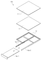
FIG. 1 is a view showing a
The
In other words, since the platform can be formed by assembling the platform units 50 having various shapes and functions, the
1 and 2, the
The
In this case, the above-described horizontal direction and vertical direction are directions for describing the
3, the
That is, the
At this time, it is preferable that the upper
In addition, the upper plate assembly 120 may be formed only on the lower edge of the
Reference numeral 11-1 denotes a long plate member which can be formed on the upper surface of the
4, the
The
The
The column assembly hole 13-1 is formed in the
5, the
That is, the
In this case, it is preferable that the support assembly hole 22-1 is formed to correspond to the position of the column assembly hole 13-1 in order to be assembled using the bolt and nut with the bolt hole 13-1 However, if the assembly can be easily and accurately assembled with the
As described above, since the
Of course, it is preferable that the other end of the column shaft of the
The
As shown in FIG. 5, the
FIG. 6 is a view showing the sliding
When the operation of the object (aircraft body, aircraft body unit body, etc.) (1) for the operation is completed, when the final assembly or subassembly of the aircraft is performed using the platform, When the
Therefore, among the
As described above, the
6, the sliding
The sliding
The sliding
That is, the
7, the
At this time, the folding
The
The
8 is a view showing a
1 to 2 and 8, an
Since the
The
The guide body 31 may have various shapes such as a lattice shape shown in FIG. 8 or a column shape only in a vertical direction, and the guide assembly 32 may be formed in the upper assembly hole 14-1 so that the upper assembly hole 14-1 and the guide assembly hole 32-1 face each other by using bolts and nuts So that the
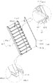
9 is a view showing a moving
Since the
The moving
The moving unit 40 includes a top supporting
The movable support unit 410 is preferably formed obliquely from the ground because it serves to fix and support the foot plate so that the operator can move between the
The
That is, the
Furthermore, the moving
The central moving support unit can be assembled between the upper and lower movable supporting
Of course, in addition to the above-described configuration, the upper
The mobile unit 40 includes a
It is preferable that the footrest unit 42-1 is formed in a plate shape so that an operator or the like can move on the foot, and the
Therefore, as shown in FIG. 9, the
However, it should be understood that the present invention is not limited thereto, and that the
The moving unit 40 includes a moving
Needless to say, it is needless to say that the
1000: Standard platform for aircraft
100: upper plate part 200: support part
300: guide part 400: moving part
10: Top plate unit
11: plate body
12: upper plate assembly part 12-1: upper plate assembly hole
13: Column assembly section 13-1: Column assembly hole
14: upper assembly hole 14-1: upper assembly hole
10a: Sliding
10a-2: Sliding guide 10a-3: Sliding roller
10b: Folding unit
10b-1:
20: Column unit
21: column body
22: Support assembly part 22-1: Support assembly hole
30: guide unit 31: guide body
32: Guide assembly part 32-1: Guide assembly hole
40: mobile unit
41:
41-1: protrusion 41-2: protrusion hole
41-3: Upper moving hole
41a: upper moving support unit
41a-1: Upper moving supporting
41b: a lower movable support unit
41b-1: Lower movable supporting
42: Scaffolding unit
42-1: foot body 42-2: foot assembly hole
43: movement guide unit 43-1: movement guide body
43-2: Movement guide assembly part 43-2a: Movement guide assembly hole
Claims (10)
An upper plate 100 formed by assembling the upper plate units 10 in a horizontal direction,
And a support part (200) formed by vertically assembling the support unit (20) at a lower end of the upper plate part (100).
The upper plate unit 10
And a top plate assembly (12) formed in a direction perpendicular to a lower surface of the plate body (11)
The upper plate assembly (12)
And a top plate assembly hole (12-1) formed at least in the horizontal direction.
The upper plate unit 10
And a column assembly (13) formed horizontally at a lower end of the upper plate assembly (12)
The column assembly (13)
And a column assembly hole (13-1) formed at least in the vertical direction.
The support unit (20)
And a support assembly (22) formed horizontally at both ends of the column shaft of the column body (21)
The support assembly (22)
And a support assembly hole (22-1) formed at least in the horizontal direction.
The upper plate unit 10
A sliding plate 10a-1 slidably inserted in and drawn out from one end of the upper plate assembly 12 in a horizontal direction,
A sliding guide 10a-2 formed horizontally in the upper plate assembly 12 to move the sliding plate 10a-1,
, And a sliding unit (10a) including at least one sliding roller (10a-3) formed in the sliding guide (10a-2).
The upper plate unit 10
A folding plate 10b-1 formed horizontally at one end of the plate body 11 and hinged to be vertically foldable,
The folding plate 10b-1 is horizontally extended from one end of the upper plate assembly 12 so as to be able to support the folding plate 10b-1. And a folding unit (10b) including a folding board support (10b-2) formed to be capable of being drawn in and pulled out.
The upper plate unit 10
And an upper assembly part (14) including an upper assembly hole (14-1) formed at least on the upper surface of the plate body (11).
The standard platform 1000 for an aircraft
And a guide part (300) formed to be assembled with the upper assembly part (14)
The guide part 300
A guide assembly 32 formed in a horizontal direction at a lower end of the guide body 31 so as to be assembled with the upper assembly 14 and at least one Is formed by assembling a guide unit (30) including a guide assembly hole (32-1).
The standard platform for an aircraft (1000)
And a moving part 400 formed to connect the upper plate part 100 and the ground,
The moving unit 400
A movable support unit 41 formed to be assembled with the top plate 100 and the ground,
A plate-shaped pedestal unit 41 formed to be assembled in the horizontal direction to the movable support unit 41,
And a movement guide unit (43) formed so as to be assembled on the upper portion of the mobile support unit (41).
The moving support unit (41)
An upper moving supporting portion 41a-1 including an upper moving supporting hole 41a-2 formed to be assembled with the upper plate assembling portion 12 or the upper assembling portion 14 of the upper plate unit 10 is formed at one end An upper moving support unit 41a,
(41b-1) including a lower movable support hole (41b-2) formed so as to be able to be assembled with the ground, is formed at one end of the lower movable support unit
And the other end of the upper and lower movable support units (41a, 41b) is formed to be assembled.
Priority Applications (1)
| Application Number | Priority Date | Filing Date | Title |
|---|---|---|---|
| KR1020150188122A KR101805401B1 (en) | 2015-12-29 | 2015-12-29 | Standard Platform for Aircraft |
Applications Claiming Priority (1)
| Application Number | Priority Date | Filing Date | Title |
|---|---|---|---|
| KR1020150188122A KR101805401B1 (en) | 2015-12-29 | 2015-12-29 | Standard Platform for Aircraft |
Publications (2)
| Publication Number | Publication Date |
|---|---|
| KR20170078024A true KR20170078024A (en) | 2017-07-07 |
| KR101805401B1 KR101805401B1 (en) | 2018-01-10 |
Family
ID=59353531
Family Applications (1)
| Application Number | Title | Priority Date | Filing Date |
|---|---|---|---|
| KR1020150188122A KR101805401B1 (en) | 2015-12-29 | 2015-12-29 | Standard Platform for Aircraft |
Country Status (1)
| Country | Link |
|---|---|
| KR (1) | KR101805401B1 (en) |
Cited By (3)
| Publication number | Priority date | Publication date | Assignee | Title |
|---|---|---|---|---|
| EP3651004A1 (en) | 2017-06-20 | 2020-05-13 | LG Electronics Inc. | Mobile terminal |
| KR20200067577A (en) | 2018-12-04 | 2020-06-12 | 한국항공우주산업 주식회사 | Smart platform for aircraft |
| KR102591224B1 (en) * | 2023-05-08 | 2023-10-20 | (주)대산이엔지 | Scaffolding with avoidance type space structure |
Families Citing this family (1)
| Publication number | Priority date | Publication date | Assignee | Title |
|---|---|---|---|---|
| US11718426B1 (en) | 2020-05-29 | 2023-08-08 | United Launch Alliance, L.L.C. | Highly adaptable platform |
Family Cites Families (1)
| Publication number | Priority date | Publication date | Assignee | Title |
|---|---|---|---|---|
| US9441382B2 (en) * | 2013-04-15 | 2016-09-13 | Clifford R. Hokanson | Adjustable aircraft maintenance platform for improving efficiency and safety of aircraft maintenance operations |
-
2015
- 2015-12-29 KR KR1020150188122A patent/KR101805401B1/en active IP Right Grant
Cited By (3)
| Publication number | Priority date | Publication date | Assignee | Title |
|---|---|---|---|---|
| EP3651004A1 (en) | 2017-06-20 | 2020-05-13 | LG Electronics Inc. | Mobile terminal |
| KR20200067577A (en) | 2018-12-04 | 2020-06-12 | 한국항공우주산업 주식회사 | Smart platform for aircraft |
| KR102591224B1 (en) * | 2023-05-08 | 2023-10-20 | (주)대산이엔지 | Scaffolding with avoidance type space structure |
Also Published As
| Publication number | Publication date |
|---|---|
| KR101805401B1 (en) | 2018-01-10 |
Similar Documents
| Publication | Publication Date | Title |
|---|---|---|
| KR101805401B1 (en) | Standard Platform for Aircraft | |
| US7510056B2 (en) | Roof railing for an elevator car adapted to be collapsed with a handle actuating all sides at the same time | |
| US10648235B2 (en) | Work stand configurable for different work areas | |
| EP3336037A1 (en) | A system comprising a rotatable work platform | |
| CN106662075B (en) | Assembly system and method for assembling a tower of a wind turbine | |
| KR101629707B1 (en) | Separate Safety Unit of Aerial Work Platforms | |
| CN110573686A (en) | Formwork support device | |
| KR20190127275A (en) | Smart safety scaffold for the maximize to the ease of movement and storage | |
| KR101618703B1 (en) | Slab concrete mold for building | |
| JP2011052474A (en) | Foldable working scaffold | |
| KR101854093B1 (en) | The fit jack of commercial vehicle | |
| KR101564937B1 (en) | Apparatus for installing heavy object and Method for installing heavy object | |
| KR101170097B1 (en) | Fordable Shelf | |
| CN204660035U (en) | A kind of transporation by plane and inspection platform | |
| CN205852653U (en) | Engine flexible divides spelling dolly frock | |
| CN103458644A (en) | Power distribution unit and cabinet with same | |
| CN213865205U (en) | A strain and shake anti-shake formula and cut fork lift platform for unmanned aerial vehicle | |
| JP2012207379A (en) | Structure demolition system | |
| KR20120008547U (en) | Bulk head working stand | |
| KR101820954B1 (en) | Foldable work stage for suspension scaffold | |
| CN102381619B (en) | Counterweight lifting device, counterweight lifting structure and counterweight lifting method | |
| KR200488336Y1 (en) | Disassembly and assembly device for actuator coupling of low pressure turbine | |
| KR101497337B1 (en) | Apparatus for elevating thruster | |
| JP7161164B2 (en) | Workbench | |
| CN214192340U (en) | Maintenance device for regenerator of circulating fluidized bed |
Legal Events
| Date | Code | Title | Description |
|---|---|---|---|
| A201 | Request for examination | ||
| E902 | Notification of reason for refusal | ||
| E90F | Notification of reason for final refusal | ||
| E701 | Decision to grant or registration of patent right |