KR20170077016A - Line roller - Google Patents
Line roller Download PDFInfo
- Publication number
- KR20170077016A KR20170077016A KR1020160105936A KR20160105936A KR20170077016A KR 20170077016 A KR20170077016 A KR 20170077016A KR 1020160105936 A KR1020160105936 A KR 1020160105936A KR 20160105936 A KR20160105936 A KR 20160105936A KR 20170077016 A KR20170077016 A KR 20170077016A
- Authority
- KR
- South Korea
- Prior art keywords
- grease
- holding
- bearing member
- bearing
- line roller
- Prior art date
Links
- 239000004519 grease Substances 0.000 claims abstract description 316
- 239000005871 repellent Substances 0.000 claims abstract description 87
- 238000005096 rolling process Methods 0.000 claims abstract description 12
- XLYOFNOQVPJJNP-UHFFFAOYSA-N water Substances O XLYOFNOQVPJJNP-UHFFFAOYSA-N 0.000 claims description 58
- 230000002940 repellent Effects 0.000 claims description 46
- 238000009987 spinning Methods 0.000 claims description 16
- 230000001050 lubricating effect Effects 0.000 claims description 6
- 238000000034 method Methods 0.000 claims 13
- 230000008878 coupling Effects 0.000 claims 1
- 238000010168 coupling process Methods 0.000 claims 1
- 238000005859 coupling reaction Methods 0.000 claims 1
- 239000013535 sea water Substances 0.000 abstract description 28
- 230000002093 peripheral effect Effects 0.000 abstract description 12
- 230000001105 regulatory effect Effects 0.000 description 30
- 230000007246 mechanism Effects 0.000 description 27
- 230000004048 modification Effects 0.000 description 22
- 238000012986 modification Methods 0.000 description 22
- 230000000295 complement effect Effects 0.000 description 5
- 230000000694 effects Effects 0.000 description 5
- 239000002184 metal Substances 0.000 description 5
- 229920003002 synthetic resin Polymers 0.000 description 5
- 239000000057 synthetic resin Substances 0.000 description 5
- YCKRFDGAMUMZLT-UHFFFAOYSA-N Fluorine atom Chemical compound [F] YCKRFDGAMUMZLT-UHFFFAOYSA-N 0.000 description 3
- 229910052731 fluorine Inorganic materials 0.000 description 3
- 239000011737 fluorine Substances 0.000 description 3
- -1 for example Substances 0.000 description 3
- 239000000463 material Substances 0.000 description 3
- 229920001296 polysiloxane Polymers 0.000 description 3
- 239000002562 thickening agent Substances 0.000 description 3
- KAKZBPTYRLMSJV-UHFFFAOYSA-N Butadiene Chemical compound C=CC=C KAKZBPTYRLMSJV-UHFFFAOYSA-N 0.000 description 2
- XUIMIQQOPSSXEZ-UHFFFAOYSA-N Silicon Chemical compound [Si] XUIMIQQOPSSXEZ-UHFFFAOYSA-N 0.000 description 2
- 230000007547 defect Effects 0.000 description 2
- 230000033001 locomotion Effects 0.000 description 2
- 238000005461 lubrication Methods 0.000 description 2
- 238000004519 manufacturing process Methods 0.000 description 2
- 229920006324 polyoxymethylene Polymers 0.000 description 2
- 229920001343 polytetrafluoroethylene Polymers 0.000 description 2
- 239000004810 polytetrafluoroethylene Substances 0.000 description 2
- 238000007789 sealing Methods 0.000 description 2
- 239000010703 silicon Substances 0.000 description 2
- 229910052710 silicon Inorganic materials 0.000 description 2
- 229920002545 silicone oil Polymers 0.000 description 2
- 229910001220 stainless steel Inorganic materials 0.000 description 2
- 239000010935 stainless steel Substances 0.000 description 2
- NLHHRLWOUZZQLW-UHFFFAOYSA-N Acrylonitrile Chemical compound C=CC#N NLHHRLWOUZZQLW-UHFFFAOYSA-N 0.000 description 1
- 244000043261 Hevea brasiliensis Species 0.000 description 1
- 229920000459 Nitrile rubber Polymers 0.000 description 1
- 229930182556 Polyacetal Natural products 0.000 description 1
- 230000004323 axial length Effects 0.000 description 1
- 229920001577 copolymer Polymers 0.000 description 1
- 238000005520 cutting process Methods 0.000 description 1
- 230000002950 deficient Effects 0.000 description 1
- 230000009545 invasion Effects 0.000 description 1
- JEIPFZHSYJVQDO-UHFFFAOYSA-N iron(III) oxide Inorganic materials O=[Fe]O[Fe]=O JEIPFZHSYJVQDO-UHFFFAOYSA-N 0.000 description 1
- 239000010687 lubricating oil Substances 0.000 description 1
- 230000014759 maintenance of location Effects 0.000 description 1
- 238000000465 moulding Methods 0.000 description 1
- 229920003052 natural elastomer Polymers 0.000 description 1
- 229920001194 natural rubber Polymers 0.000 description 1
- 239000003921 oil Substances 0.000 description 1
- 238000012946 outsourcing Methods 0.000 description 1
- 230000000149 penetrating effect Effects 0.000 description 1
- 230000035515 penetration Effects 0.000 description 1
- 239000010702 perfluoropolyether Substances 0.000 description 1
- 229920005989 resin Polymers 0.000 description 1
- 239000011347 resin Substances 0.000 description 1
- 150000003839 salts Chemical class 0.000 description 1
- 229910021487 silica fume Inorganic materials 0.000 description 1
- 239000000344 soap Substances 0.000 description 1
- 238000007711 solidification Methods 0.000 description 1
- 230000008023 solidification Effects 0.000 description 1
- 229910001256 stainless steel alloy Inorganic materials 0.000 description 1
- 239000000758 substrate Substances 0.000 description 1
- 229920003051 synthetic elastomer Polymers 0.000 description 1
- 239000005061 synthetic rubber Substances 0.000 description 1
- 238000004804 winding Methods 0.000 description 1
Images


Classifications
-
- A—HUMAN NECESSITIES
- A01—AGRICULTURE; FORESTRY; ANIMAL HUSBANDRY; HUNTING; TRAPPING; FISHING
- A01K—ANIMAL HUSBANDRY; CARE OF BIRDS, FISHES, INSECTS; FISHING; REARING OR BREEDING ANIMALS, NOT OTHERWISE PROVIDED FOR; NEW BREEDS OF ANIMALS
- A01K89/00—Reels
- A01K89/01—Reels with pick-up, i.e. with the guiding member rotating and the spool not rotating during normal retrieval of the line
- A01K89/0111—Spool details
-
- A—HUMAN NECESSITIES
- A01—AGRICULTURE; FORESTRY; ANIMAL HUSBANDRY; HUNTING; TRAPPING; FISHING
- A01K—ANIMAL HUSBANDRY; CARE OF BIRDS, FISHES, INSECTS; FISHING; REARING OR BREEDING ANIMALS, NOT OTHERWISE PROVIDED FOR; NEW BREEDS OF ANIMALS
- A01K89/00—Reels
- A01K89/01—Reels with pick-up, i.e. with the guiding member rotating and the spool not rotating during normal retrieval of the line
- A01K89/01121—Frame details
- A01K89/011222—Frame details with lubrication features
-
- A—HUMAN NECESSITIES
- A01—AGRICULTURE; FORESTRY; ANIMAL HUSBANDRY; HUNTING; TRAPPING; FISHING
- A01K—ANIMAL HUSBANDRY; CARE OF BIRDS, FISHES, INSECTS; FISHING; REARING OR BREEDING ANIMALS, NOT OTHERWISE PROVIDED FOR; NEW BREEDS OF ANIMALS
- A01K89/00—Reels
- A01K89/01—Reels with pick-up, i.e. with the guiding member rotating and the spool not rotating during normal retrieval of the line
- A01K89/0108—Pick-up details
-
- A—HUMAN NECESSITIES
- A01—AGRICULTURE; FORESTRY; ANIMAL HUSBANDRY; HUNTING; TRAPPING; FISHING
- A01K—ANIMAL HUSBANDRY; CARE OF BIRDS, FISHES, INSECTS; FISHING; REARING OR BREEDING ANIMALS, NOT OTHERWISE PROVIDED FOR; NEW BREEDS OF ANIMALS
- A01K89/00—Reels
- A01K89/01—Reels with pick-up, i.e. with the guiding member rotating and the spool not rotating during normal retrieval of the line
- A01K89/01121—Frame details
- A01K89/011221—Frame details with line or water shields
-
- A—HUMAN NECESSITIES
- A01—AGRICULTURE; FORESTRY; ANIMAL HUSBANDRY; HUNTING; TRAPPING; FISHING
- A01K—ANIMAL HUSBANDRY; CARE OF BIRDS, FISHES, INSECTS; FISHING; REARING OR BREEDING ANIMALS, NOT OTHERWISE PROVIDED FOR; NEW BREEDS OF ANIMALS
- A01K89/00—Reels
- A01K89/01—Reels with pick-up, i.e. with the guiding member rotating and the spool not rotating during normal retrieval of the line
- A01K89/01121—Frame details
- A01K89/011223—Frame details with bearing features
-
- F—MECHANICAL ENGINEERING; LIGHTING; HEATING; WEAPONS; BLASTING
- F16—ENGINEERING ELEMENTS AND UNITS; GENERAL MEASURES FOR PRODUCING AND MAINTAINING EFFECTIVE FUNCTIONING OF MACHINES OR INSTALLATIONS; THERMAL INSULATION IN GENERAL
- F16C—SHAFTS; FLEXIBLE SHAFTS; ELEMENTS OR CRANKSHAFT MECHANISMS; ROTARY BODIES OTHER THAN GEARING ELEMENTS; BEARINGS
- F16C19/00—Bearings with rolling contact, for exclusively rotary movement
- F16C19/02—Bearings with rolling contact, for exclusively rotary movement with bearing balls essentially of the same size in one or more circular rows
- F16C19/04—Bearings with rolling contact, for exclusively rotary movement with bearing balls essentially of the same size in one or more circular rows for radial load mainly
- F16C19/06—Bearings with rolling contact, for exclusively rotary movement with bearing balls essentially of the same size in one or more circular rows for radial load mainly with a single row or balls
Abstract
[과제] 해수 등이 내부에 침입하기 어려운 구조의 베어링 부재를 가지는 라인 롤러를 제공한다.
[해결 수단] 라인 롤러(3)는, 낚싯줄을 안내하는 가이드면(61)을 외주(外周)에 가지는 원통상(圓筒狀)의 안내 부재(6)와, 안내 부재(6)의 내주면(內周面)을 회전 가능하게 지지하는 베어링 부재(4)와, 베어링 부재(4)를 지지하는 지지 부재를 구비하고, 베어링 부재(4)는, 지지 부재에 지지된 내륜(內輪)(41)과, 안내 부재(6)와 일체로 되어 회전하는 외륜(外輪)(42)과, 내륜(41)과 외륜(42)과의 사이에 배치된 전동체(43)와, 내륜(41)과 외륜(42)과의 사이에서 발수성(撥水性) 그리스(grease)(10)를 보지(保持)하는 그리스 보지부를 가진다.[PROBLEMS] To provide a line roller having a bearing member having a structure in which seawater or the like is hardly penetrated into the inside.
The line roller 3 includes a cylindrical guide member 6 having a guide surface 61 for guiding a fishing line on the outer periphery thereof and an inner peripheral surface of the guide member 6 And a bearing member 4 for supporting the bearing member 4. The bearing member 4 has an inner ring 41 supported by a support member A rolling member 43 disposed between the inner ring 41 and the outer ring 42 and a rolling member 43 disposed between the inner ring 41 and the outer ring 42, And a grease holding portion for holding a water-repellent grease 10 between the outer ring and the outer ring.
Description
본 발명은, 낚시용의 스피닝 릴의 라인 롤러에 관한 것이다.The present invention relates to a line roller of a spinning reel for fishing.
낚시용의 스피닝 릴은, 스풀과, 한 쌍의 로터 암을 가지는 로터와, 한 쌍의 로터 암의 선단부(先端部)에 요동(搖動) 가능하게 장착된 낚싯줄 안내 기구(이른바 베일 암)를 구비하고 있다(예를 들어 특허 문헌 1). 낚싯줄 안내 기구는, 낚싯줄을 스풀로 안내하기 위한 기구이다. 이 낚싯줄 안내 기구는, 베일과, 베일의 양 단부(端部)를 지지하는 한 쌍의 베일 지지 부재와, 라인 롤러를 가지고 있다.A spinning reel for fishing includes a spool, a rotor having a pair of rotor arms, and a fishing line guide mechanism (so-called bail arm) mounted so as to be able to swing on a tip end portion of a pair of rotor arms (For example, Patent Document 1). The fishing line guide mechanism is a mechanism for guiding the fishing line to the spool. The fishing line guide mechanism has a bail, a pair of bail support members for supporting both ends of the bail, and a line roller.
라인 롤러는 일반적으로, 안내 부재와 베어링 등의 베어링 부재를 가지고 있다. 안내 부재는, 베어링 부재에 회전 가능하게 장착되어 있다. 라인 롤러는 해수 등에 접하기 쉬운 환경에서 사용되기 때문에, 베어링 부재의 내부에 해수 등이 침입하기 쉽다. 해수 등이 베어링 부재 내부에 침입하면 염분의 고화(固化)나 녹이 발생하여 베어링 부재의 기능이 저하한다. 그래서 낚시용 릴의 구름 베어링 내부에 해수 등이 침입하는 것을 억제하기 위하여, 베어링의 내부에 발수성(撥水性) 그리스(grease)를 봉입한 것이 있다(예를 들어 특허 문헌 2). 또한, 구름 베어링에 접촉 또는 비접촉의 밀봉 구조를 설치하고, 윤활용 그리스를 봉입한 것이 있다(예를 들어 특허 문헌 3).The line roller generally has a bearing member such as a guide member and a bearing. The guide member is rotatably mounted on the bearing member. Since the line roller is used in an environment where it is easy to contact seawater or the like, seawater or the like easily penetrates into the bearing member. When sea water penetrates into the bearing member, solidification or rust of the salt occurs and the function of the bearing member is deteriorated. In order to prevent seawater and the like from entering into the rolling bearing of the fishing reel, a water-repellent grease is sealed inside the bearing (for example, Patent Document 2). Further, a rolling bearing is provided with a sealing structure in contact with or non-contact with the rolling bearing, and lubricating grease is enclosed (see, for example, Patent Document 3).
특허 문헌 2에 개시된 베어링 부재에는, 발수성 그리스가 외부로 유출하는 것을 방지하기 위하여, 베어링 부재의 양측에 실(seal)이 설치되어 있다. 그러나, 실의 단부와 베어링 부재와의 사이에는 간극(間隙)이 있기 때문에, 라인 롤러에 가해지는 원심력 등에 의하여 그 간극으로부터 발수성 그리스가 유출할 가능성이 있다. 일단 발수성 그리스가 유출하여 버리면, 베어링 부재의 내부에 해수 등이 용이하게 침입한다.In the bearing member disclosed in
특허 문헌 3에 개시된 베어링에는, 이물의 침입을 방지하기 위하여(방진성(防塵性)의 향상을 도모하기 위하여), 밀봉판이 대립되는 평면끼리로 요철상(凹凸狀)의 래버린스(labyrinth)가 구성되어 있다. 그러나, 이와 같은 베어링에서는, 이물의 침입을 방지하는 것은 일정 정도 가능하지만, 윤활용 그리스를 이용하기 위하여 해수 등에 대하여는 방수성 등이 충분하지 않았다. 그 때문에, 베어링 부재의 내부에 해수 등이 용이하게 침입하지 않는 베어링 부재를 가지는 라인 롤러가 바람직하다.The bearing disclosed in
본 발명은 상기와 같은 문제를 해결하기 위하여 이루어진 것이고, 해수 등이 내부에 침입하기 어려운 구조의 베어링 부재를 가지는 라인 롤러를 제공하는 것을 목적으로 한다.SUMMARY OF THE INVENTION It is an object of the present invention to provide a line roller having a bearing member having a structure in which seawater or the like hardly invades the inside.
(1) 본 발명에 관련되는 라인 롤러는,(1) In the line roller according to the present invention,
낚시용 스피닝 릴의 스풀로 낚싯줄을 안내하기 위한 라인 롤러이고,A line roller for guiding a fishing line by a spool of a fishing spinning reel,
낚싯줄을 안내하는 가이드면을 외주(外周)에 가지는 원통상(圓筒狀)의 안내 부재와,A cylindrical guide member having a guide surface for guiding a fishing line on an outer circumference thereof,
상기 안내 부재의 내주면(內周面)을 회전 가능하게 지지하는 베어링 부재와,A bearing member rotatably supporting an inner circumferential surface of the guide member,
상기 베어링 부재를 지지하는 지지 부재를 구비하고,And a support member for supporting the bearing member,
상기 베어링 부재는, 상기 지지 부재에 지지된 내륜(內輪)과, 상기 안내 부재와 일체로 되어 회전하는 외륜(外輪)과, 상기 내륜과 상기 외륜과의 사이에 배치된 전동체와, 상기 내륜과 상기 외륜과의 사이에서 발수성 그리스를 보지(保持)하는 그리스 보지부를 가지고 있다.Wherein the bearing member includes an inner ring supported by the support member, an outer ring rotated integrally with the guide member, a rolling member disposed between the inner ring and the outer ring, And a grease holding portion for holding a water repellent grease between the outer ring and the outer ring.
(2) 바람직하게는, 상기 그리스 보지부는, 상기 내륜으로부터 직경 외측(外側) 방향으로 돌출하는 제1 그리스 보지부 형성부와, 상기 외륜으로부터 직경 내측(內側) 방향으로 돌출하고, 상기 제1 그리스 보지부 형성부의 측면과 대향하는 측면을 가지는 제2 그리스 보지부 형성부를 가지고, 상기 제1 그리스 보지부 형성부의 측면과 상기 제2 그리스 보지부 형성부의 측면과의 사이에 상기 발수성 그리스가 보지되어 있다.(2) Preferably, the grease holding portion includes: a first grease holding portion-forming portion that protrudes in a radially outward (outward) direction from the inner ring; and a second grease holding portion protruding inward from the outer ring in a radial direction, The water repellent grease is held between the side surface of the first grease holding portion forming portion and the side surface of the second grease holding portion forming portion, the second grease holding portion forming portion having a side opposite to the side surface of the holding portion forming portion .
(3) 바람직하게는, 상기 그리스 보지부는, 상기 제1 그리스 보지부 형성부의 측면과 상기 제2 그리스 보지부 형성부의 측면이 상보적으로 굴곡하여 대향한다.(3) Preferably, the side surface of the first grease holding portion forming portion and the side surface of the second grease holding portion forming portion complementarily bend and oppose the grease holding portion.
(4) 바람직하게는, 상기 그리스 보지부는, 상기 제2 그리스 보지부 형성부가 오목부를 가지고, 상기 제1 그리스 보지부 형성부가 상기 오목부에 간극을 가지고 삽입되고, 상기 간극에 상기 발수성 그리스가 보지되어 있다.(4) Preferably, the grease holding portion has a concave portion in the second grease holding portion forming portion, the first grease holding portion forming portion is inserted with a gap in the concave portion, and the water- .
(5) 바람직하게는, 라인 롤러는 상기 안내 부재와 상기 외륜과의 사이에, 상기 안내 부재와 상기 외륜을 결합하는 보지 부재를 더 구비하고, 상기 보지 부재의 일부가 상기 제2 그리스 보지부 형성부를 겸한다.(5) Preferably, the line roller further includes a retaining member for retaining the guide member and the outer ring between the guide member and the outer ring, and a part of the retaining member is engaged with the second grease retaining portion It also serves as wealth.
(6) 바람직하게는, 라인 롤러는 상기 베어링 부재로부터 상기 안내 부재까지 통하는 공간을 구성하는 것과 함께 상기 공간에 발수성 그리스를 보지한 외부 그리스 보지부를 더 구비한다.(6) Preferably, the line roller further comprises an external grease retaining portion which constitutes a space communicating from the bearing member to the guide member and in which the water-repellent grease is held in the space.
(7) 바람직하게는, 상기 외부 그리스 보지부는, 상기 안내 부재와 상기 지지 부재와의 사이에 배치된 탄성 부재로 이루어지는 실 부재를 포함한다.(7) Preferably, the external grease holding portion includes a seal member formed of an elastic member disposed between the guide member and the support member.
(8) 바람직하게는, 상기 실 부재는, 상기 안내 부재 및 상기 지지 부재 중 어느 일방(一方)의 부재에 고정되는 고정부와, 상기 고정부로부터 타방(他方)의 부재를 향하여 연재(延在)하고, 선단부의 두께가 상기 고정부의 두께보다도 얇게 형성된 립부를 구비한다.(8) Preferably, the seal member includes a fixed portion fixed to one of the guide member and the support member, and a plurality of extended portions extending from the fixed portion toward the other member And a lip portion having a thickness of the distal end portion smaller than a thickness of the fixed portion.
(9) 바람직하게는, 상기 외부 그리스 보지부는, 상기 베어링 부재의 회전축 방향 또는 경(徑)방향으로 돌출한 환상(環狀) 볼록부를 가지는 제1 환상 볼록 부재와, 상기 환상 볼록부에 대향하는 방향으로 인접하여 돌출한 환상 볼록부를 가지는 제2 환상 볼록 부재를 포함한다.(9) Preferably, the outer grease retaining portion includes: a first annular convex member having an annular convex portion protruding in a direction of a rotation axis or a radial direction of the bearing member; And a second annular convex member having an annular convex portion protruding adjacent to the first annular convex member.
(10) 바람직하게는, 상기 외부 그리스 보지부는, 상기 베어링 부재의 회전축 방향 또는 경방향으로 돌출한 환상 볼록부를 가지는 환상 볼록 부재와, 상기 환상 볼록부와 대향하는, 상기 환상 볼록부와 상보적으로 함요(陷凹)한 환상 오목부를 가지는 환상 오목 부재를 포함한다.(10) Preferably, the external grease retaining portion includes: an annular convex member having an annular convex portion protruding in a direction of a rotational axis of the bearing member or in a radial direction; and an annular convex member, which is complementary to the annular convex portion, And includes an annular concave member having an annular concave portion.
(11) 바람직하게는, 상기 발수성 그리스는, 상기 베어링 부재의 회전 지지축 방향의 일방의 외단면(外端面)과 상기 안내 부재까지 통하는 상기 공간의 적어도 일부에 보지되어 있다.(11) Preferably, the water-repellent grease is held on at least one part of an outer end face of the bearing member in the direction of the rotation support axis and the space leading to the guide member.
(12) 바람직하게는, 상기 발수성 그리스가, 상기 베어링 부재의 내부에 충전(充塡)되어 있다.(12) Preferably, the water repellent grease is filled in the bearing member.
(13) 바람직하게는, 상기 발수성 그리스와 다른 윤활용 그리스가, 상기 베어링 부재의 내부에 충전되어 있다.(13) Preferably, the lubricating grease different from the water-repellent grease is filled in the bearing member.
(14) 바람직하게는, 라인 롤러는 상기 베어링 부재로부터 상기 안내 부재까지 통하는 공간을 구성하는 것과 함께 상기 공간에 발수성 그리스를 보지한 외부 그리스 보지부를 구비하고, 상기 보지 부재의 일부가 상기 외부 그리스 보지부의 일부를 구성한다.(14) Preferably, the line roller comprises an outer grease holding portion which constitutes a space communicating from the bearing member to the guide member, and which has a water-repellent grease held in the space, and a part of the holding member, Constitute part of the Department.
본 발명에 의하면, 해수 등이 내부에 침입하기 어려운 구조의 베어링 부재를 가지는 라인 롤러를 제공할 수 있다.According to the present invention, it is possible to provide a line roller having a bearing member having a structure in which seawater or the like hardly invades the inside.
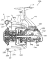
도 1은 본 발명의 실시예 1에 관련되는 낚시용 스피닝 릴의 전체도이다.
도 2는 도 1에 도시하는 낚시용 스피닝 릴의 단면도이다.
도 3은 도 1에 도시하는 낚시용 스피닝 릴의 정면도이다.
도 4는 도 1에 도시하는 낚시용 스피닝 릴의 낚싯줄 안내 기구의 부분 확대도이다.
도 5는 도 1에 도시하는 낚시용 스피닝 릴의 낚싯줄 안내 기구의 부분 단면도이다.
도 6은 도 1에 도시하는 낚시용 스피닝 릴의 라인 롤러의 단면도이다.
도 7의 (a)는 본 발명의 변형예 1에 관련되는 베어링 부재의 단면도, (b)는 변형예 2에 관련되는 베어링 부재의 단면도이다.
도 8의 (a)는 본 발명의 변형예 3에 관련되는 베어링 부재의 단면도, (b)는 변형예 4에 관련되는 베어링 부재의 단면도이다.
도 9는 본 발명의 실시예 2에 관련되는 낚싯줄 안내 기구의 부분 단면도이다.
도 10은 실시예 2에 관련되는 라인 롤러의 확대 단면도이다.
도 11의 (a)는 본 발명의 실시예 3에 관련되는 낚싯줄 안내 기구의 부분 단면도, (b)는 그 라인 롤러의 확대 단면도이다.
도 12는 본 발명의 변형예 5에 관련되는 라인 롤러의 확대 단면도이다.
도 13은 본 발명의 변형예 6에 관련되는 라인 롤러의 확대 단면도이다.
도 14는 본 발명의 변형예 8에 관련되는 라인 롤러의 확대 단면도이다.
도 15는 본 발명의 변형예 9에 관련되는 라인 롤러의 확대 단면도이다.1 is an overall view of a fishing spinning reel according to a first embodiment of the present invention.
2 is a sectional view of the spinning reel for fishing shown in Fig.
Fig. 3 is a front view of the fishing spinning reel shown in Fig. 1. Fig.
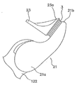
Fig. 4 is a partially enlarged view of the fishing line guide mechanism of the spinning reel for fishing shown in Fig. 1. Fig.
5 is a partial cross-sectional view of the fishing line guide mechanism of the fishing spinning reel shown in Fig.
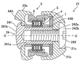
6 is a sectional view of the line roller of the fishing spinning reel shown in Fig.
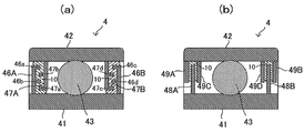
FIG. 7A is a cross-sectional view of a bearing member according to a first modification of the present invention, and FIG. 7B is a cross-sectional view of a bearing member according to a second modification.
FIG. 8A is a cross-sectional view of a bearing member according to a third modification of the present invention, and FIG. 8B is a cross-sectional view of a bearing member according to a fourth modification.
9 is a partial cross-sectional view of a fishing line guide mechanism according to a second embodiment of the present invention.
10 is an enlarged sectional view of the line roller according to the second embodiment.
Fig. 11 (a) is a partial cross-sectional view of a fishing line guide mechanism according to a third embodiment of the present invention, and Fig. 11 (b) is an enlarged sectional view of the line roller.
12 is an enlarged cross-sectional view of a line roller according to a fifth modification of the present invention.
13 is an enlarged cross-sectional view of a line roller according to a sixth modification of the present invention.
14 is an enlarged cross-sectional view of a line roller according to a
15 is an enlarged sectional view of a line roller according to a ninth modification of the present invention.
(실시예 1)(Example 1)
본 발명의 실시예 1에 관련되는 낚시용 스피닝 릴과 그것에 이용하는 라인 롤러에 관하여 도면을 참조하면서 설명한다. 덧붙여, 이하의 설명에 있어서, 「전(前)」이란 낚싯줄을 방출하는 방향을 나타내고, 구체적으로는 도 1 및 도 2의 왼쪽이 「전」이다. 또한, 각 부재의 재질에 관하여도 예시의 것으로 한정되지 않고, 필요한 기능과 내구성을 가지는 공지의 재료를 적의(適宜) 이용할 수 있다.A spinning reel for fishing and a line roller used therefor according to Embodiment 1 of the present invention will be described with reference to the drawings. Incidentally, in the following description, " front " indicates the direction in which the fishing line is emitted, and specifically, the left side of Figs. 1 and 2 is " before ". The material of each member is not limited to the example, and a known material having necessary functions and durability can be used appropriately.
도 1에 도시하는 바와 같이, 낚시용 스피닝 릴(100)은, 릴 본체(110), 로터(120), 스풀(130), 핸들(140), 및 낚싯줄 안내 기구(2)를 구비하고 있다. 또한, 도 2에 도시하는 바와 같이, 낚시용 스피닝 릴(100)은, 구동 기구(150), 오실레이팅(oscillating) 기구(160), 피니언 기어(170), 및 스풀축(180)을 더 구비하고 있다. 1, the
도 1에 도시하는 바와 같이, 릴 본체(110)는, 케이스부(111)와, 덮개부(112)를 가지고 있다. 덮개부(112)는, 케이스부(111)에 대하여 떼어내기 가능하다. 또한, 케이스부(111)는, 전후 방향으로 연장되는 장착부(113)를 가지고 있다. 장착부(113)는, 낚싯대에 장착되는 부분이다.As shown in Fig. 1, the
도 2에 도시하는 바와 같이, 릴 본체(110)는, 케이스부(111)와 덮개부(112)에 의하여 획정(劃定)되는 내부 공간을 가지고 있고, 내부 공간 내에 여러 가지의 기구를 수용하고 있다. 상세하게는, 구동 기구(150), 및 오실레이팅 기구(160)가 릴 본체(110) 내에 수용되어 있다.2, the
구동 기구(150)는, 구동축(151) 및 구동 기어(152)를 구비하고 있다. 구동축(151)은, 핸들축(141)과 연결되어 있고, 핸들축(141)과 일체적으로 회전한다.The
구동 기어(152)는 구동축(151)에 연결되어 있고, 구동축(151)과 일체적으로 회전한다. 구동 기어(152)는, 페이스 기어이고, 피니언 기어(170)의 기어부(171)와 맞물려 있다. 릴 본체(110)의 측면에 장착된 핸들(140)을 회전시키는 것에 의하여, 구동축(151) 및 구동 기어(152)가 회전하고, 피니언 기어(170)도 회전한다.The
피니언 기어(170)는, 릴 본체(110)에 설치되어 있다. 상세하게는, 피니언 기어(170)는, 릴 본체(110) 내로부터 전방(前方)으로 연장되어 있다. 피니언 기어(170)는, 스풀축(180) 둘레에 회전 가능하게 배치되어 있다. 피니언 기어(170)는 통상(筒狀)으로 형성되어 있고, 피니언 기어(170)의 내부에서 스풀축(180)이 연장되어 있다. 덧붙여, 피니언 기어(170)는 복수의 베어링 부재를 통하여 릴 본체(110)에 지지되어 있다.The
스풀축(180)은, 릴 본체(110) 내로부터 전방으로 연장되어 있다. 스풀축(180)은, 핸들(140)을 회전시키는 것에 의하여, 전후 방향으로 왕복 이동한다. 상세하게는, 핸들(140)의 회전이, 구동 기어(152)를 통하여, 피니언 기어(170)를 회전시킨다. 이 피니언 기어(170)의 회전에 수반하여, 오실레이팅 기구(160)가 스풀축(180)을 전후 방향으로 왕복 이동시킨다.The
스풀(130)은, 낚싯줄을이 감기는 부재이다. 스풀(130)은, 스풀축(180)의 선단부에 지지되어 있다. 스풀(130)은, 스풀축(180)과 일체적으로 전후 방향으로 왕복 이동한다.The
로터(120)는, 스풀(130)에 낚싯줄을 감기 위한 부재이다. 로터(120)는, 피니언 기어(170)의 전부(前部)에 고정되어 있고, 피니언 기어(170)와 일체적으로 회전한다. 즉, 로터(120)는 피니언 기어(170)와 상대 회전 불가능하다.The
로터(120)는, 로터 본체부(121)와, 제1 로터 암(122)과, 제2 로터 암(123)을 구비하고 있다. 로터 본체부(121)는, 원통상이다. 제1 로터 암(122) 및 제2 로터 암(123)은, 로터 본체부(121)의 외주면(外周面)으로부터 전방을 향하여 연장되어 있다. 제1 로터 암(122)과 제2 로터 암(123)은, 로터 본체부(121)의 둘레 방향에 있어서, 반대 측의 위치에 배치되어 있다.The
도 3은, 스피닝 릴의 정면도이다. 도 1 ~ 도 3에 도시하는 바와 같이, 낚싯줄 안내 기구(2)는, 스풀(130)로 낚싯줄을 안내하기 위한 기구이다. 낚싯줄 안내 기구(2)는, 제1 로터 암(122) 및 제2 로터 암(123)의 선단부에 취부(取付)되어 있다.3 is a front view of the spinning reel. As shown in Figs. 1 to 3, the fishing
낚싯줄 안내 기구(2)는, 줄 안내 자세와 줄 개방 자세를 취하도록, 요동 가능하게 장착되어 있다. 이 낚싯줄 안내 기구(2)는, 제1 베일 지지 부재(21)와, 제2 베일 지지 부재(22)와, 베일(23)과, 지지축(지지 부재)(24)과, 라인 롤러(3)를 구비하고 있다.The fishing line guide mechanism (2) is mounted so as to swing so as to take a line-guiding posture and a line-releasing posture. The fishing
제1 베일 지지 부재(21)는, 제1 로터 암(122)에 요동 가능하게 장착되어 있다. 상세하게는, 제1 베일 지지 부재(21)는, 제1 로터 암(122)의 선단부의 외측에 요동 가능하게 장착되어 있다.The first
제2 베일 지지 부재(22)는, 제2 로터 암(123)에 요동 가능하게 장착되어 있다. 상세하게는, 제2 베일 지지 부재(22)는, 제2 로터 암(123)의 선단부의 외측에 요동 가능하게 장착되어 있다.The second
도 4는 낚싯줄 안내 기구(2)의 부분 확대도이다. 도 4에 도시하는 바와 같이, 제1 베일 지지 부재(21)는, 제1 단부(21a)와 제2 단부(21b)를 가진다. 제1 단부(21a)는, 제1 로터 암(122)에 요동 가능하게 장착된다. 제1 베일 지지 부재(21)의 제2 단부(21b)는, 지지축(24)(도 5 참조)을 통하여, 베일(23)의 제1 단부(23a)를 지지한다.Fig. 4 is a partially enlarged view of the fishing
도 1 및 도 2에 도시하는 바와 같이, 제2 베일 지지 부재(22)는, 제1 단부(22a)와 제2 단부(22b)를 가진다. 제1 단부(22a)는, 제2 로터 암(123)에 요동 가능하게 장착된다. 제2 단부(22b)는, 베일(23)의 제2 단부(23b)를 지지한다.As shown in Figs. 1 and 2, the second
도 3에 도시하는 바와 같이, 베일(23)은, 대략 U자 형상의 스테인리스 합금제의 부재이다. 베일(23)은, 스풀(130)의 외주면을 따라 외방(外方)으로 볼록하게 되도록 만곡하여 있다. 이 베일(23)은, 제1 단부에 커버부(23a)를 가지고 있다.As shown in Fig. 3, the
이 커버부(23a)는, 지지축(24)을 통하여, 제1 베일 지지 부재(21)에 지지되어 있다. 또한, 베일(23)의 제2 단부(23b)는, 제2 베일 지지 부재(22)에 지지되어 있다. 낚싯줄 안내 기구(2)가 줄 개방 자세로부터 줄 안내 자세로 복귀하였을 때에, 베일(23)은, 낚싯줄을 커버부(23a)를 통하여 라인 롤러(3)로 이끈다. 라인 롤러(3)는, 낚시용 스피닝 릴(100)의 스풀(130)로 낚싯줄을 안내하기 위한 부재이다.The
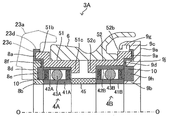
도 5는 라인 롤러(3)를 포함하는 낚싯줄 안내 기구(2)의 부분 단면도이다. 라인 롤러(3)는, 부동(不動)의 지지축(24)에 대하여, 안내 부재(6)가 보지 부재(5)와 함께 지지축(24)의 둘레를 베어링 부재(4)에 의하여 회전 가능하게 지지되어 있다. 낚싯줄은, 회전하는 안내 부재(6)에 의하여 스풀(130)로 안내된다. 덧붙여, 이하의 설명에 있어서, 축 방향이란, 라인 롤러(3)(베어링 부재(4))의 회전축(O)이 연장되는 방향을 의미한다. 즉, 지지축(24)이 연장되는 방향을 의미하고, 도 5에서는 좌우 방향이 축 방향으로 된다. 또한, 경방향이란, 회전축(O)을 중심으로 한 원의 경방향을 의미한다. 또한, 둘레 방향이란, 회전축(O)을 중심으로 한 원의 둘레 방향을 의미한다.5 is a partial cross-sectional view of the fishing
도 5에 도시하는 바와 같이, 제1 베일 지지 부재(21)의 제2 단부(21b)에는 관통공(21c)이 형성되어 있다. 관통공(21c)은, 단붙이의 관통공이다. 이 관통공(21c)에는, 지지축(24)이 관통하고 있다.5, a through
지지축(24)은, 제1 베일 지지 부재(21)와 베일(23)의 커버부(23a)와의 사이에서 연장된다. 지지축(24)은, 통상부(241)와 볼트부(242)를 포함한다. 통상부(241)는, 축부(241a)와 머리부(241b)를 가지고 있다. 축부(241a)는, 원통상이고, 내주면에 암나사부가 형성되어 있다. 머리부(241b)는, 축부(241a)보다도 직경이 크다. 이 머리부(241b)가 커버부(23a)와 당접(當接)하는 것에 의하여, 통상부(241)의 축 방향의 이동이 규제된다.The
볼트부(242)는, 축부(242a)와 머리부(242b)를 가진다. 축부(242a)는, 원기둥 형상이고, 외주면에 수나사부가 형성되어 있다. 이 때문에, 볼트부(242)는, 통상부(241)에 나합(螺合)한다. 머리부(242b)는, 축부(242a)보다도 직경이 크다. 이 머리부(242b)가 제1 베일 지지 부재(21)의 제2 단부(21b)와 당접하는 것에 의하여, 볼트부(242)의 축 방향의 이동이 규제된다.The
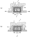
도 5에 도시하는 바와 같이, 라인 롤러(3)는, 베어링 부재(4)와, 보지 부재(칼라(collar) 부재)(5)와, 안내 부재(6)를 구비한다. 또한, 라인 롤러(3)는, 규제 부재(44A), 규제 부재(44B), 규제 부재(7)를 구비한다. 덧붙여, 라인 롤러(3)는 축(O)을 중심으로 하는 원환상(圓環狀)으로 형성되어 있고, 도 5와 같이 축(O)에 평행한 단면도에서는 축(O)에 대하여 상하 대칭이기 때문에, 도 6 이하에서는 축(O)의 상반분(上半分)에 부호를 붙여 설명한다. 또한 도면의 우방향 또는 좌방향을 축 외측 방향이라고 하는 일이 있다. 이하의 단면도에 있어서 마찬가지이다.5, the
베어링 부재(4)는, 도 5의 좌방으로부터 규제 부재(44A)가 당접하고, 도 5의 우방으로부터 규제 부재(44B)가 당접하고 있다. 규제 부재(44B)에는 한층 더 우방으로부터 규제 부재(7)가 당접하고 있다. 이렇게 하여 베어링 부재(4)는, 규제 부재(44A), 규제 부재(44B), 규제 부재(7)에 의하여 그 위치가 규제되어 있다.5, the regulating
도 6에 도시하는 바와 같이, 베어링 부재(4)는, 내륜(41), 외륜(42), 및 복수의 전동체(43)를 가지고 있고, 내륜(41), 외륜(42) 및 복수의 전동체(43)에는, 적도(適度)로 윤활유(윤활 그리스)가 도포되어 있고, 서로 활동(滑動)하고, 회전 지지하도록 구성되어 있다. 내륜(41)은, 원통상이다. 지지축(24)은, 내륜(41)에 감합(嵌合)하여 내륜(41)을 고정 지지하고 있다. 이 때문에, 내륜(41)은, 지지축(24)에 대하여 회전하지 않는다.6, the bearing
외륜(42)은, 원통상이고, 내륜(41)보다도 직경이 크다. 외륜(42)은, 내륜(41)의 경방향 외측에 배치되어 있다. 각 전동체(43)는, 내륜(41)과 외륜(42)과의 사이에 배치되어 있다. 각 전동체(43)는, 둘레 방향에 있어서 서로 간격을 두고 배치되어 있다. 내륜(41) 및 외륜(42)은, 금속, 예를 들어, 스테인리스강에 의하여 형성되어 있다. 외륜과 안내 부재(6)와는 보지 부재(5)를 통하여 결합되어 있다.The
보지 부재(칼라 부재)(5)는, 축 방향으로 나란히 놓인 제1 보지 부재(51) 및 제2 보지 부재(52)를 포함하고 있다. 제1 보지 부재(51)와 제2 보지 부재(52)는, 서로 다른 부재이다. 제1 보지 부재(51)가 제1 어깨부(51a)를 가지고, 제2 보지 부재(52)가 제2 어깨부(52a)를 가진다. 보지 부재(5), 즉, 제1 보지 부재(51) 및 제2 보지 부재(52)는, 합성 수지제인 것이 바람직하다. 특별히 한정되는 것은 아니지만, 예를 들어, 제1 보지 부재(51) 및 제2 보지 부재(52)는, POM(폴리아세탈) 수지에 의하여 형성된다.The holding member (collar member) 5 includes a first holding
보지 부재(5)는, 외륜(42)의 외주와 양 단부에 당접하고 있다. 구체적으로는, 보지 부재(5)의 제1 어깨부(51a)와 제2 어깨부(52a)는, 경방향으로 평판상(平板狀)으로 형성되고, 제1 어깨부(51a)의 내주(內周)는, 외륜(42)의 제1 단부(42a)와 당접하고, 제2 어깨부(52a)의 내주는 외륜(42)의 제2 단부(42b)와 당접한다.The holding
제1 보지 부재(51)와 제2 보지 부재(52)를 베어링 부재(4)에 장착하였을 때, 제1 보지 부재(51)와 제2 보지 부재(52)의 내주면은, 베어링 부재(4)의 외륜(42)의 외주면과 계합(係合)하고, 제1 보지 부재(51)와 제2 보지 부재(52)는 외륜(42)과 일체적으로 회전한다. 안내 부재(6)는 보지 부재(5)와 결합되어 있기 때문에, 안내 부재(6)는 보지 부재(5) 및 외륜(42)과 일체적으로 회전한다.When the first holding
이와 같이, 안내 부재(6)는 베어링 부재(4)의 둘레를 회전한다. 그 때문에, 베어링 부재(4)의 주위에는, 베어링 부재(4)로부터 안내 부재(6)(의 외주부, 라인 롤러(3)의 외부 공간)까지 통하는 공간이 있다. 이 공간을 지나 해수 등이 베어링 부재(4)에 도달하고, 베어링 부재(4)의 내부에 침입하면, 베어링 부재(4)의 기능이 저하한다. 그 때문에, 해수 등이 베어링 부재(4)의 내부에 침입하기 어렵도록, 베어링 부재(4)는 내륜(41)과 외륜(42)과의 사이에 발수성 그리스(10)를 보지하는 그리스 보지부를 가지고 있다.In this way, the
도 6에 도시하는 바와 같이, 내륜(41)의 일방의 단부(도 6의 좌측 단부)에 있어서, 내륜(41)의 외주면으로부터 제1 그리스 보지부 형성부(46A)가 직경 외측 방향으로 원환상으로 돌출하여 있다. 제1 그리스 보지부 형성부(46A)의 돌출 높이는, 외륜(42)의 내주면에 당접하지 않고 간극을 가지는 높이이다. 제1 그리스 보지부 형성부(46A)에는, 선단부와 중간부에, 축 외측 방향으로 돌출한 원환상의 볼록부(46a), 볼록부(46b)가 각각 형성되어 있다. 볼록부(46a), 볼록부(46b)는, 제1 그리스 보지부 형성부(46A)에 비하여 경방향의 폭이 좁은 환상이다.6, the first grease retaining
또한, 외륜(42)의 일방의 단부에 있어서, 외륜(42)의 내주면으로부터 제2 그리스 보지부 형성부(47A)가 직경 내측 방향으로 원환상으로 돌출하여 있다. 제2 그리스 보지부 형성부(47A)의 돌출 높이는, 내륜(41)의 외주면에 당접하지 않고 간극을 가지는 높이이다. 제2 그리스 보지부 형성부(47A)는, 제1 그리스 보지부 형성부(46A)보다도 축 외측 방향에 위치하도록 배치되어 있다. 제2 그리스 보지부 형성부(47A)에는, 선단부와 중간부에, 축 내측 방향으로 돌출한 원환상의 볼록부(47a), 볼록부(47b)가 각각 형성되어 있다. 볼록부(47a), 볼록부(47b)는, 제2 그리스 보지부 형성부(47A)에 비하여 경방향의 폭이 좁은 환상이다. 제1 그리스 보지부 형성부(46A)와 제2 그리스 보지부 형성부(47A)는, 금속 또는 합성 수지로 형성된다.At one end of the
제1 그리스 보지부 형성부(46A)와 제2 그리스 보지부 형성부(47A)와의 위치 관계는, 볼록부(46a)와 볼록부(46b)와의 사이의 오목부에 볼록부(47b)가 대향하고, 볼록부(46b)와 내륜(41)의 외주와의 사이의 오목부에 볼록부(47a)가 대향하는 관계이다. 반대로, 볼록부(47a)와 볼록부(47b)와의 사이의 오목부에 볼록부(46b)가 대향하고, 볼록부(47b)와 외륜(42)의 내주와의 사이의 오목부에는 볼록부(46a)가 대향한다. 그러나 각 볼록부의 선단은 서로 상대와는 당접하지 않고, 간극을 가지고 있다. 이 결과, 도 6에 도시하는 바와 같이 제1 그리스 보지부 형성부(46A)와 제2 그리스 보지부 형성부(47A)는, 그 측면이 서로 상보적인 형상을 가지고 대향하고 있고, 그 간극은 협애하고 굴곡한 공간(래버린스 공간)으로 되어 있다. 이 간극에 발수성 그리스(10)가 보지되어 있다.The positional relationship between the first grease holding
한편, 내륜(41)의 타단부(도 6의 우측 단부)에 있어서, 내륜(41)의 외주면으로부터 제1 그리스 보지부 형성부(46B)가 직경 외측 방향으로 원환상으로 돌출하여 있다. 제1 그리스 보지부 형성부(46B)에는, 선단부와 중간부에, 축 외측 방향으로 돌출한 원환상의 볼록부(46c), 볼록부(46d)가 각각 형성되어 있다. 볼록부(46c), 볼록부(46d)는, 제1 그리스 보지부 형성부(46B)에 비하여 경방향의 폭이 좁은 환상이다.On the other hand, the first grease retaining
또한, 외륜(42)의 타단부에 있어서, 외륜(42)의 내주면으로부터 제2 그리스 보지부 형성부(47B)가 직경 내측 방향으로 원환상으로 돌출하여 있다. 제2 그리스 보지부 형성부(47B)는, 제1 그리스 보지부 형성부(46B)보다도 축 외측 방향에 위치하도록 배치되어 있다. 제2 그리스 보지부 형성부(47B)에는, 선단부와 중간부에, 축 내측 방향으로 돌출한 원환상의 볼록부(47c), 볼록부(47d)가 각각 형성되어 있다. 볼록부(47c), 볼록부(47d)는, 제2 그리스 보지부 형성부(47B)에 비하여 경방향의 폭이 좁은 환상이다. 제1 그리스 보지부 형성부(46B)와 제2 그리스 보지부 형성부(47B)는, 금속 또는 합성 수지로 형성된다.The second grease holding
제1 그리스 보지부 형성부(46B)와 제2 그리스 보지부 형성부(47B)와의 위치 관계는, 볼록부(46c)와 볼록부(46d)와의 사이의 오목부에 볼록부(47d)가 대향하고, 볼록부(46d)와 내륜(41)의 외주와의 사이의 오목부에 볼록부(47c)가 대향하는 관계이다. 반대로, 볼록부(47c)와 볼록부(47d)와의 사이의 오목부에 볼록부(46d)가 대향하고, 볼록부(47d)와 외륜(42)의 내주와의 사이의 오목부에는 볼록부(46c)가 대향한다. 그러나 각 볼록부의 선단은 서로 상대와는 당접하지 않고, 간극을 가지고 있다. 이 결과, 도 6에 도시하는 바와 같이 제1 그리스 보지부 형성부(46B)와 제2 그리스 보지부 형성부(47B)는, 그 측면이 서로 상보적인 형상을 가지고 대향하고 있고, 그 간극은 협애하고 굴곡한 공간(래버린스 공간)으로 되어 있다. 이 간극에 발수성 그리스(10)가 보지되어 있다.The positional relationship between the first grease holding
발수성 그리스(10)는, 협애하고 굴곡한 간극에 보지되어 있고, 또한 높은 조도(稠度)를 가지도록 조제되어 있기 때문에, 라인 롤러(3)에 원심력 등의 강한 힘이 가해져도 용이하게 흘러나올 일이 없다. 발수성 그리스(10)는, 해수나 하천수에 닿아도 그것을 발수하여 흡수하지 않는다. 그 때문에, 베어링 부재(4)의 내부에 침입하려고 하는 해수 등을 발수하여, 내부로의 침입을 억제한다. 발수성 그리스(10)는, 베어링 부재(4)의 외면(外面)에도 도포되어 있고, 베어링 부재(4)의 외면에 발수성을 부여하고 있다.The
발수성 그리스(10)는 공지의 것을 이용할 수 있다. 예를 들어, 불소 그리스, 실리콘 그리스, 규소 그리스 등을 이용할 수 있다. 불소 그리스는, 예를 들어 퍼플루오로폴리에테르를 주성분으로 하는 불소 오일에 폴리테트라플루오로에틸렌(PTFE) 등의 증조제를 가한 것이다. 실리콘 그리스는, 예를 들어 폴리실록산을 주성분으로 하는 실리콘 오일에 금속 비누 등의 증조제를 가한 것이다. 규소 그리스는, 실리콘 오일에 실리카 흄 등의 증조제를 가한 것이다.The water-
도 6에 도시하는 바와 같이, 안내 부재(6)는 원통상이다. 상세하게는, 안내 부재(6)는 축(O)을 중심으로 하는 원통상의 부재이고, 그것에 낚싯줄을 안정되게 가이드하기 위한 및 보지 부재(5)와의 계합을 위한 요철 구조가 형성되어 있다. 특별히 한정되지 않지만, 안내 부재(6)는, 예를 들어 금속제이다. 예를 들어 안내 부재(6)는, 스테인리스강에 의하여 형성되어 있다.As shown in Fig. 6, the
안내 부재(6)는, 보지 부재(5)의 외주 측에 배치되고, 보지 부재(5)의 외주면을 덮고 있다. 즉, 보지 부재(5)는, 안내 부재(6) 내에 삽입되어 있다. 보지 부재(5)가 안내 부재(6) 내에 삽입된 상태에 있어서, 안내 부재(6)는, 보지 부재(5)와 계합한다. 즉, 안내 부재(6)는, 보지 부재(5)에 대하여 축 방향으로 이동하지 않도록, 보지 부재(5)와 계합한다.The
안내 부재(6)는, 낚싯줄을 안내하는 가이드면(61)을 외주에 가진다. 구체적으로는, 가이드면(61)에, 둘레 방향으로 연장되는 환상의 홈부(62)가 형성되어 있다. 상세하게는, 이 홈부(62)는, 축 방향에 있어서, 가이드면(61)의 중앙보다도 제1 보지 부재(51) 측의 위치에 형성되어 있다. 가이드면(61)은, 낚싯줄을 홈부(62)로 안내하도록, 양 단부로부터 홈부(62)를 향하여 경사하여 있다.The guide member (6) has a guide surface (61) for guiding the fishing line on the outer periphery. Specifically, on the
이상의 구성을 가지는 라인 롤러(3)는, 베어링 부재(4)의 내부의 양 단부에, 제1 그리스 보지부 형성부(46A)와 제2 그리스 보지부 형성부(47A)로 이루어지는 그리스 보지부와, 제1 그리스 보지부 형성부(46B)와 제2 그리스 보지부 형성부(47B)로 이루어지는 그리스 보지부를 가진다. 그리고 이것들의 그리스 보지부에 발수성 그리스(10)가 보지되어 있다. 이것들의 그리스 보지부의 간극은 협애하고 굴곡하여 있어, 발수성 그리스(10)를 보지하는 능력이 높고, 용이하게 발수성 그리스(10)가 유출하지 않는다. 그 때문에, 라인 롤러(3)의 외부로부터 해수 등이 베어링 부재(4)의 주위까지 침입하여도, 베어링 부재(4)의 내부에까지 침입하는 것을 장기간에 걸쳐 억제할 수 있고, 해수 등을 원인으로 하는 베어링 부재(4)의 결함을 방지할 수 있다.The
또한, 제1 그리스 보지부 형성부(46A)와 제2 그리스 보지부 형성부(47A)와는 직접 접촉하고 있지 않다. 또한 제1 그리스 보지부 형성부(46B)와 제2 그리스 보지부 형성부(47B)와는 직접 접촉하고 있지 않다. 따라서, 마찰 등에 의하여 베어링 부재(4)의 회전에 영향을 미칠 일이 없다. 또한 접촉에 의한 마찰열에 의하여 온도가 상승하고, 발수성 그리스(10)의 유동성이 증가하여 유출하기 쉬워진다고 하는 문제가 없다.Further, the first grease holding
(변형예 1)(Modified Example 1)
이상, 실시예 1에 관하여 설명하였지만, 베어링 부재(4)의 내부에 형성된 그리스 보지부는 상기의 형상으로 한정되지 않는다. 예를 들어, 도 7(a)에 도시하는 바와 같이, 제1 그리스 보지부 형성부(46A, 46B)를 제2 그리스 보지부 형성부(47A, 47B)보다도 축 외측 방향으로 배치하여도 무방하다. 이 경우, 제1 그리스 보지부 형성부(46A)의 볼록부(46a, 46b)는 축 내측 방향으로 돌출시키고, 제2 그리스 보지부 형성부(47A)의 볼록부(47a, 47b)는 축 외측 방향으로 돌출시키고, 제1 그리스 보지부 형성부(46A)와 제2 그리스 보지부 형성부(47A)를 서로 대향시킨다. 또한, 제1 그리스 보지부 형성부(46B)의 볼록부(46c, 46d)는 축 내측 방향으로 돌출시키고, 제2 그리스 보지부 형성부(47B)의 볼록부(47c, 47d)는 축 외측 방향으로 돌출시키고, 제1 그리스 보지부 형성부(46B)와 제2 그리스 보지부 형성부(47B)를 서로 대향시킨다. 이와 같이 하여 형성한 그리스 보지부에 각각 발수성 그리스(10)를 보지한다. 이와 같이 구성하여도, 실시예 1과 마찬가지의 효과를 얻을 수 있다.As described above in connection with the first embodiment, the grease holding portion formed in the bearing
(변형예 2)(Modified example 2)
또한, 도 7(b)에 도시하는 바와 같이, 내륜(41)의 외주면으로부터 원환상의 제1 그리스 보지부 형성부(48A)를 직경 외측 방향으로 돌출시키고, 외륜(42)의 내주면으로부터 2개의 원환상의 제2 그리스 보지부 형성부(49A, 49C)를 직경 내측 방향으로 돌출시켜 그리스 보지부를 형성하여도 무방하다. 제1 그리스 보지부 형성부(48A)와 제2 그리스 보지부 형성부(49A, 49C)의 돌출 높이는, 각각이 대향 측의 외륜(42) 또는 내륜(41)에 당접하지 않고 간극을 가지는 높이이다. 제1 그리스 보지부 형성부(48A)는 2개의 제2 그리스 보지부 형성부(49A, 49C)가 형성하는 오목부에 간극을 가지고 대향하고 있다. 이렇게 하여 형성되는 깊은 コ자 형상으로 굴곡한 간극에 발수성 그리스(10)가 보지되어 있다. 이 구조에 의하여, 실시예 1보다도 간이(簡易)한 구조로, 특히 원심력이 직경 외측 방향으로 작용하는 경우의 발수성 그리스(10)의 유출을 억제할 수 있다. 덧붙여, 제2 그리스 보지부 형성부(49A, 49C)는 1개의 コ자 형상의 부재로 형성하여도 무방하다.As shown in Fig. 7 (b), the ring-shaped first grease retaining
(변형예 3)(Modification 3)
또한, 제1 보지 부재(51) 및 제2 보지 부재(52)의 일부를, 제2 그리스 보지부 형성부(47A)(의 일부)로서 형성하여도 무방하다. 도 8(a)에 도시하는 바와 같이, 베어링 부재(4)의 좌단 측의 내륜(41)의 외주면으로부터 원환상의 제1 그리스 보지부 형성부(46A)를 직경 외측 방향으로 돌출시키고, 외륜(42)의 내주면으로부터 원환상의 제2 그리스 보지부 형성부(47A)를 돌출시킨다. 이것은 도 7(a)에 도시하는 구조와 같다. 이 변형예 3에서는, 나아가, 제1 보지 부재(51)의 제1 어깨부(51a)를 직경 내측 방향으로 연출(延出)시키고, 제1 그리스 보지부 형성부(46A)와의 사이에 간극을 형성하고 있다. 그리고 이 간극에도 발수성 그리스(10)가 보지되어 있다. 덧붙여, 베어링 부재(4)의 우단 측도 마찬가지로 구성되어 있다. 이 구조에서는, 도 7(a)에 도시하는 변형예 1보다도 한층 더 발수성 그리스(10)의 보지력을 높일 수 있다. 덧붙여, 도 7(b)에 도시하는 변형예 2의 제2 그리스 보지부 형성부(49A, 49B)를 생략하여 제1 어깨부(51a), 제2 어깨부(52a)에 그 역할을 갖게 하여도 무방하다.A part of the first holding
(변형예 4)(Variation 4)
도 8(b)에 도시하는 변형예 4에서는, 실시예 1에 있어서의 제2 그리스 보지부 형성부(47A, 47B)의 역할을 제1 보지 부재(51) 및 제2 보지 부재(52)에 갖게 하고 있다. 구체적으로는, 외륜(42)에는 제2 그리스 보지부 형성부(47A, 47B)가 형성되어 있지 않다. 대신에, 제1 보지 부재(51)의 제1 어깨부(51a)를 직경 내측 방향으로 연출시키고, 제1 어깨부(51a)로부터 축 내측 방향으로 2개의 원환상의 볼록부(53a), 볼록부(53b)가 형성되어 있다. 볼록부(53a)는 제1 그리스 보지부 형성부(46A)의 볼록부(46b)와 내륜(41)의 외주면과의 사이의 오목부에 대향하고, 볼록부(53b)는 제1 그리스 보지부 형성부(46A)의 볼록부(46b)와 볼록부(46a)와의 사이의 오목부에 대향하고 있다. 마찬가지로, 직경 내측 방향으로 연출한 제2 어깨부(52a)로부터 축 내측 방향으로 2개의 원환상의 볼록부(54a), 볼록부(54b)가 형성되어 있다. 이 구조에서는, 외륜(42)에 제2 그리스 보지부 형성부(47A, 47B)를 형성할 필요가 없다.8 (b), the second grease holding
상기의 변형예 3, 4에서는, 제2 그리스 보지부 형성부의 역할(전부 또는 일부)을 제1 보지 부재(51) 및 제2 보지 부재(52)에 갖게 하였다. 그러나 이것으로 한정하지 않고, 제1 그리스 보지부 형성부 또는 제2 그리스 보지부 형성부의 역할을, 베어링 부재(4)에 당접하는 부재(규제 부재(44A, 44B) 등)에 갖게 하여도 무방하다. 도시하지 않지만, 예를 들어 규제 부재(44A, 44B)의 일부를 직경 외측 방향으로 연출시키고, 필요에 따라 볼록부를 설치하고, 대향하는 제1(또는 제2) 그리스 보지부 형성부와 조합하면 된다.In
또한, 상기의 실시예 1 및 변형예 1 - 4에 있어서, 베어링 부재(4)의 내부(좌우의 그리스 보지부의 사이)에 발수성 그리스(10)를 충전하여도 무방하다. 이 구성에서는, 그리스 보지부의 발수성 그리스(10)가 베어링 부재(4)의 내부에 유출하는 것을 억제하고, 발수성 그리스(10)의 보지력을 한층 더 높일 수 있다. 또한, 좌우의 그리스 보지부의 사이에 발수성 그리스가 아니라 윤활용 그리스를 충전하여도 무방하다. 이 구성에서는, 그리스 보지부의 발수성 그리스(10)의 보지력을 한층 더 높일 수 있는 것과 함께, 베어링 부재(4)의 윤활성을 보다 향상시킬 수 있다(모두 도시하지 않음).In addition, in the above-described Embodiment 1 and Modification 1 to 4, the
(실시예 2)(Example 2)
이상, 베어링 부재(4)의 내부에 그리스 보지부를 가지는 라인 롤러(3)(실시예 1)에 관하여 설명하였다. 그러나 본 발명의 라인 롤러(3)는 상기의 형태로 한정되지 않는다. 다음으로 도 9를 이용하여, 본 발명의 실시예 2에 관련되는 라인 롤러(3A)를 설명한다. 덧붙여, 실시예 1과 공통하는 부재에 관하여는 공통의 부호를 붙이고, 실시예 1의 라인 롤러(3)와 다른 부분을 중심으로 설명한다.The line roller 3 (Example 1) having the grease holding portion inside the bearing
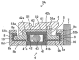
도 9에 도시하는 바와 같이, 라인 롤러(3A)는, 베어링 부재(4)와, 보지 부재(칼라 부재)(5)와, 안내 부재(6)를 구비한다. 나아가 라인 롤러(3A)는, 규제 부재(7), 제1 외부 그리스 보지부 형성 부재(8), 제2 외부 그리스 보지부 형성 부재(9)를 구비한다.As shown in Fig. 9, the
도 10에 도시하는 바와 같이, 제1 보지 부재(51)는, 제1 실부(51b)를 가지고 있다. 제1 실부(51b)는, 제1 어깨부(51a)의 하단부(下端部)로부터, 외륜(42)의 축 방향 좌방으로 연재하는 환상의 돌출부(환상 볼록부)이다. 마찬가지로, 제2 보지 부재(52)는 제2 실부(52b)를 가지고 있다. 제2 실부(52b)는, 제2 어깨부(52a)의 하단부로부터, 외륜(42)의 축 방향 우방으로 연재하는 환상의 돌출부(환상 볼록부)이다. 즉, 제1 실부(51b)와 제2 실부(52b)는, 베어링 부재(4)의 양측에서 반대 방향으로 대칭적으로 연재한다.As shown in Fig. 10, the first holding
전술과 같이, 베어링 부재(4)의 주위에는, 베어링 부재(4)로부터 안내 부재(6)(의 외주부, 라인 롤러(3A)의 외부 공간)까지 통하는 공간이 있다. 이 공간을 지나 해수 등이 베어링 부재(4)에까지 도달하면, 베어링 부재(4)의 기능이 저하하는 원인이 된다. 그 때문에, 해수 등이 베어링 부재(4)에까지 도달하지 않도록, 이 공간을 협애한 통로(래버린스)로 하고, 그 통로 공간에 발수성 그리스(10)를 보지한, 외부 그리스 보지부가 베어링 부재(4)의 양측의 2개소에 형성되어 있다. 2개소의 외부 그리스 보지부는, 제1 외부 그리스 보지부 형성 부재(8)와 제1 보지 부재(51)의 제1 실부(51b), 및 제2 외부 그리스 보지부 형성 부재(9)와 제2 보지 부재(52)의 제2 실부(52b)에 의하여 각각 구성되어 있다.As described above, there is a space around the bearing
제1 외부 그리스 보지부 형성 부재(8)는, 둘레 방향으로 형성된 통부(筒部)(환상 볼록부)(8b)와, 통부(8b)로부터 경방향으로 간격을 두고 둘레 방향으로 형성된 통부(환상 볼록부)(8c)와, 통부(8b)와 통부(8c)를 경방향으로 접속하는 평판부(8d)로 구성되어 있다. 통부(8c)는 평판부(8d)로부터 안내 부재(6)의 방향으로 연출하고 있지만, 안내 부재(6)와는 당접하지 않도록 구성되어 있다. 제1 외부 그리스 보지부 형성 부재(8)는, 바람직하게는 합성 수지제이다. 제1 외부 그리스 보지부 형성 부재(8)는, 제1 실부(51b)와 함께, 외부 그리스 보지부를 구성하고 있다.The first outer grease
구체적으로는, 제1 외부 그리스 보지부 형성 부재(8)는, 통부(8b)와 통부(8c)와의 사이에 환상의 함요부(환상 오목부)(8a)를 가지고 있다. 함요부(8a)는, 제1 보지 부재(51)의 제1 실부(51b)와 상보적인 형상을 가지고 있다. 제1 실부(51b)는, 함요부(8a)에 대향하고 있지만, 평판부(8d)에는 당접하지 않는다. 즉, 제1 실부(51b)는 환상 오목부(8a)에, 단면(斷面)이 コ자 형상의 래버린스 공간(간극(間隙))을 가지는 것과 같은 치수 구성으로 대향하고 있다. 이 공간(8a)에 발수성 그리스(10)가 보지되어 있다.Specifically, the first outer grease
발수성 그리스(10)는, 협애한 공간(8a)에 보지되어 있고, 또한 높은 조도(稠度)를 가지고 있기 때문에, 환상 오목부(8a)의 안내 부재(6) 측의 단부로부터 흘러나올 일은 없다.The
또한, 발수성 그리스(10)는, 베어링 부재(4)의 외면(外面)에도 도포되어 있다. 발수성 그리스(10)는, 접촉하는 해수 등을 흡수하지 않고 발수하기 위하여, 베어링 부재(4)의 외면에 발수성을 부여하고 있다. 또한, 발수성 그리스(10)는 라인 롤러(3A)의 외부로부터 베어링 부재(4)까지의 통로 공간에 보지되어 있기 때문에, 라인 롤러(3A)의 외부로부터 침입하려고 하는 해수 등이 베어링 부재(4)의 외면까지 도달하는 것을 효과적으로 억제할 수 있다.The
통부(8b)는, 그 베어링 부재(4) 측의 단부가 베어링 부재(4)의 내륜(41)의 제1 단부(41a)와 당접하고 있다. 즉, 제1 외부 그리스 보지부 형성 부재(8)는, 베어링 부재(4)의 위치를 도 10의 좌방으로부터 규제하는 규제 부재로서의 역할도 가지고 있다.The end of the
합성 수지제의 제2 외부 그리스 보지부 형성 부재(9)는, 베어링 부재(4)를 사이에 두고 제1 외부 그리스 보지부 형성 부재(8)의 반대 측에 배치되어 있다. 제2 외부 그리스 보지부 형성 부재(9)는, 축(O)에 직교하는 면에 대하여 제1 외부 그리스 보지부 형성 부재(8)와 대칭으로 형성되어 있다.The synthetic resin second external grease retaining
제2 외부 그리스 보지부 형성 부재(9)의 통부(9b)의 단부는 베어링 부재(4)의 내륜(41)의 제2 단부(41b)와 당접하고 있다. 또한, 제2 외부 그리스 보지부 형성 부재(9)가 베어링 부재(4)와 당접하는 측의 반대 측은, 규제 부재(7)가 당접하여 배치되어 있다.The end of the
제1 외부 그리스 보지부 형성 부재(8)와 마찬가지로, 제2 외부 그리스 보지부 형성 부재(9)는, 통부(환상 볼록부)(9b)와 통부(환상 볼록부)(9c)에 의하여 환상의 함요부(환상 오목부)(9a)를 형성하고 있다. 함요부(9a)는, 제2 보지 부재(52)의 제2 실부(52b)와 상보적인 형상을 가지고 있다. 제2 실부(52b)는, 환상 오목부(9a)에 대하여 단면이 コ자 형상의 래버린스 공간(간극)을 형성하도록 대향되어 있다. 이 공간(9a)에는 발수성 그리스(10)가 보지되어 있다. 이상과 같이, 제2 외부 그리스 보지부 형성 부재(9)는, 제2 실부(52b)와 함께, 발수성 그리스(10)를 보지하는 외부 그리스 보지부를 구성하고 있다.The second outer grease retaining
발수성 그리스(10)는, 협애한 공간(9a)에 보지되어 있고, 높은 조도를 가지도록 제조되어 있기 때문에, 환상 오목부(9a)의 안내 부재(6) 측의 단부로부터 흘러나올 일은 없다.The
또한, 발수성 그리스(10)는, 베어링 부재(4)의 외면에도 도포되어 있고, 베어링 부재(4)의 외면에 발수성을 부여한다.The
발수성 그리스(10)는, 해수나 하천수에 닿아도 그것을 발수하여 흡수하지 않는다. 그 때문에, 협애한 통로 공간(8a, 9a)에 해수 등이 침입하여도, 발수성 그리스(10)에 막혀 그것보다 안으로는 해수 등은 침입할 수 없다.The water-repellent grease (10) does not absorb water and water even if it touches seawater or river water. Therefore, even if seawater or the like intrudes into the
이상의 구성을 가지는 라인 롤러(3A)는, 베어링 부재(4)의 주위에, 제1 외부 그리스 보지부 형성 부재(8)와 제1 실부(51b)로 구성되는 외부 그리스 보지부가 구성되고, 그것에 발수성 그리스(10)가 보지되어 있다. 또한, 제2 외부 그리스 보지부 형성 부재(9)와 제2 실부(52b)로 구성되는 외부 그리스 보지부가 구성되고, 그것에 발수성 그리스(10)가 보지되어 있다. 이것들의 외부 그리스 보지부는 コ자 형상으로 굴곡한 협애한 공간을 형성하고 있기 때문에, 발수성 그리스(10)를 보지하는 효과가 높다. 그 때문에, 라인 롤러(3A)의 외부로부터 해수 등이 베어링 부재(4)의 내부에까지 침입하는 것을 한층 더 효과적으로 억제하고, 베어링 부재(4)의 결함을 억제할 수 있다.The
(실시예 3)(Example 3)
이상, 실시예 1 및 2로서, 1개의 베어링 부재(4)의 내부 또는 내부와 외부에 각각 그리스 보지부를 설치한 라인 롤러(3 및 3A)를 설명하였다. 그러나 베어링 부재는 1개로 한정하지 않고 2개 이상의 베어링 부재를 가지는 것이어도 무방하다. 이하에, 2개의 베어링 부재를 가지는 본 발명의 실시예 3에 관련되는 라인 롤러(3B)에 관하여, 도 11을 이용하여 설명한다. 덧붙여, 실시예 1과 공통하는 부재에 관하여는 공통의 부호를 붙이고, 실시예 1의 라인 롤러(3)와 다른 부분을 중심으로 설명한다.As the first and second embodiments, the
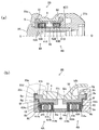
라인 롤러(3B)는, 도 11(a)에 도시하는 바와 같이 지지축(24)의 외주에 2개의 볼 베어링(베어링 부재)(4A, 4B)과, 규제 부재(45)와, 제1 외부 그리스 보지부 형성 부재(8)와, 제2 외부 그리스 보지부 형성 부재(9)와, 제1 보지 부재(칼라 부재)(51)와, 제2 보지 부재(칼라 부재)(52)와, 안내 부재(6)를 구비한다. 베어링 부재(4A, 4B)는, 모두 실시예 1의 베어링 부재(4)와 같은 구조이다. 덧붙여, 도 11(a)에서는 발수성 그리스는 도시하고 있지 않다.The
도 11(b)에 도시하는 바와 같이, 베어링 부재(4A)의 내륜(41A)의 제1 단부(41Aa)는, 제1 외부 그리스 보지부 형성 부재(8)의 통부(8b)에 당접하고 있다. 또한 내륜(41A)의 제2 단부(41Ab)는, 규제 부재(45)의 제1 단부(45a)에 당접하고 있다. 베어링 부재(4B)의 내륜(41B)의 제1 단부(41Ba)는, 제2 외부 그리스 보지부 형성 부재(9)의 통부(9b)와 당접하고 있다. 또한 내륜(41B)의 제2 단부(41Bb)는, 규제 부재(45)의 제2 단부(45b)와 당접하고 있다. 즉, 베어링 부재(4A, 4B)는, 양측의 제1 외부 그리스 보지부 형성 부재(8) 및 제2 외부 그리스 보지부 형성 부재(9)와 중간의 규제 부재(45)에 의하여 그 위치가 규제되어 있다.The first end portion 41Aa of the
외륜(42A)의 외주는 제1 보지 부재(51)의 내주와 계합하고 있다. 제1 보지 부재(51)의 축 방향 내측(內側)의 단부(51c)는 직경 내측 방향으로 연출하고, 외륜(42A)의 제2 단부(42Ab)와 당접하고 있다. 제1 보지 부재(51)의 단부(51c)와 반대 측의 단부는, 외륜(42A)의 축 방향 외측 단면의 위치로부터 경방향으로 연출하고, 나아가 축 외측 방향으로 굴곡하여 환상 볼록부(51b)가 형성되어 있다.The outer periphery of the
외륜(42B)의 외주는 제2 보지 부재(52)의 내주와 계합하고 있다. 제2 보지 부재(52)의 축 방향 내측의 단부(52c)는 직경 내측 방향으로 연출하고, 외륜(42B)의 제2 단부(42Bb)와 당접하고 있다. 제2 보지 부재(52)의 단부(52c)와 반대 측의 단부는, 외륜(42B)의 축 방향 외측 단면의 위치로부터 경방향으로 연출하고, 나아가 축 외측 방향으로 굴곡하여 환상 볼록부(52b)가 형성되어 있다.The outer periphery of the
안내 부재(6)의 내주는, 제1 보지 부재(51)와 제2 보지 부재(52)의 외주에 계합하고 있다. 그 때문에, 안내 부재(6)는, 제1 보지 부재(51)와 제2 보지 부재(52)를 통하여 베어링 부재(4A, 4B)의 외륜(42A, 42B)과 함께 회전한다.The inner periphery of the
제1 외부 그리스 보지부 형성 부재(8)는, 지지축(24)에 접하는 통부(환상 볼록부)(8b), 통부(8b)로부터 경방향으로 연출하는 평판부(8d)로 구성되어 있다. 평판부(8d)의 축 방향의 폭은 통부(8b)보다도 작다. 그 때문에 평판부(8d)와 제1 보지 부재(51) 및 베어링 부재(4A)와의 사이에 공간(외부 그리스 보지부)(8f)이 형성되어 있다.The first outer grease
제1 외부 그리스 보지부 형성 부재(8)는, 축 방향 외측의 단부가 베일(23)의 제1 단부(23a)의 내측에 설치한 오목부(23c)에 당접하고 있다. 평판부(8d)의 외주(8g)와 오목부(23c)의 벽부(23d)와의 사이에 공간(환상 오목부(8a))이 형성되어 있다. 이 환상 오목부(8a)에, 제1 보지 부재(51)의 환상 볼록부(51b)가 공간(환상 오목부(8a)와 환상 볼록부(51b)가 이루는 공간)(8a)을 형성하도록 대향되어 있다.The first outer grease retaining
공간(8f)과 공간(8a)에는 발수성 그리스(10)가 보지되어 있다. 공간(8f)에 보지된 발수성 그리스(10)는, 외륜(42A)의 외측면(42Ac)에 접하도록 보지되어 있고, 해수 등이 베어링 부재(4A)의 표면까지 도달하는 것을 억제한다. 덧붙여, 도 11(b)에서는 발수성 그리스(10)는 베어링 부재(4A)의 좌측면의 일부에 충전되어 있지 않는 부분이 있지만, 발수성 그리스(10)가 좌측면 전체에 충전되어 있어도 무방하다.The water-
제2 외부 그리스 보지부 형성 부재(9)는, 지지축(24)에 접하는 통부(환상 볼록부)(9b), 통부(9b)와 경방향으로 간격을 두고 형성된 통부(환상 볼록부)(9c)를 구비한다. 통부(9b)와 통부(9c)의 사이는, 평판부(9e)로 결합되어 있다. 평판부(9e)는, 통부(9c)의 측에 함요부(환상 오목부)(9a)가 형성되어 있다. 환상 오목부(9a)에는, 제2 보지 부재(52)의 환상 볼록부(52b)가 공간(환상 오목부(9a)와 환상 볼록부(52b)가 이루는 공간)(9a)을 형성하도록 대향 배치되어 있다. 또한, 환상 오목부(9a)를 제외하는 평판부(9e)의 축 방향의 면과 베어링 부재(4B)와의 사이는 공간(9f)(외부 그리스 보지부)이 형성되어 있다.The second external grease
공간(9f)과 공간(9a)에는 발수성 그리스(10)가 보지되어 있다. 공간(9f)에 보지된 발수성 그리스(10)는, 외륜(42B)의 외측면(42Bc)에 접하도록 보지되어 있고, 해수 등이 베어링 부재(4B)의 표면까지 도달하는 것을 억제한다. 덧붙여, 도 11(b)에서는 발수성 그리스(10)는 베어링 부재(4B)의 우측면의 일부에 충전되어 있지 않는 부분이 있지만, 발수성 그리스(10)가 우측면 전체에 충전되어 있어도 무방하다.The water-
통부(9c)는 제2 외부 그리스 보지부 형성 부재(9)의 가장 외주 측에 배설되어 있고, 그 내주에 그리스 받이부(9g)가 형성되어 있다. 발수성 그리스(10)는 통상(通常)의 사용 조건 하에서 흘러나오는 일이 없도록 충분한 조도를 가지도록 조제되어 있다. 그러나 라인 롤러(3B)에는 도 11(b)의 상방향으로 강한 원심력이 작용하기 때문에, 일부가 흘러나올 가능성이 있다. 그리스 받이부(9g)는, 만일 발수성 그리스(10)가 흘러나온 경우에 그것을 받아들이기 위한 공간이다. 덧붙여, 이와 같은 그리스 받이부(9g)를, 제1 외부 그리스 보지부 형성 부재(8)의 측에도 설치하여도 무방하다.The
이상의 구성을 가지는 라인 롤러(3B)는, 베어링 부재(4A, 4B)의 외부에 굴곡한 협애한 공간(래버린스)을 형성한 외부 그리스 보지부를 가지고 있기 때문에, 발수성 그리스(10)를 보지하는 효과가 높다. 그 때문에, 해수 등이 라인 롤러(3B)의 외부로부터 베어링 부재(4A, 4B)의 내부에까지 침입하는 것을 한층 더 억제할 수 있고, 해수 등을 원인으로 하는 베어링 부재(4A, 4B)의 결함을 억제할 수 있다.The
덧붙여, 실시예 3에서는, 2개의 베어링 부재(4A, 4B)의 내부 및 외부의 양방(兩方)에 그리스 보지부를 설치하였지만, 2개의 베어링 부재(4A, 4B)의 내부에만 그리스 보지부를 설치하는 구성이어도 무방하다.In the third embodiment, the grease holding portions are provided on both the inside and the outside of the two bearing
이상, 실시예 2 및 3으로서 베어링 부재(4)의 내부의 그리스 보지부에 더하여, 외부 그리스 보지부를 가지는 실시예에 관하여 설명하였다. 그러나 외부 그리스 보지부의 형상은 이것들로 한정되는 것이 아니고, 이하와 같이 여러 가지의 변경이 가능하다.As above,
(변형예 5)(Modified Example 5)
실시예 2에서는, 제1 외부 그리스 보지부 형성 부재(8) 및 제2 외부 그리스 보지부 형성 부재(9)는 1개의 환상 오목 부재로서 구성하였다. 그러나 제1 외부 그리스 보지부 형성 부재(8) 및 제2 외부 그리스 보지부 형성 부재(9)의 구성은 이것으로 한정되지 않고, 복수의 부재로 구성하여도 무방하다.In the second embodiment, the first external grease holding
변형예 5에 관련되는 라인 롤러(3C)는, 도 12에 도시하는 바와 같이, 제1 외부 그리스 보지부 형성 부재(8)의 환상 오목부(8a)는, 통부(8c)와 경방향으로 연재하는 평판부(8d)를 가지는 부재(8A)에, 지지축(24)의 주위에 형성된 통상 부재(8B)를 당접시켜 형성되어 있다.12, the annular
통부(8c)와 통상 부재(8B)와의 간격이나, 통상 부재(8B)의 축 방향의 길이는, 환상 오목부(8a)에 제1 실부(51b)를 대향시켰을 때에, 양자의 사이에 공간(환상 오목부(8a)와 제1 실부(51b)가 이루는 공간)(8a)이 형성되는 치수로 구성되어 있다. 이 공간(8a)에 발수성 그리스(10)가 보지되어 있다. 덧붙여, 통상 부재(8B)는 베어링 부재(4)의 위치를 규제하는 규제 부재를 겸하고 있다. 또한 제2 외부 그리스 보지부 형성 부재(9)에도 마찬가지의 구성을 이용하고 있다. 즉, 부재(9A)와 통상 부재(9B)를 조합하여 공간(환상 오목부(9a))을 구성하고, 제2 실부(52b)와 대향시키고, 그 공간(환상 오목부(9a)와 제2 실부(52b)가 이루는 공간)(9a)에 발수성 그리스(10)가 보지되어 있다. 이와 같은 구성에서도 실시예 2와 마찬가지의 효과를 얻을 수 있다.The interval between the
변형예 5에서는, 실시예 2에 비하여 제1 외부 그리스 보지부 형성 부재(8) 및 제2 그리스 보지부 형성 부재(9)의 제조가 용이하게 되고, 염가로 외부 그리스 보지부를 형성할 수 있다. 예를 들어, 부재(8A)는 프레스 부재로 하고, 통상 부재(8B)는 절삭 부재로 하여 제조할 수 있고, 일체 성형이나 깍아냄으로 성형하는 제1 외부 그리스 보지부 형성 부재(8)보다도 염가로 제조할 수 있다.In the fifth modified example, the first external grease retaining
(변형예 6)(Modified Example 6)
변형예 6에 관련되는 라인 롤러(3D)는, 제1 외부 그리스 보지부 형성 부재(8) 및 제2 외부 그리스 보지부 형성 부재(9)의 구조로서 베일(23)의 제1 단부(23a)나 제1 베일 지지 부재(21)의 제2 단부(21b)의 일부를 조합하고 있다. 구체적으로는, 도 13에 도시하는 바와 같이, 베일(23)의 제1 단부(23a)의 내측에 오목부(23c)가 형성되어 있다. 오목부(23c)의 단부에 접하도록, 통상 부재(8B)가 배치되어 있다. 오목부(23c)와 통상 부재(8B)의 외표면과의 사이에 환상 오목부(8a)가 형성되어 있다. 이 환상 오목부(8a)와 제1 보지 부재(51)의 제1 실부(51b)를 대향시키면, 양자의 사이에 공간(간극)이 생기는 치수로 제1 단부(23a)와 통상 부재(8B)가 구성되어 있다. 그리고 이 공간에 발수성 그리스(10)가 보지되어 있다.The line roller 3D according to Modification Example 6 has the
또한 제1 베일 지지 부재(21)의 제2 단부(21b)의 내측에, 돌기(21e)와 나아가 그 내측에 오목부(21d)가 형성되어 있다. 규제 부재(7)가 오목부(21d)의 측면에 당접하여 배치되고, 지지축(24)에 접하여 형성된 통상 부재(9B)가 규제 부재(7)와 베어링 부재(4)의 내륜(41)에 끼여 배치되어 있다. 돌기와 규제 부재(7)와 통상 부재(9B)에 둘러싸인 영역이 환상 오목부(9a)로 된다. 환상 오목부(9a)와 제2 실부(52b)를 대향시켜 형성되는 공간(간극)에 발수성 그리스(10)가 보지되어 있다. 이와 같은 구성에서도 실시예 2와 마찬가지의 효과를 얻을 수 있다.A recess 21d is formed inside the projection 21e and further inside the
변형예 6에서는, 베일(23)의 제1 단부(23a)나 제1 베일 지지 부재(21)의 제2 단부(21b)의 구조를 일부 변경하는 것만으로, 변형예 5에 비하여 부재(8A)나 부재(9A)를 생략할 수 있고, 제조 코스트를 한층 더 삭감할 수 있다.In
(변형예 7) (Modification 7)
실시예 2에서는, 환상 오목부를 형성하여 외부 그리스 보지부를 구성하였다. 그러나 외부 그리스 보지부의 구조는 이것으로 한정되지 않는다. 예를 들어, 축 방향으로, 서로 대향하는 방향으로 1 이상의 환상 볼록부(재(材))를 공간(간극)을 가지고 인접하여 배치하고, 그 공간에 발수성 그리스(10)를 보지하여도 무방하다(도시하지 않음).In Example 2, an external grease holding portion was formed by forming an annular concave portion. However, the structure of the external grease holding portion is not limited to this. For example, one or more annular convex portions (materials) may be disposed adjacent to each other with a space (gap) in the direction opposite to each other in the axial direction, and the water-
실시예 2에서는, コ자 형상으로 굴곡한 공간(간극)을 형성하여 그 사이에 발수성 그리스(10)를 보지하였지만, 반드시 コ자 형상으로 굴곡한 공간이 아니어도 무방하다. 상기와 같이, 2개의 환상 볼록부의 직선상(直線狀)의 공간(간극)에 발수성 그리스(10)를 보지하는 구성이어도 무방하다. 또한, 공간이 크랭크 형상으로 굴곡하도록 볼록 부재, 오목 부재 등을 조합하여도 무방하다(도시하지 않음). 이 경우도 베일 부재나 베일 지지 부재를 이용하여도 무방하다.In the second embodiment, the space (gap) bent in a U-shape is formed and the water-
또한 실시예 2나 3에서는, 베어링 부재(4)의 회전축 방향으로 연출하는 환상 볼록부나 축 방향으로 함요하는 환상 오목부를 형성하여 외부 그리스 보지부가 구성되어 있다. 그러나 이것으로 한정하지 않고, 축 방향으로 직교하는 방향(경방향)으로 환상 볼록부나 환상 오목부를 형성하여 조합하여도 무방하다(도시하지 않음).In the second and third embodiments, the outer grease holding portion is formed by forming the annular convex portion extending in the rotational axis direction of the bearing
(변형예 8)(Modification 8)
실시예 2, 3에서는, 환상 오목부와 환상 볼록부를 형성하여 외부 그리스 보지부를 구성하였다. 그러나 외부 그리스 보지부는 이것으로 한정되지 않는다.In Examples 2 and 3, an annular concave portion and an annular convex portion were formed to constitute an external grease holding portion. However, the outer grease holding portion is not limited to this.
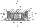
도 14에 도시하는 변형예 8에 관련되는 라인 롤러(3E)는, 베어링 부재(4)의 양측에 탄성 부재로 이루어지는 립 실(80, 90)을 형성하여 발수성 그리스(10)를 보지하고 있다. 립 실(80, 90)은, 합성 고무 또는 천연 고무 등에 의하여 형성할 수 있고, 구체적으로는 부타디엔과 아크릴로니트릴과의 공중합체인 니트릴 부타디엔 고무 등에 의하여 형성할 수 있다.The
라인 롤러(3E)는, 안내 부재(6)와 베어링 부재(4)와의 사이에 보지 부재(5)를 설치하고 있지 않다. 립 실(80)은, 안내 부재(6)의 일방의 단부에 형성된 단차부(段差部)(6a)에 고정된 고정부(81)와, 고정부(81)로부터 선단부를 향하여 두께가 얇아지는 립부(82)로 이루어진다. 립 실(90)은, 안내 부재(6)의 타방의 단부에 형성된 단차부(6b)에 고정된 고정부(91)와, 고정부(91)로부터 선단부를 향하여 두께가 얇아지는 립부(92)로 이루어진다.The
립부(82, 92)의 선단은, 각각 베어링 부재(4)의 위치를 규제하는 규제 부재(7A, 7B)에 접하고 있다. 발수성 그리스(10)는, 립 실(80)과 베어링 부재(4)와의 사이, 및 립 실(90)과 베어링 부재(4)와의 사이에 보지되어 있다. 이 구조에 의하여, 해수 등이 베어링 부재(4)에 도달하는 것을 억제할 수 있다.The tip ends of the
덧붙여, 규제 부재(7A, 7B)를 설치하지 않고 , 립부(82, 92)가 지지 부재(24)에 직접 접하도록 하여도 무방하다. 또한 립 실(80, 90)은, 규제 부재(7A, 7B)(또는 지지 부재(24))에 고정부(81, 91)를 고정하여, 안내 부재(6)의 방향으로 립부(82, 92)를 향하여 구성하여도 무방하다. 또한, 보지 부재(5)를 설치하여 보지 부재(5)에 립 실(80, 90)을 고정하여도 무방하다(모두 도시하지 않음).It is to be noted that the
(변형예 9)(Modified Example 9)
상기의 실시예 2, 3에 있어서, 그리스의 보지 성능을 보다 높이기 위하여, 외부 그리스 보지 공간을 설치하여도 무방하다. 실시예 3에 관련되는 라인 롤러(3B)에 외부 그리스 보지부를 설치한 변형예 9를 도 15를 참조하여 설명한다.In the above-described
도 15에 도시하는 바와 같이, 제1 외부 그리스 보지부 형성 부재(8)는, 평판부(8d)의, 베어링 부재(4A)의 외륜(42A)의 외측면에 면하는 위치에 함요부인 공간(외부 그리스 보지부)(8e)을 설치하고 있다. 그리고 외부 그리스 보지부(8e), 공간(8f), 공간(8a)에 발수성 그리스(10)가 보지되어 있다. 외부 그리스 보지부(8e)를 설치한 것에 의하여, 도면의 상방향으로 작용하는 원심력에 대하여 그리스의 보지력이 한층 더 향상한다.15, the first outer grease retaining
또한, 제2 외부 그리스 보지부 형성 부재(9)의 측에 있어서도, 단차(9d)의, 베어링 부재(4B)의 외륜(42B)의 외측면에 면하는 위치에 함요부인 공간(외부 그리스 보지부)(9h)을 설치하고 있다. 그리고 외부 그리스 보지부(9h), 공간(외부 그리스 보지부)(9j), 공간(9a)에 발수성 그리스(10)가 보지되어 있다. 외부 그리스 보지부(9h)를 설치한 것에 의하여, 도면의 상방향으로 작용하는 원심력에 대하여 그리스의 보지력이 한층 더 향상한다.In the side of the second outer grease retaining
(변형예 10)(Modified Example 10)
실시예 1 - 3 및 변형예 1 - 10에 나타낸 베어링 부재(4, 4A, 4B)에 있어서, 베어링 부재(4, 4A, 4B)의 내부 전체에 발수성 그리스를 충전하는 구성이어도 무방하다(도시하지 않음). 이 구성에서는, 발수성 그리스의 유출을 한층 더 억제할 수 있고, 베어링 부재(4A, 4B)의 발수성을 한층 더 높일 수 있다.4A and 4B shown in Embodiments 1 to 3 and Modifications 1 to 10 may be constructed such that the entire interior of the bearing
또한, 베어링 부재(4, 4A, 4B)의 내부에 발수성 그리스가 아니고, 윤활용의 그리스를 충전하여도 무방하다(도시하지 않음). 베어링 부재(4, 4A, 4B)의 그리스 보지부에는 발수성 그리스(10)가 보지되어 있지만, 발수성 그리스(10)는 해수 등이 침입하는 것을 방지하기 위하여 발수성을 중시한 그리스이다. 그래서 베어링 부재(4, 4A, 4B)의 내부에 윤활용의 그리스를 충전하는 것으로, 윤활성도 향상시킨 라인 롤러로 할 수 있다.The bearing
또한, 발수성 그리스(10)는, 베어링 부재(4, 4A, 4B)의 측면이나 외주면에 도포하여 보지하여도 무방하다. 또한 발수성 그리스(10)는, 베어링 부재(4, 4A, 4B)의 측면이나 외주면으로부터 외부 그리스 보지부의 내부까지의 일부에 충전하여도 무방하고, 전체에 걸쳐 충전하여도 무방하다.The
상기의 베어링 부재(4, 4A, 4B)는 볼 베어링으로 하였다. 그러나 이것으로 한정하지 않고, 베어링 부재(4)는 구름 베어링이면 된다. 예를 들어 전동체(43)는 원통(굴림대)상이어도 무방하다.The
상기의 실시예 1 - 3 및 변형예 1 - 10에 나타낸 베어링 부재(4, 4A, 4B)의 내부 및 외부의 그리스 보지부의 구조는, 임의로 조합하는 것이 가능하다.The structures of the inside and outside grease holding portions of the bearing
2: 낚싯줄 안내 기구
3, 3A, 3B, 3C, 3D, 3E: 라인 롤러
4, 4A, 4B: 베어링 부재(볼 베어링)
41, 41A, 41B: 내륜
42, 42A, 42B: 외륜
41a, 42a, 41Aa, 41Ba: 제1 단부
41b, 42b, 41Ab, 41Bb, 42Ab, 42Bb: 제2 단부
42Ac, 42Bc: 외측면
43, 43A, 43B: 전동체
46A, 46B: 제1 그리스 보지부 형성부
46a, 46b, 46c, 46d: 볼록부
47A, 47B: 제2 그리스 보지부 형성부
47a, 47b, 47c, 47d: 볼록부
48A, 48B: 제1 그리스 보지부 형성부
49A, 49B, 49C, 49D: 제2 그리스 보지부 형성부
5: 보지 부재(칼라 부재)
51: 제1 보지 부재(칼라 부재)
52: 제2 보지 부재(칼라 부재)
51a: 제1 어깨부
52a: 제2 어깨부
51b: 제1 실부(환상 볼록부)
52b: 제2 실부(환상 볼록부)
51c, 52c: 단부
53a, 53b, 54a, 54b: 볼록부
6: 안내 부재
61: 가이드면
62: 홈부
6a, 6b: 단차부
7, 7A, 7B: 규제 부재
8: 제1 외부 그리스 보지부 형성 부재
8A: 부재
8B: 통상 부재
8a: 공간(함요부, 환상 오목부)
8b, 8c: 통부(환상 볼록부)
8d: 평판부
8e: 공간(외부 그리스 보지부)
8f: 공간(외부 그리스 보지부)
8g: 외주
9: 제2 외부 그리스 보지부 형성 부재
9A: 부재
9B: 통상 부재
9a: 공간(함요부, 환상 오목부)
9b, 9c: 통부(환상 볼록부)
9d: 단차
9e: 평판부
9f: 공간(외부 그리스 보지부)
9g: 그리스 받이부
9h: 공간(외부 그리스 보지부)
9j: 공간(외부 그리스 보지부)
10: 발수성 그리스
21: 제1 베일 지지 부재
21a: 제1 단부
21b: 제2 단부
21c: 관통공
21d: 오목부
21e: 돌기
22: 제2 베일 지지 부재
22a: 제1 단부
22b: 제2 단부
23: 베일
23a: 제1 단부(커버부)
23b: 제2 단부
23c: 오목부
23d: 벽부
24: 지지축(지지 부재)
241: 통상부
241a: 축부
241b: 머리부
242: 볼트부
242a: 축부
242b: 머리부
44A, 44B, 45: 규제 부재
45a: 제1 단부
45b: 제2 단부
80, 90: 립 실
81, 91: 고정부
82, 92: 립부
100: 낚시용 스피닝 릴
110: 릴 본체
111: 케이스부
112: 덮개부
113: 장착부
120: 로터
121: 로터 본체부
122: 제1 로터 암
123: 제2 로터 암
130: 스풀
140: 핸들
141: 핸들축
150: 구동 기구
151: 구동축
152: 구동 기어
160: 오실레이팅 기구
170: 피니언 기어
171: 기어부
180: 스풀축2: fishing line guide mechanism
3, 3A, 3B, 3C, 3D, 3E: Line roller
4, 4A, 4B: Bearing member (ball bearing)
41, 41A, 41B: inner ring
42, 42A, 42B: outer ring
41a, 42a, 41Aa, 41Ba: a first end
41b, 42b, 41Ab, 41Bb, 42Ab, 42Bb:
42Ac, 42Bc: outer surface
43, 43A, 43B:
46A, 46B: a first grease holding part forming part
46a, 46b, 46c, and 46d:
47A and 47B: the second grease holding part forming part
47a, 47b, 47c, and 47d:
48A and 48B: the first grease holding part forming part
49A, 49B, 49C, 49D: the second grease holding portion forming portion
5: holding member (collar member)
51: first holding member (collar member)
52: second holding member (collar member)
51a: first shoulder part
52a: second shoulder portion
51b: first seal portion (annular convex portion)
52b: second seal portion (annular convex portion)
51c and 52c:
53a, 53b, 54a, 54b:
6: guide member
61: Guide face
62: Groove
6a and 6b:
7, 7A, 7B: Regulatory member
8: First outer grease retaining member forming member
8A: absence
8B: Normal member
8a: space (concave, annular concave)
8b, 8c: cylinder portion (annular convex portion)
8d:
8e: space (outer grease holding part)
8f: space (outer grease holding part)
8g: outsourcing
9: Second outer grease retaining member forming member
9A: absence
9B: normal member
9a: space (concave portion, annular concave portion)
9b, 9c: cylinder portion (annular convex portion)
9d: step
9e:
9f: space (outer grease holding part)
9g: grease receiving part
9h: space (outer grease holding part)
9j: Space (outer grease holding part)
10: Water repellent grease
21: first bail support member
21a: First end
21b: second end
21c: Through-hole
21d:
21e: projection
22: second bail support member
22a: first end
22b: second end
23: Veil
23a: a first end portion (cover portion)
23b: second end
23c:
23d: wall portion
24: Support shaft (supporting member)
241:
241a:
241b:
242:
242a:
242b:
44A, 44B, 45: regulating member
45a: first end
45b: second end
80, 90: Lip thread
81, 91:
82, 92: Lip part
100: Spinning reel for fishing
110: Reel unit
111: Case part
112:
113:
120: Rotor
121:
122: first rotor arm
123: 2nd rotor arm
130: spool
140: Handle
141: handle shaft
150: drive mechanism
151:
152: drive gear
160: Oscillating mechanism
170: Pinion gear
171:
180: Spool shaft
Claims (14)
낚싯줄을 안내하는 가이드면을 외주(外周)에 가지는 원통상(圓筒狀)의 안내 부재와,
상기 안내 부재의 내주면(內周面)을 회전 가능하게 지지하는 베어링 부재와,
상기 베어링 부재를 지지하는 지지 부재를 구비하고,
상기 베어링 부재는, 상기 지지 부재에 지지된 내륜(內輪)과, 상기 안내 부재와 일체로 되어 회전하는 외륜(外輪)과, 상기 내륜과 상기 외륜과의 사이에 배치된 전동체와, 상기 내륜과 상기 외륜과의 사이에서 발수성(撥水性) 그리스(grease)를 보지(保持)하는 그리스 보지부를 가지는,
라인 롤러.A line roller for guiding a fishing line by a spool of a fishing spinning reel,
A cylindrical guide member having a guide surface for guiding a fishing line on an outer circumference thereof,
A bearing member rotatably supporting an inner circumferential surface of the guide member,
And a support member for supporting the bearing member,
Wherein the bearing member includes an inner ring supported by the support member, an outer ring rotated integrally with the guide member, a rolling member disposed between the inner ring and the outer ring, And a grease holding portion for holding a water-repellent grease between the inner ring and the outer ring,
Line roller.
상기 그리스 보지부는,
상기 내륜으로부터 직경 외측(外側) 방향으로 돌출하는 제1 그리스 보지부 형성부와,
상기 외륜으로부터 직경 내측(內側) 방향으로 돌출하고, 상기 제1 그리스 보지부 형성부의 측면과 대향하는 측면을 가지는 제2 그리스 보지부 형성부를 가지고,
상기 제1 그리스 보지부 형성부의 측면과 상기 제2 그리스 보지부 형성부의 측면과의 사이에 상기 발수성 그리스가 보지되어 있는,
라인 롤러.The method according to claim 1,
The grease-
A first grease holding portion forming portion that protrudes in a radially outward (outer) direction from the inner ring,
And a second grease holding portion forming portion protruding inwardly in a radial direction from the outer ring and having a side opposite to a side surface of the first grease holding portion forming portion,
Wherein the water repellent grease is held between a side surface of the first grease retaining portion forming portion and a side surface of the second grease holding portion forming portion,
Line roller.
상기 그리스 보지부는, 상기 제1 그리스 보지부 형성부의 측면과 상기 제2 그리스 보지부 형성부의 측면이 상보적으로 굴곡하여 대향하는, 라인 롤러.3. The method of claim 2,
Wherein the side surface of the first grease holding portion forming portion and the side surface of the second grease holding portion forming portion complementarily bend and oppose each other.
상기 그리스 보지부는, 상기 제2 그리스 보지부 형성부가 오목부를 가지고, 상기 제1 그리스 보지부 형성부가 상기 오목부에 간극을 가지고 삽입되고, 상기 간극에 상기 발수성 그리스가 보지되어 있는, 라인 롤러.The method according to claim 2 or 3,
Wherein the grease holding portion has a concave portion in the second grease holding portion forming portion, the first grease holding portion forming portion is inserted with a gap in the concave portion, and the water repellent grease is held in the gap.
상기 안내 부재와 상기 외륜과의 사이에, 상기 안내 부재와 상기 외륜을 결합하는 보지 부재를 더 구비하고, 상기 보지 부재의 일부가 상기 제2 그리스 보지부 형성부를 겸하는, 라인 롤러.5. The method according to any one of claims 2 to 4,
Further comprising a holding member for coupling the guide member and the outer ring between the guide member and the outer ring, wherein a part of the holding member also serves as the second grease holding portion forming portion.
상기 베어링 부재로부터 상기 안내 부재까지 통하는 공간을 구성하는 것과 함께 상기 공간에 발수성 그리스를 보지한 외부 그리스 보지부를 더 구비하는, 라인 롤러.6. The method according to any one of claims 1 to 5,
Further comprising an external grease retaining portion which constitutes a space communicating from the bearing member to the guide member and in which the water repellent grease is held in the space.
상기 외부 그리스 보지부는, 상기 안내 부재와 상기 지지 부재와의 사이에 배치된 탄성 부재로 이루어지는 실(seal) 부재를 포함하는, 라인 롤러.The method according to claim 6,
Wherein the outer grease retaining portion includes a seal member formed of an elastic member disposed between the guide member and the support member.
상기 실 부재는,
상기 안내 부재 및 상기 지지 부재 중 어느 일방(一方)의 부재에 고정되는 고정부와,
상기 고정부로부터 타방(他方)의 부재를 향하여 연재(延在)하고, 선단부(先端部)의 두께가 상기 고정부의 두께보다도 얇게 형성된 립부를 구비하는,
라인 롤러.8. The method of claim 7,
Wherein,
A fixing part fixed to a member of one (one) of the guide member and the support member,
And a lip portion extending from the fixing portion toward the other member and having a thickness smaller than a thickness of the fixing portion,
Line roller.
상기 외부 그리스 보지부는,
상기 베어링 부재의 회전축 방향 또는 경(徑)방향으로 돌출한 환상(環狀) 볼록부를 가지는 제1 환상 볼록 부재와,
상기 환상 볼록부에 대향하는 방향으로 인접하여 돌출한 환상 볼록부를 가지는 제2 환상 볼록 부재를 포함하는,
라인 롤러.The method according to claim 6,
The external grease holding part
A first annular convex member having an annular convex portion protruding in a direction of a rotation axis or a radius of the bearing member;
And a second annular convex member having an annular convex portion protruding adjacent to the annular convex portion in a direction opposite to the annular convex portion,
Line roller.
상기 외부 그리스 보지부는,
상기 베어링 부재의 회전축 방향 또는 경방향으로 돌출한 환상 볼록부를 가지는 환상 볼록 부재와,
상기 환상 볼록부와 대향하는, 상기 환상 볼록부와 상보적으로 함요(陷凹)한 환상 오목부를 가지는 환상 오목 부재를 포함하는,
라인 롤러.The method according to claim 6,
The external grease holding part
An annular convex member having an annular convex portion protruding in a direction of a rotational axis of the bearing member or in a radial direction;
And an annular concave member facing the annular convex portion and having an annular concave portion complementarily recessed with the annular convex portion,
Line roller.
상기 발수성 그리스는, 상기 베어링 부재의 회전 지지축 방향의 일방의 외단면(外端面)과 상기 안내 부재까지 통하는 상기 공간의 적어도 일부에 보지되어 있는, 라인 롤러.11. The method according to any one of claims 6 to 10,
Wherein the water repellent grease is held in at least one part of an outer end face of the bearing member in the direction of the rotation support axis and in the space leading to the guide member.
상기 발수성 그리스가, 상기 베어링 부재의 내부에 충전(充塡)되어 있는, 라인 롤러.12. The method according to any one of claims 1 to 11,
Wherein the water repellent grease is filled in the bearing member.
상기 발수성 그리스와 다른 윤활용 그리스가, 상기 베어링 부재의 내부에 충전되어 있는, 라인 롤러.12. The method according to any one of claims 1 to 11,
And the lubricating grease different from the water repellent grease is filled in the bearing member.
상기 베어링 부재로부터 상기 안내 부재까지 통하는 공간을 구성하는 것과 함께 상기 공간에 발수성 그리스를 보지한 외부 그리스 보지부를 구비하고, 상기 보지 부재의 일부가 상기 외부 그리스 보지부의 일부를 구성하는, 라인 롤러.6. The method of claim 5,
And an outer grease retaining portion that constitutes a space communicating from the bearing member to the guide member and in which the water repellent grease is held in the space, and a part of the retaining member constitutes a part of the outer grease retaining portion.
Applications Claiming Priority (2)
| Application Number | Priority Date | Filing Date | Title |
|---|---|---|---|
| JPJP-P-2015-253140 | 2015-12-25 | ||
| JP2015253140A JP6700778B2 (en) | 2015-12-25 | 2015-12-25 | Line roller |
Publications (2)
| Publication Number | Publication Date |
|---|---|
| KR20170077016A true KR20170077016A (en) | 2017-07-05 |
| KR102656378B1 KR102656378B1 (en) | 2024-04-12 |
Family
ID=57590338
Family Applications (1)
| Application Number | Title | Priority Date | Filing Date |
|---|---|---|---|
| KR1020160105936A KR102656378B1 (en) | 2015-12-25 | 2016-08-22 | Line roller |
Country Status (7)
| Country | Link |
|---|---|
| US (1) | US9961888B2 (en) |
| EP (1) | EP3183962B1 (en) |
| JP (1) | JP6700778B2 (en) |
| KR (1) | KR102656378B1 (en) |
| CN (1) | CN107018966B (en) |
| MY (1) | MY183285A (en) |
| TW (1) | TWI710314B (en) |
Families Citing this family (4)
| Publication number | Priority date | Publication date | Assignee | Title |
|---|---|---|---|---|
| KR102656377B1 (en) * | 2015-12-11 | 2024-04-12 | 가부시키가이샤 시마노 | Line roller and spinning reel using the line roller |
| JP6856355B2 (en) * | 2016-11-08 | 2021-04-07 | 株式会社シマノ | Waterproof structure of fishing reel |
| JP6994932B2 (en) * | 2017-12-22 | 2022-01-14 | 株式会社シマノ | Line roller |
| JP7158271B2 (en) * | 2018-12-21 | 2022-10-21 | 株式会社シマノ | line roller |
Citations (7)
| Publication number | Priority date | Publication date | Assignee | Title |
|---|---|---|---|---|
| JPH0615469U (en) * | 1992-08-11 | 1994-03-01 | リョービ株式会社 | Roller support structure of bail arm lever in spinning reel for fishing |
| JP2003148497A (en) | 2001-11-13 | 2003-05-21 | Nsk Ltd | Sealed roller bearing |
| JP2004084942A (en) * | 2002-07-02 | 2004-03-18 | Skf:Ab | Seal device |
| JP2004290153A (en) | 2003-03-28 | 2004-10-21 | Daiwa Seiko Inc | Ball-and-roller bearing for fishing reel |
| JP2006101704A (en) | 2004-09-30 | 2006-04-20 | Daiwa Seiko Inc | Spinning reel for fishing |
| JP2006258234A (en) * | 2005-03-18 | 2006-09-28 | Nippon Koyu Ltd | Lubricant sealing device |
| JP2014223054A (en) * | 2013-04-19 | 2014-12-04 | 株式会社シマノ | Line roller and fishing line guide mechanism using the same |
Family Cites Families (17)
| Publication number | Priority date | Publication date | Assignee | Title |
|---|---|---|---|---|
| AT286034B (en) * | 1968-11-25 | 1970-11-25 | Binder Co Ag | Device for sealing a bearing |
| US4402515A (en) * | 1982-03-17 | 1983-09-06 | General Motors Corp. | Labyrinth seal with contamination trap |
| US4576383A (en) * | 1984-01-31 | 1986-03-18 | Ballard Michael J | Ring seal with overlapping flanges for contaminant trapping |
| US5499901A (en) * | 1994-03-17 | 1996-03-19 | Environamics Corporation | Bearing frame clearance seal construction for a pump |
| US5775613A (en) * | 1996-03-11 | 1998-07-07 | Zebco Division Of Brunswick Corporation | Anti-reverse system for a fishing reel |
| JPH10196540A (en) * | 1997-01-10 | 1998-07-31 | Toyota Autom Loom Works Ltd | Compressor |
| US6227474B1 (en) * | 1998-08-27 | 2001-05-08 | Kabushiki Kaisha Johshuya | Spinning reel with tension roller for preventing fishing line twist |
| WO2001006154A1 (en) * | 1999-07-15 | 2001-01-25 | Christopher Frederick Bayne | Shaft seals for sealing pulverulent solids |
| JP2002238410A (en) | 2001-02-21 | 2002-08-27 | Daiwa Seiko Inc | Reel for fishing |
| US8342535B2 (en) * | 2007-11-20 | 2013-01-01 | The Timken Company | Non-contact labyrinth seal assembly and method of construction thereof |
| US8991829B2 (en) * | 2007-11-20 | 2015-03-31 | The Timken Company | Non-contact labyrinth seal assembly and method of construction thereof |
| DE102010061932B3 (en) * | 2010-11-25 | 2012-06-06 | Aktiebolaget Skf | Rolling bearings with replaceable seal |
| US9091350B2 (en) * | 2012-02-10 | 2015-07-28 | Shimano Inc. | Spinning reel waterproofing member and spinning reel using the same |
| US9363987B2 (en) * | 2013-04-19 | 2016-06-14 | Shimano Inc. | Line roller and fishing line guide mechanism using same |
| JP2014226071A (en) * | 2013-05-21 | 2014-12-08 | 株式会社シマノ | Spinning reel |
| JP5913254B2 (en) * | 2013-10-30 | 2016-04-27 | グローブライド株式会社 | Fishing reel |
| JP6209096B2 (en) | 2014-02-06 | 2017-10-04 | グローブライド株式会社 | Fishing spinning reel |
-
2015
- 2015-12-25 JP JP2015253140A patent/JP6700778B2/en active Active
-
2016
- 2016-08-22 KR KR1020160105936A patent/KR102656378B1/en active IP Right Grant
- 2016-09-12 TW TW105129565A patent/TWI710314B/en active
- 2016-10-07 US US15/288,948 patent/US9961888B2/en active Active
- 2016-11-02 MY MYPI2016704013A patent/MY183285A/en unknown
- 2016-12-16 EP EP16204668.4A patent/EP3183962B1/en active Active
- 2016-12-23 CN CN201611203887.XA patent/CN107018966B/en active Active
Patent Citations (7)
| Publication number | Priority date | Publication date | Assignee | Title |
|---|---|---|---|---|
| JPH0615469U (en) * | 1992-08-11 | 1994-03-01 | リョービ株式会社 | Roller support structure of bail arm lever in spinning reel for fishing |
| JP2003148497A (en) | 2001-11-13 | 2003-05-21 | Nsk Ltd | Sealed roller bearing |
| JP2004084942A (en) * | 2002-07-02 | 2004-03-18 | Skf:Ab | Seal device |
| JP2004290153A (en) | 2003-03-28 | 2004-10-21 | Daiwa Seiko Inc | Ball-and-roller bearing for fishing reel |
| JP2006101704A (en) | 2004-09-30 | 2006-04-20 | Daiwa Seiko Inc | Spinning reel for fishing |
| JP2006258234A (en) * | 2005-03-18 | 2006-09-28 | Nippon Koyu Ltd | Lubricant sealing device |
| JP2014223054A (en) * | 2013-04-19 | 2014-12-04 | 株式会社シマノ | Line roller and fishing line guide mechanism using the same |
Also Published As
| Publication number | Publication date |
|---|---|
| EP3183962A1 (en) | 2017-06-28 |
| JP6700778B2 (en) | 2020-05-27 |
| US20170181419A1 (en) | 2017-06-29 |
| US9961888B2 (en) | 2018-05-08 |
| CN107018966A (en) | 2017-08-08 |
| MY183285A (en) | 2021-02-18 |
| KR102656378B1 (en) | 2024-04-12 |
| JP2017112936A (en) | 2017-06-29 |
| CN107018966B (en) | 2021-03-16 |
| TW201722271A (en) | 2017-07-01 |
| TWI710314B (en) | 2020-11-21 |
| EP3183962B1 (en) | 2019-10-16 |
Similar Documents
| Publication | Publication Date | Title |
|---|---|---|
| CN106962305B (en) | Line roller and spinning wheel type fishing line reel with line roller | |
| KR20170077016A (en) | Line roller | |
| JP6050080B2 (en) | Sealed rolling bearing | |
| JP6700765B2 (en) | Spinning reel for fishing | |
| CN105409897B (en) | Fishing line roller | |
| JP6700764B2 (en) | Line roller | |
| KR102473317B1 (en) | Sealing device and bearing device having the same | |
| TWI808268B (en) | wire roll | |
| JP2009298367A (en) | Wheel bearing device | |
| JP7125131B2 (en) | Retaining rings for linear motion bearings and linear motion bearings | |
| JP5272381B2 (en) | Rolling bearing | |
| JP2009115138A (en) | Seal device | |
| JP2019184017A (en) | Electric actuator | |
| JP4600814B2 (en) | Bearing seal | |
| JP2012172776A (en) | Sealed bearing device | |
| JP2010116991A (en) | Halved rolling bearing, bearing structure having the same and forming method of outer ring track in halved rolling bearing | |
| KR101245486B1 (en) | Dust boot | |
| JP2021131110A (en) | Sealing device | |
| JP2016070315A (en) | Rolling bearing | |
| JP2014129832A (en) | Sealing device | |
| JP2007332990A (en) | Sealing device | |
| JP2017125530A (en) | Sealing device | |
| JP2016070314A (en) | Rolling bearing |
Legal Events
| Date | Code | Title | Description |
|---|---|---|---|
| E902 | Notification of reason for refusal | ||
| E902 | Notification of reason for refusal | ||
| E701 | Decision to grant or registration of patent right |