KR20170076525A - Floor material stripping machine - Google Patents
Floor material stripping machine Download PDFInfo
- Publication number
- KR20170076525A KR20170076525A KR1020160028787A KR20160028787A KR20170076525A KR 20170076525 A KR20170076525 A KR 20170076525A KR 1020160028787 A KR1020160028787 A KR 1020160028787A KR 20160028787 A KR20160028787 A KR 20160028787A KR 20170076525 A KR20170076525 A KR 20170076525A
- Authority
- KR
- South Korea
- Prior art keywords
- peeling
- main body
- blade
- guide
- bracket
- Prior art date
Links
Images


Classifications
-
- E—FIXED CONSTRUCTIONS
- E04—BUILDING
- E04G—SCAFFOLDING; FORMS; SHUTTERING; BUILDING IMPLEMENTS OR AIDS, OR THEIR USE; HANDLING BUILDING MATERIALS ON THE SITE; REPAIRING, BREAKING-UP OR OTHER WORK ON EXISTING BUILDINGS
- E04G23/00—Working measures on existing buildings
- E04G23/006—Arrangements for removing of previously fixed floor coverings
-
- E—FIXED CONSTRUCTIONS
- E04—BUILDING
- E04F—FINISHING WORK ON BUILDINGS, e.g. STAIRS, FLOORS
- E04F21/00—Implements for finishing work on buildings
Abstract
The floor material peeled off from the floor surface by the peeling blade does not reach the position of the worker holding the handle at the back of the peeling machine main body and provides the flooring peeling machine which does not interfere with the work. A separator main body 12 having a substantially box shape configured to be movable by a wheel 14 and a blade bracket 12 disposed at the lower end of the front main body frame 22 of the peeler main body 12 to support the peeling edge 28, The blade bracket 24 supporting the peeling blade 28 is vibrated by the driving mechanism incorporated in the peeling machine main body 12 so that the peeling blade 28 vibrates the flooring D by the peeling blade 28, (10) for peeling the floor material (D) adhered to the floor surface (F), the guide slope surface (11) for guiding the floor material separated from the floor surface by the peeling blade upward And the inclination angles?,?,? 'Between the guide slope 11 and the bottom surface F are gradually increased toward the upper side.
Description
The present invention can be applied to, for example, a resin tile such as a vinyl chloride material adhered to a floor, a soft sheet material such as a CF sheet (cushion floor sheet) and a linoleum sheet, an epoxy resin or a urethane resin, (Hereinafter simply referred to as "floor material") composed of hard tiles composed of a waterproof floor and a stone or the like and flooring or the like used in, for example, ondol, The present invention relates to a floor material peeling machine for continuous peeling.
Conventionally, in the construction of the interior material, for example, the old or damaged flooring material adhered to the concrete floor by an adhesive agent is peeled off and a new flooring material is applied again.
Conventionally, in order to peel off the flooring material, a special tool called "power scraper" has been used for peeling off by hand. However, if the floor area is wide and the peeling area is widened as in a shopping center, Various flooring strippers for mechanically and continuously stripping the flooring have been proposed.
For example, various flooring peeling machines have been proposed in Patent Document 1 (Japanese Utility Model Publication No. 02-042825) and Patent Document 2 (Japanese Utility Model Publication No. 07-044676).
FIG. 22 is a side view schematically showing a general structure of a conventional floor-peeling machine of a hand-push type. FIG.
22, the conventional
On the other hand, there is known a floor material peeling type in which the
A
The
A
The
The
In such a
23 is a partially enlarged side view of the conventional flooring peeler shown in Fig.
The floor material D peeled off from the bottom surface F by the
In this case, in the
The floor material D peeled off from the bottom surface F by the
However, in the
The floor material D that is peeled off from the bottom surface F and guided along the
In addition, since the floor material D guided upward in the rear direction may be interrupted due to mechanical parts on the surface of the peeler
Thus, before the floor material D guided upward in the rear reaches the position of the worker holding the hand-pushing
Even in this case, the inclination angle? Between the
For this reason, Patent Document 3 (Japanese Patent Application Laid-Open No. 2007-198091) proposes a floor
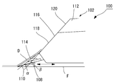
24 is a partially enlarged cross-sectional view of a
As shown in Fig. 24, in the floor
An
However, the
When the rolled bottom material D has a certain radius, it is impossible to continue to operate the
In view of the above-described phenomenon, the present invention has been made in view of the above-mentioned problems, and it is an object of the present invention to provide a floor material which is peeled off from the floor surface by a peeling blade does not reach the position of a worker holding the handle at the rear of the peeling machine body, And to provide a peeling machine.
Further, according to the present invention, it is not necessary to guide the floor material raised by hand by the auxiliary worker to the side of the peeling machine body, and the floor material is not caught on the mechanical parts of the surface of the peeling machine body, And to provide a floor material peeling machine capable of working and having improved working efficiency.
The present invention has been made in order to achieve the above-mentioned problems and objects in the prior art.
A floor material peeler of the present invention comprises a substantially box-shaped peeler main body configured to be movable by a wheel and a blade bracket disposed at a lower end of a front main frame of the peeler main body to support a peeling blade,
A flooring peeling machine for peeling a flooring adhered to a floor surface, the flooring being configured to peel the flooring material by a peeling blade by vibrating a blade bracket supporting the peeling blade by driving a driving mechanism built in the peeling machine body,
And a guide inclined surface for guiding the bottom material separated from the bottom surface by the peeling blade upward,
And a tilting angle between the bottom surface and the guide sloping face where the peeling edge of the bottom material peeled off from the bottom surface is contacted by the peeling edge gradually increases toward the upward direction.
With such a configuration, the bottom material separated from the bottom surface by the peeling edge is guided along the guide slope and ascends. In this case, since the angle of inclination between the guide slope and the bottom surface of the bottom material peeled off from the bottom surface by the peeling blade is set so as to gradually increase toward the upward direction, As shown in FIG.
Therefore, the floor material peeled from the bottom surface by the peeling blade does not reach the position of the worker holding the handle at the rear of the peeler main body, and does not interfere with the work.
Further, it is possible to provide a floor material peeling machine in which the continuous work can be performed without the concern that the work is interrupted because the bottom material does not catch on the mechanical parts of the peeler main body surface or the like.
Further, in the floor material peeler of the present invention,
Wherein the guide slope has a slope of a bracket on a front face of the blade bracket and a slope face of a main frame of a front face of the front body frame,
Wherein an angle of inclination? Between the inclined surface of the bracket and a bottom surface of the front surface of the blade bracket and an angle of inclination? Between the inclined surface of the main body frame and the bottom surface of the front main body frame are larger than the inclination angle? beta) is set,
And the inclination angle beta between the inclined surface of the main body frame and the bottom surface of the front main body frame gradually increases toward the upward direction.
With this configuration, the bottom material peeled off from the bottom surface F by the peeling blade is guided along the inclined surface of the bracket on the front surface of the blade bracket and guided along the inclined surface of the main frame of the front main body frame front face of the peeling machine main body .
In this case, the inclination angle? Between the inclined angle? Of the bracket on the front surface of the blade and the inclination angle? Between the inclined surface and the bottom surface of the front surface of the front body frame is set so that the inclination angle? (? <?).
Therefore, the bottom material separated from the bottom surface by the peeling blade is guided along the inclined surface of the bracket on the front surface of the blade bracket.
Since the inclination angle beta between the inclined surface of the main body frame and the bottom surface of the front main body frame is set so as to gradually increase toward the upward direction, the raised flooring guided along the inclined surface of the bracket on the front surface of the blade bracket, So that it is guided upward without being guided rearward like a conventional floor material peeling machine.
Therefore, the floor material peeled from the bottom surface by the peeling blade does not reach the position of the worker holding the handle at the rear of the peeler main body, and does not interfere with the work.
Further, it is possible to provide a floor material peeling machine in which the continuous work can be performed without the concern that the work is interrupted because the bottom material does not catch on the mechanical parts of the peeler main body surface or the like.
The floor stripper of the present invention is characterized in that the inclination angle beta between the inclined surface of the front surface of the front body frame and the bottom surface of the front surface of the front surface of the front body frame is gradually increased in multiple stages.
With this configuration, by the inclined surface of the main body frame on the front surface of the front main body frame formed so that the floor material peeled off from the bottom surface by the peeling edge is guided along the inclined surface of the bracket on the front surface of the blade bracket, It is guided upward without being guided rearward like a conventional floor material peeling machine.
Therefore, the floor material peeled off from the bottom surface by the peeling edge does not reach the position of the worker holding the handle at the rear of the peeler main body, and does not interfere with the work.
Further, it is possible to provide a floor material peeling machine in which the continuous work can be performed without the concern that the work is interrupted because the bottom material does not catch on the mechanical parts of the peeler main body surface or the like.
The floor material peeler of the present invention is characterized in that the inclination angle? Between the inclined surface of the bracket on the front surface of the blade bracket and the bottom surface of the inclined surface of the bracket on the front surface of the blade is gradually increased.
With this configuration, the bottom material separated from the bottom surface by the peeling blade is smoothly guided upward along the inclined plane of the bracket formed on the front surface of the blade bracket formed so that the inclination angle? Gradually increases gradually.
The floor material peeler of the present invention is characterized in that a guide plate member is provided on the inclined surface of the main body frame on the front surface of the front main body frame and has a guide slope for guiding the peeled floor material to the side of the peeling machine main body.
With this configuration, the floor material, which is peeled off from the floor surface by the peeling edge and guided to the slope face of the main frame of the front face of the front body frame, is raised along the guide slope of the guide plate member formed on the slope face of the main frame of the front face of the front body frame, The peeled bottom material is guided to the side of the peeler main body.
Therefore, it is not necessary to guide the floor material raised by hand by the auxiliary worker to the side of the peeling machine body like the conventional flooring peeling machine, and the flooring material peeled off from the floor surface by the peeling- The worker does not reach the position of the worker who is holding the work, and does not interfere with the work.
Further, it is possible to provide a floor material peeling machine in which the continuous work can be performed without the concern that the work is interrupted because the bottom material does not catch on the mechanical parts of the peeler main body surface or the like.
Further, the floor material peeler of the present invention is characterized in that the guide slope of the guide plate member is a guide plate member having a left guide slope for guiding the peeled flooring material to the left side room in the traveling direction of the peeler main body.
As described above, the guide slope of the guide plate member may be a guide plate member formed with a left guide slope for guiding the peeled flooring material to the left side room in the moving direction of the peeling machine body.
The floor material peeler of the present invention is characterized in that the guide slope of the guide plate member is a guide plate member formed with a right guide slope for guiding the peeled flooring material to the right side room in the traveling direction of the peeler main body.
As described above, the guide slope of the guide plate member may be a guide plate member formed with a right guide slope for guiding the peeled flooring material to the right side room in the traveling direction of the peeler main body.
The flooring peeler of the present invention is characterized in that the guide slope of the guide plate member is a guide plate member formed with a left guide slope and a right guide slope for guiding the peeled bottom material to the right and left sides in the traveling direction of the peeler main body .
With such a configuration, it is not necessary to guide the floor material raised by hand by the auxiliary work source like the conventional floor material peeling machine to the side of the peeling machine body, and the floor material peeled off from the floor surface by the peeling- And is guided to the left and right sides of the peeler body by the guide slopes.
Therefore, the floor material peeled from the bottom surface by the peeling blade does not reach the position of the worker holding the handle at the rear of the peeler main body, and does not interfere with the work.
Further, it is possible to provide a floor material peeling machine in which the continuous work can be performed without the concern that the work is interrupted because the bottom material does not catch on the mechanical parts of the peeler main body surface or the like.
Further, the floor material peeler of the present invention is characterized in that the guide plate member is configured to be rotatable in the left-right direction.
Thus, when the guide plate member is configured to be rotatable in the left and right direction, the floor material separated from the floor surface by the peeling blade can be guided to the right and left sides of the peeling machine body at a free angle.
Further, the floor material peeler of the present invention is characterized in that a guide mechanism for guiding the peeled flooring material positioned in front of the wheel to left and right sides in the traveling direction of the peeler main body is provided.
When the finely divided floor material D is peeled off from the bottom surface F and comes to the front of the wheel, the wheel may climb onto the finely divided floor material D in some cases.
As a result, the peeling blade mounted on the blade bracket does not become horizontal but slides on the surface with respect to the bottom material D of the bottom surface F, and as a result, The floor material D is not peeled off from the bottom surface F.
Further, when the wheels are mounted on the finely divided floor material D, the rear portion of the peeling machine body is in a floating state. As a result, the cutting edge of the peeling edge with respect to the bottom surface F deviates from the bottom surface F by a predetermined angle (for example, 15 to 30 degrees) at which the bottom material D is easily peeled off, It is not peeled off.
On the other hand, since the floor material peeling machine of the present invention is provided with the guide mechanism, the finely divided floor material D is peeled off from the bottom surface F and is guided to the left and right sides of the peeling machine body, (D) is not stepped on the wheel.
Accordingly, even when the finely divided floor material D peeled off from the bottom surface F comes to the front of the wheel, the wheel does not step on the finely divided floor material D.
In addition, since the finely divided floor material D is not stepped on the wheel, the peeler main body is always horizontal without being tilted. As a result, the peeling blade mounted on the blade bracket is always horizontal, It is possible to reliably separate the floor material D from the floor surface F without slipping on the surface with respect to the floor D.
In the floor material peeler of the present invention, the slope angle A between the peeling edge and the bottom surface is in the range of 15 to 30,
Wherein an angle of inclination? Between the inclined surface of the bracket and the bottom surface of the blade bracket is set to be larger than a range of 5 to 20 degrees with respect to the inclination angle A between the separation edge and the bottom surface.
Further, the floor material peeler of the present invention is characterized in that the blade bracket on which the peeling blade is mounted is configured to horizontally move and vibrate in the front-rear direction.
According to the present invention, the bottom material separated from the bottom surface by the peeling edge is guided along the guiding sloping surface to rise. In this case, since the angle of inclination between the guide sloping face of the bottom material peeled off from the bottom face by the peeling edge and the bottom face is set so as to gradually increase upward, And is guided upward.
Therefore, the floor material peeled from the bottom surface by the peeling blade does not reach the position of the worker holding the handle at the rear of the peeler main body, and does not interfere with the work.
Further, it is possible to provide a floor material peeling machine in which the continuous work can be performed without the concern that the work is interrupted because the bottom material does not catch on the mechanical parts of the peeler main body surface or the like.
According to the present invention, the bottom material peeled off from the bottom surface F by the peeling blade is guided along the inclined surface of the bracket on the front surface of the blade bracket and guided along the inclined surface of the main body frame on the front main body frame front side of the peeling machine main body .
In this case, the inclination angle? Between the inclined angle? Of the bracket on the front surface of the blade and the inclination angle? Between the inclined surface and the bottom surface of the front surface of the front body frame is set so that the inclination angle? (? <?).
Therefore, the floor material D peeled off from the bottom surface F by the peeling edge is guided along the inclined plane of the bracket on the front face of the blade bracket.
Since the inclination angle beta between the inclined surface of the main frame and the bottom surface of the front main body frame gradually increases toward the upward direction, the floor material guided along the inclined surfaces of the brackets on the front surface of the blade bracket, It is guided upward by the inclined surface without being guided rearward like a conventional floor material peeling machine.
Therefore, the floor material peeled from the bottom surface by the peeling blade does not reach the position of the worker holding the handle at the rear of the peeler main body, and does not interfere with the work.
Further, it is possible to provide a floor material peeling machine in which the continuous work can be performed without the concern that the work is interrupted because the bottom material does not catch on the mechanical parts of the peeler main body surface or the like.
According to the present invention, the floor material is peeled off from the floor surface by the peeling edge and guided to the inclined face of the main frame of the front body frame, and the raised floor material is guided along the guide slope of the guide plate member formed on the inclined face of the main body frame, Whereby the peeled bottom material is guided to the side of the peeler main body.
Therefore, it is not necessary for the auxiliary worker to be guided to the side of the peeler body by peeling off the hand by the hand, and the flooring material peeled off from the bottom surface by the peeling blade is held by the worker holding the handle at the back of the peeler body. So that the work does not interfere with the operation.
Further, it is possible to provide a floor material peeling machine in which the continuous work can be performed without the concern that the work is interrupted because the bottom material does not catch on the mechanical parts of the peeler main body surface or the like.
BRIEF DESCRIPTION OF THE DRAWINGS FIG. 1 is a schematic side view of a floor stripper of the present invention. FIG.
Fig. 2 is a view of the floor material peeling machine shown in Fig. 1 viewed from the direction of arrow A. Fig.
Fig. 3 is a top view of the floor material peeler shown in Fig. 1. Fig.
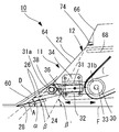
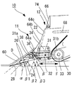
4 is a partially enlarged view of Fig.
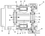
5 is a partially enlarged side view showing an example of a driving mechanism for horizontally moving (vibrating) the
Fig. 6 is a top view of Fig. 5. Fig.
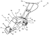
7 is a perspective view of the floor material peeler shown in Fig.
8 is a partially enlarged side view of a floor material peeler according to another embodiment of the present invention.
9 is a side view schematically showing a floor material peeling machine according to another embodiment of the present invention.
Fig. 10 is a view of the floor material peeling machine shown in Fig. 9 viewed from the direction of arrow A. Fig.
11 is a top view of the floor material peeler shown in Fig.
12 is a side view schematically showing a floor material peeling machine according to another embodiment of the present invention.
13 is a partially enlarged view of Fig.
14 is a top view of the floor material peeler shown in Fig.
15 is a side view schematically showing a flooring peeler according to another embodiment of the present invention.
Fig. 16 is a view of the floor material peeling machine shown in Fig. 15 viewed from the direction of arrow A. Fig.
17 is a top view of the floor material peeler shown in Fig.
18 is a top view schematically showing a floor material peeling machine according to still another embodiment of the present invention.
19 is a top view schematically showing a floor material peeler according to another embodiment of the present invention.
Fig. 20 is a side view similar to Fig. 1, schematically showing a floor stripper of another embodiment of the present invention.
21 is a bottom view of the floor material peeler shown in Fig.
FIG. 22 is a side view schematically showing a general structure of a conventional floor-peeling machine of a hand-push type. FIG.
23 is a partially enlarged side view of the conventional flooring peeler shown in Fig.
24 is a partially enlarged cross-sectional view of a
DESCRIPTION OF THE PREFERRED EMBODIMENTS Hereinafter, embodiments of the present invention will be described in detail with reference to the drawings.
(Example 1)
Fig. 1 is a side view schematically showing the floor material peeling machine of the present invention, Fig. 2 is a view of the floor material peeling machine shown in Fig. 1 viewed from the direction of arrow A, Fig. 3 is a top view of the floor material peeling machine shown in Fig. Fig. 5 is a partially enlarged side view showing an example of a driving mechanism for horizontally moving (vibrating) the
In Figs. 1 to 3 and Fig. 7,
As shown in Fig. 1, the floor material peeler of the present invention has a substantially box-shaped peeler
Of course, it may be a floor
A
1 and 3, a
More specifically, in a state in which the
On the other hand, while the
Conversely, in the state where the
While the
An
A
5 is a partially enlarged side view showing an example of a driving mechanism for horizontally moving (vibrating) the
5 and 6, a
5 and 6, a
A
A
The rotation drive
5 and 6, the rotation shaft of the
With this configuration, by the rotation of the rotation drive
The driving
Since the one
That is, the
The vibration of the
1, in order to adjust the tension of the
1, 3 and 4, the
That is, the engagement portion of the
Thus, the cutting edge of the peeling
A
1 and 3, in the
The inclined angle between the
With this configuration, the floor material D peeled off from the bottom surface F by the peeling
The floor material D peeled from the bottom surface F by the
In addition, it is possible to provide a floor material peeling machine in which continuous operation can be performed without fear of interruption of work because the floor material D is not caught on mechanical parts of the surface of the peeling
In this case, in the
1 and 3, the floor material D peeled off from the bottom surface F by the
4, in the
The floor material D peeled off from the bottom surface F by the
In the
4, in the
The inclination angle beta between the
The raised floor material D guided along the
The floor material D peeled off from the bottom surface F by the
Further, it is possible to provide the floor
As shown in Figs. 1 and 3, on the left and right side surfaces 54a and 54b of the peeling
1 and 3, a
In this case, the inclination angle? Between the main body frame inclined
However, after the floor material D peeled from the bottom surface F by the
4, the inclination angle? Between the
8, the body frame inclined
On the other hand, although the number of multi-stages is three in the present embodiment, the number, length, and the like are not particularly limited. Likewise, the number, the length, and the like of the multi-stage are not particularly limited in the case of multi-stage formation of the body frame inclined
In this case, the body frame inclined
Although not shown, the bracket inclined
The floor material D peeled off from the bottom face F by the peeling
Although not shown, the inclination angle? 'Between the weight portion inclined
4, the inclination angle A between the peeling
1, the engaging portions of the height adjusting levers 52 are fastened to a plurality of
In this case, the inclination angle between the
(Example 2)
Fig. 9 is a side view schematically showing a floor material peeling machine according to another embodiment of the present invention, Fig. 10 is a view of the floor material peeling machine shown in Fig. 9 viewed from the direction of arrow A and Fig. 11 is a top view of the floor material peeling machine shown in Fig. 9 .
The floor
In the
An
The floor material D peeled off from the bottom surface F by the peeling
The width of the
20 and 21 to be described later (in the directions of the left and right side surfaces 54a and 54b of the peeling machine body 12) in the advancing direction of the peeling
(Example 3)
FIG. 12 is a side view schematically showing a floor material peeling machine according to still another embodiment of the present invention, FIG. 13 is a partially enlarged view of FIG. 12, and FIG. 14 is a top view of the floor material peeling machine shown in FIG.
The floor
12 and 13, the inclination angle A between the peeling
However, the inclination angle beta between the main frame frame inclined
That is, in the
13, the peeling end portion D1 of the floor material D, which is peeled off from the bottom face F by the peeling
9 to 11, the width of the peeling
The
The width of the
20 and 21 to be described later (in the directions of the left and right side surfaces 54a and 54b of the peeling machine body 12) in the advancing direction of the peeling
(Example 4)
15 is a side view schematically showing a floor material peeling machine according to still another embodiment of the present invention, Fig. 16 is a view of the floor material peeling machine shown in Fig. 15 viewed from the direction of arrow A, Fig. 17 is a top view of the floor material peeling machine shown in Fig. to be.
The floor
15 to 17, the peeled bottom material D is adhered to the peeler
That is, in the
As shown in Figs. 15 to 17, the left side guiding
The
With this configuration, it is not necessary to guide the floor material D, which has been raised by peeling the auxiliary worker by hand like the conventional floor material peeling machine, to the side of the peeling
The floor material D peeled from the bottom surface F by the
Further, it is possible to provide the floor
Although not shown, the
When the
In the
18, the guiding
19, only the right
Further, though not shown, it is also possible to provide one guide sloping surface on one
The sloping surface for guiding the peeled bottom material D to the left side (
(Example 5)
Fig. 20 is a side view similar to Fig. 1, schematically showing a floor material peeling machine according to still another embodiment of the present invention, and Fig. 21 is a bottom view of the floor material peeling machine shown in Fig.
The floor
On the other hand, when the finely divided floor material D is peeled off from the bottom face F and comes to the front of the
As a result, the
The
20 and 21, when the finely divided floor material D is peeled off from the bottom surface F and comes to the front of the
20 and 21, the
21, a
And a substantially L-shaped
20, guide
The
The adjusting
The adjustment of the height of the peeler
As a result, when the finely divided floor material D comes to the front of the
In this case, the height adjustment of the peeler
The
21, the angle? Formed by the
In this case, the
On the other hand, in the present embodiment, the
Therefore, in the
Thereby, even when the finely divided floor material D peeled off from the bottom surface F comes to the front of the
The peeling
For example, in the second embodiment, the
However, it is also possible to provide the
In the
However, not only the longitudinal vibration of the
The
Although the
For example, the present invention can be applied to a floor surface made of a resin tile such as a vinyl chloride material adhered to a floor, a soft sheet material such as a CF sheet or a linoleum sheet, an epoxy resin or a urethane resin, , A hard tile composed of stone and the like, and a floor material composed of wood such as flooring used in, for example, ondol, etc., can be applied to a floor material peeling machine for continuously peeling off the floor material.
10, 100, 200 Flooring stripper
11 guide slope
12, 102 separator body
14, 104 wheels
16, 106 handle
16a clutch lever
18 switch
20 operator panel
22, 116 Front body frame
24, 108 blade bracket
24a inclined flange
26, 74, 90,
28, 110 Removal day
30 rotation transmission pulley
31 drive rod
31a once
31b
32 horizontal guide member
33 Eccentric shaft
34 Guide bracket
35 Bearings
36 base end
38, 50a, 82 pivot axis
40 drive motor
42 rotation drive pulley
44 rotary drive belt
46 Sliding groove
48 Tension adjuster
50 wheel support bracket
52 Control lever
54a, 54b side
56 Adjusting Ball
58, 112 weight portion
60, 114 Bracket slope
64, 118 Body Frame Slope
66, 120 Weighted slope
68 Carrying handle
70 guide plate member
72 guide slope
72a left guide slope
72b right guide slope
72c, 72d end
80 guide mechanism
84 Guide bracket
86 Guide Flange
88 guide blade
92 Guide groove
92a latching groove
94 Adjusting pin
202 Machine body
204 Blade attachment body
206 sliding face
208 Attachment
210 blade
212 guide surface
D flooring
D1 peeling end
F floor
α, β, β ', A Tilt angle
Claims (18)
And a blade bracket disposed at a lower end of the front main body frame of the peeler main body to support the peeling blade,
A flooring peeling machine for peeling a flooring adhered to a floor surface, the flooring being configured to peel the flooring material by a peeling blade by vibrating a blade bracket supporting the peeling blade by driving a driving mechanism built in the peeling machine body,
And a guide inclined surface for guiding the bottom material separated from the bottom surface by the peeling blade upward,
Wherein the slope angle between the guide slope and the bottom surface, at which the peeling edge of the bottom material separated from the bottom surface by the peeling edge abuts, gradually increases toward the upper side.
Wherein the guide inclined surface includes a slant surface of the bracket on the front surface of the blade bracket and a slant surface of the main body frame on the front surface of the front main body frame,
Wherein an angle of inclination? Between the inclined surface of the bracket and a bottom surface of the front surface of the blade bracket and an angle of inclination? Between the inclined surface of the main body frame and the bottom surface of the front main body frame are larger than the inclination angle? beta) is set,
Wherein a slope angle? Between an inclined surface of the main frame and a bottom surface of the front main frame is gradually increased toward the upper side.
Wherein a slope angle of the body frame at the front face of the front body frame is formed such that an inclination angle beta between the slope face of the body frame at the front face of the front body frame and the bottom face gradually increases in a multistage manner.
Wherein a slope angle of the bracket on the front surface of the blade bracket is formed such that an inclination angle a between the slope surface of the bracket on the front surface of the blade and the bottom surface gradually increases in multiple stages.
Wherein a guide plate member is provided on an inclined surface of the main body frame on the front surface of the front body frame and on which a guide slope for guiding the peeled bottom material to the side of the peeling machine body is formed.
Wherein the guide inclined face of the guide plate member is a guide plate member having a left guide slope for guiding the peeled bottom material to the left side room in the traveling direction of the main body of the peeling machine.
Wherein the guide sloping surface of the guide plate member is a guide plate member having a right guide slope for guiding the peeled bottom material to the right chamber in the direction of travel of the peeler main body.
Wherein the guide sloping surface of the guide plate member is a guide plate member formed with a left guide sloped surface and a right guide sloped surface for guiding the peeled bottom material to left and right sides in the traveling direction of the main body of the peeler.
Wherein the guide plate member is configured to be rotatable in the left-right direction.
And a guide mechanism for guiding the peeled bottom material located in front of the wheel to left and right sides in the traveling direction of the peeler main body.
The inclination angle A between the peeling edge and the bottom surface is in the range of 15 to 30,
Wherein a slope angle? Between the inclined plane of the bracket on the front face of the blade and the bottom face is set to be larger than a slope angle A between 5 占 and 20 占 between the peeling blade and the bottom face.
And the blade bracket on which the separation blade is mounted is horizontally moved and vibrated in the forward and backward directions.
And a blade bracket disposed at a lower end of the front main body frame of the peeler main body to support the peeling blade,
A flooring peeling machine for peeling a flooring adhered to a floor surface, the flooring being configured to peel the flooring material by a peeling blade by vibrating a blade bracket supporting the peeling blade by driving a driving mechanism built in the peeling machine body,
Wherein a guide plate member is provided on an inclined surface of the main body frame on the front surface of the front body frame and on which a guide slope for guiding the peeled bottom material to the side of the peeling machine body is formed.
Wherein the guide inclined face of the guide plate member is a guide plate member having a left guide slope for guiding the peeled bottom material to the left side room in the traveling direction of the main body of the peeling machine.
Wherein the guide sloping surface of the guide plate member is a guide plate member having a right guide slope for guiding the peeled bottom material to the right chamber in the direction of travel of the peeler main body.
Wherein the guide sloping surface of the guide plate member is a guide plate member formed with a left guide sloped surface and a right guide sloped surface for guiding the peeled bottom material to left and right sides in the traveling direction of the main body of the peeler.
Wherein the guide plate member is configured to be rotatable in the left-right direction.
And a guide mechanism for guiding the peeled bottom material located in front of the wheel to left and right sides in the traveling direction of the peeler main body.
Applications Claiming Priority (4)
| Application Number | Priority Date | Filing Date | Title |
|---|---|---|---|
| JPJP-P-2015-251380 | 2015-12-24 | ||
| JP2015251380 | 2015-12-24 | ||
| JP2016033107A JP6709556B2 (en) | 2015-12-24 | 2016-02-24 | Floor material peeling machine |
| JPJP-P-2016-033107 | 2016-02-24 |
Publications (1)
| Publication Number | Publication Date |
|---|---|
| KR20170076525A true KR20170076525A (en) | 2017-07-04 |
Family
ID=59272587
Family Applications (1)
| Application Number | Title | Priority Date | Filing Date |
|---|---|---|---|
| KR1020160028787A KR20170076525A (en) | 2015-12-24 | 2016-03-10 | Floor material stripping machine |
Country Status (2)
| Country | Link |
|---|---|
| JP (1) | JP6709556B2 (en) |
| KR (1) | KR20170076525A (en) |
Families Citing this family (1)
| Publication number | Priority date | Publication date | Assignee | Title |
|---|---|---|---|---|
| CN110644742B (en) * | 2019-09-27 | 2021-07-02 | 广东博智林机器人有限公司 | Floor push-in mechanism and floor installation robot |
Family Cites Families (10)
| Publication number | Priority date | Publication date | Assignee | Title |
|---|---|---|---|---|
| US3726565A (en) * | 1971-05-28 | 1973-04-10 | W Oliverius | Material stripping apparatus and blade |
| JPS5922859U (en) * | 1982-08-03 | 1984-02-13 | 株式会社日本技術センタ− | flooring stripping machine |
| JPS6059262A (en) * | 1983-09-09 | 1985-04-05 | 東海機器工業株式会社 | Method and apparatus for releasing coating material |
| JPH0242825Y2 (en) * | 1985-10-29 | 1990-11-15 | ||
| JP2540007Y2 (en) * | 1991-06-20 | 1997-07-02 | 有限会社インテリアサロン藤原 | Floor material stripping machine |
| JPH0648055Y2 (en) * | 1991-09-24 | 1994-12-07 | 田中工業株式会社 | Self-propelled vehicle for floor material peeling |
| JP2502492Y2 (en) * | 1993-10-08 | 1996-06-26 | 哲人 水野 | Floor material peeling machine |
| JP4653872B2 (en) * | 2000-06-27 | 2011-03-16 | 株式会社ライナックス | Pushed floor stripper |
| JP3871319B2 (en) * | 2002-05-23 | 2007-01-24 | 有限会社インテリアサロン藤原 | Floor material peeling method |
| JP2008202309A (en) * | 2007-02-20 | 2008-09-04 | Okabe Tekkosho:Kk | Floor material separator |
-
2016
- 2016-02-24 JP JP2016033107A patent/JP6709556B2/en active Active
- 2016-03-10 KR KR1020160028787A patent/KR20170076525A/en not_active Application Discontinuation
Also Published As
| Publication number | Publication date |
|---|---|
| JP2017120008A (en) | 2017-07-06 |
| JP6709556B2 (en) | 2020-06-17 |
Similar Documents
| Publication | Publication Date | Title |
|---|---|---|
| US6135566A (en) | Self-propelled floor stripper | |
| US4009908A (en) | Carpet and tile stripper | |
| US4162809A (en) | Oscillating carpet and tile stripper | |
| US2874946A (en) | Floor covering stripper | |
| KR20170076525A (en) | Floor material stripping machine | |
| KR20170136437A (en) | Combine | |
| US6711971B1 (en) | Roofing removal apparatus | |
| JP5395965B2 (en) | Sheet material peeling apparatus and peeling method | |
| US20020108720A1 (en) | Apparatus for the removal of floor coverings | |
| JP2012217358A (en) | Sowing machine | |
| KR101104871B1 (en) | Device for brushing the non-slip of steps | |
| JP2017089110A (en) | U-rib cutting method | |
| JP5913529B2 (en) | Shot blasting equipment | |
| JP5234935B2 (en) | snowblower | |
| JP6979834B2 (en) | combine | |
| JP5586249B2 (en) | Passenger conveyor step cleaning method | |
| JP2540007Y2 (en) | Floor material stripping machine | |
| US5868053A (en) | Carpet cutting apparatus and method | |
| JP4648776B2 (en) | Interior material peeling machine | |
| JP2975305B2 (en) | Cutting equipment | |
| JPH0242825Y2 (en) | ||
| JP5131653B2 (en) | Attitude maintenance device for furrow work machine | |
| JP4106259B2 (en) | Snow blower height adjustment device | |
| JP6944150B2 (en) | Sediment crusher | |
| JP6900042B2 (en) | Grinding device |
Legal Events
| Date | Code | Title | Description |
|---|---|---|---|
| A201 | Request for examination | ||
| E902 | Notification of reason for refusal | ||
| E601 | Decision to refuse application |