KR20170074858A - Controlled Deformations in Metallic Pieces - Google Patents
Controlled Deformations in Metallic Pieces Download PDFInfo
- Publication number
- KR20170074858A KR20170074858A KR1020177008535A KR20177008535A KR20170074858A KR 20170074858 A KR20170074858 A KR 20170074858A KR 1020177008535 A KR1020177008535 A KR 1020177008535A KR 20177008535 A KR20177008535 A KR 20177008535A KR 20170074858 A KR20170074858 A KR 20170074858A
- Authority
- KR
- South Korea
- Prior art keywords
- region
- mechanical
- strength
- mechanical low
- edges
- Prior art date
Links
Images
Classifications
-
- C—CHEMISTRY; METALLURGY
- C21—METALLURGY OF IRON
- C21D—MODIFYING THE PHYSICAL STRUCTURE OF FERROUS METALS; GENERAL DEVICES FOR HEAT TREATMENT OF FERROUS OR NON-FERROUS METALS OR ALLOYS; MAKING METAL MALLEABLE, e.g. BY DECARBURISATION OR TEMPERING
- C21D1/00—General methods or devices for heat treatment, e.g. annealing, hardening, quenching or tempering
- C21D1/34—Methods of heating
-
- C—CHEMISTRY; METALLURGY
- C21—METALLURGY OF IRON
- C21D—MODIFYING THE PHYSICAL STRUCTURE OF FERROUS METALS; GENERAL DEVICES FOR HEAT TREATMENT OF FERROUS OR NON-FERROUS METALS OR ALLOYS; MAKING METAL MALLEABLE, e.g. BY DECARBURISATION OR TEMPERING
- C21D9/00—Heat treatment, e.g. annealing, hardening, quenching or tempering, adapted for particular articles; Furnaces therefor
- C21D9/0068—Heat treatment, e.g. annealing, hardening, quenching or tempering, adapted for particular articles; Furnaces therefor for particular articles not mentioned below
-
- B—PERFORMING OPERATIONS; TRANSPORTING
- B23—MACHINE TOOLS; METAL-WORKING NOT OTHERWISE PROVIDED FOR
- B23K—SOLDERING OR UNSOLDERING; WELDING; CLADDING OR PLATING BY SOLDERING OR WELDING; CUTTING BY APPLYING HEAT LOCALLY, e.g. FLAME CUTTING; WORKING BY LASER BEAM
- B23K26/00—Working by laser beam, e.g. welding, cutting or boring
- B23K26/0093—Working by laser beam, e.g. welding, cutting or boring combined with mechanical machining or metal-working covered by other subclasses than B23K
-
- C—CHEMISTRY; METALLURGY
- C21—METALLURGY OF IRON
- C21D—MODIFYING THE PHYSICAL STRUCTURE OF FERROUS METALS; GENERAL DEVICES FOR HEAT TREATMENT OF FERROUS OR NON-FERROUS METALS OR ALLOYS; MAKING METAL MALLEABLE, e.g. BY DECARBURISATION OR TEMPERING
- C21D1/00—General methods or devices for heat treatment, e.g. annealing, hardening, quenching or tempering
- C21D1/34—Methods of heating
- C21D1/42—Induction heating
-
- H—ELECTRICITY
- H05—ELECTRIC TECHNIQUES NOT OTHERWISE PROVIDED FOR
- H05B—ELECTRIC HEATING; ELECTRIC LIGHT SOURCES NOT OTHERWISE PROVIDED FOR; CIRCUIT ARRANGEMENTS FOR ELECTRIC LIGHT SOURCES, IN GENERAL
- H05B6/00—Heating by electric, magnetic or electromagnetic fields
- H05B6/02—Induction heating
- H05B6/10—Induction heating apparatus, other than furnaces, for specific applications
- H05B6/101—Induction heating apparatus, other than furnaces, for specific applications for local heating of metal pieces
-
- C—CHEMISTRY; METALLURGY
- C21—METALLURGY OF IRON
- C21D—MODIFYING THE PHYSICAL STRUCTURE OF FERROUS METALS; GENERAL DEVICES FOR HEAT TREATMENT OF FERROUS OR NON-FERROUS METALS OR ALLOYS; MAKING METAL MALLEABLE, e.g. BY DECARBURISATION OR TEMPERING
- C21D2221/00—Treating localised areas of an article
-
- Y—GENERAL TAGGING OF NEW TECHNOLOGICAL DEVELOPMENTS; GENERAL TAGGING OF CROSS-SECTIONAL TECHNOLOGIES SPANNING OVER SEVERAL SECTIONS OF THE IPC; TECHNICAL SUBJECTS COVERED BY FORMER USPC CROSS-REFERENCE ART COLLECTIONS [XRACs] AND DIGESTS
- Y02—TECHNOLOGIES OR APPLICATIONS FOR MITIGATION OR ADAPTATION AGAINST CLIMATE CHANGE
- Y02P—CLIMATE CHANGE MITIGATION TECHNOLOGIES IN THE PRODUCTION OR PROCESSING OF GOODS
- Y02P10/00—Technologies related to metal processing
- Y02P10/25—Process efficiency
Landscapes
- Chemical & Material Sciences (AREA)
- Engineering & Computer Science (AREA)
- Physics & Mathematics (AREA)
- Mechanical Engineering (AREA)
- Organic Chemistry (AREA)
- Crystallography & Structural Chemistry (AREA)
- Materials Engineering (AREA)
- Metallurgy (AREA)
- Thermal Sciences (AREA)
- Electromagnetism (AREA)
- Optics & Photonics (AREA)
- Plasma & Fusion (AREA)
- Body Structure For Vehicles (AREA)
- Heat Treatment Of Articles (AREA)
- Shaping Metal By Deep-Drawing, Or The Like (AREA)
- Vibration Dampers (AREA)
Abstract
본 발명은 차량 제조를 위한, 길이 방향(A)을 따라 전체적으로 신장된 형상의 금속 부재(P)에 관한 것으로서, 부재의 2 개의 벽(10,20,22,50)들의 교선에서 길이 방향을 따라서 연장된 적어도 하나의 가장자리(11, 13, 21, 23) 및, 부재의 동체의 나머지보다 약한 기계적 강도를 가진 적어도 하나의 영역(100)을 포함하고, 적어도 하나의 영역(100)은 부재의 국부적인 열적 제어를 통하여 형성된다. 기계적인 저 강도 영역은 가장자리(11,13,21,23)를 따라서 파동을 이루어 상기 가장자리를 형성하는 벽(10,20,22,50)들 각각에서 적어도 주로 번갈아서 연장되는 것을 특징으로 한다. 본 발명은 또한 부재의 제조 방법에 관한 것이다. The present invention relates to a metallic member (P) of a generally elongated shape along the longitudinal direction (A) for vehicle manufacture, characterized in that it comprises a first wall (10, 20, 22, 50) And at least one region (100) having a mechanical strength less than that of the rest of the member's body, wherein the at least one region (100) comprises at least one region (11) Thermal control. The mechanical low intensity region is characterized in that it waves along the edges (11, 13, 21, 23) alternately at least largely in each of the walls (10, 20, 22, 50) forming the edge. The present invention also relates to a method of manufacturing an element.
Description
본 출원은 2014 년 9 월 22 일에 출원된 프랑스 특허 출원 1458913 및 유럽 특허 출원 14 382 354.0 의 우선권을 주장한다.This application claims priority from French patent application 1458913 and European patent application 14 382 354.0, filed on September 22, 2014.
본 발명은 금속 프레임의 제조와 관련된 금속 부재들의 분야에 관한 것으로서, 상세하게는 프레임 또는 차량 차체에 관한 것이다. BACKGROUND OF THE INVENTION 1. Field of the Invention The present invention relates to the field of metal members associated with the manufacture of metal frames, and more particularly to a frame or vehicle body.
본 발명의 목적은 충돌중에 금속 부재들의 변형 모드 및 강도 특성들을 정확하게 제어하기 위한 수단을 제공하는 것이다. It is an object of the present invention to provide means for precisely controlling the deformation mode and strength characteristics of metal members during impact.
금속 부재의 주 동체의 강도보다 약하게 기계적 강도의 특성을 개별 제어함으로써, 길이를 따라서 분포된, 연속적인 영역들을 포함하는 신장된 금속 부재를 제조하는 다양한 방법들이 제안되었다. Various methods for manufacturing an elongated metal member including continuous regions distributed along the length have been proposed by individually controlling the characteristics of the mechanical strength weaker than the strength of the main body of the metal member.
종래 기술에 따르면, 적용예에 따라서 적절한 단면을 얻도록, 통상적으로 열에 의하여 차후에 형상화되는 평탄한 금속 시트로부터 금속 부재들이 통상적으로 제작된다. 이러한 유형의 단면을 가진 특히 비 제한적이지만 바람직한 예는 전체적으로 모자 형상(hat shaped)의 섹션으로서, 이것은 저부에 전체적으로 횡방향으로 배치된 개별의 벽에 의하여 양쪽 측부들에서 연장되는 부재의 저부 부분을 포함하고, 각각의 벽들은, 외측을 향하면서 전체적으로 저부에 보통 평행한 플랜지에 의하여, 부재의 저부에 대향한 단부상에서 연장된다. 이러한 부재들의 단면은 길이를 따라서 변화될 수 있다. 이러한 부재들은 전체적으로 예를 들어 고정 수단 및 장착 인터페이스를 포함하지만, 플랜지들에 형성된 고정 구멍들의 형상에 제한되지 않는다. According to the prior art, metallic members are conventionally fabricated from flat metal sheets which are subsequently shaped by heat, usually to obtain the appropriate cross section according to the application. A particularly but non-limiting but preferred example of this type of cross section is a hat-shaped section as a whole which includes a bottom portion of a member extending from both sides by a separate wall disposed generally transversely to the bottom And each of the walls extends on an end opposite to the bottom of the member, generally by a flange generally parallel to the bottom, facing outward. The cross-section of these members may vary along their length. Such members generally include, for example, fixing means and mounting interface, but are not limited to the shape of the fixing holes formed in the flanges.
제어되는 냉각 회로를 가진 스탬핑 툴(stamping tool)을 통하여 가열된 블랭크를 차후에 형상화시키기 위하여 오스테나이트 천이 온도(austenitic transition temperature) 보다 높은 온도에서 금속 블랭크를 로(furnace)에서 가열하는 다른 방법들이 제안되었다. 스탬핑 툴은 드로우잉된 금속 블랭크와의 접촉 면적을 제한하도록 형상화된다. 결과적으로, 냉각된 스탬핑 툴과 접촉하는 금속 부재의 영역들은 마르텐사이트 상(martensitic phase)으로의 변환이 수행되고 예를 들어 적어도 1300 MPa 와 같고 통상적으로 1400 MPa 보다 높은 인장 강도인, 기계적인 고 강도를 나타내는 반면에, 스탬핑 공구와 직접 접촉하지 않아서 공기와 접촉 상태로 유지되는 금속 부재의 영역들은 덜 냉각되고, 오스테나이트 상과 마르텐사이트 상 사이의 즉각적인 상 변환이 수행되어 궁극적으로 기계적인 저 강도를 가지게 되며, 예를 들어 1000 MPa 보다 작은 인장 강도를 가진다. 그러한 기계적 저 강도 영역들은 상이한 조성들에 대응하며, 예를 들어, 퍼릴라이트(perlite), 페라이트(ferrite), 배이나이트(bainite) 및 어닐링된 마스텐사이트(annealed martensite)의 혼합물에 해당된다. Other methods have been proposed for heating the metal blank in a furnace at a temperature higher than the austenitic transition temperature to subsequently shape the heated blank through a stamping tool with a controlled cooling circuit . The stamping tool is shaped to limit the contact area with the drawn metal blank. As a result, regions of the metal member in contact with the cooled stamping tool are subjected to a transformation to a martensitic phase and are subjected to mechanical high strength, for example tensile strengths of at least 1300 MPa and typically greater than 1400 MPa While areas of the metal member that are not in direct contact with the stamping tool and remain in contact with air are less cooled and an immediate phase transformation between the austenite phase and the martensite phase is performed to ultimately provide mechanical low strength And has a tensile strength less than, for example, 1000 MPa. Such mechanical low strength regions correspond to different compositions and correspond, for example, to a mixture of perlite, ferrite, bainite and annealed martensite.
상기 언급된 방법의 한가지 예는 유럽 출원 EP 2209696 에 개시되어 있는데, 이것은 2 개의 상보적인 드로우잉 부재(drawing members)를 포함하는 툴을 통한 고온 드로우잉 방법을 개시하며, 드로우잉 부재들은 적어도 국부적으로 냉각되고 형상화되어야 하는 부재가 상기 드로우잉 부재들 사이에서 소망의 경화에 도달할 때까지 유지된다. One example of the above-mentioned method is disclosed in European application EP 2209696, which discloses a high temperature draw ing method through a tool comprising two complementary drawing members, wherein the draw ing elements are at least locally The member to be cooled and shaped is held between the drawing members until the desired curing is reached.
부재의 너무 빠른 냉각을 방지하도록 상이한 수단이 구현될 수 있으며, 따라서 국부적인 경화를 회피할 수 있다. 스탬핑 툴에서 부재의 급속 냉각을 방지하는 이러한 수단들중 일부는 드로우잉 부재들의 특정 부분들의 가열 수단의 형태이거나 또는 상기 드로우잉 부재들에 제공된 인서트 또는 요부로 이루어질 수 있다. 그러한 수단의 예는 영국 출원 GB 2 313 848 및 미국 특허 US 3 703 093에 개시되어 있다. Different means may be implemented to prevent too rapid cooling of the member, and thus localized hardening may be avoided. Some of these means for preventing rapid cooling of the member in the stamping tool may be in the form of heating means of certain parts of the drawing members or may consist of inserts or recesses provided in the drawing members. Examples of such means are disclosed in GB 2 313 848 and US 3 703 093.
다른 공지된 방법들은 온도 변화로부터 초래되는 변환에 따라서, 부재의 온도를 제어하여 기계적인 고 강도 영역 및 기계적인 저 강도 영역을 각각 얻기 위한 레이저 처리 또는 국부적인 인덕션(local induction)을 포함한다. Other known methods include laser processing or local induction to control the temperature of the member in accordance with the transformation resulting from the temperature change to obtain a mechanical high intensity region and a mechanical low intensity region, respectively.
국제 출원 WO 2009/064236 은 차량 차체의 비임(beam) 제작을 설명하는데, 이것은 1300 MPa 보다 큰 강도(인장 강도)를 가진 실질적으로 마트텐사이트 구조의 동체 및, 스트럿의 높이의 1/3 보다 높지 않고 30 mm 보다 크지 않은 폭이고, 800 MPa 보다 낮은 강도(인장 강도)를 가지는 하단부에 인접한 부분을 구비하여, 실질적으로 마르텐사이트 상을 가진 하부 고정 단부와 함께 천이부(transition)로서의 역할을 한다. International application WO 2009/064236 describes beam fabrication of a vehicle body, which has a substantially martensitic structure with a strength (tensile strength) greater than 1300 MPa and a height greater than 1/3 of the height of the strut And has a width not greater than 30 mm and has a portion adjacent to the lower end portion having a strength (tensile strength) lower than 800 MPa and serves as a transition with a lower fixed end portion having a substantially martensite phase.
또한, 예를 들어, 국제 출원 WO 2010/126423 은 1000MPa 보다 낮게 기계적 강도(인장 강도)를 점진적으로 감소시킨 3 개의 연속적인 인접 영역들을 가진 부재의 제작을 개시한다. In addition, for example, the international application WO 2010/126423 discloses the production of a member having three successive contiguous regions with progressively reduced mechanical strength (tensile strength) of less than 1000 MPa.
또한 국제 출원 WO 2006/028868 은 중간의 고 강도 부분들에 의하여 쌍을 이루어 분리된, 예를 들어 4 개의 기계적인 저 강도 영역들인, 복수개의 기계적인 저 강도 영역을 가진 부재의 제작을 개시한다. International application WO 2006/028868 also discloses the production of a member having a plurality of mechanical low strength regions which are separated in pairs by intermediate high strength portions, for example, four mechanical low strength regions.
다른 구성들은 미국 출원 US 2012/267919 및 US 2004/018049에 개시되어 있다. Other configurations are disclosed in U.S. Application Nos. 2012/267919 and 2004/018049.
유럽 출원 EP 2565489, 미국 특허 US 6820924 및 일본 출원 JP 07 119 892 은 구조 부재들에서 변형 영역을 제어하도록 시도하는 추가적인 수단을 개시한다. European applications EP 2565489, US 6820924 and JP 07 119 892 disclose additional means of attempting to control the deformation area in structural members.
국제 출원 WO2014087219 은 차량 동체 전방 부분을 위한 구조체를 개시하는데, 이것은, 전방 측부 부재; 상기 전방 측부 부재의 단부에 대하여 차량의 전방 측부에 위치된 단부를 구비하는 에이프론 부재(apron member); 제 1 및 제 2 결합 부분들을 가진 차량 폭 방향 외측 부분을 구비하는 범퍼 강화부; 전방 측부 부재의 전방 단부 및 에이프론 부재의 전방 단부를 결합시키는 결합 부재; 차량의 전방측에서 전방 측부 부재의 전방 단부에 배치된 내측 에너지 흡수 부분으로서; 결합 부재 및 제 1 결합 부분을 결합시키는 내측 에너지 흡수 부분; 차량의 전방측에서 에이프론 부재의 전방 단부에 배치된 외측 에너지 흡수 부분으로서, 결합 부재와 제 2 결합 부분을 결합시키는 외측 에너지 흡수 부분;을 포함한다. International application WO2014087219 discloses a structure for a vehicle front portion, comprising a front side member; An apron member having an end located on a front side of the vehicle with respect to an end of the front side member; A bumper reinforcement having a vehicle widthwise outer portion with first and second engagement portions; An engaging member for engaging the front end of the front side member and the front end of the apron member; An inner energy absorbing portion disposed at the front end of the front side member at the front side of the vehicle; An inner energy absorbing portion that joins the coupling member and the first coupling portion; An outer energy absorbing portion disposed at the front end of the apron member on the front side of the vehicle, the outer energy absorbing portion joining the engaging member and the second engaging portion.
미국 출원 US 2004201256 은 크러쉬 트리거(crush trigger)가 제공된 차량의 크러쉬 레일(crush rail) 또는 다른 구조 부재에 관한 것이다. 크러쉬 레일 또는 다른 부분의 국부적인 영역을 가열하고 그것을 느리게 냉각하여 국부 영역에 증가된 전성 및 감소된 강도를 제공함으로써 크러쉬 트리거가 형성된다. US application US 2004201256 relates to a crush rail or other structural member of a vehicle provided with a crush trigger. A crush trigger is formed by heating a localized area of the crush rail or other part and slowly cooling it to provide increased electrical and reduced strength to the localized area.
국제 출원 WO 2011108080 은 충돌중에 차량의 전방측으로부터 충격을 흡수하는 충격 흡수 부재를 개시한다. 충격 흡수 부재는 라디에이터의 전방측과 같은, 엔진의 전방측상에 위치된 차량 전방 구조물과 엔진 사이에 위치한다. 결과적으로, 라디에이터와 엔진 사이에 새로운 부하 경로(path for load)가 형성된다. 따라서, 충돌중에 전방측 부재 또는 중심 부재와 같은 차량 차체의 다른 섹션들에 가해진 부하를 감소시킬 수 있고, 충격 흡수 효율을 향상시킬 수 있다. International application WO 2011108080 discloses an impact absorbing member that absorbs impact from the front side of a vehicle during a crash. The shock absorbing member is located between the engine and the vehicle front structure located on the front side of the engine, such as the front side of the radiator. As a result, a new path for load is formed between the radiator and the engine. Therefore, the load applied to the other sections of the vehicle body such as the front side member or the center member during the collision can be reduced, and the shock absorbing efficiency can be improved.
미국 특허 US5431445 는 길이 방향으로 연장된 측부 레일들을 포함하는 차량 프레임에 관한 것이다. 측부 레일들 각각은 중공형 비임 구조를 가지고 코너를 따라서 일련의 코너 디봇(corner divot)의 세트를 구비한다. 각각의 코너 디봇은 일 측을 따라서 일정 거리로 연장되고 인접한 측을 따라서 짧은 거리로 연장된다. US Pat. No. 5,341,445 relates to a vehicle frame including longitudinally extending side rails. Each of the side rails has a hollow beam structure and has a set of corner divots along the corner. Each corner divot extends a certain distance along one side and extends a short distance along the adjacent side.
본 발명의 목적은 충돌중에 금속 부재들의 변형 모드 및 강도 특성들을 정확하게 제어하기 위한 수단을 제공하는 것이다. It is an object of the present invention to provide means for precisely controlling the deformation mode and strength characteristics of metal members during impact.
공지된 종래 기술은 금속 부재들의 기계적인 특성들을 대략적으로 제어할 수 있게 한다. 그러나, 그러한 기계적 부재들의 각각의 영역에 대하여 개별적으로 그리고 전체적으로 궁극의 강도를 한정하는데 있어서 높은 정밀도 또는 다양한 사양(options)을 허용하지 않는다. The known prior art makes it possible to roughly control the mechanical properties of the metallic members. However, it does not allow for high precision or various options in defining the ultimate strength individually and globally for each area of such mechanical members.
이와 관련하여, 본 발명의 목적은, 충돌중에 이러한 유형의 금속 부재들의 변형으로부터 초래되는 모드들 및 금속 부재들의 기계적인 강도에서의 변화를 보다 정확하게 제어하는 새로운 수단을 제공하는 것이다. In this connection it is an object of the present invention to provide a new means for more precisely controlling the changes in the mechanical strength of the metal members and the modes resulting from the deformation of these types of metal members during impact.
보다 상세하게는, 본 발명의 목적은 차량의 제조를 위하여, 길이 방향에 따라서 실질적으로 신장된 형상을 가지는 금속 부재를 제공하는 것으로서, 이것은,More specifically, it is an object of the present invention to provide a metal member having a substantially elongated shape along its longitudinal direction for the manufacture of a vehicle,
부재의 2 개의 벽들의 교선(intersection)에서 길이 방향으로 연장되는 적어도 하나의 가장자리 및, At least one edge extending in the longitudinal direction at an intersection of two walls of the member,
부재의 동체의 나머지보다 약한 기계적인 저 강도를 가지는 적어도 하나의 영역을 구비하고, At least one region having a weaker mechanical low strength than the rest of the member's fuselage,
상기 기계적인 저 강도 영역은 가장자리의 길이를 따라서 파동을 이루어, 상기 가장자리를 형성하는 벽들 각각에서 적어도 주로 번갈아서 연장된다. The mechanical low strength region is waved along the length of the edge and extends at least largely alternately at each of the walls forming the edge.
부재의 <기계적 강도>는 당업자에게 알려진 다양한 변수들에 의하여 측정될 수 있다. 바람직스럽게는, 본 발명과 관련하여, <부재의 동체의 나머지보다 약한 기계적 저 강도를 가지는 영역>은, 항복 한계, 인장 강도 및 경도인 3 가지 파라미터들중 적어도 하나가, 부재의 동체의 나머지에서의 동일한 파라미터보다 상기 영역에서 낮은 영역으로서 이해된다. The < mechanical strength > of the member can be measured by various parameters known to those skilled in the art. Preferably, in the context of the present invention, < a region having a mechanical low strength that is weaker than the rest of the member's fuselage ' means that at least one of the three parameters of the yield limit, tensile strength and hardness, Is understood as a lower region in the region than the same parameter of the region.
항복 한계(yield limit)는 소성 변형이 개시되기 전에 재료가 견딜 수 있는 응력이다. The yield limit is the stress that the material can withstand before the plastic deformation begins.
인장 강도(tensile strength)(궁극의 인장 강도)는 재료가 파괴되기 전에 견딜 수 있는 최대 응력에 대응한다. The tensile strength (ultimate tensile strength) corresponds to the maximum stress that the material can withstand before it is broken.
경도(hardness)는 예를 들어 펀치, 로그(log) 또는 듀로미터 팁(durometer tip)과 같은 경질 동체의 침투에 대한 재료 표면의 강도에 해당한다. Hardness corresponds to the strength of the material surface for penetration of a rigid body such as, for example, a punch, a log or a durometer tip.
적어도 하나의 영역이 부재의 국부적인 열적 제어를 통하여 형성될 수 있는데, 이것은 금속 부재의 영역들의 기계적인 강도에 대한 보다 정확한 제어 및 부재의 변형 거동(deformation behaviour)을 제공할 수 있다. 더욱이, 금속 부재에서의 국부적인 파열이 이러한 경우에 회피될 수 있다. At least one region may be formed through local thermal control of the member, which may provide more accurate control over the mechanical strength of the regions of the metal member and deformation behavior of the member. Moreover, local rupture in the metal member can be avoided in this case.
본 발명의 더욱 유리한 특징에 따르면, 부재의 동체의 나머지보다 약한 기계적 강도를 가지는 적어도 상기 영역은 동체의 나머지보다 10 % 낮은 항복 한계를 가진다. According to a further advantageous feature of the invention, at least said region having a weaker mechanical strength than the rest of the member's fuselage has a yield limit which is 10% lower than the rest of the fuselage.
본 발명의 더 유리한 특징에 따르면, 부재의 동체의 나머지보다 약한 기계적 강도를 가지는 적어도 상기 영역은 동체의 나머지보다 10 % 낮은 인장 강도를 가진다. According to a further advantageous characteristic of the invention, at least said region having a weaker mechanical strength than the rest of the member's fuselage has a
본 발명의 다른 유리한 특징에 따르면, 부재의 동체의 나머지보다 약한 기계적 강도를 가지는 적어도 상기 영역의 경도는 동체의 나머지보다 10 % 낮다. According to another advantageous characteristic of the invention, the hardness of at least said region having a mechanical strength less than that of the rest of the member of the member is 10% lower than the rest of the member.
상기 언급된 길이 방향은 신장(elongation)의 주 축(primary axis) 또는 <주 연결 축(primary connecting axis)>에 해당한다. The above-mentioned longitudinal direction corresponds to the primary axis of the elongation or the primary connecting axis.
본 발명의 유리한 특징에 따르면, 가장자리를 따라서 파동을 이루고 상기 가장자리를 형성하는 벽들 각각에서 주로 교번하여 연장되는 기계적인 저 강도 영역은, 가장자리를 따라서 파동을 이루는 전체적으로 주기적인 패턴을 형성한다. According to an advantageous feature of the invention, the mechanical low-intensity regions which oscillate along the edges and which alternately extend in each of the walls forming the edges form a periodic pattern as a whole which makes a wave along the edges.
상기 적용예에 따르면, 이전에 언급된 기계적인 저 강도 패턴들의 주기는 일정할 수 있거나 또는 그렇지 않을 수 있다. According to this application, the period of the previously mentioned mechanical low intensity patterns may or may not be constant.
본 발명의 다른 유리한 특징에 따르면, 가장자리를 따라서 파동을 이루는 기계적 저 강도 영역은 상기 가장자리를 형성하는 벽들 각각에서 주로 번갈아서 연장되고, 연속적인 기계적 저 강도 밴드(continuous low mechanical strength band)로부터 형성되거나, 또는 일련의 연속적인 기계적 저 강도 영역들(a series of successive low mechanical strength areas)로부터 형성된다. 보다 상세하게는, 소망의 적용예들에 따라서, 본 발명의 금속 부재는 가장자리의 길이를 따라서 분포된 저 저항 금속 밴드들의 연속(a succession of low resistance metal bands)을 포함할 수 있으며, 2 개의 연속된 기계적 저 강도 밴드들은 기계적 고 강도의 중간 영역에 의해 분리된다. According to another advantageous characteristic of the invention, the mechanical low-strength regions which make a wave along the edge are alternately extended from each of the walls forming the edge and formed from a continuous low mechanical strength band, Or a series of successive low mechanical strength areas. More specifically, according to the desired applications, the metal member of the present invention may comprise a succession of low resistance metal bands distributed along the length of the edge, The resulting mechanical low intensity bands are separated by an intermediate region of mechanical high intensity.
본 발명의 일 실시예에 따르면, 부재는 적어도 2 개의 가장자리 및 기계적인 저 강도 영역을 포함하는데, 2 개의 가장자리는 길이 방향으로 연장되고 각각의 가장자리는 2 개의 개별적인 벽들의 교선(intersection)에 있으며 2 개의 가장자리들 사이에 공통의 벽이 있고, 상기 기계적인 저 강도 영역은 2 개의 가장자리들 각각을 따라서 개별적으로 파동을 이루어, 상기 형상화된 가장자리를 형성하는 벽들 각각에서 주로 교번하여 연장된다. According to one embodiment of the invention, the member comprises at least two edges and a mechanical low strength region, the two edges extending in the longitudinal direction, each edge being at an intersection of two individual walls, There is a common wall between the edges of the two mechanical edges and the mechanical low strength areas are individually waved along each of the two edges and extend alternately at each of the walls forming the shaped edge.
본 발명의 일 실시예에 따르면, 2 개의 가장자리들 각각에서 파동을 이루는 기계적 저 강도 영역들의 패턴은 동일 위상을 이룬다(in phase). 다른 변형예에서, 2 개의 가장자리들 각각에서 파동을 이루는 패턴들은 반대 위상을 이룬다. According to one embodiment of the present invention, the patterns of the mechanical low intensity areas that make the waves at each of the two edges are in phase. In another variation, the patterns that make the waves at each of the two edges are in opposite phase.
본 발명의 유리한 일 특징에 따르면, 기계적인 저 강도 영역에 의해 덮인 부분은 주기적인 프로파일을 가지며, 하나의 가장자리의 적어도 파동을 이루는 형상(undulated shape)은 사인 곡선(sinusoidal), 정사각형, 삼각형 또는 톱니를 이루는 그룹으로부터 선택된다. According to an advantageous feature of the invention, the portion covered by the mechanical low-intensity region has a periodic profile, and at least the undulated shape of one edge can be a sinusoidal, square, ≪ / RTI >
본 발명의 일 실시예에 따르면, 부재는, 공통의 벽에서 2 개의 가장자리들 사이에 형성된 적어도 하나의 추가된 기계적인 저 강도 영역을 포함하는데, 이것은 상기 공통의 벽에서 연장되어 서로 마주하는 기계적 저 강도 영역들의 2 개의 패턴들 각각의 내부의 부분들 사이에 있다. According to one embodiment of the present invention, the member includes at least one additional mechanical low strength region formed between two edges at a common wall, which extends from the common wall to a mechanical lower Between the inner portions of each of the two patterns of intensity regions.
본 발명의 일 실시예에 따르면, 부재는 공통의 벽에서 2 개의 가장자리들 사이에 형성된 적어도 하나의 추가된 기계적인 저 강도 영역을 포함하는데, 이것은 상기 공통의 벽에 연장되어 서로를 마주하는 기계적인 저 강도 영역들의 2 개 패턴들 각각의 내부의 부분들을 연결하도록 횡방향으로 연장된다. According to one embodiment of the present invention, the member comprises at least one additional mechanical low strength region formed between two edges at a common wall, which extends in the mechanical wall And extend laterally to connect the interior portions of each of the two patterns of low strength regions.
본 발명의 일 실시예에 따르면, 기계적인 저 강도 영역의 각각의 패턴은 0.2 x b 내지 1 x b 범위인, 통상적으로 0.8 x b 와 같은 절반 주기(half period)를 가지는데, b 는 대향하는 벽들 사이의 최대 거리에 해당한다. 일 변형예에 따르면, 각각의 패턴은 0.8 x b 와 상이한 절반의 주기를 가지며, 여기에서 b 는 대향하는 벽들 사이의 최대 거리에 대응한다. According to one embodiment of the present invention, each pattern in the mechanical low intensity region has a half period, typically in the range of 0.2 x b to 1 x b, such as 0.8 x b, where b is the distance between opposing walls Corresponds to the maximum distance. According to one variant, each pattern has a period of a half different than 0.8 x b, where b corresponds to the maximum distance between the opposing walls.
본 발명의 다른 유리한 특징에 따르면, 하나의 가장자리를 따라서 파동을 이루어 상기 가장자리를 형성하는 벽들 각각에서 주로 번갈아서 연장되는 기계적인 저 강도 영역은 공통 가장자리의 양쪽 측부들에 위치된 2 개 벽들상에서 부분적으로 연장되고, 가장자리에 인접한 제 1 벽에서는 적어도 60 %, 바람직스럽게는 적어도 70% 이고, 가장자리에 인접한 제 2 벽에서 최대 40 %, 바람직스럽게는 최대 30 % 이도록 번갈아 이루어지는, 신장의 주 축(primary axis of elongation)에 횡방향인 섹션에 따른 선형 분포(linear distribution)를 가지며, 상기의 역의 선형 분포도 가능하다. According to another advantageous characteristic of the invention, the mechanical low-intensity region, which is waved along one edge and extends primarily in alternating directions on each of the walls forming the edge, is located partially on the two walls located on both sides of the common edge Alternatively at least 60%, preferably at least 70% at the first wall adjacent the edge and at most 40%, preferably at most 30% at the second wall adjacent the edge, of elongation, and a linear distribution of the inverse of the above is also possible.
부재의 2 개의 인접한 측부들 사이의 연결이 점진적인 경우에, 즉, 적어도 약간 둥근 경우에, 적어도 60 % 및 최대 40 % 의 상기 분포를 결정하는 벽 경계를 정의하는 <가장자리>라는 용어는 여기에서 2 개의 인접한 측부들의 외측 표면들에 대응하는 2 개 평면들의 교선에 해당하는 가상의 선(imaginary line)인 것으로 이해된다. The term " edge ", which defines a wall boundary that determines the above distribution of at least 60% and at most 40% in the case where the connection between two adjacent sides of the member is gradual, i.e. at least slightly round, Is an imaginary line corresponding to the intersection of the two planes corresponding to the outer surfaces of the adjacent sides.
본 발명의 다른 유리한 특징에 따르면, 기계적인 저 강도 영역들은 신장의 주 축에 대하여 횡방향인 섹션에서 벽의 폭의 적어도 10%, 바람직스럽게는 적어도 25%인 선형 분포와 상기 폭의 최대 80%, 바람직스럽게는 최대 60% 를 포괄한다. According to another advantageous characteristic of the invention, the mechanical low strength regions have a linear distribution which is at least 10%, preferably at least 25% of the width of the wall in the section transverse to the major axis of the elongation, , Preferably up to 60%.
부재의 2 개의 인접한 측부들 사이의 연결이 점진적인 것을 가정하면, 즉, 적어도 약간 둥글면, 적어도 10 % 및 최대 80 % 의 상기 분포를 결정하는 벽 경계를 한정하는 <가장자리>라는 용어는, 2 개의 인접한 측부들의 외측 표면들에 대응하는 2 개 평면들의 교선에 해당하는 가상의 선인 것으로 여기에서 이해된다. The term " edge ", which defines a wall boundary that determines this distribution of at least 10% and at most 80%, assuming that the connection between two adjacent sides of the member is gradual, Is understood to be a virtual line corresponding to the intersection of the two planes corresponding to the outer surfaces of adjacent sides.
본 발명은 또한 차량의 제조를 위하여, 길이 방향을 따라서 전체적으로 신장된 금속 부재의 제조 방법에 관한 것으로서, 기계적인 저 강도 영역 및 기계적인 상대적으로 고 강도 영역인 적어도 2 개의 영역을 부재의 동체에 형성하도록 부재의 동체의 적어도 일부를 처리하는 단계를 포함하고, 상기 언급된 단계는 부재의 2 개의 벽들의 교선에 대하여 길이 방향으로 연장되는 하나의 가장자리를 따라서 파동을 이루는 기계적인 저 강도 영역을 형성함으로써 수행되고, 기계적인 저 강도 영역은 상기 가장자리의 양측에 위치된 벽들 각각을 주로 번갈아서 덮는다. The present invention also relates to a method of manufacturing a metallic member which is elongated in its entirety along its longitudinal direction for the manufacture of a vehicle, characterized in that at least two regions, which are mechanical low-intensity regions and mechanically relatively high- Wherein said step of forming a mechanical low strength region comprises the step of forming a mechanical low strength region along a single edge extending in the longitudinal direction with respect to the line of intersection of the two walls of the member And the mechanical low intensity regions cover each of the walls located on both sides of the edge in turn.
본 발명의 다른 특징, 목적 및 장점들은 단지 예시적이고 비제한적인 설명인 다음의 설명으로부터 나타날 것이며, 이것은 도면을 참조하여 설명된다.
도 1a 내지 도 1i 는 본 발명과 관련하여 이용될 수 있는 부재의 9 개의 비제한적인 기하 형상의 예에 대한 부분적인 사시도이다.
도 2a, 도 2b, 도 2c 는 도 1c 에 도시된 기하 형상을 가진 부재들의 단면들의 3 가지 대안의 예를 도시한다.
도 3, 도 4 및 도 5 는 본 발명의 3 개 실시예들에 따른 금속 부재의 사시도를 도시한다.
도 6a, 도 6b, 도 6c 및 도 6d 는 본 발명에 따라서 하나의 가장자리를 따라 연장된 기계적인 저 강도 영역의 가장자리를 한정하는 4 개의 주기적인 프로파일 변형예를 도시한다.
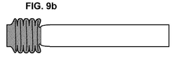
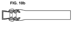
도 7 은 변형 이전의 도 9a 및 변형 이후의 도 9b 에 도시된, 전체 단면에서 기계적 저 강도 영역을 포함하는 종래 기술의 공지된 공통 부재가 변형되는 동안 흡수된 에너지와, 변형 이전의 도 10a 및 변형 이후의 도 10b 에 도시된, 주기적인 프로파일로 하나의 가장자리를 따라서 분포된 기계적인 저 강도 영역을 포함하는 본 발명의 부재가 변형되는 동안 흡수된 에너지를 비교하여 나타낸 곡선들을 도시한다.
도 8 은 변형 이전의 도 9a 및 변형 이후의 도 9b 에 도시된, 전체 단면에서 기계적인 저 강도 영역을 포함하는 종래 기술의 공통 부재 및, 변형 이전의 도 10a 및 변형 이후의 도 10b 에 도시된, 주기적인 프로파일로 하나의 가장자리를 따라서 분포된 기계적인 저 강도 영역을 포함하는 본 발명의 부재 각각에 대하여, 동일한 부재들의 변형 진폭의 함수로서 발생된 힘을 나타내는 비교 곡선을 도시한다.
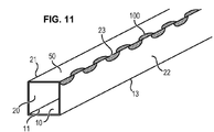
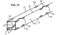
도 11, 도 12 및 도 13 은 본 발명에 따른 부재들의 3 개 실시예들을 도시하는 사시도이다.
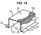
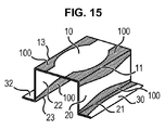
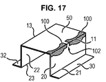
도 14, 도 15, 도 16 및 도 17 은 본 발명에 따른 기계적인 저 강도 밴드 프로파일의 4 가지 변형예들을 도시한다.
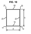
도 18 은 부재 단면을 개략적으로 도시하며 2 개의 대향하는 벽들 사이의 최대 거리에 대응하는 진폭(b)을 나타낸다.
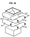
도 19 는 본 발명의 부재의 특정 예를 도시하는 반면에, 도 20 은 동일한 부재로부터 길이 방향 장력으로 얻어진 변형을 도시한다.
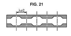
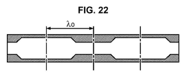
도 21 및 도 22 는 베이스 파동 길이의 각각의 곱에 대응하는 본 발명의 저 강도 밴드들을 비교하여 나타낸다.
도 23 은 본 발명에 따른 부재의 2 개의 인접한 측에 있는, 즉, 상기 2 측 사이에 있는, 기계적인 저 강도 밴드의 분포를 각각 도시한다.
도 24 는 동일한 구획의 확대도를 도시한다.
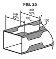
도 25 는 본 발명에 따른 부재의 일 측을 기계적인 저 강도 영역들로 포괄하는 범위를 나타낸다.
도 26 은 본 발명에 따른 대안의 실시예를 도시하는데, 여기에서 일 가장자리를 따라서 파동을 이루어 상기 가장자리를 형성하는 벽들 각각에서 주로 번갈아서 연장되는 기계적인 저 강도 영역은 일련의 기계적인 저 강도의 연속된 간격들에 의해 형성된다.
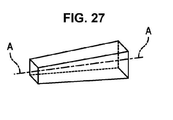
도 27 은 부재의 길이를 따라서 변화되는 단면을 가진 본 발명의 부재의 변형예를 개략적으로 도시하며, 단면은 다른 것들 중에서도 일 단부로부터 다른 단부로 점진적으로 증가한다.
도 28 은 직선이 아닌, 주 연결 축에 중심을 맞춘 본 발명의 부재의 다른 변형예를 개략적으로 도시한다.
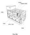
도 29a 및 도 29b 는 레이저 시스템의 각각의 예를 도시한다. Other features, objects, and advantages of the present invention will emerge from the following description, which is an exemplary and non-limiting description only, and is described with reference to the drawings.
BRIEF DESCRIPTION OF THE DRAWINGS Figure 1 IA is a partial perspective view of an example of nine non-limiting geometric shapes of a member that may be utilized in connection with the present invention.
Figs. 2A, 2B and 2C show examples of three alternatives of the cross sections of the members having a geometric shape shown in Fig. 1C.
Figures 3, 4, and 5 show perspective views of metal members in accordance with three embodiments of the present invention.
Figures 6a, 6b, 6c and 6d illustrate four periodic profile variations that define the edges of a mechanical low strength region extending along one edge in accordance with the present invention.
Figure 7 shows the energy absorbed during deformation of a prior art known common member, including the mechanical low strength region, in the entire cross-section, shown in Figure 9a before and after deformation Figure 9a, Figure 10B shows the curves shown in Figure 10B after deformation by comparing the absorbed energy during deformation of a member of the present invention including a mechanical low intensity region distributed along one edge with a periodic profile.
Figure 8 shows a prior art common element including a mechanical low strength region in its entire cross section, shown in Figure 9a prior to deformation and in Figure 9b after deformation, and Figure 10b before deformation and Figure 10b after deformation For each member of the present invention including a mechanical low intensity region distributed along one edge in a periodic profile, the force generated as a function of the deformation amplitude of the same members.
11, 12 and 13 are perspective views showing three embodiments of members according to the present invention.
Figures 14, 15, 16 and 17 illustrate four variations of the mechanical low intensity band profile according to the present invention.
Figure 18 schematically shows a member section and shows the amplitude (b) corresponding to the maximum distance between two opposing walls.
Figure 19 shows a specific example of a member of the present invention, while Figure 20 shows a strain obtained with longitudinal tension from the same member.
Figs. 21 and 22 show a comparison of the low intensity bands of the present invention corresponding to each product of the base wave length.
Figure 23 shows the distribution of the mechanical low intensity bands on two adjacent sides of the member according to the invention, i.e. between the two sides, respectively.
Figure 24 shows an enlarged view of the same compartment.
Figure 25 shows a range covering one side of a member according to the present invention with mechanical low strength regions.
26 shows an alternative embodiment according to the present invention in which the mechanical low intensity areas, which in the form of waves along one edge and extending primarily from each of the walls forming the edge, Lt; / RTI >
Figure 27 schematically shows a variation of the inventive element with a cross section varying along the length of the element, the cross section gradually increasing from one end to the other among others.
Figure 28 schematically illustrates another variation of the inventive element centered on the main connection axis, rather than a straight line.
29A and 29B show respective examples of the laser system.
일반적으로, 본 발명의 부재들은 평탄한 금속 블랭크로부터 만들어진다. In general, the members of the present invention are made from a flat metal blank.
상기 부재들은 주 길이 방향 축 A-A (신장의 주 축 또는 <주 연결 축>에 대응)에 직각으로, 직선의 단면을 얻도록 드로우잉(drawing)되는데, 이것은 선택된 적용에 따른다. 이러한 단면은 다양한 형태들로 구현될 수 있다. The members are drawn to obtain a straight cross section at right angles to the main longitudinal axis A-A (corresponding to the main axis of the extension or < main connection axis >), depending on the application selected. This cross section can be implemented in various forms.
위에서 설명된 바와 같이, 부재들은 전체적으로 고정 수단(fastening means) 및 장착 인터페이스(mounting interfaces)를 포함하며, 예를 들어, 이것은 다른 것들 중에서, 플랜지들 안에 형성된 고정 구멍들의 형상인 것을 포함한다. As described above, the members generally include fastening means and mounting interfaces, for example, among other things, the shape of the fixing holes formed in the flanges.
다른 한편으로, 본 발명의 부재들은 적어도 하나의 기계적인 저 강도 영역을 가지는데, 상기 영역에서는 인장 강도가 1000 MPa 미만으로서, 이는 적어도 1300 MPa의 기계적 강도, 바람직스럽게는 1400 MPa 보다 큰 기계적 강도를 가지는 부재의 나머지에 비교된 것이며, 기계적인 저 강도 영역은 길이 방향 가장자리를 따라서 파동을 이루는 패턴에 의해 한정되고, 상기 가장자리를 형성하는 2 개의 벽들 각각에서 주로 번갈아서 연장된다. On the other hand, the members of the present invention have at least one mechanical low strength region in which the tensile strength is less than 1000 MPa, which has a mechanical strength of at least 1300 MPa, preferably greater than 1400 MPa Is compared to the remainder of the member and the mechanical low strength region is defined by the undulating pattern along the longitudinal edge and extends primarily alternately at each of the two walls forming the edge.
본 발명의 다른 유리한 특징에 따르면, 부재들은 적어도 하나의 기계적인 저 강도 영역을 가지는데, 상기 영역의 항복 한계(yield limit)는 950 MPa 미만이며, 이는 적어도 1000 MPa 의 항복 한계, 바람직스럽게는 1150 MPa 를 초과하는 항복 한계를 가진 부재의 나머지에 비교된 것이며, 기계적 저 강도 영역은 길이 방향 가장자리를 따라서 파동을 이루는 패턴에 의해 한정되고, 상기 가장자리를 형성하는 2 개의 벽들 각각에서 주로 번갈아서 연장된다. According to another advantageous feature of the invention, the members have at least one mechanical low strength zone, the yield limit of which is less than 950 MPa, which is at least 1000 MPa, preferably 1150 MPa and the mechanical low strength region is defined by a pattern of undulations along the longitudinal edge and extends primarily alternately at each of the two walls forming the edge.
본원에 첨부된 도면에 도시된 본 발명의 부재들이 바람직스럽게는 길이를 따라서 일정한 단면을 가지며, 이것은 예를 들어 도 1 및 도 2 에 도시된 것에 대응한다. 그러나, 대안의 실시예에 따르면, 부재들의 단면은 도 27 에 도시된 바와 같이 부재들의 길이를 따라서 변화될 수 있다. The elements of the present invention shown in the drawings attached hereto preferably have a constant cross-section along their length, which corresponds, for example, to that shown in Figs. 1 and 2. However, according to an alternative embodiment, the cross-section of the members may vary along the length of the members as shown in Fig.
다른 한편으로, 본 발명의 부재들은 주 길이 방향 축 AA 또는 주 연결 축에 중심이 맞춰질 수 있으며, 상기 축은 직선이거나 또는 도 28 에 도시된 바와 같이 직선이 아닐 수 있다. On the other hand, the members of the present invention may be centered on the main longitudinal axis AA or the main connection axis, and the axis may be straight or not straight as shown in FIG.
본 발명에 따른 전체적으로 모자(hat) 형상 부재의 일 예는 첨부된 도 1a 에 도시되어 있으며, 이것은 부재의 저부를 형성하는 코어(10)와 상기 코어(10)에 전체적으로 직각이고 벽을 형성하는 2 개의 벽(20,22)을 가지는 U 형상 동체(12)를 포함한다. 측부 플랜지(30,32)들은 벽(20,22)들에 전체적으로 직각으로 연장되고 따라서 부재(10)의 저부에 전체적으로 외측으로 평행하다. 저부(10)는 개별의 가장자리(11,13)들에 의해 벽(20,22)들에 연결된다. 벽(20,22)은 개별의 가장자리(21,23)들을 통하여 플랜지(30,32)들에 연결된다. 본 발명과 관련하여, 적어도 하나의 기계적인 저 강도 영역은 도 1a에 도시된 부재에서 가장자리(11,13,21 또는 23)들중 적어도 하나를 따라서 파동을 이루어 형성되어, 상기 가장자리를 형성하는 벽들 각각에서 주로 번갈아서 연장된다. An example of a generally hat-shaped member according to the present invention is shown in the accompanying FIG. 1A, which shows a core 10 forming the bottom of the member and a
도 1b 에 도시된 변형예는 덮개 플레이트(40)의 제공에 의해서만 도 1a 와 차이나며, 덮개 플레이트는 플랜지(30,32)들에 의해 지지되고 플랜지에 부착됨으로써 U 형상 동체(12)의 개구를 덮는다. 1B differs from that of Fig. 1A only by the provision of the
본 발명에 따른 한가지 변형예는 도 1c 에 도시되어 있으며, 여기에서 부재는 튜브형 부재로서, 이러한 예에 제한되지 않으면서, 4 개의 전체적으로 평탄한 벽(10,20,22,50)들에 의해 정해진 직선의 단면을 포함하는데, 벽들은 각각 쌍을 이루어 직각이고 평행하며 가장자리(11,13,21,23)들에 의해 쌍을 이루어 함께 연결된다. 다시, 본 발명과 관련하여, 적어도 하나의 기계적인 저 강도 영역은 도 1c 에 도시된 부재에 형성되는데, 가장자리(11,13,21,또는 23)들중 적어도 하나를 따라서 파동을 이루고 상기 가장자리를 형성하는 벽들 각각에서 주로 번갈아서 연장된다. 도 1c 에 대응하는 도 2a 는 4 개의 벽(10,20,22,50) 및 따라서 4 개의 가장자리(11,13,21 또는 23)를 가지는 정사각형 단면을 도시한다. 도 2b 는 6 개의 벽(10,20,22,50,52,54)을 포함하고 6 개의 가장자리(11,13,21,25,27)들에 의해 쌍으로 연결된 6 각 섹션 유형의 튜브형 부재의 변형예를 도시하고, 도 2c 는 8 개의 벽(10,20,22,50,54,56,58)들이 8 개의 가장자리(11,13,21,23,24,25,26,27)들에 의해 쌍으로 연결된 8 각형 튜브형 부재의 다른 변형예를 도시한다. One variant according to the invention is shown in figure 1c, in which the member is a tubular member, without limitation to this example, a straight line defined by four generally flat walls (10, 20, 22, 50) The walls being each pair orthogonal and parallel and connected together by pairs of
대안의 실시예는 도 1d 에 도시되어 있으며, 상기 실시예에 따라서 본 발명의 부재는 도 1a 에 도시된 유형의 2 개의 블랭크들을 조립함으로써 형성되는데, 부재는 그들의 플랜지들이 서로를 향하고 플랜지들에 의해 쌍을 이루어 상호 접촉되어 부착된다. 도 1d 에 도시된 바와 같이, 2 개 블랭크들의 요소들은 도 1a 에 도시된 것과 같은 참조 번호를 가지지만, 참조 번호는 a 또는 b 첨자에 의하여 각각 관련된다. An alternative embodiment is shown in Figure 1d, and according to this embodiment a member of the present invention is formed by assembling two blanks of the type shown in Figure < RTI ID = 0.0 > 1A, And are attached to each other in pairs. As shown in Fig. 1d, the elements of the two blanks have the same reference numerals as shown in Fig. 1A, but the reference numerals are respectively related by a or b subscripts.
대안의 실시예는 도 1e 에 도시되어 있으며, 상기 실시예에 따라서 본 발명의 부재는 2 개의 블랭크(L)를 조립함으로써 형성되는데, 이것은 2 개의 상호 직각인 벽(10a,20a 및10b,20b)을 각각 포함하고, 벽(20a,20b)들중 하나는 플랜지(30a,30b)를 통하여 다른 벽(10a,10b)에 평행하게 외측으로 연장되고 부재의 상기 다른 벽(10a,10b)에 의해 지지되고 그에 부착된다. 벽(10a,20a, 및 10b, 20b)은 각각 하나의 가장자리(11a,11b)에 의해 함께 연결되고, 플랜지(30a,30b)들은 가장자리(21a,21b)에 의해 벽(20a,20b)에 연결된다. 다시, 본 발명과 관련하여, 적어도 하나의 기계적인 저 강도 영역이 도 1e 에 도시된 부재에서 가장자리(11a,11b,21a,21b)들중 적어도 하나를 따라서 파동을 이루게 형성되어 상기 형상화된 가장자리를 형성하는 벽들 각각에서 주로 번갈아서 연장된다. An alternative embodiment is shown in FIG. 1e, and according to this embodiment, a member of the present invention is formed by assembling two blank Ls, which are two mutually
도 1f 에 도시된 변형예는 벽(10a,10b)의 동체들과 그것의 단부 사이의 변위부 또는 이동부(31a,31b)의 존재에 의하여 도 1e 와 상이한데, 상기 변위부 또는 이동부가 플랜지(30b,30a)상에 놓이기 때문이며, 여기에서 단부는 제 2 플랜지(32a,32b)를 구성한다. 마찬가지로, 하나의 가장자리(13a, 13b)는 벽 동체(10a,10b)와 변위부 또는 이동부(31a,31b) 사이에 형성되고, 다른 가장자리(23a, 23b)는 변위부 또는 이동부(31a, 31b)와 관련 플랜지(32a, 32b) 사이에 형성된다. 다시 본 발명과 관련하여, 적어도 하나의 기계적인 저 강도 영역은 도 1f 에 도시된 부재에서 가장자리(11a, 11b, 21a, 21b, 또는 13a, 13b, 23a, 23b)들중 적어도 하나를 따라서 파동을 이루어 형성되어 상기 가장자리를 형성하는 벽들 각각에서 주로 교번하여 연장된다. 1F is different from FIG. 1E due to the presence of displacements or moving
도 1g 에 도시된 일 실시예에 따르면, 부재는 U 형상 동체(12)를 포함하고, 상기 U 형상 동체는 부재의 저부를 형성하는 코어(10) 및 상기 코어(10)에 실질적으로 직각이고 벽들을 형성하는 2 개의 벽(20,22)을 포함한다. 부재(10)의 저부는 개별의 가장자리(11,13)들에 의하여 벽(20,22)들에 연결된다. 본 발명과 관련하여, 적어도 하나의 기계적인 저 강도 영역은 도 1g 에 도시된 부재에서 가장자리(11 또는 13)들중 적어도 하나를 따라서 파동을 이루어 형성되어 상기 가장자리를 형성하는 벽들 각각에서 주로 교번되게 연장된다. According to one embodiment shown in FIG. 1G, the member includes a
도 1h 에 도시된 변형예는 U 형상 동체(12)의 개구를 덮는 덮개 플레이트(60)의 존재에 의하여 도 1g 와 상이하다. 도 1h 에 따르면 덮개 플레이트(60)는 오목함이 부재 외측으로 향하는 U 자 형태 기하 형상을 가진다. 이것은 자유 단부들에 인접한 벽(20,22)들의 내측면상에서 측벽들에 의해 고정된다. 덮개 플레이트(60)와 벽(20,22)들 사이의 연결 영역(61,62)들은 가장자리들과 유사하다. 적어도 하나의 기계적인 저 강도 영역은 도 1h 에 도시된 부재에서 가장자리(11 또는 13 또는 61, 62)들중 적어도 하나를 따라서 파동을 이루어 형성되어 상기 가장자리를 형성하는 벽들 각각에서 주로 교번하여 연장된다. The modification shown in Fig. 1 (h) differs from Fig. 1 (g) by the presence of the
변위부 또는 이동부(31a,31b)들이 단순한 가장자리(13a,13b)에 의해 대체되고 그에 의하여 플랜지(30a,32b,30b,32a)들이 한정되고, 플랜지가 도 1e 및 도 1f 에서와 같이 부재(10a,10b)들의 저부에 평행하게 연장되지 않지만, 가장자리(13a,13b)를 통하는 부재들의 대각선을 통과하는 평면에 따라서 연장된다는 점에서, 도 1i 에 도시된 실시예는 도 1f 에 도시된 실시예와 상이하다. The
도 3 및 도 4 는 본 발명에 따른 금속 부재(P)의 2 개 예를 도시하며, 길이 방향 축 또는 <주 연결 축> A을 따라서 전체적으로 연장되고, 4 개의 전체적으로 평탄한 벽(10,20,22,50)들에 의해 정의된 튜브형 단면을 포함하고, 상기 벽들은 쌍을 이루어 각각 평행하고 직각이다. 교선(intersection)에서 하나의 가장자리(11,13,21,23)를 형성하는 인접한 벽(10,20,22,50)들 각각의 쌍은 도 1c 와 관련하여 위에서 주목된 바와 같이 길이 방향 축(A)에 전체적으로 평행하게 연장된다. 3 and 4 show two examples of the metallic member P according to the present invention, which extend entirely along the longitudinal axis or main connection axis A and comprise four generally
도 3 및 도 4 에 도시된 금속 부재(P)들 각각은 동체의 나머지보다 낮은 기계적 강도를 가지는 적어도 하나의 영역(100)을 포함한다. 보다 상세하게는, 도 3 및 도 4 에 도시된 실시예들에 따라서, 4 개의 기계적인 저 강도 영역(100)들이 형성되는데, 가장자리(11,13,21 또는 23)들 각각을 따라서 각각 파동을 이루어서 상기 가장자리(11,13,21 또는 23)들을 형성하는 벽(10,20,22,50)들 각각에서 주로 번갈아서 연장된다. Each of the metal members P shown in Figs. 3 and 4 includes at least one
기계적인 저 저항(low resistance) 영역(100)은 예를 들어 부재(P)의 드로우잉 동안에 국부적인 열 제어에 의하여 형성되거나, 또는 다른 등가의 기술에 의하여 형성되며, 예를 들어 레이저 비임 또는 인덕션(induction)에 의하여 부재를 국부적으로 열 제어함으로써 형성된다. The mechanical
기계적인 저 저항 영역(100)은 마이크로 구조를 변화시키도록, 예를 들어 전성(ductility)을 증가시키도록 선택될 수 있다. 기계적인 저 저항 영역(100)의 선택은 충돌 시험 또는 시뮬레이션 시험에 기초할 수 있으며, 비록 기계적인 저 저항 영역을 선택하는 일부 다른 방법들이 가능할지라도 그러하다. 예를 들어 레일과 같은 단순한 부분에서의 보다 우수한 에너지 흡수 또는 가장 유리한 충돌 거동을 판단하기 위하여, 기계적인 저 저항 영역(100)이 시뮬레이션에 의해 정해질 수 있다. 레이저 비임(미도시)은 선택된, 기계적인 저 저항 영역(100)으로 레이저 시스템을 이용하여 가해질 수 있다. 일부 예에서, 레이저 스폿 크기(laser spot size)는 레이저 비임의 적용 동안에 조절될 수 있고 기계적인 저 저항 영역(100)들의 높이 및/또는 폭에 적합화될 수 있어서, 레이저의 각각의 적용 이후에 레이저 시스템의 옵틱(optic)의 시간 소비적인 변화는 회피될 수 있다. The mechanical
이러한 방식으로, 기계적인 저 저항 영역(100)의 형상은 레이저 스폿 크기를 조절하면서 레이저 시스템의 오직 하나의 옵틱만으로 얻어질 수 있다. 결국, 유지 관리 비용 뿐만 아니라 툴(tool)에 대한 투자도 감소될 수 있다. 제조 시간도 짧아질 수 있다. 더욱이, 스폿의 변화는 기계적인 저 저항 영역(100)의 시작 및 최종 지점에서 천이 영역(transition zones)을 감소시킬 수 있다. In this way, the shape of the mechanical
레이저 비임은 일부 파라미터에 기초하여 조절될 수 있으며, 예를 들어, 고온을 측정하는 파이로미터(pyrometer) 또는 카메라와 같은 온도계를 이용하여 기계적인 저 저항 영역(100)에서 측정된 온도에 기초하여 조절될 수 있어서, 레이저 비임 스폿의 온도를 유지한다. 기계적인 저 저항 영역들은 상이한 형상을 가지고 상이한 적용예를 가지면서 만들어질 수 있으며, 예를 들어 플랜지, 작거나 또는 커다란 지점(spot), 복합적인 기하 형상을 가지도록 만들어진다. The laser beam may be adjusted based on some parameters and may be adjusted based on the temperature measured in the mechanical
본 발명과 관련하여, 기계적인 저 강도 영역(100)을 형성하도록 부재 영역의 기계적 강도를 국부적으로 감소시키는 처리, 소망되는 기계적인 저 강도 영역(100)을 제외하고 부재 동체의 기계적인 강도를 국부적으로 증가시키는 처리, 또는 이들 2 가지 유형의 조합으로 처리가 이루어질 수 있다. In the context of the present invention, the process of locally reducing the mechanical strength of the member area to form the mechanical
따라서 금속 부재(P)들은 적어도 하나의 기계적인 저 강도 영역(100) 및, 동체의 나머지에 대응하는 적어도 하나의 기계적인 고 강도 영역(150)을 포함한다. Thus, the metal members P include at least one mechanical
기계적인 저 강도 영역(100)은 1100MPa 보다 작은 기계적인 저 강도(인장 강도)를 가지고, 통상적으로 500 내지 1000MPa 범위의 강도를 가지는 반면에, 기계적인 고 강도 영역(150)은 1100 MPa 보다 높은 기계적 강도(인장 강도)를 가지며, 바람직스럽게는 적어도 1300 MPa 와 같은 기계적 강도 및 통상적으로 1400 MPa 를 넘는 기계적 강도를 가진다. The mechanical
기계적 저 강도 영역(100)은 예를 들어 부재(P)의 드로우잉 온도(drawing temperature)를 국부적으로 제어함으로써 형성된다. 부재(P)는 오스테나이트 상(austenite phase)을 얻기에 적절한 온도 범위로 가열되고, 다음에 드로우잉된 부재의 상이한 영역들에서 상이한 온도를 한정하도록 적합화된 스탬핑 공구(stamping tool)에서 드로우잉되는데, 예를 들어 스탬핑 공구에 형성된 국부적인 요부들을 통하여 또는 스탬핑 공구의 국부적인 과열에 의하여 드로우잉된다. The mechanical
도 3 및 도 4 에 도시된 실시예들에 따르면, 기계적인 저 강도 영역(100)들은 가장자리를 따라서 전체적으로 주기적인 패턴을 형성하기 위하여, 하나의 가장자리(11,13,21 또는 23)를 따라서 벽(10,20,22,50)들 각각에서 번갈아서 연장된다. According to the embodiments shown in Figures 3 and 4, the mechanical
보다 상세하게는, 도 3 및 도 4 에 도시된 실시예들에 따라서, 영역(100)들은 주기적으로 구불구불한 사인 곡선(sinusoidal) 구성이다. 따라서, 이들은 한편으로 개별의 가장자리(11,13,21 또는 23)에 대응하는 직선 가장자리에 의해 한정되고 다른 한편으로 가장자리(11,13,21 또는 23)들의 양측에서 사인 곡선의 파동에 의하여 한정된다. More specifically, according to the embodiments shown in Figures 3 and 4, the
그러나, 본 발명은 이러한 구성에 제한되지 않는다. 다른 유형의 주기적인 프로파일로 연장될 수 있다. 본 발명의 주기적인 프로파일의 4 가지 변형은 예를 들어 도 6a, 도 6b, 도 6c 및 도 6d 에 각각 도시되어 있으며, 이것은 각각 사인 곡선, 정사각형, 삼각형 또는 톱니 형상을 가진다. However, the present invention is not limited to this configuration. Can be extended to other types of periodic profiles. Four variations of the periodic profile of the present invention are shown, for example, in Figs. 6A, 6B, 6C and 6D, respectively, which have a sinusoidal, square, triangular or serrate shape.
도 3 및 도 4 에 도시된 예에서, 기계적인 저 강도 영역(100)들의 패턴은 가장자리(11, 13,21 또는 23)를 따라서 연속적으로 연장되게 배치된다. 도 13 의 개략적인 실시예에 따르면, 패턴들은 가장자리(11,13,21 또는 23)를 따라서 불연속적으로 연장된다. 따라서, 도 13 에 도시된 특정 실시예에 따르면, 기계적인 저 강도 영역(100)의 각각의 밴드(band)는 파동의 프로파일(wave profile)과 사인 곡선 프로파일의 절반을 덮고, 연속적인 영역(100)의 2 개 밴드들은 절반의 파동 길이에 의해 분리된다. In the example shown in FIGS. 3 and 4, the pattern of mechanical
도 3 및 도 4 에 도시된 예에서, 가장자리(11,13,21 또는 23) 아래에서 형성된 기계적인 저 강도 영역(100)의 모든 패턴들은 같은 주기(T)를 가진다. 3 and 4, all the patterns of the mechanical
변형예(미도시)에 따르면, 가장자리(11,13,21또는 23) 아래에서의 기계적인 저 강도 영역(100)의 패턴들은 상이한 주기(T)일 수 있다. According to a variant (not shown), the patterns of the mechanical
패턴들의 절반의 주기(T/2)인 λ/2는 바람직스럽게는 0.2 x b 내지 1 x b 의 범위이고, 통상적으로 0.8 x b 와 같으며, 여기에서 b 는 도 18 에 도시된 부재(P)에서 대향하는 벽(10,50) 사이의 최대 거리에 대응한다. 도 18 은 사각형 단면을 가진 튜브형 부재에 해당한다. 4 보다 큰 다수의 측부들을 가진 튜브형 부재에 대하여, 거리(b)는 벽과 적어도 실질적으로 반대편 벽 사이의 최대 거리에 대응한다. 이러한 0.8 x d 의 최적화는 부재(P)를 따른 변형 영역들의 초기 형상에 대한 규칙적인 위치가 최적화될 수 있게 한다. 실제로, 이러한 경우에, 변형 영역들의 위치는 자연 변형 단계에 따라서 부재를 따라 분포된다. Lambda / 2, which is the period (T / 2) of the patterns, is preferably in the range of 0.2 xb to 1 xb, and is usually equal to 0.8 xb, where b is the length of the opposite (P) 50 < / RTI > Fig. 18 corresponds to a tubular member having a rectangular cross section. For a tubular member having a plurality of sides greater than 4, the distance b corresponds to the maximum distance between the wall and the wall at least substantially opposite. This optimization of 0.8 x d makes it possible to optimize the regular position of the initial shape of the deformation areas along the member P. In practice, in this case, the positions of the deformation areas are distributed along the member in accordance with the natural deformation step.
그러나, 변형예에 따르면, 만약 상기 언급된 특정의 적용예에 따라서, 자연 변형 단계와 상이한 단계에 따라 부재의 변형을 강제시킬 것이 소망된다면, 패턴들의 주기(T/2)가 달라질 수 있다.However, according to a variant, according to the specific application mentioned above, the period of the patterns (T / 2) can be varied if it is desired to force deformation of the member according to steps different from the natural deformation step.
도 12 에 도시된 실시예에 따라서, 기계적인 저 강도 영역(100)에 대한 패턴들은 가변적인 파동 길이를 가진다. According to the embodiment shown in Figure 12, the patterns for the mechanical
도 3 및 도 4 에 도시된 예에서, 하나의 벽(10,20,22 또는 50)에 연장된 패턴들은 반대의 위상을 이룬다. 예를 들어 벽(50)에 배치된 가장자리(21)와 비교된 폴라리티(polarity) 및 가장자리(21)에 제공된 영역(100)들의 내부(interior)는, 같은 벽(50)에 마찬가지로 배치된 가장자리(23)에 제공된 프로파일의 내부와 각각 마주한다는 점이 이해된다. In the example shown in FIGS. 3 and 4, the patterns extending in one
<내부>는 기계적인 저 강도 프로파일의 일부를 의미하고, 관련된 가장자리로부터 가장 분리되어 있음 및/또는 상기 기계적인 저 강도 프로파일이 가장 넓은 레벨을 의미한다. ≪ inner > means a portion of the mechanical low intensity profile, which is the most separated from the associated edge and / or the mechanical low intensity profile means the widest level.
도 3 에 도시된 부재(P)는 추가의, 기계적인 저 강도 부분(110)들을 더 포함하는데, 이것은 동일한 벽(10,20,22,50)에서 서로 마주하면서 연장되는 상이한 패턴들의 내부의 부분들 사이에서 각각의 벽(10,20,22,50)에 연장된다. 추가의, 기계적인 저 강도 영역(110)들은 예를 들어 전체적으로 디스크 형상이다. The member P shown in Fig. 3 further comprises additional, mechanical, low-
변형예(미도시)에 따르면, 추가의, 기계적인 저 강도 영역(110)들은 내부의 부분들에 대하여 길이 방향으로 이동하여 동일한 벽(10,20,22,50)에서 서로를 마주하면서 연장된다. According to a variant (not shown), the additional, mechanical,
도 3 에 도시된 예에서, 동일한 벽(10,20,22,50)의 보충의 기계적인 저 강도 영역(110)들은 전체적으로 길이 방향 축(A)에 평행하게 정렬되고, 내부의 부분들로부터 전체적으로 절반으로 연장되어 동일한 벽에서 서로를 마주하면서 연장된다. 3, the complementary mechanical
도 4 에 도시된 예에서, 동일한 벽(10,20,22,50)에서 연장되는 패턴들은 반대의 위상을 이룬다(oppoiste in phase). 부재(P)는 다른 추가의, 기계적인 저 강도 영역(110)을 포함하며, 이것은 각각의 벽(10,20,22,50)에서 횡방향으로 연장됨으로써 상이한 패턴들의 내부의 부분들이 서로 연결되어, 동일한 벽(10,20,22,50)에서, 그러나 대향하는 가장자리(11,13,21 또는 23)들에서 서로를 향하여 연장된다. In the example shown in Fig. 4, the patterns extending from the
도 5 에 도시된 실시예는 도 1b 에 도시된 부재에 기초한 것이다 (모자 형상 부재 및 덮개 플레이트 조립체). 도 5 에 도시된 예에서, 기계적인 저 강도 영역(100)들의 패턴들은 동일한 벽(10,20,22,50)에서 연장되지만, 대향하는 가장자리(11,13,21 또는 23)에서 동일한 위상을 이룬다. 예를 들어 가장자리(21)에 제공된 프로파일의 내부들 및 벽(50)에 배치된 가장자리(21)와 비교된 극성(polarity)은, 동일한 벽(50)에 동일한 방식으로 배치된 대향하는 가장자리(23)에 제공된 프로파일의 내부들에 대하여 각각 반대 위상을 이룬다. 도 5 에 도시된 실시예에 따르면, 가장자리를 따라서 파동을 이루는 기계적인 저 강도 영역(100)들에서 그 어떤 추가적인 영역(150)도 제공되지 않는다. 기계적인 저 강도 영역(100)은 가장자리(11,13,21,23)들 각각에서 연장된다. The embodiment shown in Fig. 5 is based on the member shown in Fig. 1B (hat-shaped member and cover plate assembly). 5, the patterns of the mechanical low-
본 발명은 강철로 만들어진 부재에 관한 것이다. The present invention relates to a member made of steel.
이것은 차량에 포함된 그 어떤 유형의 부재들에 적용될 수 있으며, 예를 들어, 다른 것들중에서 B-필라 또는 측부 비임, 또는 댐핑 또는 에너지 흡수 장치를 포함하는 것에 적용된다. This applies to any type of member included in the vehicle, for example, among others, B-pillar or side beam, or damping or energy absorbing device.
변형 천이 영역들이 압축시의 축방향 힘을 가하는 동안 기계적인 저 강도 영역(100)들에 의해 형성되어 신장된 부재(P)의 측방향 변형의 방향을 지향시킬 수 있어서, 부재들의 임의적인 변형을 방지한다. The deformation transition regions can be formed by the mechanical
본 발명은 예를 들어 캐빈(cabin)의 측부 비임 변형이 외측을 향하게 하고 내측을 향하게 하지 않음으로써, 캐빈 점유자의 충격 위험성을 최소화시킨다. The present invention minimizes the risk of impact of the cabin occupant, for example by not allowing the side beam deformation of the cabin to be directed outward and inward.
본 발명은 사고시에 주로 에너지의 흡수를 최적화시킬 수 있다. The present invention can mainly optimize the absorption of energy at the time of an accident.
도 7 에 도시된 곡선들을 비교하면, 본 발명에 따른 부재의 변형중에 흡수된 에너지(곡선 A)는 당해 기술 분야에서 공지된 공통적인 부재의 변형중에 흡수된 에너지(곡선 B)보다 크다. 위에서 지적된 바와 같이, 곡선 B 는 변형 이전의 도 9a 및 변형 이후의 도 9b 에 도시된 바와 같이 전체 단면에서 기계적인 저 강도 영역을 포함하는, 당해 분야에서 공지된 공통적인 부재의 변형중에 흡수된 에너지를 나타내는 반면에, 곡선 A 는 변형 이전의 도 10a 및 변형 이후의 도 10b 에 도시된 바와 같이, 하나의 가장자리를 따라서 파동을 이루는 기계적인 저 강도 영역을 포함하는 본 발명의 부재의 변형중에 흡수된 에너지를 나타낸다. 7, the absorbed energy (curve A) during deformation of the member according to the present invention (curve A) is greater than the absorbed energy (curve B) during deformation of a common member known in the art. As pointed out above, the curve B is absorbed during the deformation of a common member known in the art, including the mechanical low strength region in its entire cross section, as shown in Figure 9a before deformation and Figure 9b after deformation While curve A shows the energy absorbed during deformation of the member of the present invention including a mechanical low intensity region that oscillates along one edge, as shown in Figure 10a before deformation and Figure 10b after deformation. Energy.
보다 상세하게는, 도 7 에 도시된 예에 따라서, 본 발명의 부재에 의하여 흡수된 에너지는 종래 기술에 따른 부재에 의해 흡수된 에너지의 65 % 정도로 더 크다. More specifically, according to the example shown in Fig. 7, the energy absorbed by the member of the present invention is as large as 65% of the energy absorbed by the member according to the prior art.
본 발명은 또한 사고의 경우에 차량 점유자가 겪는 가속 정점(acceleration peaks)이 감소될 수 있게 한다. The present invention also allows acceleration peaks experienced by a vehicle occupant to be reduced in case of an accident.
위에서 지적된 바와 같이, 도 8 은 동일한 부재들의 변형 진폭의 함수로서 발생되는 응력을 비교하여 나타내는 곡선들을 도시하며, 변형 이전의 도 9a 및 변형 이후의 도 9b 에 도시된 바와 같이 전체 단면에서 기계적인 저 강도 영역을 포함하는 당해 기술 분야의 공지된 공통적인 부재로부터 초래되는 응력의 곡선 B 를 도시하고, 또한 변형 이전의 도 10a 및 변형 이후의 도 10b 에 도시된, 하나의 가장자리를 따라서 파동을 이루는 기계적인 저 강도 영역을 포함하는 본 발명의 부재로부터 초래된 응력을 도시하는 곡선 A 를 나타낸다. As pointed out above, Figure 8 shows curves representing and comparing the stresses generated as a function of the deformation amplitudes of the same members, showing the mechanical and mechanical properties of the overall cross section, as shown in Figure 9a before deformation and Figure 9b after deformation. Figure 10 shows a curve B of stresses resulting from a known member of the art including a low intensity region and also shows a curve B of stress along the one edge as shown in Figure 10a prior to deformation and Figure 10b after deformation. ≪ / RTI > shows a curve A showing the stresses resulting from a member of the present invention including a mechanical low strength region.
본 발명은 물론 상기 설명된 실시예들에 제한되지 않으며, 발명의 사상내에 속하는 그 어떤 변형에라도 연장된다. The invention is, of course, not limited to the embodiments described above, but extends to any modifications that fall within the spirit of the invention.
부재(P)의 일부 벽에 위치된 조립된 강화부 및/또는 강화 리브(reinforcement rib)의 추가가 이루어질 수 있다. The addition of an assembled reinforcement and / or a reinforcement rib located in a part of the wall of the member P can be made.
본 발명과 관련하여 <금속 부재>라는 용어는, 조립에 의해 이루어지지 않는 단일 블록 구조체(monobloc structure) 및, 초기에 개별화되었지만 조립에 의해 연결된 복수개의 존재들을 조립함으로써 형성된 구조체 모두를 포함하는 넓은 의미로 이해되어야 한다. The term " metal member " in the context of the present invention is intended to encompass both a monobloc structure that is not made by assembly and a broader meaning including both structures initially formed by assembling a plurality of entities, .
본 발명의 대안의 실시예는 도 11 에 도시되어 있으며, 이것은 단일의 가장자리(23)를 따라서 파동을 이루는 기계적인 저 강도를 가지는, 파동을 이루거나 또는 주기적인 프로파일 영역이 제공된 것을 특징으로 한다. An alternative embodiment of the present invention is shown in Fig. 11, which is characterized in that a wavy or periodic profile area is provided, which has a mechanical low strength which oscillates along a
도 14 는 도 1a 에 도시된 모자 형상 부재의 단일 가장자리(11)에서 파동을 이루는 기계적인 저 강도 영역(100)의 일 실시예를 도시한다. 영역(100)의 2 개 경계 가장자리들은 전체적으로 사인 곡선 프로파일이고, 예외적으로 가장자리(11)에 평행한 방향들에 의하여 국부적인 동일 수준이 이루어진다. Figure 14 illustrates one embodiment of a mechanical
도 15 는 도 1a 에 도시된 하나의 부재의 4 개 가장자리(11,13,21,23)들 각각에서 파동을 이루는 기계적인 저 강도 영역(100)을 포함하는 다른 실시예를 도시한다. Figure 15 shows another embodiment comprising a mechanical
도 16 은 도 1b 에 도시된 부재에 적합화된 도 14 의 변형예를 도시하며, 이것에 따라서 기계적인 저 강도 영역(100)은 불연속적이다. 도 16 에 도시된 예에 따라서, 본 발명의 금속 부재는 가장자리(11)의 길이를 따라서 분포되고 양쪽 측부들에서 파동을 이루는 기계적인 저 강도 밴드(100)들의 연속을 포함하는데, 2 개의 연속된 기계적인 저 강도 밴드(100)들은 중간의 기계적인 고 강도 영역(102)에 의하여 분리된다. 보다 상세하게는, 도 16 에 도시된 예에 따라서, 중간의 영역(102)은 가장자리(11)의 양쪽 측부들에서 2 개의 벽(20,50) 사이에 각각 위치된 기계적인 저 강도 영역(100)의 2 개의 내부 부분들 사이에 위치된다. Fig. 16 shows a modification of Fig. 14 adapted to the member shown in Fig. 1B, whereby the mechanical
도 17 은 도 1a 에 도시된 모자 형상 부재에 적용된 도 16 의 변형예를 도시하며, 2 개의 연속된 기계적인 저 강도 밴드(100)들 사이에 위치된 중간의 기계적인 고 강도 영역(102)은 기계적인 저 강도 프로파일의 내부들과 같은 수준에 위치된다. Fig. 17 shows a modification of Fig. 16 as applied to the hat-shaped member shown in Fig. 1A, wherein the intermediate mechanical
도 19 는 사인 곡선 프로파일에 따라서 각각의 가장자리(11,13,21,23)를 따라 파동을 이루는 기계적인 저 강도 영역(100)들을 포함하는 튜브형 부재(P)를 도시하고 사인 곡선 프로파일의 주기는 0.8 x b 인 반면에, 도 20 은 길이 방향 장력에서 동일한 부재로부터 얻어진 변형을 나타낸다. 가장자리를 따라서 파동을 이루는 영역(100)의 존재가 부재의 측부들 각각에서 접힘(fold)이 번갈아서 배치될 수 있게 할 때 당업자들은 도 19 및 도 20 에서의 비교가 이해될 것이다. 실제로, 도 20 에서 도시된 바와 같이, 이러한 배치에 의하여, 부재 외측으로 돌출하는 접힘은 교번되어 대향되는 벽들의 쌍에서 번갈아서 위치된다. 보다 상세하게는, 도 20 에서, 외부의 접힘(190, 192)은 벽(10)에 배치되는 반면에, 외부의 접힘(191,193)은 인접한 벽(22)에 번갈아서 위치된다. Fig. 19 shows a tubular member P comprising mechanical
가장자리를 따라서 파동을 이루는 기계적인 저 강도 영역(100)들을 포함하는 이러한 유형의 부재에서 수행된 시험들에 따르면, 길이를 따라서 분포된, 전체 단면에서 기계적인 저 강도 링들을 포함하는 종래 기술의 부재들과 비교하여, 본 발명은 충돌의 경우에 응력 정점(stress peak)이 종래 기술과 같은 수준에서 제한될 수 있게 하고, 변형중에 부재의 파열 위험성 없이 흡수된 에너지가 65 % 정도로 증가되게 한다. According to tests carried out on members of this type, including mechanical
도 21 및 도 22 는 본 발명에 따른 기계적인 저 강도 밴드들을 비교하여 도시하며, 밴드들의 주기는 개별적인 다수의 베이스 파동 길이 λO 에 대응한다. 보다 상세하게는, 도 22 에 도시된 기계적인 저 강도 영역(100)들의 길이는 도 21 에 도시된 기계적인 저 강도 영역(100)의 주기의 2 배이다. 통상적으로, 그러나 도 21 에 도시된 영역(100)들의 주기에 제한되지 않은 것으로, 부재의 자연 변형의 주기(λO)와 같을 수 있고, 부재의 변형의 자연 주기의 절반(λO/2)에 같을 수 있는 반면에, 도 22 에 도시된 영역(100)들의 주기는 도 21 의 주기의 2 배이다. Figures 21 and 22 illustrate mechanical low strength bands in accordance with the present invention in comparison, with the period of the bands corresponding to a plurality of individual base wave lengths [lambda] 0 . More specifically, the length of the mechanical
도 23 및 도 24 에 도시된 바와 같이, 본 발명의 다른 유리한 특징에 따르면, 하나의 가장자리를 따라서 파동을 이루는 기계적인 저 저항 영역(100)은 상기 가장자리를 형성하는 벽들 각각에서 주로 번갈아서 연장되고 공통의 가장자리의 양쪽 측부상의 2 개 벽들에서 부분적으로 연장되는데, 패턴들 내부의 수준에서의 신장의 주 축(A)에 횡방향인 섹션에 따른 선형 분포는, 저 강도 패턴의 절반의 주기의 수준에 대하여 가장자리에 인접한 제 1 벽에서 적어도 60 %, 바람직스럽게는 적어도 70% 이고, 가장자리에 인접한 제 2 벽에서 최대 40 %, 바람직스럽게는 적어도 30% 이도록, 번갈아서 이루어지고, 이후에 다음의 절반의 주기에 대하여 역으로 이루어진다. 23 and 24, according to another advantageous feature of the present invention, the mechanical low-
본 발명의 다른 유리한 특징에 따르면, 도 25 에 도시된 바와 같이, 기계적인 저 강도 영역(100)은 신장의 주 축에 횡방향인 섹션에 따른 선형 분포를 포괄하는데, 벽의 폭의 적어도 10 %, 바람직스럽게는 적어도 25 %이고, 이러한 폭의 최대 80 %, 바람직스럽게는 최대 60 % 로 포괄한다. 이러한 배치는 부분을 약화시키지 않으면서 변형이 최적화될 수 있게 한다. According to another advantageous feature of the invention, as shown in Fig. 25, the mechanical
도 26 은 본 발명에 따른 대안의 실시예로서, 그에 따라서 기계적인 저 강도 영역(100)들이 각각의 일련의 연속된 기계적인 저 강도 인터벌(interval, 100a, 100b, 100c 등)로 형성되며, 이것의 전체적인 윤곽은 하나의 가장자리(23)를 따라서 파동을 이루는 프로파일에 해당한다. Figure 26 is an alternate embodiment according to the present invention, whereby the mechanical
당업자가 상기의 설명 및 첨부된 도면으로부터 이해할 수 있는 바로서, 하나의 가장자리를 따라서 파동을 이루는 기계적인 저 강도 영역(100)들의 윤곽, 즉, 상기 영역들의 길이 방향 측부 가장자리는 본 발명과 관련하여 상이한 방법으로 구현될 수 있다. 따라서, 도 3 내지 도 5 와 도 11 내지 도 13 을 따라서, 영역(100)들의 가장자리들중 하나는 사인 곡선인 반면에, 영역(100)들의 제 2 가장자리는 직선이고 부재의 일 가장자리에 대응한다. 도 14 내지 도 17, 도 19, 도 23, 도 25 및 도 26 에 따르면, 영역(100)들의 2 개 가장자리들은 전체적으로 사인 곡선이고 그리고 패턴의 길이를 따라서 등거리(equidistant)이어서, 도 19 에 예를 들어 지시된 바와 같이 가장자리에 평행한 준선(directrix)에 의하여 필요에 따라서 같은 높이다.As can be appreciated by those skilled in the art from the foregoing description and the accompanying drawings, the outline of the mechanical
비 제한적인 예로서, 본 발명은 특히 다음의 값에 해당하는 기계적인 저 강도 영역(100)들을 포괄한다.By way of non-limiting example, the present invention encompasses mechanical
예 1:Example 1:
400MPa +/- 50MPa 의 항복 한계Yield Limit of 400 MPa +/- 50 MPa
600MPa +/-50MPa 의 인장 강도
Tensile strength of 600 MPa +/- 50 MPa
예 2Example 2
490MPa 내지 600MPa 의 항복 한계Yield limit of 490 MPa to 600 MPa
700MPa 내지 800MPa 의 인장 강도
Tensile strength of 700 MPa to 800 MPa
예 3:Example 3:
650MPa 내지 750MPa 의 항복 한계Yield limit of 650 MPa to 750 MPa
850MPa 내지 950MPa 의 인장 강도
Tensile strength of 850 MPa to 950 MPa
동체의 나머지는 다음의 정의를 충족시킨다.
The rest of the body satisfies the following definition.
1150MPa +/- 150MPa 의 항복 한계Yield Limit of 1150 MPa +/- 150 MPa
1550MPa +/- 150MPa의 인장 강도
Tensile strength of 1550 MPa +/- 150 MPa
도 29a 는 레이저 시스템의 예를 개략적으로 도시하며, 레이저 시스템은 파이버 커넥터(fiber connector, 1003)를 가질 수 있다. 파이버 커넥터(1003)는 광섬유(1001)의 일 말단 단부에 연결될 수 있다. 29A schematically shows an example of a laser system, which may have a
파이버 커넥터(1003)는 광섬유(1001)에 대한 신속하고 신뢰성 있는 연결 및 연결 해제가 가능하다. 광섬유(1001)는 입자 및 파동의 비임에 대한 안내부로서 작용할 수 있다. The
콜리메이팅 유닛(1005)이 제공될 수 있다. 콜리메이팅 유닛(collimating unit, 1005)은 레이저 비임의 움직임 방향들이 특정 방향에서 더 정렬되게 할 수 있다. A
일부 다른 대안들, 예를 들어 2 개의 칼러 파이로미터(1007)가 가능할 수 있을지라도, 레이저 시스템은 단일의 칼러 파이로미터(color pyrometer, 1008)를 가질 수 있다. 단일의 칼러 파이로미터(1008)는 하나의 파장에서 표면으로부터 방사된 조사(radiation)를 측정함으로써 온도를 판단할 수 있다. 이러한 방식으로, 레이저 비임의 파워는 온도를 고려하여 조절될 수 있다. Although some other alternatives, for example two
줌 호모제나이저(101)도 개략적으로 도시되어 있다. 줌 호모제나이저(zoom homogenizer)는 이후에 설명되는 바와 같이 레이저 스폿(laser spot)의 형상을 적합화시킬 수 있다. A zoom homogenizer 101 is also schematically shown. A zoom homogenizer can adapt the shape of the laser spot as described below.
대안의 예에서, 줌 호모제나이저(1010)는 제 2 단부에서 결합 유닛(1020)에 연결되도록 구성될 수 있다. 결합 유닛(102)은 초점 맞춤 요소(1011)에 부착될 수 있다. 결합 요소(1020)에는 어댑터(adaptor, 1009)가 제공되도록 구성될 수 있다. 어댑터(1009)는 예를 들어 EMAQS 카메라를 이용하여 카메라(1015)에 부착될 수 있다. EMAQS 카메라는 예를 들어 CCD 카메라(1014)가 가능할지라도 카메라에 기초한 온도 데이터 획득 시스템이다. In an alternative example, the
일부 다른 대안의 예에서, 줌 호모제나이저(1010)는, 어떤 다른 대안들, 예를 들어 2 개의 칼러 파이로미터(1061)가 가능할 수 있을지라도, 단일의 칼러 파이로미터(1060)에 연결되도록 구성될 수 있다. 단일의 칼러 파이로미터(1060)는 하나의 파장에서 표면으로부터 방사된 조사를 측정함으로써 온도를 판단할 수 있다. 이러한 방식으로, 레이저 비임의 파워는 온도를 참작하여 조절될 수 있다. In some other alternative examples, the
레이저 시스템은 로봇(미도시)에 장착될 수 있다. 로봇은 바닥에 장착될 수 있지만 일부 다른 구성들이 가능할 수 있으며, 예를 들어 지붕(roof)에 장착될 수 있다. 로봇은 제어 수단(미도시)에 의해 제어될 수 있다. 채용될 수 있는 로봇의 예는 다른 것들중에서도 ABB 에서 제작된 로봇 IRB 6660 또는 IRB 760 이다. The laser system can be mounted on a robot (not shown). The robot can be mounted on the floor, but some other configurations are possible and can be mounted on, for example, a roof. The robot can be controlled by a control means (not shown). Examples of robots that can be employed are the robots IRB 6660 or IRB 760, manufactured by ABB among others.
레이저 시스템의 레이저 파워는 20000 W 로 제한될 수 있다. The laser power of the laser system can be limited to 20000 W.
도 29b 는 줌 호모제나이저(1010)를 개략적으로 도시한다. 줌 호모제나이저(1010)는 비임을 사각형, 원형과 같은 형상으로 변형시킬 수 있다. 줌 호모제나이저(1010)는 도 29a 에 도시된 레이저 시스템의 일부일 수 있다. 줌 호모제나이저(1010)는 레이저 시스템을 적어도 부분적으로 감싸는 하우징(1038)을 포함할 수 있다. FIG. 29B schematically shows a
하우징(1038)은 렌즈 어레이(1030A, 1030B, 1030C)를 포함할 수 있다. 렌즈 어레이(1030A, 1030B, 1030C)는 레이저의 적용 동안 스캐닝된 요소의 상이한 부분들의 폭 또는 길이로 레이저 비임의 스폿을 조절할 수 있다. 렌즈 어레이는 최대 180 mm 의 가장자리 길이 또는 폭을 가진 다양한 초점 라인(focus lines) 또는 초점 부위(focus areas)를 구현할 수 있다. 레이저 초점에서의 최상층(top-hat) 에너지 분포는 전체 설정 영역에 걸쳐 균일할 수 있으며, 따라서 전체 설정 영역에 걸친 균일한 에너지 입력은 보장될 수 있다. 렌즈 어레이(1030A, 1030B, 1030C)는 최대 20000 W 까지의 레이저 파워 출력을 위하여 설계될 수 있다.
기어 모터(1034)는 렌즈 어레이(1030A,1030B, 1030C)에 작용하는 레이저 비임 스폿의 크기를 조절할 수 있다. 레이저 비임 스폿은 양쪽 축에서 모터 조절 가능할 수 있다. 복수개의 초점 크기 및 비율은 렌즈 어레이(1030A,1030B,1030C)를 이용하여 구현될 수 있다. 기어 모터(1034)를 이용한 렌즈 어레이(1030A,1030B, 1030C)의 모터화된 움직임은 레이저 비임 폭 또는 높이가 동적으로(dynamically) 조절될 수 있게 한다. 기어 모터(1034)의 작동은 그 어떤 기계 제어 시스템에도 통합될 수 있다. The
기어 모터(1034)는 쓰레드 스핀들(threaded spindle 1033)에 부착될 수 있다. 쓰레드 스핀들(1033)은 기어 모터(1034)에 의하여 발생된 움직임을 전달할 수 있다. 쓰레드 스핀들(1033)은 말단 단부에서 스핀들 너트(spindle nut, 1032)에 부착될 수 있다. 움직임 제어 유닛(1036)이 제공될 수 있어서 줌 호모제나이저(zoom homogenizer, 1010)의 요소들중 일부, 예를 들어 기어 모터(1034)의 움직임을 제어한다. 기어 모터(1034)의 위치 또는 속도는, 예를 들어 유압 펌프, 리니어 액튜에이터 또는 전기 모터와 같은 일부 다른 선택들이 가능할지라도, 서보(servo)와 같은 어떤 유형의 장치를 이용하여 제어될 수 있다.
비록 다수의 예들만이 여기에 개시되었을지라도, 다른 대안, 변형, 용도 및/균등예들이 가능하다. 더욱이, 여기에 설명된 예들의 모든 가능한 조합들도 포괄된다. 따라서, 본 발명의 범위는 특정의 예에 의하여 제한되어서는 아니되며, 다음의 청구 범위에 의해서만 판단되어야 한다. Although only a number of examples have been disclosed herein, other alternatives, variations, uses, and / or equivalents are possible. Moreover, all possible combinations of the examples described herein are also encompassed. Accordingly, the scope of the present invention should not be limited by any particular example, but should be determined only by the following claims.
10. 코어 11.13. 가장자리
20.22. 벽 40. 덮개 플레이트10. Core 11.13. edge
20.22.
Claims (34)
부재의 2 개의 벽(10,20,22,50)의 교선에서 길이 방향을 따라서 연장된 적어도 하나의 가장자리(11,13,21,23) 및,
부재의 동체의 나머지보다 약한 기계적인 강도를 가지고, 부재의 국부적인 열적 제어(thermal control)를 통해 형성된, 적어도 하나의 영역(100)을 포함하며,
상기 부재는, 적어도 하나의 기계적인 저 강도 영역이 상기 가장자리(11,13,21,23)를 따라서 파동을 이루어, 상기 가장자리를 형성하는 벽(10,20,22,50)들 각각에서 적어도 주로 번갈아서 연장되는 것을 특징으로 하는, 금속 부재. A metal member (P) having a generally elongated shape along the longitudinal direction (A) for manufacturing a vehicle,
At least one edge (11, 13, 21, 23) extending along the longitudinal direction at an intersection of two walls (10, 20, 22, 50)
At least one region (100) having a mechanical strength that is less than the rest of the member's fuselage and formed through local thermal control of the member,
Characterized in that at least one mechanical low intensity area is waved along the edges (11,13,21,23), and at least one mechanical low intensity area is formed on each of the walls (10,20,22,50) Wherein the metal member extends alternately.
길이 방향(A)을 따라서 연장된 적어도 2 개의 가장자리(11,13, 21,23)로서, 각각의 가장자리는 2 개의 개별 벽(10,20,22,50)의 교선(intersection)에서 벽들 사이에 있고 2 개의 가장자리들 사이에 공통의 벽이 제공되는, 적어도 2 개의 가장자리; 및,
2 개의 가장자리들 각각을 따라서 파동을 이루는 기계적인 저 강도 영역(100)으로서, 상기 가장자리를 형성하는 벽들 각각에서 주로 번갈아서 연장되는, 기계적인 저 강도 영역(100);을 포함하는, 금속 부재. The method according to any one of claims 1 to 11,
At least two edges (11, 13, 21, 23) extending along the longitudinal direction (A), each edge being defined between the walls at the intersection of the two individual walls (10, 20, At least two edges, wherein a common wall is provided between the two edges; And
1. A mechanical low strength region (100) that oscillates along each of two edges, the mechanical low strength region (100) extending predominantly alternately at each of the walls defining the edge.
1150MPa +/- 150MPa 의 항복 한계 및 1550MPa +/- 150MPa의 인장 강도를 충족시키는 동체의 나머지에 대하여,
적어도 하나의 기계적인 저 강도 영역(100)은,
400MPa +/- 50MPa 의 항복 한계 및 600MPa +/-50MPa 의 인장 강도 또는,
490MPa 내지 600MPa 항복 한계 및 700MPa 내지 800MPa 인장 강도 또는,
650MPa 내지 750MPa 의 항복 한계 및 850MPa 내지 950MPa 의 인장 강도를 충족시키는, 금속 부재. 23. The method according to any one of claims 1 to 22,
For the remainder of the body meeting the yield limit of 1150 MPa +/- 150 MPa and the tensile strength of 1550 MPa +/- 150 MPa,
The at least one mechanical low intensity region (100)
A yield limit of 400 MPa +/- 50 MPa and a tensile strength of 600 MPa +/- 50 MPa,
A yield limit of 490 MPa to 600 MPa and a tensile strength of 700 MPa to 800 MPa,
A yield limit of 650 MPa to 750 MPa and a tensile strength of 850 MPa to 950 MPa.
상기 언급된 단계는 하나의 가장자리(11,13,21,23)를 따라서 파동을 이루는 기계적인 저 강도 영역(100)을 형성함으로써 수행되어, 기계적인 저 강도 영역은 금속 부재의 2 개의 벽(10,20,22,50)들의 교선에서 길이 방향을 따라서 연장되어 상기 가장자리(11, 13, 21,23)의 양측에서 벽들 각각을 주로 번갈아서 덮는 것을 특징으로 하는, 금속 부재의 제조 방법. A method of manufacturing a generally elongated shaped member along a lengthwise direction for the manufacture of a vehicle, comprising the steps of: providing at least two regions of a mechanical low strength region (100) and a relatively high strength mechanical region (150) Treating at least a portion of the body of the member so as to form a < RTI ID = 0.0 >
The abovementioned step is carried out by forming a mechanical low strength region 100 which makes a wave along one of the edges 11,13,21,23 so that the mechanical low strength region is divided into two walls 10 , 20, 22, 50) extending along the longitudinal direction and covering each of the walls at both sides of said edges (11, 13, 21, 23).
Applications Claiming Priority (5)
| Application Number | Priority Date | Filing Date | Title |
|---|---|---|---|
| FR1458913 | 2014-09-22 | ||
| EP14382354.0 | 2014-09-22 | ||
| FR1458913A FR3026078A1 (en) | 2014-09-22 | 2014-09-22 | METALLIC PIECE WITH ORIENTATION OF CONTROLLED DEFORMATIONS |
| EP14382354.0A EP2998410A1 (en) | 2014-09-22 | 2014-09-22 | Method for laser beam heat treatment of press hardened components and press hardened components |
| PCT/EP2015/071780 WO2016046228A1 (en) | 2014-09-22 | 2015-09-22 | Controlled deformations in metallic pieces |
Publications (1)
| Publication Number | Publication Date |
|---|---|
| KR20170074858A true KR20170074858A (en) | 2017-06-30 |
Family
ID=54266535
Family Applications (1)
| Application Number | Title | Priority Date | Filing Date |
|---|---|---|---|
| KR1020177008535A KR20170074858A (en) | 2014-09-22 | 2015-09-22 | Controlled Deformations in Metallic Pieces |
Country Status (8)
| Country | Link |
|---|---|
| US (1) | US20170292169A1 (en) |
| EP (1) | EP3198044B1 (en) |
| JP (1) | JP6656257B2 (en) |
| KR (1) | KR20170074858A (en) |
| BR (1) | BR112017005904A2 (en) |
| CA (1) | CA2958020A1 (en) |
| ES (1) | ES2778691T3 (en) |
| WO (1) | WO2016046228A1 (en) |
Families Citing this family (8)
| Publication number | Priority date | Publication date | Assignee | Title |
|---|---|---|---|---|
| JP6044624B2 (en) * | 2014-12-17 | 2016-12-14 | マツダ株式会社 | Vehicle frame structure |
| DE102015215179A1 (en) * | 2015-08-07 | 2017-02-09 | Schwartz Gmbh | Method of heat treatment and heat treatment device |
| EP3342684B1 (en) * | 2015-10-09 | 2019-08-07 | Nippon Steel Corporation | Structural member and vehicle |
| US20180094334A1 (en) * | 2016-09-30 | 2018-04-05 | Lear Corporation | Laser spot hardening |
| JP2019178382A (en) * | 2018-03-30 | 2019-10-17 | 株式会社ワイテック | Manufacturing method of steel product formed by bending |
| KR20210076906A (en) * | 2018-10-15 | 2021-06-24 | 오토테크 엔지니어링 에스.엘. | Profiles for structural beams in vehicles |
| JP7120054B2 (en) * | 2019-01-29 | 2022-08-17 | トヨタ自動車株式会社 | Vehicle structure and method for reinforcing steel plate for vehicle |
| ES2967460T3 (en) * | 2019-11-08 | 2024-04-30 | Autotech Eng Sl | Formed sheet metal part for a vehicle body and corresponding production procedure |
Family Cites Families (8)
| Publication number | Priority date | Publication date | Assignee | Title |
|---|---|---|---|---|
| JPH07119892A (en) * | 1993-10-27 | 1995-05-12 | Nissan Motor Co Ltd | High strength member |
| US6820924B2 (en) * | 2003-01-13 | 2004-11-23 | Ford Global Technologies, Llc | Method of improving impact absorbing and deformation control characteristics of vehicle components |
| JP2005178710A (en) * | 2003-12-24 | 2005-07-07 | Toyota Motor Corp | Shock absorbing member |
| EA015065B1 (en) * | 2007-04-04 | 2011-04-29 | Сумитомо Метал Индастриз, Лтд. | Car-body reinforcing member, front side member, and car-body side structure |
| EP2479452A4 (en) * | 2009-09-14 | 2014-10-08 | Toyota Motor Co Ltd | Shock absorbing structure |
| EP2541093B1 (en) * | 2010-08-26 | 2017-11-22 | Nippon Steel & Sumitomo Metal Corporation | Impact absorbing member |
| WO2012026578A1 (en) * | 2010-08-26 | 2012-03-01 | 新日本製鐵株式会社 | Shock-absorbing member |
| JP5783261B2 (en) * | 2011-10-25 | 2015-09-24 | トヨタ自動車株式会社 | Skeletal material |
-
2015
- 2015-09-22 KR KR1020177008535A patent/KR20170074858A/en unknown
- 2015-09-22 WO PCT/EP2015/071780 patent/WO2016046228A1/en active Application Filing
- 2015-09-22 US US15/513,123 patent/US20170292169A1/en not_active Abandoned
- 2015-09-22 CA CA2958020A patent/CA2958020A1/en not_active Abandoned
- 2015-09-22 BR BR112017005904A patent/BR112017005904A2/en not_active Application Discontinuation
- 2015-09-22 JP JP2017535142A patent/JP6656257B2/en not_active Expired - Fee Related
- 2015-09-22 EP EP15777633.7A patent/EP3198044B1/en active Active
- 2015-09-22 ES ES15777633T patent/ES2778691T3/en active Active
Also Published As
| Publication number | Publication date |
|---|---|
| CN107208172A (en) | 2017-09-26 |
| EP3198044A1 (en) | 2017-08-02 |
| ES2778691T3 (en) | 2020-08-11 |
| JP2017535483A (en) | 2017-11-30 |
| JP6656257B2 (en) | 2020-03-04 |
| CA2958020A1 (en) | 2016-03-31 |
| BR112017005904A2 (en) | 2017-12-12 |
| WO2016046228A1 (en) | 2016-03-31 |
| EP3198044B1 (en) | 2020-01-15 |
| US20170292169A1 (en) | 2017-10-12 |
Similar Documents
| Publication | Publication Date | Title |
|---|---|---|
| KR20170074858A (en) | Controlled Deformations in Metallic Pieces | |
| CN105722745B (en) | Crossbeam with U-shaped cross-section | |
| US20110303330A1 (en) | Steel sheet heating device, method for producing press-formed part, and press-formed part | |
| CN105365889B (en) | The manufacturing method of construction package and construction package | |
| US8118954B2 (en) | Method for producing a metallic component comprising adjacent sections having different material properties by means of press hardening | |
| US9080222B2 (en) | Method and device for hardening profiles | |
| EP2143808B1 (en) | Partial hot forming and hardening with infrared lamp heating | |
| KR101149728B1 (en) | Method for fabricating a member of vehicle | |
| EP3198043B1 (en) | Method for laser beam heat treatment of press hardened components | |
| CN103069019B (en) | Profile piece and the method being used for manufacturing profile piece | |
| EP3271486B1 (en) | Method and system for heat treatment of sheet metal | |
| MX2013000222A (en) | Tailored properties by post hot forming processing. | |
| KR20160030190A (en) | Metal part with controlled deformation orientation | |
| KR101159897B1 (en) | Cooling system for press mold and method for producing automobile parts using the same | |
| CN107208172B (en) | The controllable deforming of metal works | |
| US20230286454A1 (en) | Vehicle bumper | |
| KR101159895B1 (en) | Cooling system for press mold and method for producing automobile parts using the same | |
| KR101403261B1 (en) | Crash box for vehicle | |
| JP2009096261A (en) | Impact energy absorbing member and manufacturing method thereof |


