KR20170071504A - Display incorporating dynamic saturation compensating gamut mapping - Google Patents
Display incorporating dynamic saturation compensating gamut mapping Download PDFInfo
- Publication number
- KR20170071504A KR20170071504A KR1020177010515A KR20177010515A KR20170071504A KR 20170071504 A KR20170071504 A KR 20170071504A KR 1020177010515 A KR1020177010515 A KR 1020177010515A KR 20177010515 A KR20177010515 A KR 20177010515A KR 20170071504 A KR20170071504 A KR 20170071504A
- Authority
- KR
- South Korea
- Prior art keywords
- color
- display
- image
- implementations
- parameter
- Prior art date
Links
Images


Classifications
-
- G—PHYSICS
- G09—EDUCATION; CRYPTOGRAPHY; DISPLAY; ADVERTISING; SEALS
- G09G—ARRANGEMENTS OR CIRCUITS FOR CONTROL OF INDICATING DEVICES USING STATIC MEANS TO PRESENT VARIABLE INFORMATION
- G09G3/00—Control arrangements or circuits, of interest only in connection with visual indicators other than cathode-ray tubes
- G09G3/20—Control arrangements or circuits, of interest only in connection with visual indicators other than cathode-ray tubes for presentation of an assembly of a number of characters, e.g. a page, by composing the assembly by combination of individual elements arranged in a matrix no fixed position being assigned to or needed to be assigned to the individual characters or partial characters
- G09G3/2003—Display of colours
-
- G—PHYSICS
- G09—EDUCATION; CRYPTOGRAPHY; DISPLAY; ADVERTISING; SEALS
- G09G—ARRANGEMENTS OR CIRCUITS FOR CONTROL OF INDICATING DEVICES USING STATIC MEANS TO PRESENT VARIABLE INFORMATION
- G09G3/00—Control arrangements or circuits, of interest only in connection with visual indicators other than cathode-ray tubes
- G09G3/20—Control arrangements or circuits, of interest only in connection with visual indicators other than cathode-ray tubes for presentation of an assembly of a number of characters, e.g. a page, by composing the assembly by combination of individual elements arranged in a matrix no fixed position being assigned to or needed to be assigned to the individual characters or partial characters
- G09G3/34—Control arrangements or circuits, of interest only in connection with visual indicators other than cathode-ray tubes for presentation of an assembly of a number of characters, e.g. a page, by composing the assembly by combination of individual elements arranged in a matrix no fixed position being assigned to or needed to be assigned to the individual characters or partial characters by control of light from an independent source
- G09G3/3433—Control arrangements or circuits, of interest only in connection with visual indicators other than cathode-ray tubes for presentation of an assembly of a number of characters, e.g. a page, by composing the assembly by combination of individual elements arranged in a matrix no fixed position being assigned to or needed to be assigned to the individual characters or partial characters by control of light from an independent source using light modulating elements actuated by an electric field and being other than liquid crystal devices and electrochromic devices
- G09G3/3466—Control arrangements or circuits, of interest only in connection with visual indicators other than cathode-ray tubes for presentation of an assembly of a number of characters, e.g. a page, by composing the assembly by combination of individual elements arranged in a matrix no fixed position being assigned to or needed to be assigned to the individual characters or partial characters by control of light from an independent source using light modulating elements actuated by an electric field and being other than liquid crystal devices and electrochromic devices based on interferometric effect
-
- G—PHYSICS
- G09—EDUCATION; CRYPTOGRAPHY; DISPLAY; ADVERTISING; SEALS
- G09G—ARRANGEMENTS OR CIRCUITS FOR CONTROL OF INDICATING DEVICES USING STATIC MEANS TO PRESENT VARIABLE INFORMATION
- G09G5/00—Control arrangements or circuits for visual indicators common to cathode-ray tube indicators and other visual indicators
- G09G5/02—Control arrangements or circuits for visual indicators common to cathode-ray tube indicators and other visual indicators characterised by the way in which colour is displayed
-
- H—ELECTRICITY
- H04—ELECTRIC COMMUNICATION TECHNIQUE
- H04N—PICTORIAL COMMUNICATION, e.g. TELEVISION
- H04N1/00—Scanning, transmission or reproduction of documents or the like, e.g. facsimile transmission; Details thereof
- H04N1/46—Colour picture communication systems
- H04N1/56—Processing of colour picture signals
- H04N1/60—Colour correction or control
- H04N1/6058—Reduction of colour to a range of reproducible colours, e.g. to ink- reproducible colour gamut
- H04N1/6063—Reduction of colour to a range of reproducible colours, e.g. to ink- reproducible colour gamut dependent on the contents of the image to be reproduced
-
- G—PHYSICS
- G09—EDUCATION; CRYPTOGRAPHY; DISPLAY; ADVERTISING; SEALS
- G09G—ARRANGEMENTS OR CIRCUITS FOR CONTROL OF INDICATING DEVICES USING STATIC MEANS TO PRESENT VARIABLE INFORMATION
- G09G2310/00—Command of the display device
- G09G2310/02—Addressing, scanning or driving the display screen or processing steps related thereto
- G09G2310/0235—Field-sequential colour display
-
- G—PHYSICS
- G09—EDUCATION; CRYPTOGRAPHY; DISPLAY; ADVERTISING; SEALS
- G09G—ARRANGEMENTS OR CIRCUITS FOR CONTROL OF INDICATING DEVICES USING STATIC MEANS TO PRESENT VARIABLE INFORMATION
- G09G2320/00—Control of display operating conditions
- G09G2320/06—Adjustment of display parameters
- G09G2320/066—Adjustment of display parameters for control of contrast
-
- G—PHYSICS
- G09—EDUCATION; CRYPTOGRAPHY; DISPLAY; ADVERTISING; SEALS
- G09G—ARRANGEMENTS OR CIRCUITS FOR CONTROL OF INDICATING DEVICES USING STATIC MEANS TO PRESENT VARIABLE INFORMATION
- G09G2320/00—Control of display operating conditions
- G09G2320/06—Adjustment of display parameters
- G09G2320/0666—Adjustment of display parameters for control of colour parameters, e.g. colour temperature
-
- G—PHYSICS
- G09—EDUCATION; CRYPTOGRAPHY; DISPLAY; ADVERTISING; SEALS
- G09G—ARRANGEMENTS OR CIRCUITS FOR CONTROL OF INDICATING DEVICES USING STATIC MEANS TO PRESENT VARIABLE INFORMATION
- G09G2320/00—Control of display operating conditions
- G09G2320/06—Adjustment of display parameters
- G09G2320/0673—Adjustment of display parameters for control of gamma adjustment, e.g. selecting another gamma curve
-
- G—PHYSICS
- G09—EDUCATION; CRYPTOGRAPHY; DISPLAY; ADVERTISING; SEALS
- G09G—ARRANGEMENTS OR CIRCUITS FOR CONTROL OF INDICATING DEVICES USING STATIC MEANS TO PRESENT VARIABLE INFORMATION
- G09G2330/00—Aspects of power supply; Aspects of display protection and defect management
- G09G2330/02—Details of power systems and of start or stop of display operation
- G09G2330/021—Power management, e.g. power saving
-
- G—PHYSICS
- G09—EDUCATION; CRYPTOGRAPHY; DISPLAY; ADVERTISING; SEALS
- G09G—ARRANGEMENTS OR CIRCUITS FOR CONTROL OF INDICATING DEVICES USING STATIC MEANS TO PRESENT VARIABLE INFORMATION
- G09G2340/00—Aspects of display data processing
- G09G2340/06—Colour space transformation
-
- G—PHYSICS
- G09—EDUCATION; CRYPTOGRAPHY; DISPLAY; ADVERTISING; SEALS
- G09G—ARRANGEMENTS OR CIRCUITS FOR CONTROL OF INDICATING DEVICES USING STATIC MEANS TO PRESENT VARIABLE INFORMATION
- G09G2360/00—Aspects of the architecture of display systems
- G09G2360/16—Calculation or use of calculated indices related to luminance levels in display data
-
- G—PHYSICS
- G09—EDUCATION; CRYPTOGRAPHY; DISPLAY; ADVERTISING; SEALS
- G09G—ARRANGEMENTS OR CIRCUITS FOR CONTROL OF INDICATING DEVICES USING STATIC MEANS TO PRESENT VARIABLE INFORMATION
- G09G5/00—Control arrangements or circuits for visual indicators common to cathode-ray tube indicators and other visual indicators
- G09G5/02—Control arrangements or circuits for visual indicators common to cathode-ray tube indicators and other visual indicators characterised by the way in which colour is displayed
- G09G5/06—Control arrangements or circuits for visual indicators common to cathode-ray tube indicators and other visual indicators characterised by the way in which colour is displayed using colour palettes, e.g. look-up tables
-
- H—ELECTRICITY
- H04—ELECTRIC COMMUNICATION TECHNIQUE
- H04N—PICTORIAL COMMUNICATION, e.g. TELEVISION
- H04N1/00—Scanning, transmission or reproduction of documents or the like, e.g. facsimile transmission; Details thereof
- H04N1/46—Colour picture communication systems
- H04N1/52—Circuits or arrangements for halftone screening
-
- H—ELECTRICITY
- H04—ELECTRIC COMMUNICATION TECHNIQUE
- H04N—PICTORIAL COMMUNICATION, e.g. TELEVISION
- H04N1/00—Scanning, transmission or reproduction of documents or the like, e.g. facsimile transmission; Details thereof
- H04N1/46—Colour picture communication systems
- H04N1/54—Conversion of colour picture signals to a plurality of signals some of which represent particular mixed colours, e.g. for textile printing
-
- H—ELECTRICITY
- H04—ELECTRIC COMMUNICATION TECHNIQUE
- H04N—PICTORIAL COMMUNICATION, e.g. TELEVISION
- H04N9/00—Details of colour television systems
- H04N9/12—Picture reproducers
- H04N9/31—Projection devices for colour picture display, e.g. using electronic spatial light modulators [ESLM]
- H04N9/3102—Projection devices for colour picture display, e.g. using electronic spatial light modulators [ESLM] using two-dimensional electronic spatial light modulators
- H04N9/3111—Projection devices for colour picture display, e.g. using electronic spatial light modulators [ESLM] using two-dimensional electronic spatial light modulators for displaying the colours sequentially, e.g. by using sequentially activated light sources
Abstract
본 개시내용은 디스플레이 상에서 이미지들을 생성하기 위한 시스템들, 방법들, 및 장치를 제공한다. 멀티-프라이머리 디스플레이는, 입력 이미지 데이터를, 색 영역 맵핑 함수에 따라 입력 픽셀 값들을 XYZ 컬러 공간으로 맵핑한 다음 XYZ 3자극 값들을 디스플레이의 프라이머리 컬러들과 연관된 컬러 서브필드들로 분해함으로써, 입디스플레이에 의해 활용되는 멀티-프라이머리 컬러 공간들로 변환하는 제어 로직을 포함할 수 있다. 예를 들어, 이러한 프로세스는 RGB 컬러 공간에서 인코딩된 이미지 프레임들을 RGBW 컬러 공간으로 변환하는데 사용될 수 있다. 일부 구현들에서, 제어 로직은 처리되는 이미지의 채도 레벨에 기초하여 색 영역 맵핑 및/또는 분해 프로세스들을 적응시킬 수 있다.The present disclosure provides systems, methods, and apparatus for generating images on a display. The multi-primary display displays the input image data by mapping the input pixel values to the XYZ color space according to the gamut mapping function and then decomposing the XYZ triad values into the color subfields associated with the primary colors of the display, Primary color space utilized by the input display. For example, this process can be used to convert encoded image frames in the RGB color space to RGBW color space. In some implementations, the control logic may adapt color space mapping and / or resolution processes based on the saturation level of the image being processed.
Description
[0001] 본 출원은, 2014년 10월 22일자로 출원되고 명칭이 "DISPLAY INCORPORATING DYNAMIC SATURATION COMPENSATING GAMUT MAPPING"인 미국 특허 출원 제14/521,019호를 우선권으로 주장하며, 상기 출원은 본원의 양수인에게 양도되고, 이로써, 인용에 의해 본원에 명시적으로 포함된다.[0001] This application claims priority from U.S. Patent Application No. 14 / 521,019, filed October 22, 2014, entitled " DISPLAY INCORPORATING DYNAMIC SATURATION COMPENSATING GAMUT MAPPING ", which application is assigned to the assignee hereof, Quot ;, which is expressly incorporated herein by reference.
[0002] 본 개시내용은 이미징 디스플레이들의 분야에 관한 것으로, 특히, 멀티-프라이머리(multi-primary) 디스플레이들을 위한 이미지 형성 프로세스들에 관한 것이다.[0002] This disclosure relates to the field of imaging displays and, more particularly, to image forming processes for multi-primary displays.
[0003] EMS(Electromechanical system)들은 전기 및 기계 엘리먼트들, 액추에이터들, 트랜스듀서들, 센서들, 광학 컴포넌트들 이를테면, 미러들 및 광학 필름들 및 전자 기기들을 가지는 디바이스들을 포함한다. EMS 디바이스들 또는 엘리먼트들은 마이크로스케일(microscale)들 및 나노스케일(nanoscale)들을 포함하는 (그러나, 이에 제한되지 않음) 다양한 스케일들로 제조될 수 있다. 예를 들어, MEMS(microelectromechanical systems) 디바이스들은 약 1 마이크론 내지 수백 마이크론 또는 그 초과의 범위의 크기들을 가지는 구조들을 포함할 수 있다. 나노전기기계 시스템(NEMS: nanoelectromechanical system) 디바이스들은, 예를 들어, 수백 나노미터들보다 더 작은 크기들을 포함하는, 1 마이크론보다 더 작은 크기들을 가지는 구조들을 포함할 수 있다. 전기기계 엘리먼트들은 증착, 에칭, 리소그래피, 및/또는 증착된 재료 층들 및/또는 기판들의 일부들을 에칭하거나, 또는 층들을 추가하여 전기 및 전기기계 디바이스들을 형성하는 다른 마이크로머시닝 프로세스들을 사용하여 생성될 수 있다.[0003] Electromechanical systems (EMS) include devices having electrical and mechanical elements, actuators, transducers, sensors, optical components such as mirrors and optical films and electronic devices. EMS devices or elements may be fabricated with a variety of scales including, but not limited to, microscales and nanoscale. For example, microelectromechanical systems (MEMS) devices may include structures having sizes ranging from about 1 micron to several hundred microns or more. Nanoelectromechanical system (NEMS) devices may include structures having sizes less than one micron, including, for example, sizes smaller than a few hundred nanometers. The electromechanical elements can be created using other micromachining processes that form the electrical and electromechanical devices by etching, etching, lithography, and / or etching layers of deposited material layers and / or portions of the substrates have.
[0004] 광 차단 층을 관통하여 정의되는 어퍼처를 통하여 광학 경로 안팎으로 광 차단 컴포넌트를 선택적으로 이동시킴으로써 광을 변조시키는 디스플레이 엘리먼트들을 포함하는 EMS-기반 디스플레이 장치가 제안되었다. 이렇게 하는 것은 선택적으로 백라이트로부터의 광을 통과시키거나 또는 주변 또는 전면 광으로부터 광을 반사시켜 이미지를 형성한다.[0004] An EMS-based display device has been proposed that includes display elements that modulate light by selectively moving the light blocking component into and out of the optical path through apertures defined through the light blocking layer. This may optionally pass light from the backlight or reflect light from the surrounding or front light to form an image.
[0005] 본 개시물의 시스템들, 방법들 및 디바이스들은 각각 몇몇 혁신적인 양상들을 가지며, 이들 중 어떠한 단일의 것도 본 명세서에 개시된 바람직한 속성들에 대해서 오로지 책임이 있는 것은 아니다.[0005] The systems, methods and devices of the present disclosure each have some innovative aspects, none of which is solely responsible for the desired attributes disclosed herein.
[0006] 본 개시내용에서 설명된 주제의 하나의 혁신적인 양상은 디스플레이 엘리먼트들 및 제어 로직의 어레이를 포함하는 장치에서 구현될 수 있다. 제어 로직은 복수의 픽셀들 각각에 대해, 컬러 파라미터 값들의 제 1 세트를 포함하는 입력 이미지 프레임을 수신할 수 있다. 복수의 픽셀들 각각에 대해, 제어 로직은 추가로, 픽셀과 연관된 컬러 파라미터 값들의 제 1 세트에 컨텐츠 적응형 색 영역(gamut) 맵핑 프로세스를 적용할 수 있다. 컨텐츠 적응형 색 영역 맵핑 프로세스는 이미지 프레임의 컨텐츠에 적어도 부분적으로 기초하고, 컬러 파라미터 값들의 제 1 세트를 컬러 파라미터 값들의 제 2 세트로 맵핑하도록 구성된다. 제어 로직은 적어도 4개의 상이한 컬러들과 연관된 각각의 컬러 서브필드들에서 픽셀 강도 값들을 획득하기 위해서 픽셀과 연관된 컬러 파라미터 값들의 제 2 세트를 분해하고, 컬러 서브필드들에 기초하여 디스플레이 엘리먼트들에 대한 디스플레이 엘리먼트 상태 정보를 생성한다. 제어 로직은 추가로, 적어도 4개의 컬러 서브필드들과 연관된 디스플레이 엘리먼트 상태 정보를 디스플레이 엘리먼트들의 어레이에 출력할 수 있다.[0006] One innovative aspect of the subject matter described in this disclosure may be implemented in an apparatus comprising an array of display elements and control logic. The control logic may receive, for each of the plurality of pixels, an input image frame comprising a first set of color parameter values. For each of the plurality of pixels, the control logic may further apply a content adaptive gamut mapping process to the first set of color parameter values associated with the pixel. The content adaptive gamut mapping process is configured to be based, at least in part, on the content of the image frame and to map a first set of color parameter values to a second set of color parameter values. The control logic is configured to decompose a second set of color parameter values associated with a pixel to obtain pixel intensity values in each of the color subfields associated with at least four different colors, And generates display element state information for the display element. The control logic may further output display element state information associated with the at least four color subfields to the array of display elements.
[0007] 일부 구현들에서, 컬러 파라미터 값들의 제 1 세트는 적색, 녹색 및 청색 픽셀 강도 값들을 포함하고, 컬러 파라미터 값들의 제 2 세트는 XYZ 3자극 값들을 포함한다. 일부 구현들에서, 제어 로직은 추가로, 입력 이미지 프레임에 대한 채도 레벨 파라미터를 결정하고 그리고 입력 이미지 프레임의 결정된 컬러 채도 파라미터에 기초하여 색 영역 맵핑 프로세스를 적응시키도록 구성된다. 제어 로직은 이미지 채도 레벨-의존 색 영역 맵핑 룩업 테이블을 생성함으로써 색 영역 맵핑 프로세스를 적응시킬 수 있다. 일부 구현들에서, 제어 로직은 결정된 이미지 채도 파라미터에 기초하여 적어도 2개의 저장된 색 영역 맵핑 룩업 테이블들 사이를 보간함으로써 이미지 채도 레벨-의존 색 영역 맵핑 룩업 테이블을 생성할 수 있다.[0007] In some implementations, the first set of color parameter values includes red, green, and blue pixel intensity values, and the second set of color parameter values includes XYZ 3 stimulus values. In some implementations, the control logic is further configured to determine a saturation level parameter for the input image frame and to adapt the color gamut mapping process based on the determined color saturation parameter of the input image frame. The control logic may adapt the gamut mapping process by creating an image saturation level-dependent color gamut mapping look-up table. In some implementations, the control logic may generate an image saturation level-dependent color gamut mapping look-up table by interpolating between at least two stored color gamut mapping look-up tables based on the determined image saturation parameter.
[0008] 일부 구현들에서, 제어 로직은 추가로, 컨텐츠 적응형 이미지 분해 프로세스에 따라 각각의 컬러 서브필드들을 형성하기 위해 복수의 픽셀들과 연관된 컬러 파라미터 값들의 제 2 세트를 분해하도록 구성된다. 일부 구현들에서, 제어 로직은 수신된 이미지 프레임에 대한 채도 레벨 파라미터를 결정한다. 컨텐츠 적응형 이미지 분해 프로세스는 결정된 채도 레벨 파라미터에 기초하여 조정된 컬러 분해 매트릭스를 적용하는 단계를 포함할 수 있다.[0008] In some implementations, the control logic is further configured to decompose a second set of color parameter values associated with a plurality of pixels to form respective color subfields in accordance with a content adaptive image decomposition process. In some implementations, the control logic determines a saturation level parameter for the received image frame. The content adaptive image decomposition process may comprise applying the adjusted color decomposition matrix based on the determined saturation level parameter.
[0009] 일부 구현들에서, 장치는 개별 컬러 서브필드들 각각과 연관된 컬러들을 갖는 광원들을 포함하는 백라이트를 더 포함한다. 제어 로직은, 컬러 서브필드와 연관된 디스플레이 엘리먼트 상태 정보의 부분의 출력 시, 디스플레이 엘리먼트들의 어레이를 조명하기 위해서 컬러 서브필드와 연관된 광원을 조명할 수 있다. 일부 구현들에서, 제어 로직은 추가로, 컬러 서브필드와 연관된 디스플레이 엘리먼트 상태 정보의 부분의 출력 시, 상이한 컬러 서브필드와 연관된 광원을 조명할 수 있다. 제어 로직은, 컬러 서브필드와 연관된 광원 및 상이한 컬러 서브필드와 연관된 광원이, 수신된 이미지 프레임에 대해 결정된 채도 레벨 파라미터의 값에 부분적으로 기초하여 조명되는 강도들을 제어할 수 있다. [0009] In some implementations, the apparatus further comprises a backlight comprising light sources having colors associated with each of the individual color sub-fields. The control logic may illuminate a light source associated with the color sub-field to illuminate an array of display elements upon outputting a portion of the display element state information associated with the color sub-field. In some implementations, the control logic may further illuminate the light source associated with the different color subfields upon outputting the portion of the display element state information associated with the color subfield. The control logic may control the intensity at which the light source associated with the color subfield and the light source associated with the different color subfield are illuminated based in part on the value of the saturation level parameter determined for the received image frame.
[0010] 일부 구현들에서, 제어 로직은 추가로, 벡터 에러 확산 프로세스를 이용하여 컬러 서브필드들을 총괄적으로 디더링하도록 구성된다. 일부 구현들에서, 컨텐츠 적응형 색 영역 맵핑 프로세스는 추가로, 각각의 픽셀에 대해, 전력 관리 파라미터에 적어도 부분적으로 기초하여 컬러 파라미터 값들의 제 1 세트를 컬러 파라미터 값들의 제 2 세트로 맵핑한다. 전력 관리 파라미터는 비활동 기간 타이머 값, 타겟 채도 파라미터 값 또는 배터리 레벨을 포함할 수 있다.[0010] In some implementations, the control logic is further configured to globally dither the color subfields using a vector error diffusion process. In some implementations, the content adaptive gamut mapping process further maps, for each pixel, a first set of color parameter values to a second set of color parameter values based at least in part on a power management parameter. The power management parameter may include an inactivity duration timer value, a target saturation parameter value, or a battery level.
[0011] 일부 구현들에서, 장치는 디스플레이, 프로세서 및 메모리 디바이스를 더 포함한다. 디스플레이는 디스플레이 엘리먼트들의 어레이를 포함한다. 프로세서는 디스플레이와 통신하고 이미지 데이터를 프로세싱할 수 있다. 메모리 디바이스는 프로세서와 통신할 수 있다. 일부 구현들에서, 디스플레이는 적어도 하나의 신호를 디스플레이에 전송할 수 있는 드라이버 회로 및 이미지 데이터의 적어도 일 부분을 드라이버 회로에 전송할 수 있는 제어기를 더 포함한다. 일부 구현들에서, 장치는 이미지 데이터를 프로세서에 전송할 수 있는 이미지 소스 모듈을 더 포함한다. 이미지 소스 모듈은 수신기, 트랜시버, 및 송신기 중 적어도 하나를 포함한다. 일부 구현들에서, 장치는 입력 데이터를 수신하고 입력 데이터를 프로세서에 통신할 수 있는 입력 디바이스를 더 포함한다.[0011] In some implementations, the apparatus further includes a display, a processor, and a memory device. The display includes an array of display elements. The processor can communicate with the display and process the image data. The memory device may communicate with the processor. In some implementations, the display further includes a driver circuit capable of transmitting at least one signal to the display and a controller capable of transmitting at least a portion of the image data to the driver circuit. In some implementations, the apparatus further comprises an image source module capable of transmitting image data to a processor. The image source module includes at least one of a receiver, a transceiver, and a transmitter. In some implementations, the device further includes an input device capable of receiving input data and communicating the input data to the processor.
[0012] 본 개시내용에서 설명된 주제의 다른 혁신적인 양상은, 프로세서에 의해 실행될 경우, 프로세서로 하여금 디스플레이 상에 이미지를 형성하는 방법을 실행하게 하는 컴퓨터 실행가능 명령들을 저장하는 컴퓨터 판독가능 매체에서 구현될 수 있다. 방법은 입력 이미지 프레임을 수신하는 단계를 포함한다. 입력 이미지 프레임은, 복수의 픽셀들 각각에 대해, 컬러 파라미터 값들의 제 1 세트를 포함한다. 방법은 또한, 복수의 픽셀들 각각에 대해, 픽셀과 연관된 컬러 파라미터 값들의 제 1 세트에 컨텐츠 적응형 색 영역 맵핑 프로세스를 적용하는 단계를 포함한다. 컨텐츠 적응형 색 영역 맵핑 프로세스는 이미지 프레임의 컨텐츠에 적어도 부분적으로 기초하고, 컬러 파라미터 값들의 제 1 세트를 컬러 파라미터 값들의 제 2 세트로 맵핑하도록 구성된다. 방법은 적어도 4개의 상이한 컬러들과 연관된 각각의 컬러 서브필드들에서 픽셀 강도 값들을 획득하기 위해서 픽셀과 연관된 컬러 파라미터 값들의 제 2 세트를 분해하는 단계를 더 포함한다. 방법은 컬러 서브필드들에 기초하여 디스플레이 엘리먼트들의 어레이 내의 디스플레이 엘리먼트들에 대한 디스플레이 엘리먼트 상태 정보를 생성하고, 디스플레이 엘리먼트들의 어레이에 적어도 4개의 컬러 서브필드들과 연관된 디스플레이 엘리먼트 상태 정보를 출력하는 단계를 더 포함한다.[0012] Other innovative aspects of the subject matter described in this disclosure may be embodied in a computer-readable medium storing computer-executable instructions that, when executed by a processor, cause the processor to perform a method of forming an image on a display . The method includes receiving an input image frame. The input image frame comprises, for each of the plurality of pixels, a first set of color parameter values. The method also includes, for each of the plurality of pixels, applying a content adaptive gamut mapping process to the first set of color parameter values associated with the pixels. The content adaptive gamut mapping process is configured to be based, at least in part, on the content of the image frame and to map a first set of color parameter values to a second set of color parameter values. The method further includes decomposing a second set of color parameter values associated with the pixel to obtain pixel intensity values in respective color subfields associated with at least four different colors. The method includes generating display element state information for display elements in an array of display elements based on color subfields and outputting display element state information associated with at least four color subfields in an array of display elements .
[0013] 일부 구현들에서, 컬러 파라미터 값들의 제 1 세트는 적색, 녹색 및 청색 픽셀 강도 값들을 포함하고, 컬러 파라미터 값들의 제 2 세트는 XYZ 3자극 값들을 포함한다. 일부 구현들에서, 방법은 입력 이미지 프레임에 대한 채도 레벨 파라미터를 결정하는 단계 및 입력 이미지 프레임의 결정된 컬러 채도 파라미터에 기초하여 색 영역 맵핑 프로세스를 적응시키는 단계를 더 포함한다. 일부 구현들에서, 색 영역 맵핑 프로세스를 적응시키는 단계는 이미지 채도 레벨-의존 색 영역 맵핑 룩업 테이블을 생성하는 단계를 포함한다. 일부 구현들에서, 이미지 채도 레벨-의존 색 영역 맵핑 룩업 테이블을 생성하는 단계는 결정된 이미지 채도 파라미터에 기초하여 적어도 2개의 저장된 색 영역 맵핑 룩업 테이블들 사이를 보간하는 단계를 포함한다.[0013] In some implementations, the first set of color parameter values includes red, green, and blue pixel intensity values, and the second set of color parameter values includes XYZ 3 stimulus values. In some implementations, the method further comprises determining a saturation level parameter for the input image frame and adapting the gamut mapping process based on the determined color saturation parameter of the input image frame. In some implementations, adapting the gamut mapping process includes generating an image saturation level-dependent color gamut mapping look-up table. In some implementations, generating an image saturation level-dependent color gamut mapping look-up table includes interpolating between at least two stored color gamut mapping look-up tables based on the determined image saturation parameter.
[0014] 일부 구현들에서, 각각의 픽셀과 연관된 컬러 파라미터 값들의 제 2 세트를 분해하는 단계는 컨텐츠 적응형 이미지 분해 프로세스에 따라 컬러 파라미터 값들의 제 2 세트를 분해하는 단계를 포함한다. 일부 구현들에서, 방법은 수신된 이미지 프레임에 대한 채도 레벨 파라미터를 결정하는 단계를 더 포함한다. 컨텐츠 적응형 이미지 분해 프로세스는, 결정된 채도 레벨 파라미터에 기초하여 조정된 컬러 분해 매트릭스를 적용하는 단계를 포함한다.[0014] In some implementations, decomposing the second set of color parameter values associated with each pixel includes decomposing the second set of color parameter values according to a content adaptive image decomposition process. In some implementations, the method further comprises determining a saturation level parameter for the received image frame. The content adaptive image decomposition process includes applying the adjusted color decomposition matrix based on the determined saturation level parameter.
[0015] 일부 구현들에서, 방법은 벡터 에러 확산 프로세스를 이용하여 컬러 서브필드들을 총괄적으로 디더링하는 단계를 더 포함한다. 일부 구현들에서, 컨텐츠 적응형 색 영역 맵핑 프로세스는 추가로, 각각의 픽셀에 대해, 전력 관리 파라미터에 적어도 부분적으로 기초하여 컬러 파라미터 값들의 제 1 세트를 컬러 파라미터 값들의 제 2 세트로 맵핑한다. 전력 관리 파라미터는 비활동 기간 타이머 값, 타겟 채도 파라미터 값 또는 배터리 레벨을 포함할 수 있다.[0015] In some implementations, the method further includes globally dithering color subfields using a vector error diffusion process. In some implementations, the content adaptive gamut mapping process further maps, for each pixel, a first set of color parameter values to a second set of color parameter values based at least in part on a power management parameter. The power management parameter may include an inactivity duration timer value, a target saturation parameter value, or a battery level.
[0016] 본 개시내용에서 설명된 주제의 하나의 혁신적인 양상은 디스플레이 엘리먼트들 및 제어 로직의 어레이를 포함하는 장치에서 구현될 수 있다. 제어 로직은 제 1 컬러 공간에서 인코딩된 입력 이미지 프레임을 수신하도록 구성된다. 입력 이미지 프레임은, 복수의 픽셀들 각각에 대해, 컬러 강도 값들의 세트를 포함한다. 제어 로직은 추가로, 이미지 프레임에 대한 채도 파라미터를 결정하도록 구성된다. 이미지 프레임 내 각각의 픽셀에 대해, 제어 로직은, 컬러 강도 값들을 채도 파라미터에 적어도 부분적으로 기초하여 XYZ 컬러 공간 내 대응하는 3자극 값들로 변환하기 위해서, 색 영역 맵핑 프로세스를 픽셀과 연관된 컬러 강도 값들에 적용한다. 제어 로직은 또한, 적어도 4개의 상이한 컬러 서브필드들과 연관된 픽셀 강도 값들을 획득하기 위해서 픽셀과 연관된 XYZ 3자극 값들을 분해한다. 제어 로직은 추가로, 컬러 서브필드들에 기초하여 디스플레이 엘리먼트들의 어레이 내의 디스플레이 엘리먼트들에 대한 디스플레이 엘리먼트 상태 정보를 생성하고, 디스플레이 엘리먼트들의 어레이에 적어도 4개의 컬러 서브필드들과 연관된 디스플레이 엘리먼트 상태 정보를 출력하여 이미지를 형성하도록 구성된다.[0016] One innovative aspect of the subject matter described in this disclosure may be implemented in an apparatus comprising an array of display elements and control logic. The control logic is configured to receive the encoded input image frame in the first color space. The input image frame comprises, for each of a plurality of pixels, a set of color intensity values. The control logic is further configured to determine a saturation parameter for the image frame. For each pixel in the image frame, the control logic determines the color gamut mapping process to convert the color intensity values to color intensity values associated with the pixel, in order to convert the color intensity values to corresponding tri- . The control logic also decomposes the XYZ tristimulus values associated with the pixels to obtain pixel intensity values associated with at least four different color sub-fields. The control logic is further operable to generate display element state information for the display elements in the array of display elements based on the color subfields and display element state information associated with at least four color subfields in the array of display elements To form an image.
[0017] 일부 구현들에서, 제어 로직은 추가로, 채도 파라미터에 적어도 부분적으로 기초하여 분해 매트릭스를 유도하고, 그리고 XYZ 3자극 값들의 분해 시 분해 매트릭스를 적용하도록 구성된다.[0017] In some implementations, the control logic is further configured to derive a decomposition matrix based at least in part on the saturation parameter, and to apply a decomposition matrix upon decomposition of the XYZ tristimulus values.
[0018] 본 개시내용에 설명된 요지의 하나 또는 그 초과의 구현들의 상세들은 첨부된 도면들과 아래의 설명에 제시된다. 다른 특징들, 양상들 및 이점들은 상세한 설명, 도면들, 및 청구범위로부터 명백해 질 것이다. 다음 도면들의 관련 치수들은 실척대로 도시되지 않을 수 있다는 것을 주목한다.[0018] The details of one or more implementations of the subject matter described in this disclosure are set forth in the accompanying drawings and the description below. Other features, aspects and advantages will be apparent from the description, drawings, and claims. Note that the relevant dimensions of the following figures may not be drawn to scale.
[0019]
도 1a는 예시적인 직시형(direct-view) MEMS(microelectromechanical systems) 기반 디스플레이 장치의 개략도를 도시한다.
[0020]
도 1b는 예시적인 호스트 디바이스의 블록도를 도시한다.
[0021]
도 2a 및 도 2b는 예시적인 이중 액추에이터 셔터 어셈블리의 도면들을 도시한다.
[0022]
도 3은 예시적인 디스플레이 장치의 블록도를 도시한다.
[0023]
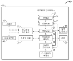
도 4는, 예를 들어, 도 3에 도시된 디스플레이 장치의 제어 로직으로서 사용하기에 적합한 예시적인 제어 로직의 블록도를 도시한다.
[0024]
도 5는 도 4에 도시된 제어 로직을 이용하여 디스플레이 상에 이미지를 생성하기 위한 예시적인 프로세스의 흐름도를 도시한다.
[0025]
도 6은 도 4에 도시된 제어 로직을 이용하여 디스플레이 상에 이미지를 생성하기 위한 다른 예시적인 프로세스의 흐름도를 도시한다.
[0026]
도 7은 디스플레이 상에 이미지를 형성하는 예시적인 프로세스의 흐름도를 도시한다.
[0027]
도 8은 디스플레이의 전력 소모를 감소시키는 예시적인 프로세스의 흐름도를 도시한다.
[0028]
도 9는 디스플레이의 전력 소모를 감소시키는 제 2 예시적인 프로세스의 흐름도를 도시한다.
[0029]
도 10은 원하는 전력 소모 타겟에 부분적으로 기초하여 선택되는 Q 값을 이용하여 이미지들을 출력하는 디스플레이의 예시적인 프로세스의 흐름도를 도시한다.
[0030]
도 11a 및 도 11b는 복수의 디스플레이 엘리먼트들을 포함하는 예시적인 디스플레이 디바이스의 시스템 블록도들을 도시한다.
[0031]
다양한 도면들에서의 동일한 참조 번호들 및 표기들은 동일한 엘리먼트들을 표시한다.[0019] FIG. 1A shows a schematic diagram of an exemplary direct-view microelectromechanical systems (MEMS) based display device.
[0020] FIG. 1B shows a block diagram of an exemplary host device.
[0021] FIGS. 2a and 2b illustrate views of an exemplary dual actuator shutter assembly.
[0022] FIG. 3 shows a block diagram of an exemplary display device.
[0023] FIG. 4 shows a block diagram of exemplary control logic suitable for use as control logic for the display device shown in FIG. 3, for example.
[0024] FIG. 5 illustrates a flow diagram of an exemplary process for generating an image on a display using the control logic illustrated in FIG. 4;
[0025] FIG. 6 shows a flow diagram of another exemplary process for generating an image on a display using the control logic shown in FIG.
[0026] FIG. 7 illustrates a flow diagram of an exemplary process for forming an image on a display.
[0027] Figure 8 shows a flow diagram of an exemplary process for reducing power consumption of a display.
[0028] FIG. 9 shows a flowchart of a second exemplary process for reducing power consumption of a display.
[0029] FIG. 10 shows a flow diagram of an exemplary process of a display that outputs images using a Q value selected based in part on a desired power consumption target.
[0030] Figures 11a and 11b illustrate system block diagrams of an exemplary display device including a plurality of display elements.
[0031] Like reference numbers and notations in the various figures indicate the same elements.
[0032] 아래의 상세한 설명은 본 개시물의 혁신적인 양상들을 설명하기 위한 특정한 구현들에 관한 것이다. 그러나, 당업자는 본원의 교시들이 다수의 상이한 방식들로 적용될 수 있다는 것을 쉽게 인식할 것이다. 설명된 구현들은, 동화상(이를테면, 비디오) 또는 정지 화상(이를테면, 스틸 이미지들)이든지 간에, 그리고 텍스트, 그래픽 또는 그림이든지 간에, 이미지의 디스플레이가 가능할 수 있는 임의의 디바이스, 장치 또는 시스템에서 구현될 수 있다. 본 개시내용에서 제공되는 개념들 및 예들은, 하나 또는 그 초과의 디스플레이 기술들로부터 피처들을 포함하는 디스플레이들 이외에도, 다양한 디스플레이들, 이를 테면, LCD(liquid crystal display)들, OLED(organic light-emitting diode) 디스플레이들, 전계 방출 디스플레이들, 및 EMS(electromechanical system)들 및 MEMS(microelectromechanical)-기반 디스플레이들에 적용가능 할 수 있다.[0032] The following detailed description is directed to specific implementations for illustrating innovative aspects of the disclosure. However, those skilled in the art will readily recognize that the teachings herein may be applied in a number of different ways. The described implementations may be implemented in any device, device, or system that may be capable of displaying images, whether moving pictures (e.g., video) or still pictures (such as still images) . The concepts and examples provided in this disclosure may be applied to a variety of displays, such as liquid crystal displays (LCDs), organic light-emitting devices (OLEDs), as well as displays including features from one or more display technologies diode displays, field emission displays, and electromechanical systems (EMS) and microelectromechanical (MEMS) -based displays.
[0033] 설명된 구현들이, 모바일 전화들, 멀티미디어 인터넷 인에이블 셀룰러 전화들, 모바일 텔레비전 수신기들, 무선 디바이스들, 스마트폰들, 블루투스® 디바이스들, 휴대 보조 단말기(PDA)들, 무선 전자 메일 수신기들, 핸드-헬드 또는 휴대용 컴퓨터들, 넷북들, 노트북들, 스마트북들, 태블릿들, 프린터들, 복사기들, 스캐너들, 팩시밀리 디바이스들, GPS(global positioning system) 수신기들/네비게이터들, 카메라들, 디지털 미디어 플레이어들(이를테면, MP3 플레이어들), 캠코더들, 게임 콘솔들, 손목 시계들, 웨어러블 디바이스, 시계들, 계산기들, 텔레비전 모니터들, 플랫 패널 디스플레이들, 전자 판독 디바이스들(예를 들어, e-리더들), 컴퓨터 모니터들, 오토 디스플레이들(이를 테면, 주행기록계 및 속도계 디스플레이들), 조종석 컨트롤들 및/또는 디스플레이들, 카메라 뷰 디스플레이들(예컨대, 차량의 후방 뷰 카메라의 디스플레이), 전자 사진들, 전자 게시판들 또는 간판(sign)들, 프로젝터들, 건축(architectural) 구조들, 마이크로파들, 냉장고들, 스테레오 시스템들, 카세트 레코더들 또는 플레이어들, DVD 플레이어들, CD 플레이어들, VCR들, 라디오들, 휴대용 메모리 칩들, 세탁기들, 건조기들, 세탁기/건조기들, 주차요금 징수기들(parking meters), (이를테면, 비-EMS(electromechanical system) 애플리케이션들은 물론, MEMS(microelectromechanical system)들 애플리케이션들을 비롯한 EMS 애플리케이션들에서의) 패키징, 심미적 구조들(이를테면, 한점의 보석 또는 의류 상의 이미지들의 디스플레이) 및 다양한 EMS 디바이스들과 같은, (그러나, 이들에 제한되지 않음) 다양한 전자 디바이스들에 포함되거나 또는 이들과 연관될 수 있다.[0033] It will be appreciated that the described implementations are applicable to mobile phones, multimedia Internet enabled cellular phones, mobile television receivers, wireless devices, smartphones, Bluetooth® devices, PDAs, wireless e-mail receivers, Scanners, facsimile devices, global positioning system (GPS) receivers / navigators, cameras, digital media, digital cameras, digital cameras, (E.g., MP3 players), camcorders, game consoles, wristwatches, wearable devices, clocks, calculators, television monitors, flat panel displays, electronic reading devices Readers), computer monitors, auto displays (such as odometer and speedometer displays), cockpit controls and / or displays, Electronic displays, electronic bulletin boards or signs, projectors, architectural structures, microwaves, refrigerators, stereo systems, and the like, Cassette recorders or players, DVD players, CD players, VCRs, radios, portable memory chips, washing machines, dryers, washer / dryers, parking meters, Such as packaging, aesthetic structures (e.g., display of one point of jewelry or clothing images), and various EMS devices, as well as electromechanical system (EMS) applications, as well as EMS applications including microelectromechanical systems , ≪ / RTI > but not limited to, various electronic devices.
[0034] 본원에서의 교시들은 또한, 전자 스위칭 디바이스들, 무선 주파수 필터들, 센서들, 가속도계들, 자이로스코프들, 움직임-감지 디바이스들, 자력계들, 가전제품에 대한 관성 컴포넌트들, 가전제품 물건들의 부품들, 버랙터들, 액정 디바이스들, 전기영동 디바이스들, 구동 방식들, 제조 프로세스들, 및 전자 테스트 장비와 같은 (그러나, 이들에 제한되지 않음) 비-디스플레이 애플리케이션들에서 사용될 수 있다. 따라서, 교시들은 도면들에 단독으로 도시한 구현들로 제한되는 것으로 의도되는 것이 아니라, 대신에, 당업자에게 쉽게 명백할 바와 같이, 넓은 응용가능성을 가진다.[0034] The teachings herein are also applicable to electronic switching devices, radio frequency filters, sensors, accelerometers, gyroscopes, motion-sensing devices, magnetometers, inertial components for consumer electronics, Display applications such as (but not limited to) liquid crystal devices, liquid crystal devices, electrophoretic devices, driving methods, manufacturing processes, and electronic test equipment. Accordingly, the teachings are not intended to be limited to the embodiments shown solely in the drawings, but instead have broad applicability, as will be readily apparent to those skilled in the art.
[0035] 멀티-프라이머리 디스플레이는, 색 영역 맵핑 함수에 따라 입력 픽셀 값들을 XYZ 컬러 공간으로 맵핑한 다음 XYZ 3자극 값들을 디스플레이의 프라이머리 컬러들과 연관된 컬러 서브필드들로 분해함으로써, 입력 이미지 데이터를 디스플레이에 의해 활용되는 다중-프라이머리 컬러 공간들로 변환하는 제어 로직을 포함할 수 있다. 예를 들어, 이러한 프로세스는 RGB 컬러 공간에서 인코딩된 이미지 프레임들을 RGBW 컬러 공간으로 변환하는데 사용될 수 있다.[0035] The multi-primary display maps the input pixel values to the XYZ color space according to the gamut mapping function and then decomposes the XYZ triad values into color subfields associated with the primary colors of the display, Primary color spaces that are utilized by the < / RTI > For example, this process can be used to convert encoded image frames in the RGB color space to RGBW color space.
[0036] 일부 구현들에서, 컬러 충실도를 유지하고 전력 효율을 향상시키기 위해서, 제어 로직은, 입력 이미지 픽셀 값들을 XYZ 색 3자극 공간으로 변환할 경우 이미지 채도 의존 색 영역 맵핑을 활용할 수 있다. 일부 구현들에서, 제어 로직은 채도 레벨 의존 색 영역 맵핑 룩업 테이블(LUT)을 생성함으로써 이미지 채도 의존 색 영역 맵핑을 구현할 수 있다. 채도 레벨은 파라미터 Q로 나타내어진다. 채도 레벨 의존 색 영역 맵핑 LUT는 적어도 2 개의 저장된 채도 레벨 의존(즉, Q-의존) 색 영역 맵핑 LUT들 사이의 값들을 보간함으로써 형성될 수 있다. 일부 구현들에서, 제어 로직은 채도 레벨 의존 분해 매트릭스를 이용하여 XYZ 3자극 값들을 다중-프라이머리 컬러 서브필드들로 분해할 수 있다.[0036] In some implementations, to maintain color fidelity and improve power efficiency, the control logic may utilize image saturation dependent color gamut mapping when converting input image pixel values to XYZ color triple stimulus space. In some implementations, the control logic may implement image saturation dependent color gamut mapping by creating a saturation level dependent color gamut mapping look-up table (LUT). The saturation level is represented by the parameter Q. The saturation level dependent color gamut mapping LUT may be formed by interpolating values between at least two stored saturation level dependent (i. E., Q-dependent) color gamut mapping LUTs. In some implementations, the control logic may decompose the XYZ tristimulus values into multiple-primary color subfields using a saturation level dependent decomposition matrix.
[0037] 일부 구현들에서, 채도 기반 색 영역 맵핑은 디스플레이의 전력 소모를 제어하도록 적응될 수 있다. 예를 들어, 이미지들은, 디바이스 비활동을 검출하는 것에 대한 응답으로 또는 저 배터리 상태를 검출하는 것에 대한 응답으로 저 채도(즉, 높은 Q 값)를 이용하여 색 영역 맵핑될 수 있다. 유사하게, 색 영역 맵핑에 이용되는 채도 레벨은 타겟 전력 소모 또는 배터리 수명을 유지하도록 조정될 수 있다.[0037] In some implementations, the chroma-based color gamut mapping may be adapted to control the power consumption of the display. For example, images may be gamut-mapped using low saturation (i.e. high Q values) in response to detecting device inactivity or in response to detecting low battery conditions. Similarly, the saturation level used for color gamut mapping can be adjusted to maintain target power consumption or battery life.
[0038] 본 개시내용에 설명된 요지의 특정 구현들은, 다음 잠재적인 이점들 중 하나 또는 그 초과의 것을 실현하기 위해서 구현될 수 있다. 채도 의존 색 영역 맵핑 프로세스를 사용하여 입력 픽셀 값들을 출력 픽셀 값들로 변환함으로써 색 충실도를 실질적으로 유지하면서 상당한 전력 절감들이 달성될 수 있다. 입력 픽셀 값들이 XYZ 컬러 공간의 XYZ 3자극 값들로 맵핑되도록 색 영역 맵핑 프로세스를 구현함으로써, 디스플레이의 제어 로직은, 결과적으로 디더링된 픽셀 XYZ 3자극 값들을 RGBW 강도 값들로 분해하기 전에 벡터 에러 확산 프로세스들을 더욱 용이하게 구현할 수 있다. XYZ 컬러 공간에서의 벡터 에러 확산은 RGBW 컬러 공간내 하나의 컬러 서브필드 디더링에 비해 화질을 상당히 개선시킬 수 있다.[0038] Certain implementations of the subject matter described in this disclosure may be implemented to realize one or more of the following potential advantages. Significant power savings can be achieved while substantially preserving color fidelity by converting input pixel values to output pixel values using a chroma-dependent color gamut mapping process. By implementing the gamut mapping process so that the input pixel values are mapped to the XYZ tristimulus values in the XYZ color space, the display's control logic will result in the vector error diffusion process Can be implemented more easily. Vector error diffusion in the XYZ color space can significantly improve picture quality compared to one color subfield dithering in the RGBW color space.
[0039] 일부 구현들에서, 색 영역 맵핑 프로세스는, 디스플레이가 내부에 통합되어 있는 디바이스의 배터리 수명을 유지하거나 또는 연장시키기 위해 전력이 디스플레이에 의해 소모되는 레이트를 제어하는데 이용될 수 있다. 서브프레임 감소와 같은 추가 전력 관리 피처들은 또한, 이미지 프레임을 디스플레이하기 위해 선택된 Q 값들 및/또는 디스플레이의 배터리 레벨에 기초하여 활용될 수 있다.[0039] In some implementations, the gamut mapping process may be used to control the rate at which power is consumed by the display to maintain or extend the battery life of the device in which the display is integrated. Additional power management features such as subframe reduction may also be utilized based on the Q values selected to display the image frame and / or the battery level of the display.
[0040]
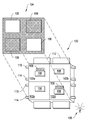
도 1a는 예시적인 직시형(direct-view) MEMS-기반 디스플레이 장치(100)의 개략도를 도시한다. 디스플레이 장치(100)는 행들 및 열들로 배열된 복수의 광 변조기들(102a-102d)(일반적으로 광 변조기들(102))을 포함한다. 디스플레이 장치(100)에서, 광 변조기들(102a 및 102d)은 광이 통과하도록 하는 개방 상태로 있다. 광 변조기들(102b 및 102c)은 광의 통과를 차단하는 폐쇄상태로 있다. 광 변조기들(102a-102d)의 상태들을 선택적으로 세팅함으로써, 램프 또는 램프들(105)에 의해 조명되는 경우, 백릿(backlit) 디스플레이에 대한 이미지(104)를 형성하는데 디스플레이 장치(100)가 활용될 수 있다. 다른 구현에서, 장치(100)는 장치의 전방으로부터 발생하는 주변 광의 반사에 의해 이미지를 형성할 수 있다. 다른 구현에서, 장치(100)는 디스플레이의 전방에 포지셔닝된 램프 또는 램프들로부터의 광의 반사에 의해, 즉 전면 광(front light)의 사용에 의해 이미지를 형성할 수 있다.[0040]
FIG. 1A illustrates a schematic diagram of an exemplary direct-view MEMS-based
[0041]
일부 구현들에서, 각각의 광 변조기(102)는 이미지(104)의 픽셀(106)에 대응한다. 일부 다른 구현들에서, 디스플레이 장치(100)는 이미지(104)내에 픽셀(106)을 형성하기 위해 복수의 광 변조기들을 활용할 수 있다. 예를 들어, 디스플레이 장치(100)는 3 컬러-특정 광 변조기들(102)을 포함할 수 있다. 특정 픽셀(106)에 대응하는 컬러-특정 광 변조기들(102) 중 하나 또는 그 초과의 것을 선택적으로 개방함으로써, 디스플레이 장치(100)는 이미지(104)에 컬러 픽셀(106)을 생성할 수 있다. 다른 예에서, 디스플레이 장치(100)는 이미지(104)의 휘도 레벨을 제공하기 위해 픽셀(106) 당 2개 이상의 광 변조기들(102)을 포함한다. 이미지에 대하여, 픽셀은 이미지의 해상도에 의해 정의되는 최소 픽처 엘리먼트(picture element)에 대응한다. 디스플레이 장치(100)의 구조적 컴포넌트들에 대하여, 용어 픽셀은 이미지의 단일 픽셀을 형성하는 광을 변조시키기 위해 활용되는 결합된 기계 및 전기 컴포넌트들을 지칭한다.[0041]
In some implementations, each optical modulator 102 corresponds to a
[0042]
디스플레이 장치(100)는 그것이 프로젝션 애플리케이션들에서 전형적으로 발견되는 이미징 광학계들을 포함하지 않을 수 있다는 점에서 직시형 디스플레이이다. 프로젝션 디스플레이에서, 디스플레이 장치의 표면상에 형성되는 이미지는 스크린상에 또는 벽 상에 투영된다. 디스플레이 장치는 투영된 이미지보다 실질적으로 더 작다. 직시형 디스플레이에서, 디스플레이상에서 보여지는 밝기(brightness) 및/또는 콘트라스트(contrast)를 향상시키기 위하여 광 변조기들 및 선택적으로 백라이트 또는 전면 광을 포함하는 디스플레이 장치를 직접 봄으로써 이미지가 보여질 수 있다.[0042]
[0043] 직시형 디스플레이들은 투과 모드 또는 반사 모드로 동작할 수 있다. 투과 디스플레이에서, 광 변조기들은 디스플레이 뒤에 포지셔닝되는 램프 또는 램프들로부터 발생하는 광을 필터링하거나 또는 선택적으로 차단한다. 램프들로부터의 광은 각각의 픽셀이 균일하게 조명될 수 있도록 광가이드 또는 백라이트에 선택적으로 주입된다. 투과 직시형 디스플레이들은 광 변조기들을 포함하는 하나의 기판이 백라이트 위로 포지셔닝되는 샌드위치 어셈블리 어레인지먼트를 가능하게 하기 위해 투명 기판들상에 종종 구축된다. 일부 구현들에서, 투명 기판은 유리 기판(때때로 유리 플레이트 또는 패널로 지칭됨) 또는 플라스틱 기판일 수 있다. 유리 기판은, 예를 들어, 붕규산 유리, 와인 유리, 용융 실리카, 소다 석회 유리, 석영, 인공 석영, 파이렉스(Pyrex) 또는 다른 적합한 유리 재료일 수 있거나 이를 포함할 수 있다.[0043] The direct view displays can operate in a transmissive mode or a reflective mode. In a transmissive display, the light modulators filter or selectively block light from lamps or lamps positioned behind the display. The light from the lamps is selectively injected into the light guide or backlight so that each pixel can be uniformly illuminated. Transparent direct displays are often built on transparent substrates to enable sandwich assembly arrangements where one substrate, including optical modulators, is positioned over the backlight. In some implementations, the transparent substrate may be a glass substrate (sometimes referred to as a glass plate or panel) or a plastic substrate. The glass substrate can be, for example, or comprise borosilicate glass, wine glass, fused silica, soda lime glass, quartz, artificial quartz, pyrex or other suitable glass materials.
[0044]
각각의 광 변조기(102)는 셔터(108) 및 어퍼처(109)를 포함할 수 있다. 이미지(104)의 픽셀(106)을 조명하기 위해, 셔터(108)는 광이 어퍼처(109)를 통과하도록 포지셔닝된다. 픽셀(106)을 미조명 상태(unlit)로 유지하기 위해, 셔터(108)는 어퍼처(109)를 통한 광의 통과를 차단하도록 포지셔닝된다. 어퍼처(109)는 각각의 광 변조기(102)의 반사 또는 광-흡수 물질을 통해 패터닝되는 개구부에 의해 정의된다.[0044]
Each of the optical modulators 102 may include a
[0045] 디스플레이 장치는 또한 셔터들의 이동을 제어하기 위해 기판에 그리고 광 변조기들에 결합되는 제어 매트릭스를 포함한다. 제어 매트릭스는 픽셀들의 행 당 적어도 하나의 기록-인에이블 상호접속부(110)(또한 스캔-라인 상호접속부라 지칭됨), 픽셀들의 각각의 열에 대한 하나의 데이터 상호접속부(112), 및 디스플레이 장치(100)의 모든 픽셀들에 또는 적어도 다수의 열들 및 다수의 행들 모두로부터의 픽셀들에 공통 전압을 제공하는 하나의 공통 상호접속부(114)를 포함하는, 일련의 전기적 상호접속부들(예를 들어, 상호접속부들(110, 112 및 114))을 포함한다. 적절한 전압(기록-인에이블 전압, Vwe)의 인가에 대한 응답으로, 픽셀들의 정해진 행에 대한 기록-인에이블 상호접속부(110)는 새로운 셔터 이동 명령들을 받아들이도록 행의 픽셀들을 준비시킨다. 데이터 상호접속부들(112)은 데이터 전압 펄스들의 형태로 새로운 이동 명령들을 통신한다. 일부 구현들에서, 데이터 상호접속부들(112)에 인가되는 데이터 전압 펄스들은 셔터들의 정전기 이동에 직접적으로 기여한다. 일부 다른 구현들에서, 데이터 전압 펄스들은, 통상적으로 데이터 전압들보다 크기가 더 큰 개별 구동 전압들의 광 변조기들(102)로의 인가를 제어하는 스위치들, 예를 들어 트랜지스터들 또는 다른 비-선형 회로 엘리먼트들을 제어한다. 이들 구동 전압들의 인가는 셔터들(108)의 정전기 구동 이동을 발생시킨다.[0045] The display device also includes a control matrix coupled to the substrate and to the light modulators to control the movement of the shutters. The control matrix includes at least one write-enable interconnect 110 (also referred to as a scan-line interconnect), a
[0046] 제어 매트릭스는 또한, 각각의 셔터 어셈블리와 연관되는 트랜지스터 및 캐패시터와 같은 회로를 포함할 수 있으며, 이것으로 제한되지 않는다. 일부 구현들에서, 각각의 트랜지스터의 게이트는 스캔 라인 상호접속부에 전기적으로 연결될 수 있다. 일부 구현들에서, 각각의 트랜지스터의 소스는 대응하는 데이터 상호접속부에 전기적으로 연결될 수 있다. 일부 구현들에서, 각각의 트랜지스터의 드레인은 대응하는 캐패시터의 전극에 그리고 대응하는 액추에이터의 전극에 전기적으로 병렬로 연결될 수 있다. 일부 구현들에서, 각각의 셔터 어셈블리와 연관된 캐패시터 및 액추에이터의 다른 전극은 공통 또는 접지 전위에 연결될 수 있다. 일부 다른 구현들에서, 트랜지스터는 반도체 다이오드, 또는 금속-절연체-금속 스위칭 엘리먼트로 대체될 수 있다.[0046] The control matrix may also include, but is not limited to, circuitry such as transistors and capacitors associated with each shutter assembly. In some implementations, the gate of each transistor may be electrically coupled to the scan line interconnect. In some implementations, the source of each transistor may be electrically coupled to a corresponding data interconnect. In some implementations, the drain of each transistor may be electrically connected in parallel to the electrodes of the corresponding capacitors and to the electrodes of the corresponding actuators. In some implementations, the capacitor associated with each shutter assembly and the other electrode of the actuator may be connected to a common or ground potential. In some other implementations, the transistor may be replaced by a semiconductor diode, or a metal-insulator-metal switching element.
[0047]
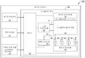
도 1b는 예시적인 호스트 디바이스(120)(즉, 셀 폰, 스마트 폰, PDA, MP3 플레이어, 태블릿, e-리더, 넷북, 노트북, 시계, 웨어러블 디바이스, 랩탑, 텔레비전, 또는 다른 전자 디바이스)의 블록도의 예를 도시한다. 호스트 디바이스(120)는 디스플레이 장치(128)(이를 테면, 도 1a에 도시된 디스플레이 장치(100)), 호스트 프로세서(122), 환경 센서들(124), 사용자 입력 모듈(126), 및 전력 소스를 포함한다.[0047]
1B is a block diagram of an exemplary host device 120 (i.e., a cell phone, a smartphone, a PDA, an MP3 player, a tablet, an e-reader, a netbook, a notebook, a watch, a wearable device, a laptop, Fig. The
[0048]
디스플레이 장치(128)는 복수의 스캔 드라이버들(130)(또한 기록 인에이블 전압 소스들로 지칭됨), 복수의 데이터 드라이버들(132)(또한 데이터 전압 소스들로 지칭됨), 제어기(134), 공통 드라이버들(138), 램프들(140-146), 램프 드라이버들(148) 및 도 1a에 도시된 광 변조기들(102)과 같은 디스플레이 엘리먼트들의 어레이(150)를 포함한다. 스캔 드라이버들(130)은 스캔-라인 상호접속부들(131)에 기록 인에이블 전압들을 인가한다. 데이터 드라이버들(132)은 데이터 상호접속부들(133)에 데이터 전압들을 인가한다.[0048]
The
[0049]
디스플레이 장치의 일부 구현들에서, 데이터 드라이버들(132)은 특히 이미지(104)의 휘도 레벨이 아날로그 방식으로 유도되어야 하는 경우에, 아날로그 데이터 전압들을 디스플레이 엘리먼트들의 어레이(150)에 제공할 수 있다. 아날로그 동작에서, 디스플레이 엘리먼트들은 다양한 중간 전압들이 데이터 상호접속부들(133)을 통해 인가될 때, 결과적으로 발생된 이미지에서 다양한 중간 조명 상태들 또는 휘도 레벨들이 발생하도록 설계된다. 일부 다른 구현들에서, 데이터 드라이버들(132)은 축소된 세트, 이를 테면, 2개, 3개 또는 4개의 디지털 전압 레벨들을 데이터 상호접속부들(133)에 인가할 수 있다. 디스플레이 엘리먼트들이 셔터-기반 광 변조기들, 이를 테면, 도 1a에 도시된 광 변조기들(102)인 구현들에서, 이들 전압 레벨들은 디지털 방식으로, 셔터들(108) 각각에 개방 상태, 폐쇄 상태 또는 다른 개별 상태를 세팅하도록 설계된다. 일부 구현들에서, 드라이버들은 아날로그 모드와 디지털 모드를 전환할 수 있다.[0049]
In some implementations of the display device, the data drivers 132 may provide analog data voltages to the array of
[0050]
스캔 드라이버들(130) 및 데이터 드라이버들(132)은 디지털 제어기 회로(134)(제어기(134)로도 지칭됨)에 연결된다. 제어기(134)는, 일부 구현들에서, 행들 및 이미지 프레임들에 의해 그룹화되는, 미리 결정될 수 있는 시퀀스들로 편성되는 데이터를 주로 직렬 방식으로 데이터 드라이버들(132)에 송신한다. 데이터 드라이버들(132)은 직렬-대-병렬(series to parallel) 데이터 컨버터들, 레벨 시프팅 및 일부 애플리케이션들에 대해서는 디지털-대-아날로그 전압 컨버터들을 포함할 수 있다.[0050]
[0051]
디스플레이 장치는, 공통 전압 소스들로도 지칭되는, 공통 드라이버들(138)의 세트를 선택적으로 포함한다. 일부 구현들에서, 공통 드라이버들(138)은 예를 들어, 일련의 공통 상호접속부들(139)에 전압을 공급함으로써, 디스플레이 엘리먼트들의 어레이(150) 내의 모든 디스플레이 엘리먼트들에 DC 공통 전위(potential)를 제공한다. 일부 다른 구현들에서, 제어기(134)로부터의 커맨드들에 따라, 공통 드라이버들(138)은 예를 들어 어레이의 다수의 행들 및 열들의 모든 디스플레이 엘리먼트들의 동시적 작동을 구동 및/또는 개시시킬 수 있는 글로벌 구동 펄스들인, 전압 펄스들 또는 신호들을 디스플레이 엘리먼트들의 어레이(150)에 공급(issue)한다.[0051]
The display device optionally includes a set of
[0052]
상이한 디스플레이 기능들을 위한 드라이버들(이를 테면, 스캔 드라이버들(130), 데이터 드라이버들(132) 및 공통 드라이버들(138)) 각각은 제어기(134)에 의해 시간-동기화될 수 있다. 제어기(134)로부터의 타이밍 커맨드들은 램프 드라이버들(148)을 통한 적색, 녹색, 청색 및 백색 램프들(각각, 140, 142, 144 및 146)의 조명, 디스플레이 엘리먼트들의 어레이(150) 내의 특정 행들의 기록-인에이블 및 시퀀싱, 데이터 드라이버들(132)로부터의 전압들의 출력, 및 디스플레이 엘리먼트 작동을 위해 제공하는 전압들의 출력을 조정한다. 일부 구현들에서, 램프들은 LED(light emitting diode)들이다.[0052]
Each of the drivers (e.g., scan
[0053]
제어기(134)는 시퀀싱 또는 어드레싱 방식을 결정하는데, 이 시퀀싱 또는 어드레싱 방식에 의해, 디스플레이 엘리먼트들 각각은 새로운 이미지(104)에 적절한 조명 레벨들로 재-세팅될 수 있다. 새로운 이미지들(104)은 주기적 간격들로 세팅될 수 있다. 예를 들어, 비디오 디스플레이들에 대해, 비디오의 프레임들 또는 컬러 이미지들은 10 내지 300 헤르츠(Hz) 범위의 주파수들로 리프레시된다(refreshed). 일부 구현들에서, 디스플레이 엘리먼트들의 어레이(150)에 대한 이미지 프레임의 세팅은, 교번하는 이미지 프레임들이 교번하는 일련의 컬러들, 예를 들어 적색, 녹색, 청색 및 백색으로 조명되도록, 램프들(140, 142, 144 및 146)의 조명과 동기화된다. 각각의 개별 컬러에 대한 이미지 프레임들은 컬러 서브프레임들로 지칭된다. 필드 순차 컬러 방법으로서 지칭되는 이 방법에서, 컬러 서브프레임들이 20 Hz를 초과한 주파수들에서 교번되는 경우에, HVS(human visual system)는, 이미지가 광범위하고 연속적인 컬러들의 범위를 갖는다는 인식으로, 교번하는 프레임 이미지들을 평균화할 것이다. 일 다른 구현들에서, 램프들은, 적색, 녹색, 청색 및 백색 이외의 프라이머리 컬러들을 활용할 수 있다. 일부 구현들에서, 프라이머리 컬러들을 지닌 4개 미만 또는 4개 초과의 램프들이 디스플레이 장치(128)에서 활용될 수 있다.[0053]
The
[0054]
디스플레이 장치(128)가, 셔터들, 이를 테면, 도 1a에 도시된 셔터들(108)을 개방 상태와 폐쇄 상태 사이에서 디지털 스위칭하도록 설계되는 일부 구현들에서, 제어기(134)는 시분할 그레이 스케일의 방법에 의해 이미지를 형성한다. 일부 다른 구현들에서, 디스플레이 장치(128)는 픽셀 당 다수의 디스플레이 엘리먼트들의 이용을 통해 그레이 스케일을 제공할 수 있다.[0054]
In some implementations in which the
[0055]
일부 구현들에서, 이미지 상태에 대한 데이터는, 스캔 라인들로도 지칭되는 개별 행들의 순차적인 어드레싱에 의해 제어기(134)에 의해 디스플레이 엘리먼트의 어레이(150)에 로딩된다. 시퀀스의 각각의 행 또는 스캔 라인에 대해, 스캔 드라이버(130)는 디스플레이 엘리먼트들의 어레이(150)의 해당 행에 대한 기록 인에이블 상호접속부(131)에 기록-인에이블 전압을 인가하고, 후속하여 데이터 드라이버(132)는 어레이의 선택된 행의 각각의 열에 대해, 원하는 셔터 상태들에 대응하는 데이터 전압들을 공급한다. 이 어드레싱 프로세스는, 데이터가 디스플레이 엘리먼트들의 어레이(150)의 모든 행들에 대해 로딩될 때까지 반복될 수 있다. 일부 구현들에서, 데이터 로딩을 위해 선택된 행들의 시퀀스는 선형적이어서, 디스플레이 엘리먼트들의 어레이(150)의 최상부로부터 최하부로 진행한다. 일부 다른 구현들에서, 선택된 행들의 시퀀스는 잠재적인 시각적 아티팩트(visual artifact)들을 완화시키기 위해 의사-랜덤화된다. 그리고, 일부 다른 구현들에서, 시퀀싱은 블록들 단위로 편성되며, 여기서, 일 블록에 대해, 이미지의 특정 부분(certain fraction)에 대한 데이터가 디스플레이 엘리먼트들의 어레이(150)로 로딩된다. 예를 들어, 시퀀스는 디스플레이 엘리먼트들(150)의 어레이의 매 5번째 행을 차례로 어드레싱하도록 구현될 수 있다.[0055]
In some implementations, the data for the image state is loaded into the array of
[0056]
일부 구현들에서, 이미지 데이터를 디스플레이 엘리먼트들의 어레이(150)에 로딩하기 위한 어드레싱 프로세스는 디스플레이 엘리먼트들을 작동시키는 프로세스로부터 시간적으로 분리된다. 이러한 구현에서, 디스플레이 엘리먼트들의 어레이(150)는 각각의 디스플레이 엘리먼트에 대한 데이터 메모리 엘리먼트들을 포함할 수 있으며, 제어 매트릭스는, 메모리 엘리먼트들에 저장되는 데이터에 따라 디스플레이 엘리먼트들의 동시 작동을 개시하기 위해서, 공통 드라이버(138)로부터의 트리거 신호들을 반송하기 위한 글로벌 작동 상호접속부(global actuation interconnect)를 포함할 수 있다.[0056]
In some implementations, the addressing process for loading image data into the array of
[0057]
일부 구현들에서, 디스플레이 엘리먼트들의 어레이(150) 및 디스플레이 엘리먼트들을 제어하는 제어 매트릭스는 직사각형 행들 및 열들이 아닌 구성들로 배열될 수 있다. 예를 들어, 디스플레이 엘리먼트들은 6각형 어레이들 또는 곡선형 행들 및 열들로 배열될 수 있다.[0057]
In some implementations, the control matrix that controls the array of
[0058]
호스트 프로세서(122)는 일반적으로 호스트 디바이스(120)의 동작들을 제어한다. 예를 들어, 호스트 프로세서(122)는 휴대용 전자 디바이스를 제어하기 위한 범용 또는 특수 목적 프로세서일 수 있다. 호스트 디바이스(120) 내에 포함된 디스플레이 장치(128)와 관련하여, 호스트 프로세서(122)는 이미지 데이터 뿐만 아니라 호스트 디바이스(120)에 대한 추가 데이터를 출력한다. 이러한 정보는 주변 광 또는 온도와 같은, 환경 센서들(124)로부터의 데이터; 예를 들어, 호스트 디바이스의 전원에 남아있는 전력량 또는 호스트의 동작 모드를 비롯한, 호스트 디바이스(120)에 관한 정보; 이미지 데이터의 컨텐츠에 관한 정보; 이미지 데이터의 타입에 대한 정보; 및/또는 이미징 모드를 선택하는데 사용하기 위한 디스플레이 장치(128)에 대한 명령들을 포함할 수 있다.[0058]
The
[0059]
일부 구현들에서, 사용자 입력 모듈(126)은, 사용자의 개인 선호도들을 직접적으로, 또는 호스트 프로세서(122)를 통해 제어기(134)로 전달할 수 있게 한다. 일부 구현들에서, 사용자 입력 모듈(126)은, 사용자가 개인 선호들, 예를 들어, 컬러, 콘트라스트, 전력, 밝기, 컨텐츠 및 다른 디스플레이 셋팅들 및 파라미터 선호들을 입력하는 소프트웨어에 의해 제어된다. 일부 다른 구현들에서, 사용자 입력 모듈(126)은, 사용자가 개인 선호들을 입력하는 하드웨어에 의해 제어된다. 일부 구현들에서, 사용자는 음성 명령들, 하나 또는 그 초과의 버튼들, 스위치들 또는 다이얼들을 통해 또는 터치-기능을 이용하여 이러한 선호도들을 입력할 수 있다. 제어기(134)에 대한 복수의 데이터 입력들은, 최적의 이미징 특성들에 대응하는 다양한 드라이버들(130, 132, 138 및 148)에 데이터를 제공할 것을 제어기에 지시한다.[0059]
In some implementations, the
[0060]
환경 센서 모듈(124)은 또한 호스트 디바이스(120)의 일부로서 포함될 수 있다. 환경 센서 모듈(124)은 온도 및/또는 주변 조명(lighting) 조건들과 같은 주변 환경에 대한 데이터를 수신할 수 있다. 센서 모듈(124)은, 예를 들어, 디바이스가 실내 또는 사무실 환경에서 동작하고 있는지, 밝은 대낮에 실외 환경에서 동작하고 있는지, 그리고 야간에 실외 환경에서 동작하고 있는지를 구별하도록 프로그래밍될 수 있다. 센서 모듈(124)은 이 정보를 디스플레이 제어기(134)에 통신하여, 제어기(134)는 주변 환경에 응답하여 보는 조건들을 최적화할 수 있다.[0060]
The
[0061]
도 2a 및 도 2b는 예시적인 이중 액추에이터 셔터 어셈블리(200)의 도면들을 도시한다. 도 2a에 도시된 바와 같이, 이중 액추에이터 셔터 조립체(200)는 개방 상태로 있다. 도 2b는 폐쇄된 상태의 이중 액추에이터 셔터 조립체(200)를 도시한다. 셔터 조립체(200)는 셔터(206)의 양측에 액츄에이터들(202, 204)을 포함한다. 각각의 액추에이터(202 및 204)는 독립적으로 제어된다. 제 1 액추에이터, 셔터-개방 액추에이터(202)는 셔터(206)를 개방시키는 역할을 한다. 제 2 대향 액추에이터, 셔터-폐쇄 액추에이터(204)는 셔터(206)를 폐쇄하는 역할을 한다. 액추에이터(202 및 204) 각각은 순응성 빔 전극 액추에이터들로서 구현될 수 있다. 액추에이터들(202 및 204)은, 셔터가 서스펜딩되는 동안 어퍼처 층(207)에 평행한 평면에서 셔터(206)를 실질적으로 구동시킴으로써 셔터(206)를 개방하고 폐쇄한다. 셔터(206)는, 액추에이터들(202 및 204)에 부착된 앵커들(208)에 의해 어퍼처 층(207)에 걸쳐 단거리에 서스펜딩된다. 이동 축을 따라 셔터(206)의 양 단부들에 부착된 액추에이터들(202, 204)을 구비하는 것은 셔터(206)의 평면 모션을 벗어나는 것을 감소시키고 그 모션을 기판(미도시)에 평행한 평면에 대해 실질적으로 한정한다.[0061]
2A and 2B illustrate views of an exemplary dual
[0062]
도시된 구현에서, 셔터(206)는 광이 통과할 수 있는 2개의 셔터 어퍼처들(212)을 포함한다. 어퍼처 층(207)은 3개의 어퍼처들(209)의 세트를 포함한다. 도 2a에서, 셔터 조립체(200)는 개방 상태로 있고, 그에 따라, 셔터-개방 액추에이터(202)가 작동되었고, 셔터-폐쇄 액추에이터(204)가 그의 릴렉스 포지션에 있고, 셔터 어퍼처들(212)의 중심선들이 어퍼처 층 어퍼처들(209) 중 2개의 중심선들과 일치한다. 도 2b에서, 셔터 조립체(200)가 폐쇄 상태로 이동되었고, 그에 따라서, 셔터-개방 액추에이터(202)가 그의 릴렉스 포지션에 있고, 셔터-폐쇄 액추에이터(204)가 작동되었고, 셔터(206)의 광 차단 부분들은 이제, 어퍼처들(209)(점선들로 도시됨)을 통해 광의 투과를 차단하기 위한 포지션에 있다.[0062]
In the illustrated embodiment, the
[0063]
각각의 어퍼처는 그 둘레 주위에 적어도 하나의 에지를 갖는다. 예를 들어, 직사각형 어퍼처들(209)은 4개의 에지들을 갖는다. 원형, 타원형(elliptical), 오벌(oval), 또는 다른 만곡된 어퍼처들이 어퍼처 층(207)에 형성되는 일부 구현들에서, 각각의 어퍼처는 단일 에지를 가질 수 있다. 일부 다른 구현들에서, 어퍼처들은 수학적 의미에서 분리되거나 해체될 필요가 없지만, 대신 연결될 수 있다. 즉, 어퍼처의 부분들 또는 정형된 섹션들은 각각의 셔터와의 대응관계를 유지할 수 있지만, 이러한 섹션들 중 여러 개는, 어퍼처의 단일 연속 둘레가 다중 셔터들에 의해 공유되도록 연결될 수 있다.[0063]
Each aperture has at least one edge around its perimeter. For example, the
[0064]
다양한 출사각들을 갖는 광이 개방 상태에서 어퍼처들(212 및 209)을 통해 통과할 수 있게 하기 위해, 셔터 어퍼처들(212)의 폭 또는 크기는 어퍼처 층(207)의 어퍼처들(209)의 대응하는 폭 또는 크기보다 더 크게 설계될 수 있다. 폐쇄 상태에서 광이 빠져나가는 것을 효과적으로 방지하기 위해, 셔터(206)의 광 차단 부분들은 어퍼처들(209)의 에지들과 중첩되도록 설계될 수 있다. 도 2b는, 일부 구현들에서, 셔터(206) 내의 광 차단 부분들의 에지와 어퍼처 층(207)에 형성된 어퍼처(209)의 일 에지 사이에서 미리정의될 수 있는 중첩부(216)를 도시한다.[0064]
The width or size of the
[0065]
정전식 액추에이터들(202 및 204)은, 그들의 전압-변위 거동이 셔터 어셈블리(200)에 쌍안정 특성을 제공하도록 설계된다. 셔터-개방 및 셔터-폐쇄 액추에이터들 각각에 대해, 작동 전압 미만의 다양한 전압들이 존재하며, 이러한 전압이 (셔터가 개방 또는 폐쇄 상태에 있으면서) 액추에이터가 폐쇄 상태에 있는 동안 인가되면, 대향 액추에이터에 구동 전압이 인가된 후에도, 액추에이터 폐쇄 상태와 셔터 포지션을 유지할 것이다. 이러한 반대되는 힘에 대해 셔터의 포지션을 유지하는데 필요로 되는 최소 전압을 유지 전압(Vm)이라 지칭한다.[0065]
The
[0066]
도 3은 예시적인 디스플레이 장치(300)의 블록도를 도시한다. 디스플레이 장치(300)는 호스트 디바이스(302) 및 디스플레이 모듈(304)을 포함한다. 호스트 디바이스(302)는 호스트 디바이스(120)의 일 예일 수 있고, 디스플레이 모듈(304)은 디스플레이 장치(128)의 일 예일 수 있으며, 둘 모두는 도 1b에 도시된다. 호스트 디바이스(302)는 복수의 전자 디바이스들 중 임의의 것, 이를 테면, 휴대 전화, 스마트 폰, 시계, 태블릿 컴퓨터, 랩탑 컴퓨터, 데스크탑 컴퓨터, 텔레비전, 셋톱 박스, DVD 또는 미디어 플레이어, 또는 아래의 도 11a 및 도 11b에 도시된 디스플레이 디바이스(40)와 유사하게, 디스플레이에 그래피컬 출력을 제공하는 임의의 다른 디바이스일 수 있다. 일반적으로, 호스트 디바이스(302)는 디스플레이 모듈(304) 상에 디스플레이될 이미지 데이터를 위한 소스로서의 역할을 한다.[0066]
FIG. 3 shows a block diagram of an
[0067]
디스플레이 모듈(304)은 제어 로직(306), 프레임 버퍼(308), 디스플레이 엘리먼트들의 어레이(310), 디스플레이 드라이버(312) 및 백라이트(314)를 더 포함한다. 일반적으로, 제어 로직(306)은 호스트 디바이스(302)로부터 수신된 이미지 데이터를 프로세싱하는 역할을 하고 디스플레이 드라이버들(312), 디스플레이 엘리먼트의 어레이(310) 및 백라이트(314)를 제어하여 이미지 데이터에 인코딩된 이미지들을 함께 생성한다. 도 3에 도시된 제어 로직(306), 프레임 버퍼(308), 디스플레이 엘리먼트들의 어레이(310) 및 디스플레이 드라이버들(312)은, 일부 구현들에서, 아래의 도 11a 및 도 11b에 도시된 드라이버 제어기(29), 프레임 버퍼(28), 디스플레이 어레이(30) 및 어레이 드라이버들(22)과 유사할 수 있다. 제어 로직(306)의 기능은 도 5 내지 도 10과 관련하여 이하에서 추가로 설명된다.[0067]
The
[0068]
일부 구현들에서, 도 3에 도시된 바와 같이, 제어 로직(306)의 기능은 마이크로프로세서(316)와 인터페이스(I/F) 칩(318) 사이에서 분할된다. 일부 구현들에서, 인터페이스 칩(318)은 통합 회로 로직 디바이스, 이를 테면, ASIC(application specific integrated circuit)으로 구현된다. 일부 구현들에서, 마이크로프로세서(316)는 제어 로직(306)의 이미지 프로세싱 기능의 전부 또는 실질적으로 전부를 수행하도록 구성된다. 이외에도, 마이크로프로세서(316)는 디스플레이 모듈(304)이 수신된 이미지들을 생성하는데 사용하기 위한 적절한 출력 시퀀스를 결정하도록 구성될 수 있다. 예를 들어, 마이크로프로세서(316)는 수신된 이미지 데이터에 포함된 이미지 프레임들을 이미지 서브프레임들의 세트로 변환하도록 구성될 수 있다. 각각의 이미지 서브프레임은 컬러 및 가중치와 연관될 수 있으며, 디스플레이 엘리먼트들의 어레이(310) 내의 디스플레이 엘리먼트들 각각의 원하는 상태들을 포함한다. 마이크로프로세서(316)는 또한, 주어진 이미지 프레임을 생성하기 위해 디스플레이할 이미지 서브 프레임들의 수, 이미지 서브프레임들이 디스플레이될 순서, 각각의 서브프레임에서 디스플레이 엘리먼트들을 어드레싱하는 것과 연관된 타이밍 파라미터들, 및 이미지 서브프레임들 각각에 대해 적절한 가중치를 구현하는 것과 연관된 파라미터들을 결정하도록 구성될 수 있다. 이들 파라미터들은, 다양한 구현들에서, 각각의 이미지 서브프레임들 각각에 조명되는 지속 기간 및 그러한 조명의 강도를 포함할 수 있다. 이들 파라미터의 컬렉션(즉, 서브프레임들의 수, 이들 출력의 순서 및 타이밍, 및 각각의 서브 프레임에 대한 이들의 가중치 구현 파라미터들)은 "출력 시퀀스"로 지칭될 수 있다.[0068]
In some implementations, the functionality of the
[0069]
인터페이스 칩(318)은 디스플레이 모듈(304)의 보다 일반적인 동작들을 수행할 수 있다. 동작들은 프레임 버퍼(308)로부터 이미지 서브프레임들을 리트리빙하는 것 및 리트리빙된 이미지 서브프레임과 마이크로프로세서(316)에 의해 결정된 출력 시퀀스에 대한 응답으로 디스플레이 드라이버들(312) 및 백라이트(314)로 제어 신호들을 출력하는 것을 포함할 수 있다. 일부 다른 구현들에서, 마이크로프로세서(316) 및 인터페이스 칩(318)의 기능은, 마이크로프로세서, ASIC, 필드 프로그램가능 게이트 어레이(FPGA) 또는 다른 프로그램가능 로직 디바이스의 형태를 취할 수 있는 단일 로직 디바이스로 결합된다. 예를 들어, 마이크로프로세서(316) 및 인터페이스 칩(318)의 기능은 도 11b에 도시된 프로세서(21)에 의해 구현될 수 있다. 일부 다른 구현들에서, 마이크로프로세서(316) 및 인터페이스 칩(318)의 기능은, 하나 또는 그 초과의 마이크로프로세서들, ASIC들, FPGA들, DSP(digital signal processor)들 또는 다른 로직 디바이스들을 포함하는 다수의 로직 디바이스들 간에 다른 방식들로 분할될 수 있다.[0069]
The
[0070]
프레임 버퍼(308)는 임의의 휘발성 또는 비휘발성 집적 회로 메모리, 이를 테면, DRAM, 고속 캐시 메모리, 또는 플래시 메모리(예를 들어, 프레임 버퍼(308)는 도 11b에 도시된 프레임 버퍼(28)와 유사할 수 있음)일 수 있다. 일부 다른 구현들에서, 인터페이스 칩(318)은 프레임 버퍼(308)로 하여금 데이터 신호들을 디스플레이 드라이버들(312)로 직접 출력하게 한다. 프레임 버퍼(308)는 적어도 하나의 이미지 프레임과 연관된 컬러 서브필드 데이터 및 서브프레임 데이터를 저장할 수 있는 충분한 용량을 갖는다. 일부 구현들에서, 프레임 버퍼(308)는 단일 이미지 프레임과 연관된 컬러 서브필드 데이터 및 서브프레임 데이터를 저장할 수 있는 충분한 용량을 갖는다. 일부 다른 구현들에서, 프레임 버퍼(308)는 적어도 2개의 이미지 프레임들과 연관된 컬러 서브필드 데이터 및 서브프레임 데이터를 저장하기에 충분한 용량을 갖는다. 이러한 여분의 메모리 용량은, 이전에 수신된 이미지 프레임이 디스플레이 엘리먼트들의 어레이(310)를 통해 디스플레이되는 동안 더욱 최근에 수신된 이미지 프레임과 연관된 이미지 데이터의 마이크로프로세서(316)에 의한 부가적인 프로세싱을 가능하게 한다.[0070]
[0071]
일부 구현들에서, 디스플레이 모듈(304)은 다수의 메모리 디바이스들을 포함한다. 예를 들어, 디스플레이 모듈(304)은, 서브필드 데이터를 저장하기 위해, 하나의 메모리 디바이스, 이를 테면, 마이크로프로세서(316)와 직접 연관된 메모리를 포함할 수 있고, 프레임 버퍼(308)는 서브프레임 데이터의 저장소용으로 예비된다.[0071]
In some implementations, the
[0072]
디스플레이 엘리먼트들의 어레이(310)는 이미지 형성을 위해 사용될 수 있는 임의의 타입의 디스플레이 엘리먼트들의 어레이를 포함할 수 있다. 일부 구현들에서, 디스플레이 엘리먼트들은 EMS 광 변조기들일 수 있다. 일부 그러한 구현들에서, 디스플레이 엘리먼트들은, 도 2a 또는 2b에 도시된 것들과 유사한 MEMS 셔터-기반 광 변조기들일 수 있다. 일부 다른 구현들에서, 디스플레이 엘리먼트들은 액정 광 변조기들, 다른 타입들의 EMS- 또는 MEMS-기반 광 변조기들을 포함하는 다른 형태들의 광 변조기들, 또는 시간 분할 그레이 스케일 이미지 형성 프로세스와 함께 사용하도록 구성되는 OLED 이미터들과 같은 발광기들일 수 있다.[0072]
The array of
[0073]
디스플레이 드라이버(312)는 디스플레이 엘리먼트들의 어레이(310) 내의 디스플레이 엘리먼트들을 제어하는데 사용되는 특정 제어 매트릭스에 의존하는 다양한 드라이버들을 포함할 수 있다. 일부 구현들에서, 디스플레이 드라이버들(312)은, 도 1b에 도시된 바와 같이, 스캔 드라이버들(130)과 유사한 복수의 스캔 드라이버들, 데이터 드라이버들(132)과 유사한 복수의 데이터 드라이버들, 및 공통 드라이버들(138)와 유사한 공통 드라이버들의 세트를 포함한다. 상술된 바와 같이, 스캔 드라이버들은 디스플레이 엘리먼트들의 행들에 기록 인에이블 전압들을 출력하는 반면, 데이터 드라이버들은 디스플레이 엘리먼트들의 열들을 따라 데이터 신호들을 출력한다. 공통 드라이버들은, 디스플레이 엘리먼트들의 다수의 행들과 다수의 열들에 있는 디스플레이 엘리먼트들에 신호들을 출력한다.[0073]
[0074]
일부 구현들에서, 특히, 더 대형의 디스플레이 모듈들(304)의 경우, 디스플레이 엘리먼트들의 어레이(310)의 디스플레이 엘리먼트들을 제어하는데 사용되는 제어 매트릭스는 다수의 영역들로 세그먼팅된다. 예를 들어, 도 3에 도시된 디스플레이 엘리먼트들(310)의 어레이는 4개의 사분면들로 세그먼팅된다. 디스플레이 드라이버들의 개별 세트(312)는 각각의 사분면에 결합된다. 이러한 방식으로 디스플레이를 세그먼트들로 분할하는 것은, 주어진 드라이버에 결합된 가장 멀리있는 디스플레이 엘리먼트에 도달하도록 디스플레이 드라이버들에 의해 출력된 신호들에 대해 필요한 전파 시간을 감소시킬 수 있음으로써, 디스플레이를 어드레싱하는데 필요한 시간을 감소킨다. 이러한 세그멘테이션은 또한 활용된 드라이버들의 전력 요건들을 감소시킬 수 있다.[0074]
In some implementations, and particularly for
[0075]
일부 구현들에서, 디스플레이 엘리먼트들의 어레이 내의 디스플레이 엘리먼트들은 직시 투과형 디스플레이에서 활용될 수 있다. 직시 투과형 디스플레이들에서, 디스플레이 엘리먼트들, 이를 테면, EMS 광 변조기들은, 하나 또는 그 초과의 램프들에 의해 조명되는, 백라이트, 이를 테면, 백라이트(314)로부터 시작되는 광을 선택적으로 차단한다. 이러한 디스플레이 엘리먼트들은, 예를 들어, 유리로 이루어진 투명 기판들 상에 제조될 수 있다. 일부 구현들에서, 디스플레이 드라이버들(312)은, 디스플레이 엘리먼트들이 상부에 형성되는 유리 기판에 직접적으로 결합된다. 그러한 구현들에서, 드라이버들은 칩-온-유리 구성을 이용하여 구축된다. 일부 다른 구현들에서, 드라이버들은 별개의 회로 보드 상에 구축되고, 드라이버들의 출력들은, 예를 들어, 플렉스 케이블들 또는 다른 배선을 이용하여 기판에 결합된다.[0075]
In some implementations, the display elements in an array of display elements may be utilized in a direct transmissive display. In direct view transmissive displays, the display elements, such as EMS light modulators, selectively block the backlight, e.g., the light starting from the
[0076]
백라이트(314)는 광 가이드, 하나 또는 그 초과의 광원들(이를 테면, LED들), 및 광원 드라이버들을 포함할 수 있다. 광원들은 적색, 녹색, 청색과 같은 여러 컬러들의 광원들을 포함할 수 있으며, 일부 구현들에서는 백색을 포함할 수 있다. 광원 드라이버들은, 백라이트에서 조명 그레이 스케일 및/또는 CABC(content adaptive backlight control)를 가능하게 하기 위해서 광원들을 복수의 별개의 광 레벨들로 개별적으로 구동시킬 수 있다. 이외에도, 디스플레이에 의해 사용되는 컴포넌트 컬러들의 색도(chromaticity)들을 조정하여, 예를 들어, 원하는 컬러 색 영역과 일치시키기 위해서, 여러 컬러들의 광들이 다양한 강도 레벨들로 동시에 조명될 수 있다. 또한, 여러 컬러들의 광들이 조명되어 복합 컬러들을 형성할 수 있다. 적색, 녹색 및 청색 컴포넌트 컬러들을 활용하는 디스플레이들의 경우, 디스플레이는 복합 컬러 백색, 황색, 청록색, 자홍색 또는 복합 컬러들 중 2가지 또는 그 초과의 것의 조합으로부터 형성된 임의의 다른 컬러를 활용할 수 있다.[0076]
The
[0077]
광 가이드는 광원들에 의해 출력되는 광을 디스플레이 엘리먼트들의 어레이(310) 아래에서 실질적으로 균등하게 분배한다. 일부 다른 구현들에서, 예를 들어, 반사 디스플레이 엘리먼트들을 포함하는 디스플레이들의 경우, 디스플레이 장치(300)는 백라이트 대신에 전면 광 또는 다른 형태의 조명을 포함할 수 있다. 이러한 대안적인 광원들의 조명은 마찬가지로, 컨텐츠 적응형 제어 피처들을 포함하는 조명 그레이 스케일 프로세스들에 따라 제어될 수 있다. 설명의 용이함을 위해서, 본원에 설명된 디스플레이 프로세스들이 백라이트의 사용에 대하여 설명된다. 그러나, 당업자는, 이러한 프로세스들이 또한 전면 광 또는 다른 유사한 형태의 디스플레이 광과 함께 사용하도록 적응될 수 있음을 이해할 것이다.[0077]
The light guide substantially evenly distributes the light output by the light sources under the array of
[0078]
도 4는, 예를 들어 도 3에 도시된 디스플레이 장치(300)의 제어 로직(306)으로서 사용하기에 적합한 예시적인 제어 로직(400)의 블록도를 도시한다. 특히, 도 4는 마이크로 프로세서(316) 및 I/F 칩(318)에 의해 또는 제어 로직(400)을 형성하거나 제어 로직(400)에 포함하는 다른 통합 회로 로직에 의해 실행되는 기능 모듈들의 블록도를 도시한다. 각각의 기능 모듈은, 마이크로 프로세서(316)에 의해 및/또는 I/F 칩(318)에 포함되는 로직 회로로서 실행될 수 있는, 유형의 컴퓨터 판독가능 매체 상에 저장된 컴퓨터 실행가능 명령들의 형태로 소프트웨어로서 구현될 수 있다. 일부 구현들에서, 아래에서 설명되는 각각의 모듈의 기능은 ASIC과 같은 통합 회로 로직에서 구현될 수 있는 기능의 양을 증가시키도록 설계되고, 경우에 따라서는, 마이크로프로세서(316)에 대한 필요성이 실질적으로 제거되거나 또는 완전히 제거된다.[0078]
FIG. 4 shows a block diagram of
[0079]
제어 로직(400)은 입력 로직(402), 서브필드 유도 로직(404), 서브프레임 생성 로직(406), 채도 보상 로직(408), 및 출력 로직(410)을 포함한다. 일반적으로, 입력 로직(402)은 디스플레이를 위한 입력 이미지들을 수신한다. 서브필드 유도 로직(404)은 수신된 이미지 프레임들을 컬러 서브필드들로 변환한다. 서브프레임 생성 로직(406)은, 컬러 서브필드들을, 도 3에 도시된 디스플레이 엘리먼트들(310)과 같은 디스플레이 엘리먼트들의 어레이에 직접 로딩될 수 있는 일련의 서브프레임들로 변환한다. 채도 보상 로직(408)은 (도 6과 관련하여 추가로 논의되는 바와 같이) 수신된 이미지 프레임의 컨텐츠들을 평가하고 이미지 채도-기반 변환 파라미터들을 서브필드 유도 로직(404) 및 서브필드 생성 로직(406)에 제공한다. 출력 로직(410)은, 생성된 서브 프레임들을 디스플레이 엘리먼트들, 이를 테면, 도 3에 도시된 디스플레이 엘리먼트들(310)의 어레이로 로딩하는 것을 제어하고, 백라이트, 이를 테면, 도 3에 또한 도시된 백라이트(314)의 조명을 제어하여, 서브프레임들을 조명하고 디스플레이한다. 도 4에서 별개의 기능 모듈들로 도시되어 있지만, 일부 구현들에서, 모듈들 중 2개 또는 그 초과의 기능은 하나 또는 그 초과의 더 대형의, 더욱 포괄식 모듈들에 결합되거나, 또는 더 소형의, 더욱 분리식 모듈들로 분할될 수 있다. 디스플레이 상에 이미지를 생성하기 위한 방법을 수행하도록 제어 로직(400)의 컴포넌트들이 함께 기능한다.[0079]
The
[0080]
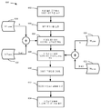
도 5는 도 4에 도시된 제어 로직(400)을 이용하여 디스플레이 상에 이미지를 생성하기 위한 예시적인 프로세스(500)의 흐름도를 도시한다. 프로세스(500)는, 이미지 프레임을 수신하는 단계(스테이지 502), 수신된 이미지 프레임을 XYZ 컬러 공간으로 맵핑하는 단계(스테이지 504), 이미지 프레임을 XYZ 컬러 공간으로부터 적색(R), 녹색(G), 청색(B), 및 백색(W) 컬러 서브필드들로 분해하는 단계(스테이지 506), 이미지 프레임을 디더링하는 단계(스테이지 508), 컬러 서브필드들 각각에 대해 서브프레임들을 생성하는 단계(스테이지 510), 및 서브프레임들을 디스플레이하여 이미지를 출력하는 단계(스테이지 512)를 포함한다. 일부 구현들에서, 프로세스(500)는 채도 보상 로직(408)을 이용하지 않고 이미지들을 디스플레이한다. 채도 보상 로직(408)을 이용하는 프로세스가 도 6에 도시된다.[0080]
FIG. 5 shows a flow diagram of an
[0081]
도 4 및 도 5를 참조하면, 프로세스(500)는 이미지 프레임과 연관된 데이터를 수신하는 입력 로직(402)을 포함한다(스테이지 502). 통상적으로, 이러한 이미지 데이터는 이미지 프레임 내의 각각의 픽셀의 적색, 녹색 및 청색 컴포넌트들에 대한 강도 값들의 스트림으로서 획득된다. 강도 값들은 통상적으로 2진수들로서 수신된다. 수신된 데이터는 RGB 컬러 서브필드들의 입력 세트로서 저장된다. 각각의 컬러 서브필드는, 디스플레이 내의 각각의 픽셀에 대해, 이미지 프레임을 형성하기 위해 그 컬러에 대해 그 픽셀에 의해 송신될 광량을 나타내는 강도 값을 포함한다. 일부 구현들에서, 입력 로직(402) 및/또는 서브필드 유도 로직(404)은 수신된 이미지 데이터(통상적으로 적색, 녹색 및 청색)로 표현된 각각의 프라이머리 컬러에 대한 픽셀 강도 값들을 각각의 서브필드들로 분리함으로써 컴포넌트 컬러 서브필드들의 입력 세트를 유도한다. 일부 구현들에서, 하나 또는 그 초과의 이미지 프리-프로세싱 동작들, 감마 보정 및 디더링은 또한, 컬러 서브필드들의 입력 세트를 유도하기 전 또는 컬러 서브필드들의 입력 세트를 유도하는 과정에서, 입력 로직(402) 및/또는 서브필드 유도 로직(404)에 의해 수행될 수 있다.[0081]
Referring to Figures 4 and 5, the
[0082]
서브필드 유도 로직(404)은 컬러 서브필드들의 입력 세트를 XYZ 컬러 스페이스로 변환한다(스테이지 504). 변환 프로세스를 촉진하기 위해서, 서브필드 유도 로직은, 각각의 입력 컬러 서브필드들의 강도 값들이 LUT로의 인덱스로서 역할을 하는 3차원 LUT를 활용할 수 있다. {R, G, B} 강도 값들의 각각의 트리플렛은 XYZ 컬러 공간에서 대응하는 벡터로 맵핑된다. LUT는 RGB->XYZ LUT(514)로 지칭된다. RGB->XYZ LUT(514)는 제어 로직(400)에 포함된 메모리에 저장될 수 있거나, 또는 이는, 제어 로직(400) 외부의 메모리에 저장될 수 있지만, 제어 로직(400)에 의해 액세스가능할 수 있다. 일부 구현들에서, 서브필드 유도 로직(404)은 이미지 프레임을 인코딩하는데 사용되는 컬러 색 영역과 일치되는 변환 매트릭스를 이용하여 각각의 픽셀에 대한 XYZ 3자극 값들을 개별적으로 계산할 수 있다.[0082]
The
[0083]
서브필드 유도 로직(404)은 XYZ 3자극 컬러 공간의 픽셀 값들을 적색(R), 녹색(G), 청색(B) 및 백색(W) 서브필드(또는 RGBW 서브필드들)(스테이지506)로 변환한다. 서브필드 유도 로직은 다음과 같이 정의되는 분해 매트릭스(M)를 적용한다:[0083]
The

![]()
![]()
![]()
![]()
![]()
![]()
![]()
![]()

과 같다.Respectively.
여기서, f는 분해 매트릭스 M과 원하는 3자극 값 XYZ를 포함하는 몇몇 분해 절차이다.Where f is some decomposition procedure involving the decomposition matrix M and the desired tristimulus value XYZ.
[0084]
일부 구현들에서, 분해 매트릭스를 적용하는 대신에, 서브필드 유도 로직(404)은, 서브필드 유도 로직(404)에 의해 저장되거나 또는 액세스가능한 XYZ->RGBW LUT(516)를 활용한다. XYZ->RGBW LUT(516)는 각각의 XYZ 3자극 값 트리플렛을 RGBW 픽셀 강도 값들의 세트로 맵핑한다.[0084]
In some implementations, instead of applying the decomposition matrix, the
[0085]
일부 구현들에서, 제어 로직(400)은, 멀티-프라이머리 디스플레이 프로세스로 지칭되는 것을 이용하여 이미지들을 디스플레이한다. 멀티-프라이머리 디스플레이 프로세스는 이미지를 형성하기 위해 4개 이상의 프라이머리 컬러들을 활용하고, 프라이머리 컬러들의 XYZ 3자극 값들의 합은 색 영역 백색 포인트의 디스플레이 XYZ 3자극 값들과 같다. 이는, 프라이머리들의 합이 백색 포인트와 일치하지 않는 4개 이상의 프라이머리 컬러들을 활용하는 일부 다른 디스플레이 프로세스들과는 대조적이다. 예를 들어, 적색, 녹색, 청색 및 백색 컬러 서브필드들을 이용하는 일부 디스플레이 프로세스들에서, 적색, 녹색 및 청색 컬러 프라이머리들이 색 영역의 디스플레이 백색 포인트와 합쳐지고, 백색 서브필드를 통해 제공된 휘도가 그 결합된 휘도에 추가된다. 즉, 모든 RGBW 프라이머리들이 최대 강도로 조명되었던 경우, 총 조명은 색 영역 백색 포인트의 2배의 휘도를 가질 것이다. 이로써, 일부 구현들에서, 디스플레이 프라이머리들, 적색, 녹색, 청색 및 백색 각각에 대해 위에서 언급된 XYZ 값들은 디스플레이되는 색 영역의 백색 포인트의 XYZ 3자극 값들을 합산한다.[0085]
In some implementations, the
[0086]
일부 구현들에서, 디스플레이는 각각의 서브필드에 대해 상이한 수의 서브프레임들을 이용하여 이미지를 출력한다(단계 512). 이로써, RGBW 서브필드들 내의 픽셀 강도 값들은, 각각의 서브필드에 대해 서브프레임들의 각각의 할당된 수로 그 값들이 디스플레이될 수 있도록 조정된다. 이러한 조정들은 이미지 품질을 감소시킬 수 있는 양자화 에러들을 도입시킬 수 있다. 서브필드 유도 로직(404)은 그러한 양자화 에러들을 완화시키기 위해 디더링 프로세스를 실행한다(스테이지 508).[0086]
In some implementations, the display outputs an image using a different number of subframes for each subfield (step 512). As such, the pixel intensity values in the RGBW subfields are adjusted such that their values can be displayed with each assigned number of subframes for each subfield. These adjustments may introduce quantization errors that may reduce image quality. The
[0087] 일부 구현들에서, 각각의 RGBW 서브필드는 RGBW 컬러 공간에서 개별적으로 디더링된다. 일부 다른 구현들에서, RGBW 서브필드들은 벡터 에러 확산-기반 디더링 알고리즘에 의해 총괄적으로 프로세싱된다. 일부 구현들에서, 그러한 벡터 에러 확산-기반 디더링은 XYZ 컬러 공간에서 수행된다. 따라서, 일부 구현들에서, 디더링은 XYZ 픽셀 값들을 RGBW 서브필드들로 변환하기 전에 수행된다. 벡터 에러 확산에서, 에러들이 XYZ 공간에서 확산되기 때문에, 임의의 하나의 컬러에 대한 에러들이 픽셀들의 색도 또는 휘도 값들에 대한 직접 조정을 통해 모든 컬러들에 걸쳐 확산될 수 있다. 대조적으로, RGB 또는 RGBW 컬러 공간의 디더링은 동일한 컬러 필드 내의 다른 픽셀들에 걸쳐 컬러의 에러를 확산시킨다. 일부 구현들에서, 디더링(스테이지 508) 및 이미지 프레임을 RGBW 서브필드들로 변환하는 것(스테이지 506)은 통합 프로세스로 결합될 수 있다.[0087] In some implementations, each RGBW subfield is individually dithered in the RGBW color space. In some other implementations, the RGBW subfields are processed collectively by a vector error diffusion-based dithering algorithm. In some implementations, such vector error diffusion-based dithering is performed in the XYZ color space. Thus, in some implementations, dithering is performed before converting XYZ pixel values to RGBW subfields. In vector error diffusion, errors are spread in XYZ space, so that errors for any one color can be spread over all colors through direct adjustment to the chromaticity or luminance values of the pixels. In contrast, dithering in the RGB or RGBW color space spreads color errors over other pixels in the same color field. In some implementations, dithering (stage 508) and converting the image frame to RGBW subfields (stage 506) may be combined into an integration process.
[0088]
도 4 및 도 5를 다시 참조하면, 서브프레임 생성 로직(406)은, 서브프레임들의 세트들을 생성하기 위해서 RGBW 서브필드들을 프로세싱한다(스테이지 510). 각각의 서브프레임은 시분할 그레이 스케일 이미지 출력 시퀀스의 특정 시간 슬롯에 대응한다. 이는, 그 시간 슬롯에 대해 디스플레이에서의 각각의 디스플레이 엘리먼트의 원하는 상태를 포함한다. 각각의 시간 슬롯에서, 디스플레이 엘리먼트는, 다양한 광 투과도를 허용하는 하나 또는 그 초과의 상태들 또는 비투과 상태를 취할 수 있다. 일부 구현들에서, 생성된 서브프레임들은 도 3에 도시된 디스플레이 엘리먼트들의 어레이(310)의 각각의 디스플레이 엘리먼트에 대한 별개의 상태 값을 포함한다.[0088]
Referring back to Figures 4 and 5, the
[0089]
일부 구현들에서, 서브프레임 생성 로직(406)은 서브프레임들을 생성하기 위해 코드 워드 LUT를 이용한다(스테이지 510). 일부 구현들에서, 코드 워드 LUT는, 주어진 픽셀 강도값들을 발생시키는 대응하는 일련의 디스플레이 엘리먼트 상태들을 표시하는 코드 워드들로 지칭되는 일련의 이진 값들을 저장한다. 코드 워드의 각각의 디지트의 값은 디스플레이 엘리먼트 상태(예를 들어, 명 또는 암, 또는 개방 또는 폐쇄)를 표시하고 코드 워드의 디지트의 포지션은 상태에 기여할 가중치를 나타낸다. 일부 구현들에서, 가중치들이 코드 워드의 각각의 디지트에 할당되어, 각각의 디지트에는 선행하는 디지트의 가중치의 2배인 가중치가 할당된다. 일부 다른 구현들에서, 코드 워드의 다수의 디지트들에는 동일한 가중치가 할당될 수 있다. 일부 다른 구현들에서, 각각의 디지트에는 상이한 가중치가 할당되지만, 가중치들은 모두, 고정된 패턴, 디지트 투 디지트에 따라 증가하지 않을 수 있다.[0089]
In some implementations, the
[0090]
서브프레임들의 세트를 생성하기 위해서(스테이지 510), 서브프레임 생성 로직(406)은 컬러 서브필드 내의 모든 픽셀에 대한 코드 워드들을 획득한다. 서브 프레임 생성 로직(406)은 서브필드 내의 픽셀들의 세트에 대한 코드 워드들 내의 각각의 포지션들 각각에서의 디지트들을 서브프레임들로 함께 집성할 수 있다. 예를 들어, 각각의 픽셀에 대한 각각의 코드 워드의 제 1 포지션에 있는 디지트들이 제 1 서브프레임으로 집성된다. 각각의 픽셀에 대한 각각의 코드 워드의 제 2 포지션에 있는 디지트들이 제 2 서브프레임으로 집성되는 식이다. 일단 생성되면, 서브프레임들은 도 3에 도시된 프레임 버퍼(308)에 저장된다.[0090]
To generate a set of subframes (stage 510), the
[0091] 일부 다른 구현들에서, 예를 들어, 하나 또는 그 초과의 부분 투과 상태들을 달성할 수 있는 광 변조기들을 이용하는 구현들에서, 코드 워드 LUT는 베이스-3, 베이스-4, 베이스-10, 또는 일부 다른 베이스 번호 체계를 이용하여 코드 워드들을 저장할 수 있다.[0091] In some other implementations, for example, in implementations that use light modulators capable of achieving one or more partial transmissive states, the codeword LUT may be a base-3, base-4, base-10, The codewords can be stored using the base numbering scheme.
[0092]
(도 4에 도시된) 제어 로직(400)의 출력 로직(410)은, 수신된 이미지 프레임을 디스플레이하기 위해, 생성된 서브프레임들을 출력할 수 있다(스테이지 512). I/F 칩(318)에 대하여 도 3과 관련하여 상술된 것과 유사하게, 출력 로직(410)은 각각의 서브 프레임이 (도 3에 도시된) 디스플레이 엘리먼트들의 어레이(310)에 로딩되게 하고 출력 시퀀스에 따라 조명되게 한다. 일부 구현들에서, 출력 시퀀스가 구성될 수 있고, 사용자 선호들, 디스플레이되는 이미지 데이터의 컨텐츠, 외부 환경적 팩터들 등에 기초하여 변경될 수 있다.[0092]
The
[0093]
(적색, 녹색 또는 청색 LED들보다 더 전력면에서 효율적인 경향이 있는) 백색 LED들과 같은 고 효율 백색 광원에 의해 조명될 수 있는 백색 서브필드를 통해 어떤 량의 이미지 휘도를 디스플레이함으로써, 프로세스(500)는 디스플레이의 에너지 효율을 개선할 수 있다. 프로세스(500)가 서브필드들 각각이 디스플레이되는 것에 대해 하나의 세트의 3자극 값들을 이용한다고 가정하면, 프로세스는 계산 상 효율적이지만, 특정 이미지들을 재생할 경우 이미지 품질이 감소될 수 있다. 일부 구현들에서, 에너지 효율이 또한 저하될 수 있다. 예를 들어, 무시할 수 없는 부분의 이미지 휘도가 백색 서브필드로 푸시된다고 가정하면, 고도로 포화된(saturated) 컬러들을 갖는 이미지들은 워시 아웃(washed out)된 것으로 보일 수 있다.[0093]
By displaying a certain amount of image brightness through a white subfield that can be illuminated by a high efficiency white light source, such as white LEDs (which tend to be more power efficient than red, green or blue LEDs) ) Can improve the energy efficiency of the display. Assuming that the
[0094]
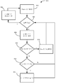
도 6은, 도 4에 도시된 제어 로직(400)을 이용하여 디스플레이 상에 이미지를 생성하기 위한 다른 예시적인 프로세스(600)의 흐름도를 도시한다. 프로세스(600)는, 도 5에 도시된 디스플레이 프로세스(500)로 발생할 수 있는 이미지 품질 문제들을 완화시키기 위해 채도 보상 로직(408)을 활용한다. 보다 구체적으로, 프로세스(600)는, 입력 픽셀 값들이 XYZ 컬러 공간으로 변환되는 방식 및 XYZ 컬러 공간의 픽셀 값이 채도 메트릭(Q)에 기초하여 RGBW 서브필드들 내 픽셀 값들로 변환되는 방식을 조정하며, 이는, 일부 구현들에서, 각각의 이미지 프레임에 대해 결정될 수 있다. 이를 테면, 비디오 이미지들에 대한 일부 구현들에서, 단일 Q 값이 장면의 제 1 이미지 프레임에 기초하여 결정될 수 있고, 장면 변경이 검출될 때까지 후속 이미지 프레임들에 대해 사용될 수 있다. 프로세스(600)는 RGB 컬러 공간에서 이미지 프레임을 수신하는 단계(스테이지 602), 이미지 프레임에 대해, 채도 팩터 Q를 결정하는 단계(스테이지 604), Q에 기초하여 이미지 프레임의 픽셀 값들을 XYZ 컬러 공간에 맵핑하는 단계(스테이지 606), XYZ 컬러 공간의 이미지 프레임을 RGBW 서브필드들로 분해하는 단계(스테이지 608), 프레임 이미지를 디더링하는 단계(스테이지 610), RGBW 서브프레임들을 생성하는 단계(스테이지 612) 및 이미지를 디스플레이하기 위해 서브프레임들을 출력하는 단계(스테이지 614)를 포함한다.[0094]
FIG. 6 shows a flow diagram of another
[0095]
프로세스(600)는, 도 5에 도시된 스테이지(502)와 관련하여 상술된 바와 같은 RGB 픽셀 값들의 스트림의 형태로 RGB 컬러 공간에서 이미지 프레임을 수신하는 단계(스테이지 602)를 포함한다. 스테이지(502)에 대하여 설명된 바와 같이, 스테이지(602)는 픽셀 값들을 사전-프로세싱하는 단계 및 그 결과를 입력 RGB 컬러 서브필드들의 세트에 저장하는 단계를 포함할 수 있다.[0095]
The
[0096]
도 4에 도시된 채도 보상 로직(408)은, 이미지 프레임에 대한 채도 인자 Q를 결정하기 위해서 이미지 프레임을 프로세싱한다(스테이지 604). Q 파라미터는 입력 컬러 색 영역에 대한 출력 컬러 색 영역의 상대적 크기에 대응한다. 다른 방식으로 보면, Q는, 이미지의 휘도가 적색, 녹색 및 청색 서브필드들과 관련하여, 백색 서브필드를 통해 디스플레이에 의해 출력되는 정도를 나타낸다. 일반적으로, Q 값이 증가함에 따라, 디스플레이에 의해 출력되는 컬러 색 영역의 크기가 수축된다. 이 수축은, 서브필드 컬러들의 강도들이 감소되는 한편 그들의 색도들은 고정된 상태로 있는 결과일 수 있다. 예를 들어, 1.0의 Q 값은, 모든 디스플레이 휘도가 백색 서브필드에서 출력되기 때문에, 흑백 이미지에 대응한다. 0.0의 Q 값은, 어떠한 휘도도 백색 서브필드로 전달되지 않는 상태로, 적색, 녹색 및 청색 컬러 필드들에 의해 순수하게 형성된 완전 포화된 컬러 색 영역에 대응한다. 고도로 포화된 컬러들을 포함하는 이미지들은 낮은 Q 값들로 더욱 충실하게 나타내어질 수 있는 반면, 많은 양의 백색 컨텐츠를 갖는 이미지들(예를 들어, 워드 프로세싱 문서들 및 많은 웹 페이지들)이 품질 면에서 지각적으로 상당한 감소없이 높은 Q 값들로 디스플레이되는 반면, 상당한 절전을 획득할 수 있다. 따라서, 대부분 불포화(unsaturated) 컬러들을 포함하는 이미지들의 경우 Q가 크게 선택되는 반면, 고도로 포화된 컬러들을 포함하는 이미지들의 경우 낮은 Q 값들이 선택된다. 일부 구현들에서, Q 값은, 입력 픽셀 값들과 연관된 히스토그램 데이터를 취하고 히스토그램 데이터의 일부 또는 전부를 인덱스로서 Q 값 LUT로 이용함으로써 획득될 수 있다. 일부 구현들에서, 입력 RGB 컬러 서브필드들의 세트는 컬러 에러를 도입하지 않고 이미지 프레임 내의 모든 픽셀로부터 추출될 수 있는 최대 백색 강도 값을 결정하기 위해 분석된다. 일부 이러한 구현들에서, Q는 다음과 같이 계산된다:[0096]
The

여기서, MaxIntensity는 서브필드에서 가능한 최대 강도 값(이를 테면, 8-비트 서브필드에서 255)에 대응한다.Here, MaxIntensity corresponds to the maximum intensity value possible in the subfield (e.g., 255 in the 8-bit subfield).
[0097] 일부 다른 구현들에서, Q는 XYZ 컬러 공간에서 계산될 수 있다. 이러한 구현들에서, Qs는 (원점의) 흑색 및 순수 백색의 XYZ 값들(이를 테면, 0.9502, 1.0, 1.0884의 XYZ 값들)을 연결하는 XYZ 컬러 공간 중심 축에 수직인 공통 평면에 투영된 입력 이미지에 포함된 모든 XYZ 픽셀 값들을 둘러쌀 수 있는 최소 경계(bounding) 육각형의 크기를 식별함으로써 결정될 수 있다. Q는 전체 디스플레이 컬러 색 영역(이를 테면, sRGB, Adobe RGB 컬러 색 영역, 또는 rec.2020 컬러 색 영역과 같은 영역) 캡처로 발생할 수 있는 육각형 및 경계 육각형의 크기의 비와 1.0 간의 차와 동일하게 셋팅된다.[0097] In some other implementations, Q may be computed in the XYZ color space. In such an implementation, Q s is (origin of) the black and XYZ values of pure white input image projected on a common plane perpendicular to the XYZ color space, the central axis linking (such as, 0.9502, 1.0, XYZ values of 1.0884) By identifying the size of the bounding hexagon that can surround all of the X, Y, and Z pixel values contained in the image. Q is equal to the difference between the ratio of the size of the hexagon and boundary hexagons that can occur with capturing the entire display color gamut (such as sRGB, Adobe RGB color gamut, or rec.2020 color gamut) to 1.0 Is set.
[0098] 결정된 Q 값에 기초하여, RGB 컬러 서브필드들의 입력 세트에 저장된 픽셀 값들은 XYZ 컬러 공간으로 맵핑된다(스테이지 606). 상기 나타낸 바와 같이, Q가 증가함에 따라, 적색, 녹색 및 청색 서브필드들을 통해서라기보다 백색 서브필드를 통해 더 많은 이미지 휘도가 출력되기 때문에, 출력 이미지의 색 영역이 감소된다. 이미지 품질을 유지하기 위해서, 즉, 선택된 채도 레벨이 주어지면 적절한 컬러 밸런스를 유지하기 위해서, 픽셀 값들은, 감소된 출력 색 영역에 맞추어진 색 영역 맵핑 알고리즘들을 이용하여 XYZ 컬러 공간으로 변환된다.[0098] Based on the determined Q value, the pixel values stored in the input set of RGB color subfields are mapped to the XYZ color space (stage 606). As indicated above, as Q increases, the color gamut of the output image is reduced because more image brightness is output through the white subfield than through the red, green, and blue subfields. To maintain image quality, i. E. To maintain proper color balance when a selected saturation level is given, pixel values are converted to XYZ color space using gamut mapping algorithms tailored to the reduced output gamut.
[0099]
일부 구현들에서, RGB 값들은, RGB 픽셀 값들의 세트를 Q-의존 컬러 변환 매트릭스와 승산함으로써 XYZ 컬러 공간으로 변환될 수 있다. 일부 다른 구현들에서, 변환 속도를 증가시키기 위해서, 3-차원적 Q-의존 RGB->XYZ LUT들은 {R, G, B} 트리플렛 값들로 인덱싱되는 채도 보상 로직(408)에 의해 저장될 수 있다(또는 이에 의해 접근가능할 수 있다). 대다수의 그러한 LUT들을 저장하는 것은, 일부 구현들에 있어서, 메모리 용량 관점에서 금지될 수 있다. 상당수의 Q-의존 RGB->XYZ LUT들을 저장하는 것과 연관된 메모리 용량 문제들을 개선하기 위해서, 채도 보상 로직(408)은 비교적 작은 수의 Q-의존 RGB->XYZ LUT들을 저장하고, 저장된 LUT들과 연관된 것들 이외의 Q 값들에 대해 LUT들 사이의 보간을 이용할 수 있다.[0099]
In some implementations, the RGB values may be converted to an XYZ color space by multiplying a set of RGB pixel values with a Q-dependent color conversion matrix. In some other implementations, in order to increase the conversion rate, three-dimensional Q-dependent RGB-> XYZ LUTs may be stored by the
[0100]
도 6은 그러한 일 구현을 도시한다. 도 6에 도시된 프로세스(600)는, 2개의 Q-의존 RGB->XYZ LUT들, 즉, Qmin LUT(616) 및 Qmax LUT(618)를 활용한다. Qmin LUT(616)는 제어 로직(400)에 의해 사용되는 Q의 최저 값에 기초하는 RGB->XYZ LUT들이다. Qmin LUT(618)는 제어 로직(400)에 의해 사용되는 Q의 최고 값에 기초하는 RGB->XYZ LUT들이다. 일부 구현들에서, 최소 Q 값은 약 0.01 내지 약 0.2의 범위이고, 최대 Q 값은 약 0.4 내지 약 0.8의 범위이다. 일부 구현들에서, 최대 Q 값은 최대 1.0 범위일 수 있다. 일부 구현들에서, 3개 이상의 Q-의존 RGB->XYZ LUT들)가 더욱 정확한 보간을 위해 활용될 수 있다. 예를 들어, 일부 구현들에서, 프로세스(600)는 0.0, 0.5, 및 1.0의 Q 값들에 대해 RGB->XYZ LUT들을 이용할 수 있다.[0100] FIG. 6 illustrates one such implementation. The
[0101]
보간을 수행하기 위해서, 채도 보상 로직(408)은 다음과 같이 스케일링 팩터 α를 계산할 수 있다 :[0101]
In order to perform the interpolation, the

[0102] XYZ 컬러 공간이 선형이기 때문에, Qmin과 Qmax 사이의 임의의 Q 값들을 갖는 임의의 RGB 입력 픽셀 값에 대한 XYZ 3자극 값들이 다음과 같도록 계산될 수 있다 :[0102] Since the XYZ color space is linear, the XYZ tristimulus values for any RGB input pixel value having any Q values between Q min and Q max can be calculated as follows:
![]()
![]()
여기서, LUT(RGB)는 주어진 RGB 입력 픽셀 값에 대한 LUT의 출력을 나타낸다. 일부 구현들에서, 각각의 픽셀 값에 대해 2개의 룩업 기능들을 수행하는 대신에, 채도 보상 로직(408)은, 주어진 RGB 입력 픽셀 값에 대한 XYZ 3자극 값들을 결정하기 위한 유사한 식에 따라서 Qmin LUT 및 Qmax LUT를 결합하여, 각각의 이미지 프레임에 대해 (또는 이미지 프레임들 사이에서 Q가 변할 때마다) 새로운 RGB->XYZ LUT들을 생성한다. 즉:Here, the LUT (RGB) represents the output of the LUT for a given RGB input pixel value. In some implementations, instead of performing the two lookup functions for each pixel value, the
![]()
![]()
[0103]
이미지 픽셀 값들이 XYZ 3자극 공간에 있으면, 서브필드 유도 로직(404)은 픽셀 값들을 RGBW 컬러 서브필드들의 세트로 분해한다(스테이지 608). 도 5에 도시된 픽셀 분해 스테이지(스테이지 506)와 유사하게, 스테이지(608)에서, 서브필드 유도 로직(404)은 분해 매트릭스를 이용하여 각각의 픽셀 값을 분해한다. 그러나, 스테이지(608)에서, 서브필드 유도 로직(404)은 Q-의존 분해 매트릭스(MQ)를 이용한다. Q-의존 분해 매트릭스(MQ)는 각각의 서브필드와 연관된 XYZ 값들이 선택된 Q의 값에 기초하여 변하는 것을 제외하고, 분해 매트릭스 M과 동일한 형태를 갖는다.[0103] If the image pixel values are in the XYZ triple stimulus space, the
[0104]
일부 구현들에서, 채도 보상 로직(408)은 매우 다양한 Q 값들에 대한 분해 매트릭스들의 세트를 저장하거나 또는 이에 대해 액세스한다. 일부 다른 구현들에서, RGB->XYZ LUT들과 같이, 메모리를 절약하기 위해서, 제어 로직(400)은, 다른 값들에 대한 매트릭스들이 보간을 통해 계산됨에 따라, 더욱 제한된 세트의 분해 매트릭스들(MQ)을 저장하거나 또는 이에 액세스할 수 있다. 예를 들어, 제어 로직은 제 1 분해 매트릭스, MQ -min(620) 및 제 2 분해 매트릭스, MQ -max(622)를 저장하거나 또는 이에 액세스할 수 있다. Qmin과 Qmax 사이의 Q의 값들에 대한 분해 매트릭스들이 다음과 같이 계산될 수 있다.[0104] In some implementations, the
![]()
![]()
[0105]
일부 다른 구현들에서, 스테이지(608)의 Q-종속 분해 매트릭스를 이용하는 대신에, 서브필드 유도 로직(404)은 대신 Q-종속 XYZ->RGBW LUT를 활용한다. Q-의존 RGB->XYZ LUT들과 같이, 서브필드 유도 로직(404)은 제한된 수의 Q-의존 XYZ->RGBW LUT들을 저장하거나 또는 이에 액세스할 수 있다. 그런다음, 서브필드 유도 로직(404)은, Q-특정 RGB->XYZ LUT를 생성하는데 이용되는 유사한 보간 프로세스를 통해 그의 대응하는 Q 값에 기초하여 이미지 프레임에 대한 프레임-특정 XYZ->RGBW LUT를 생성할 수 있다.[0105]
In some other implementations, instead of using the Q-dependent decomposition matrix of
[0106] 일부 다른 구현들에서, LUT는 전혀 이용되지 않을 수 있고, XYZ 대 RGBW 분해는, 모든 Q에 대한 디스플레이 색 영역을 둘러싸는 가상 프라이머리들(R' G' B')을 획득하기 위해서 먼저 XYZ 픽셀 값들에 매트릭스 M'을 승산하여 직접 유도된다. Q=0에 대한 색 영역은 모든 Q>0에 대해 획득된 색 영역을 둘러싸기 때문에, 이 매트릭스 M'은 MQ =0에 대응한다. 그런다음, R, G, B 및 W에 대한 강도 값들이 다음 계산에 의해 획득된다:[0106] In some other implementations, the LUT may not be used at all, and the XYZ to RGBW decomposition may be used to obtain virtual primitives (R 'G' B ') surrounding the display gamut for all Q First, it is directly derived by multiplying the XYZ pixel values by the matrix M '. Since the color gamut for Q = 0 surrounds the gamut obtained for all Q > 0, this matrix M 'corresponds to M Q = 0 . The intensity values for R, G, B and W are then obtained by the following calculation:


[0107]
디스플레이 프로세스는 픽셀 분해 스테이지의 결과들을 디더링하고(스테이지 610), 디더링의 결과들로부터 일 세트의 RGBW 서브프레임들을 생성한다(스테이지 612). 디더링 스테이지(스테이지 610) 및 서브프레임 생성 스테이지(스테이지 612)는 도 5와 관련하여 논의된 프로세스(500)의 대응하는 프로세싱 스테이지들(스테이지들 508 및 510)과 동일할 수 있다.[0107]
The display process dithers the results of the pixel resolution stage (stage 610) and generates a set of RGBW subframes from the results of the dithering (stage 612). The dithering stage (stage 610) and the subframe generation stage (stage 612) may be the same as the corresponding processing stages (
[0108]
생성된 RGBW 서브프레임들은 이미지를 디스플레이하기 위해 출력된다(스테이지 614). 도 5에 도시된 출력 스테이지(512)와는 대조적으로, 서브프레임 출력 스테이지(스테이지 614)는, 이미지 프레임에 대해 선택된 Q의 값에 기초하여 광원들의 강도들을 조정하는 광원 강도 계산 프로세스를 포함한다. 상기 나타내어진 바와 같이, Q의 선택은 디스플레이 색 영역에 대한 변경을 발생시켜, RGB 서브필드들 각각에 대한 광원 강도들이 Q가 증가함에 따라 더 낮게 포화되도록 조정되고, 백색 서브필드에 대한 백색 광원의 강도가 Q가 증가함에 따라 증가된다. 일부 구현들에서, 광원 강도들은 Q의 값에 기초하여 선형적으로 스케일링된다. 예를 들어, Q가 0.5인 경우, 각각의 비-백색 서브필드에 대한 광원 강도 값들에 0.5를 승산한다. 예를 들어, Q가 0.2인 경우, 각각의 비-백색 서브필드에 대한 광원 강도 값들에 0.8을 승산하는 식이다. 일부 구현들에서, 광원 강도 계산은 프로세스(600)에서 더 앞서 수행될 수 있다.[0108]
The generated RGBW subframes are output to display an image (stage 614). In contrast to the
[0109]
도 7은 디스플레이 상에 이미지를 형성하는 예시적인 프로세스(700)의 흐름도를 도시한다. 프로세스(700)는, 제 1 컬러 공간에서 인코딩된 입력 이미지 프레임을 수신하는 단계를 포함하며, 여기서, 입력 이미지 프레임은, 복수의 픽셀들 각각에 대해, 컬러 강도 값들의 세트를 포함한다(스테이지 702). 이러한 프로세싱 스테이지들의 예들은, 도 5 및 도 6에 각각 도시된 스테이지들(502, 602)로서 상술되었다. 프로세스(700)는, 각각의 픽셀과 연관된 컬러 강도 값들을 XYZ 컬러 공간의 대응하는 3자극 값들로 변환하기 위해서, 색 영역 맵핑 프로세스를 수신된 입력 이미지 프레임의 복수의 픽셀들과 연관된 컬러 강도 값들에 적용하는 단계를 포함한다(스테이지 704). 이 프로세싱 스테이지들의 예들은, 도 5 및 도 6에 또한 도시된 스테이지들(504 및606)로서 상술되었다. 프로세스(700)는 적어도 4개의 상이한 컬러들과 연관된 각각의 컬러 서브필드들을 형성하기 위해서 복수의 픽셀들과 연관된 XYZ 3 자극 값들을 분해하는 단계를 더 포함한다(스테이지 706). 각각의 컬러 서브필드는 입력 이미지로부터의 각각의 픽셀들에 대해 대응하는 컬러에 대한 강도 값들을 포함한다. 이 프로세싱 스테이지(706)의 예들은, 도 5 및 도 6에 도시된 스테이지들(506 및 608)과 관련하여 상술되었다. 디스플레이 엘리먼트 상태 정보는 컬러 서브필드들에 기초하여 디스플레이 엘리먼트들의 어레이의 디스플레이 엘리먼트들에 대해 생성된다(스테이지 708). 디스플레이 엘리먼트 상태 정보는, 일부 구현들에서, 서브프레임들을 포함할 수 있다. 서브프레임들을 생성하는 예들은 스테이지들(510 및 612)과 관련하여 논의된다. 프로세스(700)는, 이미지를 형성하기 위해 적어도 4개의 컬러 서브필드와 연관된 디스플레이 엘리먼트 상태 정보를 디스플레이 엘리먼트들의 어레이에 출력하는 단계를 더 포함한다(스테이지 710). 이 프로세싱 스테이지(710)의 예들은, 도 5 및 도 6에 각각 도시된 스테이지들(512 및 614)과 관련하여 상술되었다.[0109]
FIG. 7 shows a flow diagram of an
[0110]
프로세스(700)는 전체 이미지 프레임을 프로세싱하는 것에 대하여 상술되었다. 세그먼트화된 디스플레이들에 대해 유사한 프로세스가 구현될 수 있다. 세그먼트화된 디스플레이에서, 백라이트는 독립적으로 제어되는 세그먼트들의 세트로 분리된다. 이로써, 이미지 프레임은 이미지 프레임 세그먼트들로 나눠질 수 있다. 상이한 세그먼트들에 대응하는 이미지 데이터는 상이한 색도 및/또는 밝기 레벨들의 서브필드들로 나눠질 수 있다. 일부 구현들에서, 세그먼트화된 디스플레이에 대해, 도 7에 도시된 프로세스(700)는, 이미지 프레임의 각각의 세그먼트가 그 자신의 Q 값에 따라 프로세싱되도록 적응된다. 일부 구현들에서, 세그먼트에 대한 Q 값은 임의의 다른 세그먼트의 Q값과 독립적으로 계산되어, 도 6에 도시된 스테이지(604)와 관련하여 상술된 프로세스를 이용하여 그 세그먼트와 연관된 데이터를 별개의 이미지 프레임으로 취급한다. 일부 다른 구현들에서, 세그먼트들에 대한 Q 값들은 2개의 인접한 세그먼트들의 Q 값들이 서로 너무 크게 다르지 않음을 보장하기 위해 총괄적으로 결정됨으로서, 2개의 인접한 세그먼트들 사이에 컬러 채도의 급격한 변화로부터 야기될 수 있는 이미지 아티팩트들이 방지된다. 세그먼트들에 대한 총괄적인 Q 값 결정은 당업자에게 알려진 다양한 제약-기반 최적화 알고리즘들을 이용하여 구현될 수 있다.[0110]
[0111] 상술된 바와 같이 이미지 데이터를 백색 컬러 서브필드로 전송함으로써 이미지들의 형성 시 채도 레벨을 다르게 하는 것을 활용하는 디스플레이들은 배터리 수명을 연장시키도록 돕는 전력 관리 피처들을 구현할 수 있다. 임의의 주어진 이미지에 대해, "무손실" 또는 실질적으로 무손실 Q 값(Qopt)이 존재하는데, 이는 컬러 충실도에 과도하게 영향을 미치지 않으면서 백색 서브필드에 전송될 수 있는 이미지 데이터의 레벨에 대응한다. 일부 구현들에서, Qopt는 출력 이미지에 평균 컬러 에러 양을 도입하는 Q 값에 대응하며, 이 평균 컬러 에러는, 초과할 경우 컬러 에러가 인간의 시각 시스템에 눈에 띄게 되는 임계 컬러 에러와 거의 동일하다(즉, 허용 가능한 낮은 손실이다). 고 효율의 백색 광원에 의해 조명되는 백색 컬러 서브필드를 통해 더 많은 데이터가 제공됨에 따라, 디스플레이의 전력 소모가 감소된다. 극단적으로, 1.0의 Q 값을 갖는 흑색과 백색의 이미지를 출력하는 것은, 비-백색 광원들이 전혀 조명될 필요가 없기 때문에 최대 전력량을 절약한다. 비-백색 서브필드들에 대응하는 서브프레임들을 갖는 디스플레이의 어드레싱을 중지(forgoing)함으로써 전력이 또한 절약될 수 있다.[0111] Displays that utilize different saturation levels in the formation of images by transmitting image data in white color subfields, as described above, may implement power management features that help to extend battery life. For any given image, there is a "lossless" or substantially lossless Q value (Q opt ), which corresponds to the level of image data that can be transmitted in the white subfield without unduly affecting color fidelity . In some implementations, Q opt corresponds to a Q value that introduces an average color error amount to the output image, which exceeds the threshold color error, which, when exceeded, causes the color error to be noticeable in the human visual system (I.e., it is an acceptable low loss). As more data is provided through the white color subfield illuminated by a high efficiency white light source, the power consumption of the display is reduced. Extremely, outputting black and white images with a Q value of 1.0 saves maximum power because the non-white light sources need not be illuminated at all. Power can also be saved by forgoing the addressing of the display with subframes corresponding to the non-white subfields.
[0112]
도 8은 디스플레이의 전력 소모를 감소시키는 예시적인 프로세스(800)의 흐름도를 도시한다. 프로세스(800)에서, 이미지를 디스플레이하기 위해 사용되는 Q의 값을 변화시킴으로써 채도 레벨의 변화를 통해 가능한 전력 절약들은 디스플레이에 대한 비-채도(de-saturation) 기반 타임 아웃 기능을 제공하도록 레버리지될 수 있다. 즉, 디스플레이 디밍 대신, 이후 많은 현재 스마트폰들 및 태블릿 디스플레이들이 수행하도록 구성될 때 비활동 시간 기간이 종료되면, 디스플레이는, 그러한 비활동에 대한 응답으로 (Q 값을 증가시킴으로써) 그의 채도 레벨을 점진적으로 감소시킬 수 있다.[0112]
FIG. 8 shows a flow diagram of an
[0113]
프로세스는 Qopt를 이용하여 이미지들을 디스플레이하는 것을 포함할 수 있다(스테이지 802). 디스플레이 디바이스 또는 디스플레이 디바이스를 포함하는 호스트 디바이스와의 상호작용과 같은 활동이 검출되는 동안(결정 블록 804), 디스플레이 디바이스는 비활동 기간 타이머(스테이지 806)를 리셋하고 Qopt를 이용하여 이미지들을 디스플레이한다(스테이지 802). 어떠한 활동도 검출되지 않으면 (결정 블록 804), 비활동 기간 타이머가 증분된다(스테이지 808). 비활동 기간 타이머가 제 1 임계 값 T1 미만으로 유지되는 경우(결정 블록 810), 프로세스(800)는 Qopt를 이용하여 이미지들을 계속 디스플레이한다(스테이지 802). 비활동 기간 타이머가 T1을 초과하지만, 제 2 임계치 T2 미만으로 유지되면(결정 블록 812), 디스플레이 디바이스는 증가된 Q 값(Qhigh)에서 이미지들을 디스플레이한다(스테이지 814). Qhigh는 Qopt의 배수와 같이 Qopt의 함수일 수 있거나, 또는 고정된 더 높은 Q 값, 이를 테면, 약 0.6 내지 약 0.8의 값일 수 있다. 비활동 기간 타이머가 T1을 초과하면, 디스플레이는 1.0의 Q 값을 이용하여 흑백으로 이미지를 출력한다(스테이지 816). 일부 구현들에서, 디스플레이 디바이스는 1.0의 Q 값을 이용하여 이미지들을 디스플레이하는 것으로 직접 트랜지션한다. 일부 구현들에서, 디스플레이 디바이스는 일련의 프레임들에 걸쳐 Qhigh 값을 이용하는 것에서 1.0 Q 값으로 평탄하게 트랜지션한다. 디스플레이는, 결정 블록(804)에서 활동이 검출될 때까지 1.0의 Q 값을 이용하여 이미지들을 계속 출력한다. 즉, 사용자가 디스플레이를 포함하는 디바이스과 다시 인게이징할 때, 비활동 기간이 리셋될 수 있고(스테이지 806), 디스플레이는 무손실 (또는 허용 가능하게 낮은 손실) Q 값, 즉, Qopt를 이용하여 이미지들을 출력하는 것으로 복귀할 수 있다(스테이지 802).[0113] The process may include displaying images using Q opt (stage 802). While activity such as a display device or interaction with a host device including a display device is detected (decision block 804), the display device resets the inactivity duration timer (stage 806) and displays the images using Q opt (Stage 802). If no activity is detected (decision block 804), the inactivity duration timer is incremented (stage 808). If the inactivity duration timer is maintained below the first threshold T1 (decision block 810), the
[0114]
도 9는 디스플레이의 전력 소모를 감소시키는 제 2 예시적인 프로세스(900)의 흐름도를 도시한다. 프로세스(900)는, 디스플레이가 포함된 호스트 디바이스의 남은 배터리 레벨에 기초하여 이미지를 디스플레이하기 위해 사용되는 Q의 값을 조정한다. 프로세스(900)는 Qopt를 이용하여 이미지들을 디스플레이하는 것을 포함한다(스테이지 902). 프로세스(900)는 호스트 디바이스 배터리 레벨을 체크하고(904), 배터리 레벨을 제 1 임계 값(P1), 이를 테면, 남아있는 배터리 수명의 25%와 비교한다(결정 블록 906). 배터리 레벨이 P1을 초과하는 경우, 디스플레이 디바이스는 Qopt를 이용하여 이미지들을 계속 디스플레이한다(스테이지 902). 배터리 레벨이, 남아있는 배터리 수명의 약 5 %와 같이 P1과 제 2 임계치(P2) 사이에 있는 경우(결정 블록 907), 디스플레이는 잔여 배터리 수명에 관하여 스케일링되는 Q 값(Qscaled로 지칭됨)을 이용하여 이미지들을 디스플레이한다(스테이지 908). 예를 들어, 배터리가 그의 잔여 수명이 약 25 % 내지 약 5 %인 동안, 디스플레이 디바이스는 2개의 Q 값들 사이, 이를 테면, 약 0.25 내지 약 1.0에서 선형 보간(또는 다른 적절한 램핑 기능)을 통해 결정되는 Q 값을 이용하여 이미지들을 출력할 수 있다. 배터리 수명이 P2 미만이면(결정 블록 909), 디스플레이는 1.0의 Q 값을 이용하여 흑백으로 이미지들을 출력한다(스테이지 910). 상기 예에서, 임계 퍼센티지들은 사실상 단지 예시적인 것이고, 다른 구현들에서는 다른 퍼센티지의 임계치들이 사용될 수 있다.[0114] FIG. 9 shows a flow diagram of a second
[0115]
도 10은 원하는 전력 소모 타겟에 부분적으로 기초하여 선택되는 Q 값을 이용하여 이미지들을 출력하는 디스플레이의 예시적인 프로세스(1000)의 흐름도를 도시한다. 일부 전자 디바이스들의 경우, 디바이스에 포함된 디스플레이에 대한 평균 전력 소모 레벨의 식별이 가능하여, 주어진 배터리 수명이 보장될 수 있는 것이 바람직하다. 전력 소모가 디스플레이되는 이미지들의 컨텐츠에 크게 의존하는 디스플레이들의 경우, 정확한 전력 소모 레벨을 제공하는 것이 어려울 수 있다. 도 10에 도시된 프로세스(1000)는, 디스플레이 디바이스로 하여금, 원하는 또는 지정된 전력 소모 타겟을 충족시키기 위해서 이것이 이미지들을 디스플레이하기 위해 (그리고 따라서 그의 전력 소모를 조정하기 위해) 사용하는 Q 값을 조정할 수 있게 한다.[0115]
10 illustrates a flow diagram of an
[0116]
프로세스(1000)는 이미지 프레임을 수신하는 단계(스테이지 1002) 및 Qopt를 결정하는 단계(스테이지 1004)를 포함한다. 디스플레이 디바이스는, 과거 이미지들을 디스플레이하기 위해 이용했던 평균 Q 값인 Qavg 간의 차를, 지정된 전력 소모 타겟에 대응하는 Q 값인 Qtarget과 비교한다. 그 차의 절대 값이 임계치 미만으로 떨어지면(결정 블록 1006), 디스플레이 디바이스는 이미지에 대해 결정된 Qopt 값을 이용하여 이미지를 출력하고(스테이지 1008), Qavg를 업데이트하고(스테이지 1010), 그리고 다음 이미지 프레임을 프로세싱한다. 차의 절대 값이 임계치를 초과하면(결정 블록 1006), 디스플레이 디바이스는, Qavg이 Qtarget보다 큰지를 결정한다(결정 블록 1012). Qavg가 Qtarget보다 작으면, 이미지는 Q의 증가된 값으로 디스플레이되고(스테이지 1014), Qavg가 업데이트되고(스테이지 1010), 다음 이미지 프레임이 수신된다(스테이지 1002). 일부 구현들에서, 증가된 Q 값은, Qavg를 Qtarget에 더 가깝게 이동시키기 시작하기 위해서 Qtarget보다 더 크게 선택된다. 일부 구현들에서, 이미지 충실도의 과도한 저하를 방지하기 위해서 Q의 양이 Qopt를 초과하여 증가되는 것에 대해 제한을 둔다. Qavg가 Qtarget보다 크면, Qopt로 이미지가 디스플레이될 수 있다. 디스플레이는 Qavg를 업데이트하고(스테이지 1010), 수신 시 다음 이미지 프레임을 프로세싱한다(스테이지 1002).[0116]
[0117]
프로세스(1000)의 일부 구현들에서, Qopt는 디스플레이되는 이미지의 컬러 컨텐츠 이외의 데이터에 기초하여 선택될 수 있다. 예를 들어, Qopt는, 선택된 배터리 수명 셋팅과 함께 이미지와 연관된 애플리케이션 또는 컨텐츠 타입에 기초하여 선택될 수 있다. 예를 들어, 일반적으로, 워드 프로세싱 또는 e-리더 애플리케이션에 의해 출력된 이미지들은 이미지 충실도를 크게 저하시키지 않으면서 상대적으로 높은 Q 값들을 이용하여 디스플레이될 수 있는 반면, 사진 또는 비디오 애플리케이션들에 의해 생성된 이미지들은 종종 더 높은 Q 값들로 출력될 경우 이미지 저하를 겪을 수 있다. 배터리 수명 셋팅은, 예를 들어, 디스플레이 디바이스에 의해 또는 디스플레이 디바이스가 포함된 호스트 디바이스에 의해 제공되는 그래피컬 사용자 인터페이스에 의해 조정될 수 있다.[0117] In some implementations of the
[0118] 그러한 구현들에서, 디스플레이 장치는 2차원 LUT를 유지할 수 있다. LUT는, 이미지의 애플리케이션 또는 컨텐츠 타입에 그리고 가능한 배터리 수명 셋팅들에 맞춰진다. LUT는, 각각의 애플리케이션/컨텐츠 타입-배터리 수명 셋팅을 위해 대응하는 Q 값을 저장한다. 이러한 LUT의 예가 표 1로서 아래에 나타내어진다.[0118] In such implementations, the display device may maintain a two-dimensional LUT. The LUT is tailored to the application or content type of the image and to possible battery life settings. The LUT stores the corresponding Q value for each application / content type-battery life setting. An example of such a LUT is shown below as Table 1.

표 1Table 1
[0119] 표 1에 나타내어진 바와 같이, 각각의 애플리케이션에 대한 Q 값들은 일반적으로 원하는 배터리 수명 셋팅이 증가함에 따라 증가한다. 일부 구현들에서, Qtarget은 또한 배터리 수명 셋팅에 기초하여 변할 수 있다. 일부 이러한 구현들에서, 상기 표의 Q 값들은 모든 배터리 수명 셋팅들에 대해 일정할 수 있다.[0119] As shown in Table 1, the Q values for each application generally increase as the desired battery life setting increases. In some implementations, the Q target may also vary based on the battery life setting. In some such implementations, the Q values in the table may be constant for all battery life settings.
[0120]
도 8 내지 도 10에 도시된 프로세스들(800, 900 및 1000)의 일부 구현들에서, 하나 또는 그 초과의 추가 전력 관리 피처들이 구현될 수 있다. 예를 들어, 일부 구현들에서, 디스플레이 장치의 배터리 레벨이 상술된 채도 레벨 변경들 이외에도, 시간에 따라 감소하기 때문에, 디스플레이 장치의 제어 로직(이를 테면, 도 3에 도시된 제어 로직(306))은, 디스플레이 장치가 각각의 이미지 프레임을 출력하기 위해 사용하는 서브 프레임들의 수를 감소시킬 수 있다. 서브프레임들의 수를 감소시키는 것은, 더 이상 디스플레이되지 않을 서브프레임들에 대해 데이터를 디스플레이에 로딩하는데 소비되는 전력의 양을 감소시킴으로써 소모되는 전력의 양을 감소시킨다. 이는 또한, 디스플레이되는 나머지 서브프레임들이 더 낮은 강도로 더 오랫동안 조명되게 하므로, 디스플레이 광원들이 더욱 효율적으로 작동하게 한다.[0120]
In some implementations of the
[0121]
예를 들어, 최대(full) 전력에서, 디스플레이 장치는 적색, 녹색 및 청색 컬러 서브필드들 각각의 경우 4개 내지 8개의 서브프레임들은 이용하고 백색 컬러 서브필드의 경우 3개 내지 5개의 서브프레임들을 이용하여 이미지 프레임을 디스플레이할 수 있다. 배터리 레벨이 감소함에 따라, 디스플레이 장치는, -디스플레이가 도 8 및 도 9의 스테이지들(816 및 910)과 관련하여 논의되는 바와 같이, 모노크롬 모드로 스위칭되지 않는 한, 사용되는 적색, 녹색 및 청색 서브필드들의 수를 3개 내지 5개로 감소시킬 수 있으며, 이 경우, 디스플레이는 어떠한 적색, 녹색 또는 청색 서브프레임들도 전혀 출력하지 않는다. 일부 구현들에서, 동일한 수의 백색 서브프레임들이 배터리 레벨과 무관하게 디스플레이될 수 있다. 일부 구현들에서, 백색 컬러 서브필드를 디스플레이하는데 사용되는 서브프레임들의 수는 Q가 증가함에 따라 증가할 수 있다. 일부 구현들에서, 적색, 녹색 및 청색 서브필드들을 디스플레이하기 위해 사용되는 서브프레임들의 수는 일반적으로, 디스플레이 장치의 배터리 레벨과 무관하게 이미지 프레임을 디스플레이하는데 사용되는 Q의 값에 반비례할 수 있다.[0121]
For example, at full power, the display device uses four to eight subframes for each of the red, green, and blue color subfields and three to five subframes for the white color subfield So that an image frame can be displayed. As the battery level is reduced, the display device may be configured to: Red, Green, and Blue used as long as the display is not switched to the monochrome mode, as discussed with respect to
[0122] 일부 구현들에서, 이미지 프레임을 디스플레이하는데 사용되는 서브프레임의 수가 감소되는 경우, 제어 로직은, 디스플레이로 하여금, 높게 가중된 서브프레임들을 생략하기 전에 더 낮게 가중된 서브프레임들의 디스플레이를 생략하게 한다. 일부 다른 구현들에서, 제어 로직은, 컬러 서브필드를 디스플레이하는데 사용되는 서브프레임들의 수에 따라 컬러 서브필드에 대해 상이한 서브프레임 가중 방식들을 구현할 수 있다. 이외에도, 제어 로직은, 컬러 서브필드를 디스플레이하기 위해 사용되는 서브프레임들 수의 감소로 도입될 수 있는 양자화 에러를 감안하여 그 감소에 대한 응답으로 추가 또는 상이한 디더링 동작들을 구현할 수 있다.[0122] In some implementations, when the number of subframes used to display the image frame is reduced, the control logic causes the display to omit display of the lower weighted subframes before omitting the heavily weighted subframes. In some other implementations, the control logic may implement different subframe weighting schemes for color subfields depending on the number of subframes used to display the color subfields. In addition, the control logic may implement additional or different dithering operations in response to the reduction, taking into account the quantization error that may be introduced as a reduction in the number of subframes used to display the color subfields.
[0123] 디스플레이 장치 배터리 레벨의 감소에 응답하여 더 적은 수의 서브프레임들이 디스플레이되는 일부 구현들에서, 저장될 더 적은 이미지 데이터가 요구됨에 따라, 더 적은 수의 서브프레임들이 사용될 때 경우, 디스플레이 장치의 프레임 버퍼의 부분들을 선택적으로 파워 다운함으로써 추가 절전들이 획득될 수 있다. 디스플레이가 모노크롬 모드에서 동작할 경우, 추가 디스플레이 하드웨어는 추가로 전력을 절약하기 위해 파워 다운될 수 있다. 예를 들어, 적색, 녹색 및 청색 광원들과 연관된 드라이버들 및 로직은, 이들이 주어진 이미지 프레임을 위해 사용되지 않는 경우에는, 파워 다운될 수 있다.[0123] In some implementations where fewer subframes are displayed in response to a decrease in the display device battery level, when fewer subframes are used as fewer image data is required to be stored, Additional power savings can be obtained by selectively powering down portions of the system. When the display operates in monochrome mode, additional display hardware may be powered down to further save power. For example, the drivers and logic associated with the red, green, and blue light sources may be powered down if they are not used for a given image frame.
[0124] 일부 구현들에서, 제어 로직은, 디스플레이 장치의 배터리 레벨에 기초하여 실행되는 이미지 프로세싱 동작들의 복잡성을 조정할 수 있다. 예를 들어, 제어 로직은, 그의 디더링 동작들 동안 고려되는 이미지 프레임의 픽셀들의 수를 변경할 수 있다. 픽셀의 값을 결정하기 위해서, 디더링 알고리즘은, 논의되는 픽셀 주변의 구성가능한 거리 내에서 픽셀들의 값들을 고려한다. 예를 들어, 디더링 알고리즘은 바로 인접한 픽셀들의 값들만 고려할 수 있거나, 또는 2개, 3개, 4개 또는 그 초과의 픽셀들만큼 떨어진 모든 픽셀들의 값들을 고려할 수 있다. 더 많은 수의 픽셀들을 고려하는 디더링 프로세스는, 더 적은 수의 픽셀을 고려하는 프로세스보다 더 많은 프로세서 사이클들을 실행할 필요가 있다. 이로써, 제어 로직은, 배터리 레벨의 감소에 응답하여, 그의 디더링 동작들에서 고려되는 픽셀들의 수를 감소시켜 동작을 완료하는데 필요한 프로세서 사이클들의 수를 감소시킴으로써 전력을 절약하도록 구성될 수 있다.[0124] In some implementations, the control logic may adjust the complexity of image processing operations performed based on the battery level of the display device. For example, the control logic may change the number of pixels of the image frame that are considered during its dithering operations. To determine the value of a pixel, the dithering algorithm considers the values of the pixels within a configurable distance around the pixel being discussed. For example, the dithering algorithm may consider only the values of adjacent pixels immediately, or may take into account the values of all pixels that are two, three, four or more pixels away. A dithering process that considers a larger number of pixels needs to execute more processor cycles than a process that considers fewer pixels. As such, the control logic may be configured to reduce power by reducing the number of processor cycles required to complete the operation, in response to a decrease in battery level, by reducing the number of pixels considered in its dithering operations.
[0125]
상기 전력 관리 기술이 도 8 내지 도 10에 도시된 프로세스들(800, 900 및 1000)과 관련하여 사용하기 위해 상술되었지만, 일부 구현들에서, 디스플레이 제어기는 이러한 프로세스들과 무관하게 이러한 기술들을 활용할 수 있다.[0125]
Although the power management technique has been described above for use in connection with the
[0126]
도 11a 및 도 11b는 복수의 디스플레이 엘리먼트들을 포함하는 예시적인 디스플레이 디바이스(40)의 시스템 블록도들을 도시한다. 디스플레이 디바이스(40)는 예를 들어, 스마트 폰, 셀룰러 또는 모바일 전화일 수 있다. 그러나, 디스플레이 디바이스(40)의 동일한 컴포넌트들 또는 이들의 약간의 변형들이 또한 텔레비전들, 컴퓨터들, 태블릿들, e-리더들, 핸드헬드 디바이스들 및 휴대용 매체 디바이스들과 같은 다양한 타입들의 디스플레이 디바이스들을 예시한다.[0126]
11A and 11B illustrate system block diagrams of an
[0127]
디스플레이 디바이스(40)는, 하우징(41), 디스플레이(30), 안테나(43), 스피커(45), 입력 디바이스(48) 및 마이크로폰(46)을 포함한다. 하우징(41)은 사출 성형 및 진공 성형(vacuum forming)을 포함하는, 다양한 제조 프로세스들 중 임의의 것으로부터 형성될 수 있다. 추가로, 하우징(41)은 플라스틱, 금속, 유리, 고무 및 세라믹 또는 이들의 결합을 포함하는(그러나 이들로 제한되지 않음) 다양한 물질들 중 임의의 것으로 이루어질 수 있다. 하우징(41)은 상이한 컬러의 다른 제거 가능한 부분들과 상호교환될 수 있거나, 상이한 로고들, 사진들 또는 심볼들을 포함하는 제거 가능한 부분들(도시되지 않음)을 포함할 수 있다.[0127]
The
[0128]
디스플레이(30)는 본원에 설명된 바와 같은, 쌍안정형(bi-stable) 또는 아날로그 디스플레이를 포함하는 다양한 디스플레이들 중 임의의 것일 수 있다. 디스플레이(30)는 또한, 플라즈마, EL(electroluminescent) 디스플레이들, OLED, STN(super twisted nematic) 디스플레이, LCD 또는 TFT(thin-film transistors) LCD와 같은 평판-패널 디스플레이 또는 CRT(cathode ray tube) 또는 다른 튜브 디바이스와 같은 비-평판 패널 디스플레이를 포함할 수 있다. 또한, 디스플레이(30)는 본원에서 설명된 바와 같이, 기계적 광 변조기-기반 디스플레이를 포함할 수 있다.[0128]
[0129]
디스플레이 디바이스(40)의 컴포넌트들은 도 11b에 개략적으로 예시된다. 디스플레이 디바이스(40)는 하우징(41)을 포함하며, 적어도 부분적으로 둘러싸인 추가적인 컴포넌트들을 내부에 포함할 수 있다. 예를 들어, 디스플레이 디바이스(40)는 트랜시버(47)에 커플링될 수 있는 안테나(43)를 포함하는 네트워크 인터페이스(27)를 포함한다. 네트워크 인터페이스(27)는 디스플레이 디바이스(40) 상에 디스플레이될 수 있는 이미지 데이터에 대한 소스일 수 있다. 따라서, 네트워크 인터페이스(27)는 이미지 소스 모듈의 일 예이지만, 프로세서(21) 및 입력 디바이스(48)는 또한 이미지 소스 모듈로서의 역할을 할 수 있다. 트랜시버(47)는 프로세서(21)에 연결되며, 프로세서(21)는 컨디셔닝 하드웨어(52)에 연결된다. 컨디셔닝 하드웨어(52)는 (필터를 적용하거나 아니면 신호를 조작하는 것과 같이) 신호를 컨디셔닝하도록 구성될 수 있다. 컨디셔닝 하드웨어(52)는 스피커(45) 및 마이크로폰(46)에 연결될 수 있다. 프로세서(21)는 또한 입력 디바이스(48) 및 드라이버 제어기(29)에 연결될 수 있다. 드라이버 제어기(29)는 프레임 버퍼(28) 및 어레이 드라이버(22)에 커플링될 수 있으며, 이는 차례로 디스플레이 어레이(30)에 커플링될 수 있다. 도 11a에 구체적으로 도시되지 않는 엘리먼트들을 포함하는, 디스플레이 디바이스(40)에서의 하나 또는 그 초과의 엘리먼트들은 메모리 디바이스로서 기능하고 프로세서(21)와 통신 가능할 수 있다. 일부 구현들에서, 전원(50)은 특정 디스플레이 디바이스(40) 설계에서의 실질적으로 모든 컴포넌트들에 파워를 제공할 수 있다.[0129]
The components of the
[0130]
네트워크 인터페이스(27)는 디스플레이 디바이스(40)가 네트워크를 통해 하나 또는 그 초과의 디바이스들과 통신할 수 있도록 안테나(43) 및 트랜시버(47)를 포함한다. 네트워크 인터페이스(27)는 또한 예를 들어, 프로세서(21)의 데이터 프로세싱 요건들을 완화하는 일부 프로세싱 능력들을 가질 수 있다. 안테나(43)는 신호들을 송신하고 수신할 수 있다. 일부 구현들에서, 안테나(43)는 IEEE 16.11 표준 중 임의의 것 또는 임의의 IEEE 802.11 표준에 따라 RF 신호를 송신 및 수신한다. 일부 다른 구현들에서, 안테나(43)는 블루투스® 표준에 따라 RF 신호들을 송신하고 수신한다. 셀룰러 전화의 경우에, 안테나(43)는 CDMA(code division multiple access), FDMA(frequency division multiple access), TDMA(time division multiple access), GSM(Global System for Mobile communications), GPRS(GSM/General Packet Radio Service), EDGE(Enhanced Data GSM Environment), TETRA(Terrestrial Trunked Radio), W-CDMA(Wideband-CDMA), EV-DO(Evolution Data Optimized), 1xEV-DO, EV-DO Rev A, EV-DO Rev B, HSPA(High Speed Packet Access), HSDPA(High Speed Downlink Packet Access), HSUPA(High Speed Uplink Packet Access), HSPA+(Evolved High Speed Packet Access), LTE(Long Term Evolution ), AMPS, 또는 3G, 4G 또는 5G, 또는 이들의 추가 구현들, 기술을 활용하는 시스템과 같은 무선 네트워크 내에서 통신하기 위해 이용되는 다른 알려진 신호들을 수신하도록 설계될 수 있다. 트랜시버(47)는 안테나(43)로부터 수신되는 신호들이 프로세서(21)에 의해 수신되고 추가로 조작될 수 있도록 이들을 사전-프로세싱할 수 있다. 트랜시버(47)는 또한, 신호들이 안테나(43)를 통해 디스플레이 디바이스(40)로부터 송신될 수 있도록, 프로세서(21)로부터 수신되는 신호들을 프로세싱할 수 있다.[0130]
The network interface 27 includes an
[0131]
일부 구현들에서, 트랜시버(47)는 수신기로 대체될 수 있다. 추가로, 일부 구현들에서, 네트워크 인터페이스(27)는 프로세서(21)에 송신될 이미지 데이터를 저장 또는 발생시킬 수 있는 이미지 소스로 대체될 수 있다. 프로세서(21)는 디스플레이 디바이스(40)의 전체 동작을 제어할 수 있다. 프로세서(21)는 네트워크 인터페이스(27) 또는 이미지 소스로부터 압축된 이미지 데이터와 같은 데이터를 수신하며, 이 데이터를 원시(raw) 이미지 데이터로 또는 원시 이미지 데이터로 쉽게 프로세싱될 수 있는 포맷으로 프로세싱한다. 프로세서(21)는 프로세싱된 데이터를, 저장을 위해 프레임 버퍼(28) 또는 드라이버 제어기(29)에 전송할 수 있다. 원시 데이터는 통상적으로 이미지 내의 각 위치에서 이미지 특성들을 식별하는 정보를 지칭한다. 예를 들어, 그와 같은 이미지 특징들은 컬러, 채도 및 그레이-스케일 레벨을 포함할 수 있다.[0131]
In some implementations, the transceiver 47 may be replaced with a receiver. In addition, in some implementations, the network interface 27 may be replaced with an image source capable of storing or generating image data to be transmitted to the
[0132]
프로세서(21)는 디스플레이 디바이스(40)의 동작을 제어하기 위해 마이크로제어기, CPU 또는 로직 유닛을 포함할 수 있다. 컨디셔닝 하드웨어(52)는 신호들을 스피커(45)에 전송하고 마이크로폰(46)부터 신호들을 수신하기 위해 증폭기들 및 필터들을 포함할 수 있다. 컨디셔닝 하드웨어(52)는 디스플레이 디바이스(40) 내의 이산 컴포넌트들일 수 있거나, 프로세서(21) 또는 다른 컴포넌트들 내에 포함될 수 있다.[0132]
The
[0133]
드라이버 제어기(29)는 직접 프로세서(21)로부터 또는 프레임 버퍼(28)로부터 프로세서(21)에 의해 발생되는 원시 이미지 데이터를 취할 수 있으며 어레이 드라이버(22)로의 고속 전송을 위해 적절하게 원시 이미지 데이터를 재포맷할 수 있다. 일부 구현들에서, 드라이버 제어기(29)는 디스플레이 어레이(30)에 걸친 스캐닝을 위해 적합한 시간 순서를 갖도록 원시 이미지 데이터를 래스터-형(raster-like) 포맷을 갖는 데이터 흐름으로 재포맷할 수 있다. 그 후에 드라이버 제어기(29)는 포맷된 정보를 어레이 드라이버(22)에 전송한다. 드라이버 제어기(29)가 종종 자립형 IC(Integrated Circuit)로서 시스템 프로세서(21)와 관련되더라도, 그와 같은 제어기들은 많은 방식들로 구현될 수 있다. 예를 들어, 제어기들은 하드웨어로서 프로세서(21)에 임베딩될 수 있고, 소프트웨어로서 프로세서(21)에 임베딩될 수 있거나, 어레이 드라이버(22)로 하드웨어에 완전히 통합될 수 있다.[0133]
The driver controller 29 may take raw image data generated by the
[0134]
어레이 드라이버(22)는 포맷된 정보를 드라이버 제어기(29)로부터 수신할 수 있으며 디스플레이 엘리먼트들의 디스플레이의 x-y 매트릭스로부터 발생하는 수백 및 때때로 수천(또는 그 이상)개의 도선들에 초당 수회(many times) 인가되는 병렬 세트의 파형들로 비디오 데이터를 재포맷할 수 있다. 일부 구현들에서, 어레이 드라이버(22) 및 디스플레이 어레이(30)는 디스플레이 모듈의 일부이다. 일부 구현들에서, 드라이버 제어기(29), 어레이 드라이버(22) 및 디스플레이 어레이(30)는 디스플레이 모듈의 일부이다.[0134]
The
[0135]
일부 구현들에서, 드라이버 제어기(29), 어레이 드라이버(22) 및 디스플레이 어레이(30)는 본원에 설명된 타입들 중 임의의 것의 디스플레이들에 대해 적절하다. 예를 들어, 드라이버 제어기(29)는 종래의 디스플레이 제어기 또는 쌍안정 디스플레이 제어기(예컨대, 기계적 광 변조기 디스플레이 엘리먼트 제어기)일 수 있다. 부가적으로, 어레이 드라이버(22)는 종래의 드라이버 또는 쌍안정 디스플레이 드라이버(예컨대, 기계적 광 변조기 디스플레이 엘리먼트 제어기)일 수 있다. 또한, 디스플레이 어레이(30)는 종래의 디스플레이 어레이 또는 쌍안정 디스플레이 어레이(예컨대, 기계적 광 변조기 디스플레이 엘리먼트들의 어레이를 포함하는 디스플레이)일 수 있다. 일부 구현들에서, 드라이버 제어기(29)는 어레이 드라이버(22)에 통합될 수 있다. 그와 같은 구현은 고집적 시스템들, 예를 들어, 이동 전화들, 휴대용-전자 디바이스들, 시계들 또는 소형-영역 디스플레이들에서 유용할 수 있다.[0135]
In some implementations, the driver controller 29, the
[0136]
일부 구현들에서, 입력 디바이스(48)는 예를 들어, 사용자로 하여금 디스플레이 디바이스(40)의 동작을 제어하게 하도록 구성될 수 있다. 입력 디바이스(48)는 QWERTY 키보드 또는 전화 키패드와 같은 키패드, 버튼, 스위치, 로커(rocker), 터치-감지 스크린, 디스플레이 어레이(30)에 통합된 터치-감지 스크린 또는 압력- 또는 열-감지 멤브레인(membrane)을 포함할 수 있다. 마이크로폰(46)은 디스플레이 디바이스(40)에 대한 입력 디바이스로서 구성될 수 있다. 일부 구현들에서, 마이크로폰(46)을 통한 음성 커맨드들은 디스플레이 디바이스(40)의 동작들을 제어하기 위해 이용될 수 있다. 추가로, 일부 구현들에서, 음성 명령들은 디스플레이 파라미터들 및 셋팅들을 제어하는데 사용될 수 있다.[0136]
In some implementations, the
[0137]
전원(50)은 다양한 에너지 저장 디바이스들을 포함할 수 있다. 예를 들어, 전원(50)은 니켈-카드뮴 배터리 또는 리튬-이온 배터리와 같은 충전용 배터리일 수 있다. 충전용 배터리를 이용하는 구현들에서, 충전용 배터리는 예를 들어, 벽 소켓 또는 광전지 디바이스 또는 어레이로부터 발생하는 파워를 이용하여 충전할 수 있다. 대안적으로, 충전용 배터리는 무선으로 충전 가능할 수 있다. 전원(50)은 또한, 재생 가능한 에너지 소스, 커패시터 또는 플라스틱 솔라 셀 또는 솔라-셀 페인트를 포함하는 솔라 셀일 수 있다. 전원(50)은 또한 벽 콘센트로부터 전력을 수신하도록 구성될 수 있다.[0137]
The
[0138]
일부 구현들에서, 제어 프로그램능력은 전자 디스플레이 시스템에서의 여러 장소들에 위치될 수 있는 드라이버 제어기(29)에 존재한다. 일부 다른 구현들에서, 제어 프로그램능력은 어레이 드라이버(22)에 존재한다. 위에서 설명된 최적화는 임의의 수의 하드웨어 및/또는 소프트웨어 컴포넌트들에서 그리고 다양한 구성들에서 구현될 수 있다.[0138]
In some implementations, the control program capability resides in the driver controller 29, which may be located at various locations in the electronic display system. In some other implementations, the control program capability resides in the
[0139] 본원에서 이용되는 바와 같이, 아이템들의 리스트 중 "적어도 하나(at least one of)"를 지칭하는 문구는 단일의 부재들을 포함하는 이들 아이템들의 임의의 조합을 지칭한다. 예로서, "a, b 또는 c 중 적어도 하나"는 a, b, c, a-b, a-c, b-c, 및 a-b-c를 커버하도록 의도된다.[0139] As used herein, the phrase "at least one of the list of items " refers to any combination of these items, including single items. By way of example, "at least one of a, b, or c" is intended to cover a, b, c, a-b, a-c, b-c, and a-b-c.
[0140] 본원에 개시된 구현들과 관련하여 설명된 다양한 예시적인 로직들, 로직 블록, 모듈, 회로, 및 알고리즘 프로세스들은, 전자 하드웨어, 컴퓨터 소프트웨어, 또는 이 둘의 조합으로 구현될 수 있다. 하드웨어 및 소프트웨어의 상호 호환성은 기능성의 관점에서 대체로 설명되었고, 상기 설명된 다양한 예시적인 컴포넌트들, 블록들, 모듈들, 회로들 및 프로세스들에서 예시되었다. 이러한 기능이 하드웨어 또는 소프트웨어로 구현되는지 여부는 전체 시스템에 부과된 특정 애플리케이션 및 설계 제약들에 의존한다.[0140] The various illustrative logics, logic blocks, modules, circuits, and algorithm processes described in connection with the implementations disclosed herein may be implemented as electronic hardware, computer software, or combinations of both. Hardware and software interoperability has been described generally in terms of functionality and has been illustrated in the various exemplary components, blocks, modules, circuits, and processes described above. Whether such functionality is implemented in hardware or software depends upon the particular application and design constraints imposed on the overall system.
[0141] 본원에 개시된 양상들과 관련하여 설명된 다양한 예시적인 로직, 로직 블록, 모듈, 및 회로를 구현하는데 사용되는 하드웨어 및 데이터 프로세싱 장치는, 범용 단일- 또는 다중-칩 프로세서, 디지털 신호 프로세서(DSP), 주문형 집적 회로(ASIC), 필드 프로그래밍 가능 게이트 어레이(FPGA), 또는 기타 프로그래밍 가능 로직 디바이스, 이산 게이트 또는 트랜지스터 로직, 이산 하드웨어 컴포넌트, 또는 본원에 설명된 기능을 수행하도록 설계된 이들의 임의의 결합으로 구현 또는 수행될 수 있다. 범용 프로세서는 마이크로프로세서, 또는, 임의의 종래의 프로세서, 제어기, 마이크로제어기, 또는 상태 머신일 수 있다. 프로세서는 또한 컴퓨팅 장치들의 조합, 예를 들어, DSP와 마이크로 프로세서의 조합, 복수의 마이크로 프로세서들, DSP 코어와 결합 된 하나 또는 그 초과의 마이크로 프로세서들, 또는 임의의 다른 이러한 구성으로 구현될 수 있다. 일부 구현들에서, 특정 프로세스들 및 방법들은 주어진 기능에 특정한 회로에 의해 수행될 수 있다.[0141] The hardware and data processing apparatus used to implement the various illustrative logic, logic blocks, modules, and circuits described in connection with the aspects disclosed herein may be implemented or performed with a general purpose single- or multi-chip processor, a digital signal processor (DSP) (ASIC), a field programmable gate array (FPGA), or other programmable logic device, discrete gate or transistor logic, discrete hardware components, or any combination thereof designed to perform the functions described herein Or may be performed. A general purpose processor may be a microprocessor, or any conventional processor, controller, microcontroller, or state machine. The processor may also be implemented as a combination of computing devices, e.g., a combination of a DSP and a microprocessor, a plurality of microprocessors, one or more microprocessors in conjunction with a DSP core, or any other such configuration . In some implementations, the specific processes and methods may be performed by circuitry specific to a given function.
[0142] 하나 또는 그 초과의 양상들에서, 설명된 기능들은 본 명세서에 개시된 구조 및 그의 구조적 등가물들을 비롯해서, 디지털 전자 회로, 컴퓨터 소프트웨어, 펌웨어, 하드웨어 또는 이들의 임의의 결합으로 구현될 수 있다. 본 명세서에 설명된 청구 대상의 구현들은 또한 데이터 프로세싱 장치의 동작을 제어하거나 또는 장치에 의한 실행을 위해 컴퓨터 저장 매체들 상에 인코딩된 하나 또는 그 초과의 컴퓨터 프로그램들 즉, 컴퓨터 프로그램 명령의 하나 또는 그 초과의 모듈로서 구현될 수 있다.[0142] In one or more aspects, the functions described may be implemented in digital electronic circuitry, computer software, firmware, hardware, or any combination thereof, including the structures disclosed herein and structural equivalents thereof. Implementations of the claimed subject matter described herein may also be embodied in one or more computer programs encoded on computer storage media for controlling the operation of the data processing apparatus or for execution by the apparatus, It can be implemented as a module of more than that.
[0143] 소프트웨어로 구현되는 경우, 기능들은 하나 또는 그 초과의 명령들 또는 코드로서 컴퓨터 판독가능 매체 상에 저장되거나 또는 이로서 송신될 수 있다. 본원에 개시된 방법 또는 알고리즘의 프로세스들은 컴퓨터 판독 가능 매체에 상주할 수있는 프로세서 실행 가능한 소프트웨어 모듈로 구현될 수 있다. 컴퓨터 판독 가능 매체는 한 장소에서 다른 장소로 컴퓨터 프로그램을 전송할 수 있게 되는 임의의 매체를 포함하는 통신 매체 및 컴퓨터 저장 매체 둘 모두를 포함한다. 저장 매체는 컴퓨터에 의해 액세스될 수 있는 임의의 이용가능한 매체일 수 있다. 제한적이지 않은 예로서, 이러한 컴퓨터-판독가능 매체는, RAM, ROM, EEPROM, CD-ROM 또는 다른 광학 디스크 저장소, 자기 디스크 저장소 또는 다른 자기 저장 디바이스, 또는 명령 또는 데이터 구조의 형태로 원하는 프로그램 코드를 저장하는데 사용될 수 있고 컴퓨터에 의해 액세스 될 수 있는 임의의 다른 매체를 포함할 수 있다. 또한, 임의의 접속이 컴퓨터 판독 가능 매체로 적절히 지칭될 수 있다. 여기서 사용되는 디스크(disk 및 disc)는 CD(compact disc), 레이저 디스크(disc), 광 디스크(disc), DVD(digital versatile disc), 플로피 디스크(disk) 및 블루-레이 디스크(disc)를 포함하며, 여기서 디스크(disk)들은 대개 데이터를 자기적으로 재생하지만, 디스크(disc)들은 레이저들을 이용하여 광학적으로 데이터를 재생한다. 상기의 결합들이 또한 컴퓨터 판독가능 매체들의 범위 내에 포함되어야 한다. 추가로, 방법 또는 알고리즘의 동작들은, 머신 판독가능 매체 및 컴퓨터-판독가능 매체 상의 코드들 및 명령들 중 하나 또는 임의의 조합 또는 세트로서 존재할 수 있으며, 이는 컴퓨터 프로그램 제품에 포함될 수 있다.[0143] When implemented in software, the functions may be stored on or transmitted by one or more instructions or code on a computer readable medium. The processes of the methods or algorithms disclosed herein may be implemented as processor-executable software modules that may reside on a computer-readable medium. Computer-readable media includes both communication media and computer storage media, including any medium that is capable of transferring computer programs from one place to another. The storage medium may be any available media that can be accessed by a computer. By way of example, and not limitation, such computer-readable media can comprise any computer-readable medium, such as RAM, ROM, EEPROM, CD-ROM or other optical disk storage, magnetic disk storage or other magnetic storage devices, And any other medium that can be used to store and be accessed by a computer. Also, any connection may be properly referred to as a computer-readable medium. The disks and discs used herein include a CD (compact disc), a laser disc, an optical disc, a digital versatile disc (DVD), a floppy disc, and a Blu-ray disc Wherein discs usually reproduce data magnetically, but discs reproduce data optically using lasers. Such combinations should also be included within the scope of computer readable media. Additionally, the operations of the method or algorithm may be in the form of one or any combination or set of codes and instructions on a machine-readable medium and a computer-readable medium, which may be included in a computer program product.
[0144] 본 개시물에 설명된 구현들에 대한 다양한 수정들은 당업자들에게 용이하게 명백할 것이고, 여기에서 정의된 일반적인 원리들은 본 개시물의 사상 또는 범위를 벗어나지 않고 다른 구현들에 적용될 수 있다. 따라서, 본 청구범위는 본 명세서에 제시된 구현들로 한정되도록 의도되는 것이 아니라, 본 명세서에 개시된 개시내용, 원리들 및 신규한 특징들과 일치하는 최광의 범위와 조화될 것이다.[0144] Various modifications to the implementations described in this disclosure will be readily apparent to those skilled in the art, and the generic principles defined herein may be applied to other implementations without departing from the spirit or scope of the disclosure. Accordingly, it is not intended that the scope of the claims be limited to the implementations set forth herein, but is to be accorded the widest scope consistent with the teachings, principles and novel features disclosed herein.
[0145] 부가적으로, 당업자는, 용어들 "상부" 및 "하부" 가 때때로 도면들의 설명을 용이하게 하기 위해 이용되며, 적절하게 배향된 페이지 상의 도면의 배향에 대응하는 상대적인 포지션들을 표시하고, 구현된 바와 같은 임의의 디바이스의 적절한 배향을 반영하지 않을 수 있다는 것을 용이하게 인식할 것이다.[0145] Additionally, those skilled in the art will appreciate that the terms "upper" and "lower" are sometimes used to facilitate the description of the drawings, indicate relative positions corresponding to the orientation of the drawing on properly orientated pages, But may not reflect the proper orientation of any such device.
[0146] 개별적인 구현들의 맥락에서 이 명세서에서 설명되는 특정 특징들은 또한 결합되어 단일 구현으로 구현될 수 있다. 반대로, 단일 구현의 맥락에서 설명된 다양한 특징들은 또한 개별적으로 다수의 구현들로 또는 임의의 적합한 하위 조합으로 구현될 수 있다. 또한, 특징들이 특정 조합들에서 작용하고 심지어 그처럼 초기에 청구된 대로 위에서 설명될 수 있지만, 청구된 조합으로부터의 하나 또는 그 초과의 특징은 어떤 경우에는 조합으로부터 삭제될 수 있고, 청구된 조합은 하위 조합 또는 하위 조합의 변형으로 지향될 수 있다.[0146] Certain features described herein in the context of separate implementations may also be combined and implemented in a single implementation. Conversely, various features described in the context of a single implementation may also be implemented individually in multiple implementations or in any suitable subcombination. In addition, one or more features from the claimed combination may in some cases be deleted from the combination, and the claimed combination may be deleted from the combination, even though the features may function in certain combinations and may even be described above as initially claimed. Combinations or sub-combinations thereof.
[0147] 유사하게, 동작들이 도면들에서 특정한 순서로 도시되지만, 바람직한 결과들을 달성하기 위해서, 이는, 이러한 동작들이 도시된 특정한 순서 또는 순차적 순서로 수행되거나 또는 모든 예시된 동작들이 수행될 필요는 없는 것으로 이해될 것이다. 추가로, 도면들은 하나 또는 그 초과의 예시적인 프로세스들을 흐름도의 형태로 개략적으로 도시할 수 있다. 그러나, 도시되지 않은 다른 연산들은, 개략적으로 도시되는 예시적인 프로세스들에 포함될 수 있다. 예를 들어, 하나 또는 그 초과의 추가 동작들이, 예시되는 동작들 중 임의의 동작 전, 후, 동시 또는 사이에서 수행될 수 있다. 특정한 환경들에서, 멀티태스킹 및 병렬적 프로세싱이 유리할 수 있다. 아울러, 앞서 설명된 구현들에서 다양한 시스템 컴포넌트들의 분리는 모든 구현들에서 이러한 분리를 요구하는 것으로 이해되어서는 안 되며, 설명된 프로그램 컴포넌트들 및 시스템들이 일반적으로 단일 소프트웨어 물건으로 함께 통합되거나 또는 다수의 소프트웨어 물건들로 패키징될 수 있음이 이해되어야 한다. 추가로, 다른 구현들은 다음 청구항들의 범위 내에 있다. 일부 경우들에서, 청구항들에서 인용되는 동작들은 상이한 순서로 수행될 수 있으며, 여전히 바람직한 결과들을 달성할 수 있다.[0147] Similarly, although operations are shown in a particular order in the figures, in order to achieve the desired results, it should be understood that these operations may be performed in the specific order or sequential order shown, or that all illustrated acts need not be performed will be. In addition, the drawings may schematically depict one or more exemplary processes in the form of a flowchart. However, other operations not shown may be included in the exemplary processes schematically depicted. For example, one or more additional operations may be performed before, after, simultaneously, or between any of the illustrated operations. In certain circumstances, multitasking and parallel processing may be advantageous. In addition, the separation of various system components in the above-described implementations should not be understood as requiring such separation in all implementations, and the described program components and systems may be generally integrated together into a single software article, It should be understood that they can be packaged into software objects. In addition, other implementations are within the scope of the following claims. In some cases, the operations recited in the claims may be performed in a different order and still achieve the desired results.
Claims (28)
디스플레이 엘리먼트들의 어레이;
제어 로직을 포함하며,
상기 제어 로직은,
입력 이미지 프레임을 수신하고 ―상기 입력 이미지 프레임은, 복수의 픽셀들 각각에 대해, 컬러 파라미터 값들의 제 1 세트를 포함함―;
상기 컬러 파라미터 값들의 제 1 세트를 컬러 파라미터 값들의 제 2 세트로 맵핑하기 위해 픽셀과 연관된 상기 컬러 파라미터 값들의 제 1 세트에 컨텐츠 적응형 색 영역(gamut) 맵핑 프로세스를 적용하고 ―상기 컨텐츠 적응형 색 영역 맵핑 프로세스는 적어도 부분적으로 상기 이미지 프레임의 컨텐츠에 기초함―; 그리고
적어도 4개의 상이한 컬러들과 연관된 각각의 컬러 서브필드들에서 픽셀 강도 값들을 획득하기 위해서 상기 픽셀과 연관된 상기 컬러 파라미터 값들의 제 2 세트를 분해하고;
상기 컬러 서브필드들에 기초하여 상기 디스플레이 엘리먼트들에 대한 디스플레이 엘리먼트 상태 정보를 생성하고; 그리고
적어도 4개의 컬러 서브필드들과 연관된 디스플레이 엘리먼트 상태 정보를 상기 디스플레이 엘리먼트들의 어레이에 출력하도록 구성되는, 장치.As an apparatus,
An array of display elements;
Control logic,
The control logic comprises:
The method comprising: receiving an input image frame, the input image frame comprising, for each of a plurality of pixels, a first set of color parameter values;
Applying a content adaptive gamut mapping process to a first set of color parameter values associated with a pixel to map a first set of color parameter values to a second set of color parameter values, Wherein the gamut mapping process is based at least in part on the content of the image frame; And
Decompose a second set of color parameter values associated with the pixel to obtain pixel intensity values in respective color subfields associated with at least four different colors;
Generate display element state information for the display elements based on the color sub-fields; And
And to output to the array of display elements display element state information associated with at least four color sub-fields.
상기 컬러 파라미터 값들의 제 1 세트는 적색, 녹색 및 청색 픽셀 강도 값들을 포함하고, 상기 컬러 파라미터 값들의 제 2 세트는 XYZ 3자극 값들을 포함하는, 장치.The method according to claim 1,
Wherein the first set of color parameter values includes red, green, and blue pixel intensity values, and wherein the second set of color parameter values comprises X, Y, and Z three stimulus values.
상기 제어 로직은 추가로,
상기 이미지에 대한 채도 레벨 파라미터를 결정하고 그리고 상기 입력 이미지 프레임의 결정된 컬러 채도 파라미터에 기초하여 상기 색 영역 맵핑 프로세스를 적응시키도록 구성되는, 장치.The method according to claim 1,
The control logic further comprises:
Determine a saturation level parameter for the image and adapt the gamut mapping process based on a determined color saturation parameter of the input image frame.
상기 제어 로직은 추가로, 이미지 채도 레벨-의존 색 영역 맵핑 룩업 테이블을 생성함으로써 상기 색 영역 맵핑 프로세스를 적응시키도록 구성되는, 장치.The method of claim 3,
Wherein the control logic is further configured to adapt the gamut mapping process by creating an image saturation level-dependent color gamut mapping look-up table.
상기 제어 로직은 추가로, 상기 결정된 이미지 채도 파라미터에 기초하여 적어도 2개의 저장된 색 영역 맵핑 룩업 테이블들 사이를 보간함으로써 상기 이미지 채도 레벨-의존 색 영역 맵핑 룩업 테이블을 생성하도록 구성되는, 장치.5. The method of claim 4,
Wherein the control logic is further configured to generate the image saturation level-dependent color gamut mapping look-up table by interpolating between at least two stored color gamut mapping look-up tables based on the determined image saturation parameter.
상기 제어 로직은 추가로, 컨텐츠 적응형 이미지 분해 프로세스에 따라 각각의 컬러 서브필드들을 형성하기 위해 상기 복수의 픽셀들과 연관된 상기 컬러 파라미터 값들의 제 2 세트를 분해하도록 구성되는, 장치.The method according to claim 1,
Wherein the control logic is further configured to decompose a second set of color parameter values associated with the plurality of pixels to form respective color subfields in accordance with a content adaptive image decomposition process.
상기 제어 로직은 추가로, 수신된 이미지 프레임에 대한 채도 레벨 파라미터를 결정하도록 구성되고; 그리고
상기 컨텐츠 적응형 이미지 분해 프로세스는 상기 결정된 채도 레벨 파라미터에 기초하여 조정된 컬러 분해 매트릭스를 적용하는 것을 포함하는, 장치.The method according to claim 6,
Wherein the control logic is further configured to determine a saturation level parameter for a received image frame; And
Wherein the content adaptive image decomposition process comprises applying an adjusted color decomposition matrix based on the determined saturation level parameter.
상기 각각의 컬러 서브필드들 각각과 연관된 컬러들을 갖는 광원들을 포함하는 백라이트를 더 포함하고, 상기 제어 로직은, 컬러 서브필드와 연관된 상기 디스플레이 엘리먼트 상태 정보의 부분의 출력 시, 상기 디스플레이 엘리먼트들의 어레이를 조명하기 위해서 상기 컬러 서브필드와 연관된 광원을 조명하도록 구성되는, 장치.The method according to claim 1,
Further comprising a backlight comprising light sources having colors associated with each of the respective color subfields, wherein the control logic is operable, when outputting a portion of the display element state information associated with a color subfield, And illuminate a light source associated with the color subfield to illuminate.
상기 제어 로직은, 상기 컬러 서브필드와 연관된 상기 디스플레이 엘리먼트 상태 정보의 부분의 출력 시, 상이한 컬러 서브필드와 연관된 광원을 조명하도록 구성되고, 상기 제어 로직은, 상기 컬러 서브필드와 연관된 광원 및 상기 상이한 컬러 서브필드와 연관된 광원이 수신된 이미지 프레임에 대해 결정된 채도 레벨 파라미터의 값에 부분적으로 기초하여 조명되는 강도들을 제어하도록 구성되는, 장치.9. The method of claim 8,
Wherein the control logic is configured to illuminate a light source associated with a different color subfield upon outputting a portion of the display element state information associated with the color subfield, Wherein the light source associated with the color subfield is configured to control the illuminated intensities based in part on the value of the saturation level parameter determined for the received image frame.
상기 제어 로직은 추가로, 벡터 에러 확산 프로세스를 이용하여 상기 컬러 서브필드들을 총괄적으로 디더링(dither)하도록 구성되는, 장치.The method according to claim 1,
Wherein the control logic is further configured to collectively dither the color subfields using a vector error diffusion process.
상기 컨텐츠 적응형 색 영역 맵핑 프로세스는 추가로, 각각의 픽셀에 대해, 전력 관리 파라미터에 적어도 부분적으로 기초하여 상기 컬러 파라미터 값들의 제 1 세트를 상기 컬러 파라미터 값들의 제 2 세트로 맵핑하는, 장치.The method according to claim 1,
Wherein the content adaptive color gamut mapping process further maps, for each pixel, a first set of color parameter values to a second set of color parameter values based at least in part on a power management parameter.
상기 전력 관리 파라미터는 비활동 기간 타이머 값, 타겟 채도 파라미터 값, 및 배터리 레벨 중 하나를 포함하는, 장치.12. The method of claim 11,
Wherein the power management parameter comprises one of an inactivity duration timer value, a target saturation parameter value, and a battery level.
디스플레이를 더 포함하고,
상기 디스플레이는,
상기 디스플레이 엘리먼트들의 어레이;
상기 디스플레이와 통신할 수 있고, 이미지 데이터를 프로세싱할 수 있는 프로세서; 및
상기 프로세서와 통신할 수 있는 메모리 디바이스를 더 포함하는, 장치.The method according to claim 1,
Further comprising a display,
Wherein the display comprises:
An array of display elements;
A processor capable of communicating with the display and processing image data; And
And a memory device capable of communicating with the processor.
상기 디스플레이는,
적어도 하나의 신호를 상기 디스플레이에 전송할 수 있는 드라이버 회로; 및
상기 이미지 데이터의 적어도 일 부분을 상기 드라이버 회로로 전송할 수 있는 제어기를 더 포함하는, 장치.14. The method of claim 13,
Wherein the display comprises:
A driver circuit capable of transmitting at least one signal to the display; And
And a controller capable of transmitting at least a portion of the image data to the driver circuit.
상기 이미지 데이터를 상기 프로세서에 전송할 수 있는 이미지 소스 모듈을 더 포함하고,
상기 이미지 소스 모듈은 수신기, 트랜시버 및 송신기 중 적어도 하나를 포함하는, 장치.14. The method of claim 13,
Further comprising an image source module capable of transmitting the image data to the processor,
Wherein the image source module comprises at least one of a receiver, a transceiver and a transmitter.
입력 데이터를 수신하고 상기 입력 데이터를 상기 프로세서에 통신할 수 있는 입력 디바이스를 더 포함하는, 장치.14. The method of claim 13,
Further comprising an input device capable of receiving input data and communicating the input data to the processor.
입력 이미지 프레임을 수신하는 단계 ―상기 입력 이미지 프레임은, 복수의 픽셀들 각각에 대해, 컬러 파라미터 값들의 제 1 세트를 포함함―;
픽셀과 연관된 상기 컬러 파라미터 값들의 제 1 세트를 컬러 파라미터 값들의 제 2 세트로 맵핑하기 위해 상기 픽셀과 연관된 상기 컬러 파라미터 값들의 제 1 세트에 컨텐츠 적응형 색 영역 맵핑 프로세스를 적용하는 단계 ―상기 컨텐츠 적응형 색 영역 맵핑 프로세스는 적어도 부분적으로 상기 이미지 프레임의 컨텐츠에 기초함―;
적어도 4개의 상이한 컬러들과 연관된 각각의 컬러 서브필드들에서 픽셀 강도 값들을 획득하기 위해서 상기 픽셀과 연관된 상기 컬러 파라미터 값들의 제 2 세트를 분해하는 단계;
상기 컬러 서브필드들에 기초하여 디스플레이 엘리먼트들의 어레이의 디스플레이 엘리먼트들에 대해 디스플레이 엘리먼트 상태 정보를 생성하는 단계; 및
적어도 4개의 컬러 서브필드들과 연관된 디스플레이 엘리먼트 상태 정보를 상기 디스플레이 엘리먼트들의 어레이에 출력하는 단계를 포함하는, 컴퓨터 판독가능 저장 매체.A computer-readable storage medium storing computer-executable instructions that, when executed by a processor, causes the processor to perform a method of forming an image on a display, the method comprising:
Receiving an input image frame, the input image frame comprising, for each of a plurality of pixels, a first set of color parameter values;
Applying a content adaptive gamut mapping process to a first set of color parameter values associated with the pixel to map a first set of color parameter values associated with a pixel to a second set of color parameter values, Wherein the adaptive gamut mapping process is based at least in part on the content of the image frame;
Decomposing a second set of color parameter values associated with the pixel to obtain pixel intensity values in respective color subfields associated with at least four different colors;
Generating display element state information for the display elements of the array of display elements based on the color sub-fields; And
And outputting to the array of display elements display element state information associated with at least four color sub-fields.
상기 컬러 파라미터 값들의 제 1 세트는 적색, 녹색, 및 청색 픽셀 강도 값들을 포함하고, 상기 컬러 파라미터 값들의 제 2 세트는 XYZ 3자극 값들을 포함하는, 컴퓨터 판독가능 저장 매체.18. The method of claim 17,
Wherein the first set of color parameter values comprises red, green, and blue pixel intensity values, and wherein the second set of color parameter values comprises X, Y, and Z three stimulus values.
상기 방법은 상기 이미지에 대한 채도 레벨 파라미터를 결정하는 단계 및 상기 입력 이미지 프레임의 결정된 컬러 채도 파라미터에 기초하여 상기 색 영역 맵핑 프로세스를 적응시키는 단계를 더 포함하는, 컴퓨터 판독가능 저장 매체.18. The method of claim 17,
Wherein the method further comprises determining a saturation level parameter for the image and adapting the gamut mapping process based on a determined color saturation parameter of the input image frame.
상기 색 영역 맵핑 프로세스를 적응시키는 단계는 이미지 채도 레벨-의존 색 영역 맵핑 룩업 테이블을 생성하는 단계를 포함하는, 컴퓨터 판독가능 저장 매체.18. The method of claim 17,
Wherein adapting the gamut mapping process comprises generating an image saturation level-dependent color gamut mapping look-up table.
상기 이미지 채도 레벨-의존 색 영역 맵핑 룩업 테이블을 생성하는 단계는 결정된 이미지 채도 파라미터에 기초하여 적어도 2개의 저장된 색 영역 맵핑 룩업 테이블들 사이를 보간하는 단계를 포함하는, 컴퓨터 판독가능 저장 매체.21. The method of claim 20,
Wherein the step of generating the image saturation level-dependent color gamut mapping look-up table comprises interpolating between at least two stored color gamut mapping look-up tables based on the determined image saturation parameter.
상기 각각의 픽셀과 연관된 상기 컬러 파라미터 값들의 제 2 세트를 분해하는 단계는 컨텐츠 적응형 이미지 분해 프로세스에 따라 상기 컬러 파라미터 값들의 제 2 세트를 분해하는 단계를 포함하는, 컴퓨터 판독가능 저장 매체.18. The method of claim 17,
Wherein decomposing the second set of color parameter values associated with each pixel comprises decomposing the second set of color parameter values according to a content adaptive image decomposition process.
상기 방법은 수신된 이미지 프레임에 대한 채도 레벨 파라미터를 결정하는 단계를 더 포함하고, 상기 컨텐츠 적응형 이미지 분해 프로세스는 결정된 채도 레벨 파라미터에 기초하여 조정된 컬러 분해 매트릭스를 적용하는 단계를 포함하는, 컴퓨터 판독가능 저장 매체23. The method of claim 22,
The method further comprises determining a saturation level parameter for a received image frame and wherein the content adaptive image decomposition process comprises applying an adjusted color decomposition matrix based on the determined saturation level parameter. Readable storage medium
상기 방법은 벡터 에러 확산 프로세스를 이용하여 상기 컬러 서브필드들을 총괄적으로 디더링하는 단계를 더 포함하는, 컴퓨터 판독가능 저장 매체.18. The method of claim 17,
The method further comprising deregistering the color subfields collectively using a vector error diffusion process.
상기 컨텐츠 적응형 색 영역 맵핑 프로세스는 추가로, 각각의 픽셀에 대해, 전력 관리 파라미터에 적어도 부분적으로 기초하여 상기 컬러 파라미터 값들의 제 1 세트를 상기 컬러 파라미터 값들의 제 2 세트로 맵핑하는, 컴퓨터 판독가능 저장 매체.18. The method of claim 17,
Wherein the content adaptive color gamut mapping process further maps, for each pixel, a first set of color parameter values to a second set of color parameter values based at least in part on a power management parameter, Possible storage medium.
상기 전력 관리 파라미터는 비활동 기간 타이머 값, 타겟 채도 파라미터 값, 및 배터리 레벨 중 적어도 하나를 포함하는, 컴퓨터 판독가능 저장 매체.26. The method of claim 25,
Wherein the power management parameter comprises at least one of an inactivity duration timer value, a target saturation parameter value, and a battery level.
디스플레이 엘리먼트들의 어레이;
제어 로직을 포함하며,
상기 제어 로직은,
제 1 컬러 공간에서 인코딩된 입력 이미지 프레임을 수신하고 ―상기 입력 이미지 프레임은, 복수의 픽셀들 각각에 대해, 컬러 강도 값들의 세트를 포함함―;
상기 이미지 프레임에 대한 채도 파라미터를 결정하고;
상기 수신된 이미지 프레임의 각각의 픽셀에 대해:
상기 컬러 강도 값들을 채도 파라미터에 적어도 부분적으로 기초하여 XYZ 컬러 공간 내 대응하는 3자극 값들로 변환하기 위해서 상기 픽셀과 연관된 상기 컬러 강도 값들에 색 영역 맵핑 프로세스를 적용하고; 그리고
적어도 4개의 상이한 컬러 서브필드들과 연관된 픽셀 강도 값들을 획득하기 위해서 상기 픽셀과 연관된 XYZ 3자극 값들을 분해하고;
상기 컬러 서브필드들에 기초하여 상기 디스플레이 엘리먼트들의 어레이의 상기 디스플레이 엘리먼트들에 대해 디스플레이 엘리먼트 상태 정보를 생성하고; 그리고
이미지를 형성하기 위해서 적어도 4개의 컬러 서브필드들과 연관된 디스플레이 엘리먼트 상태 정보를 상기 디스플레이 엘리먼트들의 어레이에 출력하도록 구성되는, 장치.As an apparatus,
An array of display elements;
Control logic,
The control logic comprises:
Receiving an encoded input image frame in a first color space, the input image frame comprising, for each of a plurality of pixels, a set of color intensity values;
Determine a saturation parameter for the image frame;
For each pixel of the received image frame:
Applying a gamut mapping process to the color intensity values associated with the pixel to convert the color intensity values to corresponding tri-pole values in an XYZ color space based at least in part on a saturation parameter; And
Decompose the XYZ tristimulus values associated with the pixel to obtain pixel intensity values associated with at least four different color sub-fields;
Generate display element state information for the display elements of the array of display elements based on the color sub-fields; And
And to output to the array of display elements display element state information associated with at least four color sub-fields to form an image.
상기 제어 로직은 추가로, 상기 채도 파라미터에 적어도 부분적으로 기초하여 분해 매트릭스를 유도하도록 구성되고, 그리고 상기 XYZ 3자극 값들을 분해하는 것은 상기 분해 매트릭스를 적용하는 것을 포함하는, 장치.28. The method of claim 27,
Wherein the control logic is further configured to derive a decomposition matrix based at least in part on the saturation parameter, and wherein decomposing the XYZ tristimulus values comprises applying the decomposition matrix.
Applications Claiming Priority (3)
| Application Number | Priority Date | Filing Date | Title |
|---|---|---|---|
| US14/521,019 | 2014-10-22 | ||
| US14/521,019 US9858845B2 (en) | 2014-10-22 | 2014-10-22 | Display incorporating dynamic saturation compensating gamut mapping |
| PCT/US2015/054006 WO2016064563A1 (en) | 2014-10-22 | 2015-10-05 | Display incorporating dynamic saturation compensating gamut mapping |
Publications (1)
| Publication Number | Publication Date |
|---|---|
| KR20170071504A true KR20170071504A (en) | 2017-06-23 |
Family
ID=54337413
Family Applications (1)
| Application Number | Title | Priority Date | Filing Date |
|---|---|---|---|
| KR1020177010515A KR20170071504A (en) | 2014-10-22 | 2015-10-05 | Display incorporating dynamic saturation compensating gamut mapping |
Country Status (5)
| Country | Link |
|---|---|
| US (1) | US9858845B2 (en) |
| JP (1) | JP6371003B2 (en) |
| KR (1) | KR20170071504A (en) |
| CN (1) | CN107077814A (en) |
| WO (1) | WO2016064563A1 (en) |
Families Citing this family (6)
| Publication number | Priority date | Publication date | Assignee | Title |
|---|---|---|---|---|
| US9693427B2 (en) * | 2014-01-06 | 2017-06-27 | Fibar Group S.A. | RGBW controller |
| CN105263009B (en) * | 2015-09-14 | 2017-12-15 | 深圳市华星光电技术有限公司 | A kind of self-adaptive conversion method of image |
| TWI588814B (en) * | 2016-08-18 | 2017-06-21 | 友達光電股份有限公司 | Driving method of pixel |
| EP3367659A1 (en) * | 2017-02-28 | 2018-08-29 | Thomson Licensing | Hue changing color gamut mapping |
| US11785193B2 (en) * | 2017-12-12 | 2023-10-10 | Interdigital Vc Holdings, Inc. | Processing an image |
| CN109461418B (en) * | 2018-12-17 | 2021-03-23 | 惠科股份有限公司 | Method and device for converting three-color data into four-color data |
Family Cites Families (16)
| Publication number | Priority date | Publication date | Assignee | Title |
|---|---|---|---|---|
| KR100926506B1 (en) * | 2001-07-30 | 2009-11-12 | 코닌클리케 필립스 일렉트로닉스 엔.브이. | Motion compensated upconversion for plasma displays |
| US7042521B2 (en) * | 2002-08-29 | 2006-05-09 | Samsung Electronics Co., Ltd. | Method for color saturation adjustment in an RGB color system |
| JP2004325628A (en) * | 2003-04-23 | 2004-11-18 | Seiko Epson Corp | Display device and its image processing method |
| US7301543B2 (en) | 2004-04-09 | 2007-11-27 | Clairvoyante, Inc. | Systems and methods for selecting a white point for image displays |
| US7619637B2 (en) * | 2004-04-09 | 2009-11-17 | Samsung Electronics Co., Ltd. | Systems and methods for improved gamut mapping from one image data set to another |
| CN1882103B (en) | 2005-04-04 | 2010-06-23 | 三星电子株式会社 | Systems and methods for implementing improved gamut mapping algorithms |
| JP2007108249A (en) | 2005-10-11 | 2007-04-26 | Sony Corp | Display device and its driving method |
| KR100760943B1 (en) * | 2006-01-25 | 2007-09-21 | 엘지.필립스 엘시디 주식회사 | Apparatus and method driving for mobile display device |
| JP2008268322A (en) * | 2007-04-17 | 2008-11-06 | Seiko Epson Corp | Display device, driving method of display device, and electronic equipment |
| KR101273468B1 (en) | 2007-10-01 | 2013-06-14 | 삼성전자주식회사 | System and method for convert rgb to rgbw color using white value extraction |
| EP2180461A1 (en) * | 2008-10-23 | 2010-04-28 | TPO Displays Corp. | Method of color gamut mapping of color input values of input image pixels of an input image to RGBW output values for an RGBW display, display module, display controller and apparatus using such method |
| WO2010131499A1 (en) * | 2009-05-15 | 2010-11-18 | シャープ株式会社 | Image processing device and image processing method |
| KR101588336B1 (en) | 2009-12-17 | 2016-01-26 | 삼성디스플레이 주식회사 | Method for processing data and display apparatus for performing the method |
| US9049410B2 (en) | 2009-12-23 | 2015-06-02 | Samsung Display Co., Ltd. | Color correction to compensate for displays' luminance and chrominance transfer characteristics |
| US9417479B2 (en) * | 2011-05-13 | 2016-08-16 | Samsung Display Co., Ltd. | Method for reducing simultaneous contrast error |
| US9208731B2 (en) * | 2012-10-30 | 2015-12-08 | Pixtronix, Inc. | Display apparatus employing frame specific composite contributing colors |
-
2014
- 2014-10-22 US US14/521,019 patent/US9858845B2/en active Active
-
2015
- 2015-10-05 JP JP2017521511A patent/JP6371003B2/en not_active Expired - Fee Related
- 2015-10-05 KR KR1020177010515A patent/KR20170071504A/en not_active Application Discontinuation
- 2015-10-05 WO PCT/US2015/054006 patent/WO2016064563A1/en active Application Filing
- 2015-10-05 CN CN201580055352.XA patent/CN107077814A/en active Pending
Also Published As
| Publication number | Publication date |
|---|---|
| US20160117968A1 (en) | 2016-04-28 |
| JP2017533468A (en) | 2017-11-09 |
| WO2016064563A1 (en) | 2016-04-28 |
| JP6371003B2 (en) | 2018-08-08 |
| US9858845B2 (en) | 2018-01-02 |
| CN107077814A (en) | 2017-08-18 |
Similar Documents
| Publication | Publication Date | Title |
|---|---|---|
| KR101798364B1 (en) | Hybrid scalar-vector dithering display methods and apparatus | |
| US9583035B2 (en) | Display incorporating lossy dynamic saturation compensating gamut mapping | |
| US20160117993A1 (en) | Image formation in a segmented display | |
| US9818336B2 (en) | Vector dithering for displays employing subfields having unevenly spaced gray scale values | |
| KR101823313B1 (en) | Apparatus and method for adaptive image rendering based on ambient light levels | |
| KR101746073B1 (en) | Hue sequential display apparatus and method | |
| KR20170071504A (en) | Display incorporating dynamic saturation compensating gamut mapping | |
| US9142041B2 (en) | Display apparatus configured for selective illumination of low-illumination intensity image subframes | |
| KR20150079738A (en) | Display apparatus employing frame specific composite contributing colors | |
| US20160351104A1 (en) | Apparatus and method for image rendering based on white point correction | |
| TW201423697A (en) | Display apparatus employing composite contributing colors gated by power management logic | |
| TW201426696A (en) | Display apparatus employing multiple composite contributing colors | |
| KR20160064220A (en) | Display apparatus configured for display of lower resolution composite color subfields | |
| KR20150079737A (en) | Display apparatus employing frame specific composite contributing colors | |
| US20160171916A1 (en) | Field sequential color (fsc) display apparatus and method employing different subframe temporal spreading | |
| TWI637381B (en) | Display incorporating dynamic saturation compensating gamut mapping | |
| US20160180758A1 (en) | Display apparatus incorporating a channel bit-depth swapping display process |
Legal Events
| Date | Code | Title | Description |
|---|---|---|---|
| A201 | Request for examination | ||
| A302 | Request for accelerated examination | ||
| E902 | Notification of reason for refusal | ||
| E601 | Decision to refuse application |