KR20150079737A - Display apparatus employing frame specific composite contributing colors - Google Patents
Display apparatus employing frame specific composite contributing colors Download PDFInfo
- Publication number
- KR20150079737A KR20150079737A KR1020157013469A KR20157013469A KR20150079737A KR 20150079737 A KR20150079737 A KR 20150079737A KR 1020157013469 A KR1020157013469 A KR 1020157013469A KR 20157013469 A KR20157013469 A KR 20157013469A KR 20150079737 A KR20150079737 A KR 20150079737A
- Authority
- KR
- South Korea
- Prior art keywords
- fscc
- image frame
- color
- processor
- logic
- Prior art date
Links
Images


Classifications
-
- G—PHYSICS
- G09—EDUCATION; CRYPTOGRAPHY; DISPLAY; ADVERTISING; SEALS
- G09G—ARRANGEMENTS OR CIRCUITS FOR CONTROL OF INDICATING DEVICES USING STATIC MEANS TO PRESENT VARIABLE INFORMATION
- G09G3/00—Control arrangements or circuits, of interest only in connection with visual indicators other than cathode-ray tubes
- G09G3/20—Control arrangements or circuits, of interest only in connection with visual indicators other than cathode-ray tubes for presentation of an assembly of a number of characters, e.g. a page, by composing the assembly by combination of individual elements arranged in a matrix no fixed position being assigned to or needed to be assigned to the individual characters or partial characters
- G09G3/34—Control arrangements or circuits, of interest only in connection with visual indicators other than cathode-ray tubes for presentation of an assembly of a number of characters, e.g. a page, by composing the assembly by combination of individual elements arranged in a matrix no fixed position being assigned to or needed to be assigned to the individual characters or partial characters by control of light from an independent source
- G09G3/3433—Control arrangements or circuits, of interest only in connection with visual indicators other than cathode-ray tubes for presentation of an assembly of a number of characters, e.g. a page, by composing the assembly by combination of individual elements arranged in a matrix no fixed position being assigned to or needed to be assigned to the individual characters or partial characters by control of light from an independent source using light modulating elements actuated by an electric field and being other than liquid crystal devices and electrochromic devices
-
- G06T7/408—
-
- G—PHYSICS
- G09—EDUCATION; CRYPTOGRAPHY; DISPLAY; ADVERTISING; SEALS
- G09G—ARRANGEMENTS OR CIRCUITS FOR CONTROL OF INDICATING DEVICES USING STATIC MEANS TO PRESENT VARIABLE INFORMATION
- G09G3/00—Control arrangements or circuits, of interest only in connection with visual indicators other than cathode-ray tubes
- G09G3/20—Control arrangements or circuits, of interest only in connection with visual indicators other than cathode-ray tubes for presentation of an assembly of a number of characters, e.g. a page, by composing the assembly by combination of individual elements arranged in a matrix no fixed position being assigned to or needed to be assigned to the individual characters or partial characters
- G09G3/2007—Display of intermediate tones
- G09G3/2018—Display of intermediate tones by time modulation using two or more time intervals
- G09G3/2022—Display of intermediate tones by time modulation using two or more time intervals using sub-frames
-
- G—PHYSICS
- G09—EDUCATION; CRYPTOGRAPHY; DISPLAY; ADVERTISING; SEALS
- G09G—ARRANGEMENTS OR CIRCUITS FOR CONTROL OF INDICATING DEVICES USING STATIC MEANS TO PRESENT VARIABLE INFORMATION
- G09G2310/00—Command of the display device
- G09G2310/02—Addressing, scanning or driving the display screen or processing steps related thereto
- G09G2310/0235—Field-sequential colour display
-
- G—PHYSICS
- G09—EDUCATION; CRYPTOGRAPHY; DISPLAY; ADVERTISING; SEALS
- G09G—ARRANGEMENTS OR CIRCUITS FOR CONTROL OF INDICATING DEVICES USING STATIC MEANS TO PRESENT VARIABLE INFORMATION
- G09G2330/00—Aspects of power supply; Aspects of display protection and defect management
- G09G2330/02—Details of power systems and of start or stop of display operation
- G09G2330/021—Power management, e.g. power saving
-
- G—PHYSICS
- G09—EDUCATION; CRYPTOGRAPHY; DISPLAY; ADVERTISING; SEALS
- G09G—ARRANGEMENTS OR CIRCUITS FOR CONTROL OF INDICATING DEVICES USING STATIC MEANS TO PRESENT VARIABLE INFORMATION
- G09G2340/00—Aspects of display data processing
- G09G2340/06—Colour space transformation
-
- G—PHYSICS
- G09—EDUCATION; CRYPTOGRAPHY; DISPLAY; ADVERTISING; SEALS
- G09G—ARRANGEMENTS OR CIRCUITS FOR CONTROL OF INDICATING DEVICES USING STATIC MEANS TO PRESENT VARIABLE INFORMATION
- G09G2340/00—Aspects of display data processing
- G09G2340/16—Determination of a pixel data signal depending on the signal applied in the previous frame
-
- G—PHYSICS
- G09—EDUCATION; CRYPTOGRAPHY; DISPLAY; ADVERTISING; SEALS
- G09G—ARRANGEMENTS OR CIRCUITS FOR CONTROL OF INDICATING DEVICES USING STATIC MEANS TO PRESENT VARIABLE INFORMATION
- G09G2360/00—Aspects of the architecture of display systems
- G09G2360/14—Detecting light within display terminals, e.g. using a single or a plurality of photosensors
- G09G2360/144—Detecting light within display terminals, e.g. using a single or a plurality of photosensors the light being ambient light
-
- G—PHYSICS
- G09—EDUCATION; CRYPTOGRAPHY; DISPLAY; ADVERTISING; SEALS
- G09G—ARRANGEMENTS OR CIRCUITS FOR CONTROL OF INDICATING DEVICES USING STATIC MEANS TO PRESENT VARIABLE INFORMATION
- G09G2360/00—Aspects of the architecture of display systems
- G09G2360/16—Calculation or use of calculated indices related to luminance levels in display data
-
- G—PHYSICS
- G09—EDUCATION; CRYPTOGRAPHY; DISPLAY; ADVERTISING; SEALS
- G09G—ARRANGEMENTS OR CIRCUITS FOR CONTROL OF INDICATING DEVICES USING STATIC MEANS TO PRESENT VARIABLE INFORMATION
- G09G3/00—Control arrangements or circuits, of interest only in connection with visual indicators other than cathode-ray tubes
- G09G3/20—Control arrangements or circuits, of interest only in connection with visual indicators other than cathode-ray tubes for presentation of an assembly of a number of characters, e.g. a page, by composing the assembly by combination of individual elements arranged in a matrix no fixed position being assigned to or needed to be assigned to the individual characters or partial characters
- G09G3/34—Control arrangements or circuits, of interest only in connection with visual indicators other than cathode-ray tubes for presentation of an assembly of a number of characters, e.g. a page, by composing the assembly by combination of individual elements arranged in a matrix no fixed position being assigned to or needed to be assigned to the individual characters or partial characters by control of light from an independent source
- G09G3/3433—Control arrangements or circuits, of interest only in connection with visual indicators other than cathode-ray tubes for presentation of an assembly of a number of characters, e.g. a page, by composing the assembly by combination of individual elements arranged in a matrix no fixed position being assigned to or needed to be assigned to the individual characters or partial characters by control of light from an independent source using light modulating elements actuated by an electric field and being other than liquid crystal devices and electrochromic devices
- G09G3/348—Control arrangements or circuits, of interest only in connection with visual indicators other than cathode-ray tubes for presentation of an assembly of a number of characters, e.g. a page, by composing the assembly by combination of individual elements arranged in a matrix no fixed position being assigned to or needed to be assigned to the individual characters or partial characters by control of light from an independent source using light modulating elements actuated by an electric field and being other than liquid crystal devices and electrochromic devices based on the deformation of a fluid drop, e.g. electrowetting
-
- G—PHYSICS
- G09—EDUCATION; CRYPTOGRAPHY; DISPLAY; ADVERTISING; SEALS
- G09G—ARRANGEMENTS OR CIRCUITS FOR CONTROL OF INDICATING DEVICES USING STATIC MEANS TO PRESENT VARIABLE INFORMATION
- G09G5/00—Control arrangements or circuits for visual indicators common to cathode-ray tube indicators and other visual indicators
- G09G5/003—Details of a display terminal, the details relating to the control arrangement of the display terminal and to the interfaces thereto
Abstract
본 개시는 프레임-특정 기여 컬러(FSCC)를 사용하여 이미지들을 디스플레이하기 위한, 컴퓨터 스토리지 미디어 상에 인코딩된 컴퓨터 프로그램들을 포함하는 시스템들, 방법들 및 장치를 제공한다. 일 양상에서, 입력은 현재 이미지 프레임에 대응하는 이미지 데이터를 수신하도록 구성된다. 기여 컬러 선택 로직은, 디스플레이 상 현재 이미지 프레임을 생성하기 위하여 프레임-무관 기여 컬러(FICC)들의 세트와 결합하여 사용하기 위하여 FSCC를 얻기 위해, 수신된 이미지 데이터에 기초하여 구성된다. 게다가, 서브프레임 생성 로직은, 생성된 서브프레임들의 디스플레이에 의한 출력이 현재 이미지 프레임의 디스플레이를 초래하도록, FICC들 각각 및 얻어진 FSCC에 대해 적어도 두 개의 서브프레임들을 생성하기 위하여 현재 이미지 프레임에 대한 수신된 이미지 데이터를 프로세싱하도록 구성된다.The present disclosure provides systems, methods and apparatus for displaying images using frame-specific attributed color (FSCC), including computer programs encoded on a computer storage media. In an aspect, the input is configured to receive image data corresponding to a current image frame. The contribution color selection logic is configured based on the received image data to obtain the FSCC for use in combination with a set of frame-independent contribution colors (FICCs) to generate a current image frame on the display. In addition, the subframe creation logic may be configured to generate a plurality of subframes for reception of the current image frame to generate at least two subframes for each of the FICCs and the resulting FSCC, such that the output by display of the generated subframes results in the display of the current image frame. Processed image data.

Description
[0001] 특허를 위한 본 출원은 2012년 10월 30일 출원된 발명의 명칭이 "DISPLAY APPARATUS EMPLOYING FRAME SPECIFIC COMPOSITE CONTRIBUTING COLORS"이고, 그 양도인에 양도되고 본원에 인용에 의해 명시적으로 포함된 미국 특허 출원번호 13/663,864를 우선권 주장한다.[0001] This application for patent is a continuation-in-part of US patent application Ser. No. 10 / 030,301, entitled " DISPLAY APPARATUS EMPLOYING FRAME SPECIFIC COMPOSITE CONTRIBUTING COLORS "filed October 30, 2012, which is assigned to the assignee and expressly incorporated herein by reference Priority is claimed to application number 13 / 663,864.
[0002] 본 개시는 디스플레이들의 분야, 및 특히 FSC(field sequential color)-기반 디스플레이들 상에 이미지 형성에 관한 것이다.[0002] This disclosure relates to the field of displays, and particularly to image formation on field sequential color (FSC) -based displays.
[0003] 몇몇 FSC 기반 디스플레이들은 4개의 기여 컬러들, 즉 적색, 녹색, 청색 및 백색을 포함하는 이미지 형성 프로세스를 활용한다. 그런 이미지 형성 프로세스들은 RGBW 프로세스들로 지칭된다. 기여 컬러로서 백색의 사용은 전력 소비를 감소시킬 수 있고 FSC-기반 디스플레이들이 아래 쉬운 몇몇 이미지 아티팩트(artifact)들, 이를 테면 색 분리(CBU)를 완화시킬 수 있다. 이것은, 이미지 내 백색 휘도 콘텐츠가 이제, 순차적이 아닌 동시에 형성되기 때문에 발생한다.[0003] Some FSC-based displays utilize an image forming process that includes four contributing colors, red, green, blue, and white. Such image forming processes are referred to as RGBW processes. The use of white as contribution color can reduce power consumption and can ease some image artifacts, such as color separation (CBU), that FSC-based displays are easy to down below. This occurs because the white luminance content in the image is now formed, not sequential, at the same time.
[0004] 그러나, 몇몇 예들에서, 디스플레이되는 이미지에 따라, 기여 컬러로서 백색의 사용은 CBU를 감소시킬 수 없을 뿐 아니라 부가적인 이미지 아티팩트들을 유도할 수 있다. 그런 예들은 이미지가 단지 두 개의 기여 컬러들(백색 이외)만을 사용하여 형성된 컬러들로 만들어진 중요한 구역들을 가질 때 발생한다. 예를 들어, 큰 노랑색 구역들(적색 및 녹색을 결합함으로써 형성됨)을 포함하는 이미지들은, 기여 컬러로서 백색을 이용할 때 필드-순차적 컬러 디스플레이 시스템에서 CBU하기 쉽다. 이것은, 백색 광(적색, 녹색 및 청색 광의 결합임)이 백색의 부가적인 청색 콘텐츠로 인해 부가적인 컬러 디스플레이에 노랑색 컬러를 형성하기 위하여 사용될 수 없기 때문이다. 따라서, 기여 컬러로서 백색의 사용은 원하는 CBU 감소를 제공하지 못한다. 게다가, 노랑색 구역이 RGBW 프로세스를 사용하여 백색 구역 다음에 디스플레이될 때, 인간 가시 시스템(HVS)은 종종, 그런 라인이 실제로 이미지에 존재하지 않더라도, 구역들 사이에 매우 밝거나 매우 어두운 깜박임 라인을 감지할 것이다. 이것은 시변으로 인한 백색 구역과 노랑색 구역 사이의 마이켈슨(Michelson) 콘트래스트 차이이고; 몇몇 시점에서 이미지는 적색 다음 백색, 다음 순간 녹색 다음 백색으로서 디스플레이될 것이다. 양쪽 경우들에서, 마이켈슨 콘트래스트 차이는 크고도 뚜렷하다.[0004] However, in some instances, depending on the image being displayed, the use of white as the contributing color not only can not reduce CBU, but can also lead to additional image artifacts. Such examples occur when an image has significant regions made of colors formed using only two contributing colors (other than white). For example, images containing large yellow areas (formed by combining red and green) are prone to CBU in a field-sequential color display system when using white as the contributing color. This is because white light (which is a combination of red, green and blue light) can not be used to form a yellow color on an additional color display due to the additional blue content of white. Thus, the use of white as the contributing color does not provide the desired CBU reduction. In addition, when the yellow zone is displayed after the white zone using the RGBW process, the human visual system (HVS) often detects very bright or very dark flicker lines between the zones, even if such lines are not actually present in the image something to do. This is the Michelson contrast difference between the white zone and the yellow zone due to time variation; At some point the image will be displayed as red then white, then green then white. In both cases, the Michelson contrast difference is large and pronounced.
[0005] 본 개시의 시스템들, 방법들 및 디바이스들 각각은 몇몇 획기적인 양상들을 가지며, 그 중 단일의 것이 본원에 개시된 원하는 속성들에 단독으로 책임지지 않는다.[0005] Each of the systems, methods, and devices of the present disclosure has several breakthrough aspects, of which a single is not solely responsible for the desired attributes disclosed herein.
[0006] 본 개시에 설명된 청구 대상의 하나의 획기적인 양상은 장치로 구현될 수 있다. 장치는 현재 이미지 프레임에 대응하는 이미지 데이터를 수신하도록 구성된 입력을 포함한다. 장치는 또한, 수신된 이미지 데이터에 기초하여, 디스플레이 상에 현재 이미지 프레임을 생성하기 위해 프레임-독립 기여 컬러(FICC)들의 세트와 와 함께 사용하기 위한 프레임-특정 기여 컬러(FSCC)를 얻도록 구성된 기여 컬러 선택 로직을 포함한다. 게다가, 장치는, 생성된 서브프레임들의 디스플레이에 의한 출력이 현재 이미지 프레임의 디스플레이를 초래하도록, FICC들 및 얻어진 FSCC 각각에 대한 적어도 두 개의 서브프레임들을 생성하기 위하여 현재 이미지 프레임에 대해 수신된 이미지 데이터를 프로세싱하도록 구성된 서브프레임 생성 로직을 포함한다.[0006] One of the innovative aspects of the claimed subject matter described in this disclosure can be implemented in an apparatus. The apparatus includes an input configured to receive image data corresponding to a current image frame. The apparatus is further configured to obtain a frame-specific attributed color (FSCC) for use with a set of frame-independent attributed colors (FICCs) to generate a current image frame on the display based on the received image data. And contribution color selection logic. In addition, the apparatus may further comprise means for receiving the image data received for the current image frame to generate at least two sub-frames for each of the FICCs and the resulting FSCC, such that the output by display of the generated sub- Frame generation logic configured to process the sub-frame.
[0007] 몇몇 구현들에서, 기여 컬러 선택 로직은 차후 이미지 프레임의 디스플레이에 사용하기 위한 FSCC를 식별하기 위하여 현재 이미지 프레임을 프로세싱하고, 그리고 이전 이미지 프레임에 기초하여 기여 컬러 선택 로직에 의해 식별된 FSCC를 리트리빙(retrieving)함으로써 현재 이미지 프레임에 대한 FSCC를 얻도록 구성된다. 몇몇 다른 구현들에서, 기여 컬러 선택 로직은 현재 이미지 프레임과 연관된 이미지 데이터에 기초하여 FSCC를 식별함으로써 현재 이미지 프레임에 대한 FSCC를 얻도록 구성된다.[0007] In some implementations, the contributing color selection logic processes the current image frame to identify the FSCC for use in the display of the subsequent image frame, and processes the current image frame using the FSCC identified by the contributing color selection logic To obtain the FSCC for the current image frame. In some other implementations, the contributed color selection logic is configured to obtain the FSCC for the current image frame by identifying the FSCC based on the image data associated with the current image frame.
[0008] 몇몇 다른 구현들에서, 기여 컬러 선택 로직은 현재 이미지 프레임 및 차후 이미지 프레임 중 하나에 사용하기 위한 FSCC를 식별하도록 구성된다. 몇몇 다른 구현들에서, 기여 컬러 선택 로직은, 복수의 잠재적 FSCC들 중 어느 것이 이미지 프레임에서 가장 우세한지를 결정함으로써 현재 이미지 프레임 및 차후 이미지 프레임 중 하나에 사용하기 위한 FSCC를 식별하도록 구성된다. 몇몇 다른 구현들에서, 기여 컬러 선택 로직은 잠재적 FSCC들 각각의 상대적 밝기(brightness)에 기초하여 이미지 프레임에서 잠재적 FSCC의 우세성을 결정하도록 구성된다.[0008] In some other implementations, the contributed color selection logic is configured to identify the FSCC for use in one of the current image frame and the subsequent image frame. In some other implementations, the contributing color selection logic is configured to identify the FSCC for use in one of the current image frame and the subsequent image frame by determining which of the plurality of potential FSCCs is the most prevalent in the image frame. In some other implementations, the contributed color selection logic is configured to determine the dominance of the potential FSCC in the image frame based on the relative brightness of each of the potential FSCCs.
[0009] 몇몇 다른 구현들에서, 기여 컬러 선택 로직은 FICC들 중 적어도 두 개의 동일한 레벨들의 결합들을 포함하는 복수의 잠재적 FSCC들 사이를 선택함으로써 현재 이미지 프레임 및 차후 이미지 프레임 중 하나에 사용하기 위한 FSCC를 식별하도록 구성된다. 몇몇 구현들에서, FICC들은 적색, 녹색 및 청색(RGB)을 포함하고 FSCC는 노랑색, 청록색, 자홍색, 및 백색(YCMW)만을 포함하는 컬러들의 그룹으로부터 선택된다.[0009] In some other implementations, the contributing color selection logic may be implemented by selecting between a plurality of potential FSCCs comprising combinations of at least two of the same level of FICCs, . In some implementations, FICCs include red, green, and blue (RGB) and FSCC is selected from the group of colors including only yellow, cyan, magenta, and white (YCMW).
[0010] 몇몇 다른 구현들에서, 기여 컬러 선택 로직은 현재 이미지 프레임에서 픽셀들의 서브세트와 연관된 중앙 3자극 값들의 세트를 위치시키도록 구성된다. 몇몇 구현들에서, 픽셀들의 서브세트는 이미지 프레임 내 모든 픽셀들의 대략 평균 휘도 값보다 크거나 같은 휘도 값을 가진 이미지 프레임 내 픽셀들을 포함한다.[0010] In some other implementations, the contributed color selection logic is configured to position a set of central tristimulus values associated with a subset of pixels in the current image frame. In some implementations, the subset of pixels includes pixels in the image frame having a luminance value that is greater than or equal to approximately the average luminance value of all pixels in the image frame.
[0011] 몇몇 다른 구현들에서, 기여 컬러 선택 로직은 중앙 3자극 값들의 세트에 대응하는 컬러 공간의 컬러에 가장 밀접한 컬러 공간의 거리를 가진 FSCC들의 미리 선택된 세트 중 하나를 식별함으로써 현재 이미지 프레임 및 차후 이미지 프레임 중 하나에 사용하기 위한 FSCC를 식별하도록 구성된다. 몇몇 다른 구현들에서 기여 컬러 선택 로직은 중앙 3자극 값들의 세트에 대응하는 컬러와 컬러 색 영역(color gamut) 및 색 영역 백색 포인트의 경계 중 하나 사이의 거리를 비교하도록 구성된다.[0011] In some other implementations, the contributing color selection logic identifies one of the pre-selected sets of FSCCs having the closest color space distance to the color of the color space corresponding to the set of central triad stimulus values, And to identify the FSCC for use in one of the subsequent image frames. In some other implementations, the contributing color selection logic is configured to compare the distance between one of the boundaries of the color gamut and the gamut white point to the color corresponding to the set of central triad values.
[0012] 몇몇 다른 구현들에서, 기여 컬러 선택 로직은, 중앙 3자극 값들의 세트에 대응하는 컬러와 색 영역의 경계 사이의 거리가 임계치 아래에 속하는 것을 결정하는 것에 응답하여, 색 영역의 경계상 포인트를 FSCC로서 식별하도록 구성된다. 몇몇 다른 구현들에서, 기여 컬러 선택 로직은, 중앙 3자극 값들의 세트에 대응하는 컬러와 백색 포인트 사이의 거리가 임계치 아래에 속하는 것을 결정하는 것에 응답하여, 백색 포인트를 FSCC로서 식별하도록 구성된다.[0012] In some other implementations, the contributing color selection logic is responsive to determining that the distance between the boundary of the color region and the color corresponding to the set of central triad stimulus values falls below the threshold, 0.0 > FSCC. ≪ / RTI > In some other implementations, the contributing color selection logic is configured to identify the white point as the FSCC, in response to determining that the distance between the color and the white point corresponding to the set of central triad stimulus values falls below the threshold.
[0013] 몇몇 다른 구현들에서, 기여 컬러 선택 로직은, 차후 이미지 프레임을 위해 식별된 FSCC가 현재 이미지 프레임에 사용된 FSCC로부터 임계 컬러 변화 미만이도록, 차후 이미지 프레임에 사용하기 위한 FSCC를 식별하도록 구성된다. 몇몇 구현들에서, 차후 이미지 프레임을 위해 식별된 FSCC와 현재 이미지 프레임에 대한 FSCC 사이의 컬러 변화가 임계치보다 크다는 결정에 응답하여, 기여 컬러 선택 로직은 현재 이미지를 위해 사용된 FSCC 에 관하여 보다 적은 컬러 변화를 가진 차후 이미지 프레임에 대한 FSCC를 선택하도록 구성된다.[0013] In some other implementations, the contributed color selection logic is configured to identify the FSCC for use in a subsequent image frame such that the FSCC identified for the subsequent image frame is less than the threshold color variation from the FSCC used for the current image frame do. In some implementations, in response to a determination that the color change between the FSCC identified for the next image frame and the FSCC for the current image frame is greater than the threshold, the contributed color selection logic determines that the FSCC for the current image has fewer colors And to select an FSCC for a subsequent image frame with a change.
[0014] 몇몇 다른 구현들에서, 기여 컬러 선택 로직은 FSCC 들에서 FICC 컴포넌트들의 강도들 사이의 차이들을 별도로 계산함으로써 차후 이미지 프레임을 위해 식별된 FSCC와 현재 프레임에 사용된 FSCC 사이의 컬러 변화를 계산하도록 구성된다. 몇몇 다른 구현들에서, 기여 컬러 선택 로직은 3자극 컬러 공간 또는 CIE 색 영역 어느 하나의 FSCC 들 사이의 유클리드 거리를 계산함으로써 차후 이미지 프레임을 위해 식별된 FSCC 와 현재 프레임에 사용된 FSCC 사이의 컬러 변화를 계산하도록 구성된다. 몇몇 다른 구현들에서, 차후 이미지 프레임을 위하여 식별된 FSCC와 현재를 위한 FSCC 사이의 컬러 변화가 임계치보다 크다는 것을 결정하는 것에 응답하여, 기여 컬러 선택 로직은 현재 이미지를 위하여 사용된 FSCC 에 관하여 보다 적은 컬러 변화를 가진 차후 이미지 프레임을 위한 FSCC를 선택하도록 구성된다.[0014] In some other implementations, the contribution color selection logic calculates the color change between the FSCC identified for the next image frame and the FSCC used for the current frame by separately calculating differences between the intensities of the FICC components in the FSCCs . In some other implementations, the contributing color selection logic determines the color variation between the FSCC identified for the next image frame and the FSCC used for the current frame by calculating the Euclidean distance between any one of the FSCCs in the three-stimulus color space or the CIE color space . In some other implementations, in response to determining that the color change between the FSCC identified for the next image frame and the FSCC for the current is greater than the threshold, the contributed color selection logic determines the FSCC used for the current image to be less And to select an FSCC for a subsequent image frame with a color change.
[0015] 몇몇 구현들에서, 장치는 FICC 서브필드들의 초기 세트에 기초하여 얻어진 FSCC에 대한 컬러 서브필드를 유도하고, 유도된 FSCC 서브필드에 기초하여 컬러 서브필드들의 초기 세트를 조절하고, 그리고 조절된 FICC 컬러 서브필드에 기초하여 FICC에 대한 서브프레임들을 생성함으로써 적어도 하나의 FICC에 대한 서브프레임들을 유도하도록 구성된다.[0015] In some implementations, the apparatus may derive color subfields for the FSCC obtained based on the initial set of FICC subfields, adjust the initial set of color subfields based on the derived FSCC subfields, Frames for at least one FICC by generating subframes for the FICC based on the FICC color subfields.
[0016] 몇몇 구현들에서, 서브프레임 생성 로직은 얻어진 FSCC에 대해서보다 FICC들 각각에 대한 더 많은 수의 서브프레임들을 생성하도록 구성된다. 몇몇 다른 구현들에서, 서브프레임 생성 로직은 비-이진 서브프레임 가중 방식에 따라 FICC뜰 각각에 대한 서브프레임들을 생성하도록 구성된다. 몇몇 구현들에서, 서브프레임 생성 로직은 이진 서브프레임 가중 방식에 따라 FSCC에 대응하는 서브프레임들 각각을 생성하도록 구성된다.[0016] In some implementations, the subframe creation logic is configured to generate a greater number of subframes for each of the FICCs than for the obtained FSCC. In some other implementations, the subframe creation logic is configured to generate subframes for each of the FICC slots according to a non-binary subframe weighting scheme. In some implementations, the subframe creation logic is configured to generate each of the subframes corresponding to the FSCC according to a binary subframe weighting scheme.
[0017] 몇몇 구현들에서, 장치는 FSCC 서브필드를 유도하고 유도된 FSCC 서브필드에 기초하여 FICC 서브필드들의 초기 세트를 조절하도록 구성된 서브필드 유도 로직을 더 포함한다. 몇몇 구현들에서, 서브필드 유도 로직은 초기 FICC 서브필드들의 세트에 걸쳐 픽셀에 대한 최소 강도 값을 식별함으로써 FSCC 서브필드 내 픽셀에 대한 픽셀 강도 값을 결정하도록 구성된다. 초기 FICC 서브필드들의 세트는 FSCC를 형성하도록 결합하는 FICC들 각각에 대한 서브필드들을 포함한다. 몇몇 다른 구현들에서, 서브필드 유도 로직은 FICC 서브필드들을 디스플레이하기 위하여 사용된 보다 적은 서브프레임들을 사용하여 디스플레이될 수 있는 강도 값까지 식별된 최소 강도 값을 잘라 버림으로써 FSCC 서브필드 내 픽셀에 대한 픽셀 강도 값을 결정하도록 추가로 구성된다. FSCC 각각에 대한 서브프레임들은 1보다 큰 가중들을 가진다.[0017] In some implementations, the apparatus further includes subfield derivation logic configured to derive an FSCC subfield and adjust an initial set of FICC subfields based on the derived FSCC subfield. In some implementations, the subfield derivation logic is configured to determine a pixel intensity value for a pixel in the FSCC subfield by identifying a minimum intensity value for the pixel over the set of initial FICC subfields. The set of initial FICC subfields includes subfields for each of the FICCs that combine to form the FSCC. In some other implementations, the sub-field derivation logic may reduce the identified minimum intensity value to an intensity value that can be displayed using fewer subframes used to display the FICC subfields, Pixel intensity value. The subframes for each of the FSCCs have weights greater than one.
[0018] 몇몇 다른 구현들에서, 서브필드 유도 로직은 수신된 이미지에 기초하여 얻어진 FSCC에 대한 이미지 프레임 내 각각의 픽셀에 대한 초기 FSCC 강도 레벨을 계산하고, 그리고 계산된 초기 FSCC 강도 레벨들에 공간 디더링(dithering) 알고리즘을 적용함으로써 FSCC 서브필드에 대한 픽셀 강도 값들을 결정하도록 구성된다. 몇몇 다른 구현들에서, 서브필드 유도 로직은, 유도된 FSCC 서브필드 및 업데이트된 FICC 서브필드들 중 적어도 하나가 콘텐츠 적응 백라이트 제어(CABC: content adaptive backlight control) 로직을 사용하면 픽셀 강도 값들을 스케일링(scaling)함으로써 FSCC 서브필드에 대한 픽셀 강도 값들을 결정하도록 구성된다.[0018] In some other implementations, the sub-field derivation logic calculates the initial FSCC intensity level for each pixel in the image frame for the FSCC obtained based on the received image, And to determine pixel intensity values for the FSCC subfield by applying a dithering algorithm. In some other implementations, the subfield derivation logic may be configured to scale pixel intensity values using at least one of the derived FSCC subfields and the updated FICC subfields using content adaptive backlight control (CABC) logic to determine pixel intensity values for the FSCC subfield.
[0019] 몇몇 구현들에서, 장치는 디스플레이를 더 포함하고, 디스플레이는 복수의 디스플레이 엘리먼트들, 디스플레이와 통신하도록 구성된 프로세서, 이미지 데이터를 프로세싱하도록 구성된 프로세서, 및 프로세서와 통신하도록 구성된 메모리 디바이스를 포함한다.[0019] In some implementations, the apparatus further comprises a display, the display includes a plurality of display elements, a processor configured to communicate with the display, a processor configured to process image data, and a memory device configured to communicate with the processor .
[0020] 몇몇 구현들에서, 장치는 적어도 하나의 신호를 디스플레이에 전송하도록 구성된 드라이버 회로, 및 기여 컬러 선택 로직 및 서브프레임 생성 로직을 포함하고, 이미지 데이터의 적어도 일부를 드라이버 회로에 전송하도록 구성된 제어기를 더 포함한다.[0020] In some implementations, the apparatus includes a driver circuit configured to transmit at least one signal to the display, and a controller configured to transmit at least a portion of the image data to the driver circuit, .
[0021] 몇몇 구현들에서, 장치는 이미지 데이터를 프로세서에 전송하도록 구성된 이미지 소스 모듈을 더 포함한다. 이미지 소스 모듈은 수신기, 트랜시버, 및 송신기 중 적어도 하나를 포함한다. 몇몇 구현들에서, 장치는 입력 데이터를 수신하고 입력 데이터를 프로세서에 통신하도록 구성된 입력 디바이스를 더 포함한다.[0021] In some implementations, the apparatus further includes an image source module configured to send image data to the processor. The image source module includes at least one of a receiver, a transceiver, and a transmitter. In some implementations, the apparatus further includes an input device configured to receive input data and communicate the input data to the processor.
[0022] 본 개시에 설명된 청구 대상의 다른 획기적인 양상은 컴퓨터 실행 가능 명령들을 저장하는 컴퓨터 판독가능 매체에서 구현될 수 있다. 실행될 때, 컴퓨터 실행 가능 명령들은 프로세서로 하여금 현재 이미지 프레임에 대응하는 이미지 데이터를 수신하고; 수신된 이미지 데이터에 기초하여, 디스플레이 상에 현재 이미지 프레임을 생성하도록 FICC들의 세트와 결합하여 사용하기 위한 FSCC를 얻고; 그리고 생성된 서브프레임들의 디스플레이에 의한 출력이 현재 이미지 프레임의 디스플레이를 초래하도록 FICC들 및 얻어진 FSCC 각각에 대한 적어도 두 개의 서브프레임들을 생성하도록 현재 이미지 프레임에 대한 수신된 이미지 데이터를 프로세싱하게 한다.[0022] Other innovative aspects of the claimed subject matter described in this disclosure may be embodied in a computer-readable medium having computer-executable instructions stored thereon. When executed, the computer-executable instructions cause the processor to: receive image data corresponding to a current image frame; Obtain an FSCC for use in combination with a set of FICCs to generate a current image frame on the display based on the received image data; And to process the received image data for the current image frame to produce at least two subframes for each of the FICCs and the resulting FSCC so that the output by display of the generated subframes results in the display of the current image frame.
[0023] 몇몇 구현들에서 컴퓨터 실행 가능 명령들은 프로세서로 하여금 차후 이미지 프레임의 디스플레이에 사용하기 위한 FSCC를 식별하기 위해 현재 이미지 프레임을 프로세싱하고, 그리고 이전 이미지 프레임에 기초하여 기여 컬러 선택 로직에 의해 식별된 FSCC를 리트리빙 함으로써 현재 이미지 프레임에 대한 FSCC를 얻게 한다. 몇몇 다른 구현들에서 컴퓨터 실행 가능 명령들은 프로세서로 하여금 현재 이미지 프레임과 연관된 이미지 데이터에 기초하여 FSCC를 식별함으로써 현재 이미지 프레임에 대한 FSCC를 얻게 한다.[0023] In some implementations, the computer-executable instructions cause the processor to process the current image frame to identify the FSCC for use in subsequent display of the image frame, and to identify by the contributing color selection logic based on the previous image frame Lt; RTI ID = 0.0 > FSCC < / RTI > for the current image frame. In some other implementations, computer executable instructions cause the processor to obtain the FSCC for the current image frame by identifying the FSCC based on the image data associated with the current image frame.
[0024] 몇몇 다른 구현들에서, 컴퓨터 실행 가능 명령들은 프로세서로 하여금 현재 이미지 프레임 및 차후 이미지 프레임 중 하나에 사용하기 위한 FSCC를 식별하게 한다. 몇몇 다른 구현들에서, 컴퓨터 실행 가능 명령들은 프로세서로 하여금 복수의 잠재적 FSCC들 중 어느 것이 이미지 프레임 내에서 가장 우세한지를 결정함으로써 현재 이미지 프레임 및 차후 이미지 프레임 중 하나에 사용하기 위한 FSCC를 식별하게 한다. 몇몇 다른 구현들에서, 컴퓨터 실행 가능 명령들은 프로세서로 하여금 잠재적 FSCC들 각각의 상대적 밝기에 기초하여 이미지 프레임에서 잠재적 FSCC의 우세성을 결정하게 한다.[0024] In some other implementations, the computer-executable instructions cause the processor to identify the FSCC for use in one of the current image frame and the subsequent image frame. In some other implementations, the computer executable instructions cause the processor to identify the FSCC for use in one of the current image frame and the subsequent image frame by determining which of the plurality of potential FSCCs is the most dominant within the image frame. In some other implementations, the computer-executable instructions cause the processor to determine the dominance of the potential FSCC in the image frame based on the relative brightness of each of the potential FSCCs.
[0025] 몇몇 다른 구현들에서, 컴퓨터 실행 가능 명령들은 프로세서로 하여금 FICC들 중 적어도 두 개의 동일한 레벨들의 결합들을 포함하는 복수의 잠재적 FSCC들 사이에서 선택함으로써 현재 이미지 프레임 및 차후 이미지 프레임 중 하나에 사용하기 위한 FSCC를 식별하게 한다. 몇몇 구현들에서, FICC들은 적색, 녹색 및 청색(RGB)을 포함하고 FSCC는 노랑색, 청록색, 자홍색, 및 백색(YCMW)을 포함하는 컬러들의 그룹으로부터 선택된다.[0025] In some other implementations, the computer-executable instructions cause the processor to use one of a current image frame and a subsequent image frame by selecting between a plurality of potential FSCCs comprising combinations of at least two of the same level of FICCs To identify the FSCC to be used. In some implementations, FICCs include red, green, and blue (RGB), and FSCC is selected from the group of colors including yellow, cyan, magenta, and white (YCMW).
[0026] 몇몇 다른 구현들에서, 컴퓨터 실행 가능 명령들은 프로세서로 하여금 현재 이미지 프레임 내 픽셀들의 서브세트와 연관된 중앙 3자극 값들의 세트를 위치시키게 한다. 몇몇 구현들에서, 픽셀들의 서브세트는 이미지 프레임 내 모든 픽셀들의 대략 평균 휘도 값보다 크거나 같은 휘도 값을 가진 이미지 프레임 내 픽셀들을 포함한다.[0026] In some other implementations, the computer-executable instructions cause the processor to locate a set of central tristimulus values associated with a subset of pixels in the current image frame. In some implementations, the subset of pixels includes pixels in the image frame having a luminance value that is greater than or equal to approximately the average luminance value of all pixels in the image frame.
[0027] 몇몇 다른 구현들에서, 컴퓨터 실행 가능 명령들은 프로세서로 하여금 중앙 3자극 값들의 세트에 대응하는 컬러 공간 내 컬러에 가장 밀접한 컬러 공간의 거리를 가진 미리 선택된 FSCC들의 세트 중 하나를 식별함으로써 현재 이미지 프레임 및 차후 이미지 프레임 중 하나에 사용하기 위한 FSCC를 식별하게 한다. 몇몇 다른 구현들에서, 컴퓨터 실행 가능 명령들은 프로세서로 하여금 중앙 3자극 값들의 세트에 대응하는 컬러와 색 영역 및 색 영역 백색 포인트 중 하나 사이의 거리를 비교하게 한다.[0027] In some other implementations, the computer-executable instructions cause the processor to identify one of a set of preselected FSCCs having the closest color space distance to the color in the color space corresponding to the set of central triad stimulus values Thereby identifying the FSCC for use in one of the image frame and the subsequent image frame. In some other implementations, the computer-executable instructions cause the processor to compare the distance between the color corresponding to the set of central triad stimulus values and one of the gamut and gamut white points.
[0028] 몇몇 다른 구현들에서, 컴퓨터 실행 가능 명령들은 프로세서로 하여금, 중앙 3자극 값들의 세트에 대응하는 컬러와 색 영역의 경계 사이의 거리가 임계치 아래에 속하는지를 결정하는 것에 응답하여, 색 영역의 경계상 포인트를 FSCC로서 식별하게 한다. 몇몇 다른 구현들에서, 컴퓨터 실행 가능 명령들은 프로세서로 하여금, 중앙 3자극 값들의 세트에 대응하는 컬러와 백색 포인트 사이의 거리가 임계치 아래에 속하는지를 결정하는 것에 응답하여, 백색 포인트를 FSCC로서 식별하게 한다.[0028] In some other implementations, the computer-executable instructions cause the processor to, responsive to determining that the distance between the boundary of the color region and the color corresponding to the set of central tristimulus values falls below a threshold, To identify the boundary-point of < / RTI > In some other implementations, the computer-executable instructions cause the processor to identify the white point as an FSCC in response to determining that the distance between the color and the white point corresponding to the set of central triad stimulus values falls below the threshold do.
[0029] 몇몇 다른 구현들에서, 컴퓨터 실행 가능 명령들은 프로세서로 하여금 차후 이미지 프레임에 대해 식별된 FSCC가 현재 이미지 프레임에 사용된 FSCC로부터의 임계 컬러 변화 미만이도록 차후 이미지 프레임에 사용하기 위한 FSCC를 식별하게 한다. 몇몇 다른 구현들에서, 프로세서가 차후 이미지 프레임에 대해 식별된 FSCC와 현재 이미지 프레임에 대한 FSCC 사이의 컬러 변화가 임계치보다 큰지를 결정하는 것에 응답하여, 컴퓨터 실행 가능 명령들은 프로세서로 하여금 현재 이미지를 위해 사용된 FSCC에 관하여 보다 적은 컬러 변화를 가진 차후 이미지 프레임을 위한 FSCC를 선택하게 한다.[0029] In some other implementations, the computer-executable instructions identify a FSCC for use in a subsequent image frame such that the FSCC identified for a subsequent image frame is less than the threshold color variation from the FSCC used for the current image frame . In some other implementations, in response to the processor determining that the color change between the FSCC identified for a subsequent image frame and the FSCC for a current image frame is greater than a threshold, the computer-executable instructions cause the processor to: Allows you to select FSCC for subsequent image frames with less color change with respect to the FSCC used.
[0030] 몇몇 다른 구현들에서, 컴퓨터 실행 가능 명령들은 프로세서로 하여금 FSCC들 내 FICC 컴포넌트들의 강도들 사이의 차이들을 별도로 계산함으로써 차후 이미지 프레임을 위해 식별된 FSCC와 현재 프레임에 사용된 FSCC 사이의 컬러 변화를 계산하게 한다. 몇몇 다른 구현들에서, 컴퓨터 실행 가능 명령들은 프로세서로 하여금 3자극 컬러 공간 중 하나에서 FSCC들과 CIE 색 영역 사이의 유클리드 거리를 계산함으로써 차후 이미지 프레임을 위해 식별된 FSCC와 현재 프레임에 사용된 FSCC 사이의 색 변화를 계산하게 한다. 몇몇 다른 구현들에서, 프로세서가 차후 이미지 프레임을 위해 식별된 FSCC와 현재에 대한 FSCC 사이의 컬러 변화가 임계치보다 큰지를 결정하는 것에 응답하여, 컴퓨터 실행 가능 명령들은 프로세서로 하여금 현재 이미지를 위해 사용된 FSCC에 관하여 더 적은 컬러 변화를 가진 차후 이미지 프레임에 대한 FSCC를 선택하게 한다.[0030] In some other implementations, the computer-executable instructions cause the processor to calculate differences between the FSCCs identified for the next image frame and the FSCC used for the current frame by separately calculating differences between the intensities of the FICC components in the FSCCs Allows you to calculate the change. In some other implementations, the computer-executable instructions cause the processor to calculate the Euclidean distance between the FSCCs and the CIE color space in one of the tri-stimulus color spaces to determine the difference between the FSCC identified for the next image frame and the FSCC used for the current frame To calculate the color change of the image. In some other implementations, in response to the processor determining that the color change between the FSCC identified for a subsequent image frame and the FSCC for the current is greater than a threshold, the computer-executable instructions cause the processor to determine whether the color- Allows you to select FSCC for a subsequent image frame with less color change with respect to FSCC.
[0031] 몇몇 다른 구현들에서, 컴퓨터 실행 가능 명령들은 프로세서로 하여금, FICC 서브필드들의 초기 세트에 기초하여 얻어진 FSCC에 대한 컬러 서브필드를 유도하고, 유도된 FSCC 서브필드에 기초하여 컬러 서브필드들의 초기 세트를 조절하고, 조절된 FICC 컬러 서브필드에 기초하여 FICC에 대한 서브프레임들을 생성함으로써 적어도 하나의 FICC에 대한 서브프레임들을 유도하게 한다. 몇몇 다른 구현들에서, 컴퓨터 실행 가능 명령들은 프로세서로 하여금 얻어진 FSCC보다 FICC들의 각각에 대해 보다 큰 수의 서브프레임들을 생성하게 한다.[0031] In some other implementations, the computer-executable instructions cause the processor to derive a color sub-field for the FSCC obtained based on the initial set of FICC sub-fields, Adjusts the initial set, and generates subframes for the FICC based on the adjusted FICC color subfield, thereby deriving subframes for at least one FICC. In some other implementations, computer executable instructions cause the processor to generate a larger number of subframes for each of the FICCs than the obtained FSCC.
[0032] 몇몇 다른 구현들에서, 컴퓨터 실행 가능 명령들은 프로세서로 하여금 비-이진 서브프레임 가중 방식에 따라 FICC들 각각에 대한 서브프레임들을 생성하게 한다. 몇몇 다른 구현들에서, 컴퓨터 실행 가능 명령들은 프로세서로 하여금 이진 서브프레임 가중 방식에 따라 FSCC에 대응하는 서브프레임들의 각각을 생성하게 한다. 몇몇 다른 구현들에서, 컴퓨터 실행 가능 명령들은 프로세서로 하여금 FSCC 서브필드를 유도하게 하고 유도된 FSCC 서브필드에 기초하여 FICC 서브필드들의 초기 세트를 조절하게 한다.[0032] In some other implementations, the computer-executable instructions cause the processor to generate subframes for each of the FICCs according to a non-binary subframe weighting scheme. In some other implementations, the computer-executable instructions cause the processor to generate each of the sub-frames corresponding to the FSCC according to a binary sub-frame weighting scheme. In some other implementations, the computer-executable instructions cause the processor to direct the FSCC subfield and adjust the initial set of FICC subfields based on the derived FSCC subfield.
[0033] 몇몇 다른 구현들에서, 컴퓨터 실행 가능 명령들은 프로세서로 하여금 초기 FICC 서브필드들의 세트에 걸쳐 픽셀에 대한 최소 강도 값을 식별함으로써 FSCC 서브필드 내 픽셀에 대한 픽셀 강도를 결정하게 한다. 초기 FICC 서브필드들의 세트는 FSCC를 형성하기 위하여 결합하는 FICC들의 각각에 대한 서브필드들을 포함한다. 몇몇 다른 구현들에서, 컴퓨터 실행 가능 명령들은 프로세서로 하여금 FICC 서브필드들을 디스플레이하기 위하여 사용된 것보다 적은 서브프레임들을 사용하여 디스플레이될 수 있는 강도 값까지 식별된 최소 강도 값을 잘라 버림으로써 FSCC 서브필드 내 픽셀에 대한 픽셀 강도 값을 결정하게 한다. 몇몇 구현들에서, FSCC 각각에 대한 서브프레임들은 1보다 큰 가중들을 가진다.[0033] In some other implementations, computer executable instructions cause the processor to determine a pixel intensity for a pixel in the FSCC subfield by identifying a minimum intensity value for the pixel over a set of initial FICC subfields. The set of initial FICC subfields includes subfields for each of the combining FICCs to form the FSCC. In some other implementations, the computer-executable instructions may cause the processor to determine the FSCC subfields by truncating the identified minimum intensity value to an intensity value that can be displayed using fewer subframes than those used to display the FICC subfields. To determine the pixel intensity value for the pixel. In some implementations, the subframes for each FSCC have weights greater than one.
[0034] 몇몇 다른 구현들에서, 컴퓨터 실행 가능 명령들은 프로세서로 하여금 수신된 이미지에 기초하여 얻어진 FSCC에 대한 이미지 프레임 내 각각의 픽셀에 대한 초기 FSCC 강도 레벨을 계산하고, 그리고 계산된 초기 FSCC 강도 레벨들에 공간 디더링 알고리즘을 적용함으로써 FSCC 서브필드에 대한 픽셀 강도 값들을 결정하게 한다.[0034] In some other implementations, the computer-executable instructions cause the processor to calculate an initial FSCC intensity level for each pixel in the image frame for the FSCC obtained based on the received image, Lt; RTI ID = 0.0 > FSCC < / RTI > subfields.
[0035] 몇몇 다른 구현들에서, 컴퓨터 실행 가능 명령들은 프로세서로 하여금, 유도된 FSCC 서브필드 및 업데이트된 FICC 서브필드들 중 적어도 하나가 콘텐츠 적응 제어(CABC) 로직을 사용하면, 픽셀 강도 값들을 스케일링함으로써 FSCC 서브필드에 대한 픽셀 강도 값들을 결정하게 한다.[0035] In some other implementations, the computer-executable instructions cause the processor to scale the pixel intensity values, if at least one of the derived FSCC subfield and updated FICC subfields uses content adaptation control (CABC) logic To determine pixel intensity values for the FSCC subfield.
[0036] 본 개시에 설명된 청구 대상의 다른 획기적인 양상은 장치에서 구현될 수 있다. 장치는 이미지 프레임에 대응하는 이미지 데이터를 수신하도록 구성된 입력을 포함하고, 여기서 이미지 데이터는 3개의 입력 기여 컬러(ICC)들의 각각에 대한 픽셀 강도 값들을 포함한다. 장치는 또한 적어도 5개의 기여 컬러(CC)들에 대한 컬러 서브필드들을 유도하기 위하여 이미지 프레임에 대한 수신된 이미지 데이터를 프로세싱하도록 구성된 서브필드 유도 로직 ― 5개의 CC들은 3개의 ICC들 및 ICC들의 적어도 두 개의 결합으로부터 형성된 적어도 두 개의 컴포지트 기여 컬러(CCC)들을 포함함 ― 및 이미지 프레임의 디스플레이를 위하여 적어도 5개의 CC들에 대한 컬러 서브필드들을 복수의 디스플레이 엘리먼트들에 출력하도록 구성된 출력 로직을 포함한다.[0036] Other breakthrough aspects of the claimed subject matter described in this disclosure can be implemented in a device. The apparatus includes an input configured to receive image data corresponding to an image frame, wherein the image data includes pixel intensity values for each of the three input attributed colors (ICC). The apparatus also includes subfield derivation logic configured to process the received image data for the image frame to derive color subfields for at least five contributed colors (CCs), wherein the five CCs comprise at least three of the three ICCs and ICCs (CCCs) formed from two couplings and output logic configured to output color subfields for at least five CCs to a plurality of display elements for display of an image frame .
[0037] 몇몇 구현들에서, 서브필드 유도 로직은 서브필드 내 각각의 픽셀에 대해, 픽셀에 대한 CCC들의 강도 레벨들을 결정하고, 그리고 ICC 서브필드 내 픽셀에 대한 초기 강도 레벨로부터 ICC를 사용하여 형성된 CCC들 각각에 대한 결정된 강도 레벨들을 감산함으로써 ICC에 대한 컬러 서브필드를 유도하도록 구성된다.[0037] In some implementations, the subfield derivation logic determines for each pixel in the subfield the intensity levels of the CCCs for the pixel, and using the ICC from the initial intensity level for the pixel in the ICC subfield 0.0 > ICC < / RTI > by subtracting the determined intensity levels for each of the CCCs.
[0038] 몇몇 구현들에서, ICC들은 적색(R), 녹색(G), 및 청색(B)을 포함하고 적어도 두 개의 CCC들은 백색(W) 및 청록색(C), 자홍색(M), 및 노랑색(Y) 중 적어도 하나를 포함한다. 몇몇 다른 구현들에서, ICC들은 적색(R), 녹색(G), 및 청색(B) 중 적어도 하나를 포함하고 적어도 두 개의 CCC들은 백색(W), 청록색(C), 자홍색(M), 및 노랑색(Y)을 포함한다.In some implementations, ICCs include red (R), green (G), and blue (B) and at least two CCCs are white (W) and cyan (C), magenta (M) (Y). In some other implementations, the ICCs include at least one of red (R), green (G), and blue (B) and at least two CCCs include white (W), cyan (C), magenta Yellow (Y).
[0039] 몇몇 구현들에서, 장치는 CC 서브필드들의 각각에 대해 적어도 두 개의 서브프레임들을 생성하도록 구성된 서브프레임 생성 로직을 더 포함한다. 출력 로직은 생성된 서브프레임들을 순차적으로 출력함으로써 CC 서브필드들을 출력하도록 구성된다.[0039] In some implementations, the apparatus further includes sub-frame generation logic configured to generate at least two sub-frames for each of the CC sub-fields. The output logic is configured to output the CC subfields by sequentially outputting the generated subframes.
[0040] 몇몇 구현들에서, 서브프레임 생성 로직은 CCC 서브필드들 중 적어도 하나보다 ICC 서브 필드들의 각각에 대해 더 많은 수의 서브프레임들을 생성하도록 구성된다. 몇몇 다른 구현들에서, 서브프레임 생성 로직은, CCC 서브필드들 중 적어도 하나에 대해, ICC 서브필드들의 각각에 대해 생성하는 최하위 서브프레임들보다 더 중요성을 가진 최하위 서브프레임을 생성하도록 구성된다.[0040] In some implementations, the subframe creation logic is configured to generate a greater number of subframes for each of the ICC subfields than at least one of the CCC subfields. In some other implementations, the subframe creation logic is configured to generate, for at least one of the CCC subfields, a least significant subframe that is more important than the least significant subframes that are generated for each of the ICC subfields.
[0041] 본 개시에 설명된 청구 대상의 다른 획기적인 양상은 컴퓨터 실행 가능 명령들을 저장하는 컴퓨터 판독가능 매체에서 구현될 수 있다. 프로세서에 의해 실행될 때, 컴퓨터 실행 가능 명령들은 프로세서로 하여금 이미지 프레임에 대응하는 이미지 데이터를 수신하게 한다. 이미지 데이터는 3개의 입력 기여 컬러(ICC)들 각각에 대한 픽셀 강도 값들을 포함한다. 컴퓨터 실행 가능 명령들은 추가로 프로세서로 하여금 적어도 5개의 기여 컬러(CC)들에 대한 컬러 서브필드들을 유도하기 위하여 이미지 프레임에 대한 수신된 이미지 데이터를 프로세싱하게 하고, 5개의 CC들은 3개의 ICC들 및 ICC들의 적어도 두 개의 결합으로부터 형성된 적어도 두 개의 컴포지트 기여 컬러(CCC)들을 포함한다. 컴퓨터 실행 가능 명령들은 추가로 프로세서로 하여금 적어도 5개의 CC들에 대한 컬러 서브필드들을 이미지 프레임의 디스플레이를 위해 복수의 디스플레이 엘리먼트들에 출력하게 한다. [0041] Other innovative aspects of the claimed subject matter described in this disclosure may be embodied in a computer-readable medium having computer-executable instructions stored thereon. When executed by a processor, computer executable instructions cause the processor to receive image data corresponding to an image frame. The image data includes pixel intensity values for each of the three input attributed colors (ICC). The computer executable instructions further cause the processor to process the received image data for the image frame to derive color subfields for at least five contributed colors (CCs), wherein the five CCs comprise three ICCs and And at least two composite attributed colors (CCCs) formed from at least two combinations of ICCs. The computer executable instructions further cause the processor to output color subfields for at least five CCs to a plurality of display elements for display of an image frame.
[0042] 몇몇 다른 구현들에서, 컴퓨터 실행 가능 명령들은 프로세서로 하여금, 서브필드 내 각각의 픽셀에 대해 픽셀에 대한 CCC들의 강도 레벨들을 결정하고, 그리고 ICC 서브필드 내 픽셀에 대한 초기 강도 레벨로부터 ICC를 사용하여 형성된 CCC들 각각에 대한 결정된 강도 레벨들을 감산함으로써 ICC에 대한 컬러 서브필드를 유도하게 한다. 몇몇 구현들에서, ICC들은 적색(R), 녹색(G), 및 청색(B)을 포함하고 적어도 두 개의 CCC들은 백색(W) 및 청록색(C), 자홍색(M), 및 노랑색(Y) 중 적어도 하나를 포함한다. 몇몇 다른 구현들에서, ICC들은 적색(R), 녹색(G), 및 청색(B)을 포함하고 적어도 두 개의 CCC들은 백색(W), 청록색(C), 자홍색(M) 및 노랑색(Y)을 포함한다.[0042] In some other implementations, the computer-executable instructions cause the processor to determine intensity levels of the CCCs for the pixels for each pixel in the subfields and to determine ICCs from the initial intensity level for the pixels in the ICC sub- Lt; RTI ID = 0.0 > ICC < / RTI > by subtracting the determined intensity levels for each of the formed CCCs. In some implementations, the ICCs include red (R), green (G), and blue (B), and at least two CCCs include white (W) and cyan (C), magenta (M), and yellow Or the like. In some other implementations, ICCs include red (R), green (G), and blue (B), and at least two CCCs are white (W), cyan (C), magenta (M), and yellow .
[0043] 몇몇 다른 구현들에서, 컴퓨터 실행 가능 명령들은 프로세서로 하여금 CC 서브필드들의 각각에 대하여 적어도 두 개의 서브프레임들을 생성하게 한다. 출력 로직은 생성된 서브프레임들을 순차적으로 출력함으로써 CC 서브필드들을 출력하도록 구성된다.[0043] In some other implementations, computer executable instructions cause the processor to generate at least two subframes for each of the CC subfields. The output logic is configured to output the CC subfields by sequentially outputting the generated subframes.
[0044] 몇몇 다른 구현들에서, 컴퓨터 실행 가능 명령들은 프로세서로 하여금 CCC 서브필드들 중 적어도 하나에 대해서보다 ICC 서브필드들 각각에 대해 보다 많은 수의 서브프레임들을 생성하게 하게 한다. 몇몇 다른 구현들에서, 컴퓨터 실행 가능 명령들은 프로세서로 하여금, CCC 서브필드들 중 적어도 하나에 대해, ICC 서브필드들 각각에 대해 생성하는 최하위 서브프레임들보다 더 중요성을 가진 최하위 서브프레임을 생성하게 한다.[0044] In some other implementations, computer executable instructions cause the processor to generate a greater number of subframes for each of the ICC subfields than for at least one of the CCC subfields. In some other implementations, the computer-executable instructions cause the processor to generate, for at least one of the CCC subfields, a least significant subframe that is more important than the least significant subframes that it generates for each of the ICC subfields .
[0045] 본 개시에 설명된 청구 대상의 다른 획기적인 양상은 장치에서 구현될 수 있다. 장치는 이미지 프레임에 대응하는 이미지 데이터를 수신하기 위한 수단을 포함하고, 이미지 데이터는 3개의 입력 기여 컬러(ICC)들의 각각에 대한 픽셀 강도 값들을 포함한다. 장치는 또한 적어도 5개의 기여 컬러(CC)들에 대한 컬러 서브필드들을 유도하기 위하여 이미지 프레임에 대한 수신된 이미지 데이터를 프로세싱하기 위한 서브필드 유도 수단 ― 5개의 CC들은 3개의 ICC들 및 ICC들 중 적어도 두 개의 결합으로부터 형성된 적어도 두 개의 컴포지트 기여 컬러(CCC)들을 포함함 ―, 및 적어도 5개의 CC들에 대한 컬러 서브필드들을 이미지 프레임의 디스플레이를 위한 복수의 디스플레이 수단에 출력하기 위한 출력 수단을 포함한다.[0045] Other breakthrough aspects of the claimed subject matter described in this disclosure can be implemented in a device. The apparatus comprises means for receiving image data corresponding to an image frame, the image data comprising pixel intensity values for each of three input attributed colors (ICC). The apparatus also includes sub-field derivation means for processing the received image data for the image frame to derive color sub-fields for at least five contributed colors (CCs), wherein the five CCs comprise three of the three ICCs and ICCs Comprising at least two composite contribution colors (CCCs) formed from at least two couplings, and output means for outputting color subfields for at least five CCs to a plurality of display means for display of an image frame do.
[0046] 몇몇 구현들에서, 서브필드 유도 수단은 서브필드 내 각각의 픽셀에 대해, 픽셀에 대한 CCC들의 강도 레벨들을 결정하고, 그리고 ICC 서브필드 내 픽셀에 대한 초기 강도 레벨로부터 ICC를 사용하여 형성된 CCC들 각각에 대한 결정된 강도 레벨들을 감산함으로써 ICC에 대한 컬러 서브필드를 유도하도록 구성된다.[0046] In some implementations, the sub-field derivation means may determine, for each pixel in the subfield, the intensity levels of the CCCs for the pixel, and determine the intensity levels of the CCCs for the pixels formed using the ICC from the initial intensity levels for the pixels in the ICC subfield 0.0 > ICC < / RTI > by subtracting the determined intensity levels for each of the CCCs.
[0047] 몇몇 구현들에서, ICC들은 적색(R), 녹색(G), 및 청색(B)을 포함하고 적어도 두 개의 CCC들은 백색(W) 및 청록색(C), 자홍색(M), 및 노랑색(Y) 중 적어도 하나를 포함한다. 몇몇 다른 구현들에서, ICC들은 적색(R), 녹색(G), 및 청색(B)을 포함하고 적어도 두 개의 CCC들은 백색(W), 청록색(C), 자홍색(M), 및 노랑색(Y)을 포함한다.In some implementations, ICCs include red (R), green (G), and blue (B), and at least two CCCs are white (W) and cyan (C), magenta (M) (Y). In some other implementations, ICCs include red (R), green (G), and blue (B), and at least two CCCs are white (W), cyan (C), magenta (M), and yellow ).
[0048] 몇몇 구현들에서, 장치는 CC 서브필드들의 각각에 대해 적어도 두 개의 서브프레임들을 생성하도록 구성된 서브프레임 생성 수단을 더 포함한다. 출력 수단은 생성된 서브프레임들을 순차적으로 출력함으로써 CC 서브필드들을 출력하도록 구성된다.[0048] In some implementations, the apparatus further comprises sub-frame generation means configured to generate at least two sub-frames for each of the CC sub-fields. The output means is configured to output the CC subfields by sequentially outputting the generated subframes.
[0049] 몇몇 구현들에서, 서브프레임 생성 수단은 CCC 서브필드들 중 적어도 하나보다 ICC 서브 필드들의 각각에 대해 더 많은 수의 서브프레임들을 생성하도록 구성된다. 몇몇 다른 구현들에서, 서브프레임 생성 수단은, CCC 서브필드들 중 적어도 하나에 대해, ICC 서브필드들의 각각에 대해 생성하는 최하위 서브프레임들보다 더 중요성을 가진 최하위 서브프레임을 생성하도록 구성된다.[0049] In some implementations, the sub-frame generation means is configured to generate a greater number of sub-frames for each of the ICC sub-fields than at least one of the CCC sub-fields. In some other implementations, the subframe generation means is configured to generate, for at least one of the CCC subfields, a least significant subframe that is more important than the least significant subframes that are generated for each of the ICC subfields.
[0050] 본 개시에서 설명된 청구 대상의 추가 획기적인 양상은 이미지 프레임에 대응하는 이미지 데이터를 수신하도록 구성된 입력을 가진 장치에서 구현될 수 있다. 이미지 데이터는 적어도 3개의 입력 기여 컬러(ICC)들과 연관된 픽셀 데이터를 포함한다. 장치는 또한 수신된 이미지 프레임에 대해 ICC들에 대응하는 컬러 서브필드들의 제 1 세트 및 컴포지트 기여 컬러(CCC) 서브필드를 포함하는 컬러 서브필드들의 제 2 세트, 및 CCC 서브필드에 기초하여 유도된 대체 ICC 서브필드들의 세트를 유도하도록 구성된 서브필드 유도 로직을 포함한다. 장치는 또한 컬러 서브필드들의 제 1 및 제 2 세트들의 제시 사이의 에너지 소비 비교를 계산하고 선택적으로 계산된 에너지 소비 비교에 기초하여 컬러 서브필드들의 제 1 및 제 2 세트들 중 하나의 제시를 유발하도록 구성된 전력 관리 로직을 포함한다.[0050] A further innovative aspect of the claimed subject matter described in this disclosure may be implemented in an apparatus having an input configured to receive image data corresponding to an image frame. The image data includes pixel data associated with at least three input attributed colors (ICCs). The apparatus also includes a second set of color subfields including a first set of color subfields and a composite attributed color (CCC) subfield corresponding to ICCs for the received image frame, and a second set of color subfields, And subfield derivation logic configured to derive a set of replacement ICC subfields. The apparatus also calculates an energy consumption comparison between the presentation of the first and second sets of color subfields and causes the presentation of one of the first and second sets of color subfields based on the selectively calculated energy consumption comparison RTI ID = 0.0 > logic. ≪ / RTI >
[0051] 몇몇 구현들에서, ICC들은 적색, 녹색 및 청색을 포함한다. 몇몇 다른 구현들에서, CCC는 백색, 노랑색, 청록색 및 자홍색 중 하나를 포함한다.[0051] In some implementations, ICCs include red, green, and blue. In some other implementations, the CCC includes one of white, yellow, cyan, and magenta.
[0052] 몇몇 구현들에서, 전력 관리 로직은 컬러 서브필드들의 제 1 세트를 제시하는데 소비된 전력, 및 컬러 서브필드들의 제 2 세트를 제시하는데 소비된 전력이 상수(β)의 곱보다 크다는 에너지 소비 비교 표시에 응답하여 컬러 서브필드들의 제 2 세트의 제시를 유발하도록 구성된다. 몇몇 구현들에서, β≤1이다.[0052] In some implementations, the power management logic determines the power consumed to present the first set of color sub-fields and the energy consumed to present the second set of color sub-fields is greater than the product of the constant ([ And to present a second set of color subfields in response to the consumption comparison indication. In some implementations,?? 1.
[0053] 몇몇 구현들에서, 장치는 이미지 프레임의 컬러 콘텐츠에 기초하여 이미지 프레임에 대한 CCC를 선택하도록 추가로 구성된다. 몇몇 다른 구현들에서, 장치는 이전 이미지 프레임의 컬러 콘텐츠에 기초하여 이미지 프레임에 대한 CCC를 선택하도록 추가로 구성된다.[0053] In some implementations, the apparatus is further configured to select a CCC for an image frame based on the color content of the image frame. In some other implementations, the device is further configured to select a CCC for an image frame based on the color content of the previous image frame.
[0054] 본 개시에서 설명된 청구 대상의 다른 획기적인 양상은 프로세서에 의해 실행될 때, 프로세서로 하여금 이미지 프레임에 대응하는 이미지 데이터를 수신하게 하는 컴퓨터 실행 가능 명령들을 저장하는 컴퓨터 판독가능 매체에서 구현될 수 있다. 이미지 데이터는 적어도 3개의 입력 기여 컬러(ICC)들과 연관된 픽셀 데이터를 포함한다. 컴퓨터 실행 가능 명령들은 추가로, 프로세서로 하여금 수신된 이미지 프레임에 대해 ICC들에 대응하는 컬러 서브필드들의 제 1 세트 및 컴포지트 기여 컬러(CCC) 서브필드를 포함하는 컬러 서브필드들의 제 2 세트, 및 CCC 서브필드에 기초하여 유도된 대체 ICC 서브필드들의 세트를 유도하게 하고, 컬러 서브필드들의 제 1 및 제 2 세트들의 제시 사이의 에너지 소비 비교를 계산하고, 그리고 선택적으로 계산된 에너지 소비 비교에 기초하여 컬러 서브필드들의 제 1 및 제 2 세트들 중 하나의 제시를 유발하게 한다.[0054] Another innovative aspect of the claimed subject matter described in this disclosure may be embodied in a computer-readable medium having computer-executable instructions for causing a processor to receive image data corresponding to an image frame, when executed by the processor have. The image data includes pixel data associated with at least three input attributed colors (ICCs). The computer executable instructions further cause the processor to cause the processor to generate a second set of color subfields comprising a first set of color subfields and a composite attributed color (CCC) subfield corresponding to ICCs for the received image frame, To derive a set of alternate ICC subfields derived based on the CCC subfield, to compute an energy consumption comparison between the presentation of the first and second sets of color subfields, and based on the selectively computed energy consumption comparison To cause presentation of one of the first and second sets of color sub-fields.
[0055] 몇몇 구현들에서, ICC들은 적색(R),녹색(G) 및 청색(B)을 포함한다. 몇몇 다른 구현들에서, CCC는 백색(W), 노랑색(Y), 청록색(C) 및 자홍색(M) 중 하나를 포함한다.[0055] In some implementations, ICCs include red (R), green (G), and blue (B). In some other implementations, the CCC includes one of white (W), yellow (Y), cyan (C), and magenta (M).
[0056] 몇몇 구현들에서, 컴퓨터 실행 가능 명령들은 프로세서로 하여금 컬러 서브필드들의 제 1 세트를 제시하는데 소비된 전력, 및 컬러 서브필드들의 제 2 세트를 제시하는데 소비된 전력이 상수(β)의 곱보다 크다는 에너지 소비 비교 표시에 응답하여 컬러 서브필드들의 제 2 세트의 제시를 유발하도록 구성된다. 몇몇 구현들에서, β≤1이다.[0056] In some implementations, the computer-executable instructions cause the processor to determine the power consumed to present the first set of color sub-fields, and the power consumed to present the second set of color sub- Of the second set of color sub-fields in response to an energy consumption comparison indication that the second set of color sub-fields is greater than the product of the second set of color sub-fields. In some implementations,?? 1.
[0057] 몇몇 구현들에서, 컴퓨터 실행 가능 명령들은 프로세서로 하여금 이미지 프레임의 컬러 콘텐츠에 기초하여 이미지 프레임에 대한 CCC를 선택하게 한다. 몇몇 다른 구현들에서, 컴퓨터 실행 가능 명령들은 프로세서로 하여금 이전 이미지 프레임의 컬러 콘텐츠에 기초하여 이미지 프레임에 대한 CCC를 선택하게 한다.[0057] In some implementations, the computer-executable instructions cause the processor to select a CCC for an image frame based on the color content of the image frame. In some other implementations, the computer executable instructions cause the processor to select a CCC for an image frame based on the color content of the previous image frame.
[0058] 본 개시에 설명된 청구 대상의 다른 획기적인 양상은 이미지 프레임에 대응하는 이미지 데이터를 수신하기 위한 입력 수단을 가진 장치에서 구현될 수 있다. 이미지 데이터는 적어도 3개의 입력 기여 컬러(ICC)들과 연관된 픽셀 데이터를 포함한다. 장치는 또한 수신된 이미지 프레임에 대해 ICC들에 대응하는 컬러 서브필드들의 제 1 세트 및 컴포지트 기여 컬러(CCC) 서브필드를 포함하는 컬러 서브필드들의 제 2 세트, 및 CCC 서브필드에 기초하여 유도된 대체 ICC 서브필드들의 세트를 유도하기 위한 서브필드 유도 수단을 포함한다. 장치는 또한 컬러 서브필드들의 제 1 및 제 2 세트들의 제시 사이의 에너지 소비 비교를 계산하고 선택적으로 계산된 에너지 소비 비교에 기초하여 컬러 서브필드들의 제 1 및 제 2 세트들 중 하나의 제시를 유발하기 위한 전력 관리 수단을 포함한다.[0058] Other breakthrough aspects of the claimed subject matter described in this disclosure may be implemented in an apparatus having input means for receiving image data corresponding to an image frame. The image data includes pixel data associated with at least three input attributed colors (ICCs). The apparatus also includes a second set of color subfields including a first set of color subfields and a composite attributed color (CCC) subfield corresponding to ICCs for the received image frame, and a second set of color subfields, And subfield derivation means for deriving a set of replacement ICC subfields. The apparatus also calculates an energy consumption comparison between the presentation of the first and second sets of color subfields and causes the presentation of one of the first and second sets of color subfields based on the selectively calculated energy consumption comparison And power management means for controlling power consumption.
[0059] 몇몇 구현들에서, 전력 관리 수단은 컬러 서브필드들의 제 1 세트를 제시하는데 소비된 전력, 및 컬러 서브필드들의 제 2 세트를 제시하는데 소비된 전력이 상수(β)의 곱보다 크다는 것을 표시하는 에너지 소비 비교에 응답하여 컬러 서브필드들의 제 2 세트의 제시를 유발하도록 구성된다. 몇몇 구현들에서, β≤1이다.[0059] In some implementations, the power management means determines that the power consumed in presenting the first set of color sub-fields and the power consumed in presenting the second set of color sub-fields is greater than the product of the constant ([beta] And to present a second set of color subfields in response to the comparing energy consumption comparison. In some implementations,?? 1.
[0060] 몇몇 구현들에서, 장치는 이미지 프레임의 컬러 콘텐츠에 기초하여 이미지 프레임에 대한 CCC를 선택하도록 추가로 구성된다. 몇몇 다른 구현들에서, 장치는 이전 이미지 프레임의 컬러 콘텐츠에 기초하여 이미지 프레임에 대한 CCC를 선택하도록 추가로 구성된다.[0060] In some implementations, the apparatus is further configured to select a CCC for the image frame based on the color content of the image frame. In some other implementations, the device is further configured to select a CCC for an image frame based on the color content of the previous image frame.
[0061] 본 명세서에서 설명된 청구 대상의 하나 또는 그 초과의 구현들의 상세들은 첨부 도면들 및 아래 설명에서 제시된다. 비록 이 요약에 제공된 예들이 MEMS 기반 디스플레이들의 측면에서 주로 설명되지만, 본원에 제공된 개념들은 다른 타입들의 디스플레이들, 이를 테면 액정 디스플레이들(LCD), 유기 발광 다이오드(OLED) 디스플레이들, 전기 영동 디스플레이들, 및 필드 방사 디스플레이들뿐 아니라 다른 비-디스플레이 MEMS 디바이스들, 이를 테면 MEMS 마이크로폰들, 센서들, 및 광학 스위치들에 적용할 수 있다. 다른 피처들, 양상들, 및 장점들은 설명, 도면들, 및 청구항들로부터 명백하게 될 것이다. 다음 도면들의 상대적 치수들은 실측적으로 도시되지 않을 수 있다는 것이 주의된다.[0061] The details of one or more implementations of the claimed subject matter described herein are set forth in the accompanying drawings and the description below. Although the examples provided in this summary are primarily described in terms of MEMS based displays, the concepts provided herein may be applied to other types of displays, such as liquid crystal displays (LCDs), organic light emitting diode (OLED) displays, , And field emission displays as well as other non-display MEMS devices, such as MEMS microphones, sensors, and optical switches. Other features, aspects, and advantages will be apparent from the description, drawings, and claims. It is noted that the relative dimensions of the following figures may not be shown in scale.
[0062] 도 1a는 직시 마이크로전기기계 시스템들(MEMS) 기반 디스플레이 장치의 예시적 개략도를 도시한다.
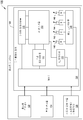
[0063] 도 1b는 호스트 디바이스의 예시적 블록도를 도시한다.
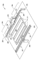
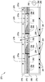
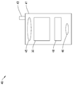
[0064] 도 2a는 예시적 셔터-기반 광 변조기의 예시적 투시도를 도시한다.
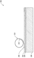
[0065] 도 2b는 롤링 작동기 셔터-기반 광 변조기의 단면도를 도시한다.
[0066] 도 2c는 예시적인 비 셔터-기반 MEMS 광 변조기의 단면도를 도시한다.
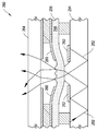
[0067] 도 2d는 전기습윤-기반 광 변조 어레이의 단면도를 도시한다.
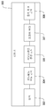
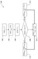
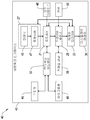
[0068] 도 3은 제어기에 대한 예시적 아키텍처의 블록도를 도시한다.
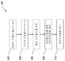
[0069] 도 4는 이미지를 형성하는 예시적 프로세스의 흐름도를 도시한다.
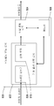
[0070] 도 5는 예시적 서브필드 유도 로직의 블록도를 도시한다.
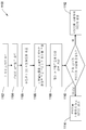
[0071] 도 6은 컬러 서브필드들을 유도하는 예시적 프로세스의 흐름도를 도시한다.
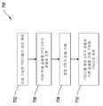
[0072] 도 7은 프레임-특정 기여 컬러(FSCC)를 선택하는 예시적 프로세스의 흐름도를 도시한다.
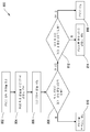
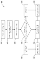
[0073] 도 8a 및 도 8b는 FSCC를 선택하기 위한 부가적인 예시적 프로세스들의 흐름도들을 도시한다.
[0074] 도 9는 도 8a 및 도 8b에 도시된 프로세스들에 사용하기 위한 예시적 FSCC 선택 기준을 묘사하는 두 개의 색 영역들을 도시한다.
[0075] 도 10은 제 2 서브필드 유도 로직의 블록도를 도시한다.
[0076] 도 11은 이미지를 형성하는 다른 예시적 프로세스의 흐름도를 도시한다.
[0077] 도 12는 예시적 컬러 FSCC 스무딩(smoothing) 프로세스의 흐름도를 도시한다.
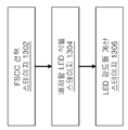
[0078] 도 13은 FSCC를 생성하기 위한 LED 강도들을 계산하는 프로세스의 흐름도를 도시한다.
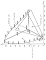
[0079] 도 14는 LED 선택을 위해 세그먼트화된 CIE 컬러 공간에서 디스플레이의 색 영역을 도시한다.
[0080] 도 15는 제 3 서브필드 유도 로직의 블록도를 도시한다.
[0081] 도 16은 7개의 기여 컬러들을 사용하여 컬러 서브필드들을 유도하는 프로세스의 흐름도를 도시한다.
[0082] 도 17 및 도 18은 복수의 디스플레이 엘리먼트들을 포함하는 디스플레이 디바이스를 예시하는 시스템 블록도들을 도시한다.
[0083] 다양한 도면들에서 동일한 참조 번호들 및 지정들은 동일한 엘리먼트들을 표시한다.[0062] Figure Ia illustrates an exemplary schematic diagram of a direct microelectromechanical systems (MEMS) based display device.
[0063] FIG. 1B shows an exemplary block diagram of a host device.
[0064] FIG. 2A illustrates an exemplary perspective view of an exemplary shutter-based optical modulator.
[0065] Figure 2B shows a cross-sectional view of a rolling actuator shutter-based optical modulator.
[0066] FIG. 2C shows a cross-sectional view of an exemplary non-shutter-based MEMS optical modulator.
[0067] Figure 2d shows a cross-sectional view of an electrowetting-based optical modulation array.
[0068] FIG. 3 shows a block diagram of an exemplary architecture for a controller.
[0069] FIG. 4 shows a flow diagram of an exemplary process for forming an image.
[0070] FIG. 5 shows a block diagram of exemplary sub-field derivation logic.
[0071] FIG. 6 shows a flow diagram of an exemplary process for deriving color subfields.
[0072] FIG. 7 shows a flow diagram of an exemplary process for selecting a frame-specific attributed color (FSCC).
[0073] Figures 8A and 8B show flowcharts of additional exemplary processes for selecting FSCC.
[0074] FIG. 9 illustrates two color regions depicting exemplary FSCC selection criteria for use in the processes illustrated in FIGS. 8A and 8B.
[0075] FIG. 10 shows a block diagram of second sub-field derivation logic.
[0076] Figure 11 shows a flow diagram of another exemplary process for forming an image.
[0077] Figure 12 shows a flow diagram of an exemplary color FSCC smoothing process.
[0078] FIG. 13 shows a flow diagram of a process for calculating LED intensities for generating FSCC.
[0079] Figure 14 illustrates the color gamut of a display in a segmented CIE color space for LED selection.
[0080] FIG. 15 shows a block diagram of third sub-field derivation logic.
[0081] FIG. 16 shows a flow diagram of a process for deriving color subfields using seven contribution colors.
[0082] Figures 17 and 18 show system block diagrams illustrating a display device including a plurality of display elements.
[0083] In the various figures, the same reference numerals and designations denote the same elements.
[0084] 본 개시는 이미지 형성 프로세스들 및 그런 프로세스들을 구현하기 위한 디바이스들에 관한 것이다. 이미지 형성 프로세스들은 특히, 배타적이지 않지만, 필드 순차적 컬러(FSC)-기반 디스플레이들에 사용하기에 적당하다. FSC-기반 이미지 형성 프로세스들을 활용할 수 있고, 그러므로 본원에 개시된 프로세스들 및 제어기들의 장점을 취할 수 있는 디스플레이들의 3개의 등급들은 액정 디스플레이(LCD)들, 유기 발광 다이오드(OLED) 디스플레이들, 및 나노전기기계 시스템들(NEMS), 마이크로전기기계 시스템들(MEMS), 및 대규모 EMS 디스플레이들을 포함하는 전기기계 시스템들(EMS) 디스플레이들이다. 그런 프로세스들을 구현하기 위한 디바이스들은 디스플레이 모듈들에 포함된 제어기들; 그래픽 제어기들, 메모리 제어기들, 또는 네트워크 인터페이스 제어기들 같은 다른 타입들의 제어기들; 텔레비전, 모바일 전화들, 스마트 폰들, 랩톱 또는 태블릿 컴퓨터들, 글로벌 네비게이션 위성 시스템(GNSS) 디바이스들, 휴대용 게이밍 디바이스들 등 같은 디스플레이 모듈들을 포함하는 호스트 디바이스들의 프로세스들; 또는 데스크톱 컴퓨터들, 셋톱 박스들, 비디오 게이밍 콘솔들, 디지털 비디오 레코더들, 등 같은 디스플레이 디바이스들 에 이미지 데이터를 출력하는 독립형 디바이스들의 프로세서들을 포함할 수 있다. 이들 디바이스들 각각, 및 다른 유사한 디바이스들은 일반적으로 본원에서 "제어기"들로서 지칭될 것이다.[0084] The present disclosure relates to image forming processes and devices for implementing such processes. Image forming processes are particularly suitable for use with field sequential color (FSC) -based displays, although they are not exclusive. The three classes of displays that can utilize FSC-based image forming processes and thus can take advantage of the processes and controllers disclosed herein are liquid crystal displays (LCDs), organic light emitting diode (OLED) displays, Mechanical systems (NEMS), microelectromechanical systems (MEMS), and electromechanical systems (EMS) displays including large scale EMS displays. Devices for implementing such processes include controllers included in display modules; Other types of controllers, such as graphics controllers, memory controllers, or network interface controllers; Processes of host devices including display modules such as televisions, mobile phones, smart phones, laptop or tablet computers, global navigation satellite system (GNSS) devices, portable gaming devices, etc.; Or autonomous devices that output image data to display devices such as desktop computers, set top boxes, video gaming consoles, digital video recorders, and the like. Each of these devices, and other similar devices, will generally be referred to herein as "controllers ".
[0085] 하나의 이미지 형성 프로세스에서, 제어기는 디스플레이 상에 이미지 프레임을 형성하기 위하여 프레임-독립적 기여 컬러(FICC)들의 세트와 함께 사용하기 위한 프레임-특정 기여 컬러(FSCC)를 선택한다. 몇몇 구현들에서, 제어기는 이미지 프레임의 컬러 콘텐츠에 기초하여 현재 이미지 프레임에 대한 FSCC를 선택한다. 몇몇 다른 구현들에서, 제어기는 현재 이미지 프레임의 제어 콘텐츠에 기초하여 차후 이미지 프레임에 대한 FSCC를 선택한다.[0085] In one image forming process, the controller selects a frame-specific attributed color (FSCC) for use with a set of frame-independent contributing colors (FICCs) to form an image frame on the display. In some implementations, the controller selects the FSCC for the current image frame based on the color content of the image frame. In some other implementations, the controller selects the FSCC for a subsequent image frame based on the control content of the current image frame.
[0086] 몇몇 구현들에서, 제어기는 잠재적 FSCC들의 미리 선택된 세트 중 하나를 선택하도록 구성된다. 예를 들어, 제어기는 백색, 노랑색, 자홍색 및 청록색을 사용하여 그 사이를 선택하도록 구성될 수 있다. 몇몇 다른 구현들에서, 제어기는 FSCC를 선택하는데 큰 융통성을 가지도록 구성되고 이용 가능한 색 영역 내에서, 또는 이용 가능한 색 영역의 경계들에 근접한 정의된 구역들 내에서 임의의 컬러를 선택할 수 있다. 몇몇 다른 구현들에서, 제어기는 이미지 프레임 단위로 FSCC의 변화를 제한하도록 구성된다.[0086] In some implementations, the controller is configured to select one of the preselected sets of potential FSCCs. For example, the controller can be configured to use white, yellow, magenta, and cyan to select between them. In some other implementations, the controller may be configured to have greater flexibility in selecting the FSCC and to select any color within the available color gamut, or within defined regions adjacent to the boundaries of the available gamut. In some other implementations, the controller is configured to limit the variation of FSCC on an image frame basis.
[0087] 몇몇 구현들에서, 제어기는 이미지 프레임 내 FSCC의 우세성에 기초하여 FSCC를 선택한다. 몇몇 다른 구현들에서, 제어기는 이미지 프레임 내 픽셀들의 적어도 서브세트에 대한 중앙 3자극 값들을 결정함으로써 FSCC를 선택한다. 몇몇 구현들에서, 제어기는 또한 프레임 단위로 FSCC가 변화하는 정도를 제한하도록 구성된다.[0087] In some implementations, the controller selects the FSCC based on the dominance of the FSCC in the image frame. In some other implementations, the controller selects the FSCC by determining the central triad stimulus values for at least a subset of the pixels in the image frame. In some implementations, the controller is also configured to limit the degree to which the FSCC varies on a frame-by-frame basis.
[0088] FSCC가 선택된 후, 제어기는 FSCC에 대한 컬러 서브필드를 생성하도록 구성된다. 제어기는 최대 대체 전략, 감소된-서브프레임 대체 전략, 및 부분 대체 전략을 포함하는 다양한 전략들을 사용하여 서브필드를 생성할 수 있다. 제어기는 또한 상이한 대체 전략들을 사용하여 그 사이에서 스위칭하도록 구성될 수 있다.[0088] After the FSCC is selected, the controller is configured to generate a color subfield for the FSCC. The controller can generate the subfields using various strategies including the maximum alternate strategy, the reduced-subframe replacement strategy, and the partial replacement strategy. The controller can also be configured to switch between them using different alternative strategies.
[0089] 그 다음 제어기는 FICC 서브필드들의 초기 세트를 업데이트하도록 FSCC 서브필드를 사용한다. 몇몇 구현들에서, 제어기는, FICC들을 업데이트하기 전에 유도된 FSCC 서브필드에 공간 디더링 알고리즘을 적용하고, 디더링된 FSCC 서브필드를 FICC 서브필드들을 업데이팅하기 위한 기초로서 사용한다.[0089] The controller then uses the FSCC subfield to update the initial set of FICC subfields. In some implementations, the controller applies a spatial dithering algorithm to the derived FSCC subfields before updating the FICCs and uses the dithered FSCC subfields as a basis for updating the FICC subfields.
[0090] 몇몇 다른 구현들에서, 각각의 이미지 프레임에 대한 FSCC를 선택하는 대신, 제어기는 각각의 이미지 프레임에 대한 다수의 프레임-독립적 컴포지트 기여 컬러(CCC) 서브필드들을 유도하도록 구성된다. 예를 들어, 제어기는 각각의 이미지 프레임에 대한 백색, 노랑색, 자홍색, 및 청록색 서브필드들을 유도할 수 있다. 그 다음 제어기는 이미지 프레임으로 하여금 입력 기여 컬러(ICC) 서브필드들의 세트 및 유도된 CCC 서브필드들에 대응하는 서브프레임들을 출력함으로써 디스플레이되게 한다.[0090] In some other implementations, instead of selecting the FSCC for each image frame, the controller is configured to derive a number of frame-independent Composite Contributed Color (CCC) sub-fields for each image frame. For example, the controller may derive white, yellow, magenta, and cyan sub-fields for each image frame. The controller then causes the image frame to be displayed by outputting subframes corresponding to a set of input attributed color (ICC) subfields and derived CCC subfields.
[0091] 또한 몇몇 다른 구현들에서, 제어기는 전력 관리 로직을 포함한다. 전력 관리 로직은 그렇게 수행할 때 소비될 추가 전력이 그들의 사용을 정당화하지 않을 때 CCC 서브필드들(FSCC 서브필드들 또는 프레임-독립 CCC 서브필드들)로부터 디스플레이를 방지하도록 구성된다. 예를 들어, 몇몇 구현들에서, 전력 관리 로직은, 그렇게 수행하는 것이 단지 ICC들만을 사용하여 이미지를 제시할 필요가 있는 미리 결정된 전력 정도를 넘어서 보다 많이 요구할 것이면 디스플레이가 CCC 서브필드들을 사용하여 이미지를 제시하는 것을 방지한다.[0091] Also, in some other implementations, the controller includes power management logic. The power management logic is configured to prevent display from CCC sub-fields (FSCC sub-fields or frame-independent CCC sub-fields) when the additional power to be consumed in doing so does not justify their use. For example, in some implementations, the power management logic may use the CCC subfields to determine whether the display will require more than a predetermined power level that needs to present the image using only ICCs, .
[0092] 본 개시에 설명된 청구 대상의 특정 구현들은 다음 잠재적 장점들 중 하나 또는 그 초과를 실현하도록 구현될 수 있다. 일반적으로, 본원에 개시된 이미지 형성 프로세스들은 FSC 기반 디스플레이들에서 색 분리(CBU)를 완화한다. 이미지 형성 프로세스들은 조명 에너지를 포화 기여 컬러들로부터 멀어지게 전달하고 이미지 프레임에서 우세한 하나 또는 그 초과의 컴포지트 기여 컬러(CCC)들을 사용하는 대신 상기 에너지를 디스플레이함으로써 그렇게 수행한다.[0092] Certain implementations of the claimed subject matter described in this disclosure may be implemented to realize one or more of the following potential advantages. Generally, the image forming processes disclosed herein relax color separation (CBU) in FSC-based displays. Image forming processes do so by conveying the illumination energy away from saturating contributing colors and displaying the energy instead of using one or more of the Composite Contributing Colors (CCC) predominant in the image frame.
[0093] 몇몇 구현들에서, CCC는 프레임-특정 방식으로 선택되어, 이미지 프레임에 특정하게 타겟화된 FSCC 서브필드를 양산한다. 이것은 다수의 CCC들을 사용하는 것과 비교하여 이미지 서브프레임들을 생성 및 제시하는 것과 연관된 에너지 소비를 감소시킨다. 몇몇 구현들에서, 시간 및 에너지 로드는 FICC들의 세트에 대해 제시된 것보다 FSCC에 대해 보다 적은 서브프레임들을 제시함으로써 추가로 감소된다. 몇몇 구현들에서, 콘텐츠 적응 백라이트 제어(CABC) 로직은 또한 각각의 이미지 프레임에 대한 하나 또는 그 초과의 기여 컬러들에 대해 LED 강도를 동적으로 세팅하도록 적용될 수 있다. CABC는 보다 낮은 강도를 가능하게 하고, 그러므로 보다 높은 효율성, LED 조명을 가능하게 한다. CCC에 대해 보다 적은 서브프레임들을 사용하여 발생하는 DFC는 공간 디더링을 통하여 완화될 수 있다. 몇몇 다른 구현들에서, FSCC가 프레임 단위로 변화하도록 허용되는 정도에 대한 제한들이 두어질 수 있어서, 깜박거림 도입의 가능성을 감소시킨다. 이들 피처들 중 하나 또는 그 초과를 사용하여, 이미지 프레임들은 증가된 전력 효율성 및 보다 적은 이미지 아티팩트(artifact)들로 재생될 수 있다.[0093] In some implementations, the CCC is selected in a frame-specific manner to produce an FSCC subfield targeted specifically to an image frame. This reduces the energy consumption associated with creating and presenting image subframes compared to using multiple CCCs. In some implementations, the time and energy load is further reduced by presenting fewer subframes for the FSCC than suggested for the set of FICCs. In some implementations, content adaptive backlight control (CABC) logic may also be applied to dynamically set the LED intensity for one or more contributing colors for each image frame. CABC enables lower intensity, and therefore higher efficiency, LED illumination. DFCs generated using fewer subframes for CCC can be mitigated through spatial dithering. In some other implementations, limitations may be placed on the degree to which the FSCC is allowed to vary frame by frame, thereby reducing the likelihood of introducing flicker. Using one or more of these features, image frames can be reproduced with increased power efficiency and less image artifacts.
[0094] 몇몇 구현들에서, FSCC는 이전 프레임의 컬러 콘텐츠에 기초하여 이미지 프레임에 대해 선택된다. 이것은 서브필드 유도 프로세스가 다음 프레임에 사용될 FSCC를 결정하는 것과 동시에 수행되게 한다. 또한 FSCC 선택을 위하여 프로세싱 중인 동안 프레임 버퍼에 이미지 프레임을 저장하지 않고 선택될 FSCC의 선택을 용이하게 한다. 몇몇 다른 구현들에서, FSCC는 상기 이미지 프레임의 콘텐츠에 기초하여 이미지 프레임에 대해 선택된다. 그렇게 하는 것은 특히 빠르게 가변하는 이미지 콘텐츠를 가진 비디오 데이터에 대해, 이미지 프레임에 FSCC의 보다 밀접한 매칭을 가능하게 한다.[0094] In some implementations, the FSCC is selected for the image frame based on the color content of the previous frame. This allows the subfield derivation process to be performed at the same time as determining the FSCC to be used in the next frame. It also facilitates the selection of the FSCC to be selected without storing the image frame in the frame buffer during processing for FSCC selection. In some other implementations, the FSCC is selected for the image frame based on the content of the image frame. Doing so enables a closer matching of the FSCC to the image frame, especially for video data with rapidly varying image content.
[0095] 몇몇 다른 구현들에서, 감소된 프로세싱 로딩 접근법이 취해지고, 여기서 다수의 CCC들은 모든 각각의 이미지 프레임에 대해 조명된다. 입력 기여 컬러들의 세트에 부가하여, 다수의 CCC들을 사용하는 것은 어느 CCC가 가장 이익일 것인지를 결정하기 위하여 이미지 데이터 모든 각각의 이미지 프레임을 분석하는 프로세서 없이 CBU를 감소시키는 것을 돕는다. 게다가, 몇몇 이미지들은 하나보다 많은 컴포지트 기여 컬러의 상당 수의 픽셀들을 가진다. 그런 경우들에서, 하나의 CCC 만을 사용하는 것은 CBU를 충분히 해결하지 못할 수 있다. 다수의 CCC들을 사용하는 것은 개선된 이미지 품질을 위하여 그런 CBU를 추가로 완화한다.[0095] In some other implementations, a reduced processing loading approach is taken wherein multiple CCCs are illuminated for every respective image frame. In addition to the set of input attributed colors, using multiple CCCs helps to reduce the CBU without a processor that parses each and every image frame of image data to determine which CCC is the most profitable. In addition, some images have a significant number of pixels of more than one composite contributing color. In such cases, using only one CCC may not adequately resolve the CBU. Using multiple CCCs further mitigates such CBU for improved image quality.
[0096] 도 1a는 직시 MEMS-기반 디스플레이 장치(100)의 개략도를 도시한다. 디스플레이 장치(100)는 행들 및 열들로 배열된 복수의 광 변조기들(102a-102d)(일반적으로 "광 변조기들(102)")을 포함한다. 디스플레이 장치(100)에서, 광 변조기들(102a 및 102d)은 개방 상태에 있고, 광이 통과하게 허용한다. 광 변조기들(102b 및 102c)은 폐쇄 상태에 있고, 광의 통과를 방해한다. 광 변조기들(102a-102d)의 상태들을 선택적으로 세팅함으로써, 디스플레이 장치(100)는, 만약 램프 또는 램프들(105)에 의해 조명되면 백리트(backlit) 디스플레이에 대한 이미지(104)를 형성하기 위하여 사용될 수 있다. 다른 구현에서, 장치(100)는 장치의 전면으로부터 발생하는 주변 광의 반사에 의해 이미지를 형성할 수 있다. 다른 구현에서, 장치(100)는 즉 전면 광의 활용에 의해, 디스플레이 전면에 포지셔닝된 램프 또는 램프들로부터의 광의 반사에 의해 이미지를 형성할 수 있다.[0096] FIG. 1 a shows a schematic diagram of a direct view MEMS-based
[0097] 몇몇 구현들에서, 각각의 광 변조기(102)는 이미지(104) 내 픽셀(106)에 대응한다. 몇몇 다른 구현들에서, 디스플레이 장치(100)는 이미지(104) 내 픽셀(106)을 형성하기 위하여 복수의 광 변조기들을 활용할 수 있다. 예를 들어, 디스플레이 장치(100)는 3개의 광-특정 광 변조기들(102)을 포함할 수 있다. 특정 픽셀(106)에 대응하는 컬러-특정 광 변조기들(102) 중 하나 또는 그 초과를 선택적으로 개방함으로써, 디스플레이 장치(100)는 이미지(104) 내 컬러 픽셀(106)을 생성할 수 있다. 다른 예에서, 디스플레이 장치(100)는 이미지(104) 내 휘도 레벨을 제공하기 위하여 픽셀(106) 당 둘 또는 그 초과의 광 변조기들(102)을 포함한다. 이미지에 관하여, "픽셀"은 이미지의 해상도에 의해 정의된 가장 작은 픽처(picture) 엘리먼트에 대응한다. 디스플레이 장치(100)의 구조적 컴포넌트들에 관하여, 용어 "픽셀"은 이미지의 단일 픽셀을 형성하는 광을 변조하기 위하여 활용된 결합된 기계적 및 전기적 컴포넌트들을 지칭한다.[0097] In some implementations, each optical modulator 102 corresponds to a
[0098] 디스플레이 장치(100)는 투사 애플리케이션들에서 통상적으로 발견된 이미징 옵틱(optic)들을 포함하지 않을 수 있다는 점에서 직시 디스플레이이다. 투사 디스플레이에서, 디스플레이 장치의 표면상에 형성된 이미지는 스크린 또는 벽 상에 투사된다. 디스플레이 장치는 실질적으로 투사된 이미지보다 작다. 직시 디스플레이에서, 사용자는 광 변조기들 및 선택적으로 디스플레이 상에 보여진 밝기 및/또는 콘트래스트를 강화하기 위한 백라이트 또는 전면 라이트를 포함하는, 디스플레이 장치에서 직접적으로 봄으로써 이미지를 본다.[0098]
[0099] 직시 디스플레이들은 투과성 또는 반사성 모드 어느 하나로 동작할 수 있다. 투과성 디스플레이에서, 광 변조기들은 디스플레이 뒤에 포지셔닝된 램프 또는 램프들로부터 발생하는 광을 필터링하거나 선택적으로 차단한다. 램프들로부터의 광은, 각각의 픽셀이 균일하게 조명될 수 있도록 선택적으로 광가이드 또는 "백라이트"에 주입된다. 투과성 직시 디스플레이들은 종종, 광 변조기들을 포함하는 하나의 기판이 백라이트의 상단에 직접 포지셔닝 되는 샌드위치 어셈블리 어레인지먼트를 가능하게 하도록 투명 또는 유리 기판들 상에 만들어진다.[0099] Direct view displays can operate in either transmissive or reflective mode. In a transmissive display, the light modulators filter or selectively block light from lamps or lamps positioned behind the display. The light from the lamps is selectively injected into the light guide or "backlight" so that each pixel can be uniformly illuminated. Transparent direct displays are often made on transparent or glass substrates to enable sandwich assembly arrangements where one substrate, including optical modulators, is directly positioned on top of the backlight.
[0100] 각각의 광 변조기(102)는 셔터(108) 및 애퍼처(aperture)(109)를 포함할 수 있다. 이미지(104) 내 픽셀(106)을 조명하기 위하여, 셔터(108)는 광이 애퍼처(109)를 통해 뷰어(viewer)를 향해 또는 뷰어쪽으로 통과하는 것을 허용하도록 포지셔닝된다. 픽셀(106)을 조명하지 않게 하기 위하여, 셔터(108)는, 애퍼처(109)를 통한 광의 통과를 방해하도록 포지셔닝된다. 애퍼처(109)는 각각의 광 변조기(102) 내 반사성 또는 광-흡수 재료를 통해 패터닝된 개구에 의해 정의된다.[0100] Each optical modulator 102 may include a
[0101] 디스플레이 장치는 또한 셔터들의 움직임을 제어하기 위한 광 변조기들 및 기판에 연결된 제어 매트릭스를 포함한다. 제어 매트릭스는 픽셀들의 행당 적어도 하나의 기입-가능 상호연결부(110)(또한 "스캔-라인 상호연결부"로서 지칭됨), 픽셀들의 각각의 행에 대해 하나의 데이터 상호연결부(112), 및 모든 픽셀들, 또는 적어도 디스플레이 장치(100) 내 다수의 열들 및 다수의 행들 둘 다로부터의 픽셀들에 공통 전압을 제공하는 하나의 공통 상호연결부(114)를 포함하는, 일련의 전기 상호연결부들(예를 들어, 상호연결부들(110, 112 및 114))을 포함한다. 적당한 전압("기입-가능 전압(VWE)")의 인가에 응답하여, 픽셀들의 주어진 행에 대한 기입-가능 상호연결부(110)는 새로운 셔터 움직임 명령들을 수용하도록 행 내 픽셀들을 준비한다. 데이터 상호연결부들(112)은 데이터 전압 펄스들의 형태의 새로운 움직임 명령들을 통신한다. 데이터 상호연결부들(112)에 인가된 데이터 전압 펄스들은, 몇몇 구현들에서 셔터들의 정전기 움직임에 직접 기여한다. 몇몇 다른 구현들에서, 데이터 전압 펄스들은 스위치들, 예를 들어 광 변조기들(102)에, 데이터 전압들보다 크기 면에서 통상적으로 보다 높은 별도의 작동 전압들의 인가를 제어하는 트랜지스터들 또는 다른 비-선형 회로 엘리먼트들을 제어한다. 그 다음 이들 작동 전압들의 인가는 셔터들(108)의 정전기 구동 움직임을 초래한다.[0101] The display device also includes light modulators for controlling the movement of the shutters and a control matrix connected to the substrate. The control matrix includes at least one write-enabled interconnect 110 (also referred to as a "scan-line interconnect") per row of pixels, one
[0102] 도 1b는 호스트 디바이스(120)(즉, 셀 폰, 스마트 폰, PDA, MP3 플레이어, 테블릿, e-판독기, 넷북, 노트북, 등)의 블록도의 예를 도시한다. 호스트 디바이스(120)는 디스플레이 장치(128), 호스트 프로세서(122), 환경 센서들(124), 사용자 입력 모듈(126), 및 전력 소스를 포함한다.FIG. 1B shows an example of a block diagram of a host device 120 (ie, a cell phone, a smartphone, a PDA, an MP3 player, a tablet, an e-reader, a netbook, a notebook, etc.). The
[0103] 디스플레이 장치(128)는 복수의 스캔 드라이버들(130)(또한 "기입 가능 전압 소스들"로 지칭됨), 복수의 데이터 드라이버들(132)(또한 "데이터 전압 소스들"로 지칭됨), 제어기(134), 공통 드라이버들(138), 램프들(140-146), 램프 드라이버들(148) 및 도 1a에 도시된 광 변조기들(102) 같은 디스플레이 엘리먼트들의 어레이(150)를 포함한다. 스캔 드라이버들(130)은 기입 가능 전압들을 스캔-라인 상호연결부들(110)에 인가한다. 데이터 드라이버들(132)은 데이터 전압들을 데이터 상호연결부들(112)에 인가한다.The
[0104] 디스플레이 장치의 몇몇 구현들에서, 데이터 드라이버들(132)은, 특히 이미지(104)의 휘도 레벨이 아날로그 방식으로 유도되는 경우, 아날로그 데이터 전압들을 디스플레이 엘리먼트들의 어레이(150)에 제공하도록 구성된다. 아날로그 동작시, 광 변조기들(102)은, 중간 전압들의 범위가 데이터 상호연결부들(112)을 통해 인가될 때, 셔터들(108)의 중간 개방 상태들의 범위 그러므로 이미지(104) 내 중간 조명 상태들 또는 휘도 레벨들의 범위를 초래하도록 설계된다. 다른 경우들에서, 데이터 드라이버들(132)은 2, 3 또는 4 디지털 전압 레벨들의 감소된 세트만이 데이터 상호연결부들(112)에 인가하도록 구성된다. 이들 전압 레벨들은 디지털 방식으로, 개방 상태, 폐쇄 상태, 또는 다른 이산 상태를 셔터들(108)의 각각에 세팅하도록 설계된다.[0104] In some implementations of the display device, the data drivers 132 are configured to provide analog data voltages to the array of
[0105] 스캔 드라이버들(130) 및 데이터 드라이버들(132)은 디지털 제어기 회로(134)(또한 "제어기(134)"로서 지칭됨)에 연결된다. 제어기는 행들 및 이미지 프레임들에 의해 그룹화된 미리 결정된 시퀀스들로 구성된, 주로 직렬 방식으로 데이터를 데이터 드라이버들(132)에 전송한다. 데이터 드라이버들(132)은 직렬 투 병렬 데이터 컨버터들, 레벨 시프팅(shifting), 및 몇몇 애플리케이션들에 대해 디지털 투 아날로그 전압 컨버터들을 포함할 수 있다.[0105]
[0106] 디스플레이 장치는 선택적으로 공통 전압 소스들로서 또한 지칭되는 공통 드라이버들(138)의 세트를 포함한다. 몇몇 구현들에서, 공통 드라이버들(138)은 예를 들어 전압을 일련의 공통 상호연결부들(114)에 공급함으로써, 디스플레이 엘리먼트의 어레이(150) 내의 모든 디스플레이 엘리먼트들에 DC 공통 전위를 제공한다. 몇몇 다른 구현들에서, 제어기(134)로부터 명령들을 따르는 공통 드라이버들(138)은 전압 펄스들 또는 신호들을 디스플레이 엘리먼트들의 어레이(150)에 발행하고, 예를 들어 전압 펄스들 또는 신호들은 어레이(150)의 다수의 행들 및 열들 내 모든 디스플레이 엘리먼트들의 동시 작동을 드라이빙 및/또는 개시할 수 있는 글로벌 작동 펄스들이다.[0106] The display device optionally includes a set of
[0107] 상이한 디스플레이 기능들을 위한 모든 드라이버들(예를 들어, 스캔 드라이버들(130), 데이터드라이버들(132) 및 공통 드라이버들(138)은 제어기(134)에 의해 시간 동기화된다. 제어기로부터의 타이밍 커맨드들은 램프 드라이버들(148)을 통하여 적색, 녹색 및 청색 및 백색 램프들(각각 140, 142, 144 및 146)의 조명, 디스플레이 엘리먼트들의 어레이(150) 내의 특정 행들의 기입-가능 및 시퀀싱, 데이터 드라이버들(132)로부터의 전압들의 출력, 및 디스플레이 엘리먼트 작동을 제공하는 전압들의 출력을 조정한다. 몇몇 구현들에서, 램프들은 발광 다이오드(LED)들이다.All drivers (eg, scan
[0108] 제어기(134)는 셔터들(108) 각각이 새로운 이미지(104)에 적당한 조명 레벨들로 재세팅될 수 있는 시퀀싱 또는 어드레싱 방식을 결정한다. 새로운 이미지들(104)은 주기적 간격들로 세팅될 수 있다. 예를 들어, 비디오 디스플레이들에 대해, 비디오의 컬러 이미지들(104) 또는 프레임들은 10 내지 300 헤르쯔(Hz)의 주파수 범위들에서 리프레시(refresh)된다. 몇몇 구현들에서 어레이(150)에 이미지 프레임의 세팅은, 교번 이미지 프레임들이 적색, 녹색 및 청색 같은 컬러들의 교번하는 시리즈로 조명되도록 램프들(140, 142, 144 및 146)의 조명과 동기화된다. 각각의 개별 컬러에 대한 이미지 프레임들은 컬러 서브프레임으로서 지칭된다. 필드 순차적 컬러 프로세스로서 지칭되는 이 프로세스에서, 컬러 서브프레임들이 20 Hz의 초과의 주파수들에서 교번되면, 인간 뇌는 교번하는 프레임 이미지들을 컬러들의 넓고 연속적인 범위를 가진 이미지의 인식으로 평균화할 것이다. 대안 구현들에서, 원색들을 가진 4 또는 그 초과의 램프들은 디스플레이 장치(100)에 이용될 수 있고, 적색, 녹색, 및 청색 이외의 원색들이 이용된다.The
[0109] 몇몇 구현들에서, 디스플레이 장치(100)가 개방 상태와 폐쇄 상태 사이에서 셔터들(108)의 디지털 스위칭을 위하여 설계되는 경우, 제어기(134)는 시분할 그레이 스케일(gray scale)의 프로세스에 의해 이미지를 형성한다. 몇몇 다른 구현들에서, 디스플레이 장치(100)는 픽셀 당 다수의 셔터들(108)의 사용을 통하여 그레이 스케일을 제공할 수 있다.In some implementations, when the
[0110] 몇몇 구현들에서, 이미지 상태(104)에 대하 데이터는 또한 스캔 라인들로 지칭되는 개별 행들의 순차적 어드레싱에 의해 제어기(134)에 의해 디스플레이 엘리먼트 어레이(150)에 로딩된다. 시퀀스에서 각각의 행 또는 스캔 라인에 대해, 스캔 드라이버(130)는 기입-가능 전압을 어레이(150)의 해당 행에 대한 기입 가능 상호연결부(110)에 인가하고, 순차적으로 데이터 드라이버(132)는 선택된 행의 각각의 열에 대해, 원하는 셔터 상태들에 대응하는 데이터 전압들을 공급한다. 이 프로세스는 데이터가 어레이(150) 내 모든 행들에 대해 로딩될 때까지 반복한다. 몇몇 구현들에서, 데이터 로딩을 위한 선택된 행들의 시퀀스는 선형이고, 어레이(150)의 상단으로부터 하단으로 진행된다. 몇몇 다른 구현들에서, 선택된 행들의 시퀀스는, 가상 아티팩트들을 최소화하기 위하여, 의사-랜덤화된다. 그러고 몇몇 다른 구현들에서 시퀀싱은 블록들에 의해 구성되고, 여기서 하나의 블록에 대해, 이미지 상태(104)의 단지 특정 부분에 대한 데이터가 예를 들어 순차적으로 어레이(150)의 단지 매 5번째 행만을 어드레싱함으로써, 어레이(150)에 로딩된다.In some implementations, data for the
[0111] 몇몇 구현들에서, 어레이(150)에 이미지 데이터를 로딩하기 위한 프로세스는 어레이(150) 내 디스플레이 엘리먼트들을 작동하는 프로세스로부터 이윽고 분리된다. 이들 구현들에서, 디스플레이 엘리먼트 어레이(150)는 어레이(150) 내 각각의 디스플레이 엘리먼트에 대한 데이터 메모리 엘리먼트들을 포함할 수 있고 제어 매트릭스는 메모리 엘리먼트들에 저장된 데이터에 따라 셔터들(108)의 동시 작동을 개시하기 위하여, 공통 드라이버(138)로부터 트리거 신호들을 운반하기 위한 글로벌 작동 상호연결부를 포함할 수 있다.[0111] In some implementations, the process for loading image data into the
[0112] 대안적인 구현들에서, 디스플레이 엘리먼트들의 어레이(150) 및 디스플레이 엘리먼트들을 제어하는 제어 매트릭스는 직사각형 행들 및 열들 외의 구성들로 배열될 수 있다. 예를 들어, 디스플레이 엘리먼트들은 6각형 어레이들 또는 곡선형 행들 및 열들로 배열될 수 있다. 일반적으로, 본원에 사용된 바와 같이, 용어 스캔-라인은 기입-가능 상호연결부를 공유하는 임의의 복수의 디스플레이 엘리먼트들을 지칭할 것이다.[0112] In alternative implementations, the control matrix that controls the array of
[0113] 호스트 프로세서(122)는 일반적으로 호스트의 동작들을 제어한다. 예를 들어, 호스트 프로세서(122)는 휴대용 전자 디바이스를 제어하기 위한 일반 또는 특수 목적 프로세서일 수 있다. 호스트 디바이스(120) 내에 포함된 디스플레이 장치(128)에 관하여, 호스트 프로세서(122)는 이미지 데이터뿐 아니라 호스트에 관한 부가적인 데이터를 출력한다. 그런 정보는 주변 광 또는 온도 같은 환경 센서들로부터의 데이터; 예를 들어 호스트의 전력 소스에 남아 있는 전력 양 또는 호스트의 동작 모드를 포함하는 호스트에 관한 정보; 이미지 데이터의 콘텐츠에 관한 정보; 이미지 데이터 타입에 관한 정보; 및/또는 이미징 모드를 선택하는데 사용하기 위한 디스플레이 장치에 대한 명령들을 포함할 수 있다.[0113] The
[0114] 사용자 입력 모듈(126)은 사용자의 개인적 선호도들을, 직접 또는 호스트 프로세서(122)를 통하여 제어기(134)에 전달한다. 몇몇 구현들에서, 사용자 입력 모듈(126)은 사용자가 개인 선호도들 이를 테면 "보다 깊은 컬러", "보다 우수한 콘트래스트", "보다 적은 전력", "증가된 밝기", "스포츠", "라이브 액션", 또는 "애니메이션"을 프로그래밍하는 소프트웨어에 의해 제어된다. 몇몇 다른 구현들에서, 이들 선호도들은 하드웨어, 이를 테면 스위치 또는 다이얼을 사용하여 호스트에 입력된다. 제어기(134)로의 복수의 데이터 입력들은 데이터를 최적을 이미징 특성들에 대응하는 다양한 드라이버들(130, 132, 138 및 148)에 제공하도록 제어기에게 지시한다.[0114] The
[0115] 환경 센서 모듈(124)은 또한 호스트 디바이스(120)의 일부로서 포함될 수 있다. 환경 센서 모듈(124)은 온도 및/또는 주변 조명 조건들 같은 주변 환경에 관한 데이터를 수신한다. 센서 모듈(124)은, 디바이스가 실내 또는 오피스 환경 대 밝은 햇빛에서의 실외 환경 대 야간 실외 환경에서 동작하는지를 구별하도록 프로그램될 수 있다. 센서 모듈(124)은 정보를 디스플레이 제어기(134)에 통신하여, 제어기(134)는 주변 환경에 응답하여 뷰잉 조건들을 최적화할 수 있다.[0115] The environmental sensor module 124 may also be included as part of the
[0116] 도 2a는 예시적인 셔터-기반 광 변조기(200)의 투시도를 도시한다. 셔터-기반 광 변조기(200)는 도 1a의 직시 MEMS 기반 디스플레이 장치(100)에 통합하기에 적당하다. 광 변조기(200)는 작동기(204)에 커플링된 셔터(202)를 포함한다. 작동기(204)는 두 개의 분리된 순응형 전극 빔 작동기들(205)("작동기들(205)")로 형성될 수 있다. 셔터(202)는 한 측을 작동기(205)에 커플링한다. 작동기들(205)은 표면(203)에 실질적으로 평행한 움직임 평면에서 표면(203)을 가로질러 횡단하게 셔터(202)를 움직인다. 셔터(202)의 반대 측은 작동기(204)에 의해 가해진 힘들에 반대의 복원력을 제공하는 스프링(207)에 커플링된다.[0116] FIG. 2A shows a perspective view of an exemplary shutter-based
[0117] 각각의 작동기(205)는 셔터(202)를 로드 앵커(anchor)(208)에 연결하는 순응형 로드 빔(206)을 포함한다. 순응형 로드 빔들(206)과 함께 로드 앵커들(208)은 기계적 지지부들로서 역할을 하여, 셔터(202)가 표면(203)에 가깝게 서스펜딩(suspend)되게 유지한다. 표면(203)은 광의 통과를 허용하기 위하여 하나 또는 그 초과의 애퍼처 홀들(211)을 포함한다. 로드 앵커들(208)은 순응형 로드 빔들(206) 및 셔터(202)를 표면(203)에 물리적으로 연결하고 바이어스 전압, 몇몇 경우들에서 접지에 로드 빔들(206)을 전기적으로 연결한다.Each
[0118] 기판이 실리콘 같이 불투명하면, 애퍼처 홀들(211)은 기판(204)을 관통하여 홀들의 어레이를 에칭함으로써 기판에 형성된다. 기판(204)이 유리 또는 플라스틱 같이 투명하면, 애퍼처 홀들(211)은 기판(203) 상에 증착된 광-차단 재료의 층으로 형성된다. 애퍼처 홀들(211)은 일반적으로 모양이 원형, 타원형, 다각형, 구불구불하거나, 불규칙할 수 있다.[0118] If the substrate is opaque, such as silicon, then the aperture holes 211 are formed in the substrate by etching the array of holes through the
[0119] 각각의 작동기(205)는 각각의 로드 빔(206)에 인접하게 포지셔닝된 순응형 드라이브 빔(216)을 또한 포함한다. 드라이브 빔들(216)은 한 단부에서 드라이브 빔들(216) 사이에 공유된 드라이브 빔 앵커(218)에 커플링한다. 각각의 드라이브 빔(216)의 다른 단부는 움직이도록 자유롭다. 각각의 드라이브 빔(216)은, 드라이브 빔(216)의 자유 단부 및 로드 빔(206)의 앵커된 단부 근처 로드 빔(206)에 가장 밀접하도록 곡선진다.[0119] Each
[0120] 동작시, 광 변조기(200)를 통합한 디스플레이 장치는 드라이브 빔 앵커(218)를 통하여 드라이브 빔들(216)에 전기 전위를 인가한다. 제 2 전기 전위는 로드 빔들(206)에 인가될 수 있다. 드라이브 빔들(216)과 로드 빔들(206) 사이의 결과적인 전위 차는 드라이브 빔들(216)의 자유 단부들을 로드 빔들(206)의 앵커된 단부들로 끌어당기고, 그리고 로드 빔들(206)의 셔터 단부들을 드라이브 빔들(216)의 앵커된 단부들로 끌어당기고, 이에 의해 셔터(202)를 드라이브 앵커(218) 쪽으로 횡으로 드라이빙한다. 순응형 부재들(206)은, 잠재적인 빔들(206 및 216) 양단 전압이 제거될 때, 로드 빔들(206)을 그의 초기 포지션으로 다시 셔터(202)를 밀도록 스프링들로서 작동하고, 로드 빔들(206)에 저장된 스트레스를 해제한다.In operation, the display device incorporating the
[0121] 광 변조기, 이를 테면 광 변조기(200)는 전압들이 제거된 후 셔터를 자신의 정지 위치로 리턴하기 위하여, 스프링 같은 수동 복원력을 포함한다. 다른 셔터 어셈블리들은 셔터를 개방 상태 또는 폐쇄 상태로 움직이기 위하여 "개방" 및 "폐쇄" 작동기들의 이중 세트 및 "개방" 및 "폐쇄" 전극들의 별개의 세트를 포함할 수 있다.The optical modulator, such as the
[0122] 셔터들 및 애퍼처들의 어레이가 적당한 밝기 레벨들을 가진 이미지들, 많은 경우들에서 동적 이미지들을 생성하기 위하여 제어 매트릭스를 통해 제어될 수 있는 다양한 프로세스들이 있다. 몇몇 경우들에서, 제어는 디스플레이의 주변 상 드라이버 회로들에 연결된 행 및 열 상호연결부들의 수동 매트릭스 어레이에 의해 달성된다. 다른 경우들에서 속도, 밝기 레벨 및/또는 디스플레이의 전력 소실 성능을 개선하기 위하여 어레이(소위 액티브 매트릭스)의 각각의 픽셀 내에 스위칭 및/또는 데이터 스토리지 엘리먼트들을 포함하는 것이 적당하다.[0122] There are various processes in which the array of shutters and apertures can be controlled via the control matrix to produce images with appropriate brightness levels, in many cases dynamic images. In some cases, control is accomplished by a passive matrix array of row and column interconnects coupled to peripheral driver circuits of the display. In other cases it is appropriate to include switching and / or data storage elements in each pixel of the array (so-called active matrix) to improve speed, brightness level and / or power dissipation performance of the display.
[0123] 디스플레이 장치(100)는, 대안적인 구현들에서 상기 설명된 셔터 어셈블리(200) 같은 횡적 셔터-기반 광 변조기들 외에 디스플레이 엘리먼트들을 포함한다. 예를 들어, 도 2b는 롤링 작동기 셔터-기반 광 변조기(220)의 단면도를 도시한다. 롤링 작동기 셔터-기반 광 변조기(220)는 도 1a의 MEMS 기반 디스플레이 장치(100)의 대안적인 구현에 통합하기에 적당하다. 롤링 작동기-기반 광 변조기는 고정된 전극 반대편에 배치되고 전기장의 인가 시 셔터로서 기능하도록 특정 방향으로 움직이게 바이어스된 이동 가능 전극을 포함한다. 몇몇 구현들에서, 광 변조기(220)는 기판(228)과 절연 층(224) 사이에 배치된 평면 전극(226) 및 절연 층(224)에 부착된 고정 단부(230)를 가진 이동 가능 전극(222)을 포함한다. 임의의 인가된 전압이 없을 때, 이동 가능 전극(222)의 이동 가능 단부(232)는 롤링된 상태를 생성하기 위하여 고정된 단부(230)를 향해 롤링하도록 자유롭다. 전극들(222 및 226) 사이의 전압의 인가는 이동 가능 전극(222)이 절연 층(224)에 대해 롤링하지 않고 편평하게 놓이게 하여, 기판(228)을 통해 이동하는 광을 차단하는 셔터로서 작동한다. 이동 가능 전극(222)은 전압이 제거된 후 탄성 복원력에 의해 롤링된 상태로 리턴한다. 롤링된 상태로의 바이어스는 이방성 스트레스 상태를 포함하도록 이동 가능 전극(222)을 제조함으로써 달성될 수 있다.The
[0124] 도 2c는 예시적인 비 셔터 기반 MEMS 광 변조기(250)의 단면도를 도시한다. 광 탭(tap) 변조기(250)는 도 1a의 MEMS 기반 디스플레이 장치(100)의 대안적인 구현에 통합하기에 적당하다. 광 탭은 방해된 내부 전반사(TIR)의 원리에 따라 작동한다. 즉, 광(252)은 광 가이드(254)에 도입되고, 간섭 없이 광(252)은 대개 TIR로 인해 자신의 전면 또는 후면 표면들을 통해 광 가이드(254)를 탈출할 수 없다. 광 탭(250)은 광 가이드(254)에 콘택하는 탭 엘리먼트(256)에 응답하여, 탭 엘리먼트(256)에 인접한 광 가이드(254)의 표면상에 부딪히는 광(252)이 탭 엘리먼트(256)를 통하여 뷰어쪽으로 광 가이드(254)를 탈출하는 충분히 높은 굴절률을 가진 탭 엘리먼트(256)를 포함하여, 이미지의 형성에 기여한다.[0124] FIG. 2C shows a cross-sectional view of an exemplary non-shutter-based MEMS
[0125] 몇몇 구현들에서, 탭 엘리먼트(256)는 가요적, 투명 재료의 빔(258)의 일부로서 형성된다. 전극들(260)은 빔(258)의 한 측의 부분들을 코팅한다. 반대 전극들(262)은 광 가이드(254) 상에 배치된다. 전극들(260 및 262) 양단에 전압을 인가함으로써, 광 가이드(254)에 관하여 탭 엘리먼트(256)의 포지션은 광 가이드(254)로부터 광(252)을 선택적으로 추출하도록 제어될 수 있다.[0125] In some implementations, the
[0126] 도 2d는 전기습윤 기반 광 변조 어레이(270)의 예시적 단면도를 도시한다. 전기습윤 기반 광 변조 어레이(270)는 도 1a의 MEMS 기반 디스플레이 장치(100)의 대안적인 구현에 통합을 위해 적당하다. 광 변조 어레이(270)는 광학 공동(274) 상에 형성된 복수의 전기습윤 기반 광 변조 셀들(272a-d)(일반적으로 "셀들(272)")을 포함한다. 광 변조 어레이(270)는 또한 셀들(272)에 대응하는 컬러 필터들(276)의 세트를 포함한다.[0126] FIG. 2d shows an exemplary cross-section of an electrowetting-based
[0127] 각각의 셀(272)은 수분 층(또는 다른 투명 전도성 또는 극성 유체)(278), 광 흡수 오일 층(280), 투명 전극(282)(예를 들어 인듐-주석 산화물(ITO)로 만들어짐) 및 광 흡수 오일 층(280)과 투명 전극(282) 사이에 포지셔닝된 절연 층(284)을 포함한다. 본원에 설명된 구현에서, 전극은 셀(272)의 후 표면의 일부를 차지한다.Each
[0128] 셀(272)의 후면 표면의 나머지는 광학 공동(274)의 전면 표면을 형성하는 반사 애퍼처 층(286)으로 형성된다. 반사 애퍼처 층(286)은 반사 금속 또는 유전체 미러를 형성하는 박막들의 스택 같은 반사 재료로 형성된다. 각각의 셀(272)에 대해, 애퍼처는 광이 통과하게 하도록 반사 애퍼처 층(286)으로 형성된다. 셀에 대한 전극(282)은 애퍼처 내에 그리고 다른 유전체 층에 의해 분리되는 반사 애퍼처 층(286)을 형성하는 재료 위에 증착된다.The remainder of the back surface of the
[0129] 광학 공동(274)의 나머지는 반사 애퍼처 층(286)에 근접하게 포지셔닝된 광 가이드(288), 및 반사 애퍼처 층(286) 반대편 광 가이드(288) 측 상 제 2 반사 층(290)을 포함한다. 일련의 광 리디렉터(redirector)들(291)은 제 2 반사 층에 근접한 광 가이드의 후면 표면상에 형성된다. 광 리디렉터(291)들은 분산 또는 반사성 반사기들일 수 있다. 하나 또는 그 초과의 광 소스들(292), 이를 테면 LED들은 광(294)을 광 가이드(288)에 주입한다.The remainder of the
[0130] 대안적인 구현에서, 부가적인 투명 기판(도시되지 않음)은 광 가이드(288)와 광 변조 어레이(270) 사이에 포지셔닝된다. 이 구현에서, 반사 애퍼처 층(286)은 광 가이드(288)의 표면 대신 부가적인 투명 기판상에 형성된다.[0130] In an alternative implementation, an additional transparent substrate (not shown) is positioned between the
[0131] 동작시, 셀(예를 들어, 셀(272b 또는 272c))의 전극(282)에 전압의 인가는 셀 내 광 흡수 오일(280)이 셀(272)의 일부에 모이게 한다. 결과적으로, 광 흡수 오일(280)은 반사 애퍼처 층(286)(예를 들어 셀들(272b 및 272c) 참조)에 형성된 애퍼처를 통한 광의 통과를 더 이상 방해하지 않는다. 그 다음 애퍼처에서 백라이트를 탈출하는 광은 이미지 내 컬러 픽셀을 형성하기 위하여 컬러 필터들(276)의 세트 내 대응하는 컬러 필터(예를 들어, 적색, 녹색 또는 청색) 및 셀을 통하여 탈출할 수 있다. 전극(282)이 접지될 때, 광 흡수 오일(280)은 반사 애퍼처 층(286) 내 애퍼처를 커버하여, 애퍼처를 통과하려고 시도하는 임의의 광(294)을 흡수한다.In operation, the application of a voltage to the
[0132] 전압이 셀(272)에 인가될 때 오일(280)이 모이는 그 아래 영역은 이미지를 형성하는 것과 관련하여 낭비된 공간을 구성한다. 이 영역은 전압이 인가되든 아니든 비-투과성이다. 그러므로, 반사 애퍼처 층(286)의 반사 부분들의 포함 없이, 이 영역은 광을 흡수하고 그렇지 않으면 이미지의 형성에 기여하기 위하여 사용될 수 있다. 그러나, 반사 애퍼처 층(286)의 포함으로, 그렇지 않으면 흡수될 광이 상이한 애퍼처를 통해 미래에 탈출하기 위하여 광 가이드(290)로 다시 반사된다. 전기습윤 기반 광 변조 어레이(270)는 본원에 설명된 디스플레이 장치에 포함하기에 적당한 비-셔터 기반 MEMS 변조기의 유일한 예가 아니다. 다른 형태들의 비-셔터 기반 MEMS 변조기들은 마찬가지로 본 개시의 범위에서 벗어남이 없이 본원에 설명된 제어기 기능들 중 다양한 기능들에 의해 제어될 수 있다.The lower area where the
[0133] 도 3은 제어기(300)에 대한 예시적 아키텍처의 블록도를 도시한다. 예를 들어, 디스플레이 장치(128)를 제어하기 위하여 도 1b에 도시된 제어기(134)는 유사한 아키텍처에 따라 만들어질 수 있다. 몇몇 다른 구현들에서, 도 3에 도시된 제어기(300)는 디스플레이 상에 제시를 위한 데이터를 프로세싱하는 다른 독립적 디바이스 또는 디스플레이를 포함하는 호스트 디바이스의 프로세서로 구현된다. 제어기(300)는 입력(302), 서브필드 유도 로직(304), 서브프레임 생성 로직(306), 프레임 버퍼(307), 및 출력 제어 로직(308)을 포함한다. 함께, 컴포넌트들은 이미지를 형성하는 프로세스를 수행한다.[0133] FIG. 3 shows a block diagram of an exemplary architecture for
[0134] 입력(302)은 임의의 타입의 제어기 입력일 수 있다. 몇몇 구현들에서, 입력은 HDMI 포트, VGA 포트, DVI 포트, 미니-디스플레이 포트, 동축 케이블 포트, 또는 컴포넌트 또는 컴포지트 비디오 케이블 포트들의 세트 같은, 외부 디바이스로부터 이미지 데이터를 수신하기 위한 외부 데이터 포트이다. 입력(302)은 또한 이미지 데이터를 무선으로 수신하기 위한 트랜시버를 포함할 수 있다. 몇몇 다른 구현들에서, 입력(302)은 디바이스 내부의 프로세서의 하나 또는 그 초과의 데이터 포트들을 포함한다. 그런 데이터 포트들은 메모리 디바이스, 호스트 프로세서, 트랜시버, 또는 상기 설명된 임의의 외부 데이터 포트들로부터 데이터 버스를 통해 디스플레이 데이터를 수신하도록 구성될 수 있다.[0134]
[0135] 서브필드 유도 로직(304), 서브프레임 생성 로직(306), 및 출력 제어 로직(308)은 집적 회로들, 하드웨어 및/또는 펌웨어의 결합으로부터 각각 형성될 수 있다. 예를 들어, 서브필드 유도 로직(304), 서브프레임 생성 로직(306), 및 출력 제어 로직(308) 중 하나 또는 그 초과는 통합될 수 있거나 하나 또는 그 초과의 주문형 집적 회로(ASIC)들, 필드 프로그램 가능 게이트 어레이(FPGA)들, 또는 디지털 신호 프로세서(DSP)들 사이에 분산될 수 있다. 몇몇 다른 구현들에서, 서브필드 유도 로직(304), 서브프레임 생성 로직(306), 및 출력 제어 로직(308)의 일부 또는 모든 기능성은, 프로세서, 이를 테면 범용 또는 특수 목적 프로세서에 의해 실행될 때, 프로세서로 하여금 본원에 설명된 기능성을 수행하게 하는 프로세서 실행 가능 명령들에 통합될 수 있다.The
[0136] 프레임 버퍼(307)는 본원에 개시된 프로세스들을 수용하기에 충분히 빠른 이미지 서브프레임들을 저장 및 출력하기에 충분한 판독 및 기입 속도들을 가진 임의의 형태의 디지털 메모리일 수 있다. 몇몇 구현들에서, 프레임 버퍼(307)는 집적 회로 메모리, 이를 테면 DRAM 또는 플래시 메모리로서 구현된다.[0136] The
[0137] 도 4는 이미지를 형성하기 위한 예시적인 프로세스(400)의 흐름도를 도시한다. 프로세스는 이미지 프레임 데이터를 수신하는 단계(스테이지 402), 이미지 프레임을 사전 프로세싱하는 단계(스테이지 404), 이미지 프레임에 대한 컬러 서브필드들을 유도하는 단계(스테이지 406), 각각의 컬러 서브필드에 대한 서브프레임들을 생성하는 단계(스테이지 408), 및 디스플레이 엘리먼트들의 어레이를 사용하여 서브프레임들을 제시하는 단계(스테이지 410)를 포함한다. 이들 스테이지들 각각은, 도 3에 도시된 제어기(300)의 컴포넌트들과 함께, 아래에 추가로 설명된다.[0137] FIG. 4 shows a flow diagram of an
[0138] 도 1, 도 3 및 도 4를 참조하여, 입력(302)은 디스플레이 장치(128) 상에 제시하기 위한 이미지 데이터를 수신(스테이지 402)하도록 구성된다. 이미지 데이터는 통상적으로 디스플레이 장치(128) 내 각각의 픽셀에 대해, 입력 컬러들, 이를 테면 적색, 녹색 및 청색의 세트 각각에 대한 강도 값들의 스트림으로서 수신된다. 이미지 데이터는 이미지 소스로부터, 즉 디스플레이 장치(128)에 통합된 그런 전자 스토리지 매체로부터 직접 수신될 수 있다. 대안적으로, 이미지 데이터는 디스플레이 장치(128)가 만들어진 호스트 디바이스(120)에 통합된 호스트 프로세서(122)로부터 수신될 수 있다.1, 3, and 4, the
[0139] 몇몇 구현들에서, 수신된 이미지 프레임 데이터는 이미지 형성 프로세스(400)의 나머지가 진행하기 전에 사전 프로세싱(스테이지 404)된다. 예를 들어, 몇몇 구현들에서, 이미지 데이터는 디스플레이 장치(128)에 포함된 것보다 많은 픽셀들 또는 적은 픽셀들에 대한 컬러 강도 값들을 포함한다. 그런 경우들에서, 입력(302), 서브필드 유도 로직(304), 또는 제어기(300)에 통합된 다른 로직은 디스플레이 장치(128)에 포함된 픽셀들의 수로 대략적으로 이미지 데이터를 스케일링할 수 있다. 몇몇 다른 구현들에서, 이미지 프레임 데이터는 수신되어 주어진 디스플레이 감마(gamma)를 추정하여 인코딩되었다. 몇몇 구현들에서, 그런 감마 인코딩이 검출되면, 제어기(300) 내의 로직은 디스플레이 장치(128)의 감마에 대해 보다 적당하도록 픽셀 강도 값들을 조절하기 위하여 감마 정정 프로세스를 적용한다. 예를 들어, 이미지 데이터는 종종 통상적인 액정(LCD) 디스플레이의 감마에 기초로 인코딩된다. 이런 공통 감마 인코딩을 처리하기 위하여, 제어기(300)는 감마 정정 룩업 테이블(LUT)을 저장할 수 있고, LCD 감마 인코딩된 픽셀 값들의 세트가 주어지면 LUT로부터 적당한 강도 값들을 빠르게 리트리브할 수 있다. 몇몇 구현들에서, LUT는, 다른 컬러 해상도들이 다른 구현들에서 사용될 수 있지만, 16 비트-퍼-컬러 해상도를 가진 대응하는 RGB 강도 값들을 포함한다.[0139] In some implementations, the received image frame data is pre-processed (stage 404) before the remainder of the image-forming
[0140] 몇몇 구현들에서, 제어기(300)는 이미지를 사전 프로세싱하는 단계(스테이지 404)의 일부로서 수신된 이미지 프레임에 히스토그램 함수를 적용한다. 히스토그램 함수는 제어기(300)의 다른 컴포넌트들에 의해 사용될 수 있는 이미지 프레임에 관한 다양한 통계치들을 결정한다. 예를 들어, 일 구현에서, 히스토그램 함수는 각각의 FICC에 대해 이미지 프레임 내 FICC의 평균 강도 및 0의 강도 값을 가진 픽셀들의 비율을 계산한다. 이 히스토그램 데이터는 이후 추가로 설명되는 바와 같이 FSCC를 선택하는데 사용될 수 있다.[0140] In some implementations, the
[0141] 제어기(300)는 또한 프레임 단위로 히스토그램 데이터의 히스토리를 저장할 수 있다. 일 구현에서, 연속적인 이미지 프레임들로부터의 히스토그램 데이터는 장면 변화가 발생했는지를 결정하기 위하여 비교된다. 특히, 현재 프레임에 대한 히스토그램 데이터가 이전 이미지 프레임의 히스토그램 데이터로부터 임계치를 넘어 상이하면, 제어기는, 장면 변화가 발생하였다는 것을 결정하고, 현재 이미지 프레임을 이에 따라 프로세싱한다. 예를 들어, 몇몇 구현들에서, 장면 변화를 검출하는 것에 응답하여, 제어기(300)는 검출된 장면 변화가 없다는 것을 사용하지 않기보다 CABC 프로세스를 선택한다.[0141] The
[0142] 몇몇 구현들에서, 이미지 프레임 사전 프로세싱(스테이지 404)은 디더링 스테이지를 포함한다. 몇몇 구현들에서, 이미지를 디-감마 인코딩하는 프로세스는, 비록 디스플레이 장치(128)가 컬러 당 그런 보다 큰 수의 비트들을 디스플레이하기 위하여 구성될 수 없지만, 16개의 비트-퍼-컬러 픽셀 값들을 초래한다. 디더링 프로세스는 이들 픽셀 값들을 디스플레이에 이용 가능한 컬러 해상도, 이를 테면 컬러 당 6 또는 8 비트들로 하향 전환하는 것과 연관된 임의의 양자화 에러를 분산하는 것을 도울 수 있다.[0142] In some implementations, the image frame pre-processing (stage 404) includes a dithering stage. In some implementations, the process of de-gamma encoding an image may result in 16 bit-per-color pixel values, even though the
[0143] 예시적인 디더링 프로세스에서, 제어기는 디스플레이에 의해 사용된 FICC들 각각에 대한 그들의 초기 보다 큰 수의 비트들 표현과 그들의 양자화된 표현 사이의 차이를 각각의 픽셀에 대해 계산한다. 이 예에 대해, FICC들이 적색, 녹색 및 청색임을 가정한다. 차이 계산은 아래와 같이 표현될 수 있다:[0143] In an exemplary dithering process, the controller calculates for each pixel the difference between their initial larger number of bits representation and their quantized representation for each of the FICCs used by the display. For this example, it is assumed that the FICCs are red, green, and blue. The difference calculation can be expressed as:
![]()
![]()
여기서 RQ , GQ, 및 BQ는 픽셀에 대한 양자화된 적색, 녹색, 및 청색 강도 값을 표현하고; R, G, 및 B는 양자화되지 않은 적색, 녹색, 및 청색 강도 값들을 표현하고; 그리고 ΔR, ΔG, 및 ΔB는 그들의 개별 차이들을 표현한다. 이들 차이 값들로부터, 제어기는 각각의 픽셀에 대한 결과적인 강도 에러 값(ΔL)을 계산한다. 밝기 에러(ΔL)는 다음과 같이 계산될 수 있다:Where R Q , G Q , and B Q represent quantized red, green, and blue intensity values for a pixel; R, G, and B represent non-quantized red, green, and blue intensity values; And [Delta] R, [Delta] G, and [Delta] B represent their individual differences. From these difference values, the controller calculates the resulting intensity error value [Delta] L for each pixel. The brightness error ([Delta] L) can be calculated as follows:
![]()
![]()
여기서 Yr gamut, Yg gamut, 및 Yb gamut 은 디스플레이가 동작하는 컬러 색역에 사용된 적색, 녹색, 및 청색 원색들의 3자극 값들의 Y 컴포넌트를 표현한다. 그 다음 제어기(300)는 결정된 밝기 에러들에 기초하여 각각의 픽셀의 적색, 녹색, 및 청색 강도 값들에 적당한 증가들을 식별하고 적용한다. 일 구현에서, 증가들은 LUT를 사용하여 식별된다. LUT에 기초하여 픽셀 강도 값들을 증가한 후, 제어기(300)는 픽셀의 초기 비양자화된 값과 그들의 새로운 양자화된 값들 사이의 업데이트된 차이를 재계산한다. 픽셀에 대한 이 차이는 다음과 같이 표현될 수 있다:Where Y r gamut , Y g gamut , and Y b gamut represent the Y component of the three stimulus values of the red, green, and blue primary colors used in the color gamut in which the display operates. The
![]()
![]()
여기서 LUTR(ΔL), LUTG(ΔL), LUTB(ΔL)은 이전에 계산된 밝기 에러(ΔL)에 기초하여 LUT로부터 얻어진 픽셀에 대한 적색, 녹색, 및 청색 강도들을 증가시킬 값들을 표현한다. 이들 새로운 차이 값들은 컬러의 부가로 인한 더 우수한 밝기를 표현하지만, 현재 컬러 에러를 포함하고, 그 다음 컬러 에러는 에러 분산 알고리즘을 사용하여 이웃 픽셀들 사이에 분산된다. 몇몇 구현들에서, 에러는 하드-코딩된 5x5 커널을 사용하는 플로이드-스타인베르크(Floyd-Steinberg) 디더링 알고리즘을 사용함으로써 분산된다. 몇몇 다른 구현들에서, 다른 커널 크기들, 및/또는 상이한 디더링 알고리즘 또는 디더 마스크들이 이용된다. 결과적으로, 양자화로부터 발생하는 밝기 에러들은 분산 방식으로 FICC 컬러 채널들에 부가적인 밝기를 분산함으로써 정정되고, 특히 HVS가 검출하기 위하여 도전하는 정정을 제공한다.Where LUT R (? L), LUT G (? L), and LUT B (? L) represent values that will increase the red, green, and blue intensities for the pixels obtained from the LUT based on the previously calculated brightness error do. These new difference values represent better brightness due to the addition of color, but include the current color error, and then the color error is distributed among the neighboring pixels using an error distribution algorithm. In some implementations, the error is distributed using a Floyd-Steinberg dithering algorithm using a hard-coded 5x5 kernel. In some other implementations, different kernel sizes, and / or different dithering algorithms or dither masks are used. As a result, the brightness errors resulting from the quantization are corrected by distributing the additional brightness to the FICC color channels in a distributed fashion, in particular providing a correction that the HVS is challenging to detect.
[0144] 사전 프로세싱이 완료된 후, 서브필드 유도 로직(304)은 수신된 이미지 데이터를 프로세싱하고 이를 컬러 서브필드들로 전환(스테이지 406)하고, 그 다음 이미지 데이터로 인코딩된 이미지를 재생성하기 위하여 사용자에게 디스플레이될 것이다. 몇몇 구현들에서, 서브필드 유도 로직(304)은 임의의 주어진 이미지 프레임을 형성하기 위하여 입력 컬러들에 부가하여 사용할 하나 또는 그 초과의 컴포지트 컬러들을 동적으로 선택할 수 있다. 컴포지트 컬러는 둘 또는 그 초과의 입력 컬러들의 결합으로부터 형성된 컬러이다. 예를 들어, 노랑색은 적색 및 녹색의 컴포지트이고, 백색은 적색, 녹색 및 청색의 컴포지트이다. 몇몇 다른 구현들에서, 서브필드 유도 로직(304)은 이미지를 형성하기 위하여 입력 컬러들에 더하여 둘 또는 그 초과의 컴포지트 컬러들을 사용하도록 사전 구성된다. 또 몇몇 다른 구현들에서, 서브필드 유도 로직(304)은 그런 사용이 전력 절약들을 초래할 것인지에 따라 이미지를 형성하기 위하여 임의의 컴포지트 컬러들을 사용할지 아닐지 여부를 각각의 이미지 프레임에 대해 결정하도록 구성된다. 이들 구현들 각각에서, 서브필드 유도 로직(304)은 디스플레이되는 각각의 픽셀에 대해, 이미지를 형성하기 위하여 사용된 각각의 컬러(일반적으로 "기여 컬러"라 지칭됨)에 대해 강도 값들의 세트를 생성한다. 이들 구현들 각각에 관한 추가 상세들은 이후 제공된다.After the pre-processing is completed, the
[0145] 서브프레임 생성 로직(306)은 서브필드 유도 로직(304)에 의해 유도된 컬러 서브필드들을 취하고 수신된 이미지 데이터로 인코딩된 이미지를 재생하기 위하여, 도 1b에 도시된 디스플레이 엘리먼트들의 어레이(150) 같은 디스플레이 엘리먼트들의 어레이에 로딩될 수 있는 서브프레임들의 세트를 생성(스테이지 408)한다. 각각의 디스플레이 엘리먼트가 두 개의 상태들, 즉 온 또는 오프로만 놓여질 수 있는 이진 디스플레이에 대해, 서브프레임 생성 로직(306)은 비트판(bitplane)들의 세트를 생성한다.[0145] The
[0146] 각각의 비트판은 주어진 서브프레임에 대한 어레이에서 디스플레이 엘리먼트들 각각의 원하는 상태들을 식별한다. 감소된 수의 비트판들로 달성될 수 있는 그레이스케일 값들의 수를 증가시키기 위하여, 서브프레임 생성 로직(306)은 각각 서브프레임에 가중을 할당한다. 몇몇 구현들에서, 각각의 비트판은 주어진 컬러에 대한 각각의 연속적인 서브프레임에 다음 가장 낮은 가중, 예를 들어 1, 2, 4, 8, 16, 32 등을 가진 서브프레임의 두 배인 가중이 할당되는 이진 가중 방식에 따라 가중이 할당된다. 몇몇 다른 구현들에서, 가중들은 비-이진 가중 방식에 따라 하나 또는 그 초과의 컬러들과 연관된 서브프레임들에 할당된다. 그런 비-이진 가중 방식들은 가중들이 다음 가장 낮은 가중을 가진 서브프레임의 가중의 두 배보다 많거나 적은 동일한 가중 및/또는 서브프레임들을 가진 다수의 서브프레임들을 포함할 수 있다.[0146] Each bit plate identifies the desired states of each of the display elements in the array for a given sub-frame. In order to increase the number of gray scale values that can be achieved with a reduced number of bit plates, the sub
[0147] 서브프레임을 생성하기 위하여(스테이지 408), 서브프레임 생성 로직(306)은 컬러 강도 값을 코드워드라 지칭되는 1들 및 0들의 이진 문자열로 번역한다. 1들 및 0들은 이미지 프레임에 대한 컬러에 대한 각각의 서브프레임에서 주어진 디스플레이 엘리먼트들의 원하는 상태들을 표현한다. 몇몇 구현들에서, 서브프레임 생성 로직(306)은 각각의 강도 값을 코드워드와 연관시키는 LUT를 포함하거나 액세스한다. 그 다음 각각의 픽셀에 대한 각각의 컬러에 대한 코드워드들은 프레임 버퍼(307) 내에 저장된다.[0147] To generate a sub-frame (stage 408), the
[0148] 출력 제어 로직(308)은 서브프레임 생성 로직(306)에 의해 생성된 서브프레임들이 뷰어에게 제시(스테이지 410)게 하도록 디스플레이 장치의 컴포넌트의 나머지로의 신호들의 출력을 제어하도록 구성된다. 예를 들어, 도 1b에 도시된 디스플레이 장치(128)에 사용되면, 출력 제어 로직(308)은 어레이(150) 내 디스플레이 엘리먼트들에 비트판들을 로딩하고, 그 다음 램프들(140, 142, 144 및 146)로 디스플레이 엘리먼트들을 조명하기 위하여 도 1b에 도시된 데이터 드라이버들(132), 스캔 드라이버들(130) 및 램프 드라이버들(148)로의 신호들의 출력을 제어한다. 출력 제어 로직(308)은 서브프레임 생성 로직(308)에 의해 생성된 서브프레임들 각각이 데이터 드라이버들(132)에 출력하여야 하는 시간들, 스캔 드라이버들(130)이 트리거되어야 하는 때, 및 램프 드라이버들(148) 각각의 트리거되어야 하는 때를 표시하는 스케쥴링 데이터를 포함한다.The
[0149] 도 5는 예시적인 서브필드 유도 로직(500)의 블록도를 도시한다. 서브필드 유도 로직(500)은 기여 컬러 선택 로직(502), 픽셀 변환 로직(504), 및 메모리(506)를 포함한다. 서브필드 유도 로직(500)은 FICC들의 세트와 함께 동적으로 선택된 FSCC를 사용하여 각각 수신된 이미지 프레임을 뷰어에게 제시하도록 컬러 서브필드들의 세트를 생성하게 구성된다. 그런 컬러 서브필드들을 유도하기 위한 하나의 프로세스는 도 6에 도시된다.[0149] FIG. 5 shows a block diagram of an exemplary
[0150] 도 6은 컬러 서브필드들을 유도하는 예시적 프로세스(600)의 흐름도를 도시한다. 프로세스(600)는 도 4에 도시된 이미지(400)를 형성하는 프로세스의 스테이지(406)를 수행하기 위하여 사용될 수 있다. 프로세스(600)는 이미지 프레임을 수신하는 단계(스테이지 602), 이미지를 형성하는데 사용하기 위하여 FSCC를 얻는 단계(스테이지 604), 이미지 프레임에 대한 FSCC에 대한 컬러 서브필드를 유도하는 단계(스테이지 606), 및 그 다음 FSCC 서브필드 픽셀 값들에 기초하여 FICC들의 컬러 서브필드들을 조절하는 단계(스테이지 608)를 포함한다. 이들 스테이지들 각각뿐 아니라, 서브필드 유도 로직(500)의 컴포넌트들은 아래에 추가로 설명된다.[0150] FIG. 6 shows a flow diagram of an
[0151] 도 5 및 도 6을 참조하여, 상기 설명된 바와 같이, 컬러 서브필드들을 유도하는 프로세스(600)는 이미지 프레임을 수신하는 것에서 시작한다(스테이지 602). 이미지 프레임은 예를 들어 도 3에 도시된 제어기(300)의 입력(302)으로부터 수신될 수 있다. 수신된 이미지 프레임은 기여 컬러 선택 로직(502)으로 전달된다.[0151] Referring to Figures 5 and 6, as described above, the
[0152] 기여 컬러 선택 로직(502)은 이미지를 형성하는데 사용할 FSCC를 얻도록(스테이지 604) 구성된다. 몇몇 구현들에서, 기여 컬러 선택 로직(502)은 해당 이미지 프레임과 연관된 이미지 데이터를 사용하여 이미지를 형성하는데 사용할 FSCC를 얻도록 구성된다. 몇몇 다른 구현들에서, 기여 컬러 선택 로직(502)은 하나 또는 그 초과의 이전 이미지 프레임들과 연관된 이미지 데이터에 기초하여 이미지 프레임에 대한 FSCC를 얻는다. 그런 구현들에서, 기여 컬러 선택 로직(502)은 현재 이미지 프레임을 분석하고 메모리(506) 내 차후 이미지 프레임에 사용될 FSCC를 저장(스테이지 605)하고 메모리(506)로부터 이전 이미지 프레임에 기초하여 저장된 FSCC 선택을 리트리빙함으로써 현재 프레임에 사용할 FSCC를 얻는다(스테이지 604).[0152] The contribution
[0153] FSCC(현재 이미지 프레임 또는 차후 이미지 프레임 어느 하나)를 선택하기 위하여, 기여 컬러 선택 로직(502)은 프레임 분석기(508) 및 선택 로직(510)을 포함한다. 일반적으로, 프레임 분석기(508)는 그의 전체 컬러 특성들을 결정하기 위하여 이미지 프레임을 분석하고, 그 출력에 기초하여, 선택 로직(510)은 FSCC를 선택한다. 기여 컬러 선택 로직(502)이 FSCC를 선택할 수 있는 예시적 프로세스들은 도 7-도 9에 관련하여 아래에 추가로 설명된다.The contribution
[0154] 도 7은 FSCC를 선택하는 예시적 프로세스(700)의 흐름도를 도시한다. FSCC 선택 프로세스(700)는 기여 컬러 선택 로직(502)에 의해 실행하기에 적당한 FSCC 선택 프로세스의 예이다. 프로세스(700)는 기여 컬러 선택 로직(502)에게 선택할 이용 가능한 FSCC들의 세트를 제공하는 단계(스테이지 702), 수신된 이미지 데이터를 프로세싱하기 위한 XYX 3자극 값들로 전환하는 단계(스테이지 706), 3자극 값들의 중앙에 대응하는 컬러를 식별하는 단계(스테이지 708), 및 세트 평균 3자극 값들에 대응하는 컬러에 가장 근접한 이용 가능한 FSCC로 FSCC를 세팅하는 단계(스테이지 710)를 포함한다.[0154] FIG. 7 shows a flow diagram of an
[0155] 도 5 및 도 7을 참조하여, 프로세스(700)는 기여 컬러 선택 로직(502)이 임의의 주어진 이미지 프레임에 사용할 이용 가능한 FSCC들의 미리 결정된 세트 중 단지 하나만을 선택하도록 구성된다는 것을 보장한다. 컴포지트 컬러들의 미리 결정된 세트로부터 FSCC를 선택하는 것은 FSCC 선택 스테이지(스테이지 708)뿐 아니라 도 6에 도시된 FICC 서브필드 조절 스테이지(스테이지 608) 둘 다를 단순화할 수 있다. 따라서, 프로세스(700)는 이용 가능한 FSCC들의 세트를 기여 컬러 선택 로직(502)에 제공(스테이지 702)에서 시작한다.[0155] Referring to Figures 5 and 7, the
[0156] 대부분의 이미지 데이터는 적색, 녹색 및 청색 픽셀 값들의 형태로 수신된다. 따라서, 몇몇 구현들에서, 기여 컬러 선택 로직(502)을 포함하는 서브필드 유도 로직(500)을 포함하는 디스플레이는 적색, 녹색, 청색 및 몇몇 경우들에서 각각의 이미지 프레임과 연관된 대응하는 서브필드들을 조명하기 위하여 백색 LED들을 사용한다. 적색, 녹색 및 청색의 이용은 프레임-독립적이고, 그런 컬러들은 FICC들로 지칭된다. 몇몇 구현들에서, 제공된 FSCC들은 FICC들 중 둘 또는 그 초과의 동일한 결합들로부터 형성된 컬러들을 포함한다. 예를 들어, 이용 가능 FSCC들은 노랑색(적색과 녹색의 결합으로 형성됨), 청록색(녹색과 청색의 결합으로 형성됨), 자홍색(적색과 청색의 결합으로 형성됨), 및 백색(적색, 녹색 및 청색의 결합으로 형성됨)을 포함할 수 있다. 그런 FSCC들은 디스플레이의 LED들 중 둘 또는 그 초과를 조명함으로써, 또는 예를 들어 백색의 경우, FSCC를 직접 출력하도록 설계된 독립된 LED에 의해 생성될 수 있다.[0156] Most of the image data is received in the form of red, green, and blue pixel values. Thus, in some implementations, the display including the
[0157] FSCC의 선택은 선형 컬러 공간을 평가할 때 매우 효과적일 수 있다. RGB 컬러 공간은 비선형이지만 XYZ 컬러 공간은 선형이다. 따라서, 프레임 분석기(508)는 픽셀 프레임의 각각의 픽셀의 값들을 프로세싱하여 이들을 XYZ 컬러 공간으로 전환한다(스테이지 706). 전환은 XYZ 변환 매트릭스(M)와 픽셀![]()
![]()

![]()
![]()
![]()
![]()
![]()
![]()
![]()
![]()
![]()
![]()
![]()
![]()
![]()
![]()
[0158] 일단 이미지 프레임에 대한 픽셀 값들이 XYZ 컬러 공간으로 전환되면, 프레임 분석기(508)는 이미지 프레임의 X, Y 및 Z 파라미터들의 각각의 중앙 값들을 결정한다. 몇몇 구현들에서, 프레임 분석기(508)는 이미지 프레임의 모든 픽셀 값들에 걸쳐 각각의 파라미터에 대한 중앙값을 계산한다. 몇몇 다른 구현들에서, 프레임 분석기(508)는 이미지 프레임에 대한 평균 Y 값 같은 임계 휘도 레벨보다 높은 휘도들(즉, Y의 값들)을 가진 이들 픽셀들만을 고려한다. 즉, 그런 구현들에서, 프레임 분석기는 아래를 계산한다:[0158] Once the pixel values for the image frame are converted to the XYZ color space, the
{Xmedian, Ymedian, Zmedian}={중앙값(X), Y>Ymean, 중앙값(Y), Y>Ymean, 중앙값 (Z),Y>Ymean}.{Y median , Y median , Z median } = {Median (X), Y> Y mean , Median, Y> Y mean , Median, and Y> Y mean }.
[0159] 몇몇 구현들에서, 히스토그램 함수는 중앙 값들을 결정하기 위하여 사용된다. 이미지 프레임에 대한 중앙 XYZ 값들을 사용하여, 선택 로직(510)은 FSCC로서, 프레임 분석기(508)에 의해 계산된 중앙 XYZ 값들(중앙 3자극 컬러 또는 MTC)라 지칭됨)에 대응하는 컬러에, XYZ 컬러 공간에서 가장 근접한 이용 가능한 FSCC를 선택한다. 몇몇 다른 구현들에서, 선택 로직(510)은 CIE 컬러 공간에서 MTC에 가장 근접한 이용 가능한 FSCC 컬러를 식별함으로써 FSCC를 선택한다. FSCC를 선택한 후, 기여 컬러 선택 로직(502)은 선택된 FSCC를 다시 RGB 컬러 공간으로 전환하고 그의 RGB 강도 값들을 픽셀 변환 로직(504)에 출력한다.[0159] In some implementations, the histogram function is used to determine median values. Using the central XYZ values for the image frame, the
[0160] 몇몇 다른 구현들에서, 선택 로직(510)은 개별적으로 또는 집합적으로 이용 가능한 FSCC들과 연관된 하나 또는 그 초과의 거리 임계치들을 포함한다. 예를 들어, 몇몇 구현들에서, MTC가 임의의 이용 가능한 FSCC들의 미리 결정된 거리 내에 없으면, 선택 로직(510)은 FSCC를 선택하는 것을 포기하도록 결정한다. 몇몇 다른 구현들에서, 선택 로직(510)은 각각의 이용 가능한 FSCC에 대한 별도의 거리 임계치들을 유지한다. 그런 구현들에서, 선택 로직(510)은 MTC와 가장 근접한 이용 가능한 FSCC 사이의 거리를 비교한다. 거리가 이용 가능한 FSCC와 연관된 임계치보다 크면, 선택 로직(510)은 FSCC를 선택하는 것을 포기하도록 결정한다. 몇몇 구현들에서, 거리는 XYZ 컬러 공간 내 유클리드 거리로서 직접 계산된다. 몇몇 다른 구현들에서, 거리는 CIE 컬러 공간 내 그들의 대응하는 x 및 y 좌표들에 기초하여 컬러들의 유클리드 거리로서 계산된다.[0160] In some other implementations, the
[0161] 몇몇 다른 구현들에서, 선택 로직(510)은 FSCC 선택을 하게 될 때 HVS에 의해 보다 밝은 것으로서 인식되는 컬러들을 선호한다. 예를 들어, 이미지 프레임에 대한 MTC가 노랑색 및 청록색 같은 두 개의 이용 가능한 FSCC들로부터 등거리에 속하면, 선택 로직은 FSCC로서 노랑색을 선택할 것이다. 몇몇 그런 구현들에서, 각각의 FSCC에 대한 거리들은 다른 FSCC들에 비교하여 개별 FSCC들의 상대적 인식된 밝기의 역에 의해 가중된다. 예를 들어, MTC 컬러와 노랑색 사이의 거리는 0.5배만큼 가중되는 반면, 청록색과 자홍색에 대한 거리들은 1.0배 만큼 각각 가중된다. 그렇게 하는 것은 이미지 아티팩트들을 완화시키는 것을 도울 수 있는데, 그 이유는 보다 밝은 컬러들을 순차적으로 생성하는 것이 CUB 같은 이미지 아티팩티들을 더 유발할 것이기 때문이다.[0161] In some other implementations, the
[0162] 도 8a 및 도 8b는 FSCC를 선택하기 위한 부가적인 예시적 프로세스들(800 및 850)의 흐름도들을 도시한다. 도 7에 도시된 FSCC 선택 프로세스(700) 같이, FSCC 선택 프로세스들(800 및 850)은 도 5에 도시된 기여 컬러 선택 로직(502)에 의한 실행에 적당하다. 그러나 FSCC 선택 프로세스들(800 및 850)은 FSCC를 선택하는데 더 큰 융통성을 제공한다. 도 7에 도시된 프로세스(700)에서 행한 바와 같이 (스테이지 702)로부터 선택할 이용 가능한 FSCC들의 미리 선택된 세트만을 제공하는 대신, FSCC 선택 프로세스(800)는 기여 컬러 선택 로직(502)이 FSCC로서 사용할 디스플레이의 이용 가능한 색 영역의 경계들에 비교적 가까운 임의의 컬러와 백색 사이를 선택하게 한다. FSCC 선택 프로세스(850)는 또한 FSCC로서 넓은 범위의 컬러들의 선택을 허용한다.[0162] Figures 8A and 8B show flowcharts of additional
[0163] 보다 구체적으로, FSCC 선택 프로세스(800)는 FSCC 선택 경계들을 정의하는 단계(스테이지 802), 수신된 픽셀 값들을 XYZ 3자극 값들로 전환하는 단계(스테이지 804), MTC를 식별하는 단계(스테이지 806), 및 MTC가 정의된 백색 FSCC 경계 내에 있는지 결정하는 단계(스테이지 808)를 포함한다. MTC가 정의된 백색 FSCC 경계 내에 있으면, 프로세스는 FSCC를 백색으로 세팅한다(스테이지 810). MTC가 백색 FSCC 경계 외부에 있으면, 프로세스(800)는 MTC가 색 영역의 에지들의 미리 결정된 거리 내에 있는지를 결정하는 것을 계속한다(스테이지 812). MTC가 미리 결정된 거리 내에 있으면, 프로세스는 FSCC를 MTC로 세팅한다(스테이지 814). 만약 그렇지 않으면, 프로세스는 FSCC를 세팅하는 것을 그만둔다(스테이지 816).More specifically, the
[0164] 도 5 및 도 8a를 참조하여, 상기 설명된 바와 같이, FSCC 선택 프로세스(800)는 컬러들이 선택 가능한 컬러들을 정의하는 색 공간 내의 경계들을 정의(스테이지 802)함으로써 FSCC로서 선택할 수 있는 것을 식별하기 시작한다. 도 9는 도 8의 프로세스에 사용하기 위한 예시적 FSCC 선택 기준을 묘사하는 두 개의 색 영역들(902 및 904)을 도시한다. 구체적으로, 도 9는 어도브(Adobe) RGB 색 영역(902) 및 sRGB 색 영역(904) 둘 다를 도시한다. 각각의 색 영역(902 또는 904)은 CIE 컬러 공간 내 실선들로 묘사된 대응하는 삼각형에 의해 식별된다. 개별 삼각형들의 꼭지점들은 컬러 공간 내 이용 가능한 주어진 원색의 가장 높은 포화도에 대응한다.5 and 8A, as described above, the
[0165] 각각의 색 영역 내에서, 도 9는 FSCC 선택 구역의 경계들을 정의하는 파선들로 도시된 제 2 삼각형을 도시한다. 보다 짧은 파선들의 삼각형(908)은, sRGB 색 영역 내에서 동작을 가정하면, 비-백색 컬러들이 이미지 프레임에 대한 FSCC로서 선택될 수 있다는 것을 정의한다. 즉, sRGB 색 영역 내에서 동작하는 동안 FSCC를 선택하기 위하여 프로세스(800)를 사용할 때, 삼각형(908)과 삼각형(904)에 의해 묘사된 sRGB 색 영역의 외부 경계 사이에 위치된 구역 내 x, y 컬러 좌표들을 가진 임의의 컬러는 FSCC로서 선택될 수 있다. 유사하게, 보다 긴 파선들로 묘사된 삼각형(910)은 어도브 RGB 색 영역 내에서 동작을 가정하면 FSCC로서 사용하기 위하여 이용 가능한 이용 가능한 비-백색 컬러들을 정의한다.Within each color gamut, FIG. 9 shows a second triangle shown with dashed lines defining the boundaries of the FSCC selection region. The shorter dashed
[0166] 도 9는 두 개의 타원들(912 및 914)을 또한 도시한다. 보다 짧은 파선들로 묘사된 타원(912)은 sRGB 색 영역 내에서 동작 동안 백색 FSCC 선택 존을 정의한다. MTC가 타원(912) 내에 속하면, FSCC 선택 프로세스(800)는 FSCC로서 백색을 사용하도록 디폴팅한다. 타원(914)은 유사하게 어도브 RGB 색 영역 내의 동작 동안 백색 FSCc 선택 존을 정의한다.[0166] FIG. 9 also shows two
[0167] 삼각형들(908 및 910) 및 타원들(912 및 914)의 정확한 포지션들은 단순히 사실상 예시적이다. 그들의 대응하는 색 영역들 내 그들의 정확한 포지션은 디스플레이 내 사용된 특정 LED들 및 디스플레이의 전체 광학 및 전력 소비 프로파일들에 기초하여 디스플레이마다 가변할 수 있다. 유사하게, 경계들은 삼각형들에 의해 정의될 필요가 없다. 몇몇 다른 구현들에서, 경계들은 다른 다각형들, 불규칙 형상들뿐 아니라, 폐쇄된 곡선들에 의해 정의될 수 있다. 몇몇 구현들에서, FSCC에 의해 이용 가능한 컬러 공간의 경계는 색 영역의 에지 상 임의의 포인트와 색 영역 백색 포인트 사이의 총 거리의 5%, 10%, 20% 또는 심지어 30% 같은 퍼센티지에 의해 정의된다. 유사하게, 백색 FSCC 선택 존들(912 및 914)은 특정 디스플레이에 적당한 것으로 여겨지는 임의의 폐쇄된 형상을 취할 수 있다.[0167] The exact positions of
[0168] FSCC 경계들이 정의된 후(스테이지 802), 기여 컬러 선택 로직(502)은 수신된 이미지 프레임 내 픽셀들의 RGB 픽셀 값들을 그들의 대응하는 XYZ 3자극 값들로 전환한다(스테이지 804). 전환은 도 7에 도시된 FSCC 선택 프로세스(700)의 스테이지(706)와 관련하여 상기 설명된 것과 동일한 방식으로 수행될 수 있다. 그 다음 기여 컬러 선택 로직(502)은 FSCC 선택 프로세스(700)의 스테이지(708)와 관련하여 상기 설명된 바와 같이 이미지 프레임 및 대응하는 MTC에 대한 중앙 3자극 값들을 식별한다(스테이지 806).[0168] After the FSCC boundaries are defined (stage 802), the contribution
[0169] 도 5 및 도 8을 계속 참조하여, 기여 컬러 선택 로직(502)의 선택 로직(510)은, MTC가 이전에 정의된 백색 FSCC 선택 구역 경계들 내에 속하는지 결정한다(스테이지 808). MTC가 백색 FSCC 선택 구역 내에 속하면, 선택 로직(510)은 백색을 FSCC로서 선택한다(스테이지 810). MTC가 이들 경계들 외부에 속하면, 선택 로직(510)은, MTC가 비-백색 FSCC 선택 구역 내에 있도록 색 영역의 에지들에 충분히 근접하게 속하는지를 결정한다(스테이지 812). MTC가 그 구역 내에 속하면, 선택 로직(510)은 FSCC를 MTC에 대응하는 컬러로 세팅하고(스테이지 814), RGB 컬러 공간으로 다시 선택된 컬러를 전환하고 그의 RGB 강도 값들을 픽셀 변환 로직(504)에 출력한다. 그렇지 않으면, 선택 로직(510)은 FSCC를 선택하는 것을 그만둔다(스테이지 816).[0169] With continued reference to FIGS. 5 and 8, the
[0170] 도 8b에 도시된 FSCC 선택 프로세스(850)는 FSCC 선택 프로세스(800)와 유사하다. 그러나, 색역 경계 구역 내 비-백색 컬러들의 선택을 허용하는 대신, FSCC 선택 프로세스(850)는 FSCC로서 경계 그 자체 상, 또는 경계 구역의 외부의 임의의 컬러의 선택을 허용한다.The
[0171] 도 5 및 도 8b를 참조하여, FSCC 선택 프로세스(850)는 FSCC 선택 경계들을 정의하는 단계(스테이지 852), 수신된 픽셀 값들을 XYZ 3자극 값들로 전환하는 단계(스테이지 854), MTC를 식별하는 단계(스테이지 856), 및 MTC가 디스플레이 색 영역의 에지들에 인접한 경계 구역 내에 속하는지 결정하는 단계(스테이지 858)를 포함한다. MTC가 경계 구역 내에 속하면, 프로세스(850)는 MTC 근처 색 영역의 에지 상 컬러를 선택하고(스테이지 860) 선택된 에지 컬러를 정규화한다(스테이지 862). 정규화된 컬러는 FSCC로서 역할을 하도록 선택된다(스테이지 868). MTC가 경계 구역 외부에 속하면, 프로세스(850)는 MTC를 선택하고(스테이지 864), MTC를 정규화하고(스테이지 866) 및 정규화된 MTC를 FSCC로서 선택한다(스테이지 868).5 and 8B, the
[0172] 보다 구체적으로, FSCC 선택 프로세스(850)는 FSCC 선택 프로세스(800)와 매우 동일한 방식으로 시작한다. 기여 컬러 선택 로직(502)은 FSCC 선택 프로세스(800)의 스테이지(802)에 관하여 행한 바와 유사한 방식으로 FSCC 선택 경계들을 정의한다(스테이지 852). 대조하여, 그래도, FSCC 선택 프로세스(850) 내의 FSCC 선택 경계들을 정의할 때(스테이지 852), 기여 컬러 선택 로직(502)은 색 영역의 에지들 근처 외부 경계 구역만을 정의하고 별도의 백색-FSCC 선택 구역을 정의하지 않는다. 게다가, 색역의 에지들 둘레 구역은, FSCC 선택 프로세스(800)에서 처럼, 잠재적 FSCC들의 세트에 포화될 수 있는 컬러들의 구역을 정의하는 대신, 정의된 구역은 아래에 추가로 설명된 바와 같이, 선택으로부터 배제된 컬러들의 세트를 정의한다.More specifically, the
[0173] 그 다음 기여 컬러 선택 로직(502)은 이미지 프레임의 픽셀 값들을 대응하는 XYZ 3자극 값들로 전환하도록 진행하고(스테이지 854) 그리고 FSCC 선택 프로세스(800)의 스테이지(804 및 806)에서 행한 바와 동일한 방식으로 MTC를 선택한다(스테이지 856).The contribution
[0174] 그 다음 기여 컬러 선택 로직(502)의 선택 로직(510)은 MTC가 스테이지(852)에서 정의된 경계 구역 내에 속하는지 결정한다(스테이지 858). 만약 MTC가 경계 내에 속하면, 선택 로직은 MTC를 대체하기 위하여 색 영역의 에지 상 컬러를 선택한다(스테이지 860). 선택 로직은 다양한 방식으로 색역의 에지 상 컬러를 식별할 수 있다. 몇몇 구현들에서, 선택 로직(510)은 MTC에 대해 가장 작은 유클리드 거리를 가진 색 영역의 에지 상 CIE 컬러 공간 내 컬러를 식별한다. 몇몇 다른 구현들에서, 선택 로직(510)은 MTC를 RGB 컬러 공간으로 전환하고 가장 작은 크기를 가진 MTC의 RGB 컴포넌트를 0으로 전환한다. 이것은 효과적으로 CIE 컬러 공간에서 색 영역의 에지 상 컬러를 초래한다.[0174] The
[0175] CIE 컬러 공간의 에지 상 컬러를 선택한 후, 선택 로직은, 선택된 컬러의 가장 큰 RGB 컴포넌트가 255로 증가되고(스테이지 862) 정규화된 컬러를 FSCC로서 사용(스테이지 868)하도록 컬러의 RGB 표현을 정규화한다. 예를 들어, 컬러 적색(127), 녹색(60), 및 청색(0)은 적색(255), 녹색(120), 및 청색(0)으로 정규화될 것이다. 보다 일반적으로, FSCC는 아래와 동일할 것이다:After selecting the edge color of the CIE color space, the selection logic determines whether the largest RGB component of the selected color is increased to 255 (stage 862) and the RGB representation of the color (step 868) to use the normalized color as the FSCC Is normalized. For example, color red 127, green 60, and blue 0 will be normalized to red 255, green 120, and blue 0. More generally, the FSCC will be the same as:

[0176] 선택 로직(510)이, MTC가 색 영역의 에지들에 인접한 경계 구역의 외부에 있다는 것을 결정하면(스테이지 858), 선택 로직(510)은 MTC를 선택하고(스테이지 864), 상기 설명된 바와 같이 MTC를 정규화하고(스테이지 866), 그리고 정규화된 MTC를 FSCC로서 사용한다(스테이지 868).[0176] If the
[0177] 상기 설명된 프로세스들의 다양한 양상들은 상이한 구현들에서 가변할 수 있다. 예를 들어, 몇몇 구현들에서, 만약 순수 백색 또는 거의 백색을 FSCC로서 선택하기 전에, MTC가 색역 백색 포인트 근처에 속하면 -- 예를 들어, 백색 FSCC 선택 구역 내 또는 색 영역의 임의의 경계보다 백색 포인트에 근접하면 --, 선택 로직(510)은, 백색 또는 거의 백색 FSCC로 제시되는 경우 이미지 아티팩트들을 특히 잘 유발하는 이미지 프레임 내 임의의 컬러들의 특정 농도들이 있는지를 결정한다. 노랑색 및 자홍색은 두 개의 그런 컬러들이다.[0177] The various aspects of the processes described above may vary in different implementations. For example, in some implementations, if MTC is near the gamut white point before selecting pure white or nearly white as the FSCC - for example, within the white FSCC selection zone or any boundary of the gamut If it is near the white point, then the
[0178] 노랑색 및 자홍색 픽셀들은 사전 프로세싱 동안 이미지 프레임(메모리로부터 또는 현재 이미지 프레임에 기초하여)에 대해 생성된 히스토그램 데이터를 발견적으로 평가함으로써 식별될 수 있다. 노랑색은, 몇몇 구현들에서 최대 청색 값의 약 20% 또는 약 30%보다 큰 평균 값 같은, 적어도 보통의 평균 청색 값을 포함하는 이미지 프레임과 커플링된, 0 청색 강도를 가진 이미지 프레임 내 픽셀들의 무시 불가능 퍼센티지(약 1-3%보다 큰 것과 같은)를 식별함으로써 검출될 수 있다. 자홍색은 적어도 보통의 평균 녹색 강도(최대 녹색 값의 약 30% 또는 40%보다 큰 것과 같은)을 가진 이미지 프레임과 커플링된, 0 녹색 강도를 가진 이미지 프레임 내 픽셀들의 무시 불가능 퍼센티지를 식별함으로써 유사하게 검출될 수 있다. 선택 로직(510)이, 충분한 수의 노랑색 또는 자홍색 픽셀들이 있을 것 같다고 결정하면, 선택 로직(510)은 각각 청색 또는 녹색 컴포넌트가 부족한 FSCC를 선택한다. 예를 들어, 선택 로직은 MTC를 RGB 컬러 공간으로 전환하고 MTC의 청색 또는 녹색 컴포넌트를 0으로 감소시킬 수 있다. 몇몇 다른 구현들에서, 충분한 노랑색 콘텐츠를 검출할 때, 선택 로직(510)은 백색을 FSCC로서 선택하지만, 백색 FSCC의 강도를, 예를 들어 1/2, 1/4, 1/8, 또는 0보다 크고 1보다 작은 임의의 다른 배수만큼 감소시키도록 FSCC 서브필드를 생성할 때 부분 대체 전략(이하에 추가로 설명됨)을 사용한다.[0178] The yellow and magenta pixels may be identified by heuristic evaluation of the histogram data generated for the image frame (based on memory or current image frame) during the preprocessing. The yellow color is a combination of pixels in an image frame with zero blue intensity coupled with an image frame comprising at least an average blue value, such as an average value greater than about 20% or about 30% of the maximum blue value in some implementations Can be detected by identifying an un-ignorable percentage (such as greater than about 1-3%). Magenta is identified by identifying an un-ignorable percentage of pixels in an image frame with zero green intensity coupled with an image frame having at least average normal green intensity (such as greater than about 30% or 40% of the maximum green value) . If the
[0179] 도 8에 도시된 FSCC 선택 프로세스(800)의 몇몇 구현들에서, MTC가 비-백색 FSCC 선택 구역 내에 속하면, 선택 로직(510)은 MTC로부터 가장 먼 기여 컬러로부터 임의의 기여를 생략하는 컬러를 선택한다. 예를 들어, 선택 로직(510)이 적색과 청색 꼭지점들 사이의 색 영역의 경계 근처 비-백색 FSCC 선택 구역 내 MTC를 식별하면, 선택 로직은 MTC에 가장 근접한 적색과 청색 꼭지점들 사이의 경계상 컬러를 FSCC로서 선택할 것이다. 이렇게 하는 것은 선택된 FSCC로부터 임의의 녹색 컴포넌트를 효과적으로 제거한다. 유사하게, MTC가 적색과 녹색 꼭지점들 사이의 비-백색 FSCC 선택 구역 내에 속하면, 선택 로직(510)은 이들 꼭지점들 사이의 색역의 경계상 컬러를 FSCC로서 선택할 것이고, 이에 따라 FSCC내 임의의 청색 콘텐츠를 효과적으로 제거한다. 대안적으로, 선택 로직(510)은 MTC를 RGB 컬러 공간으로 전환하고 가장 작은 RGB 컴포넌트 값을 0으로 감소시킴으로써 유사한 결과를 얻을 수 있다.In some implementations of the
[0180] 몇몇 다른 구현들에서, 선택 로직(510)은 항상 MTC가 색 영역 내에 속하는지에 무관하게, MTC를 FSCC로서 항상 선택할 것이다.[0180] In some other implementations, the
[0181] 도 5 및 도 6을 다시 참조하여, 서브필드 유도 로직(500)이 현재 이미지 프레임에 기초하여 차후 이미지 프레임에 사용하기 위한 FSCC를 결정하는 구현들에서, 서브필드 유도 로직(500)은 이전에 저장된 FSCC를 메모리로부터 리트리브하고 새롭게 선택된 FSCC를 다시 메모리(506)에 저장한다(스테이지 605). 서브필드 유도 로직(500)이 현재 이미지 프레임에 포함된 데이터에 기초하여 현재 이미지 프레임에 대한 FSCC를 사용하는 구현들에서, 서브필드 유도 로직(500)은 기여 컬러 선택 로직(502)에 의해 선택된 FSCC를 사용하여 서브필드 유도 프로세스(600)의 차후 스테이지로 바로 진행한다.Referring back to FIGS. 5 and 6, in implementations in which the
[0182] 도 5 및 도 6을 또 참조하여, 기여 컬러 선택 로직(502)이 이미지 프레임(메모리로부터 또는 현재 이미지 프레임에 기초하여)에 대해 사용할 FSCC를 얻었다고 가정하면, 서브필드 유도 로직(500)은 FSCC 서브필드를 유도하는 것으로 진행한다(스테이지 606). 일 구현에서, 서브필드 유도 로직(500)의 픽셀 변환 로직(504)은, 이미지 프레임 내 각각의 픽셀에 대해, 픽셀의 색도를 변경하지 않고 FSCC를 사용하여 해당 픽셀에 대해 출력될 수 있는 최대 광 강도에 대응하는 강도 값을 식별함으로써 FSCC 서브필드를 생성한다. 이들 값들은 FSCC 서브필드로서 저장된다.5 and 6, assuming that the contribution
[0183] 그런 FSCC 서브필드 유도 전략은 "최대 대체 전략"으로 지칭되고, 그런 전략으로부터 발생하는 값들은 "최대 대체 강도 값들"로 지칭된다. 몇몇 다른 구현들에서, 서브필드 유도 로직(500)은, 각각의 픽셀에 대해, 최대 대체 가능 강도 값들의 부분만이 FSCC 서브필드에 할당되는 상이한 전략을 이용한다. 예를 들어, 서브필드 유도 로직은, 몇몇 구현들에서, 약 0.5보다 작고 약 0.9와 1.0 사이의 다른 부분들이 또한 이용될 수 있더라도, 해당 픽셀에 대한 최대 대체 강도 값의 약 0.5 내지 약 0.9 배 사이와 동일한 강도를 FSCC 서브 필드 내 각각의 픽셀에 할당한다. 이 전략은 부분 대체 전략으로 지칭된다.Such an FSCC subfield derivation strategy is referred to as a "maximum alternate strategy", and values resulting from such a strategy are referred to as "maximum alternate strength values". In some other implementations, the
[0184] FSCC 서브필드가 유도된 후(스테이지 606), 서브필드 유도 로직(500)의 픽셀 변환 로직(504)은 FSCC 서브필드에 기초하여 FICC 서브필드들의 세트를 조절한다(스테이지 608). 선택된 FSCC에 따라, FICC 서브필드들 중 둘 또는 그 초과는 조절될 필요가 있을 수 있다. 보다 구체적으로, 픽셀 변환 로직(504)은 FSCC를 형성하기 위하여 결합하는 FICC들과 연관된 FICC 서브필드들의 픽셀 강도들을 조절한다. 예를 들어, FICC들이 적색, 녹색 및 청색을 포함하는 것을 가정한다. 청록색이 FSCC로서 선택되었다면, 픽셀 변환 로직(504)은 청색 및 녹색 서브필드들에 대한 픽셀 강도 값을 조절할 것이다. 노랑색이 FSCC로서 선택되었다면, 픽셀 변환 로직(504)은 적색 및 녹색 서브필드들의 픽셀 강도 값들을 조절할 것이다. 만약 백색, 또는 색 영역의 에지로부터 멀리 이격된 임의의 다른 컬러가 FSCC로서 선택되었다면, 픽셀 변환 로직(504)은 모두 3개의 FICC 서브필드들의 픽셀 강도 값들을 조절할 것이다.[0184] After the FSCC sub-field is derived (stage 606), the
[0185] 초기 FICC 서브필드들은, 필요할 수 있는 임의의 사전 프로세싱(도 4에 도시된 스테이지 404 참조)이 완료된 후, 도 3에 도시된 제어기 입력(302)으로부터 수신된 이미지 프레임에 대한 이미지 데이터로부터 유도된다. FICC 서브필드들을 조절하기 위하여, 픽셀 변환 로직(504)은 초기 FICC 서브필드들에서 시작하고 FSCC 서브필드 내 픽셀에 대한 개별 픽셀 강도를 생성하기 위하여 사용된 해당 FICC의 강도를 대응하는 FICC 서브필드 내 각각의 픽셀에 대한 강도 값들로부터 감산한다.[0185] The initial FICC subfields are generated from the image data for the image frame received from the
[0186] 기여 컬러 선택 로직(502)이 노랑색을 FSCC로서 선택하는 경우 단일 픽셀에 대하여 다음 예를 고려하자. FICC 서브필드들 내 픽셀에 대한 강도 값들이 적색(200), 녹색(100) 및 청색(20)임을 가정하자. 노랑색은 적색 및 녹색의 동일한 부분들로부터 형성된다. 따라서, 최대 대체 전략이 활용되면(상기 설명된 바와 같이), 픽셀 변환 로직(504)은 100의 값, 즉 적색 및 녹색 서브필드들로부터 똑같이 감산될 수 있는 가장 높은 값을 픽셀에 대한 노랑색 서브필드에 할당할 것이다. 그 다음 해당 픽셀에 대한 적색 및 녹색 서브필드들 내 값들을 이에 따라 적색(100) 및 녹색(0)으로 감소시킬 것이다.[0186] Consider the following example for a single pixel when the contribution
[0187] FSCC가 오렌지인 다른 예를 고려하면, 컬러는 동일하지 않은 컬러 강도들을 가진다. 예시적 오렌지 색은 적색(250), 녹색(125) 및 청색(0)의 RGB 강도 값들을 가진다. 이 예에서, FSCC 내 적색의 강도는 녹색의 2배이다. 따라서, 적색 및 녹색 서브필드들 내 픽셀들 강도 값들을 조절할 때, 픽셀 변환 로직(504)은 동일한 비례 관계에 따라 강도를 조절한다. 동일한 예시적 픽셀, 즉 적색(200), 녹색(100) 및 청색(20)의 FICC 서브필드 값들을 가진 픽셀을 사용하여, 픽셀 변환 로직(504)은 픽셀에 대한 적색과 녹색 서브필드들 둘 다의 강도 값들을 0으로 감소시킬 수 있다. 픽셀에 대한 결과적인 서브필드 강도 값들은 적색(0), 녹색(0), 청색(20) 및 오렌지(200)일 것이다.[0187] Considering another example where FSCC is orange, the colors have unequal color intensities. An exemplary orange color has RGB intensity values of red (250), green (125), and blue (0). In this example, the intensity of red in the FSCC is twice that of green. Thus, when adjusting the intensity values of the pixels in the red and green subfields, the
[0188] 수학적으로 표현하면, R, G, 및 B의 초기 FICC 강도 값들을 가진 픽셀에 대해, 픽셀 변환 로직(504)은 다음과 같이 개별 FICC 서브필드들 내 업데이트된 강도 값들(R', G', 및 B')을 세팅한다:Mathematically speaking, for a pixel with initial FICC intensity values of R, G, and B, the

여기서 x는 픽셀에 대한 FSCC의 강도 값이고, xR, xG 및 xB는 FSCC 내 FICC들, 적색, 녹색, 및 청색 각각의 상대적 강도들에 대응하고, 여기서 R, G, B, x, xR, xG 및 xB는 0 내지 1 범위의 값들에 의해 표현된다. 그 다음 업데이트된 R', G', 및 B' 값들은 이들을 디스플레이에 의해 사용되는 그레이 스케일 레벨들의 총 수(예를 들어, 8 비트-퍼-컬러 그레이스케일 프로세스를 사용한 디스플레이를 위해 255)에 의해 곱셈하고, 그리고 가장 근접한 정수 값으로 라운딩(rounding)함으로써 디스플레이 목적들을 위한 대응하는 그레이 스케일 값들로 다시 전환될 수 있다.Where x is the intensity value of the FSCC for the pixel and x R , x G and x B correspond to the relative intensities of the respective FICCs in the FSCC, red, green, and blue, where R, G, x R , x G, and x B are represented by values ranging from 0 to 1. The updated values of R ', G', and B 'are then used by the total number of gray scale levels used by the display (e.g., 255 for display using an 8 bit per color gray scale process) And can be switched back to the corresponding grayscale values for display purposes by multiplying and rounding to the nearest integer value.
[0189] 상기 지시된 바와 같이, 몇몇 다른 구현들에서, 픽셀 변환 로직(504)은 FSCC로 FICC들의 대체를 최대화하지 않는 전략을 활용할 수 있다. 예를 들어, 픽셀 변환 로직은 픽셀에 대한 최대 대체 값의 단지 50%만으로 대체할 수 있다. 그런 구현에서, 동일한 예시적 픽셀은 다음 강도 값들(노랑색(50), 적색(150), 녹색(50) 및 청색(20))을 사용하여 디스플레이될 수 있다.[0189] As indicated above, in some other implementations, the
[0190] 몇몇 다른 구현들에서, 감소된 서브프레임 대체 전략은 픽셀 강도 값들을 FSCC 서브필드에 할당하기 위하여 사용된다. 그런 구현들에서, 서브필드 유도 로직(500)이 통합된 제어기는 FICC들보다 FSCC에 대해 더 적은 서브프레임들을 생성하도록 구성된다. 즉, 제어기는 1에서 시작하여 64 또는 128까지의 범위에서 상대적 가중들을 가진 비트판들의 전체 보수(full complement)를 사용하여 FICC들을 디스플레이한다. 그러나, FSCC 서브필드에 대해, 제어기는 제한된 수의 상위 가중된 서브프레임들만을 생성하여 디스플레이 되게 한다. FSCC 서브프레임들은 더 큰 수의 부가적인 서브프레임들을 이용하지 않고, FSCC에 의해 제공된 휘도 대체를 최대화하기 위하여 상위 가중들로 생성된다.[0190] In some other implementations, a reduced subframe replacement strategy is used to assign pixel intensity values to the FSCC subfields. In such implementations, the controller with integrated
[0191] 예를 들어, 몇몇 구현들에서, 제어기는 FICC 서브필드들 각각에 대해 6-10 서브프레임들 사이 그리고 FSCC 서브필드에 대한 단지 2 또는 3보다 높은 가중 서브프레임들을 생성하도록 구성된다. 몇몇 구현들에서, FSCC 서브프레임들의 가중들은 이진 서브-프레임 가중 방식의 최상위 가중들로부터 선택된다. 8-비트-퍼-컬러 그레이 스케일 프로세스에 대해, 제어기는 32, 64 및 128의 가중들을 가진 3개의 FSCC 서브플레이들을 생성할 것이다. FICC들에 대한 서브프레임들의 가중들은 이진 가중 방식에 따라 할당되거나 할당되지않을 수 있다. 예를 들어, FICC들에 대한 서브프레임 가중들은 적어도 몇몇 그레이 스케일 값들의 다중 표현들을 허용하도록 몇몇 정도의 리던던시를 포함하도록 선택될 수 있다. 그런 리던던시는 동화 의사 윤곽화("DFC"(dynamic false contouring)) 같은 특정 이미지 아티팩트들을 감소시키는데 도움을 준다. 따라서, 제어기는 8-비트 FICC 값을 디스플레이하기 위하여 9 또는 10 서브프레임들을 활용할 수 있다.[0191] For example, in some implementations, the controller is configured to generate weighted subframes between 6-10 subframes for each of the FICC subfields and only 2 or 3 for the FSCC subfields. In some implementations, the weights of the FSCC sub-frames are selected from the highest weights of the binary sub-frame weighting scheme. For an 8-bit-per-color grayscale process, the controller will generate 3 FSCC sub-plays with weights of 32, 64, and 128. The weights of the subframes for the FICCs may or may not be allocated according to the binary weighting scheme. For example, the subframe weights for FICCs may be selected to include some degree of redundancy to allow multiple representations of at least some gray scale values. Such redundancy helps to reduce certain image artifacts such as dynamic false contouring (DFC). Thus, the controller may utilize 9 or 10 subframes to display an 8-bit FICC value.
[0192] 보다 적은 FSCC 서브프레임들이 사용되는 구현들에서, 픽셀 변환 로직(504)은, FSCC 서브프레임들의 전체 보수를 활용하는 구현들에서 행한 바와 같이 높은 밀도를 가진 FSCC 서브필드들에 강도 레벨들을 할당할 수 없다. 따라서, FSCC 서브필드 내 픽셀들에 대한 FSCC 강도 레벨들을 결정할 때, 픽셀 변환 로직(504)은 FICC 광 강도를 대체하기 위하여 사용될 수 있는 최대 FSCC 강도와 동일한 값을 각각의 픽셀에 할당하고, 그 다음 감소된 수의 서브프레임들 및 그들의 대응하는 가중들이 주어지면 생성될 수 있는 가장 근접한 강도 레벨로 값을 잘라 버린다.In implementations in which fewer FSCC subframes are used, the
[0193] 128, 64 및 32의 FSCC 서브프레임 가중들을 사용하는 제어기에 의해 프로세싱되는 적색(125), 녹색(80), 및 청색(20)의 FICC 강도 값들을 가진 픽셀을 고려하자. 이 예에서, 기여 컬러 선택 로직(502)이 FSCC로서 노랑색을 선택하는 것을 가정하자. 서브필드 유도 로직(206)은 적색 및 녹색에 대한 최대 대체 값을 80으로서 식별할 것이다. 그 다음 픽셀에 존재하는 것보다 더 큰 노랑색의 강도를 제공하지 않고 상기 참조된 가중 방식을 사용하여 디스플레이될 수 있는 노랑색의 최대 강도가 64인 바와 같이, 노랑색 서브필드 내 픽셀에 대해 64의 강도 값을 할당할 것이다.Consider a pixel with red 125, green 80, and blue 20 FICC intensity values processed by the controller using 128, 64 and 32 FSCC sub-frame weights. In this example, it is assumed that the contribution
[0194] 픽셀이 적색(240), 녹색(100), 및 청색(200)의 FICC 값들을 가지는 다른 예를 고려하자. 이 경우, 백색이 FSCC로서 선택되는 것을 가정하자. 32, 64 및 128의 FSCC 서브프레임 가중들이 제공되면, 픽셀 변환 로직(504)은 이용 가능한 FSCC 서브프레임 가중들을 사용하여 생성될 수 있는 FICC들 각각에 의해 공유된 가장 높은 공통 강도 레벨인 96의 FSCC 강도 값을 선택한다. 따라서, 픽셀 변환 로직(504)은 픽셀에 대한 FICC 및 FICC 컬러 서브필드 값들이 적색(154), 녹색(4), 청색(154) 및 백색(96)이도록 세팅한다.[0194] Consider another example where a pixel has red 240, green 100, and blue 200 FICC values. In this case, it is assumed that white is selected as the FSCC. If the FSCC subframe weights of 32, 64, and 128 are provided, then the
[0195] FSCC에 대한 감소된 수의 서브프레임들을 사용하는 것이 추가 서브프레임들을 생성하기 위하여 디스플레이 상 로드를 감소시키지만, 유사한 전체 컬러들을 가지만 상이한 FSCC 값들을 사용하여 디스플레이되는 이웃하는 픽셀들을 디스플레이할 때 DFC를 유발할 위험성을 제기한다. 예를 들어, DFC는 컬러들 적색(95), 녹색(95), 및 청색(0) 및 적색(96), 녹색(96), 및 청색(0) 같은 95 및 96의 개별 최대 대체 강도 값들을 가진 이웃하는 픽셀들을 디스플레이할 때 발생할 수 있다. FSCC가 노랑색임을 가정하면, 제 1 픽셀은 64의 FSCC 강도 및 각각 적색(31), 녹색(31), 및 청색(0)의 적색, 청색 및 녹색 강도들을 사용하여 디스플레이될 것이다. 제 2 픽셀은 96의 FSCC 강도 및 적색(0), 녹색(0), 청색(0)의 적색, 녹색, 및 청색 강도들로 디스플레이될 것이다. 적색과 녹색 채널들에서 상당한 차이들로 커플링된 FSCC 컬러 채널에서의 이런 상당한 차이는 HVS에 의해 검출될 수 있고, DFC 아티팩트를 초래한다.Using a reduced number of subframes for FSCC reduces the on-display load to produce additional sub-frames, but when displaying neighboring pixels that are displayed using similar FSCC values but with similar overall colors Raises the risk of causing DFC. For example, the DFC may include individual maximum alternative intensity values of 95 and 96, such as the colors red 95, green 95, and blue 0 and red 96, green 96, Lt; RTI ID = 0.0 > pixels. ≪ / RTI > Assuming that FSCC is yellow, the first pixel will be displayed using an FSCC intensity of 64 and red, blue, and green intensities of red 31, green 31, and blue 0, respectively. The second pixel will be displayed with an FSCC intensity of 96 and red, green, and blue intensities of red (0), green (0), blue (0). This significant difference in FSCC color channels coupled with significant differences in the red and green channels can be detected by HVS and results in DFC artifacts.
[0196] 상기 설명된 FSCC 및 FICC 유도 프로세스들은 수신된 이미지에서 이미지 데이터로 인코딩된 이미지를 정확히 재생하는 것을 목적으로 한다. 몇몇 구현들에서, 제어기의 서브필드 유도 로직은, 디스플레이될 때, 입력 이미지 데이터와 상이한 디스플레이된 이미지를 의도적으로 초래하는 서브필드들을 생성하도록 구성된다. 예를 들어, 몇몇 구현들에서, 서브필드 유도 로직은 일반적으로 수신된 이미지 프레임에 표시된 것보다 높은 휘도를 가진 이미지 프레임들을 생성하도록 구성될 수 있다.The above-described FSCC and FICC derivation processes aim at accurately reproducing an image encoded with image data from a received image. In some implementations, the subfield derivation logic of the controller is configured to generate, when displayed, subfields that deliberately result in a displayed image different from the input image data. For example, in some implementations, the sub-field derivation logic may be configured to generate image frames with a luminance higher than that typically displayed in the received image frame.
[0197] 하나의 그런 구현에서, FSCC 서브필드가 상기 설명된 감소된 서브프레임 대체 전략을 사용하여 생성된 후, 스케일링 팩터는 FSCC 서브필드에 기초하여 FICC 서브필드들 내 픽셀 값들 각각을 조절할 때 유도 및 적용된다. 픽셀에 대한 스케일링 팩터는 포화 파라미터, 최소 픽셀 휘도 값(Ymin) 및 최대 픽셀 휘도 값(Ymax)의 함수로서 계산된다. 포화 파라미터는 FSCC 서브필드를 생성하는데 사용된 서브프레임 감소 정도로부터 유도된다. 그의 FICC들에 대해 8 비트-퍼-컬러를 사용하는 디스플레이에 대해, 포화 파라미터는 다음과 같이 계산될 수 있다:[0197] In one such implementation, after the FSCC sub-field is generated using the reduced sub-frame replacement strategy described above, the scaling factor may be adjusted to adjust each of the pixel values in the FICC sub- And applied. The scaling factor for the pixel is calculated as a function of the saturation parameter, the minimum pixel luminance value (Y min ) and the maximum pixel luminance value (Y max ). The saturation parameter is derived from the degree of subframe reduction used to generate the FSCC subfield. For a display using 8 bit-per-color for its FICCs, the saturation parameter can be calculated as:
포화_스케일 = ![]()
![]()
여기서 nx는 FSCC를 디스플레이하기 위하여 사용된 비트들의 수이다. Ymin 및 Ymax는 선택된 FSCC 및 초기 FICC 서브필드들 내 각각의 픽셀의 FICC 강도 값들의 함수들이다. 이들은 다음과 같이 계산된다:Where nx is the number of bits used to display the FSCC. Y min and Y max are functions of the FICC intensity values of each pixel in the selected FSCC and initial FICC subfields. These are calculated as follows:
, ,
![]()
![]()

![]()
![]()
[0198] 상기에서, xR, xG, 및 xB는 FSCC에서 적색, 녹색, 및 청색의 상대적 강도들(0과 1 사이의 값으로서 표현되고, 여기서 0은 강도 없음에 대응하고 1은 최대 가능한 강도에 대응함). R, G, 및 B는 수신된 이미지 프레임 내 주어진 픽셀에 대한 적색, 녹색, 및 청색 강도 값들(0과 1 사이의 값들로서 표현됨)에 대응한다. 따라서 Ymin는 세트의 최대 값이고:In the above, x R , x G , and x B are expressed in FSCC as the relative intensities of red, green, and blue (expressed as a value between 0 and 1, where 0 corresponds to no intensity and 1 corresponds to no intensity Corresponding to possible strength). R, G, and B correspond to the red, green, and blue intensity values (expressed as values between 0 and 1) for a given pixel in the received image frame. Thus, Y min is the maximum value of the set:

그리고 Ymax는 세트의 최대 값이고:And Y max is the maximum value of the set:

그 다음 스케일링 팩터(M)는 다음과 같이 계산된다:The scaling factor M is then calculated as: < RTI ID = 0.0 >

그 다음 픽셀에 대한 새로운 픽셀 강도 값들(R', G' 및 B')은 스케일링 팩터(M)를 사용하여 본래의 FICC 픽셀 값들(R, G, 및 B)을 스케일링하고 FSCC 채널 서브필드에서 각각의 FICC의 강도를 감산함으로써 계산된다. 이들 강도 값들은 차례로 픽셀(x)에 대한 FSCC 강도 값과 FSCC내 각각의 FICC의 상대적 강도 값들의 곱, 즉 xR, xG, 및 xB과 동일하다. 즉:The new pixel intensity values (R ', G' and B ') for the next pixel are then scaled using the scaling factor M to the original FICC pixel values (R, G, and B) Lt; RTI ID = 0.0 > FICC < / RTI > These intensity values are in turn equal to the products of the FSCC intensity values for pixel (x) and the relative intensity values of each FICC in the FSCC, i.e., x R , x G , and x B. In other words:

[0199] 몇몇 구현들에서, FSCC 서브프레임들에 대해서만 상위 가중된 서브프레임들을 사용하여 잠재적으로 발생하는 DFC를 완화하는 것을 돕기 위하여, 픽셀 변환 로직(504)은 FICC 서브필드들을 업데이트하기 전에 공간 디더링 알고리즘을 FSCC 서브필드에 적용함으로써 FSCC 서브필드를 변형한다. 공간 디더링은 감소된 수의 상위 가중 서브프레임들을 사용하는 것과 연관된 임의의 양자화 에러를 분산시킨다. 에러 분산 알고리즘(또는 이들의 변형들)을 포함하여, 다양한 공간 디더링 알고리즘은 디더링을 달성하기 위하여 사용될 수 있다. 몇몇 다른 구현들에서, 블록 양자화 및 순서화된 디더링 알고리즘은 대신 이용될 수 있다. 그 다음 FICC 서브필드들 내 픽셀들의 강도 값들은 디더링된 FSCC 서브필드에 기초하여 이에 따라 계산된다.[0199] In some implementations,
[0200] 상기 설명된 구현들 각각에서, FSCC는 이미지 프레임 내 픽셀들의 중앙 3자극 값들을 계산하는 것에 기초하여 선택되었다. 상기 참조된 중앙 3자극 값들의 세트에 대응하는 MTC에 대한 거리들은 이미지 프레임 내 각각의 FSCC의 우세성에 대한 프록시로서 역할을 한다. 다른 구현들에서, 다른 프록시들은 사용될 수 있다. 예를 들어, 몇몇 구현들에서 FSCC는 픽셀 3자극 값들의 평균 또는 모드에 기초할 수 있다. 몇몇 다른 구현들에서, FSCC는 이미지 프레임에 대한 중앙, 평균, 또는 모드 RGB 픽셀 강도 값들에 기초할 수 있다.[0200] In each of the implementations described above, the FSCC was selected based on calculating the central triad stimulus values of the pixels in the image frame. The distances to the MTC corresponding to the set of referenced central triad stimulus values serve as a proxy for the dominance of each FSCC in the image frame. In other implementations, other proxies may be used. For example, in some implementations, the FSCC may be based on an average or mode of pixel 3 stimulus values. In some other implementations, the FSCC may be based on the central, average, or mode RGB pixel intensity values for the image frame.
[0201] 도 5에 도시된 서브필드 유도 로직(500)과 유사한 서브필드 유도 로직의 몇몇 구현들은 또한 CABC 로직을 포함한다. 그런 구현들에서, FSCC 서브필드들 및 FICC 서브필드들이 유도된 후, CABC 로직은, 각각의 정규화된 서브필드 내 최대 강도 값이 디스플레이에 의해 출력된 최대 강도 값으로 스케일링 되도록 서브필드들 중 하나 또는 그 초과에서 강도 값들을 정규화한다. 예를 들어, 256 그레이 스케일 레벨들을 출력할 수 있는 디스플레이에서, 서브필드 값들은, 그 내부 최대 강도 값이 255와 동일하도록 스케일링된다. 그 다음 서브필드 유도 로직은 대응하는 LED들의 조명 레벨들이 이에 따라 조절되도록 통합된 장치의 출력 제어 로직에 대응하는 정규화 팩터들을 출력한다. CABC 로직을 포함하는 서브필드 유도 로직의 예는 도 10에 도시된다.Some implementations of the subfield derivation logic similar to the
[0202] 도 10은 제 2 서브필드 유도 로직(1000)의 블록도를 도시한다. 서브필드 유도 로직(1000)은 기여 컬러 선택 로직(1002), 서브필드 스토어(1003), 픽셀 변환 로직(1004), CABC 로직(1006) 및 전력 관리 로직(1008)을 포함한다. 함께, 서브필드 유도 로직(1000)의 컴포넌트들은 도 11에 도시된 프로세스 같은 이미지를 형성하는 프로세스를 수행하도록 기능한다. 컴포넌트들 각각의 기능성은 도 11의 설명에 관련하여 아래에 설명될 것이다.FIG. 10 shows a block diagram of a second
[0203] 도 11은 이미지를 형성하는 다른 예시적 프로세스(1100)의 흐름도를 도시한다. 이미지 형성 프로세스(1100)는 부가적인 전력 관리 기능성과 함께 CABC 기능성을 활용한다. 전력 관리 기능성은 각각의 프레임에 대해 FSCC를 사용하여 이미지를 형성할지, 또는 단지 FICC들만을 사용할지를, 각각의 옵션과 연관된 상대적 전력 소비에 따라 결정한다. 프로세스(1100)는 이미지 프레임을 수신하는 단계(스테이지 1102), 수신된 이미지 프레임에 기초하여 FSCC 서브필드를 유도하는 단계(스테이지 1104), FSCC 서브필드에 기초하여 변형된 FICC 서브필드들을 유도하는 단계(스테이지 1105), CABC를 적용하는 단계(스테이지 1106), 단지 FICC들만을 사용하여 그리고 FICC들 및 FSCC들의 결합을 사용하여 이미지를 제시하는 것과 연관된 전력 소비를 계산하는 단계(스테이지 1108)를 포함한다. 프로세스는 이미지를 생성하기 위하여 FSCC를 사용하는 것이 두 개의 옵션들의 상대적 전력 소비(스테이지 1110)에 기초하여 정당화되는지를 결정하는 단계를 더 포함한다. FSCC의 사용이 정당화되면, 프로세스는 FSCC를 사용하여 이미지를 형성하는 것으로 진행한다(스테이지 1112). 그렇지 않으면, 프로세스는 FICC들만을 사용하여 이미지를 계속 형성한다(스테이지 1114).FIG. 11 shows a flow diagram of another
[0204] 도 10 및 도 11을 참조하여, 프로세스(1100)는 이미지 프레임의 수신으로 시작한다(스테이지 1102). 서브필드 유도 로직(1000)은 서브필드 유도 로직(1000)이 통합된 장치의 입력으로부터 이미지 프레임을 수신한다. 몇몇 구현들에서, 수신된 이미지 프레임은 서브필드 유도 로직(1000)에서 수신 전에 사전 프로세싱된다. 다른 구현들에서, 서브필드 유도 로직은 이미지 프레임을 사전 프로세싱하기 위하여 부가적인 사전 프로세싱 로직 블록을 포함한다. 예를 들어, 사전 프로세싱 로직은 포함될 디스플레이의 특정 사양들에 적응시키도록 스케일링 또는 감마 정정 알고리즘을 수신된 이미지 프레임에 적용할 수 있다. 그 다음 이미지 프레임은 기여 컬러 선택 로직(1002)으로 그리고 서브필드 스토어(1003)로 전달된다. 서브필드 스토어(1003)는 입력 데이터로부터 형성된 FICC 컬러 서브필드들의 세트로서 이미지 프레임을 저장한다. 몇몇 구현들에서, 서브필드 스토어(1003)는 도 3에 도시된 장치(300)의 프레임 버퍼(307)같이, 서브필드 유도 로직(1000)이 포함된 장치의 다른 컴포넌트들 사이에서 공유된 프레임 버퍼의 부분이다. 몇몇 다른 구현들에서, 서브필드 스토어(1003)는 공유된 메모리 디바이스의 별개의 부분 또는 별개의 메모리 디바이스이다.Referring to FIGS. 10 and 11,
[0205] 기여 컬러 선택 로직(1002)은 도 5에 도시된 기여 컬러 선택 로직(502)과 실질적으로 동일한 기능성을 수행한다. 기여 컬러 선택 로직(1002)은 각각 수신된 이미지 프레임을 함께 분석하고 이미지를 제시하기 위하여 사용할 FSCC를 선택하는 선택 로직(1012) 및 프레임 분석기(1010)를 포함한다. 기여 컬러 선택 로직(1002)은 상기 설명된 현재 이미지 프레임 또는 차후 이미지 프레임 FSCC 선택 기술들 중 임의의 것을 구현할 수 있다.[0205] The contribution
[0206] FSCC가 선택된 후, 픽셀 변환 로직(1004)은 FSCC 서브필드를 유도하기 위하여 선택된 FSCC를 사용하여 이미지 프레임을 프로세싱한다(스테이지 1104). 픽셀 변환 로직(1004)은, 제한 없이 최대 대체 전략, 부분 대체 전략, 또는 감소된 서브프레임 대체 전략(디더링으로 또는 디더링 없이)을 사용하여, 상기 설명된 FSCC 서브필드 생성 기술들 중 임의의 것을 사용하여 FSCC 서브필드들을 유도할 수 있다. 그 다음 픽셀 변환 로직(1004)은 FSCC 서브필드에 기초하여 변형된 FICC 서브필드들을 유도한다(스테이지 1105). 픽셀 변환 로직(1004)은, FSCC를 가지고 그리고 없이 이미지 프레임을 디스플레이하는 것과 연관된 전력 소비가 아래에 추가로 설명된 바와 같이 비교될 수 있도록 본래 FICC 서브필드들을 변형하는 대신 새로운 FICC 서브필드들을 유도한다.[0206] After the FSCC is selected, the
[0207] 새로운 FICC 서브필드들이 유도되면(스테이지 1105), CABC 로직(1008)은 FSCC 서브필드 및 새로운 FICC 서브필드들뿐 아니라, 상기 설명된 바와 같은 본래 FICC 서브필드들을 프로세싱한다(스테이지 1106). 그 다음 정규화된 서브필드들은 서브필드 스토어(1003)에 저장될 수 있다. 몇몇 구현들에서, CABC 로직(1008)은 유도된 서브필드들의 프로세싱 이전에 본래의 FICC 서브필드들을 프로세싱한다. 예를 들어, CABC 로직(1008)은 본래의 FICC 서브필드들을 프로세싱할 수 있는 반면 서브필드 유도 로직(1000)의 다른 컴포넌트들은 FSCC를 선택하고 FSCC 서브필드를 유도한다.[0207] Once new FICC subfields are derived (stage 1105), the
[0208] 전력 관리 로직(1010)은 선택된 FSCC를 사용하여 이미지를 디스플레이할지 단지 FICC들만을 사용할지를 결정하도록 구성된다. 이렇게 하는 것은 두 개의 스테이지들을 포함한다. 첫째, 전력 관리 로직(1010)은, 만약 이미지 프레임이 FSCC 서브필드로 그리고 없이 제시되면, 가설로 소비될 전력을 결정하기 위하여 CABC 프로세싱된 서브필드들을 프로세싱한다(스테이지 1108). 그 다음, 전력 관리 로직(1010)은 개별 전력 소비들을 비교하고 FSCC의 사용이 비교에 기초하여 정당화되는지 아닌지 여부(스테이지 1110)를 결정한다.[0208] The
[0209] 간단한 경우, 전력 관리 로직(1010)은 그렇게 하는 것이 전력을 절약한다면 이미지 프레임을 생성하기 위하여 FSCC를 사용할 것을 결정한다. 그러나, FSCC의 사용은, 몇몇 경우들에서 잠재적으로 부가적인 전력을 요구하지만, 또한 색 분리(CBU) 같은 특정 이미지 아티팩트들을 감소시키는 것을 돕는다. 따라서 몇몇 구현들에서, 전력 관리 로직(1010)은 그렇게 하는 것이 단지 FICC들만을 사용하여 소비될 것보다 약간 많은 양의 전력을 소비하더라도 FSCC 를 사용할 것을 결정한다. 이런 결정은 다음과 같이 일반화될 수 있다:[0209] In a simple case, the

여기서 RGBx는 FSCCx를 사용하여 이미지 프레임을 디스플레이하는 것을 지칭하고, RGB는 단지 FICC들만(β≤1)을 사용하여 이미지 프레임을 디스플레이하는 것을 지칭하고, PRGB는 이미지 프레임이 FICC들만을 사용하여 디스플레이되는 경우 가설적으로 소비될 전력이고, PRGBx는 이미지 프레임이 FSCCx를 사용하여 디스플레이되는 경우 가설적으로 소비될 전력이다.Where RGBx refers to displaying an image frame using FSCCx, RGB refers to displaying an image frame using only FICCs (? 1), and P RGB refers to displaying an image frame using only FICCs , And P RGBx is the power that is hypothesized to be consumed when the image frame is displayed using FSCCx.
[0210] 전력 절약들은 선택된 FSCC가 백색이고 디스플레이가 백색 광을 생성하기 위하여 백색 LED를 포함할 때 달성될 가능성이 더 크다. 이것은 포화된 컬러들을 생성하는 LED들에 비교하여 백색 LED들의 실질적으로 보다 높은 효율성의 결과이다. 그러나, 백색 이외의 FSCC들의 사용은 하나 또는 그 초과의 FICC들과 연관된 강도의 몇몇을 FSCC 서브필드로 시프트할 능력으로 인해 전력 장점들을 여전히 제공할 수 있고, CABC의 사용을 통해, 디스플레이가 실질적으로 보다 낮은 강도에서 이들 FICC들을 조명하게 할 수 있다.Power savings are more likely to be achieved when the selected FSCC is white and the display includes a white LED to produce white light. This is a result of substantially higher efficiency of white LEDs compared to LEDs that produce saturated colors. However, the use of FSCCs other than white can still provide power advantages due to the ability to shift some of the intensity associated with one or more FICCs to the FSCC subfield, and through the use of CABC, It is possible to illuminate these FICCs at lower intensities.
[0211] 이론적으로, 이미지(PRGBx 또는 PRGB 어느 하나)를 디스플레이하는데 소비된 전력은 전력 소비(Pa) 및 조명-관련 전력 소비(Pi)를 어드레싱하는 두 개의 원색 컴포넌트들로 분할될 수 있고, 후자는 통상적으로 전자를 왜화한다. FICC들 적색, 녹색, 및 청색만을 사용하여 이미지 프레임의 디스플레이로부터 발생하는 Pi , 즉 PiRGB는 다음과 같이 계산될 수 있다:[0211] Theoretically, the image (P RGBx or P RGB Any one of which can be divided into two primary color components addressing the power consumption P a and the illumination-related power consumption P i , the latter typically causing the electrons to be distorted. The P i resulting from the display of the image frame using only the FICCs red, green, and blue can be calculated as follows:
PiRGB=PiR + PiG + PiB,P iRGB = P iR + P iG + P iB ,
여기서 PiR는 적색 서브프레임들 세트를 조명하는데 소비되는 전력에 대응하고, PiG는 녹색 서브프레임들의 세트를 조명하는데 소비되는 전력에 대응하고, PiB는 청색 서브프레임들의 세트를 조명하는데 소비된 전력에 대응한다.Where P iR corresponds to the power consumed to illuminate the set of red subframes, P iG corresponds to the power consumed to illuminate a set of green subframes, and P iB corresponds to the power consumed to illuminate a set of blue subframes Power.
[0212] FSCC만을 사용하여 이미지 프레임의 디스플레이로부터 발생하는 Pi(즉, PiRGBx, 여기서 x는 FSCC를 표현함)는 다음과 같이 계산될 수 있다:P i (ie, P iRGBx , where x represents FSCC) arising from the display of the image frame using only the FSCC can be calculated as:
PiRGBx=PiR + PiG + PiB + Pix,P iRGBx = P iR + P iG + P iB + P ix ,
[0213] 컬러에 대해 소비된 전력은 컬러를 생성하는데 사용된 LED들의 전력 곡선, LED들의 강도, 및 서브필드를 조명하기 위하여 사용된 서브프레임들에 걸친 컬러의 조명의 총 지속기간의 함수이다. LED들의 강도는 이용되는 그레이 스케일 프로세스, CABC 프로세스 동안 결정된 컬러에 대한 정규화 및 FSCC들 또는 임의의 다른 컴포지트 컬러에 대해, 컴포지트 컬러를 형성하는데 사용된 각각의 컬러의 상대적 강도들의 함수이다. 상기 파라미터화를 사용하여, 전력 관리 로직(1010)은 FSCC의 사용과 함께 사용 없이 둘 다에서 이미지의 디스플레이와 연관된 가설적(또는 이론적) 전력 소비를 계산할 수 있다.The power consumed for color is a function of the power curves of the LEDs used to produce the color, the intensity of the LEDs, and the total duration of the illumination of the color over the subframes used to illuminate the subfields. The intensity of the LEDs is a function of the relative intensity of each color used to form the composite color, for the gray scale process used, the normalization for the color determined during the CABC process, and for FSCCs or any other composite color. Using the parameterization, the
[0214] 상기 설명된 전력 소비에 기초하여, 전력 관리 로직(1010)이 정당화된 FSCC의 사용으로 여겨지면(스테이지 1110), 즉 βPRGBx<PRGBx이면, 서브필드 유도 로직(1000)이 통합된 제어기는 FSCC를 사용하여 이미지를 형성하는 것으로 진행한다(스테이지 1112). 그렇지 않으면, 제어기는 CABC-정정된 본래의 FICC 서브필드들만을 사용하는 것으로 진행한다.Based on the power consumption described above, if the
[0215] 도 5 및 도 6을 다시 참조하여, 상기 설명된 바와 같이, 몇몇 구현들에서, 제어기의 서브필드 유도 로직(500)은 "지연된 FSCC"로 지칭되는 이전 이미지 프레임 내 데이터에 기초하여 선택된 FSCC를 사용하여 FSCC 서브필드들을 생성하도록 구성된다. 그렇게 하는 것은 차후 이미지 프레임에 대한 FSCC의 선택(스테이지 605)과 동시에 컬러 서브필드 유도(스테이지 406)가 수행되게 할 때 유리할 수 있다. 그렇게 하는 것은 또한 FICC 서브필드들이 FSCC를 결정하기 위하여 프로세싱되는 동안 FICC 서브필드들을 저장할 메모리에 대한 필요를 제거한다. 그러나, 이미지 프레임의 컬러 컴포지션이 장면 변화들 동안 종종 발생하는 것과 같이, 이전 이미지 프레임의 컬러 컴포지션과 실질적으로 상이하면, 지연된 FSCC의 사용은 FSCC가 그 후 프레임에 대해 변화할 때 현저한 깜박거림 및 현재 이미지 프레임에 대한 감소된 이미지 품질을 초래할 수 있다.Referring back to FIGS. 5 and 6, as described above, in some implementations, the
[0216] 지연된 FSCC를 사용하는 잠재적 단점들은 그래도 FSCC 스무딩 프로세스의 사용을 통하여 완화될 수 있다. 스무딩 프로세스는 각각 도 5 및 도 10에 도시된 선택 로직들(510 및 1010)에 통합될 수 있다. 일반적으로, 컬러 스무딩 프로세스는, FSCC가 프레임마다 변화하도록 허용되는 정도를 제한한다.Potential disadvantages of using delayed FSCC can still be mitigated through the use of the FSCC smoothing process. The smoothing process may be integrated into the
[0217] 도 12는 예시적인 FSCC 컬러 스무딩 프로세스(1200)의 흐름도를 도시한다. FSCC 컬러 스무딩 프로세스(1200)는 예를 들어, 각각 도 5 및 도 10에 도시된 선택 로직들(510 또는 1010)에 의해 실행될 수 있다. 프로세스(1200)는 선택 로직이 이전 FSCC(FSCCold)를 얻는 단계(스테이지 1202); 새로운 타겟 FSCC(FSCCtarget)를 얻는 단계(스테이지 1204); 이전 FSCC와 타겟 FSCC 사이의 차이(ΔFSCC)를 계산하는 단계(스테이지 1206); 및 ΔFSCC를 컬러 변화 임계치에 비교하는 단계(스테이지 1208)를 포함한다. ΔFSCC가 컬러 변화 임계치 아래에 속하면, 선택 로직은 다음 FSCC(FSCCnext)를 FSCCtarget로 세팅한다(스테이지 1210). 그렇지 않으면, 선택 로직은 FSCCnext를 FSCCold와 FSCCtarget 사이의 중간 FSCC로 세팅한다(스테이지 1212). 그 다음 어느 경우에서나, 현재 이미지 프레임은 FSCCold를 사용하여 생성된다.FIG. 12 shows a flow diagram of an exemplary FSCC
[0218] 상기 설명된 바와 같이, 컬러 스무딩 프로세스(1200)는 선택 로직이 FSCCold의 값을 얻는 것에서 시작한다. 예를 들어, FSCC는 제어기가 프로세스(1200)를 실행할 때 메모리에 저장될 수 있다. 다음, 선택 로직은 FSCCtarget에 대한 값을 얻는다(스테이지 1204). FSCCtarget은 프로세스(1200)에 의해 구현된 임의의 컬러 스무딩 부재시 다음 이미지 프레임을 생성하기 위하여 사용될 FSCC이다. 선택 로직은 상기 설명된 FSCC 선택 프로세스들 중 임의의 것에 따라 FSCCtarget을 선택할 수 있다.As described above, the
[0219] 일단 FSCCold 및 FSCCtarget가 얻어지면, 선택 로직은 ΔFSCC를 계산한다(스테이지 1206). 일 구현에서, ΔFSCC는 개별 FSCC들에서 생성하기 위하여 사용된 각각의 FICC 컴포넌트에 대해 계산된다. 즉, 선택 로직은 각각 FSCCold 및 FSCCtarget의 적색, 청색, 및 녹색 컴포넌트들의 차이와 같은 ΔFSCCRed , ΔFSCCGreen, 및 ΔFSCCBlue를 계산한다.Once the FSCC old and FSCC target are obtained, the selection logic calculates ΔFSCC (stage 1206). In one implementation, [Delta] FSCC is calculated for each FICC component used to generate in the individual FSCCs. That is, the selection logic calculates the ΔFSCC Red, ΔFSCC Green, and Blue ΔFSCC equal to the difference of the respective FSCC old and red, blue, and green components of the FSCC target.
[0220] 그 다음 각각 FSCCnext의 각각의 FICC 컴포넌트가 별개로 결정된다. 컬러 컴포넌트의 강도 변화가 대응하는 컬러 변화 임계치 아래에 속하면, FSCCnext의 컬러 컴포넌트는 해당 컬러 컴포넌트의 타겟 강도로 직접 세팅된다(스테이지 1208). 그렇지 않으면, FSCCnext의 해당 컬러 컴포넌트는 FSCCold 및 FSCCtarget의 컴포넌트의 값 사이의 중간 값으로 세팅된다(스테이지 1210). 이는 다음과 같이 계산된다:Each FICC component of FSCC next is then determined separately. Belongs to the following color change threshold by the intensity variation of the color components corresponding to color components of a next FSCC is directly set to a target intensity of the color components (stage 1208). Otherwise, the color components of a next FSCC is set to an intermediate value between the values of the old and FSCC FSCC target components (stage 1210). This is calculated as follows:
![]()
![]()
여기서, i는 FICC 컬러 컴포넌트이고 percent_shift(i)는 컴포넌트 컬러가 프레임마다 시프트하도록 허용되는 정도를 정의하는 에러 파라미터이다. 몇몇 구현들에서, percent_shift(i)는 각각의 컴포넌트 컬러에 대해 별개로 세팅된다. 그 값은, 몇몇 구현들에서 대략 1% 내지 대략 5%의 범위인 반면, 다른 구현들에서 하나 또는 그 초과의 컴포넌트 컬러들에 대해 약 10% 만큼 높거나 또는 더 높을 수 있다. 선택 로직은, 몇몇 구현들에서, 또한 각각의 컬러 컴포넌트에 대한 별개의 컬러 변화 임계치들을 적용한다. 다른 구현들에서, 컬러 변화 임계치는 모든 컴포넌트 컬러들에 대해 일정하다. 컴포넌트 컬러 강도들이 0 내지 255 범위인 8-비트 퍼 컬러 그레이스케일 방식을 가정하면, 적당한 임계치들은 대략 3 내지 대략 25 범위이다.Where i is the FICC color component and percent_shift (i) is an error parameter that defines how much the component color is allowed to shift from frame to frame. In some implementations, percent_shift (i) is set separately for each component color. The value may range from approximately 1% to approximately 5% in some implementations, while it may be as high or as high as approximately 10% for one or more component colors in other implementations. The selection logic, in some implementations, also applies separate color change thresholds for each color component. In other implementations, the color variation threshold is constant for all component colors. Assuming an 8-bit per color gray scale scheme with component color intensities ranging from 0 to 255, suitable thresholds range from about 3 to about 25.
[0221] 몇몇 구현들에서, 선택 로직은 하나 또는 그 초과의 컴포넌트 컬러들에 다수의 컬러 변화 임계치들 및 대응하는 percent_shift(i) 파라미터들을 적용한다. 예를 들어, 하나의 구현에서, ΔFSCC(i)가 상한 임계치를 초과하면, 하한 percent_shift(i) 파라미터가 적용된다. ΔFSCC(I)가 상한 임계치와 하한 임계치 사이에 속하면, 제 2 상한 percent_shift(i) 파라미터가 적용된다. 몇몇 구현들에서, 하한 percent_shift(i) 파라미터는 약 10%보다 작거나 같고, 제 2, 상한 percent_shift(i) 파라미터는 약 10% 내지 약 50%이다.[0221] In some implementations, the selection logic applies multiple color change thresholds and the corresponding percent_shift (i) parameters to one or more component colors. For example, in one implementation, if? FSCC (i) exceeds the upper threshold, the lower percent_shift (i) parameter is applied. If? FSCC (I) lies between the upper bound threshold and the lower bound threshold, the second upper bound percent_shift (i) parameter is applied. In some implementations, the lower percent_shift (i) parameter is less than or equal to about 10%, and the second, upper percent_shift (i) parameter is from about 10% to about 50%.
[0222] 몇몇 다른 구현들에서, ΔFSCC는 FSCCold 및 FSCCtarget의 x 및 y 좌표들을 사용하여, CIE 컬러 공간에서 FSCC에 대해 전체적으로 계산된다. 그런 구현들에서, ΔFSCC는 CIE 다이어그램 상 FSCC들 사이의 유클리드 거리이다. 만약 거리가 컬러 변화 임계치를 초과하면, FSCCnext는 CIE 다이어그램에서 FSCCold와 FSCCtarget를 연결하는 라인을 따르는 방식의 부분(percent_shift_CIE)을 하나의 포인트에 대응하는 컬러로 세팅한다. 유사한 거리들은 FSCC들의 3자극 값들을 사용하여 계산될 수 있다.In some other implementations, ΔFSCC is calculated globally for FSCC in the CIE color space, using the x and y coordinates of the FSCC old and FSCC targets . In such implementations,? FSCC is the Euclidean distance between FSCCs on the CIE diagram. If the distance exceeds the color change threshold, the FSCC next sets the portion of the way along the line connecting the FSCC old and FSCC targets (percent_shift_CIE) to the color corresponding to one point in the CIE diagram. Similar distances may be calculated using the three stimulus values of the FSCCs.
[0223] 선택 로직이 FSCCnext를 결정한 후, 현재 이미지 프레임은 FSCCold를 사용하여 디스플레이되고, FSCCnext는 다음 이미지 프레임에 사용하기 위하여 새로운 FSCCold로서 저장된다.After the selection logic determines the FSCC next , the current image frame is displayed using FSCC old , and the FSCC next is stored as the new FSCC old for use in the next image frame.
[0224] 도 1b 및 도 3을 다시 참조하여, 디스플레이 장치(128)는 단지 적색, 녹색, 청색 및 백색 LED들만을 포함한다. 그러나, 상기 설명된 바와 같이, 상기 개시된 FSCC 선택 프로세스들의 몇몇은 제어기(300) 같은 제어기(134)가 FSCC로서 넓은 범위 컬러들을 선택하게 한다. FSCC가 백색 LED에 의해 제공된 정확한 백색이도록 선택되지 않는다고 가정하면, 디스플레이 장치(128)는 FSCC를 생성하기 위하여 LED들 중 둘 또는 그 초과를 조명한다. 제어기(300)의 출력 제어 로직(308)은 FSCC를 형성하기 위하여 LED들의 조명 r강도들의 적당한 결합들을 계산하도록 구성된다. 이론적으로, 디스플레이 장치가 적색, 녹색, 청색, 및 백색 LED들을 포함한다고 하면, FSCC를 생성할 조명 강도 결합들의 무한한 수가 있다. 그러나, 상이한 시간들에서 상이한 컬러 결합들을 사용하여 동일한 FSCC를 생성하는 것으로부터 발생할 수 있는 이미지 아티팩트들을 회피하기 위하여, 출력 로직(308)이 단지 하나의 가능한 해결책을 가진 알고리즘을 사용하여 LED 조명 강도들의 세트를 선택하도록 구성되는 것이 이익이다.Referring back to FIG. 1B and FIG. 3, the
[0225] 도 13은 FSCC를 생성하기 위한 LED 강도들을 계산하는 프로세스(1300)의 흐름도를 도시한다. 프로세스(1300)는 FSCC를 선택하는 단계(스테이지 1302); FSCC의 생성으로부터 배제하도록 비-백색 LED를 식별하는 단계(스테이지 1304); 및 선택된 FSCC에 기초하여 LED들의 서브세트에 대한 LED 강도들을 계산하는 단계(스테이지 1306)를 포함한다.[0225] FIG. 13 shows a flow diagram of a process 1300 for calculating LED intensities for generating FSCC. Process 1300 includes selecting FSCC (stage 1302); Identifying the non-white LED to exclude from generation of FSCC (stage 1304); And calculating LED intensities for a subset of the LEDs based on the selected FSCC (stage 1306).
[0226] 도 3 및 도 13을 참조하여, 상기 설명된 바와 같이, 프로세스(1300)는 FSCC의 선택으로 시작한다(스테이지 1302). FSCC는 상기 설명된 FSCC 선택 프로세스들 중 임의의 것을 사용하여 제어기(300)의 서브필드 생성 로직(304)에 의해 선택될 수 있다.Referring to FIGS. 3 and 13, as described above, the process 1300 begins with the selection of the FSCC (stage 1302). The FSCC may be selected by the
[0227] 그 다음, 제어기(300)의 출력 로직(308)은 FSCC의 생성으로부터 배제하도록 비-백색 LED를 식별한다(스테이지 1304). 디스플레이 장치가 백색 LED를 포함하고, 그런 LED들이 컬러 LED들보다 효과적이라고 제공되면, 가능한 한 백색 LED에 의해 제공된 이미지의 휘도만큼 디스플레이의 전력 소비를 감소시키는 것이 유리하다. 게다가, 임의의 컴포지트 컬러는 백색 및 적색, 청색, 및 녹색 중 둘의 결합으로부터 형성될 수 있다.[0227] The
[0228] 도 14는 LED 선택을 위해 세그먼트화된 CIE 컬러 공간에서 디스플레이의 색 영역을 도시한다. 개념적으로, 비-백색 LED가 배제되어야 한다는 결정은 LED 배제 구역들로 세그먼트화된 색 영역에 관하여 설명될 수 있다. 각각의 배제 구역은 FSCC로서 선택되면 대응하는 배제된 LED를 사용하지 않고 생성되는 컬러들의 세트를 포함한다. 일 구현에서, 세그먼트들 사이의 경계들은 LED들(백색 LED 배제)의 CIE 컬러 공간 내 x, y 좌표들을 색역의 백색 포인트에 연결하는 라인들로서 세팅될 수 있다. 그러므로 각각의 구역은 두 개의 LED 컬러 좌표들 및 백색 포인트 컬러 좌표들에 의해 정의된 꼭지점들을 가진 삼각형 형상의 컬러들의 세트를 포함한다. 구역과 연관된 배제된 LED는 컬러 좌표들이 구역의 꼭지점들 중 하나로서 역할을 하지 않는 LED이다.[0228] FIG. 14 shows the color gamut of a display in a segmented CIE color space for LED selection. Conceptually, the determination that the non-white LED should be excluded can be described with respect to the color gamut segmented into LED exclusion zones. Each exclusion zone includes a set of colors that are generated without using a corresponding excluded LED if selected as the FSCC. In one implementation, the boundaries between the segments may be set as lines connecting the x, y coordinates in the CIE color space of the LEDs (white LED excluded) to the white point of the gamut. Each zone therefore comprises a set of triangular shaped colors with vertices defined by two LED color coordinates and white point color coordinates. The excluded LED associated with the zone is an LED whose color coordinates do not serve as one of the vertices of the zone.
[0229] 일단 배제된 LED가 식별되면, 두 개의 나머지 LED들 및 백색 LED의 상대적 강도들은 방정식을 해결함으로써 계산될 수 있다:Once the excluded LEDs are identified, the relative intensities of the two remaining LEDs and the white LEDs can be calculated by solving the equation:

여기서 XFSCC, YFSCC, 및 ZFSCC는 FSCC의 3자극 값들에 대응하고, XLED1, YLED1, 및 ZLED1은 FSCC를 형성하기 위하여 사용된 제 1 LED의 3자극 값들에 대응하고; XLED2, YLED2, 및 ZLED2는 FSCC를 형성하기 위하여 사용된 제 2 LED의 3자극 값들에 대응하고; XLEDW, YLEDW, 및 ZLEDW는 FSCC를 형성하기 위하여 사용된 백색 LED의 3자극 값들에 대응하고; 그리고 I1, I2 및 IW는 제 1, 제 2 및 백색 LED들이 FSCC를 생성하기 위하여 조명되는 강도들에 대응한다.Where X FSCC , Y FSCC , and Z FSCC correspond to the three stimulus values of the FSCC , and X LED1 , Y LED1 , and Z LED1 correspond to the three stimulus values of the first LED used to form the FSCC; X LED2 , Y LED2 , and Z LED2 correspond to the tristimulus values of the second LED used to form the FSCC; X LEDW , Y LEDW , and Z LEDW correspond to the triple stimulus values of the white LED used to form the FSCC; And I 1 , I 2, and I W correspond to the intensities at which the first, second, and white LEDs are illuminated to produce the FSCC.
[0230] 몇몇 다른 구현들에서, 각각의 이미지 프레임에 대한 FSCC를 동적으로 선택하는 대신, 제어기, 이를 테면 도 3에 도시된 제어기(300)는 각각의 이미지 프레임 내 다수의 CCC들과 함께 입력 기여 컬러(ICC)들의 세트를 사용하여 이미지들을 형성한다. ICC들은 본래 이미지, 이를 테면 적색, 녹색 및 청색(RGB)을 수신할 때 데이터가 수신된 컬러들이다. CCC들은 노랑색, 청록색, 자홍색 및 백색(YCMW) 중 둘 또는 그 초과를 포함한다.In some other implementations, instead of dynamically selecting an FSCC for each image frame, a controller, such as
[0231] 도 15는 제 3 서브필드 유도 로직(1500)의 블록도를 도시한다. 서브필드 유도 로직(1500)은 디스플레이되는 각각의 이미지 프레임에 대해 7개의 컬러 서브필드들을 유도하도록 구성된다. 구체적으로, 3개의 ICC 서브필드들, 적색, 녹색, 및 청색 및 4개의 CCC 서브필드들, 노랑색, 청록색, 자홍색, 및 백색을 생성한다. 서브필드 생성 로직(1500)은 픽셀 변환 로직(1502) 및 메모리(1504)를 포함한다.FIG. 15 shows a block diagram of third
[0232] 도 16은 7개의 기여 컬러들을 사용하여 컬러 서브필드들을 유도하는 프로세스(1600)의 흐름도를 도시한다. 서브필드 유도 프로세스(1600)는 예를 들어, 도 15에 도시된 픽셀 변환 로직(1502)에 의해 실행될 수 있다. 프로세스(1600)는 ICC 서브필드들의 세트의 형태로 이미지 프레임을 수신하는 단계(스테이지 1602), 백색 서브필드를 유도하는 단계(스테이지 1604), ICC 서브필드들을 업데이트하는 단계(스테이지 1606), 노랑색 서브필드를 유도하는 단계(스테이지 1608), ICC 서브필드들을 업데이트하는 단계(스테이지 1610), 자홍색 서브필드를 유도하는 단계(스테이지 1612), ICC 서브필드들을 업데이트하는 단계(스테이지 1614), 청록색 서브필드를 유도하는 단계(스테이지 1616) 및 ICC 서브필드들을 업데이트하는 단계(스테이지 1618)를 포함한다. 프로세스는 또한 CABC 로직을 입력 컬러 서브필드들 및/또는 컴포지트 컬러 서브필드들 중 하나 또는 그 초과에 적용하는 단계(스테이지 1620)를 포함한다.[0232] FIG. 16 shows a flow diagram of a
[0233] 도 15 및 도 16을 참조하여, 상기 설명된 바와 같은 서브필드 유도 프로세스(1600)는 제어기(1500)가 이미지 프레임을 수신하는(스테이지 1602) 것에서 시작한다. 이미지 프레임이 이미 사전 프로세싱되면(상기 설명된 바와 같이), 이미지 프레임은 그 ICC들 각각과 연관된 컬러 서브필드 형태로 메모리(1504)에 저장된다. 이미지 프레임이 사전 프로세싱을 겪으면, 사전 프로세싱을 수행하는 픽셀 변환 로직(1502)으로 전달되고, 그 다음 결과적인 ICC 서브필드들을 메모리(1504)에 저장한다.Referring to FIGS. 15 and 16, the
[0234] ICC 서브필드들의 세트가 메모리(1504)에 저장되면, 픽셀 변환 로직(1502)은 CCC 서브필드들을 생성하는 것을 시작한다. 도 16에 도시된 바와 같이, 픽셀 변환 로직(1502)은, HVS에 컬러들의 인식된 밝기들 순서로, CCC 서브필드들, 즉 한번에 하나의 컴포지트 컬러를 반복적으로 생성한다. 즉, 픽셀 변환 로직(1502)은 먼저 백색 서브필드를 유도하고(스테이지 1604), 그 다음 노랑색 서브필드(스테이지 1608) 및 자홍색 서브필드(스테이지 1612), 및 그 다음 마지막으로 청록색 서브필드(스테이지 1616)를 유도한다. 각각의 컴포지트 컬러 서브필드가 생성된 후, 입력 컬러 서브필드들은 이에 따라 업데이트된다(스테이지들 1606, 1610, 1616 및 1618).[0234] Once the set of ICC sub-fields is stored in
[0235] CCC 서브필드를 생성하기 위하여, 픽셀 변환 로직(1502)은 어떻게 많은 광 강도가 ICC 서브필드들로부터 CCC 서브필드로 전달될 수 있는지를 결정하기 위하여 이미지 프레임의 각각의 픽셀을 평가한다. 이렇게 하여, 픽셀 변환 로직(1502)은 제한 없이, 최대 대체 전략, 부분 대체 전략, 또는 감소된 서브프레임 대체 전략(디더링을 사용하거나 사용하지 않고)을 포함하는, 상기 설명된 컬러 대체 전략들 중 임의의 것을 사용할 수 있다. 예를 들어, 백색 서브필드에 대하여(스테이지 1604), 최대 대체 전략을 사용하면, 픽셀 변환 로직(1502)은 각각의 픽셀에 대해 ICC 서브필드들에 걸쳐 최소 픽셀 강도를 얻는다. 픽셀 변환 로직(1502)은 이들 최소 강도 값들을 백색 서브필드 내 개별 픽셀들에 대한 강도 값들로서 저장한다. 그 다음 픽셀 변환 로직(1502)은 개별 최소 값에 의해 ICC 서브필드들의 각각에서의 각각의 픽셀에 대한 강도 값을 감소시키고, 이에 의해 입력 컬러 서브필드들을 업데이트한다(스테이지 1606).[0235] To generate the CCC subfields, the
[0236] 나머지 CCC 서브필드들, 즉 노랑색, 청록색 및 자홍색 서브필드들에 대해, 픽셀 변환 로직(1502)은 유사한 프로세스를 수행한다. 그러나, 이들 서브필드들 내 픽셀 강도 값들을 모든 서브필드들에 걸쳐 최소 픽셀 강도 값들과 동일하게 세팅하는 대신, 픽셀 변환 로직(1502)은 나머지 서브필드 강도 값들을, 결합될 때 대응하는 CCC를 형성하는 두 개의 입력 컬러들에 대한 서브필드들 내 각각의 픽셀에 대한 최소 픽셀 강도 값들로 세팅한다. For the remaining CCC sub-fields, ie, the yellow, cyan, and magenta sub-fields, the
[0237] 상기 지시된 바와 같이, 픽셀 변환 로직은 각각의 컴포지트 컬러에 대한 적당한 서브필드 강도 값들을 식별하는데, 본원에 설명된 대체 전략들 중 임의의 것을 사용할 수 있다. 감소된-서브프레임 전략은 다수의 컴포지트 컬러들을 사용할 때 특히 효과적일 수 있는데, 그렇지 않으면 이미지 형성하기 위하여 사용된 서브프레임들의 수가 빠르게 방어될 수 없기 때문이다. 따라서, 몇몇 구현들에서, 서브필드 유도 로직(1500)은 각각의 CCC에 대해 단지 2 또는 3의 상위 가중 서브프레임들의 사용을 가정하면 CCC 서브필드들을 유도하도록 구성된다.As indicated above, the pixel transformation logic may use any of the alternative strategies described herein to identify the appropriate sub-field intensity values for each composite color. The reduced-subframe strategy may be particularly effective when using multiple composite colors, since otherwise the number of subframes used to form an image can not be quickly defeated. Thus, in some implementations, the
[0238] 감소된-서브프레임 대체 전략을 사용하는 다음 예를 고려하자. 각각 128 및 64의 가중들을 가진 각각의 CCC 서브필드에 대한 2 상위-가중 서브프레임들을 사용하는 8-비트-퍼-컬러 ICC 그레이스케일 방식을 가정하자. 추가로 적색(200), 녹색(150), 및 청색(100)의 입력 컬러 강도 값들을 가진 픽셀을 가정하자.Consider the following example using a reduced-subframe replacement strategy. Assume an 8-bit-per-color ICC gray scale scheme using 2 high-weighted subframes for each CCC subfield with weights of 128 and 64, respectively. Assume further that the pixels have input color intensity values of red (200), green (150), and blue (100).
[0239] 도 16에 도시된 프로세스(1600)에 따라, 픽셀을 포함하는 프레임을 수신한 후, 픽셀 변환 로직(1502)은 백색 서브필드를 유도한다(스테이지 1604). 예시적인 픽셀에 대해, 픽셀 변환 로직은, 단지 두 개의 상위-가중 서브프레임들만이 함께 작동한다고 하면, 백색으로 대체될 수 있는 가장 큰 강도로서 64를 식별할 것이다. 따라서, 픽셀 변환 로직은 백색 서브필드 내 픽셀에 대한 값을 64로 세팅한다. 그 다음 64에 의해 각각의 값들을 적색(136), 녹색(86), 및 청색(36)으로 감소시킴으로써, ICC 서브필드들 내 픽셀에 대한 강도 값들을 조절할 것이다.[0239] According to
[0240] 이미지 프레임 내 각각의 픽셀에 동일한 프로세스를 적용한 후, 그 다음 픽셀 변환 로직(1502)은 노랑색 서브필드에 대한 픽셀들에 대한 강도 값들을 유도하도록 진행할 것이다. 예시적인 픽셀에 대해, 픽셀 변환 로직은 적색 및 녹색 서브필드들 둘 다를 대체할 수 있는 최대 강도 값을 식별한다. 그러므로 픽셀 변환 로직(1502)은 노랑색 서브필드 내 픽셀에 대한 강도 값을 64로 세팅한다. 입력 컬러 서브필드들 내 픽셀에 대한 강도 값들은 적색(72), 녹색(22) 및 청색(36)으로 감소된다.[0240] After applying the same process to each pixel in the image frame, the
[0241] 청록색 및 자홍색 서브필드들의 각각에 대해, 픽셀 변환 로직(1502)은 0의 픽셀에 대한 대체 강도 값을 식별할 것인데, 그 이유는 청색 서브필드 내 픽셀에 대한 강도 값(청색은 양쪽 자홍색 및 청록색의 컴포넌트임)이 어느 하나의 컬러에 대해 이용 가능한 가장 낮은 가중 서브프레임의 가중보다 낮기 때문이다. 따라서, 컬러 서브필드들의 각각에서 픽셀에 대한 강도 값들은 적색(72), 녹색(22), 청색(36), 백색(64), 노랑색(64), 자홍색(0), 및 청록색(0)일 것이다.[0241] For each of the cyan and magenta sub-fields, the
[0242] 적색(75), 녹색(150), 및 청색(225)의 입력 컬러 강도 값들을 가진 다른 예시적인 픽셀을 고려하자. 상기와 같이, 픽셀 변환 로직(1502)은 백색 서브필드에 대한 픽셀에 대한 강도 값을 식별하는 것으로 시작한다. 예시적인 픽셀에 대해, 픽셀 변환 로직은 64를 선택한다. ICC 서브필드들은 조절되고, 적색(11), 녹색(86), 및 청색(161)의 픽셀에 대한 강도 값들을 남긴다. 픽셀 변환 로직(1502)은, 적색 서브필드 내 픽셀에 대해 낮은 나머지 강도를 제공하면, 노랑색 및 자홍색 서브필드들에 대해 0의 강도를 식별함으로써 계속한다. 그 다음 64의 값은 청록색 서브필드에 대해 선택된다. 따라서 픽셀에 대한 강도 값들은 적색(11), 녹색(22), 청색(97), 백색(64), 노랑색(0), 자홍색(0), 및 청록색(64)이다.Consider another exemplary pixel with input color intensity values of red (75), green (150), and blue (225). As before, the
[0243] 또 다른 예에서, 적색(20), 녹색(200), 및 청색(150)의 입력 강도 값들을 가진 픽셀을 고려하자. 이 픽셀에 대해, 임의의 강도를 백색, 노랑색, 또는 자홍색 서브필드들에 할당하기 위하여 적색 서브필드 내에 불충분한 강도가 있다. 그러나, 픽셀 변환 로직(1502)은 128의 강도를 청록색 서브필드에 할당할 수 있어서, 적색(20), 녹색(72), 청색(22), 백색(0), 노랑색(0), 자홍색(0), 및 청록색(128)의 픽셀 강도 값들을 양산한다.[0243] In another example, consider a pixel with input intensity values of red (20), green (200), and blue (150). For this pixel, there is insufficient intensity in the red sub-field to assign any intensity to the white, yellow, or magenta sub-fields. However, the
[0244] 몇몇 구현들에서, 디더링 알고리즘은, ICC 서브필드들이 업데이트되기 전에 각각의 컴포넌트 컬러 서브필드에 적용된다. 예를 들어, 디더링 스테이지들은 스테이지들(1604 및 1606, 1608 및 1610, 1612 및 1614, 및 1616 및 1618) 사이에 개재될 수 있다.[0244] In some implementations, the dithering algorithm is applied to each component color subfield before the ICC subfields are updated. For example, dithering stages may be interposed between
[0245] 몇몇 구현들에서, 픽셀 변환 로직(1502)이 CCC 서브필드들을 유도하는 순서는 상이할 수 있다. 몇몇 다른 구현들에서, 픽셀 변환 로직(1502)은 단지 컴포지트 컬러들 중 둘 또는 3개에 대한 서브필드들만을 생성한다. 몇몇 그런 구현들에서, 두 개의 컴포지트 컬러들은 각각의 그리고 모든 각각의 이미지 프레임과 함께 사용하기 위해 미리 선택될 수 있다.[0245] In some implementations, the order in which the
[0246] 몇몇 다른 구현들에서, 다수의 컴포지트 컬러들은 상기 설명된 FSCC 선택 프로세스들 중 임의의 것을 사용하여 각각의 이미지 프레임에 대해 동적으로 선택될 수 있고, 효과적으로 둘 또는 그 초과의 FSCC들을 초래한다. 다수의 FSCC들을 선택하기 위하여, 일 구현에서, 서브필드 유도 로직은 제 1 FSCC를 식별하고, 그의 서브필드를 유도하고 그리고 이에 따라 FICC 서브필드들을 조절한 후, 서브필드 유도 로직은 제 2 FSCC를 식별하기 위하여 조절된 FICC 서브필드들을 재평가한다.In some other implementations, multiple composite colors can be dynamically selected for each image frame using any of the FSCC selection processes described above, effectively resulting in two or more FSCCs . In order to select multiple FSCCs, in one implementation, the subfield derivation logic identifies the first FSCC, derives its subfields and accordingly adjusts the FICC subfields, Re-evaluate the adjusted FICC subfields for identification.
[0247] 몇몇 다른 구현들에서, 도 10 및 도 11에 관련하여 설명된 전력 관리 기능성은 도 16의 프로세스(1600) 같은, 다수의 CCC 이미지 형성 프로세스에 적용될 수 있다. 그런 구현들에서, 각각의 컬러 서브필드는 CABC 로직에 따라 변형된다. 그 다음 서브필드 유도 로직(1600)은 CABC-변형 CCC 서브필드들 및 업데이트된 ICC 서브필드들의 보다 큰 세트를 사용하여 이미지를 디스플레이하는 것과, CABC-변형 본래 ICC 서브필드들만을 사용하여 이미지 프레임을 디스플레이하는 것 사이의 차이 전력 소비를 결정한다. 그 다음 서브필드 유도 로직은 전력 차이에 의해 정당화된 서브필드들의 세트를 사용하여 이미지를 형성하도록 진행한다.[0247] In some other implementations, the power management functionality described in connection with FIGS. 10 and 11 may be applied to multiple CCC image forming processes, such as
[0248] 몇몇 다른 구현들에서, 제어기, 이를 테면 제어기(300)는 상기 설명된 다수의 CCC 이미지 형성 프로세스들 중 상이한 하나들을 사용하는 적어도 두 개의 동작 모드들에서 동작하도록 구성될 수 있다. 제어기는 사용자 입력, 수신된 이미지 데이터, 호스트 디바이스로부터의 명령, 및/또는 하나 또는 그 초과의 다른 팩터들에 기초하여 동작 모드들 사이에서 스위칭할 수 있다.In some other implementations, the controller, such as the
[0249] 도 17 및 도 18은 복수의 디스플레이 엘리먼트들을 포함하는 디스플레이 디바이스(40)를 예시하는 시스템 블록도들을 도시한다. 디스플레이 디바이스(40)는 예를 들어 스마트 폰, 셀룰러 또는 모바일 전화일 수 있다. 그러나, 디스플레이 디바이스(40) 또는 그것의 약간의 변형들의 동일한 컴포넌트들은 또한 텔레비전, 컴퓨터들, 테블릿들, e-판독기들, 핸드-핼드 디바이스들 및 휴대용 미디어 디바이스들 같은 다양한 타입들의 디스플레이 디바이스들을 예시한다.[0249] FIGS. 17 and 18 illustrate system block diagrams illustrating a
[0250] 디스플레이 장치(40)는 하우징(41), 디스플레이(30), 안테나(43), 스피커(45), 입력 디바이스(48) 및 마이크포론(46)을 포함한다. 하우징(41)은 사출 성형, 및 진공 성형을 포함하여, 다양한 제조 프로세스들 중 임의의 것으로부터 형성될 수 있다. 게다가, 하우징(41)은 플라스틱, 금속, 유리, 고무 및 세라믹, 또는 이들의 조합(그러나 이들로 제한되지 않음)을 포함하는 다양한 재료들 중 임의의 것으로부터 만들어질 수 있다. 하우징(41)은 상이한 컬러의 다른 제거 가능 부분들로 교환될 수 있거나, 상이한 로고들, 픽처들, 또는 심볼들을 포함하는 제거 가능 부분들(도시되지 않음)을 포함할 수 있다.The
[0251] 디스플레이(30)는 본원에 설명된 바와 같이, 쌍안정 또는 아날로그 디스플레이를 포함하는 다양한 디스플레이들 중 임의의 것일 수 있다. 디스플레이(30)는 또한 평판 디스플레이, 이를 테면 플라즈마, 전기 영동(EL) 디스플레이들, OLED, STN(super-twisted nematic) 디스플레이, LCD, 또는 박막 트랜지스터(TFT) LCD, 또는 비 평판 디스플레이, 이를 테면 음극선관(CRT) 또는 다른 튜브 디바이스를 포함하도록 구성될 수 있다. 게다가, 디스플레이(30)는 본원에 설명된 바와 같이, 기계적 광 변조기 기반 디스플레이를 포함할 수 있다.The
[0252] 디스플레이 디바이스(40)의 컴포넌트들은 도 17에 개략적으로 예시된다. 디스플레이 디바이스(40)는 하우징(41)을 포함하고 적어도 부분적으로 하우징 내부에 인클로징된 부가적인 컴포넌트들을 포함할 수 있다. 예를 들어, 디스플레이 디바이스(40)는 트랜시버(47)에 커플링될 수 있는 안테나(43)를 포함하는 네트워크 인터페이스(27)를 포함한다. 네트워크 인터페이스(27)는 디스플레이 디바이스(40) 상에 디스플레이될 수 있는 이미지 데이터에 대한 소스일 수 있다. 따라서, 네트워크 인터페이스(27)는 이미지 소스 모듈의 일 예이지만, 프로세서(21) 및 입력 디바이스(48)는 또한 이미지 소스 모듈로서 역할을 할 수 있다. 트랜시버(47)는 컨디셔닝 하드웨어(52)에 연결된 프로세서(21)에 연결된다. 컨디셔닝 하드웨어(52)는 신호를 컨디셔닝(예컨대, 신호를 필터링하거나 아니면 조작) 하도록 구성될 수 있다. 컨디셔닝 하드웨어(52)는 스피커(45) 및 마이크로폰(46)에 연결될 수 있다. 프로세서(21)는 또한 입력 디바이스(48) 및 드라이버 제어기(29)에 연결될 수 있다. 드라이버 제어기(29)는 프레임 버퍼(28), 및 어레이 드라이버(22)에 커플링될 수 있고, 차례로 어레이 드라이버(22)는 디스플레이 어레이(30)에 커플링될 수 있다. 몇몇 구현들에서, 도 3에 도시된 제어기(300)의 다양한 구현들의 기능들은 프로세서(21) 및 드라이버 제어기(29)의 결합에 의해 수행될 수 있다. 도 17에 구체적으로 도시되지 않은 엘리먼트를 포함하는, 디스플레이 디바이스(40) 내 하나 또는 그 초과의 엘리먼트들은 메모리 디바이스로서 기능하도록 구성될 수 있고 프로세서(21)와 통신하도록 구성될 수 있다. 몇몇 구현들에서, 전원(50)은 전력을 특정 디스플레이 디바이스(40) 설계 내 모든 컴포넌트들에 실질적으로 제공할 수 있다.The components of the
[0253] 네트워크 인터페이스(27)는, 디스플레이 디바이스(40)가 네트워크를 통해 하나 또는 그 초과의 디바이스들과 통신할 수 있도록 안테나(43) 및 트랜시버(47)를 포함한다. 네트워크 인터페이스(27)는 또한 프로세서(21)의 예를 들어 데이터 프로세싱 요건들을 완화하도록 몇몇 프로세싱 능력들을 가질 수 있다. 안테나(43)는 신호들을 전송 및 수신할 수 있다. 몇몇 구현들에서, 안테나(43)는, IEEE 16.11(a), (b) 또는 (g)를 포함하는 IEEE 16.11 표준, 또는 IEEE 802.11a,b,g,n 및 그것의 추가 구현들을 포함하는 IEEE 802.11 표준에 따라 RF 신호들을 전송 및 수신한다. 몇몇 다른 구현들에서, 안테나(43)는 블루투스® 표준에 따라 RF 신호들을 전송 및 수신한다. 셀룰러 전화의 경우, 안테나(43)는 코드 분할 다중 액세스(CDMA), 주파수 분할 다중 액세스(FDMA), 시분할 다중 액세스(TDMA), GSM(Global System for Mobile communications), GSM/GPRS(General Packet Radio Service), EDGE(Enhanced Data GSM Environment), TETRA(Terrestrial Trunked Radio), 광대역-CDMA(W-CDMA), EV-DO(Evolution Data Optimized), 1xEV-DO, EV-DO Rev A, EV-DO Rev B, HSPA(High Speed Packet Access), HSDPA(High Speed Downlink Packet Access), HSUPA(High Speed Uplink Packet Access), HSPA+(Evolved High Speed Packet Access), 롱 텀 에볼루션(LTE), AMPS, 또는 3G, 4G 또는 5G 기술을 활용하는 시스템과 같은 무선 네트워크 내에서 통신하기 위하여 사용된 다른 알려진 신호들을 수신하도록 설계될 수 있다. 트랜시버(47)는, 신호들이 프로세서(21)에 의해 수신되고 추가로 조작될 수 있도록 안테나(43)로부터 수신된 신호들을 사전 프로세싱할 수 있다. 트랜시버(47)는 또한, 신호들이 안테나(43)를 통해 디스플레이 디바이스(40)로부터 전송될 수 있도록 프로세서(21)로부터 수신된 신호들을 프로세싱할 수 있다.The
[0254] 몇몇 구현들에서, 트랜시버(47)는 수신기에 의해 대체될 수 있다. 게다가, 몇몇 구현들에서, 네트워크 인터페이스(27)는 프로세서(21)에 전송될 이미지 데이터를 저장하거나 생성할 수 있는 이미지 소스에 의해 대체될 수 있다. 프로세서(21)는 디스플레이 디바이스(40)의 전체 동작을 제어할 수 있다. 프로세서(21)는 데이터, 이를 테면 네트워크 인터페이스(27) 또는 이미지 소스로부터 압축된 이미지 데이터를 수신하고, 데이터를 로우 이미지 데이터 또는 로우(raw) 이미지 데이터로 쉽게 프로세싱될 수 있는 포맷으로 프로세싱한다. 프로세서(21)는 프로세싱된 데이터를 드라이버 제어기(29) 또는 저장을 위해 프레임 버퍼(28)에 전송할 수 있다. 로우 데이터는 통상적으로 이미지 내 각각의 위치에서 이미지 특성들을 식별하는 정보를 지칭한다. 예를 들어, 그런 이미지 특성들은 컬러, 포화 및 그레이 스케일 레벨을 포함할 수 있다.[0254] In some implementations, the
[0255] 프로세서(21)는 디스플레이 디바이스(40)의 동작을 제어하기 위하여 마이크로제어기, CPU, 또는 로직 유닛을 포함할 수 있다. 컨디셔닝 하드웨어(52)는 신호들을 스피커(45)에 전송하고, 그리고 마이크로폰(46)으로부터 신호들을 수신하기 위한 증폭기들 및 필터들을 포함할 수 있다. 컨디셔닝 하드웨어(52)는 디스플레이 디바이스(40) 내 이산 컴포넌트들일 수 있거나, 프로세서(21) 또는 다른 컴포넌트들 내에 통합될 수 있다.The
[0256] 드라이버 제어기(29)는 프로세서(21) 또는 프레임 버퍼(28)로부터 직접 프로세서(21)에 의해 생성된 로우 이미지 데이터를 취할 수 있고 어레이 드라이버(22)로의 고속 송신을 위하여 적당하게 로우 이미지 데이터를 재 포맷할 수 있다. 몇몇 구현들에서, 드라이버 제어기(29)는 로우 이미지 데이터를 래스터-형 포맷을 가진 데이터 흐름으로 재 포맷할 수 있어서, 디스플레이 어레이(30)를 가로질러 스캔하기에 적당한 시간 순서를 가진다. 그 다음 드라이버 제어기(29)는 포맷된 정보를 어레이 드라이버(22)에 전송한다. 비록 드라이버 제어기(29), 이를 테면 LCD 제어기가 종종 독립적 집적 회로(IC)로서 시스템 프로세서(21)와 연관되지만, 그런 제어기들은 많은 방식들로 구현될 수 있다. 예를 들어, 제어기들은 하드웨어로서 프로세서(21)에 임베딩되거나, 소프트웨어로서 프로세서(21)에 임베딩되거나, 또는 어레이 드라이버(22)와 함께 하드웨어로 완전히 통합될 수 있다.The
[0257] 어레이 드라이버(22)는 드라이버 제어기(29)로부터 포맷된 정보를 수신할 수 있고 디스플레이 엘리먼트들의 디스플레이 x-y 매트릭스로부터 나오는 리드들에서, 비디오 데이터를 초당 다수 번 또는 100번, 및 때때로 천 번(또는 그 초과) 적용되는 파형들의 병렬 세트로 재포맷할 수 있다. 몇몇 구현들에서, 어레이 드라이버(22) 및 디스플레이 어레이(30)는 디스플레이 모듈의 부분이다. 몇몇 구현들에서, 드라이버 제어기(29), 어레이 드라이버(22), 및 디스플레이 어레이(30)는 디스플레이 모듈의 일부이다.The
[0258] 몇몇 구현들에서, 드라이버 제어기(29), 어레이 드라이버(22), 및 디스플레이 어레이(30)는 본원에 설명된 디스플레이들의 타입들 중 임의의 것에 적당하다. 예를 들어, 드라이버 제어기(29)는 통상적인 디스플레이 제어기 또는 쌍안정 디스플레이 제어기(기계적 광 변조기 디스플레이 엘리먼트 제어기 같은)일 수 있다. 부가적으로, 어레이 드라이버(22)는 통상적인 드라이버 또는 쌍안정 디스플레이 드라이버(기계적 광 변조기 디스플레이 엘리먼트 제어기 같은)일 수 있다. 게다가, 디스플레이 어레이(30)는 통상적인 디스플레이 어레이 또는 쌍안정 디스플레이 어레이(기계적 광 변조기 디스플레이 엘리먼트들의 어레이를 포함하는 디스플레이 같은)일 수 있다. 몇몇 구현들에서, 드라이버 제어기(29)는 어레이 드라이버(22)와 통합될 수 있다. 그런 구현은 매우 집적된 시스템들, 예를 들어, 모바일 전화들, 휴대용 전자 디바이스들, 시계들 또는 작은 영역 디스플레이들에 유용할 수 있다.In some implementations, the
[0259] 몇몇 구현들에서, 입력 디바이스(48)는 예를 들어, 사용자가 디스플레이 디바이스(40)의 동작을 제어하게 허용하도록 구성될 수 있다. 입력 디바이스(48)는 키패드, 이를 테면 QWERTY 키보드 또는 전화 키패드, 버튼, 스위치, 록커(rocker), 터치 감지 스크린, 디스플레이 어레이(30)가 통합된 터치 감지 스크린, 또는 압력- 또는 열-감지 멤브레인을 포함할 수 있다. 마이크로폰(46)은 디스플레이 디바이스(40)에 대한 입력 디바이스로서 구성될 수 있다. 몇몇 구현들에서, 마이크로폰(46)을 통한 음성 커맨드들은 디스플레이 디바이스(40)의 동작들을 제어하기 위하여 사용될 수 있다.[0259] In some implementations, the
[0260] 전원(50)은 다양한 에너지 스토리지 디바이스들을 포함할 수 있다. 예를 들어, 전원(50)은 재충전 가능 배터리, 이를 테면 니켈-카드뮴 배터리 또는 리튬-이온 배터리일 수 있다. 재충전 가능 배터리를 사용하는 구현들에서, 재충전 가능 배터리는 예를 들어 벽 소켓 또는 광전지 디바이스 또는 어레이로부터 나오는 전력을 사용하여 충전 가능할 수 있다. 대안적으로, 재충전 가능 배터리는 무선으로 충전 가능할 수 있다. 전원(50)은 또한 재생 가능 에너지 소스, 캐패시터, 또는 플라스틱 태양 전지 또는 태양 전지 페인트를 포함하는 태양 전지일 수 있다. 전원(50)은 또한 벽 콘센트로부터 전력을 수신하도록 구성될 수 있다.[0260] The
[0261] 몇몇 구현들에서, 제어 프로그래머빌리티(programmability)는 전자 디스플레이 시스템 내 몇몇 장소들에 위치될 수 있는 드라이버 제어기(29)에 상주한다. 몇몇 다른 구현들에서, 제어 프로그래머빌리티는 어레이 드라이버(22)에 상주한다. 상기 설명된 최적화는 임의의 수의 하드웨어 및/또는 소프트웨어 컴포넌트들 및 다양한 구성들로 구현될 수 있다.In some implementations, control programmability resides in the
[0262] 본원에 사용된 바와 같이, 아이템들의 리스트 중 "적어도 하나"를 지칭하는 어구는 단일 부재들을 포함하여, 이들 아이템들의 임의의 결합을 지칭한다. 예로서, "a, b, 또는 c 중 적어도 하나"는 a, b, c, a-b, a-c, b-c, 및 a-b-c를 커버하도록 의도된다.[0262] As used herein, a phrase referring to "at least one" in the list of items refers to any combination of these items, including single elements. By way of example, "at least one of a, b, or c" is intended to cover a, b, c, a-b, a-c, b-c, and a-b-c.
[0263] 본원에 개시된 구현들과 관련하여 설명된 다양한 예시적 로직들, 로직 블록들, 모듈들, 회로들 및 알고리즘 프로세스들은 전자 하드웨어, 컴퓨터 소프트웨어, 또는 둘 다의 결합들로서 구현될 수 있다. 하드웨어와 소프트웨어의 상호교환성은 일반적으로 기능성 측면에서 설명되었고, 상기 설명된 다양한 예시적 컴포넌트들, 블록들, 모듈들, 회로들 및 프로세스들로 예시된다. 그런 기능성이 하드웨어로 구현되는지 소프트웨어로 구현되는지는 전체 시스템상에 부과된 설계 제약들 및 특정 애플리케이션에 좌우된다.[0263] The various illustrative logic, logic blocks, modules, circuits, and algorithm processes described in connection with the implementations disclosed herein may be implemented as electronic hardware, computer software, or combinations of both. The interchangeability of hardware and software is generally described in terms of functionality and is illustrated by the various illustrative components, blocks, modules, circuits, and processes described above. Whether such functionality is implemented in hardware or software depends upon the particular application and design constraints imposed on the overall system.
[0264] 본원에 개시된 양상들과 관련하여 설명된 다양한 예시적 로직들, 로직 블록들, 모듈들 및 회로들을 구현하기 위하여 사용된 하드웨어 및 데이터 프로세싱 장치는 범용 단일- 또는 다중-칩 프로세서, 디지털 신호 프로세서(DSP), 주문형 집적 회로(ASIC), 필드 프로그램 가능 게이트 어레이(FPGA) 또는 다른 프로그램 가능 로직 디바이스, 이산 게이트 또는 트랜지스터 로직, 이산 하드웨어 컴포넌트들, 또는 본원에 설명된 기능들을 수행하도록 설계된 이들의 임의의 결합으로 구현되거나 프로그램될 수 있다. 범용 프로세서는 마이크로프로세서, 또는 임의의 통상적인 프로세서, 제어기, 마이크로제어기, 또는 상태 머신일 수 있다. 프로세서는 또한 컴퓨팅 디바이스들, 예를 들어 DSP 및 마이크로프로세서의 결합, 복수의 마이크로프로세서들, DSP 코어와 함께 하나 또는 그 초과의 마이크로프로세서들, 또는 임의의 다른 그런 구성으로서 구현될 수 있다. 몇몇 구현들에서, 특정 프로세스들 및 방법들은 주어진 기능에 특정한 회로에 의해 수행될 수 있다.[0264] The hardware and data processing apparatus used to implement the various illustrative logic, logic blocks, modules, and circuits described in connection with the aspects disclosed herein may be implemented as a general purpose single- or multi-chip processor, (DSP), an application specific integrated circuit (ASIC), a field programmable gate array (FPGA) or other programmable logic device, discrete gate or transistor logic, discrete hardware components, or those designed to perform the functions described herein And may be implemented or programmed in any combination. A general purpose processor may be a microprocessor, or any conventional processor, controller, microcontroller, or state machine. A processor may also be implemented as a combination of computing devices, e.g., a DSP and a microprocessor, a plurality of microprocessors, one or more microprocessors in conjunction with a DSP core, or any other such configuration. In some implementations, particular processes and methods may be performed by circuitry specific to a given function.
[0265] 하나 또는 그 초과의 양상들에서, 설명된 기능들은 본 명세서에 개시된 구조들 및 그들의 그들 구조 등가물들을 포함하는, 하드웨어, 디지털 전자 회로, 컴퓨터 소프트웨어, 펌웨어, 또는 이들의 임의의 결합으로 구현될 수 있다. 본 명세서에 설명된 청구 대상의 구현들은 또한 하나 또는 그 초과의 컴퓨터 프로그램들, 즉 데이터 프로세싱 장치에 의해 실행을 위하여 컴퓨터 스토리지 미디어 상에 인코딩되거나, 상기 장치의 동작을 제어하기 위한 컴퓨터 프로그램 명령들의 하나 또는 그 초과의 모듈들로 구현될 수 있다.In one or more aspects, the functions described may be implemented in hardware, digital electronic circuitry, computer software, firmware, or any combination thereof, including the structures described herein and their structural equivalents . Implementations of the claimed subject matter described herein may also be embodied in one or more computer programs, i.e., data processing apparatus, encoded on a computer storage media for execution by the data processing apparatus, or one of the computer program instructions for controlling the operation of the apparatus Or more. ≪ / RTI >
[0266] 소프트웨어로 구현되면, 기능들은 컴퓨터-판독가능 매체 상 하나 또는 그 초과의 명령들 또는 코드로서 저장되거나 전송될 수 있다. 본원에 개시된 방법 또는 알고리즘의 프로세스들은 컴퓨터-판독가능 매체 상에 상주할 수 있는 프로세서-실행 가능 소프트웨어 모듈로 구현될 수 있다. 컴퓨터-판독가능 매체들은 컴퓨터 스토리지 매체들 및 컴퓨터 프로그램을 하나의 장소에서 다른 장소로 전달하도록 할 수 있는 임의의 매체를 포함하는 통신 매체들 둘 다를 포함한다. 스토리지 매체들은 컴퓨터에 의해 액세스될 수 있는 임의의 이용 가능 매체들일 수 있다. 예를 들어, 그리고 제한 없이, 그런 컴퓨터-판독가능 매체들은 RAM, ROM, EEPROM, CD-ROM 또는 다른 광학 디스크 스토리지, 자기 디스크 스토리지 또는 다른 자기 스토리지 디바이스들, 또는 명령들 또는 데이터 구조들의 형태의 원하는 프로그램 코드를 저장하기 위하여 사용될 수 있고 컴퓨터에 의해 액세스될 수 있는 임의의 다른 매체들을 포함할 수 있다. 또한, 임의의 연결은 컴퓨터-판독가능 매체들로 적당하게 지칭될 수 있다. 본원에 사용된 바와 같은 디스크(disk 및 disc)는 컴팩트 디스크(CD), 레이저 디스크, 광학 디스크, 디지털 다기능 디스크(DVD), 플로피 디스크, 및 불루 레이 디스크를 포함하고, 여기서 디스크(disk)들은 일반적으로 데이터를 자기적으로 재생하는 반면, 디스크(disc)들은 레이저들로 데이터를 광학적으로 재생한다. 상기의 결합들은 컴퓨터-판독가능 매체들의 범위 내에 또한 포함되어야 한다. 부가적으로, 방법 또는 알고리즘의 동작들은 컴퓨터 프로그램 물건에 통합될 수 있는 머신 판독가능 매체 및 컴퓨터-판독가능 매체 상 코드들 및 명령들의 하나 또는 임의의 결합 또는 세트로서 상주할 수 있다.[0266] If implemented in software, the functions may be stored or transmitted as one or more instructions or code on a computer-readable medium. The processes of the methods or algorithms disclosed herein may be implemented as processor-executable software modules that may reside on a computer-readable medium. Computer-readable media includes both computer storage media and communication media including any medium that can direct a computer program from one location to another. Storage media may be any available media that can be accessed by a computer. By way of example and not limitation, such computer-readable media may be embodied in a computer-readable medium such as RAM, ROM, EEPROM, CD-ROM or other optical disk storage, magnetic disk storage or other magnetic storage devices, Or any other medium which can be used to store the program code and which can be accessed by a computer. In addition, any connection may be suitably referred to as computer-readable media. Disks and discs as used herein include compact discs (CDs), laser discs, optical discs, digital versatile discs (DVD), floppy discs and Bluray discs, While discs optically reproduce the data with lasers, while discs reproduce data magnetically. Such combinations should also be included within the scope of computer-readable media. Additionally, the operations of a method or algorithm may reside as one or any combination or set of codes and instructions on a machine-readable medium and a computer-readable medium that may be incorporated into a computer program product.
[0267] 본 개시에 설명된 구현들에 대한 다양한 변형들은 당업자들에게 쉽게 명백할 수 있고, 본원에 정의된 진정한 원리들은 본 개시의 사상 또는 범위에서 벗어남이 없이 다른 구현들에 적용될 수 있다. 따라서, 청구항들은 본원에 개시된 구현들에 제한되도록 의도되는 것이 아니고, 본원에 일치하는 가장 넓은 범위, 본원에 개시된 원리들 및 신규 피처들에 따를 것이다.[0267] Various modifications to the implementations described in this disclosure will be readily apparent to those skilled in the art, and the true principles defined herein may be applied to other implementations without departing from the spirit or scope of the disclosure. Accordingly, the claims are not intended to be limited to the implementations disclosed herein, but are to be accorded the widest scope consistent with the teachings herein, with the principles and novel features disclosed herein.
[0268] 부가적으로, 당업자는, 용어들 "상한" 및 "하한"이 때때로 도면들을 설명하는 것의 용이함을 위하여 사용되고, 적당한 배향된 페이지 상에서 도면의 배향에 대응하는 상대적 포지션들을 표시하고 구현된 임의의 디바이스의 적당한 배향을 반영하지 않을 수 있다는 것을 쉽게 인식할 것이다.Additionally, those skilled in the art will appreciate that the terms "upper limit" and "lower limit" are sometimes used for ease of describing the drawings, indicate relative positions corresponding to the orientation of the drawing on a properly oriented page, Lt; RTI ID = 0.0 > of < / RTI >
[0269] 별도의 구현들의 맥락에서 본 명세서에 설명된 특정 피처들은 또한 단일 구현으로 결합하여 구현될 수 있다. 반대로, 단일 구현들의 맥락에서 설명된 다양한 피처들은 또한 별도로 다수의 구현들로 또는 임의의 적당한 하위결합으로 구현될 수 있다. 게다가, 피처들이 특정 결합들에서 작동하는 것으로 상기 설명될 수 있고 심지어 그와 같이 처음에 주장될 수 있지만, 주장된 결합으로부터의 하나 또는 그 초과의 피처들은 몇몇 경우들에서 결합으로부터 삭제될 수 있고, 주장된 결합은 하위결합 또는 하위결합의 변형으로 지향될 수 있다.[0269] Certain features described herein in the context of separate implementations may also be implemented in combination in a single implementation. Conversely, various features described in the context of single implementations may also be implemented separately in multiple implementations or in any suitable sub-combination. In addition, one or more features from the claimed coupling may be deleted from the coupling in some cases, although the features may be described above as operating in certain combinations and even so claimed initially, The asserted join may be directed to a sub-join or a variant of a sub-join.
[0270] 유사하게, 동작들이 특정 순서로 도면들에서 묘사되지만, 이것은 그런 동작들이 원하는 결과들을 달성하기 위하여, 도시된 특정 순서 또는 순차적 순서로 수행되거나, 모든 예시된 동작들이 수행되는 것을 요구하는 것으로 이해되어서는 않아야 한다. 게다가, 도면들은 흐름도의 형태로 하나 더 예시적 프로세스들을 개략적으로 묘사할 수 있다. 그러나, 묘사되지 않은 다른 동작들은 개략적으로 예시된 예시적 프로세스들에 통합될 수 있다. 예를 들어, 하나 또는 그 초과의 부가적인 동작들은, 예시된 동작들 중 임의의 것 이전, 이후, 동시에, 또는 사이에 수행될 수 있다. 특정 환경들에서, 멀티태스킹 및 병렬 프로세싱이 유리할 수 있다. 게다가, 상기 설명된 구현들에서 다양한 시스템 컴포넌트들의 분리는 모든 구현들에서 그런 분리를 요구하는 것으로 이해되지 않아야 하고, 설명된 프로그램 컴포넌트들 및 시스템들이 일반적으로 단일 소프트웨어 물건으로 함께 통합되거나 다수의 소프트웨어 물건들로 패키지될 수 있다는 것이 이해되어야 한다. 부가적으로, 다른 구현들은 다음 청구항들의 범위 내에 있다. 몇몇 경우들에서, 청구항들에서 열거된 동작들은 상이한 순서로 수행되고 여전히 원하는 결과들을 달성할 수 있다.Similarly, although the operations are depicted in the figures in a particular order, it is understood that such operations may be performed in the specific order or sequential order shown, or all of the illustrated operations being performed, in order to achieve the desired results It should not be understood. In addition, the drawings may schematically depict one or more exemplary processes in the form of a flowchart. However, other operations not depicted may be incorporated into the exemplary processes illustrated schematically. For example, one or more additional operations may be performed before, after, at the same time, or during any of the illustrated operations. In certain circumstances, multitasking and parallel processing may be advantageous. In addition, the separation of various system components in the implementations described above should not be understood as requiring such separation in all implementations, and that the described program components and systems are generally integrated together into a single software article, Lt; / RTI > Additionally, other implementations are within the scope of the following claims. In some cases, the operations listed in the claims are performed in a different order and still achieve the desired results.
Claims (58)
현재 이미지 프레임에 대응하는 이미지 데이터를 수신하도록 구성된 입력;
수신된 이미지 데이터를 기초하여, 디스플레이 상에 상기 현재 이미지 프레임을 생성하기 위하여 프레임-독립적 기여 컬러(FICC: frame-independent contributing color)들의 세트와 함께 사용하기 위한 프레임-특정 기여 컬러(FSCC: frame-specific contributing color)를 얻도록 구성된 기여 컬러 선택 로직; 및
생성된 서브프레임들의 디스플레이에 의한 출력이 상기 현재 이미지 프레임의 디스플레이를 초래하도록, 상기 FICC들 및 얻어진 FSCC 각각에 대해 적어도 두 개의 서브프레임들을 생성하기 위하여 상기 현재 이미지 프레임에 대해 수신된 이미지 데이터를 프로세싱하도록 구성된 서브프레임 생성 로직
을 포함하는,
장치.As an apparatus,
An input configured to receive image data corresponding to a current image frame;
Specific contribution color (FSCC) for use with a set of frame-independent contributing colors (FICC) to generate the current image frame on the display based on the received image data. contributing color selection logic configured to obtain specific contributing color; And
Processing the received image data for the current image frame to generate at least two subframes for each of the FICCs and the resulting FSCC, such that an output by display of the generated subframes results in the display of the current image frame Sub-frame generation logic configured to < RTI ID =
/ RTI >
Device.
상기 기여 컬러 선택 로직은 차후 이미지 프레임의 디스플레이에 사용하기 위한 FSCC를 식별하기 위하여 상기 현재 이미지 프레임을 프로세싱하고, 그리고 이전 이미지 프레임에 기초하여 상기 기여 컬러 선택 로직에 의해 식별된 FSCC를 리트리빙(retrieving)함으로써 상기 현재 이미지 프레임에 대한 FSCC를 얻도록 구성되는,
장치.The method according to claim 1,
Wherein the contributed color selection logic processes the current image frame to identify an FSCC for use in displaying a subsequent image frame and retrieves the FSCC identified by the contributed color selection logic based on a previous image frame ) To obtain an FSCC for the current image frame,
Device.
상기 기여 컬러 선택 로직은 상기 현재 이미지 프레임과 연관된 이미지 데이터에 기초하여 FSCC를 식별함으로써 상기 현재 이미지 프레임에 대한 FSCC를 얻도록 구성되는,
장치.The method according to claim 1,
Wherein the contributed color selection logic is configured to obtain an FSCC for the current image frame by identifying the FSCC based on image data associated with the current image frame,
Device.
상기 기여 컬러 선택 로직은 상기 현재 이미지 프레임 및 차후 이미지 프레임 중 하나에 사용하기 위한 FSCC를 식별하도록 구성되는,
장치.The method according to claim 1,
Wherein the contributed color selection logic is configured to identify an FSCC for use in one of the current image frame and a subsequent image frame.
Device.
상기 기여 컬러 선택 로직은 복수의 잠재적 FSCC들 중 어느 것이 이미지 프레임 내에서 가장 우세한지를 결정함으로써 상기 현재 이미지 프레임 및 차후 이미지 프레임 중 하나에 사용하기 위한 FSCC를 식별하도록 구성되는,
장치.5. The method of claim 4,
Wherein the contribution color selection logic is configured to identify the FSCC for use in one of the current image frame and the subsequent image frame by determining which of a plurality of potential FSCCs is the most dominant in the image frame.
Device.
상기 기여 컬러 선택 로직은 상기 잠재적 FSCC들 각각의 상대적 밝기에 기초하여 이미지 프레임 내 잠재적 FSCC의 우세성을 결정하도록 구성되는,
장치.6. The method of claim 5,
Wherein the contribution color selection logic is configured to determine a dominance of a potential FSCC in an image frame based on the relative brightness of each of the potential FSCCs.
Device.
상기 기여 컬러 선택 로직은 FICC들 중 적어도 두 개의 동일 레벨들의 결합들로 이루어진 복수의 잠재적 FSCC들 사이를 선택함으로써 상기 현재 이미지 프레임 및 차후 이미지 프레임 중 하나에 사용하기 위한 FSCC를 식별하도록 구성되는,
장치.5. The method of claim 4,
Wherein the contribution color selection logic is configured to identify an FSCC for use in one of the current image frame and a subsequent image frame by selecting between a plurality of potential FSCCs of at least two of the same level of combinations of FICCs.
Device.
상기 FICC들은 적색, 녹색 및 청색(RGB)으로 이루어지고 상기 FSCC는 노랑색, 청록색, 자홍색, 및 백색(YCMW)으로 이루어진 컬러들의 그룹으로부터 선택되는,
장치.8. The method of claim 7,
Wherein the FICCs are made up of red, green and blue (RGB) and the FSCC is selected from the group of colors consisting of yellow, cyan, magenta, and white (YCMW)
Device.
상기 기여 컬러 선택 로직은 상기 현재 이미지 프레임 내 픽셀들의 서브세트와 연관된 중앙 3자극 값(median tristimulus value)들의 세트를 위치시키도록 구성되는,
장치.5. The method of claim 4,
Wherein the contributed color selection logic is configured to position a set of median tristimulus values associated with a subset of pixels in the current image frame.
Device.
상기 픽셀들의 서브세트는 상기 이미지 프레임 내 모든 픽셀들의 대략 평균 휘도 값보다 크거나 같은 휘도 값을 가진 이미지 프레임 내 픽셀들을 포함하는,
장치.10. The method of claim 9,
Wherein the subset of pixels comprises pixels in an image frame having a luminance value equal to or greater than a substantially average luminance value of all pixels in the image frame,
Device.
상기 기여 컬러 선택 로직은 상기 중앙 3자극 값들의 세트에 대응하는 컬러 공간 내 컬러에 가장 근접한 컬러 공간 내 거리를 가진 FSCC들의 미리 선택된 세트 중 하나를 식별하도록 구성되는,
장치.10. The method of claim 9,
Wherein the contributed color selection logic is configured to identify one of the preselected sets of FSCCs having a distance in the color space closest to the color in the color space corresponding to the set of central triad stimulus values,
Device.
상기 기여 컬러 선택 로직은 중앙 3자극 값들의 세트에 대응하는 컬러와, 색 영역(color gamut) 및 색 영역 백색 포인트의 경계 중 하나 사이의 거리를 비교하도록 구성되는,
장치.10. The method of claim 9,
Wherein the contribution color selection logic is configured to compare the distance between the color corresponding to the set of central triad values and one of the boundaries of the color gamut and the gamut white point,
Device.
상기 기여 컬러 선택 로직은, 상기 중앙 3자극 값들의 세트에 대응하는 컬러와 상기 색 영역의 경계 사이의 거리가 임계치 아래에 속하는 것을 결정하는 것에 응답하여, 색 영역의 경계상 포인트를 FSCC로서 식별하도록 구성되는,
장치.13. The method of claim 12,
Wherein the contribution color selection logic is operable to identify a point on the boundary of the gamut as an FSCC in response to determining that the distance between the color corresponding to the set of central triad values and the boundary of the gamut falls below a threshold Configured,
Device.
상기 기여 컬러 선택 로직은, 상기 중앙 3자극 값들의 세트에 대응하는 컬러와 상기 백색 포인트 사이의 거리가 임계치 아래에 속하는 것을 결정하는 것에 응답하여, 상기 백색 포인트를 FSCC로서 식별하도록 구성되는,
장치.13. The method of claim 12,
Wherein the contributed color selection logic is configured to identify the white point as an FSCC in response to determining that a distance between the white point and a color corresponding to the set of central triad values falls below a threshold,
Device.
상기 기여 컬러 선택 로직은, 차후 이미지 프레임에 대해 식별된 FSCC가 상기 현재 이미지 프레임에 사용된 FSCC로부터 임계치 컬러 변화보다 적도록, 상기 차후 이미지 프레임에 사용하기 위한 FSCC를 식별하도록 구성되는,
장치.5. The method of claim 4,
Wherein the contributed color selection logic is configured to identify an FSCC for use in the subsequent image frame such that an identified FSCC for a subsequent image frame is less than a threshold color change from an FSCC used for the current image frame.
Device.
상기 차후 이미지 프레임에 대해 식별된 FSCC와 상기 현재 이미지 프레임에 대한 FSCC 사이의 컬러 변화가 상기 임계치보다 크다는 결정에 응답하여, 상기 기여 컬러 선택 로직은 상기 현재 이미지 프레임에 대해 사용된 FSCC에 관하여 보다 적은 컬러 변화를 가진 상기 차후 이미지 프레임에 대한 FSCC를 선택하도록 구성되는,
장치.16. The method of claim 15,
Responsive to a determination that the color change between the FSCC identified for the subsequent image frame and the FSCC for the current image frame is greater than the threshold, the contributed color selection logic determines whether the FSCC for the current image frame is less And to select an FSCC for the subsequent image frame with a color change,
Device.
상기 기여 컬러 선택 로직은 FSCC들 내 FICC 컴포넌트들의 강도들 사이의 차이들을 독립적으로 계산함으로써 상기 차후 이미지 프레임에 대해 식별된 FSCC와 상기 현재 프레임 내 사용된 FSCC 사이의 컬러 변화를 계산하도록 구성되는,
장치.17. The method of claim 16,
Wherein the contribution color selection logic is configured to calculate a color change between an FSCC identified for the subsequent image frame and an FSCC used in the current frame by independently calculating differences between intensities of FICC components in the FSCCs,
Device.
상기 기여 컬러 선택 로직은 3자극 컬러 공간 및 CIE 색 영역 중 하나 내의 FSCC들 사이의 유클리드 거리를 계산함으로써 상기 차후 이미지 프레임에 대해 식별된 FSCC와 상기 현재 프레임에 사용된 FSCC 사이의 컬러 변화를 계산하도록 구성되는,
장치.17. The method of claim 16,
The contribution color selection logic calculates the color change between the FSCC identified for the subsequent image frame and the FSCC used for the current frame by calculating the Euclidean distance between the FSCCs in one of the three stimulus color space and the CIE color space Configured,
Device.
상기 장치는:
FICC 서브필드들의 초기 세트에 기초하여 얻어진 FSCC에 대한 컬러 서브필드를 유도하고;
상기 유도된 FSCC 서브필드에 기초하여 컬러 서브필드들의 초기 세트를 조절하고; 그리고
상기 조절된 FICC 컬러 서브필드에 기초하여 FICC에 대한 서브프레임들을 생성함으로써,
적어도 하나의 FICC에 대한 서브프레임들을 유도하도록 구성되는,
장치.The method according to claim 1,
The apparatus comprises:
Derive color subfields for FSCC obtained based on the initial set of FICC subfields;
Adjust an initial set of color subfields based on the derived FSCC subfield; And
By generating subframes for the FICC based on the adjusted FICC color subfield,
Frames for at least one FICC,
Device.
상기 서브프레임 생성 로직은 상기 얻어진 FSCC에 대해서보다 FICC들의 각각에 대해 보다 큰 수의 서브프레임들을 생성하도록 구성되는,
장치.20. The method of claim 19,
Wherein the sub-frame generation logic is configured to generate a larger number of sub-frames for each of the FICCs than for the obtained FSCC,
Device.
상기 서브프레임 생성 로직은 비-이진 서브프레임 가중 방식에 따라 FICC들 각각에 대한 서브프레임들을 생성하도록 구성되는,
장치.21. The method of claim 20,
Wherein the subframe creation logic is configured to generate subframes for each of the FICCs according to a non-binary subframe weighting scheme,
Device.
상기 서브프레임 생성 로직은 이진 서브프레임 가중 방식에 따라 FSCC에 대응하는 서브프레임들 각각을 생성하도록 구성되는,
장치.22. The method of claim 21,
Wherein the subframe creation logic is configured to generate each of the subframes corresponding to the FSCC according to a binary subframe weighting scheme,
Device.
FSCC 서브필드를 유도하고 상기 유도된 FSCC 서브필드에 기초하여 FICC 서브필드들의 초기 세트를 조절하도록 구성된 서브필드 유도 로직을 포함하는,
장치.20. The method of claim 19,
Field derivation logic configured to derive an FSCC subfield and adjust an initial set of FICC subfields based on the derived FSCC subfield.
Device.
상기 서브필드 유도 로직은 초기 FICC 서브필드들의 세트에 걸쳐 픽셀에 대한 최소 강도 값을 식별함으로써 FSCC 서브필드 내 픽셀에 대한 픽셀 강도 값을 결정하도록 구성되고, 초기 FICC 서브필드들의 세트는 FSCC를 형성하기 위해 결합하는 FICC들 각각에 대한 서브필드들을 포함하는,
장치.24. The method of claim 23,
Wherein the subfield derivation logic is configured to determine a pixel intensity value for a pixel in the FSCC subfield by identifying a minimum intensity value for the pixel over a set of initial FICC subfields, Lt; RTI ID = 0.0 > FICC < / RTI >
Device.
상기 서브필드 유도 로직은 식별된 최소 강도 값을, FICC 서브필드들을 디스플레이하기 위하여 사용된 보다 적은 수의 서브프레임들을 사용하여 디스플레이될 수 있는 강도 값으로 잘라 버림으로써 FSCC 서브필드 내 픽셀에 대한 픽셀 강도 값을 결정하도록 추가로 구성되고, FSCC 각각에 대한 서브프레임들은 1보다 큰 가중들을 가지는,
장치.25. The method of claim 24,
The sub-field derivation logic may cut the identified minimum intensity value to an intensity value that can be displayed using a smaller number of subframes used to display the FICC subfields, thereby reducing the pixel intensity for the pixels in the FSCC subfield And the subframes for each of the FSCCs are weighted with a weight greater than one,
Device.
상기 서브필드 유도 로직은:
수신된 이미지에 기초하여 얻어진 FSCC에 대한 이미지 프레임 내 각각의 픽셀에 대한 초기 FSCC 강도 레벨을 계산하고; 그리고
공간 디더링 알고리즘(spatial dithering algorithm)을 계산된 초기 FSCC 강도 레벨들에 적용함으로써,
FSCC 서브필드에 대한 픽셀 강도 값들을 결정하도록 구성되는,
장치.24. The method of claim 23,
The subfield derivation logic comprises:
Calculate an initial FSCC intensity level for each pixel in the image frame for the FSCC obtained based on the received image; And
By applying a spatial dithering algorithm to the calculated initial FSCC intensity levels,
And to determine pixel intensity values for the FSCC subfield,
Device.
상기 서브필드 유도 로직은 콘텐츠 적응 백라이트 제어(CABC: content adaptive backlight control) 로직을 사용하여 유도된 FSCC 서브필드 및 업데이트된 FICC 서브필드들 중 적어도 하나의 픽셀 강도 값들을 스케일링(scaling)함으로써 FSCC 서브필드에 대한 픽셀 강도 값들을 결정하도록 구성되는,
장치.24. The method of claim 23,
The subfield derivation logic scales at least one of the pixel intensity values of the FSCC sub-fields and the updated FICC sub-fields derived using content adaptive backlight control (CABC) logic, To determine pixel intensity values for the pixel < RTI ID = 0.0 >
Device.
디스플레이 ― 상기 디스플레이는 복수의 디스플레이 엘리먼트들을 포함함 ―;
상기 디스플레이와 통신하도록 구성된 프로세서 ― 상기 프로세서는 이미지 데이터를 프로세싱하도록 구성됨 ―; 및
상기 프로세서와 통신하도록 구성된 메모리 디바이스
를 더 포함하는,
장치.The method according to claim 1,
Display - said display comprising a plurality of display elements;
A processor configured to communicate with the display, the processor configured to process image data; And
A memory device configured to communicate with the processor
≪ / RTI >
Device.
적어도 하나의 신호를 상기 디스플레이에 전송하도록 구성된 드라이버 회로; 및
상기 기여 컬러 선택 로직 및 상기 서브프레임 생성 로직을 포함하고, 상기 이미지 데이터의 적어도 일부를 상기 드라이버 회로에 전송하도록 구성된 제어기
를 더 포함하는,
장치.29. The method of claim 28,
A driver circuit configured to transmit at least one signal to the display; And
A controller configured to transmit the at least a portion of the image data to the driver circuit,
≪ / RTI >
Device.
상기 이미지 데이터를 상기 프로세서에 전송하도록 구성된 이미지 소스 모듈을 더 포함하고, 상기 이미지 소스 모듈은 수신기, 트랜시버, 및 송신기 중 적어도 하나를 포함하는,
장치.29. The method of claim 28,
Further comprising an image source module configured to transmit the image data to the processor, the image source module comprising at least one of a receiver, a transceiver, and a transmitter,
Device.
입력 데이터를 수신하고 상기 입력 데이터를 상기 프로세서에 통신하도록 구성된 입력 디바이스를 더 포함하는,
장치.29. The method of claim 28,
Further comprising an input device configured to receive input data and communicate the input data to the processor,
Device.
상기 컴퓨터 실행 가능 명령들은 실행될 때, 프로세서로 하여금:
현재 이미지 프레임에 대응하는 이미지 데이터를 수신하게 하고;
수신된 이미지 데이터에 기초하여, 디스플레이 상에 현재 이미지 프레임을 생성하기 위하여 프레임-독립적 기여 컬러(FICC)들의 세트와 함께 사용하기 위한 프레임-특정 기여 컬러(FSCC)를 얻게 하고; 그리고
생성된 서브프레임들의 디스플레이에 의한 출력이 상기 현재 이미지 프레임의 디스플레이를 초래하도록 FICC들 및 얻어진 FSCC의 각각에 대한 적어도 두 개의 서브프레임들을 생성하도록 상기 현재 이미지 프레임에 대한 수신된 이미지 데이터를 프로세싱하게 하는,
컴퓨터 판독가능 매체.24. A computer readable medium storing computer executable instructions,
The computer-executable instructions, when executed, cause the processor to:
Receive image data corresponding to a current image frame;
Obtaining a frame-specific attributed color (FSCC) for use with a set of frame-independent contributing colors (FICCs) to create a current image frame on the display based on the received image data; And
To process the received image data for the current image frame to produce at least two subframes for each of the FICCs and the resulting FSCC such that an output by display of the generated subframes results in the display of the current image frame ,
Computer readable medium.
상기 컴퓨터 실행 가능 명령들은 상기 프로세서로 하여금 차후 이미지 프레임의 디스플레이에 사용하기 위한 FSCC를 식별하기 위하여 상기 현재 이미지 프레임을 프로세싱하게 하고, 그리고 이전 이미지 프레임에 기초하여 상기 기여 컬러 선택 로직에 의해 식별된 FSCC를 리트리빙(retrieving) 함으로써 상기 현재 이미지 프레임에 대한 FSCC를 얻게 하는,
컴퓨터 판독가능 매체.33. The method of claim 32,
The computer-executable instructions cause the processor to process the current image frame to identify an FSCC for use in displaying a subsequent image frame, and determine whether the FSCC identified by the contributed color selection logic To obtain an FSCC for the current image frame,
Computer readable medium.
상기 컴퓨터 실행 가능 명령들은 상기 프로세서로 하여금 상기 현재 이미지 프레임과 연관된 이미지 데이터에 기초하여 FSCC를 식별함으로써 상기 현재 이미지 프레임에 대한 FSCC를 얻게 하는,
컴퓨터 판독가능 매체.33. The method of claim 32,
The computer-executable instructions causing the processor to obtain an FSCC for the current image frame by identifying the FSCC based on image data associated with the current image frame,
Computer readable medium.
상기 컴퓨터 실행 가능 명령들은 상기 프로세서로 하여금 상기 현재 이미지 프레임 및 차후 이미지 프레임 중 하나에 사용하기 위한 FSCC를 식별하게 하는,
컴퓨터 판독가능 매체.33. The method of claim 32,
The computer-executable instructions cause the processor to identify an FSCC for use in one of the current image frame and a subsequent image frame.
Computer readable medium.
상기 컴퓨터 실행 가능 명령들은 상기 프로세서로 하여금 복수의 잠재적 FSCC들 중 어느 것이 상기 이미지 프레임 내에서 가장 우세한지를 결정함으로써 상기 현재 이미지 프레임 및 차후 이미지 프레임 중 하나에 사용하기 위한 FSCC를 식별하게 하는,
컴퓨터 판독가능 매체.36. The method of claim 35,
The computer-executable instructions cause the processor to identify an FSCC for use in one of the current image frame and a subsequent image frame by determining which of a plurality of potential FSCCs is the most prevalent within the image frame.
Computer readable medium.
상기 컴퓨터 실행 가능 명령들은 상기 프로세서로 하여금 상기 잠재적 FSCC들 각각의 상대적 밝기에 기초하여 이미지 프레임 내 잠재적 FSCC의 우세성을 결정하게 하는,
컴퓨터 판독가능 매체.37. The method of claim 36,
The computer-executable instructions cause the processor to determine a predominance of a potential FSCC in an image frame based on the relative brightness of each of the potential FSCCs.
Computer readable medium.
상기 컴퓨터 실행 가능 명령들은 상기 프로세서로 하여금 FICC들 중 적어도 두 개의 동일한 레벨들의 결합들로 이루어진 복수의 잠재적 FSCC들 사이를 선택함으로써 상기 현재 이미지 프레임 및 차후 이미지 프레임 중 하나에 사용하기 위한 FSCC를 식별하게 하는,
컴퓨터 판독가능 매체.36. The method of claim 35,
The computer executable instructions identify the FSCC for use in one of the current image frame and the subsequent image frame by selecting between a plurality of potential FSCCs comprising at least two of the same level combinations of FICCs doing,
Computer readable medium.
상기 FICC들은 적색, 녹색 및 청색(RGB)으로 이루어지고 상기 FSCC는 노랑색, 청록색, 자홍색, 및 백색(YCMW)으로 이루어진 컬러들의 그룹으로부터 선택되는,
컴퓨터 판독가능 매체.39. The method of claim 38,
Wherein the FICCs are made up of red, green and blue (RGB) and the FSCC is selected from the group of colors consisting of yellow, cyan, magenta, and white (YCMW)
Computer readable medium.
상기 컴퓨터 실행 가능 명령들은 상기 프로세서로 하여금 상기 현재 이미지 프레임 내 픽셀들의 서브세트와 연관된 중앙 3자극 값들의 세트를 위치시키게 하는,
컴퓨터 판독가능 매체.36. The method of claim 35,
The computer executable instructions causing the processor to position a set of central triad values associated with a subset of pixels in the current image frame,
Computer readable medium.
상기 픽셀들의 서브세트는 상기 이미지 프레임 내 모든 픽셀들의 대략 평균 휘도 값보다 크거나 같은 휘도 값을 가진 이미지 프레임 내 픽셀들을 포함하는,
컴퓨터 판독가능 매체.41. The method of claim 40,
Wherein the subset of pixels comprises pixels in an image frame having a luminance value equal to or greater than a substantially average luminance value of all pixels in the image frame,
Computer readable medium.
상기 컴퓨터 실행 가능 명령들은 상기 프로세서로 하여금 중앙 3자극 값들의 세트에 대응하는 컬러 공간 내 컬러에 가장 근접한 컬러 공간 내 거리를 가진 FSCC들의 미리 선택된 세트 중 하나를 식별하게 하는,
컴퓨터 판독가능 매체.41. The method of claim 40,
The computer executable instructions causing the processor to identify one of a preselected set of FSCCs having a distance in a color space closest to a color in a color space corresponding to a set of central triad stimulus values,
Computer readable medium.
상기 컴퓨터 실행 가능 명령들은 중앙 3자극 값들의 세트에 대응하는 컬러와 색 영역 및 색 영역 백색 포인트의 경계 중 하나 사이의 거리를 비교하게 하는,
컴퓨터 판독가능 매체.41. The method of claim 40,
The computer-executable instructions cause the computer to compare the distance between the color corresponding to the set of central triad stimulus values and one of the boundaries of the gamut and gamut white points,
Computer readable medium.
상기 컴퓨터 실행 가능 명령들은 상기 프로세서로 하여금, 상기 중앙 3자극 값들의 세트에 대응하는 컬러와 상기 색 영역의 경계 사이의 거리가 임계치 아래에 속하는 것을 결정하는 것에 응답하여, 상기 색 영역의 경계상 포인트를 FSCC로서 식별하게 하는,
컴퓨터 판독가능 매체.44. The method of claim 43,
The computer-executable instructions cause the processor to: determine, in response to determining that a distance between a color corresponding to the set of central triad stimulus values and a boundary of the gamut falls below a threshold, 0.0 > FSCC < / RTI >
Computer readable medium.
상기 컴퓨터 실행 가능 명령들은 상기 프로세서로 하여금, 상기 중앙 3자극 값들의 세트에 대응하는 컬러와 상기 백색 포인트 사이의 거리가 임계치 아래에 속하는 것을 결정하는 것에 응답하여, 상기 백색 포인트를 FSCC로서 식별하게 하는,
컴퓨터 판독가능 매체.44. The method of claim 43,
The computer executable instructions cause the processor to identify the white point as an FSCC in response to determining that the distance between the color corresponding to the set of central triad stimulus values and the white point falls below a threshold ,
Computer readable medium.
상기 컴퓨터 실행 가능 명령들은 상기 프로세서로 하여금, 차후 이미지 프레임에 대해 식별된 FSCC가 상기 현재 이미지 프레임에 사용된 FSCC로부터 임계 컬러 변화보다 작도록, 상기 차후 이미지에 사용하기 위한 FSCC를 식별하게 하는,
컴퓨터 판독가능 매체.36. The method of claim 35,
The computer executable instructions causing the processor to cause the processor to identify an FSCC for use in the subsequent image such that the identified FSCC for a subsequent image frame is less than a threshold color variation from the FSCC used for the current image frame,
Computer readable medium.
상기 프로세서가 상기 차후 이미지 프레임에 대해 식별된 FSCC와 상기 현재 이미지 프레임에 대한 FSCC 사이의 컬러 변화가 상기 임계치보다 크다는 것을 결정하는 것에 응답하여, 상기 컴퓨터 실행 가능 명령들은 상기 프로세서로 하여금 상기 현재 이미지에 대해 사용된 FSCC에 관하여 보다 작은 컬러 변화를 가진 차후 이미지 프레임에 대한 FSCC를 선택하게 하는,
컴퓨터 판독가능 매체.47. The method of claim 46,
Responsive to the processor determining that a color change between the FSCC identified for the next image frame and the FSCC for the current image frame is greater than the threshold, the computer executable instructions cause the processor to cause the processor to: Lt; RTI ID = 0.0 > FSCC < / RTI >
Computer readable medium.
상기 컴퓨터 실행 가능 명령들은 상기 프로세서로 하여금 FSCC들 내 FICC 컴포넌트들의 강도들 사이의 차이들을 독립적으로 계산함으로써 상기 차후 이미지 프레임에 대해 식별된 FSCC 및 상기 현재 프레임 내 사용된 FSCC 사이의 컬러 변화를 계산하게 하는,
컴퓨터 판독가능 매체.49. The method of claim 47,
The computer-executable instructions cause the processor to calculate color variations between the identified FSCC for the subsequent image frame and the FSCC used in the current frame by independently calculating differences between the intensities of the FICC components in the FSCCs doing,
Computer readable medium.
상기 컴퓨터 실행 가능 명령들은 상기 프로세서로 하여금 3자극 컬러 공간 및 CIE 색 영역 중 하나 내의 FSCC들 사이의 유클리드 거리를 계산함으로써 상기 차후 이미지 프레임에 대해 식별된 FSCC와 상기 현재 프레임에 사용된 FSCC 사이의 컬러 변화를 계산하게 하는,
컴퓨터 판독가능 매체.49. The method of claim 47,
The computer-executable instructions cause the processor to determine a color between the FSCC identified for the subsequent image frame and the FSCC used for the current frame by calculating a Euclidean distance between the FSCCs in one of the tri- To make changes,
Computer readable medium.
상기 컴퓨터 실행 가능 명령들은 상기 프로세서로 하여금:
FICC 서브필드들의 초기 세트에 기초하여 얻어진 FSCC에 대해 컬러 서브필드를 유도하고;
상기 유도된 FSCC 서브필드에 기초하여 컬러 서브필드들의 초기 세트를 조절하고; 그리고
상기 조절된 FICC 컬러 서브필드에 기초하여 FICC에 대한 서브프레임들을 생성함으로써
적어도 하나의 FICC에 대한 서브프레임들을 유도하게 하는,
컴퓨터 판독가능 매체.33. The method of claim 32,
The computer-executable instructions cause the processor to:
Derive a color subfield for the FSCC obtained based on the initial set of FICC subfields;
Adjust an initial set of color subfields based on the derived FSCC subfield; And
By generating subframes for the FICC based on the adjusted FICC color subfield
To derive subframes for at least one FICC,
Computer readable medium.
상기 컴퓨터 실행 가능 명령들은 상기 프로세서로 하여금 얻어진 FSCC에 대한 것보다 FICC들 각각에 대해 보다 큰 수의 서브프레임들을 생성하게 하는,
컴퓨터 판독가능 매체.51. The method of claim 50,
The computer-executable instructions cause the processor to generate a larger number of subframes for each of the FICCs than for the obtained FSCC,
Computer readable medium.
상기 컴퓨터 실행 가능 명령들은 상기 프로세서로 하여금 비-이진 서브프레임 가중 방식에 따라 FICC들 각각에 대한 서브프레임들을 생성하게 하는,
컴퓨터 판독가능 매체.52. The method of claim 51,
The computer-executable instructions cause the processor to generate subframes for each of the FICCs according to a non-binary subframe weighting scheme,
Computer readable medium.
상기 컴퓨터 실행 가능 명령들은 상기 프로세서로 하여금 이진 서브프레임 가중 방식에 따라 FSCC에 대응하는 서브프레임들 각각을 생성하게 하는,
컴퓨터 판독가능 매체.54. The method of claim 53,
The computer executable instructions causing the processor to generate each of the subframes corresponding to the FSCC according to a binary subframe weighting scheme,
Computer readable medium.
상기 컴퓨터 실행 가능 명령들은 상기 프로세서로 하여금 FSCC 서브필드를 유도하고 유도된 FSCC 서브필드에 기초하여 FICC 서브필드들의 초기 세트를 조절하게 하는,
컴퓨터 판독가능 매체.51. The method of claim 50,
The computer-executable instructions cause the processor to derive an FSCC subfield and to adjust an initial set of FICC subfields based on the derived FSCC subfield.
Computer readable medium.
상기 컴퓨터 실행 가능 명령들은 상기 프로세서로 하여금 초기 FICC 서브필드들의 세트에 걸쳐 상기 픽셀에 대한 최소 강도 값을 식별함으로써 FSCC 서브필드 내 픽셀에 대한 픽셀 강도 값을 결정하게 하고, 상기 초기 FICC 서브필드들의 세트는 FSCC를 형성하기 위하여 결합하는 FICC들 각각에 대한 서브필드들을 포함하는,
컴퓨터 판독가능 매체.55. The method of claim 54,
The computer executable instructions causing the processor to determine a pixel intensity value for a pixel in an FSCC subfield by identifying a minimum intensity value for the pixel over a set of initial FICC subfields, Lt; / RTI > comprises subfields for each of the combining FICCs to form the FSCC,
Computer readable medium.
상기 컴퓨터 실행 가능 명령들은 상기 프로세서로 하여금 식별된 최소 강도 값을, FICC 서브필드들을 디스플레이하기 위하여 사용된 것보다 적은 서브프레임들을 사용하여 디스플레이될 수 있는 강도 값으로 잘라 버림으로써 FSCC 서브필드 내 픽셀에 대한 픽셀 강도 값을 결정하게 하고, 상기 FSCC 각각에 대한 서브프레임들은 1보다 큰 가중들을 가지는,
컴퓨터 판독가능 매체.56. The method of claim 55,
The computer executable instructions cause the processor to determine the minimum intensity value to a pixel in the FSCC subfield by truncating the identified minimum intensity value to an intensity value that can be displayed using fewer subframes than used to display the FICC subfields Wherein the sub-frames for each of the FSCCs have weights greater than one,
Computer readable medium.
상기 컴퓨터 실행 가능 명령들은 상기 프로세서로 하여금:
수신된 이미지에 기초하여 얻어진 FSCC에 대한 이미지 프레임 내 각각의 픽셀에 대한 초기 FSCC 강도 레벨을 계산하고; 그리고
공간 디더링 알고리즘을 계산된 초기 FSCC 강도 레벨들에 적용함으로써
FSCC 서브필드에 대한 픽셀 강도 값들을 결정하게 하는,
컴퓨터 판독가능 매체.53. The method of claim 52,
The computer-executable instructions cause the processor to:
Calculate an initial FSCC intensity level for each pixel in the image frame for the FSCC obtained based on the received image; And
By applying a spatial dithering algorithm to the calculated initial FSCC intensity levels
0.0 > FSCC < / RTI > subfield,
Computer readable medium.
상기 컴퓨터 실행 가능 명령들은 상기 프로세서로 하여금, 유도된 FSCC 서브필드 및 업데이트된 FICC 서브필드들 중 적어도 하나가 콘텐츠 적응 백라이트 제어(CABC) 로직을 사용하면 픽셀 강도 값들을 스케일링함으로써 FSCC 서브필드에 대한 픽셀 강도 값들을 결정하게 하는,
컴퓨터 판독가능 매체.53. The method of claim 52,
The computer-executable instructions cause the processor to cause the processor to determine whether the at least one of the derived FSCC subfield and the updated FICC subfield includes at least one of a pixel for the FSCC subfield by scaling pixel intensity values using content adaptive backlight control (CABC) The intensity values,
Computer readable medium.
Applications Claiming Priority (3)
| Application Number | Priority Date | Filing Date | Title |
|---|---|---|---|
| US13/663,864 | 2012-10-30 | ||
| US13/663,864 US9208731B2 (en) | 2012-10-30 | 2012-10-30 | Display apparatus employing frame specific composite contributing colors |
| PCT/US2013/066873 WO2014070613A1 (en) | 2012-10-30 | 2013-10-25 | Display apparatus employing frame specific composite contributing colors |
Publications (1)
| Publication Number | Publication Date |
|---|---|
| KR20150079737A true KR20150079737A (en) | 2015-07-08 |
Family
ID=49620271
Family Applications (1)
| Application Number | Title | Priority Date | Filing Date |
|---|---|---|---|
| KR1020157013469A KR20150079737A (en) | 2012-10-30 | 2013-10-25 | Display apparatus employing frame specific composite contributing colors |
Country Status (8)
| Country | Link |
|---|---|
| US (1) | US9208731B2 (en) |
| EP (1) | EP2915162A1 (en) |
| JP (1) | JP2016503513A (en) |
| KR (1) | KR20150079737A (en) |
| CN (1) | CN104769665B (en) |
| BR (1) | BR112015008705A2 (en) |
| TW (1) | TWI524316B (en) |
| WO (1) | WO2014070613A1 (en) |
Families Citing this family (8)
| Publication number | Priority date | Publication date | Assignee | Title |
|---|---|---|---|---|
| US9196198B2 (en) * | 2013-12-03 | 2015-11-24 | Pixtronix, Inc. | Hue sequential display apparatus and method |
| US20160117993A1 (en) * | 2014-10-22 | 2016-04-28 | Pixtronix, Inc. | Image formation in a segmented display |
| US9858845B2 (en) * | 2014-10-22 | 2018-01-02 | Snaptrack, Inc. | Display incorporating dynamic saturation compensating gamut mapping |
| US20160351104A1 (en) * | 2015-05-29 | 2016-12-01 | Pixtronix, Inc. | Apparatus and method for image rendering based on white point correction |
| TWI637381B (en) * | 2015-12-24 | 2018-10-01 | 美商施耐普特拉克股份有限公司 | Display incorporating dynamic saturation compensating gamut mapping |
| CN108337507A (en) * | 2017-01-19 | 2018-07-27 | 晨星半导体股份有限公司 | Scheduling method for high efficiency video coding apparatus |
| CN109031839B (en) * | 2018-09-04 | 2021-03-09 | 京东方科技集团股份有限公司 | Panel, driving method, manufacturing method, regulating device and regulating system |
| CN110473504B (en) | 2019-08-06 | 2020-12-29 | 深圳创维-Rgb电子有限公司 | Method and device for adjusting MINI LED backlight television picture |
Family Cites Families (53)
| Publication number | Priority date | Publication date | Assignee | Title |
|---|---|---|---|---|
| US6940529B2 (en) | 2000-03-17 | 2005-09-06 | Sun Microsystems, Inc. | Graphics system configured to perform distortion correction |
| JP3450842B2 (en) | 2000-11-30 | 2003-09-29 | キヤノン株式会社 | Color liquid crystal display |
| JP3766274B2 (en) | 2000-12-21 | 2006-04-12 | 株式会社東芝 | Time-division color display device and display method |
| JP4892804B2 (en) * | 2001-09-04 | 2012-03-07 | パナソニック株式会社 | Sequential color display device |
| JP2003241714A (en) * | 2001-12-13 | 2003-08-29 | Matsushita Electric Ind Co Ltd | Method for driving display device, and display device |
| JP3878030B2 (en) * | 2002-02-22 | 2007-02-07 | 富士通株式会社 | Image display device and image display method |
| US7428069B2 (en) * | 2003-03-31 | 2008-09-23 | Seiko Epson Corporation | Image processing apparatus and image processing method for correcting color of image |
| JP2005025160A (en) * | 2003-06-13 | 2005-01-27 | Seiko Epson Corp | Method of driving spatial light modulator and projector |
| KR100588013B1 (en) | 2003-11-17 | 2006-06-09 | 엘지.필립스 엘시디 주식회사 | Method and Apparatus for Driving Liquid Crystal Display Device |
| JP4549881B2 (en) | 2004-03-18 | 2010-09-22 | シャープ株式会社 | Color signal conversion apparatus, display unit, color signal conversion program, and computer-readable recording medium recording the color signal conversion program |
| WO2006018926A1 (en) | 2004-08-19 | 2006-02-23 | Sharp Kabushiki Kaisha | Multiple primary color display |
| US7564874B2 (en) * | 2004-09-17 | 2009-07-21 | Uni-Pixel Displays, Inc. | Enhanced bandwidth data encoding method |
| KR20070104617A (en) | 2005-01-20 | 2007-10-26 | 코닌클리케 필립스 일렉트로닉스 엔.브이. | Color-sequential display arrangement |
| US7421121B2 (en) * | 2005-02-08 | 2008-09-02 | Micron Technology, Inc. | Spectral normalization using illuminant exposure estimation |
| JP2006221028A (en) * | 2005-02-14 | 2006-08-24 | Seiko Epson Corp | Image display method, image display processing program, and image display device |
| JP4415386B2 (en) | 2005-02-28 | 2010-02-17 | セイコーエプソン株式会社 | Image display method, image display processing program, and image display apparatus |
| US20070064008A1 (en) | 2005-09-14 | 2007-03-22 | Childers Winthrop D | Image display system and method |
| JP4923500B2 (en) | 2005-09-29 | 2012-04-25 | カシオ計算機株式会社 | Projector apparatus and light source control method thereof |
| BRPI0620015A2 (en) * | 2005-12-19 | 2011-10-25 | Pixtronix Inc | mems direct-vision display devices and methods for generating images about them |
| KR101255291B1 (en) | 2005-12-29 | 2013-04-15 | 엘지디스플레이 주식회사 | Liquid crystal display device, apparatus and method for driving the same |
| US8212753B2 (en) | 2006-02-27 | 2012-07-03 | Sharp Kabushiki Kaisha | Liquid crystal display |
| JP2007256496A (en) | 2006-03-22 | 2007-10-04 | Fujifilm Corp | Liquid crystal display |
| KR101317465B1 (en) | 2006-04-10 | 2013-10-10 | 엘지디스플레이 주식회사 | Field sequential color mode LCD and driving method thereof |
| JP2007310286A (en) * | 2006-05-22 | 2007-11-29 | Micro Space Kk | Time division color display device and method, and signal processing circuit |
| WO2007143340A2 (en) | 2006-06-02 | 2007-12-13 | Clairvoyante, Inc | High dynamic contrast display system having multiple segmented backlight |
| JP2007334223A (en) | 2006-06-19 | 2007-12-27 | Toshiba Matsushita Display Technology Co Ltd | Liquid crystal display device |
| US20080095363A1 (en) | 2006-10-23 | 2008-04-24 | Dicarto Jeffrey M | System and method for causing distortion in captured images |
| US7928999B2 (en) * | 2007-04-03 | 2011-04-19 | Texas Instruments Incorporated | Pulse width modulation algorithm |
| US20080259099A1 (en) | 2007-04-17 | 2008-10-23 | Seiko Epson Corporation | Display device, method for driving display device, and electronic apparatus |
| JP2008268322A (en) * | 2007-04-17 | 2008-11-06 | Seiko Epson Corp | Display device, driving method of display device, and electronic equipment |
| JP5150183B2 (en) * | 2007-09-26 | 2013-02-20 | 三洋電機株式会社 | Projection display device |
| JP2009092745A (en) | 2007-10-04 | 2009-04-30 | Necディスプレイソリューションズ株式会社 | Image display device and method of driving light source for the same |
| TWI479472B (en) | 2007-11-05 | 2015-04-01 | Au Optronics Corp | A method for reducing the color separation of a liquid crystal display |
| JP2009164859A (en) * | 2008-01-04 | 2009-07-23 | Fujifilm Corp | Imaging apparatus and imaging control method |
| JP5278730B2 (en) | 2008-04-16 | 2013-09-04 | Nltテクノロジー株式会社 | CONTROLLER, HOLD TYPE DISPLAY, ELECTRONIC DEVICE, SIGNAL ADJUSTMENT METHOD FOR HOLD TYPE DISPLAY |
| JP5401827B2 (en) * | 2008-05-20 | 2014-01-29 | ソニー株式会社 | Display device, display device driving method, and electronic apparatus |
| WO2009157915A1 (en) | 2008-06-27 | 2009-12-30 | Aurora Systems, Inc. | Field-sequential color display systems and methods with reduced color break-up |
| US20110205259A1 (en) | 2008-10-28 | 2011-08-25 | Pixtronix, Inc. | System and method for selecting display modes |
| JP4758491B2 (en) * | 2009-03-19 | 2011-08-31 | 財団法人21あおもり産業総合支援センター | Color sequential display type liquid crystal display device |
| TW201037679A (en) | 2009-04-10 | 2010-10-16 | Faraday Tech Corp | Field color sequential imaging method and related technology |
| JP5152084B2 (en) | 2009-04-15 | 2013-02-27 | ソニー株式会社 | Image display device |
| TWI424425B (en) | 2009-07-22 | 2014-01-21 | Chunghwa Picture Tubes Ltd | Device and method for converting three color values to four color values, lcd and driving method thereof |
| WO2011039525A1 (en) | 2009-09-29 | 2011-04-07 | Bae Systems Plc | Colour display |
| JP5394305B2 (en) * | 2010-04-14 | 2014-01-22 | 株式会社メガチップス | Image processing device |
| JP2012048209A (en) | 2010-07-29 | 2012-03-08 | Sanyo Electric Co Ltd | Projection type video display device |
| WO2012099041A1 (en) * | 2011-01-20 | 2012-07-26 | シャープ株式会社 | Image display device and image display method |
| US8704844B2 (en) | 2011-05-10 | 2014-04-22 | Microsoft Corporation | Power saving field sequential color |
| US9196189B2 (en) | 2011-05-13 | 2015-11-24 | Pixtronix, Inc. | Display devices and methods for generating images thereon |
| US8872861B2 (en) | 2011-05-13 | 2014-10-28 | Samsung Display Co., Ltd. | Apparatus for selecting backlight color values |
| US20130321477A1 (en) | 2012-06-01 | 2013-12-05 | Pixtronix, Inc. | Display devices and methods for generating images thereon according to a variable composite color replacement policy |
| US20140118427A1 (en) | 2012-10-30 | 2014-05-01 | Pixtronix, Inc. | Display apparatus employing frame specific composite contributing colors |
| US20140118384A1 (en) | 2012-10-30 | 2014-05-01 | Pixtronix, Inc. | Display apparatus employing composite contributing colors gated by power management logic |
| US20140118385A1 (en) | 2012-10-30 | 2014-05-01 | Pixtronix, Inc. | Display apparatus employing multiple composite contributing colors |
-
2012
- 2012-10-30 US US13/663,864 patent/US9208731B2/en not_active Expired - Fee Related
-
2013
- 2013-10-25 KR KR1020157013469A patent/KR20150079737A/en not_active Application Discontinuation
- 2013-10-25 EP EP13792785.1A patent/EP2915162A1/en not_active Withdrawn
- 2013-10-25 TW TW102138822A patent/TWI524316B/en not_active IP Right Cessation
- 2013-10-25 WO PCT/US2013/066873 patent/WO2014070613A1/en active Application Filing
- 2013-10-25 JP JP2015539856A patent/JP2016503513A/en active Pending
- 2013-10-25 CN CN201380057455.0A patent/CN104769665B/en active Active
- 2013-10-25 BR BR112015008705A patent/BR112015008705A2/en not_active IP Right Cessation
Also Published As
| Publication number | Publication date |
|---|---|
| US20140118388A1 (en) | 2014-05-01 |
| CN104769665B (en) | 2017-05-24 |
| TWI524316B (en) | 2016-03-01 |
| CN104769665A (en) | 2015-07-08 |
| EP2915162A1 (en) | 2015-09-09 |
| US9208731B2 (en) | 2015-12-08 |
| BR112015008705A2 (en) | 2017-07-04 |
| TW201428715A (en) | 2014-07-16 |
| JP2016503513A (en) | 2016-02-04 |
| WO2014070613A1 (en) | 2014-05-08 |
Similar Documents
| Publication | Publication Date | Title |
|---|---|---|
| KR20150079738A (en) | Display apparatus employing frame specific composite contributing colors | |
| KR101798364B1 (en) | Hybrid scalar-vector dithering display methods and apparatus | |
| US20140118384A1 (en) | Display apparatus employing composite contributing colors gated by power management logic | |
| US9208731B2 (en) | Display apparatus employing frame specific composite contributing colors | |
| US20140118385A1 (en) | Display apparatus employing multiple composite contributing colors | |
| US9583035B2 (en) | Display incorporating lossy dynamic saturation compensating gamut mapping | |
| US20130321477A1 (en) | Display devices and methods for generating images thereon according to a variable composite color replacement policy | |
| US9196198B2 (en) | Hue sequential display apparatus and method | |
| US9478174B2 (en) | Artifact mitigation for composite primary color transition | |
| US9142041B2 (en) | Display apparatus configured for selective illumination of low-illumination intensity image subframes | |
| JP6371003B2 (en) | Display incorporating dynamic saturation compensation gamut mapping | |
| WO2016195808A1 (en) | Apparatus and method for image display with color specific subfield modulation and white point correction | |
| TWI637381B (en) | Display incorporating dynamic saturation compensating gamut mapping |
Legal Events
| Date | Code | Title | Description |
|---|---|---|---|
| WITN | Withdrawal due to no request for examination |