JP5152084B2 - Image display device - Google Patents
Image display device Download PDFInfo
- Publication number
- JP5152084B2 JP5152084B2 JP2009099177A JP2009099177A JP5152084B2 JP 5152084 B2 JP5152084 B2 JP 5152084B2 JP 2009099177 A JP2009099177 A JP 2009099177A JP 2009099177 A JP2009099177 A JP 2009099177A JP 5152084 B2 JP5152084 B2 JP 5152084B2
- Authority
- JP
- Japan
- Prior art keywords
- image
- color
- component
- luminance
- light
- Prior art date
- Legal status (The legal status is an assumption and is not a legal conclusion. Google has not performed a legal analysis and makes no representation as to the accuracy of the status listed.)
- Expired - Fee Related
Links
Images


Classifications
-
- G—PHYSICS
- G09—EDUCATION; CRYPTOGRAPHY; DISPLAY; ADVERTISING; SEALS
- G09G—ARRANGEMENTS OR CIRCUITS FOR CONTROL OF INDICATING DEVICES USING STATIC MEANS TO PRESENT VARIABLE INFORMATION
- G09G3/00—Control arrangements or circuits, of interest only in connection with visual indicators other than cathode-ray tubes
- G09G3/20—Control arrangements or circuits, of interest only in connection with visual indicators other than cathode-ray tubes for presentation of an assembly of a number of characters, e.g. a page, by composing the assembly by combination of individual elements arranged in a matrix no fixed position being assigned to or needed to be assigned to the individual characters or partial characters
- G09G3/34—Control arrangements or circuits, of interest only in connection with visual indicators other than cathode-ray tubes for presentation of an assembly of a number of characters, e.g. a page, by composing the assembly by combination of individual elements arranged in a matrix no fixed position being assigned to or needed to be assigned to the individual characters or partial characters by control of light from an independent source
- G09G3/3406—Control of illumination source
- G09G3/3413—Details of control of colour illumination sources
-
- G—PHYSICS
- G09—EDUCATION; CRYPTOGRAPHY; DISPLAY; ADVERTISING; SEALS
- G09G—ARRANGEMENTS OR CIRCUITS FOR CONTROL OF INDICATING DEVICES USING STATIC MEANS TO PRESENT VARIABLE INFORMATION
- G09G3/00—Control arrangements or circuits, of interest only in connection with visual indicators other than cathode-ray tubes
- G09G3/20—Control arrangements or circuits, of interest only in connection with visual indicators other than cathode-ray tubes for presentation of an assembly of a number of characters, e.g. a page, by composing the assembly by combination of individual elements arranged in a matrix no fixed position being assigned to or needed to be assigned to the individual characters or partial characters
- G09G3/34—Control arrangements or circuits, of interest only in connection with visual indicators other than cathode-ray tubes for presentation of an assembly of a number of characters, e.g. a page, by composing the assembly by combination of individual elements arranged in a matrix no fixed position being assigned to or needed to be assigned to the individual characters or partial characters by control of light from an independent source
- G09G3/3406—Control of illumination source
- G09G3/342—Control of illumination source using several illumination sources separately controlled corresponding to different display panel areas, e.g. along one dimension such as lines
- G09G3/3426—Control of illumination source using several illumination sources separately controlled corresponding to different display panel areas, e.g. along one dimension such as lines the different display panel areas being distributed in two dimensions, e.g. matrix
-
- G—PHYSICS
- G09—EDUCATION; CRYPTOGRAPHY; DISPLAY; ADVERTISING; SEALS
- G09G—ARRANGEMENTS OR CIRCUITS FOR CONTROL OF INDICATING DEVICES USING STATIC MEANS TO PRESENT VARIABLE INFORMATION
- G09G2310/00—Command of the display device
- G09G2310/02—Addressing, scanning or driving the display screen or processing steps related thereto
- G09G2310/0235—Field-sequential colour display
-
- G—PHYSICS
- G09—EDUCATION; CRYPTOGRAPHY; DISPLAY; ADVERTISING; SEALS
- G09G—ARRANGEMENTS OR CIRCUITS FOR CONTROL OF INDICATING DEVICES USING STATIC MEANS TO PRESENT VARIABLE INFORMATION
- G09G2320/00—Control of display operating conditions
- G09G2320/02—Improving the quality of display appearance
- G09G2320/0242—Compensation of deficiencies in the appearance of colours
-
- G—PHYSICS
- G09—EDUCATION; CRYPTOGRAPHY; DISPLAY; ADVERTISING; SEALS
- G09G—ARRANGEMENTS OR CIRCUITS FOR CONTROL OF INDICATING DEVICES USING STATIC MEANS TO PRESENT VARIABLE INFORMATION
- G09G2320/00—Control of display operating conditions
- G09G2320/06—Adjustment of display parameters
- G09G2320/0626—Adjustment of display parameters for control of overall brightness
- G09G2320/0646—Modulation of illumination source brightness and image signal correlated to each other
-
- G—PHYSICS
- G09—EDUCATION; CRYPTOGRAPHY; DISPLAY; ADVERTISING; SEALS
- G09G—ARRANGEMENTS OR CIRCUITS FOR CONTROL OF INDICATING DEVICES USING STATIC MEANS TO PRESENT VARIABLE INFORMATION
- G09G2360/00—Aspects of the architecture of display systems
- G09G2360/14—Detecting light within display terminals, e.g. using a single or a plurality of photosensors
- G09G2360/144—Detecting light within display terminals, e.g. using a single or a plurality of photosensors the light being ambient light
-
- G—PHYSICS
- G09—EDUCATION; CRYPTOGRAPHY; DISPLAY; ADVERTISING; SEALS
- G09G—ARRANGEMENTS OR CIRCUITS FOR CONTROL OF INDICATING DEVICES USING STATIC MEANS TO PRESENT VARIABLE INFORMATION
- G09G2360/00—Aspects of the architecture of display systems
- G09G2360/16—Calculation or use of calculated indices related to luminance levels in display data
Description
本発明は、フィールドシーケンシャル方式によってカラー画像表示を行う画像表示装置に関する。 The present invention relates to an image display apparatus that displays a color image by a field sequential method.
カラー画像の表示方式には、加法混色の方法により大別して2つの方式がある。1つ目の方式は、空間混色原理に基づく加法混色である。より具体的には、R(赤)G(緑)B(青)の光の3原色の個々の副画素を平面内に細かく配置し、人間の目の空間分解能を利用して各色光を弁別不能にし、同一画面内で混色してカラー画像を得る。この1つ目の方式には、現在市販されている、ブラウン管方式、PDP(プラズマディスプレイ)方式、液晶方式など、殆どのものが該当する。この1つ目の方式を用いて、光源(バックライト)からの光を変調して画像表示を行う形式の表示装置、例えば液晶素子を代表とする、それ自身が発光しない素子を変調素子として用いる表示装置を構成した場合には次のような問題が生ずる。すなわち、同一画面内に、副画素を駆動する駆動回路がRGB各色に対応して3系統必要になる。また、RGBのカラーフィルタが必要である。さらに、カラーフィルタが存在するので、光源からの光がカラーフィルタで吸収されることによって光の利用率が1/3に低下する。 There are two types of color image display methods depending on an additive color mixing method. The first method is additive color mixing based on the spatial color mixing principle. More specifically, the individual subpixels of the three primary colors of R (red), G (green), and B (blue) light are finely arranged in a plane, and each color light is discriminated using the spatial resolution of the human eye. Disable and mix colors in the same screen to obtain a color image. The first method corresponds to almost all of the commercially available cathode ray tube method, PDP (plasma display) method, liquid crystal method, and the like. Using this first method, a display device that displays an image by modulating light from a light source (backlight), such as a liquid crystal element, which does not emit light itself, is used as a modulation element. When the display device is configured, the following problems occur. That is, three systems of driving circuits for driving sub-pixels corresponding to each color of RGB are required in the same screen. In addition, RGB color filters are required. Further, since the color filter is present, the light utilization rate is reduced to 1/3 because the light from the light source is absorbed by the color filter.
2つ目の方式は、時間混色による加法混色である。より具体的には、RGBの光の三原色を時間軸で分割し、それぞれの原色の平面画像を順次時間の経過とともに表示する(時順次)。そして、人間の目の時間分解能を利用してそれぞれの画面をそれと認識できない速さで切り替えることにより、目の時間方向の積分効果による時間混色によって各色光を弁別不能にして、時間混色によってカラー画像を表示させる。この方式は、一般にフィールドシーケンシャル方式と呼ばれる。 The second method is additive color mixing by time color mixing. More specifically, the three primary colors of RGB light are divided on the time axis, and the planar images of the respective primary colors are sequentially displayed over time (time-sequentially). Then, by using the temporal resolution of the human eye to switch each screen at a speed that cannot be recognized as it, each color light cannot be distinguished by temporal color mixing due to the integration effect in the temporal direction of the eye, and a color image by temporal color mixing Is displayed. This method is generally called a field sequential method.
この2つ目の方式を用いて、例えば液晶素子を代表とする、それ自身が発光しない素子を変調素子として用いる表示装置を構成した場合には次のような利点がある。すなわち、同一時刻に同一画面は単色という状態が得られるため、面内を画素単位で色弁別する空間的なカラーフィルタが不要になる。また、白黒の表示画面に対して光源光を単色に切り替えるとともに、それぞれの画面をそれと認識できない速さで切り替える。そして、目の時間方向の積分効果による背面光を例えばRGB各単色に切り替えるのと連動して、表示画像をRの信号、Gの信号、Bの信号と切り替えればよいので、駆動回路は1系統で済む。 When the second method is used to form a display device that uses, as a modulation element, an element that itself does not emit light, for example, a liquid crystal element, there are the following advantages. That is, since the same screen can be in a single color state at the same time, there is no need for a spatial color filter for color discrimination within the plane in units of pixels. In addition, the light source light is switched to a single color for a monochrome display screen, and each screen is switched at a speed at which it cannot be recognized. Since the display image may be switched to the R signal, the G signal, and the B signal in conjunction with the switching of the back light by the integration effect in the time direction of the eyes to, for example, each RGB color, the drive circuit has one system. Just do it.
さらに、色選別は時間切り替えであり、先に述べたようにカラーフィルタが不要であるために、光量の通過損失の低減効果をもたらす。したがって、2つ目の方式は、現在では主として、光量低下が致命的な熱損失を生じる傾向にある、プロジェクター(投射表示方式)などの高輝度高熱光源の変調方式に利用されている。また、2つ目の方式は、光の利用効率が高いメリットがあるので種々検討されている。 Furthermore, since the color selection is time switching, and no color filter is required as described above, the effect of reducing the passage loss of the light amount is brought about. Therefore, the second method is currently used mainly for a modulation method of a high-brightness and high-heat light source such as a projector (projection display method) in which a decrease in the amount of light tends to cause a fatal heat loss. The second method has been studied in various ways because it has the advantage of high light utilization efficiency.
しかし、2つ目の方式には、視覚上、重大な欠点がある。具体的には、2つ目の方式では、人間の目の時間分解能を利用してそれぞれの画面をそれと認識できない速さで切り替えることを表示の基本原理としている。しかしながら、時間の経過順に順次表示されるRGBの画像が、眼球の視神経上の制約、および人間の脳の画像認識の感覚などの複雑な要因でうまく混ざり合わない。その結果、時に、白などの色純度の低い画像表示時や、その表示体の画面内の移動表示を追従視する場合などに、各原色の画像が残像等として視認され、著しい不快感を観察者に与える色割れ(カラーブレーキング)という表示現象を発生させる。 However, the second method has a serious visual drawback. Specifically, in the second method, the basic principle of display is that each screen is switched at a speed at which it cannot be recognized using the time resolution of the human eye. However, RGB images that are sequentially displayed in the order of passage of time do not mix well due to complicated factors such as restrictions on the optic nerve of the eyeball and the sense of image recognition of the human brain. As a result, when displaying images with low color purity, such as white, or when following the moving display of the display body in the screen, the images of each primary color are visually recognized as afterimages, and significant discomfort is observed. Display phenomenon of color breakage (color breaking).
ここで、このような色割れ現象には、大きく分けて2種類のものがある。1つ目は静止画表示時の色割れ現象であり、2つ目は動画追従視時の色割れ現象である。 Here, there are two types of such color break-up phenomena. The first is a color breakup phenomenon during still image display, and the second is a color breakup phenomenon during moving image following viewing.
1つ目の静止画表示時の色割れ現象は、ある1枚のカラー画像(静止画)を複数の単色画像に分解し、それら単色画像を時順次で表示した場合に、画像を固定点凝視していても生じるものである。この場合の色割れ現象は、網膜上の視神経の錐体の応答と、複数の単色画像に分解した表示レート(周波数)の関係とにより知覚される。 The color breakup phenomenon when displaying the first still image is that when a single color image (still image) is decomposed into a plurality of single color images and these single color images are displayed in time sequence, the images are fixedly stared. It happens even if you do it. In this case, the color breakup phenomenon is perceived by the relationship between the response of the cone of the optic nerve on the retina and the display rate (frequency) decomposed into a plurality of monochrome images.
一方、2つ目の動画追従視時の色割れ現象は、移動体を追従視した場合に、その表示色がRGBの各原色フィールド構成であることから、空間的表示位置が各画像の表示時間で同じ位置であっても、視線が移動後の位置を予測して先に動くために生ずるものである。すなわち、見かけ上、各画像が静止位置よりずれて網膜上に結像し、位置ずれとして知覚されるものであり、表示レートを1KHz近くまで高めないと対応が困難とされている。 On the other hand, the second color break-up phenomenon at the time of moving image follow-up is that when the moving object is followed, the display color is the primary color field configuration of RGB, so the spatial display position is the display time of each image. Even if the position is the same, the line of sight is generated because the line of sight predicts the position after the movement and moves first. That is, each image is apparently shifted from the rest position and formed on the retina and is perceived as a position shift, and it is difficult to cope with it unless the display rate is increased to nearly 1 KHz.
ちなみに、色割れで現象ではなく、輝度の重ねあわせで階調表示上の問題を起こしている例を挙げ、どの程度のフィールド周波数が必要となっているかを考える。既存のものの中で良い例として、プラズマディスプレイが挙げられる。プラズマディスプレイにおいては、サブフレーム周波数として、60Hzの12倍近い720Hzを用いている。そして、移動画像の観測時に、階調再現上の重ねあわせが上記の原理によりうまくいかなくなり、動画擬似輪郭という年輪状の視覚妨害を生じることが知られている。 By the way, an example in which a problem in gradation display is caused not by the phenomenon of color breakup but by superimposition of luminance is considered and how much field frequency is required is considered. A good example among the existing ones is a plasma display. In the plasma display, 720 Hz, which is nearly 12 times 60 Hz, is used as the subframe frequency. Further, it is known that when observing a moving image, superimposition in gradation reproduction is not successful due to the above principle, and an annual ring-shaped visual disturbance called a moving image pseudo contour is generated.
そこで、このような2つ目の方式の欠点(色割れ現象)に対する解決策が、従来種々提案されている。例えば、カラーフィルタを削除して色順次駆動を行い、色割れを防止するために白色表示のフレームを挿入し、網膜上の分光エネルギー刺激を連続にするように努めて、色割れを削減させる駆動方式等がある。 Thus, various solutions to the drawback (color break phenomenon) of the second method have been proposed. For example, drive to reduce color breakup by removing color filters and performing color sequential drive, inserting a white display frame to prevent color breakup, and making continuous spectral energy stimulation on the retina. There are methods.
この従来技術として、例えば、RGBフィールドシーケンシャルの各フィールドに、白色光成分期間を混ぜ合わせるフィールドを設けることにより、色割れの低減化を図る技術が知られている(例えば、特許文献1参照)。他の従来技術として、白色成分を抽出し、それを新たにRGBRGB・・・の順次の間にWフィールドを設けて挿入し、RGBWRGBW・・・とする4シーケンシャルにして色割れを防止する技術が知られている(例えば、特許文献2参照)。また、画像情報を抽出して、処理すべき原色(基本色)自体の色原点座標を変動させることによって色割れを防止する技術も知られている(例えば、特許文献3参照)。その他、フィールドシーケンシャル方式での表示を改善する案が種々提案されている(特許文献4〜7参照)。 As this conventional technique, for example, a technique for reducing color breakup by providing a field for mixing white light component periods in each field of RGB field sequential is known (see, for example, Patent Document 1). As another conventional technique, there is a technique for extracting a white component and inserting a new W field between RGBRGB... In order to prevent color breakup by making the RGBWRGBW. It is known (see, for example, Patent Document 2). A technique for preventing color breakup by extracting image information and changing the color origin coordinates of the primary color (basic color) itself to be processed is also known (see, for example, Patent Document 3). In addition, various proposals for improving display in the field sequential system have been proposed (see Patent Documents 4 to 7).
特許文献1に記載の従来技術では、表示画面内に色純度の高い表示画像部位があると、白い光の混入により、表示部位の色純度の悪化を来たし、正しい色が再生されなくなるという欠点がある。また、色純度を維持しつつ色割れを削減しようとすれば、例えば、各サブフィールド間の周波数を180Hz以上に上げる必要があると推定される。すなわち、色割れを検知限以下にするためにはかなり早いフィールド周波数にしてフィールド数を増加しなければならない。少なくとも、現状の液晶パネルの応答実力においては、高速液晶を用いて360Hzという駆動周波数を実現したとしても、白色挿入によりRGBWの4フィールドサイクルとなるため、各同色相互間が1/4の90Hzとなる。この周波数では、色割れを充分に低減できない。360Hzという周波数は、液晶方式以外の投射型プロジェクターにてDMD等を用いて実績があるが、色割れについてはこの周波数では検知減以下に除去できない。
In the prior art described in
特許文献2に記載の従来技術では、W−W間の周波数がフィールド周波数の1/4になるため、色割れの防止効果が薄い。一方、特許文献1記載の従来技術のように、フィールド内で同時点灯を実施すると色純度が悪化してしまう。
In the prior art described in
特許文献3に記載の従来技術では、原色のように飽和度が高い画像部分が画面内に部分的に存在した場合を例に挙げて考えると、その部分の色純度を維持するためには、基本色は元通りである必要がある。したがって、画面内の他の部分である白黒の部分については、RGBが時間軸に分割されているので色割れを生じてしまう。このため、画面内の部分的色純度の確保と色割れの除去は両立しない。
In the conventional technique described in
特許文献4に記載の従来技術は、画像内に飽和色の色純度の高い部分が存在しない場合をマイルド画像と定義し、その場合において、白色成分をバックライトで混色全面点灯することで、色割れを防止するものである。この従来技術では、マイルド画ではない飽和度の高い被着色画像部分が同一画像面内に点在するものである。このため、画面内に飽和度の高い部位の存在は、混色全面点灯することで彩度が低下してしまうため、画面内の部分的色純度の確保と色割れの除去は両立しない。 The prior art described in Patent Document 4 defines a case where a saturated color portion having a high color purity does not exist in an image as a mild image, and in that case, a white component is lit on the entire surface of the mixed color with a backlight. It prevents cracks. In this prior art, highly saturated colored image portions that are not mild images are scattered in the same image plane. For this reason, the presence of a portion with high saturation in the screen results in a decrease in saturation due to the entire color mixture being lit, and therefore, ensuring partial color purity in the screen and removing color breakup are not compatible.
他にも、カラーフィルタを除去しつつ色割れを防止するために、空間内で変調が不可能なことから、時間軸上のさまざまな処理によって、色割れを低減する技術が種々検討されている。しかしながら、RGBに完全に分離されてしまった面順次画像群は、相互にカラーとしてフィールド間相関がまったく無いために、色割れが発生してしまうのが現状である。したがって、色割れの防止策として有効なのは、色純度を犠牲にして白を混ぜる方法と、フィールド周波数を上げて白フレームを介在させるなど、フレーム間相関の少なさをフィールド周波数の増加で補うという方法しかなかった。 In addition, in order to prevent color breakup while removing the color filter, since modulation in space is impossible, various techniques for reducing color breakup by various processes on the time axis have been studied. . However, since the field sequential image group that has been completely separated into RGB does not have any inter-field correlation as colors, color breakup occurs at present. Therefore, effective measures to prevent color breakup include a method of mixing white at the expense of color purity and a method of compensating for the low correlation between frames by increasing the field frequency, such as interposing a white frame by increasing the field frequency. There was only.
さらに特許文献5には、各種時空図と網膜図を用い、網膜上の輝度についての記載がある。また、Kを黒画面として、RGBKKKなどの構成により、色割れが減少するとの説明がある。この特許文献5に記載されている網膜上の輝度分布を示す図は、対象画像がRGBという輝度の異なる画像の積算に分解されているにもかかわらず、中心対称の台形で記載されている。しかしながら、合成の対象である輝度成分が一様な白黒画像ではない原色画像であることから、網膜上の視線追従基準の左右の輝度は、実際には図のような中心対称になってはいない。すなわち、図としては厳密さを欠いており、実際には、輝度バランスを欠いたものとなっているはずである。このため、特許文献5に記載の技術では、視覚上は画像移動方向の前方と後方とに生じる色差と輝度差分とがずれとして知覚され、本願で提案する後述の表示方法に比べて対策効果は薄い。
Further,
特許文献6に記載の従来技術は、動画追従視で生じる網膜上の像のずれを補正矯正することを目的として、映像信号の動き部分を検出し、表示映像側を始めから移動方向にずらして表示することにより、対策をする案である。この方法では、当該部分を追従視している間は効果的であるが、追従視するかしないかというのは、観測者側の主観の問題である。このため、固定視をされる、あるいは、移動方向が異なる物体が同時表示されるなどにより、もともとずれのなかった映像にずれを加えているという処理が災いし、より、色割れを悪化させて知覚されるという重大な欠点があるので、実用に供せない。
The prior art described in
特許文献7には、6倍速でRGBYeMgCyを配分するという案が記載されている。この案では、視線追従に対する輝度中心という概念がない。
以上のように従来から、色割れを抑制するための種々の提案がなされているが、色割れを十分に抑制することができず、改善の余地があった。 As described above, various proposals for suppressing color breakup have been made conventionally, but color breakup could not be sufficiently suppressed, and there was room for improvement.
本発明はかかる問題点に鑑みてなされたもので、その目的は、フィールドシーケンシャル方式における色割れの発生を抑制することが可能な画像表示装置を提供することにある。 The present invention has been made in view of such problems, and an object thereof is to provide an image display device capable of suppressing the occurrence of color breakup in a field sequential method.
本発明の画像表示装置は、互いに独立して制御され、それぞれが複数の色光を個別に射出する複数の部分発光部を有する光源部と、この光源部から射出された色光を入力映像信号に基づいて変調する表示パネルと、入力映像信号により構成される入力フレーム画像を複数のフィールド画像に分解すると共に、これらの複数のフィールド画像がフィールドシーケンシャル方式により時分割表示されるように、光源部の各部分発光部および表示パネルを制御する表示制御部とを備えたものである。また、この表示制御部は、入力映像信号に対して所定の低解像度化処理を行い、その処理結果に基づき、複数の部分発光部の選択的発光動作によって形成されるべき発光パターンを生成すると共に、入力映像信号の各画素信号レベルを発光パターンのうちの対応する部分発光部の発光レベルによってそれぞれ除算することにより、部分駆動用映像信号を生成する部分駆動処理部と、部分駆動用映像信号により構成される部分駆動用フレーム画像における色成分を解析することにより、この部分駆動用フレーム画像から、赤色成分、緑色成分および青色成分の3つの原色成分のうちの2つ以上の原色成分に共通した大きさの第1の共通輝度部分を抽出する信号解析部と、部分駆動用フレーム画像から第1の共通輝度部分を差し引くことにより個々の原色成分ごとに第1の差分画像を求めると共に、個々の原色成分ごとに得られた第1の差分画像と、第1の共通輝度部分により構成される第1の共通画像とを、上記複数のフィールド画像としてそれぞれ表示パネルに時分割的に順次出力する信号出力部と、個々の原色成分ごとの第1の差分画像が選択出力される個々の第1のフィールド期間では、その原色成分に対応する原色光のみが射出されると共に、第1の共通画像が出力される第2のフィールド期間では、第1の共通輝度部分を構成する2つ以上の原色成分にそれぞれ対応する複数の原色光がすべて射出されるように、発光パターンと第1の共通画像とに基づいて、光源部から射出される色光を選択する色光選択部とを有している。 The image display device of the present invention is controlled independently of one another, an input light source unit having a plurality of emission subsections, each of which emits a plurality of color lights individually, the light source unit or al morphism Desa color light image signal And a light source unit so that the input frame image composed of the input video signal is decomposed into a plurality of field images, and the plurality of field images are time-divisionally displayed by a field sequential method. And a display control unit that controls the display panel. Further, the display control unit may have rows predetermined resolution reduction processing on the input video signal, based on the processing result, and generates a light emission pattern to be formed by selective light emission operation of the plurality of emission subsections In addition, a partial drive processing unit that generates a partial drive video signal by dividing each pixel signal level of the input video signal by a light emission level of a corresponding partial light emission unit of the light emission pattern, and a partial drive video signal by analyzing the color components in configured partitioning-drive frame image, the common from the partitioning-drive frame image, the red component, two or more primary color components of the three primary color components of the green and blue components pieces by pull Kukoto pointing to a signal analyzing unit for extracting a first common luminance portion size was, the first common luminance portion from the partitioning-drive frame image With obtaining the first differential image for each primary color component, and the first difference image obtained for each individual primary color components, and a first co Tsuga picture constituted by the first common luminance portion, the signal output unit for outputting time division manner sequentially in each display panel as a plurality of field images, the respective first field period a first difference image for each individual primary color components are selectively outputted, the primary color components with only primary color light corresponding is injected, in a second field period where the first co Tsuga image is output, corresponding to the two or more primary color components that make up the first common luminance portion as a plurality of primary color light is emitted all the light-emitting pattern based on the first co Tsuga image, and a color light selection section for selecting a color light emitted from the light source unit.
本発明の画像表示装置では、光源部から部分発光部単位で射出された色光が表示パネルにおいて変調されることにより、入力映像信号に基づく画像表示が行われる。このとき、入力フレーム画像が複数のフィールド画像に分解されてフィールドシーケンシャル方式により時分割表示されるように、光源部の各部分発光部および表示パネルが制御される。また、このような表示制御の際には、まず、入力映像信号に対して所定の低解像度化処理が行われ、その処理結果に基づいて複数の部分発光部の選択的発光動作によって形成されるべき発光パターンが生成されると共に、入力映像信号の各画素信号レベルがこの発光パターンのうちの対応する部分発光部の発光レベルによってそれぞれ除算されることにより、部分駆動用映像信号が生成される。次いで、この分駆動用映像信号により構成される部分駆動用フレーム画像における色成分が解析されることにより、部分駆動用フレーム画像から、3つの原色成分のうちの2つ以上の原色成分に共通した大きさの第1の共通輝度部分が抽出される。そして、部分駆動用フレーム画像から第1の共通輝度部分を差し引くことにより、個々の原色成分ごとに第1の差分画像が求められると共に、個々の原色成分ごとに得られた第1の差分画像と、第1の共通輝度部分により構成される第1の共通画像とが、上記複数のフィールド画像としてそれぞれ表示パネルに時分割的に順次出力される。また、個々の原色成分ごとの第1の差分画像が選択出力される個々の第1のフィールド期間では、その原色成分に対応する原色光のみが射出されると共に、第1の共通画像が出力される第2のフィールド期間では、第1の共通輝度部分を構成する2つ以上の原色成分にそれぞれ対応する複数の原色光がすべて射出されるように、発光パターンと第1の共通画像とに基づいて、光源部から射出される色光が選択される。このようにして、第1の共通画像が出力される第2のフィールド期間では、複数の原色光がそれぞれ射出されて多原色表示がなされると共に、これらの原色光がいずれも、表示画素よりも低解像度である(解像度の粗い)部分発光部単位で光源部から射出されることにより、この第2のフィールド期間では、低色解像度の多原色表示が行われる。また、第1のフィールド期間では、部分駆動用フレーム画像から第1の共通輝度部分を差し引いてなる第1の差分画像が個々の原色成分ごとに出力されると共に、それぞれに対応する原色光のみが光源部から射出されることにより、1フレーム期間内での時間軸に沿った表示画像の輝度分布が、第1の共通画像が出力される第2のフィールド期間に集中し易くなる。 In the image display device of the present invention, the color light emitted from the light source unit in units of partial light emitting units is modulated in the display panel, whereby image display based on the input video signal is performed. At this time, each partial light emitting unit and the display panel of the light source unit are controlled so that the input frame image is decomposed into a plurality of field images and displayed in a time-division manner by a field sequential method. In such display control, first, a predetermined resolution reduction process is performed on the input video signal, and a plurality of partial light emitting units are formed by selective light emission operations based on the processing result. A power emission pattern is generated , and each pixel signal level of the input video signal is divided by the light emission level of the corresponding partial light emitting unit in the light emission pattern, thereby generating a partial drive video signal. Then, by color components in configured partitioning-drive frame image by the minute drive image signal is analyzed, the partitioning-drive frame image, common to two or more primary color components of the three primary color components A first common luminance portion having a size is extracted. By pull Kukoto Insert the first common luminance portion from the partitioning-drive frame image, the first difference image is calculated for each individual primary color components, the first difference obtained for each individual primary color components image, a first co Tsuga picture constituted by the first common luminance portion, time division manner are sequentially outputted to the respective display panel as the plurality of field images. Further, in each of the first field period a first difference image for each individual primary color components is selected and output, with only the primary color light is emitted corresponding to the primary color components, the first co Tsuga image in the second field period to be output, so that a plurality of primary light corresponding to the two or more primary color components that make up the first common luminance portion is emitted all, emission patterns of the first co based on the Tsuga image, color light emitted from the light source unit is selected. In this way, in the second field period where the first co Tsuga image is output, a plurality of primary color light is emitted respectively with multi-primary-color display is performed, none of these primary color light is displayed By emitting light from the light source unit in units of partial light emitting units having a lower resolution (rougher resolution) than the pixels, multi-primary color display with a low color resolution is performed in the second field period. In the first field period, a first difference image obtained by subtracting the first common luminance portion from the partial drive frame image is output for each primary color component, and only the primary color light corresponding to each is output. by being emitted from the light source unit, the luminance distribution of a display image along the time axis in one frame period, it tends to concentrate on the second field period where the first co Tsuga image is output.
本発明の画像表示装置では、上記信号解析部が、さらに、入力フレーム画像の色成分を解析することにより、入力フレーム画像を複数の色成分画像に分解した場合の各色成分画像の信号レベルを求め、上記表示制御部が、信号解析部で求められた各色成分画像の信号レベルに基づいて、個々の色成分画像ごとに視感度特性を加味した輝度レベルを算出すると共に、より高い輝度レベルの色成分画像を基準画像として決定する基準画像決定部をさらに備え、上記信号出力部が、さらに、部分駆動用フレーム画像から基準画像を差し引くことにより個々の色成分ごとに第2の差分画像を求めると共に、得られた個々の色成分ごとの第2の差分画像を2つに分割し、得られた各分割画像と基準画像とを複数のフィールド画像としてそれぞれ表示パネルに時分割的に順次出力するという処理を行い、上記表示制御部が、1フレーム期間内で時間的な中心位置に基準画像が表示されると共に、分割画像が、視感度特性を加味した輝度レベルの高いものほど基準画像の前後におけるより近い位置に表示されるように、信号出力部から出力する複数のフィールド画像の1フレーム内での出力順序を制御する出力順序決定部をさらに備えるようにするのが好ましい。このように構成した場合、入力フレーム画像から、より高い輝度レベルの色成分画像が基準画像として決定される。また、部分駆動用フレーム画像から基準画像を差し引くことにより、個々の色成分ごとに第2の差分画像が求められる。また、得られた個々の色成分ごとの第2の差分画像が、例えば信号値が半分となるように2つに分割される。そして、得られた各分割画像と基準画像とがそれぞれ、複数のフィールド画像として表示パネルに時分割的に順次出力されるようにすることができる。このとき、1フレーム期間内で時間的な中心位置に基準画像が表示されるよう、1フレーム内での出力順序が制御される。また、分割画像が、視感度特性を加味した輝度の高いものほど基準画像の前後におけるより近い位置に表示されるよう、出力順序が制御される。これにより、明るく視感度の高い色成分の画像がフレーム期間内で時間的な中心位置に表示されると共に、その他の色成分の画像が輝度の高い順に時間的に対称的に表示される。したがって、網膜上での輝度分布の形状を中央部が高くかつ対称的にすることができ、フィールドシーケンシャル方式における動画追従視での色割れの発生をさらに抑制することができる。 In the image display apparatus of the present invention, the upper SL signal analyzer further by analyzing the color component of the input frame image, the signal level of each color component image in the case of decomposing the input frame image into a plurality of color component images determined, the display control unit, based on the signal level of each color component image obtained by the signal analysis unit, and calculates the brightness level in consideration of the visibility characteristic for each individual color component image, the higher brightness level further comprising a reference image determiner for determining a color component image as a reference image, the signal output unit is further first for each individual color components by pulling Kukoto insert the partitioning-drive frame image or RaHajime likened image 2 with determination of the difference image, displaying each second difference image for each individual color components obtained by dividing into two, and each of the divided image obtained with the reference image as a plurality of field images panel Divisionally performs a process of sequentially outputting two o'clock, the display control unit, together with the reference image is displayed on the temporal central position in one frame period, the luminance level divided image is obtained by adding a visibility characteristic An output order determining unit that controls the output order of a plurality of field images output from the signal output unit within one frame so that a higher one is displayed at a position closer to the front and rear of the reference image. Is preferred. When configured in this manner, a color component image having a higher luminance level is determined as a reference image from the input frame image. Further, by subtracting the reference image from the partitioning-drive frame image, the second difference image is prompted for each individual color component. Further, the obtained second difference image for each individual color component is divided into two so that the signal value is halved, for example . Then, it is possible to each divided image and the reference image obtained is so respectively, are time division manner sequentially output to the display panel as a plurality of field images. At this time, the output order within one frame is controlled so that the reference image is displayed at the temporal center position within one frame period. In addition, the output order is controlled so that the divided images are displayed at positions closer to the front and rear of the reference image as the luminance with higher visibility characteristics is added. As a result, a bright and highly visible color component image is displayed at the temporal center position within the frame period, and the other color component images are displayed temporally symmetrically in descending order of luminance. Therefore, the shape of the luminance distribution on the retina can be made high and symmetrical at the center, and the occurrence of color breakup in moving-image following view in the field sequential method can be further suppressed.
本発明の画像表示装置によれば、第1の共通画像が出力される第2のフィールド期間において、複数の原色光がそれぞれ射出されて多原色表示がなされると共に、これらの原色光がいずれも、表示画素よりも低解像度である部分発光部単位で光源部から射出されるようにしたので、この第2のフィールド期間において、低色解像度の多原色表示を行うことができる。また、第1のフィールド期間において、第1の差分画像が個々の原色成分ごとに出力されると共に、それぞれに対応する原色光のみが光源部から射出されるようにしたので、1フレーム期間内での時間軸に沿った表示画像の輝度分布を、第1の共通画像が出力される第2のフィールド期間に集中させることができる。よって、フィールドシーケンシャル方式における色割れの発生を抑制することが可能となり、カラー表示の際の画質を向上させることができる。 According to the image display apparatus of the present invention, in the second field period where the first co Tsuga image is output, together with the multi-primary color display multiple primary color light is emitted each is made, these primary color light Are emitted from the light source unit in units of partial light emitting units having a resolution lower than that of the display pixels, so that it is possible to perform multi-primary color display with a low color resolution during the second field period. Further, in the first field period, the first difference image is output for each primary color component, and only the primary color light corresponding to each is emitted from the light source unit. the luminance distribution of a display image along the time axis, and can be concentrated in the second field period where the first co Tsuga image is output. Therefore, it is possible to suppress the occurrence of color breakup in the field sequential method, and the image quality in color display can be improved.
以下、本発明の実施の形態について、図面を参照して詳細に説明する。なお、説明は以下の順序で行う。
1.第1の実施の形態(Wcomを用いた光源の部分駆動による色割れ低減手法)
2.第2の実施の形態(Yecomを用いた光源の部分駆動による色割れ低減手法)
変形例1(青色表示のときのみ光源の部分駆動を行わない場合の例)
3.第3の実施の形態(Wcomを用いた輝度バランス+部分駆動による低減手法)
変形例2(Yecomを用いた輝度バランス+部分駆動による低減手法)
変形例3(Mgcomを用いた輝度バランス+部分駆動による低減手法)
変形例4(フィールド中心に配置する色成分を決定する方法の例)
変形例5(1フレーム期間内のフィールド数を削減する方法の例)
変形例6(視感度補正を行う場合の表示方法の例)
Hereinafter, embodiments of the present invention will be described in detail with reference to the drawings. The description will be given in the following order.
1. First embodiment (color breakage reduction technique by partial driving of a light source using Wcom)
2. Second Embodiment (Color Breaking Reduction Method by Partial Driving of Light Source Using Yecom)
Modification 1 (example in which partial driving of the light source is not performed only during blue display)
3. Third Embodiment (Luminance Balance using Wcom + Reduction Method by Partial Drive)
Modification 2 (Luminance balance using Yecom + Reduction method by partial drive)
Modification 3 (Luminance balance using Mgcom + Reduction method by partial drive)
Modification 4 (Example of a method for determining a color component to be arranged at the center of a field)
Modification 5 (Example of a method for reducing the number of fields in one frame period)
Modification 6 (Example of display method for correcting visibility)
<1.第1の実施の形態>
[画像表示装置5の全体構成]
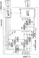
図1は、本発明の第1の実施の形態に係る画像表示装置5の構成例を示している。この画像表示装置5は、入力画像を表すR,G,Bの映像信号(原信号Rorg,Gorg,Borg)が入力される表示制御部4を備えている。また、この表示制御部4によって制御され、フィールドシーケンシャル方式によってカラー画像表示を行う表示パネル2およびバックライト3を備えている。
<1. First Embodiment>
[Overall Configuration of Image Display Device 5]
FIG. 1 shows a configuration example of an
表示パネル2は、バックライト3の各色光の発光に同期して画像表示を行うものである。表示パネル2は、表示制御部4の制御に基づく表示順序に従って、フィールドシーケンシャル方式により複数のフィールド画像を時分割表示するようになっている。表示パネル2は、例えばバックライト3から照射(射出)された光の通過を液晶分子によってコントロールすることによって画像表示を行う透過型の液晶パネルからなる。このような液晶パネルでは、バックライト3から照射された色光を映像信号に基づいて変調するようになっている。なお、表示パネル2の表示面には、規則的に複数の表示画素(図示せず)が2次元配列されている。
The
バックライト3は、カラー画像表示に必要な複数種類の色光を各色光ごとに時分割で発光させることが可能な光源部となっている。バックライト3は、表示制御部4による制御の下に、入力される映像信号に応じて発光駆動が行なわれる。バックライト3は、例えば表示パネル2の背面側に配置されて表示パネル2を照射するようになっている。バックライト3は、発光素子(光源)として例えばLED(Light Emitting Diode;発光ダイオード)を用いて構成することができる。バックライト3は、例えば複数のLEDを2次元的に平面配置することによって複数色を独立して面状発光可能に構成されている。ただし、発光素子としてはLEDに限られるものではない。バックライト3は、例えば少なくとも、赤色光を発する赤色LED、緑色光を発する緑色LEDおよび青色光を発する青色LEDの組み合わせによって構成されている。そして、表示制御部4による制御の下に、各色のLEDが独立して発光(点灯)することによって原色発光するとともに、各色光の加法混色によって無彩色(白黒)発光や補色発光する。ここに、無彩色とは、色の三属性である色相・明度・彩度のうち明度だけをもつ黒・灰・白をいう。バックライト3は、例えば青色LEDを消灯し、赤色LEDと緑色LEDとを発光することによって補色の1つである黄色の発光を行うことができる。また、各色のLEDの発光量を適宜調節して適切な色バランスで同時発光することによって補色や白色以外の任意の色での発光を行うこともできる。
The
このバックライト3はまた、例えば図2に示したように、互いに独立して制御可能であると共に複数の色光を個別に射出可能であるように構成された複数の部分発光領域36を有している。すなわち、このバックライト3は、部分駆動方式のバックライトで構成されている。具体的には、バックライト3は、複数の光源が2次元的に配列されることにより複数の部分発光領域36を有している。これにより、光源部3は、面内方向に発光領域が縦n×横m=K個(n,m=2以上の整数)に分割されている。なお、この分割数は、表示画素よりも低解像度のものとなっている。また、表示パネル2には、各部分発光領域36に対応する複数の部分照射領域26が形成されるようになっている。光源部3は、入力映像信号(原信号Rorg,Gorg,Borg)に応じて、部分発光領域36ごとに独立した発光制御が可能とされている。ここでは、光源は、赤色光を発する赤色LED3R、緑色光を発する緑色LED3G、および青色光を発する青色LED3Bの各色のLEDを組み合わせて構成され、各色光を加法混色することで複数の色光を発光するようになっている。部分発光領域36には、このような光源が少なくとも1つ配置されている。
The
[表示制御部4の詳細構成]
表示制御部4は、R,G,Bの映像信号で表される入力画像をフレーム単位で複数のフィールド画像に分解すると共に、これらの複数のフィールド画像がフィールドシーケンシャル方式により時分割表示されるように、表示制御を行うものである。具体的には、このような表示制御を、バックライト3の各部分発光領域36および表示パネル2に対して行うようになっている。この表示制御部4は、部分駆動化処理部40と、共通最小値抽出部44と、減算部45R,45G,45Bと、出力信号選択スイッチャ46と、バックライト色光選択スイッチャ47とを有している。
[Detailed Configuration of Display Control Unit 4]
The display control unit 4 decomposes the input image represented by the R, G, and B video signals into a plurality of field images in units of frames, and the plurality of field images are time-divisionally displayed by a field sequential method. In addition, display control is performed. Specifically, such display control is performed on each partial
ここで、本実施の形態において、バックライト3が本発明における「光源部」の一具体例に対応し、部分発光領域36が本発明における「部分発光部」の一具体例に対応する。共通最小値抽出部44が、本発明における「信号解析部」の一具体例に対応する。減算部45R,45G,45Bおよび出力信号選択スイッチャ46が、本発明における「信号出力部」の一具体例に対応する。バックライト色光選択スイッチャ47が、本発明における「色光選択部」の一具体例に対応する。
Here, in the present embodiment, the
部分駆動化処理部40は、入力映像信号(原信号Rorg,Gorg,Borg)に対して以下説明する所定の部分駆動化処理を行うことにより、原色成分ごとの部分駆動信号R,G,Bを生成するものである。この部分駆動化処理部40は、低解像度化処理部41と、拡散部42R,42G,42Bと、除算部43R,43G,43Bとを有している。
The partial
低解像度化処理部41は、原信号Rorg,Gorg,Borgに対してそれぞれ所定の低解像度化処理を行うことにより、バックライト3における部分発光領域36単位での発光パターンBLr,BLg,BLbを生成するものである。この発光パターンBLr,BLg,BLbのレベルは、表示パネル2における表示画素ごとの原信号Rorg,Gorg,Borgに対し、部分照射領域26(部分発光領域36)ごとにその領域の信号レベルを解析することにより得られたものである。具体的には、例えば、その領域における最大値などを所定のルールを用いて求めることにより得られたものである。このルールは、発光輝度決定アルゴリズムに属する技術であり、本願とは直接の関連がないため、ここでは説明を省略する。
The resolution
拡散部42R,42G,42Bは、低解像度化処理部41から出力される発光パターンBLr,BLg,BLbに対してそれぞれ所定の拡散処理を行い、拡散処理後の発光パターンBLr,BLg,BLbを除算部43R,43G,43Bへ出力するものである。
The
除算部43R,43G,43Bは、原信号Rorg,Gorg,Borgの信号レベルを、拡散部42R,42G,42Bから出力される拡散処理後の発光パターンBLr,BLg,BLbの信号レベルで除算し、部分駆動用映像信号R,G,Bを生成するものである。具体的には、除算部43R,43G,43Bは、それぞれ、以下の(1)〜(3)式を用いて部分駆動用映像信号R,G,Bを生成するようになっている。
R=(Rorg/BLr) ……(1)
G=(Gorg/BLg) ……(2)
B=(Borg/BLb) ……(3)
The
R = (Rorg / BLr) (1)
G = (Gorg / BLg) (2)
B = (Borg / BLb) (3)
ここで、上記(1)〜(3)式により、原信号=(発光パターン×部分駆動用映像信号)という関係が得られる。このうち、(発光パターン×部分駆動用映像信号)の物理的意味は、ある発光パターンで点灯されたバックライト3における各部分発光領域36の画像イメージに、部分駆動用映像信号の画像イメージを重ね合わせるというものである。これにより、表示パネル2における透過光の明暗分布を相殺し、本来の表示(原信号による表示)を目視することと等価となる。
Here, the relationship of original signal = (light emission pattern × partial drive video signal) is obtained by the above equations (1) to (3). Among these, the physical meaning of (light emission pattern × partial drive video signal) is to superimpose the image image of the partial drive video signal on the image image of each partial
共通最小値抽出部44は、部分駆動用映像信号R,G,Bにより構成される部分駆動用画像における色成分を解析するものである。これにより、この部分駆動用画像から、赤色(R)成分、緑色(G)成分および青色(B)成分の3つの原色成分のうちの少なくとも2つ以上の原色成分に共通な任意の色成分である共通色成分を抽出するようになっている。具体的には、本実施の形態では、部分駆動用画像から3つの原色成分の全てに共通な白色成分(共通白色成分Wcom)を抽出している。
The common minimum
図3(A),(B)は、この共通白色成分Wcomの分離抽出の例を示している。図3(A)では、青色成分の部分駆動用映像信号Bのレベルに合わせて共通白色成分Wcomの分離抽出した例を示し、図3(B)は、赤色成分の部分駆動用映像信号Rのレベルに合わせて共通白色成分Wcomの分離抽出した例を示している。図3(A)の場合、共通白色成分Wcomの分離抽出後の差分画像の成分は、後述する赤色成分ΔRと緑色成分ΔGとなる。図3(B)の場合には、差分画像の成分は、後述する青色成分Bと緑色成分ΔGとなる。すなわち、原信号により構成される原画像の色成分Wを、共通白色成分Wcomと赤色差分ΔR、青色差分ΔB、および緑色差分ΔGとを用いて、以下の(4)式のように表すことができる。
W=Wcom+ΔR+ΔB+ΔG ……(4)
また、各色の輝度比の説明では、SDTVの場合の輝度成分Yの式(以下の(5)式)を考慮して簡易的にし、
Wcom:ΔR:ΔB:ΔG=10:3:1:6
としている。
Y=0.299*R+0.587*G+0.114*B ……(5)
3A and 3B show an example of separation and extraction of the common white component Wcom. 3A shows an example in which the common white component Wcom is separated and extracted in accordance with the level of the blue component partial drive video signal B, and FIG. 3B shows the red component partial drive video signal R. An example in which the common white component Wcom is separated and extracted according to the level is shown. In the case of FIG. 3A, the components of the difference image after the separation and extraction of the common white component Wcom are a red component ΔR and a green component ΔG described later. In the case of FIG. 3B, the components of the difference image are a blue component B and a green component ΔG described later. That is, the color component W of the original image composed of the original signal can be expressed as the following equation (4) using the common white component Wcom, the red difference ΔR, the blue difference ΔB, and the green difference ΔG. it can.
W = Wcom + ΔR + ΔB + ΔG (4)
Further, in the description of the luminance ratio of each color, it is simplified in consideration of the expression of the luminance component Y in the case of SDTV (the following expression (5)),
Wcom: ΔR: ΔB: ΔG = 10: 3: 1: 6
It is said.
Y = 0.299 * R + 0.587 * G + 0.114 * B (5)
減算部45R,45G,45Bは、部分駆動用画像R,G,Bからそれぞれ、フレーム単位で、共通最小値抽出部44により抽出された共通白色成分Wcomを差し引く(減算する)ことにより、差分信号(各原色成分ΔR,ΔG,ΔB)を生成するものである。具体的には、減算部45R,45G,45Bは、それぞれ、以下の(6)〜(8)式を用いて差分信号(各原色成分ΔR,ΔG,ΔB)を生成する。このような各原色成分の差分信号ΔR,ΔG,ΔBにより、各原色光の差分画像(第1の差分画像)が生成されるようになっている。
ΔR=R−Wcom ……(6)
ΔG=G−Wcom ……(7)
ΔB=B−Wcom ……(8)
The
ΔR = R−Wcom (6)
ΔG = G-Wcom (7)
ΔB = B-Wcom (8)
出力信号選択スイッチャ46は、減算部45R,45G,45Bから出力される差分信号ΔR,ΔG,ΔBの画像と、共通最小値抽出部44から出力される共通白色成分Wcomの画像とを、複数のフィールド画像として表示パネル2に選択的に出力するものである。なお、差分信号ΔR,ΔG,ΔBの画像は、本発明における「第1の差分画像」の一具体例に対応し、共通白色成分Wcomの画像は、本発明における「第1の共通色成分画像」の一具体例に対応する。
The output
バックライト色光選択スイッチャ47は、バックライト3における発光色と発光タイミングとを制御するようになっている。具体的には、表示するフィールド画像のタイミング(出力信号選択スイッチャ46の出力タイミング)に同期し、かつフィールド画像に必要とされる色光で適切に発光するよう、バックライト3から射出される色光を選択する発光制御を行うようになっている。より具体的には、バックライト色光選択スイッチャ47は、各原色成分の差分信号ΔR,ΔG,ΔBの画像が選択出力されるフィールド期間(第1のフィールド期間)では、対応する各原色光(赤色光、緑色光または青色光)のみが射出されるように、発光制御する。一方、共通白色成分Wcomの画像が選択出力されるフィールド期間(第2のフィールド期間)では、この共通白色成分Wcomを構成する3つの原色光(赤色光、緑色光および青色光)がともに(同時に)射出されるように、発光制御する。なお、このような発光制御は、部分駆動化処理部40から出力される発光パターンBLr,BLg,BLbと、共通最小値抽出部44から出力される共通白色成分Wcomの画像パターンとに基づいて行われるようになっている。具体的には、(BLr+BLg+BLb)(後述する(12)式参照)の発光パターンにより、バックライト3における各部分発光領域36が点灯することを意味している。
The backlight color
[画像表示装置5の作用・効果]
次に、画像表示装置5の作用および効果について説明する。
[Operation and effect of image display device 5]
Next, the operation and effect of the
(基本動作)
この画像表示装置5では、図1および図2に示したように、バックライト3から部分発光領域36単位で射出された色光が、表示パネル2において変調されることにより、入力映像信号(原信号Rorg,Gorg,Borg)に基づく画像表示が行われる。具体的には、例えば図4に示したように、バックライト3の各部分発光領域36による発光面イメージ71と、表示パネル2単独によるパネル面イメージ72とを物理的に重ね合わせた(掛け算的に合成した)合成イメージ73が、最終的に観察される映像となる。
(basic action)
In this
このとき、表示制御部4では、入力画像がフレーム単位で複数のフィールド画像に分解されてフィールドシーケンシャル方式により時分割表示されるように、バックライト3の各部分発光領域36および表示パネル2に対する表示制御を行う。すなわち、それら複数のフィールド画像を時順次で表示し、人間の目の時間分解能を利用してそれぞれの画面をそれと認識できない速さで切り替える。これにより、目の時間方向の積分効果による時間混色によって各色光を弁別不能にし、時間混色によるカラー画像表示がなされる。
At this time, the display control unit 4 displays the display on each partial
(色割れ低減動作)
ところで、前述した従来のフィールドシーケンシャル方式では、上記のように、人間の目の時間分解能を利用してそれぞれの画面をそれと認識できない速さで切り替えることを表示の基本原理としている。しかしながら、時間の経過順に順次表示されるRGBの画像が、眼球の視神経上の制約、および人間の脳の画像認識の感覚などの複雑な要因でうまく混ざり合わない。その結果、時に、白などの色純度の低い画像表示時や、その表示体の画面内の移動表示を追随視する場合などに、各原色の画像が残像等として視認され、著しい不快感を観察者に与える色割れ(カラーブレーキング)という表示現象を発生させる。なお、このような色割れ現象には、前述したように、静止画表示時の色割れ現象と、動画追従視時の色割れ現象との2種類に大別されるが、以下説明する本実施の形態の表示方法では、これらの2種類の色割れ現象のいずれに対しても低減効果がある。
(Color break-up reduction operation)
By the way, in the above-mentioned conventional field sequential system, as described above, the basic principle of display is to switch each screen at a speed at which it cannot be recognized using the time resolution of the human eye. However, RGB images that are sequentially displayed in the order of passage of time do not mix well due to complicated factors such as restrictions on the optic nerve of the eyeball and the sense of image recognition of the human brain. As a result, when displaying images with low color purity such as white, or when following the moving display of the display body in the screen, the images of each primary color are visually recognized as afterimages, and significant discomfort is observed. Display phenomenon of color breakage (color breaking). In addition, as described above, such a color breakup phenomenon is roughly divided into two types: a color breakup phenomenon during still image display and a color breakup phenomenon during moving image following viewing. In the display method of this form, there is a reduction effect for both of these two types of color breakup phenomena.
そこで、本実施の形態では、表示制御部4における表示制御により、図1および図5に示したようにして、表示動作を行う。すなわち、まず、部分駆動化処理部40内の低解像度化処理部41において、原信号Rorg,Gorg,Borgに対して低解像度化処理を行うことにより、バックライト3における部分発光領域36部単位での発光パターンBLr,BLg,BLbを生成する。また、部分駆動化処理部40内の除算部43R,43G,43Bにおいて、原信号Rorg,Gorg,Borgにおける信号レベルをこれらの発光パターンBLr,BLg,BLbの信号レベルで除算することにより、部分駆動用映像信号R,G,Bを生成する。
Therefore, in the present embodiment, the display operation is performed as shown in FIGS. 1 and 5 by the display control in the display control unit 4. That is, first, in the resolution
次いで、共通最小値抽出部44では、部分駆動用映像信号R,G,Bにより構成される部分駆動用画像における色成分を解析し、この部分駆動用画像から、3つの原色成分の全てに共通な白色成分である共通白色成分Wcomを抽出する。
Next, the common minimum
続いて、減算部45R,45G,45Bでは、部分駆動用映像信号R,G,Bからフレーム単位で共通白色成分Wcomを差し引く(減算する)ことにより、差分信号(各原色成分ΔR,ΔG,ΔB)を生成する。そして、出力信号選択スイッチャ46では、これら各原色成分の差分信号ΔR,ΔG,ΔBの画像と、共通白色成分Wcomの画像とを、複数のフィールド画像として表示パネル2に選択的に出力する。これにより、図5に示したように、表示パネル2単独によるパネル面イメージ72(差分信号ΔR,ΔG,ΔBの画像および共通白色成分Wcomの画像)が生成される。
Subsequently, the
一方、バックライト色光選択スイッチャ47では、発光パターンBLr,BLg,BLbと共通白色成分Wcomの画像パターンとに基づき、出力信号選択スイッチャ46の出力タイミングに同期して、バックライト3から射出される色光を選択する発光制御を行う。具体的には、図5に示したように、各原色成分の差分信号ΔR,ΔG,ΔBの画像が選択出力されるフィールド期間では、対応する各原色光(赤色光、緑色光または青色光)のみが射出されるように、発光制御する。すなわち、差分信号ΔRの画像が出力されるフィールド期間では、赤色成分の発光パターンBLrを用いて赤色光の単色発光がなされるように、発光制御する。同様に、差分信号ΔGの画像が出力されるフィールド期間では、緑色成分の発光パターンBLgを用いて緑色光の単色発光がなされるように、発光制御する。また、差分信号ΔBの画像が出力されるフィールド期間では、青色成分の発光パターンBLbを用いて青色光の単色発光がなされるように、発光制御する。一方、共通白色成分Wcomの画像が選択出力されるフィールド期間では、この共通白色成分Wcomを構成する3つの原色光(赤色光、緑色光および青色光)がともに(同時に)射出されるように、発光制御する。すなわち、このフィールド期間では、共通白色成分Wcomの画像パターンに基づく3原色成分の発光パターンBLrgbを用いて、3原色がともに発光されるように、発光制御する。
On the other hand, in the backlight color
ここで、前述の(1)〜(4),(6)〜(8)式を用いて、以下の(9)〜(12)式が導かれるため、以下のことが言える。すなわち、まず、各原色成分の差分信号ΔR,ΔG,ΔBの画像が選択出力されるフィールド期間では、フィールド映像73ΔR,73ΔG,73ΔB((12)式中の{(ΔR×BLr)+(ΔG×BLg)+(ΔB×BLb)}に対応)が得られる。また、共通白色成分Wcomの画像が選択出力されるフィールド期間では、フィールド映像73Wcom((12)式中の{Wcom×(BLr+BLg+BLb)}に対応)が得られる。したがって、(12)式により、原画と復元画(目視画)とは、原理的には等しくなる。
Rorg=R×BLr=(ΔR+Wcom)×BLr ……(9)
Gorg=G×BLg=(ΔG+Wcom)×BLg ……(10)
Borg=B×BLb=(ΔB+Wcom)×BLb ……(11)
原画=Rorg+Gorg+Borg
=(R×BLr)+(G×BLg)+(B×BLb)
={(ΔR×BLr)+(ΔG×BLg)+(ΔB×BLb)}
+{Wcom×(BLr+BLg+BLb)}
≒復元画(目視画) ……(12)
Here, since the following formulas (9) to (12) are derived using the above-described formulas (1) to (4) and (6) to (8), the following can be said. That is, first, in the field period in which the images of the difference signals ΔR, ΔG, ΔB of the respective primary color components are selectively output, the field images 73ΔR, 73ΔG, 73ΔB ({(ΔR × BLr) + (ΔG × BLg) + (ΔB × BLb)}). In the field period in which an image of the common white component Wcom is selected and output, a field video 73Wcom (corresponding to {Wcom × (BLr + BLg + BLb)} in the equation (12)) is obtained. Therefore, according to the equation (12), the original image and the restored image (viewed image) are theoretically equal.
Rorg = R × BLr = (ΔR + Wcom) × BLr (9)
Gorg = G × BLg = (ΔG + Wcom) × BLg (10)
Borg = B × BLb = (ΔB + Wcom) × BLb (11)
Original picture = Rorg + Gorg + Borg
= (R × BLr) + (G × BLg) + (B × BLb)
= {(ΔR × BLr) + (ΔG × BLg) + (ΔB × BLb)}
+ {Wcom × (BLr + BLg + BLb)}
≒ Restored image (visual image) ...... (12)
このようにして、画像表示装置5では、共通白色成分Wcomの画像が選択出力されるフィールド期間において、複数(ここでは3つ)の原色光がともに射出されて多原色表示(3色表示)がなされる。また、これらの原色光はいずれも、表示画素よりも低解像度である部分発光領域36単位でバックライト3から射出される。これにより、この共通白色成分Wcomの画像が選択出力されるフィールド期間では、低色解像度の多原色表示が行われる。
In this way, in the
一方、各原色成分の差分信号ΔR,ΔG,ΔBの画像が選択出力されるフィールド期間では、部分駆動用画像R,G,Bから共通白色成分Wcomを差し引いてなる差分信号ΔR,ΔG,ΔBの画像が、各原色成分単位で選択出力される。また、このフィールド期間では、それぞれに対応する原色光のみがバックライト3から射出される。これにより、1フレーム期間内での時間軸に沿った表示画像の輝度分布が、上記した共通白色成分Wcomの画像が選択出力されるフィールド期間に集中し易くなる(偏り易くなる)。
On the other hand, in the field period in which the images of the difference signals ΔR, ΔG, ΔB of the respective primary color components are selectively output, the difference signals ΔR, ΔG, ΔB obtained by subtracting the common white component Wcom from the partial drive images R, G, B. An image is selectively output for each primary color component unit. In this field period, only the primary color light corresponding to each is emitted from the
以上のように本実施の形態では、共通白色成分Wcomの画像が選択出力されるフィールド期間において、3つの原色光がともに射出されて多原色表示がなされると共に、これらの原色光がいずれも、表示画素よりも低解像度である部分発光領域36単位でバックライト3から射出されるようにしたので、この共通白色成分Wcomの画像が選択出力されるフィールド期間において、低色解像度の多原色表示(3色表示)を行うことができる。また、各原色成分の差分信号ΔR,ΔG,ΔBの画像が選択出力されるフィールド期間において、差分信号ΔR,ΔG,ΔBの画像が各原色成分単位で選択出力されると共に、それぞれに対応する原色光のみがバックライト3から射出されるようにしたので、1フレーム期間内での時間軸に沿った表示画像の輝度分布を、共通白色成分Wcomの画像が選択出力されるフィールド期間に集中させる(偏らせる)ことができる。よって、フィールドシーケンシャル方式における色割れの発生を抑制することが可能となり、カラー表示の際の画質を向上させることができる。
As described above, in the present embodiment, in the field period in which the image of the common white component Wcom is selected and output, the three primary color lights are emitted together to display multi-primary colors, and all of these primary color lights are Since the light is emitted from the
<2.第2の実施の形態>
次に、本発明の第2の実施の形態について説明する。本実施の形態では、共通色成分として、上記実施の形態の共通白色成分Wcomの代わりに、以下説明する共通黄色成分Yecomを用いるようにしたものである。なお、上記第1の実施の形態における構成要素と同一のものには同一の符号を付し、適宜説明を省略する。
<2. Second Embodiment>
Next, a second embodiment of the present invention will be described. In the present embodiment, the common yellow component Yecom described below is used as the common color component instead of the common white component Wcom of the above embodiment. In addition, the same code | symbol is attached | subjected to the same component as the said 1st Embodiment, and description is abbreviate | omitted suitably.
[画像表示装置5Aの全体構成]
図6は、本実施の形態に係る画像表示装置5Aの構成例を示している。この画像表示装置5Aは、第1の実施の形態の画像表示装置5において、表示制御部4の代わりに表示制御部4Aを備えたものである。表示制御部4Aは、共通最小値抽出部44、出力信号選択スイッチャ46およびバックライト色光選択スイッチャ47の代わりに、共通最小値抽出部44A、出力信号選択スイッチャ46Aおよびバックライト色光選択スイッチャ47Aを有している。また、表示制御部4とは異なり、青色成分に対応する減算部45Bが設けられていない。
[Overall Configuration of Image Display Device 5A]
FIG. 6 shows a configuration example of the image display device 5A according to the present embodiment. This image display device 5A includes the display control unit 4A in place of the display control unit 4 in the
共通最小値抽出部44Aは、部分駆動用映像信号R,G,Bから、赤色成分および緑色成分に共通な色成分である黄色成分(共通黄色成分Yecom)を抽出するものである。ここで、原信号により構成される原画像の色成分Wを、共通黄色成分Yecomと赤色差分ΔR、青色差分ΔB、および緑色差分ΔGとを用いて、以下の(13)式のように表すことができる。
W=Yecom+ΔR+ΔB+ΔG ……(13)
また、各色の輝度比は、前述のSDTVの場合の輝度成分Yの式を考慮して、概ね、
Yecom:ΔR:ΔB:ΔG=9:3:1:6
としている。
The common minimum
W = Yecom + ΔR + ΔB + ΔG (13)
In addition, the luminance ratio of each color is approximately determined in consideration of the expression of the luminance component Y in the case of the SDTV described above.
Yecom: ΔR: ΔB: ΔG = 9: 3: 1: 6
It is said.
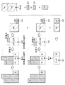
図7は、R,G,Bのカラー信号から共通黄色成分Yecomを抽出する第1の方法を模式的に示している。図7には、信号レベルがG,R,Bの順に低くなっている第1の信号構成例での抽出例(図の上段)と、信号レベルがR,G,Bの順に低くなっている第2の信号構成例での抽出例とを同時に示している。この第1の方法では、まず、1次共通ミニマム成分として白色成分Wminを抽出する(R1,G1,B1)。次に、この白色成分Wminのうち、R1,G1を第1の黄色成分Ye1と青色成分B1とに分離する。また、白色成分Wminを抽出した後の1次差分成分(ΔR1,ΔG1)の2次共通ミニマム成分として第2の黄色成分Ye2を抽出する。そして、抽出された第1の黄色成分Ye1と第2の黄色成分Ye2とを合算して、最終的な共通黄色成分Yecomとする。第2の黄色成分Ye2を抽出した後には、2次差分成分(ΔG2またはΔR2)が残る。従って、図の上段の第1の信号構成例では最終的に共通黄色成分Yecomと緑色および青色の残成分からなる「Yecom+ΔG+ΔB」に分離される。また、第2の信号構成例では最終的に共通黄色成分Yecomと赤色および青色の残成分からなる「Yecom+ΔR+ΔB」に分離される。 FIG. 7 schematically shows a first method for extracting the common yellow component Yecom from the R, G, B color signals. FIG. 7 shows an example of extraction in the first signal configuration example in which the signal level decreases in the order of G, R, and B (upper part of the figure), and the signal level decreases in the order of R, G, and B. The extraction example in the 2nd signal structure example is shown simultaneously. In the first method, first, a white component Wmin is extracted as a primary common minimum component (R1, G1, B1). Next, among the white component Wmin, R1 and G1 are separated into a first yellow component Ye1 and a blue component B1. Further, the second yellow component Ye2 is extracted as the secondary common minimum component of the primary difference components (ΔR1, ΔG1) after extracting the white component Wmin. Then, the extracted first yellow component Ye1 and second yellow component Ye2 are added together to obtain a final common yellow component Yecom. After extracting the second yellow component Ye2, the secondary difference component (ΔG2 or ΔR2) remains. Therefore, in the first signal configuration example in the upper part of the figure, the signal is finally separated into “Yecom + ΔG + ΔB” composed of the common yellow component Yecom and the remaining components of green and blue. In the second signal configuration example, the signal is finally separated into “Yecom + ΔR + ΔB” composed of the common yellow component Yecom and the red and blue remaining components.
図8は、R,G,Bのカラー信号から共通黄色成分Yecomを抽出する第2の方法を模式的に示している。図7の第1の方法では、一旦、白色成分Wminを抽出した後に黄色成分を抽出するようにしたが、この第2の方法では白色成分Wminを抽出することなく直接的に共通黄色成分Yecomを抽出する。この第2の方法では、共通黄色成分Yecomを抽出した後の1次差分がそのまま、最終的な残成分となる。最終的に得られる成分は、図7の場合と同様である。 FIG. 8 schematically shows a second method of extracting the common yellow component Yecom from the R, G, B color signals. In the first method of FIG. 7, the yellow component is extracted after extracting the white component Wmin. However, in the second method, the common yellow component Yecom is directly extracted without extracting the white component Wmin. Extract. In the second method, the primary difference after extracting the common yellow component Yecom is used as it is as the final remaining component. The components finally obtained are the same as in FIG.
出力信号選択スイッチャ46Aは、減算部45R,45Gからの差分信号ΔR,ΔGの画像と、除算部43Bからの部分駆動用映像信号Bの画像と、共通黄色成分Yecomの画像とを、複数のフィールド画像として表示パネル2に選択的に出力するものである。
The output
バックライト色光選択スイッチャ47Aは、2つの原色成分の差分信号ΔR,ΔGの画像と部分駆動用映像信号Bの画像とが選択出力されるフィールド期間では、対応する各原色光(赤色光、緑色光または青色光)のみが射出されるように、発光制御する。一方、共通黄色成分Yecomの画像が選択出力されるフィールド期間では、この共通黄色成分Yecomを構成する2つの原色光(赤色光および緑色光)がともに(同時に)射出されるように、発光制御する。
The backlight color
[画像表示装置5Aの作用・効果]
次に、画像表示装置5Aの作用および効果について説明する。なお、画像表示装置5Aの基本動作は、第1の実施の形態の画像表示装置5と同様であるため、説明を省略する。
[Operation / Effect of Image Display Device 5A]
Next, the operation and effect of the image display device 5A will be described. The basic operation of the image display device 5A is the same as that of the
(色割れ低減動作)
この画像表示装置5Aでは、図9に示したように、共通黄色成分Yecomの画像が選択出力されるフィールド期間において、2つの原色光(赤色光および緑色光)がともに射出されて多原色表示(2色表示)がなされる。また、これらの原色光はいずれも、表示画素よりも低解像度である部分発光領域36単位でバックライト3から射出される。これにより、この共通黄色成分Yecomの画像が選択出力されるフィールド期間では、低色解像度の多原色表示が行われる。
(Color break-up reduction operation)
In this image display device 5A, as shown in FIG. 9, in the field period in which an image of the common yellow component Yecom is selected and output, two primary color lights (red light and green light) are emitted together to display multiple primary colors ( (2-color display) is made. In addition, all of these primary color lights are emitted from the
一方、差分信号ΔR,ΔGの画像と部分駆動用映像信号Bの画像とが選択出力されるフィールド期間では、部分駆動用画像R,Gから共通黄色成分Yecomを差し引いてなる差分信号ΔR,ΔGの画像と、部分駆動用映像信号Bの画像とが、選択出力される。また、このフィールド期間では、それぞれに対応する原色光のみがバックライト3から射出される。これにより、1フレーム期間内での時間軸に沿った表示画像の輝度分布が、上記した共通黄色成分Yecomの画像が選択出力されるフィールド期間に集中し易くなる(偏り易くなる)。
On the other hand, in the field period in which the images of the difference signals ΔR and ΔG and the image of the partial drive video signal B are selectively output, the difference signals ΔR and ΔG obtained by subtracting the common yellow component Yecom from the partial drive images R and G. The image and the image of the partial drive video signal B are selectively output. In this field period, only the primary color light corresponding to each is emitted from the
これにより、本実施の形態においても、第1の実施の形態と同様の作用により、同様の効果を得ることが可能である。すなわち、フィールドシーケンシャル方式における色割れの発生を抑制することが可能となり、カラー表示の際の画質を向上させることができる。 Thereby, also in this Embodiment, it is possible to acquire the same effect by the effect | action similar to 1st Embodiment. That is, the occurrence of color breakup in the field sequential method can be suppressed, and the image quality in color display can be improved.
また、本実施の形態では、上記第1の実施の形態とは異なり、共通白色成分Wcomの代わりに共通黄色成分Yecomを用いるようにしたので、以下説明するように、共通黄色成分Yecomのほうが共通白色成分Wcomよりも色割れ低減効果が大きいと言える。これは、公知文献(O Plus E、1985年5月号、No.66、東京工芸大学工学部 畑田 豊彦、生理光学10 動画像と視覚特性、P82、図86)を基に考察したものである。すなわち、まず、同文献の図86(b)により、輝度がより明るく、呈示時間が短いと、より明るく感じられるという視覚特性がある。また、同図(c)により、見掛けの光の明るさがピークになる時間に、色による順序があることが示されている。そして、それが、赤色→緑色といった順であることから、黄色はその間であろうことが推察されると共に、黄色の輝度は他の単色よりも高いため、輝度的に同図(b)の更に明るく見える特性も備えていると考えられる。したがって、黄色では、RGBの3原色を全て混ぜた白色よりも先(高速)に知覚されやすい性質が有ると考えられる。このため、白色をベースとした画像(白色共通成分Wcomの画像)を基準とするよりも、黄色をベースとした画像(共通黄色成分Yecomの画像)を基準としたほうが、移動する動画の色に対する知覚感度が総じて高く、色割れしにくいと推察することができる。
In the present embodiment, unlike the first embodiment, the common yellow component Yecom is used instead of the common white component Wcom. Therefore, as described below, the common yellow component Yecom is more common. It can be said that the effect of reducing color breakage is greater than that of the white component Wcom. This is based on known literature (O Plus E, May 1985, No. 66, Toyohiko Hatada, Faculty of Engineering, Tokyo Polytechnic University,
なお、本実施の形態では、3つの原色成分のうちの2つの原色成分に共通な任意の色成分として、赤色成分および緑色成分に共通な色成分である黄色成分(共通黄色成分Yecomを用いたが、この場合には限られない。すなわち、例えば、図7および図8の例と同様にして、他の補色(マゼンタ成分Mg、シアン成分Cy)も容易に共通色成分(共通補色成分)として分離することが可能である。したがって、2つの原色成分に共通な任意の色成分として、緑色成分および青色成分に共通なシアン成分であったり、青色成分および赤色成分に共通なマゼンダ成分であったりしてもよい。これらの場合、色光選択部は、そのような共通色成分の画像が選択的に出力されるフィールド期間において、緑色光および青色光、あるいは、青色光および赤色光がともに射出されるように、バックライト3から射出される色光を選択するようにすればよい。
In this embodiment, as an arbitrary color component common to two primary color components among the three primary color components, a yellow component (common yellow component Yecom) which is a color component common to the red component and the green component is used. However, the present invention is not limited to this case, that is, other complementary colors (magenta component Mg, cyan component Cy) can be easily used as common color components (common complementary color components), for example, in the same manner as in the examples of FIGS. Therefore, as an arbitrary color component common to the two primary color components, it may be a cyan component common to the green component and the blue component, or a magenta component common to the blue component and the red component. In these cases, the color light selection unit may select the green light and the blue light, or the blue light and the blue light in the field period in which the image of the common color component is selectively output. As the red light are both emitted, it is sufficient to select the color light emitted from the
(第2の実施の形態の変形例:変形例1)
図10は、第2の実施の形態の変形例(変形例1)に係る画像表示装置5Bの構成例を示している。この画像表示装置5Bは、第2の実施の形態の画像表示装置5Aにおいて、表示制御部4Aの代わりに表示制御部4Bを備えたものである。表示制御部4Bは、部分駆動化処理部40および出力信号選択スイッチャ46Aの代わりに、部分駆動化処理部40Bおよび出力信号選択スイッチャ46Bを有している。
(Modification of the second embodiment: Modification 1)
FIG. 10 shows a configuration example of an image display device 5B according to a modification (Modification 1) of the second embodiment. This image display device 5B includes the display control unit 4B instead of the display control unit 4A in the image display device 5A of the second embodiment. The display control unit 4B includes a partial
部分駆動化処理部40Bは、部分駆動化処理部40において、低解像度化処理部41の代わりに低解像度化処理部41Bを設けると共に、原信号Borgに対応する拡散部42Bおよび除算部43Bを設けないようにしたものである。すなわち、原信号Borgにより構成される青色成分の原画像が選択出力されるフィールド期間では、バックライト3における全ての部分発光領域36を一括して発光制御し、これまで説明したような部分発光領域36単位での部分発光制御を行わないようにする。したがって、低解像度化処理部41Bは、青色成分に対応する発光パターンBLb=1の固定値として出力するようになっている。
In the partial
なお、出力信号選択スイッチャ46Bは、減算部45R,45Gからの差分信号ΔR,ΔGの画像と、原信号Borgにより構成される原画像と、共通黄色成分Yecomの画像とを、複数のフィールド画像として表示パネル2に選択的に出力するものである。
Note that the output
このようにして、本変形例のように、共通色成分以外の他の原色成分については、部分発光領域36単位での部分発光制御を行わないようにしてもよい。
In this way, as in the present modification, the partial light emission control in units of the partial
<3.第3の実施の形態>
次に、本発明の第3の実施の形態について説明する。本実施の形態では、上記第1,第2の実施の形態で説明した表示制御手法に加えて、さらに、表示制御部において、複数のフィールド画像の1フレーム期間内での表示順序を、フレーム単位で可変制御するようにしたものである。なお、上記第1,第2の実施の形態における構成要素と同一のものには同一の符号を付し、適宜説明を省略する。
<3. Third Embodiment>
Next, a third embodiment of the present invention will be described. In the present embodiment, in addition to the display control methods described in the first and second embodiments, the display control unit further changes the display order of a plurality of field images within one frame period in units of frames. It is designed to be variably controlled with. In addition, the same code | symbol is attached | subjected to the same component as the said 1st, 2nd embodiment, and description is abbreviate | omitted suitably.
[画像表示装置5Cの全体構成]
図11は、本実施の形態に係る画像表示装置5Cの構成例を示している。この画像表示装置5Cは、第1の実施の形態の画像表示装置5において、表示制御部4の代わりに表示制御部1を備えたものである。
[Overall Configuration of Image Display Device 5C]
FIG. 11 shows a configuration example of an image display device 5C according to the present embodiment. This image display device 5C includes the
[表示制御部1の詳細構成]
表示制御部1は、R,G,Bの映像信号で表される入力画像をフレーム単位で複数のフィールド画像に分解すると共に、複数のフィールド画像の1フレーム期間内での表示順序をフレーム単位で可変制御することが可能となっている。表示制御部1は、第1の実施の形態で説明した部分駆動化処理部40と、信号輝度解析処理部11と、輝度最大成分抽出部12と、出力順序決定部13と、比視感度曲線補正部14と、選択部15とを有している。この表示制御部1はまた、信号演算処理部16と、信号レベル処理部17と、出力信号選択スイッチャ18と、バックライト色光選択スイッチャ19とを有している。
[Detailed Configuration of Display Control Unit 1]
The
ここで、本実施の形態において、信号輝度解析処理部11が、本発明における「信号解析部」の一具体例に対応する。信号輝度解析処理部11および輝度最大成分抽出部12が、本発明における「基準画像決定部」の一具体例に対応する。信号演算処理部16、信号レベル処理部17および出力信号選択スイッチャ18が、本発明における「信号出力部」の一具体例に対応する。出力順序決定部13が、本発明における「出力順序決定部」の一具体例に対応する。
Here, in the present embodiment, the signal luminance
信号輝度解析処理部11は、フレーム単位で入力画像(原信号Rorg,Gorg,Borg)の色成分を解析し、入力画像を複数の色成分画像に分解した場合の各色成分画像の信号レベルを求めるようになっている。ここで分解される色成分画像の種類については後に詳述するが、信号輝度解析処理部11は、複数の色成分画像として赤色成分、緑色成分、および青色成分の原色画像のみに分解した場合の各原色画像の信号レベルを求めるようになっている。さらに、その他の任意の色成分を抽出した場合の他の色成分画像の信号レベルを求めるようになっている。具体例は後述するが、例えば、他の色成分画像の信号レベルとして、入力画像から白色成分(共通白色成分Wcom)を抽出した場合の白色成分の信号レベルを求めるようになっている。
The signal luminance
信号輝度解析処理部11はまた、求められた各色成分画像の信号レベルに基づいて、各色成分画像ごとに、視感度特性を加味した輝度レベルを算出するようになっている。
The signal luminance
輝度最大成分抽出部12は、信号輝度解析処理部11での解析結果に基づいて、最も輝度レベルの高い色成分画像または2番目に輝度レベルの高い色成分画像を基準画像(後述する中心画像)として決定するようになっている。この基準画像としては、例えば表示パネル2において1フレーム分の画像を表示したときに、観察者の網膜上での合成輝度分布が中央部で輝度が高く周辺部で輝度が低くなり、かつ合成輝度分布の広がりの幅ができるだけ少なくなるような色成分画像を選ぶとよい。
Based on the analysis result of the signal luminance
信号輝度解析処理部11および輝度最大成分抽出部12は、複数の輝度変換式の中から指定された所定の輝度変換式を選択的に用いて、輝度レベルの算出を行うようになっている。例えばSDTVでは、輝度成分Yは以下の(14)式で表される(*は乗算記号)。なお、厳密には各種規格による種々の変換式があるが、本実施の形態では説明を分かりやすくするため、平易なものを使用する。これは、R,G,Bの各原色信号に、標準的な視感度特性を加味した輝度変換式となっている。標準的な視感度特性を加味した場合、R,G,Bの各原色信号は輝度比率がおおよそ、R:G:B=0.3:0.6:0.1となるように変換される。
Y=0.299*R+0.587*G+0.114*B ……(14)
The signal luminance
Y = 0.299 * R + 0.587 * G + 0.114 * B (14)
この輝度変換式としては、例えば視聴環境(明るい環境であるか暗い環境であるか)に応じた複数の輝度変換式を選択的に使ってもよい。例えば視聴環境に応じて、輝度変換式として少なくとも明所視と暗所視とに応じた2種類の輝度変換式を選択的に用いるようにしてもよい。また、観察者(視聴者)の視覚的な個人差に応じた複数の輝度変換式を選択的に使ってもよい。例えば少なくとも正常視覚者用の輝度変換式と色覚異常者用の輝度変換式との2種類の輝度変換式とを選択的に用いるようにしてもよい。これらの輝度変換式は、選択部15を介して視聴者の好みに応じて視聴環境や色弱等の色覚異常の有無が指定された場合に、適宜変更可能となっている。なお、視聴環境に応じた輝度変換式を選択する場合には、例えば明るさセンサによって環境の明るさを自動的に検出し、その検出結果に応じて最適な輝度変換式を自動的に選択するようにしてもよい。比視感度曲線補正部14は、選択部15からの指定に応じた輝度変換式を選択させるよう、信号輝度解析処理部11および輝度最大成分抽出部12に指示を行う。
As this luminance conversion formula, for example, a plurality of luminance conversion formulas corresponding to the viewing environment (whether the environment is bright or dark) may be selectively used. For example, according to the viewing environment, two types of luminance conversion formulas corresponding to at least photopic vision and scotopic vision may be selectively used as the luminance conversion formula. Further, a plurality of brightness conversion formulas corresponding to the visual individual differences of the observer (viewer) may be selectively used. For example, at least two types of luminance conversion formulas, that is, a luminance conversion formula for a normal viewer and a luminance conversion formula for a color blind person may be selectively used. These luminance conversion formulas can be appropriately changed when the presence or absence of color vision abnormality such as viewing environment and color weakness is designated via the
信号演算処理部16および信号レベル処理部17は、入力画像からフレーム単位で基準画像の色成分を差し引いた差分画像を求めると共に、差分画像を複数の色成分に分解するようになっている。また、分解された各色成分の差分画像を信号値が略半分となるように2つに分割するようになっている。
The signal
出力信号選択スイッチャ18は、それら2つに分割された各色成分の差分画像と基準画像とを複数のフィールド画像として表示パネル2に選択的に出力するようになっている。
The output
バックライト色光選択スイッチャ19は、バックライト3における発光色と発光タイミングとを制御するようになっている。バックライト色光選択スイッチャ19は、表示するフィールド画像のタイミングに同期し、かつフィールド画像に必要とされる色光で適切に発光するよう、バックライト3の発光制御を行うようになっている。
The backlight color
出力順序決定部13は、出力信号選択スイッチャ18を介して表示パネル2に出力する複数のフィールド画像の出力順序を制御するものである。また、出力順序決定部13は、バックライト色光選択スイッチャ19を介してバックライト3の発光色の発光順序を制御する。出力順序決定部13は、1フレーム期間内で時間的な中心位置に基準画像が表示されるように出力順序および発光順序を制御する。また、上記2つに分割された各色成分の差分画像が、視感度特性を加味した輝度レベルの高い順に基準画像に時間的に前後して表示されるように出力順序および発光順序を制御する。なお、視感度特性を加味した輝度レベルは、赤色、緑色および青色を例にすると、標準的な場合には、緑色が最も視感度が高く、青色が最も視感度が低い。
The output
[画像表示装置5Cの作用・効果]
次に、画像表示装置5Cの作用および効果について、従来技術と比較しつつ詳細に説明する。
[Operation / Effect of Image Display Device 5C]
Next, the operation and effect of the image display device 5C will be described in detail in comparison with the prior art.
(従来手法による表示方法)
この画像表示装置の動作(表示方法)について説明する前に、まず、従来技術との比較を行うために、従来技術によるフィールドシーケンシャル方式の表示手法およびその問題点について説明する。なお、以下の説明においては、特別な場合を除き、色覚特性と視聴環境は標準的なモデルを想定して説明する。標準的なモデルとして、観察者は正常色覚者であり、明所視の環境で画像を表示するものとする。
(Display method using the conventional method)
Before describing the operation (display method) of this image display device, first, in order to make a comparison with the prior art, a field sequential display method according to the prior art and its problems will be described. In the following description, except for special cases, the color vision characteristics and the viewing environment are described assuming a standard model. As a standard model, the observer is a normal color vision person and displays an image in a photopic environment.
図12は、フィールドシーケンシャル方式での画像表示の概念を示している。この表示例では、1フレームの画像が複数の色成分画像(フィールド画像)群に分解されている。図12は、1フレーム群の画像が、時間経過と共に、右方向に空間的に移動していく様子を示した時空図となっている。図12では、A,B,C,D・・・のフレーム順に各フレーム画像が表示されている。各フレーム画像は、4つの色のサブフィールドに分割されている。例えばAフレームは、色のサブフィールドA1,A2.A3,A4に分割されたような一群のフレーム単位として構成されている。矢印22は時間経過を示し、矢印23は、空間軸(画表示位置座標軸)を示す。矢印24は、観測者25による観測の中心(視線追従基準)を示すものとする。ところで、この立体的図示による空間的表記は一般的では無く、上方矢印H方向から鳥瞰したような視点の図13のような平面図としての表示が一般的である。以降、図13の表示型式を使用して述べる。
FIG. 12 shows the concept of image display by the field sequential method. In this display example, one frame image is divided into a plurality of color component images (field images). FIG. 12 is a space-time diagram illustrating a state in which an image of one frame group spatially moves to the right as time passes. In FIG. 12, the frame images are displayed in the order of frames A, B, C, D. Each frame image is divided into four color subfields. For example, the A frame includes color subfields A1, A2,. It is configured as a group of frames that are divided into A3 and A4. An
図13は、フィールドシーケンシャル方式によってR,G,Bの3フィールドに分解されたフレーム単位の画像が右方向に移動する様子を示している(図の上段)。各フィールド画像は、1フレームの期間内でR,G,Bの表示順で表示されている。追従視基準軸20は、1フレーム期間内の中央に表示されるGフィールド画像の中心位置にあるものとする。図13にはまた、網膜上で追従視時に重なり合うイメージ(網膜上での輝度分布)を図示してある(図の下段)。図13のような場合、明らかな色割れといわれる色ずれが、移動方向の前後に生じる。すなわち、図13のようなフィールド構成で原画像が白色である画像を右方向に移動させると、図14に示したように、実際に見える画像は左右端部で色が分離して見えてしまう。
FIG. 13 shows a state in which an image in frame units decomposed into three fields of R, G, and B by the field sequential method moves in the right direction (upper part of the figure). Each field image is displayed in the display order of R, G, and B within a period of one frame. The tracking
ところで、図13の下段に示した網膜上での輝度分布の表記は不正確である。そこで、図15に網膜上での輝度分布をより正確に示す。縦軸の単位として“網膜刺激レベル”としてあるが、この網膜刺激レベルは、ほぼ、視感度処理後の輝度に近いとしてよい。ここで、上述したように輝度成分Yは、SDTVの場合は、(14)式で概略表される。このため、図13では、網膜上で全体的に平坦な輝度分布とされているが、視感度特性を考慮すると正確には図15に示したように、左右端部の輝度レベルの分布が異なっている。すなわち、図15に示したように、黄色成分Yeおよび赤色成分Rのずれが知覚される右側の部分32と、青色成分Bおよびシアン成分Cyのずれが知覚される左側の部分31とでは輝度分布が異なる。つまり、輝度のエネルギーが網膜合成画像上で不揃いになり、いびつになる。
By the way, the notation of the luminance distribution on the retina shown in the lower part of FIG. 13 is inaccurate. Therefore, FIG. 15 shows the luminance distribution on the retina more accurately. Although the unit of the vertical axis is “retinal stimulation level”, this retinal stimulation level may be substantially close to the luminance after the visibility processing. Here, as described above, the luminance component Y is schematically represented by the equation (14) in the case of SDTV. For this reason, in FIG. 13, the luminance distribution is generally flat on the retina. However, when the visibility characteristics are taken into account, the distribution of the luminance levels at the right and left ends is different as shown in FIG. ing. That is, as shown in FIG. 15, the luminance distribution in the
図13および図15において、追従視基準軸20,30を視感度特性を考慮した場合の最も輝度の高い緑色成分Gの画像箇所に引いてあることには意味がある。視感度特性を考慮した場合、他の赤色成分Rと青色成分Bの輝度が相対的に低い。目は無意識に最も明るい画像を追いかけるため、追従視基準軸は輝度が相対的に高い箇所に据える必要がある。もし、緑色成分Gが全く存在しない画像においては、次に明るい画像は赤色成分Rであるから、追従視基準軸の位置は赤色成分Rに近くなる。すなわち、どの色を目(脳)が追いかけるかがポイントである。 In FIGS. 13 and 15 , it is meaningful that the follow-up visual reference axes 20 and 30 are drawn to the image portion of the green component G having the highest luminance when the visibility characteristic is considered. When the visibility characteristic is taken into consideration, the luminance of the other red component R and blue component B is relatively low. Since the eyes follow the brightest image unconsciously, it is necessary to place the follow-up reference axis at a location where the luminance is relatively high. If the green component G does not exist at all, the next brightest image is the red component R, so that the position of the tracking visual reference axis is close to the red component R. That is, what color the eye (brain) follows is the point.
図16には、図13および図15の表示例に対して、原画像から共通白色成分Wcomを分離抽出し、残りの成分をRGBに振り分けた計4色のフィールド画像で表示するようにした場合を表している。ここで、共通白色成分Wcomとは、フレーム画像内でRGBそれぞれの成分の最も低レベルな部分の色のレベルのOR集合を取ったものとして定義される。 FIG. 16 shows a case where the common white component Wcom is separated and extracted from the original image, and the remaining components are displayed as a total of four color field images in the display examples of FIGS. 13 and 15. Represents. Here, the common white component Wcom is defined as an OR set of the color level of the lowest level portion of each of the RGB components in the frame image.
図13〜図15の説明では、RGBのフィールド画像によって、W(白)のフレーム画像を合成する場合を例にしている。これは、一般には全白画像と呼ばれている。これに対し、図16の方法ではW(白)のフレーム画像を共通白色成分Wcomで表示すると、正確には図17に示したような表示となってしまう。すなわち、図17に示したように、共通白色成分Wcomだけが光り、RGBは表示成分がなくなって、真っ黒表示(BLK)ということになってしまう。これでは、説明上不都合であるので、実際には各色成分が全て画像上の位置を同じくして残るということは無いのであるが、図16では説明の便宜上、RGBの残成分ΔR,ΔG,ΔBがあるものとして図示している。また図16では、追従視基準軸30を白色フィールドの上に引いてあるが、画像の各成分の輝度構成により、必ずしもここに一致して生じるものではない。説明の便宜上、白色フィールドの上に引いてある。
In the description of FIGS. 13 to 15, a case where a W (white) frame image is synthesized by an RGB field image is taken as an example. This is generally called an all-white image. On the other hand, when the W (white) frame image is displayed with the common white component Wcom in the method of FIG. 16, the display is exactly as shown in FIG. That is, as shown in FIG. 17, only the common white component Wcom shines, and RGB has no display component, resulting in a completely black display (BLK). Since this is inconvenient for explanation, the color components do not actually remain in the same position on the image. However, in FIG. 16, for convenience of explanation, the remaining RGB components ΔR, ΔG, ΔB are not shown. Illustrated as being. In FIG. 16, the tracking
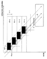
図18は、図16に示した表示例にした場合における網膜上での輝度分布を示している。図18では、原画像の色成分Wを、共通白色成分Wcomと赤色差分ΔR、青色差分ΔB、および緑色差分ΔGとを用いて、
W=Wcom+ΔR+ΔB+ΔG
で表している。また、各色の輝度比は、上述の輝度成分Yの式を考慮して、
Wcom:ΔR:ΔB:ΔG=10:3:1:6
としている。
FIG. 18 shows the luminance distribution on the retina in the case of the display example shown in FIG. In FIG. 18, the color component W of the original image is obtained by using the common white component Wcom and the red difference ΔR, the blue difference ΔB, and the green difference ΔG.
W = Wcom + ΔR + ΔB + ΔG
It is represented by In addition, the luminance ratio of each color takes into account the above-described equation of the luminance component Y,
Wcom: ΔR: ΔB: ΔG = 10: 3: 1: 6
It is said.
この場合、網膜上のP1〜P7の領域での合成輝度は以下のように表される。
P1:Wcom
P2:Wcom+ΔB
P3:Wcom+ΔB+ΔG
P4:W
P5:(ΔR+ΔG)∪(ΔG+ΔB)∪(ΔR+ΔB)
P6:ΔR+ΔG
P7:ΔR
In this case, the combined luminance in the areas P1 to P7 on the retina is expressed as follows.
P1: Wcom
P2: Wcom + ΔB
P3: Wcom + ΔB + ΔG
P4: W
P5: (ΔR + ΔG) ∪ (ΔG + ΔB) ∪ (ΔR + ΔB)
P6: ΔR + ΔG
P7: ΔR
これにより計算される各領域での合成輝度値は例えば、
P1=10、P2=11、P3=17、P4=20、P5=10、P6=9、P7=3
となる。
The composite luminance value in each area calculated by this is, for example,
P1 = 10, P2 = 11, P3 = 17, P4 = 20, P5 = 10, P6 = 9, P7 = 3
It becomes.
ここで、共通白色成分Wcomは、第1の実施の形態において示した図3(A),(B)の例のように抽出されるので、実際には1フレームの画面内では場所に応じて、どれか一色が欠落している。従って、正確には画像の全ての局所的位置で図18の通りになっているわけではない。ここでは、全画像の平均的意味で図18のような状態になることを示している。従って、図18に示した網膜上のP5の領域においては、ΔR>0,ΔG>0,ΔB>0が同時に満たされるということが無い(同時に満たされた成分は白色化可能なレベルとなって共通白色成分Wcomになる)。従って、P5の領域では、画面内画像分布において、いずれか2色を加算したOR集合成分となる。図18の輝度分布を見て分かるように、白色成分を抽出する方法によれば、RGB個々の原色成分が減衰するので、色割れの状況は図15の場合と比較して改善される。ただし、完全に色割れが抑制されるわけではない。 Here, since the common white component Wcom is extracted as in the example of FIGS. 3A and 3B shown in the first embodiment, the common white component Wcom actually depends on the location in the screen of one frame. Any one color is missing. Accordingly, exactly as shown in FIG. 18, not all local positions of the image. Here, the state shown in FIG. 18 is shown in an average sense of all images. Therefore, in the region P5 on the retina shown in FIG. 18, ΔR> 0, ΔG> 0, and ΔB> 0 are not satisfied simultaneously (the components that are satisfied at the same time can be whitened). Common white component Wcom). Therefore, in the area P5, the OR set component is obtained by adding any two colors in the intra-screen image distribution. As can be seen from the luminance distribution of FIG. 18, according to the method of extracting the white component, the primary color components of RGB are attenuated, so that the color breakup situation is improved as compared with the case of FIG. 15. However, color breakup is not completely suppressed.
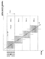
次に、図18の表示例に類似した表示例での輝度分布を図19に示す。図19の表示例では共通白色成分Wcomを用いる点では図18の表示例に類似しているが、RGBの残成分ΔR,ΔG,ΔBの表示順序が異なっている。すなわち、残成分ΔR,ΔG,ΔBに関しては輝度が低い(視感度が低い)ものを時間的に先に表示し、青色差分ΔB、赤色差分ΔR、および緑色差分ΔGの順に表示している。最後に共通白色成分Wcomを表示している。 Next, FIG. 19 shows a luminance distribution in a display example similar to the display example in FIG. The display example of FIG. 19 is similar to the display example of FIG. 18 in that the common white component Wcom is used, but the display order of the remaining RGB components ΔR, ΔG, and ΔB is different. That is, regarding the remaining components ΔR, ΔG, ΔB, those with low luminance (low visibility) are displayed first in time, and are displayed in the order of the blue difference ΔB, the red difference ΔR, and the green difference ΔG. Finally, the common white component Wcom is displayed.
図19の表示例の場合、網膜上のP1〜P7の領域での合成輝度は以下のように表される。
P1:Wcom
P2:Wcom+ΔG
P3:Wcom+ΔG+ΔR
P4:W
P5:(ΔR+ΔG)∪(ΔG+ΔB)∪(ΔR+ΔB)
P6:ΔR+ΔB
P7:ΔB
In the case of the display example of FIG. 19, the combined luminance in the region of P1 to P7 on the retina is expressed as follows.
P1: Wcom
P2: Wcom + ΔG
P3: Wcom + ΔG + ΔR
P4: W
P5: (ΔR + ΔG) ∪ (ΔG + ΔB) ∪ (ΔR + ΔB)
P6: ΔR + ΔB
P7: ΔB
これにより計算される各領域での合成輝度値は例えば、
P1=10、P2=16、P3=19、P4=20、P5=10、P6=4、P7=1
となる。なお、各色の輝度比は、図18の場合と同様にしてある。
The composite luminance value in each area calculated by this is, for example,
P1 = 10, P2 = 16, P3 = 19, P4 = 20, P5 = 10, P6 = 4, P7 = 1
It becomes. Note that the luminance ratio of each color is the same as in the case of FIG.
図19の表示例では、輝度の低い順に表示することで、輝度のエネルギーが共通白色成分Wcom側に偏った状態になることにより、図18で示したものより、色割れが低下する。ただし、完全に色割れが抑制されるわけではない。 In the display example of FIG. 19, by displaying in order of increasing luminance, the luminance energy is biased toward the common white component Wcom, so that the color breakup is lower than that shown in FIG. 18. However, color breakup is not completely suppressed.
(本実施の形態における表示方法)
以上の従来技術による表示手法を踏まえて、本実施の形態における表示方法について説明する。図20において、破線で示した光量グラフは、上述の図19の表示例における1フレーム期間内での光量分布を模式的に示している。図19の表示例では、1フレーム期間の時間軸上で輝度が低い色成分の画像から順に表示し、最後に、輝度の最も明るい共通白色成分Wcomを表示している。このため、共通白色成分Wcom側に輝度のエネルギーが偏り、光量分布(輝度分布が)が時間的に非対称となっている。この光量分布を図20の実線で示したように、中央で輝度エネルギーが高くなり、かつ時間的に対称的な分布にできれば、色割れを抑制できると考えられる。本実施の形態は、そのような表示手法を実現したものである。
(Display method in this embodiment)
Based on the display method according to the conventional technique, the display method in the present embodiment will be described. In FIG. 20, a light amount graph indicated by a broken line schematically shows a light amount distribution within one frame period in the display example of FIG. In the display example of FIG. 19, images of color components having the lowest luminance are displayed in order from the time axis of one frame period, and finally the common white component Wcom having the brightest luminance is displayed. For this reason, the energy of luminance is biased toward the common white component Wcom, and the light amount distribution (luminance distribution) is temporally asymmetric. As shown by the solid line in FIG. 20, if the luminance energy is high at the center and the distribution is symmetrical with respect to time, it is considered that color breakup can be suppressed. The present embodiment realizes such a display method.
図21は、その表示方法の一例を示すものであり、共通白色成分Wcomをフィールド中心にして、明るく視感度の高い色成分が1フレーム期間内でなるべく中央に配置されるようにし、かつ全体的に対称的に色成分を配置するようにした表示例である。この表示例では、原画像から共通白色成分Wcomを抽出し、それを基準画像として1フレーム期間内の中心に配置して表示している。また、共通白色成分Wcomを抽出した後の残成分ΔR,ΔG,ΔBを、信号値が略半分となるように2つに分割した差分成分(1/2)ΔR,(1/2)ΔG,(1/2)Bを作成している。そして、視感度特性を加味した輝度レベルの高い順に基準画像に時間的に前後して表示されるように表示している。すなわち、基準画像(中心画像)である共通白色成分Wcomから時間的に近い順に、時間的に前後して緑色差分(1/2)ΔG、赤色差分(1/2)ΔR、および青色差分(1/2)Bを順次表示している。この表示例では、1フレームが、共通白色成分Wcomと、分割した成分(1/2)ΔR,(1/2)ΔG,(1/2)Bとの合計7フィールドの画像で構成されている。なお、本実施の形態では残成分ΔR,ΔG,ΔBを信号値が完全に半分となるように2つに分割する実施例について記載しているが、信号値が完全に1/2でなくともよい。最終的な網膜上での輝度分布を最適化するために、多少、2つに分割された色成分間の信号レベルが異なっていてもよい。 FIG. 21 shows an example of the display method. The common white component Wcom is centered in the field, and the bright and highly visible color component is arranged as centrally as possible within one frame period. This is a display example in which color components are arranged symmetrically. In this display example, a common white component Wcom is extracted from an original image, and is displayed as a reference image arranged at the center in one frame period. Further, the difference components (1/2) ΔR, (1/2) ΔG, which are obtained by dividing the remaining components ΔR, ΔG, ΔB after the extraction of the common white component Wcom into two so that the signal values are substantially halved. (1/2) B is created. Then, the reference images are displayed so as to be displayed before and after in the descending order of the luminance level in consideration of the visibility characteristics. That is, the green difference (1/2) ΔG, the red difference (1/2) ΔR, and the blue difference (1) are temporally changed in order from the common white component Wcom that is the reference image (center image). / 2) B is displayed sequentially. In this display example, one frame is composed of an image of a total of seven fields including the common white component Wcom and the divided components (1/2) ΔR, (1/2) ΔG, (1/2) B. . In the present embodiment, an example is described in which the remaining components ΔR, ΔG, ΔB are divided into two so that the signal value is completely halved, but the signal value is not necessarily ½. Good. In order to optimize the luminance distribution on the final retina, the signal levels between the color components divided into two may be somewhat different.
図22は、この表示例での網膜上の輝度分布を示している。図22では、原画像の色成分Wが、共通白色成分Wcomと赤色差分ΔR、青色差分ΔB、および緑色差分ΔGとを用いて、
W=Wcom+ΔR+ΔB+ΔG
で表せるものとする。また、各色の輝度比は、上述の輝度成分Yの式を考慮して、
Wcom:ΔR:ΔB:ΔG=10:3:1:6
としている。
FIG. 22 shows the luminance distribution on the retina in this display example. In FIG. 22, the color component W of the original image uses the common white component Wcom and the red difference ΔR, the blue difference ΔB, and the green difference ΔG,
W = Wcom + ΔR + ΔB + ΔG
It can be expressed as In addition, the luminance ratio of each color takes into account the above-described equation of the luminance component Y,
Wcom: ΔR: ΔB: ΔG = 10: 3: 1: 6
It is said.
この場合、網膜上のP1〜P12の領域での合成輝度は以下のように表される。
P1:(1/2)ΔB
P2:(1/2)(ΔR+ΔB)
P3:(1/2)[(ΔR+ΔG)∪(ΔG+ΔB)∪(ΔR+ΔB)]
P4:Wcom+(1/2)(ΔR+ΔG+ΔB)
P5:Wcom+ΔG+(1/2)(ΔR+ΔB)
P6:Wcom+ΔG+ΔR+(1/2)ΔB
P7:Wcom+ΔG+ΔR+(1/2)ΔB
P8:Wcom+ΔG+(1/2)(ΔR+ΔB)
P9:Wcom+(1/2)(ΔR+ΔG+ΔB)
P10:(1/2)[(ΔR+ΔG)∪(ΔG+ΔB)∪(ΔR+ΔB)]
P11:(1/2)(ΔR+ΔB)
P12:(1/2)ΔB
In this case, the combined luminance in the areas P1 to P12 on the retina is expressed as follows.
P1: (1/2) ΔB
P2: (1/2) (ΔR + ΔB)
P3: (1/2) [(ΔR + ΔG) ∪ (ΔG + ΔB) ∪ (ΔR + ΔB)]
P4: Wcom + (1/2) (ΔR + ΔG + ΔB)
P5: Wcom + ΔG + (1/2) (ΔR + ΔB)
P6: Wcom + ΔG + ΔR + (1/2) ΔB
P7: Wcom + ΔG + ΔR + (1/2) ΔB
P8: Wcom + ΔG + (1/2) (ΔR + ΔB)
P9: Wcom + (1/2) (ΔR + ΔG + ΔB)
P10: (1/2) [(ΔR + ΔG) ∪ (ΔG + ΔB) ∪ (ΔR + ΔB)]
P11: (1/2) (ΔR + ΔB)
P12: (1/2) ΔB
これにより計算される各領域での合成輝度値は例えば、
P1=0.5、P2=2、P3=3.3、P4=10、P5=13、P6,P7=14.5、P8=13、P9=10、P10=3.3、P11=2、P12=0.5
となる。
The composite luminance value in each area calculated by this is, for example,
P1 = 0.5, P2 = 2, P3 = 3.3, P4 = 10, P5 = 13, P6, P7 = 14.5, P8 = 13, P9 = 10, P10 = 3.3, P11 = 2, P12 = 0.5
It becomes.
なお、実際には、差分成分(1/2)ΔR,(1/2)ΔG,(1/2)ΔBは、中心画像に比べて信号レベルおよび輝度レベルがかなり低い。図22においては、網膜上の輝度分布の形状を模式的に表す意味合いで、(1/2)ΔBを0.5として記載してあるが、これは説明上の便宜上の値である。また、図18の場合と同様に、共通白色成分Wcomを抽出した結果として、3原色が同時に発生しない部分については、3原色の中から任意の2色を抽出した場合の平均的な輝度として、
(1/2)×[(ΔR+ΔG)∪(ΔG+ΔB)∪(ΔR+ΔB)]
=[(1.5+3)+(3+0.5)+(1.5+0.5)]/3=3.33
としてある。
In practice, the difference components (1/2) ΔR, (1/2) ΔG, and (1/2) ΔB have considerably lower signal levels and luminance levels than the central image. In FIG. 22, (½) ΔB is described as 0.5 in a sense that schematically represents the shape of the luminance distribution on the retina, but this is a value for convenience of explanation. Similarly to the case of FIG. 18, as a result of extracting the common white component Wcom, the average luminance when any two colors are extracted from the three primary colors for the portion where the three primary colors are not generated simultaneously,
(1/2) × [(ΔR + ΔG) ∪ (ΔG + ΔB) ∪ (ΔR + ΔB)]
= [(1.5 + 3) + (3 + 0.5) + (1.5 + 0.5)] / 3 = 3.33
It is as.
図22に示したように、この表示例では、ほぼ中心に輝度ピークがあり、かつ対称的な輝度分布となる状態が得られる。 As shown in FIG. 22, in this display example, a state is obtained in which there is a luminance peak substantially at the center and a symmetrical luminance distribution.
以上のように本実施の形態では、フィールドシーケンシャル方式における動画追従視での色割れの発生を抑制することができる。具体的には、目の追随基準である、明るく視感度の高い画像を中心として時間軸前後に重心配分表示を実施することで、移動表示時に、網膜上のずれ量をバランスさせ、光量重心に対して均等にさせることができる。これにより、不均等な色ずれを目立たなくすることができる。特に、動きベクトルを利用して、視線追随時の色ずれを矯正するものが既存としてあり、または、黒挿入により色割れ改善を図る方法があるが、本実施の形態の表示方法では、動きベクトルを全く使用せず、黒挿入もしないが、モーションエラーが生じない。また、従来では、同一画面内において、異方向に同時に移動するような複数の移動体が存在した時には、色割れ対策が不可能とされていた。これに対し、本実施の形態の表示方法では、観測者がどちらの移動体を追随視している場合でも、他方の移動体の表示に色割れが生じない。また、突然の移動方向の変更が生じた場合でも、網膜上の画像の重なりが保たれるため、色割れが生じない。 As described above, in the present embodiment, it is possible to suppress the occurrence of color breakup in the moving image following view in the field sequential method. Specifically, by performing center-of-gravity distribution display around the time axis centered on a bright and high-visibility image, which is the eye tracking reference, the amount of displacement on the retina is balanced during movement display, and the light intensity center In contrast, it can be made uniform. Thereby, the uneven color shift can be made inconspicuous. In particular, there is an existing method that corrects color misregistration at the time of following the line of sight using a motion vector, or there is a method of improving color breakup by inserting black, but in the display method of the present embodiment, the motion vector Is not used at all, and black is not inserted, but no motion error occurs. Further, conventionally, when there are a plurality of moving bodies that move simultaneously in different directions on the same screen, it has been impossible to take measures against color breakup. On the other hand, in the display method of the present embodiment, no color breaks up in the display of the other moving body, regardless of which moving body the observer is following. Further, even when a sudden change in the direction of movement occurs, the overlapping of images on the retina is maintained, so that color breakup does not occur.
また、上記第1,第2の実施の形態で説明した表示制御手法を組み合わせることにより、目の追随基準である、明るく視感度の高い画像を中心として時間軸前後に重心配分表示を実施する機能を損なわず、重心画像に更に他の色を同時に表示可能にすることで、移動表示時に、網膜上のスリップ量を更に集中的にバランスさせ、光量重心に対して均等にさせ、不均等なズレを目立たなくすることができる。したがって、上記第1および第2の実施の形態と比べ、より色割れを低減することが可能となる。 In addition, by combining the display control methods described in the first and second embodiments, a function of performing center-of-gravity distribution display around the time axis centering on a bright and high-visibility image, which is the eye tracking reference By making it possible to display other colors simultaneously on the center of gravity image without damaging the center of gravity, the amount of slip on the retina can be more intensively balanced during movement display, making it even with respect to the center of gravity of the light amount, and uneven displacement. Can be made inconspicuous. Therefore, color breakup can be further reduced as compared with the first and second embodiments.
更に、本実施の形態の表示方法では、追従視基準となりうる高輝度画像に高解像度成分を配し、かつ、時間的に対称に配置される低輝度の画像群に高解像度成分を配さなくとも、効果的に高解像度感を知覚させ得るという、別の効果もある。 Furthermore, in the display method of the present embodiment, a high-resolution component is arranged in a high-luminance image that can serve as a follow-up visual reference, and a high-resolution component is not arranged in a low-luminance image group that is arranged symmetrically in terms of time. However, there is another effect that a high resolution feeling can be perceived effectively.
以下、第3の実施の形態の変形例をいくつか挙げて説明する。なお、第3の実施の形態における構成要素と同一のものには同一の符号を付し、適宜説明を省略する。 Hereinafter, some modifications of the third embodiment will be described. In addition, the same code | symbol is attached | subjected to the same component as 3rd Embodiment, and description is abbreviate | omitted suitably.
(変形例2)
図23は、第3の実施の形態の変形例(変形例2)に係る画像表示装置5Dの構成例を示している。この画像表示装置5Dは、第3の実施の形態の画像表示装置5Cにおいて、表示制御部1の代わりに表示制御部1Dを備えたものである。表示制御部1Dは、部分駆動化処理部40または部分駆動化処理部40Bを有している。また、信号輝度解析処理部11および輝度最大成分抽出部12の代わりに、信号輝度解析処理部11Dおよび輝度最大成分抽出部12Dを有している。
(Modification 2)
FIG. 23 shows a configuration example of an image display device 5D according to a modification example (modification example 2) of the third embodiment. The image display device 5D includes a display control unit 1D instead of the
信号輝度解析処理部11Dは、他の色成分画像の信号レベルとして、入力画像から共通補色成分Xcom(例えば、共通黄色成分Yecom)を抽出した場合の補色成分の信号レベルを求めるようになっている。 The signal luminance analysis processing unit 11D obtains the signal level of the complementary color component when the common complementary color component Xcom (for example, the common yellow color component Ye com) is extracted from the input image as the signal level of the other color component image. Yes.
輝度最大成分抽出部12Dは、共通白色成分Wcomの代わりに共通補色成分Xcomを用いるようにしたこと以外は、輝度最大成分抽出部12と同様である。
The maximum luminance component extraction unit 12D is the same as the maximum luminance
すなわち、本変形例では、基準画像(中心画像)となるものは共通白色成分Wcomであるとは限らない。補色成分や他の任意の色成分が基準画像として抽出され得る。 That is, in this modification, the reference image (center image) is not necessarily the common white component Wcom. A complementary color component or any other color component can be extracted as a reference image.
図24は、補色の共通黄色成分Yecomが基準画像として抽出された場合の表示例を示している。この表示例では、時間的な中心位置に共通白色成分Wcomに代えて共通黄色成分Yecomが表示されていること以外は、第3の実施の形態で説明した図21の表示例と基本的に同様である。 FIG. 24 shows a display example when the complementary common yellow component Yecom is extracted as the reference image. This display example is basically the same as the display example of FIG. 21 described in the third embodiment, except that the common yellow component Yecom is displayed instead of the common white component Wcom at the temporal center position. It is.
図25は、この表示例での網膜上の輝度分布を示している。図25では、原画像の色成分Wが、共通黄色成分Yecomと赤色差分ΔR、青色差分ΔB、および緑色差分ΔGとを用いて、
W=Yecom+ΔR+ΔB+ΔG
で表せるものとする。また、各色の輝度比は、上述の輝度成分Yの式を考慮して、
Yecom:ΔR:ΔB:ΔG=9:3:1:6
としている。また、合成輝度値の算出に当たり、共通黄色成分Yecomと重なる部分はRとGのレベルが下がりBのレベルが上がることなどを画像の絵柄に応じて、適宜補正している(例えば、(1/2)ΔBの値を倍にする等)。
FIG. 25 shows the luminance distribution on the retina in this display example. In FIG. 25, the color component W of the original image uses the common yellow component Yecom, the red difference ΔR, the blue difference ΔB, and the green difference ΔG,
W = Yecom + ΔR + ΔB + ΔG
It can be expressed as In addition, the luminance ratio of each color takes into account the above-described equation of the luminance component Y,
Yecom: ΔR: ΔB: ΔG = 9: 3: 1: 6
It is said. In calculating the composite luminance value, the portion overlapping the common yellow component Yecom is appropriately corrected according to the picture pattern (for example, (1 / 2) Double the value of ΔB).
この場合、網膜上のP1〜P12の領域での合成輝度は以下のように表される。
P1:(1/2)ΔB
P2:(1/2)(ΔR+ΔB)
P3:(1/2)[(ΔR+ΔG)∪(ΔG+ΔB)∪(ΔR+ΔB)]
P4:Yecom+(1/2)(ΔR+ΔG+ΔB)
P5:Yecom+ΔG+(1/2)(ΔR+ΔB)
P6:Yecom+ΔG+ΔR+(1/2)ΔB
P7:Yecom+ΔG+ΔR+(1/2)ΔB
P8:Yecom+ΔG+(1/2)(ΔR+ΔB)
P9:Yecom+(1/2)(ΔR+ΔG+ΔB)
P10:(1/2)[(ΔR+ΔG)∪(ΔG+ΔB)∪(ΔR+ΔB)]
P11:(1/2)(ΔR+ΔB)
P12:(1/2)ΔB
In this case, the combined luminance in the areas P1 to P12 on the retina is expressed as follows.
P1: (1/2) ΔB
P2: (1/2) (ΔR + ΔB)
P3: (1/2) [(ΔR + ΔG) ∪ (ΔG + ΔB) ∪ (ΔR + ΔB)]
P4: Yecom + (1/2) (ΔR + ΔG + ΔB)
P5: Yecom + ΔG + (1/2) (ΔR + ΔB)
P6: Yecom + ΔG + ΔR + (1/2) ΔB
P7: Yecom + ΔG + ΔR + (1/2) ΔB
P8: Yecom + ΔG + (1/2) (ΔR + ΔB)
P9: Yecom + (1/2) (ΔR + ΔG + ΔB)
P10: (1/2) [(ΔR + ΔG) ∪ (ΔG + ΔB) ∪ (ΔR + ΔB)]
P11: (1/2) (ΔR + ΔB)
P12: (1/2) ΔB
これにより計算される各領域での合成輝度値は例えば、
P1=1、P2=1.25、P3=2.13、P4=14、P5=16.75、P6,P7=16、P8=16.75、P9=14、P10=2.13、P11=1.25、P12=1
となる。なお、ここに示した輝度値は、説明上の便宜上の値である。
The composite luminance value in each area calculated by this is, for example,
P1 = 1, P2 = 1.25, P3 = 2.13, P4 = 14, P5 = 16.75, P6, P7 = 16, P8 = 16.75, P9 = 14, P10 = 2.13, P11 = 1.25, P12 = 1
It becomes. Note that the luminance values shown here are values for convenience of explanation.
このように共通黄色成分Yecomを基準画像として表示した場合、視感度の低い青色成分Bの信号レベルが上昇しても、輝度上昇度が低い。また、赤色成分R、および緑色成分Gがより効果的に共通黄色成分Yecomの表示に貢献する。これにより、時間的な中心画像である共通黄色成分Yecomの輝度が上がる。この表示例では、図22に示した共通白色成分Wcomを表示する場合よりも効果的に、時間方向の輝度重心の広がりが狭くなり、より色割れが少なくなっている。 In this way, when the common yellow component Yecom is displayed as the reference image, the increase in luminance is low even if the signal level of the blue component B having low visibility is increased. Further, the red component R and the green component G contribute to the display of the common yellow component Yecom more effectively. Thereby, the brightness | luminance of the common yellow component Yecom which is a temporal center image increases. In this display example, the spread of the luminance centroid in the time direction is narrowed and color breakup is reduced more effectively than when the common white component Wcom shown in FIG. 22 is displayed.
(変形例3)
なお、図23〜図25の例と同様にして、他の補色(マゼンタ成分Mg、シアン成分Cy)も容易に共通補色成分として分離可能である。図26は、共通マゼンタ成分Mgcomが基準画像として設定された場合の表示例を示している。この表示例では、共通マゼンタ成分Mgcomから時間的に近い順に、時間的に前後して赤色差分(1/2)ΔR、緑色差分(1/2)ΔG、および青色差分(1/2)Bを順次表示している。
(Modification 3)
Note that other complementary colors (magenta component Mg and cyan component Cy) can be easily separated as common complementary components in the same manner as in the examples of FIGS. FIG. 26 shows a display example when the common magenta component Mgcom is set as the reference image. In this display example, the red difference (1/2) ΔR, the green difference (1/2) ΔG, and the blue difference (1/2) B are sequentially changed in time from the common magenta component Mgcom. Displayed sequentially.
(変形例4)
[フィールド中心に配置する色成分を決定する方法]
ここで、一般的な画像においては、常に白色や黄色などの視線追従時の特長が抽出できる明るい画面が常時出ているわけではない。上記第3の実施の形態での表示方法では、以下で説明するようにして中心画像の色成分を決定することにより、そのような場合にも対応できる。
(Modification 4)
[Method for determining the color component to be placed at the center of the field]
Here, in a general image, a bright screen that can always extract features at the time of tracking the line of sight such as white and yellow does not always appear. The display method according to the third embodiment can cope with such a case by determining the color component of the center image as described below.
図27は、変形例4に係るフィールド中心に配置する中心画像の色成分を決定する方法の一例を示している。また、図28および図29は、この処理で算出される輝度値の具体例を示している。なお、この処理は、図11に示した表示制御部1または図23に示した表示制御部1Dによって行われる。特に、信号輝度解析処理部11(もしくは信号輝度解析処理部11D)および輝度最大成分抽出部12(もしくは輝度最大成分抽出部12D)で行われる。
FIG. 27 shows an example of a method for determining the color component of the center image arranged at the center of the field according to the fourth modification. FIG. 28 and FIG. 29 show specific examples of luminance values calculated by this processing. This process is performed by the
表示制御部1,1Dは、フレーム単位で入力画像の色成分を解析し、入力画像を複数の色成分画像に分解した場合の各色成分画像の信号レベルを求める。ここで求めるのは各色成分の画面内での平均値である。具体的には、図28および図29に示したように原画像を、赤色成分、緑色成分、および青色成分の原色画像のみに分解した場合の各原色画像の信号レベルの平均を求める。また、その他の任意の色成分を抽出した場合の他の色成分の信号レベルの平均を求める。例えば、他の色成分の信号レベルとして、共通白色成分Wcomを抽出した場合の信号レベルの平均を求める。また例えば、補色成分(共通黄色成分Yecom等)を抽出した場合の補色成分の信号レベルを求める。
The
表示制御部1,1Dは、これらの信号レベルの平均値に基づいて、フレーム単位で赤色成分、緑色成分、および青色成分の原色画像の平均輝度レベルを算出する(図27のステップS1)。また、共通黄色成分Yecom等の補色成分の平均輝度レベルを算出する(ステップS2)。さらに、共通白色成分Wcomの平均輝度レベルを算出する(ステップ3)。さらに、赤、緑、青の原色画像の平均輝度レベルを合算することで、原画像の全体としての色成分Wの平均輝度レベルを求める(ステップS4)。最後に、ステップS1,S2,S3で得られた各色の平均輝度レベルの値と、ステップS4で得られた画像全体としての平均輝度レベルの値との差分が最小となるものを求める(ステップS5)。
The
このようにして求められた差分が最小となる色成分を、基準画像(中心画像)として設定する。図28の具体例では、平均輝度レベルと平均信号レベルとの双方において共通黄色成分Yecomの差分が最小となっているので、共通黄色成分Yecomを基準画像とする。 The color component that minimizes the difference thus obtained is set as a reference image (center image). In the specific example of FIG. 28, since the difference in the common yellow component Yecom is the smallest in both the average luminance level and the average signal level, the common yellow component Yecom is used as the reference image.
なお、このような処理で基準画像を決定することで、共通白色成分Wcomや共通黄色成分Yecom以外の色成分が基準画像として設定されることがある。具体的には、前述した図26は、共通マゼンタ成分Mgcomが基準画像として設定された場合の表示例を示している。例えば、輝度分布として青色成分よりも多いものの、緑色成分が通常よりも少な目であるような場合、このような表示例となる。 Note that by determining the reference image by such processing, color components other than the common white component Wcom and the common yellow component Yecom may be set as the reference image. Specifically, FIG. 26 described above shows a display example when the common magenta component Mgcom is set as the reference image. For example, when the luminance distribution is larger than the blue component, but the green component has fewer eyes than usual, such a display example is obtained.
(変形例5)
[フィールド削減方法]
図30は、上記第3の実施の形態の表示方法を採用しつつ、1フレーム期間内でのフィールド数を削減する方法を示している。第3の本実施の形態の表示方法を採用して、例えば図24のような表示状態になった場合(変形例2)、フレーム内の最外部に表示される青色成分は輝度が非常に低くなる。このことを利用して、例えば前後ABそれぞれのフレームの中の青色の情報を半分ずつ共用化させ単純に合算合成した画像を作成する。すなわち、隣接する青色のフィールド画像の信号値が(1/2)ΔBaと(1/2)ΔBbとであった場合、合成した値は、
(1/2)ΔBa+(1/2)ΔBb
となる。この合成した画像を隣接するフレーム間でまとめて表示する。これにより、図24の表示状態では1フレーム当たりのフィールド構成枚数が7フィールドであったものを、図30の表示状態では6フィールドとすることができる。このような表示は、表示制御部1,1Dにおいて、時間的に隣接する第1のフレームと第2のフレームとの間で、時間的に隣接する2つのフィールド画像を合成し、1フィールド期間にまとめて表示させる制御を行うことで実現できる。
(Modification 5)
[Field reduction method]
FIG. 30 shows a method of reducing the number of fields in one frame period while adopting the display method of the third embodiment. When the display method of the third embodiment is adopted and the display state is as shown in FIG. 24 (Modification 2), the blue component displayed at the outermost part in the frame has a very low luminance. Become. By utilizing this, for example, the blue information in each of the frames of the front and rear AB is shared in half and an image that is simply added and synthesized is created. That is, when the signal values of the adjacent blue field images are (1/2) ΔBa and (1/2) ΔBb, the combined value is
(1/2) ΔBa + (1/2) ΔBb
It becomes. The synthesized images are displayed together between adjacent frames. Thus, in the display state of FIG. 24, the number of field constituents per frame is 7 fields, but in the display state of FIG. 30, 6 fields can be obtained. In such a display, the
(変形例6)
[視感度補正をした表示方法]
これまでは、上記第3の実施の形態の表示方法の説明を、色覚特性と視聴環境とが標準的なモデルを想定して行ったが、個人的な色覚特性の差や視聴環境の差を考慮した視感度補正を行うようにしてもよい。この視感度補正は、信号輝度解析処理部11,11Dおよび輝度最大成分抽出部12,12Dで使用する輝度変換式を適宜変更することで実現できる。
(Modification 6)
[Display method with corrected visibility]
Up to this point, the display method of the third embodiment has been described on the assumption that the color vision characteristics and the viewing environment are standard models. You may make it perform the visibility correction | amendment which considered. This visibility correction can be realized by appropriately changing the luminance conversion formula used in the signal luminance
図31は、明るい場所(明所視)での人間の視感度特性を示している。図32は、暗い場所(暗所視)での人間の視感度特性を示している。明所視では図31に示したように人間の視感度特性は、555nmで最大ピークとなる比視感度を有している。この場合、R:G:Bの各原色での感度比率はおおよそ、R:G:B=3:6:1である。この感度比率を加味して標準的なTV規格では輝度成分Yを、おおよそ、
Y=0.3R+0.6G+0.1B
で表すようにしている。
FIG. 31 shows human visibility characteristics in a bright place (photopic vision). FIG. 32 shows human visibility characteristics in a dark place (dark vision). In photopic vision, as shown in FIG. 31, the human visual sensitivity characteristic has a specific visual sensitivity that has a maximum peak at 555 nm. In this case, the sensitivity ratio for each primary color of R: G: B is approximately R: G: B = 3: 6: 1. In consideration of this sensitivity ratio, in the standard TV standard, the luminance component Y is approximately
Y = 0.3R + 0.6G + 0.1B
Is expressed as.
一方、暗所視ではプルキンエシフトが起こり、図32に示したように最大ピークとなる部分が500nm付近にシフトするような比視感度特性となる。この場合、R:G:Bの各原色での感度比率はおおよそ、R:G:B=0.1:2:5である。従って、信号輝度解析処理部11および輝度最大成分抽出部12で使用する輝度変換式を、おおよそ、
Y=0.1R+2G+5B
となるようなものに変更することで、暗所視に最適な基準画像を抽出して暗所視に最適な表示を実現できる。なお、実使用上は、この波長の感度シフトは、色がわからなくなるほどの暗闇という非常に暗い特殊な環境の輝度で起こる。このため、周囲環境が大変暗くて、しかも、表示画面も大変暗いという極端に暗い場合に限ってこのような視感度補正を行うとよい。
On the other hand, Purkinje shift occurs in the dark place vision, and the specific visibility characteristic is such that the maximum peak portion shifts to around 500 nm as shown in FIG. In this case, the sensitivity ratio for each primary color of R: G: B is approximately R: G: B = 0.1: 2: 5. Therefore, the luminance conversion formula used in the signal luminance
Y = 0.1R + 2G + 5B
By changing to such a thing, it is possible to extract a reference image that is optimal for scotopic vision and realize a display that is optimal for scotopic vision. In actual use, this wavelength sensitivity shift is caused by the brightness of a very dark special environment, dark enough to make the color unclear. For this reason, it is preferable to perform such visibility correction only when the surrounding environment is very dark and the display screen is extremely dark, which is extremely dark.
図33は、色覚異常がある場合(第1色盲、第2色盲)の視感度特性を正常者と比較して示している。図34は、色覚異常がある場合の波長識別特性を正常者と比較して示している。図33から分かるように、第1色盲の人では正常者に比べて赤色領域を暗く感じている。また、図34から分かるように、第1色盲および第2色盲の人では正常者に比べて長波長側の波長識別ができていない。このような代表的な色覚異常の視感度特性に応じた輝度変換式を用いることで、個人的な視覚特性差に応じた最適な基準画像を抽出して個人に最適な表示を実現できる。 FIG. 33 shows the visual sensitivity characteristics when there is a color blindness (first color blindness, second color blindness) compared with a normal person. FIG. 34 shows the wavelength discrimination characteristics when there is a color blindness in comparison with a normal person. As can be seen from FIG. 33, the first color blind person feels the red region darker than the normal person. Further, as can be seen from FIG. 34, the first color blind and the second color blind person cannot identify the wavelength on the longer wavelength side compared to the normal person. By using such a luminance conversion formula corresponding to the visual sensitivity characteristic of a typical color vision abnormality, an optimal reference image corresponding to a personal visual characteristic difference can be extracted to realize an optimal display for an individual.
(その他の変形例)
以上、実施の形態および変形例をいくつか挙げて本発明を説明したが、本発明はこれらの実施の形態等に限定されず、種々の変形が可能である。
(Other variations)
The present invention has been described above with some embodiments and modifications. However, the present invention is not limited to these embodiments and the like, and various modifications are possible.
例えば、上記第3の実施の形態では、例えば、フィールドレートは固定として例えば360Hzのフィールドレートとし、1フレーム期間内で各フィールド期間は同一であるものとしてもよいし、1フレーム期間内でフィールドレートを可変にしてもよい。例えば、時間軸上で中心画像とその両側のフィールド画像のみを1/360秒のフィールド期間で表示し、さらにその外側に配置されるフィールド画像を1/240秒で表示するようにすることも可能である。すなわち、時間軸上で中心画像を中心にしてその他のフィールド画像が時間的に対称的に配置されるようにさえなっていれば、1フレーム期間内でフィールドレートを可変にしてもよい。この場合にも、最終的に網膜上での輝度分布は対称的になるので、色割れの抑制効果はある。 For example, in the third embodiment, for example, the field rate is fixed and, for example, the field rate is 360 Hz, and each field period may be the same within one frame period, or the field rate may be within one frame period. May be variable. For example, it is possible to display only the central image and the field images on both sides on the time axis in a field period of 1/360 seconds, and further display field images arranged outside the center image in 1/240 seconds. It is. That is, as long as the other field images are arranged symmetrically with respect to the center image on the time axis, the field rate may be variable within one frame period. Also in this case, since the luminance distribution on the retina finally becomes symmetric, there is an effect of suppressing color breakup.
更に、上記第3の実施の形態では、最終的に輝度レベルに基づいて特定された色成分画像を常に中心画像に設定する場合について説明したが、中心画像に設定する色成分を輝度分布に大きな影響を与えない範囲で変えるようにしてもよい。例えば輝度レベルで判断した場合には黄色が中心画像としてベストな選択であるが、信号レベルで判断した場合には白色が中心画像としてベストな選択であることが考えられる。また、その場合、輝度レベルのみで判断しても、例えば黄色と白色とでそれほど輝度レベルに大きな差がないことが考えられる。そのような場合、中心画像に設定する画像として、例えば輝度レベルが1番目に高い色成分(例えば黄色)と2番目に高い色成分(例えば白色)とを任意のフレームで変えるようにしてもよい。例えば「BRGWGRB」の構成のフレーム画像と「BRGYeGRB」の構成のフレーム画像とを時間軸上で任意に混在させて表示するようにしてもよい。 Furthermore, in the third embodiment, the case where the color component image finally specified based on the luminance level is always set as the central image has been described. However, the color component set in the central image has a large luminance distribution. You may make it change in the range which does not affect. For example, yellow is the best selection as the central image when judged by the luminance level, but white is the best choice as the central image when judged by the signal level. In that case, it is conceivable that even if the determination is made only with the luminance level, for example, there is not much difference in luminance level between yellow and white. In such a case, as an image to be set as the central image, for example, a color component having the first highest luminance level (for example, yellow) and a color component having the second highest level (for example, white) may be changed in an arbitrary frame. . For example, a frame image having a configuration of “BRGWGRB” and a frame image having a configuration of “BRGYeGRB” may be arbitrarily mixed and displayed on the time axis.
1,1D,4,4A,4B…表示制御部、2…表示パネル(表示部)、3…バックライト、5,5A,5B,5C,5D…画像表示装置、11,11D…信号輝度解析処理部、12,12D…輝度最大成分抽出部、13…出力順序決定部、14…比視感度曲線補正部、15…選択部、16…信号演算処理部、17…信号レベル処理部、18…出力信号選択スイッチャ、19…バックライト色光選択スイッチャ、20,24,30…追従視基準軸、21…単位フレーム、22…時間軸、23…空間軸、25…観測者、26…部分照射領域、3R…赤色LED、3G…緑色LED、3B…青色LED、36…部分発光領域、40,40B…部分駆動化処理部、41,41B…低解像度化処理部、42R,42G,42B…拡散部、43R,43G,43B…除算部、44,44A…共通最小値抽出部、45R,45G,45B…減算部、46,46A,46B…出力信号選択スイッチャ、47,47A…バックライト色光選択スイッチャ、71…発光面イメージ、72…パネル面イメージ、73,73ΔR,73ΔG,73ΔB,73B,73Wcom,73Yecom…合成イメージ(フィールド映像)。
DESCRIPTION OF
Claims (14)
前記光源部から射出された色光を入力映像信号に基づいて変調する表示パネルと、
前記入力映像信号により構成される入力フレーム画像を複数のフィールド画像に分解すると共に、これらの複数のフィールド画像がフィールドシーケンシャル方式により時分割表示されるように、前記光源部の各部分発光部および前記表示パネルを制御する表示制御部と
を備え、
前記表示制御部は、
前記入力映像信号に対して所定の低解像度化処理を行い、その処理結果に基づき、前記複数の部分発光部の選択的発光動作によって形成されるべき発光パターンを生成すると共に、前記入力映像信号の各画素信号レベルを前記発光パターンのうちの対応する部分発光部の発光レベルによってそれぞれ除算することにより、部分駆動用映像信号を生成する部分駆動処理部と、
前記部分駆動用映像信号により構成される部分駆動用フレーム画像における色成分を解析することにより、この部分駆動用フレーム画像から、赤色成分、緑色成分および青色成分の3つの原色成分のうちの2つ以上の原色成分に共通した大きさの第1の共通輝度部分を抽出する信号解析部と、
前記部分駆動用フレーム画像から前記第1の共通輝度部分を差し引くことにより個々の原色成分ごとに第1の差分画像を求めると共に、個々の原色成分ごとに得られた第1の差分画像と、前記第1の共通輝度部分により構成される第1の共通画像とを、前記複数のフィールド画像としてそれぞれ前記表示パネルに時分割的に順次出力する信号出力部と、
個々の原色成分ごとの第1の差分画像が選択出力される個々の第1のフィールド期間では、その原色成分に対応する原色光のみが射出されると共に、前記第1の共通画像が出力される第2のフィールド期間では、前記第1の共通輝度部分を構成する前記2つ以上の原色成分にそれぞれ対応する複数の原色光がすべて射出されるように、前記発光パターンと前記第1の共通画像とに基づいて、前記光源部から射出される色光を選択する色光選択部と
を有する画像表示装置。 Controlled independently of each other, a light source section each having a plurality of emission subsections which emits a plurality of color lights separately,
A display panel for modulating based on an input video signal a color light Desa morphism the light source unit or al,
The input frame image composed of the input video signal is decomposed into a plurality of field images, and each of the partial light emitting units of the light source unit and the plurality of field images are displayed in a time-sequential manner by a field sequential method. A display control unit for controlling the display panel,
The display control unit
There line a predetermined resolution reduction processing to the input video signal, together with the basis of the processing result, and generates a light emission pattern to be formed by selective emission operation of the plurality of emission subsections, the input video signal A partial drive processing unit that generates a partial drive video signal by dividing each pixel signal level by a light emission level of a corresponding partial light emitting unit in the light emission pattern,
By analyzing the color components in configured partitioning-drive frame image by the partitioning-drive image signals, from the partitioning-drive frame image, two of the three primary color components of the red component, green component and blue component A signal analysis unit for extracting a first common luminance portion having a size common to the above primary color components;
With obtaining the first differential image for each individual primary color components by pulling Kukoto insert the first common luminance portion from the partial drive frame image, a first differential image obtained for each individual primary color components and a first co Tsuga picture constituted by the first common luminance portion, and a signal output unit for outputting time division and sequentially to each of the display panel as a plurality of field images,
Individual first field period a first difference image for each individual primary color components is selected and output, with only the primary color light is emitted corresponding to the primary color components, said first co Tsuga image out in the second field period that is force, so that a plurality of primary color light corresponding to the prior SL two or more primary color components constituting the first common luminance portion is injected all, the said emission pattern first on the basis of the first co-Tsuga image, an image display device having a color light selection section for selecting a color light emitted from the light source unit.
前記色光選択部は、前記第2のフィールド期間において、前記2つの原色成分に対応する2つの原色光がともに射出されるように、前記光源部から射出される色光を選択する
請求項1に記載の画像表示装置。 The first common luminance portion has a luminance of a size common to two primary color components of the three primary color components,
The color light selection unit selects the color light emitted from the light source unit so that two primary color lights corresponding to the two primary color components are emitted together in the second field period. Image display device.
前記色光選択部は、前記第2のフィールド期間において、赤色光および緑色光がともに射出されるように、前記光源部から射出される色光を選択する
請求項2に記載の画像表示装置。 The first common luminance portion corresponds to a yellow component having a luminance of a size common to the red component and the green component,
The image display device according to claim 2, wherein the color light selection unit selects the color light emitted from the light source unit so that both red light and green light are emitted in the second field period.
前記色光選択部は、前記他のフィールド期間において前記光源部における全ての部分発光部を選択し、一括して発光させるように制御する
請求項2または請求項3に記載の画像表示装置。 The signal output unit outputs a field image corresponding to a primary color component other than the two primary color components of the three primary color components in another field period;
The color light selection unit selects all of the emission subsections in the light source unit in the other field period, the image display apparatus according to claim 2 or claim 3 is controlled so as to emit light at once.
前記色光選択部は、前記第2のフィールド期間において、赤色光、緑色光および青色光の3つの原色光のすべてが射出されるように、前記光源部から射出される色光を選択する
請求項1に記載の画像表示装置。 The first common luminance portion corresponds to a white component having a luminance of a size common to all of the three primary color components,
The color light selection unit selects color light emitted from the light source unit so that all three primary color lights of red light, green light, and blue light are emitted in the second field period. The image display device described in 1.
前記表示制御部は、前記信号解析部で求められた前記各色成分画像の信号レベルに基づいて、個々の色成分画像ごとに、視感度特性を加味した輝度レベルを算出すると共に、より高い輝度レベルの色成分画像を基準画像として決定する基準画像決定部をさらに備え、
前記信号出力部は、さらに、前記部分駆動用フレーム画像から前記基準画像を差し引くことにより個々の色成分ごとに第2の差分画像を求めると共に、得られた個々の色成分ごとの第2の差分画像を2つに分割し、得られた各分割画像と前記基準画像とを、前記複数のフィールド画像としてそれぞれ前記表示パネルに時分割的に順次出力するという処理を行い、
前記表示制御部は、1フレーム期間内で時間的な中心位置に前記基準画像が表示されると共に、前記分割画像が、視感度特性を加味した輝度レベルの高いものほど前記基準画像の前後におけるより近い位置に表示されるように、前記信号出力部から出力する複数のフィールド画像の1フレーム内での出力順序を制御する出力順序決定部をさらに備えた
請求項1ないし請求項5のいずれか1項に記載の画像表示装置。 Before SL signal analysis unit further by analyzing the color component of the input frame image, it obtains a signal level of each color component image in the case of decomposing the input frame image into a plurality of color component images,
Wherein the display control unit based on the signal level of each color component image obtained by the signal analyzing unit, for each individual color component image, and calculates the brightness level in consideration of the visibility characteristic, higher brightness levels A reference image determination unit that determines the color component image of
Said signal output section further wherein with obtaining a second difference image for each individual color components by pulling Kukoto insert the partitioning-drive frame image or al before Symbol reference picture image, each individual color components obtained the second difference image is divided into two, the each divided image obtained with the reference image, performs a process of time division manner sequentially outputs to each of the display panel as a plurality of field images of,
Wherein the display control unit, together with the reference image to the temporal central position in one frame period is displayed, the divided image is from before and after the brightness level of high Monohodo the reference image in consideration of the visibility characteristic The output order determination part which controls the output order in one frame of the some field image output from the said signal output part so that it may be displayed in the near position was further provided. The image display device according to item.
請求項6に記載の画像表示装置。 When the reference image determination unit displays a color component image for one frame on the display panel, the combined luminance distribution on the viewer's retina has a high luminance in the central portion and a low luminance in the peripheral portion, and The image display device according to claim 6, wherein a color component image that satisfies a condition that a spread width of the combined luminance distribution is minimized is determined as the reference image.
請求項6または請求項7に記載の画像表示装置。 The signal analysis unit, extracting the signal levels of the three primary color component images obtained when decomposing the input frame image only to the three primary colors Ingredient, any other color component from the input frame image The image display device according to claim 6, wherein a signal level of another color component image obtained in the case is obtained .
請求項8に記載の画像表示装置。 When the signal analysis unit extracts a signal level of a white component image obtained when a white component is extracted from the input frame image as a signal level of the other color component image, and a complementary color component from the input frame image The image display device according to claim 8, wherein at least a signal level of a complementary color component image obtained in the step is obtained .
請求項6ないし請求項9のいずれか1項に記載の画像表示装置。 The reference image determination unit may have use a plurality of luminance transformation equation predetermined luminance conversion formula is selected from among the image display according to any one of claims 6 to 9 for calculating the brightness level apparatus.
請求項10に記載の画像表示装置。 The image display device according to claim 10, wherein the reference image determination unit selectively uses at least two types of luminance conversion formulas corresponding to photopic vision and scotopic vision as the luminance conversion formula.
請求項10に記載の画像表示装置。 The said reference | standard image determination part uses selectively two types of brightness | luminance conversion formulas, at least the brightness | luminance conversion formula for normal viewers, and the brightness | luminance conversion formula for color blind persons, as said brightness | luminance conversion formula. Image display device.
請求項6ないし請求項12のいずれか1項に記載の画像表示装置。 The display control unit combines two temporally adjacent field images into one field image between the temporally adjacent first frame and the second frame, and combines the combined field images. The image display device according to any one of claims 6 to 12, wherein control is performed to collectively display in one field period.
前記基準画像決定部が、前記第2の共通輝度部分により構成される第2の共通画像を、前記基準画像として決定する
請求項6ないし請求項13のいずれか1項に記載の画像表示装置。 The signal analysis unit further extracts, from the input frame image, a second common luminance portion having a size common to two or more primary color components of the three primary color components,
The image display device according to any one of claims 6 to 13, wherein the reference image determination unit determines a second common image configured by the second common luminance portion as the reference image .
Priority Applications (3)
| Application Number | Priority Date | Filing Date | Title |
|---|---|---|---|
| JP2009099177A JP5152084B2 (en) | 2009-04-15 | 2009-04-15 | Image display device |
| US12/756,831 US20100265281A1 (en) | 2009-04-15 | 2010-04-08 | Image display device |
| CN201010149893.8A CN101866624B (en) | 2009-04-15 | 2010-04-08 | Image display device |
Applications Claiming Priority (1)
| Application Number | Priority Date | Filing Date | Title |
|---|---|---|---|
| JP2009099177A JP5152084B2 (en) | 2009-04-15 | 2009-04-15 | Image display device |
Publications (3)
| Publication Number | Publication Date |
|---|---|
| JP2010250061A JP2010250061A (en) | 2010-11-04 |
| JP2010250061A5 JP2010250061A5 (en) | 2012-05-10 |
| JP5152084B2 true JP5152084B2 (en) | 2013-02-27 |
Family
ID=42958322
Family Applications (1)
| Application Number | Title | Priority Date | Filing Date |
|---|---|---|---|
| JP2009099177A Expired - Fee Related JP5152084B2 (en) | 2009-04-15 | 2009-04-15 | Image display device |
Country Status (3)
| Country | Link |
|---|---|
| US (1) | US20100265281A1 (en) |
| JP (1) | JP5152084B2 (en) |
| CN (1) | CN101866624B (en) |
Cited By (2)
| Publication number | Priority date | Publication date | Assignee | Title |
|---|---|---|---|---|
| US9966014B2 (en) | 2013-11-13 | 2018-05-08 | Sharp Kabushiki Kaisha | Field sequential liquid crystal display device and method of driving same |
| US10002573B2 (en) | 2013-12-13 | 2018-06-19 | Sharp Kabushiki Kaisha | Field sequential display device and drive method therefor |
Families Citing this family (31)
| Publication number | Priority date | Publication date | Assignee | Title |
|---|---|---|---|---|
| JP4780422B2 (en) * | 2008-12-22 | 2011-09-28 | ソニー株式会社 | Image display apparatus and method |
| WO2011132437A1 (en) * | 2010-04-20 | 2011-10-27 | シャープ株式会社 | Display device |
| US8988337B2 (en) * | 2010-07-02 | 2015-03-24 | Semiconductor Energy Laboratory Co., Ltd. | Driving method of liquid crystal display device |
| JP5536888B2 (en) * | 2010-07-09 | 2014-07-02 | シャープ株式会社 | Liquid crystal display |
| JP2012048220A (en) | 2010-07-26 | 2012-03-08 | Semiconductor Energy Lab Co Ltd | Liquid crystal display device and its driving method |
| EP2652728A2 (en) | 2010-12-17 | 2013-10-23 | Dolby Laboratories Licensing Corporation | Quantum dots for display panels |
| US9165494B2 (en) | 2010-12-28 | 2015-10-20 | Sharp Kabushiki Kaisha | Signal conversion circuit and multi-primary color liquid crystal display device comprising same |
| WO2012157554A1 (en) * | 2011-05-18 | 2012-11-22 | シャープ株式会社 | Image display device and image display method |
| WO2012157553A1 (en) * | 2011-05-18 | 2012-11-22 | シャープ株式会社 | Image display device and image display method |
| JP2013044831A (en) * | 2011-08-23 | 2013-03-04 | Seiko Epson Corp | Projector |
| JP2013186369A (en) * | 2012-03-09 | 2013-09-19 | Seiko Epson Corp | Image display device and image display method |
| US9208731B2 (en) | 2012-10-30 | 2015-12-08 | Pixtronix, Inc. | Display apparatus employing frame specific composite contributing colors |
| US9265458B2 (en) | 2012-12-04 | 2016-02-23 | Sync-Think, Inc. | Application of smooth pursuit cognitive testing paradigms to clinical drug development |
| JP6105928B2 (en) * | 2012-12-27 | 2017-03-29 | 株式会社ジャパンディスプレイ | Liquid crystal display |
| US9380976B2 (en) | 2013-03-11 | 2016-07-05 | Sync-Think, Inc. | Optical neuroinformatics |
| CN103234476B (en) * | 2013-04-01 | 2014-04-02 | 廖怀宝 | Method for identifying object two-dimensional outlines |
| US9728148B2 (en) * | 2013-08-08 | 2017-08-08 | Sharp Kabushiki Kaisha | Liquid crystal display apparatus and method of driving the liquid crystal display apparatus |
| US10326969B2 (en) * | 2013-08-12 | 2019-06-18 | Magna Electronics Inc. | Vehicle vision system with reduction of temporal noise in images |
| US9230345B2 (en) * | 2013-10-02 | 2016-01-05 | Pixtronix, Inc. | Display apparatus configured for display of lower resolution composite color subfields |
| KR102106271B1 (en) * | 2013-10-24 | 2020-05-06 | 삼성디스플레이 주식회사 | Display apparatus and driving method thereof |
| KR20150081174A (en) * | 2014-01-03 | 2015-07-13 | 삼성디스플레이 주식회사 | Liquid crystal display apparatus and the drivinig method of the same |
| US20170221407A1 (en) * | 2014-02-26 | 2017-08-03 | Sharp Kabushiki Kaisha | Field-sequential image display device and image display method |
| KR102199218B1 (en) * | 2014-09-05 | 2021-01-07 | 삼성디스플레이 주식회사 | Display apparatus, Display control apparatus and Display method |
| CN104240213B (en) * | 2014-09-05 | 2017-12-15 | 京东方科技集团股份有限公司 | A kind of display methods and display device |
| US10424234B2 (en) * | 2014-10-07 | 2019-09-24 | Christie Digital Systems Usa, Inc. | De-saturated colour injected sequences in a colour sequential image system |
| US10192477B2 (en) * | 2015-01-08 | 2019-01-29 | Lighthouse Technologies Limited | Pixel combination of full color LED and white LED for use in LED video displays and signages |
| KR20160116266A (en) * | 2015-03-27 | 2016-10-07 | 삼성디스플레이 주식회사 | Display apparatus and method of driving the same |
| US10573250B2 (en) * | 2015-06-19 | 2020-02-25 | Sharp Kabushiki Kaisha | Liquid crystal display device and driving method therefor |
| JP2017213040A (en) * | 2016-05-30 | 2017-12-07 | セイコーエプソン株式会社 | Biological information acquisition device and biological information acquisition method |
| CN109545155B (en) * | 2019-02-25 | 2019-05-07 | 南京熊猫电子制造有限公司 | A kind of device and method for improving field sequence and showing color uniformity |
| CN110225189B (en) * | 2019-05-20 | 2021-05-04 | 北京小米移动软件有限公司 | Display control method and device |
Family Cites Families (17)
| Publication number | Priority date | Publication date | Assignee | Title |
|---|---|---|---|---|
| DE69839542D1 (en) * | 1997-08-07 | 2008-07-10 | Hitachi Ltd | Color image display device and method |
| WO2001022391A1 (en) * | 1999-09-17 | 2001-03-29 | Matsushita Electric Industrial Co., Ltd. | Image display device |
| JP2001202057A (en) * | 2000-01-21 | 2001-07-27 | Mitsubishi Electric Corp | Image display device and image display method |
| JP3660610B2 (en) * | 2001-07-10 | 2005-06-15 | 株式会社東芝 | Image display method |
| US7064740B2 (en) * | 2001-11-09 | 2006-06-20 | Sharp Laboratories Of America, Inc. | Backlit display with improved dynamic range |
| JP4493274B2 (en) * | 2003-01-29 | 2010-06-30 | 富士通株式会社 | Display device and display method |
| CN101002480A (en) * | 2004-08-13 | 2007-07-18 | 皇家飞利浦电子股份有限公司 | System and method for reducing complexity in a color sequential display system |
| JP5116208B2 (en) * | 2004-11-19 | 2013-01-09 | 株式会社ジャパンディスプレイイースト | Image signal display device |
| JP4701863B2 (en) * | 2005-06-24 | 2011-06-15 | 株式会社日立製作所 | Signal conversion method and signal conversion apparatus |
| JP2007256496A (en) * | 2006-03-22 | 2007-10-04 | Fujifilm Corp | Liquid crystal display |
| JP2007264211A (en) * | 2006-03-28 | 2007-10-11 | 21 Aomori Sangyo Sogo Shien Center | Color display method for color-sequential display liquid crystal display apparatus |
| JP3996178B1 (en) * | 2006-07-14 | 2007-10-24 | シャープ株式会社 | Liquid crystal display |
| JP2008165048A (en) * | 2006-12-28 | 2008-07-17 | Toshiba Corp | Color display device and color display method |
| JP2008268323A (en) * | 2007-04-17 | 2008-11-06 | Seiko Epson Corp | Display device, driving method of display device, and electronic equipment |
| TWI348149B (en) * | 2007-11-12 | 2011-09-01 | Au Optronics Corp | Method for driving field sequential lcd backlight |
| JP4979776B2 (en) * | 2008-01-31 | 2012-07-18 | シャープ株式会社 | Image display device and image display method |
| JP4780422B2 (en) * | 2008-12-22 | 2011-09-28 | ソニー株式会社 | Image display apparatus and method |
-
2009
- 2009-04-15 JP JP2009099177A patent/JP5152084B2/en not_active Expired - Fee Related
-
2010
- 2010-04-08 US US12/756,831 patent/US20100265281A1/en not_active Abandoned
- 2010-04-08 CN CN201010149893.8A patent/CN101866624B/en not_active Expired - Fee Related
Cited By (2)
| Publication number | Priority date | Publication date | Assignee | Title |
|---|---|---|---|---|
| US9966014B2 (en) | 2013-11-13 | 2018-05-08 | Sharp Kabushiki Kaisha | Field sequential liquid crystal display device and method of driving same |
| US10002573B2 (en) | 2013-12-13 | 2018-06-19 | Sharp Kabushiki Kaisha | Field sequential display device and drive method therefor |
Also Published As
| Publication number | Publication date |
|---|---|
| US20100265281A1 (en) | 2010-10-21 |
| CN101866624B (en) | 2013-01-09 |
| JP2010250061A (en) | 2010-11-04 |
| CN101866624A (en) | 2010-10-20 |
Similar Documents
| Publication | Publication Date | Title |
|---|---|---|
| JP5152084B2 (en) | Image display device | |
| JP4780422B2 (en) | Image display apparatus and method | |
| JP2010250061A5 (en) | ||
| US20120062584A1 (en) | Image display apparatus and method | |
| JP5401827B2 (en) | Display device, display device driving method, and electronic apparatus | |
| JP3878030B2 (en) | Image display device and image display method | |
| JP3766274B2 (en) | Time-division color display device and display method | |
| JP4399087B2 (en) | LIGHTING SYSTEM, VIDEO DISPLAY DEVICE, AND LIGHTING CONTROL METHOD | |
| US8184087B2 (en) | Display method for LCD device with reduced color break-up | |
| JP4170899B2 (en) | Apparatus, system and method for color display | |
| KR100420426B1 (en) | Method for displaying luminous gradation | |
| TWI413078B (en) | Color sequential controlling method and field sequential color display using the same | |
| US7397484B2 (en) | Method for displaying an image | |
| JP2008165048A (en) | Color display device and color display method | |
| JP5827682B2 (en) | Image display device and image display method | |
| JP2007334223A (en) | Liquid crystal display device | |
| WO2012157553A1 (en) | Image display device and image display method | |
| Langendijk et al. | Suppression of color breakup in color‐sequential multi‐primary projection displays | |
| JP6122289B2 (en) | Projector, projector control method and program | |
| TWI410938B (en) | Display method for color sequential display | |
| KR20240031319A (en) | light therapy device | |
| JP2008026816A (en) | Color display device and method | |
| Zhang et al. | 65.2: A 120Hz Spatio‐Temporal Color Display Without Color Breakup | |
| US20180082646A1 (en) | Field sequential color type display device and control method therefor | |
| Thollot et al. | Evaluation of next-generation color wheels for field sequential color displays |
Legal Events
| Date | Code | Title | Description |
|---|---|---|---|
| A521 | Request for written amendment filed |
Free format text: JAPANESE INTERMEDIATE CODE: A523 Effective date: 20120316 |
|
| A621 | Written request for application examination |
Free format text: JAPANESE INTERMEDIATE CODE: A621 Effective date: 20120316 |
|
| A977 | Report on retrieval |
Free format text: JAPANESE INTERMEDIATE CODE: A971007 Effective date: 20121017 |
|
| TRDD | Decision of grant or rejection written | ||
| A01 | Written decision to grant a patent or to grant a registration (utility model) |
Free format text: JAPANESE INTERMEDIATE CODE: A01 Effective date: 20121106 |
|
| A61 | First payment of annual fees (during grant procedure) |
Free format text: JAPANESE INTERMEDIATE CODE: A61 Effective date: 20121119 |
|
| FPAY | Renewal fee payment (event date is renewal date of database) |
Free format text: PAYMENT UNTIL: 20151214 Year of fee payment: 3 |
|
| FPAY | Renewal fee payment (event date is renewal date of database) |
Free format text: PAYMENT UNTIL: 20151214 Year of fee payment: 3 |
|
| LAPS | Cancellation because of no payment of annual fees |